friction spot joining of lightweight metals and fiber ... · pdf file1 friction spot joining...
TRANSCRIPT

Friction Spot Joining of Lightweight Metals and Fiber-Reinforced Polymer Hybrid Structures Dr.-Ing. Sergio Amancio Helmholtz Zentrum Geesthacht - Zentrum für Material- und Küstenforschung
Short Description of the Project
The increasing level of CO2-emissions from transportation has become an urgent societal matter. This is mainly related to the growth of overall vehicle weight associated with factors such as increases in safety requirements and passenger comfort. The selection and development of lightweight materials, such as magnesium, aluminum, titanium and advanced polymer-based materials, such as Carbon Fiber Reinforced Thermoplastics (CFRT) are a consequent way to achieve weight reduction. These materials are combined, aiming to increase the weight-to-strength structural performance of transportation components and reduce fuel consumption and gas emission. Joining technology is a key-fabrication technique for polymer-metal hybrid components to solve many technical (e.g. high levels of physical-chemical dissimilarity) and manufacturing problems associated with making large structures. Recent studies have pointed out that the joining methods used for polymer-metal hybrid structures are either application-specific, limited in performance or are not environmental friendly. Therefore there is a niche for innovative joining technologies designed for this purpose.
The new Friction Spot Joining (FSpJ) process is a solid-state joining technique for lightweight metals / polymer hybrid structures, developed at Helmholtz Zentrum Geesthacht (formerly known as GKSS Research Centre) during the post-doctoral activities of the current author. FSpJ uses a non-consumable cylindrical tool to heat up and join spot lap connections by friction (see Figure 1A), in an effective and fast way without damaging the fiber network of the composite. Bonding mechanisms of friction spot hybrid joints are controlled by a combination of adhesive and mechanical forces resultant of the frictional heating deformation of the joining partners (see Figure 1B).
In the present study the feasibility of the Friction Spot Joining technique is addressed on magnesium AZ31-O and aluminum 5754-H24 joined with glass fiber and carbon fiber reinforced poly(phenylene sulfide) composites. Process-related thermo-mechanical treatment promotes metallurgical and polymer physical-chemical transformations in the joining partners. This results in grain refinement by dynamic recrystallization as well as local (microhardness) and global strength (lap shear) changes. Friction spot lap joints with elevated mechanical performance (20-28 MPa for the magnesium / composite and 16-29 MPa for the aluminum / composite joints) were accomplished. This preliminary investigation has successfully shown that Friction Spot Joining is a fast, environmental friendly and alternative new technology for hybrid polymer-metal structures.
Figure 1. A) Schematic description of the new Friction Spot Joining Technique. B) Examples of FSpJ-single lap joints on magnesium/glass and fiber reinforced composites.

1
Friction Spot Joining of Lightweight Metals and Fiber-Reinforced Polymer Hybrid Structures S.T. Amancio Helmholtz Zentrum Geesthacht - Zentrum für Material- und Küstenforschung Institute of Materials Research, Materials Mechanics, Solid State Joining Process, Advanced Polymer-Metal Hybrid Structures Max-Planck-Str. 1, D-21502 Geesthacht, Germany. Tel. +49 4152 87 2066; fax: +49 4152 87 2033, [email protected]
Abstract
In the present study the feasibility of the Friction Spot Joining technique is addressed on magnesium AZ31-O and aluminum 5754-H24 joined with glass fiber and carbon fiber reinforced poly(phenylene sulfide) composites. The thermo-mechanical treatment of the joining partners associated with the Friction Spot Joining process promoted metallurgical and polymer physical-chemical transformations. These resulted in grain refinement by dynamic recrystallization as well as local (microhardness) and global strength (lap shear) changes. Friction spot lap joints with elevated mechanical performance (20-28 MPa for the magnesium / composite and 16-29 MPa for the aluminum / composite joints) were accomplished. This preliminary investigation has successfully shown that Friction Spot Joining is an alternative technology for hybrid polymer-metal structures. Keywords: magnesium, aluminum, polymers, composites, welding, bonding, interfaces
1. Introduction
The increasing level of CO2-emissions from transportation has become an urgent societal matter. This is mainly related to the growth of overall vehicle weight associated with factors such as increases in safety requirements and passenger comfort [1]. The selection and development of lightweight materials, such as magnesium, aluminum, titanium [2] and advanced polymer-based materials, such as Carbon Fiber Reinforced Thermoplastics Plastics (CFRT) [4] are a consequent way to achieve weight reduction. These materials are combined, aiming to increase the weight-to-strength structural performance of transportation components and reduce fuel consumption and gas emission [3-6]. Joining technology is a key-fabrication technique for polymer-metal hybrid components to solve many technical (e.g. high levels of physical-chemical dissimilarity [7]) and manufacturing problems associated with making large structures. Messler [8,9] has recently reported that the joining methods used for polymer-metal hybrid structures are mechanical fastening, adhesive bonding, and some welding (e.g. resistance and induction welding) along with riveting processes. However, these current joining techniques for polymer-metal

2
hybrid structures have been identified as either application-specific, limited in performance or are not environmental friendly [10]. Therefore there is a niche for innovative joining technologies designed for this purpose.
Friction Spot Welding, FSpW (also known as refill-spot welding), is a solid-state welding technique for lightweight metals developed at Helmholtz Zentrum Geesthacht (formerly known as GKSS Research Centre) [11]. The latest investigations by Oliveira et al. [12] have demonstrated the feasibility of FSpW on automotive thermoplastics. Amancio et al. [13] have recently shown that thermoplastics can be connected to metals by a new joining method based on FSpW called Friction Spot Joining, FSpJ [14].
In the current work the feasibility of FSpJ is demonstrated on short-fiber and woven-reinforced thermoplastic composites connected to lightweight metals. Case-studies on different commercially available materials applied in transportation structures, a magnesium alloy (AZ31B), an aluminum alloy (AA5754) and two thermoplastic composites (Glass Fiber and Carbon Fiber reinforced polyphenylenesulfide, PPS) were selected to illustrate the main features of the process. This work describes the main characteristics of the FSpJ technique. Selected results on temperature history, microstructure, local (microhardness) and global (lap shear strength) mechanical performance are discussed in order to demonstrate the process feasibility.
2. Principles of the Friction Spot Joining Technique
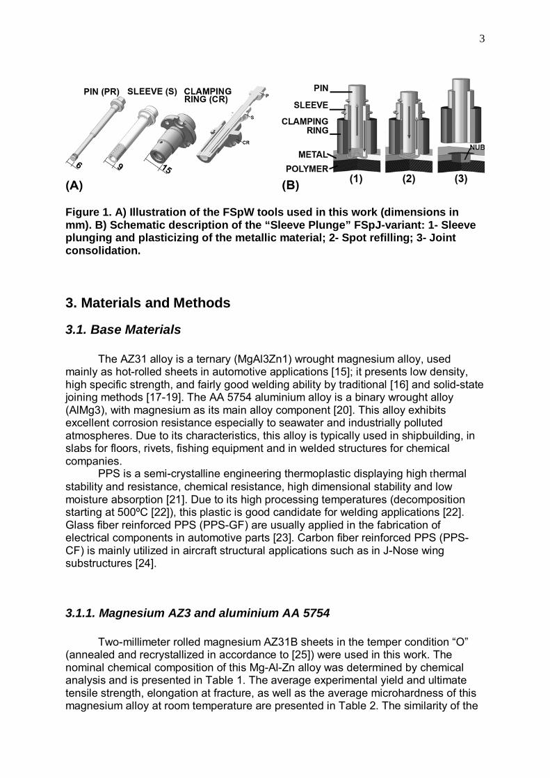
Friction Spot Joining (FSpJ) uses a three-piece non-consumable tool system comprising a clamping ring, a shoulder and a pin (Figure 1A). The tool components are mounted coaxially and can be rotated and moved in and out independently of each another. Analogous to friction spot welding of metals, FSpJ of polymer-metal structures process has two variants: the “Sleeve Plunge” (Figure 1B) and “Pin Plunge” (not depicted). In the “Sleeve Plunge” variant, the joining pieces are initially overlapped and clamped between a backing plate and the clamping ring, the metal piece on the top of the polymeric partner. Sleeve and pin begin to rotate in the same direction. Then the sleeve touches down on the upper surface of the metal piece producing frictional heat. Concomitantly, the sleeve is inserted into the metal piece and the pin retracted, forming an annular space (reservoir) (Figure 1B-1). During the sleeve plunging step, thermally plasticized metal is squeezed into the created reservoir.
At the end of the joining time, the sleeve is retracted to the surface of the metallic piece, while the pin pushes back the entrapped plasticized metallic material Figure 1B-2), refilling the key hole. The tool plunging depth is set in order to prevent damage to the polymeric piece; plunging takes place only in the metallic partner. This is intended to avoid or reduce the damage of fiber reinforcement, which can decrease the joint performance. Moreover, the plasticized metallic partner is deformed by the tool plunging movement. This creates a metallic “nub” on the surface the polymeric piece (Figure 1B-3). Frictional heat flows from the metallic to the polymeric partner by conduction and a thin layer of molten/softened polymer is created underneath the spot surface. In the case of reinforced plastics and polymer composites, the fiber network is slightly displaced to the edges of the spot. Finally, the joining head is retracted and the spot weld consolidates under pressure (Figure 1B-3). In the “Pin Plunge” variant (not depicted), the pin penetrates the metal piece while the sleeve is retracted. The other process steps are equivalent to the “Sleeve Plunge” variant.
3
Figure 1. A) Illustration of the FSpW tools used in this work (dimensions in mm). B) Schematic description of the “Sleeve Plunge” FSpJ-variant: 1- Sleeve plunging and plasticizing of the metallic material; 2- Spot refilling; 3- Joint consolidation.
3. Materials and Methods
3.1. Base Materials
The AZ31 alloy is a ternary (MgAl3Zn1) wrought magnesium alloy, used mainly as hot-rolled sheets in automotive applications [15]; it presents low density, high specific strength, and fairly good welding ability by traditional [16] and solid-state joining methods [17-19]. The AA 5754 aluminium alloy is a binary wrought alloy (AlMg3), with magnesium as its main alloy component [20]. This alloy exhibits excellent corrosion resistance especially to seawater and industrially polluted atmospheres. Due to its characteristics, this alloy is typically used in shipbuilding, in slabs for floors, rivets, fishing equipment and in welded structures for chemical companies.
PPS is a semi-crystalline engineering thermoplastic displaying high thermal stability and resistance, chemical resistance, high dimensional stability and low moisture absorption [21]. Due to its high processing temperatures (decomposition starting at 500ºC [22]), this plastic is good candidate for welding applications [22]. Glass fiber reinforced PPS (PPS-GF) are usually applied in the fabrication of electrical components in automotive parts [23]. Carbon fiber reinforced PPS (PPS-CF) is mainly utilized in aircraft structural applications such as in J-Nose wing substructures [24].
3.1.1. Magnesium AZ3 and aluminium AA 5754
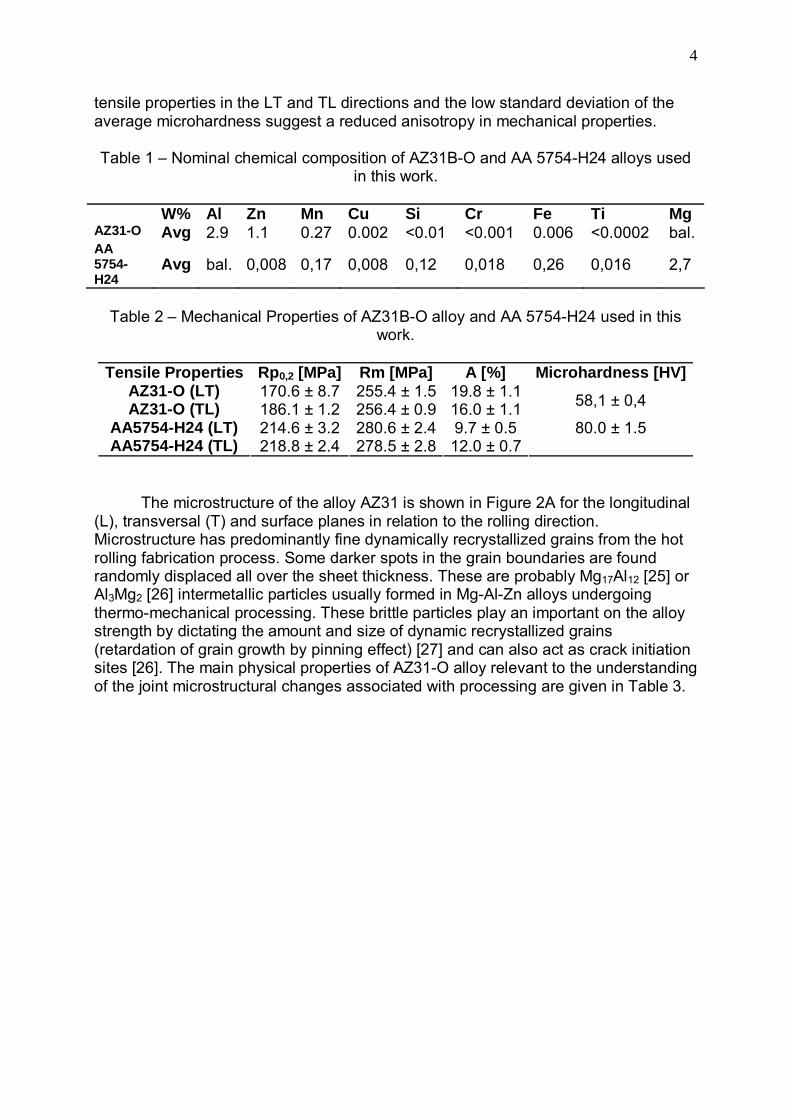
Two-millimeter rolled magnesium AZ31B sheets in the temper condition “O” (annealed and recrystallized in accordance to [25]) were used in this work. The nominal chemical composition of this Mg-Al-Zn alloy was determined by chemical analysis and is presented in Table 1. The average experimental yield and ultimate tensile strength, elongation at fracture, as well as the average microhardness of this magnesium alloy at room temperature are presented in Table 2. The similarity of the
4
tensile properties in the LT and TL directions and the low standard deviation of the average microhardness suggest a reduced anisotropy in mechanical properties.
Table 1 – Nominal chemical composition of AZ31B-O and AA 5754-H24 alloys used
in this work.
W% Al Zn Mn Cu Si Cr Fe Ti Mg AZ31-O Avg 2.9 1.1 0.27 0.002 <0.01 <0.001 0.006 <0.0002 bal. AA 5754-H24
Avg bal. 0,008 0,17 0,008 0,12 0,018 0,26 0,016 2,7
Table 2 – Mechanical Properties of AZ31B-O alloy and AA 5754-H24 used in this
work.
Tensile Properties Rp0,2 [MPa] Rm [MPa] A [%] Microhardness [HV]AZ31-O (LT) 170.6 ± 8.7 255.4 ± 1.5 19.8 ± 1.1AZ31-O (TL) 186.1 ± 1.2 256.4 ± 0.9 16.0 ± 1.1 58,1 ± 0,4
AA5754-H24 (LT) 214.6 ± 3.2 280.6 ± 2.4 9.7 ± 0.5 AA5754-H24 (TL) 218.8 ± 2.4 278.5 ± 2.8 12.0 ± 0.7
80.0 ± 1.5
The microstructure of the alloy AZ31 is shown in Figure 2A for the longitudinal (L), transversal (T) and surface planes in relation to the rolling direction. Microstructure has predominantly fine dynamically recrystallized grains from the hot rolling fabrication process. Some darker spots in the grain boundaries are found randomly displaced all over the sheet thickness. These are probably Mg17Al12 [25] or Al3Mg2 [26] intermetallic particles usually formed in Mg-Al-Zn alloys undergoing thermo-mechanical processing. These brittle particles play an important on the alloy strength by dictating the amount and size of dynamic recrystallized grains (retardation of grain growth by pinning effect) [27] and can also act as crack initiation sites [26]. The main physical properties of AZ31-O alloy relevant to the understanding of the joint microstructural changes associated with processing are given in Table 3.

5
Figure 1. A) 3D schematic representation of the microstructure of the AZ31-O base material (L: longitudinal, T: transversal, RD : Rolling Direction), B) 3D-illustration of the AA 5754-H24 aluminium alloy. C) Microstructure of PPS-GF (40% short fibers) in the extrusion direction (ED) and D) PPS-CF (5H satin, carbon-fiber woven reinforced) composites used in this work.
Table 3 – Physical Properties of AZ31B-O [25] and AA 5754-H24 [20] alloys used in
this work.
Liquidus Temp. [oC]
Solidus Temp.
[oC]
Insipient Melting
Temp. [oC]
Thermal Conductivity at 20 oC [Wm-1K-1]
Coefficient of Thermal Expansion within 20 to 200 oC
[mm-1K-1] AZ31-
O 632 566 532 76,9 26,8
Al 5754-H24
643 590 - 147 24
Two-millimeter rolled aluminium AA5754 sheets in the temper condition “H24” (strain hardened and partially annealed with the accomplishment of the tension release of 50% in accordance to [20]) were also selected in this work. The chemical composition of AA5754 alloy is presented in Table 1. The microstructure of the alloy AA5754-H24 is shown in Figure 2B for the longitudinal (L), transversal (T). Flattened

6
grains are present owing to the rolling process. The average experimental yielding and ultimate tensile strength, elongation at break, as well as the average microhardness of this aluminium alloy at room temperature are presented in Table 2. The aluminium plate is isotropic in both directions, like as for the case of the Mg-plates. The main physical properties of the Al 5754 are provided in Table 3
3.1.2. PPS-GF and PPS-CF reinforced composites 8 mm extruded plates of PPS, reinforced with 40% in volume of short glass
fibers (Techtron HPV, Quadrant Engineering Plastic Products, Germany), 2.1 mm and 3,4 mm PPS-CF woven-reinforced laminates (5H Satin, [(0.90)/(±45)]3/(0.90)] and [(0,90)/(±45)]5/(0,90)], 43% fiber reinforcement in weight, Tencate, Netherlands) were selected for the hybrid joints. Table 4 presents the main mechanical and physical properties of the composites studied. The thermal conductivity of the PPS composites comprises only 0,25% to 0,4% of the AZ31-O magnesium alloy, while their coefficients of linear thermal expansion are about twice the value observed for the AZ31-O alloy. The large difference in thermal conductivity will cause a very complex heating flow and temperature distribution during joining, while the different coefficients of linear thermal expansion can be detrimental to the joint mechanical strength. During cooling the composite tend to separate from the metal owing to thermal shrinkage. In order to avoid or reduce this phenomenon, mechanical clamping is applied during the joint consolidation.
Although the ultimate tensile strength of the PPS-CF laminate is much higher than of the PPS-GF composite (see Table 4) its “in plane” shear strength is only 119 MPa [29], about half of the AZ31 tensile strength. The decreased “in plane” shear strength of the laminate is a limiting factor for the joint lap shear performance, which is normally lower than the tensile strength of laminate composite. The general aspects of the microstructure of the PPS composites are presented in cross section macrographs depicted in Figure 2B and Figure 2C.
Table 4 – Room temperature mechanical and physical properties of PPS-GF and PPS-CF composites used in this work.
Rm [MPa]
A [%]
Glass Transition Temp. [oC]
Melting Temp.
[oC]
Thermal Conductivity at 23 oC [Wm-1K-1]
Coefficient of Thermal
Expansion within 23 to 150
oC [mm-1K-1] PPS-GF
61,0± 1,0
4,9 ±
0,6 90 [Ref. 28] 280
[Ref. 28] 0,30 [Ref. 28] 60 [Ref. 28]
PPS-CF
758 (warp)
755 (weft)
[Ref. 29]
3 [Ref. 29]
120 [Ref. 29] 280 [Ref. 29] 0,19 [Ref. 29] 52,2 [Ref. 29]

7
3.2. Experimental Procedure
3.2.1. Microscopic Analysis
Optical microscopy (OM) specimens were prepared from the base materials and cross-sections cut with a low-speed saw (Buehler, Germany) axially to the rivet length in the middle of joint. Materialographic specimens were embedded in low cure-temperature epoxy resin (Epoxicure, Buehler, Germany) to avoid any thermal changes in the polymeric partner, and grinded/polished by standard procedures. Chemical etching of the AZ31 alloy was performed with an ethanol solution of picric and acetic acids in water (8g picric acid, 5 mL acetic acid, 100 mL ethanol and 10 mL distilled water). Electrochemical etching was used to reveal the microstructure of the AA 5754-H4. Barker etching (5 mL HBF4 in 200 mL distilled water) was carried out with a voltage of 30 V and etching time of 120 seconds. OM was carried out under reflective non-polarized (DM IR microscope, Leica, Germany) and polarized light (PMG 3 microscope, Olympus, Germany); polymer-metal interfaces were also investigated under laser microscopy (VK-9700 microscope, Keyence, Japan).
3.2.2. Mechanical Testing
Vickers microhardness testing was performed in an automatic indenter (ZHV Zwick Roel, Germany) on embedded materialographic specimens under different conditions for the polymeric and metallic partners. For the AZ31, an indentation load of 200 gf (1.96 N) for 5s and a distance between the two consecutive indentations of 0.5 mm [30] was utilized. A load of 50 gf (0.49 N) with 15s of holding time (compensating for the visco-elastic behavior of this thermoplastic [31]) and 0.3 mm of indentation distance was selected to test the PPS composites
Base material and joint global mechanical strength was analyzed through lap shear testing according to DIN EN 10002 [32] (AZ31), DIN 53455 [33] (PPS-GF) and ASTM D 1002-05 [34] (overlap joints). Tensile and lap shear testing were run in a universal testing machine with a traverse speed of 2 mm/min at room temperature. Figure 3 presents the geometry of the overlaps joints selected for the evaluation of joint mechanical strength
Figure 3. Geometry of the lap shear testing specimens.

8
3.2.3. Thermal Measurements The process temperature was determined with an infrared camera (VarioTHERM camera, Jenoptik, Germany) set in the range of 200 - 500ºC, with a resolution of 256 x 256 pixels at 50Hz. Thermocouples (type K Cr-Ni, 0.5mm diameter) were embedded into the joining partners at five different positions, as illustrated in Figure 3.
Figure 4 . Diagram of positioning of the thermocouples selected for thermometric measurements: A-A` is the longitudinal section, parallel to the specimen length and B-B’ the transversal view.
3.2.4. Joining Procedure
Joints were produced in a friction spot welding equipment (Harms&Wende, Germany) equipped with a specimen clamping system (Figure 5) designed for the production of single lap joints . Threaded tools (Figure 1A) were fabricated out of electroslag remelted maraging warm-work steel 1.6358 (X2NiCoMo18-9-5). Prior to joining procedure, metallic specimens were ground with P1200 SiC paper to remove the natural oxide layer from the surface to be frictioned. Both joint partners were cleaned with acetone. The optimal range of joining parameters for AZ31 to PPS-GF, AZ31 to PPS-CF and AA 5754-H24 to PPS-CF joints is summarized in Table 5.
Figure 5. Schematic representation of the sample holder and clamping system for overlap joints.
9
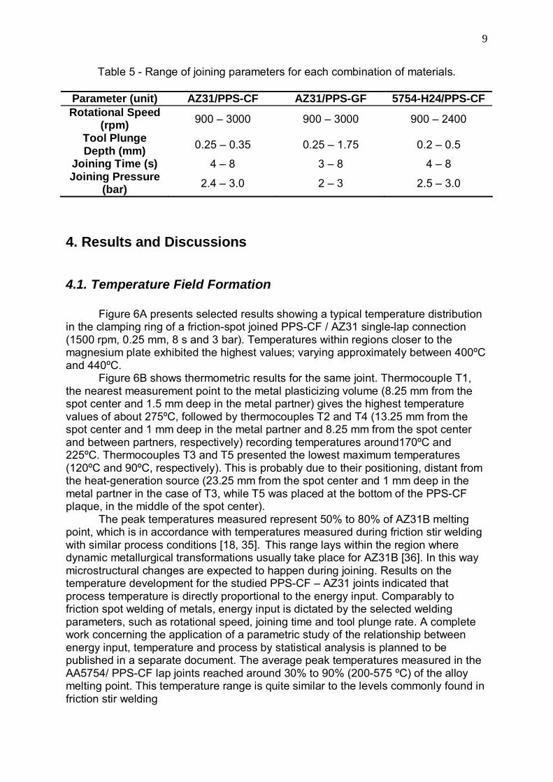
Table 5 - Range of joining parameters for each combination of materials.
Parameter (unit) AZ31/PPS-CF AZ31/PPS-GF 5754-H24/PPS-CF Rotational Speed
(rpm) 900 – 3000 900 – 3000 900 – 2400
Tool Plunge Depth (mm) 0.25 – 0.35 0.25 – 1.75 0.2 – 0.5
Joining Time (s) 4 – 8 3 – 8 4 – 8 Joining Pressure
(bar) 2.4 – 3.0 2 – 3 2.5 – 3.0
4. Results and Discussions
4.1. Temperature Field Formation
Figure 6A presents selected results showing a typical temperature distribution in the clamping ring of a friction-spot joined PPS-CF / AZ31 single-lap connection (1500 rpm, 0.25 mm, 8 s and 3 bar). Temperatures within regions closer to the magnesium plate exhibited the highest values; varying approximately between 400ºC and 440ºC.
Figure 6B shows thermometric results for the same joint. Thermocouple T1, the nearest measurement point to the metal plasticizing volume (8.25 mm from the spot center and 1.5 mm deep in the metal partner) gives the highest temperature values of about 275ºC, followed by thermocouples T2 and T4 (13.25 mm from the spot center and 1 mm deep in the metal partner and 8.25 mm from the spot center and between partners, respectively) recording temperatures around170ºC and 225ºC. Thermocouples T3 and T5 presented the lowest maximum temperatures (120ºC and 90ºC, respectively). This is probably due to their positioning, distant from the heat-generation source (23.25 mm from the spot center and 1 mm deep in the metal partner in the case of T3, while T5 was placed at the bottom of the PPS-CF plaque, in the middle of the spot center).
The peak temperatures measured represent 50% to 80% of AZ31B melting point, which is in accordance with temperatures measured during friction stir welding with similar process conditions [18, 35]. This range lays within the region where dynamic metallurgical transformations usually take place for AZ31B [36]. In this way microstructural changes are expected to happen during joining. Results on the temperature development for the studied PPS-CF – AZ31 joints indicated that process temperature is directly proportional to the energy input. Comparably to friction spot welding of metals, energy input is dictated by the selected welding parameters, such as rotational speed, joining time and tool plunge rate. A complete work concerning the application of a parametric study of the relationship between energy input, temperature and process by statistical analysis is planned to be published in a separate document. The average peak temperatures measured in the AA5754/ PPS-CF lap joints reached around 30% to 90% (200-575 ºC) of the alloy melting point. This temperature range is quite similar to the levels commonly found in friction stir welding

10
Figure 6. Temperature history measured by (A) Infrared thermography and (B) Thermometry for a AZ31/PPS-CF joint (1500 rpm, 0,25 mm, 8 s and 3 bar).
4.2. Microstructure and Local Joint Strength Figure 7 illustrates the surface view (Figure 7A, 7C and 7E) and cross-section macrographs (Figure 7B, 7D and 7F) of sound FSpJ joints on PPS-CF, PPS-GF /Mg AZ31 and PPS-CF/Al 5754 base materials (PPS-CF/AZ31 joint: 1500 rpm/0.25 mm/8 s/3 bar, PPS-GF/AZ31 joint: 3000 rpm/0.25 mm/8 s/2 bar and PPS-CF/Al5754 joint: 2400 rpm/0.5 mm/4 s/2.5 bar).
From the surface overview (Figure 7A, 7C and 7E) it is possible to identify the typical two concentric rings pattern left by the tool in the spot area. The internal ring consists of the stirred material, while the external ring comprises the impression left by the clamping ring. From the cross-sectional view in Figure 7B and 7F it can be observed the presence of a deformed metallic volume forming a “nub” inserted into the polymeric partner. This geometrical feature contributes to increased holding forces by mechanical interlocking in the direction of shear. In the case of PPS-CF composite, the formation of the nub is not accentuated, thanks to the high stiffness of the carbon-fiber weave (Figure 7D and 7F).
Figure 7. (A) Surface appearance of a PPS-GF/Mg AZ31 single lap joint (3000 rpm, 0.25 mm, 8 s, 2 bar); (B) Cross-sectional light optical macrograph of specimen in A; (C) Surface appearance of a PPS-CF/Mg AZ31 single lap joint (specimen from Figure 6); (D) Cross-section OM macrograph of specimen in C; (E) Surface appearance of a PPS-CF/Al5754 single lap joint (2400 rpm/0.5 mm/4 s/2.5 bar) and (F) Cross-section OM macrograph of specimen in E.
11
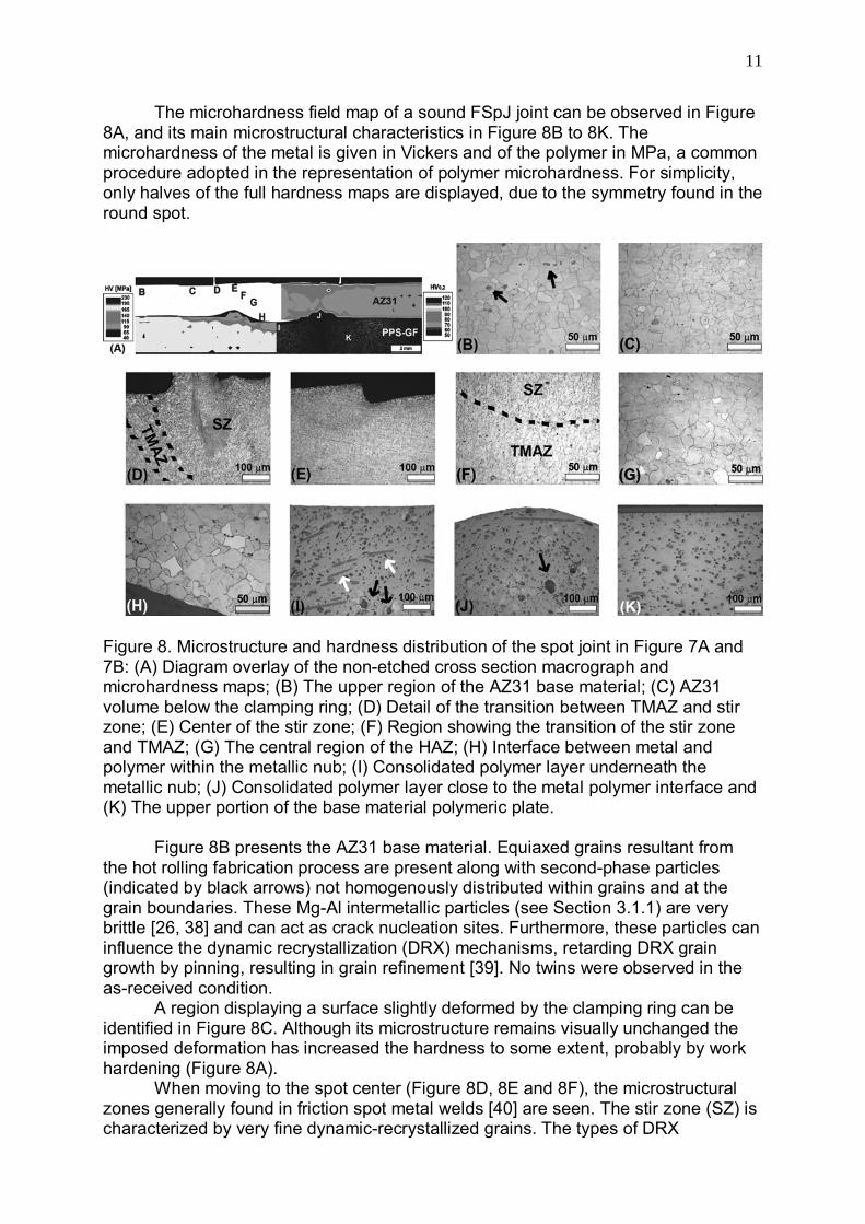
The microhardness field map of a sound FSpJ joint can be observed in Figure 8A, and its main microstructural characteristics in Figure 8B to 8K. The microhardness of the metal is given in Vickers and of the polymer in MPa, a common procedure adopted in the representation of polymer microhardness. For simplicity, only halves of the full hardness maps are displayed, due to the symmetry found in the round spot.
Figure 8. Microstructure and hardness distribution of the spot joint in Figure 7A and 7B: (A) Diagram overlay of the non-etched cross section macrograph and microhardness maps; (B) The upper region of the AZ31 base material; (C) AZ31 volume below the clamping ring; (D) Detail of the transition between TMAZ and stir zone; (E) Center of the stir zone; (F) Region showing the transition of the stir zone and TMAZ; (G) The central region of the HAZ; (H) Interface between metal and polymer within the metallic nub; (I) Consolidated polymer layer underneath the metallic nub; (J) Consolidated polymer layer close to the metal polymer interface and (K) The upper portion of the base material polymeric plate.
Figure 8B presents the AZ31 base material. Equiaxed grains resultant from
the hot rolling fabrication process are present along with second-phase particles (indicated by black arrows) not homogenously distributed within grains and at the grain boundaries. These Mg-Al intermetallic particles (see Section 3.1.1) are very brittle [26, 38] and can act as crack nucleation sites. Furthermore, these particles can influence the dynamic recrystallization (DRX) mechanisms, retarding DRX grain growth by pinning, resulting in grain refinement [39]. No twins were observed in the as-received condition.
A region displaying a surface slightly deformed by the clamping ring can be identified in Figure 8C. Although its microstructure remains visually unchanged the imposed deformation has increased the hardness to some extent, probably by work hardening (Figure 8A).
When moving to the spot center (Figure 8D, 8E and 8F), the microstructural zones generally found in friction spot metal welds [40] are seen. The stir zone (SZ) is characterized by very fine dynamic-recrystallized grains. The types of DRX
12
processes in hexagonal close-packed Mg alloys are continuous, CDRX (including twinning DRX [41, 42]) at moderate temperatures (250-400oC [43]) and discontinuous, DDRX at temperatures above 400oC [43].
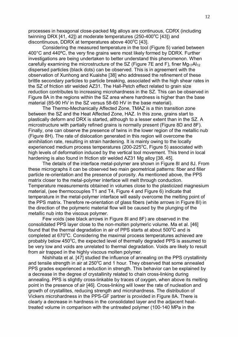
Considering the measured temperature in the tool (Figure 5) varied between 400°C and 440ºC, the very fine grains were most likely formed by DDRX. Further investigations are being undertaken to better understand this phenomenon. When carefully examining the microstructure of the SZ (Figure 7E and F), finer Mg17Al12 dispersed particles (black dots) can be observed. This is in agreement with the observation of Xunhong and Kuaishe [38] who addressed the refinement of these brittle secondary particles to particle breaking, associated with the high shear rates in the SZ of friction stir welded AZ31. The Hall-Petch effect related to grain size reduction contributes to increasing microhardness in the SZ. This can be observed in Figure 8A in the regions within the SZ area where hardness is higher than the base material (85-90 HV in the SZ versus 58-60 HV in the base material).
The Thermo-Mechanically Affected Zone, TMAZ is a thin transition zone between the SZ and the Heat Affected Zone, HAZ. In this zone, grains start to plastically deform and DRX is started, although to a lesser extent than in the SZ. A microstructure with partially refined grains is normally present (Figure 8D and 8F). Finally, one can observe the presence of twins in the lower region of the metallic nub (Figure 8H). The rate of dislocation generated in this region will overcome the annihilation rate, resulting in strain hardening. It is mainly owing to the locally experienced medium process temperatures (200-225oC, Figure 5) associated with high levels of deformation induced by the vertical tool movement. This trend in local hardening is also found in friction stir welded AZ31 Mg alloy [38, 45].
The details of the interface metal-polymer are shown in Figure 8I and 8J. From these micrographs it can be observed two main geometrical patterns: fiber and filler particle re-orientation and the presence of porosity. As mentioned above, the PPS matrix closer to the metal-polymer interface will melt through conduction. Temperature measurements obtained in volumes close to the plasticized magnesium material, (see thermocouples T1 and T4, Figure 4 and Figure 6) indicate that temperature in the metal-polymer interface will easily overcome the melting point of the PPS matrix. Therefore re-orientation of glass fibers (white arrows in Figure 8I) in the direction of the polymeric material flow will be caused by the plunging of the metallic nub into the viscous polymer.
Few voids (see black arrows in Figure 8I and 8F) are observed in the consolidated PPS layer close to the non-molten polymeric volume. Ma et al. [46] found that the thermal degradation in air of PPS starts at about 500oC and is completed at 670oC. Considering the maximal process temperatures achieved are probably below 450oC, the expected level of thermally degraded PPS is assumed to be very low and voids are unrelated to thermal degradation. Voids are likely to result from air trapped in the highly viscous molten polymer.
Nishihata et al. [47] studied the influence of annealing on the PPS crystallinity and tensile strength in air at 250oC and 1 hour. They observed that some annealed PPS grades experienced a reduction in strength. This behavior can be explained by a decrease in the degree of crystallinity related to chain cross-linking during annealing. PPS is slightly cross-linkable by traces of oxygen, when above its melting point in the presence of air [46]. Cross-linking will lower the rate of nucleation and growth of crystallites, reducing strength and microhardness. The distribution of Vickers microhardness in the PPS-GF partner is provided in Figure 8A. There is clearly a decrease in hardness in the consolidated layer and the adjacent heat-treated volume in comparison with the untreated polymer (100-140 MPa in the

13
consolidated layer versus 170 MPa in the base polymer). Therefore, this behavior may be explained in terms of a decrease in the original degree of crystallinity by cross-linking induced by thermal processing and originated during joint consolidation. Further investigations are in progress aiming to better explain this occurrence.
The microstructure of the joints on PPS-CF /AZ31, Al 5754 will be discussed in details in future publications. Preliminary results have shown that these joints have experienced similar microstructural changes as found in the PPS-GF/AZ31 joints (i.e. dynamic recrystallization and physical-chemical transformations in the PPS matrix).
4.3. Global Joint Strength
Lap Shear Testing (Section 3.1.5) was selected to investigate FSpJ joint’s static mechanical performance. Examples of selected shear force-displacement curves (PPS-CF/AZ31: 1950 rpm, 0.25 mm plunge depth, 8 s, 2.5 bar; PPS-GF/AZ31: 3000 rpm, 0.25 mm plunge depth, 8 s, 2 bar) are shown in Figure 9A. According to the present knowledge of the author, there is no available data in the literature addressing mechanical properties of overlap joints in PPS and AZ31. As a result of that an attempt was performed to compare FSpJ with the best shear strength results on polymer, composite/metal hybrid joints produced with different joining technologies and surface pre-treatments available in the literature. For comparison purposes, FSpJ joint ultimate forces were converted to ultimate shear stress through the adoption of a nominal welding area corresponding to the outer sleeve diameter of the FSpJ tool (Ф9 mm). This is a common procedure adopted in cases where the real joined area is not measurable. Figure 9B summarizes the current performance of FSpJ in comparison with available techniques. Table 6 sums up the main characteristics of the joints presented in Figure 9B.
Figure 9. (A) Example of force versus displacement curves for FSpW Mg AZ31/PPS-GF, PPS-CF joints; (B) Histogram showing average ultimate shear strength of selected FSpJ joints and available techniques (UW: Ultrasonic Welding, IW: Induction Welding, RW: Resistance Welding, FSSW: Friction Stir Spot Welding, AD: Direct Adhesive Bonding).
Although a direct comparison of FSpW with available literature data was not possible, important conclusions can be drawn, considering the observed similarities in joint geometry, testing procedures and fracture mechanisms in the coexisting joining techniques. A first observation is that FSpJ joints without surface pre-treatment displayed comparable or better ultimate tensile strengths compared to
14
literature (see as-received Ultrasonic and Induction welded specimens, Figure 9B). Secondly, FSpJ joints are even stronger than some joints produced with surface pre-treatment (compare as-received and surface-treated Induction, Resistance, Friction Stir Spot Welding and Adhesive Bonded joints). Thus an additional increase in the strength of FSpJ joints is expected to be accomplished by applying surface pre-treatments. Balle et al [50] and Velthuis and Mitschang [51] have shown, that simple mechanical surface pre-treatment on the metal component can improve the mechanical performance of polymer-metal overlap joints, owing to the creation of sufficient surface roughness, increasing micro-mechanical interlocking. Current investigations on the influence of surface treatments for the magnesium/PPS-composite FSp joints (to be published separately) have indicated an average increase of about 50% of the joint lap shear strength, when increasing the roughness of the magnesium partner by mechanical grinding from 0.75 μm to 3.45 μm.
Table 6. State-of-the-art in polymer-metal lap joints.
Joining Process Materials Surface Treatment Process Conditions Testing
Method Fracture Type Reference
FSpW Mg AZ31 / PPS-CF
Grinding SiC grid paper P1200 + acetone rinsing
1950 rpm, 0.25 mm plunge depth, 8 s,
2.5 bar DIN EN 10002
Mixed cohesive / adhesive
regime (composite)
-
FSpW Mg AZ31 / PPS-CF
Grinding SiC grid paper P1200 + acetone rinsing
3000 rpm, 0.25 mm plunge depth, 8 s, 2 bar DIN EN 10002
Mixed cohesive / adhesive
regime (polymer)
-
Ultrasonic Welding
AlMg3 (1 mm) / PA 66-CF (2mm) As-received
Vibration amplitude: 40 μm; axial force: 140 MPa; Energy:
2160 J
Single lap joints (single
specimens of 25 x 70 mm)
Cohesive (composite) [49]
Ultrasonic Welding
AlMg3 (1 mm) / PA 66-CF (2 mm)
Corundum blasting + HNO3-pickling
Vibration amplitude: 37-43 μm; axial force: 100-200 MPa; Energy: 1700-
2500 Ws
Single lap joints (single
specimens of 25 x 70 mm.
Overlap: 25 x 25 mm )
Cohesive (composite) [50]
Induction Welding
AlMg3 (1 mm) / PA 66-CF (2 mm)
Acetone wiping and
Corundum blasting + additional 100 μm PA 66
film
Welding Force: 0.5 MPa and 800 Hz DIN EN 1465
Mixed cohesive / adhesive
regime (composite)
[51]
Resistance Welding
Al 7075-T6 (3 mm) / PEI-CF
(3,14 mm)
Abrasion +degreasing+alkaline
cleaning+phosphoric acid anodization (PAA)
Power: 90 kW/m2; welding time: 10 min ASTM D-1002 Cohesive
(composite) [52]
Friction Stir Spot Welding
Al 5754 (2 mm) / PA 66 (1.6 mm)
Aluminum: as-received / Nylon heat treated in air at
125°C/ 24 hrs.
Tool: steel, shoulder Ф10 mm/pin Ф2.5 mm
Single lap joints (specimens: 25.4
x 100 mm. Overlap: 25.4 x
25.4 mm)
Cohesive (polymer) [53]
Adhesive Bonding
Ti 15-3 (1.6 mm) / PPS-GF
(2.5 mm). Adhesive: AF-
3109-2K
Ti: Sodium hydroxide anodization (SHA).
Composite: corundum blasting
Curing: 150 oC/ 60 min/ 350 KPa ASTM D-5868-95 Cohesive
(composite) [54]
The fracture surface analysis of the PPS-CF / AZ31 joint from Figure 9A is
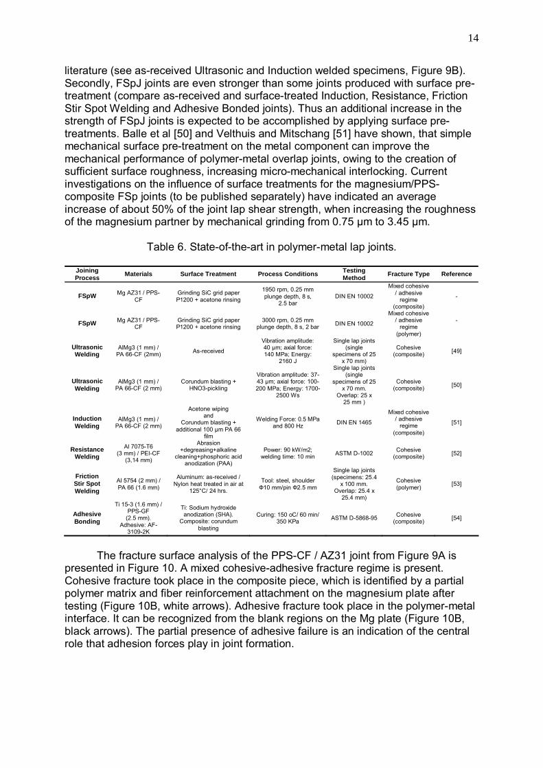
presented in Figure 10. A mixed cohesive-adhesive fracture regime is present. Cohesive fracture took place in the composite piece, which is identified by a partial polymer matrix and fiber reinforcement attachment on the magnesium plate after testing (Figure 10B, white arrows). Adhesive fracture took place in the polymer-metal interface. It can be recognized from the blank regions on the Mg plate (Figure 10B, black arrows). The partial presence of adhesive failure is an indication of the central role that adhesion forces play in joint formation.
15
Figure 10. (A) Overview of the fractured PPS-CF / AZ31 FSp lap joint in Figure 8. (B) Infrared micrograph of the central region in the spot area of the magnesium plate.
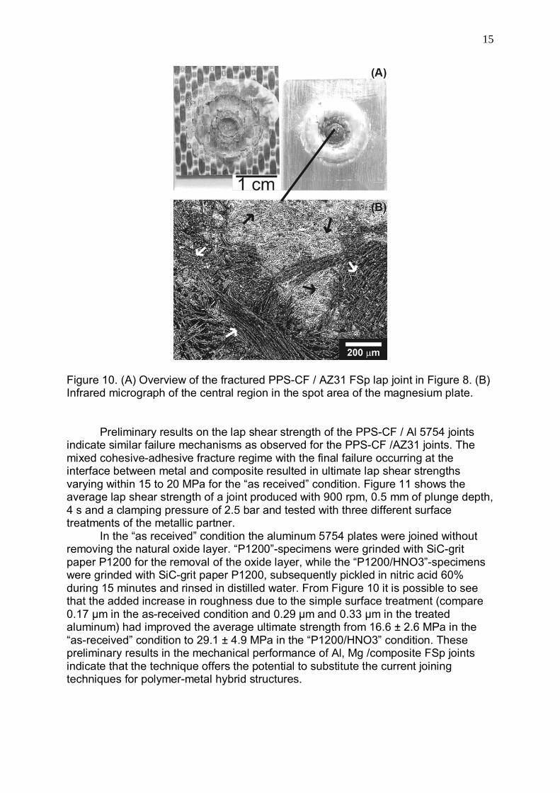
Preliminary results on the lap shear strength of the PPS-CF / Al 5754 joints indicate similar failure mechanisms as observed for the PPS-CF /AZ31 joints. The mixed cohesive-adhesive fracture regime with the final failure occurring at the interface between metal and composite resulted in ultimate lap shear strengths varying within 15 to 20 MPa for the “as received” condition. Figure 11 shows the average lap shear strength of a joint produced with 900 rpm, 0.5 mm of plunge depth, 4 s and a clamping pressure of 2.5 bar and tested with three different surface treatments of the metallic partner.
In the “as received” condition the aluminum 5754 plates were joined without removing the natural oxide layer. “P1200”-specimens were grinded with SiC-grit paper P1200 for the removal of the oxide layer, while the “P1200/HNO3”-specimens were grinded with SiC-grit paper P1200, subsequently pickled in nitric acid 60% during 15 minutes and rinsed in distilled water. From Figure 10 it is possible to see that the added increase in roughness due to the simple surface treatment (compare 0.17 μm in the as-received condition and 0.29 μm and 0.33 μm in the treated aluminum) had improved the average ultimate strength from 16.6 ± 2.6 MPa in the “as-received” condition to 29.1 ± 4.9 MPa in the “P1200/HNO3” condition. These preliminary results in the mechanical performance of Al, Mg /composite FSp joints indicate that the technique offers the potential to substitute the current joining techniques for polymer-metal hybrid structures.
16
Figure 11. Examples of the lap shear strength of a PPS-CF / Al 5754 FSp joint (900 rpm/ 0.5 mm of plunge depth/ 4 s/ clamping pressure of 2.5 bar) produced with different surface treatments of the metallic partner.
5. Quality, efficiency/productivity, environmental and work safety aspects The current analysis has shown that Friction Spot Joining offers the potential to fulfill the current limitations observed in the available joining techniques for polymer-metal hybrid structures. It was demonstrated in this work that the FSpJ is applicable for different classes of engineering materials, with high efficiency. Strong joints, displaying comparable or better performance than joints produced with concurrent techniques, could be produced with short joining cycles, simple and low cost commercially available equipment; there is no obligatory requirement of using very complex and expensive surface pre-treatments on the joining partners, although simple mechanical or acid pickling surface treatment may add an considerable improvement in joint strength. Being a friction-based joining technique FSpJ works with lower processing temperatures. Emissions are not generated, which make the process environmental friendly. Furthermore the higher level of energy conversion efficiency in comparison to fusion welding process, increases the economical attractiveness of this new technique for future industrial applications. Finally the availability of operation and safety procedures documentation provided by the equipment producer allows a precise and safer machine operation as well the utilization of robotic applications.
6. Conclusions and Final Remarks
The current study has demonstrated that friction spot joining can be successfully applied for joining magnesium and aluminum to thermoplastic composites. Achieved peak temperatures were within 0.5 – 0.80Tm of the AZ31B, 0.3 – 0.9Tm of the Al 5754 and within the range where the PPS structure is changed by annealing. In this way, metallurgical and polymer physical-chemical transformations have taken place during joining. Dynamic recrystallization (grain refinement) in the stir zone and thermal changes in the PPS structure in the consolidated zone, directly

17
influence the microhardness distribution (local strength) of FSpJ joints. These phenomena are still under investigation and further work will help to clarify the process/structure/properties relationships in FSpJ of polymer-metal hybrid structures. Although the bonding mechanisms of FSpJ are not yet well understood, there are strong indications that joining is accomplished by a mixed regime of surface mechanical interlocking (through micro and macro constraints related to the metallic nub) and adhesion between the metallic and consolidated polymeric layers, as well as direct partial fiber attachment on the metallic plate. Finally, short joining cycles, operation simplicity, availability of commercial equipment as well as good mechanical performance, makes FSpJ an alternative joining technology for polymer-metals hybrid structures.

18
Acknowledgements
The authors would like to thank A. Hoppe, for the preparation of metallographic specimens and C. Bueno and T. Rocha for the mechanical characterization and temperature analysis. The authors would like to acknowledge the financial support provided by the Helmholtz Association Germany (Grant: Young Investigator Group “Advanced Polymer-Metal Hybrid Structures”).

19
References [1] B. Reinhold, K. Angermann, in: W. Krenkel, Verbundwerkstoffe (Composites), Wiley-VCH GmbH & Co.KGaA, Weinheim, 2009, 27-38. [2] P. Juchmann, S. Wollf, in: K.U. Kainer, Magnesium, Wiley-VCH GmbH & Co.KGaA, Weinheim, 2004, 1006-1012. [3] A. Gavine, Dream team: an efficient test program is underway to create an efficient aircraft`, Aerospace Testing International, March, 2005, 39-43. [4] S.T. Peters, Handbook of Composites, second ed., Chapman & Hall, London, 1998, 115-128. [5] R.G.S. Barsoum, AMPTIAC-Quarterly, 7 (3) (2003), 55-61. [6] R. Stauber, in: W. Krenkel, Verbundwerkstoffe (Composites)’, Wiley-VCH GmbH & Co.KGaA, Weinheim, 2009, 12-26. [7] F. Faupel, R. Willecke, A. Thran, Mater. Sci. Eng. R., R22 (1998), 1-55. [8] R.W. Messler Jr., Assembly Automation, 20 (2) (2000), 118-128. [9] R.W. Messler Jr., J. Thermoplast. Compos. Mater., 17 (51) (2004), 51-75. [10] S.T. Amancio-Filho, J.F. dos Santos, Polym. Eng. Sci., 49 (8) (2009), 1461-1476. [11] C. Schilling, J.F. dos Santos, US Patent No. 6722556B2, (2004). [12] P.H.F. Oliveira, S.T. Amancio-Filho, J.F. dos Santos, E. Hage Jr., Mater. Letters, 64 (2010), 2098-2101. [13] S.T. Amancio-Filho, P.H.F. de Oliveira, C. Bueno, A. Hoppe, J.F. dos Santos, E. Hage Jr., Recent advances in joining of polymer and polymer-metal hybrid structures by friction-based spot welding techniques, Proceedings for ANTEC 2010, May 2010, Orlando World Center Marriott Resort & Convention Center, Orlando, Florida, USA. [14] S.T. Amancio-Filho, J.F. dos Santos, European Patent Application No. EP 09015014 (2009). [15] V. Kaese, L. Greve, S. Jüttner, M. Goede, S. Schumann, H. Friedrich, W. Holl, W. Ritter, in: K.U. Kainer (Ed.), Magnesium, Wiley-VCH GmbH & Co.KGaA, Weinheim, 2004, 949-954. [16] B.L. Mordike and T. Ebert, Mater. Sci. Eng., A, 302 (2001), 37-45. [17] J.A. Esparza, W.C. Davis, E.A. Trillo, L.E. Murr, J. Mater. Sci. Letters, 21 (2002), 917-920.

20
[18] L. Commin, M. Dumont, J.-E. Masse, L. Barrallier, Acta Mater., 57 (2) (2009), 326-334. [19] Q. Yang, S. Mironov, Y.S. Sato, K. Okamoto, Microstructure and Mechanical Properties of Friction Stir Spot Welded AZ31 Mg Alloy, 7th International Friction Stir Welding Symposium, May 2008, Awaji Yumebutai Conference Centre, Awaji Island, Japan. [20] ASM International: Handbook of Aluminium & Aluminium Alloys 3rd ed., USA (1996) p. 59 and 73-74. [21] H. Domininghaus, Die Kunststoffe und ihre Eigenschaften, 5th ed., Springer-Verlag, Berlin, 1998, 887-906. [22] L.A. Berglund, in: S.T. Peters (Ed.), Handbook of Composites, second ed., Chapman & Hall, London, 1998, 115-130. [23] J.A. Brydson, Plastics Materials, seventh ed., Butterworth-Heinemann, Oxford, 1999, 593-596. [24] P. Mitschang, M. Blinzler, A. Wöginger, Composites Science and Technology, 63 (2003), 2099-2110. [25] M.M. Avedesian, H. Baker, ASM Specialty Handook, Materials Park, ASM International, 1999, 78-79. [26] J. Yan, Z. Xu, Z. Li, L. Li, S. Yang, Scr. Mater., 53 (2005), 585-589. [27] S.W. Xu, N. Matsumoto, S. Kamado, T. Honma, N. Saito, Mater. Sci. Eng., A, 517 (2009), 354-360. [28] Techtron HPV PPS, ’Technical and data sheets’, Quadrant Engineering Plastics Products, Germany, 2007. [29] Cetex PPS, ‘Technical Data sheets’, Tencate Advanced Composites, Netherlands, 2009. [30] ASTM E384-992e1, Standard testing method for microindentation hardness of materials, ASTM International, USA, 2005. [31] F.J.B. Calleja, S. Fakirov, Microhardness of polymers, Cambridge University Press, Cambridge, 238, 2000. [32] DIN EN 10002 Part 1, Tensile testing of metallic materials – method of test at ambient temperature, DIN-Institut für Normung e.V., Berlin, Germany, 1991, 19. [33] DIN 53455, Prüfung von Kunststoffen, Zugversuch, DIN-Institut für Normung e.V., Berlin, Germany, 1981, 241-248.

21
[34] ASTM D 1002-05, Standard test method for apparent shear strength of single-lap-joint adhesively bonded metal specimens by tension loading (metal-to-metal), ASTM International (Beuth Verlag GmbH), Berlin, Germany, 2005, 5. [35] T. Nagasawa, M. Otsuka, T. Yokota, T. Ueki, in: H.I. Kaplan, J. Hryn, B. Clow (Eds.), Magnesium Technology 2000, The Minerals, Metals & Materials Society, Nashville, Tennessee, 2000, 383-387. [36] Y.V.R.K. Prasad, K.P. Rao, Advanced Engineering Materials, 9 (7) (2007), 558-565. [37]. L. Jin, D. Lin, D. Mao, X. Zeng, W. Ding, Mater. Lett., 59 (2005), 2267-2270. [38] W. Xunhong, W. Kuaishe, Mater. Sci. Eng., A, 431 (2006), 114-117. [39] S.W. Xu, N. Matsumoto, S. Kamado, T. Honma, Y. Kojima, Scr. Mater., 61 (2009), 249-252. [40] A.A.M. da Silva, J.F. dos Santos, T.R. Rosendo, F.D. Ramos, C.C.P. Mazzaferro, M.A.D. Tier, L. Bergmann, J.A.E. Mazzaferro, T.R. Strohaecker, Performance evaluation of 2-mm thick alclad AA2024 T3 aluminium alloy friction spot welding, Society of Automotive Engineering - SAE, 2007, paper No. 07ATC-103. [41] O. Sitdikov, R. Kaibyshev, T. Sakai, Materials Science Forum, 419-422 (2003), 521-526. [42] X. Yang, H. Miura, T. Sakai, Materials Science Forum, 419-422 (2003), 515-520. [43] S.M. Fatemi-Varzaneh, A. Zarei-Hanzaki, H. Beladi, Mater. Sci. Eng., A, 456 (2007), 52-57. [44] J.L. Murray, in: A.A. Nayeb-Hashemi, J.B. Clark (Eds.), Phase diagrams of binary magnesium alloys, Metals Park, ASM International, 1988, 17-34. [45] C.I. Chang, X.H. Du, J.C. Huang, Scr. Mater., 57 (2007), 209-212. [46] C.-C.M. Ma, H.-C. Hsia, W.-L Liu, J.-T. Hu, J. Thermopl. Compos. Mater., 1 (1998), 39-49. [47] N. Nishihata, T. Koizumi, Y. Ichikawa, T. Katto, Polym. Eng. Sci., 38 (3) (1998), 403-408. [48] D. Tabor, Journal of the Institute of Metals, 79 (1951), 149-166. [49] F. Balle, G. Wagner, D. Eifler, Advanced Engineering Materials, 11 (2009), 35-39 [50] F. Balle, G. Wagner, D. Eifler, in: M. Pohl (Ed.), Werkstoffprüfung 2004, Werkstoff-Informationsgesellschaft GmbH, Frankfurt, 2004, 329-334. [51] R. Velthuis, P. Mitschang, S. Emrich, M. Kopnarski, Journal of Thermoplastic Composite Materials, 22 (6) (2009), 767-801.

22
[52] C. Ageorges, L. Ye, Journal of Thermoplastic Composite Materials, 14 (2001), 449-475. [53] K.N. Balakrishnan, H.T. Kang, P.K. Mallick, SAE Technical Paper Series, SAE, 2007, Paper No. 2007-01-1701. [54] P. Molitor, T. Young, Int. J. Adhes. Adhes., 22 (2002), 101-107.