friction and contact resistance for low ......friction and contact res1 stance for low -speed...
TRANSCRIPT

N A S A T E C H N I C A L NOTE NASA - e.
TN -
FRICTION AND CONTACT RESISTANCE FOR LOW-SPEED GALLIUM-LUBRICATED SLIDING ELECTRICAL CONTACTS OF BERYLLIUM I N VACUUM
by John S. Przybyszewski
Lewis Research Center Clevelund, Ohio
N A T I O N A L A E R O N A U T I C S A N D S P A C E A D M I N I S T R A T I O N W A S H I N G T O N , D. C. M A R C H 1970
https://ntrs.nasa.gov/search.jsp?R=19700011326 2020-04-25T01:13:29+00:00Z
TECH LIBRARY KAFB, NM
1. Report No. 3. Recipient's Catalog No. 2. Government Accession No.
NASA TN D-5706 4. Ti t le and Subti t le FRICTION AND CONTACT RESISTANCE 5. Report Date
FOR LOW-SPEED GALLIUM-LUBRICATED SLIDING March 1970
ELECTRICAL CONTACTS OF BERYLLILJM IN VACUUM 6. Performing Organization Code
7. Authods) 8. Performing Organization Report No. John S. P rzybyszewski E-5375
9. Performing Organization Name and Address
Lewis Resea rch Cen te r National Aeronautics and Space Administration Cleveland, Ohio 44135
12. Sponsoring Agency Name and Address
National Aeronautics and Space Administration Washington, D. C. 20546
1 1 . Contract or Grant No.
- 13. Type of Report and Period Covered
Technical Note
14. Sponsoring Agency Code
IS. Supplementary Notes
16. Abstroct
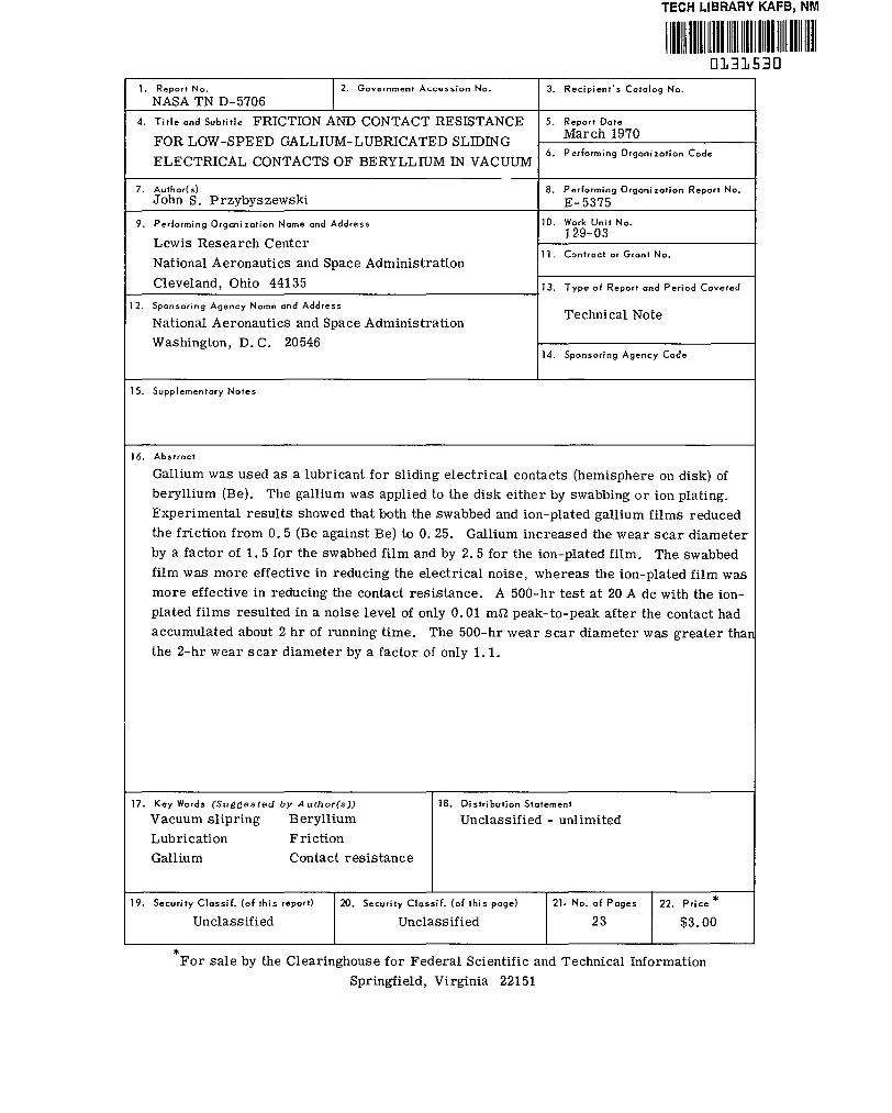
Gallium was used as a lubricant for s l iding e lectr ical contacts (hemisphere on d isk) of beryll ium (Be). The gall ium was applied to the disk either by swabbing or ion plat ing. Experimental resul ts showed that both the swabbed and ion-plated gal l ium f i lms reduced the f r ic t ion f rom 0.5 (Be against Be) to 0. 25. Gal l ium increased the wear scar d iameter by a fac tor of 1 .5 for the swabbed f i lm and by 2 .5 for the ion-plated f i lm. The swabbed f i lm was more effect ive in reducing the e lectr ical noise , whereas the ion-plated f i lm was more effective in reducing the contact resistance. A 500-hr test at 20 A dc with the ion- plated f i lms resulted in a noise level of only 0.01 mS2 peak-to-peak after the contact had accumulated about 2 hr of running t ime. The 500-hr wear scar d iameter was g rea te r tha~ the 2 -hr wear scar d iameter by a fac tor of only 1.1.
17. Key Wards ( S u g g e s t e d b y Aufhor (s ) ) 18. Distribution Statement
Vacuum s l ipr ing Beryl l ium Lubricat ion Fr ic t ion
Unclassified - unlimited
Gal l ium Contact res is tance
19. Security Classif. (of this report) 22. Pr ice * 21. No. of Pages 20. Security Classif. (of this page)
Unclassified $3.00 23 Unclassified
e - F o r sale by the Clear inghouse for Federal Scient i f ic and Technical Information
Springfield, Virginia 22151


FRICTION AND CONTACT RES1 STANCE FOR LOW -SPEED GALLIUM-LUBRICATED
SLIDING ELECTRICAL CONTACTS OF BERYLLIUM IN VACUUM
by John S. Przybyszewski
Lewis Research Center
SUMMARY
Gallium was used as a lubricant for 4.76-millimeter-radius beryllium hemispheres running against the flat surface of 50.8-millimeter-outside-diameter beryllium disks at a sliding speed of 132 mill imeters per minute (1 rpm) in a vacuum of tor r under a 100-gram load. The duration of each screening run was 2 hours. Gallium was applied to the disk only by two methods: (1) swabbing, when the gallium did not wet the beryl- l ium surface and (2) ion plating, when the gallium did wet the beryllium surface. One 500-hour endurance run was made using the ion-plated gallium film and a constant con- tact current of 20 amperes dc.
The results of the experiments showed that the swabbed gallium film did not reduce the coefficient of friction from that of beryllium against beryllium (0.5) until the contact had accumulated about 40 minutes of running time, whereupon the friction decreased gradually to 0.25. The ion-plated gallium film reduced the friction to 0.25 within 10 minutes, where it remained throughout the test. The swabbed gallium film displayed the higher average contact resistance (1.05 mS2) and the lower noise level (0.05 mS2 peak- to-peak after 50 min of running time). The ion-plated gallium film displayed the lower contact resistance (0.3 mS2) and the higher noise level (0.4 mS2 peak-to-peak). The presence of gall ium increased the wear scar diameter over that of an unlubricated beryllium-against-beryllium sliding contact by a factor of 1. 5 for the swabbed film and by a factor of 2.5 for the ion-plated film. The 500-hour test at 20 amperes dc with the ion-plated gallium film, after about 2 hours of running time, resulted in the lowest noise level of all of the tests (0.01 mS2 peak-to-peak). The average contact resistance was about 0.9 milliohm. The 500-hour wear scar diameter was greater than the 2-hour wear scar d iameter ( same f i lm) by a factor of only 1.1.

INTRODUCTION
A sliding-electrical-contact problem of current interest is the transmission of sub- stantial amounts of direct current electrical power from stationary to rotating compo- nents that operate at low speeds (less than 132 mm/min or 1 rpm) in an ultrahigh vacuum environment (refs. 1 and 2). The simplest solution to this problem is the sliding- element slipring (conventional brush and ring configuration). Since gross sliding is the principal feature of this device, an effective lubricant must be used to reduce friction and wear to acceptable values and to insure a long useful life. The selection of a suitable lubricant for this type of application is a very difficult task because an electrical current must pass through the lubricant film. Sliprings, therefore, impose a unique requirement on a lubricant. This requirement is that the electrical resistivity of the lubricant film be low to reduce the electrical losses in the film. Because of this unique requirement, a lubricant for use in sliding-electrical-contact applications cannot be selected solely on the basis of its effectiveness in reducing friction and wear alone. The ideal electrical contact lubricant must have the properties of providing low friction and wear while simul- taneously maintaining a nearly constant, continuous, low electrical resist ivity across a slipring fabricated from some low-resistivity metal. These problems are discussed more fully in the BACKGROUND section.
The objective of this investigation was to determine the effectiveness of gallium as a lubricant, in vacuum, for sliding electrical contacts of beryllium.
A sliding electrical contact consisted of a 4.76-millimeter hemispherically tipped rod (brush) sliding against the flat surface of a 50.8-millimeter-outside diameter disk (slip- ring). All experiments were performed in ultrahigh vacuum (10-l' t o r r ) at a sliding speed of 132 mill imeters per minute (1 rpm). The frictional force and ac electrical con- tact resistance o r contact voltage drop were measured continuously during each experi- ment. Al l sliding electrical contacts were loaded prior to energizing with an electrical current.
In those experiments where direct current was used, the hemisphere (brush) polarity was positive and the disk (slipring) w a s negative, as read by a conventional multimeter.
The duration of each screening experiment was 2 hours. An endurance experiment using the film that displayed the lowest contact resistance during the screening experi- ment was run continuously for 500 hours at 20 amperes dc to evaluate the possibliities of using the gallium-lubricated beryllium-against-beryllium slipring for long-term vacuum applications.
BACKGROUND
The contact resistance of a clean contact is inversely proportional to the actual area
2

of contact (ref. 3.). A large actual area of metal-to-metal contact is desirable to obtain a low electr ical res is t ivi ty across an electrical contact for the purpose of reducing elec- t r ical losses . A metal-to-metal sliding electrical contact (no lubricant) would permit a large amount of power to be transmitted with a minimum number of sliprings and with low electrical losses. However, the large coefficients of friction, extreme rates of wear, and great probability of seizure exhibited by the usual metal-to-metal sliding con- tact make this mode of operation unacceptable for long-term operation.
The ideal case, from the point of view of friction and wear, would be complete sepa- ration of the sl iding surfaces by a low-shear-strength lubricant film. If complete sepa- ration of the sl ipring surfaces is a requirement for low friction and wear and a large ac- tual a r e a of metallic contact is a requirement for low electrical losses, the sl ipring ap- pears to require two modes of. operation that are contradictory (complete separation and metal-to-metal contact at the same t ime). These two modes of operation may possibly be reconciled by means of a very low-shear-strength metall ic f i lm. For the lowest pos- sible shear strength, the metallic film should be a liquid at the operating temperature of the slipring.
The use of a metallic film lubricant that is a liquid at the operating temperature of the slipring might offer another advantage in addition to a lower shear strength. If the liquid metallic film lubricant wets the surfaces of the sl ipring materials, the actual area of metal-to-metal contact will be greater than that area of contact formed in the absence of a liquid metallic film. Ordinarily, the actual area of contact between two materials in physical contact is directly proportional to load and is inversely proportional to flow p res su re o r yield strength (ref. 4). This actual area of contact will be much smaller than the apparent area of contact because the load is borne by relatively few asperi t ies on each surface. Because of the immobility of the surface material , there is little con- formity between the two surfaces in contact. If a liquid metal that wets the contact ma- te r ia l s is placed on the surfaces, the conformity between the two surfaces in contact is much better because of the mobility of a liquid. Consequently, the actual area of contact will now be more nearly equal to the apparent area of contact and, hence, more current can be carried.
On the basis of the preceding discussion, the following characteristics of a possible sliding-electrical-contact lubricant for vacuum use in high-current situations can now be summarized:
(1) The lubricant must have a high electrical conductivity to reduce contact resis- tance to a very low level.
(2) The lubricant must provide acceptable values of friction and wear. (3) The lubricant should wet the contact surfaces s o that it will remain in the contact
area during sl iding and maintain continuous separation of the sliding surfaces. Wetting increases the actual area of contact and, hence, the current-carrying capacity.
3

(4) The lubricant must have a low vapor pressure to reduce the loss of the lubricant by evaporation over a period of time and to minimize potentially troublesome reconden- sation on nearby surfaces. A low-vapor-pressure material would allow a higher contact operating temperature, thereby permitting higher current densities without undue loss of the lubricant.
An elemental metal that best satisfies these requirements is gallium (refs. 5 to 7). Other low-melting-point (<30° C) elemental metals (e. g., mercury) can be eliminated because of their high vapor pressures, which would prohibit their use in ultrahigh vacuum.
Some of the physical properties of gallium are summarized in table I (ref. 5).
TABLE I. - SOME PROPERTIES OF GALLIUM
[Data from ref. 5.1
~~~~~ ~
Melting point, OC Boiling point, O C
Temperature for vapor pressure of 1 mm Hg, OC
Surface tension a t 30' C, dynes/cm (N/cm) Thermal conductivity, (cal)(sec)/(cm2)('C)(cm)
Volume resistivity at 46.1' C, pohm-cm Resistance to oxidation
((J)(sec)/(cm2)(0C)(cm))
Density at 29.8' C, g/cm 3
29.75 1983 1315
235 ( 2 . 3 5 ~ 1 0 - ~ ) 0.07 to 0.09 (0.3 to 0.37)
28.4 Good, even at red heat, after initial oxide film is formed
6.09
Gallium has been previously investigated as a lubricant primarily for 52100 s tee l and 440-C stainless steel in both vacuum and argon (refs. 6 and 7). The resul ts of these experiments showed that gallium can be an effective lubricant for these mater ia ls at room temperature.
Although gallium has many attractive properties for possible use as a vacuum sliding-electrical-contact lubricant, it is generally considered to be a very corrosive material and will attack many of the metals commonly used in sliding electrical contacts. At high temperatures, the corrosion problem is very serious. Experiments have shown that the amount of corrosive wear caused by the use of gallium as a lubricant on 440-C stainless s teel in sliding friction experiments at high temperatures approaches the amount of wear in the unlubricated condition (ref. 6). Corrosion and corrosive wear may, perhaps, be the most serious problem encountered in the use of gallium as a lubri- cant, especially in a vacuum where heat rejection is a problem. However, there are metals - particularly, tungsten, tantalum, and beryllium - that are res is tant to corro- sive attack by gallium at moderate to high temperatures (450' to 800' C) (refs. 8 and 9).
4

If these metals are used in conjunction with gallium as a lubricant at lower temperatures, it may be concluded that corrosive wear will be much less and that such a combination of materials may be satisfactory for use as a vacuum sliding electrical contact provided that the values of the coefficient of friction and electrical noise level are acceptable.
Although beryllium is generally considered to be a toxic metal, it was chosen as the slipring and brush material for the initial gallium lubrication investigation because of its lower electrical resist ivity. In addition, sliding friction experiments in vacuum have a l so shown that beryllium has good friction and wear properties (refs. 10 to 12).
SPECIMEN PREPARATION
Instrument grade (1-400) beryllium was used for all experiments. All specimens were machined to an 8 r m s finish. The gallium was applied to one face of the beryllium disks by two different methods:
(1) By means of a cotton swab, after previously warming both the disk and the gal- lium
(2) By means of ion plating with the use of the techniques and apparatus described in reference 13
All gallium films were applied to the disk specimens only.
APPARATUS
The ultrahigh vacuum system and drive mechanism are described in detail in refer- ence 14.
Contact Resistance Measurement - Screening Experiments
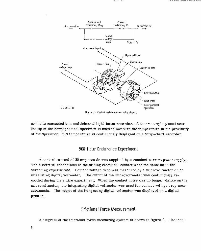
A commercial four-terminal ac milliohmmeter having full-scale ranges from 1 milli- ohm to 1000 ohms was used to measure the contact resistance in the screening experi- ments. The current used was 33 milliamperes rms at 40 hertz. The electrical connec- tions to the specimens are shown in figure 1. One current and one voltage lead from the milliohmmeter are connected separately to opposite sides of a copper cup containing liq- uid gallium. The disk specimen is mounted on the shaft by means of insulating glass- mica bushings and is secured with a locknut. A ring machined into the remaining end of the copper spindle and partially immersed in the gallium completes the electrical circuit to the disk specimen. The remaining current and voltage leads are connected directly to the electrically insulated hemispherical specimen (brush). The output of the milliohm-
5
Gallium well Contact dc c u r r e n t in RGW resistance, R, dc current out
- 0 y./n * I t
Contact * : voltage __
drop RGIV << Rc
dc current input %
Contact
r Liquid gall ium
r Copper cup Copper r ing 7 ,' \
'\ - Hemispherical CD-10411-17 specimen
Figure 1. - Contact resistance measuring circuit
meter is connected to a multichannel light-beam recorder. A thermocouple placed near the tip of the hemispherical specimen is used to measure the temperature in the proximity of the specimen; this temperature is continuously displayed on a strip-chart recorder.
500-Hour Endurance Experiment
A contact current of 20 amperes dc was supplied by a constant current power supply. The electrical connections to the sliding electrical contact were the same as in the screening experiments. Contact voltage drop was measured by a microvoltmeter or an integrating digital voltmeter. The output of the microvoltmeter was continuously re- corded during the entire experiment. When the contact noise was no longer visible on the microvoltmeter, the integrating digital voltmeter was used for contact vnltage drop mea- surements. The output of the integrating digital voltmeter was displayed on a digital printer.
Frictional Force Measurement
A diagram of the frictional force measuring system is shown in figure 2. The insu-
6

Mounting bracket 7, ,-Pivot arm I ./ ,-- 1 . \
. .- I
- "
J \
\ \
Flexural pivot
,- Load applied at
a
I I +', ,,,, this p int
Cantilever beam 7,
Rider specimen-J ' ILDisk mounting screw
Figure 2 - Frictional force measurement assembly.
lated block in which the hemispherical specimen is mounted is affixed to the f r e e end of a small cantilever beam. The amount of beam displacement, which is porportional to the frictional force, is sensed by a capacitance probe mounted normal to the direction of bending. The output of the probe control is connected to a light-beam recorder channel calibrated in grams force.
RESULTS AND DISCUSSION
Bery l l ium Aga ins t Bery l l ium
Initially, beryllium was run against beryllium to establish some reference data that could be used to determine the effectiveness of gallium as a lubricant for beryllium. The resulting coefficient of friction, electrical contact resistance, and electrical noise (peak- to-peak value of resistance) are shown in figure 3. The coefficient of friction, after s tar t ing at a value of 0.6, dropped to an average value of 0.5 after several moments of operation and remained at this value throughout the remainder of the experiment. The value of the coefficient of friction of 0.5 is in general agreement with the value obtained in other experiments (ref. 10) for sliding polycrystalline beryllium against polycrystalline beryllium in vacuum.
7

i ” ”
c J 0 10 20 30 40 50 60 80 100 120
Running time, min
Figure 3. -Coefficient of friction and contact resistance against running time for dry 4.76-millimeter- radius beryllium hemisphere running on dry beryllium disk. Load, 100 grams; speed, 132 milli- meters per minute (1 rpm); vacuum, l0-l1torr; duration of run, 2 hours; contact current, 33 milliamperes (40 Hz).
The contact resistance was quite erratic (3 to 10 m a ) , and the contact noise was quite high (2 to 10 mi2 peak-to-peak) during the first 10 minutes of operation. These wiae- ranging values of contact resistance and high peak-to-peak values of contact noise are be- lieved to be the result of the breaking up of the thin, high-resistance oxide film normally present on the beryllium surface. The contact resistance remained somewhat erratic throughout much of the 2-hour experiment. However, as the experiment accumulated about 90 minutes of running time, the contact resistance appeared to level out to a value of about 2. 5 milliohms. The contact noise, although somewhat less than that displayed during the first few moments of operation, also remained high throughout much of the ex- periment. The contact noise did, however, seem to stabilize to a value of about 2 milli- ohms peak-to-peak concurrently with the stabilization of the contact resistance. These results indicate that the contact zone is undergoing rapid changes in composition and con- tact area during approximately the first 90 minutes of operation. During this period, the wear t rack is still rapidly widening, and much oxide film is still being broken up on both s ides of the wear track and around the wear scar on the mating hemisphere. Periodi- cally, some of this high-resistance oxide film must have passed through the contact zone and caused the observed peaks of high resistance.

(a) No lubrication. Running time, 2 hours. (b) Swabbed gallium film on disk only. Running time, 2 hours.
IC) Ion-plated gallium film on disk only. Running time, 2 hours. Id) Ion-plated gallium lilm on disk only. Running time, 500 hours at 20 amperes dc.
Figure 4. - Wear scars on tips of beryllium hemispheres after running against a dry beryllium disk and beryllium disks with swabbed or ion-plated gallium films. Vacuum, 10-l’ torr; load, 100 grams; speed, 132 millimeters per minute (lrpm).
A photomicrograph of the unlubricated beryllium hemisphere wear scar is shown in figure 4(a). The wear scar is l e s s than 1/4 millimeter in diameter. This low wear (despite the fact that no lubrication was used), coupled with a relatively moderate coef- ficient of friction, indicates that beryllium itself has good friction and wear properties. It is possible that, after a short break-in period in vacuum to disrupt and disperse the surface oxides, unlubricated beryllium might make an acceptable vacuum sliding elec- trical contact for certain applications. Operation in vacuum is to be preferred s ince it would prevent reformation of surface oxides and ensure a metal-to-metal contact that would have a lower contact resistance and a lower noise level. The phenomenon of cold welding, which might be expected in an unlubricated condition with beryllium, would not be a problem as reference 10 indicates.
9

Bery l l i um Against Bery l l i um With Swabbed Ga l l ium F i lm
For the first attempt at gallium lubrication of the beryllium-against-beryllium sliding electrical contact, gallium was applied to the surface of a beryllium disk by swabbing the gallium on the surface in an endeavor to form a continuous film. However, no amount of swabbing would cause the gallium to wet the beryllium surface. The gallium would s im- ply ball up and roll around on the surface when prodded by the swab. A photograph of the beryllium disk with the swabbed gallium film is shown in figure 5(a). A photomicrograph
(a) Swabbed gal l ium film. (b) Ion-plated gallium film.
Figure 5. - Beryl l ium disks with two types of gallium films.
of the appearance of the beryllium surface with a swabbed gallium film is shown in fig- u r e 6. The gallium does not form a continuous film on the surface but exists as pools o r blobs. The nonwetting action of gallium undoubtedly is influenced by the presence of a film of oxide on the beryllium surface, since the swabbing was done in the atmosphere. If it is possible to obtain a clean beryllium surface, wetting by the gallium might occur.
The results of a 2-hour sliding friction experiment using a beryllium disk swabbed with a gallium film running against a beryllium hemisphere in vacuum are shown in fig- u re 7. The data show that the initial coefficient of friction f is characterist ic of beryl- lium sliding against beryllium, unlubricated (f = 0.5, s e e fig. 3). However, after about 40 minutes of running time, the average coefficient of friction decreased to about 0.25. A photomicrograph of a portion of the wear track on the beryllium disk after a 2-hour run
10

Figure 6. -Appearance of surface of 50.8-millimeter-outside-diameter beryllium disk after swabbing with liquid gallium and wiping excess from surface.
Highest peak [ Average Lowest peak
Where peaks are not shown, noise i s less than 0.2 mR peak-to-peak
1 I I I 0 10 20 M 40 50 60 80 100 120
h
Running time, m in
Figure 7. -Coefficient of friction and contact resistance against running time for 4.76-millimeter- radius beryll ium hemisphere running on beryll ium disk with l iquid gall ium swabbed o n surface. Load, 100 grams; speed, U2 millimeters per minute (1 rpm); vacuum, 10-l1 torr; duration of run, 2 hours; contact current, 33 milliamperes (40 Hz).
11

Figure 8. - Enlarged view of portion of wear track on surface of beryllium disk swabbed with gallium fi lm and run against 4.76-millimeter-radius beryllium hemisphere. Sliding speed, 132 millimeters per minute (1
rPm); load, 100 grams; vacuum, torr; duration of run, 2 hours.
(fig. 8) shows that some gallium is present in the grooves of the wear track and has ap- peared to wet some of the surfaces. These observations explain the reason for the de- crease in the coefficient of friction after about 40 minutes of running time. This decrease is believed to be caused by the trapping of some of the randomly located microscopic pools of gallium, on the beryllium surface, in the grooves of the developing wear track. Since the beryllium surfaces in the wear track are cleansed of some of the oxide film by abrasion, the gallium wets some of the wear track. The two sliding beryllium surfaces a r e now partially separated by a gallium film, and the coefficient of friction decreases
12

because of the lower shear strength of the gallium film. The wear scar on the tip of the beryllium hemisphere run against the beryllium disk
with the swabbed gallium film (fig, 4(b)) was larger than the wear scar on the unlubrica- ted hemisphere by a factor of 1.5. The increased wear is attributed to the presence of gallium in the contact zone. Evidently, the gallium, once it comes in contact with a clean beryl l ium surface, increases the wear by corrosion. The gall ium corrosion resistance generally ascribed to beryllium might be the result of the presence of a thin protective fi lm of beryllium oxide on the beryllium surface, since many corrosion experiments were performed in air (ref. 8). It is interesting to note that beryllium oxide is quite resistant to attack by gallium up to 1000° C (ref. 5). The photomicrograph also shows a drop of gallium that has adhered to the tip of the hemisphere. This is evidence that the gallium has also partially wetted the tip of the hemisphere.
The contact resistance and noise for this combination of mater ia ls is shown in fig- u r e 7. The initial contact resistance, as with the unlubricated beryllium, was high (>9 m a ) but began to stabilize more rapidly (1.5 m a at 5 min) than the unlubricated beryllium (2.5 mS1 at 90 min). The contact noise again stabilized concurrently with the contact resistance and was less than 0.07 milliohm peak-to-peak for the remainder of the 2-hour experiment. Toward the end of the experiment, thenoise lessened somewhat, dropping to less than 0.05 milliohm peak-to-peak. The contact noise was s o remarkably low that the contact resistance trace showed a straight l ine on the light-beam recorder.
It must be noted that there was no change in the coefficient of friction as the contact resistance and noise stabilized at about 5 minutes of running time. Conversely, the con- tact resistance and noise did not change as the coefficient of friction decreased from 0.5 to 0. 25 at about 40 minutes into the run. One possible speculation for this behavior is that liquid-gallium contact was established between the two surfaces in about 5 minutes, but the liquid-gallium film did not support any of the load at this time and, hence, did not appreciably affect the coefficient of friction. The beryll ium surfaces supported the load (f = 0.5, fig. 7) until at about 40 minutes accumulated running time the gallium became trapped in the contact zone. The load then gradually shifted to the liquid-gallium film, which resulted in lubrication by the gallium and thereby a reduction in the coefficient of friction (f = 0.25, fig. 7).
Bery l l ium Aga ins t Bery l l ium Wi th lon-P la ted Ga l l ium F i lm
Since a continuous gallium film could not be obtained on a beryllium surface by swab- bing (possibly because the beryllium surface was contaminated with oxides), ion plating of the gallium was attempted. One outstanding feature of ion plating is that the beryllium surface can be cleaned by ion bombardment with the working gas (usually argon) prior to ion plating with the desired fi lm material .
13
A beryllium disk was sputter cleaned for 30 minutes to remove the surface contami- nation prior to ion plating with gallium from a tungsten-boat source. Examination of the beryllium disk after ion plating revealed that the gallium had completely covered the sur- face. The wetting of the beryllium surface by the gallium was qualitatively determined by simply wiping the outside diameter with a paper towel. This wiping action showed that the gallium film was continuous and that it adhered to the beryllium surface. The gallium film behaved in much the same manner as the wiping of a hot, conventional lead-tin solder on a clean copper surface. A photograph of the ion-plated gallium specimen is shown in figure 5(b). The dimpled appearance was a result of both the specimen position during plating (face down) and the large amount of gallium that evaporated. This disk was run in a vacuum sliding friction test exactly as it came out of the ion-plating apparatus.
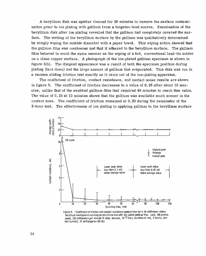
The coefficient of friction, contact resistance, and contact noise results are shown in figure 9. The coefficient of friction decreases to a value of 0.25 after about 10 min- utes, unlike that of the swabbed gallium film that required 40 minutes to reach this value. The value of 0.25 at 10 minutes shows that the gallium was available much sooner in the contact zone. The coefficient of friction remained at 0. 25 during the remainder of the 2-hour test. The effectiveness of ion plating in applying gallium to the beryllium surface
.75
.50
.25
0
10
8
6
4
2
0
- Off scale
Highest peak Average Lowest peak
t t I Lower peak value less than 0.1 mR less than 0.05 mR below average value below average value
Lower peak value
-
7 1 J G r x - I I h I Y - 7 - 7 10 20 M 40 50 60 80 100 120
-11
Runn ing time, m in
Figure 9. -Coefficient of friction and contact resistance against time for 4.76-millimeter-radius beryl l ium hemisphere running on beryll ium diskwith ion-plated gall ium fi lm. Load, 100 grams; speed, 132 mil l imeters per minute (1 rpm); vacuum, torr; duration of run, 2 hours; con- tact current, 33 milliamperes (40 Hz).
14

~
is apparent in the contact resistance data of figure 9. The 10-minute value is about 0 .7 milliohm, whereas the 10-minute value for the swabbed gallium film is about 1.25 milliohms , a difference of 0.55 milliohm.
The contact resistance appears to stabilize at a value of about 0.3 milliohm after about 70 minutes of running time. The electrical noise of the ion-plated gallium film was higher throughout the entire test than the electrical noise of the swabbed gallium film at 5 minutes of running time (figs. 7 and 9). The higher noise level of the ion-plated gallium film is believed to be caused by the greater amount of gallium and, hence, a grea te r amount of gallium oxide on the beryllium surface. The difference between the amounts of gallium on the ion-plated surface and on the swabbed surface can be seen by comparing figures 5(a) and (b). The less noisy swabbed film existed as microscopic pools o r blobs on the surface (fig. 6). Consequently, much less gallium would be present in the sliding path. The oxide could therefore be more rapidly dispersed, and the contact noise could stabil ize in a much shorter period of t ime. Figure 7 shows that it does. It appears , then, that an excessive amount of gallium on the surface will degrade the initial noise performance for a longer period of time. However, as the sliding electrical contact lubricated with excessive gallium accumulates running time, its noise performance should also improve and stabilize. The data to be presented in the next section i l lustrate this point.
The wear scar diameter obtained with the ion-plated gallium film was larger than that obtained with the swabbed gallium film by a factor of about 1.65 (fig. 4(c)). The in- c rease in wear is attributed to the fact that the ion-plated gallium film was available much sooner and in greater quantities (film was continuous) than the swabbed gallium film.
Beryllium Against Beryllium With lon-Plated Gallium Film
Run 500 Hours at 20 Amperes Direct Current
The ion-plated gallium film was chosen for the 500-hour endurance test at 20 am- peres dc because it showed the lowest contact resistance of all the specimens tested in the 2-hour screening tests. The same ion-plated specimen used for the 2-hour run was used for the 500-hour run. The 500-hour test was run in a new wear track with a new beryllium hemisphere. The coefficient of friction, contact resistance, and contact noise data for the 500-hour test are shown in figure 10. Some contact voltage drop data are presented in f igure 11. Initially, a current of only 5 amperes could be applied to the con- tact because the contact resistance was very high for the first five revolutions (5 min) of the contact (fig. lO(a)). This behavior was not considered unusual because initially high resistances were observed in all the other tests. After this 5-minute contact break-in period, the contact current was increased to 20 amperes. The hemispherical specimen !
15

0 h I
Highest peak Average Lowest peak
Where either highest or lowest peak ip not shown, it is wi th in 0.1 mQ of average value
(a) Initial contact current, 5 amperes dc; contact current for remainder of run, 20 amperes dc.
10 - I I
I I
I I I I !
I I I I
I
I I
I I Automatic shutoff I p- activated as contact
I I - resistance reached 5 mR I
0 1 Actual shutdown "L(
8- I
6 -
4 - I iL;;;;2;Io I
I 0 A
1 1 I I I I A 1
I I
85 90 96 96 1N-I 110 120 130 140 " 30000 R u n n i n g m e , m i n
(b) Contact c u r r e n t 20 amperes dc.
Figure 10. -Coefficient of friction and contact resistance against time for 4.76-millimeter-radius beryllium hemisphere running against beryllium flat ion plated with gallium. Load, 100 grams; sliding speed, 132 millimeters per minute (1 rprn); vacuum, 10-11 torr; duration of run, 500 hours.
16

Number of readings (same
scale for each column)
0 2 4 6 8 I I I I I
10 I
.900L .01W 285 308 340 436
Running time, hr
Figure 11. - Distribution of digital contact voltage drop measurements for gallium- lubricated beryllium-against-beryllium sliding electrical contact. Sliding speed, 132 mill imeters per minute (1 rpm); constant current, 20 amperes dc; vacuum, 10-11 torr. Each distribution consists of 50 samples (sampling rate, 45 sampleshin) made at number of hours shown.
temperature rose rapidly to around 60' C, where it stabilized. The contact resistance appeared to stabilize at a value around 1.2 milliohms after 15 minutes of running time. The contact noise stabilized within 0. 2 milliohm peak-to-peak concurrently with the con- tact res is tance (fig. 10(a)). The contact, after initially showing high contact resistance and noise, showed only minor variations in contact resistance from 15 to 90 minutes of running time. However, during the same period, there were wide variations in the con- tact noise values.
A moment after 90 minutes of running time, the contact resistance and contact noise increased sharply and tripped the automatic shutoff mechanism (set at 5 mS2 contact re- sistance). The test was interrupted for a period of 1 hour while an equipment check was made. On restarting the test, the contact noise was very high but decreased rapidly to a value within 0.2 milliohm peak-to-peak. The contact resistance gradually fell to about 1 milliohm during the first 15 minutes of the restart period and remained at approxi- mately this value during the remainder of the 500-hour test (fig. 10(b)).
After a few hundred hours operating time, contact noise was below the range of the equipment in use, and an integrating digital voltmeter-printer combination was used to measure the contact voltage from about 285 to 500 hours. Portions of these data are
17
shown in figure 11. The time at which the readings were taken is shown at the bottom of each column of data. The contact voltage is shown on the ordinate. The length of the l ines at a particular value on the ordinate indicates the number of times that reading oc- curred during a 1.1-minute sampling period. The scale for the number of readings ap- pears at the top of each column and is the same for each column (e. g . , at 293 h r of run- ning. time, a contact voltage of 0.01828 V was printed out 10 times during the 1.1-min sampling period). A1 though the population is small, the plot shows a distribution that can give an indication of the contact noise and a probable value of contact resistance at the time indicated. The data in figure 11 show 'that the variation in the contact voltage drop is generally in the range of 200 to 250 microvolts (0.010 to 0.012 mS2) during most of the running time. The data also show that the contact resistance is slowly decreasing as t ime increases.
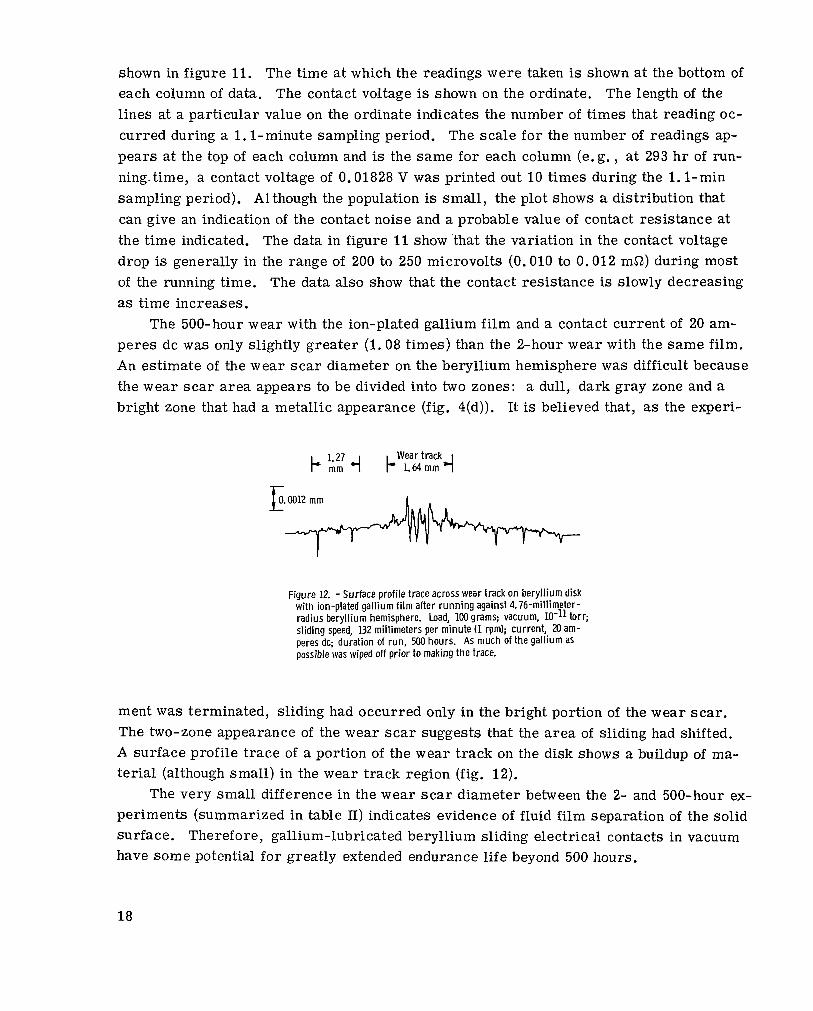
The 500-hour wear with the ion-plated gallium film and a contact current of 20 am- peres dc was only slightly greater (1.08 times) than the 2-hour wear with the same film. An estimate of the wear scar diameter on the beryllium hemisphere was difficult because the wear scar a rea appears to be divided into two zones: a dull, dark gray zone and a bright zone that had a metallic appearance (fig. 4(d)). It is believed that, as the experi-
Figure 12. - Surface profile trace across wear track on beryllium disk with ion-plated gallium f i l m after running against 4.76-millimeter- radius beryllium hemisphere. Load, 100 grams; vacuum, torr; sliding speed, 132 millimeters per minute (1 rpm); current, 20 am- peres dc; duration of run, 500 hours. As much of the gallium as possible was wiped off prior to making the trace.
ment was terminated, sliding had occurred only in the bright portion of the wear scar . The two-zone appearance of the wear scar suggests that the area of sliding had shifted. A surface prof i le t race of a portion of the wear track on the disk shows a buildup of ma- terial (although small) in the wear track region (fig. 12).
The very small difference in the wear scar diameter between the 2- and 500-hour ex- periments (summarized in table II) indicates evidence of fluid film separation of the solid surface. Therefore, gallium-lubricated beryllium sliding electrical contacts in vacuum have some potential for greatly extended endurance life beyond 500 hours.
18

TABLE II. - SUMMARY O F RFSULTS OF BERYLLIUM-AGAINST-BFRYLLIUM
SLIPRING RUNNING DRY AND WITH GALLIUM LUBRICATION
[Sliding speed, 132 mm/min (1 rpm); vacuum, lo-'' torr: load, 100 g.]
r Slipring material Beryllium brush against beryllium slipring
Gallium ion plated on slipring surface
Gallium ion plated on slipring surface
Lubricant None ;allium swabbed )n slipring iurface
NO Yes Surface wetted Yes
33 mA r m s 40 Hz
~
5 A dc 20 A dc
Slipring current 33 mA rms 40 Hz
Coefficient of friction at
10 min 60 min 500 h r
Average contact re- sistance, mf2, a t
10 min 60 min 500 h r
0.48 . 4 a
0.25 .25
"""""
0.25 .25 .25
3.5 2. 2
0.7 . 3
"""""
3 . 0 a t 5 A . 3 5 a t 20 A 0.9 a t 20 A
1.25 1.05
"""""
2. 5 . 4
"""""
Contact noise, mf2, peak- to-peak a t
10 min 60 min 500 h r
Brush wear scar diameter, mm
6 . O a t 5 A 0 .5 a t 20 A I. 01 a t 20 A
3.0 1 . 5
"""""
<O. 07 <. 05
"""""
0.19 0.29 0.48 0.52
Running t ime, hr 1 2 2 500
COMPARISON BETWEEN NOISE LEVELS OF PRESENTLY USED ELECTRICAL BRUSH
MATERIALS USING MOLYBDENUM DISULFIDE ( M o S ~ ) A S LUBRICANT
AND THOSE USING GALLIUM AS LUBRICANT
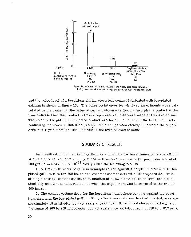
A comparison between the noise levels of two commonly used brush materials (silver-molybdenum disulfide, ref. 15, and silver-copper-molybdenum disulfide, ref. 16)
19
Contact noise, I.I V, peak-to-peak
1 1 n 250 c 0 V
Slipring 0 Silver Silver Beryll ium with ion-
plated gal l ium f i lm
20 500
Brush Contact dc current, A
Silver+loS2 Silver-copper-MoS2 Beryllium 0.032 75
Running time, hr 226 (ref. 15)
700 (ref. 16)
Figure 13. -Comparison of noise levels of two widely used combinations of slipring materials with beryll ium slipring lubricated with ion-plated gall ium.
and the noise level of a beryllium sliding electrical contact lubricated with ion-plated gallium is shown in figure 13. The noise resistances for all three experiments were cal- culated on the basis that the value of current shown was flowing through the contact at the time indicated and that contact voltage drop measurements were made at this same time. The noise of the gallium-lubricated contact was lower than either of the brush compacts containing molybdenum disulfide (MoS2). This comparison clearly illustrates the superi- ority of a liquid metallic film lubricant in the area of contact noise.
SUMMARY OF RESULTS
An investigation on the use of gallium as a lubricant for beryllium-against-beryllium sliding electrical contacts running at 132 millimeters per minute (1 q m ) under a load of 100 grams in a vacuum of torr yielded the following results:
1. A 4.76-millimeter beryllium hemisphere ran against a beryllium disk with an ion- plated gallium film for 500 hours a t a constant contact current of 20 amperes dc. This sliding electrical contact continued to function a t a low electrical noise level and a sub- stantially constant contact resistance when the experiment was terminated at the end of 500 hours.
2. The contact voltage drop for the beryllium hemisphere running against the beryl- lium disk with the ion-plated gallium film, after a several-hour break-in period, was ap- proximately 18 millivolts (contact resistance of 0 . 9 m a ) with peak-to-peak variations in the range of 200 to 250 microvolts (contact resistance variation from 0.010 to 0.012 m a ) .
20
3. The coefficient of friction for the beryllium hemisphere running against the beryl- lium disk with the ion-plated gallium film averaged 0.25 during the entire 500-hour run.
4. The diameter of the wear spot on the tip of the beryllium hemisphere after the 500-hour run was 0. 5 mill imeter, which was only slightly greater (1.08) than the diam- e te r of the wear spot after the 2-hour run using the same ion-plated film on the disk only.
5. A comparison of the wear scar d iameter on the hemispherical specimens after a 2-hour run without lubrication and with a gallium film on the disk only showed that the presence of the gallium increased the wear by a factor of 1.5 for the swabbed gallium film and by a factor of 2.5 for the ion-plated gallium film.
6. A l l the beryllium-against-beryllium sliding electrical contacts displayed peaks of high resistance during the first 5 to 30 minutes of each experiment. The variation in contact resistance for all the beryllium-against-beryllium sliding electrical contacts, after the initial break-in peridd, was less than 5 milliohms peak-to-peak.
Lewis Research Center, National Aeronautics and Space Administration,
Cleveland, Ohio, November 19, 1969, 129-03.
REFERENCES
1. Anon. : Aerospace Electronic Systems Technology. NASA SP-154, 1967.
2. Anon. : Multi-Kilowatt Solar Cell Power: Its Critical Technology and Hardware De- velopment. Radio Corp. of America (NASA CR-94551), 1967.
3. Holm, Ragnar: Electric Contacts Handbook. Third ed., Springer-Verlag, 1958.
4. Bowden, F. P. ; and Tabor, D. : The Friction and Lubrication of Solids. Clarendon Press, Oxford, 1950.
5. Hampel, Clifford A . , ed. : Rare Metals Handbook. Second ed., Reinhold Publ. Co., 1961.
6. Kuczkowski, Thomas J. ; and Buckley, Donald H. : Friction and Wear of Low-Melting Binary and Ternary Gallium Alloy Films in Argon and in Vacuum. NASA T N D-2721, 1965.
7. Buckley , D. H. ; and Johnson, R. L. : Gallium-Rich Films as Boundary Lubricants in A i r and in Vacuum to lo-’ mm Hg. ASLE Trans . , vol. 6, no. 1, Jan. 1963, pp. 1-11.
21

8. Udy, Murray C. ; Shaw, Homer L. ; and Boulger, Francis W. : Propert ies of Beryl- lium. Nucleonics, vol. 11, no. 5, May 1953, pp. 52-59.
9. Filyand, M. A. ; and Semenova, E. I. : Trace Elements and Light Elements. Vol. 1 of Handbook of the Rare Elements. Boston Technical Publ. , 1968.
10. Buckley, Donald H. ; and Johnson, Robert L. : Friction and Wear of Hexagonal Metals and Alloys as Related to Crystal Structure and Lattice Parameters in Vacuum. ASLE Trans . , vol. 9, no. 2, Apr. 1966, pp. 121-135.
11. Buckley, Donald H. : Effect of Orientation on Friction Characterist ics of Single- Crystal Beryllium in Vacuum (10-l' Torr). NASA TN D-3485, 1966.
12. Bucklev, Donald H. : Effect of Recrystallization on Frict ion Propert ies of Some Metals in Single-Crystal and Polycrystalline Form. NASA TN D-4143, 1967.
13. Spalvins, Talivaldis; Przybyszewski, John S. ; and Buckley, Donald H. : Deposition of Thin Films by Ion Plating on Surfaces Having Various Configurations. NASA TN D-3707, 1966.
14. Przybyszewski, John S. : Stress-Strain Behavior of Cold-Welded Copper-Copper Mi- crojunctions in Vacuum as Determined from Electrical Resistance Measurements. NASA TN D-4743, 1968.
15. Clauss, Francis J. : Lubrication of Ball Bearings and Slip Rings Under High Vacuum. Lubrication in Space. Warren A. Salmon and Henry Scammell, eds., Baird Atomic, Inc. and Arthur D. Little, Inc., 1963, pp. 41-76.
16. Clauss, Francis J. : Electrical Transmission Components for a Large Aerospace En- vironmental Chamber. Rep. 2-68-64-1 Lockheed Missiles and Space Co. (AEDC TR-65-40, DDC No. AD-457 356), Feb. 1965.
22