frequency disturbance recorder (fdr) installation guide - power it...
TRANSCRIPT

1
Power Information Technology (FNET) Lab Dr. Yilu Liu ([email protected]), Director Department of Electrical Engineering and Computer Science University of Tennessee, Knoxville 511 Min Kao Building Knoxville, TN 37996-2100 Phone: 865-974-4129 http://powerit.utk.edu
Frequency Disturbance Recorder (FDR) Installation
Guide
Revised: August 13, 2012
Generation II Frequency Disturbance Recorder (FDR)

` 2
Contents Hardware checklist ............................................................................................... 3
FDR Installation preparation ................................................................................. 3
Installation Procedure ........................................................................................... 4
Using the FDR ...................................................................................................... 4
Internal Moxa device configuration using its administrator software .................... 7
Troubleshooting ................................................................................................. 16
Frequently Asked Questions .............................................................................. 17
Appendix A: FDR Data Packet Description ........................................................ 20

` 3
Hardware checklist
FDR (Frequency Disturbance Recorder)
GPS antenna
Power cord for FDR
Ethernet cable
FDR Installation preparation
The first step in getting your FDR up and running is to pick a suitable location for the hardware. Beyond the obvious need for power and Ethernet connections, the system needs to be placed such that the GPS antenna can acquire a good signal. Handle the unit with care as it is very fragile.
The GPS antenna should be placed such that it has an unobstructed view of a large part of the sky’s horizon. Try to find a room that has a good view of the horizon. Usually, higher rooms in the building will get better reception than those at lower floors. Adjacent buildings can cause problems by reflecting the GPS signals. Once you’ve found an appropriate location, install the antenna. The best place is outside a window, away from overhangs and other obstructions. Secure the antenna using non-metallic tape, if necessary. If the antenna has to be put inside of a room, put it as close to the window as possible, as shown in Figure 1.
Figure 1: Antenna placement inside window We have found that the signal inside a window is sufficient most of the time, though this is usually a trial-and-error endeavor. However, windows with low emissivity (“low-e”) glass are generally not acceptable. Also, make sure to place the antenna with the black, curved surface facing toward the sky (i.e., the flat face should be on the bottom).
` 4
It is also important to locate the FDR away from magnetic sources such as personal computers and televisions. The LCD is very sensitive to magnetic fields and might not function properly if it is located too close to one of these devices.
Installation Procedure
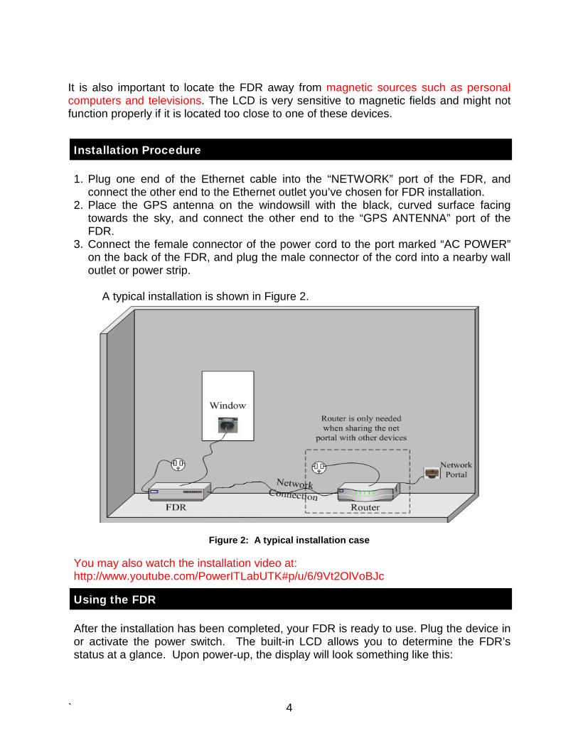
1. Plug one end of the Ethernet cable into the “NETWORK” port of the FDR, and connect the other end to the Ethernet outlet you’ve chosen for FDR installation.
2. Place the GPS antenna on the windowsill with the black, curved surface facing towards the sky, and connect the other end to the “GPS ANTENNA” port of the FDR.
3. Connect the female connector of the power cord to the port marked “AC POWER” on the back of the FDR, and plug the male connector of the cord into a nearby wall outlet or power strip.
A typical installation is shown in Figure 2.
Figure 2: A typical installation case
You may also watch the installation video at: http://www.youtube.com/PowerITLabUTK#p/u/6/9Vt2OlVoBJc
Using the FDR
After the installation has been completed, your FDR is ready to use. Plug the device in or activate the power switch. The built-in LCD allows you to determine the FDR’s status at a glance. Upon power-up, the display will look something like this:

` 5
Welcome to FNET! Please wait…
Initializing… Acquire… After powering on the FDR, please allow some time for the GPS system to initialize and lock onto the satellites. The device requires a minimum of four satellites for the GPS system to initialize. After initialization, the system can operate with a minimum of only one satellite. When setting the FDR up in a new location, the acquisition process might take several hours. Subsequent restarts will not take nearly as long provided the device is not moved to a new location. If the FDR is able to receive the GPS signal correctly, you should see the number of GPS satellites in use displayed on the LCD as shown in Figure 3. Once the GPS connection has been established, a “done!” message will appear on the LCD. After initializing, the FDR will begin collecting data. The LCD will display the current measurement, where “f” is frequency and “U” is AC voltage. Under normal circumstances, the LCD display will appear something like what is shown in Figure 3.
05/20/10 09:59:59 05f = 60.0002 U = 119.832
Current date(mm/dd/yy)
Current time(hh/mm/ss)
Number of satellites locked
Frequency(Hz)
Voltage(Volts)
Figure 3: LCD display
There are three indicator LEDs on the front panel as shown in Figure 4.

` 6
PWR NETPPS
Power On/Off indicator
GPS receiver per second pulse indicator
Network Connection indicator
Figure 4: Indication LEDs Under normal operating conditions, the PWR LED should be solid yellow, the PPS LED should flash once every second, and the NET LED will continuously flash at a rate of nearly six times per second. As long as the GPS signal remains stable, the FDR will continue collecting data.
• If the GPS signal is lost, the number of locked-on satellites will display “00” on the LCD.
• If the network is not physically connected, the NET LED will be dark. • If the network is physically connected, but there is no pathway between the FDR
and server, the NET LED will triple flash for one second and then pulse for the following second.
The FDR does not have any battery backup. A power loss will not damage the unit, however, it will simply reinitialize upon power-up. When an FDR is not working properly due to GPS signal loss, please wait until it has locked on the satellites again. For network connection problems, please ensure that the Ethernet cable and router are working properly. Although rare, the internal Ethernet device will sometimes reset itself, which will cause the network connection to fail. Please check Chapter 5 for the internal Ethernet device configuration instructions. Before modifying the configuration, try to power off and on the unit to restore normal function.

` 7
======================================================== The following section describes how to configure the Device Server. Since the system has been pre-configured before shipping, there is usually no need to read this part unless you want to change the network settings.
Internal Moxa device configuration using its administrator software
The data coming out of the FDR’s CPU is transferred via a serial port connection. The FDR contains a device used to convert the data from serial transmission to Ethernet transmission, the Moxa NE-4100T. The Moxa device is the only piece of hardware that must be manually configured to work with your particular site. Installing Network Enabler Administrator Using the software package “neadm_setup_Ver2.11_Build_07082213,” you can install Network Enabler Administrator on your Windows-based computer. 1. Once the setup program starts running, click on Next when the Welcome window
opens to proceed with the installation.
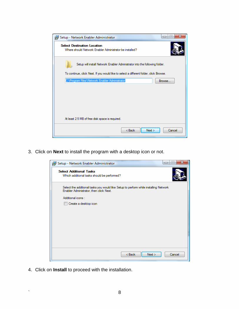
2. Click on Next to install program files in the default directory, or select an alternative
location.
` 8
3. Click on Next to install the program with a desktop icon or not.
4. Click on Install to proceed with the installation.

` 9
5. Click on Next to proceed with the installation.

` 10
Connection There are two ways to connect the FDR unit with your configuration PC. One is to connect the FDR unit with the PC directly with a crossover cable. The other is to connect them to the same network. The configuration steps that follow are the same regardless of the connection method. Configuration To start NPort Administrator, click on StartAll ProgramsNetwork Enabler Administrator Network Enabler Administrator. The Administrator-Configuration window is divided into four parts.
• The top section contains the function list and online help area. (Windows NT does not support this .chm file format.)
• The five Administrator function groups are listed in the left section. • A list of NE-4100T serial device servers, each of which can be selected to
process user requirements, is displayed in the right section. • The activity Log, which displays messages that record the user’s processing
history, is shown in the bottom section.

` 11
The Broadcast Search function is used to locate all NE-4100Ts that are connected to the same LAN as your computer. Since the Broadcast Search function searches by MAC address and not IP address, all NE-4100Ts connected to the LAN will be located, regardless of whether or not they are part of the same subnet as the host. Click on the Broadcast icon to search for the FDR unit.
1. The Broadcast Search window will open and display the Model, IP Address, MAC Address, and Progress of the search for that particular device.
2. When the search is complete, the Broadcast Search window will close, and the NE-4100Ts that were located will be displayed in the right pane of the Administrator window. If you found more than one device connected to this network, refer to the MAC address sticker on your device(s) to determine which device(s) are the ones you wish to configure. To configure an NE-4100T, place the cursor over the row displaying that NE-4100T’s information, and then double-click the left mouse button.
` 12
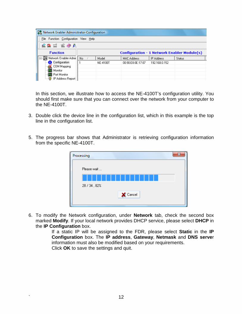
In this section, we illustrate how to access the NE-4100T’s configuration utility. You should first make sure that you can connect over the network from your computer to the NE-4100T.
3. Double click the device line in the configuration list, which in this example is the top
line in the configuration list.
5. The progress bar shows that Administrator is retrieving configuration information
from the specific NE-4100T.
6. To modify the Network configuration, under Network tab, check the second box marked Modify. If your local network provides DHCP service, please select DHCP in the IP Configuration box.
If a static IP will be assigned to the FDR, please select Static in the IP Configuration box. The IP address, Gateway, Netmask and DNS server information must also be modified based on your requirements. Click OK to save the settings and quit.

` 13
7. To modify the serial configuration, under Serial tab, check the box marked Modify, select the first line in the list, and then click the Settings button.
Set all boxes as follows. Click OK to quit.

` 14
8. To modify the Operating Mode, under Operating Mode tab, check the box marked Modify, select the first line in the list, and then click the Settings button.
Select TCP Client Mode in the Operating Mode box. A maximum of four destination IPs can be entered in the Destination Host section.

` 15
ATTENTION Each FDR is assigned an individual port number. Please contact supplier for the port number information before modifying the configuration.
9. Click OK to apply all the changes. Close Network Enabler Administrator. Repower
the FDR unit.

` 16
Troubleshooting
The FNET server continuously monitors each FDR. You can check the status of your unit at http://fnetpublic.utk.edu/tabledisplay.html. If you have received an FDR reset request, it indicates that your FDR is not sending data to the server. In this case, it is helpful to look at the LED indicators on the front of the FDR. Normally, the PPS LED indicator is solid red and will flash every second. If it does not flash, this means that the GPS signal has been lost. Therefore, you should check to see if the antenna has a good view of the sky and also that the antenna cable is securely connected to the GPS ANTENNA port on the back of the FDR. The NET LED indicator is solid green and will flash six times every second. If the LED is off, there is a network problem. Usually, this means that the Ethernet cable has been disconnected from either the unit itself or from the network port. If the LED flashes three times and then remains solid for the following second, it indicates that the network is physically connected, but there is no pathway between the FDR and the FNET server. In this case, you may need to reset the FDR and verify that your Internet connection is working properly. If you continue to experience problems, please e-mail [email protected].

` 17
Frequently Asked Questions
Q. How do FDRs send data to the server? The FDR transmits data as ASCII text “in the clear” (i.e., unencrypted) using TCP. Each FDR is assigned its own TCP port on the server. The server then listens on that port for data from the FDR. Q. What information is contained within the data packet from the FDR? The FDR data packet contains the FDR ID number, GPS time stamp, measured frequency, voltage angle, and voltage magnitude. Please refer to Appendix A for more information. Q. Do I need to change my firewall settings for the FDR? If your firewall allows outbound connections without restriction from within your network, no configuration changes should be required. However, if your firewall restricts connections to certain remote ports, you will need to add an exception for the FDR to allow connections to the server’s IP address and port. Q. Does the FDR support two-way communications? For security reasons, the FDR does not accept incoming TCP/IP connections. Only outbound connections are supported. Q. Why does my FDR unit not send data after installation? Why does the FNET web display show NO DATA for my FDR? There are several typical causes for this error:
1. Internet connection problem. If working normally, the NET LED (green) light on the front panel of the FDR blinks about six times per second without pause. If this light is not lit, it indicates the FDR is not physically connected to the Internet network. In this case, the problem is usually solved by ensuring the Ethernet cable is correctly plugged in. For office hosts, it may also be necessary for the network administrator in your office/company to activate the Ethernet port for use. If the light flashes three times and then remains solid for the following seconds, it indicates the network is physically connected, but there is no pathway between the FDR and the FNET server. If you are sure the Ethernet connection in your location is working correctly for other Internet devices, we strongly recommend contacting your IT support staff or service provider to check the firewall settings.

` 18
Some hosts also reported problems using the FDR with some Netgear routers in DHCP mode. Thus, we recommend using other brands of routers, such as D-Link for connecting the FDR. If a Netgear router must be used, the FDR should be assigned a static IP address. In this case, the FDR will need to be reconfigured accordingly. 2. Loss of GPS. This could last a few seconds to several hours. You can confirm this if the number of locked-on satellites shown on the LCD is “00” (upper right-hand corner). Check the antenna position and make sure the antenna is still connected to the device. 3. Packet loss issues. This is usually very temporary, lasting for only a few seconds at a time. No action is needed. Q. Where does the FDR send data? The FDR can transmit data to a maximum of four destinations. Most existing FDRs send data to servers located at Virginia Tech and the University of Tennessee. However, new FDRs could have other destination IP addresses built-in, if requested by the customer.
Q. Does the FDR have an operating system? The FDR has only an embedded interface provided by the inner Ethernet Moxa device for communication configuration. This interface can be accessed via Telnet console, Web console, or the Network Enabler Administrator software. Typically, the Telnet console and web console are disabled for security reasons. Only LAN access through Network Enabler Administrator software is allowed. Q. Does the FDR use SNMP? No, SNMP (Simple Network Management Protocol) is disabled in your FDR unit. Q. Does the FDR introduce any network security risks? The FDR is shipped with all unnecessary services disabled. We are unaware of any exploits involving the internal serial-to-Ethernet device server that could result in network security risks. Additionally, most FDRs are installed behind NAT (Network Address Translation) firewalls, making them extremely difficult to access from outside the network. Q. My FDR unit is working after installation. Why doesn't my FDR show up on the table display web page? Once the FDR is installed correctly, it can take up to several days (depending on the GPS signal quality of your location) for the GPS receiver inside the FDR to acquire stable GPS signals. Your FDR will be visible on the table display after we’re sure it is working and sending data normally.

` 19
Q. Why does my unit's data appear to be in the wrong order? Data on the public display server has a small random time delay added. This is done to prevent unauthorized "scooping" of the data. Q. Why can’t my FDR unit track the GPS signal inside a room? It may take up to several hours for the FDR to track the GPS signal after the initial installation. If the FDR still cannot acquire the signal after several hours, try to move the antenna to another location with a better view of the sky. Be sure that the antenna is not placed behind low emissivity (“low-e”) glass, since this will filter out the GPS signal. Many newer buildings have low-e glass, while most older ones do not.
Q. Whom should I contact for technical support if I have a problem with the FDR? You can create submit a support request by emailing [email protected]. Please include a brief description of the problem you are experiencing and any steps that you’ve taken to resolve it.

20
Appendix A: FDR Data Packet Description
The FDR transmits data as ASCII text in the clear; i.e., no encryption is used. Frames are fixed-length. Each frame begins with the the byte 0x01 and ends with 0x00. Spaces (0x20) are used to delimit the data. A typical frame would look something like this:
Start Byte UnitID Date Time ConvNum FirstFreq FinalFreq Voltage Angle Stop
Byte Total
Length 1 1 3 1 6 1 6 1 2 1 7 1 7 1 8 1 6 1 55
Hex 01 20 36 39 32 20 30 35 32
31 31 30 20 31 34 32 32 35 35 20 20 33 20 36 30 2E 30
30 34 33 20 36 30 2E 30 30 34 33 20 31 32 30 2E
37 35 37 30 20 32 2E 31 38 36 33 00
ASCII 692 052110 142255 3 60.0043 60.0043 120.7570 2.1863
Notes:
• Each byte is represented in hexadecimal notation. • The date field is in MMDDYY format. In this example, the packet was sent on May 21, 2010. • The time field is in HHMMSS format where 24-hour UTC time is used. The ConvNum field indicates the 0.1 second
interval. In this example, the measurement was made at 14:22:55.3 UTC. • The ConvNum field is left-padded with a space (0x20). • For newer FDRs, the location information is transmitted at the beginning of every minute using the FirstFreq field. The
first sample of the minute will contain the latitude in this field. The second sample will contain the longitude, and the third will contain an integer showing the number of GPS satellites the FDR is using.