frequency controller siga (v6) - afag · the control input makes it possible to have the device...
TRANSCRIPT

Frequency Controller
SIGA (V6)
Translation of operating and installation instructions
Copyright by Afag GmbH

Page 2 7/31/2017 R02.0
This operation instruction applies to:
Typ Bestellnummer
Frequency Controller SIGA (V6) 230 VAC ; 50 Hz / 60 Hz 50195031
Frequency Controller SIGA (V6) 115 VAC ; 50 Hz / 60 Hz on demand
Version of Documentation: BA_SIGA_V6_R02.0_EN.docx
Release: R02.0
Date: 7/31/2017

R02.0 7/31/2017 Page 3
Table of contents:
1 Safety instructions ............................................................................................ 5
Notes on symbols and instructions ........................................................................................................ 5 1.1
Basic safety information ........................................................................................................................ 6 1.2
Specified use .......................................................................................................................................... 6 1.3
2 Description of the device .................................................................................. 7
General .................................................................................................................................................. 7 2.1
Technical Data ....................................................................................................................................... 9 2.2
3 Assembly instructions .................................................................................... 10
Installing the unit ................................................................................................................................. 10 3.1
Connection possibilities ....................................................................................................................... 10 3.2
How to carry out the adjustment ........................................................................................................ 12 3.5
Commissioning..................................................................................................................................... 12 3.6
4 Operating instructions .................................................................................... 13
Conventions ......................................................................................................................................... 13 4.1
Keyboard and Display .......................................................................................................................... 13 4.24.2.1 Addendum .................................................................................................................................. 14
System message after net ON ............................................................................................................. 14 4.3
Display and optimal behavior .............................................................................................................. 15 4.4
Available levels .................................................................................................................................... 15 4.5
Parameter Level 0 (rolling progression of the parameters) ................................................................. 16 4.6
Parameter Level 6 (rolling progression of the parameters) ................................................................. 17 4.7
Parameter Level b (rolling progression of the parameters) ................................................................. 18 4.8
Parameter Level 0 (rolling progression of the parameters) ................................................................. 19 4.9
Truth Table .......................................................................................................................................... 20 4.10
Statusdisplay – Input and Output ........................................................................................................ 21 4.11
5 Options ............................................................................................................. 22
Options for Instrument Settings........................................................................................................... 22 5.1
Amplitude setting ................................................................................................................................ 22 5.2
Frequency Setting ................................................................................................................................ 23 5.3
Setpoint................................................................................................................................................ 24 5.4
Inverting the control signal (herein input E6) ...................................................................................... 25 5.5
Remaining Parameters ........................................................................................................................ 26 5.6
6 Maintenance Instructions ............................................................................... 26

Page 4 7/31/2017 R02.0
Replace the fuse ................................................................................................................................... 26 6.1
Troubleshooting ................................................................................................................................... 26 6.2
7 Address for orders .......................................................................................... 27
8 Disposal ........................................................................................................... 27

R02.0 7/31/2017 Page 5
1 Safety instructions
Notes on symbols and instructions 1.1
Symbols: Assembly and commissioning must be carried out by qualified per-sonnel only and according to these operating instructions.
Please observe the meaning of the following symbols and notes. They are grouped into risk levels and classified according to ISO 3864-2.
DANGER
Indicates an immediate threatening danger.
Non-compliance with this information can result in death or seri-ous personal injuries (invalidity).
WARNING
Indicates a possible dangerous situation.
Non-compliance with this information can result in death or seri-ous personal injuries (invalidity).
CAUTION
Indicates a possibly dangerous situation.
Non-compliance with this information can result in damage to property or light to medium personal injuries.
NOTE
Indicates general notes, useful operator tips and operating rec-ommendations which don’t affect safety and health of the person-nel.

Page 6 7/31/2017 R02.0
Basic safety information 1.2
This description contains the necessary information for the correct application of the product described below. It is intended for use by technically qualified personnel.
Qualified personnel are persons who, because of their training, experience and posi-tion as well as their knowledge of appropriate standards, regulations, health and safety requirements and working conditions, are authorised to be responsible for the safety of the equipment, at all times, whilst carrying out their normal duties and are therefore aware of, and can report, possible hazards (Definition of qualified employ-ees according to IEC 364).
DANGER
Hazardous Voltage! Failure to observe can kill, cause serious in-jury or damage.
Isolate from mains before installation or dismantling work, as well as for fuse changes or post installation modifications.
Observe the prescribed accident prevention and safety rules for the specific application.
Before putting into operation check if the rated voltage for the unit conforms with the local supply voltage.
Emergency stop devices must be provided for all applications. Operation of the emergency stop must inhibit any further uncontrolled operation.
Electrical connections must be covered.
The earth connection must be checked for correct function, after installation.
Specified use 1.3
The units described herein are electrical controllers for installation in industrial plants. They are designed for power adjustment on vibratory feed equipment.
NOTE
Any other use is inappropriate and will result in the warranty be-coming null and void.
See also our General Terms of Business.

R02.0 7/31/2017 Page 7
2 Description of the device
General 2.1
The electronic frequency control device SIGA is used to realize a continuous control of inductive loads like spiral conveyor, linear conveyor and hopper.
The control device works according to the pulse-width modulation (PWM) within the half waves, the period can be adjusted between 20Hz and 99 Hz. The transporting capacity can be diversified by setting the magneto-motive force via the input key-board to a value between 10 - 99%. You can also pro-gram via the keyboard that the nominal value can also be adjusted via an external analogue tension 0-10VDC, ana-logue current 4-20 mA or a potentiometer.
The width of the sinusoidal output voltage (half waves) depends on the period ad-justed and is thus constant. The width of the clocked impulse in this sinusoidal output voltage can be adjusted stepless in the range of the positive resp. negative half wave via keyboard input or via the externally determined nominal value. This adjusts the voltage-time surface of the out-put voltage. For oscillating conveyors the oscillating frequency can be adjusted variably between 20-99Hz, in the standard configuration the adjustment will be made via the keyboard.
When the operating voltage has been switched on the integrated, adjustable smooth start will be made after a forced dead time and guarantees a smoothened run up of the output voltage up to the adjusted voltage level. Via a limiter stage at the switch-on moment the charging current is limited to capacities of 4A. This eliminates possi-ble switch-on peaks. Also the smooth start as well as the smooth run-out will become effective via the control input or the keyboard when the output voltage is switched on or off. In this way the transporting capacity can be increased or decreased in a time-dependent way. So bulk material that has already been positioned will not lose its position. Both time values can be adjusted separately.
The control input makes it possible to have the device switched on or off by another system (SPS, approach switch, sensor etc.)
The control device provides its own supply voltage of +24 V DC for this purpose. It is also possible to switch the device on or off via external voltage of + 24 VDC. This in-put internally influences the PWM.
The control input control the runtime of the oscillating conveyor in a way that avoid unnecessary runtimes.
You can determine via the keyboard whether the device is to work in the opener mode or in the closer mode.
NOTE
Miniature magnets can also be operated safely at the IRG 1-S con-troller!

Page 8 7/31/2017 R02.0
CAUTION
In the case of applications that require the oscillation conveyor to be switched ON and OFF constantly (e.g. dust switching, hopper control system, etc.), the prescribed controller input must be used. If the load circuit is disconnected with a switch or a relay the controller may be damaged.
If the controller is switched on, never insert or remove the plug at the vibration conveyor being operated. This can damage the ap-pliance.
NOTE
Repairs may only be carried out by qualified technicians. We rec-ommend that all repairs are carried out by the manufacturer
WARNING
Procedure by the high-voltage test.
- L and N have to be together related.
- Test voltage must not higher be as 1000V AC.
- Each controller must be individual checked.
At noncompliance above mentioned criteria can take the frequency-control-device of damage and goes out the guarantee!

R02.0 7/31/2017 Page 9
Technical Data 2.2
Figure 1: SIGA
80
12
3 4
200
100
Lochabstand 87mm
Loch
ab
sta
nd 1
87m
m
Lochdurchmesser 4 x 5mm für Schraube M4WERTVALUE
MENÜ
MENUE
EBENE
LEVEL
Prog.
membrane keyboard flange type socket
socket M12 x 1 control input M12x1,5-blind plug
power supply
M12x1,5-blind plug
Table 1: Technical Data
Type Unit SIGA B.7/65.1 (V6)
Operating voltage [VAC] 230 / ±10% (115 / +10%)
Operating frequency [Hz] 50 / 60
Output voltage [VAC] 50 – 250
Output current [A] 0,025 – 5
Degree of Protection --- IP54
Fuses --- 2 x 6,3 A (F)
Anschlussart Netz --- 2m cable with integral earthing pin plug
Anschlussart Schwingförderer --- Contact socket EMV – HA3-BS
Anschluss Steuereingang --- M12x1 ; 4-pin
Abmessungen (l x b x h) ca. [mm] 200 x 100 x 80 Ambient temperature [°C] 0…50°C

Page 10 7/31/2017 R02.0
3 Assembly instructions
Installing the unit 3.1
There are four holes on the underside for mounting the controller. The holes are sep-arated from the interior of the housing.
- Unscrew the cover fastening screws. - Remove the cover. - Insert the fastening screws into the channels and use them to attach the con-
troller to a vibration-free base. - The drive cable has to be shielded
Connection possibilities 3.2
NOTE
The connection between control device and oscillating conveying unit must be realized with a shielded cable!

R02.0 7/31/2017 Page 11
Figure 2: Connection possibilities
L N
vibration-unit
MN
grounding
load-connection
L1 N 1 2
mains plug
control inputfor externalsensor NC-NOor SPS
ML
power-supply
E
Control input
7 8 9
GN
D
+2
4V
DC
GN
D
control board load board
programming pinswithout function
1
1
L N PE PE PE PE MN ML
power supply load connection
SI = 6,3AF
SI = 6,3AF
7 8 9
15
26
externalpotentio-meter
externalvoltage-source0 - 10V DC
externalcurrent-source4- 20 mA
10 kOhm
E
1 5 2 6
+5
VD
C
1 5 2 6
GN
D U
1 5 2 6
GN
D
PE - Earth1 - Load2 - Load3 - NotCon
1
2
PE
3
12
3 4
1 - NotCon2 - NotCon3 - KL 74 - KL 8
CAUTION
Jumpers may only be inserted for the respective application, oth-erwise this may lead to a malfunction of or damage to the p.c.b.
Page 12 7/31/2017 R02.0
How to carry out the adjustment 3.5
At the oscillating conveying unit you will have to determine the mechanical resonant frequency using the SIGA. For this purpose the oscillating convey-or will only be loaded with a test part. Then you use SIGA to slowly run the drive frequency. When there is a mechanical resonance the test part is at its maximum velocity. (Attention! Two or more resonance positions are possible).
The main resonance position is the one showing the highest part velocity. But in this condition the system is very soft (the transporting velocity depends on absorbing). The output frequency at SIGA must be adjusted approx. 1,5Hz higher than the me-chanical resonant frequency (forced oscillation). This makes the transporting system mechanically stable and keeps the trans-porting velocity constant, also with changing weights. The final adjustment of the transporting capacity will then be made via the nominal value (oscillating force).
This concept does not only result in a multiplication of the efficiency by current re-generation but also in a high stability of the transporting velocity and tremendously facilitates the mechanical adjustment works. The output frequency of SIGA is abso-lutely stable.
Commissioning 3.6
- Before connecting the control device SIGA the el. data of the oscillating con-
veyor to be operated are to be determined and to be compared with the tech-nical data of the control device. The output current of 5A must not be exceed-ed.
- Connect the oscillating conveyor to the control device. The connection be-tween control device and oscillating conveying unit must be realized with a shielded cable !
- Connect the mains plug into the control device. - Switch on control device. - Adjust via the keyboard the operating frequency of the oscillating conveyor
according to adjustment specification

R02.0 7/31/2017 Page 13
4 Operating instructions
- Before switching on, check that the controller has been correctly connected to the oscillation conveyor.
- Switch the frequency controller on with a mains switch. - If required, set the setpoint value until the vibration conveyor achieves the re-
quired output.
Conventions 4.1
The Documentation describes how you can do the feeding also with the keyboard. This Documentation uses the following conventions:
Tabelle 2: Conventions
Convention Meaning
LO defines the logical level for the controller at the inputs.
The condition 0 is with it fixed
HI defined the logical level for the controller at the inputs.
The condition 1 is with it fixed
Keyboard and Display 4.2
Figure 3: Keyboard and Display

Page 14 7/31/2017 R02.0
4.2.1 Addendum
Table 3: Addendum
Symbol Meaning
button to program, i.e. to change the value of a parameter the sys-tem must be changed into programming mode. By pushing this button one time, the system is prompted to allow changes. Some areas of the parameters are protected with a CODE and require further input.
Button to save, i.e. after changing the values of parameters and wishing to permanently save this new values (also after net ON/OFF) the button has to be pressed once. . After pushing this button the word SAVE briefly appears in the display for confirmation and disappears again.
The operation and setting of the device is controlled with 8 keys that are located to-gether with an LED display in a control panel on the front panel. All parameter settings can be made through this panel. By using the value keys by briefly pressing the display of one digit (or tenths or letter) is increased / decreased / changed. Keeping the keys pressed, the system switches to continuous operation and after 3 seconds in fast mode,
ie automatically increase / decrease the values / change at different speeds.. It means that the values are automatically updated, reduced, modified with different speed.
To avoid some Accidental Release or unauthorized change, the machine settings are locked via a CODE until the amplitude.
Changed data are not automatically stored. The Settings get cleared after 20 se-conds if there are no button movement.
If you change some data you must save it with this button.
System message after net ON 4.3
As soon as that frequency-control-device switched on to the supply voltage and over the power switch, the apparat reports after an initialization phase ready to operate.
For Example following messages are indicated on the 6-parts display:
System SIGA
Day, month and year of the compiling

R02.0 7/31/2017 Page 15
Display and optimal behavior 4.4
All points of the 6-part Display are defined for a special function.
Tabelle 4: Display und Bedienverhalten
Stelle Display Bedienverhalten
1
The first place shows the level (attached parameterblock to physical in- and out-puts) where the parameters are configur-ated.
2; 3
The second and the third Place show the setting parameters.
4; 5; 6
Place four, five and six show the setting account.
Punkt
Exception: Point for programming mode.
Available levels 4.5
Table 5: Available levels
Level Display Meaning
0
Level 0 contains all adjustable parame-ters for the vibratory drive.
A ; F ; SA ; SS ; AE ; F0 ; d
6
Level 6 contains all adjustable parame-ters for a sensor / PLC
F1
b
Level b contains all adjustable parame-ters for the status of the vibratory drive that is used as input.
F1 ; S1 ; S2
0
Level 0 contains all adjustable parame-ters for the definition of the logical de-pendence of the vibratory drive on the controlling inputs.
L ; E6 ; Eb

Page 16 7/31/2017 R02.0
Parameter Level 0 (rolling progression of the parameters) 4.6
Table 6: Parameter Level 0
Parameter Display Erklärung
A
A parameter defines the amplitude (out-put voltage) as a percentage. The ampli-tude moves in their value between 10 and 99 in 1s increments. 10 is the minimal set output voltage. 99 is the maximum output voltage set.
F
Parameter F defines the oscillation fre-quency of the vibratory drive. The value is adjustable between 20.0 and 99.9 in 0.1s increments, i.e. at 20.0 2400 oscillations / min and at 99.9 11988 oscillations / min are generated. (Mains frequency inde-pendent)
SA
Parameter SA defines the set soft-start ramp of the vibratory drive. The value is between 0.1 and 2.9 seconds. The step size is 0.1 seconds. The output voltage runs after activation of the vibratory drive from 0V AC linearly to the set amplitude value within the set time SA.
SS
Parameter SS defines the set soft stop ramp of the vibratory drive. The value is between 0.1 and 2.9 seconds. The step size is 0.1 seconds. The output voltage runs after deactivation of the vibratory drive from the set amplitude value linearly to 0 V AC within the set time SS.
AE
AE parameter defines the setpoint for the system. The value can be set to P, U, I, F. P defines setpoint via an external po-tentiometer-meter (recommended 10K linear) U defines setpoint via external voltage 0 - 10 V DC I defines setpoint via external power 4 - 20 mA DC F defines setpoint its own keypad Note: If no external connection require-ments be technically available, the sys-tem will stop responding, external input should be programmed and set.

R02.0 7/31/2017 Page 17
F0
Parameter F0 defines the mode in which the vibratory drive to work. The value can be set to G and H. G is full-wave mode (electric oscillation - flow above and be-low the zero line) H half-wave operation means (electric oscillation - Power on on-ly one side of the zero line, the other side will be hidden)
d
Parameter d defines the mode in which the vibratory drive to work. The value can be set to 0.1 and E. 0 means vibratory drive runs continuously. 1 means vibratory drive is permanent. E is vibratory drive is running or is a function of the control targets (active programmed logic). The closer the value is the programmed setpoint, the smaller the deviation.
Parameter Level 6 (rolling progression of the parameters) 4.7
Tabelle 7: Parameter Level 6
Parameter Display Meaning
F1
Parameter F1 defines a logic gate having a valence of S or O. The present at the input logic signal is processed according to the set value as follows (that signal is inverted or non-inverted):
O set:
- Logical HI stays HI (not inverted).
- Logical LO stays LO (not inverted).
S set: - Logical HI will be LO (inverted).
- Logical LO will be HI (inverted).

Page 18 7/31/2017 R02.0
Parameter Level b (rolling progression of the parameters) 4.8
Table 8: Parameter Level b
Parameter Display Meaning
F1
Parameter F1 defines a logical element having a valence of S or O. The present at the input logic signal (logic LO when the swing drive is running, logical HI when the vibratory drive is) is processed according to the set value as follows (that signal is inverted or not inverted):
O set:
- Logical HI stays HI (not inverted).
- Logical LO stays LO (not inverted).
S set: - Logical HI will be LO (inverted).
- Logical LO will be HI (inverted).
S1
Parameter S1 has the value 0.0 to 9.9 seconds with an increment of 0.1 se-conds, and defines the delay of the asso-ciated input set as follows: Alternating logic level of LO to HI by F1 not inverted passes after a set time the logic level HI of logic control, if the logic level does not change again at the en-trance. For each logic change times to be restarted. Alternating logic level of LO to HI inverted by F1 passes after a set time the logic level at LO logic control, if the logic level does not change again at the entrance. For each logic change times to be restarted.
- Drop delay is programmed as if F1 is set O
- Tightening delay is programmed as if F1 is set S
S2
Parameter S2 has the value 0.0 to 9.9 seconds with an increment of 0.1 se-conds, and defines the delay of the asso-ciated input set as follows: Alternating logic level from HI to LO by F1 not inverted passes after a set time the logic level at LO logic control, unless the local level does not change again at the entrance. For each logic change times are restarted. Alternating logic level from HI to LO by F1

R02.0 7/31/2017 Page 19
not inverted passes after a set time the logic level at LO logic control, if the logic level does not change again at the en-trance. For each logic change times are restarted.
- Tightening delay is programmed as if F1 is set O
- Drop delay is programmed as if F1 is set S
Parameter Level 0 (rolling progression of the parameters) 4.9
Table 9: Parameter Level 0
Parameter Display Erklärung
L
Parameter L specifies the logical opera-tion of the selected inputs based on the vibratory drive. As a shortcut AND (U), OR (O) and JAM (S) can be selected. There are all inputs are available offering software programmable. The inputs that are active links must be identified by se-lection with 1. The inputs that are to be disregarded must be identified by selec-tion with 0. The truth table of the shortcuts for 2 in-puts are at the end of the parameter de-scription.
LE6
LE6 parameters, the possibility of selec-tion. 0 -> input signal E6 is not included in the logic function 1 -> input signal E6 is included in the logic link.
LEb
Parameter LEb (status of the vobratory drive) provides the possibility of selec-tion. 0 -> input signal Eb is not included in the logic link 1 -> input signal E6 is included in the logic link

Page 20 7/31/2017 R02.0
Truth Table 4.10
Table 10: Example: Truth table for AND – connection and F1 = 0 for E6 and Eb
Input E6 LO HI LO HI
Input Eb LO LO HI HI
Output A0 runs runs runs off
Table 11: Example: Truth table for AND – Connection and F1 = S for E6 and Eb
(F1 inverted the Input Signals)
Input E6 LO HI LO HI
Input Eb LO LO HI HI
Output A0 off runs runs runs
Table 12: Example: Truth table for OR – Connections and F1 = 0 for E6 and Eb
Input E6 LO HI LO HI
Input Eb LO LO HI HI
Output A0 runs off off off
Table 13: Example: Truth table for OR – Connection and F1 = S for E6 and Eb
(F1 inverted the Input Signals)
Input E6 LO HI LO HI
Input Eb LO LO HI HI
Output A0 Off off off runs
Table 14: Example: Truth table for PACK-Up – Connection and F1 = 0 for E6 and Eb
Input E6 LO HI LO HI LO HI LO HI
Input Eb LO LO HI HI LO LO HI HI
Indicator LO LO LO LO HI HI HI HI
Output A0 runs runs runs off runs off off off
Table 15: Example: Truth Table for PACK-Up – Connection and F1 = S for E6 and Eb
(F1 inverted the Input Signals)
Input E6 LO HI LO HI LO HI LO HI
Input Eb LO LO HI HI LO LO HI HI
Indicator LO LO LO LO HI HI HI HI
Output A0 off runs runs runs off off off runs
The Indicator must be on HI, when two Inputs are on HI, then reverse to LO if both Inputs become LO.
R02.0 7/31/2017 Page 21
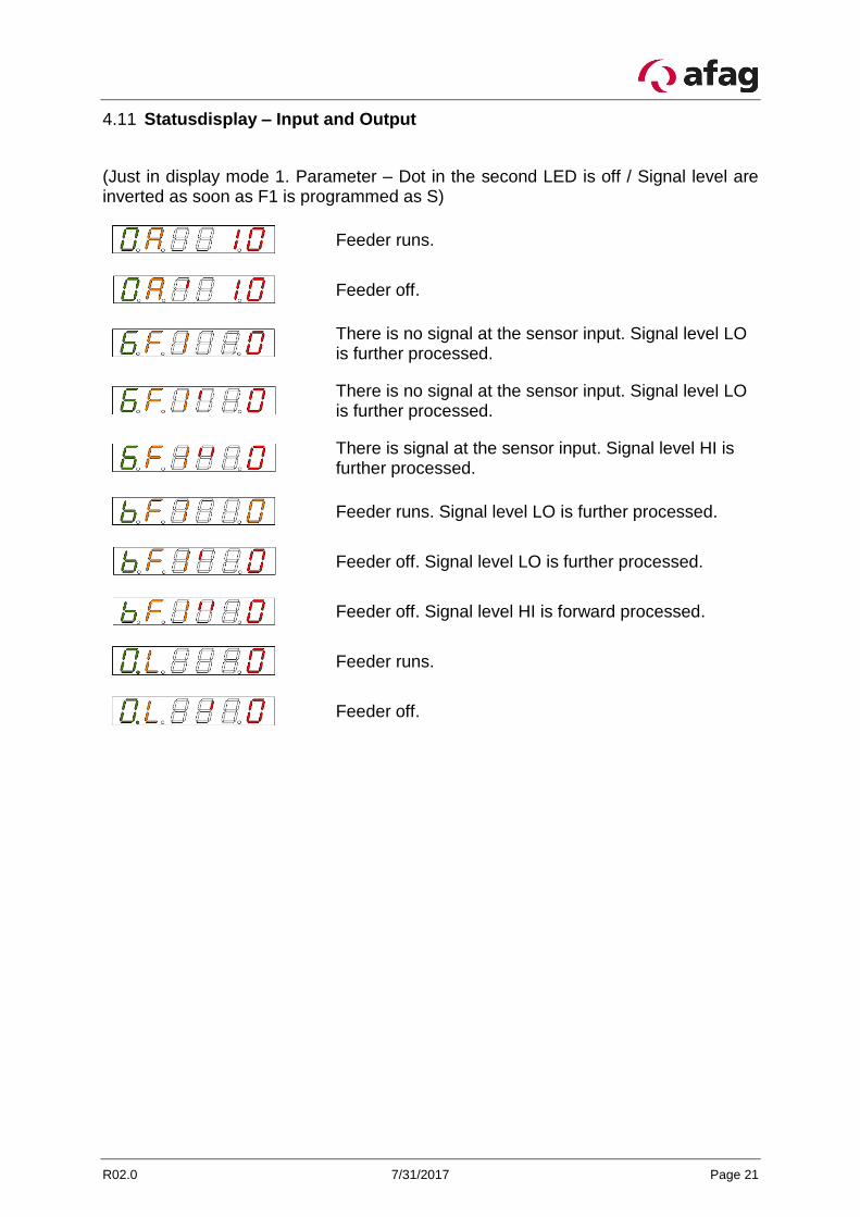
Statusdisplay – Input and Output 4.11
(Just in display mode 1. Parameter – Dot in the second LED is off / Signal level are inverted as soon as F1 is programmed as S)
Feeder runs.
Feeder off.
There is no signal at the sensor input. Signal level LO is further processed.
There is no signal at the sensor input. Signal level LO is further processed.
There is signal at the sensor input. Signal level HI is further processed.
Feeder runs. Signal level LO is further processed.
Feeder off. Signal level LO is further processed.
Feeder off. Signal level HI is forward processed.
Feeder runs.
Feeder off.

Page 22 7/31/2017 R02.0
5 Options
Options for Instrument Settings 5.1
Table 16: Options for Instrument Settings
Parameter Area / Values Factory Setting
Feeder
Oscillation amplitude (Feeder capability)
(A) 10 – 99% 10%
Swingfrequency (F) 20.0 – 99.9 Hz 50.0 Hz
Acceleration ramp soft start (SA) 0.1 – 2.9 Sek. 2.9 Sek.
Acceleration ramp soft stop (SS) 0.1 – 2.9 Sek. 2.9 Sek.
Shift on extern given value (AE) U / I / P / F F
Given Value 4 – 20 mA DC I
Given Value 0 – 10 V DC U
Given Value Potentiometer 10K P
Full – Half shaft driven (F0) G / H G
Control (d) 0 / 1 / E E
Sensor
Input inverted (F1) O / S O
Status Vibratory Feeder
Input inverted (F1) O / S O
Duplicate timing relay (S1/S2) 0.0 – 9.9 Sek. 0.1 Sek. / 0.1 Sek.
Logic Vibration Conveyor
Logic (L) U / O / S O
Inputs (E6) 0 / 1 1
Inputs (Eb) 0 / 1 0
Amplitude setting 5.2
Origin Display
Push the button.
Point in the second LED appears. Programming mode active. The amplitude can be changed.
Use the value keys to set the value.
For example at 75.
Push the button.
It appears briefly that the changes were stored.

R02.0 7/31/2017 Page 23
After 20 seconds without pressing a button, the programming mode is exited and the origin is displayed without a point.
Frequency Setting 5.3
Origin Display.
Push the button.
Parameter Frequency programmed at 50.0 Hz is dis-played.
Push the button.
Code input is expected.
Push the button.
Push the button.
Push the button.
Push the button.
Dot appears in second LED. Programm mode is active. The amplitude can be changed.
The value can be changed by the value keys.
For example at 55.8 Hz.
Push the button.
It appears briefly, that the changes were saved.
After 20 seconds without pressing a button, the programming mode is exited and the origin is displayed without a point.
Page 24 7/31/2017 R02.0
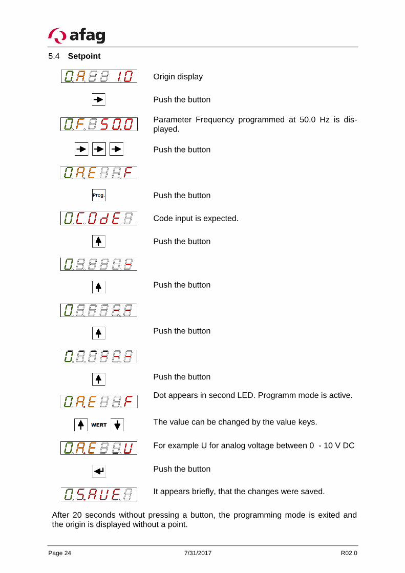
Setpoint 5.4
Origin display
Push the button
Parameter Frequency programmed at 50.0 Hz is dis-played.
Push the button
Push the button
Code input is expected.
Push the button
Push the button
Push the button
Push the button
Dot appears in second LED. Programm mode is active.
The value can be changed by the value keys.
For example U for analog voltage between 0 - 10 V DC
Push the button
It appears briefly, that the changes were saved.
After 20 seconds without pressing a button, the programming mode is exited and the origin is displayed without a point.

R02.0 7/31/2017 Page 25
Inverting the control signal (herein input E6) 5.5
Origin display.
Push the button.
Push the button.
Code input is expected
Push the button.
Push the button.
Push the button.
Push the button.
Dot appears in second LED. Program mode is active.
The value can be changed by the value keys.
The Control signal is converted to NO. LO signal at the input E6 is further processed as HI signal.
Push the button.
It appears briefly, that the changes were saved.
After 20 seconds without pressing a button, the programming mode is exited and the origin is displayed without a point.

Page 26 7/31/2017 R02.0
Remaining Parameters 5.6
All other parameters are available to be programmed in the same way:
- Approaching the parameter point - Activate programming mode CODE - Change the value - Save
6 Maintenance Instructions
Replace the fuse 6.1
Procedure:
1. Always disconnect the mains plug before opening the control unit.
2. Loosen the cover screw.
3. Replace defective fuse.
4. Close the housing again.
Troubleshooting 6.2
Tabelle 17: Troubleshooting
Disorder: Repairing:
Device is not working Check the mains voltage, if necessary, check or replace fuses.
Check the control signals
Conveyor has no performance Chekc if the correct resonant frequency iss et, if neccessary, change the settings.
Conveyor vibrates too much, mag-net knocking (noises)
Incorrect setting of the oscillation frequency or amplitude. CAUTION! Magnet can be de-stroyed by overheating or mechanical damage to the magnets by hitting operating.
Setting of the setpoint is too high.
Magnet is hot Incorrect oscillation frequency set, change if necessary.
Control input is not working Control voltage with reversed polarity, check.
R02.0 7/31/2017 Page 27
7 Address for orders
Germany:
Afag GmbH
Wernher-von-Braun-Straße 1
D – 92224 Amberg
Tel.: ++49 (0) 96 21 / 65 0 27-0
Fax: ++49 (0) 96 21 / 65 0 27-490
Sales
www.afag.com
Switzerland:
Afag Automation AG
Zuführtechnik
Fiechtenstrasse32
CH – 4950 Huttwil
Tel.: ++41 (0) 62 / 959 86 86
Fax: ++41 (0) 62 / 959 87 87
8 Disposal
Controllers that are no longer in use should not be disposed of as complete units but dismantled into separate materials and recycled. Non-recyclable components must be disposed of correctly.