frenic - aquamedia.bizwebmedia.net/sites/88810/upload/documents/frenic_aqua... · the frenic-aqua...
TRANSCRIPT

MEH601
Smile to the Environment
AQUAHigh performance enabled by the comprehensive use of Fuji technology.
Easy maintenance for the end-user.Maintains safety and protects the
environment.Opens up possibilities for the new generation.

FRENIC-AQUASmile to the Environment
~ Energy Saving for the environment and our children's future ~
2
The first slim-type inverter specialized in energy-saving from Fuji Electric.Achieves a great effect on power-saving of pumps and blowers!Contributes drastically to cost reduction by cutting power consumption!
The first slim-type inverter specialized in energy-saving from Fuji Electric.Achieves a great effect on power-saving of pumps and blowers!Contributes drastically to cost reduction by cutting power consumption!The water business market including water purification plants and wastewater plants has continued to grow in recent years. Using a large volume of water, cost reduction is required and it largely depends on how efficiently water can be managed. It is of course achieved by reducing the amount of water to be used, however, the reduction in power consumption in water transfer and supply also allows significant cost reduction. And the key to that is the dedicated inverter which controls pumps and motors. The FRENIC-AQUA series, a Fuji’s new product, helps energy-saving of pumps, eliminating ineffectual operations by adjusting the amount of water properly to produce a significant effect both on electricity conservation and on cost reduction.
3
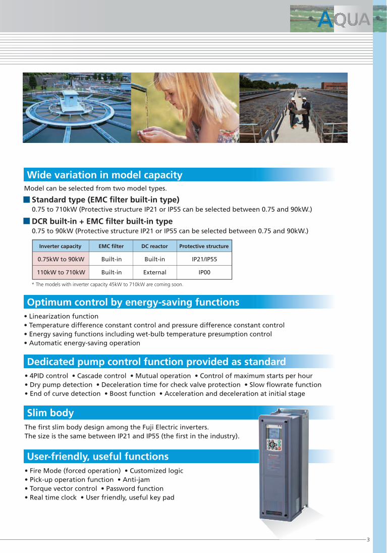
Wide variation in model capacity
Optimum control by energy-saving functions
Slim body
Model can be selected from two model types.
Standard type (EMC filter built-in type)
0.75 to 710kW (Protective structure IP21 or IP55 can be selected between 0.75 and 90kW.)
• Linearization function
• Temperature difference constant control and pressure difference constant control
• Energy saving functions including wet-bulb temperature presumption control
• Automatic energy-saving operation
Dedicated pump control function provided as standard
• 4PID control • Cascade control • Mutual operation • Control of maximum starts per hour
• Dry pump detection • Deceleration time for check valve protection • Slow flowrate function
• End of curve detection • Boost function • Acceleration and deceleration at initial stage
• Fire Mode (forced operation) • Customized logic
• Pick-up operation function • Anti-jam
• Torque vector control • Password function
• Real time clock • User friendly, useful key pad
The first slim body design among the Fuji Electric inverters.
The size is the same between IP21 and IP55 (the first in the industry).
User-friendly, useful functions
DCR built-in + EMC filter built-in type
0.75 to 90kW (Protective structure IP21 or IP55 can be selected between 0.75 and 90kW.)
0.75kW to 90kW
110kW to 710kW
Built-in
Built-in
Built-in
External
IP21/IP55
IP00
Inverter capacity EMC filter DC reactor Protective structure
* The models with inverter capacity 45kW to 710kW are coming soon.

4
• Water purification plant and wastewater, clean water and sewage treatment plants
Wide Usage for Water Treatment
Fuji Electric offers high-reliable inverters based on broad ideas focusing on future and with pinpoint
technical support while meeting the complicated needs regarding water treatment that requires stable
water supply and effective use of resources.
FRENIC-AQUA features dedicated functions as standard that are required in water treatment plants, such
as 4PID control, cascade control, dry pump detection, slow flowrate function, and pick-up operation, as
well as many options. These functions contribute strongly to protection of system and reduction of cost.
The pumps and blowers used in water purification, water supply and wastewater treatment plants need
to be controlled with accurate pressure (discharge pressure). FRENIC-AQUA realizes optimal process
control with high-integrity using the built-in PID controller.
The cascade control can control up to eight units + one unit (auxiliary motor), allowing for application
to the large-scale system. In addition, since the operation time of each pump and blower is equalized in
cascade control, the system life can be prolonged.
• Irrigation system
• Seawater desalination

5
FRENIC -AQUA series is equipped with many functions that control the pumps and blowers used in water
treatment facility optimally.
• Pump
• Blower
• Fluid-pressure device
Characteristics in pump usage Advantages
Cost reduction
Longer service life of the system
Process optimization
Cost cutting
Pump protection
Energy saving
Initial cost cutting
No heater required
Cascade control
(Max. 8 units + 1 unit [auxiliary motor])
(Homogenization of operation hour)
Built-in PID controller
Dry pump detection
Mutual operation
Condensation prevention function
Characteristics in blower usage Advantages
Process optimization
Cost cutting
Energy saving
No heater required
Blower protection
Built-in PID controller
Automatic energy-saving operation
(Energy-saving operation according to load)
Condensation prevention function
Pick-up operation
• Oil pumping system
• Injection machine
• Hydraulic press machine
• Extruders

6
User friendly, easy to see keypad
1. Present value (PV)
2. Setting value (SV)
3. Manipulating value (MV)
4. Frequency
• Possible to set the maximum four timers for a week.• Possible to set flag holidays (20 days a year).
• Alarm information for last ten times is stored and displayed with date and time.
• Unit conversion allows you to easily set data.
• Alarm information with date and time
• Unit conversion function between PV and SV values
• Timer function
* Languages in parentheses are soon to be supported.
Real time clock (RTC) is provided as standard.
Japanese
Spanish
(Malay)
(Czech)
English
Italian
(Vietnamese)
(Swedish)
(Chinese)
(Russian)
(Thai)
(Portuguese)
German
(Greek)
(Indonesian)
(Dutch)
French
(Turkish)
(Polish)
Language
When operation is performed in the
same schedule through a week
When operation schedule varies depending
on the day of the week
24:00:00
18:00:00
12:00:00
06:00:00
00:00:00
Example
Easy failure
analysis
Operation schedule can be set according
to actual condition by using four timers.
• The regulator is indicated by enlarging the LCD.
Optimal Structure Design
*Possible to show understandable indications through the unit conversion function.
*Multi-language function: 19 languages + user customized language supported
5. Output current
6. Output voltage
7. Torque
8. Rotation speed
9. Power consumption
10. Cumulative energy
• Multi-language supported: 19 languages + user customized language
No conversionm3/h
kPa
in-wg
PSI
%
˚C
mWG
psi
RPM
mbar
mmHg
˚F
l/min
bar
kW
ppm
Unit conversion
Function Units
24:00:00
18:00:00
12:00:00
06:00:00
00:00:00MON TUE WED THU FRI SAT SUN MON TUE WED THU FRI SAT SUN

7
Multi-language supported, HELP function featured, unit
setting with SV and PV values, data copy (three kinds),
detachable and can be attached on the panel (using an
optional cable)
Outputs the life prediction signal
determining capacitor capacity
drop and cumulative running
hours. This allows the user to grasp
replacement period.
USB port equipped, BACnet equipped as standard.
Max. three types of built-in optional boards can be mounted all together.
Optional battery connection
Various communications options
Control board
The detachable control terminal
block is adopted. This allows the unit
to be replaced easily without
disconnecting cables.
Control terminal block
Drastically reduces harmonic noise. Conforming to
IEC/EN61000-3-2 and IEC/EN61000-3-12. Provided
as standard (to models up to 90kW), and can be
attached externally as an option (to models from
110kW to 710kW).
Capacitor board
Drastically reduces noise.
Provided to units of all
capacities. Conforming
to IEC61800-3.
EMC filter
Easy replacement just by
simply removing and
attaching the part. Life
prolongation is possible by
controlling ON and OFF.
Cooling fan
3C2, IEC60721-3-3 supported
Support/analysis software by loader, RTC backup by
battery (option)
DCR
Environmental immunity
Others
Standard equipment Optional equipment
• BACnet MS/TP
• Modbus RTU
• Metasys N2
• LonWorks
• Ethernet
• Profi bus
• DeviceNet
• CANopen
• CC-Link
User-friendly, easy to see dedicated keypad

8
The system is configured by combining the motor driven by the inverter (M0), motors that are commercially driven (M1 to M8) and auxiliary motor (MA). The motor driven by the inverter is always fixed as motor M0. Motors commercially driven are added one by one in control when the required discharge flow rate cannot be achieved with the motor M0 only.
1. Inverter drive motor fixed method (FIXED)
The cascade control is the function that controls the multiple pumps by one inverter. The pumps are controlled with combination of inverter drive and commercial drive. This can be applied in a large-scale water treatment plant.In cascade control, the signals of flow rate and pressure sensors are controlled by the PID regulator that is built in the inverter. Each pump is driven either by the inverter or commercially according to the switching signal from the inverter. The pumps are controlled only by the inverter when the discharge volume is small, and adding to the inverter drive, they are controlled using commercial drive by adding them one by one as the discharge volume gets larger in order to ensure the required discharge volume in total. There are two following methods in control: inverter drive motor fixed method and inverter drive motor fixed method.
Optimal Function for Usage in Water Treatment
Cascade control
Pressuresensor
Contactor box
FRENIC-AQUA
Pump
Pump
Pump
Pump
Pump
Pump
Pump
Pump
Pump
Auxiliarypump
Com
man
d
Control
unit for
pump
Pressure sensor
PID
HLRINVRST
UVW
M1_LM2_L
M3_LM4_L
M5_LM6_L
M7_L
AUX_LM8_L
M0
M1
M2
M3
M4
M5
M6
M7
M8
MA
Inverter drive motor fixed method (FIXED)
Max. 1 unit
(Driven by inverter)
8 units
(Commercially driven)
1 unit
(Auxiliary motor)

9
The system for this method is configured by combining the motors that can be switched between inverter drive and commercial drive (M1 to M4) and auxiliary motor that are commercially driven (MA). The motors are driven by the inverter with variable speed control at start. When the desired discharge flow rate cannot be achieved with the first motor, operations FLOATING-1 or FLOATING-2 can be selected.
2. Inverter drive motor floating method (FLOATING)
Optimal Function for Usage in Water Treatment
Inverter drive motor floating method (FLOATING)
Max. 4 units 1 unit (Auxiliary motor)
Controlunit forpump
PID
HLRINVRST
UVW
M1_IM1_LM2_IM2_LM3_IM3_LM4_IM4_L
AUX_L
Pump
Pump
Pump
Pump
Auxiliarypump
Pressure sensor
M1
M2
M3
M4
MA
The system can be configured without using a controller by connecting the inverters via communications. In this system, if a failure occurs to the master inverter, the next inverter is driven as the master inverter. Moreover, wiring can be saved with use of communications services, which eliminates the need of additional options by using the Modbus RTU communications.
Mutual operation
The first motor: Inverter drive continued
Second and subsequent motors: Commercially driven
FLOATING-1
FLOATING-2
The first motor:Switched as a commercially driven motor
Second and subsequent motors: Operated by inverter driveThe inverter-driven motor is changed by rotation as the motor is added.
Command
PID control
PIDcontrol
Accel/decelcontrol
Pressure sensor
Pump
Feedback
L1/RL2/SL3/T
UVW
Command PIDcontrol
Accel/decelcontrol
Pressure sensor
Pump
Feedback
L1/RL2/SL3/T
UVW
Command PIDcontrol
Accel/decelcontrol
Pressure sensor
Pump
Feedback
L1/RL2/SL3/T
UVW
M0
M0
M0
Command

+
-
10
Frequency can be output forcibly at a fixed rate in preference to PID control. By setting the operation frequency, operation time, and acceleration time at starting, optimal operation for starting the pump can be achieved.
• Pressurizing operation can be applied for a certain period of time at the time of start.
Function codes can be read/write, displayed or hidden by setting the two passwords. This prevents erroneous operation or overwriting of function codes. In addition, if a wrong password was input exceeding the specified number of times, the inverter is restricted from operating as the user is regarded as improper.
Password
Pump dry condition can be detected from PID deviation value by setting the output frequency, output current, and flow rate sensor value. Water leakage and pressure drop due to impeller damage can be detected as well.
Dry pump detection
The customized logic interface function is provided to the inverter body. This enables forming of logic circuit and arithmetic circuit to the digital and analog input and output signals, allowing simple relay sequence to be built while processing the signals freely.
Customized logic
Boost function
X1 terminal 12 terminal
C1 terminal
U04
U04
U05
LE1LE2
On-delay timer
Step 1
X2 terminalY1 outputterminal
Y3 outputterminal
Example
0.2
Pressure
[FDT]
Time
Operation frequency
Operation time
0

11
The inverter can be stopped when the discharge rate becomes low due to increase of pump discharge pressure. Facility having a bladder tank can make the stoppage period longer by applying pressure immediately before stoppage, which realizes energy-saving operation.
Slow flowrate function (pressurized operation available before slow flowrate)
Frequency level for slow flowrate function
Output current
Elapse time before stop with slow flowrate
Pressurization time before stop with slow flowrate
Pressurization frequency before stop with slow flowrate
The motor is rotated in reverse when it is determined that any abnormality, such as being engaged or trapped, is occurred. If sand or dust were caught in the impeller with a submerged pump and overcurrent protection function is activated, the motor is rotated in reverse at restart so that the sand and dust are ejected from the impeller. Then, the motor resumes rotation in forward, allowing water to be supplied in a normal manner.
Anti-jam function
If a valve is closed quickly after pump stoppage, there is a risk of damaging the check valve (piping, pump, valves, etc.) due to water hammer phenomenon. To protect the check valve from this, the pump speed is gradually slowed down when the check valve closes.
Deceleration time for check valve protection
When a pump such as a deep well pump is operated at low speed over a long period of time, the pump may be damaged since the load current is large in the low-speed range. It is possible to provide acceleration/deceleration time specific to the low-speed range in order to avoid prolonged operation.
Initial acceleration/deceleration time
Output frequency
Starting frequency
Startup frequency
PID output (MV)
Operation instruction
Signal during slow flowrate function[PID-STP]
ON
ON
Timert
t
Low frequency domain
Output frequency
Output frequency
Output frequency
Minimum frequency
Lower limiter
Switching frequency
PID control: PID-CTL ON
Initial acceleration time
Initial deceleration ime
Deceleration time for check valve protection
Check valveprotection frequency
Slow flowrate function
Slow flowrate function
Start
Other featured functions
• 4PID control • Control of maximum starts per hour• Abnormal pressure rise prevention • End of curve detection• Pick-up operation

12
3-phase, 400V series (0.75 to 37kW)
Rated capacity [kVA] *2
Voltage [V] *3
Rated current [A]
Overload current rating
Rated frequency [Hz]
Main power supply (No. of phase, voltage, freguency)
Control power supply auxiliary-input (No. of phase, voltage, freguency)
Fan power supply auxiliary-input (No. of phase, voltage, frequency) *4
Voltage, frequency variations
Rated input current [A] *6
Required power supply capacity [kVA]
Braking torque [%]*7
DC braking
0.75
1.9
2.5
1.6
1.2
10
0.75
0.75
0.75
1.5
1.5
1.5
1.5
3.1
4.1
3.0
2.1
10
2.2
4.1
5.5
4.3
3.0
10
2.2
2.2
2.2
3.7
4.0
3.7
3.7/4.0
6.8
9.0
7.4
5.2
10
5.5
10
13.5
10.3
7.2
10
5.5
5.5
5.5
7.5
7.5
7.5
7.5
14
18.5
13.9
9.7
10
11
18
24.5
20.7
15
18
11
11
11
15
15
15
15
24
32
27.9
20
18
18.5
29
39
34.5
24
18
18.5
18.5
18.5
22
22
22
22
34
45
41.1
29
18
30
45
60
55.7
39
23
30
30
30
37
37
37
37
57
75
69.4
49
23
Model
Braking
Applicable standard motor (rated output) [kW] *1
EMC filter (IEC/EN61800-3:2004)
DC reactor (DCR)
Compliant with safety standard with
Enclosure(IEC/EN60529)
Cooling method
Weight/Mass [kg]
3-phase, 380 to 480V (with AVR function)
110%-1min(Overload tolerated interval: compliant with IEC 61800-2)
50, 60Hz
3-phase, 380 to 480V, 50/60Hz
Single phase, 380 to 480V, 50/60Hz
Voltage: +10 to -15%(Unbalance rate between phases is within 2%) *5 Frequency : +5 to -5%
Braking starting frequency: 0.0 to 60.0Hz, Braking time: 0.0 to 30.0s, Braking level: 0 to 60%
Compliant with EMC standard Emission Immunity: Category-C2 (2nd Env.)
Standard accessory (IEC/EN61000-3-2, IEC/EN61000-3-12)
0.98
0.90
UL508C, C22.2No.14, IEC/EN61800-5-1:2007
IP21/IP55
Fundamental wave PF
Total PF
IP21/IP55
*1) Applicable standard motors are the case of Fuji Electric's 4-pole standard motors.
*2) The rated capacity indicates the case of 440V ratings
*3) Output voltage cannnot exceed the power supply voltage.
*4) Used as the AC fan power supply input when combined with a high power factor PWM converter with power regenerative function or similar unit.
*5) Interphase voltage unbalance ratio [%] = (max. voltage [V] - min. voltage [V] )/3-phase average voltage [V]× 67 (See IEC61800-3.)
Use the AC reactor(ACR: optional) when used with 2 to 3%, of unbalance ratio.
*6) USB port equipped, three types of optional board can be mounted!!
*7) Average braking torque obtained by use of a motor.(Varies with the efficiency of the motor)
SpecificationsItem
Power factor(at rated load)
20 10 to 15
FRN AQ1 -4A : AQUA
FRN AQ1 -4E : AQUA
FRN AQ1 -4C : AQUA
Standard Specifications
Models with capacity range from 45kW to 710kW are to be released soon.
Fan coolingNatural cooling
Ou
tpu
t ra
tin
gs
Inp
ut
Po
wer
Su
pp
ly
>=
>

13
Common Specifications
Item Detail specifications Remarks
0.75 to 16kHz (0.75kW to 37kW)Note: Carrier frequency may drop automatically according to ambient temperature and output current to protect the inverter. (This automatic lowering function can be cancelled.)
25 to 120Hz (by vector control w/ PG)
• Analog setting
• Keypad setting
• Link setting
: 1/3000 of maximum frequency (1/1500 w/ [V2] input)
: 0.01Hz (99.99Hz or less), 0.1Hz (100.0 to 120Hz)
: 1/20000 of maximum output frequency or 0.01Hz (fixed)"
• Analog setting
• Keypad setting
: Less than ±0.2% of maximum frequency (at 25±10°C)
: Less than ±0.01% of maximum frequency (at -10 to +50°C)
• V/f control
• Dynamic torque vector control
• V/f control, slip compensation provided"
• Automatic torque boost
• Manual torque boost: An arbitrary torque boost value (0.0 to 20.%) can be set.
• Applied load can be set (for constant torque load, variable torque load)"
• 100% or more/set frequency: 1.0Hz
W/ base frequency 50Hz and w/ slip compensation and automatic torque boost"
25 to 20Hz
0.1 to 60.0Hz
: The frequency rises or lowers while the digital input signal is turned on.
: Selectable from 16 steps (step 0 to 15)
: Can be set with RS485 communications.
: Two types of frequency settings can be switched by using the eternal signal (digital input). Switching between remote/local, or link switching.
: Input at terminals [12], [C1], or [V2] can be selected as an additional input to the main setting.
UP/DOWN operation
Multistep frequency
Link operation
Frequency setting change
Auxiliary frequency setting
Keypad
operation
Keypad operation: Can be set with , keys
External potentiometer: Can be set with the external variable resistor (1 to 5kΩ, 1/2W)
Analog input: 0 to ±10V DC (±5V DC)/0 to ±100% (terminals [12] and [V2]) 0 to +10V DC/0 to +100% (terminals [12] and [V2])
: 4 to 20mA DC/0 to 100% (terminal [C1]) 4 to 20mA DC/0 to 100% (terminal [C1])
• Possible to set 160 to 500V at base frequency and at maximum output frequency (common spec).
• VR control can be turned ON or OFF.
• Polygonal line setting (3 points): An arbitrary voltage (0 to 500V) and frequency (0 to 120Hz) can be set.
Start and stop with / and keys.
External signals (Digital inputs)
Link operation
:Forward (reverse) rotation, stop command(capable of 3- wire operation), coast-to-stop command, external alarm, alarm reset, etc.
:Operation through RS485 communication and Field Bus communication (option)
Operation command switching :Remote/local switch, link switch, second operation command switch
: 0 to +10V DC/0 to 100% can be switched to +10 to 0 V DC/0 to 100% with external operation.
: 4 to 20mA DC/0 to 100% can be switched to 20 to 4mA DC/0 to 100% with external operation.
: 0 to 20mA DC/0 to 100% can be switched to 20 to 0mA DC/0 to 100% with external operation.
: Can be set up to 7 steps.
Setting range
Selection
Acceleration/deceleration pattern
Deceleration mode (coast-to-stop)
Deceleration time for forced stop
: Set the time between 0.00 and 6000s.
: 4 types of acceleration and deceleration can be set and selected individually (can be switched during operation).
: Linear, S-curve (weak or strong), non-linear (constant output max. capacity)
: The motor coasts to stop with operation command OFF
: The motor is decelerated to stop in dedicated deceleration time by pressing the forced stop key.
Maximum frequency
Base frequency
Starting frequency
Carrier frequency
Output frequency accuracy
Ou
tpu
t fr
eq
uen
cyC
on
tro
l
Sett
ing
ran
ge
Setting resolution
Control method
Voltage/freq.
characteristic
Torque boost
Starting torque
Start/stop operation
Frequency setting
Acceleration/
deceleration time
Inverse operation
Pattern operation
• Gain
• Offset
• Filter
• Three operation points and the common jump width (0 to 30Hz) can be set.
• It is possible to detect the resonance point automatically to set the jump frequency automatically.
• Current limit by the hardware is performed in order to prevent sharp load change with which the software current limit cannot respond
or trip on excessive current due to momentary power failure. (This can be cancelled.)
• 50/60Hz output with line selection command.(SW50, SW60)
• Line selection sequence is built in.
• Trip upon power failure: Trip the motor immediately with power failure.• Trip upon power recovery: Put the motor in coast-to-run mode with power failure and then trip the motor after power recovery.• Operation continuation: Operation is continued using the load inertia energy.• Start with frequency before momentary power failure: Put the motor in coast-to-run mode with power failure and start the motor with the frequency before momentary power failure occurs after power recovery. • Start with start frequency: Put the motor in coast-to-run mode with power failure and start the motor with the start frequency after power recovery.
: Set between 0 and 200%.
: Set between -5.0% and +5.0%.
: Set between 0.00s and 5.00s.
• Higher and lower limiters can be variably-set with an Hz value.
• When a set value is lower than the lower limiter, operation can be set either to be continued at the lower limiter frequency or to be stopped. Frequency limiter
(Higher and lower limiter)
Bias frequency
Analog input
Jump frequency setting
Restart after momentary
power failure
Current limit
(Hardware current limit)
Line/inverter switching
+1 to +5V DC:
Adjustable with
the bias/analog
input gain.
• Bias of set frequency and PID command can be set individually in the range between 0 and ±100%.

14
Common Specifications
Item Detail specifications Remarks
• Switching to 1st torque limit value or 2nd torque limit value
• Frequency is automatically lowered so that it becomes less than the operation level set with the output current.
• Motor rotation speed is estimated before startup and so operation begins to start a running motor in idle mode without stopping. (Motor electric constant needs to be tuned: off-line tuning)
• If the DC link voltage/torque calculation value exceeds the regenerated current avoidance level at deceleration, the deceleration time is automatically extended to avoid over voltage trip. (Speed can be forcibly decelerated when the deceleration time reaches three times or more.) • If the torque calculation value exceeds the regenerated current avoidance level during constant-speed operation, trip upon overvoltage is avoided by the control with which the frequency is increased.• The regenerated current avoidance level can be set.
• The motor loss increases during deceleration to reduce the load energy regenerating at the inverter to avoid an trip upon overvoltage.
• If the ambient temperature or the temperature at IGBT connection part rises due to overload, the inverter output frequency is reduced to avoid overload.
• After an alarm output and then stop by trip/warning output, either operation continuance at low output or waning output only (operation is continued) can be selected.
• Motor constant is tuned at rotation mode and non-rotation mode.
• The inverter internal temperature is detected, and the cooling fan is stopped when the temperature is low.• The control signal can be output to the external unit.
• The condition of external digital signal connected to the general digital input terminal is transmitted to the host controller.
• The digital command signal is output from the host controller to the general digital output terminal.
• The analog command signal at the host controller is output to the analog output terminal.
• CCW or CW rotation prevention
• Apply current automatically when the inverter stops to raise the temperature of the motor to prevent dew condensation.
• 2 inputs, 1 output, logical operation, numeric operation, timer function, 14 steps
• Ignores the inverter alarm and forcibly performs retry operation.
• Pattern operation can be performed by the inverter independently. 2 inputs, 1 output, logical operation, timer function, 10 steps
• RTC allows time and date, alarm information with time and date to be indicated, and operation with timer to be performed.
• 4 timers can be used for operation in a week.
• This prevents overwriting of function codes by erroneous operation, and can hide the data (by setting 2 levels).
• Up to three inverters can be connected to each other by using the RTU communications only.
• Speed monitor (set frequency, output frequency, motor speed, load rotation speed, % display speed), output current [A], output voltage [V], torque calculation value [%], consumption power [kW], PID reference value, PID feedback value, Pad output, load factor [%], motor output [kW], analog input monitor, cumulative watt hours [kWh]/[MWh], phase effective value [A]
• Cascade control [FIXED: 1 ; 8 units, FLOATING: 4 units (when optional cards are used)] • Operation time equalization
• Auxiliary motor control • Control of maximum starts per hour • Dry pump detection • End of curve detection
• Anti-jam • Check valve protection • Boost function • Wet-bulb temperature presumption control
• Main circuit capacitor, electrolytic capacitor on board, life warning of cooling fan• Life early warning can be output to the external unit.• Ambient temperature: IP00/IP21:40˚C,IP55:30˚C, load factor: inverter rated current 100%
• Cumulative inverter running hours, cumulative watt hours, cumulative motor running hours are displayed for the number of started times.• Prediction notice is output when the maintenance hours set beforehand and number of startup times are exceeded.
• Stops the inverter by detecting the DC link circuit voltage excessive value (800 V DC). However, protection will not be functioned if a strikingly excessive input voltage is applied.
• Stops the inverter by detecting the DC link circuit voltage drop (400 V DC). However, no alarm is output if restart after momentary power failure is set.
• Stops or protects the inverter when phase loss with input voltage occurs.
• Phase loss may not be detected when the load to be connected is minor.
• Stops the inverter by detecting phase loss of output wiring during operation.
• Trip history: Saves and displays the last 10 trip codes and the causes.• Detail of data at trip: Saves and displays the last 4 trips.• When operated using RTC, time and date of trip are saved and displayed.
• Lights up WARN and LED and display the light alarm cause.
• Displays the cause of trip.
• The output voltage is controlled to minimize the total sum of the motor loss and inverter loss at a constant speed.
• PID regulator for process control • Normal operation/reverse operation selection • Slow flowrate function (Pressurized operation is possible before this function) • Automatic frequency updating function for slow flowrate stop • PID command: keypad, analog input (terminals [12], [C1], [V2]), RS-485 communications • PID feedback value: analog input (terminals [12], [C1], [V2]) • Alarm output (absolute/deviation) • PID feedback abnormality detection • Sensor input amount scaling • Sensor input amount conversion/calculation • PID limiter • Integration reset/hold • Anti-reset wind-up function • PID auto tuning
• Compensates the speed change according to the load.
PID control
Pick-up
Automatic deceleration
Cooling fan ON/OFF
control
Running/stopping
Pump control
Cumulative run hours
Running or trip mode
Light alarm occurrence
Trip mode
• Battery remaining amount can be displayed when the battery (option) is connected.
• Backlight illumination time can be set: key operation only or always off.
• The inverter is stopped upon an overcurrent caused by an overload.
• The inverter is stopped upon an overcurrent caused by a short-circuit in the output circuit.
• The inverter is stopped upon an overcurrent caused by a grounding fault in the output circuit.
Remaining battery indication
Backlight
Life early warning
Universal DI
Universal DO
Universal AO
Restriction on rotation direction
Motor condensation prevention
Customized logic I/F
Fire mode (Forced operation)
Pattern operation
Real time clock (RTC)
Timer operation
Password function
Mutual operation
Deceleration characteristics
Automatic energy-saving operation
Active drive
Operation continuance at input phase loss
Off-line tuning
Slip compensation
Torque limit
Current limit (Software current limit)
OC1,OC2,OC3
OU1,OU2,OU3
LU
Lin
OPL
Overcurrent protection
Short-circuit protection
Grounding fault protection
Overvoltage protection
Undervoltage
Input phase loss
Output phase loss
Time is retained
using the
optional battery.
Co
ntr
ol
Ind
icati
on
Pro
tect
ion
pressurized operation

15
Item Detail specifications Remarks
• The inverter is stopped upon the temperature of the heat sink of the inverter or the temperature of the switching element calculated from the output current.
• Stops the inverter with alarm by digital input (THR).
• Stops the inverter by detecting temperature of inverter cooling fin when any cooling fin failure or overload occurs.
• Stops the inverter by detecting inverter internal temperature when any cooling fin failure or overload occurs.
• Stops the inverter by detecting the cooling fin failure itself.
• Stops the inverter by detecting the abnormality of charging circuit.
• Stops the inverter with the electronic thermal function to protect the motor. Protects the general motor and inverter motor
in all frequency ranges.(Operation level and thermal time constant (0.5 to 75.0 min) can be set.)
• Stops the inverter by detecting the motor temperature with the PTC thermistor to protect the motor. The PTC thermistor is
connected between the terminals [C1] and [11] and switches on control board and function codes are set accordingly.
• When restart upon momentary power failure is selected, the inverter restarts upon recovery of the voltage within the set time.
• Shall be free from corrosive gas, flammable gas, oil mist, and dusts. Indoor use only. [Pollution degree 2 (IEC60664-1)]. Avoid direct sunlight.
• The output frequency decreases upon an output current exceeding the limit during acceleration or constant speed operation, to avoid overcurrent trip.
• 5 to 95% RH (no condensation)
• Lower than 1000m
• IP00/IP21: -10 to +50˚C (+50 to +60˚C are covered by derating.), -10 to +40˚C when closely mounted side by side (37kW or less)
• IP55: -10 to +40˚C (+50 to +60˚C are covered by derating.), -10 to +30˚Cwhen closely mounted side by side (37kW or less)
• When the motor is tripped and stopped, this function automatically resets the tripping state and restarts operation. (Number of retries, queuing time for retry, trip to be reset, and allowable retry time can be set.) It is possible to know how many times retry has been attempted so far using the communications.
• Protect the inverter against surge voltage intruding across the main circuit power cable and ground.
• A loss (broken wire, etc.) of the frequency command is detected to output an alarm and continue operation at the preset frequency (set at a ratio to the frequency before detection
• With motor constant tuning, the inverter is stopped if tuning fails or is interrupted, or any abnormality is found with the tuning result.
• When RS-485 at the keypad connection port is used as network, the inverter is stopped if any abnormality is detected between the port and the inverter body.
• When undervoltage protection is activated, an error is displayed if data failed in save properly.
• Stops the inverter by detecting abnormality with LSI on the power supply board caused by noise or other similar factors.
• Simulated alarm is output by the keypad to check the fault sequence.
• If any operation command has been input, operation is started suddenly when the power is supplied, alarm is released,
or operation command from link mode is switched. This function forbids the operation and displays Er6.
• An overload early warning (OL) is output at the level set in advance before stopping the inverter with the electronic thermal.
• Data are checked when the power is supplied and data are written, and the function stops the inverter if any memory abnormality is detected.
• When the keypad operation instruction mode is active, the function stops the inverter if any error is detected in communications between the keypad and the inverter body.
• Stops the inverter by detecting abnormality with CPU and LSI caused by noise or other factors.
• Stops the inverter by detecting abnormality in communications with the inverter body when an optional card is mounted.
• When an optional card is mounted, the inverter is stopped if any abnormality is detected with the optional card.
• -25 to +70˚C
• 5 to 95% RH (no condensation)
• If alarm or warning item registered as light alarm or warning occurs, the light alarm or warning is displayed. (Operation is continued.) Items to be registered: External alarm (OH2), Inverter internal overheat (OH3), motor overheat (OH4), motor overload (OL1), keypad communications error (Er2), Option communications error (Er4), Error of option (Er5), RS-485 communications error (port 1) (Er8), RS-485 communications error (port 2) (ErP), DC fan lock detection, overload prediction (for motor), cooling fin overheat prediction, Early life warning (main circuit capacitor capacity, electronic capacitor on board, or cooling fin), Command loss, PID warning output, Low torque detection, Thermistor detection (PTC), Machine life (motor cumulative running hour error), Machine life (number of starting times error)
OH1
OH3
OH4
OLU
OH2
Er1
Er2
Er3
Er4
Er5
Er7
Er8
ErF
ECL
Pdr
roC
PoL
rLo
FoL
ECF
Er6
ErP
ErH
Err
OL1
Overheating
Operational motion error
RS-485 communications error (port 2)
Light alarm (warning)
Installation location
Ambient humidity
Altitude
Momentary power failure protection
Ambient temperature
Vibration
Storage temperature
Storage humidity
Stall prevention
Retry function
Surge protection
Command loss detection
Alarm relay output
(for any fault)
Tuning error
RS-485 communications error (port 1)
Data save error upon undervoltage
Power supply LSI error
Simulation error
Memory error
Keypad communications error
CPU error
Optional communications error
Error of option
Electronic thermal
PTC thermistor
Overload early warning
Overload
External alarm input
90kW or less
3mm:2 to 9Hz
10m/s2:9 to 200Hz
110 to 710kW
3mm:2 to 9Hz
2m/s2:9 to 55Hz
1m/s2:55 to 200Hz
PV1, PV2, EPA,
EPb, EPCCustomized logic abnormality
Dry pump protection
Control of maximum starts per hour
End of curve detection
Anti-jam
Filter clogging error
Enable circuit error
• An alarm is output with setting error of the customized logic.
• An error is displayed if dry pump condition is detected during PID control.
• An error is displayed if slow flowrate stop operation in PID control occurs frequently.
• An error is displayed if large volume of water condition is detected during PID control.
• An error is displayed when failed in starting due to over current.
• An error is displayed when overload is detected during PID control.
• Stops the inverter (*3) if any circuit abnormality is detected in diagnosis for enable circuit condition (*1, *2).
PID feedback disconnection detection • Stops the inverter when the PID control feedback signal is determined to be disconnected (setting can be enabled/disenabled).
• key prior : Even when operation commands are given with the terminal block or via communications, commands are
forcibly stopped by pressing the key on the keypad, and Er6 is displayed after stoppage.
• A relay signal is output when the inverter is stopped with an alarm.
• The alarm stop status can be cancelled by the key or the digital input signal (RST).
Pro
tect
ion
En
vir
on
men
t
Mo
tor
pro
tect
ion
*1 This does not ensure detection of all the circuit failures. (Conforming to EN ISO13849-1 Cat.3)
*2 When the input of either EN1 or EN2 only is OFF, an alarm (ECF) occurs. (Regarded as disagreement when exceeding 50ms.) This alarm with this cause can be reset only by power restart.
*3 Use this in a connection manner in which output is shut off with the enable command turned to off, by feeding back the transistor output of the inverter to which the DECF signal is allocated
to the reset input such as safety switch of the host unit, as needed basis.
• When the network is configured using RS-485 at the control terminals [DX+] and [DX-], the inverter is stopped by detecting abnormality in communications with the inverter body.

16
Frame sizeStandard applicablemotor capacity (kW) Rated current (A) DCR EMC filter
Built-inStandard feature Built-in
IP21/55Type
FRN0.75AQ1 -4#
FRN1.5AQ1 -4#
FRN2.2AQ1 -4#
FRN3.7AQ1 -4#
FRN5.5AQ1 -4#
FRN7.5AQ1 -4#
FRN11AQ1 -4#
FRN15AQ1 -4#
FRN18.5AQ1 -4#
FRN22AQ1 -4#
FRN30AQ1 -4#
FRN37AQ1 -4#
1
2
3
4
0.75
1.5
2.2
3.7
5.5
7.5
11
15
18.5
22
30
37
2.5
4.1
5.5
9.0
13.5
18.5
24.5
32
39
45
60
75
Model variation
How to read the model number
FRN 0.75 AQ1 M - 4 A
Series name:FRN
Standard applicablemotor capacity
Applied for:AQ:AQUA
Input power supply:4:400V
Protection structure:M:IP21L:IP55
Destination:A:AsiaE:EuropeC:China
3-phase 400V
The models from 45kW to 710kW are coming soon.(Protective structure) : M : IP21, L : IP55 #(Destination) : A : Asia, E : Europe, C : China

W2 W1
8H2
H1H
H2
W
D
D1 D2(7
)
17
Outline drawing
0.75
1.5
2.2
3.7
5.5
7.5
11
15
18.5
22
30
37
FRN0.75AQ1 -4#
FRN1.5AQ1 -4#
FRN2.2AQ1 -4#
FRN3.7AQ1 -4#
FRN5.5AQ1 -4#
FRN7.5AQ1 -4#
FRN11AQ1 -4#
FRN15AQ1 -4#
FRN18.5AQ1 -4#
FRN22AQ1 -4#
FRN30AQ1 -4#
FRN37AQ1 -4#
3-phase
400V
Power supplyvoltage
Inverter modelApplicable standard
motor (kW)
A B
A B
150 465 262 162 100 115 17.5 451 7
203 585 262 162 100 158 22.5 571 7
203 645 262 162 100 158 22.5 631 7
W W1 W2H H1 H2D D1 D2
Outside dimensions (mm) Mounting dimensions (mm)
80 17.5 68.5
2×M3
5.8
8.2
71
11
.6
11
1.6
(13.
7)
12
8
(80)
58
Panel cut part
8.2
15
.1(1
4.6
)
23
(12
8)
2.5
(5.8) 68.5
15.2(53.8)
11.7(17)
11.4
8.1
Body
Keypad
Dwg.no. Dwg.no.
(Protective structure) : M : IP21, L : IP55 #(Destination) : A : Asia, E : Europe, C : China
2× 4

18
Wiring Diagram
Basic configuration diagram
(Factory shipped condition: with SINK mode input and enable input function)
M
Alarm relay output(for any fault)
AX terminalfunction
During operation
Frequency (speed) agreement
Frequency (speed) detection
Motor overload prediction
Common terminal(Shared between sink and source)
Data send/receive
RS485 communications port 2 (terminal block)
RS485 communications port 1(RJ45 connector forkeypad connection)
Analogfrequency meter
Analogfrequency meter
0V+24VDC
0V+10VDC
Setting voltage input0~±10VDC
Setting voltage input(0~+10VDC)(0~±10VDC)
0~10VDC
3~
Setting current input4~20mADC(0~20mADC)
4~20mADC(0~20mADC)
0~10VDC
4~20mADC(0~20mADC)
Control power AUX input *3
Power supply400V series
380V~480V50/60Hz
Ground terminal *4
Main circuit part
Ground terminal
Variable resistorpower supply
Magnetic contactor(MC) *2
L1/R
L2/S
L3/T
13
12
111
3
2
R0
T0
G G
U
V
W
FWD operation/stop command
Enable input 1
Enable input 2
REV operation/stop command
Multi-step frequency selection (0~1steps)
Multi-step frequency selection (0~3steps)
Self-hold selection
Coast-to-stop command
Alarm reset
Local (keypad) instruction selection
Frequency setting 2/frequency setting 1
Digital input common
Digital input common
REV
CM
CM
X1
X2
X3
X4
X5
X6
X7
FWD
EN1
PTC
FM1
CMY
Y2
Y1
30C
30C
30C
Y5C
Y5A
30
Y3
Y4
FM2
11
SD
V2
C1
C1
SW5
EN2
PLC
*8
*7
SW1
SOURCE
SINK
*7
SW4*7
SW6*7
SW3*7
*6
*5
SW2*7
MCCBor ELCB *1
*6
(+)
(-)
(+)
(-)
DX+
DX-
USB connector
Motor
P(-) P(+) N(-)
Analog input
Dig
ital in
put
Control circuit part
Contact point output
Transistoroutput*6

19
Basic configuration diagram
(Factory shipped condition: with SOURCE mode input and enable input function)
M
Alarm relay output(for any fault)
AX terminalfunction
During operation
Frequency (speed) agreement
Frequency (speed) detection
Motor overload prediction
Common terminal(Shared between sink and source)
Data send/receive
RS-485 communications port 2 (terminal block)
RS-485 communications port 1(RJ-45 connector forkeypad connection)
Analogfrequency meter
Analogfrequency meter
0V+24VDC
0V+10VDC
Setting voltage input0~±10VDC
Setting voltage input(0~+10VDC)(0~±10VDC)
0~10VDC
3~
Setting current input4~20mADC(0~20mADC)
4~20mADC(0~20mADC)
0~10VDC
4~20mADC(0~20mADC)
Control power AUX input *3
Power supply400V series
380V~480V50/60Hz
Ground terminal *4Ground terminal
Variable resistorpower supply
MCCBor ELCB *1
Magnetic contactor(MC) *2
L1/R
L2/S
L3/T
13
12
111
3
2
R0
T0
G G
U
V
W
FWD operation/stop command
Enable input 1
Enable input 2
REV operation/stop command
Multi-step frequency selection (0~1steps)
Multi-step frequency selection (0~3steps)
Self-hold selection
Coast-to-stop command
Alarm reset
Local (keypad) instruction selection
Frequency setting 2/frequency setting 1
REV
CM
CM
X1
X2
X3
X4
X5
X6
X7
FWD
EN1
PTC
FM1
CMY
Y2
Y1
30C
30C
30C
Y5C
Y5A
30
Y3
Y4
FM2
11
SD
V2
C1
C1
SW5
EN2
PLC
*8
*7
SW1
SOURCE
SINK
*7
SW4*7
SW6*7
SW3*7
*6
*5
SW2*7
*6
(+)
(-)
(+)
(-)
DX+
DX-
USB connector
Motor
P(-) P(+) N(-)
Dig
ital in
pu
t
Transistoroutput*6
Main circuit part
Control circuit part
Contact point output
Analog input

20
Relay output interface card (OPC-G1-RY)
Options
This is an optional card that converts the transistor output at terminals Y1 to Y4 on the inverter body to relay output (1c). Each card has two relay outputs, and four relay outputs are available
by installing two cards. Note: When the card is mounted, the terminals Y1 to Y4 on the inverter body
Relay output:
Signal type:
Contact point capacity:
2 circuits built-in
1c
AC250V, 0.3A cos =0.
DC48V, 0.5A (Resistance load)
Relay output interface card (OPC-G1-RY2)
This optional card allows relay outputs (1a) to be added. When used in cascaded control, this card can control the seven motors. * By using the two relay outputs on the inverter body, max. 8 units and one unit
(auxiliary pump) can be controlled.
Relay output:
Signal type:
Contact point capacity:
7 circuits built-in
1a
AC250V, 0.3A cos =0.
DC48V, 0.5A (Resistance load)
No. of connection units:
Communications method:
Communications rate:
42 units
CC-Link Ver1.10 and Ver2.0
156kbps~
Analog input interface card (OPC-G1-AIO)
This card allows analog input and output to be used.Analog input:
Analog output:
1 analog voltage input point (0~±10V)
1 analog current input point (4~20mA)
1 analog voltage output point (0~±10V)
1 analog current output point (4~20mA)
Analog current output interface card (OPC-G1-AO)
This card allows two analog current output (4 to 20mA) points to be used. The card cannot be used together with OPC-G1-AIO.
CC-Link communications card (OPC-G1-CCL)
By connecting this card with the CC-Link master unit, the communications rate up to 10Mbps can be supported and the transmission distance is covered up to 1200 m in total.

21
No. of connection nodes:
MAC ID:
Insulation:
Communications rate:
Network consumed power:
max. 64 units (including the master unit)
0~63
500V DC (photocoupler insulation)
500kbps/250kbps/125kbps
max. 80mA, 24V DC
Optional type
CB-5S
CB-3S
CB-1S
Length (m)
5
3
1
Coming soon
Coming soon
Coming soon
DeviceNet communications card (OPC-G1-DEV)
This card enables operation instruction and frequency command to be set from the DeviceNet master, allowing operation conditions to be monitored and all the function codes to be changed and checked.
PROFIBUS DP communications card (OPC-G1-PDP)
This card enables operation instruction and frequency command to be set from the PROFIBUS DP master, allowing operation conditions to be monitored and all the function codes to be changed and checked.
Communications rate:
Transmission distance:
Connection connector:
9.6kbps~12Mbps
~1,200m
6-pole terminal block
CANopen communications card (OPC-G1-COP)
This card enables operation instruction and frequency command to be set from the CANopen master (such as PC and PLC), allowing all the function codes to be set and checked.
No. of connection nodes:
Communications rate:
Transmission distance:
127 units
20k, 50k, 125k, 250k, 500k,
800k, 1Mbps
~2,500m
Extension cable for remote operation (CB- S)
This cable is used in connection between the inverter body and the keypad.
LonWorks communications card (OPC-G1-LNW)
This card allows peripheral equipment (including a master unit) that is connected via LonWorks to be connected with the inverter, enabling operation instruction and frequency command to be set from the master unit.
Battery (OPK-BP)
Used for the real time clock activated while the inverter power is off. The real time clock can be operated even when no power is supplied inverter at electric power interruption.
Ethernet communications card (OPC-G1-ETH)
Pt100 temperature sensor input card (OPC-G1-PT)

22
MEMO

23
MEMO
Gate City Ohsaki, East Tower, 11-2,
Osaki 1-chome, Shinagawa-ku,
Tokyo 141-0032, Japan
Phone: +81-3-5435-7057 Fax: +81-3-5435-7420
URL: http://www.fujielectric.com/
NOTESWhen running general-purpose motors
• Driving a 400V general-purpose motorWhen driving a 400V general-purpose motor with an inverter using extremely long cables, damage to the insulation of the motor may occur. Use an output circuit filter (OFL) if necessary after checking with the motor manufacturer. Fuji's motors do not require the use of output circuit filters because of their reinforced insulation.
• Torque characteristics and temperature riseWhen the inverter is used to run a general-purpose motor, the temperature of the motor becomes higher than when it is operated using a commercial power supply. In the low-speed range, the cooling effect will be weakened, so decrease the output torque of the motor. If constant torque is required in the low-speed range, use a Fuji inverter motor or a motor equipped with an externally powered ventilating fan.
• VibrationWhen the motor is mounted to a machine, resonance may be caused by the natural frequencies, including that of the machine. Operation of a 2-pole motor at 60Hz or more may cause abnormal vibration.* Study use of tier coupling or dampening rubber.* It is also recommended to use the inverter jump frequency control to avoid resonance points.
• NoiseWhen an inverter is used with a general-purpose motor, the motor noise level is higher than that with a commercial power supply. To reduce noise, raise carrier frequency of the inverter. High-speed operation at 60Hz or more can also result in more noise.
When running special motors• Explosion-proof motorsWhen driving an explosion-proof motor with an inverter, use a combination of a motor and an inverter that has been approved in advance.
• Brake motorsFor motors equipped with parallel-connected brakes, their braking power must be supplied from the primary circuit (commercial power supply). If the brake power is connected to the inverter power output circuit (secondary circuit) by mistake, problems may occur.Do not use inverters for driving motors equipped with series-connected brakes.
• Geared motorsIf the power transmission mechanism uses an oil-lubricated gearbox or speed changer/reducer, then continuous motor operation at low speed may cause poor lubrication. Avoid such operation.
• Single-phase motorsSingle-phase motors are not suitable for inverter-driven variable speed operation. Use three-phase motors.
Environmental conditions• Installation locationUse the inverter in a location with an ambient temperature range of -10 to 50˚C.The inverter and braking resistor surfaces become hot under certain operating conditions. Install the inverter on nonflammable material such as metal.Ensure that the installation location meets the environmental conditions specified in "Environment" in inverter specifications.
Combination with peripheral devices• Installing a molded case circuit breaker (MCCB)Install a recommended molded case circuit breaker (MCCB) or an earth leakage circuit breaker (ELCB) in the primary circuit of each inverter to protect the wiring. Ensure that the circuit breaker capacity is equivalent to or lower than the recommended capacity.
• Installing a magnetic contactor (MC) in the output (secondary) circuitIf a magnetic contactor (MC) is mounted in the inverter's secondary circuit for switching the motor to commercial power or for any other purpose,
ensure that both the inverter and the motor are fully
stopped before you turn the MC on or off. Remove
the surge killer integrated with the MC.
• Installing a magnetic contactor (MC) in the input (primary) circuitDo not turn the magnetic contactor (MC) in the
primary circuit on or off more than once an hour as
an inverter fault may result. If frequent starts or
stops are required during motor operation, use
FWD/REV signals.
• Protecting the motorThe electronic thermal facility of the inverter can
protect the general-purpose motor. The operation
level and the motor type (general-purpose motor,
inverter motor) should be set. For high-speed
motors or water-cooled motors, set a small value for
the thermal time constant to protect the motor.
If you connect the motor thermal relay to the motor
with a long cable, a high-frequency current may flow
into the wiring stray capacitance. This may cause
the relay to trip at a current lower than the set value
for the thermal relay. If this happens, lower the
carrier frequency or use the output circuit filter
(OFL).
• Discontinuance of power-factor correcting capacitorDo not mount power factor correcting capacitors in
the inverter (primary) circuit. (Use the DC
REACTOR to improve the inverter power factor.) Do
not use power factor correcting capacitors in the
inverter output circuit (secondary). An overcurrent
trip will occur, disabling motor operation.
• Discontinuance of surge killerDo not mount surge killers in the inverter output
(secondary) circuit.
• Reducing noiseUse of a filter and shielded wires are typical
measures against noise to ensure that EMC
Directives are met.
• Measures against surge currentsIf an overvoltage trip occurs while the inverter is
stopped or operated under a light load, it is
assumed that the surge current is generated by
open/close of the phase-advancing capacitor in the
power system.
We recommend connecting a DC REACTOR to the
inverter.
• Megger testWhen checking the insulation resistance of the
inverter, use a 500V megger and follow the
instructions contained in the Instruction Manual.
Wiring
• Wiring distance of control circuitWhen performing remote operation, use the twisted
shield wire and limit the distance between the
inverter and the control box to 20m.
• Wiring length between inverter and motorIf long wiring is used between the inverter and the motor, the
inverter will overheat or trip as a result of overcurrent (high-
frequency current flowing into the stray capacitance) in the
wires connected to the phases. Ensure that the wiring is
shorter than 50m. If this length must be exceeded, lower the
carrier frequency or mount an output circuit filter (OFL).
When wiring is longer than 50m, and sensorless vector
control or vector control with speed sensor is selected,
execute off-line tuning.
• Wiring sizeSelect cables with a sufficient capacity by referring
to the current value or recommended wire size.
• Wiring typeDo not use multicore cables that are normally used
for connecting several inverters and motors.
• GroundingSecurely ground the inverter using the grounding
terminal.
Selecting inverter capacity
• Driving general-purpose motorSelect an inverter according to the applicable motor
ratings listed in the standard specifications table for
the inverter. When high starting torque is required or
quick acceleration or deceleration is required, select
an inverter with a capacity one size greater than the
standard.
• Driving special motorsSelect an inverter that meets the following condition:
Inverter rated current > Motor rated current.
Transportation and storage
When transporting or storing inverters, follow the
procedures and select locations that meet the
environmental conditions that agree with the
inverter specifications.
Printed in Japan 2011-12(L11/L11)CM 15 FOLS