freeway surveillance and control project gulf freeway - … · freeway surveillance and control...
TRANSCRIPT
FREEWAY SURVEILLANCE AND CONTROL PROJECT
Gulf Freeway - Houston, Texas
A Progress Report by
Dr. Donald R. Drew Project Director
Made to the
Research Committee Texas Highway Department
Research Report Number 2 4-17
Level of Service Research Project Number 2-8-61-2 4
Sponsored by
The Texas Highway Department In Cooperation with the
U. S. Department of Commerce, Bureau of Public Roads
September, 1966
TEXAS TRANSPORTATION INSTITUTE Texas A&M University
College Station, Texas

Freeway Surveillance
The term "surveillance" has developed in the highway terminology primarily in the last decade and denotes the observation of conditions in time and space. Initially, urban freeway surveillance was limited to moving police patrols. Recently, helicopters have been used for freeway surveillance in many metropolitan areas. Effici~nt operation of high density freeways is, however, more than knowing the location of stranded vehicles or the qualitative description of the degree of congestion by high flying disk jockeys.
Television surveillance became an operational reality in the late 1950's in the U. S. and Europe. The Port of New York Authority utilized closed circuit television for monitoring traffic in the Hudson River Tunnels. In Germany, a well publicized TV system was developed to monitor traffic at a major, complex urban intersection.
Experimentation with closed circuit television as a freeway surveillance tool was initiated on a three-mile section of the John C. Lodge Freeway in Detroit. This offered the opportunity of seeing a long area of highway in a short, almost instantaneous period of time made possible by spacing cameras along the freeway so that a complete picture could be obtained of the entire section of roadway. The system was put into use in the summer of 1961.
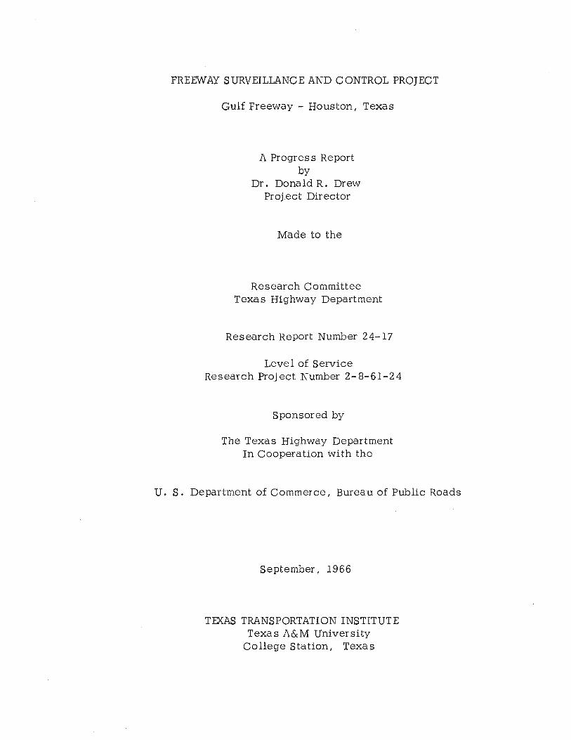
A similar closed circuit television system now exists for a six-mile section of the Gulf Freeway. It will permit complete surveillance of the traffic flow as well as the expedient handling of accidents or stalled vehicles on the freeway. The television monitors are housed in the central control center shown in Figure 1.
Freeway Control
Making better use of traffic facilities has long been a basic concept of the traffic engineer. However, the installation of access controls on freeways to obtain better traffic flow was not originally conceived for these facilities. The rapid growth of traffic demand in our urban areas, coupled with the long-term construction requirements for building an extensive urban freeway system, has required the application of a control concept to freeway operation.
Almost any engineering problem may be described as a systematic attempt to resolve a capacity-demand relationship at an acceptable level of service. We try to build enough strength into the materials of a layered pavement system, for example, to withstand shear stresses due to anticipated loads. However, the mere
MONITOR ARRANGEMENT IN CENTRAL CONTROL CENTER
FIGURE 1
fact that the strength (capacity) exceeds the load stresses (demand) does not guarantee an acceptable level of service. The deflection, smoothness, texture and color contrast also affect the driver's ride and as such, are level of service factors that must be considered.
The traffic engineer's basic problem of resolving a capacity-demand relationship is similar to that of any other engineer: he must be able to either measure the parameters defining capacity and demand accurately enough to design for them, or he must be able to control them after the facility is designed. It is, of course, impossible to predict traffic demand accurately for some date in the future. Returning to the pavement design analogy: although the strength of the materials in a pavement can probably not be estimated as accurately as the capacity of a freeway lane, the pavement designer knows that the loads (demand) on the facility are controlled, and in most states limited by law. If urban freeways are to operate at the levels of service for which they were designed, the demand on these facilities must also be regulated.
Ramp Control
Because the control of vehicles entering the freeway, as against the control of vehicles already on the freeway, offers a more positive means of preventing congestion, considerable emphasis is being placed on the control of entrance ramps. Two types of degrees of control are possible; they are ( 1) the complete closure of the entrance ramp and ( 2) the control of the amount of entering traffic referred to as "metering."
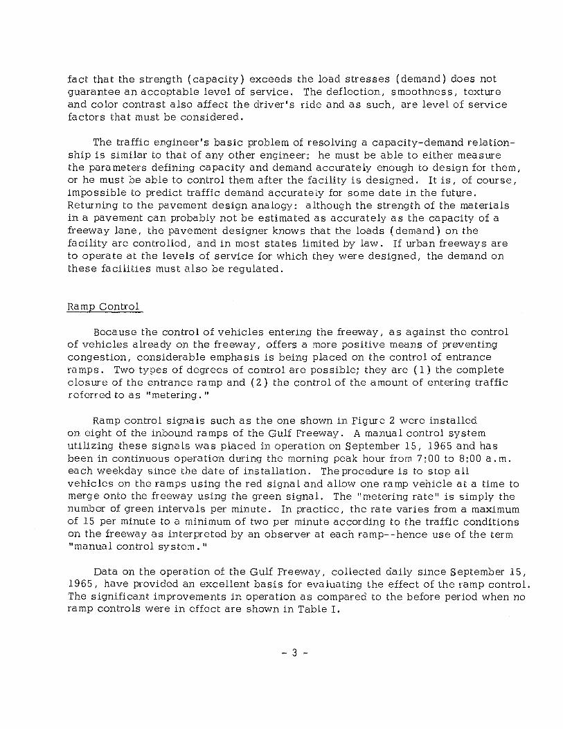
Ramp control signals such as the one shown in Figure 2 were installed on eight of the inbound ramps of the Gulf Freeway. A manual control system utilizing these signals was placed in operation on September 15, 1965 and has been in continuous operation during the morning peak hour from 7:00 to 8:00a.m. each weekday since the date of installation. The procedure is to stop all vehicles on the ramps using the red signal and allow one ramp vehicle at a time to merge onto the freeway using the green signal. The "metering rate" is simply the number of green intervals per minute. In practice, the rate varies from a maximum of 15 per minute to a minimum of two per minute according to the traffic conditions on the freeway as interpreted by an observer at each ramp--hence use of the term "manual control system."
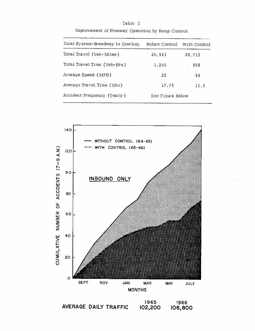
Data on the operation of the Gulf Freeway, collected daily since September 15, 1965, have provided an excellent basis for evaluating the effect of the ramp control. The significant improvements in operation as compared to the before period when no ramp controls were in effect are shown in Table I.
- 3 -
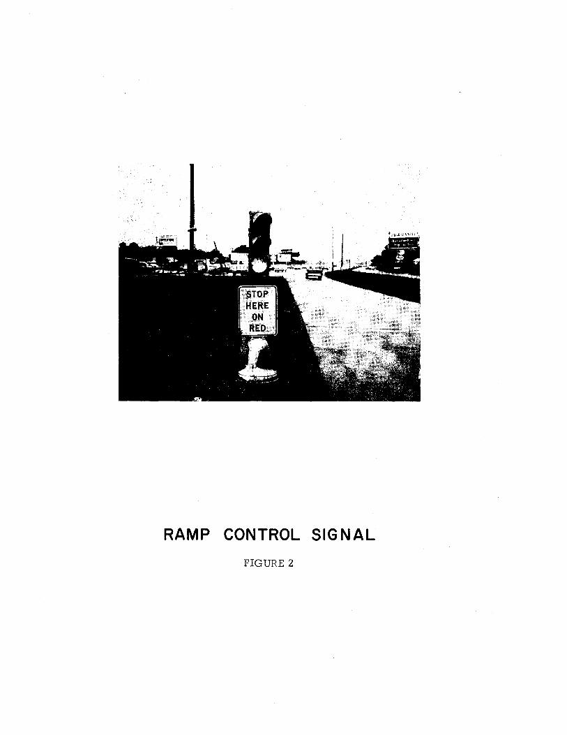
RAMP CONTROL SIGNAL
FIGURE 2
~ <(
m I
1'-
(/)
1-z w Cl (.) (.) <(
LL 0
0:: w al ~ => z w > 1-<( _J
=> ~ => (.)
Table I
Improvement of Freeway Operation by Ramp Control
Total System-Broadway to Dowling Before Control With Control
Total Travel (Veh-Miles) 26,913 28,713
Total Travel Time (Veh-Hrs) 1, 244 859
Average Speed (MPH) 22 34
AverageTravelTime (Min} 17.75 11.5
Accident Frequency (Yearly) See Figure Below
140
WITHOUT CONTROL (64-65)
WITH CONTROL (65-66) 120
90
INBOUND ONLY
80
60
40
20
0 SEPT NOV JAN MAR
MONTHS
AVERAGE DAILY TRAFFIC 1965
102,200
MAY JULY
1966 106,800

Automatic Ramp Control
In addition to research studies of the manual control system, developmental work was initiated on an automatic ramp control device which could replace the manual ramp control. Before an automatic ramp metering system is designed, its purposes and objectives should be considered. Assuming the proposed ramp metering system is both a research and an operational tool, it should involve the continuous sampling of basic traffic characteristics for interpretation by established parameters, in order to provide a quantitative knowledge of operating conditions necessary for immediate rational ramp control. In short: the system should be traffic responsive, and it should be automatic.
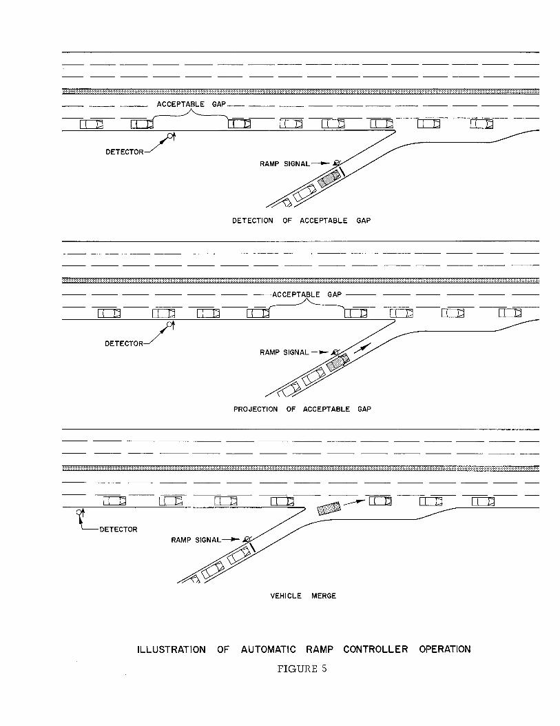
Functional specifications were developed for the controller shown in Figure 3. This controller called the "Gap Acceptance Mode 11 or Mode I detects gaps (or time spacing between vehicles) in the outside lane of the freeway upstream of an entrance ramp and evaluates the size of these gaps with regard to their ability to accommodate a vehicle entering from the ramp. When a desirable freeway gap is detected, it is projected downstream by means of a delay circuit to a point where a waiting vehicle on the entrance ramp can be merged into the gap. At this time, the signal on the ramp turns green and releases a ramp vehicle for a smooth merge into the freeway as shown in Figure 4. The functional process followed by the controller is illustrated in Figure 5.
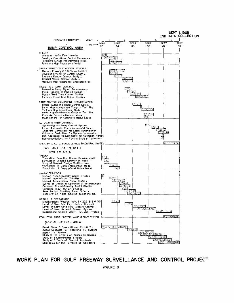
A second type of automatic ramp controller called the "Capacity-Demand Mode" or Mode II has been developed based on the capacity-demand relationships in the merging area. Final design specifications for an automatic ramp controller have been developed from the evaluation studies of the two prototype controllers. All lights of the inbound ramps are expected to be automatically controlling in thespring of 1967( see Figure 6).
- 6-

AUTOMATIC RAMP CONTROLLER FIGURE 3

RAMP VEHICLE MERGE FIGURE 4
-- --- --- --- --- --- ------------------- --
:·:·:·:·:·:·:·:·:·:·:·:·:·:·:·:·:·:·:·:·:·:·:·:·:·:·:·:·:·:·:·:·:·:·:·:·:·:·:·:·:·:·:·:·:·:·:·:·:·:·:·:·:·:·:·:·:·:·:·:·:·:·:·:·:·:·:·:·:·:·:·:-:-;.;.;.;.;.;.;.;.;.;.;.;.;.;.;.;.;.;.;.;.;.;.;.;.;.;.;.;.;.;.;.;.;-:-:-t.:-:·:·:·:·:·:·:·:·:·:·:·:·:·:·:·:·:·:
-- --- --- ACCEPTABLE GAP_-- __ --------------------
----- ~------------------- --[[]d COd o::::Jd [L]d [L]d [L]d c::c:Jd rr:Jd
DETECTOR/
DETECTION OF ACCEPTABLE GAP
-- ------ --- --- --- --- --- --- --- --- --- --- ---
-- --- --- --- --- --- --ACCEPTABLE GAP ---
[L]d- rr:Jd o:::Jd-~o:::Jd
DETECTORJ
PROJECTION OF ACCEPTABLE GAP
----- --- --- --- --- --- --- --- --
------
:·:-:-:-:-:-:-:-:-:·:·:·:·:·:·:·:·:·:·:·:·:·:·:·:·:·:·:·:·:·:·:·:·:·:·:·:·:·:·:·:·:·:·:·:·:·:·:·:·:·:·:·:·:·:·:·:·:·:·:·:·:·:·:·:·:·:·:·:·:·:·:·:·:·:·:·:·:·:·:·:·:·:·:·:·:·:·:·:·:·:·:·:·:·:·:·:·:·:·:·:·:·:·:·:·:·:·:·:·:·:·:·:·:·:·:·:·:·:·:·:·:·:·:·:·:·:·:
LDETECTOR
u=TI _____ =II==D~----
VEHICLE MERGE
ILLUSTRATION OF AUTOMATIC RAMP CONTROLLER OPERATION
FIGURE 5
SEPT. 1,1968 END DATA COLLECTION
RESEARCH ACTIVITY YEAR --.. 2 3 4 0 I Tl ME ___... SE_P_T_.:___S_E-:P:-::T:-. -=--:Sc::Ec:-P=cT-"---s=-=E=P=T:---'---:cS=cEP::cT.=c. __.'-- SEPT ~
RAMP CONTROL AREA ~ M ~ ~ ~ ~
THEORY Evaluate Traffic Flow Theories Develope Operational Control Parameters Formulate Linear Programming Model Formulate Gap Acceptance Model
CHARACTERISTICS 8 MANUAL STUDIES Measure Freeway 0 8 D Characteristics Develope Criteria for Control Study I Evaluate Manual Control Study I Conduct Manual Control Study II Measure Gap Acceptance Characteristics
FIXED TIME RAMP CONTROL Determine Ramp Signal Requirements Install Signals on Inbound Ramps Design Fixed Time Control Studies Evaluate Fixed Time Contol Studies
RAMP CONTROL EQUIPMENT REQUIREMENTS Design Automatic Ramp Control Equip. Install Gap Acceptance Equip. at Test Site Evaluate Gap Acceptance Mode Install Capacity-Demand Equip. at Test Site Evaluate Capacity-Demand Mode Modifications for Automatic Ramp Equip.
AUTOMATIC RAMP CONTROL Schematics for Ramp Control System Install Automatic Equip. on Inbound Ramps Calibrate Controllers for Local Optimization Calibrate Controllers for System Optimization Del. Additional Requirements for Outbound Ramps Recommendations for Central System Controller J
[. ~:<: . r.:. -"··· -~ ·:-J
E,·-•.e :: :··· r:
OPER. EVAL. AUTO. SURVEILLANCE 8 CONTROL SYSTEM ---+-----j----+-----t·,_,·-·"':"s-"""' ... '-' ... "-,.4 ...
FWY. -ARTERIAL STREET SYSTEM AREA
THEORY Theoretical Peak Hour Control Considerations Formulation Demand Estimation Model Study of Needed Design Modifications Formulation of Energy-Momentum Model Formulation of Energy-Accel. Noise Model
CHARACTERISTICS Inbound Speed-Density Aerial Studies Inbound Input- Output Studies Inbound Acceleration Noise Studies Survey of Design 8 Operation of Interchanges Outbound Speed-Density Aerial Studies Outbound Input-Output Studies Peak Period Starting_ Time Effects Acceleration Noise Studies Telephone Rd.
DESIGN 8 OPERATIONS Modifications Wayside Inch., S.H. 225 8 S.H. 35 Level of Serv. lnb. Fwy. (Before Cantrall Level of Serv. Out b. Fwy. (Before Control) Level of Serv. Arterial Street System Recommend Overall Modif. Fwy.-Art. System
ECON. EVAL. AUTO. SURVEILLANCE 8 CONT. SYSTEM
SPECIAL STUDIES AREA
Devel. Plans 8 Specs. Closed Circuit T.V. Award Contract For Installing TV. System I nsta II T.V. System Study of the Effects of Trucks on Grades Study of Environmental Effects Study of Effects of Special Incidents Strategies for Min. Effects of Accidents
WORK PLAN FOR GULF FREEWAY SURVEILLANCE AND CONTROL PROJECT FIGURE 6