freelander 2003my electrical library - eng - · pdf fileelectrical library lrl 0585eng ......
TRANSCRIPT

Electrical Library

FREELANDER 2003 MY
ELECTRICAL LIBRARY
LRL 0585ENGPublished by Land Rover
© Land Rover 2002All rights reserved. No part of this publication may be reproduced, stored in a retrieval system or transmitted in any form, electronic, mechanical,
recording or other means without prior written permission from Land Rover.

CONTENTS
FREELANDER 03MY 1
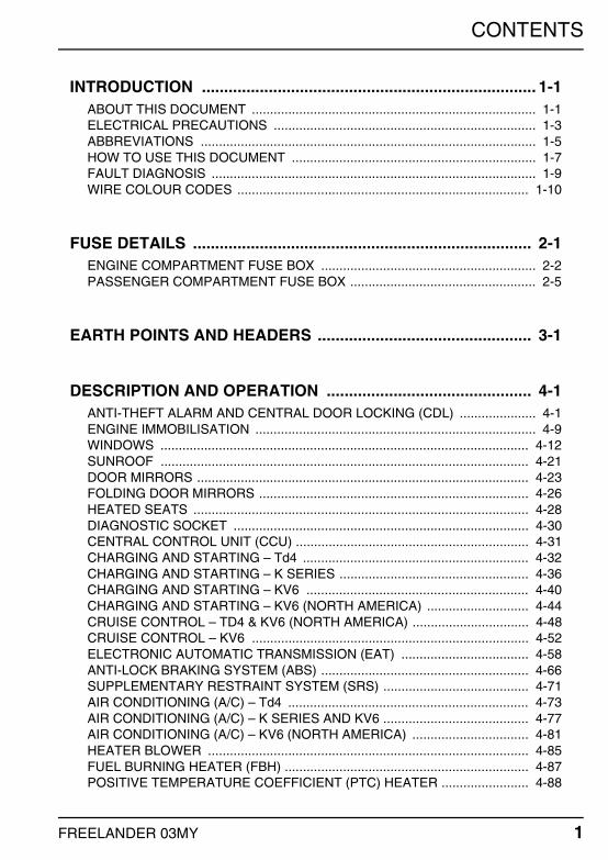
INTRODUCTION ........................................................................... 1-1ABOUT THIS DOCUMENT .............................................................................. 1-1ELECTRICAL PRECAUTIONS ........................................................................ 1-3ABBREVIATIONS ............................................................................................ 1-5HOW TO USE THIS DOCUMENT ................................................................... 1-7FAULT DIAGNOSIS ......................................................................................... 1-9WIRE COLOUR CODES ................................................................................ 1-10
FUSE DETAILS ............................................................................ 2-1ENGINE COMPARTMENT FUSE BOX ........................................................... 2-2PASSENGER COMPARTMENT FUSE BOX ................................................... 2-5
EARTH POINTS AND HEADERS ................................................ 3-1
DESCRIPTION AND OPERATION .............................................. 4-1ANTI-THEFT ALARM AND CENTRAL DOOR LOCKING (CDL) ..................... 4-1ENGINE IMMOBILISATION ............................................................................. 4-9WINDOWS ..................................................................................................... 4-12SUNROOF ..................................................................................................... 4-21DOOR MIRRORS ........................................................................................... 4-23FOLDING DOOR MIRRORS .......................................................................... 4-26HEATED SEATS ............................................................................................ 4-28DIAGNOSTIC SOCKET ................................................................................. 4-30CENTRAL CONTROL UNIT (CCU) ................................................................ 4-31CHARGING AND STARTING – Td4 .............................................................. 4-32CHARGING AND STARTING – K SERIES .................................................... 4-36CHARGING AND STARTING – KV6 ............................................................. 4-40CHARGING AND STARTING – KV6 (NORTH AMERICA) ............................ 4-44CRUISE CONTROL – TD4 & KV6 (NORTH AMERICA) ................................ 4-48CRUISE CONTROL – KV6 ............................................................................ 4-52ELECTRONIC AUTOMATIC TRANSMISSION (EAT) ................................... 4-58ANTI-LOCK BRAKING SYSTEM (ABS) ......................................................... 4-66SUPPLEMENTARY RESTRAINT SYSTEM (SRS) ........................................ 4-71AIR CONDITIONING (A/C) – Td4 .................................................................. 4-73AIR CONDITIONING (A/C) – K SERIES AND KV6 ........................................ 4-77AIR CONDITIONING (A/C) – KV6 (NORTH AMERICA) ................................ 4-81HEATER BLOWER ........................................................................................ 4-85FUEL BURNING HEATER (FBH) ................................................................... 4-87POSITIVE TEMPERATURE COEFFICIENT (PTC) HEATER ........................ 4-88

CONTENTS
2 FREELANDER 03MY
COOLING FANS ............................................................................................ 4-90HEATED REAR WINDOW (HRW) ................................................................. 4-93HEATED FRONT SCREEN (HFS) ................................................................. 4-96WIPERS AND WASHERS ............................................................................. 4-98BRAKE AND REVERSE LAMPS ................................................................. 4-103HEAD, SIDE AND TAIL LAMPS ................................................................... 4-106HEAD, SIDE AND TAIL LAMPS – CANADA ................................................ 4-110FOG LAMPS ................................................................................................ 4-114DIRECTION INDICATOR/HAZARD WARNING LAMPS .............................. 4-116INTERIOR LAMPS ....................................................................................... 4-118INTERIOR ILLUMINATION .......................................................................... 4-122INSTRUMENTS ........................................................................................... 4-124HORNS ........................................................................................................ 4-129REMOTE DISPLAY / CLOCK ...................................................................... 4-130CIGAR LIGHTER ......................................................................................... 4-131ACCESSORY SOCKET ............................................................................... 4-132AUDIO SYSTEM – LOW LINE ..................................................................... 4-133AUDIO SYSTEM – MID LINE ....................................................................... 4-136NAVIGATION SYSTEM ............................................................................... 4-140FUEL PUMP ................................................................................................. 4-145ROTARY COUPLER .................................................................................... 4-148
CONNECTOR ............................................................................... 5-1CIRCUIT REFERENCE NUMBERS ................................................................. 5-1

INTRODUCTION
FREELANDER 03MY 1.1
INTRODUCTION
ABOUT THIS DOCUMENTGeneralThis document is intended to assist in diagnosing electrical faults, and should be used in conjunction with the Electrical Circuit Diagrams. The document is divided into the following sections.
1. INTRODUCTION – Includes Electrical Precautions, a list of Abbreviations and general information on how to use this document.
2. FUSE DETAILS – Provides details of location, rating in Amperes, and circuit(s) protected.
3. EARTH POINTS AND HEADERS – Provides details of earth points and earth headers, including a plan view of the vehicle to aid location.
4. DESCRIPTION AND OPERATION – Provides an explanation of how each of the systems operate.
5. CIRCUIT REFERENCE NUMBERS – Provides a list of circuit reference numbers against a model or feature to which they apply.
6. CONNECTOR DETAIL – Details of connectors including a location photograph, face view and pin-out table.
NOTE: Before starting electrical checks on the vehicle, ensure that relevant mechanical functions operate satisfactorily.
ReferencesReferences to the LH or RH side given in this document are made when viewing the vehicle from the rear.
Operations covered in this document do not include reference to testing the vehicle after repair. It is essential that work is inspected and tested after completion and, if necessary, a road test of the vehicle is undertaken, particularly where safety related items are concerned.
CAUTION: Before undertaking any electrical work on a vehicle ALWAYS read the ELECTRICAL PRECAUTIONS.

INTRODUCTION
1.2 FREELANDER 03MY
Battery VoltageOpen Circuit Voltage TestBefore commencing diagnosis of electrical problems, verify the condition of the battery is acceptable by using the open circuit voltage test.
1. Switch off all electrical loads on the vehicle.2. Adjust digital multimeter to read dc volts on the appropriate scale.3. Connect test probes across battery terminals ensuring that polarity is correct and
record the voltage displayed.
A reading of 12.3 V or more is acceptable; any battery which reads less than this will need charging.
NOTE: If the vehicle has been used within a period of 8 hours prior to the test, surface charge must be removed from the battery by switching the headlamps on for approximately 30 seconds. Wait a further 60 seconds before checking the open circuit voltage.
Battery voltage is used as a known reference for ascertaining whether or not circuits are receiving sufficiently high voltage for components to function correctly. This reference is only a guide since most electronic circuits are designed to function over a wide range of voltages. In addition, consideration must be given to readings affected by voltage drop across certain components and fluctuations due to cable lengths.

INTRODUCTION
FREELANDER 03MY 1.3
ELECTRICAL PRECAUTIONSGeneralThe following guidelines are intended to ensure the safety of the operator whilst preventing damage to the electrical and electronic components fitted to the vehicle. Where necessary, specific precautions are detailed in the relevant sections of this document, reference of which should be made prior to commencing repair operations.
Equipment – Prior to commencing any test procedure on the vehicle, ensure that the relevant test equipment is working correctly and any harness or connections are in good condition. This particularly applies to mains lead or connections.
WARNING: Before commencing work on an ignition system, all high tension terminals, adaptors and diagnostic equipment for testing should be inspected to ensure that they are adequately insulated and shielded to prevent accidental personal contact and to minimise the risk of shock. Wearers of surgically implanted pacemaker devices should not work in close proximity to ignition circuits or diagnostic equipment.
Polarity – Never reverse connect the vehicle battery and always observe correct polarity when connecting test equipment.
High Voltage Circuits – Whenever disconnecting live ht circuits, always use insulated pliers and never allow the open end of the ht lead to come into contact with other components, particularly ECU's. Since high voltage spikes can occur on the terminals of the coil while the engine is running, exercise caution when measuring the voltage at these points.
Connectors and Harnesses – The engine compartment of a vehicle is a particularly hostile environment for electrical components and connectors. Always ensure these items are dry and oil free before disconnecting and connecting test equipment. Never force connectors apart either by using tools or by pulling on the wiring harness. Always ensure locking tabs are disengaged before removal and note orientation to enable correct reconnection. Ensure that any protective covers and substances are replaced if disturbed.
Before removing a faulty component, refer to the Workshop Manual for removal procedures. Ensure the ignition switch is turned to the 'OFF' position, the battery is disconnected (see Battery Disconnecting) and any disconnected harnesses are supported to avoid any undue strain at the terminals. When replacing the component keep oily hands away from electrical connection areas and push connectors home until any locking tabs fully engage.

INTRODUCTION
1.4 FREELANDER 03MY
Battery DisconnectingBefore disconnecting the battery, switch off all electrical equipment. If the radio is to be serviced, ensure the security code has been deactivated. When the battery is disconnected, certain data such as radio code and clock time will be lost.
CAUTION: To prevent damage to electrical components, ALWAYS disconnect the battery when working on the vehicle electrical systems. The earth lead must be disconnected first and reconnected last. Always ensure that battery leads are routed correctly and are not close to any potential chafing points.
Battery ChargingRecharge the battery out of the vehicle and keep the top well ventilated. While being charged or discharged, and for approximately fifteen minutes afterwards, batteries emit hydrogen gas. This gas is inflammable.
Always ensure any battery charging area is well ventilated and that every precaution is taken to avoid flames and sparks.
DisciplinesSwitch off ignition prior to making any connection or disconnection in the system as electrical surge caused by disconnecting 'live' connections can damage electrical components.
Ensure hands and work surfaces are clean and free of grease, swarf, etc. as grease collects dirt which can cause tracking or high-resistance contacts.
When handling printed circuit boards, treat them as you would a disc – hold by the edges only; note that some electrical components are susceptible to body static.
Connectors should never be subjected to forced removal or refit, especially inter-board connectors. Damaged contacts will cause short-circuit and open-circuit conditions.
Prior to commencing testing, and periodically during testing, touch a good earth, i.e. cigar lighter socket, to discharge body static as some electrical components are vulnerable to static electricity.
Grease for Electrical ConnectorsSome under bonnet and under body connectors are protected against corrosion by the application of a special grease during production. Should connectors of this type be disturbed, repaired, or replaced, a grease of this type, available under part number BAU 5811, should again be applied. Do not apply grease to any connectors that do not have grease applied as standard.
NOTE: The use of other greases must be avoided as they can migrate into relays, switches, etc. contaminating the contacts and leading to intermittent operation or failure.
INTRODUCTION
FREELANDER 03MY 1.5
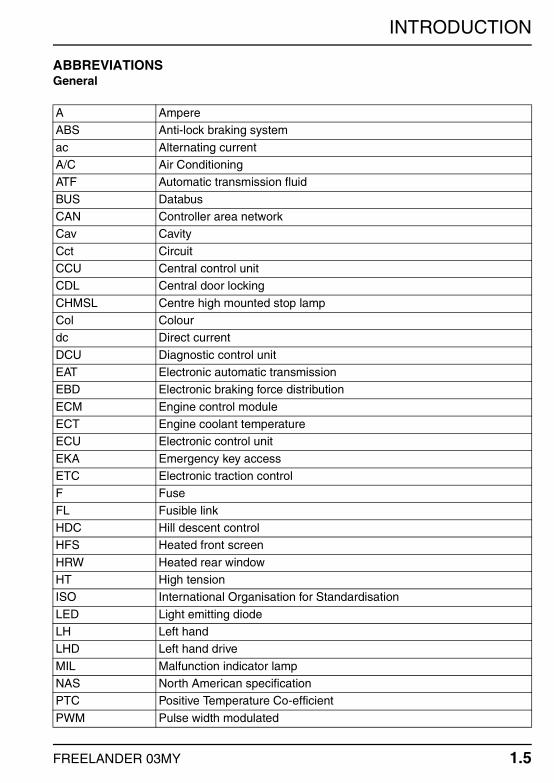
ABBREVIATIONSGeneral
A AmpereABS Anti-lock braking system
ac Alternating currentA/C Air ConditioningATF Automatic transmission fluid
BUS DatabusCAN Controller area networkCav Cavity
Cct CircuitCCU Central control unitCDL Central door locking
CHMSL Centre high mounted stop lampCol Colourdc Direct current
DCU Diagnostic control unitEAT Electronic automatic transmissionEBD Electronic braking force distribution
ECM Engine control moduleECT Engine coolant temperatureECU Electronic control unit
EKA Emergency key accessETC Electronic traction controlF Fuse
FL Fusible linkHDC Hill descent controlHFS Heated front screen
HRW Heated rear windowHT High tensionISO International Organisation for Standardisation
LED Light emitting diodeLH Left handLHD Left hand drive
MIL Malfunction indicator lampNAS North American specificationPTC Positive Temperature Co-efficient
PWM Pulse width modulated

INTRODUCTION
1.6 FREELANDER 03MY
R RelayRF Radio frequency
RH Right handRHD Right hand driveROW Rest of world
SRS Supplementary restraint systemV VoltVIN Vehicle identification number
W Watt

INTRODUCTION
FREELANDER 03MY 1.7
HOW TO USE THIS DOCUMENTFuse DetailsContains information on fuse functions and values and should be used together with the power distribution circuit diagrams to establish which systems share a common power supply and to ensure that correct value fuses are fitted.
Earth Points and HeadersShows a plan view of the vehicle with location of all earth points. Supporting photographs and connector detail information appear in the Connector section.
Description and OperationPresented in the same order as the circuit diagrams in the Electrical Circuit Diagram folder, each of the descriptions contains a brief overview of the main system functions and includes reference to the appropriate wire colours. Always read this section before starting work on a system so that a good understanding of system functionality is obtained.
Connector DetailsThis section is effectively an index of every electrical connector on the vehicle, including headers and eyelets. A page is dedicated to each connector, with the information presented in a standard format. The connector number is displayed on each page header to ease reference. Connector information comprises:
Connector Number – The assigned number, prefixed 'C'.Connector Name – Usually derived from the component to which the connection is made.Male/Female – If applicable, identifies the gender of the connector pins (NOT the housing) as Male or Female. Generally, connectors mating directly into a component have Female pins.Colour – If applicable, the colour of the connector housing is shown. NATURAL is used to describe connectors with a clear/translucent plastic finish.Location Statement – Used in conjunction with the photograph to determine the location of the connector.Photograph – Shows the location of the subject connector. In most cases the photograph will indicate the amount of trim removal necessary to reveal the connector. For convenience some photographs identify more than one connector.Face View – An outline of the connector housing, viewed from the front, showing pin numbers (if applicable).Pin-out Table – A three column table, detailing the colour and position of each wire in the connector:

INTRODUCTION
1.8 FREELANDER 03MY
1. Cav: The connector pin (cavity) number.2. Col: The colour of wire populating the connector pin.3. Cct: Identifies the model or feature which uses the wire. 'ALL' means applicable to all
models in the range fitted with the feature or system in question. In instances where different models, features or systems require different colour wires to be fitted in a cavity, each instance of the cavity is included in the pin-out table.
NOTE: Wires may not be fitted to all cavities.
Example – 12 Pin Connector
Where necessary, a table listing the circuit reference numbers against a description of the model or features which may or may not be fitted can be found at the beginning of the connector section. A sample of a typical table is shown below.
Cav Col Cct1 GR ALL2 B ALL
Cav Col Cct2 G ALL4 GW 8
4 GB 104 GR 125 LGB ALL
6 GB 86 GW 106 GR 12
8 B ALL
Cct Model or Feature1 3 Door2 5 Door3 LHD
4 RHD5 Japanese vehicles only6 NAS vehicles only
7 Australian vehicles only

INTRODUCTION
FREELANDER 03MY 1.9
FAULT DIAGNOSISGeneralWhen diagnosing an electrical fault, follow the steps below:
1. Read the circuit description appropriate to the reported fault to ensure a good understanding of circuit operation.
2. Study the power distribution, fuse details and earth distribution diagrams and identify other circuits which share fuses and/or earth points. Check whether these circuits operate correctly.
3. Using the photographs contained in the Connector section, locate a point on the circuit (approximately half way between supply and earth) which is easily accessible.
4. Check that the pin-out details of the connector are correct and that the correct signals exist at the correct terminals.
5. Using the marker pen supplied (or other suitable non-permanent marker pen), mark the parts of the circuit you have verified.
6. Continue to the next point on the circuit which is easiest to access and repeat the above.
7. Continue with this approach until a fault is found, rectify the fault and then verify that the circuit operates correctly.
CAUTION: Never probe directly into the front face of a connector. This can damage the terminal and cause a failure. Always probe the back of a terminal, taking care not to damage the terminal or any seals.
Never probe wire insulation. On small diameter cables this can cut the conductors. It may also allow moisture into the cable, causing corrosion.

INTRODUCTION
1.10 FREELANDER 03MY
WIRE COLOUR CODESGeneralThe following list contains wire colour codes used on the vehicle harness's.
Code ColourB BlackG Green
K PinkLG Light greenN Brown
O OrangeP PurpleR Red
S Slate (Grey)T TransparentU Blue
W WhiteY Yellow

FUSE DETAILS
FREELANDER 03MY 2.1
FUSE DETAILS
IntroductionFuses are mounted in one of two fuse boxes. One fuse box is located in the LH rear side of the engine compartment, and the other is located behind the driver side cubby box.
The engine compartment fuse box contains three different types of fuse:
1. Blade type fuse – Small, pull out, male fuse, used to protect circuits from 5 A to 30 A.2. J–case fuse – Square shaped, pull out, female fuse, used to protect circuits from 30
A to 60 A.3. Bolt down fuse – Also known as a fusible link, used to protect circuits from 40 A to
250 A.
The passenger compartment fuse box contains blade type fuses only.
WARNING: Contained within the passenger compartment fuse box is the SRS fuse. This is identifiable by its yellow cover. Do not carry out any work on the SRS system before reading the SRS warnings, cautions, and notes contained within the Introduction section of the Workshop manual.

FUSE DETAILS
2.2 FREELANDER 03MY
ENGINE COMPARTMENT FUSE BOX
Relays (R)1. Fuel pump relay.2. Starter relay.3. HDC relay.4. Main relay.5. ECM relay (NAS only).6. Horn relay.7. A/C compressor clutch relay.
FUSE DETAILS
FREELANDER 03MY 2.3
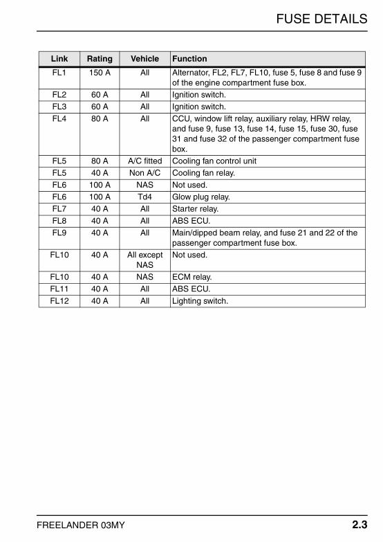
Link Rating Vehicle Function
FL1 150 A All Alternator, FL2, FL7, FL10, fuse 5, fuse 8 and fuse 9 of the engine compartment fuse box.
FL2 60 A All Ignition switch.FL3 60 A All Ignition switch.
FL4 80 A All CCU, window lift relay, auxiliary relay, HRW relay, and fuse 9, fuse 13, fuse 14, fuse 15, fuse 30, fuse 31 and fuse 32 of the passenger compartment fuse box.
FL5 80 A A/C fitted Cooling fan control unitFL5 40 A Non A/C Cooling fan relay.
FL6 100 A NAS Not used.FL6 100 A Td4 Glow plug relay.FL7 40 A All Starter relay.
FL8 40 A All ABS ECU.FL9 40 A All Main/dipped beam relay, and fuse 21 and 22 of the
passenger compartment fuse box.FL10 40 A All except
NASNot used.
FL10 40 A NAS ECM relay.FL11 40 A All ABS ECU.
FL12 40 A All Lighting switch.

FUSE DETAILS
2.4 FREELANDER 03MY
Fuse Rating Vehicle Function
F1 15 A Td4 Glow plug relay.F1 15 A K1.8 Purge control valve, HO2S
F1 15 A KV6 HO2S, splice joint 14.F1 15 A NAS Fuel pump, splice joint 14.F2 20 A Td4 ECM.
F2 20 A K1.8 ECM, fuel injectors, splice joint 1.F2 20 A KV6 ECM, fuel injectors, splice joint 15.F2 20 A NAS ECM, header 294.
F3 15 A K1.8 Splice joint 2F3 15 A KV6 Splice joint 13.F3 15 A NAS Header 294.
F4 15 A Td4 Splice joint 51, A/C compressor clutch relay, E-Box temperature sensor, cooling fan control unit.
F4 15 A K1.8 Splice joint 51, A/C compressor clutch relay, cooling fan control unit, cooling fan relay, E-box temperature sensor.
F4 15 A KV6 Splice joint 51, A/C compressor clutch relay, cooling fan control unit, E-box temperature sensor.
F4 15 A NAS Splice joint 51, A/C compressor clutch relay, E-box temperature sensor.
F5 20 A Td4 ECM, fuel burning heater.
F5 20 A K1.8, KV6 & NAS
ECM.
F6 15 A All Horn relay.F7 15 A All Splice joint 12.F8 30 A All Blower motor relay.
F9 10 A All A/C compressor clutch relay.F10 20 A Td4 Inertia switch.F10 10 A K1.8, KV6 &
NASInertia switch.

FUSE DETAILS
FREELANDER 03MY 2.5
PASSENGER COMPARTMENT FUSE BOX
Relays (R)1. Main/Dipped beam relay2. HRW relay3. Accessory socket relay4. Auxiliary relay5. Window lift relay6. Flasher unit
FUSE DETAILS
2.6 FREELANDER 03MY
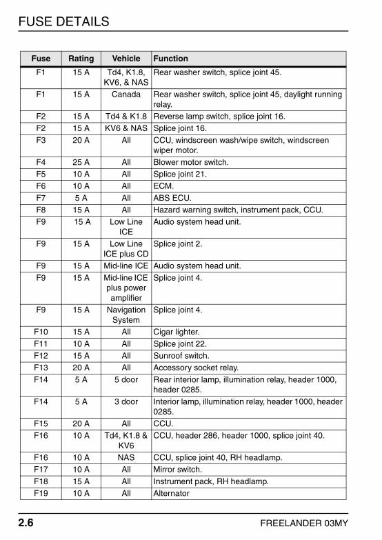
Fuse Rating Vehicle Function
F1 15 A Td4, K1.8, KV6, & NAS
Rear washer switch, splice joint 45.
F1 15 A Canada Rear washer switch, splice joint 45, daylight running relay.
F2 15 A Td4 & K1.8 Reverse lamp switch, splice joint 16.F2 15 A KV6 & NAS Splice joint 16.
F3 20 A All CCU, windscreen wash/wipe switch, windscreen wiper motor.
F4 25 A All Blower motor switch.F5 10 A All Splice joint 21.F6 10 A All ECM.
F7 5 A All ABS ECU.F8 15 A All Hazard warning switch, instrument pack, CCU.F9 15 A Low Line
ICEAudio system head unit.
F9 15 A Low Line ICE plus CD
Splice joint 2.
F9 15 A Mid-line ICE Audio system head unit.
F9 15 A Mid-line ICE plus power amplifier
Splice joint 4.
F9 15 A Navigation System
Splice joint 4.
F10 15 A All Cigar lighter.
F11 10 A All Splice joint 22.F12 15 A All Sunroof switch.F13 20 A All Accessory socket relay.
F14 5 A 5 door Rear interior lamp, illumination relay, header 1000, header 0285.
F14 5 A 3 door Interior lamp, illumination relay, header 1000, header 0285.
F15 20 A All CCU.F16 10 A Td4, K1.8 &
KV6CCU, header 286, header 1000, splice joint 40.
F16 10 A NAS CCU, splice joint 40, RH headlamp.F17 10 A All Mirror switch.
F18 15 A All Instrument pack, RH headlamp.F19 10 A All Alternator

FUSE DETAILS
FREELANDER 03MY 2.7
F20 15 A All LH headlamp.F21 15 A All Not used.F22 10 A All Rear fog lamp relay.
F23 20 A All HRW, HRW switch.F24 10 A All LH headlamp.F25 10 A All RH headlamp.
F26 20 A All LH window switch.F27 20 A All RH window switch.F28 10 A Td4, K1.8, &
KV6LH headlamp, LH headlamp levelling motor, LH tail lamp, trailer pick-up, headlamp levelling switch.
F28 10 A NAS LH headlamp, LH tail lamp, trailer pick-up.
F29 20 A All Splice joint 44.F30 10 A All Rear wiper relay.F31 20 A All Tail door window lift relay.
F32 5 A All Engine immobilisation ECU.F33 20 A All Splice joint 28.F34 20 A All RH front window switch.
F35 10 A All Header 292.F36 10 A All SRS DCU.
Fuse Rating Vehicle Function

FUSE DETAILS
2.8 FREELANDER 03MY

EARTH POINTS AND HEADERS
FREELANDER 03MY 3.21
EARTH POINTS AND HEADERS
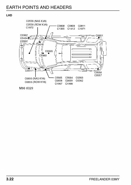
GeneralThe following illustrations indicate the general position of each earth point and header on the vehicle. Refer to the Connector section for more information.
Refer to the Circuit Diagrams for details of electrical components and their associated earth points.RHD
EARTH POINTS AND HEADERS
3.22 FREELANDER 03MY
LHD
DESCRIPTION AND OPERATION
FREELANDER 03MY 4.1
DESCRIPTION AND OPERATION
ANTI-THEFT ALARM AND CENTRAL DOOR LOCKING (CDL)
DESCRIPTIONGeneralThe anti-theft alarm system is controlled by the Central Control Unit (CCU), which is mounted on the rear of the passenger compartment fuse box. The alarm can be armed and disarmed using the vehicle key or remote handset. The two main features of the alarm system are:
Perimetric protection.Volumetric protection.
Perimetric ProtectionPerimetric protection secures against intrusion through the bonnet, doors, tail door or roof. The CCU monitors the state of the hinged panels after the alarm system has been armed. If a panel is opened after the alarm has been armed, the alarm will be triggered.
Switches are incorporated into the door latch assemblies, the bonnet, and the tail door. Three door vehicles also have a 'roof on' switch, to inform the CCU if the hard back has been removed, or the soft back is opened.
Perimetric protection is initiated after a valid alarm request is received. If any panel is open when perimetric protection is activated (other than the roof), the alarm will enter a partially armed state.
Volumetric ProtectionVolumetric protection provides protection for the vehicle interior. A volumetric sensor monitors the vehicle interior space and activates the alarm if unauthorised movement is detected. The volumetric sensor is located in a central position, behind the headlining.
A fifteen second delay is initiated after the alarm has been armed before signals from the volumetric sensor are interpreted as an intrusion. This precaution is included in the CCU software to avoid accidental or nuisance triggering of the alarm.
For a detailed description of the anti-theft alarm system, refer to the Security section of the System Description and Operation Workshop manual.

DESCRIPTION AND OPERATION
4.2 FREELANDER 03MY
OPERATIONGeneralFeed from the positive battery terminal (C0192) is supplied to the horn relay, fuse 6, fuse 7, fuse 10, and fusible link 4 (C0632) on an R wire. All are located in the engine compartment fuse box. Fuse 10 (C0575) provides a constant battery feed to the inertia switch (C0123) on a G wire. Fuse 7 (C0576) provides a constant battery feed to the hazard warning relay located in the passenger compartment fuse box (C0581) on an NO wire.
Fusible link 4 (C0574) provides a constant battery feed to the CCU (C0593) and fuse 14 of the passenger compartment fuse box (C0581) on an NW wire. Fuse 14 (C0589) provides a feed to the alarm LED located in the instrument pack (C0230) and the transponder coil mounted around the ignition barrel (C0049) on P wires. Fuse 14 (C0583) also provides a feed to the diagnostic socket (C0040) and the roof on switch (3 door vehicles only) (C0497) on P wires.
Door SwitchesIn order for the perimetric alarm system to operate, the CCU monitors the condition of the door switches (including the tail door switch). The door switches are open circuit when the doors are closed. When the doors are opened, the switches close and an earth path is created. The CCU (C0428) is connected to the door switches as follows:
To the driver door switch (C0441) on a PS then PW wire.To the passenger door switch (C0441) on a PW wire.To the LH rear door switch (C0442) on a PW wire.To the RH rear door switch (C0442) on a PW wire.To the tail door switch (C0616) on a BO wire.
NOTE: Both front and both rear door switches have the same connector number as they utilise the same harness.
The CCU treats the passenger door, and both rear doors as a single item. All door switches are earthed on B wires.
Bonnet SwitchIn addition to the door switches, the CCU also monitors the condition of the bonnet switch. The bonnet switch is a normally open switch. When the bonnet is opened, the switch closes and an earth path is created.
The CCU (C0428) provides a feed to the bonnet switch (C0007) on an RP wire. The switch (C0007) is earthed on a B wire. By monitoring the state of the bonnet switch, the CCU can determine if the bonnet has been opened illegally and sound the alarm if necessary.

DESCRIPTION AND OPERATION
FREELANDER 03MY 4.3
Roof On Switch (3 Door Vehicles Only)The roof on switch (C0497) is located on the RH 'D' post, and is provided a constant battery feed by fuse 14 of the passenger compartment fuse box (C0583) on a P wire. The roof on switch is closed when the hard back is fitted, or the soft back is in the fitted position. In this instance, current flows across the switch (C0497) to the CCU (C0428) on a PY wire.
If the hard back is removed (or the soft back is folded down) the roof on switch becomes open circuit, and the feed to the CCU is removed. By monitoring the state of the roof on switch, the CCU can determine if the roof has been opened illegally and sound the alarm if necessary.
Anti-theft Alarm LEDFuse 14 of the passenger compartment fuse box (C0589) provides a constant battery feed to the anti-theft alarm LED mounted in the instrument pack (C0230) on a P wire. The earth path for the LED (C0235) is controlled by the CCU (C0592) on a UK wire. By switching the earth path on and off, the CCU can control the flashing sequence of the LED.
Inertia SwitchFuse 10 of the engine compartment fuse box (C0575) provides a constant battery feed to the inertia switch (C0123) on a G wire. The inertia switch is a normally closed switch. The inertia switch (C0123) is connected to the CCU (C0428) via the engine compartment fuse box by a GU then UG wire.
When the inertia switch is tripped the switch opens, cutting the voltage supply to the CCU. Sensing this, the CCU unlocks all doors and cuts the electrical supply to the fuel pump.
NOTE: The CCU will only unlock all doors if the ignition is switched on, and the anti-theft alarm isn't armed.
For more information on the fuel pump, refer to the relevant Charging and Starting section of this manual. + CHARGING AND STARTING – Td4. + CHARGING AND STARTING – K SERIES. + CHARGING AND STARTING – KV6.

DESCRIPTION AND OPERATION
4.4 FREELANDER 03MY
Volumetric SensorThe CCU (C0429) provides a feed to the volumetric sensor (C0358 on 3 door vehicles, C1896 on 5 door vehicles) on a WB wire. When the alarm is armed, the volumetric sensor (C0358 on 3 door vehicles, C1896 on 5 door vehicles) returns a signal feed back to the CCU (C0428) on an NB wire. If the sensor detects movement within the vehicle, it withdraws the signal feed to the CCU. Sensing this, the CCU will sound the alarm.
The CCU (C0429) also provides a gain setting signal to the volumetric sensor (C0358 on 3 door vehicles, C1896 on 5 door vehicles) on an SW wire. This enables the volumetric sensor to determine if it is looking at the interior of a 3 door vehicle or a 5 door vehicle and adjust its sensitivity accordingly.
The volumetric sensor (C0358 on 3 door vehicles, C1896 on 5 door vehicles) is earthed on a B wire.
Radio Frequency (RF) ReceiverThe CCU (C0429) provides a feed to the RF receiver (C0359) on a Y wire. The RF receiver (C0359) provides a 12 V feed back to the CCU (C0428) on an S wire. When an RF signal is received from the remote handset, the receiver switches the feed back to the CCU between 12 V and 0 V at high frequency.
The RF receiver (C0359) is earthed on a B wire.
Master Lock SwitchThe master lock switch is a non-latching rocker switch mounted on the centre console, below the radio. When the bottom (lock) half of the switch is pressed, current is able to flow from the CCU (C0428) to the master lock switch (C0328) on a BN wire. Current flows across the closed switch contacts to earth on a B wire. The CCU will now lock all the doors.
NOTE: The alarm will not be armed when using the master lock switch.
When the top (unlock) half of the switch is pressed, current is able to flow from the CCU (C0428) to the master lock switch (C0328) on a BK wire. Current flows across the closed switch contacts to earth on a B wire. The CCU will now unlock all the doors.
Door Lock MotorsWhen the CCU receives a request to lock or unlock the doors, it powers the door lock motors as follows:

DESCRIPTION AND OPERATION
FREELANDER 03MY 4.5
Driver DoorTo lock the driver door, the CCU (C0430) provides a feed to the driver door lock motor (C0441) on a K wire. The motor (C0441) is provided an earth path via the CCU (C0430) on an O wire. This enables the motor to drive the latch to the lock position.
To unlock the driver door, the CCU (C0430) provides a feed to the driver door lock motor (C0441) on an O wire. The motor (C0441) is provided an earth path via the CCU (C0430) on a K wire. This enables the motor to drive the latch to the unlock position.
Passenger DoorTo lock the passenger door, the CCU (C0430) provides a feed to the passenger door lock motor (C0441) on a K wire. The motor (C0441) is provided an earth path via the CCU (C0430) on an O wire. This enables the motor to drive the latch to the lock position.
To unlock the passenger door, the CCU (C0430) provides a feed to the passenger door lock motor (C0441) on an O wire. The motor (C0441) is provided an earth path via the CCU (C0430) on a K wire. This enables the motor to drive the latch to the unlock position.
NOTE: The driver and passenger door lock motors have the same connector numbers as they utilise the same harness.
LH Rear DoorTo lock the LH rear door, the CCU (C0430) provides a feed to the LH rear door lock motor (C0442) on a K wire. The motor (C0442) is provided an earth path via the CCU (C0430) on an O wire. This enables the motor to drive the latch to the lock position.
To unlock the LH rear door, the CCU (C0430) provides a feed to the LH rear door lock motor (C0442) on an O wire. The motor (C0442) is provided an earth path via the CCU (C0430) on a K wire. This enables the motor to drive the latch to the unlock position.
RH Rear DoorTo lock the RH rear door, the CCU (C0430) provides a feed to the RH rear door lock motor (C0442) on a K wire. The motor (C0442) is provided an earth path via the CCU (C0430) on an O wire. This enables the motor to drive the latch to the lock position.
To unlock the RH rear door, the CCU (C0430) provides a feed to the RH rear door lock motor (C0442) on an O wire. The motor (C0442) is provided an earth path via the CCU (C0430) on a K wire. This enables the motor to drive the latch to the unlock position.
NOTE: The LH rear and RH rear door lock motors have the same connector numbers as they utilise the same harness.

DESCRIPTION AND OPERATION
4.6 FREELANDER 03MY
Tail DoorOperation of the tail door latch mechanism is only possible when the vehicle is stationary or travelling at speeds lower than 3 mph (5 km/h). To allow the tail door latch to operate, the CCU (C0430) provides a single voltage pulse to the tail door motor (C0617) on a PU wire. The motor (C0617) is earthed on a B wire.
The CCU receives a road speed signal from the ABS ECU. If road speed rises above 3 mph (5 km/h), the CCU will not provide a voltage pulse to the tail door motor, inhibiting operation of the tail door latch mechanism.
SuperlockingSuperlocking inhibits the use of the interior door handles in addition to driving the door lock motors to the lock position. When the CCU receives a request to superlock the doors, it supplies the following outputs in addition to those detailed above in the Door Lock Motors description.
NOTE: The vehicle will not start if the vehicle is superlocked. For more information, refer to the 'Engine Immobilisation' section of this manual.
+ ENGINE IMMOBILISATION.
Driver DoorTo superlock the driver door, the CCU (C0430) provides a feed to the driver door superlock motor (C0441) on an NK wire. The superlock motor (C0441) is provided an earth path via the CCU (C0430) on an O wire. This powers the superlock motor to the lock position, inhibiting the interior door handle.
To unlock the driver door from the superlock condition, the CCU (C0430) provides a feed to the driver door lock motor and the superlock motor (C0441) on an O wire. The driver door lock motor and the superlock motor (C0441) are provided an earth path via the CCU (C0430) on a K wire. This powers both motors to the unlock position.
Passenger DoorTo superlock the passenger door, the CCU (C0430) provides a feed to the passenger door superlock motor (C0441) on an NK wire. The superlock motor (C0441) is provided an earth path via the CCU (C0430) on an O wire. This powers the superlock motor to the lock position, inhibiting the interior door handle.
To unlock the passenger door from the superlock condition, the CCU (C0430) provides a feed to the passenger door lock motor and the superlock motor (C0441) on an O wire. The passenger door lock motor and the superlock motor (C0441) are provided an earth path via the CCU (C0430) on a K wire. This powers both motors to the unlock position.

DESCRIPTION AND OPERATION
FREELANDER 03MY 4.7
LH Rear DoorTo superlock the LH rear door, the CCU (C0430) provides a feed to the LH rear door superlock motor (C0442) on an NK wire. The superlock motor (C0442) is provided an earth path via the CCU (C0430) on an O wire. This powers the superlock motor to the lock position, inhibiting the interior door handle.
To unlock the LH rear door from the superlock condition, the CCU (C0430) provides a feed to the LH rear door lock motor and the superlock motor (C0442) on an O wire. The LH rear door lock motor and the superlock motor (C0442) are provided an earth path via the CCU (C0430) on a K wire. This powers both motors to the unlock position.
RH Rear DoorTo superlock the RH rear door, the CCU (C0430) provides a feed to the RH rear door superlock motor (C0442) on an NK wire. The superlock motor (C0442) is provided an earth path via the CCU (C0430) on an O wire. This powers the superlock motor to the lock position, inhibiting the interior door handle.
To unlock the RH rear door from the superlock condition, the CCU (C0430) provides a feed to the RH rear door lock motor and the superlock motor (C0442) on an O wire. The RH rear door lock motor and the superlock motor (C0442) are provided an earth path via the CCU (C0430) on a K wire. This powers both motors to the unlock position.
HornsIf the anti-theft alarm is triggered, the CCU (C0430) provides an earth path for the horn relay coil (C0576) on a PY wire. The energised horn relay (C0570 & C0576) provides a feed to the LH (C0003) and RH (C0004) horns on PB wires. The horns are earthed on B wires.
By switching the earth path for the relay coil on and off, the CCU can control the operation of the horns.

DESCRIPTION AND OPERATION
4.8 FREELANDER 03MY
Direction Indicator/Hazard Warning LampsIf the anti-theft alarm is triggered, the CCU (C0593) provides an earth path for the hazard warning relay coil. The energised hazard warning relay provides a feed to the following:
The LH rear direction indicator lamp (C0121) on a GR wireThe RH rear direction indicator lamp (C0125) on a GW wireThe LH front direction indicator lamp (C0009) on a GR wireThe RH front direction indicator lamp (C0011) on a GW wireThe trailer pick-up (C0499) on a GR and GW wire.
All are earthed on B wires, except the trailer pick-up which is earthed on a W then B wire.
By switching the earth path for the relay coil on and off, the CCU can control operation of the direction indicator lamps. For more information, refer to the Direction Indicator/Hazard Warning Lamps section of this manual. + DIRECTION INDICATOR/HAZARD WARNING LAMPS.
DESCRIPTION AND OPERATION
FREELANDER 03MY 4.9
ENGINE IMMOBILISATION
DESCRIPTIONGeneralThe function of the engine immobilisation system is to prevent unauthorised starting of the vehicle. The system is controlled by the immobilisation ECU, which is located behind the centre of the fascia. Re-mobilisation is achieved via a transponder in the vehicle key, which is read by a transponder coil when the ignition switch is turned to the 'auxiliary' position. The transponder coil is mounted around the ignition barrel.
For a detailed description of the engine immobilisation system, refer to the Security section of the System Description and Operation Workshop manual.
OPERATIONGeneralFeed from the positive battery terminal (C0192) is supplied to fusible link 1, fusible link 3, and fusible link 4 of the engine compartment fuse box (C0632) on an R wire. Fusible link 4 (C0574) is connected to fuse 32 of the passenger compartment fuse box (C0587) by an NW wire. Fuse 32 (C0584) provides a constant battery feed to the immobilisation ECU (C0059) on a PN wire.
Fusible link 3 (C0571) is connected to the ignition switch (C0028) by an N wire. When the ignition switch is turned to the 'auxiliary' position, current flows across the switch (C0028) to fuse 11 of the passenger compartment fuse box (C0588) on a PS wire. Fuse 11 (C0580) provides an auxiliary ignition feed to the Central Control Unit (CCU) (C0430) on an LGW wire.
When the ignition switch is turned to the 'crank' position, current flows across the switch (C0028) to fuse 5 of the passenger compartment fuse box (C0588) on a WR wire. Fuse 5 (C0581) provides a feed to the immobilisation ECU (C0059) on a WR wire. The immobilisation ECU (C0059) is earthed on a B wire.
Immobilisation ECU Inputs/OutputsThe immobilisation ECU receives inputs and outputs from a number of different components to ensure the right criteria are met before it will allow the engine to be started.

DESCRIPTION AND OPERATION
4.10 FREELANDER 03MY
Transponder CoilThe transponder coil (C0049) mounted around the ignition barrel, and is connected to the engine immobilisation ECU (C0059) by KB and KG wires. Both connections between the immobilisation ECU and the transponder coil switch between both inputs and outputs. The transponder coil reads the vehicle identification information contained within the key transponder and relays it to the immobilisation ECU. The immobilisation ECU (C0059) then compares this information with the vehicle identification information received from the Central Control Unit (CCU) (C0429) on a G wire.
Central Control Unit (CCU)The CCU (C0429) outputs a locking status signal to the immobilisation ECU (C0059) on a KN wire. If the vehicle has been superlocked or the anti-theft alarm system is armed, the immobilisation ECU issues a request for the CCU to remove both before it will allow the engine to be cranked.
NOTE: When the CCU receives a 'remove superlock' signal from the immobilisation ECU, it will unlock the driver door. Superlocking will be removed from the remaining doors if single point entry is selected.
For more information on superlocking and the anti-theft alarm system, refer to the Anti-theft Alarm and Central Door Locking (CDL) section of this manual. + ANTI-THEFT ALARM AND CENTRAL DOOR LOCKING (CDL).
The CCU also outputs an ignition status signal, informing the immobilisation ECU when the ignition switch has been turned to the 'ignition' position. The CCU (C0428) transmits this signal to the immobilisation ECU (C0059) on an ON wire.
Gearbox Solenoid (Automatic Vehicles Only)When the gear selector lever is in the Park (P) or Neutral (N) position, the gearbox solenoid (C0244) provides a feed to the immobilisation ECU (C0059) on a W wire. If the selector lever is moved to any other position, the feed is removed and the immobilisation ECU will not allow the engine to be cranked.
Engine Control Module (ECM)If the correct re-mobilisation code is received from the remote handset, the immobilisation ECU (C0059) transmits a rolling code to the ECM (C0331 on Td4 vehicles, C0913 on K Series vehicles, C0371 on KV6 vehicles) on a YR wire. The ECM (C0603 on Td4 vehicles, C0913 on K Series vehicles, C0371 on KV6 vehicles) will now energise the main relay by providing an earth path for the relay coil (C0576) on a WK wire.

DESCRIPTION AND OPERATION
FREELANDER 03MY 4.11
Starter RelayIf the vehicle has been successfully re-mobilised, the immobilisation ECU (C0059) provides a feed to the starter relay coil (C0576) on an RW wire. The relay coil (C0576) is earthed on a B wire. The energised relay allows a feed from fusible link 7 to flow across the relay switch contacts (C0572) to the starter motor (C0179) on an NR wire (NR then B on Td4 vehicles). For more details of starter motor operation, refer to the Charging and Starting – Td4 , Charging and Starting – K Series or Charging and Starting – KV6 sections of this manual. + CHARGING AND STARTING – Td4. + CHARGING AND STARTING – K SERIES. + CHARGING AND STARTING – KV6.
Diagnostic SocketThe diagnostic socket (C0040) is connected to the immobilisation ECU (C0059) by a K wire, enabling the immobilisation ECU to be interrogated by TestBook or T4.

DESCRIPTION AND OPERATION
4.12 FREELANDER 03MY
WINDOWS
DESCRIPTIONDoor WindowsThe front and rear electrically operated windows are opened and closed by using the appropriate non-latching switch mounted on the centre console. Rear window switches (if fitted) are also located on the rear door trim casings. Rear window operation can be controlled by the driver by pressing the rear window inhibit switch, which is also mounted on the centre console.
The window lift system is controlled by the window lift ECU, which is located beneath the centre console, and will only operate when the ignition switch is in the 'ignition' position.
NOTE: When the ignition is switched off, the windows will still operate for approximately 40 seconds. This time out sequence will cease as soon as any of the doors are opened. This feature is not active on the tail door window.
Tail Door WindowThe tail door window is opened and closed by using the non-latching switch mounted on the centre console, below the radio/cassette player. Tail door window operation is controlled by the Central Control Unit (CCU), and will only operate when the ignition switch is in the 'ignition' position.
NOTE: The 40 second time out function (see above) does not operate on the tail door window. Tail door window operation will cease as soon as the ignition is switched off.
The tail door window can also be lowered using the remote handset. Pressing and holding the unlock button for approximately 2 seconds will inform the CCU to fully lower the tail door window. The tail door window can be raised by inserting the key in the tail door lock and turning it clockwise.
NOTE: If the key is released before the tail door window has reached the top of its travel, the CCU will lower the window back to the fully open position.
When the tail door handle is operated, a switch in the door handle informs the CCU to delay opening the door and to lower the window approximately 17 mm. This prevents the tail door from being opened with the window still engaged in the seal recess. When the tail door is closed, the CCU lifts the window to engage with the seal recess.
NOTE: When the tail door is open, the tail door window can only be lowered. The window will only raise once the tail door is closed.

DESCRIPTION AND OPERATION
FREELANDER 03MY 4.13
If the rear wiper is operational, the tail door window will not lower until the wiper is on a downward stroke. When the window is in the lowered position, wiper operation will be suspended. The tail door window will be disabled if any of the following occur:
The soft back is lowered.The soft back is removed.The hard back is removed.
Tail Door Window CalibrationWhen the CCU is changed from transit mode to a valid market mode, and after the vehicle battery has been disconnected, the tail door window must be calibrated to provide the CCU with a window position datum. When the CCU mode is changed to a valid market, or the battery reconnected, the CCU automatically begins the calibration process by energising the down contacts in the window lift relay module until the window lift motor stalls, to ensure the window is fully down. The calibration procedure is completed as follows:
1. Ensure the tail door is closed, the vehicle unlocked and the alarm disarmed.2. On three door models, ensure the roof is on (hard back) or lowered and secured (soft
back).3. With the ignition on, use the console switch or the vehicle key in the tail door lock to
raise the window until the motor stalls with the window fully closed.4. Switch off the ignition.
NOTE: If the calibration procedure is unsuccessful, the CCU will sound a warning for approximately 0.8 seconds and fully lower the window.
OPERATIONFront Door WindowsGeneralFeed from the positive battery terminal (C0192) is supplied to fusible link 3 and fusible link 4 of the engine compartment fuse box (C0632) on an R wire. Fusible link 4 (C0574) provides a constant battery feed to the window lift relay (C0587) on an NW wire. Fusible link 4 (C0574) also provides a constant battery feed to the Central Control Unit (CCU) (C0592) on an NW wire. The CCU is mounted directly onto the rear of the passenger compartment fuse box.
Fusible link 3 (C0571) is connected to the ignition switch (C0028) by an N wire. When the ignition switch is turned to the 'ignition' position, current flows across the switch (C0028) to fuse 8 of the passenger compartment fuse box (C0588) on a G wire. Fuse 8 provides an ignition feed to the CCU (C0593).

DESCRIPTION AND OPERATION
4.14 FREELANDER 03MY
Window Lift RelayThe earth path for the window lift relay coil is controlled by the CCU (C0593). When the CCU (C0593) receives an 'ignition on' feed from fuse 8 of the passenger compartment fuse box, it will energise the window lift relay. The energised window lift relay provides a feed to fuse 33 and fuse 34, which are also located in the passenger compartment fuse box.
Driver Door Window – LHD VehiclesFuse 33 of the passenger compartment fuse box (C0586) provides a feed to the driver door window switch (C0321) and the window lift ECU (C0341) on RG wires. The window lift ECU (C0341) is earthed on a B wire.
When the driver door window switch is pressed to lower the window, current flows across the switch (C0321) to the window lift ECU (C0341) on an OG wire. The window lift ECU (C0341) now provides a feed to the driver door window lift motor (C0326) on an R then OR wire. Current flows across the motor (C0326) back to the window lift ECU (C0341) on an OU then U wire. The window lift ECU (C0341) is provided an earth path via the driver door window switch (C0321) on an OY wire.
The driver door window switch (C0321) is earthed on a B wire. The window will now move to the fully lowered position.
When the driver door window switch is pressed to raise the window, current flows across the switch (C0321) to the window lift ECU (C0341) on an OY wire. The window lift ECU (C0341) now provides a feed to the driver door window lift motor (C0326) on a U then OU wire. Current flows across the motor (C0326) back to the window lift ECU (C0341) on an OR then R wire. The window lift ECU (C0341) is provided an earth path via the driver window switch (C0321) on an OG wire.
The driver door window switch (C0321) is earthed on a B wire. The window will now move to the fully raised position.
Driver Door Window – RHD VehiclesFuse 34 of the passenger compartment fuse box (C0586) provides a feed to the driver door window switch (C0242) and the window lift ECU (C0341) on SO wires. The window lift ECU (C0341) is earthed on a B wire.
When the driver door window switch is pressed to lower the window, current flows across the switch (C0242) to the window lift ECU (C0341) on an OG wire. The window lift ECU (C0341) now provides a feed to the driver door window lift motor (C0326) on an R then OR wire. Current flows across the motor (C0326) back to the window lift ECU (C0341) on an OU then U wire. The window lift ECU (C0341) is provided an earth path via the driver door window switch (C0242) on an OY wire.

DESCRIPTION AND OPERATION
FREELANDER 03MY 4.15
The driver door window switch (C0242) is earthed on a B wire. The window will now move to the fully lowered position.
When the driver door window switch is pressed to raise the window, current flows across the switch (C0242) to the window lift ECU (C0341) on an OY wire. The window lift ECU (C0341) now provides a feed to the driver door window lift motor (C0326) on a U then OU wire. Current flows across the motor (C0326) back to the window lift ECU (C0341) on an OR then R wire. The window lift ECU (C0341) is provided an earth path via the driver door window switch (C0242) on an OG wire.
The driver door window switch (C0242) is earthed on a B wire. The window will now move to the fully raised position.
Front Passenger Door Window – LHD VehiclesFuse 34 of the passenger compartment fuse box (C0586) provides a feed to the front passenger door window switch (C0242) on an SO wire.
When the passenger door window switch is pressed to lower the window, current flows across the switch (C0242) to the passenger door window lift motor (C0326) on an OR wire. Current flows across the motor (C0326) and back to the passenger door window switch (C0242) on an OU wire. The motor is provided an earth path via the passenger door window switch (C0242) on a B wire. The passenger door window will now move downwards until the switch is released.
When the passenger door window switch is pressed to raise the window, current flows across the switch (C0242) to the passenger door window lift motor (C0326) on an OU wire. Current flows across the motor (C0326) and back to the passenger door window switch (C0242) on an OR wire. The motor is provided an earth path via the passenger door window switch (C0242) on a B wire. The passenger door window will now move upwards until the switch is released.
Front Passenger Door Window – RHD VehiclesFuse 33 of the passenger compartment fuse box (C0586) provides a feed to the front passenger door window switch (C0321) on an RG wire.
When the passenger door window switch is pressed to lower the window, current flows across the switch (C0321) to the passenger door window lift motor (C0326) on an R then OR wire. Current flows across the motor (C0326) and back to the passenger door window switch (C0321) on an OU then U wire. The motor is provided an earth path via the passenger door window switch (C0321) on a B wire. The passenger door window will now move downwards until the switch is released.
DESCRIPTION AND OPERATION
4.16 FREELANDER 03MY
When the passenger door window switch is pressed to raise the window, current flows across the switch (C0321) to the passenger door window lift motor (C0326) on a U then OU wire. Current flows across the motor (C0326) and back to the passenger door window switch (C0321) on an OR then R wire. The motor is provided an earth path via the passenger door window switch (C0321) on a B wire. The passenger door window will now move upwards until the switch is released.
NOTE: The driver door window lift motor and the passenger door window lift motor have the same connector numbers as they utilise the same harness.
Rear Door WindowsGeneralFeed from the positive battery terminal (C0192) is supplied to fusible link 3 and fusible link 4 of the engine compartment fuse box (C0632) on an R wire. Fusible link 4 (C0574) provides a constant battery feed to the window lift relay (C0587) on an NW wire. The window lift relay is located in the passenger compartment fuse box. Fusible link 4 (C0574) also provides a constant battery feed to the Central Control Unit (CCU) (C0593) and the auxiliary relay on an NW wire. The CCU is mounted directly onto the rear of the passenger compartment fuse box.
Fusible link 3 (C0571) is connected to the ignition switch (C0028) by an N wire. When the ignition switch is turned to the 'ignition' position, current flows across the switch (C0028) to fuse 8 of the passenger compartment fuse box (C0588) on a G wire. Fuse 8 provides an ignition feed to the CCU (C0593).
Auxiliary RelayIn addition to controlling operation of the electric sunroof, the auxiliary relay also controls operation of the rear electric windows. The earth path for the auxiliary relay coil is controlled by the CCU. When the CCU (C0593) receives an 'ignition on' feed from fuse 8 of the passenger compartment fuse box, it will energise the auxiliary relay. The energised auxiliary relay provides a feed to fuse 26 and fuse 27, which are also located in the passenger compartment fuse box.
LH Rear WindowFuse 26 of the passenger compartment fuse box (C0585) provides a feed to the console mounted LH rear window switch (C0264) on a WK wire.
When the LH rear console switch is pressed to lower the window, current flows across the switch (C0264) to the door mounted switch (C0732) on a GR then WR wire. The door mounted switch (C0732) now provides a feed to the window lift motor (C0304) on an R wire. Current flows across the motor (C0304) and back to the door mounted switch (C0732) on a U wire. The door mounted switch (C0732) is provided an earth path via the console mounted switch (C0264) on a WU then GU wire.

DESCRIPTION AND OPERATION
FREELANDER 03MY 4.17
The console mounted switch (C0264) is earthed on a B wire. The window will now move downwards until the switch is released.
When the LH rear console switch is pressed to raise the window, current flows across the switch (C0264) to the door mounted switch (C0732) on a GU then WU wire. The door mounted switch (C0732) now provides a feed to the window lift motor (C0304) on a U wire. Current flows across the motor (C0304) and back to the door mounted switch (C0732) on an R wire. The door mounted switch (C0732) is provided an earth path via the console mounted switch (C0264) on a WR then GR wire.
The console mounted switch (C0264) is earthed on a B wire. The window will now move upwards until the switch is released.
RH Rear WindowFuse 27 of the passenger compartment fuse box (C0586) provides a feed to the console mounted RH rear window switch (C0263) on a WN wire.
When the RH rear console switch is pressed to lower the window, current flows across the switch (C0263) to the door mounted switch (C0732) on a WR wire. The door mounted switch (C0732) now provides a feed to the window lift motor (C0304) on an R wire. Current flows across the motor (C0304) and back to the door mounted switch (C0732) on a U wire. The door mounted switch (C0732) is provided an earth path via the console mounted switch (C0264) on a WU wire.
The console mounted switch (C0263) is earthed on a B wire. The window will now move downwards until the switch is released.
When the RH rear console switch is pressed to raise the window, current flows across the switch (C0263) to the door mounted switch (C0732) on a WU wire. The door mounted switch (C0732) now provides a feed to the window lift motor (C0304) on a U wire. Current flows across the motor (C0304) and back to the door mounted switch (C0732) on an R wire. The door mounted switch (C0732) is provided an earth path via the console mounted switch (C0264) on a WR wire.
The console mounted switch (C0263) is earthed on a B wire. The window will now move upwards until the switch is released.
NOTE: Both rear door window lift motors, and both rear door mounted switches have the same connector numbers as they utilise the same harness.
DESCRIPTION AND OPERATION
4.18 FREELANDER 03MY
Tail Door Window GeneralFeed from the positive battery terminal (C0192) is supplied to fusible link 3 and fusible link 4 of the engine compartment fuse box (C0632) on an R wire. Fusible link 4 (C0574) is connected to fuse 14 and fuse 31 of the passenger compartment fuse box (C0587) by an NW wire. Fuse 31 (C0583) provides a constant battery feed to the tail door window lift relay (C0043) on a PN wire. Fuse 14 (C0583) provides a constant battery feed to the roof on switch (3 door vehicles only) (C0497) on a P wire.
Fusible link 4 (C0574) also provides a constant battery feed to the Central Control Unit (CCU) (C0593), via the passenger compartment fuse box (C0587) on an NW wire. The CCU (C0593) is earthed via the passenger compartment fuse box (C0587) on a B wire.
Fusible link 3 (C0571) is connected to the ignition switch (C0028) by an N wire. When the ignition switch is turned to the 'ignition' position, current flows across the switch to fuse 8 of the passenger compartment fuse box (C0588) on a G wire. Fuse 8 provides an ignition feed to the CCU (C0593).
Tail Door Wiper MotorThe CCU will not operate the tail door window if the rear wiper is operational. The CCU (C0428) monitors the condition of the rear wiper by providing a feed to the 'off screen' park switch (C0388) on an OB wire. The 'off screen' park switch is open circuit at all times except when the rear wiper is in the park position. When the wiper is in the park position, current flows across the switch contacts (C0388) to earth on a B wire. The CCU will only operate the tail door window when it registers this earth path.
The CCU (C0428) also monitors the position of the rear wiper by providing a feed to the 'on screen' switch (C0388) on an NG wire. The 'on' screen switch is open circuit at all times except when the rear wiper is at the top of its travel. At this point, the switch contacts close, and an earth path is created on a B wire.
NOTE: The rear wiper will not operate if the tail door glass has not been calibrated.
For more information on rear wiper operation, refer to the Wipers and Washers section of this manual. + WIPERS AND WASHERS.

DESCRIPTION AND OPERATION
FREELANDER 03MY 4.19
Roof On Switch (3 Door Vehicles Only)The roof on switch (C0497) is located on the RH 'D' post, and is provided a constant battery feed by fuse 14 of the passenger compartment fuse box (C0583) on a P wire. The roof on switch is closed when the hard back is fitted, or the soft back is in the fitted position. In this instance current flows across the switch (C0497) to the CCU (C0428) on a PY wire.
If the hard back is removed (or the soft back is folded down) the roof on switch becomes open circuit, and the feed to the CCU is removed. The CCU will now inhibit operation of the tail door window.
Tail Door Window SwitchThe tail door window switch is located on the centre console. The CCU (C0428) provides feeds to the switch (C0354) on a BR wire and a BK wire. When the switch is moved to the down position, current supplied to the switch on the BR wire flows across the closed switch contacts to earth on a B wire. When the CCU registers this earth, it powers the tail door window down.
When the switch is moved to the up position, current supplied by the CCU on the BK wire flows across the closed switch contacts to earth on a B wire. When the CCU registers this earth, it powers the tail door window up.
UpWhen up operation of the tail door window is requested, the CCU (C0429) provides a feed to the window lift relay module (C0043) on an RU wire. The relay module (C0043) is now able to provide a feed to the window motor (C0612) on a UB wire. Current flows across the motor windings (C0612) and back to the relay module (C0043) on a UG wire. The relay module (C0043) is earthed on a B wire.
DownWhen down operation of the tail door window is requested, the CCU (C0429) provides a feed to the window lift relay module (C0043) on an RG wire. The relay module (C0043) is now able to provide a feed to the window motor (C0612) on a UG wire. Current flows across the motor windings (C0612) and back to the relay module (C0043) on a UB wire. The relay module (C0043) is earthed on a B wire.
Tail Door Window MotorThe CCU needs to know the position of the tail door window at all times (see Description). To do this, the CCU (C0429) provides a feed to a hall effect sensor located within the tail door window motor (C0612) on an SP wire. The sensor (C0612) is provided an earth by the CCU (C0430) on a KB wire. The hall effect sensor (C0612) provides a signal feed to the CCU (C0429) on an SR wire, informing it of the position of the tail door window.
DESCRIPTION AND OPERATION
4.20 FREELANDER 03MY
Tail Door Open SwitchThe CCU (C0428) monitors the condition of the tail door exterior handle by providing a feed to the tail door open switch (C0615) on an N wire. When the tail door handle is operated, current flows across the switch (C0615) to earth on a B wire. When the CCU registers this earth, it delays opening the tail door and lowers the tail door window approximately 17 mm.
The CCU (C0428) also monitors the condition of the tail door barrel switch (C0615) on a US wire. When the key is turned inside the barrel, current flows across the switch (C0615) to earth on a B wire. If the CCU registers a continuous earth path for approximately 2 seconds, it will lower the tail door glass.

DESCRIPTION AND OPERATION
FREELANDER 03MY 4.21
SUNROOF
DESCRIPTIONGeneralAn electrically operated sunroof is fitted to 5 door vehicles only. The sunroof will only operate when the ignition switch is in the 'ignition' position, and is controlled via a non-latching rocker switch mounted on the centre console.
When the upper half of the switch is pressed and held, the sunroof will move to its tilt position. When the lower half of the switch is pressed and held, the sunroof will return to its closed position. If the lower half of the switch is pressed and held while the sunroof is in its fully closed position, the sunroof will slide to its fully open position. The sunroof is closed by pressing the upper half of the switch.
OPERATIONGeneralFeed from the positive battery terminal (C0192) is supplied to fusible link 3 and fusible link 4 of the engine compartment fuse box (C0632) on an R wire. Fusible link 4 (C0574) provides a constant battery feed to the auxiliary relay (C0587) on an NW wire. The auxiliary relay is located in the passenger compartment fuse box.
NOTE: The auxiliary relay also controls operation of the heated seats.
Fusible link 3 (C0571) is connected to the ignition switch (C0028) by an N wire. When the ignition switch is turned to the 'ignition' position, current flows across the switch (C0028) to fuse 8 of the passenger compartment fuse box (C0588) on an NW wire. Fuse 8 provides an ignition feed to the Central Control Unit (CCU) (C0593). The CCU is mounted directly onto the rear of the passenger compartment fuse box.
When the CCU receives an ignition feed from fuse 8, it energised the auxiliary relay by providing an earth path for the relay coil. The energised auxiliary relay provides a feed to fuse 12, which is also located in the passenger compartment fuse box. Fuse 12 (C0585) provides a feed to the sunroof switch (C0363) on an SR wire.
OpenWhen the bottom half of the sunroof switch is depressed (with the sunroof in the fully closed position), a feed is provided to the sunroof motor (C0614) from the switch (C0363) on a G wire. Current flows across the motor (C0614) and back to the switch (C0363) on an S wire. The switch (C0363) is earthed on a B wire. The motor will now power the sunroof back to the fully open position.

DESCRIPTION AND OPERATION
4.22 FREELANDER 03MY
CloseWhen the top half of the sunroof switch is depressed (with the sunroof in the fully open position), a feed is provided to the sunroof motor (C0614) from the switch (C0363) on an S wire. Current flows across the motor (C0614) and back to the switch (C0363) on a G wire. The switch (C0363) is earthed on a B wire. The motor will now power the sunroof back to the fully closed position.
TiltWhen the top half of the sunroof switch is depressed (with the sunroof in the fully closed position), a feed is provided to the sunroof motor (C0614) from the switch (C0363) on an S wire. Current flows across the motor (C0614) and back to the switch (C0363) on a G wire. The switch (C0363) is earthed on a B wire. The motor will now power the sunroof to the tilt position.
When the bottom half of the switch is depressed (with the sunroof in the tilt position), a feed is provided to the sunroof motor (C0614) from the switch (C0363) on a G wire. Current flows across the motor (C0614) and back to the switch (C0363) on an S wire. The switch (C0363) is earthed on a B wire. The motor will now power the sunroof back to the fully closed position.

DESCRIPTION AND OPERATION
FREELANDER 03MY 4.23
DOOR MIRRORS
DESCRIPTIONGeneralThe electrically operated door mirrors are controlled via the multi-directional switch mounted on the fascia adjacent the instrument pack. Rotating the switch to the left, allows movement of the LH door mirror. A movement in the switch position will now be replicated by the LH door mirror. Rotating the switch to the right allows movement of the RH door mirror in the same way. The central switch position inhibits operation of both door mirrors.
Both mirrors also feature a heating element. The heating elements operate automatically when the ignition switch is in the 'ignition' position, and are not controllable by the driver.
OPERATIONGeneralFeed from the positive battery terminal (C0192) is supplied to fusible link 3 and fusible link 4 of the engine compartment fuse box (C0632) on an R wire. Fusible link 4 (C0574) provides a constant battery feed to the window lift relay (C0587) and the CCU (C0592) on an NW wire. The window lift relay is controlled by the CCU, which is mounted directly onto the rear of the passenger compartment fuse box. When energised, the window lift relay provides a feed to fuse 17, which is also located in the passenger compartment fuse box.
Fusible link 3 (C0571) is connected to the ignition switch (C0028) by an N wire. When the ignition switch is turned to the 'ignition' position, current flows across the switch (C0028) to fuse 1 of the passenger compartment fuse box (C0588) on an NW wire.
LH Door MirrorFuse 17 of the passenger compartment fuse box (C0589) provides a feed to the door mirror switch (C0066) on a G wire. When the door mirror switch is turned to the LH mirror position, it provides feeds and earth paths to the vertical and horizontal motors as follows:
UpWhen the door mirror switch is moved upwards, it provides a feed to the LH vertical motor (C0319) on a BY then BP wire. Current flows across the motor (C0319) and back to the switch (C0066) on an SW wire. The switch (C0066) provides the motor an earth path on a B wire. The motor will move the mirror upwards until the switch is released, or it reaches the end of its travel.

DESCRIPTION AND OPERATION
4.24 FREELANDER 03MY
DownWhen the door mirror switch is moved downwards, it provides a feed to the LH vertical motor (C0319) on an SW wire. Current flows across the motor (C0319) and back to the switch (C0066) on a BP then BY wire. The switch (C0066) provides the motor an earth path on a B wire. The motor will move the mirror downwards until the switch is released, or it reaches the end of its travel.
LeftWhen the door mirror switch is moved to the left, it provides a feed to the LH horizontal mirror (C0319) on an SW wire. Current flows across the motor (C0319) and back to the switch (C0066) on a BN then BU wire. The switch (C0066) provides the motor an earth path on a B wire. The motor will move the mirror left until the switch is released, or it reaches the end of its travel.
RightWhen the door mirror switch is moved to the right, it provides a feed to the LH horizontal mirror (C0319) on a BU then BN wire. Current flows across the motor (C0319) and back to the switch (C0066) on an SW wire. The switch (C0066) provides the motor an earth path on a B wire. The motor will move the mirror right until the switch is released, or it reaches the end of its travel.
RH Door MirrorFuse 17 of the passenger compartment fuse box (C0589) provides a feed to the door mirror switch (C0066) on a G wire. When the door mirror switch is turned to the RH mirror position, it provides feeds and earth paths to the vertical and horizontal motors as follows:
UpWhen the door mirror switch is moved upwards, it provides a feed to the RH vertical motor (C0319) on a BP wire. Current flows across the motor (C0319) and back to the switch (C0066) on an SW wire. The switch (C0066) provides the motor an earth path on a B wire. The motor will move the mirror upwards until the switch is released, or it reaches the end of its travel.
DownWhen the door mirror switch is moved downwards, it provides a feed to the RH vertical motor (C0319) on an SW wire. Current flows across the motor (C0319) and back to the switch (C0066) on a BP wire. The switch (C0066) provides the motor an earth path on a B wire. The motor will move the mirror downwards until the switch is released, or it reaches the end of its travel.

DESCRIPTION AND OPERATION
FREELANDER 03MY 4.25
LeftWhen the door mirror switch is moved to the left, it provides a feed to the RH horizontal mirror (C0319) on an SW wire. Current flows across the motor (C0319) and back to the switch (C0066) on a BN wire. The switch (C0066) provides the motor an earth path on a B wire. The motor will move the mirror left until the switch is released, or it reaches the end of its travel.
RightWhen the door mirror switch is moved to the right, it provides a feed to the RH horizontal mirror (C0319) on a BN wire. Current flows across the motor (C0319) and back to the switch (C0066) on an SW wire. The switch (C0066) provides the motor an earth path on a B wire. The motor will move the mirror right until the switch is released, or it reaches the end of its travel.
NOTE: Both the LH and RH door mirror motors have the same connector number as they utilise the same harness.
Door Mirror Heater ElementsFuse 1 of the passenger compartment fuse box (C0581) provides an ignition feed to the LH and RH door mirror heater elements (C0319) on NG wires. The heater elements (C0319) are earthed on B wires.
NOTE: Both the LH and RH door mirror heater elements have the same connector number as they utilise the same harness.

DESCRIPTION AND OPERATION
4.26 FREELANDER 03MY
FOLDING DOOR MIRRORS
DESCRIPTIONGeneralCertain markets are fitted with folding door mirrors. When the centre of the multi-directional mirror switch is pressed, both door mirrors move to the folded position simultaneously. Pressing the switch a second time returns the mirrors to their original position.
For more information on door mirror operation, refer to the Door Mirrors section of this manual. + DOOR MIRRORS.
OPERATIONGeneralFeed from the positive battery terminal (C0192) is supplied to fusible link 3 and fusible link 4 of the passenger compartment fuse box (C0632) on an R wire. Fusible link 4 (C0574) provides a feed to the window lift relay and fuse 14 of the passenger compartment fuse box (C0587) on an NW wire. Fusible link 4 (C0574) also provides a feed to the CCU (C0592) on an NW wire.
Folding Mirror ECUFuse 14 of the passenger compartment fuse box (C0583) provides a constant battery feed to the folding mirror ECU (C0907) on a P then NS wire. The folding mirror ECU is located at the base of the passenger side 'A' post, and is earthed on a B wire.
The folding mirror ECU (C0907) monitors the condition of the door mirror switch (C0066) on a UB wire. When the switch is pressed, a momentary earth path is created on a B wire via the door mirror switch (C0066) and the passenger compartment fuse box (C0589 & C0587) on a B wire. When the folding mirror ECU senses this earth, it powers both folding mirror motors.
DESCRIPTION AND OPERATION
FREELANDER 03MY 4.27
Door MirrorsWhen the folding mirror ECU senses the door mirror switch has been pressed, it provides a feed to the LH folding mirror motor (C0444) on a Y then R wire, and the RH folding mirror motor (C0444) on a Y then B wire. Current flows across the motors (C0444) and back to the folding mirror ECU on a B then O wire (LH) and an R then O wire (RH).
When the folding mirror ECU senses the door mirror switch has been pressed for a second time, it provides a feed to the LH folding mirror motor (C0444) on an O then B wire, and the RH folding mirror motor (C0444) on an O then R wire. Current flows across the motors (C0444) and back to the folding mirror ECU on an R then Y wire (LH) and a B then Y wire (RH).
NOTE: The LH and RH door mirrors have the same connector numbers as they utilise the same harness.

DESCRIPTION AND OPERATION
4.28 FREELANDER 03MY
HEATED SEATS
DESCRIPTIONGeneralThe heated front seats are switched on and off by pressing either of the switches mounted on the centre console. The heated front seats are operated independently of each other. The switches also incorporate an illumination LED to show when the seat heaters are switched on.
OPERATIONGeneralFeed from the positive battery terminal (C0192) is supplied to fusible link 3 and fusible link 4 of the engine compartment fuse box (C0632) on an R wire. Fusible link 4 (C0574) is connected to the auxiliary relay (C0587) by an NW wire. The earth path for the relay coil is controlled by the Central Control Unit (CCU) (C0592),
Fusible link 3 (C0571) is connected to the ignition switch (C0028) by an N wire. When the ignition switch is turned to the 'ignition' position, current flows across the switch (C0028) to fuse 8 of the passenger compartment fuse box (C0588) on an OG wire. Fuse 8 provides an ignition feed to the CCU, which is mounted directly onto the rear of the passenger compartment fuse box.
When the CCU receives an ignition feed, it energises the auxiliary relay by providing an earth path for the relay coil. The energised auxiliary relay provides a feed to fuse 29, which is also located in the passenger compartment fuse box.
Fuse 29 (C0584) provides a feed to the LH heated seat switch (C0249) and the RH heated seat switch (C0250) on N wires.
LH SeatWhen the LH heated seat switch is pressed, current flows across the switch contacts (C0249) to the LH heated seat relay (C1221) on a US then R wire. Operation of the heated seat relay (C1221) is controlled by the temperature sensor on a G wire. The temperature sensor is a normally closed switch. Current flows across the switch to earth on a G then N then B wire.
When the temperature of the seat is within acceptable levels, the heated seat relay (C1221) provides a feed to the seat heater elements on an RW wire. The elements are wired in series and earthed on an N then B wire.
If the temperature sensor detects the temperature of the seat is too high, it cuts the earth path for the heated seat relay. This de-energises the relay until seat heat temperature decreases to acceptable levels.

DESCRIPTION AND OPERATION
FREELANDER 03MY 4.29
RH SeatWhen the RH heated seat switch is pressed, current flows across the switch contacts (C0250) to the RH heated seat relay (C1221) on a UK then R wire. Operation of the heated seat relay (C1221) is controlled by the temperature sensor on a G wire. The temperature sensor is a normally closed switch. Current flows across the switch to earth on a G then N then B wire.
When the temperature of the seat is within acceptable levels, the heated seat relay (C1221) provides a feed to the seat heater elements on an RW wire. The elements are wired in series and earthed on an N then B wire.
If the temperature sensor detects the temperature of the seat is too high, it cuts the earth path for the heated seat relay. This de-energises the relay until seat heat temperature decreases to acceptable levels.

DESCRIPTION AND OPERATION
4.30 FREELANDER 03MY
DIAGNOSTIC SOCKET
DESCRIPTIONGeneralThe diagnostic socket is located behind the centre console, and is accessible from the drivers footwell on NAS vehicles, or the passenger footwell on all other vehicle derivatives. The socket is compliant with SAE directive J1962 standard, and allows attachment of TestBook, T4, or any other suitable diagnostic software tool. It allows detailed fault diagnosis checks to be carried out on the vehicle via an ISO 9141 K Line.
OPERATIONGeneralFeed from the positive battery terminal (C0192) is supplied to fusible link 4 of the engine compartment fuse box (C0632) on an R wire. Fusible link 4 (C0574) is connected to fuse 14 of the passenger compartment fuse box (C0587) by an NW wire. Fuse 14 (C0583) provides a constant battery feed to the diagnostic socket (C0040) on a P wire.
The diagnostic socket is earthed on a pair of B wires.
The diagnostic socket (C0040) communicates with the following systems and components via the K line on K wires:
The instrument pack (C0230).The Central Control Unit (CCU) (C0429).The ABS ECU (C0501).The SRS DCU (C0256).The cruise control ECU (KV6 ROW vehicles only) (C0239).The Electronic Automatic Transmission Electronic Control Unit (EAT ECU) (Td4 and KV6 vehicles only) (C0932).The Engine Control Module (ECM) (KV6 NAS vehicles only) (C0331).The Engine Control Module (ECM) (KV6 ROW vehicles only) (C0371).The ECM (K1.8 vehicles only) (C0913).The ECM (Td4 vehicles only) (C0603).The Fuel Burning Heater (FBH) (Td4 vehicles only) (C0925).
The diagnostic socket (C0040) also communicates with the immobilisation ECU (C0059) via the DS-2 bus on a K wire.

DESCRIPTION AND OPERATION
FREELANDER 03MY 4.31
CENTRAL CONTROL UNIT (CCU)
DESCRIPTIONGeneralFor a full description of the CCU, refer to the Control Units section of the System Description and Operation Workshop manual.
OPERATIONGeneralFor a full description of CCU operation, refer to the Control Units section of the System Description and Operation Workshop manual.
NOTE: The CCU is mounted directly onto the rear of the passenger compartment fuse box. As there is no harness connecting the passenger compartment fuse box to the CCU, connectors C0592 and C0593 are not shown in the 'Connector' section of this manual. For details on these connectors, refer to the 'Control Units' section of the System Description and Operation Workshop manual.
DESCRIPTION AND OPERATION
4.32 FREELANDER 03MY
CHARGING AND STARTING – Td4
DESCRIPTIONStartingThe starting system on the vehicle comprises a 12 volt starter motor which drives the engine to start the combustion process. The starter converts electrical energy into mechanical power. The vehicle electrical system must be capable of supplying sufficient power to enable the engine to be cranked.
ChargingThe charging system comprises a battery and an alternator. The battery must be of a sufficient capacity to operate the starter motor and operate various electrical systems in the vehicle. The alternator charges the battery when the engine is running and increases its output as demand on the battery increases.
The instrument pack incorporates a charge warning lamp which illuminates when there is no output or a low output from the alternator. For a detailed description of the charging and starting system, refer to the Engine Management Systems – EDC section of the System Description and Operation Workshop manual.
OPERATIONGeneralFeed from the positive battery terminal (C0192) is supplied to the main relay, fusible link 1, fusible link 3, fusible link 6, and fuse 10 (C0632) on an R wire. All are located in the engine compartment fuse box. The battery (C0192) also supplies a constant feed to the starter motor solenoid (C0631) on an R wire.
Fusible link 1 is connected in series with fusible link 7, which is also located in the engine compartment fuse box.
Fusible link 3 (C0571) is connected to the ignition switch (C0028) by an N wire. When the ignition switch is turned to the 'ignition' position, current flows across the switch (C0028) to fuse 6, fuse 8, and fuse 19 of the passenger compartment fuse box (C0588) on a G wire.
When the ignition switch is turned to the 'crank' position, current flows across the switch (C0028) to fuse 5 of the passenger compartment fuse box (C0588) on a WR wire.

DESCRIPTION AND OPERATION
FREELANDER 03MY 4.33
StartingMain RelayThe earth path for the main relay coil (C0576) is controlled by the Engine Control Module (ECM) (C0603) on a WK wire. The energised main relay provides a feed to fuse 1 which is also located in the engine compartment fuse box. Fuse 1 (C0576) provides a feed to the glow plug relay (C0215) on an RW wire.
For a detailed description of main relay operation, refer to the Engine Management Systems – EDC section of the System Description and Operation Workshop manual.
Inertia SwitchFuse 10 of the engine compartment fuse box (C0575) provides a constant battery feed to the inertia switch (C0123) on a G wire. The inertia switch is a normally closed switch. If the inertia switch hasn't been tripped, current flows across the switch (C0123) to the fuel pump relay (C0575) on a GU wire.
The inertia switch (C0123) also provides a feed to the Central Control Unit (CCU) (C0428) on a GU wire. For more information on the CCU, refer to the Control Units section of the Workshop manual, and the Anti-theft Alarm and Central Door Locking (CDL) section of this manual. + ANTI-THEFT ALARM AND CENTRAL DOOR LOCKING (CDL).
Fuel Pump RelayThe fuel pump relay coil receives a feed from the energised main relay. The earth path for the relay coil (C0575) is controlled by the ECM (C0331) on a BP wire. The ECM will energise the fuel pump relay when it receives an ignition feed from fuse 6 of the passeneger compartment fusebox (C0581) on a W wire.
The energised fuel pump relay (C0572) provides a feed to the fuel pump (C0205) on a WP wire. The fuel pump (C0205) is earthed on a B wire.

DESCRIPTION AND OPERATION
4.34 FREELANDER 03MY
Glow Plug RelayFuse 6 of the passenger compartment fuse box (C0581) provides an ignition feed to the ECM (C0603) on a W wire. If all criteria are met, the ECM (C0606) provides an earth path for the glow plug relay coil (C0215) on a BR wire.
Fusible link 6 of the engine compartment fuse box (C0577) provides a constant battery feed to the glow plug relay switch (C0215) on an NW wire. When the relay is energised, the switch contacts close, allowing the glow plug relay to provide a feed to the following:
To glow plug number 1 (C0476) on a BG wire.To glow plug number 2 (C0477) on a BP wire.To glow plug number 3 (C0478) on a BY wire.To glow plug number 4 (C0479) on a BR wire.
For more details of glow plug operation, refer to the Engine Management Systems – EDC section of the Workshop manual.
Starter RelayFuse 5 of the passenger compartment fuse box (C0581) provides an ignition switch 'crank' feed to the immobilisation ECU (C0059) on a WR wire. If the vehicle has been successfully re-mobilised, the immobilisation ECU (C0059) provides a feed to the starter relay coil (C0576) on an RW wire. The starter relay is located in the engine compartment fuse box, and is earthed (C0576) on a B wire. A battery feed from fusible link 7 is now able to flow across the starter relay switch contacts (C0572) to the starter motor solenoid (C0178) on an NR then B wire.
For a detailed description of the immobilisation ECU, refer to the Engine Immobilisation section of this manual. + ENGINE IMMOBILISATION.
Starter Motor and Starter Motor SolenoidThe starter motor solenoid coil (C0178) receives a feed from the energised starter motor relay (C0572) on an NR then B wire (see above). The energised starter motor solenoid allows a battery feed (C0178) to flow across the switch contacts and power the starter motor.
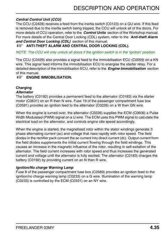
DESCRIPTION AND OPERATION
FREELANDER 03MY 4.35
Central Control Unit (CCU)The CCU (C0428) receives a feed from the inertia switch (C0123) on a GU wire. If this feed is removed due to the inertia switch being tripped, the CCU will unlock all of the doors. For more details of CCU operation, refer to the Control Units section of the Workshop manual. For more details of the Central Door Locking (CDL) system, refer to the Anti-theft Alarm and Central Door Locking (CDL) section of this manual. + ANTI-THEFT ALARM AND CENTRAL DOOR LOCKING (CDL).
NOTE: The CCU will only unlock all doors if the ignition switch is in the 'ignition' position.
The CCU (C0429) also provides a signal feed to the immobilisation ECU (C0059) on a KN wire. This signal feed informs the immobilisation ECU to energise the starter relay. For a detailed description of the immobilisation ECU, refer to the Engine Immobilisation section of this manual. + ENGINE IMMOBILISATION.
ChargingAlternatorThe battery (C0192) provides a permanent feed to the alternator (C0183) via the starter motor (C0631) on an R then N wire. Fuse 19 of the passenger compartment fuse box (C0581) provides an ignition feed to the alternator (C0226) on a W then GN wire.
When the engine is turned over, the alternator (C0226) supplies the ECM (C0606) a Pulse Width Modulated (PWM) signal on a U wire. The ECM uses this PWM signal to calculate the electrical load on the alternator, and controls engine idle speed accordingly.
When the engine is started, the magnetised rotor within the stator windings generate 3 phase alternating current (ac) and voltage that rises rapidly with rotor speed. The field diodes in the rectifier pack convert the ac current into direct current (dc). Output current from the field diodes supplements the initial current flowing through the field windings. This causes an increase in the magnetic influence of the rotor, resulting in self-exitation of the alternator. The field current increases with rotor speed and thus increases the generated current and voltage until the alternator is fully excited. The alternator (C0183) charges the battery (C0192) by providing current on an N then R wire.
Ignition/No charge Warning LampFuse 8 of the passenger compartment fuse box (C0589) provides an ignition feed to the ignition/no charge warning lamp (C0233) on a G wire. Illumination of the warning lamp (C0233) is controlled by the ECM (C0331) on an NY wire.

DESCRIPTION AND OPERATION
4.36 FREELANDER 03MY
CHARGING AND STARTING – K SERIES
DESCRIPTIONStartingThe starting system on the vehicle comprises a 12 volt starter motor which drives the engine to start the combustion process. The starter converts electrical energy into mechanical power. The vehicle electrical system must be capable of supplying sufficient power to enable the engine to be cranked.
ChargingThe charging system comprises a battery and an alternator. The battery must be of a sufficient capacity to operate the starter motor and operate various electrical systems in the vehicle. The alternator charges the battery when the engine is running and increases its output as demand on the battery increases.
The instrument pack incorporates a charge warning lamp which illuminates when there is no output or a low output from the alternator. For a detailed description of the charging and starting system, refer to the Engine Management Systems – MEMS section of the System Description and Operation Workshop manual.
OPERATIONGeneralFeed from the positive battery terminal (C0192) is supplied to fusible link 1, fusible link 3, fuse 10 and the main relay (C0632) on an R wire. All are located within the engine compartment fuse box. The battery (C0192) also provides a feed to the starter motor solenoid (C0178) on an R wire.
Fusible link 1 is connected in series with fusible link 7, which is also located within the engine compartment fuse box.
Fusible link 3 (C0571) is connected to the ignition switch (C0028) by an N wire. When the ignition switch is turned to the 'ignition' position, current flows across the switch (C0028) to fuse 6, fuse 8, and fuse 19 of the passenger compartment fuse box (C0588) on a G wire.
When the ignition switch is turned to the 'crank' position, current flows across the switch (C0028) to fuse 5 of the passenger compartment fuse box (C0588) on a WR wire.

DESCRIPTION AND OPERATION
FREELANDER 03MY 4.37
StartingMain RelayFuse 6 of the passenger compartment fuse box (C0581) provides an ignition feed to the Engine Control Module (ECM) (C0913) on a W wire. When the ECM receives this feed, it energises the main relay by providing an earth path for the relay coil (C0576) on a WK wire. The energised main relay is now able to provide a feed to the fuel pump relay. The fuel pump relay is also located in the engine compartment fuse box.
For a detailed description of main relay operation, refer to the Engine Management Systems – MEMS section of the System Description and Operation Workshop manual.
Inertia SwitchFuse 10 of the engine compartment fuse box (C0575) provides a constant battery feed to the inertia switch (C0123) on a G wire. The inertia switch is a normally closed switch. If the inertia switch hasn't been tripped, current flows across the switch (C0123) to the fuel pump relay (C0575) on a GU wire.
The inertia switch (C0123) also provides a feed to the Central Control Unit (CCU) (C0428) on a UG wire. For more information on the CCU, refer to the Control Units section of the Workshop manual, and the Anti-theft Alarm and Central Door Locking (CDL) section of this manual. + ANTI-THEFT ALARM AND CENTRAL DOOR LOCKING (CDL).
Fuel Pump RelayThe fuel pump relay coil receives a feed from the energised main relay (see above). The earth path for the relay coil (C0575) is controlled by the ECM (C0913) on a BP wire. The ECM will energise the fuel pump relay when it receives an ignition feed from fuse 6 of the passenger compartment fuse box (C0581) on a W wire.
The energised fuel pump relay (C0572) provides a feed to the fuel pump (C0114) on a WP wire. The pump (C0114) is earthed on a B wire.
Starter RelayFuse 5 of the passenger compartment fuse box (C0581) provides an ignition switch 'crank' feed to the immobilisation ECU (C0059) on a WR wire. If the vehicle has been successfully re-mobilised, the immobilisation ECU (C0059) provides a feed to the starter relay coil (C0576) on a RW wire. The starter relay is located in the engine compartment fuse box, and is earthed (C0576) on a B wire. A battery feed from fusible link 7 is now able to flow across the starter relay switch contacts (C0572) to the starter motor solenoid (C0179) on an NR wire.
For a detailed description of the immobilisation ECU, refer to the Engine Immobilisation section of this manual. + ENGINE IMMOBILISATION.

DESCRIPTION AND OPERATION
4.38 FREELANDER 03MY
Starter Motor and Starter Motor SolenoidThe starter motor solenoid coil (C0179) receives a feed from the energised starter motor relay (C0572) on an NR wire (see above). The energised starter motor solenoid allows a battery feed (C0178) to flow across the switch contacts and power the starter motor.
Central Control Unit (CCU)The CCU (C0428) receives a feed from the inertia switch (C0123) via the engine compartment fuse box (C0576) on a UG wire. If this feed is removed due to the inertia switch being tripped, the CCU will unlock all of the doors. For more details of the Central Door Locking (CDL) system, refer to the Anti-theft Alarm and Central Door Locking (CDL) section of this manual. + ANTI-THEFT ALARM AND CENTRAL DOOR LOCKING (CDL).
NOTE: The CCU will only unlock all doors if the ignition switch is in the 'ignition' position.
The CCU (C0429) also provides a signal feed to the immobilisation ECU (C0059) on a KN wire. This signal feed informs the immobilisation ECU to energise the starter relay. For a detailed description of the immobilisation ECU, refer to the Engine Immobilisation section of this manual. + ENGINE IMMOBILISATION.
ChargingAlternatorFusible link 1 of the engine compartment fuse box (C0826) provides a constant battery feed to the alternator (C0183) on an R wire. Fuse 19 of the passenger compartment fuse box (C0581) provides an ignition feed to the alternator (C0185) on a W wire.
When the engine is started, the magnetised rotor within the stator windings generate 3 phase alternating current (ac) and voltage that rises rapidly with rotor speed. The field diodes in the rectifier pack convert the ac current into direct current (dc). Output current from the field diodes supplements the initial current flowing through the field windings. This causes an increase in the magnetic influence of the rotor, resulting in self-exitation of the alternator. The field current increases with rotor speed and thus increases the generated current and voltage until the alternator is fully excited.
When the engine is running, the alternator (C0185) supplies the ECM (C0914) with a Pulse Width Modulated (PWM) signal on a WR wire. The ECM uses the PWM signal to calculate electrical load on the alternator, and controls idle speed accordingly.
The alternator (C0183) charges the battery by providing current via fusible link 1 of the engine compartment fuse box (C0826 & C0632) to the battery positive terminal (C0192) on an R wire.
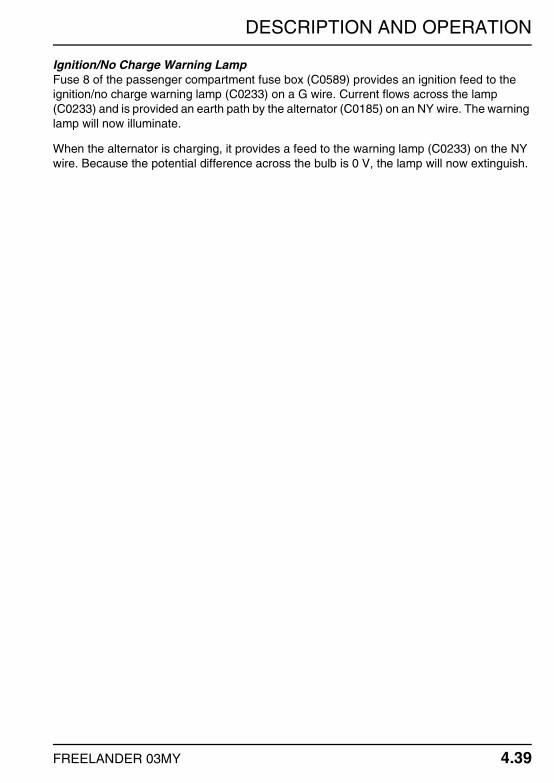
DESCRIPTION AND OPERATION
FREELANDER 03MY 4.39
Ignition/No Charge Warning LampFuse 8 of the passenger compartment fuse box (C0589) provides an ignition feed to the ignition/no charge warning lamp (C0233) on a G wire. Current flows across the lamp (C0233) and is provided an earth path by the alternator (C0185) on an NY wire. The warning lamp will now illuminate.
When the alternator is charging, it provides a feed to the warning lamp (C0233) on the NY wire. Because the potential difference across the bulb is 0 V, the lamp will now extinguish.

DESCRIPTION AND OPERATION
4.40 FREELANDER 03MY
CHARGING AND STARTING – KV6
DESCRIPTIONStartingThe starting system on the vehicle comprises a 12 volt starter motor which drives the engine to start the combustion process. The starter converts electrical energy into mechanical power. The vehicle electrical system must be capable of supplying sufficient power to enable the engine to be cranked.
ChargingThe charging system comprises a battery and an alternator. The battery must be of a sufficient capacity to operate the starter motor and operate various electrical systems in the vehicle. The alternator charges the battery when the engine is running and increases its output as demand on the battery increases.
The instrument pack incorporates a charge warning lamp which illuminates when there is no output or a low output from the alternator. For a detailed description of the charging and starting system, refer to the Engine Management Systems – Siemens (All Except NAS) section of the System Description and Operation Workshop manual.
OPERATIONGeneralFeed from the positive battery terminal (C0192) is supplied to fusible link 1, fusible link 3, fuse 10, and the main relay (C0632) on an R wire. All are located in the engine compartment fuse box. The battery (C0192) also provides a feed to the starter motor solenoid (C0178) on an R wire.
Fusible link 1 is connected in series with fusible link 7, which is also located in the engine compartment fuse box.
Fusible link 3 (C0571) is connected to the ignition switch (C0028) by an N wire. When the ignition switch is turned to the 'ignition' position, current flows across the switch (C0028) to fuse 6, fuse 8, and fuse 19 of the passenger compartment fuse box (C0588) on a G wire.
When the ignition switch is turned to the 'crank' position, current flows across the switch (C0028) to fuse 5 of the passenger compartment fuse box (C0588) on a WR wire.
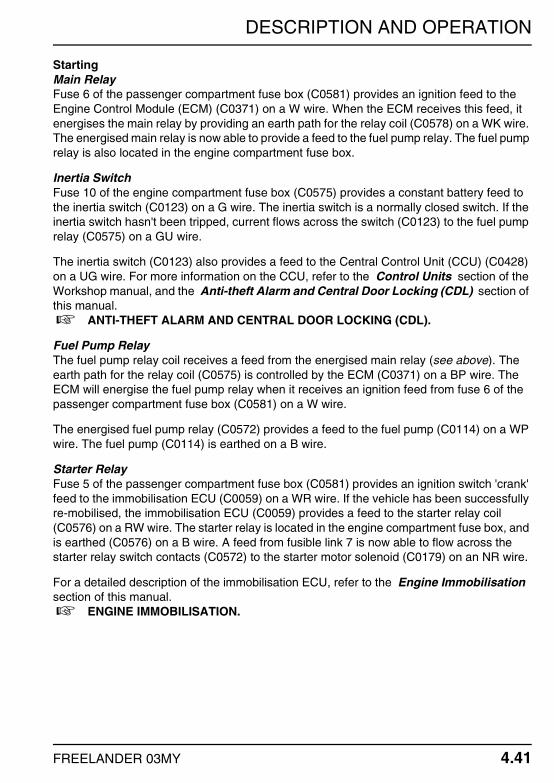
DESCRIPTION AND OPERATION
FREELANDER 03MY 4.41
StartingMain RelayFuse 6 of the passenger compartment fuse box (C0581) provides an ignition feed to the Engine Control Module (ECM) (C0371) on a W wire. When the ECM receives this feed, it energises the main relay by providing an earth path for the relay coil (C0578) on a WK wire. The energised main relay is now able to provide a feed to the fuel pump relay. The fuel pump relay is also located in the engine compartment fuse box.
Inertia SwitchFuse 10 of the engine compartment fuse box (C0575) provides a constant battery feed to the inertia switch (C0123) on a G wire. The inertia switch is a normally closed switch. If the inertia switch hasn't been tripped, current flows across the switch (C0123) to the fuel pump relay (C0575) on a GU wire.
The inertia switch (C0123) also provides a feed to the Central Control Unit (CCU) (C0428) on a UG wire. For more information on the CCU, refer to the Control Units section of the Workshop manual, and the Anti-theft Alarm and Central Door Locking (CDL) section of this manual. + ANTI-THEFT ALARM AND CENTRAL DOOR LOCKING (CDL).
Fuel Pump RelayThe fuel pump relay coil receives a feed from the energised main relay (see above). The earth path for the relay coil (C0575) is controlled by the ECM (C0371) on a BP wire. The ECM will energise the fuel pump relay when it receives an ignition feed from fuse 6 of the passenger compartment fuse box (C0581) on a W wire.
The energised fuel pump relay (C0572) provides a feed to the fuel pump (C0114) on a WP wire. The fuel pump (C0114) is earthed on a B wire.
Starter RelayFuse 5 of the passenger compartment fuse box (C0581) provides an ignition switch 'crank' feed to the immobilisation ECU (C0059) on a WR wire. If the vehicle has been successfully re-mobilised, the immobilisation ECU (C0059) provides a feed to the starter relay coil (C0576) on a RW wire. The starter relay is located in the engine compartment fuse box, and is earthed (C0576) on a B wire. A feed from fusible link 7 is now able to flow across the starter relay switch contacts (C0572) to the starter motor solenoid (C0179) on an NR wire.
For a detailed description of the immobilisation ECU, refer to the Engine Immobilisation section of this manual. + ENGINE IMMOBILISATION.

DESCRIPTION AND OPERATION
4.42 FREELANDER 03MY
Starter Motor and Starter Motor SolenoidThe starter motor solenoid coil (C0179) receives a feed from the energised starter relay (C0572) on an NR wire (see above). The energised starter motor solenoid allows a battery feed (C0178) to flow across the switch contacts and power the starter motor.
Central Control Unit (CCU)The CCU (C0428) receives a feed from the inertia switch (C0123) via the engine compartment fuse box (C0576) on a UG wire. If this feed is removed due to the inertia switch being tripped, the CCU will unlock all of the doors. For more details of the Central Door Locking (CDL) system, refer to the Anti-theft Alarm and Central Door Locking (CDL) section of this manual. + ANTI-THEFT ALARM AND CENTRAL DOOR LOCKING (CDL).
NOTE: The CCU will only unlock all doors if the ignition switch is in the 'ignition' position.
The CCU (C0429) also provides a signal feed to the immobilisation ECU (C0059) on a KN wire. This signal feed informs the immobilisation ECU to energise the starter relay. For a detailed description of the immobilisation ECU, refer to the Engine Immobilisation section of this manual. + ENGINE IMMOBILISATION.
ChargingAlternatorFusible link 1 of the engine compartment fuse box (C0826) provides a constant battery feed to the alternator (C0183) on an R wire. Fuse 19 of the passenger compartment fuse box (C0581) provides an ignition feed to the alternator (C0053) on a W wire.
When the engine is turned over, the alternator (C0053) supplies the ECM (C0371) with a Pulse Width Modulated (PWM) signal on a GK wire. The ECM uses this PWM signal to calculate the electrical load on the alternator, and controls engine idle speed accordingly.
When the engine is started, the magnetised rotor within the stator windings generate 3 phase alternating current (ac) and voltage that rises rapidly with rotor speed. The field diodes in the rectifier pack convert the ac current into direct current (dc). Output current from the field diodes supplements the initial current flowing through the field windings. This causes an increase in the magnetic influence of the rotor, resulting in self-exitation of the alternator. The field current increases with rotor speed and thus increases the generated current and voltage until the alternator is fully excited.
The alternator (C0183) charges the battery by providing current via fusible link 1 of the engine compartment fuse box (C0826 & C0632) to the battery positive terminal (C0192) on an R wire.

DESCRIPTION AND OPERATION
FREELANDER 03MY 4.43
Ignition/No Charge Warning LampFuse 8 of the passenger compartment fuse box (C0589) provides an ignition feed to the ignition/no charge warning lamp (C0233) on a G wire. Current flows across the lamp (C0233) and is provided an earth path by the alternator (C0053) on an NY wire. The warning lamp will now illuminate.
When the alternator is charging, it provides a feed to the warning lamp (C0233) on the NY wire. Because the potential difference across the bulb is 0 V, the lamp will now extinguish.

DESCRIPTION AND OPERATION
4.44 FREELANDER 03MY
CHARGING AND STARTING – KV6 (NORTH AMERICA)
DESCRIPTIONStartingThe starting system on the vehicle comprises a 12 volt starter motor which drives the engine to start the combustion process. The starter converts electrical energy into mechanical power. The vehicle electrical system must be capable of supplying sufficient power to enable the engine to be cranked.
ChargingThe charging system comprises a battery and an alternator. The battery must be of a sufficient capacity to operate the starter motor and operate various electrical systems in the vehicle. The alternator charges the battery when the engine is running and increases its output as demand on the battery increases.
The instrument pack incorporates a charge warning lamp which illuminates when there is no output or a low output from the alternator. For a detailed description of the charging and starting system, refer to the Engine Management Systems – Siemens (NAS) section of the System Description and Operation Workshop manual.
OPERATIONGeneralFeed from the positive battery terminal (C0192) is supplied to fusible link 1, fusible link 3, fuse 10, and the main relay (C0632) on an R wire. All are located in the engine compartment fuse box. The battery (C0192) also provides a feed to the starter motor solenoid (C0178) on an R wire.
Fusible link 1 is connected in series with fusible link 7, which is also located in the engine compartment fuse box.
Fusible link 3 (C0571) is connected to the ignition switch (C0028) by an N wire. When the ignition switch is turned to the 'ignition' position, current flows across the switch (C0028) to fuse 6, fuse 8, and fuse 19 of the passenger compartment fuse box (C0588) on a G wire.
When the ignition switch is turned to the 'crank' position, current flows across the switch (C0028) to fuse 5 of the passenger compartment fuse box (C0588) on a WR wire.

DESCRIPTION AND OPERATION
FREELANDER 03MY 4.45
StartingMain RelayFuse 6 of the passenger compartment fuse box (C0581) provides an ignition feed to the Engine Control Module (ECM) (C0603) on a W wire. When the ECM receives this feed, it energises the main relay by providing an earth path for the relay coil (C0578) on an NG wire. The energised main relay is now able to provide a feed to the fuel pump relay. The fuel pump relay is also located in the engine compartment fuse box.
Inertia SwitchFuse 10 of the engine compartment fuse box (C0575) provides a constant battery feed to the inertia switch (C0123) on a G wire. The inertia switch is a normally closed switch. If the inertia switch hasn't been tripped, current flows across the switch (C0123) to the fuel pump relay (C0575) on a GU wire.
The inertia switch (C0123) also provides a feed to the Central Control Unit (CCU) (C0428) on a UG wire. For more information on the CCU, refer to the Control Units section of the Workshop manual, and the Anti-theft Alarm and Central Door Locking (CDL) section of this manual. + ANTI-THEFT ALARM AND CENTRAL DOOR LOCKING (CDL).
Fuel Pump RelayThe fuel pump relay coil receives a feed from the energised main relay (see above). The earth path for the relay coil (C0575) is controlled by the ECM (C0331) on a BP wire. The ECM will energise the fuel pump relay when it receives an ignition feed from fuse 6 of the passenger compartment fuse box (C0581) on a W wire.
The energised fuel pump relay (C0572) provides a feed to the fuel pump (C0114) on a WP wire. The fuel pump (C0114) is earthed on a B wire.
Starter RelayFuse 5 of the passenger compartment fuse box (C0581) provides an ignition switch 'crank' feed to the immobilisation ECU (C0059) on a WR wire. If the vehicle has been successfully re-mobilised, the immobilisation ECU (C0059) provides a feed to the starter relay coil (C0576) on a RW wire. The starter relay is located in the engine compartment fuse box, and is earthed (C0576) on a B wire. A feed from fusible link 7 is now able to flow across the starter relay switch contacts (C0572) to the starter motor solenoid (C0179) on an NR wire.
For a detailed description of the immobilisation ECU, refer to the Engine Immobilisation section of this manual. + ENGINE IMMOBILISATION.

DESCRIPTION AND OPERATION
4.46 FREELANDER 03MY
Starter Motor and Starter Motor SolenoidThe starter motor solenoid coil (C0179) receives a feed from the energised starter relay (C0572) on an NR wire (see above). The energised starter motor solenoid allows a battery feed (C0178) to flow across the switch contacts and power the starter motor.
Central Control Unit (CCU)The CCU (C0428) receives a feed from the inertia switch (C0123) via the engine compartment fuse box (C0576) on a UG wire. If this feed is removed due to the inertia switch being tripped, the CCU will unlock all of the doors. For more details of the Central Door Locking (CDL) system, refer to the Anti-theft Alarm and Central Door Locking (CDL) section of this manual. + ANTI-THEFT ALARM AND CENTRAL DOOR LOCKING (CDL).
NOTE: The CCU will only unlock all doors if the ignition switch is in the 'ignition' position.
The CCU (C0429) also provides a signal feed to the immobilisation ECU (C0059) on a KN wire. This signal feed informs the immobilisation ECU to energise the starter relay. For a detailed description of the immobilisation ECU, refer to the Engine Immobilisation section of this manual. + ENGINE IMMOBILISATION.
ChargingAlternatorFusible link 1 of the engine compartment fuse box (C0826) provides a constant battery feed to the alternator (C0183) on an R wire. Fuse 19 of the passenger compartment fuse box (C0581) provides an ignition feed to the alternator (C0053) on a W wire.
When the engine is turned over, the alternator (C0053) supplies the ECM (C0331) with a Pulse Width Modulated (PWM) signal on a GK wire. The ECM uses this PWM signal to calculate the electrical load on the alternator, and controls engine idle speed accordingly.
When the engine is started, the magnetised rotor within the stator windings generate 3 phase alternating current (ac) and voltage that rises rapidly with rotor speed. The field diodes in the rectifier pack convert the ac current into direct current (dc). Output current from the field diodes supplements the initial current flowing through the field windings. This causes an increase in the magnetic influence of the rotor, resulting in self-exitation of the alternator. The field current increases with rotor speed and thus increases the generated current and voltage until the alternator is fully excited.
The alternator (C0183) charges the battery by providing current via fusible link 1 of the engine compartment fuse box (C0826 & C0632) to the battery positive terminal (C0192) on an R wire.

DESCRIPTION AND OPERATION
FREELANDER 03MY 4.47
Ignition/No Charge Warning LampFuse 8 of the passenger compartment fuse box (C0589) provides an ignition feed to the ignition/no charge warning lamp (C0233) on a G wire. Current flows across the lamp (C0233) and is provided an earth path by the alternator (C0053) on an NY wire. The warning lamp will now illuminate.
When the alternator is charging, it provides a feed to the warning lamp (C0233) on the NY wire. Because the potential difference across the bulb is 0 V, the lamp will now extinguish.

DESCRIPTION AND OPERATION
4.48 FREELANDER 03MY
CRUISE CONTROL – TD4 & KV6 (NORTH AMERICA)
DESCRIPTIONGeneralCruise control is switched on by pressing the cruise control master switch mounted on the centre console. The 'Set +' and 'Res' switches mounted on the steering wheel allow the driver to either set the vehicle speed as required or resume the last cruising speed set.
The cruise control system uses mechanical, electrical and vacuum operated devices to maintain vehicle speed at a setting selected by the driver. As vehicle speed changes due to changes in road gradients, so the cruise control ECU operates the cruise control pump, continually moving the cruise control actuator to maintain the set vehicle speed.
Should the driver wish to increase the speed of the vehicle, the 'Set +' switch should be pressed and held. The vehicle will accelerate until the switch is released. As the 'Set +' switch is released, the cruise control ECU will store the new cruise speed in its memory.
With cruise control switched on, it is possible to press the accelerator pedal and accelerate through the memorised set speed. When the accelerator is released, the cruise control ECU will automatically return the vehicle to its set speed.
Note: The cruise control system will only operate between speeds of 22 mph (35 kph) and 125 mph (201 kph).
Cruise control operation can be suspended by one of the following ways:
By pressing the 'Res' switch.By pressing the brake pedal.The gearbox is placed in park, neutral, or reverse.Hill Descent Control (HDC) is active.Engine rev's are too high.
Under all these conditions, the cruise control set speed will be memorised. Cruise control operation can be resumed by pressing the 'Res' switch.
Cruise control operation can be cancelled in one of two ways:
By pressing the cruise control master switch located on the centre console.By switching the ignition off.
In both these cases, the cruise control set speed will be lost.
Warning: Do not switch off the vehicle ignition unless the vehicle is stationary and the handbrake is applied.

DESCRIPTION AND OPERATION
FREELANDER 03MY 4.49
OPERATIONGeneralFeed from the positive battery terminal (C0192) is supplied to the main relay, the horn relay, and fusible link 3 (C0632) on an R wire. All are located in the engine compartment fuse box.
The earth path for the main relay (C0578) is controlled by the ECM (C0604) on an NG wire. The energised main relay provides a feed to fuse 4, which is also located in the engine compartment fuse box. For more information on main relay operation, refer to the Engine Management System – EDC or Engine Management System – Siemens (NAS) section of the System Description and Operation Workshop manual.
Fusible link 3 (C0571) is connected to the ignition switch (C0028) by an N wire. When the ignition switch is turned to the 'ignition' position, current flows across the switch (C0028) to fuse 35 of the passenger compartment fuse box (C0588) on a G wire.
Cruise Control Master SwitchCruise control is switched on and off by pressing the master switch mounted on the centre console. Fuse 35 of the passenger compartment fuse box (C0580) supplies the cruise control master switch (C0749) an ignition feed on a W wire. When the switch is pressed, current flows across the switch contacts (C0749) to the cruise control interface unit (C1959) on a WY wire.
NOTE: When the cruise control system is switched off using the master switch, any stored road speed values will be lost.
Cruise Control Interface UnitFuse 4 of the engine compartment fuse box (C0575) provides a feed to the cruise control interface unit (C1959) on an NK wire. The interface unit (C1959) is earthed on a B wire. To enable it to control the cruise control system, the ECU receives a number of inputs from various sources as follows:
ABS ECUThe ABS ECU (C0501) provides a road speed signal to the cruise control interface unit (C1959) via the CAN-BUS on YN (Low) and YB (High) wires. For more information on the CAN-BUS road speed signal, refer to the Communication Databuses section of the System Description and Operation Workshop manual.
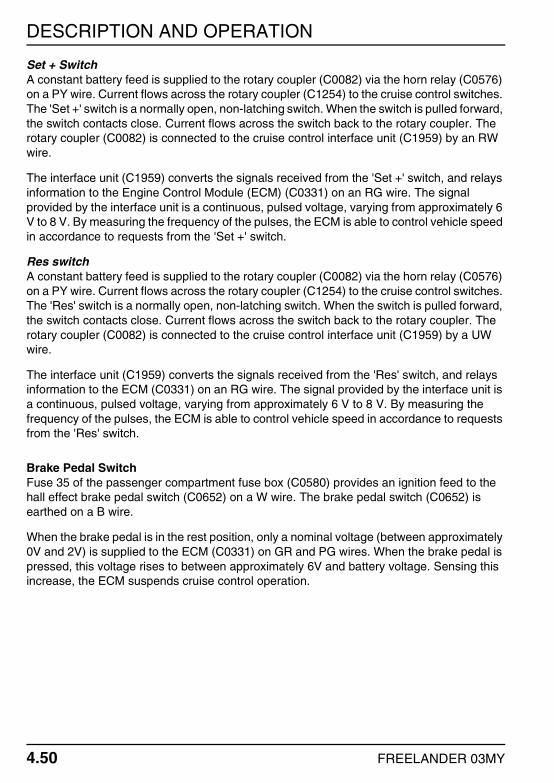
DESCRIPTION AND OPERATION
4.50 FREELANDER 03MY
Set + SwitchA constant battery feed is supplied to the rotary coupler (C0082) via the horn relay (C0576) on a PY wire. Current flows across the rotary coupler (C1254) to the cruise control switches. The 'Set +' switch is a normally open, non-latching switch. When the switch is pulled forward, the switch contacts close. Current flows across the switch back to the rotary coupler. The rotary coupler (C0082) is connected to the cruise control interface unit (C1959) by an RW wire.
The interface unit (C1959) converts the signals received from the 'Set +' switch, and relays information to the Engine Control Module (ECM) (C0331) on an RG wire. The signal provided by the interface unit is a continuous, pulsed voltage, varying from approximately 6 V to 8 V. By measuring the frequency of the pulses, the ECM is able to control vehicle speed in accordance to requests from the 'Set +' switch.
Res switchA constant battery feed is supplied to the rotary coupler (C0082) via the horn relay (C0576) on a PY wire. Current flows across the rotary coupler (C1254) to the cruise control switches. The 'Res' switch is a normally open, non-latching switch. When the switch is pulled forward, the switch contacts close. Current flows across the switch back to the rotary coupler. The rotary coupler (C0082) is connected to the cruise control interface unit (C1959) by a UW wire.
The interface unit (C1959) converts the signals received from the 'Res' switch, and relays information to the ECM (C0331) on an RG wire. The signal provided by the interface unit is a continuous, pulsed voltage, varying from approximately 6 V to 8 V. By measuring the frequency of the pulses, the ECM is able to control vehicle speed in accordance to requests from the 'Res' switch.
Brake Pedal SwitchFuse 35 of the passenger compartment fuse box (C0580) provides an ignition feed to the hall effect brake pedal switch (C0652) on a W wire. The brake pedal switch (C0652) is earthed on a B wire.
When the brake pedal is in the rest position, only a nominal voltage (between approximately 0V and 2V) is supplied to the ECM (C0331) on GR and PG wires. When the brake pedal is pressed, this voltage rises to between approximately 6V and battery voltage. Sensing this increase, the ECM suspends cruise control operation.

DESCRIPTION AND OPERATION
FREELANDER 03MY 4.51
Electronic Automatic Transmission (EAT) ECUWhen cruise control is active, the cruise control interface unit (C1959) provides a feed to the EAT ECU (C0932) on a WU wire. When the EAT ECU receives this feed, it enters its cruise control mode. For more information on EAT operation, refer to the Electronic Automatic Transmission (EAT) section of this manual. + ELECTRONIC AUTOMATIC TRANSMISSION (EAT).
Instrument PackWhen cruise control is operational, the cruise control interface unit (C1959) sends a 'cruise active' message to the instrument pack (C0230) via the CAN-BUS on YN (low) and YB (high) wires. This message is used to illuminate the cruise control lamp housed within the instrument pack.

DESCRIPTION AND OPERATION
4.52 FREELANDER 03MY
CRUISE CONTROL – KV6
DESCRIPTIONGeneralCruise control is switched on by pressing the cruise control master switch mounted on the centre console. The 'Set +' and 'Res' switches mounted on the steering wheel allow the driver to either set the vehicle speed as required or resume the last cruising speed set.
The cruise control system uses mechanical, electrical and vacuum operated devices to maintain vehicle speed at a setting selected by the driver. As vehicle speed changes due to changes in road gradients, so the cruise control ECU operates the cruise control pump, continually moving the cruise control actuator to maintain the set vehicle speed.
Should the driver wish to increase the speed of the vehicle, the 'Set +' switch should be pressed and held. The vehicle will accelerate until the switch is released. As the 'Set +' switch is released, the cruise control ECU will store the new cruise speed in its memory.
With cruise control switched on, it is possible to press the accelerator pedal and accelerate through the memorised set speed. When the accelerator is released, the cruise control ECU will automatically return the vehicle to its set speed.
Note: The cruise control system will only operate between speeds of 22 mph (35 km/h) and 125 mph (200 km/h).
Cruise control operation can be suspended by one of the following ways:
By pressing the 'Res' switch.By pressing the brake pedal.The gearbox is placed in park, neutral, or reverse.Hill Descent Control (HDC) is active.Engine rev's are too high.
Under all these conditions, the cruise control set speed will be memorised. Cruise control operation can be resumed by pressing the 'Res' switch.
Cruise control operation can be cancelled in one of two ways:
By pressing the cruise control master switch located on the centre console.By switching the ignition off.
In both these cases, the cruise control set speed will be lost.
Warning: Do not switch off the vehicle ignition unless the vehicle is stationary and the handbrake is applied.
DESCRIPTION AND OPERATION
FREELANDER 03MY 4.53
OPERATIONGeneralFeed from the positive battery terminal (C0192) is supplied to the horn relay and fusible link 3 of the engine compartment fuse box (C0632) on an R wire. Fusible link 3 (C0571) is connected to the ignition switch (C0028) by an N wire. When the ignition switch is turned to the 'ignition' position, current flows across the switch (C0028) to fuse 35 of the passenger compartment fuse box (C0588) on a G wire. Fuse 35 (C0580) provides an ignition feed to the following:
The cruise control master switch (C0749) on a W then WK wire.The cruise control interface unit (C1959) on a W wire (via header 292).The brake pedal sensor (C0652) on a W wire (via header 292).
The ignition switch (C0028) also provides a feed to fuse 2 of the passenger compartment fuse box (C0588) on an NW wire. Fuse 2 (C0580) provides an ignition feed to the brake pedal switch (C0075) on a G wire.
Cruise Control Master SwitchThe cruise control master switch (C0749) is mounted in the centre console and is provided an ignition feed from fuse 35 of the passenger compartment fuse box (C0580) on a W then WK wire. When the switch is pressed, current flows across the switch contacts (C0749) to the cruise control interface unit (C1959) and the cruise control ECU (C0239) on WY wires.
NOTE: When the cruise control system is switched off using the master switch, any stored road speed values will be lost.
Cruise Control ECUWhen cruise control is activated, the cruise control ECU (C0239) receives a feed from the cruise control master switch (C0749) on a WY wire. The ECU (C0239) is earthed on a B wire. To enable it to control the cruise control system, the ECU receives a number of inputs from various sources as follows:

DESCRIPTION AND OPERATION
4.54 FREELANDER 03MY
ABS ECU The ABS ECU (C0501) provides a pulsed wheel speed signal to the cruise control ECU (C0239) on a WO wire. The rate of pulses provided by the ABS ECU increases by 2.22 Hz for every mile per hour speed increase (approximately 8,000 pulses per mile travelled). This enables the cruise control ECU to calculate the road speed of the vehicle. If vehicle speed is outside the operating limits (see Description), the cruise control ECU will not activate the system.
NOTE: If the Cruise Control ECU fails to receive a pulsed wheel speed signal from the ABS modulator, cruise control will not operate.
For more information on ABS ECU operation, refer to the Anti-lock Braking System (ABS) section of this manual. + ANTI-LOCK BRAKING SYSTEM (ABS).
Set + SwitchThe non latching Set + switch (C1254) is provided a feed via the horn relay (C0576) on a PY wire. When the switch is pulled back against spring pressure, the switch contacts close and a feed is provided to the cruise control ECU (C0239) via the rotary coupler (C0082) on a RW wire.
If cruise control is active, and the switch is operated for the first time, the cruise control ECU will store the current vehicle speed in its memory and maintain that speed.
NOTE: The cruise control ECU will only store and maintain the vehicle speed if it is within the operating limits given in the 'Description' section above.
If the switch is tapped a second time, the ECU will increase the vehicle speed by 1 mph. If the switch is pulled back and held against spring pressure, the vehicle will accelerate until the switch is released. The final vehicle speed in both instances will be stored in the cruise control ECU memory.
Res SwitchThe non latching Res switch (C1254) is provided a feed via the horn relay (C0576) on a PY wire. When the switch is pulled back against spring pressure, the switch contacts close and a feed is provided to the cruise control ECU (C0239) via the rotary coupler (C0082) on a UW wire.
If the Res switch is pulled back against spring pressure, the cruise control ECU will alter vehicle speed to reflect the vehicle speed held within its memory. If the Res switch is pulled back for a second time, cruise control operation will be suspended
NOTE: If a road speed value is not held within the cruise control ECU memory, the ECU will not respond to the Res switch input. To enter a vehicle speed into the ECU memory, refer to the 'Set + Switch' section above.

DESCRIPTION AND OPERATION
FREELANDER 03MY 4.55
Brake Pedal SensorThe Hall effect brake pedal sensor (C0652) is provided an ignition feed from fuse 35 of the passenger compartment fuse box (C0580) on a W wire. The sensor (C0652) is earthed on a B wire. When the brake pedal is in its normal position, the sensor provides the cruise control interface unit (C1959) a low voltage (between approximately 0V and 2V) on a PG wire. When the brake pedal is pressed, this voltage rises to between approximately 6V and battery voltage. When the interface unit registers this rise in voltage, it suspends cruise control operation.
The brake pedal sensor (C0652) also provides a brake pedal status signal to the cruise control interface unit (C1959) on a GR wire.
Interface UnitThe interface unit (C1959) provides a feed to the cruise control ECU (C0239) on a PG wire if the following conditions exist:
The cruise control master switch is depressed.The brake pedal is not depressed.HDC is not activated.The gear selector lever is not in the park, neutral, or reverse positions.Engine speed is below 6,496 rpm.
The cruise control ECU uses the feed provided by the interface unit to enable the cruise control pump. For more details on interface unit operation, refer to the Interface Unit section below.
Interface UnitFuse 35 of the passenger compartment fuse box (C0580) provides an ignition feed to the interface unit (C1959) on a W wire. The interface unit is earthed on a pair of B wires, and receives inputs from a number of different components as follows:
Cruise Control Master SwitchWhen the cruise control master switch is depressed, it provides a feed to the interface unit (C1959) on a WY wire.
Brake Pedal SensorWhen the brake pedal is in its normal position, the sensor (C0652) provides the interface unit (C1959) a low voltage (between approximately 0V and 2V) on GR and PG wires. When the brake pedal is pressed, this voltage rises to between approximately 6V and battery voltage.

DESCRIPTION AND OPERATION
4.56 FREELANDER 03MY
Engine Control Module (ECM)The ECM (C0371) provides a feed to the interface unit (C1959) on a BU wire if the following conditions exist:
HDC is not activated.The gear selector lever is not in the park, neutral, or reverse positions.Engine speed is below 6,496 rpm.
For more information on the Siemens ECM, refer to the Engine Management Systems – Siemens section of the System Description and Operation Workshop manual.
Cruise Control PumpWhen all conditions for cruise control activation have been met, the cruise control ECU (C0239) provides a feed to the cruise control pump motor (C0228) on a WU wire. The pump motor creates a vacuum in the pump actuator. For a detailed description of actuator operation, refer to the Engine Management Systems – Siemens section of the Workshop manual.
Current flow across the pump motor is controlled by the ECU (C0239) providing a varying Pulse Width Modulated (PWM) signal to the other side of the pump motor (C0228) on a BR wire. When the correct vehicle speed has been reached, the ECU (C0239) replaces the PWM feed with a continuous feed. As the potential difference across the pump motor is now 0V, the pump motor stops operating.
To maintain the vacuum in the actuator, both the control and dump valves are closed by the ECU. To close the valves, the ECU (C0239) provides a feed to the control and dump valves (C0228) on a WU wire. Current flows across the control valve (C0228) to the ECU (C0239) on a PY wire. Current flows across the dump valve (C0228) to the ECU (C0239) on a BR wire.
NOTE: Both the control valve and the dump valve are normally open valves.
When a decrease in speed is requested, the control valve is opened to reduce the depression within the actuator. This is done by the ECU (C0239) providing a PWM signal to the control valve (C0228) on a PY wire. When the correct speed has been achieved, the PWM signal is withdrawn.
When cruise is cancelled, the ECU (C0239) withdraws the feed to the dump valve (C0228) on a WU wire. The dump valve now opens, allowing atmospheric pressure into the actuator.

DESCRIPTION AND OPERATION
FREELANDER 03MY 4.57
Brake Pedal SwitchAs a safety feature, the dump valve is opened if the brake pedal is depressed. If cruise control is active and the brake pedal is pressed, the brake pedal switch (C0075) provides a feed to the dump valve (C0228) on a GP wire. As the potential difference across the valve is 0V, the valve opens allowing atmospheric pressure into the actuator.
Electronic Automatic Transmission (EAT) ECUWhen all conditions for cruise control activation have been met, the cruise control ECU (C0239) provides a feed to the EAT ECU (C0932) on a WU wire. When the EAT ECU receives this feed, it enters its cruise control mode. For more information on EAT operation refer to the Electronic Automatic Transmission (EAT) section of this manual. + ELECTRONIC AUTOMATIC TRANSMISSION (EAT).
Instrument PackWhen all conditions for cruise control activation have been met, the cruise control ECU (C0239) provides a feed to the cruise control LED mounted within the instrument pack (C0230) on a WU wire. The cruise control LED is provided an earth by the instrument pack (C0230) on a B wire.
Diagnostic SocketThe diagnostic socket (C0040) is connected to the cruise control ECU (C0239) by a K wire, enabling the ECU to be interrogated by TestBook or T4.

DESCRIPTION AND OPERATION
4.58 FREELANDER 03MY
ELECTRONIC AUTOMATIC TRANSMISSION (EAT)
DESCRIPTIONGeneralThe Jatco 5–speed automatic transmission fitted to Freelander is controlled by an Electronic Automatic Transmission Electronic Control Unit (EAT ECU). The EAT ECU is located inside the engine E-box, and receives information from the following sources to calculate when to operate the solenoid valves contained within the gearbox to enable quick, smooth, quiet gear changes;
The Engine Control Module (ECM) via the CAN-BUS,The instrument pack via the CAN-BUS,The cruise control ECU,The automatic transmission selector,The brake pedal switch,The automatic gearbox sensors.
The Jatco automatic gearbox also has a number of different operating modes. When the ignition switch is first turned to the 'ignition' position, the gearbox will always revert to the 'Normal' mode. For a full description of the 5–speed automatic transmission, refer to the Automatic Gearbox – Jatco section of the System Description and Operation Workshop manual.
OPERATIONGeneralFeed from the positive battery terminal (C0192) is supplied to the main relay and fusible link 3 (C0632) on an R wire. Both are located in the engine compartment fuse box.
The battery also provides a feed to fusible link 4 of the engine compartment fuse box (C0632) on vehicles fitted with an instrument dimmer switch. For more information, refer to the Interior Lamps section of this manual. + INTERIOR LAMPS.

DESCRIPTION AND OPERATION
FREELANDER 03MY 4.59
Operation of the main relay (C0576 on Td4 vehicles, C0578 on KV6 vehicles) is controlled by the Engine Control Module (ECM) (C0603 on Td4 vehicles, C0604 on KV6 NAS vehicles, C0371 on KV6 ROW vehicles) on a WK wire (NG on KV6 NAS vehicles). The energised main relay allows a battery feed to flow to fuse 4 of the engine compartment fuse box. Fuse 4 (C0575) provides a feed to the following:
The Electronic Automatic Transmission Electronic Control Unit (EAT ECU) (C0932) on a NK wire.The transmission selector (C0244) (vehicles without instrument dimmer only) on a NK then a NR wire.The illumination relay (C1976) (vehicles with instrument dimmer only) on a NK then a NR wire.The CommandShift switch (C0410) on a NK wire.
For further details of main relay operation, refer to the Engine Management – EDC , Engine Management – Siemens (NAS) or Engine Management – Siemens (All Except NAS) section of the System Description and Operation Workshop manual.
Fusible link 3 (C0571) is connected to the ignition switch (C0028) by an N wire. When the ignition switch is turned to the 'ignition' position, current flows across the switch (C0028) to fuse 35 of the passenger compartment fuse box (C0588) on a G wire. Fuse 35 (C0580) provides an ignition feed to the transmission inhibit switch (C0244) on a W wire.

DESCRIPTION AND OPERATION
4.60 FREELANDER 03MY
EAT ECUThe EAT ECU monitors the operation of the automatic gearbox via four sensors:
The temperature of the automatic transmission fluid (ATF) is measured by the fluid temperature sensor. The fluid temperature sensor (C0243) receives a feed from the EAT ECU (C0932) on a WK wire. The temperature sensor return (C0243) to the EAT ECU (C0932) is via a KB wire. As the temperature of the ATF rises, so the resistance of the sensor decreases. The EAT ECU registers this drop in resistance and calculates the temperature of the ATF accordingly. For more information on the fluid temperature sensor, refer to the Automatic Gearbox – Jatco section of the System Description and Operation Workshop manual.Vehicle speed is measured by the vehicle speed sensor. The vehicle speed sensor (C0243) is connected to the EAT ECU (C0932) by a U wire. The speed sensor creates a sinusoidal waveform, with each positive phase of the waveform representing one tooth on the parking gear (19 per engine revolution). The EAT ECU uses this waveform to calculate vehicle speed. The sensor return (C0243) to the EAT ECU (C0932) is via a W then KB wire. For more information on the vehicle speed sensor, refer to the Automatic Gearbox – Jatco section of the System Description and Operation Workshop manual.Input shaft speed into the gearbox is measured by the turbine sensor. The turbine sensor (C0243) is connected to the EAT ECU (C0932) by an R wire. The turbine sensor creates a sinusoidal waveform, with 16 positive phases representing one input shaft revolution. The EAT ECU uses this signal along with a vehicle speed signal to calculate if the correct gear has been selected. The sensor return (C0243) to the EAT ECU (C0932) is via a U then KB wire. For more information on the turbine sensor, refer to the Automatic Gearbox – Jatco section of the System Description and Operation Workshop manual.The internal, or intermediate, transmission speed is measured by the intermediate sensor. The intermediate sensor (C0243) is connected to the EAT ECU (C0932) by an R wire. The intermediate sensor creates a sinusoidal waveform, with each positive phase of the waveform representing one tooth of the output gear (49 per revolution). The EAT ECU uses this signal to ensure the correct gear is engaged, and to monitor the amount of slip within the gearbox. The sensor return (C0243) to the EAT ECU (C0932) is via a B then KB wire. For more information on the intermediate sensor, refer to the Automatic Gearbox – Jatco section of the System Description and Operation Workshop manual.

DESCRIPTION AND OPERATION
FREELANDER 03MY 4.61
ParkWhen park is selected, a main relay feed is able to flow from the transmission selector/inhibit switch (C0244) to the EAT ECU (C0932) and the selector indicator (C0675) on a KO wire. The 'P' symbol on the selector housing will now illuminate.
NOTE: On Canadian specification vehicles, a feed is also provided to the Central Control Unit (CCU) (C0593) on a KO wire. This input is used by the CCU to extinguish the daylight running lamps.
ReverseWhen reverse gear is selected, a main relay feed is able to flow from the transmission selector/inhibit switch (C0244) to the reverse lamp relay (C0935) on an NG wire. The reverse lamp relay (C0935) is earthed on a B wire and controls operation of the reverse lamps. For more information on reverse lamp operation, refer to the Brake and Reverse Lamps section of this manual. + BRAKE AND REVERSE LAMPS.
A main relay feed is also supplied to the EAT ECU (C0932) and the selector indicator (C0675) on NG wires. The 'R' symbol on the selector housing will now illuminate.
If the vehicle is travelling forwards at greater than 6 mph (10 kph), the EAT ECU (C0932) provides a feed to the Low Coast solenoid (C0243) on a K wire. The Low Coast solenoid (C0243) is earthed via the EAT ECU (C0932) on an SB wire. When the Low Coast solenoid receives this feed, it drains the transmission fluid from the reverse clutch, thus preventing reverse gear from being selected.
NeutralWhen neutral is selected, a main relay feed is able to flow from the transmission selector/inhibit switch (C0244) to the EAT ECU (C0932) and the selector indicator (C0675) on a WU wire. The 'N' symbol on the selector housing will now illuminate.
DriveWhen drive is selected, a main relay feed is able to flow from the transmission selector/inhibit switch (C0244) to the EAT ECU (C0932) and the selector indicator (C0675) on a WB wire. The 'D' symbol on the selector housing will now illuminate.
When drive is selected, the EAT ECU (C0932) receives signals from the vehicle speed sensor (C0243) housed within the gearbox on a U wire. The sensor (C0243) is earthed via EAT ECU (C0932) on a W then KB wire. The EAT ECU (C0932) also receives a throttle pedal signal from the ECM (C0331 on Td4 and KV6 NAS vehicles, C0371 on KV6 ROW vehicles) via the CAN-BUS on YN (Low) and YB (High) wires. The EAT ECU uses this information to select the appropriate gear by operating the gearbox shift solenoids as follows:

DESCRIPTION AND OPERATION
4.62 FREELANDER 03MY
1st GearTo select first gear, shift solenoid B and shift solenoid C are operated. The EAT ECU (C0932) will provide a feed to shift solenoid B (C0243) on an O wire. Shift solenoid C (C0243) receives a feed from the EAT ECU (C0932) on an OU wire.
2nd GearTo select second gear, shift solenoid A and shift solenoid B are operated. The EAT ECU (C0932) will provide a feed to shift solenoid A (C0243) on an R wire. Shift solenoid B (C0243) receives a feed from the EAT ECU (C0932) on an O wire.
3rd GearTo select third gear, only shift solenoid B is operated. The EAT ECU (C0932) will provide a feed to shift solenoid B (C0243) on an O wire.
4th GearTo select fourth gear, only shift solenoid C is operated. The EAT ECU (C0932) will provide a feed to shift solenoid C (C0243) on an OU wire.
5th GearTo select fifth gear, shift solenoid A and shift solenoid C are operated. The EAT ECU (C0932) will provide a feed to shift solenoid A (C0243) on an R wire. Shift solenoid C (C0243) receives a feed from the EAT ECU (C0932) on an OU wire.
4When 4 is selected, a main relay feed is able to flow from the transmission selector/inhibit switch (C0244) to the EAT ECU (C0932) and the selector indicator (C0675) on an RG wire. The '4' symbol on the selector housing will now illuminate.
When 4 is selected, only the lowest 4 gears will be operable. For more information, refer to the Drive section.
2When 2 is selected, a main relay feed is able to flow from the transmission selector/inhibit switch (C0244) to the EAT ECU (C0932) and the selector indicator (C0675) on an OB wire. The '2' symbol on the selector housing will now illuminate.
When 2 is selected, only the lowest 2 gears will be operable. For more information, refer to the Drive section.

DESCRIPTION AND OPERATION
FREELANDER 03MY 4.63
1When 1 is selected, a main relay feed is able to flow from the transmission selector/inhibit switch (C0244) to the EAT ECU (C0932) and the selector indicator (C0675) on a GY wire. The '1' symbol on the selector housing will now illuminate.
When 1 is selected, only first gear will be operable. For more information, refer to the Drive section.
Mode SelectionSport ModeThe selector lever (C0410) is provided a main relay feed via fuse 4 of the engine compartment fuse box (C0575) on an NK wire. When the lever is moved across to the 'S/M' position, the selector lever (C0410) provides a feed to the EAT ECU (C0932) on an LGK wire. The EAT ECU will now enter sport mode. In sport mode, the gearbox still operates as a conventional automatic transmission, but the unit becomes more responsive to driver demands. The selector lever (C0410) is earthed on a B wire.
The selector lever (C0410) also provides a feed to the selector indicator (C0675) on an LGK wire, illuminating the 'S/M' symbol on the selector housing.
Manual (CommandShift) ModeWhen in sport mode, if the selector lever is moved to the '+' or '-' positions, the gearbox will automatically enter manual (CommandShift) mode. When the selector lever is moved to the '-' position, it provides a feed to the EAT ECU (C0932) on a GK wire. When the selector lever is moved to the '+' position, it provides a feed to the EAT ECU (C0932) on a GB wire. Manual gear changes can now be performed sequentially using the selector lever.
Cruise Control Mode – Td4The cruise control master switch is located on the centre console, below the radio. When cruise control is activated, the cruise control interface unit (C1959) provides a feed to the EAT ECU (C0932) on a WU wire. In cruise control mode, the EAT ECU uses a dedicated gearshift map to control the gearbox and assist the cruise control ECU in maintaining the vehicle speed at the required level.
For more information on cruise control operation, refer to the Cruise Control – Td4 & KV6 (North America) section of this manual. + CRUISE CONTROL – TD4 & KV6 (NORTH AMERICA).

DESCRIPTION AND OPERATION
4.64 FREELANDER 03MY
Cruise Control Mode – KV6The cruise control master switch is located on the centre console, below the radio. When cruise control is activated, the cruise control ECU (C0239) provides a feed to the EAT ECU (C0932) on a WU wire. In cruise control mode, the EAT ECU uses a dedicated gearshift map to control the gearbox and assist the cruise control ECU in maintaining the vehicle speed at the required level.
For more information on cruise control operation, refer to the Cruise Control – KV6 section of this manual. + CRUISE CONTROL – KV6.
Hill Descent Control (HDC) ModeIn HDC mode, the EAT ECU applies engine braking to assist the ABS ECU in controlling the vehicles descent. HDC mode is activated if all of the following conditions exist:
The gear selector lever is in position '1' or 'R'.The HDC switch is depressed.The throttle pedal is released.
The EAT ECU (C0932) communicates with the ABS ECU (C0501) via the CAN-BUS on YB (High) and YN (Low) wires. For more information on the CAN-BUS, refer to the Communication Databuses section of the System Description and Operation Workshop manual.
Fluid Pressure ControlFluid pressure within the automatic gearbox is controlled by the Line Pressure duty solenoid. When required, the EAT ECU (C0932) provides a Pulse Width Modulated (PWM) signal to the Line Pressure duty solenoid (C0243) on a Y wire. The solenoid (C0243) is earthed via the EAT ECU (C0932) on an SB wire. For more details on fluid pressure control, refer to the Automatic Gearbox – Jatco section of the System Description and Operation Workshop manual.
Torque Converter Lock-UpWhen the gearbox is in 4th or 5th gear, and the EAT ECU registers a high vehicle speed combined with a small throttle angle, the EAT ECU will lock the torque converter. This will enable maximum power to be transmitted to the road wheels. When this occurs, the EAT ECU (C0932) provides a PWM signal to the Lock-Up duty solenoid (C0243) on a U wire. The solenoid (C0243) is earthed via the EAT ECU (C0932) on an SB wire. For more details on torque converter lock-up, refer to the Automatic Gearbox – Jatco section of the System Description and Operation Workshop manual.
DESCRIPTION AND OPERATION
FREELANDER 03MY 4.65
Shift InterlockWhen the ignition switch is in the 'ignition' position and the selector lever is in the 'Park', the EAT ECU (C0932) provides a feed to the shift interlock solenoid (C0268) on a GW wire locking the selector lever in the 'Park' position. When the brake pedal is pressed, the brake pedal switch (C0652) provides a feed to the EAT ECU (C0932) on a GR wire. Sensing the brake pedal has been pressed the EAT ECU withdraws the feed to the shift interlock solenoid, releasing the selector lever.
The shift interlock solenoid (C0268) is earthed on a B wire.
Diagnostic SocketIf the EAT ECU detects a failure in an associated component, a fault code will be stored in its memory. TestBook or T4 can be used via the diagnostic socket to retrieve these fault codes to identify the cause of the failure. The diagnostic socket (C0040) is connected to the EAT ECU (C0932) by a K wire.

DESCRIPTION AND OPERATION
4.66 FREELANDER 03MY
ANTI-LOCK BRAKING SYSTEM (ABS)
DESCRIPTIONGeneralThe ABS is a full time, four channel system that gives individual speed control to all four wheels to provide the vehicle with anti-lock braking (ABS), Electronic Traction Control (ETC), and Hill Descent Control (HDC). The systems are controlled by the ABS ECU, which is mounted on the rear of the ABS modulator. The ABS ECU also controls the front to rear brake balance by Electronic Braking force Distribution (EBD). This maximises vehicle stability under braking.
For a detailed description of ABS, ETC HDC, and EBD, refer to the Brakes section of the System Description and Operation Workshop manual.
The ABS modulator uses the CAN-BUS to communicate with other ECU's to enable it to control braking more efficiently. For more information on the CAN-BUS, refer to the Communication Databuses section of the System Description and Operation Workshop manual.
OPERATIONGeneralFeed from the positive battery terminal (C0192) is supplied to fusible link 1, fusible link 3, fusible link 8, and fusible 11 (C0632) on an R wire. All are located in the engine compartment fuse box.
Fusible link 8 (C0574) and fusible link 11 (C0570) provide constant battery feeds to the ABS modulator (C0501) on NK and NR wires respectively. The ABS modulator (C0501) is earthed on a pair of B wires.
Fusible link 1 is connected in series with fusible link 2, which is also located in the engine compartment fuse box. Fusible link 2 (C0571) provides a feed to the ignition switch (C0028) on an NR wire. Fusible link 3 (C0571) also provides a feed to the ignition switch (C0028) on an N wire.
When the ignition switch is turned to the 'ignition' position, current flows across the switch (C0028) to fuse 2 of the passenger compartment fuse box (C0588) on an NW wire. When in the 'ignition' position, the ignition switch (C0028) also provides a feed to fuse 7 and fuse 35 of the passenger compartment fuse box on a G wire.

DESCRIPTION AND OPERATION
FREELANDER 03MY 4.67
Fuse 2 of the passenger compartment fuse box (C0580) provides an ignition feed to the brake pedal switch (C0075) and the HDC relay (C0574) on G wires. Fuse 35 (C0580) provides an ignition feed to the hill descent switch (C0365 on manual transmission vehicles, C0878 on automatic transmission vehicles), and the hill descent relay (C0571) on W wires. Fuse 7 (C0582) provides an ignition feed to the ABS ECU (C0501) on a W wire.
Wheel Speed SensorsThe ABS ECU (C0501) supplies a feed to all four wheel speed sensors as follows:
To the LH front wheel speed sensor (C0516) on an R wire.To the RH front wheel speed sensor (C0517) on a Y wire.To the LH rear wheel speed sensor (C0502) on a G wire.To the RH rear wheel speed sensor (C0503) on a W wire.
The wheel speed sensors provide the ABS ECU with a square wave form signal. By measuring the frequency of the wave form, the ABS ECU can calculate the speed of the road wheel. The sensors provide the ABS ECU (C0501) with wheel speed signals as follows:
From the LH front wheel speed sensor (C0516) on an RB wire.From the RH front wheel speed sensor (C0517) on a YB wire.From the LH rear wheel speed sensor (C0502) on a GB wire.From the RH rear wheel speed sensor (C0503) on a WB wire.
If the ABS ECU detects wheel deceleration is too great, it will initiate the ABS. If the ABS ECU detects that wheel speed is greater than vehicle speed, it will initiate ETC. If HDC is operational, the ABS ECU will control vehicle speed at 7 mph (11 km/h) by applying the brakes where necessary. For more information on ABS, ETC, and HDC, refer to the Brakes section of the System Description and Operation Workshop manual.
ABS ECUTd4 – Manual TransmissionThe ABS ECU (C0501) provides a road wheel speed signal to the Engine Control Module (ECM) (C0331) via the CAN BUS on YN (low) and YB (high) wires.
Td4 – Automatic TransmissionThe ABS ECU (C0501) provides a road wheel speed signal to the Electronic Automatic Transmission Electronic Control Unit (EAT ECU) (C0932) via the CAN BUS on YN (low) and YB (high) wires.
K1.8The ABS ECU (C0501) provides a road wheel speed signal to the Engine Control Module (ECM) (C0913) via the CAN BUS on YN (low) and YB (high) wires.

DESCRIPTION AND OPERATION
4.68 FREELANDER 03MY
KV6The ABS ECU (C0501) provides a road wheel speed signal to the EAT ECU (C0932) via the CAN BUS on YN (low) and YB (high) wires. This information is relayed to the ECM (C0371) via the CAN BUS on YN (low) and YB (high) wires.
For more information on the CAN BUS, refer to the Communication Databuses section of the System Description and Operation Workshop manual.
The ABS ECU (C0501) also provides a pulsed road speed signal to the CCU (C0428) on a WO wire.
Brake Pedal SwitchThe brake pedal switch is a double contact mechanical switch, mounted at the top of the brake pedal adjacent the brake pedal sensor. The switch (C0075) is provided an ignition feed from fuse 2 of the passenger compartment fuse box (C0580) on a G wire. When the brake pedal is at rest, the switch (C0075) provides a feed to the ABS ECU (C0501) on a GR wire. When the brake pedal is pressed, the switch (C0075) informs the ABS ECU (C0501) by providing a feed on a GP wire.
When the brake pedal is pressed, the switch (C0075) also provides a feed to the following on GP wires:
The LH brake lamp (C0121).The RH brake lamp (C0125).The Centre High Mounted Stop Lamp (CHMSL) (C0613).
For more information on brake lamp operation, refer to the Brake and Reverse Lamps section of this manual. + BRAKE AND REVERSE LAMPS.
AccelerometerThe accelerometer is mounted beneath the centre console adjacent the handbrake, and provides the ABS ECU additional information regarding vehicle motion. The ABS ECU (C0501) provides a feed to the accelerometer (C1220) on a Y wire. The sensor (C1220) returns a vehicle acceleration/deceleration signal to the ABS ECU (C0501) on an R wire.
The accelerometer (C1220) is provided an earth path via the ABS ECU (C0501) on a U wire.

DESCRIPTION AND OPERATION
FREELANDER 03MY 4.69
Brake Fluid Level SwitchThe ABS ECU (C0501) provides a feed to the brake fluid level switch (C0026) on a BW wire. The switch is closed when the correct amount of brake fluid is present in the brake fluid reservoir. The switch (C0026) is earthed on a B wire. If the brake fluid level drops below the recommended level, the switch contacts open. When the ABS ECU registers the switch opening, it informs the instrument pack to illuminate the brake fluid warning lamp via the CAN-BUS.
For more information on warning lamp operation, refer to the Instruments section of this manual. + INSTRUMENTS.
Hill Descent Control (HDC)HDC Switch (Manual Transmission)The HDC switch (C0365) is mounted on the gear lever, and informs the ABS ECU (C0501) when HDC has been selected. When HDC is selected, the switch contacts close, and a feed is provided to the ABS ECU (C0501) on a PS wire. When the ABS ECU receives this feed, it energises the HDC relay.
HDC Switch (Automatic Transmission)The HDC switch (C0878) is mounted on the centre console, and informs the ABS ECU (C0501) when HDC has been selected. When HDC is selected, the switch contacts close, and a feed is provided to the ABS ECU (C0501) on a PS wire. When the ABS ECU receives this feed, it energises the HDC relay.
NOTE: The ABS ECU will only initiate HDC if either 1st or reverse gear are selected, and brake temperature doesn't exceed 400 °C (752 °F).
1st Gear Switch (Manual Transmission)The 1st gear switch (C0618) is mounted in the gearbox, and informs the ABS ECU (C0501) when 1st gear has been selected. The Instrument pack (C0230) provides a feed to the switch (C0618) on an RW wire (RW then GB on K1.8 vehicles). When 1st gear is selected, the instrument pack (C0230) informs the ABS ECU (C0501) via the CAN BUS on YN (low) and YB (high) wires. The switch (C0618) is earthed on a B wire.
DESCRIPTION AND OPERATION
4.70 FREELANDER 03MY
HDC RelayThe HDC relay (C0575) is located in the engine compartment fuse box, and is controlled by the ABS ECU (C0501) on a BR wire. When energised, the HDC relay (C0570) provides a feed to the following on GP wires:
The ABS ECU (C0501).The LH brake lamp (C0121).The RH brake lamp (C0125).The CHMSL (C0613).
Diagnostic SocketThe diagnostic socket (C0040) is connected to the ABS ECU (C0501) by a K wire, enabling the ABS ECU to be interrogated by TestBook or T4.

DESCRIPTION AND OPERATION
FREELANDER 03MY 4.71
SUPPLEMENTARY RESTRAINT SYSTEM (SRS)
DESCRIPTIONGeneralThe Supplementary Restraint System (SRS) is designed to work in conjunction with the vehicle seat belts. The main components of the system are:
Driver Airbag – Mounted in the steering wheel to provide added protection for the driver during a frontal impact.Passenger airbag – Mounted in the fascia to provide added protection for the front seat passenger during a frontal impact.Seat Belt Pre-tensioners – Mounted on the inner edge of both front seats within the seat belt anchorage, to provide added protection during a front impact.Airbag Diagnostic Control Unit (DCU) – Mounted beneath the centre console, and used detect crash conditions and control the SRS system.SRS LED – Mounted in the instrument pack, the LED acts as an indicator of system status.
NOTE: The airbag DCU illuminates the SRS LED for 5 seconds when the ignition switch is turned to the 'ignition' position to inform the driver the SRS LED is functioning correctly.
WARNING: Before starting work on the SRS system, refer to the safety precautions contained within the Workshop manual.
For a detailed description of the SRS system and safety precautions to carry out before starting work, refer to the System Description and Operation Workshop manual.
OPERATIONGeneralFeed from the positive battery terminal (C0192) is supplied to fusible link 3 of the engine compartment fuse box (C0632) on an R wire. Fusible link 3 (C0571) is connected to the ignition switch (C0028) by an N wire. When the ignition switch is turned to the 'ignition' position, current flows across the switch (C0028) to fuse 8, and fuse 36 of the passenger compartment fuse box (C0588) on a G wire.
Fuse 36 (C0580) provides an ignition feed to the airbag DCU (C0256) on a G wire. The DCU (C0256) is earthed on a B wire. Fuse 8 (C0589) provides an ignition feed to the SRS LED (C0233) on a G wire.

DESCRIPTION AND OPERATION
4.72 FREELANDER 03MY
Driver AirbagThe airbag DCU (C0256) controls the feed to the driver airbag (C0545) via the rotary coupler (C0374) on a Y wire. The airbag DCU (C0256) controls the earth path for the driver airbag (C0545) via the rotary coupler (C0374) on an R wire.
Passenger AirbagThe airbag DCU (C0256) controls the feed to the passenger airbag (C0433) on a W wire. The earth path for the passenger airbag (C0433) is controlled by the airbag DCU (C0256) on a U wire.
Seat Belt Pre-tensionersRHThe airbag DCU (C0256) controls the feed to the RH pre-tensioner (C0254) on an N wire. The earth path for the RH pre-tensioner (C0254) is controlled by the airbag DCU (C0256) on an NR wire.
LHThe airbag DCU (C0256) controls the feed to the LH pre-tensioner (C0252) on an O wire. The earth path for the LH pre-tensioner (C0252) is controlled by the airbag DCU (C0256) on an OU wire.
SRS LEDFuse 8 of the passenger compartment fuse box (C0589) provides an ignition feed to the SRS LED (C0233) on a G wire. To illuminate the LED (C0233), an earth path is provided on a YR wire via the airbag DCU (C0256). To extinguish the LED, the airbag DCU withdraws the earth path.
Diagnostic SocketThe SRS system can be interrogated using TestBook or T4 via the diagnostic socket. The diagnostic socket (C0040) is connected to the airbag DCU (C0256) by a K wire.

DESCRIPTION AND OPERATION
FREELANDER 03MY 4.73
AIR CONDITIONING (A/C) – Td4
DESCRIPTIONGeneralThe air conditioning (A/C) system will only operate when the engine is running. The A/C system is switched on and off by pressing the switch mounted on the centre console. When the switch is pressed, an LED mounted within the switch illuminates to inform the driver the system is operational. For more information on LED operation, refer to the Interior Illumination section of this manual. + INTERIOR ILLUMINATION.
The position of the rotary heater control determines the amount of warm air from the heater matrix blended with cool air from the A/C evaporator, and hence the temperature of the air output from the heater ducts.
NOTE: The blower switch must be in at least position 1 for the A/C system to operate.
The A/C system is automatically switched on when either the screen or screen/feet positions are selected via the rotary distribution control knob.
NOTE: The A/C LED will not illuminate under these conditions.
For more information on heater operation, refer to the Heater Blower section of this manual. + HEATER BLOWER.
OPERATIONGeneralFeed from the positive battery terminal (C0192) is supplied to fusible link 5, fusible link 1 and the main relay (C0632) on an R wire. All are located within the engine compartment fuse box.
The earth path for the main relay coil (C0576) is controlled by the Engine Control Module (ECM) (C0603) on a WK wire. The energised main relay provides a feed to fuse 4, which is also located in the engine compartment fuse box. For more details on main relay operation, refer to the Engine Management Systems – EDC section of the System Description and Operation Workshop manual.
DESCRIPTION AND OPERATION
4.74 FREELANDER 03MY
Fusible link 1 is connected in series with fusible link 2, fuse 8, and fuse 9 which are also located in the engine compartment fuse box. Fuse 8 (C0576) provides a constant battery feed to the heater blower relay (C0153) on a GN then GW wire. Fuse 9 provides a constant battery feed to the compressor clutch relay, which is also located in the engine compartment fuse box.
Fusible link 2 (C0571) is connected to the ignition switch (C0028) by an NR wire. When the ignition switch is turned to the 'ignition' position, current flows across the switch (C0028) to fuse 4 of the passenger compartment fuse box (C0588) on an SU wire. Fuse 4 (C0586) provides an ignition feed to the following on G then LGS wires:
The blower motor switch (C0058).The fresh/recirculated air switch (C0750).The fresh/recirculated air motor (C0006).
A/C Master SwitchWhen the blower switch (C0058) is turned to position 1 or higher, it provides a feed to the A/C master switch (C0275) and the A/C microswitch (C2575) on SW then B wires. If A/C is requested, the switch (C0275) provides a feed to the instrument pack (C0233) via the microswitch (C2575) on a B then SK wire. When the instrument pack receives an A/C request from the switch, it informs the ECM (C0913 K Series vehicles, C0371 on KV6 vehicles) via the CAN BUS on YN (Low) and YB (High) wires. The A/C master switch is mounted on the centre console, and is earthed (C0275) on a B wire.
For more information on the CAN BUS, refer to the Communication Databuses section of the System Description and Operation Workshop manual.
A/C MicroswitchThe A/C microswitch (C2575) is mounted on the rear of the heater distribution control knob, and switches the A/C on automatically when the screen or feet/screen position is selected. In this instance, the switch contacts close, allowing the blower motor switch (C0058) to provide a feed to the instrument pack (C0233) on an SW then SK wire, by-passing the A/C master switch.
CompressorWhen the ECM (C0331) receives an A/C request signal via the CAN BUS, it will energise the A/C compressor clutch relay by providing an earth path for the relay coil (C0576) on a UB wire. A feed from fuse 9 of the engine compartment fuse box is now able to flow across the energised relay (C0575) to the compressor clutch (C0127) on an R wire.

DESCRIPTION AND OPERATION
FREELANDER 03MY 4.75
Instrument PackThe instrument pack (C0230) acts as a gateway, relaying CAN messages to and from different components throughout the vehicle as follows:
Pressure SensorThe pressure sensor is located in the high pressure A/C line adjacent the compressor, and replaces the more traditional trinary pressure switch. The instrument pack (C0230) provides a 5 V reference voltage to the pressure sensor (C1257) on a UO wire. The pressure sensor (C1257) is provided an earth path via the instrument pack (C0230) on a PB wire.
The pressure sensor (C1257) provides the instrument pack (C0230) a signal feed on a UG wire. The value of this signal feed is dependent upon the pressure within the A/C system. This signal is relayed by the instrument pack (C0230) to the ECM (C0331) via the CAN-BUS on YB (High) and YN (Low) wires. The ECM uses this signal to determine the pressure within the A/C system, enabling it to carry out the following tasks:
To provide a safety cut-out function if the pressure within the A/C system goes either too high or too low.To control the speed of the cooling and condenser fans via the cooling fan ECU.To help control engine idle speed.
Evaporator Temperature SensorThe evaporator temperature sensor is used to ensure the evaporator doesn't freeze. The instrument pack (C0230) provides a feed to the evaporator temperature sensor (C0417) on a GO wire. The sensor (C0417) is earthed on a B wire. The instrument pack relays the temperature reading to the ECM (C0331) via the CAN BUS on YB (High) and YN (Low) wires.
NOTE: The ECM also uses the evaporator temperature sensor signal in conjunction with the pressure sensor signal to help control engine idle speed.
For more information on CAN messages, refer to the Communication Databuses section of the System Description and Operation Workshop manual.
Cooling Fan Control UnitFusible link 5 of the engine compartment fuse box (C0573) provides a constant battery feed to the cooling fan control unit (C0208) on an NG wire. Fuse 4 of the engine compartment fuse box (C0575) provides a feed to the cooling control unit (C1680) on an NK wire when the main relay is energised (see above). The cooling control unit (C0208) is earthed on a B wire.
To control cooling fan and condenser fan speed, the ECM (C0331) provides the cooling fan control unit (C1680) a Pulse Width Modulated (PWM) signal on a UW wire. The frequency of the pulses supplied by the ECM determines the speed the cooling fan control unit will drive the cooling fan and condenser fan motors.
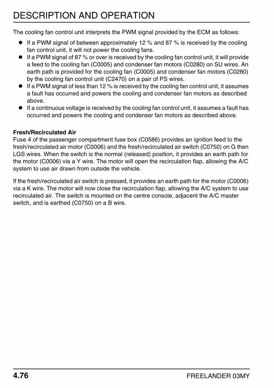
DESCRIPTION AND OPERATION
4.76 FREELANDER 03MY
The cooling fan control unit interprets the PWM signal provided by the ECM as follows:
If a PWM signal of between approximately 12 % and 87 % is received by the cooling fan control unit, it will not power the cooling fans.If a PWM signal of 87 % or over is received by the cooling fan control unit, it will provide a feed to the cooling fan (C0005) and condenser fan motors (C0280) on SU wires. An earth path is provided for the cooling fan (C0005) and condenser fan motors (C0280) by the cooling fan control unit (C2470) on a pair of PS wires.If a PWM signal of less than 12 % is received by the cooling fan control unit, it assumes a fault has occurred and powers the cooling and condenser fan motors as described above.If a continuous voltage is received by the cooling fan control unit, it assumes a fault has occurred and powers the cooling and condenser fan motors as described above.
Fresh/Recirculated AirFuse 4 of the passenger compartment fuse box (C0586) provides an ignition feed to the fresh/recirculated air motor (C0006) and the fresh/recirculated air switch (C0750) on G then LGS wires. When the switch is the normal (released) position, it provides an earth path for the motor (C0006) via a Y wire. The motor will open the recirculation flap, allowing the A/C system to use air drawn from outside the vehicle.
If the fresh/recirculated air switch is pressed, it provides an earth path for the motor (C0006) via a K wire. The motor will now close the recirculation flap, allowing the A/C system to use recirculated air. The switch is mounted on the centre console, adjacent the A/C master switch, and is earthed (C0750) on a B wire.

DESCRIPTION AND OPERATION
FREELANDER 03MY 4.77
AIR CONDITIONING (A/C) – K SERIES AND KV6
DESCRIPTIONGeneralThe air conditioning (A/C) system will only operate when the engine is running. The A/C system is switched on and off by pressing the switch mounted on the centre console. When the switch is pressed, an LED mounted within the switch illuminates to inform the driver the system is operational. For more information on LED operation, refer to the Interior Illumination section of this manual. + INTERIOR ILLUMINATION.
The position of the rotary heater control determines the amount of warm air from the heater matrix blended with cool air from the A/C evaporator, and hence the temperature of the air output from the heater ducts.
NOTE: The blower switch must be in at least position 1 for the A/C system to operate.
The A/C system is automatically switched on when either the screen or screen/feet positions are selected via the rotary distribution control knob.
NOTE: The A/C LED will not illuminate under these conditions.
For more information on heater operation, refer to the Heater Blower section of this manual. + HEATER BLOWER.
OPERATIONGeneralFeed from the positive battery terminal (C0192) is supplied to fusible link 1, fusible link 5, and the main relay (C0632) on an R wire. All are located within the engine compartment fuse box.
The earth path for the main relay coil (C0576 on K Series vehicles, C0578 on KV6 vehicles) is controlled by the Engine Control Module (ECM) (C0913 on K Series vehicles, C0371 on KV6 vehicles) on a WK wire. The energised main relay provides a feed to fuse 4, which is also located in the engine compartment fuse box. For more details on main relay operation, refer to the Engine Management Systems – MEMS or Engine Management Systems – Siemens (All Except NAS) section of the System Description and Operation Workshop manual.
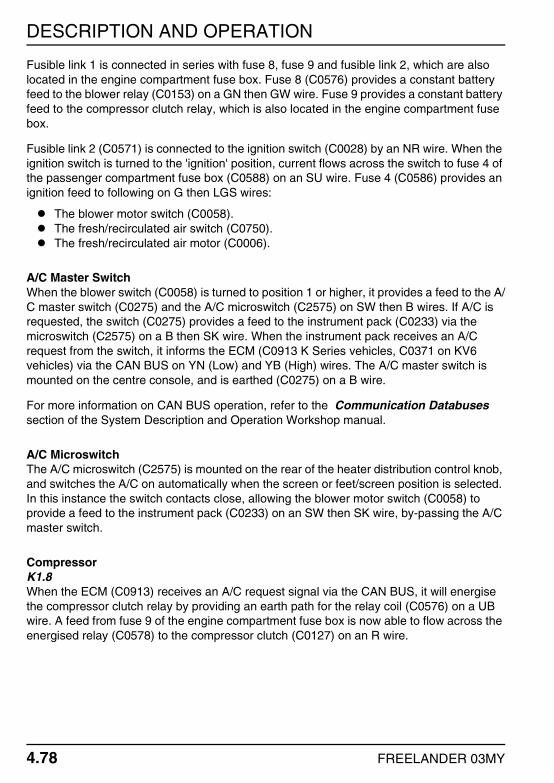
DESCRIPTION AND OPERATION
4.78 FREELANDER 03MY
Fusible link 1 is connected in series with fuse 8, fuse 9 and fusible link 2, which are also located in the engine compartment fuse box. Fuse 8 (C0576) provides a constant battery feed to the blower relay (C0153) on a GN then GW wire. Fuse 9 provides a constant battery feed to the compressor clutch relay, which is also located in the engine compartment fuse box.
Fusible link 2 (C0571) is connected to the ignition switch (C0028) by an NR wire. When the ignition switch is turned to the 'ignition' position, current flows across the switch to fuse 4 of the passenger compartment fuse box (C0588) on an SU wire. Fuse 4 (C0586) provides an ignition feed to following on G then LGS wires:
The blower motor switch (C0058).The fresh/recirculated air switch (C0750).The fresh/recirculated air motor (C0006).
A/C Master SwitchWhen the blower switch (C0058) is turned to position 1 or higher, it provides a feed to the A/C master switch (C0275) and the A/C microswitch (C2575) on SW then B wires. If A/C is requested, the switch (C0275) provides a feed to the instrument pack (C0233) via the microswitch (C2575) on a B then SK wire. When the instrument pack receives an A/C request from the switch, it informs the ECM (C0913 K Series vehicles, C0371 on KV6 vehicles) via the CAN BUS on YN (Low) and YB (High) wires. The A/C master switch is mounted on the centre console, and is earthed (C0275) on a B wire.
For more information on CAN BUS operation, refer to the Communication Databuses section of the System Description and Operation Workshop manual.
A/C MicroswitchThe A/C microswitch (C2575) is mounted on the rear of the heater distribution control knob, and switches the A/C on automatically when the screen or feet/screen position is selected. In this instance the switch contacts close, allowing the blower motor switch (C0058) to provide a feed to the instrument pack (C0233) on an SW then SK wire, by-passing the A/C master switch.
CompressorK1.8When the ECM (C0913) receives an A/C request signal via the CAN BUS, it will energise the compressor clutch relay by providing an earth path for the relay coil (C0576) on a UB wire. A feed from fuse 9 of the engine compartment fuse box is now able to flow across the energised relay (C0578) to the compressor clutch (C0127) on an R wire.

DESCRIPTION AND OPERATION
FREELANDER 03MY 4.79
KV6When the ECM (C0371) receives an A/C request signal via the CAN BUS, it will energise the compressor clutch relay by providing an earth path for the relay coil (C0578) on a BR wire. A feed from fuse 9 of the engine compartment fuse box is now able to flow across the energised relay (C0575) to the compressor clutch (C0127) on an R wire.
Instrument PackThe instrument pack (C0230) acts as a gateway, relaying CAN messages to and from different components throughout the vehicle as follows:
Pressure SensorThe pressure sensor is located in the high pressure A/C line adjacent the compressor, and replaces the more traditional trinary pressure switch. The ECM (C0913 on K Series vehicles, C0371 on KV6 vehicles) provides a 5 V reference voltage to the pressure sensor (C1257) on a UO wire. The pressure sensor (C1257) is provided an earth path by the ECM (C0913 on K Series vehicles, C0371 on KV6 vehicles) on a PB wire.
The pressure sensor (C1257) provides the ECM (C0913 on K Series vehicles, C0371 on KV6 vehicles) a signal feed on a UG wire. The value of this signal feed is dependent upon the pressure within the A/C system. The ECM uses this feed to determine the pressure within the A/C system, enabling it to carry out the following tasks:
To provide a safety cut-out function if the pressure within the A/C system goes either too high or too low.To control the speed of the cooling and condenser fans via the cooling fan control unit.To help control engine idle speed.
Evaporator Temperature SensorThe evaporator temperature sensor is used to ensure the evaporator doesn't freeze. The ECM (C0913 on K Series vehicles, C0371 on KV6 vehicles) provides a feed to the evaporator temperature sensor on a GO wire (GU on KV6 vehicles). The sensor is provided an earth path via the ECM (C0913 on K Series vehicles, C0371 on KV6 vehicles) on a BO wire (PB on KV6 vehicles).
NOTE: The ECM also uses the evaporator temperature sensor signal in conjunction with the pressure sensor signal to help control engine idle speed.

DESCRIPTION AND OPERATION
4.80 FREELANDER 03MY
Cooling Fan Control UnitFusible link 5 of the engine compartment fuse box (C0573) provides a constant battery feed to the cooling fan control unit (C0208) on an NG wire. Fuse 4 of the engine compartment fuse box (C0575) provides a feed to the cooling fan control unit (C1680) on an NK wire when the main relay in energised. The cooling fan control unit (C0208) is earthed on a B wire.
To control cooling fan and condenser fan speed, the ECM (C0913 on K Series vehicles, C0371 on KV6 vehicles) provides the cooling fan control unit (C1680) a Pulse Width Modulated (PWM) signal on a UW wire (UR then UW on KV6 vehicles). The frequency of the pulses supplied by the ECM determines the speed the cooling fan control unit will drive the cooling fan and condenser fan motors.
The cooling fan control interprets the PWM signal provided by the ECM as follows:
If a PWM signal of between approximately 12 % and 87 % is received by the cooling fan control unit , it will not power the cooling fans.If a PWM signal of 87 % or over is received by the cooling fan control unit, it will provide a feed to the cooling fan (C0005) and condenser fan motors (C0280) on SU wires. An earth path is provided for the cooling fan (C0005) and condenser fan motors (C0280) by the cooling fan control unit (C2470) on a pair of PS wires.If a PWM signal of less than 12 % is received by the cooling fan control unit, it assumes a fault has occurred and powers the cooling and condenser fan motors as described above.If a continuous voltage is received by the cooling fan control unit, it assumes a fault has occurred and powers the cooling and condenser fan motors as described above.
Fresh/Recirculated AirFuse 4 of the passenger compartment fuse box (C0586) provides an ignition feed to the fresh/recirculated air motor (C0006) and the fresh/recirculated air switch (C0750) on G then LGS wires. When the switch is the normal (released) position, it provides an earth path for the motor (C0006) via a Y wire. The motor will open the recirculation flap, allowing the A/C system to use air drawn from outside the vehicle.
If the fresh/recirculated air switch is pressed, it provides an earth path for the motor (C0006) via a K wire. The motor will now close the recirculation flap, allowing the A/C system to use recirculated air. The switch is mounted on the centre console, adjacent the A/C master switch, and is earthed (C0750) on a B wire.
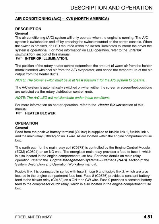
DESCRIPTION AND OPERATION
FREELANDER 03MY 4.81
AIR CONDITIONING (A/C) – KV6 (NORTH AMERICA)
DESCRIPTIONGeneralThe air conditioning (A/C) system will only operate when the engine is running. The A/C system is switched on and off by pressing the switch mounted on the centre console. When the switch is pressed, an LED mounted within the switch illuminates to inform the driver the system is operational. For more information on LED operation, refer to the Interior Illumination section of this manual. + INTERIOR ILLUMINATION.
The position of the rotary heater control determines the amount of warm air from the heater matrix blended with cool air from the A/C evaporator, and hence the temperature of the air output from the heater ducts.
NOTE: The blower switch must be in at least position 1 for the A/C system to operate.
The A/C system is automatically switched on when either the screen or screen/feet positions are selected via the rotary distribution control knob.
NOTE: The A/C LED will not illuminate under these conditions.
For more information on heater operation, refer to the Heater Blower section of this manual. + HEATER BLOWER.
OPERATIONGeneralFeed from the positive battery terminal (C0192) is supplied to fusible link 1, fusible link 5, and the main relay (C0632) on an R wire. All are located within the engine compartment fuse box.
The earth path for the main relay coil (C0578) is controlled by the Engine Control Module (ECM) (C0604) on an NG wire. The energised main relay provides a feed to fuse 4, which is also located in the engine compartment fuse box. For more details on main relay operation, refer to the Engine Management Systems – Siemens (NAS) section of the System Description and Operation Workshop manual.
Fusible link 1 is connected in series with fuse 8, fuse 9 and fusible link 2, which are also located in the engine compartment fuse box. Fuse 8 (C0576) provides a constant battery feed to the blower relay (C0153) on a GN then GW wire. Fuse 9 provides a constant battery feed to the compressor clutch relay, which is also located in the engine compartment fuse box.

DESCRIPTION AND OPERATION
4.82 FREELANDER 03MY
Fusible link 2 (C0571) is connected to the ignition switch (C0028) by an NR wire. When the ignition switch is turned to the 'ignition' position, current flows across the switch to fuse 4 of the passenger compartment fuse box (C0588) on an SU wire. Fuse 4 (C0586) provides an ignition feed to following on G then LGS wires:
The blower motor switch (C0058).The fresh/recirculated air switch (C0750).The fresh/recirculated air motor (C0006).
A/C Master SwitchWhen the blower switch (C0058) is turned to position 1 or higher, it provides a feed to the A/C master switch (C0275) and the A/C microswitch (C2575) on SW then B wires. If A/C is requested, the switch (C0275) provides a feed to the instrument pack (C0233) via the microswitch (C2575) on a B then SK wire. When the instrument pack receives an A/C request from the switch, it informs the ECM (C0913 K Series vehicles, C0371 on KV6 vehicles) via the CAN BUS on YN (Low) and YB (High) wires. The A/C master switch is mounted on the centre console, and is earthed (C0275) on a B wire.
For more information on CAN BUS operation, refer to the Communication Databuses section of the System Description and Operation Workshop manual.
A/C MicroswitchThe A/C microswitch (C2575) is mounted on the rear of the heater distribution control knob, and switches the A/C on automatically when the screen or feet/screen position is selected. In this instance the switch contacts close, allowing the blower motor switch (C0058) to provide a feed to the instrument pack (C0233) on an SW then SK wire, by-passing the A/C master switch.
CompressorWhen the ECM (C0331) receives an A/C request signal via the CAN BUS, it will energise the compressor clutch relay by providing an earth path for the relay coil (C0576) on a UB wire. A feed from fuse 9 of the engine compartment fuse box is now able to flow across the energised relay (C0575) to the compressor clutch (C0127) on an R wire.
Instrument PackThe instrument pack (C0230) acts as a gateway, relaying CAN messages to and from different components throughout the vehicle as follows:

DESCRIPTION AND OPERATION
FREELANDER 03MY 4.83
Pressure SensorThe pressure sensor is located in the high pressure A/C line adjacent the compressor, and replaces the more traditional trinary pressure switch. The instrument pack (C0230) provides a 5 V reference voltage to the pressure sensor (C1257) on a UO wire. The pressure sensor (C1257) is provided an earth path via the instrument pack (C0230) on a PB wire.
The pressure sensor (C1257) provides the instrument pack (C0230) a signal feed on a UG wire. The value of this signal feed is dependent upon the pressure within the A/C system. The instrument pack relays this information to the ECM via the CAN BUS. The ECM uses this to determine the pressure within the A/C system, enabling it to carry out the following tasks:
To provide a safety cut-out function if the pressure within the A/C system goes either too high or too low.To control the speed of the cooling and condenser fans via the cooling fan control unit.To help control engine idle speed.
Evaporator Temperature SensorThe evaporator temperature sensor is used to ensure the evaporator doesn't freeze. The instrument pack (C0230) provides a feed to the evaporator temperature sensor (C0417) on a GO wire. The sensor (C0417) is earthed on a B wire. The instrument pack relays evaporator temperature sensor status to the ECM via the CAN BUS.
NOTE: The ECM also uses the evaporator temperature sensor signal in conjunction with the pressure sensor signal to help control engine idle speed.
Cooling Fan Control UnitFusible link 5 of the engine compartment fuse box (C0573) provides a constant battery feed to the cooling fan control unit (C0208) on an NG wire. Fuse 4 of the engine compartment fuse box (C0575) provides a feed to the cooling fan control unit (C1680) on an NK wire when the main relay in energised (see above). The cooling fan control unit (C0208) is earthed on a B wire.
To control cooling fan and condenser fan speed, the ECM (C0331) provides the cooling fan control unit (C1680) a Pulse Width Modulated (PWM) signal on a UW wire. The frequency of the pulses supplied by the ECM determines the speed the cooling fan control unit will drive the cooling fan and condenser fan motors.

DESCRIPTION AND OPERATION
4.84 FREELANDER 03MY
The cooling fan control unit interprets the PWM signal provided by the ECM as follows:
If a PWM signal of between approximately 12 % and 87 % is received by the cooling fan control unit, it will not power the cooling fans.If a PWM signal of 87 % or over is received by the cooling fan control unit, it will provide a feed to the cooling fan (C0005) and condenser fan motors (C0280) on SU wires. An earth path is provided for the cooling fan (C0005) and condenser fan motors (C0280) by the cooling fan control unit (C2470) on a pair of PS wires.If a PWM signal of less than 12 % is received by the cooling fan control unit, it assumes a fault has occurred and powers the cooling and condenser fan motors as described above.If a continuous voltage is received by the cooling fan control unit, it assumes a fault has occurred and powers the cooling and condenser fan motors as described above.
Fresh/Recirculated AirFuse 4 of the passenger compartment fuse box (C0586) provides an ignition feed to the fresh/recirculated air motor (C0006) and the fresh/recirculated air switch (C0750) on G then LGS wires. When the switch is the normal (released) position, it provides an earth path for the motor (C0006) via a Y wire. The motor will open the recirculation flap, allowing the A/C system to use air drawn from outside the vehicle.
If the fresh/recirculated air switch is pressed, it provides an earth path for the motor (C0006) via a K wire. The motor will now close the recirculation flap, allowing the A/C system to use recirculated air. The switch is mounted on the centre console, adjacent the A/C master switch, and is earthed (C0750) on a B wire.

DESCRIPTION AND OPERATION
FREELANDER 03MY 4.85
HEATER BLOWER
DESCRIPTIONGeneralThe heater is operated from three rotary controls located in the centre console. Two of the controls operate the temperature and air flow distribution. The third control operates the four speed blower motor.
A resistor pack is mounted on the RH side of the heater unit. The resistor pack supplies reduced voltages to the blower motor for fan speed one, two, and three. Fan speed four drives the blower motor at full speed with a direct 12V supply.
The blower motor will only operate when the ignition switch is in the 'ignition' position.
OPERATIONGeneralFeed from the positive battery terminal (C0192) is supplied to fusible link 1 of the engine compartment fuse box (C0632) on an R wire. Fusible link 1 is connected in series with fuse 8 and fusible link 2, which are also located in the engine compartment fuse box.
Fusible link 2 (C0571) is connected to the ignition switch (C0028) by an NR wire. When the ignition switch is turned to the 'ignition' position, current flows across the switch (C0028) to fuse 4 of the passenger compartment fuse box (C0588) on an SU wire. Fuse 4 (C0586) provides an ignition feed to the following on G then LGS wires:
The fresh/recirculated air motor (C0006).The fresh/recirculated air switch (C0750).The blower motor switch (C0058).
Blower Speed 1If blower speed 1 is selected, current flows across the blower motor switch (C0058) to the resistor pack (C0425) on an RK wire. The resistor pack (C0425) is connected to the blower motor (C0056) by a GK then G wire. As current has to flow through the greatest value resistor, the blower motor operates at slow speed.
The blower motor (C0056) is earthed on a B wire.
Blower Speed 2If blower speed 2 is selected, current flows across the blower motor switch (C0058) to the resistor pack (C0425) on an RY wire. The resistor pack (C0425) is connected to the blower motor (C0056) by a GK then G wire. As current has to flow through the medium value resistor, the blower motor operates at a slightly increased speed.

DESCRIPTION AND OPERATION
4.86 FREELANDER 03MY
Blower Speed 3If blower speed 3 is selected, current flows across the blower motor switch (C0058) to the resistor pack (C0425) on an RG wire. The resistor pack (C0425) is connected to the blower motor (C0056) by a GK then G wire. As current has to flow through the smallest value resistor, the blower motor operates at an increased speed.
Blower Speed 4If blower speed 4 is selected, current flows across the blower motor switch (C0058) to the blower motor relay coil (C0153) on an RS wire. The relay coil (C0153) is earthed on a BS then B wire. The energised blower relay allows a feed from fuse 8 of the engine compartment fuse box (C0576) across the closed relay switch (C0153) directly to the blower motor (C0056) on a GR then G wire. As current by-passes the resistor pack, the blower motor operates at high speed.
Fresh/Recirculated AirFuse 4 of the passenger compartment fuse box (C0586) provides an ignition feed to the fresh/recirculated air motor (C0006) and the fresh/recirculated air switch (C0750) on G then LGS wires. When the switch is the normal (released) position, it provides an earth path for the motor (C0006) via a Y wire. The motor will open the recirculation flap, allowing the heater to use air drawn from outside the vehicle.
If the fresh/recirculated air switch is pressed, it provides an earth path for the motor (C0006) via a K wire. The motor will now close the recirculation flap, allowing the heater system to use recirculated air. The switch is mounted on the centre console and is earthed (C0750) on a B wire.

DESCRIPTION AND OPERATION
FREELANDER 03MY 4.87
FUEL BURNING HEATER (FBH)
DESCRIPTIONGeneralA Fuel Burning Heater (FBH) is used to compensate for the lower operating temperatures of diesel engines by heating engine coolant before it enters the heater matrix. For a detailed description of FBH operation, refer to the Heating and Ventilation section of the System Description and Operation Workshop manual.
OPERATIONGeneralFeed from the positive battery terminal (C0192) is supplied to fusible link 1 of the engine compartment fuse box (C0632) on an R wire. Fusible link 1 is connected in series with fuse 5, which is also located in the engine compartment fuse box. Fuse 5 (C0576) provides a constant battery feed to the Fuel Burning Heater (FBH) (C0926) on a PN wire. The FBH (C0926) is earthed on a B wire.
When the engine is running, the alternator (C0226) provides the Engine Control Module (ECM) (C0606) a Pulse Width Modulated (PWM) signal on a U wire. When the ECM (C0331) receives this signal it provides a feed to the FBH temperature sensor (C0714) on an NY wire. The FBH temperature sensor measures ambient air temperature, and is a normally open switch.
If an ambient air temperature of below 5 °C is measured, the FBH temperature sensor closes. The ECM feed can now flow across the sensor (C0714) to the FBH (C0925) on an SG wire. On receiving this feed, the FBH will power the FBH pump.
The FBH (C0925) sends a PWM signal to the FBH pump (C0920) on a WU wire. By varying the frequency of the pulses, the FBH can control the pump to operate at one of three speeds. The pump (C0920) is earthed on a B wire.
Diagnostic SocketThe FBH can be interrogated using TestBook or T4 via the diagnostic socket. The diagnostic socket (C0040) is connected to the FBH (C0925) by a K wire.

DESCRIPTION AND OPERATION
4.88 FREELANDER 03MY
POSITIVE TEMPERATURE COEFFICIENT (PTC) HEATER
DESCRIPTIONGeneralThe Positive Temperature Coefficient (PTC) heater replaces the Fuel Burning Heater (FBH) fitted to Td4 vehicles in markets of a moderate climate. The PTC heater, like the FBH, is an auxiliary heating system that compensates for the relatively low coolant temperature inherent in the diesel engine.
The PTC heater is an electrical heating element installed in the heater assembly on the downstream side of the heater matrix. For a more detailed description of PTC heater operation, refer to the Heating and Ventilation section of the System Description and Operation Workshop manual.
NOTE: Cold climate specification vehicles still maintain the FBH.
OPERATIONGeneralFeed from the positive battery terminal (C0192) is supplied to fusible link 1 of the engine compartment (C0632) on an R wire. Fusible link 1 is connected in series with fusible link 2, which is also located in the engine compartment fuse box.
Fusible link 2 (C0571) is connected to the ignition switch (C0028) by an NR wire. When the ignition switch is turned to the 'ignition' position, current flows across the switch (C0028) to fuse 4 of the passenger compartment fuse box (C0588) on an SU wire. Fuse 4 (C0586) provides an ignition feed to the blower motor switch (C0058) on a G then LGS wire.
The battery (C0192) also provides a feed to fusible link 1 (C1875) located in the fuse holder on an R wire. Fusible link 1 (C1875) provides a constant battery feed to PTC relay 2 (C0157) on an N wire.
PTC SwitchIf the rotary blower motor switch is turned to position 1 or higher, current from fuse 4 of the passenger compartment fuse box (C0586) flows across the switch (C0058) to the PTC switch (C0422) on an SW wire. The PTC switch is mounted on the rear of the rotary temperature control switch. When the temperature control switch is in the cold to warm position (i.e. less than approximately 1 o'clock), the PTC switch contacts are open. If the temperature control switch is turned to the warm to hot position (i.e. approximately 1 o'clock and above) the PTC switch contacts close. This allows current to flow from the PTC switch (C0422) to PTC relay 1 (C0154) on a GW wire.

DESCRIPTION AND OPERATION
FREELANDER 03MY 4.89
PTC RelaysOperation of the PTC heater is controlled by two relays. PTC relay 1 is the control relay and is mounted on the side of the E-box. PTC relay 2 is the power relay and is mounted on the engine bulkhead, behind the engine compartment fuse box.
PTC Relay 1The coil of PTC relay 1 (C0154) receives a feed from the PTCswitch (C0422) on a GW wire. The relay coil (C0154) is earthed on a B wire. When energised, PTC relay 1 (C0154) provides an earth path for PTC relay 2 (C0157) on a G then GY wire.
PTC Relay 2The coil of PTC relay 2 (C0157) receives a feed from the fuel pump relay (C0572) on a WP then GR wire. When PTC relay 1 is energised, it provides an earth path for the relay coil of PTC relay 2 on a G then GY wire. This allows a battery feed from fusible link 1 (C1875), located in the fuse holder, to flow across the closed relay switch contacts to fuse 1, fuse 2, and fuse 3 (C1876) on B wires. All are located in the fuse holder.
For more information on fuel pump relay operation, refer to the Fuel Pump section of this manual. + FUEL PUMP.
PTC HeaterThe PTC heater is powered via three fuses located in an additional fuse holder. The fuse holder is mounted on the side of the E-box. Fuses 1, 2, and 3 (C1876) are provided a feed by the energised PTC relay 2 (C0157) on B wires, and power the PTC heater elements (C2123) as follows:
Fuse 1 is connected to PTC heater element 3 by a BP wire.Fuse 2 is connected to PTC heater element 2 by a BN wire.Fuse 3 is connected to PTC heater element 3 by a BG wire.
Engine Control Module (ECM)On vehicles fitted with manual transmission, a feed is provided to the ECM (C0331) on a G then GY wire when the PTC heater is operational. This signal feed informs the ECM to raise the engine idle speed.

DESCRIPTION AND OPERATION
4.90 FREELANDER 03MY
COOLING FANS
DESCRIPTIONK SeriesK Series vehicles are fitted with a single cooling fan, which is mounted on the rear face of the radiator. Operation of the single speed cooling fan is controlled by the Engine Control Module (ECM) via the cooling fan relay.
NOTE: Vehicles fitted with Air Conditioning (A/C) are also fitted with a condenser fan and a cooling fan control unit. For more information, refer to the 'Air Conditioning (A/C) – K Series and KV6' section of this manual.
+ AIR CONDITIONING (A/C) – K SERIES AND KV6.
The cooling fan will also operate after the ignition has been switched off to control rising engine bay temperatures after the engine has stopped running.
KV6 and Td4KV6 and Td4 vehicles are fitted with a fan to control the temperature within the E-box. If the temperature within the E-box reaches 35 °C (95 °F), the fan operates until the temperature drops to 27 °C (80 °F).
For information on cooling fan operation, refer to the Air Conditioning (A/C) – Td4 , Air Conditioning (A/C) – K Series and KV6, or Air Conditioning (A/C) – KV6 (North America) section of this manual. + AIR CONDITIONING (A/C) – Td4. + AIR CONDITIONING (A/C) – K SERIES AND KV6. + AIR CONDITIONING (A/C) – KV6 (NORTH AMERICA).
OPERATIONTd4Feed from the positive battery terminal (C0192) is supplied to fusible link 1 and the main relay (C0632) on an R wire. Both are located in the engine compartment fuse box. Operation of the main relay (C0576) is controlled by the Engine Control Module (ECM) (C0603) on a WK wire. The energised main relay provides a feed to fuse 4, which is also located in the engine compartment fuse box.
Fusible link 1 is connected in series with fusible link 7. Fusible link 7 provides a constant battery feed to the starter relay, which is also located in the engine compartment fuse box. Operation of the starter relay (C0576) is controlled by the ECM (C0059) on an RW wire. The relay coil (C0576) is earthed on a B wire. The energised starter relay (C0572) provides a feed to the E-box fan (C0646) on an NR wire.

DESCRIPTION AND OPERATION
FREELANDER 03MY 4.91
E-box FanFuse 4 of the engine compartment fuse box (C0575) provides a feed to the E-box temperature sensor (C1258) on an NK wire. The temperature sensor is a thermostatic switch. When the temperature within the E-box reaches 35 °C (95 °F) the switch contact close. Current flows across the switch contacts (C1258) to the E-box fan (C0646) on an NK wire. The E-box fan (C0646) is earthed on a B wire.
When the temperature within the E-box drops to 27 °C (80 °F), the switch contacts within the sensor open, cutting the feed to the E-box fan.
K SeriesFeed from the positive battery terminal (C0192) is supplied to fusible link 5, and the main relay on an R wire. Both are located in the engine compartment fuse box. Fusible link 5 (C0573) provides a constant battery feed to the cooling fan relay (C0019) on an SU wire.
Operation of the main relay (C0576) is controlled by the ECM (C0913) on a WK wire. When energised, the main relay provides a feed to fuse 4, which is also located in the engine compartment fuse box. Fuse 4 (C0575) is connected to the cooling fan relay (C0019) by an NK wire.
Engine Coolant Temperature (ECT) SensorThe ECM monitors Engine Coolant Temperature (ECT) via the ECT sensor. The ECM (C0914) provides a feed to the ECT sensor (C0169) on a KG wire. As ECT rises, the resistance of the sensor falls. By measuring the voltage returned from the ECT sensor (C0169) on a KB wire, the ECM (C0914) can determine ECT.
Cooling FanWhen the ECM (C0913) registers a temperature of 102 °C (215 °F) via the ECT sensor, it energises the cooling fan relay by providing an earth path for the relay coil (C0019) on a UR wire. The energised cooling fan relay (C0019) provides a feed to the cooling fan motor (C0005) on an NR wire. The cooling fan motor (C0005) is earthed on a B wire.
KV6Feed from the positive battery terminal (C0192) is supplied to fusible link 3 and the main relay (C0632) on an R wire. Both are located in the engine compartment fuse box. Operation of the main relay (C0578) is controlled by the ECM (C0604 on KV6 NAS vehicles, C0371 on KV6 ROW vehicles) on a WK wire (NG on KV6 NAS vehicles). The energised main relay provides a feed to fuse 4, which is also located in the engine compartment fuse box.
Fusible link 3 (C0571) is connected to the ignition switch (C0028) by an N wire. When the ignition switch is turned to the 'ignition' position, current flows across the switch (C0028) to fuse 5 of the passenger compartment fuse box (C0588) on a WR wire. Fuse 5 (C0581) provides an ignition feed to the E-box fan (C0646) on a WR wire.

DESCRIPTION AND OPERATION
4.92 FREELANDER 03MY
E-box FanFuse 4 of the engine compartment fuse box (C0575) provides a feed to the E-box temperature sensor (C1258) on an NK wire. The temperature sensor is a thermostatic switch. When the temperature within the E-box reaches 35 °C (95 °F) the switch contact close. Current flows across the switch contacts (C1258) to the E-box fan (C0646) on an NK wire. The E-box fan (C0646) is earthed on a B wire.
When the temperature within the E-box drops to 27 °C (80 °F), the switch contacts within the sensor open, cutting the feed to the E-box fan.

DESCRIPTION AND OPERATION
FREELANDER 03MY 4.93
HEATED REAR WINDOW (HRW)
DESCRIPTIONGeneralThe HRW comprises eleven metallic strips bonded to the inside surface of the tail door glass to form an element. The metallic strips terminate in two larger strips at the bottom of the glass. Two connectors bonded to the terminations provide attachment of the supply and earth connections.
The HRW is controlled by the Central Control Unit (CCU) via a non latching switch mounted on the centre console. The switch has an illumination LED to show when the HRW is operational. The switch is also illuminated by a separate bulb when the side or headlamps are switched on. For more information on switch illumination, refer to the Interior Illumination section of this manual. + INTERIOR ILLUMINATION.
The CCU will only operate the HRW when all of the following conditions are met:
The HRW switch is pressed.The engine is running.The tail door window is closed.The roof is fitted (3 door models only).
NOTE: The HRW will not operate if the tail door window has not been calibrated. For more information on tail door window calibration, refer to the Windows section of this manual.
+ WINDOWS.
The CCU will switch the HRW off automatically after approximately 15 minutes.
OPERATIONGeneralFeed from the positive battery terminal (C0192) is supplied to fusible link 3 and fusible link 4 of the engine compartment fuse box (C0632) on an R wire. Fusible link 4 (C0574) provides a constant battery feed to the HRW relay and fuse 14 of the passenger compartment fuse box (C0587) on an NW wire.
NOTE: Only 3 door vehicles utilise fuse 14 for HRW operation.
The earth path for the HRW coil is controlled by the CCU (C0592), which is connected directly into the rear of the passenger compartment fuse box. The CCU will only provide an earth path for the relay coil if the ignition is switched on, and the engine is running.

DESCRIPTION AND OPERATION
4.94 FREELANDER 03MY
Fusible link 3 (C0571) is connected to the ignition switch (C0028) by an N wire. When the ignition switch is turned to the 'ignition' position, current flows across the switch (C0028) to fuse 8 of the passenger compartment fuse box (C0588) on a G wire. Fuse 8 provides an ignition feed to the CCU (C0593).
When the CCU receives an ignition feed, it provides a feed to the HRW switch (C0072) on a GY wire. When the switch is pressed, current flows across the switch contacts (C0072) to earth on a B wire. The first of two electrical switches within the CCU will now close.
When the ignition is switched on, the CCU (C0592) also provides a feed to the oil pressure switch (C0187) via the passenger compartment fuse box (C0581) on an NW then WN wire. The oil pressure switch contacts are closed when there is no oil pressure. When the engine is started, the rise in oil pressure causes the switch contacts to open. When the switch contacts open, the second electrical switch within the CCU closes.
When both electrical switches within the CCU are closed, the CCU (C0592) provides an earth path for the HRW relay coil via the passenger compartment fuse box (C0587) on a B wire. The energised HRW relay provides a feed to fuse 23, which is also located in the passenger compartment fuse box. Fuse 23 (C0583) provides a feed to the HRW element (C0381) on an N wire. The HRW element (C0382) is earthed on a B wire. Fuse 23 (C0580) also provides a feed to the switch illumination LED (C0072) on an NG wire. The LED (C0072) is earthed on a B wire.
The CCU will de-energise the HRW relay by removing its earth path after approximately 15 minutes has elapsed, or if the ignition is switched off.
Tail Door Window LiftThe HRW will not operate if the tail door glass is not in the fully closed position. If the tail door window is opened while the HRW is operational, the CCU suspends the feed to the HRW element by de-energising the HRW relay. The CCU (C0428) monitors the condition of the tail door window via the tail door window switch (C0354) on BR and BK wires. The switch (C0354) is earthed on a B wire.
For more information on tail door window operation, refer to the Windows section of this manual. + WINDOWS.

DESCRIPTION AND OPERATION
FREELANDER 03MY 4.95
Roof On Switch (3 Door Vehicles Only)Fuse 14 of the passenger compartment fuse box (C0583) provides a constant battery feed to the roof on switch (C0497) on a P wire. The roof on switch is closed when the hard back is fitted, or the soft back is in the fitted position. In this instance, current flows across the switch (C0497) to the CCU (C0428) on a PY wire. If the hard back is removed (or the soft back is folded down) the roof on switch becomes open circuit, and the feed to the CCU is removed. The CCU will now inhibit operation of the HRW.

DESCRIPTION AND OPERATION
4.96 FREELANDER 03MY
HEATED FRONT SCREEN (HFS)
DESCRIPTIONGeneralThe Heated Front Screen (HFS) consists of two heater elements which are embedded into the LH and RH sides of the windscreen. Two connectors at the base of the windscreen provide the power feed and an integral earth for each of the heater elements.
Operation of the HFS is controlled by the CCU and a non latching switch on the centre console. The switch contains an LED which illuminates while the HFS is on. The CCU de-energises the HFS relay after approximately 5 minutes, when the switch is pressed again or if the engine stops.
OPERATIONGeneralFeed from the positive battery terminal (C0192) is supplied to fusible link 3 of the engine compartment fuse box (C0632) on an R wire and the Heated Front Screen (HFS) relay (C0994) on an N wire.
Fusible link 3 (C0571) provides a constant battery feed to the ignition switch (C0028) on an N wire. When the ignition switch is turned to the 'ignition' position, current flows across the switch (C0028) to fuse 8 of the passenger compartment fuse box (C0588) on a G wire. Fuse 8 provides an ignition feed to the CCU (C0593), which is mounted on the rear of the passenger compartment fuse box. The CCU (C0593) is earthed via the passenger compartment fuse box (C0587) on a B wire.
HFS RelayThe battery (C0192) provides a constant battery feed to the HFS relay coil (C0994) on an N wire. The earth path for the relay coil (C0994) is controlled by the CCU (C0429) on an SB wire.
The CCU will only provide an earth path for the HFS relay coil if all of the following are present:
The ignition is on.The engine is running.The HFS switch is pressed.
The CCU (C0592) monitors the condition of the oil pressure switch (C0187) on a WN wire. The oil pressure switch contacts are closed when there is no oil pressure. When the engine is started, the rise in oil pressure causes the switch contacts to open.

DESCRIPTION AND OPERATION
FREELANDER 03MY 4.97
HFS SwitchThe CCU (C0429) monitors the condition of the HFS switch (C0131) by providing a feed on a KO wire. When the switch is pressed the CCU senses the momentary earth path, and (providing all other conditions are met) energises the HFS relay. The switch (C0131) is earthed on a B wire.
HFS ElementsThe energised HFS relay (C0994) provides a feed to fuse A and fuse B (C1860) on a pair of NW wires. Fuse A (C1860) provides a feed to the LH screen element (C0247) on a PS wire. Fuse B (C1860) provides a feed to the RH screen element (C0246) on a PK wire (PW on vehicles from 03MY).
The energised HFS relay (C0994) also provides a feed to fuse C (C1860) on an NW wire. Fuse C (C1860) provides a feed to the HFS switch tell-tale LED (C0131) on a PK wire. The LED (C0131) is earthed on a B wire.

DESCRIPTION AND OPERATION
4.98 FREELANDER 03MY
WIPERS AND WASHERS
DESCRIPTIONFrontWipersOperation of the windscreen wipers is controlled by the Central Control Unit (CCU). There are four modes of wiper operation. These are selectable from the RH column stalk when the ignition switch is in the 'ignition' position.
NOTE: Windscreen wiper operation is temporarily suspended while the engine in cranking.
The modes of windscreen wiper operation are:
Slow wipe.Fast wipe.Intermittent wipe.Flick wipe.
WashersThe windscreen washer jets are controlled by the CCU and are operated by pulling the RH column stalk back against spring pressure. When the washer jets are operated, the windscreen wipers will start operating at slow speed after a delay of approximately 0.6 seconds. The wipers will continue to operate at slow speed until approximately 2 seconds after the RH wiper stalk is released.
RearWiperThe rear wiper is switched on and off by pressing the switch mounted on the RH side of the instrument pack. The rear wiper is controlled by the Central Control Unit (CCU) and will only operate when the ignition switch is in the 'ignition' position.
NOTE: Rear wiper operation will NOT be suspended while the engine is cranking.
The rear wiper will stop operating and return to its park position if any of the following occur:
The tail door is opened.The tail door window is opened.The roof is removed (3 door vehicles only).
If the windscreen wipers are in operation and reverse gear is selected, the rear wiper will automatically operate at slow speed, irrespective of rear wiper switch position. The rear wiper will stop operating when reverse gear is de-selected.

DESCRIPTION AND OPERATION
FREELANDER 03MY 4.99
WasherThe rear washer is operated by pressing the non-latching switch mounted on the RH side of the instrument pack. The washer will operate until the switch is released.
The rear wiper will start operating at slow speed as soon as the washer switch is depressed, and will continue to operate at slow speed for approximately 6 seconds after the switch is released.
OPERATIONFrontGeneralFeed from the positive battery terminal (C0192) is supplied to fusible link 3 of the engine compartment fuse box (C0632) on an R wire. Fusible link 3 (C0571) is connected to the ignition switch (C0028) by an N wire. When the ignition switch is turned to the 'ignition' position, current flows across the switch (C0028) to fuse 8 (C0588) on a G wire, and fuse 3 (C0588) on an NW wire. Both are located in the passenger compartment fuse box.
Fuse 8 and fuse 3 (C0593) both provide an ignition feed to the front wiper relay contained within the Central Control Unit (CCU). The CCU (C0593) is earthed via the passenger compartment fuse box (C0587) on a B wire.
Intermittent WipeFuse 3 of the passenger compartment fuse box (C0580) provides an ignition feed to the wiper switch (C0035) on an LG wire, and the variable wipe potentiometer (C0320) on a GY wire. When the wiper switch is moved to the intermittent wipe position, current flows across the switch (C0035) to the CCU (C0428) on a G wire.
The variable wipe potentiometer has 5 pre-set positions. The potentiometer (C0320) is connected to the CCU (C0429) by a WK wire. The voltage supplied to the CCU by the potentiometer is dependent upon its position. The CCU is able to determine the amount of delay to apply to the wipers by measuring the voltage provided on the WK wire.
When the CCU receives a feed from the intermittent wipe switch and the potentiometer, it provides an intermittent feed back to the wiper switch (C0035) on a LGK wire. The wiper switch (C0035) is connected to the wiper motor (C0030) by a ULG wire. Current flows across the motor slow speed windings and is earthed (C0030) on a B wire.
Slow WipeFuse 3 of the passenger compartment fuse box (C0580) provides an ignition feed to the wiper switch (C0035) on a G wire. When the wiper switch is moved to the slow wipe position, current flows across the switch (C0035) to the wiper motor (C0030) on a ULG wire. Current flows across the motor slow speed windings and is earthed (C0030) on a B wire.

DESCRIPTION AND OPERATION
4.100 FREELANDER 03MY
Fast WipeFuse 3 of the passenger compartment fuse box (C0580) provides an ignition feed to the wiper switch (C0035) on a G wire. When the wiper switch is moved to the fast wipe position, current flows across the switch (C0035) to the wiper motor (C0030) on a RG wire. Current flows across the motor fast speed windings and is earthed (C0030) on a B wire.
ParkFuse 3 of the passenger compartment fuse box (C0582) provides an ignition feed to the wiper motor park switch (C0030) on an LG wire. The park switch is closed with the wipers in any position other then the park position.
When the wipers are turned off, current flows across the park switch (C0030) to the CCU (C0430) on an NLG wire. The CCU (C0430) is connected to the wiper switch (C0035) by an LGK wire. The wiper switch (C0035) provides a feed to the wiper motor (C0040) on a ULG wire. Current flows across the motor slow speed windings and is earthed (C0030) on a B wire. When the wipers reach the park position, the switch contacts open and power to the wiper motor is cut.
WashersFuse 3 of the passenger compartment fuse box (C0580) provides an ignition feed to the washer switch (C0035) on an LG wire. When the RH column stalk is pulled back against spring pressure, current flows across the switch (C0035) to the washer pump (C0008) on a LGB wire. The washer pump (C0008) is earthed on a B wire.
The washer switch (C0035) also provides a feed to the CCU (C0428) on an LGB wire. When the CCU receives this feed, it initiates its programmed wash/wipe function.
RearGeneralFeed from the positive battery terminal (C0192) is provided to fusible link 3, and fusible link 4 of the engine compartment fuse box (C0632) on an R wire. Fusible link 4 (C0574) is connected to fuse 30 and fuse 14 of the passenger compartment fuse box (C0587) by an NW wire. Fuse 30 (C0583) provides a constant battery feed to the rear wiper relay (C0124) on a PR wire. Fuse 14 (C0583) provides a constant battery feed to the 'Roof On' switch (C0497) on a P wire.
Fusible link 3 (C0571) is connected to the ignition switch (C0028) by an N wire. When the ignition switch is turned to the 'ignition' position, current flows across the switch (C0028) to fuse 1 of the passenger compartment fuse box (C0588) on an NW wire. The ignition switch (C0028) also provides a feed to fuse 8 of the passenger compartment fuse box (C0588) on a G wire.

DESCRIPTION AND OPERATION
FREELANDER 03MY 4.101
WiperThe CCU (C0592) monitors the condition of the wiper switch (C0079) by providing a feed via the passenger compartment fuse box (C0589) on an RG wire. When the switch is pressed, current flows across the switch contacts (C0079) to earth on a B wire. When the CCU registers this earth, it provides a feed to the rear wiper relay (C0124) on a YB wire. The rear wiper relay contains two independent relays; a forward relay and a reverse relay.
The energised forward relay (C0124) is now able to provide a feed to the wiper motor (C0388) on a GR wire. Current flows across the motor windings (C0388) and back to the rear wiper relay (C0124) on a G wire.
To move the wiper back, the CCU (C0429) removes the feed to the wiper relay on a YB wire and provides a feed on a YW wire. This feed energises the reverse relay, which is earthed on a B wire.
The energised reverse relay (C0124) is now able to provide a feed to the wiper motor (C0388) on a G wire. Current flows across the motor windings (C0388) and back to the rear wiper relay (C0124) on a GR wire.
Off-Screen ParkThe CCU (C0428) monitors the off-screen park function of the rear wiper (C0388) by providing a signal feed on OB and NG wires. For more information on the off-screen park function, refer to the Wipers and Washers section of the Workshop manual.
Tail Door Window LiftThe rear wiper will not operate if the tail door glass is not in the fully closed position. If the tail door window is open. The CCU (C0428) monitors the condition of the tail door window via the tail door window switch (C0354) on BR and BK wires. The switch (C0354) is earthed on a B wire.
For more information on tail door window operation, refer to the Windows section of this manual. + WINDOWS.
WasherFuse 1 of the passenger compartment fuse box (C0589) provides an ignition feed to the washer switch (C0073) on a GY wire. When the switch is depressed, current flows across the switch contacts (C0073) to the washer pump relay (C0936) and the CCU (C0428) on GB wires.

DESCRIPTION AND OPERATION
4.102 FREELANDER 03MY
When the CCU receives this feed, it initiates its programmed wash/wipe function, and provides a feed to the rear wiper relay (C0124) on a YB wire. The rear wiper relay operates the rear wiper as described above.
The rear wiper relay (C0124) also provides a feed to the washer pump relay (C0936) on a GR wire. This energises the washer pump relay, which is earthed on a B wire. The energised washer pump relay (C0936) provides a feed to the washer pump (C0021) on a GB wire. The pump (C0021) is earthed on a B wire.
Tail Door SwitchThe CCU (C0428) monitors the condition of the tail door switch (C0616) by providing a feed on a BO wire. The tail door switch is open circuit when the tail door is closed. When the tail door is opened, the switch contacts close and an earth path is created on a B wire. Sensing this earth path, the CCU suspends operation of the rear wiper.
Roof On Switch (3 Door Vehicles Only)Fuse 14 of the passenger compartment fuse box (C0583) provides a constant battery feed to the roof on switch (C0497) on a P wire. The roof on switch is closed when the hard back is fitted, or the soft back is in the fitted position. In this instance, current flows across the switch (C0497) to the CCU (C0428) on a PY wire.
If the hard back is removed (or the soft back is folded down) the roof on switch becomes open circuit, and the feed to the CCU is removed. When the CCU registers this, it suspends operation of the rear wiper.

DESCRIPTION AND OPERATION
FREELANDER 03MY 4.103
BRAKE AND REVERSE LAMPS
DESCRIPTIONBrake LampsThree brake lamps are fitted to the rear of the vehicle. Two brake lamps are mounted above the rear bumper, and share a dual filament bulb with the tail lamps. A third, high mounted tail lamp is housed within a casting mounted on the tail door above the spare wheel.
NOTE: NAS vehicles are also fitted with a second pair of brake lamp bulbs. These operate in conjunction with the normal brake lamp bulbs. These secondary bulbs are also used as fog lamps. For more information of fog lamp operation, refer to the 'Fog Lamps' section of this manual.
+ FOG LAMPS.
The brake lamps are operated by the brake pedal switch, which is mounted on the pedal box, and will only operate when the ignition switch is in the 'ignition' position.
The brake lamps will also operate without operation of the brake pedal. If Hill Descent Control (HDC) is engaged, ABS ECU will operate the brake lamps, responding from signals from the ABS modulator.
For more details of HDC, refer to the Brakes section of the Workshop manual. For more information on ABS operation, refer to the Anti-lock Braking System (ABS) section of this manual. + ANTI-LOCK BRAKING SYSTEM (ABS).
Reverse LampsThe reverse lamps are incorporated into the tail lamp units, and will only operate when the ignition switch is in the 'ignition' position, and reverse gear is selected.
OPERATIONGeneralFeed from the positive battery terminal (C0192) is supplied to fusible link 3 of the engine compartment fuse box (C0632) on an R wire. Fusible link 3 (C0571) is connected to the ignition switch (C0028) by an N wire. When the ignition switch is turned to the 'ignition' position, current flows across the switch (C0028) to fuse 2 of the passenger compartment fuse box (C0588) on an NW wire.

DESCRIPTION AND OPERATION
4.104 FREELANDER 03MY
Fuse 2 (C0580) provides an ignition feed to the following on G wires:
The reverse lamp relay (C0935) (automatic transmission vehicles only).The brake pedal switch (C0075).
Fuse 2 (C0581) also provides an ignition feed to the reverse lamp switch (C0163) (K1.8 and Td4 manual transmission vehicles only) on a G wire.
Brake LampsThe brake pedal switch (C0075) is provided an ignition feed from fuse 2 of the passenger compartment fuse box (C0580) on a G wire. When the brake pedal is pressed, current flows across the switch (C0075) to the following on GP wires:
The RH brake lamp (C0125).The RH brake lamp (C0489) (NAS vehicles only).The LH brake lamp (C0121).The LH brake lamp (C0490) (NAS vehicles only).The Centre High Mounted Stop Lamp (CHMSL) (C0613).The trailer pick-up (C0499) (GP then R wire).The ABS ECU (C0501).
All brake lamps are earthed on a B wire. The trailer pick-up is earthed on a W then B wire
NOTE: The brake pedal switch (C0075) provides a second feed to the ABS ECU on a GR wire. For more information on ABS operation, refer to the 'Anti-lock Braking System (ABS)' section of this manual.
+ ANTI-LOCK BRAKING SYSTEM (ABS).
Reverse LampsManual TransmissionFuse 2 of the passenger compartment fuse box (C0581) provides an ignition feed to the reverse lamp switch (C0163) on a G wire. When reverse gear is selected, current flows across the switch (C0166 on K1.8 vehicles, C0163 on Td4 vehicles) to the RH (C0455) and LH (C0472) reverse lamps on GN wires. Both lamps are earthed on B wires.

DESCRIPTION AND OPERATION
FREELANDER 03MY 4.105
Automatic TransmissionFuse 2 of the passenger compartment fuse box (C0580) provides an ignition feed to the reverse lamp relay (C0935) on a G wire. When reverse gear is selected, the Electronic Automatic Transmission (EAT) ECU (C0932) provides a feed to the reverse lamp relay coil (C0935) on an NG wire. The relay coil (C0935) is earthed on a B wire. The energised reverse lamp relay (C0935) is now able to provide a feed to the RH (C0455) and LH (C0472) reverse lamps on GN wires. Both lamps are earthed on B wires.
For more information on EAT operation, refer to the Electronic Automatic Transmission (EAT) section of this manual. + ELECTRONIC AUTOMATIC TRANSMISSION (EAT).

DESCRIPTION AND OPERATION
4.106 FREELANDER 03MY
HEAD, SIDE AND TAIL LAMPS
DESCRIPTIONGeneralThe headlamp assemblies each contain a side lamp bulb and a dual filament headlamp bulb. The tail lamps and rear number plate lamp operate together with the side lamps and headlamps, and share a dual filament bulb with the brake lamps. The rear number plate lamp is incorporated into the tail door handle.
The side and headlamps are controlled via the lighting switch, which is mounted on the end of the LH column switch. Turning the switch to its first position will illuminate the side lamps. Turning the switch to its second position will illuminate the headlamps. The headlamps can be switched between full and dipped beam by pulling the column switch back against (and past) spring pressure. When the headlamps are switched on, a blue warning lamp illuminates within the instrument pack.
If the side or headlamps are switched on, the ignition is switched off, and the driver door is opened, the Central Control Unit (CCU) will sound a 2 KHz sounder. The sounder is integral within the CCU, and informs the driver the lights have been left on inadvertently.
Headlamp LevellingTo prevent dazzling oncoming road users, the headlamps can be adjusted to compensate for the effect of different load on headlamp vertical alignment. Headlamp levelling is controlled via a four position switch mounted below the instrument pack. The switch operates a levelling motor on each headlamp when the lighting switch is in either the side or headlamp position.
The switch is marked with four positions, which should be used under the following conditions:
0 – Driver, or driver and front seat passenger only (no luggage).1 – Driver and three passengers (no luggage).2 – Driver, three passengers and full luggage compartment.3 – Driver only, full luggage compartment.
NOTE: Headlamp levelling is not fitted to NAS vehicles.

DESCRIPTION AND OPERATION
FREELANDER 03MY 4.107
OPERATIONGeneralFeed from the positive battery terminal (C0192) is supplied to fusible link 3, fusible link 9 and fusible link 12 of the engine compartment fuse box (C0632) on an R wire. Fusible link 12 (C0570) provides a constant battery feed to the lighting switch (C0041) on a UN wire. A second constant battery feed is provided by fusible link 12 (C0575) to the lighting switch (C0041) on an RN wire.
Fusible link 9 (C0570) provides a constant battery feed to the headlamp main/dipped beam relay (C0587) on an N wire. The headlamp main/dipped beam relay is located in the passenger compartment fuse box.
Fusible link 3 (C0571) is connected to the ignition switch (C0028) by an N wire. When the ignition switch is turned to the 'ignition' position, current flows across the switch (C0028) to fuse 8 of the passenger compartment fuse box (C0588) on a G wire. Fuse 8 provides an ignition feed to the Central Control Unit (CCU) (C0593), which is mounted directly onto the rear of the passenger compartment fuse box.
Side LampsWhen the lighting switch is turned to the side lamp position, current flows across the switch (C0041) to fuse 16 and fuse 28 of the passenger compartment fuse box (C0587) on an R wire. Fuse 16 (C0582) provides a feed to the following on RO wires:
The RH side lamp (C0011).The RH front side marker lamp (C0916) (NAS vehicles only).
Fuse 16 (C0583) also provides a feed to the following on RO wires:
The RH tail lamp (C0125).The RH rear side marker lamp (C0918) (NAS vehicles only).The rear number plate lamp (C0138).The trailer pick-up (C0499).
All are earthed on B wires except the trailer pick-up, which is earthed on a W then B wire.
Fuse 28 (C0581) provides a feed to the following on RB wires:
The LH side lamp (C0009).The LH front side marker lamp (C0917) (NAS vehicles only).

DESCRIPTION AND OPERATION
4.108 FREELANDER 03MY
Fuse 28 (C0583) also provides a feed to the following on RB wires:
The LH tail lamp (C0121).The LH rear side marker lamp (C0919) (NAS vehicles only).The trailer pick-up (C0499).
All are earthed on B wires except the trailer pick-up, which is earthed on a W then B wire.
HeadlampsDipped BeamWhen the lighting switch is turned to the headlamp position, current flows across the switch (C0041) to fuse 24 and fuse 25 of the passenger compartment fuse box (C0587) on a UO wire. Fuse 25 (C0582) provides a feed to the RH dipped beam bulb (C0011) on a UB wire. Fuse 24 (C0581) provides a feed to the LH dipped beam bulb (C0009) on a UK wire. Both are earthed on B wires.
Main BeamWhen the lighting switch is turned to the headlamp position, and pulled back to the main beam position, current flows across the switch (C0041) to the main/dipped beam relay coil (C0587) on a UW wire. The main/dipped beam relay coil is located within the passenger compartment fuse box (C0587) and is earthed on a B wire.
The energised main/dipped beam relay allows a feed from fusible link 9 of the engine compartment fuse box (C0570) to provide a feed to fuse 18 and fuse 20 of the passenger compartment fuse box. Fuse 18 (C0584) provides a feed to the RH headlamp main beam bulb (C0011) on a UG wire. Fuse 18 (C0589) also provides a feed to the warning lamp located within the instrument pack (C0233) on a UG wire. Both are earthed on B wires.
Fuse 20 (C0587) provides a feed to the RH main beam bulb (C0009) on a US wire. The bulb (C0009) is earthed on a B wire.
Headlamp FlashWhen the LH column switch is pulled back (but not past) spring pressure, the headlamps operate in exactly the same way as described in the Main Beam section until the switch is released.

DESCRIPTION AND OPERATION
FREELANDER 03MY 4.109
CCUWhen the lighting switch is turned to the main beam position, current flows across the switch (C0041) to the CCU (C0428) on an OU wire. The CCU also monitors the condition of the driver door switch (C0441) on a PS then PW wire, and the ignition switch. If the driver door switch is closed and the ignition switch in the 'off' position, the CCU will power its integral 2 KHz sounder.
For more information on the driver door switch, refer to the Anti-theft Alarm and Central Door Locking (CDL) section of this manual. + ANTI-THEFT ALARM AND CENTRAL DOOR LOCKING (CDL).
Headlamp LevellingWhen the lighting switch is turned to the side or headlamp position, current flows across the switch (C0041) to fuse 28 of the passenger compartment fuse box (C0587) on an R wire. Fuse 28 (C0589) provides a feed to the headlamp levelling switch (C0093) on an RB wire. The switch (C0093) is earthed on a B wire.
The headlamp levelling switch has four pre-set positions. At each of the four switch positions, the contacts in the switch connect to a different resistance value to provide one of four different output voltages.
RH MotorThe headlamp levelling switch (C0093) is connected to the RH headlamp levelling motor (C0070) by a UB wire. By comparing the voltage provided by the switch against a feed provided by fuse 16 of the passenger compartment fuse box (C0582) on an RO wire, the motor moves the headlamp to the required position. The motor is earthed on a B wire.
LH MotorThe headlamp levelling switch (C0093) is connected to the LH headlamp levelling motor (C0071) by a UB wire. By comparing the voltage provided by the switch against a feed provided by fuse 28 of the passenger compartment fuse box (C0582) on an RB wire, the motor moves the headlamp to the required position. The motor (C0071) is earthed on a B wire.
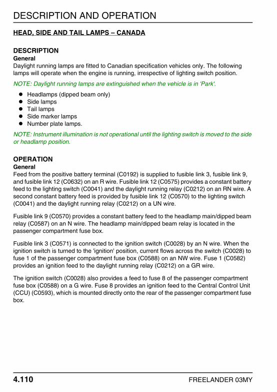
DESCRIPTION AND OPERATION
4.110 FREELANDER 03MY
HEAD, SIDE AND TAIL LAMPS – CANADA
DESCRIPTIONGeneralDaylight running lamps are fitted to Canadian specification vehicles only. The following lamps will operate when the engine is running, irrespective of lighting switch position.
NOTE: Daylight running lamps are extinguished when the vehicle is in 'Park'.
Headlamps (dipped beam only)Side lampsTail lampsSide marker lampsNumber plate lamps.
NOTE: Instrument illumination is not operational until the lighting switch is moved to the side or headlamp position.
OPERATIONGeneralFeed from the positive battery terminal (C0192) is supplied to fusible link 3, fusible link 9, and fusible link 12 (C0632) on an R wire. Fusible link 12 (C0575) provides a constant battery feed to the lighting switch (C0041) and the daylight running relay (C0212) on an RN wire. A second constant battery feed is provided by fusible link 12 (C0570) to the lighting switch (C0041) and the daylight running relay (C0212) on a UN wire.
Fusible link 9 (C0570) provides a constant battery feed to the headlamp main/dipped beam relay (C0587) on an N wire. The headlamp main/dipped beam relay is located in the passenger compartment fuse box.
Fusible link 3 (C0571) is connected to the ignition switch (C0028) by an N wire. When the ignition switch is turned to the 'ignition' position, current flows across the switch (C0028) to fuse 1 of the passenger compartment fuse box (C0588) on an NW wire. Fuse 1 (C0582) provides an ignition feed to the daylight running relay (C0212) on a GR wire.
The ignition switch (C0028) also provides a feed to fuse 8 of the passenger compartment fuse box (C0588) on a G wire. Fuse 8 provides an ignition feed to the Central Control Unit (CCU) (C0593), which is mounted directly onto the rear of the passenger compartment fuse box.

DESCRIPTION AND OPERATION
FREELANDER 03MY 4.111
Side LampsWhen the lighting switch is turned to the side lamp position, current flows across the switch (C0041) to the daylight running relay (C0212) on an RW wire. Current flows through the daylight running relay (C0212) to fuse 16 and fuse 28 of the passenger compartment fuse box (C0587) on an R wire. Fuse 16 (C0582) provides a feed to the following on RO wires:
The RH side lamp (C0011).The RH front side marker lamp (C0916).
Fuse 16 (C0583) also provides a feed to the following on RO wires:
The RH tail lamp (C0125).The RH rear side marker lamp (C0918).The rear number plate lamp (C0138).The trailer pick-up (C0499).
All are earthed on B wires except the trailer pick-up, which is earthed on a W then B wire.
Fuse 28 (C0581) provides a feed to the following on RB wires:
The LH side lamp (C0009).The LH front side marker lamp (C0917).
Fuse 28 (C0583) also provides a feed to the following on RB wires:
The LH tail lamp (C0121).The LH rear side marker lamp (C0919).The trailer pick-up (C0499).
All are earthed on B wires except the trailer pick-up, which is earthed on a W then B wire.
HeadlampsDipped BeamWhen the lighting switch is turned to the headlamp position, current flows across the switch (C0041) to the daylight running relay (C0212) on a UG wire. Current flows through the relay (C0212) to fuse 24 and fuse 25 of the passenger compartment fuse box (C0587) on a UO wire. Fuse 25 (C0582) provides a feed to the RH dipped beam bulb (C0011) on a UB wire. Fuse 24 (C0581) provides a feed to the LH dipped beam bulb (C0009) on a UK wire. Both are earthed on B wires.
Main BeamWhen the lighting switch is turned to the headlamp position, and pulled back to the main beam position, current flows across the switch (C0041) to the main/dipped beam relay coil (C0587) on a UW wire. The main/dipped beam relay coil is located within the passenger compartment fuse box (C0587) and is earthed on a B wire.

DESCRIPTION AND OPERATION
4.112 FREELANDER 03MY
The energised main/dipped beam relay allows a feed from fusible link 9 of the engine compartment fuse box (C0570) to provide a feed to fuse 18 and fuse 20 of the passenger compartment fuse box. Fuse 18 (C0584) provides a feed to the RH headlamp main beam bulb (C0011) on a UG wire. Fuse 18 (C0589) also provides a feed to the warning lamp located within the instrument pack (C0233) on a UG wire. Both are earthed on B wires.
Fuse 20 (C0587) provides a feed to the RH main beam bulb (C0009) on a US wire. The bulb (C0009) is earthed on a B wire.
Headlamp FlashWhen the LH column switch is pulled back (but not past) spring pressure, the headlamps operate in exactly the same way as described in the 'Main Beam' section until the switch is released.
CCUWhen the lighting switch is turned to the main beam position, current flows across the switch (C0041) to the CCU (C0428) on an OU wire. The CCU also monitors the condition of the driver door switch (C0441) on a PS then PW wire, and the ignition switch. If the driver door switch is closed and the ignition switch in the 'off' position, the CCU will power its integral 2 KHz sounder.
For more information on the driver door switch, refer to the Anti-theft Alarm and Central Door Locking (CDL) section of this manual. + ANTI-THEFT ALARM AND CENTRAL DOOR LOCKING (CDL).
Daylight Running LampsThe daylight running lamps will be operational if the following conditions are met:
The ignition switch is in the 'ignition' position.The engine is running.The automatic transmission isn't in 'Park'.The lighting switch isn't in the 'Headlamp' position.
The CCU (C0593) is provided an ignition feed via fuse 8 of the passenger compartment fuse box, and registers if the engine is running via the oil pressure switch. The CCU (C0592) provides a feed to the oil pressure switch (C0187) on a WN wire. The oil pressure switch contacts are closed when there is no oil pressure. When the engine is started, the rise in oil pressure causes the switch contacts to open.
If 'Park' is selected, the automatic transmission selector (C0244) provides a feed to the CCU (C0593) on a KO wire. For more information on automatic transmission operation, refer to the Electronic Automatic Transmission (EAT) section of this manual. + ELECTRONIC AUTOMATIC TRANSMISSION (EAT).

DESCRIPTION AND OPERATION
FREELANDER 03MY 4.113
The CCU (C0428) monitors the condition of the lighting switch (C0041) via a OU wire. A feed will only be provided to the CCU when the lighting switch is turned to the 'Headlamp' position.
If all of these conditions are met, the CCU (C0593) provides an earth path for the daylight running relay (C0212) on an RG wire. This allows a battery feed from fusible link 12 of the engine compartment fuse box (C0570) to flow through the relay (C0212) and power the headlamp dipped beam bulbs as described previously.

DESCRIPTION AND OPERATION
4.114 FREELANDER 03MY
FOG LAMPS
DESCRIPTIONGeneralNAS vehicles incorporate the rear fog lamps within the tail lamp assemblies, where they also double as brake lamps. For more information on brake lamp operation, refer to the Brake and Reverse Lamps section of this manual. + BRAKE AND REVERSE LAMPS.
All other vehicles have the fog lamps located on either side of the rear bumper, where they operate in the normal manner. Both systems are controlled by the Central Control Unit (CCU). The rear fog lamps will only operate if:
The ignition switch is turned to the 'ignition' position.The lighting switch is in the side or headlamp position.The non-latching switch mounted adjacent the instrument pack is pressed.
A warning lamp located in the instrument pack will illuminate when the fog lamps are operational.
OPERATIONGeneralFeed from the positive battery terminal (C0192) is supplied to fusible link 3, fusible link 9, and fusible link 12 of the engine compartment fuse box (C0192) on an R wire. Fusible link 9 (C0570) provides a constant battery feed to fuse 22 of the passenger compartment fuse box (C0587) on an N wire. Fuse 22 is connected to the rear fog lamp relay, which is also located in the passenger compartment fuse box.
Fusible link 3 (C0571) is connected to the ignition switch (C0028) by an N wire. When the ignition switch is turned to the 'ignition' position, current flows across the switch (C0028) to the rear fog lamp relay and fuse 8 of the passenger compartment fuse box (C0588) on a G wire. Fuse 8 provides an ignition feed to the Central Control Unit (CCU) (C0593), which is mounted directly onto the rear of the passenger compartment fuse box.
The earth path for the fog lamp relay coil is controlled by the CCU (C0593). The CCU (C0592) monitors the condition of the rear fog lamp switch (C0064) by providing a feed via the passenger compartment fuse box (C0589) on a RY wire. When the switch is pressed, a momentary earth path is created on a B wire.
The CCU also monitors the condition of the lighting switch. Fusible link 12 (C0570) provides a constant battery feed to the lighting switch (C0041) on a UN wire. When the lighting switch is turned to the side or headlamp position, current flows across the switch (C0041) to the CCU (C0428) on an OU wire. The CCU will now energise the rear fog lamp relay.

DESCRIPTION AND OPERATION
FREELANDER 03MY 4.115
The energised rear fog lamp relay (C0583) provides a feed to both the LH fog lamp (C0490 on NAS vehicles, C0515 on all other vehicles), and the RH fog lamp (C0489 on NAS vehicles, C0512 on all other vehicles) on RY wires. The relay also provides a feed to the trailer pick-up (C0499) on a RY then U wire. The fog lamps are earthed on B wires.
The energised rear fog lamp relay (C0589) also provides a feed to the instrument pack warning lamp (C0230) on a UY wire. The warning lamp (C0233) is earthed on a B wire.

DESCRIPTION AND OPERATION
4.116 FREELANDER 03MY
DIRECTION INDICATOR/HAZARD WARNING LAMPS
DESCRIPTIONGeneralThe direction indicator lamps are controlled via the LH column switch. The lamps will only operate when the ignition switch is in the 'ignition' position.
The hazard warning lamps are switched on and off by pressing the hazard warning switch mounted on the centre console. Hazard warning lamp operation is not dependant upon ignition switch position.
OPERATIONDirection Indicator LampsFeed from the positive battery terminal (C0192) is supplied to fusible link 3 of the engine compartment fuse box (C0632) on an R wire. Fusible link 3 (C0571) is connected to the ignition switch (C0028) by an N wire. When the ignition switch is turned to the 'ignition' position, current flows across the switch (C0028) to fuse 8 of the passenger compartment fuse box (C0588) on a G wire. Fuse 8 (C0580) provides an ignition feed to the hazard warning switch (C0096) on a G wire. Current flows across the switch (C0096) to the flasher unit (C0580) on an LGK wire. The flasher unit is located in the passenger compartment fuse box and is earthed (C0587) on a B wire. The energised flasher unit (C0580) provides a feed to the indicator switch (C0036) on a LGN wire.
LH TurnWhen the direction indicator switch is moved to the LH turn position, current flows across the switch (C0036) to the following:
The LH front direction indicator lamp (C0009) on a GR wire.The LH side repeater (C0013) on a GR wire.The LH rear direction indicator lamp (C0121) on a GR wire.The instrument pack (C0233) on a GR wire.The trailer pick-up (C0499) on a GR then Y wire.
All are earthed on B wires, except the trailer pick-up (W then B wire).

DESCRIPTION AND OPERATION
FREELANDER 03MY 4.117
RH TurnWhen the direction indicator switch is moved to the RH turn position, current flows across the switch (C0036) to the following:
The RH front direction indicator lamp (C0011) on a GW wire.The RH side repeater (C0012) on a GW wire.The RH rear direction indicator lamp (C0125) on a GW wire.The instrument pack (C0233) on a GW wire.The trailer pick-up (C0499) on a GW then G wire.
All are earthed on B wires, except the trailer pick-up (W then B wire).
Hazard Warning LampsFeed from the positive battery terminal (C0192) is supplied to fusible link 4 and fuse 7 of the engine compartment fuse box (C0632) on an R wire. Fusible link 4 (C0574) provides a constant battery feed to the Central Control Unit (CCU) (C0593) and fuse 14 of the passenger compartment fuse box (C0587) on an NW wire. Fuse 14 (C0589) is connected to the hazard warning lamp housed within the instrument pack (C0230) by a P wire. Illumination of the hazard warning lamp (C0233) is controlled by the hazard warning switch (C0096) on an SY wire.
Fuse 7 of the engine compartment fuse box (C0576) provides a constant battery feed to the hazard warning switch (C0096) on an NO wire. When the hazard warning switch is pressed, current flows across the switch (C0096) to the flasher unit (C0580) on an LGK wire. The flasher unit (C0587) is earthed on a B wire. The energised flasher unit (C0580) returns a feed back to the hazard warning switch (C0096) on an LGN wire. The hazard warning switch (C0096) is now able to provide feeds to both the LH and RH direction indicator circuits simultaneously on GR and GW wires respectively.
Fuse 7 of the engine compartment fuse box (C0576) also provides a constant battery feed to the hazard warning relay (C0581) on an NO wire. The earth path for the hazard warning relay is controlled by the CCU (C0593). For more details on hazard warning relay and CCU operation, refer to the Electrics section of the System Description and Operation Workshop manual, and the Anti-theft Alarm and Central Door Locking (CDL) section of this manual. + ANTI-THEFT ALARM AND CENTRAL DOOR LOCKING (CDL).

DESCRIPTION AND OPERATION
4.118 FREELANDER 03MY
INTERIOR LAMPS
DESCRIPTION3 DoorThe interior lamp is mounted in the centre of the headlining, and is controlled by the Central Control Unit (CCU) via a three position switch. With the switch in the centre position, the lamp will illuminate as soon as either door is opened. The interior lamp will fade out when any of the following occur:
Approximately 15 seconds after the last door is closed.When the ignition switch is turned to the 'ignition' position.When the vehicle is locked using either the remote handset or the key.After approximately 10 minutes if a door is left open.
With the switch in the forward 'ON' position, the lamp will remain illuminated irrespective of door status. With the switch in the rear 'OFF' position, the lamp will remain extinguished irrespective of door status.
Additional interior illumination is provided by a glove box lamp, and a load space lamp. The load space lamp will illuminate when the tail door is opened.
5 DoorThe front and rear interior lamps are mounted in the headlining, and are controlled by the Central Control Unit (CCU). Both interior lamps will illuminate when any door is opened. The lamps will fade out when any of the following occur:
Approximately 15 seconds after the last door is closed.When the ignition switch is turned to the 'ignition' position.When the vehicle is locked using either the remote handset or the key.After approximately 10 minutes if a door is left open.
The front interior lamp can also be switched on and off manually by pressing the central switch mounted on the lamp unit. Also incorporated into the front interior lamp unit are two map reading lamps. These can be switched on and off by pressing the appropriate switch on either side of the lamp unit. The rear interior lamp can also be switched on and off manually, by pressing the switch mounted on the rear lamp assembly.
Additional interior illumination is provided by a glove box lamp, and a load space lamp. The load space lamp will illuminate when the tail door is opened.

DESCRIPTION AND OPERATION
FREELANDER 03MY 4.119
OPERATIONGeneralFeed from the positive battery terminal (C0192) is supplied to fusible link 3, fusible link 4 and fusible link 12 of the engine compartment fuse box (C0632) on an R wire. Fusible link 12 (C0575) provides a constant battery feed to the lighting switch (C0041) on an RN wire. Fusible link 4 (C0574) provides a constant battery feed to fuse 14 of the passenger compartment fuse box (C0587) on an NW wire.
Fusible link 3 (C0571) is connected to the ignition switch (C0028) by an N wire. When the ignition switch is turned to the 'ignition' position, current flows across the switch (C0028) to fuse 8 of the passenger compartment fuse box (C0588) on a G wire. Fuse 8 provides an ignition feed to the Central Control Unit (CCU) (C0593), which is mounted directly to the rear of the passenger compartment fuse box.
Central Control Unit (CCU)The CCU monitors the condition of the door switches as follows:
The driver door switch (C0441) on a PS then PW wire.The front passenger door switch (C0441) on a PW wire.The LH rear passenger door switch (C0442) on a PW wire (5 door vehicles only).The RH rear passenger door switch (C0442) on a PW wire (5 door vehicles only).
NOTE: Both front door switches and both rear door switches have the same connector numbers as they utilise the same harness's.
All the above are normally open switches. If a door is opened, the switch contacts close and an earth path is created. When the CCU senses an earth path, it illuminates the interior lamp(s). All the above are earthed on B wires.
The CCU (C0428) also monitors the condition of the tail door switch (C0616) on a BO wire. When the tail door is opened, an earth path is created. The CCU will now illuminate the load space lamp (see 'Load Space Lamp').
For more information on CCU operation, refer to the Control Units section of the System Description and Operation Workshop manual.

DESCRIPTION AND OPERATION
4.120 FREELANDER 03MY
Illumination RelayVehicles fitted with an instrument dimmer switch are also fitted with an illumination relay. Fuse 14 of the passenger compartment fuse box (C0589) provides a constant battery feed to the illumination relay (C1976) on a pair of P wires. The earth path for the relay coil (C1976) is controlled by the CCU (C0592) on a BR wire.
The CCU (C0593) provides an earth path for the relay coil when it receives a 'key in' signal from the transponder coil (C0049) on a PW wire. The energised illumination relay (C1976) provides a feed to the automatic transmission selector (C0244) on an NR wire.
NOTE: If an instrument dimmer is not fitted, the feed to the automatic transmission selector (C0244) is provided by fuse 4 of the engine compartment fuse box via header 286.
For more information on instrument dimmer operation, refer to the Interior Illumination section of this manual. + INTERIOR ILLUMINATION.
Interior Lamp(s)3 DoorFuse 14 of the passenger compartment fuse box (C0580) provides a constant battery feed to the interior lamp (C0357) on a P wire. When the interior lamp switch is in the normal (central) position, the earth path for the lamp (C0357) is controlled by the CCU (C0593) via the passenger compartment fuse box (C0580) on a PW wire. The CCU will illuminate the interior lamp if it senses any of the doors are open (see 'Central Control Unit – CCU').
When the switch is moved to the 'ON' position, current flows across the bulb to earth via the lamp fixings. This results in the lamp being illuminated irrespective of the condition of the door switches.
When the switch is moved to the 'OFF' position, the circuit is broken. This results in the lamp being extinguished irrespective of the condition of the door switches.
5 DoorFuse 14 of the passenger compartment fuse box (C0580) provides a constant battery feed to the front interior lamp (C0355) on a P wire. When the interior lamp switch is in the normal position, the earth path for the lamp (C0355) is controlled by the CCU (C0593) via the passenger compartment fuse box (C0580) on a PW wire. The CCU will illuminate the interior lamp if it senses any of the doors are open (see 'Central Control Unit – CCU').
When the switch is pressed, current flows across the bulb (C0355) to earth on a B wire. This results in the lamp being illuminated irrespective of the condition of the door switches.

DESCRIPTION AND OPERATION
FREELANDER 03MY 4.121
Fuse 14 (C0580) also provides a constant battery feed to the rear interior lamp (C0356) on a P wire. When the interior lamp switch is in the normal position, the earth path for the lamp (C0356) is controlled by the CCU (C0593) via the passenger compartment fuse box (C0580) on a PW wire. The CCU will illuminate the interior lamp if it senses any of the doors are open (see 'Central Control Unit – CCU').
When the switch is pressed, current flows across the bulb (C0356) to earth on a B wire. This results in the lamp being illuminated irrespective of the condition of the door switches.
Map Reading Lamps (5 Door Vehicles Only)Fuse 14 of the passenger compartment fuse box (C0580) provides a constant battery feed to both the LH and RH map reading lamp switches (C0355) on a P wire. When either of the switches are pressed, current is able to flow across the switch to the map reading lamp bulb. Both bulbs are earthed via the lamp fixings.
Load Space LampFuse 14 of the passenger compartment fuse box (C0583) provides a constant battery feed to the load space lamp (C0119) on a P wire. The earth path for the load space lamp (C0120) is controlled by the CCU (C0593) via the passenger compartment fuse box (C0580) on a PW wire. The CCU will illuminate the interior lamp if it senses the tail door is open (see 'Central Control Unit – CCU').
Glove Box LampFusible link 12 of the engine compartment fuse box (C0575) provides a constant battery feed to the lighting switch (C0041) on an RN wire. When the lighting switch is turned to the side or headlamp position, current flows across the switch to fuse 16 of the passenger compartment fuse box (C0587) on an R wire. Fuse 16 (C0589) provides a feed to the glove box lamp (C0227) on an RO wire.
The earth path for the glove box lamp (C0235) is controlled by the glove box switch (C0238) on a BR wire. When the glove box is opened, the switch closes and an earth path is created via the passenger compartment fuse box (C0587) on a B wire.
Vanity MirrorsFuse 14 of the passenger compartment fuse box (C0580) provides a constant battery feed to the LH (C0760 on 3 door vehicles, C0737 on 5 door vehicles) and RH (C0736) vanity mirror lamps on P wires. The lamps are earthed on B wires.

DESCRIPTION AND OPERATION
4.122 FREELANDER 03MY
INTERIOR ILLUMINATION
DESCRIPTIONGeneralInterior illumination provides background lighting for the instrument pack and control switch graphics. Interior illumination operates when the lighting switch is turned to the side or headlamp position, irrespective of ignition switch position.
OPERATIONGeneralFeed from the positive battery terminal (C0192) is supplied to fusible link 12 of the engine compartment fuse box (C0632) on an R wire. Fusible link 12 (C0575) is connected to the lighting switch (C0041) by an RN wire. When the lighting switch is turned to the side or headlamp position, current flows across the switch (C0041) to fuse 16 of the passenger compartment fuse box (C0587) on an R wire.
Fuse 16 (C0582) provides a feed to the following on RO wires:
The cruise control master switch (C0749).The hazard warning switch (C0096).The Heated Rear Window (HRW) switch (C0072).The front LH window switch (C0321).The front RH window switch (C0242).The Hill Descent Control (HDC) switch (C0878).The tail door window switch (C0354).The Central Door Locking (CDL) switch (C0328).The LH seat switch (C0249).The RH seat switch (C0250).The LH rear window switch (C0264) (5 door vehicles only).The RH rear window switch (C0263) (5 door vehicles only).The sunroof switch (C0363).The cigar lighter (C0074).The radio/cassette player (C0098).The radio/cassette player (C0921) (NAS vehicles only).The heater controls (C0051).The air conditioning (a/c) switch pack (C0275).The fresh/recirculated air switch (C0750).The Heated Front Screen (HFS) switch (C0131).
All the above are earthed on B wires.

DESCRIPTION AND OPERATION
FREELANDER 03MY 4.123
Fuse 16 (C0589) also provides a feed to the following on RO wires:
The instrument pack (C0233).The rear fog lamp switch (C0064).The radio remote display/clock (C0241).The rear screen washer switch (C0073).The rear screen wiper switch (C0079).
All the above are earthed on B wires.
Instrument Dimmer (Canadian Vehicles Only)The instrument dimmer is a rotary potentiometer mounted on the fascia below the instrument pack. When the lighting switch is turned to the side or headlamp position, current flows across the switch (C0041) to fuse C (C1875) on an RW wire. Fuse C (C1875) is connected to the instrument dimmer (C0201) by an RB wire. The dimmer (C0201) provides a feed to all the switches and controls mentioned previously on RO wires.
The switch (C0201) also contains a tell-tale LED, which is earthed on a B wire.

DESCRIPTION AND OPERATION
4.124 FREELANDER 03MY
INSTRUMENTS
DESCRIPTIONGeneralThe instrument pack is a totally electronic controlled device receiving electrical signals from sender units, and CAN messages from the Engine Control Module (ECM), the ABS ECU, the Electronic Automatic Transmission Electronic Control Unit (EAT ECU) and the cruise control interface unit (Td4 vehicles only). The instrument pack transposes these via a microprocessor into analogue gauge read out and warning lamp illumination.
The warning lamps illuminate in one of four colours, which indicate the level of importance of the warning as follows:
Red = Warning.Yellow = Caution.Green = System operative.Blue = Headlamp main beam operative.
For a detailed description of the instrument pack, refer to the Instruments section of the System Description and Operation Workshop manual.
OPERATIONGeneralFeed from the positive battery terminal (C0192) is supplied to the following (C0632) on an R wire:
Fuse 7Fusible link 12Fusible link 9Fusible link 4Fusible link 3
Fuse 7 (C0576) provides a constant battery feed to the hazard warning relay located in the passenger compartment fuse box (C0581) on an NO wire.
Fusible link 12 (C0575) provides a constant battery feed to the lighting switch (C0041) on an RN wire.
Fusible link 9 (C0570) is connected to the main/dipped beam relay and fuse 22 of the passenger compartment fuse box (C0587) by an N wire. Fuse 22 provides a constant battery feed to the rear fog lamp relay, which is also located in the passenger compartment fuse box.

DESCRIPTION AND OPERATION
FREELANDER 03MY 4.125
Fusible link 4 (C0574) is connected to fuse 14 of the passenger compartment fuse box (C0587) by an NW wire. Fuse 14 (C0589) provides a constant battery feed to the instrument pack ECU (C0230) on a P wire.
Fusible link 3 (C0571) is connected to the ignition switch (C0028) by an N wire. When the ignition switch is turned to the 'ignition' position, current flows across the switch (C0028) to fuse 8 of the passenger compartment fuse box (C0588) on a G wire. Fuse 8 (C0589) provides an ignition feed to the instrument pack (C0233) on a G wire.

DESCRIPTION AND OPERATION
4.126 FREELANDER 03MY
The warning lamps contained within the instrument operate as follows:
The LH direction indicator warning lamp (C0233) receives a feed from the hazard warning lamp relay (C0589) on a GR wire. The lamp is earthed on a B wire.The RH direction indicator warning lamp (C0233) receives a feed from the hazard warning lamp relay (C0589) on a GW wire. The lamp is earthed on a B wire.The main beam warning lamp (C0233) receives a feed from the main/dipped beam relay via fuse 18 of the passenger compartment fuse box (C0589) on a UG wire. The lamp is earthed on a B wire.The rear fog warning lamp (C0230) receives a feed from the rear fog lamp relay (C0589) on a UY wire. The lamp is earthed on a B wire.The glow plug warning lamp receives a constant battery feed from fuse 14 of the passenger compartment fuse box (C0589) on a P wire. Illumination of the lamp is controlled by the Engine Control Module (ECM) (C0331) via the CAN-BUS on YN (Low) and YB (High) wires. This signal is relayed via the ABS ECU (C0501).The seat belt warning lamp receives an ignition feed from fuse 8 of the passenger compartment fuse box (C0589) on a G wire. Illumination of the lamp is controlled by the Central Control Unit (CCU) (C0593) via the passenger compartment fuse box (C0589) on an RP wire.
NOTE: The seat belt warning lamp is not operational in all markets.The SRS warning lamp receives an ignition feed from fuse 8 of the passenger compartment fuse box (C0589) on a G wire. Illumination of the lamp is controlled by the airbag DCU (C0256) on a YR wire.The ABS warning lamp receives a constant battery feed from fuse 14 of the passenger compartment fuse box (C0589) on a P wire. Illumination of the lamp is controlled by the ABS ECU (C0501) via the CAN-BUS on YN (Low) and YB (High) wires.The door open warning lamp receives an ignition feed from fuse 8 of the passenger compartment fuse box (C0589) on a G wire. Illumination of the lamp is controlled by the CCU (C0593) via the passenger compartment fuse box (C0589) on a PB wire.The hazard warning lamp (C0230) receives a constant battery feed from fuse 14 of the passenger compartment fuse box (C0589) on a P wire. Illumination of the lamp is controlled by the hazard warning switch (C0096) on a SY wire.The Hill Descent Control (HDC) warning lamp receives a constant battery feed from fuse 14 of the passenger compartment fuse box (C0589) on a P wire. Illumination of the lamp is controlled by the ABS ECU (C0501) via the CAN-BUS on YN (Low) and YB (High) wires.The Hill Descent Control (HDC) information lamp receives a constant battery feed from fuse 14 of the passenger compartment fuse box (C0589) on a P wire. Illumination of the lamp is controlled by the ABS ECU (C0501) via the CAN-BUS on YN (Low) and YB (High) wires.
DESCRIPTION AND OPERATION
FREELANDER 03MY 4.127
The handbrake/low brake fluid warning lamp receives a constant battery feed from fuse 14 of the passenger compartment fuse box (C0589) on a P wire. Illumination of the lamp is controlled by the handbrake switch (C0091) on a BW wire. When the handbrake is applied, the switch contacts close and an earth path is created, illuminating the lamp. Illumination of the lamp is also controlled by the ABS ECU (C0501) via the CAN BUS on YN (Low) and YB (High) wires. If the warning lamp is illuminated while the handbrake is released, urgent attention is required to the braking system.The low oil pressure warning lamp receives an ignition feed from fuse 8 of the passenger compartment fuse box (C0589) on a G wire. Illumination of the lamp is controlled by the oil pressure switch (C0187) on a WN wire (WN then NG on Td4 vehicles).The ignition/no charge warning lamp receives an ignition feed from fuse 8 of the passenger compartment fuse box (C0589) on a G wire. Illumination of the lamp is controlled by the ECM (C0331) on Td4 vehicles, and the alternator (C0053) on K1.8 and KV6 vehicles.The anti-theft alarm LED receives a constant battery feed from fuse 14 of the passenger compartment fuse box (C0589) on a P wire. Illumination of the lamp is controlled by the CCU (C0592) via the passenger compartment fuse box (C0589) on a UK wire.The overspeed warning lamp receives a constant battery feed from fuse 14 of the passenger compartment fuse box (C0589) on a P wire. Illumination of the lamp is controlled by the ABS ECU (C0501) via the CAN-BUS on YN (Low) and YB (High) wires.
NOTE: The overspeed warning lamp is not operational in all markets.The cruise control warning lamp receives a constant battery feed from fuse 14 of the passenger compartment fuse box (C0589) on a P wire. On KV6 vehicles, illumination of the warning lamp is controlled by the cruise control ECU (C0239) on a WU wire. On Td4 vehicles, illumination of the warning lamp is controlled by the cruise control interface unit (C1959) via the CAN-BUS on YN (Low) and YB (High) wires.
NOTE: The list of CAN-BUS connections is by no means exhaustive. For more details, refer to the 'Communication Databuses' and 'Instruments' sections of the System Description and Operation Workshop manual.

DESCRIPTION AND OPERATION
4.128 FREELANDER 03MY
SpeedometerThe speedometer is driven by a CAN message from the Engine Control Module (ECM) on YN (Low) and YB (High) wires. For more information on speedometer operation, refer to the Instruments section of the System Description and Operation Workshop manual.
TachometerThe tachometer is driven by a CAN message from the Engine Control Module (ECM) on YN (Low) and YB (High) wires. For more information on tachometer operation, refer to the Instruments section of the System Description and Operation Workshop manual.
Engine Coolant Temperature GaugeThe Engine Coolant Temperature (ECT) gauge is driven by a CAN message from the Engine Control Module (ECM) on YN (Low) and YB (High) wires. For more information on ECT gauge operation, refer to the Instruments section of the System Description and Operation Workshop manual.
Fuel GaugeThe instrument pack (C0230) provides a feed to the fuel tank sender (C0114) on a GB wire. The sender is located within the fuel tank and is earthed on a B wire. The sender is a float operated rotary potentiometer, which provides a variable resistance to earth for the output from the instrument pack.
For more information on fuel gauge operation, refer to the Instruments section of the System Description and Operation Workshop manual.

DESCRIPTION AND OPERATION
FREELANDER 03MY 4.129
HORNS
DESCRIPTIONGeneralTwo vehicle horns are fitted, one below each headlamp on either side of the engine bay. One horn emits a high tone, the other a low tone. The horns are operated by pressing either of the two buttons located on the steering wheel.
The horn circuit is fed directly from the battery and operates independently of the ignition circuits. The horns are also used as an audible warning if the anti-theft alarm system is triggered. For more information on anti-theft alarm operation, refer to the Anti-theft Alarm and Central Door Locking (CDL) section of this manual. + ANTI-THEFT ALARM AND CENTRAL DOOR LOCKING (CDL).
OPERATIONHornsFeed from the positive battery terminal (C0192) is supplied to fusible link 4, fuse 6, and the horn relay coil (C0632) on an R wire. All are located in the engine compartment fuse box. The horn relay coil (C0576) is connected to the horn switches (C1254) via the rotary coupler (C0082) by a PY then P wire. The horn switches are normally open switches. When either of the horn switches are depressed, the switch contacts close and an earth path is created via the rotary coupler (C0082) on a B wire.
The horn relay (C0576) is now energised, and is able to provide a feed from fuse 6 to the LH horn (C0003) on a PB wire. The horn relay (C0570) also provides a feed to the RH horn (C0004) on a PB wire. Both horns are earthed on B wires.
Alarm TriggerFusible link 4 (C0574) provides a constant battery feed to the Central Control Unit (CCU) (C0593) via the passenger compartment fuse box (C0587) on an NW wire. If the alarm is triggered, the CCU (C0430) provides an earth path for the relay coil (C0576) on a PY wire. The horns relay is now able to provide a feed to the horns as described above.
By pulsing the earth path for the horn relay on and off, the CCU is able to control operation of the horns. For more information on alarm operation, refer to the Anti-theft Alarm and Central Door Locking (CDL) section of this manual. + ANTI-THEFT ALARM AND CENTRAL DOOR LOCKING (CDL).

DESCRIPTION AND OPERATION
4.130 FREELANDER 03MY
REMOTE DISPLAY / CLOCK
DESCRIPTIONGeneralThe remote display/clock is mounted in the centre of the fascia. The time displayed on the clock can be adjusted using the 'H' and 'M' buttons mounted in the clock bezel. The clock will also display radio/cassette information. For more details on audio system operation, refer to the relevant Audio System section of this manual. + AUDIO SYSTEM – LOW LINE. + AUDIO SYSTEM – MID LINE. + NAVIGATION SYSTEM.
OPERATIONGeneralFeed from the positive battery terminal (C0192) is supplied to fusible link 1, fusible link 4, and fusible link 12 of the engine compartment fuse box (C0632) on an R wire. Fusible link 4 (C0574) is connected to fuse 14 of the passenger compartment fuse box (C0587) by an NW wire. Fuse 14 (C0589) provides a constant battery feed to the remote display/clock (C0241) on a P wire. The remote display/clock (C0241) is earthed on a B wire.
Fusible link 1 is connected in series with fusible link 2, which is also located in the engine compartment fuse box. Fusible link 2 (C0571) provides a constant battery feed to the ignition switch (C0028) on an NR wire. When the ignition switch is turned to the 'ignition' position, current flows across the switch (C0028) to fuse 11 of the passenger compartment fuse box (C0588) on a PS wire. Fuse 11 (C0580) provides an ignition feed to the remote display/clock (C0241) on a LGW wire. When the remote display/clock receives this feed, it will illuminate.
Fusible link 12 (C0575) provides a constant battery feed to the lighting switch (C0041) on an RN wire. When the lighting switch is turned to the side or headlamp position, current flows across the switch (C0041) to fuse 16 of the passenger compartment fuse box (C0587) on an R wire. Fuse 16 (C0589) is connected to the remote/display/clock by an RO wire. When the remote display/clock receives this feed, it dims its illumination.
DESCRIPTION AND OPERATION
FREELANDER 03MY 4.131
CIGAR LIGHTER
DESCRIPTIONGeneralThe cigar lighter is located in the centre console, and will only operate when the ignition switch is in the 'auxiliary' or 'ignition' position. When the cigar lighter element is pushed into its holder, power is automatically switched through its locking clips to the heater coil. As current passes through the heating coil, the element will heat up to the point where the locking clips expand and release the cigar lighter element.
OPERATIONGeneralFeed from the positive battery terminal (C0192) is supplied to fusible link 1 of the passenger compartment fuse box (C0632) on an R wire. Fusible link 1 is connected in series with fusible link 2, which is also located in the engine compartment fuse box.
Fusible link 2 (C0571) is connected to the ignition switch (C0028) by an NR wire. When the ignition switch is turned to the 'auxiliary' position, current flows across the switch (C0028) to fuse 10 of the passenger compartment fuse box (C0588) on a PS wire.
Fuse 10 (C0585) provides a feed to the cigar lighter (C0089) on a PR wire. When the cigar lighter element is pushed into the cigar lighter, an earth path is created (C0089) on a B wire. When the element reaches the correct temperature and is ejected, the circuit is broken.

DESCRIPTION AND OPERATION
4.132 FREELANDER 03MY
ACCESSORY SOCKET
DESCRIPTIONGeneralThe accessory socket is located at the rear of the centre console. It supplies battery voltage to any approved Land Rover accessory when the ignition switch is in either the 'auxiliary' or 'ignition' position.
CAUTION: The cigar lighter should NOT be used for accessory power or damage may result.
OPERATIONGeneralFeed from the positive battery terminal (C0192) is supplied to fusible link 1 and fusible link 4 of the engine compartment fuse box (C0632) on an R wire. Fusible link 4 (C0574) is connected to fuse 13 of the passenger compartment fuse box (C0587) by an NW wire.
Fusible link 1 is connected in series with fusible link 2, which is also located in the engine compartment fuse box. Fusible link 2 (C0571) is connected to the ignition switch (C0028) by an NR wire. When the ignition switch is turned to the 'auxiliary' position, current flows across the switch (C0028) to the accessory socket relay (C0588) on a PS wire. The accessory socket relay is located in the passenger compartment fuse box, and is earthed (C0587) on a B wire.
The energised accessory socket relay allows a feed from fuse 13 to flow across the relay switch contacts (C0586) to the accessory socket (C0350) on a PN wire. The accessory socket (C0350) is earthed on a B wire.

DESCRIPTION AND OPERATION
FREELANDER 03MY 4.133
AUDIO SYSTEM – LOW LINE
DESCRIPTIONGeneralThe low line audio system features a centre console mounted radio/cassette player, which will operate when the ignition switch is in the 'auxiliary' position.
Five door vehicles have a mid-range speaker mounted behind each front and rear door trim casing , in addition to high range speakers mounted behind the door mirror trim casings. Four door vehicles have mid-range speakers mounted behind each front door trim casing, and both rear passenger compartment trim casings.
OPERATIONGeneralFeed from the positive battery terminal (C0192) is supplied to fusible link 1 and fusible link 4 of the engine compartment fuse box (C0632) on an R wire. Fusible link 4 (C0574) is connected to fuse 9 of the passenger compartment fuse box (C0587) by an NW wire.
Fuse 9 (C0585) provides a constant battery feed to the head unit (C0098) on a P wire. The head unit uses this feed to power its memory circuits, and is earthed (C0098) on a B wire. Fuse 9 (C0585) also provides a feed to the CD autochanger (if fitted) (C0941) on a P wire.
Fusible link 1 is connected in series with fusible link 2, which is also located in the engine compartment fuse box. Fusible link 2 (C0571) is connected to the ignition switch (C0028) by an NR wire. When the ignition switch is turned to the 'auxiliary' position, current flows across the switch (C0028) to fuse 11 of the passenger compartment fuse box (C0588) on a PS wire. Fuse 11 (C0580) provides an auxiliary ignition feed to the head unit (C0098) on an LGW wire.

DESCRIPTION AND OPERATION
4.134 FREELANDER 03MY
SpeakersThe head unit (C0098) is connected to the speakers as follows:
NOTE: The LH front and RH front mid-range and high range speakers share the same connector numbers as they utilise the same door harness. The same is true of the LH and RH rear mid-range speakers.
A positive signal is provided by the head unit to the RH front mid-range speaker (C0369) on an OK wire. The RH front mid-range speaker (C0369) is provided a negative signal by the head unit (C0098) on an OB wire.A positive signal is provided by the head unit to the RH front high range speaker (C0531) on an OK wire. The RH front high range speaker (C0530) is provided a negative signal by the head unit (C0098) on an OB wire.A positive signal is provided by the head unit to the LH front mid-range speaker (C0369) on a YK then OK wire. The LH front mid-range speaker (C0369) is provided a negative signal by the head unit (C0098) on a YB then OB wire.A positive signal is provided by the head unit to the LH front high range speaker (C0531) on a YK then OK wire. The LH front high range speaker (C0680) is provided a negative signal by the head unit (C0530) on a YB then OB wire.A positive signal is provided by the head unit to the RH rear mid-range speaker (C1577) on a UK wire. The RH rear mid-range speaker (C1577) is provided a negative signal by the head unit (C0098) on a UB wire.A positive signal is provided by the head unit to the LH rear mid-range speaker (C1577) on an SK then UK wire. The LH rear mid-range speaker (C1577) is provided a negative signal by the head unit (C0098) on an SB then UB wire.
NOTE: It is essential that all speakers are connected correctly. A speaker connected incorrectly will be out of phase with the remaining speakers, causing a deterioration of sound quality.
Remote Audio ControlsThe head unit (C0098) provides a feed via the rotary coupler (C0082) to the remote audio controls (C1254) on a BR wire. The remote audio controls contain a number of normally open switches and resistors. When either of the controls are moved, one of the switches closes and a voltage is returned to the head unit (C0098) on a BW wire. The value of the voltage returned to the head unit is dependent upon which way the controls are moved (and how many resistors are brought into the circuit). By measuring this returned voltage, the head unit determines which function has been requested.
CD AutochangerThe CD autochanger (C0941) is provided a constant battery feed via fuse 9 of the passenger compartment fuse box (C0585) on a P wire. The autochanger (C0941) is earthed on a B wire.

DESCRIPTION AND OPERATION
FREELANDER 03MY 4.135
The CD autochanger (C0941) provides the following signals to the head unit (C1354):
A LH speaker positive signal on a KB wire.A LH speaker negative signal on a BK wire.A RH speaker positive signal on a YB wire.A RH speaker negative signal on a BY wire.An earth on a B wire.
There is also a communications line between the CD autochanger (C0941) and head unit (C0098) on a WRY wire.

DESCRIPTION AND OPERATION
4.136 FREELANDER 03MY
AUDIO SYSTEM – MID LINE
DESCRIPTIONGeneralThe mid line audio system features a centre console mounted radio and a front loading single CD player, which will operate when the ignition switch is in the 'auxiliary' position. Some vehicles are also fitted with a power amplifier and sub-woofer. For more information on audio system features and functionality, refer to the In-Car Entertainment handbook.
NOTE: The supporting circuit diagram shows the mid-range audio system fitted with optional Harmon Kardon speakers. A system fitted with standard speakers will not have a power amplifier or rear high range speakers fitted. The connector numbers applied to the high range speakers differ between the two speaker systems. For more information, refer to the 'Speakers – Standard' and 'Speakers – Harmon Kardon' sections.
OPERATIONGeneralFeed from the positive battery terminal (C0192) is supplied to fusible link 1 and fusible link 4 of the engine compartment fuse box (C0632) on an R wire. Fusible link 4 (C0574) is connected to fuse 9 of the passenger compartment fuse box (C0587) by an NW wire. Fuse 9 (C0585) provides a constant battery feed to the head unit (C0921) on a P wire (P then PK if fitted with a power amplifier) and the power amplifier (C0491) on a P then PK wire.
Fusible link 1 is connected in series with fusible link 2, which is also located in the engine compartment fuse box. Fusible link 2 (C0571) is connected to the ignition switch (C0028) by an NR wire. When the ignition switch is turned to the 'auxiliary' position, current flows across the switch (C0028) to fuse 11 of the passenger compartment fuse box (C0588) on a PS wire. Fuse 11 (C0580) provides an auxiliary ignition feed to the head unit (C0921) on an LGW wire.
The head unit (C0921) and the power amplifier (C0491) are both earthed on B wires.

DESCRIPTION AND OPERATION
FREELANDER 03MY 4.137
Speakers – StandardThe head unit (C0092) is connected to the speakers as follows:
NOTE: The LH and RH speakers share the same connector numbers as they utilise the same door harness.
A positive signal is provided by the head unit to the RH front mid-range speaker (C0369) on an OK wire. The RH front mid-range speaker (C0369) is provided a negative signal by the head unit (C0092) on an OB wire.A positive signal is provided by the head unit to the RH front high range speaker (C0531) on an OK wire. The RH front high range speaker (C0530) is provided a negative signal by the head unit (C0092) on an OB wire.A positive signal is provided by the head unit to the LH front mid-range speaker (C0369) on a YK then OK wire. The LH front mid-range speaker (C0369) is provided a negative signal by the head unit (C0092) on a YB then OB wire.A positive signal is provided by the head unit to the LH front high range speaker (C0531) on a YK then OK wire. The LH front high range speaker (C0530) is provided a negative signal by the head unit (C0092) on an YB then OB wire.A positive signal is provided by the head unit to the RH rear mid-range speaker (C1577) on a UK wire. The RH rear mid-range speaker (C1577) is provided a negative signal by the head unit (C0092) on a UB wire.A positive signal is provided by the head unit to the LH rear mid-range speaker (C1577) on an SK then UK wire. The LH rear mid-range speaker (C1577) is provided a negative signal by the head unit (C0092) on an SB then UB wire.
NOTE: It is essential that all speakers are connected correctly. A speaker connected incorrectly will be out of phase with the remaining speakers, causing a deterioration of sound quality.

DESCRIPTION AND OPERATION
4.138 FREELANDER 03MY
Speakers – Harmon KardonThe head unit (C0092) is connected to the power amplifier (C0491) as follows:
A positive signal is provided by the head unit to the power amplifier on a BG wire. This signal is used by the power amplifier for the RH rear speakers.A negative signal is provided by the head unit to the power amplifier on a BO wire. This signal is used by the power amplifier for the RH rear speakers.A positive signal is provided by the head unit to the power amplifier on a BP wire. This signal is used by the power amplifier for the RH front speakers.A negative signal is provided by the head unit to the power amplifier on a BU wire. This signal is used by the power amplifier for the RH front speakers.A positive signal is provided by the head unit to the power amplifier on a BW wire. This signal is used by the power amplifier for the LH front speakers.A negative signal is provided by the head unit to the power amplifier on a BS wire. This signal is used by the power amplifier for the LH front speakers.A positive signal is provided by the head unit to the power amplifier on a BN wire. This signal is used by the power amplifier for the LH rear speakers.A negative signal is provided by the head unit to the power amplifier on a BR wire. This signal is used by the power amplifier for the LH rear speakers.
DESCRIPTION AND OPERATION
FREELANDER 03MY 4.139
The power amplifier (C0491) receives inputs from the head unit (C0092) and relays them to the speakers as follows:
NOTE: The LH and RH speakers share the same connector numbers as they utilise the same door harness.
A positive signal is provided by the power amplifier to the RH front mid-range speaker (C0369) on an OK wire. The RH front mid-range speaker (C0369) is provided a negative signal by the power amplifier (C0491) on an OB wire.A positive signal is provided by the power amplifier to the RH front high range speaker (C0680) on an OK wire. The RH front high range speaker (C0680) is provided a negative signal by the power amplifier (C0491) on an OB wire.A positive signal is provided by the power amplifier to the LH front mid-range speaker (C0369) on a YK then OK wire. The LH front mid-range speaker (C0369) is provided a negative signal by the power amplifier (C0491) on a YB then OB wire.A positive signal is provided by the power amplifier to the LH front high range speaker (C0680) on a YK then OK wire. The LH front high range speaker (C0680) is provided a negative signal by the power amplifier (C0491) on an YB then OB wire.A positive signal is provided by the power amplifier to the RH rear mid-range speaker (C1577) on a UK wire. The RH rear mid-range speaker (C1577) is provided a negative signal by the power amplifier (C0491) on a UB wire.A positive signal is provided by the power amplifier to the RH rear high range speaker (C0679) on a UK wire. The RH rear high range speaker (C0679) is provided a negative signal by the power amplifier (C0491) on a UB wire.A positive signal is provided by the power amplifier to the LH rear mid-range speaker (C1577) on an SK then UK wire. The LH rear mid-range speaker (C1577) is provided a negative signal by the power amplifier (C0491) on an SB then UB wire.A positive signal is provided by the power amplifier to the LH rear high range speaker (C0679) on an SK then UK wire. The LH rear high range speaker (C0679) is provided a negative signal by the power amplifier (C0491) on an SB then UB wire.
NOTE: It is essential that all speakers are connected correctly. A speaker connected incorrectly will be out of phase with the remaining speakers, causing a deterioration of sound quality.
Remote Audio ControlsThe head unit (C0921) provides a feed via the rotary coupler (C0082) to the remote audio controls (C1254) on a BR wire. The remote audio controls contain a number of normally open switches and resistors. When either of the controls are moved, one of the switches closes and a voltage is returned to the head unit (C0921) on a BW wire. The value of the voltage returned to the head unit is dependent upon which way the controls are moved (and how many resistors are brought into the circuit). By measuring this returned voltage, the head unit determines which function has been requested.

DESCRIPTION AND OPERATION
4.140 FREELANDER 03MY
NAVIGATION SYSTEM
DESCRIPTIONGeneralThe satellite navigation head unit is located in the centre console, and also incorporates a radio and a front loading single CD player. Some vehicles are also fitted with a CD autochanger.
The system operates when the ignition switch is turned to the 'auxiliary' position. For more information on audio system features and functionality, refer to the Audio and Navigation System handbook. For detailed information on satellite navigation operation, refer to the Navigation System section of the System Description and Operation Workshop manual.
NOTE: The supporting circuit diagram shows the Navigation system fitted with optional Harmon Kardon speakers. A system fitted with standard speakers will not have a power amplifier or rear high range speakers fitted. The connector numbers applied to the high range speakers differ between the two speaker systems. For more information, refer to the 'Speakers – Standard' and 'Speakers – Harmon Kardon' sections.
OPERATIONGeneralFeed from the positive battery terminal (C0192) is supplied to fusible link 1 and fusible link 4 of the engine compartment fuse box (C0632) on an R wire. Fusible link 4 (C0574) is connected to fuse 9 of the passenger compartment fuse box (C0587) by an NW wire. Fuse 9 (C0585) provides a constant battery feed to the following on P then PK wires:
The head unit (C0921)The CD autochanger (C0941)The power amplifier (C0491).
Fusible link 1 is connected in series with fusible link 2, which is also located in the engine compartment fuse box. Fusible link 2 (C0571) is connected to the ignition switch (C0028) by an NR wire. When the ignition switch is turned to the 'auxiliary' position, current flows across the switch (C0028) to fuse 11 of the passenger compartment fuse box (C0588) on a PS wire. Fuse 11 (C0580) provides an auxiliary ignition feed to the head unit (C0921) and the remote interface unit (C1897) on LGW wires.
The head unit (C0921), CD autochanger (C0941), power amplifier (C0491), and the remote interface unit (C1897) are all earthed on B wires.

DESCRIPTION AND OPERATION
FREELANDER 03MY 4.141
Speakers – Harmon KardonThe head unit (C0092) is connected to the power amplifier (C0491) as follows:
A positive signal is provided by the head unit to the power amplifier on a BG wire. This signal is used by the power amplifier for the RH rear speakers.A negative signal is provided by the head unit to the power amplifier on a BO wire. This signal is used by the power amplifier for the RH rear speakers.A positive signal is provided by the head unit to the power amplifier on a BP wire. This signal is used by the power amplifier for the RH front speakers.A negative signal is provided by the head unit to the power amplifier on a BU wire. This signal is used by the power amplifier for the RH front speakers.A positive signal is provided by the head unit to the power amplifier on a BW wire. This signal is used by the power amplifier for the LH front speakers.A negative signal is provided by the head unit to the power amplifier on a BS wire. This signal is used by the power amplifier for the LH front speakers.A positive signal is provided by the head unit to the power amplifier on a BN wire. This signal is used by the power amplifier for the LH rear speakers.A negative signal is provided by the head unit to the power amplifier on a BR wire. This signal is used by the power amplifier for the LH rear speakers.

DESCRIPTION AND OPERATION
4.142 FREELANDER 03MY
The power amplifier (C0491) receives inputs from the head unit (C0092) and relays them to the speakers as follows:
NOTE: The LH and RH speakers share the same connector numbers as they utilise the same door harness.
A positive signal is provided by the power amplifier to the RH front mid-range speaker (C0369) on an OK wire. The RH front mid-range speaker (C0369) is provided a negative signal by the power amplifier (C0491) on an OB wire.A positive signal is provided by the power amplifier to the RH front high range speaker (C0680) on an OK wire. The RH front high range speaker (C0680) is provided a negative signal by the power amplifier (C0491) on an OB wire.A positive signal is provided by the power amplifier to the LH front mid-range speaker (C0369) on a YK then OK wire. The LH front mid-range speaker (C0369) is provided a negative signal by the power amplifier (C0491) on a YB then OB wire.A positive signal is provided by the power amplifier to the LH front high range speaker (C0680) on a YK then OK wire. The LH front high range speaker (C0680) is provided a negative signal by the power amplifier (C0491) on an YB then OB wire.A positive signal is provided by the power amplifier to the RH rear mid-range speaker (C1577) on a UK wire. The RH rear mid-range speaker (C1577) is provided a negative signal by the power amplifier (C0491) on a UB wire.A positive signal is provided by the power amplifier to the RH rear high range speaker (C0679) on a UK wire. The RH rear high range speaker (C0679) is provided a negative signal by the power amplifier (C0491) on a UB wire.A positive signal is provided by the power amplifier to the LH rear mid-range speaker (C1577) on an SK then UK wire. The LH rear mid-range speaker (C1577) is provided a negative signal by the power amplifier (C0491) on an SB then UB wire.A positive signal is provided by the power amplifier to the LH rear high range speaker (C0679) on an SK then UK wire. The LH rear high range speaker (C0679) is provided a negative signal by the power amplifier (C0491) on an SB then UB wire.
NOTE: It is essential that all speakers are connected correctly. A speaker connected incorrectly will be out of phase with the remaining speakers, causing a deterioration of sound quality.

DESCRIPTION AND OPERATION
FREELANDER 03MY 4.143
Speakers – StandardThe head unit (C0092) is connected to the speakers as follows:
A positive signal is provided to the RH front mid-range speaker (C0369) on an OK wire. The RH front mid-range speaker (C0369) is provided a negative signal by the head unit (C0092) on an OB wire.A positive signal is provided to the RH high range speaker (C0531) on an OK wire. The RH high range speaker (C0530) is provided a negative signal by the head unit (C0092) on an OB wire.A positive signal is provided to the LH front mid-range speaker (C0369) on a YK then OK wire. The LH front mid-range speaker (C0369) is provided a negative signal by the head unit (C0092) on a YB then OB wire.A positive signal is provided to the LH front high range speaker (C0531) on a YK then OK wire. The LH front high range speaker (C0530) is provided a negative signal by the head unit (C0092) on a YB then OB wire.A positive signal is provided to the RH rear mid-range speaker (C1577) on a UK wire. The RH rear mid-range speaker is provided a negative signal by the head unit (C0092) on a UB wire.A positive signal is provided to the LH rear mid-range speaker (C1577) on an SK then UK wire. The RH rear mid-range speaker is provided a negative signal by the head unit (C0092) on an SB then UB wire.
NOTE: The LH and RH front speakers and the LH and RH rear speakers share the same connector numbers as they utilise the same door harness.
NOTE: It is essential that all speakers are connected correctly. A speaker connected incorrectly will be out of phase with the remaining speakers, causing a deterioration of sound quality.
Remote Interface UnitThe remote interface unit (C1897) is provided an ignition feed via fuse 11 of the passenger compartment fuse box (C0580) on an LGW wire. The interface unit enables the head unit to communicate with the remote audio controls, and is earthed on a B wire.

DESCRIPTION AND OPERATION
4.144 FREELANDER 03MY
Remote Audio ControlsThe remote interface unit (C1897) provides a feed via the rotary coupler (C0082) to the remote audio controls (C1254) on a BR wire. The remote audio controls contain a number of normally open switches and resistors. When either of the controls are moved, one of the switches closes and a voltage is returned to the interface unit (C1897) on a BW wire. The value of the voltage returned to the interface unit is dependent upon which way the controls are moved (and how many resistors are brought into the circuit). By measuring this returned voltage, the interface unit determines which function has been requested. The interface unit (C1897) converts this input into an Instrument (I) bus protocol message which it outputs to the head unit on a K wire. If a CD autochanger is fitted, this message is also relayed to the CD autochanger (C0941) on a K wire.
Speed Dependent Volume ControlThe ABS ECU (C0501) provides a road speed signal to the power amplifier (C0491) on a WO wire. The amplifier uses this signal to raise or lower the volume level from the speakers as road speed changes.
CD AutochangerThe CD autochanger (C0941) is provided a constant battery feed via fuse 9 of the passenger compartment fuse box (C0585) on a P wire. The autochanger (C0941) is earthed on a pair of B wires.
The CD autochanger (C0941) provides the following signals to the head unit (C0983):
A LH speaker positive signal on a KB wire.A LH speaker negative signal on a BK then B wire.A RH speaker positive signal on a YB wire.A RH speaker negative signal on a BY wire then B wire.
Navigation InputsThe ABS ECU (C0501) provides a road speed signal to the Central Control Unit (CCU) (C0428) and the head unit (C0921) on a pair of WO wires. A reverse gear signal is provided by the reverse gear switch (C0166 on K1.8 vehicles, C0167 on Td4 manual vehicles) or the reverse lamp relay (C0935) on automatic transmission vehicles on a pair of GN wires.
For detailed information on satellite navigation operation, refer to the Navigation System section of the System Description and Operation Workshop manual.

DESCRIPTION AND OPERATION
FREELANDER 03MY 4.145
FUEL PUMP
DESCRIPTIONTd4The fuel system on Td4 vehicles features a single fuel pump. The primary low pressure pump has been deleted. The secondary low pressure pump is now mounted in the RH rear wheel arch, and delivers diesel fuel to the high pressure FIP. For more information on the Td4 fuel system, refer to the Fuel Delivery System – Td4 section of the System Description and Operation Workshop manual.
K Series and KV6The electric fuel pump is mounted in the plastic fuel tank, and supplies fuel at a constant pressure to the fuel rail via a filter. The fuel rail distributes fuel equally to each of the four injectors. The system also incorporates a spill return line, which returns any unused fuel back to the tank.
For more information on the K Series and KV6 fuel systems, refer to the Fuel Delivery System – K Series 1.8 and Fuel Delivery System – K Series KV6 sections of the System Description and Operation Workshop manual.
OPERATIONTd4GeneralFeed from the positive battery terminal (C0192) is supplied to fusible link 3, fuse 10, and the main relay (C0632) on an R wire. All are located in the engine compartment fuse box. Operation of the main relay (C0576) is controlled by the Engine Control Module (ECM) (C0603) on a WK wire. For more information on main relay operation, refer to the Engine Management Systems – EDC section of the System Description and Operation Workshop manual.
Fuse 10 (C0575) provides a constant battery feed to the inertia switch (C0123) on a G wire. Fusible link 3 (C0571) provides a constant battery feed to the ignition switch (C0028) on an N wire. When the ignition switch is turned to the 'ignition' position, current flows across the switch (C0028) to fuse 6 of the passenger compartment fuse box (C0588) on a G wire. Fuse 6 (C0581) provides an ignition feed to the ECM (C0603) on a W wire.
DESCRIPTION AND OPERATION
4.146 FREELANDER 03MY
Inertia SwitchFuse 10 of the engine compartment fuse box (C0575) provides a constant battery feed to the inertia switch (C0123) on a G wire. The inertia switch is a normally closed switch. If the inertia switch hasn't been tripped, current flows across the switch (C0123) to the fuel pump relay (C0575) on a GU wire.
The inertia switch (C0123) also provides a feed to the Central Control Unit (CCU) (C0428) on a GU then UG wire. For more information on the CCU, refer to the Control Units section of the System Description and Operation Workshop manual, and the Anti-theft Alarm and Central Door Locking (CDL) section of this manual. + ANTI-THEFT ALARM AND CENTRAL DOOR LOCKING (CDL).
Fuel Pump RelayThe fuel pump relay coil (C0730) receives a feed from the energised main relay, which is also located in the engine compartment fuse box. The earth path for the relay coil (C0575) is controlled by the ECM (C0331) on a BP wire. The energised fuel pump relay enables a feed from fuse 10 of the engine compartment fuse box (C0575) to flow across the relay switch contacts to the low pressure fuel pump (C0205) on a WP wire. The pump (C0205) is earthed on a B wire.
K Series and KV6GeneralFeed from the positive battery terminal (C0192) is supplied to fusible link 3, fuse 10, and the main relay (C0632) on an R wire. All are located in the engine compartment fuse box. Operation of the main relay (C0576 on K Series vehicles, C0578 on KV6 vehicles ) is controlled by the Engine Control Module (ECM) (C0913 on K Series vehicles, C0604 on KV6 NAS vehicles, C0371 on KV6 ROW vehicles) on a WK wire (NG on KV6 NAS vehicles). For more information on main relay operation, refer to the Engine Management Systems – MEMS or Engine Management Systems – Siemens section of the System Description and Operation Workshop manual.
Fuse 10 (C0575) provides a constant battery feed to the inertia switch (C0123) on a G wire. Fusible link 3 (C0571) provides a constant battery feed to the ignition switch (C0028) on an N wire. When the ignition switch is turned to the 'ignition' position, current flows across the switch (C0028) to fuse 6 of the passenger compartment fuse box (C0588) on a G wire. Fuse 6 (C0581) provides an ignition feed to the ECM (C0913 on K Series vehicles, C0603 on KV6 NAS vehicles, C0371 on KV6 ROW vehicles) on a W wire.

DESCRIPTION AND OPERATION
FREELANDER 03MY 4.147
Inertia SwitchFuse 10 of the engine compartment fuse box (C0575) provides a constant battery feed to the inertia switch (C0123) on a G wire. The inertia switch is a normally closed switch. If the inertia switch hasn't been tripped, current flows across the switch (C0123) to the fuel pump relay located in the engine compartment fuse box (C0575) on a GU wire.
The inertia switch (C0123) also provides a feed to the Central Control Unit (CCU) (C0428) on a GU then UG wire. For more information on the CCU, refer to the Control Units section of the System Description and Operation Workshop manual, and the Anti-theft Alarm and Central Door Locking (CDL) section of this manual. + ANTI-THEFT ALARM AND CENTRAL DOOR LOCKING (CDL).
Fuel Pump RelayThe fuel pump relay coil receives a feed from the energised main relay. The earth path for the relay coil (C0575) is controlled by the ECM (C0913 on K Series vehicles, C0331 on KV6 NAS vehicles, C0371 on KV6 vehicles) on a BP wire. The ECM will energise the fuel pump relay when it receives an ignition feed from fuse 6 of the passenger compartment fuse box (C0581) on a W wire.
The energised fuel pump relay (C0572) provides a feed to the fuel pump (C0114) on a WP wire. The pump (C0114) is earthed on a B wire.

DESCRIPTION AND OPERATION
4.148 FREELANDER 03MY
ROTARY COUPLER
DESCRIPTIONGeneralThe rotary coupler is a rotating link harness, acting as a bridge between the electrical circuits contained within the steering wheel and the steering column. It relays signals for the following systems:
Horns.Audio system.Driver airbag.Cruise control.
WARNING: Before carrying out any work on the rotary coupler, refer to the warning information given in the Service Procedures Workshop manual.
OPERATIONGeneralFor more information on horn operation, refer to the Horns section of this manual. + HORNS.
For more information on audio system operation, refer to the relevant Audio System section of this manual. + AUDIO SYSTEM – LOW LINE. + AUDIO SYSTEM – MID LINE. + NAVIGATION SYSTEM.
For more information on driver airbag operation, refer to the Supplementary Restraint Systems (SRS) section of this manual. + SUPPLEMENTARY RESTRAINT SYSTEM (SRS).
For more information on cruise control operation, refer to the relevant Cruise Control section of this manual. + CRUISE CONTROL – TD4 & KV6 (NORTH AMERICA). + CRUISE CONTROL – KV6.

CONNECTOR
FREELANDER 03MY 5.1
CONNECTOR
CIRCUIT REFERENCE NUMBERS
CONNECTOR APPLICABILITYGeneralThe following table lists the circuit reference numbers against a description of the model or feature to which they apply.
This information should be used in conjunction with the connector pin-out tables on the following pages to determine the wire configuration of the vehicle being worked on.
Cct Model or feature1 All vehicles2 LHD3 RHD
4 NAS5 3 door vehicles6 5 door vehicles
7 Folding door mirrors8 Low-line audio system9 Mid-line audio system
10 Mid-line audio system with amplifier11 Mid-line audio system with CD autochanger12 Navigation system
13 Navigation system with CD autochanger14 CD autochanger15 Australian vehicles only
16 KV617 Td418 K1.8
19 Instrument dimmer20 No instrument dimmer21 Sunroof
22 FBH23 Automatic transmission24 Manual transmission
25 Canadian vehicles only26 Td4 and NAS27 KV6 with cruise control
28 KV6 and Td429 All except NAS
CONNECTOR
5.2 FREELANDER 03MY
30 K1.8 and KV631 Headlamp levelling
32 K1.8 with air conditioning33 Td4 with cruise control34 K1.8 with air conditioning, Td4 and KV6
35 Folding door mirrors and heated seats36 Heated seats - LHD37 ‘E’ specification vehicles
38 ‘S’ specification vehicles39 ‘E’ and ‘S’ specification vehicles40 ‘SE’ and Japanese specification vehicles

CONNECTOR DETAILS C0003
FREELANDER 03MY
CONNECTOR DETAILS
FREELANDER 03MY
C0003
Description: Horn-LHLocation: Front LH side of engine compartment
Colour: GREYGender: Female
P6785
C0003
Cav Col Cct
1 PB ALL2 B ALL

C0004 CONNECTOR DETAILS
FREELANDER 03MY
C0004
Description: Horn-RHLocation: Front RH side of engine compartment
Colour: GREYGender: Female
P6561
C0004Cav Col Cct
1 PB ALL2 B ALL

CONNECTOR DETAILS C0005
FREELANDER 03MY
C0005
Description: Motor-Cooling fan-1Location: Front LH side of engine compartment
Colour: BLACKGender: Female
P6549
C0701
C0005
Cav Col Cct
A NR 18B B 18
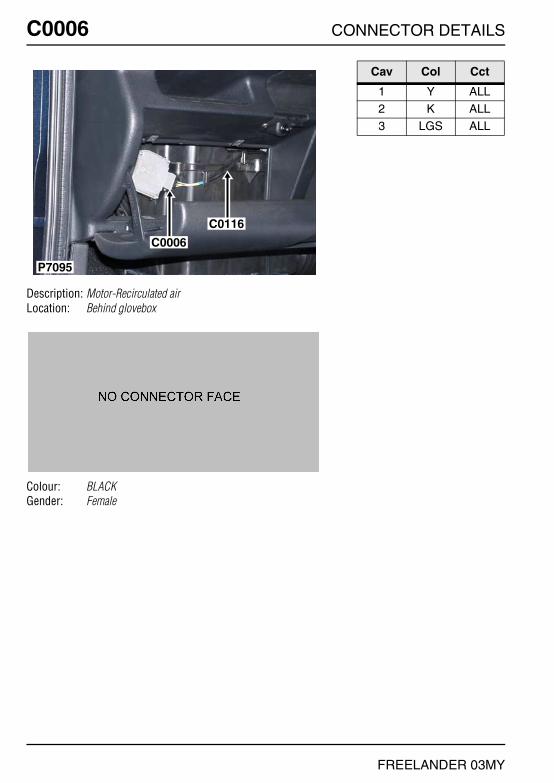
C0006 CONNECTOR DETAILS
FREELANDER 03MY
C0006
Description: Motor-Recirculated airLocation: Behind glovebox
Colour: BLACKGender: Female
P7095
C0006
C0116
Cav Col Cct
1 Y ALL2 K ALL3 LGS ALL

CONNECTOR DETAILS C0007
FREELANDER 03MY
C0007
Description: Switch-BonnetLocation: Rear of engine compartment
Colour: BLACKGender: Female
P6788
C0007C0018
Cav Col Cct
1 RP ALL2 B ALL

C0008 CONNECTOR DETAILS
FREELANDER 03MY
C0008
Description: Pump-Washer-WindscreenLocation: Behind RH side of front bumper
Colour: REDGender: Female
P6542
C0021C0008
Cav Col Cct
1 LGB ALL2 B ALL

CONNECTOR DETAILS C0009
FREELANDER 03MY
C0009
Description: Headlamp-LHLocation: Front LH side of engine compartment
Colour: BLACKGender: Female
P6560
C0071
C0009
C0017
Cav Col Cct
1 US ALL2 GR ALL3 B ALL
4 UK ALL5 RB ALL6 B ALL
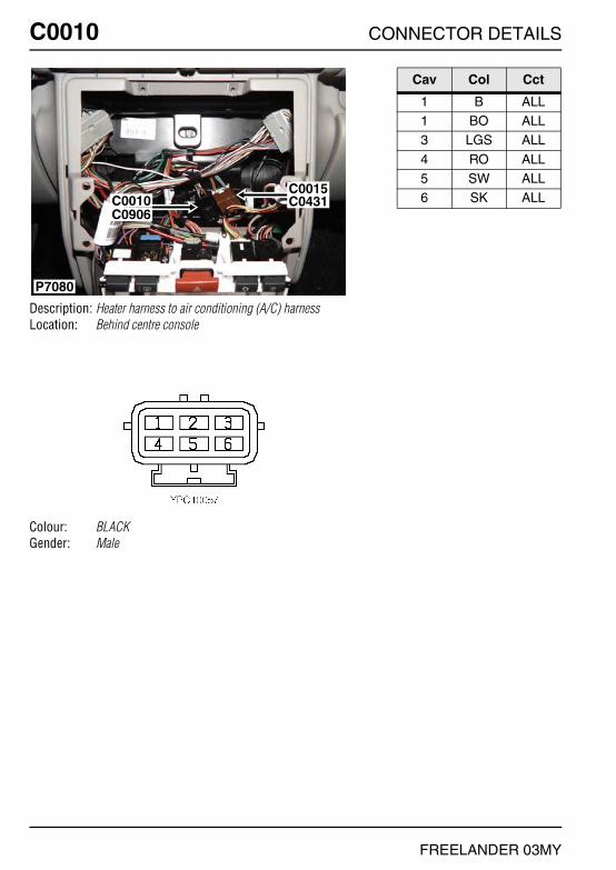
C0010 CONNECTOR DETAILS
FREELANDER 03MY
C0010
Description: Heater harness to air conditioning (A/C) harnessLocation: Behind centre console
Colour: BLACKGender: Male
P7080
C0015C0431C0010
C0906
Cav Col Cct
1 B ALL1 BO ALL3 LGS ALL
4 RO ALL5 SW ALL6 SK ALL
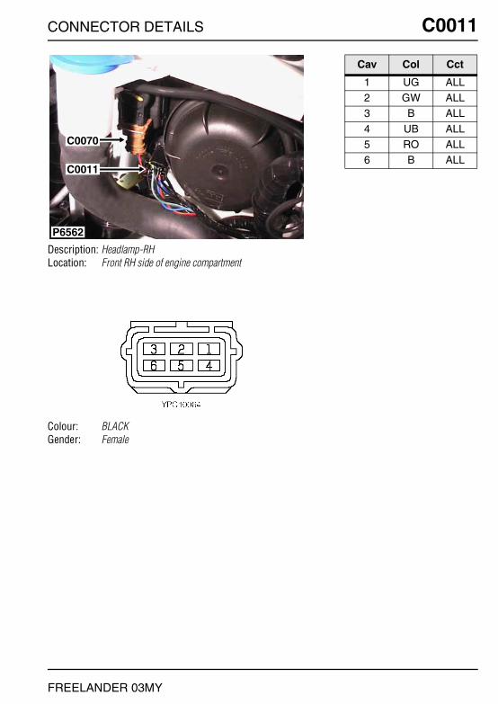
CONNECTOR DETAILS C0011
FREELANDER 03MY
C0011
Description: Headlamp-RHLocation: Front RH side of engine compartment
Colour: BLACKGender: Female
P6562
C0070
C0011
Cav Col Cct
1 UG ALL2 GW ALL3 B ALL
4 UB ALL5 RO ALL6 B ALL

C0012 CONNECTOR DETAILS
FREELANDER 03MY
C0012
Description: Lamp-Side repeater-Front-RHLocation: Behind RH side repeater lamp
Colour: BLACKGender: Female
P6558
C0012
Cav Col Cct
1 GW ALL2 B ALL

CONNECTOR DETAILS C0013
FREELANDER 03MY
C0013
Description: Lamp-Side repeater-Front-LHLocation: Behind LH side repeater lamp
Colour: BLACKGender: Female
P6557
C0013
Cav Col Cct
1 GR ALL2 B ALL

C0015 CONNECTOR DETAILS
FREELANDER 03MY
C0015
Description: Heater harness to main harnessLocation: Behind centre console
Colour: BROWNGender: Male
P7080
C0015C0431C0010
C0906
Cav Col Cct
1 GW ALL2 RO ALL3 SK ALL
4 B ALL5 LGS ALL

CONNECTOR DETAILS C0017
FREELANDER 03MY
C0017
Description: Header -EarthLocation: Lower LH front of engine compartment
Colour: NATURALGender: Female
P6560
C0071
C0009
C0017
Cav Col Cct
1 B ALL2 B ALL3 B ALL
4 B ALL5 B 176 B ALL

C0018 CONNECTOR DETAILS
FREELANDER 03MY
C0018
Description: Header -EarthLocation: Rear RH side of engine compartment
Colour: LIGHT GREYGender: Female
P6788
C0007C0018
Cav Col Cct
1 B 32 B 33 B 3
4 B 35 B 36 B 3
7 B 38 B 39 B 3
10 B 3

CONNECTOR DETAILS C0021
FREELANDER 03MY
C0021
Description: Pump-Washer-Rear screenLocation: Behind RH side of front bumper
Colour: BLACKGender: Female
P6542
C0021C0008
Cav Col Cct
1 GB ALL2 B ALL
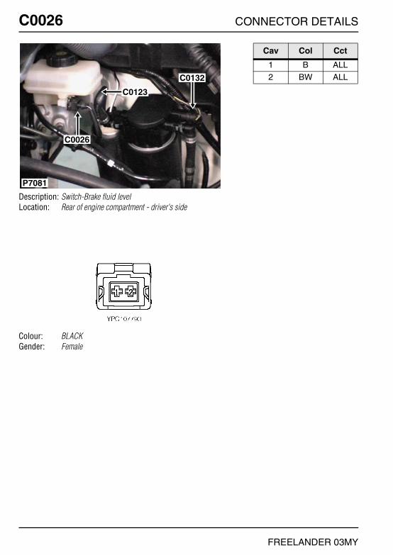
C0026 CONNECTOR DETAILS
FREELANDER 03MY
C0026
Description: Switch-Brake fluid levelLocation: Rear of engine compartment - driver's side
Colour: BLACKGender: Female
P7081
C0026
C0132
C0123
Cav Col Cct
1 B ALL2 BW ALL

CONNECTOR DETAILS C0028
FREELANDER 03MY
C0028
Description: Switch-IgnitionLocation: Underside of steering column
Colour: BROWNGender: Female
P6643
C0374
C0082
C0028
C0049
Cav Col Cct
1 N ALL2 NW ALL3 NR ALL
4 WR ALL5 G ALL6 SU ALL
7 PS ALL

C0030 CONNECTOR DETAILS
FREELANDER 03MY
C0030
Description: Motor-Wiper-WindscreenLocation: Beneath driver side of air intake plenum
Colour: BLACKGender: Female
P6632
C0030
Cav Col Cct
1 LG ALL2 B ALL3 RG ALL
4 NLG ALL5 ULG ALL

CONNECTOR DETAILS C0035
FREELANDER 03MY
C0035
Description: Switch-Wiper-FrontLocation: RH side of steering column
Colour: NATURALGender: Female
P6645
C0320
C0035
Cav Col Cct
1 LG ALL2 G ALL3 RG ALL
4 ULG ALL5 G ALL7 LGK ALL
8 LGB ALL
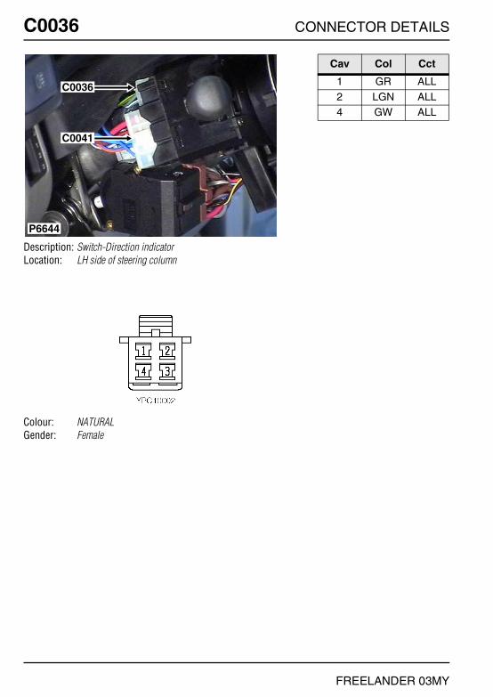
C0036 CONNECTOR DETAILS
FREELANDER 03MY
C0036
Description: Switch-Direction indicatorLocation: LH side of steering column
Colour: NATURALGender: Female
C0036
P6644
C0041
Cav Col Cct
1 GR ALL2 LGN ALL4 GW ALL

CONNECTOR DETAILS C0038
FREELANDER 03MY
C0038
Description: ResistorLocation: Top of engine
Colour:Gender:
P6800
C0038 C0276
C0556C0156
C1771
Cav Col Cct
1 B ALL2 B ALL

C0040 CONNECTOR DETAILS
FREELANDER 03MY
C0040
Description: Diagnostic socketLocation: Beneath centre console LH side
Colour: GREYGender: Female
P6789
C0040
Cav Col Cct
4 B ALL7 K ALL
13 K ALL
16 P ALL

CONNECTOR DETAILS C0041
FREELANDER 03MY
C0041
Description: Switch-LightingLocation: LH side of steering column
Colour: NATURALGender: Female
C0036
P6644
C0041
Cav Col Cct
1 U ALL2 UO ALL2 UG 25
3 RN ALL4 R ALL4 RW 25
5 UW ALL6 UN ALL

C0043 CONNECTOR DETAILS
FREELANDER 03MY
C0043
Description: Relay-Lift-Tail door windowLocation: Luggage compartment - RH side
Colour: BLACKGender: Female
C0043
C0124
P6805
Cav Col Cct
1 RU ALL2 PN ALL4 B ALL
6 UB ALL7 RG ALL9 UG ALL

CONNECTOR DETAILS C0046
FREELANDER 03MY
C0046
Description: Switch-Isolation-Window liftLocation: In rear of centre console
Colour: BLACKGender: Female
P6631
C0242
C0321
C0264
C0046
C0263
Cav Col Cct
1 SG 62 B 6
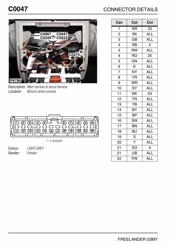
C0047 CONNECTOR DETAILS
FREELANDER 03MY
C0047
Description: Main harness to fascia harnessLocation: Behind centre console
Colour: LIGHT GREYGender: Female
P6786
C0047C0223
C0275
C0067C0229
Cav Col Cct
1 NR 232 SK ALL3 GB ALL
4 RB 44 RW ALL4 RO 25
5 GN ALL6 K ALL7 NY ALL
8 YR ALL9 WR ALL
10 SY ALL
11 NK 2312 YN ALL13 YB ALL
14 BY ALL15 BP ALL16 SW ALL
17 BN ALL18 BU ALL19 S ALL
20 Y ALL21 SO 421 UB ALL
22 PW ALL

CONNECTOR DETAILS C0049
FREELANDER 03MY
C0049
Description: Coil-TransponderLocation: RH side of steering column
Colour: BLACKGender: Female
P6643
C0374
C0082
C0028
C0049
Cav Col Cct
1 PW ALL3 P ALL5 KB ALL
6 B ALL7 KG ALL8 BR ALL
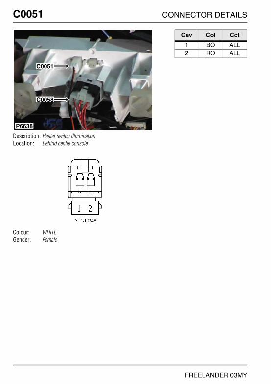
C0051 CONNECTOR DETAILS
FREELANDER 03MY
C0051
Description: Heater switch illuminationLocation: Behind centre console
Colour: WHITEGender: Female
P6638
C0051
C0058
Cav Col Cct
1 BO ALL2 RO ALL

CONNECTOR DETAILS C0052
FREELANDER 03MY
C0052
Description: Ignition coil-2 - KV6Location: Top of engine
Colour: BLACKGender: Female
P6574
C0052
C1770
C1772
Cav Col Cct
1 BG ALL2 B ALL3 NK ALL

C0052 CONNECTOR DETAILS
FREELANDER 03MY
C0052
Description: Ignition coil-2 - K1.8Location: Top of engine
Colour: BLACKGender: Female
P6615
C0052
C0156
Cav Col Cct
1 NK ALL2 WB ALL

CONNECTOR DETAILS C0052
FREELANDER 03MY
C0052
Description: Ignition coil-2 - NASLocation: Top of engine
Colour: BLACKGender: Female
P6574
C0052
C1770
C1772
Cav Col Cct
1 BG ALL2 B ALL3 NK ALL

C0053 CONNECTOR DETAILS
FREELANDER 03MY
C0053
Description: Control-Alternator - KV6Location: Top of engine
Colour: BLACKGender: Female
P6609
C0183C0053
Cav Col Cct
1 NY ALL2 W ALL3 GK ALL

CONNECTOR DETAILS C0053
FREELANDER 03MY
C0053
Description: Control-Alternator - NASLocation: Top of engine
Colour: BLACKGender: Female
P6609
C0183C0053
Cav Col Cct
1 NY ALL2 W ALL3 GK ALL

C0056 CONNECTOR DETAILS
FREELANDER 03MY
C0056
Description: Motor-BlowerLocation: Behind centre console
Colour:Gender:
P6567
C0211
C0056
Cav Col Cct
1 G ALL2 B ALL

CONNECTOR DETAILS C0058
FREELANDER 03MY
C0058
Description: Switch-Blower motorLocation: Behind centre console
Colour: NATURALGender: Female
P6638
C0051
C0058
Cav Col Cct
1 RY ALL2 RG ALL3 RS ALL
4 RK ALL5 LGS ALL6 SW ALL

C0059 CONNECTOR DETAILS
FREELANDER 03MY
C0059
Description: ECU-Engine ImmobilisationLocation: Behind centre of fascia
Colour: NATURALGender: Female
P6577
C0059
Cav Col Cct
1 B ALL2 PN ALL3 W ALL
4 K ALL5 WB ALL7 RW ALL
8 WR ALL9 G ALL
10 KB ALL
11 KG ALL13 KN ALL14 YR ALL
15 ON ALL

CONNECTOR DETAILS C0064
FREELANDER 03MY
C0064
Description: Switch-Fog guard lamp-RearLocation: Behind driver side of fascia
Colour: BLUEGender: Female
P6582
C0064
C0093
Cav Col Cct
1 RY ALL2 RO ALL4 B ALL

C0066 CONNECTOR DETAILS
FREELANDER 03MY
C0066
Description: Switch-MirrorLocation: Behind driver side of fascia
Colour: BLACKGender: Female
P6581
C0066
Cav Col Cct
1 BY ALL2 BP ALL3 SW ALL
4 B ALL5 BN ALL6 G ALL
7 BU ALL8 UB 7

CONNECTOR DETAILS C0067
FREELANDER 03MY
C0067
Description: Main harness to fascia harnessLocation: Behind centre console
Colour: LIGHT GREYGender: Female
P6786
C0047C0223
C0275
C0067C0229
Cav Col Cct
1 PB ALL2 UO ALL3 UG ALL
4 UB ALL4 RO 45 WU 16
5 GO ALL6 PN ALL7 W 23
8 GB ALL9 RW ALL
10 WR ALL
11 G ALL12 KN ALL13 YR ALL
14 ON ALL15 BR ALL16 B ALL
17 K ALL18 LGW ALL19 W 23
20 WY ALL

C0070 CONNECTOR DETAILS
FREELANDER 03MY
C0070
Description: Motor-Headlamp levelling-RHLocation: Front RH side of engine compartment
Colour: BROWNGender: Female
P6562
C0070
C0011
Cav Col Cct
1 RO ALL2 UB ALL3 B ALL

CONNECTOR DETAILS C0071
FREELANDER 03MY
C0071
Description: Motor-Headlamp levelling-LHLocation: Front LH side of engine compartment
Colour: BROWNGender: Female
P6560
C0071
C0009
C0017
Cav Col Cct
1 RB ALL2 UB ALL3 B ALL
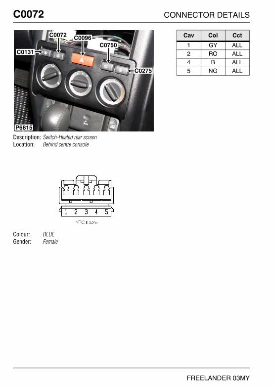
C0072 CONNECTOR DETAILS
FREELANDER 03MY
C0072
Description: Switch-Heated rear screenLocation: Behind centre console
Colour: BLUEGender: Female
C0131
C0275
C0750C0096C0072
P6815
Cav Col Cct
1 GY ALL2 RO ALL4 B ALL
5 NG ALL
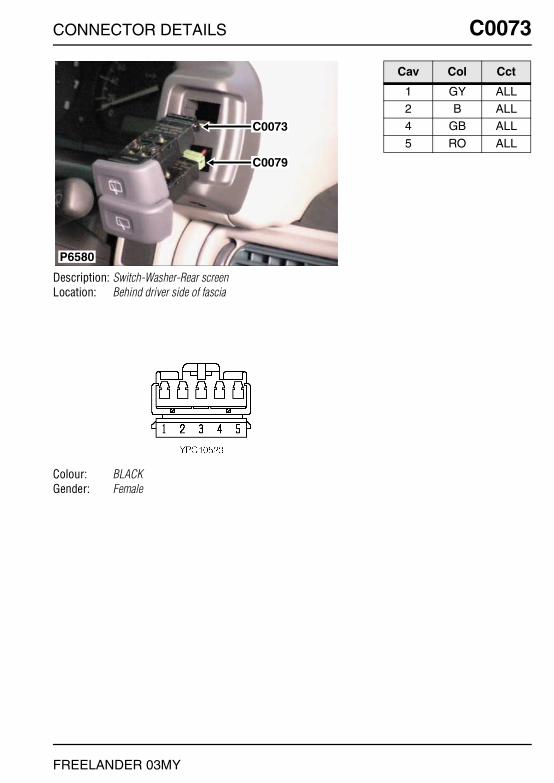
CONNECTOR DETAILS C0073
FREELANDER 03MY
C0073
Description: Switch-Washer-Rear screenLocation: Behind driver side of fascia
Colour: BLACKGender: Female
P6580
C0073
C0079
Cav Col Cct
1 GY ALL2 B ALL4 GB ALL
5 RO ALL

C0074 CONNECTOR DETAILS
FREELANDER 03MY
C0074
Description: Cigar lighter illuminationLocation: Behind centre console
Colour: WHITEGender: Female
P6584
C0328
C0074C0089
C0363
C0250
C0354
C0249
Cav Col Cct
1 RO ALL

CONNECTOR DETAILS C0075
FREELANDER 03MY
C0075
Description: Switch-Brake pedalLocation: Driver's footwell
Colour: WHITEGender: Female
P6830
C0292 C0286
C0075
C0787
C0652
Cav Col Cct
1 G ALL2 GR ALL3 GP ALL

C0079 CONNECTOR DETAILS
FREELANDER 03MY
C0079
Description: Switch-Wiper-RearLocation: Behind driver side of fascia
Colour: GREENGender: Female
P6580
C0073
C0079
Cav Col Cct
1 RG ALL2 RO ALL4 B ALL
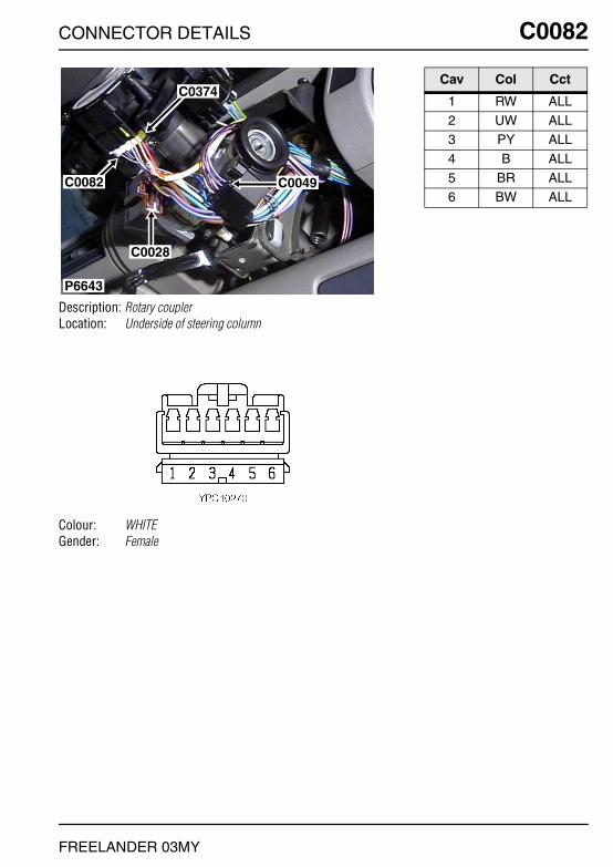
CONNECTOR DETAILS C0082
FREELANDER 03MY
C0082
Description: Rotary couplerLocation: Underside of steering column
Colour: WHITEGender: Female
P6643
C0374
C0082
C0028
C0049
Cav Col Cct
1 RW ALL2 UW ALL3 PY ALL
4 B ALL5 BR ALL6 BW ALL

C0084 CONNECTOR DETAILS
FREELANDER 03MY
C0084
Description: Main harness to roof harnessLocation: Behind driver side of fascia
Colour: LIGHT GREYGender: Female
P6554
C0084C0610
C0349C0421
C0341
Cav Col Cct
1 P ALL2 PW ALL3 B ALL
4 G ALL5 S ALL6 WB ALL
7 NB ALL8 SW ALL

CONNECTOR DETAILS C0089
FREELANDER 03MY
C0089
Description: Cigar lighterLocation: Behind centre console
Colour: BLACKGender: Female
P6584
C0328
C0074C0089
C0363
C0250
C0354
C0249
Cav Col Cct
1 B ALL2 PR ALL
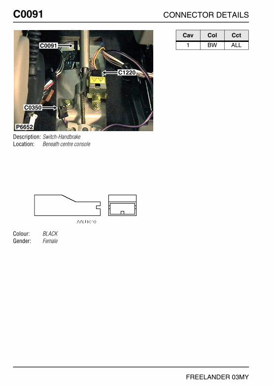
C0091 CONNECTOR DETAILS
FREELANDER 03MY
C0091
Description: Switch-HandbrakeLocation: Beneath centre console
Colour: BLACKGender: Female
P6652
C0091
C0350
C1220
Cav Col Cct
1 BW ALL

CONNECTOR DETAILS C0092
FREELANDER 03MY
C0092
Description: Head Unit-Audio SystemLocation: Behind centre console
Colour: BROWNGender: Female
C0092
C0921
P6816
Cav Col Cct
1 UK 91 BG ALL2 UB 9
2 BO ALL3 OK 93 BP ALL
4 OB 94 BU ALL5 YK 9
5 BW ALL6 YB 96 BS ALL
7 SK 97 BN ALL8 SB 9
8 BR ALL
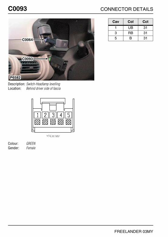
C0093 CONNECTOR DETAILS
FREELANDER 03MY
C0093
Description: Switch-Headlamp levellingLocation: Behind driver side of fascia
Colour: GREENGender: Female
P6582
C0064
C0093
Cav Col Cct
1 UB 313 RB 315 B 31
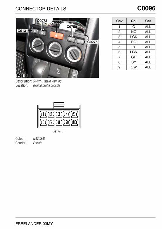
CONNECTOR DETAILS C0096
FREELANDER 03MY
C0096
Description: Switch-Hazard warningLocation: Behind centre console
Colour: NATURALGender: Female
C0131
C0275
C0750C0096C0072
P6815
Cav Col Cct
1 G ALL2 NO ALL3 LGK ALL
4 RO ALL5 B ALL6 LGN ALL
7 GR ALL8 SY ALL9 GW ALL

C0098 CONNECTOR DETAILS
FREELANDER 03MY
C0098
Description: Head Unit-Audio SystemLocation: Behind centre console
Colour: BLACKGender: Female
C0098C1354
P6814
Cav Col Cct
1 YK 82 OK 83 SK 8
5 LGW 86 UK 87 WRY 14
8 YB 89 P ALL
10 BW 8
11 OB 812 SB 813 RO 8
14 UB 815 B ALL17 BR 8

CONNECTOR DETAILS C0114
FREELANDER 03MY
C0114
Description: Unit-Fuel TankLocation: Beneath rear seat
Colour: BLACKGender: Female
P6833
C0114
Cav Col Cct
1 B ALL2 GB ALL3 B 30
4 WP 30

C0116 CONNECTOR DETAILS
FREELANDER 03MY
C0116
Description: DiodeLocation: Behind glovebox
Colour:Gender:
P7095
C0006
C0116
NO CONNECTOR FACE
Cav Col Cct
1 K ALL2 K ALL
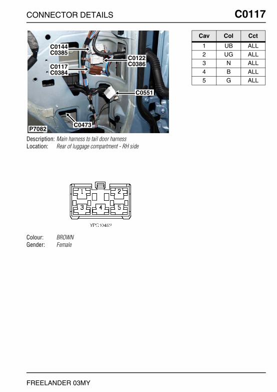
CONNECTOR DETAILS C0117
FREELANDER 03MY
C0117
Description: Main harness to tail door harnessLocation: Rear of luggage compartment - RH side
Colour: BROWNGender: Female
C0473
C0122C0386
C0144C0385
C0117C0384
C0551
P7082
Cav Col Cct
1 UB ALL2 UG ALL3 N ALL
4 B ALL5 G ALL

C0119 CONNECTOR DETAILS
FREELANDER 03MY
C0119
Description: Lamp-Load spaceLocation: Luggage compartment - RH side
Colour: BLACKGender: Female
P6535
C0119C0120
Cav Col Cct
1 P ALL
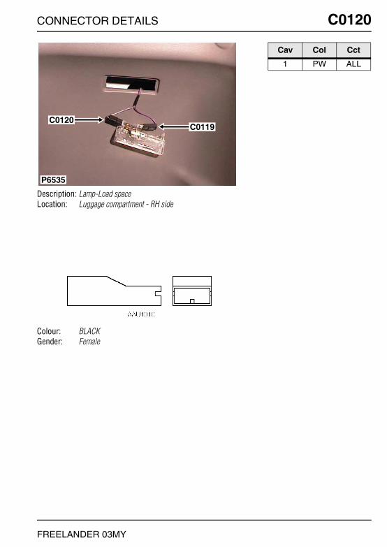
CONNECTOR DETAILS C0120
FREELANDER 03MY
C0120
Description: Lamp-Load spaceLocation: Luggage compartment - RH side
Colour: BLACKGender: Female
P6535
C0119C0120
Cav Col Cct
1 PW ALL

C0121 CONNECTOR DETAILS
FREELANDER 03MY
C0121
Description: Lamp-Tail-LHLocation: LH rear of vehicle
Colour: BLACKGender: Female
C0121
P6530
Cav Col Cct
1 B ALL2 GR ALL3 RB ALL
4 GP ALL

CONNECTOR DETAILS C0122
FREELANDER 03MY
C0122
Description: Main harness to tail door harnessLocation: Rear of luggage compartment - RH side
Colour: LIGHT GREYGender: Female
C0473
C0122C0386
C0144C0385
C0117C0384
C0551
P7082
Cav Col Cct
1 ON ALL2 BO ALL3 RO ALL
4 PU ALL5 GP ALL6 B ALL
7 GR ALL8 OB ALL

C0123 CONNECTOR DETAILS
FREELANDER 03MY
C0123
Description: Switch-InertiaLocation: Rear LH side of engine compartment
Colour: BLACKGender: Female
P7081
C0026
C0132
C0123
Cav Col Cct
1 G ALL3 GU ALL

CONNECTOR DETAILS C0124
FREELANDER 03MY
C0124
Description: Relay-Rear wiperLocation: Luggage compartment - RH side
Colour: BLACKGender: Female
C0043
C0124
P6805
Cav Col Cct
1 YW ALL2 PR ALL4 B ALL
6 G ALL7 YB ALL9 GR ALL

C0125 CONNECTOR DETAILS
FREELANDER 03MY
C0125
Description: Lamp-Tail-RHLocation: RH rear of vehicle
Colour: BLACKGender: Female
C0125
P6529
Cav Col Cct
1 B ALL2 GW ALL3 RO ALL
4 GP ALL
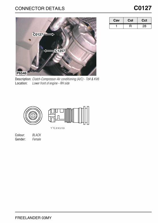
CONNECTOR DETAILS C0127
FREELANDER 03MY
C0127
Description: Clutch-Compressor-Air conditioning (A/C) - Td4 & KV6Location: Lower front of engine - RH side
Colour: BLACKGender: Female
P6546
C0127
C1257
Cav Col Cct
1 R 28

C0127 CONNECTOR DETAILS
FREELANDER 03MY
C0127
Description: Clutch-Compressor-Air conditioning (A/C) - K1.8Location: Lower front of engine - RH side
Colour: BLACKGender: Female
C0127
P6620
Cav Col Cct
1 R ALL

CONNECTOR DETAILS C0131
FREELANDER 03MY
C0131
Description: Switch-Heated front screenLocation: Behind centre console
Colour: BLACKGender: Female
C0131
C0275
C0750C0096C0072
P6815
Cav Col Cct
1 KO 282 RO 284 B 28
5 PK 28

C0132 CONNECTOR DETAILS
FREELANDER 03MY
C0132
Description: Sensor-Low fuel pressureLocation: Rear LH side of engine compartment
Colour: BLACKGender: Female
P7081
C0026
C0132
C0123
Cav Col Cct
1 PG 172 BG 173 GS 17
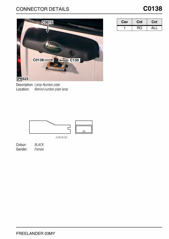
CONNECTOR DETAILS C0138
FREELANDER 03MY
C0138
Description: Lamp-Number plateLocation: Behind number plate lamp
Colour: BLACKGender: Female
P6523
C0138 C139
C0615 Cav Col Cct
1 RO ALL

C0139 CONNECTOR DETAILS
FREELANDER 03MY
C0139
Description: Lamp-Number plateLocation: Behind number plate lamp
Colour: BLACKGender: Female
P6523
C0138 C139
C0615 Cav Col Cct
1 B 382 B 37

CONNECTOR DETAILS C0144
FREELANDER 03MY
C0144
Description: Main harness to tail door harnessLocation: Rear of luggage compartment - RH side
Colour: LIGHT GREYGender: Female
C0473
C0122C0386
C0144C0385
C0117C0384
C0551
P7082
Cav Col Cct
1 KB ALL3 SR ALL4 SP ALL
5 US ALL6 NG ALL
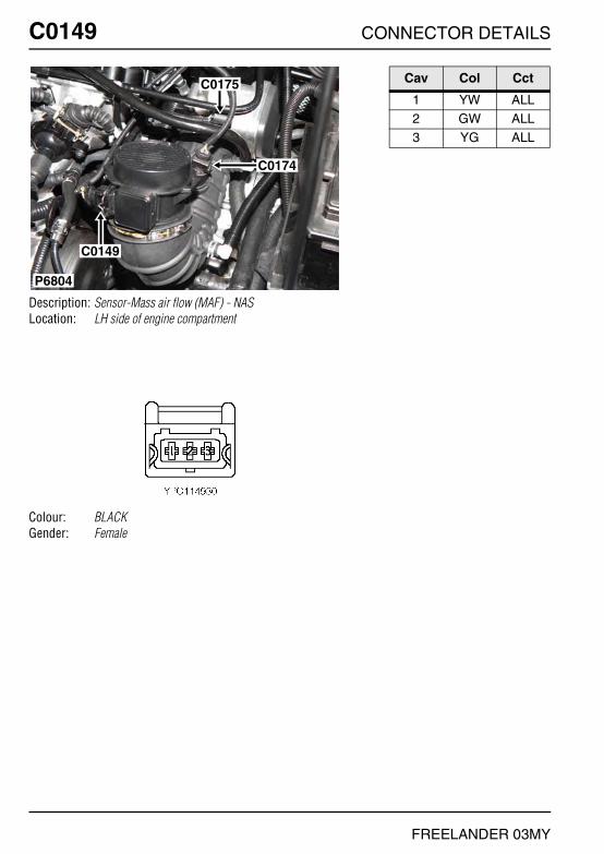
C0149 CONNECTOR DETAILS
FREELANDER 03MY
C0149
Description: Sensor-Mass air flow (MAF) - NASLocation: LH side of engine compartment
Colour: BLACKGender: Female
C0175
C0174
C0149
P6804
Cav Col Cct
1 YW ALL2 GW ALL3 YG ALL

CONNECTOR DETAILS C0149
FREELANDER 03MY
C0149
Description: Sensor-Mass air flow (MAF) - Td4Location: Top of engine
Colour: BLACKGender: Female
P6597
C0149
Cav Col Cct
1 UW ALL2 RW ALL3 B ALL
4 RY ALL5 Y ALL

C0150 CONNECTOR DETAILS
FREELANDER 03MY
C0150
Description: Sensor-Knock (KS) - KV6Location: Rear LH side of engine
Colour: BLACKGender: Female
C0150
P6623
Cav Col Cct
1 LGS ALL2 BK ALL3 BO ALL
4 BK ALL

CONNECTOR DETAILS C0150
FREELANDER 03MY
C0150
Description: Sensor-Knock (KS) - NASLocation: Rear LH side of engine
Colour: BLACKGender: Female
C0150
P6623
Cav Col Cct
1 LGS ALL2 BK ALL3 BO ALL
4 BK ALL
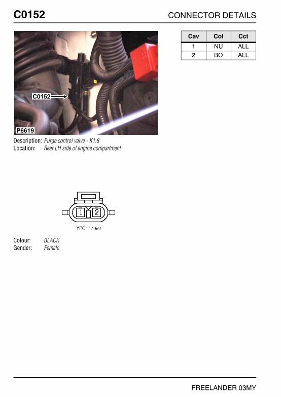
C0152 CONNECTOR DETAILS
FREELANDER 03MY
C0152
Description: Purge control valve - K1.8Location: Rear LH side of engine compartment
Colour: BLACKGender: Female
P6619
C0152
Cav Col Cct
1 NU ALL2 BO ALL

CONNECTOR DETAILS C0152
FREELANDER 03MY
C0152
Description: Purge control valve - KV6Location: Top of engine
Colour: BLACKGender: Female
P6607
C0567
C0177
C0175
C0152 Cav Col Cct
1 YU ALL2 BO ALL

C0152 CONNECTOR DETAILS
FREELANDER 03MY
C0152
Description: Purge control valve - NASLocation: Rear of engine compartment
Colour: BLACKGender: Female
P6803
C1977
C0152
Cav Col Cct
1 YU ALL2 BO ALL

CONNECTOR DETAILS C0153
FREELANDER 03MY
C0153
Description: Relay-BlowerLocation: Behind centre console
Colour:Gender:
P6826
C0550
C0420C1023
C0417
C0294
C0290
C0153
Cav Col Cct
30 GW ALL85 BS ALL86 RS ALL
87 GR ALL
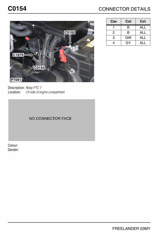
C0154 CONNECTOR DETAILS
FREELANDER 03MY
C0154
Description: Relay-PTC 1Location: LH side of engine compartment
Colour:Gender:
C0192
C1876
C0154
P7091
Cav Col Cct
1 B ALL2 B ALL3 GW ALL
4 GY ALL
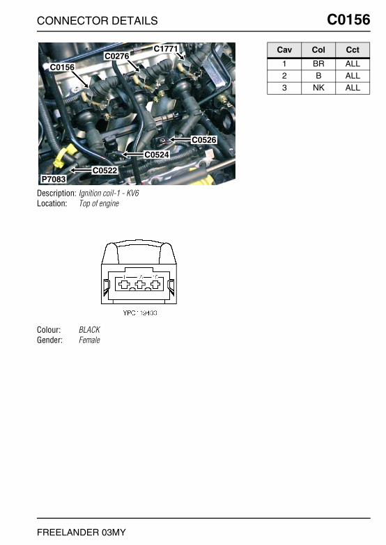
CONNECTOR DETAILS C0156
FREELANDER 03MY
C0156
Description: Ignition coil-1 - KV6Location: Top of engine
Colour: BLACKGender: Female
P7083
C1771C0276
C0526
C0524
C0522
C0156
Cav Col Cct
1 BR ALL2 B ALL3 NK ALL

C0156 CONNECTOR DETAILS
FREELANDER 03MY
C0156
Description: Ignition coil-1 - K1.8Location: Top of engine
Colour: BLACKGender: Female
P6615
C0052
C0156
Cav Col Cct
1 NK ALL2 WO ALL

CONNECTOR DETAILS C0156
FREELANDER 03MY
C0156
Description: Ignition coil-1 - NASLocation: Top of engine
Colour: BLACKGender: Female
P6800
C0038 C0276
C0556C0156
C1771
Cav Col Cct
1 BR ALL2 B ALL3 NK ALL

C0157 CONNECTOR DETAILS
FREELANDER 03MY
C0157
Description: Relay-PTC 2Location: Rear LH side of engine compartment
Colour: BLACKGender: Female
P7093
C0420C0483
C0157
C1875
Cav Col Cct
1 N ALL2 G ALL3 B ALL
4 GR ALL

CONNECTOR DETAILS C0162
FREELANDER 03MY
C0162
Description: Engine harness to main harness - K1.8Location: Inside E-box
Colour: LIGHT GREYGender: Male
P6618
C0914
C0162C0448
C0913
Cav Col Cct
1 G ALL2 GN ALL3 GB ALL
4 B ALL5 KB ALL6 LGS ALL
7 GU ALL8 GO ALL9 BO ALL
12 NR ALL

C0163 CONNECTOR DETAILS
FREELANDER 03MY
C0163
Description: Switch-Reverse - Td4Location: Gearbox - Rear
Colour: BLACKGender: Female
C0163
P7101
Cav Col Cct
1 GN ALL2 G ALL

CONNECTOR DETAILS C0163
FREELANDER 03MY
C0163
Description: Switch-Reverse - K1.8Location: Above gearbox
Colour: BLACKGender: Female
C0163 C0166
C0618C0169
P6617
Cav Col Cct
1 G ALL

C0164 CONNECTOR DETAILS
FREELANDER 03MY
C0164
Description: Sensor-Heated oxygen (HO2S)-Front - K1.8Location: RH side of engine compartment
Colour: BLACKGender: Female
P6838
C0175
C0171C0521
C0176
C0164
C0567 Cav Col Cct
1 KB ALL2 LGS ALL3 BU ALL
4 NU ALL

CONNECTOR DETAILS C0164
FREELANDER 03MY
C0164
Description: Sensor-Heated oxygen (HO2S)-Front - KV6Location: Front of engine - centre
Colour: BLACKGender: Female
C0164
P6547
Cav Col Cct
1 UY ALL2 BG ALL3 UN ALL
4 YG ALL

C0166 CONNECTOR DETAILS
FREELANDER 03MY
C0166
Description: Switch-Reverse - K1.8Location: Above gearbox
Colour: BLACKGender: Male
C0163 C0166
C0618C0169
P6617
Cav Col Cct
1 GN ALL

CONNECTOR DETAILS C0167
FREELANDER 03MY
C0167
Description: Link harness to main harnessLocation: Beneath engine compartment fusebox
Colour: GREYGender: Female
P7102
C0420C0167
Cav Col Cct
1 GN 172 G 17

C0168 CONNECTOR DETAILS
FREELANDER 03MY
C0168
Description: Sensor-Crankshaft position (CKP) - K1.8Location: Centre rear of engine
Colour: WHITEGender: Female
P6662
C0168
Cav Col Cct
1 B ALL2 NB ALL

CONNECTOR DETAILS C0169
FREELANDER 03MY
C0169
Description: Sensor-Engine coolant temperature (ECT)Location: Above gearbox
Colour: BLACKGender: Female
P6624
C0169
Cav Col Cct
1 GU 42 UG 4
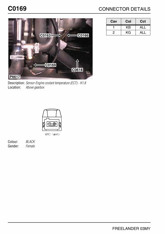
C0169 CONNECTOR DETAILS
FREELANDER 03MY
C0169
Description: Sensor-Engine coolant temperature (ECT) - K1.8Location: Above gearbox
Colour: BLACKGender: Female
C0163 C0166
C0618C0169
P6617
Cav Col Cct
1 KB ALL2 KG ALL
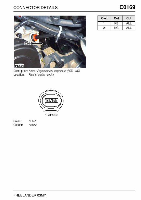
CONNECTOR DETAILS C0169
FREELANDER 03MY
C0169
Description: Sensor-Engine coolant temperature (ECT) - KV6Location: Front of engine - centre
Colour: BLACKGender: Female
P6624
C0169
Cav Col Cct
1 KB ALL2 KG ALL

C0169 CONNECTOR DETAILS
FREELANDER 03MY
C0169
Description: Sensor-Engine coolant temperature (ECT) - NASLocation: Front of engine - centre
Colour: BLACKGender: Female
P6624
C0169
Cav Col Cct
1 KB ALL2 KG ALL

CONNECTOR DETAILS C0170
FREELANDER 03MY
C0170
Description: Sensor-Crankshaft position (CKP) - KV6Location: Rear LH side of engine
Colour: BLACKGender: Female
C0170
C0643
P6790
Cav Col Cct
1 BS ALL2 WU ALL3 YU ALL

C0170 CONNECTOR DETAILS
FREELANDER 03MY
C0170
Description: Sensor-Crankshaft position (CKP) - NASLocation: Rear LH side of engine
Colour: BLACKGender: Female
C0170
C0643
P6790
Cav Col Cct
1 BS ALL2 WU ALL3 YU ALL
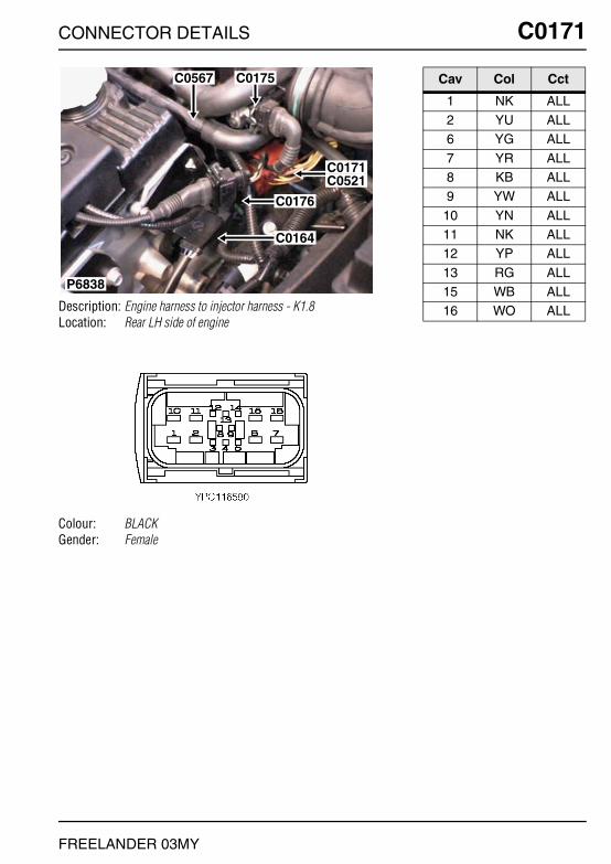
CONNECTOR DETAILS C0171
FREELANDER 03MY
C0171
Description: Engine harness to injector harness - K1.8Location: Rear LH side of engine
Colour: BLACKGender: Female
P6838
C0175
C0171C0521
C0176
C0164
C0567 Cav Col Cct
1 NK ALL2 YU ALL6 YG ALL
7 YR ALL8 KB ALL9 YW ALL
10 YN ALL11 NK ALL12 YP ALL
13 RG ALL15 WB ALL16 WO ALL
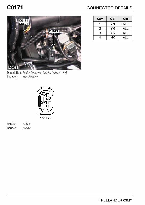
C0171 CONNECTOR DETAILS
FREELANDER 03MY
C0171
Description: Engine harness to injector harness - KV6Location: Top of engine
Colour: BLACKGender: Female
P6573
C1972
C0521C0171
Cav Col Cct
1 YN ALL2 YR ALL3 YG ALL
4 NK ALL

CONNECTOR DETAILS C0171
FREELANDER 03MY
C0171
Description: Engine harness to injector harness - NASLocation: Top of engine
Colour: BLACKGender: Female
P6842
C0521C0171
Cav Col Cct
1 YN ALL2 YR ALL3 YG ALL
4 NK ALL

C0174 CONNECTOR DETAILS
FREELANDER 03MY
C0174
Description: Sensor-Inlet air temperature (IAT) - NASLocation: LH side of engine compartment
Colour: BLACKGender: Female
C0175
C0174
C0149
P6804
Cav Col Cct
1 OG ALL2 OS ALL

CONNECTOR DETAILS C0175
FREELANDER 03MY
C0175
Description: Sensor-Throttle position (TP) - Td4Location: Behind driver side of fascia
Colour: NATURALGender: Male
C0175
P7099
Cav Col Cct
1 RY ALL2 RN ALL4 RU ALL
5 YRB ALL6 NRB ALL8 URB ALL

C0175 CONNECTOR DETAILS
FREELANDER 03MY
C0175
Description: Sensor-Throttle position (TP) - K1.8Location: Top of engine
Colour: BLACKGender: Female
P6838
C0175
C0171C0521
C0176
C0164
C0567 Cav Col Cct
1 KP ALL2 GY ALL3 KB ALL

CONNECTOR DETAILS C0175
FREELANDER 03MY
C0175
Description: Sensor-Throttle position (TP) - KV6Location: Top of engine
Colour: BLACKGender: Female
P6607
C0567
C0177
C0175
C0152 Cav Col Cct
1 GU ALL2 BLG ALL3 KB ALL

C0175 CONNECTOR DETAILS
FREELANDER 03MY
C0175
Description: Sensor-Throttle position (TP) - NASLocation: LH side of engine compartment
Colour:Gender:
C0175
C0174
C0149
P6804
Cav Col Cct
1 NP ALL2 NW ALL3 NB ALL
4 NU ALL5 GW ALL6 NG ALL

CONNECTOR DETAILS C0176
FREELANDER 03MY
C0176
Description: Sensor-Camshaft position (CMP) - K1.8Location: Top of engine
Colour: BLACKGender: Female
P6838
C0175
C0171C0521
C0176
C0164
C0567 Cav Col Cct
1 NU ALL2 YP ALL3 BS ALL

C0176 CONNECTOR DETAILS
FREELANDER 03MY
C0176
Description: Sensor-Camshaft position (CMP) - KV6Location: Top of engine
Colour: BLACKGender: Female
P6611
C0176
C0164
Cav Col Cct
1 YG ALL2 UG ALL3 BS ALL

CONNECTOR DETAILS C0176
FREELANDER 03MY
C0176
Description: Sensor-Camshaft position (CMP) - NASLocation: Top of engine
Colour: BLACKGender: Female
P6611
C0176
C0164
Cav Col Cct
1 YG ALL2 UG ALL3 BS ALL

C0176 CONNECTOR DETAILS
FREELANDER 03MY
C0176
Description: Sensor-Camshaft position (CMP) - Td4Location: Top of engine
Colour: BLACKGender: Female
P6596
C0176
C0523
C0522
C0524
C0525
Cav Col Cct
1 RW ALL2 Y ALL3 N ALL

CONNECTOR DETAILS C0177
FREELANDER 03MY
C0177
Description: Idle air control valve (IACV) - K1.8Location: Top of engine
Colour: BLACKGender: Female
P6614
C0522 C0523 C0524 C0525
C0567 C0177
Cav Col Cct
A KU ALLB OG ALLC OS ALL
D OU ALL

C0177 CONNECTOR DETAILS
FREELANDER 03MY
C0177
Description: Idle air control valve (IACV) - KV6Location: Top of engine
Colour: BLACKGender: Female
P6607
C0567
C0177
C0175
C0152 Cav Col Cct
A OG ALLB OS ALLC KU ALL
D OU ALL

CONNECTOR DETAILS C0178
FREELANDER 03MY
C0178
Description: Starter motor - Td4Location: Front of engine - centre
Colour:Gender:
P6625
C0178
Cav Col Cct
1 B ALL
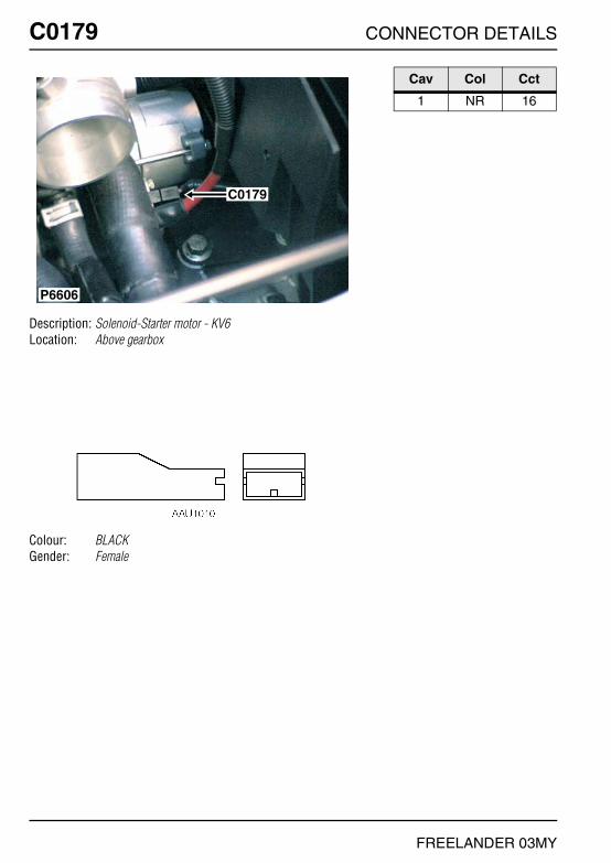
C0179 CONNECTOR DETAILS
FREELANDER 03MY
C0179
Description: Solenoid-Starter motor - KV6Location: Above gearbox
Colour: BLACKGender: Female
C0179
P6606
Cav Col Cct
1 NR 16

CONNECTOR DETAILS C0179
FREELANDER 03MY
C0179
Description: Solenoid-Starter motor - K1.8Location: Above gearbox
Colour: BLACKGender: Female
P6622
C0179
Cav Col Cct
1 NR ALL

C0183 CONNECTOR DETAILS
FREELANDER 03MY
C0183
Description: Power-Alternator - K1.8Location: Front of engine - centre
Colour:Gender:
P6621
C0183
C0185
Cav Col Cct
1 R ALL

CONNECTOR DETAILS C0183
FREELANDER 03MY
C0183
Description: Power-Alternator - KV6Location: Top of engine
Colour:Gender:
P6609
C0183C0053
Cav Col Cct
1 R ALL
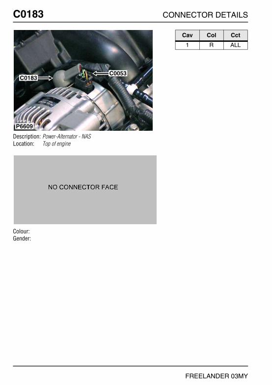
C0183 CONNECTOR DETAILS
FREELANDER 03MY
C0183
Description: Power-Alternator - NASLocation: Top of engine
Colour:Gender:
P6609
C0183C0053
Cav Col Cct
1 R ALL

CONNECTOR DETAILS C0185
FREELANDER 03MY
C0185
Description: Warning lamp-Ignition/no charge - K1.8Location: Front of engine - centre
Colour: BLACKGender: Female
P6621
C0183
C0185
Cav Col Cct
1 NY ALL2 W ALL3 WR ALL

C0187 CONNECTOR DETAILS
FREELANDER 03MY
C0187
Description: Switch-Oil pressure - K1.8Location: Lower front of engine - RH side
Colour: BLACKGender: Female
P6626
C0187
Cav Col Cct
1 WN ALL
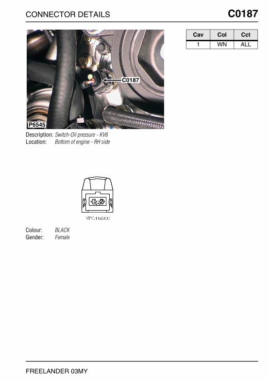
CONNECTOR DETAILS C0187
FREELANDER 03MY
C0187
Description: Switch-Oil pressure - KV6Location: Bottom of engine - RH side
Colour: BLACKGender: Female
P6545
C0187
Cav Col Cct
1 WN ALL

C0187 CONNECTOR DETAILS
FREELANDER 03MY
C0187
Description: Switch-Oil pressure - NASLocation: Bottom of engine - RH side
Colour: BLACKGender: Female
P6545
C0187
Cav Col Cct
1 WN ALL
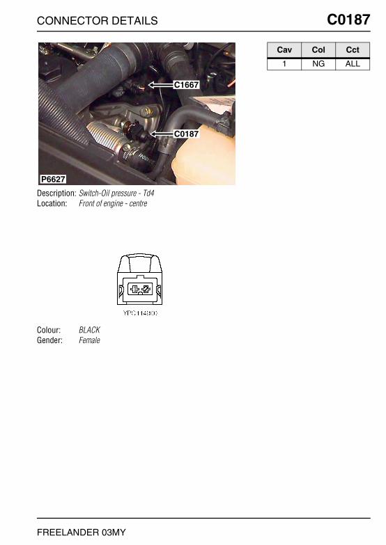
CONNECTOR DETAILS C0187
FREELANDER 03MY
C0187
Description: Switch-Oil pressure - Td4Location: Front of engine - centre
Colour: BLACKGender: Female
P6627
C1667
C0187
Cav Col Cct
1 NG ALL
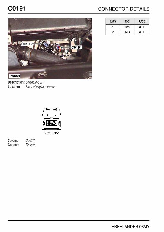
C0191 CONNECTOR DETAILS
FREELANDER 03MY
C0191
Description: Solenoid-EGRLocation: Front of engine - centre
Colour: BLACKGender: Female
P6663
C0196C0191
Cav Col Cct
1 RW ALL2 NS ALL

CONNECTOR DETAILS C0192
FREELANDER 03MY
C0192
Description: BatteryLocation: Front LH side of engine compartment
Colour: TIN-PLATEGender: Eyelet
P6811
C0192
C0994
C1860
Cav Col Cct
1 N ALL

C0192 CONNECTOR DETAILS
FREELANDER 03MY
C0192
Description: BatteryLocation: Front LH side of engine compartment
Colour: TIN-PLATEGender: Eyelet
C0192
C1876
C0154
P7091
Cav Col Cct
1 R ALL

CONNECTOR DETAILS C0195
FREELANDER 03MY
C0195
Description: Speed transducerLocation: Front of engine - centre
Colour: BLACKGender: Female
P6628
C0195
Cav Col Cct
1 B ALL2 Y ALL

C0196 CONNECTOR DETAILS
FREELANDER 03MY
C0196
Description: Sensor-Engine coolant temperature (ECT) - Td4Location: Front of engine - centre
Colour: BLACKGender: Female
P6663
C0196C0191
Cav Col Cct
1 SU ALL2 NG ALL

CONNECTOR DETAILS C0200
FREELANDER 03MY
C0200
Description: Engine harness to main harness - NASLocation: Inside E-box
Colour: LIGHT GREYGender: Male
P6809
C0646C0200C0451
C0932
C1258
Cav Col Cct
1 NK ALL2 BG ALL3 OU ALL
4 GK ALL5 UK ALL

C0201 CONNECTOR DETAILS
FREELANDER 03MY
C0201
Description: Dimmer-Instrument illuminationLocation: Behind driver side of fascia
Colour: NATURALGender: Female
P6819
C0201
Cav Col Cct
1 B 192 RB ALL3 RO ALL
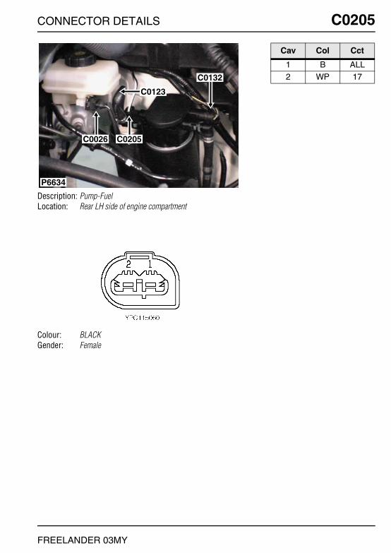
CONNECTOR DETAILS C0205
FREELANDER 03MY
C0205
Description: Pump-FuelLocation: Rear LH side of engine compartment
Colour: BLACKGender: Female
P6634
C0205C0026
C0132
C0123
Cav Col Cct
1 B ALL2 WP 17

C0208 CONNECTOR DETAILS
FREELANDER 03MY
C0208
Description: Control Unit-Cooling FanLocation: Front of engine compartment - centre
Colour:Gender:
P6824
C0208
C1680
Cav Col Cct
1 NG 342 B 34

CONNECTOR DETAILS C0211
FREELANDER 03MY
C0211
Description: Switch-Throttle pedalLocation: Driver's footwell
Colour: NATURALGender: Female
P6567
C0211
C0056
Cav Col Cct
1 W 302 B 304 UY ALL
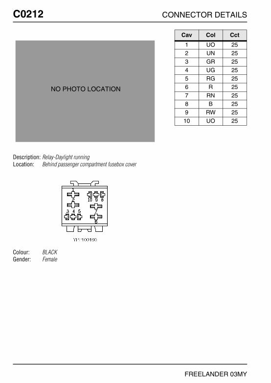
C0212 CONNECTOR DETAILS
FREELANDER 03MY
C0212
Description: Relay-Daylight runningLocation: Behind passenger compartment fusebox cover
Colour: BLACKGender: Female
NO PHOTO LOCATION
Cav Col Cct
1 UO 252 UN 253 GR 25
4 UG 255 RG 256 R 25
7 RN 258 B 259 RW 25
10 UO 25

CONNECTOR DETAILS C0215
FREELANDER 03MY
C0215
Description: Relay-Glow plugLocation: Inside E-box
Colour: BLACKGender: Female
P7100
C0215
Cav Col Cct
1 BR 172 RW 173 N 17
5 NW 17

C0216 CONNECTOR DETAILS
FREELANDER 03MY
C0216
Description: Sensor-Boost pressureLocation: Top of engine
Colour: BLACKGender: Female
P6598
C0216
Cav Col Cct
1 UY ALL2 NG ALL3 W ALL

CONNECTOR DETAILS C0222
FREELANDER 03MY
C0222
Description: Switch-Glove boxLocation: Behind passenger side of fascia
Colour: BLACKGender: Female
P6648
C0238 C0222
Cav Col Cct
1 B ALL

C0223 CONNECTOR DETAILS
FREELANDER 03MY
C0223
Description: Fascia harness to main harnessLocation: Behind centre console
Colour: LIGHT GREYGender: Male
P6786
C0047C0223
C0275
C0067C0229
Cav Col Cct
1 NK 201 NR 232 SK ALL
3 GB ALL4 RB 44 RW 29
5 GN ALL6 K ALL7 NY ALL
8 YR ALL9 WR ALL
10 SY ALL
11 NK ALL12 YN ALL13 YB ALL
14 BY ALL15 BP ALL16 SW ALL
17 BN ALL18 BU ALL19 S ALL
20 Y ALL21 SO 421 UB 7
22 PW ALL

CONNECTOR DETAILS C0226
FREELANDER 03MY
C0226
Description: Alternator/generatorLocation: Front RH side of engine
Colour: BLACKGender: Female
P6599
C0226
Cav Col Cct
1 GN ALL2 U ALL

C0227 CONNECTOR DETAILS
FREELANDER 03MY
C0227
Description: Lamp-Glove boxLocation: Glovebox - inside
Colour: BLACKGender: Female
P6588
C0235C0227
Cav Col Cct
1 RO ALL

CONNECTOR DETAILS C0229
FREELANDER 03MY
C0229
Description: Fascia harness to main harnessLocation: Behind centre console
Colour: LIGHT GREYGender: Male
P6786
C0047C0223
C0275
C0067C0229
Cav Col Cct
1 PB 262 UO 263 UG 26
4 RO 44 UB 315 GO 26
5 WU 276 PN ALL7 W ALL
8 GB ALL9 RW ALL
10 WR ALL
11 G ALL12 KN ALL13 YR ALL
14 ON ALL15 BR ALL16 B ALL
17 K ALL18 LGW ALL19 WK ALL
20 WY ALL

C0230 CONNECTOR DETAILS
FREELANDER 03MY
C0230
Description: Instrument PackLocation: Behind instrument pack
Colour: GREYGender: Female
P6839
C0359
C1000
C0230
C0719
C0233
Cav Col Cct
1 RP ALL4 WB ALL5 WU 27
7 RW 298 UO 269 UG 26
10 PB 2611 K ALL12 YB ALL
14 UY ALL15 GP ALL18 SO 4
20 GO 2621 GB ALL23 P ALL
24 B ALL25 YN ALL
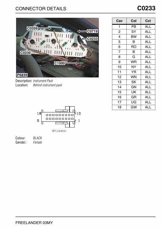
CONNECTOR DETAILS C0233
FREELANDER 03MY
C0233
Description: Instrument PackLocation: Behind instrument pack
Colour: BLACKGender: Female
P6839
C0359
C1000
C0230
C0719
C0233
Cav Col Cct
1 PB ALL2 SY ALL4 BW ALL
5 B ALL6 RO ALL7 B ALL
8 G ALL9 WR ALL
10 NY ALL
11 YR ALL12 WN ALL13 SK ALL
14 GN ALL15 UK ALL16 GR ALL
17 UG ALL18 GW ALL

C0235 CONNECTOR DETAILS
FREELANDER 03MY
C0235
Description: Lamp-Glove boxLocation: Glovebox - inside
Colour: BLACKGender: Female
P6588
C0235C0227
Cav Col Cct
1 BR ALL
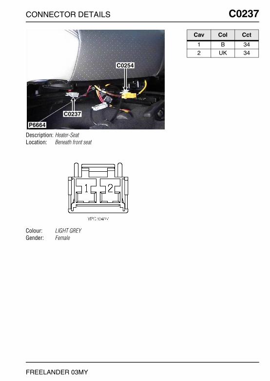
CONNECTOR DETAILS C0237
FREELANDER 03MY
C0237
Description: Heater-SeatLocation: Beneath front seat
Colour: LIGHT GREYGender: Female
P6664
C0237
C0254
Cav Col Cct
1 B 342 UK 34
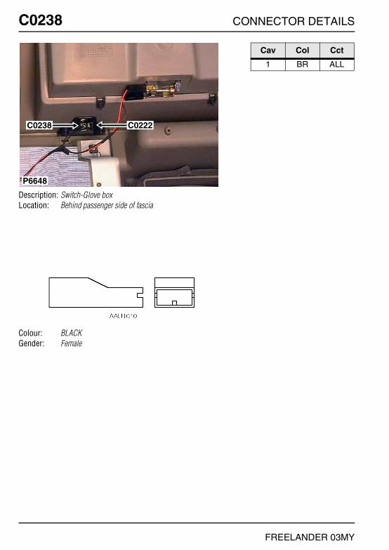
C0238 CONNECTOR DETAILS
FREELANDER 03MY
C0238
Description: Switch-Glove boxLocation: Behind passenger side of fascia
Colour: BLACKGender: Female
P6648
C0238 C0222
Cav Col Cct
1 BR ALL

CONNECTOR DETAILS C0239
FREELANDER 03MY
C0239
Description: ECU-Cruise controlLocation: Beneath RH seat
Colour: BLACKGender: Female
P6651
C0239
C1959
Cav Col Cct
1 PG 162 UW 164 RW 16
5 GP 167 BR 168 WY 16
11 WU 1615 WO 1616 K 16
17 PY 1618 B 16

C0241 CONNECTOR DETAILS
FREELANDER 03MY
C0241
Description: Clock-DigitalLocation: Fascia - top centre
Colour: WHITEGender: Female
C0241
P6575
Cav Col Cct
1 P 292 B ALL3 LGW ALL
4 RO ALL4 RB 158 P 4

CONNECTOR DETAILS C0242
FREELANDER 03MY
C0242
Description: Switch-Window-Front-RHLocation: In rear of centre console
Colour: WHITEGender: Female
P6631
C0242
C0321
C0264
C0046
C0263
Cav Col Cct
1 B ALL2 SO ALL3 OU 2
3 OY 34 OR 24 OG 3
6 RO ALL

C0243 CONNECTOR DETAILS
FREELANDER 03MY
C0243
Description: Solenoid-GearboxLocation: Front LH side of engine compartment
Colour: BLACKGender: Female
P6605
C0244
C0243
Cav Col Cct
SCR SCR ALL1 U 232 R 23
3 B 234 R 235 W 23
6 U 237 WK 238 KB 23
9 R 2310 O 2311 OU 23
12 K 2313 GR 2314 OG 23
15 Y 2316 GP 2317 U 23
18 SB 23

CONNECTOR DETAILS C0244
FREELANDER 03MY
C0244
Description: Selector-Automatic transmissionLocation: Front LH side of engine compartment
Colour: BLACKGender: Female
P6605
C0244
C0243
Cav Col Cct
1 WB 232 WU 233 OB 23
4 RG 235 GY 236 W 23
7 NG 238 NR 239 KO ALL
10 W 23

C0246 CONNECTOR DETAILS
FREELANDER 03MY
C0246
Description: Heated screen-FrontLocation: Behind RH side of fascia
Colour: NATURALGender: Male
P6834
C0246
Cav Col Cct
1 PW ALL

CONNECTOR DETAILS C0247
FREELANDER 03MY
C0247
Description: Heated screen-FrontLocation: Behind LH side of fascia
Colour: NATURALGender: Male
C0247
P6836
Cav Col Cct
1 PS ALL

C0248 CONNECTOR DETAILS
FREELANDER 03MY
C0248
Description: Heated seat-LHLocation: Beneath LH seat
Colour: LIGHT GREYGender: Female
P6576
C0260
C0248
C0252
Cav Col Cct
1 B 342 US 34

CONNECTOR DETAILS C0249
FREELANDER 03MY
C0249
Description: Switch-Heater-Seat-RHLocation: Behind centre console
Colour: GREENGender: Female
P6584
C0328
C0074C0089
C0363
C0250
C0354
C0249
Cav Col Cct
1 N ALL2 RO 344 US 34
5 B 34

C0250 CONNECTOR DETAILS
FREELANDER 03MY
C0250
Description: Switch-Heater-Seat-LHLocation: Behind centre console
Colour: BLACKGender: Female
P6584
C0328
C0074C0089
C0363
C0250
C0354
C0249
Cav Col Cct
1 N ALL2 RO 344 UK 34
5 B 34

CONNECTOR DETAILS C0252
FREELANDER 03MY
C0252
Description: Pre-tensioner-LHLocation: Beneath LH seat
Colour: YELLOWGender: Male
P6576
C0260
C0248
C0252
Cav Col Cct
1 O ALL2 OU ALL

C0254 CONNECTOR DETAILS
FREELANDER 03MY
C0254
Description: Pre-tensioner-RHLocation: Beneath RH seat
Colour: YELLOWGender: Male
P6664
C0237
C0254
Cav Col Cct
1 N ALL2 NR ALL

CONNECTOR DETAILS C0256
FREELANDER 03MY
C0256
Description: DCU-AirbagLocation: Behind centre console
Colour: ORANGEGender: Female
P6655
C0256
C0360
Cav Col Cct
26 G ALL27 YR ALL28 B ALL
29 R ALL30 Y ALL31 W ALL
32 U ALL33 O ALL34 OU ALL
35 N ALL36 NR ALL54 K ALL

C0260 CONNECTOR DETAILS
FREELANDER 03MY
C0260
Description: Switch-Seat beltLocation: Beneath driver's seat
Colour: LIGHT GREYGender: Female
P6576
C0260
C0248
C0252
Cav Col Cct
1 B ALL2 RW ALL

CONNECTOR DETAILS C0263
FREELANDER 03MY
C0263
Description: Switch-Window-Console-RHLocation: Beneath centre console
Colour: PURPLEGender: Female
P6631
C0242
C0321
C0264
C0046
C0263
Cav Col Cct
1 B 62 WN 63 WU 6
4 WR 65 WN 66 RO 6
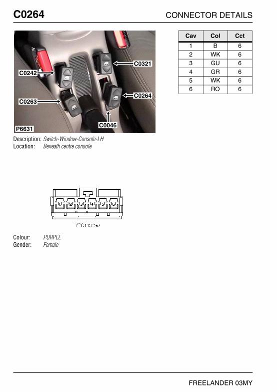
C0264 CONNECTOR DETAILS
FREELANDER 03MY
C0264
Description: Switch-Window-Console-LHLocation: Beneath centre console
Colour: PURPLEGender: Female
P6631
C0242
C0321
C0264
C0046
C0263
Cav Col Cct
1 B 62 WK 63 GU 6
4 GR 65 WK 66 RO 6

CONNECTOR DETAILS C0268
FREELANDER 03MY
C0268
Description: Solenoid-Shift-InterlockLocation: Beneath centre console
Colour: BLACKGender: Female
P6656
C0908
C0410
C0268
Cav Col Cct
1 GW 233 B 23

C0275 CONNECTOR DETAILS
FREELANDER 03MY
C0275
Description: Switch pack-Air conditioning (A/C)Location: Behind centre console
Colour: BLACKGender: Female
P6786
C0047C0223
C0275
C0067C0229
Cav Col Cct
1 B ALL2 BO ALL3 RO ALL
4 B ALL5 B ALL5 BO ALL

CONNECTOR DETAILS C0276
FREELANDER 03MY
C0276
Description: Ignition coil-3 - KV6Location: Top of engine
Colour: BLACKGender: Female
P7083
C1771C0276
C0526
C0524
C0522
C0156
Cav Col Cct
1 BW ALL2 B ALL3 NK ALL
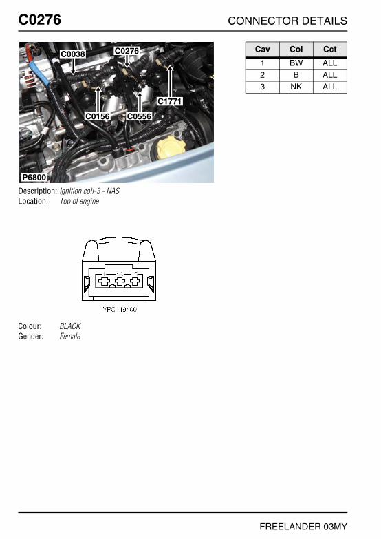
C0276 CONNECTOR DETAILS
FREELANDER 03MY
C0276
Description: Ignition coil-3 - NASLocation: Top of engine
Colour: BLACKGender: Female
P6800
C0038 C0276
C0556C0156
C1771
Cav Col Cct
1 BW ALL2 B ALL3 NK ALL

CONNECTOR DETAILS C0285
FREELANDER 03MY
C0285
Description: HeaderLocation: Behind centre of fascia
Colour: BLUEGender: Female
P6828
C0285
Cav Col Cct
1 GR ALL2 GR ALL3 GR 23
4 G ALL5 G 237 P ALL
8 P ALL9 P ALL
10 NS ALL
11 WO ALL12 WO ALL13 WO 16
14 WO ALL15 B ALL16 B ALL
17 B ALL18 B 2819 B ALL
20 B 17

C0286 CONNECTOR DETAILS
FREELANDER 03MY
C0286
Description: HeaderLocation: Behind LH side of fascia
Colour: BLUEGender: Female
P6830
C0292 C0286
C0075
C0787
C0652
Cav Col Cct
1 RO ALL2 RO ALL2 RB 3
3 RO 23 RB 34 RO 28
5 WR ALL6 WR 168 NK 23
9 NK 2610 NK 2311 GN ALL
12 GN ALL13 GN ALL17 GP ALL
18 GP 1619 GP 1620 GP ALL

CONNECTOR DETAILS C0290
FREELANDER 03MY
C0290
Description: HeaderLocation: Behind centre console
Colour: BLUEGender: Female
P6826
C0550
C0420C1023
C0417
C0294
C0290
C0153
Cav Col Cct
1 RO ALL2 RO ALL3 RO ALL
4 RO 65 RO 346 RO 34
7 RO 68 RO ALL9 SG 6
10 SG 611 SG 613 RO ALL
14 RO ALL15 RO 616 RO ALL
17 RO ALL18 RO ALL19 RO ALL
20 RO ALL

C0292 CONNECTOR DETAILS
FREELANDER 03MY
C0292
Description: HeaderLocation: Behind centre of fascia
Colour: BLUEGender: Female
P6830
C0292 C0286
C0075
C0787
C0652
Cav Col Cct
1 K ALL2 K ALL3 K ALL
5 K ALL6 K ALL7 K ALL
8 K 239 NG 23
10 NG 23
11 NG 2312 NG 2313 W ALL
14 W 1615 W ALL16 W 23
17 W ALL18 W ALL19 W 23
20 W ALL

CONNECTOR DETAILS C0294
FREELANDER 03MY
C0294
Description: HeaderLocation: Behind centre console
Colour: BLUEGender: Female
P6826
C0550
C0420C1023
C0417
C0294
C0290
C0153
Cav Col Cct
1 B ALL2 B ALL3 B 26
4 B ALL5 B ALL6 B ALL
7 B ALL8 B 349 B 34
10 B 3411 B 3412 B 34
13 B 614 B ALL15 B 6
16 B 617 B 2318 B ALL
19 B ALL20 B ALL

C0294 CONNECTOR DETAILS
FREELANDER 03MY
C0294
Description: Header - NASLocation: Inside E-box
Colour: GREYGender: Female
NO PHOTO LOCATION
Cav Col Cct
2 YG ALL4 YG ALL5 YG ALL
6 YG ALL7 YG ALL8 YG ALL
9 YG ALL10 YG ALL11 YG ALL
13 NK ALL14 NK ALL15 NK ALL
16 NK ALL17 NK ALL18 NK ALL
19 NK ALL

CONNECTOR DETAILS C0296
FREELANDER 03MY
C0296
Description: HeaderLocation: Behind RH side of fascia
Colour: BLUEGender: Female
P6831
C0296
Cav Col Cct
5 YN 266 YN ALL7 YB 26
12 YN 2613 YB ALL14 YB 26
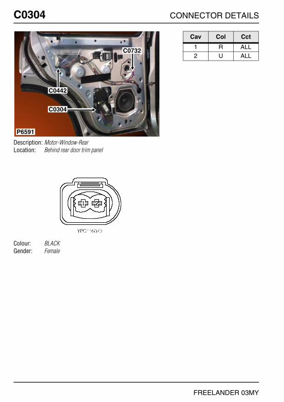
C0304 CONNECTOR DETAILS
FREELANDER 03MY
C0304
Description: Motor-Window-RearLocation: Behind rear door trim panel
Colour: BLACKGender: Female
P6591
C0442
C0732
C0304
Cav Col Cct
1 R ALL2 U ALL
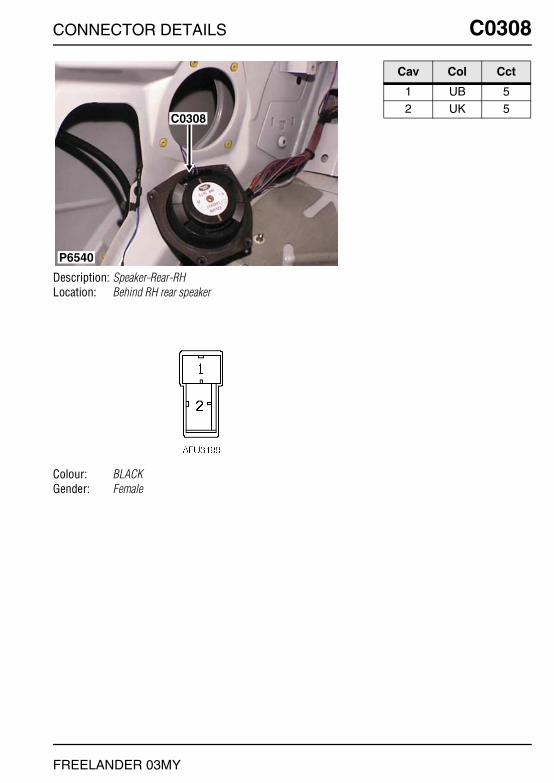
CONNECTOR DETAILS C0308
FREELANDER 03MY
C0308
Description: Speaker-Rear-RHLocation: Behind RH rear speaker
Colour: BLACKGender: Female
P6540
C0308
Cav Col Cct
1 UB 52 UK 5
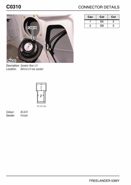
C0310 CONNECTOR DETAILS
FREELANDER 03MY
C0310
Description: Speaker-Rear-LHLocation: Behind LH rear speaker
Colour: BLACKGender: Female
P6532
C0310
Cav Col Cct
1 SK 52 SB 5

CONNECTOR DETAILS C0319
FREELANDER 03MY
C0319
Description: Mirror-Door - 3 DoorLocation: Behind front door trim panel
Colour: BLACKGender: Female
P6568
C0319
C0531
C0530
Cav Col Cct
1 BP ALL2 SW ALL3 NG ALL
4 B ALL5 BN ALL

C0319 CONNECTOR DETAILS
FREELANDER 03MY
C0319
Description: Mirror-Door - 5 DoorLocation: Behind front door trim panel
Colour: BLACKGender: Female
P6641
C0444
C0530C0531
C0319
Cav Col Cct
1 BP ALL2 SW ALL3 NG ALL
4 B ALL5 BN ALL

CONNECTOR DETAILS C0320
FREELANDER 03MY
C0320
Description: Switch-Wiper-FrontLocation: RH side of steering column
Colour: NATURALGender: Female
P6645
C0320
C0035
Cav Col Cct
4 WK ALL6 GY ALL

C0321 CONNECTOR DETAILS
FREELANDER 03MY
C0321
Description: Switch-Window-Front-LHLocation: In rear of centre console
Colour: WHITEGender: Female
P6631
C0242
C0321
C0264
C0046
C0263
Cav Col Cct
1 B ALL2 RG ALL3 OY 2
3 U 34 OG 24 R 3
6 RO ALL

CONNECTOR DETAILS C0326
FREELANDER 03MY
C0326
Description: Motor-Window-Front - 3 DoorLocation: Behind front door trim panel
Colour: BLACKGender: Female
P6569
C0441C0326
Cav Col Cct
1 OR ALL2 OU ALL

C0326 CONNECTOR DETAILS
FREELANDER 03MY
C0326
Description: Motor-Window-Front - 5 DoorLocation: Behind front door trim panel
Colour: BLACKGender: Female
P6640
C0441
C0326
Cav Col Cct
1 OR ALL2 OU ALL
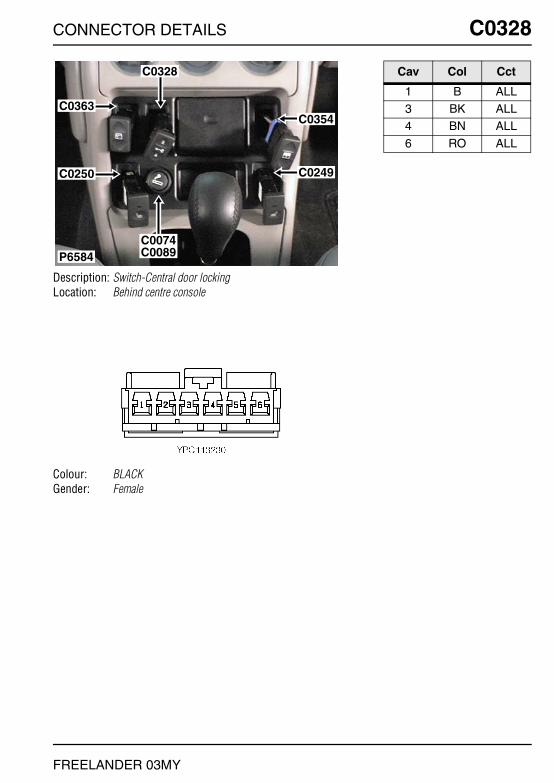
CONNECTOR DETAILS C0328
FREELANDER 03MY
C0328
Description: Switch-Central door lockingLocation: Behind centre console
Colour: BLACKGender: Female
P6584
C0328
C0074C0089
C0363
C0250
C0354
C0249
Cav Col Cct
1 B ALL3 BK ALL4 BN ALL
6 RO ALL
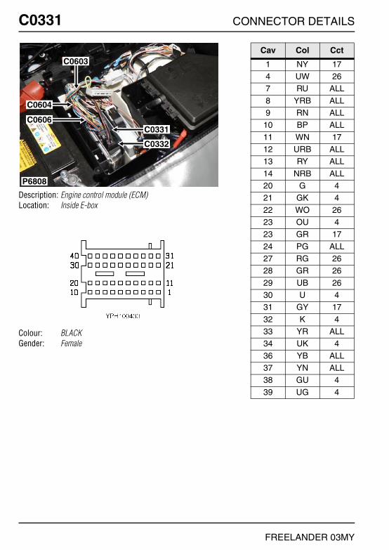
C0331 CONNECTOR DETAILS
FREELANDER 03MY
C0331
Description: Engine control module (ECM)Location: Inside E-box
Colour: BLACKGender: Female
P6808
C0603
C0331
C0332
C0604
C0606
Cav Col Cct
1 NY 174 UW 267 RU ALL
8 YRB ALL9 RN ALL
10 BP ALL
11 WN 1712 URB ALL13 RY ALL
14 NRB ALL20 G 421 GK 4
22 WO 2623 OU 423 GR 17
24 PG ALL27 RG 2628 GR 26
29 UB 2630 U 431 GY 17
32 K 433 YR ALL34 UK 4
36 YB ALL37 YN ALL38 GU 4
39 UG 4

CONNECTOR DETAILS C0332
FREELANDER 03MY
C0332
Description: Engine control module (ECM) - Td4Location: Inside E-box
Colour: BLACKGender: Female
P7086
C0160C0450
C0646
C1258
C0603
C0604
C0606
C0331C0332
Cav Col Cct
1 RU ALL3 NW ALL4 RU ALL
5 NW ALL7 NW ALL9 NW ALL

C0332 CONNECTOR DETAILS
FREELANDER 03MY
C0332
Description: Engine control module (ECM) - NASLocation: Inside E-box
Colour: GREYGender: Female
P6808
C0603
C0331
C0332
C0604
C0606
Cav Col Cct
1 BP ALL2 BW ALL3 BR ALL
5 B ALL6 B ALL7 BY ALL
8 BU ALL9 BG ALL

CONNECTOR DETAILS C0341
FREELANDER 03MY
C0341
Description: ECU-Window liftLocation: Behind driver side of fascia
Colour: BLACKGender: Female
P6554
C0084C0610
C0349C0421
C0341
Cav Col Cct
2 OY ALL4 OG ALL5 B ALL
6 RG 26 SO 37 U 2
7 OU 39 R 29 OR 3
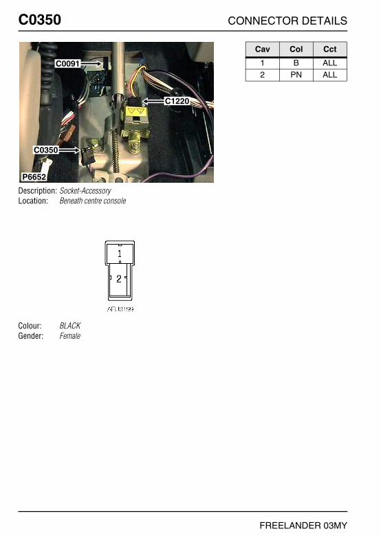
C0350 CONNECTOR DETAILS
FREELANDER 03MY
C0350
Description: Socket-AccessoryLocation: Beneath centre console
Colour: BLACKGender: Female
P6652
C0091
C0350
C1220
Cav Col Cct
1 B ALL2 PN ALL

CONNECTOR DETAILS C0354
FREELANDER 03MY
C0354
Description: Switch-Window-Tail doorLocation: Behind centre console
Colour: GREENGender: Female
P6584
C0328
C0074C0089
C0363
C0250
C0354
C0249
Cav Col Cct
1 B ALL3 BR ALL4 BK ALL
6 RO ALL

C0355 CONNECTOR DETAILS
FREELANDER 03MY
C0355
Description: Lamp-Interior-FrontLocation: Front of headlining in the centre
Colour: BLACKGender: Female
C0619
C0355
C0614
P6589
Cav Col Cct
1 B ALL3 P ALL4 PW 6

CONNECTOR DETAILS C0356
FREELANDER 03MY
C0356
Description: Lamp-Interior-RearLocation: Behind centre headlining
Colour: BLACKGender: Female
P6590
C0356
Cav Col Cct
1 P ALL2 PW 63 B ALL

C0357 CONNECTOR DETAILS
FREELANDER 03MY
C0357
Description: Switch-Interior lamp-RearLocation: Behind centre headlining
Colour: NATURALGender: Female
P6541
C0611
C0357
Cav Col Cct
1 PW 53 P ALL
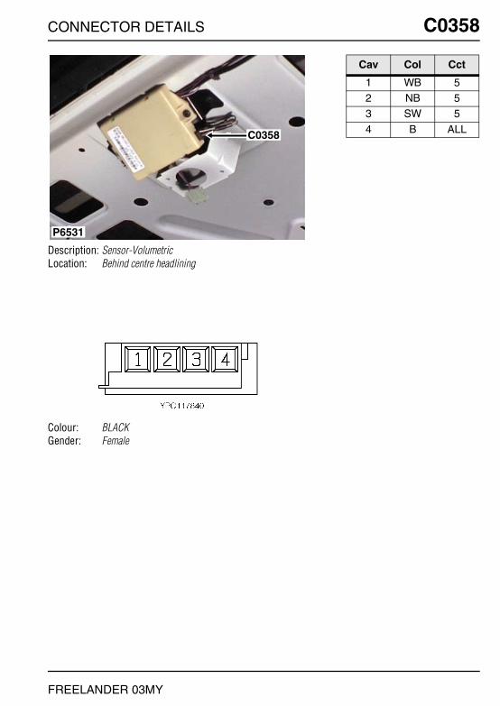
CONNECTOR DETAILS C0358
FREELANDER 03MY
C0358
Description: Sensor-VolumetricLocation: Behind centre headlining
Colour: BLACKGender: Female
P6531
C0358
Cav Col Cct
1 WB 52 NB 53 SW 5
4 B ALL

C0359 CONNECTOR DETAILS
FREELANDER 03MY
C0359
Description: Receiver-Radio frequency (RF)Location: Behind instrument pack
Colour: BLACKGender: Female
P6839
C0359
C1000
C0230
C0719
C0233
Cav Col Cct
1 S ALL2 B ALL3 Y ALL
4 B ALL

CONNECTOR DETAILS C0362
FREELANDER 03MY
C0362
Description: Earth-ABSLocation: Front RH side of engine compartment
Colour: TIN-PLATEGender: Eyelet
P7090
C0362C0434
Cav Col Cct
1 B ALL

C0363 CONNECTOR DETAILS
FREELANDER 03MY
C0363
Description: Switch-Sunroof-FrontLocation: Behind centre console
Colour: BLUEGender: Female
P6584
C0328
C0074C0089
C0363
C0250
C0354
C0249
Cav Col Cct
1 B 62 SR ALL3 S ALL
4 G ALL6 RO 6
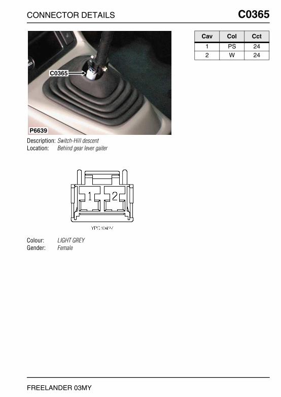
CONNECTOR DETAILS C0365
FREELANDER 03MY
C0365
Description: Switch-Hill descentLocation: Behind gear lever gaiter
Colour: LIGHT GREYGender: Female
P6639
C0365
Cav Col Cct
1 PS 242 W 24

C0369 CONNECTOR DETAILS
FREELANDER 03MY
C0369
Description: Speakers-Front - 3 DoorLocation: Behind front door trim panel
Colour: BLACKGender: Female
P6578
C0369
Cav Col Cct
1 OB 82 OK 8
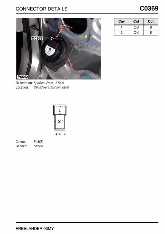
CONNECTOR DETAILS C0369
FREELANDER 03MY
C0369
Description: Speakers-Front - 5 DoorLocation: Behind front door trim panel
Colour: BLACKGender: Female
C0369
P6642
Cav Col Cct
1 OB 82 OK 8

C0371 CONNECTOR DETAILS
FREELANDER 03MY
C0371
Description: Engine control module (ECM)Location: Inside E-box
Colour: BLACKGender: Female
P6649
C0293
C0371C0932
Cav Col Cct
1 BY ALL2 BW ALL3 B ALL
4 BO ALL5 Y ALL6 U ALL
7 WK ALL8 SB ALL9 BP ALL
10 BU ALL12 BS ALL13 GY ALL
14 UY ALL15 KB ALL16 OY ALL
17 UG ALL18 BS ALL19 BS ALL
20 BO ALL21 WO ALL23 UK ALL
27 YB ALL28 B ALL29 W ALL
30 NP ALL31 BU ALL32 BP ALL
33 B ALL34 UN ALL35 UW ALL
36 GN ALL38 OY ALL42 KU ALL
44 BLG ALL45 KG ALL46 GU ALL
47 KO ALL

CONNECTOR DETAILS C0371
FREELANDER 03MY
48 R ALL49 UY ALL
50 LGS ALL51 GK ALL52 YR ALL
53 PB ALL54 WU ALL56 K ALL
57 YN ALL58 YR ALL59 YN ALL
60 Y ALL61 BR ALL62 BG ALL
63 B ALL64 BR ALL66 NK ALL
67 B ALL69 UR ALL70 OU ALL
71 OG ALL72 OS ALL73 GW ALL
74 GU ALL75 KB ALL76 BG ALL
77 BG ALL78 YW ALL80 BK ALL
81 UO ALL82 UG ALL84 OU ALL
85 BS ALL88 YU ALL89 YP ALL
90 YG ALL
Cav Col Cct

C0374 CONNECTOR DETAILS
FREELANDER 03MY
C0374
Description: Rotary couplerLocation: Underside of steering column
Colour: YELLOWGender: Female
P6643
C0374
C0082
C0028
C0049
Cav Col Cct
1 R ALL2 Y ALL

CONNECTOR DETAILS C0381
FREELANDER 03MY
C0381
Description: Heated rear window (HRW)Location: LH side of taildoor
Colour: BLACKGender: Female
C0381 C0382
P6526
Cav Col Cct
1 N 38

C0382 CONNECTOR DETAILS
FREELANDER 03MY
C0382
Description: Heated rear window (HRW)Location: LH side of taildoor
Colour: BLACKGender: Female
C0381 C0382
P6526
Cav Col Cct
1 B 38

CONNECTOR DETAILS C0384
FREELANDER 03MY
C0384
Description: Tail door harness to main harnessLocation: Rear of luggage compartment - RH side
Colour: BROWNGender: Male
C0473
C0122C0386
C0144C0385
C0117C0384
C0551
P7082
Cav Col Cct
1 UB 382 UG 383 N 38
4 B 385 G 38

C0385 CONNECTOR DETAILS
FREELANDER 03MY
C0385
Description: Tail door harness to main harnessLocation: Rear of luggage compartment - RH side
Colour: LIGHT GREYGender: Male
C0473
C0122C0386
C0144C0385
C0117C0384
C0551
P7082
Cav Col Cct
1 KB 383 SR 384 SP 38
5 US 386 NG 38

CONNECTOR DETAILS C0386
FREELANDER 03MY
C0386
Description: Tail door harness to main harnessLocation: Rear of luggage compartment - RH side
Colour: LIGHT GREYGender: Male
C0473
C0122C0386
C0144C0385
C0117C0384
C0551
P7082
Cav Col Cct
1 ON ALL2 BO ALL3 RO ALL
4 PU ALL5 GP ALL6 B ALL
7 GR 388 OB 38

C0388 CONNECTOR DETAILS
FREELANDER 03MY
C0388
Description: Motor-Wiper-Rear screenLocation: Centre of taildoor, behind trim panel
Colour: BLACKGender: Female
C0388
C0612
P6524
Cav Col Cct
1 GR 382 G 383 NG 38
4 OB 385 B 38

CONNECTOR DETAILS C0396
FREELANDER 03MY
C0396
Description: Main harness to door harnessLocation: Base of passenger side 'A' post
Colour: BLACKGender: Male
P7087
C0809C0808
C0439C0396
C0397C0440
C0811C1355
C1971C1412
Cav Col Cct
1 BR 32 BK 33 PS 3
3 PW ALL4 O ALL5 Y ALL
6 OB ALL7 OK ALL8 SW ALL
9 NG ALL10 BN ALL11 BP ALL

C0397 CONNECTOR DETAILS
FREELANDER 03MY
C0397
Description: Main harness to door harnessLocation: Base of passenger side 'A' post
Colour: LIGHT GREYGender: Male
P7087
C0809C0808
C0439C0396
C0397C0440
C0811C1355
C1971C1412
Cav Col Cct
1 OR ALL2 OU ALL3 NK ALL
4 B ALL5 O ALL6 K ALL

CONNECTOR DETAILS C0398
FREELANDER 03MY
C0398
Description: Main harness to door harnessLocation: Base of passenger side 'A' post
Colour: BLACKGender: Male
P6553
C0723
C0398C0439
C0399C0440
Cav Col Cct
1 BR 22 BK 23 PS 2
3 PW ALL4 Y ALL5 O ALL
6 YB ALL7 YK ALL8 SW ALL
9 NG ALL10 BU ALL11 BY ALL

C0399 CONNECTOR DETAILS
FREELANDER 03MY
C0399
Description: Main harness to door harnessLocation: Base of passenger side 'A' post
Colour: LIGHT GREYGender: Male
P6553
C0723
C0398C0439
C0399C0440
Cav Col Cct
1 R ALL2 U ALL3 NK ALL
4 B ALL5 O ALL6 K ALL

CONNECTOR DETAILS C0410
FREELANDER 03MY
C0410
Description: Switch-SteptronicLocation: Beneath centre console
Colour: BLACKGender: Female
P6656
C0908
C0410
C0268
Cav Col Cct
1 NK 232 B 237 GB 23
8 GK 239 LGK 23

C0417 CONNECTOR DETAILS
FREELANDER 03MY
C0417
Description: Sensor-EvaporatorLocation: Behind centre console
Colour: LIGHT GREYGender: Male
P6826
C0550
C0420C1023
C0417
C0294
C0290
C0153
Cav Col Cct
1 GU 161 GO ALL2 PB 16
2 B 262 BO 32

CONNECTOR DETAILS C0420
FREELANDER 03MY
C0420
Description: Heated front screen harness to main harnessLocation: Rear LH side of engine compartment
Colour: GREYGender: Male
C0420C1704
P6810
Cav Col Cct
1 SB ALL2 PG ALL

C0420 CONNECTOR DETAILS
FREELANDER 03MY
C0420
Description: PTC heater harness to main harnessLocation: Beneath engine compartment fusebox
Colour: GREYGender: Male
P7093
C0420C0483
C0157
C1875
Cav Col Cct
1 G ALL2 GR ALL3 GY ALL
4 B ALL5 GW ALL

CONNECTOR DETAILS C0420
FREELANDER 03MY
C0420
Description: Link harness to main harnessLocation: Beneath engine compartment fusebox
Colour: GREYGender: Male
P7102
C0420C0167
Cav Col Cct
1 GN ALL2 G ALL

C0420 CONNECTOR DETAILS
FREELANDER 03MY
C0420
Description: Audio system harness to main harnessLocation: Behind centre console
Colour: LIGHT GREYGender: Male
P6826
C0550
C0420C1023
C0417
C0294
C0290
C0153
Cav Col Cct
1 YK ALL2 OK ALL3 SK ALL
4 LGW ALL5 UK ALL6 YB ALL
7 P ALL7 PK ALL8 BW ALL
9 OB ALL10 SB ALL11 RO ALL
12 UB ALL13 B ALL14 BR ALL
15 WO 1216 GN 1217 SB ALL
18 SN ALL19 SW ALL20 SR ALL

CONNECTOR DETAILS C0421
FREELANDER 03MY
C0421
Description: Roof harness to main harnessLocation: Behind driver side of fascia
Colour:Gender:
P6554
C0084C0610
C0349C0421
C0341
Cav Col Cct
1 B ALL2 SCR ALL
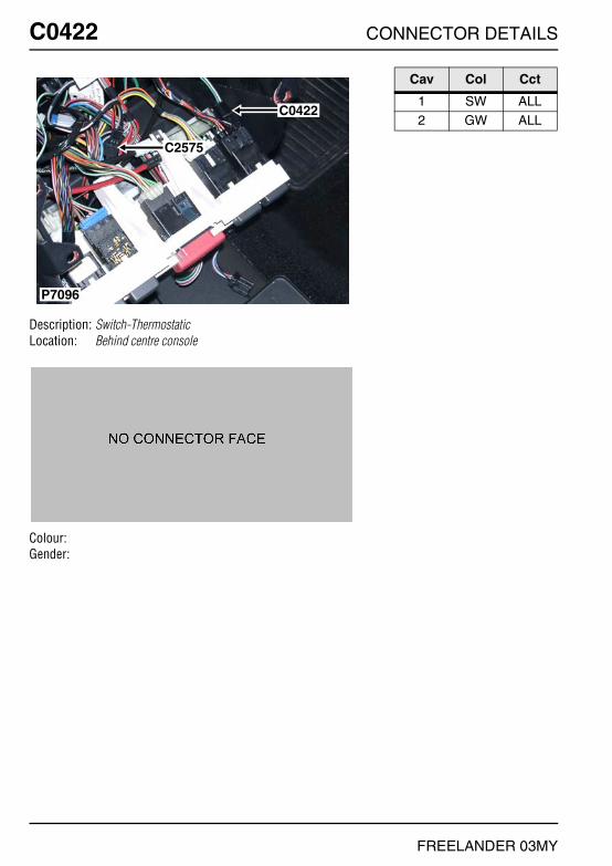
C0422 CONNECTOR DETAILS
FREELANDER 03MY
C0422
Description: Switch-ThermostaticLocation: Behind centre console
Colour:Gender:
C0422
C2575
P7096
Cav Col Cct
1 SW ALL2 GW ALL

CONNECTOR DETAILS C0425
FREELANDER 03MY
C0425
Description: Resistor packLocation: Behind centre of fascia
Colour:Gender:
C0425
P6829
Cav Col Cct
1 GK ALL2 RY ALL3 RK ALL
4 RG ALL

C0428 CONNECTOR DETAILS
FREELANDER 03MY
C0428
Description: Central Control Unit (CCU)Location: Behind passenger compartment fusebox
Colour: GREYGender: Female
P6551
C0430
C0429 C0428
Cav Col Cct
1 GB ALL2 LGB ALL3 G ALL
4 GN ALL5 NG ALL6 NB ALL
7 BR ALL8 BK ALL9 RW ALL
10 BR ALL11 BK ALL12 US ALL
13 PY 514 ON ALL15 U ALL
16 UG ALL17 OB ALL18 ON ALL
19 BK ALL20 BN ALL21 PW ALL
22 RP ALL23 BO ALL24 PS ALL
25 WO ALL26 S ALL

CONNECTOR DETAILS C0429
FREELANDER 03MY
C0429
Description: Central Control Unit (CCU)Location: Behind passenger compartment fusebox
Colour: LIGHT GREYGender: Female
P6551
C0430
C0429 C0428
Cav Col Cct
1 RG ALL2 WB ALL3 RU ALL
4 YW ALL5 YB ALL6 WK ALL
7 G ALL8 SW ALL9 Y ALL
10 SB 2811 KO 2812 SP ALL
13 SR ALL14 K ALL15 KN ALL
16 GY ALL
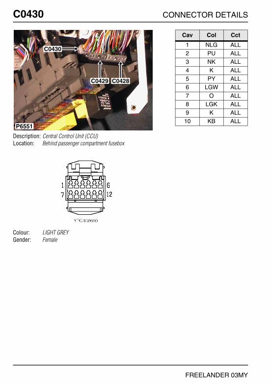
C0430 CONNECTOR DETAILS
FREELANDER 03MY
C0430
Description: Central Control Unit (CCU)Location: Behind passenger compartment fusebox
Colour: LIGHT GREYGender: Female
P6551
C0430
C0429 C0428
Cav Col Cct
1 NLG ALL2 PU ALL3 NK ALL
4 K ALL5 PY ALL6 LGW ALL
7 O ALL8 LGK ALL9 K ALL
10 KB ALL

CONNECTOR DETAILS C0431
FREELANDER 03MY
C0431
Description: Main harness to heater harnessLocation: Behind centre console
Colour: BROWNGender: Female
P7080
C0015C0431C0010
C0906
Cav Col Cct
1 GN ALL2 RO ALL3 SK ALL
4 B ALL5 G ALL

C0433 CONNECTOR DETAILS
FREELANDER 03MY
C0433
Description: Air bag-PassengerLocation: Behind passenger's airbag module
Colour: REDGender: Female
C0433
P6821
Cav Col Cct
1 W ALL2 U ALL

CONNECTOR DETAILS C0434
FREELANDER 03MY
C0434
Description: Earth-ABS modulatorLocation: Front RH side of engine compartment
Colour: TIN-PLATEGender: Eyelet
P7090
C0362C0434
Cav Col Cct
1 B ALL
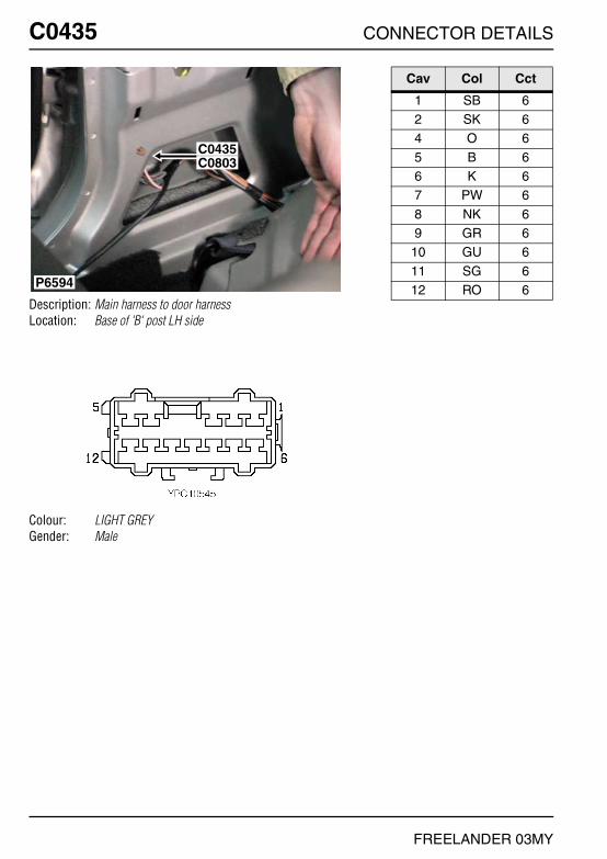
C0435 CONNECTOR DETAILS
FREELANDER 03MY
C0435
Description: Main harness to door harnessLocation: Base of 'B' post LH side
Colour: LIGHT GREYGender: Male
P6594
C0435C0803
Cav Col Cct
1 SB 62 SK 64 O 6
5 B 66 K 67 PW 6
8 NK 69 GR 6
10 GU 6
11 SG 612 RO 6
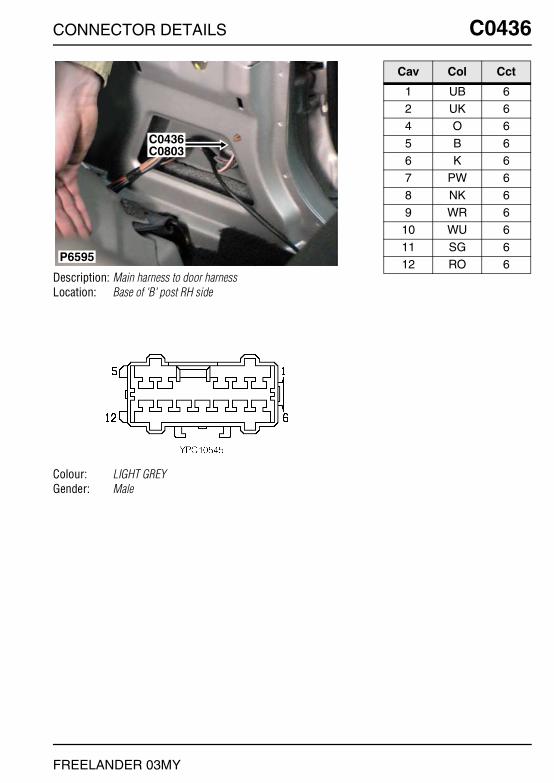
CONNECTOR DETAILS C0436
FREELANDER 03MY
C0436
Description: Main harness to door harnessLocation: Base of 'B' post RH side
Colour: LIGHT GREYGender: Male
C0436C0803
P6595
Cav Col Cct
1 UB 62 UK 64 O 6
5 B 66 K 67 PW 6
8 NK 69 WR 6
10 WU 6
11 SG 612 RO 6

C0439 CONNECTOR DETAILS
FREELANDER 03MY
C0439
Description: Door harness to main harness - 3 DoorLocation: Base of driver side 'A' post
Colour: BLACKGender: Female
P6553
C0723
C0398C0439
C0399C0440
Cav Col Cct
1 BR ALL2 BK ALL3 PW ALL
4 R 75 B 76 OB ALL
7 OK ALL8 SW ALL9 NG ALL
10 BN ALL11 BP ALL

CONNECTOR DETAILS C0439
FREELANDER 03MY
C0439
Description: Door harness to main harness - 5 DoorLocation: Base of driver side 'A' post
Colour: BLACKGender: Female
P6553
C0723
C0398C0439
C0399C0440
Cav Col Cct
1 BR ALL2 BK ALL3 PW ALL
4 R 75 B 76 OB ALL
7 OK ALL8 SW ALL9 NG ALL
10 BN ALL11 BP ALL
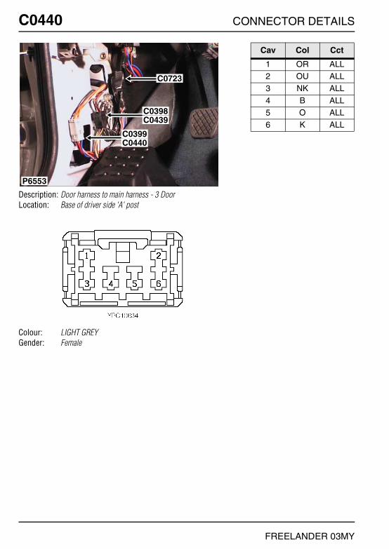
C0440 CONNECTOR DETAILS
FREELANDER 03MY
C0440
Description: Door harness to main harness - 3 DoorLocation: Base of driver side 'A' post
Colour: LIGHT GREYGender: Female
P6553
C0723
C0398C0439
C0399C0440
Cav Col Cct
1 OR ALL2 OU ALL3 NK ALL
4 B ALL5 O ALL6 K ALL

CONNECTOR DETAILS C0440
FREELANDER 03MY
C0440
Description: Door harness to main harness - 5 DoorLocation: Base of driver side 'A' post
Colour: LIGHT GREYGender: Female
P6553
C0723
C0398C0439
C0399C0440
Cav Col Cct
1 OR ALL2 OU ALL3 NK ALL
4 B ALL5 O ALL6 K ALL

C0441 CONNECTOR DETAILS
FREELANDER 03MY
C0441
Description: Motor-Door lock-Front - 3 DoorLocation: Behind front door trim panel
Colour: BLACKGender: Female
P6569
C0441C0326
Cav Col Cct
1 BK ALL3 BR ALL4 K ALL
5 B ALL6 PW ALL7 O ALL
8 NK ALL

CONNECTOR DETAILS C0441
FREELANDER 03MY
C0441
Description: Motor-Door lock-Front - 5 DoorLocation: Behind front door trim panel
Colour: BLACKGender: Female
P6640
C0441
C0326
Cav Col Cct
1 BK ALL3 BR ALL4 K ALL
5 B ALL6 PW ALL7 O ALL
8 NK ALL

C0442 CONNECTOR DETAILS
FREELANDER 03MY
C0442
Description: Motor-Door lock-RearLocation: Behind rear door trim panel
Colour: BLACKGender: Female
P6591
C0442
C0732
C0304
Cav Col Cct
4 K ALL5 B ALL6 PW ALL
7 O ALL8 NK ALL

CONNECTOR DETAILS C0444
FREELANDER 03MY
C0444
Description: Mirror-Door - 3 DoorLocation: Behind front door trim panel
Colour: BLACKGender: Female
P6641
C0444
C0530C0531
C0319
Cav Col Cct
1 R 72 B 7

C0444 CONNECTOR DETAILS
FREELANDER 03MY
C0444
Description: Mirror-Door - 5 DoorLocation: Behind front door trim panel
Colour: BLACKGender: Female
P6641
C0444
C0530C0531
C0319
Cav Col Cct
1 R 72 B 7

CONNECTOR DETAILS C0445
FREELANDER 03MY
C0445
Description: Speakers-RearLocation: Behind rear door trim panel
Colour: BLACKGender: Female
P6592
C0445
Cav Col Cct
1 UB 82 UK 8

C0448 CONNECTOR DETAILS
FREELANDER 03MY
C0448
Description: Main harness to engine harnessLocation: Inside E-box
Colour: LIGHT GREYGender: Female
P6618
C0914
C0162C0448
C0913
Cav Col Cct
1 G 182 GN 183 RW 18
4 B 185 KB 186 LGS 18
7 GU 188 GO 329 BO 32
12 NR 18

CONNECTOR DETAILS C0450
FREELANDER 03MY
C0450
Description: Main harness to engine harnessLocation: Inside E-box
Colour: BLACKGender: Male
P7086
C0160C0450
C0646
C1258
C0603
C0604
C0606
C0331C0332
Cav Col Cct
1 NR 172 BY 173 BR 17
6 W 178 BP 179 BG 17
11 BR 1712 RW 17

C0451 CONNECTOR DETAILS
FREELANDER 03MY
C0451
Description: Main harness to engine harnessLocation: Inside E-box
Colour: LIGHT GREYGender: Female
P6809
C0646C0200C0451
C0932
C1258
Cav Col Cct
1 NK 42 BG 43 OU 4
4 GK 45 UK 4

CONNECTOR DETAILS C0455
FREELANDER 03MY
C0455
Description: Lamp-Reverse-RHLocation: RH rear of vehicle
Colour: WHITEGender: Female
P6840
C0455
C0489
Cav Col Cct
1 B ALL2 GN ALL

C0472 CONNECTOR DETAILS
FREELANDER 03MY
C0472
Description: Lamp-Reverse-LHLocation: LH rear of vehicle
Colour: WHITEGender: Female
P6841
C0490
C0472
Cav Col Cct
1 B ALL2 GN ALL

CONNECTOR DETAILS C0473
FREELANDER 03MY
C0473
Description: Main harness to trailer harnessLocation: Rear of luggage compartment - RH side
Colour: WHITEGender: Male
C0473
C0122C0386
C0144C0385
C0117C0384
C0551
P7082
Cav Col Cct
1 GR ALL2 RY ALL3 GW ALL
4 B ALL5 RB ALL6 GP ALL
7 RO ALL

C0476 CONNECTOR DETAILS
FREELANDER 03MY
C0476
Description: Glow plug - Td4Location: Top of engine
Colour: BLACKGender: Female
P6629
C0476 C0477 C0478 C0479
Cav Col Cct
1 BG ALL

CONNECTOR DETAILS C0477
FREELANDER 03MY
C0477
Description: Glow plug - Td4Location: Top of engine
Colour: BLACKGender: Female
P6629
C0476 C0477 C0478 C0479
Cav Col Cct
1 BP ALL

C0478 CONNECTOR DETAILS
FREELANDER 03MY
C0478
Description: Glow plug - Td4Location: Top of engine
Colour: BLACKGender: Female
P6629
C0476 C0477 C0478 C0479
Cav Col Cct
1 BY ALL
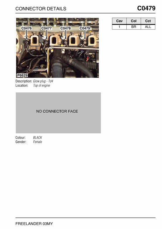
CONNECTOR DETAILS C0479
FREELANDER 03MY
C0479
Description: Glow plug - Td4Location: Top of engine
Colour: BLACKGender: Female
P6629
C0476 C0477 C0478 C0479
Cav Col Cct
1 BR ALL
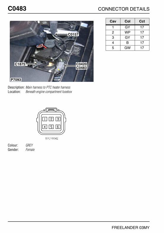
C0483 CONNECTOR DETAILS
FREELANDER 03MY
C0483
Description: Main harness to PTC heater harnessLocation: Beneath engine compartment fusebox
Colour: GREYGender: Female
P7093
C0420C0483
C0157
C1875
Cav Col Cct
1 GY 172 WP 173 GY 17
4 B 175 GW 17

CONNECTOR DETAILS C0489
FREELANDER 03MY
C0489
Description: Lamp-Tail-RHLocation: RH rear of vehicle
Colour: REDGender: Female
P6840
C0455
C0489
Cav Col Cct
1 B 42 RY 43 RO 4

C0490 CONNECTOR DETAILS
FREELANDER 03MY
C0490
Description: Lamp-Tail-LHLocation: LH rear of vehicle
Colour: REDGender: Female
P6841
C0490
C0472
Cav Col Cct
1 B 42 RY 43 RB 4

CONNECTOR DETAILS C0491
FREELANDER 03MY
C0491
Description: Amplifier-Power-ICELocation: Beneath driver's seat
Colour: BLACKGender: Female
C0491
P6817
Cav Col Cct
1 SB ALL2 SN ALL3 YB ALL
4 YK ALL5 PK ALL8 BG ALL
9 BP ALL10 PY ALL13 UK ALL
15 PY ALL16 BO ALL17 BU ALL
20 WO 1221 UB ALL22 OB ALL
23 OK ALL24 SW ALL25 SR ALL
26 B ALL29 BR ALL30 BS ALL
31 SK ALL32 SB ALL37 BN ALL
38 BW ALL

C0497 CONNECTOR DETAILS
FREELANDER 03MY
C0497
Description: Switch-Roof onLocation: RH 'D' post
Colour: LIGHT GREYGender: Female
P6538
C0497
Cav Col Cct
1 PY 52 P 5

CONNECTOR DETAILS C0501
FREELANDER 03MY
C0501
Description: Modulator-ABSLocation: Front RH side of engine compartment
Colour: BLACKGender: Female
P6791
C0501
C0517
Cav Col Cct
1 NK ALL2 K ALL4 W ALL
6 PS ALL9 BW ALL
11 YB ALL
13 YN ALL15 YN ALL16 B ALL
24 U ALL26 Y ALL32 NR ALL
33 YB ALL34 Y ALL35 BR ALL
36 G ALL37 GB ALL38 GP ALL
39 WO ALL40 R ALL41 GR ALL
42 WB ALL43 W ALL44 YB ALL
45 R ALL46 RB ALL47 B ALL

C0502 CONNECTOR DETAILS
FREELANDER 03MY
C0502
Description: Sensor-ABS-Rear-LHLocation: Below LH rear wheelarch
Colour: BLUEGender: Female
P6658
C0502
Cav Col Cct
1 G ALL2 GB ALL
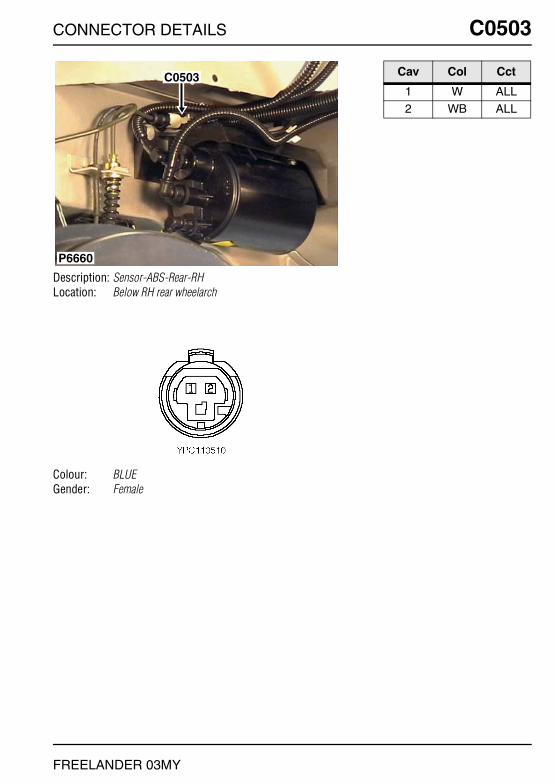
CONNECTOR DETAILS C0503
FREELANDER 03MY
C0503
Description: Sensor-ABS-Rear-RHLocation: Below RH rear wheelarch
Colour: BLUEGender: Female
P6660
C0503 Cav Col Cct
1 W ALL2 WB ALL
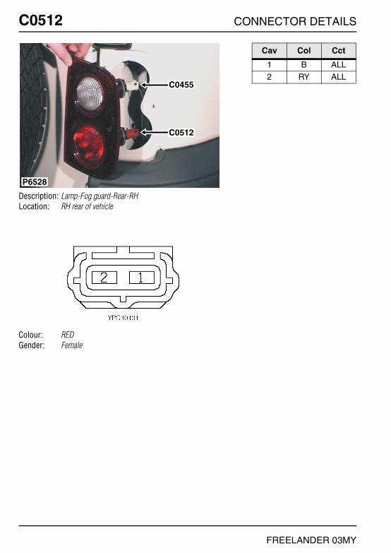
C0512 CONNECTOR DETAILS
FREELANDER 03MY
C0512
Description: Lamp-Fog guard-Rear-RHLocation: RH rear of vehicle
Colour: REDGender: Female
P6528
C0455
C0512
Cav Col Cct
1 B ALL2 RY ALL

CONNECTOR DETAILS C0515
FREELANDER 03MY
C0515
Description: Lamp-Fog guard-Rear-LHLocation: LH rear of vehicle
Colour: REDGender: Female
P6522
C0515
C0472
Cav Col Cct
1 B ALL2 RY ALL
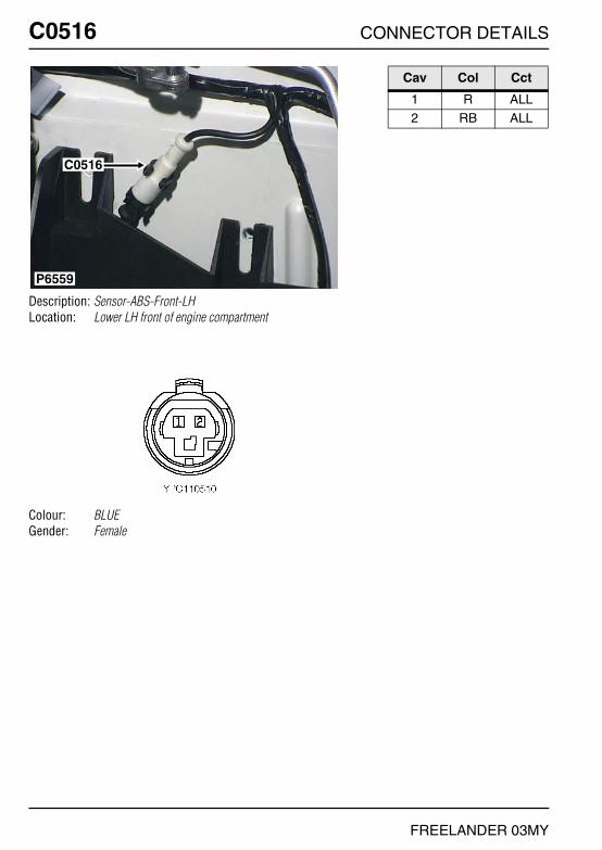
C0516 CONNECTOR DETAILS
FREELANDER 03MY
C0516
Description: Sensor-ABS-Front-LHLocation: Lower LH front of engine compartment
Colour: BLUEGender: Female
P6559
C0516
Cav Col Cct
1 R ALL2 RB ALL

CONNECTOR DETAILS C0517
FREELANDER 03MY
C0517
Description: Sensor-ABS-Front-RHLocation: Front RH side of engine compartment
Colour: BLUEGender: Female
P6791
C0501
C0517
Cav Col Cct
1 Y ALL2 YB ALL

C0521 CONNECTOR DETAILS
FREELANDER 03MY
C0521
Description: Injector harness to engine harness - K1.8Location: Top of engine
Colour: BLACKGender: Male
P6838
C0175
C0171C0521
C0176
C0164
C0567 Cav Col Cct
1 NK ALL2 YU ALL6 YG ALL
7 YR ALL8 KB ALL9 YW ALL
10 YN ALL11 NK ALL12 YP ALL
13 RG ALL15 WB ALL16 WO ALL

CONNECTOR DETAILS C0521
FREELANDER 03MY
C0521
Description: Injector harness to engine harness - KV6Location: Top of engine
Colour: BLACKGender: Male
P6842
C0521C0171
Cav Col Cct
1 YN ALL2 YR ALL3 YG ALL
4 NK ALL

C0522 CONNECTOR DETAILS
FREELANDER 03MY
C0522
Description: Fuel injector-No.1 - Td4Location: Top of engine
Colour: BLACKGender: Female
P6596
C0176
C0523
C0522
C0524
C0525
Cav Col Cct
1 RU ALL2 NW ALL

CONNECTOR DETAILS C0522
FREELANDER 03MY
C0522
Description: Fuel injector-No.1 - KV6Location: Top of engine
Colour: BLACKGender: Female
P7083
C1771C0276
C0526
C0524
C0522
C0156
Cav Col Cct
1 NK ALL2 Y ALL

C0522 CONNECTOR DETAILS
FREELANDER 03MY
C0522
Description: Fuel injector-No.1 - K1.8Location: Top of engine
Colour: BLACKGender: Female
P6614
C0522 C0523 C0524 C0525
C0567 C0177
Cav Col Cct
1 NK ALL2 YU ALL3 YG ALL

CONNECTOR DETAILS C0522
FREELANDER 03MY
C0522
Description: Fuel injector-No.1 - NASLocation: Top of engine
Colour: BLACKGender: Female
P6801
C0522
C0524C0526
Cav Col Cct
1 NK ALL2 Y ALL

C0523 CONNECTOR DETAILS
FREELANDER 03MY
C0523
Description: Fuel injector-No.2 - Td4Location: Top of engine
Colour: BLACKGender: Female
P6596
C0176
C0523
C0522
C0524
C0525
Cav Col Cct
1 RU ALL2 NW ALL

CONNECTOR DETAILS C0523
FREELANDER 03MY
C0523
Description: Fuel injector-No.2 - K1.8Location: Top of engine
Colour: BLACKGender: Female
P6614
C0522 C0523 C0524 C0525
C0567 C0177
Cav Col Cct
1 NK ALL2 YG ALL

C0523 CONNECTOR DETAILS
FREELANDER 03MY
C0523
Description: Fuel injector-No.2 - KV6Location: Top of engine
Colour: BLACKGender: Female
P6630
C0523
C0525 C0527
Cav Col Cct
1 NK ALL2 YN ALL

CONNECTOR DETAILS C0524
FREELANDER 03MY
C0524
Description: Fuel injector-No.3 - Td4Location: Top of engine
Colour: BLACKGender: Female
P6596
C0176
C0523
C0522
C0524
C0525
Cav Col Cct
1 RU ALL2 NW ALL

C0524 CONNECTOR DETAILS
FREELANDER 03MY
C0524
Description: Fuel injector-No.3 - KV6Location: Top of engine
Colour: BLACKGender: Female
P7083
C1771C0276
C0526
C0524
C0522
C0156
Cav Col Cct
1 NK ALL2 YU ALL

CONNECTOR DETAILS C0524
FREELANDER 03MY
C0524
Description: Fuel injector-No.3 - K1.8Location: Top of engine
Colour: BLACKGender: Female
P6614
C0522 C0523 C0524 C0525
C0567 C0177
Cav Col Cct
1 NK ALL2 YG ALL

C0524 CONNECTOR DETAILS
FREELANDER 03MY
C0524
Description: Fuel injector-No.3 - NASLocation: Top of engine
Colour: BLACKGender: Female
P6801
C0522
C0524C0526
Cav Col Cct
1 NK ALL2 YU ALL

CONNECTOR DETAILS C0525
FREELANDER 03MY
C0525
Description: Fuel injector-No.4 - Td4Location: Top of engine
Colour: BLACKGender: Female
P6596
C0176
C0523
C0522
C0524
C0525
Cav Col Cct
1 RU ALL2 NW ALL
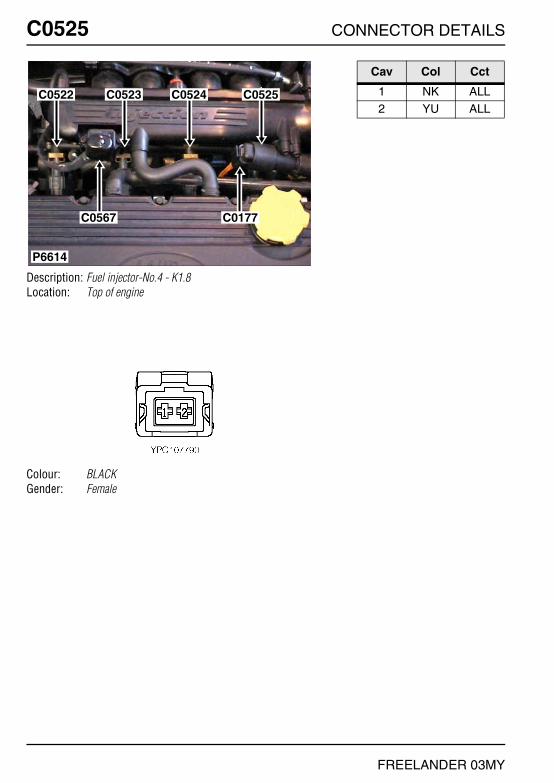
C0525 CONNECTOR DETAILS
FREELANDER 03MY
C0525
Description: Fuel injector-No.4 - K1.8Location: Top of engine
Colour: BLACKGender: Female
P6614
C0522 C0523 C0524 C0525
C0567 C0177
Cav Col Cct
1 NK ALL2 YU ALL

CONNECTOR DETAILS C0525
FREELANDER 03MY
C0525
Description: Fuel injector-No.4 - KV6Location: Top of engine
Colour: BLACKGender: Female
P6630
C0523
C0525 C0527
Cav Col Cct
1 NK ALL2 YR ALL

C0526 CONNECTOR DETAILS
FREELANDER 03MY
C0526
Description: Fuel injector-No.5 - KV6Location: Top of engine
Colour: BLACKGender: Female
P7083
C1771C0276
C0526
C0524
C0522
C0156
Cav Col Cct
1 NK ALL2 YP ALL

CONNECTOR DETAILS C0526
FREELANDER 03MY
C0526
Description: Fuel injector-No.5 - NASLocation: Top of engine
Colour: BLACKGender: Female
P6801
C0522
C0524C0526
Cav Col Cct
1 NK ALL2 YP ALL

C0527 CONNECTOR DETAILS
FREELANDER 03MY
C0527
Description: Fuel injector-No.6Location: Top of engine
Colour: BLACKGender: Female
P6630
C0523
C0525 C0527
Cav Col Cct
1 NK ALL2 YG ALL

CONNECTOR DETAILS C0530
FREELANDER 03MY
C0530
Description: Speakers-High Range - 3 DoorLocation: Behind front door trim panel
Colour: NATURALGender: Female
P6568
C0319
C0531
C0530
Cav Col Cct
1 OB 8
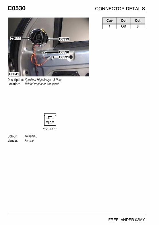
C0530 CONNECTOR DETAILS
FREELANDER 03MY
C0530
Description: Speakers-High Range - 5 DoorLocation: Behind front door trim panel
Colour: NATURALGender: Female
P6641
C0444
C0530C0531
C0319
Cav Col Cct
1 OB 8

CONNECTOR DETAILS C0531
FREELANDER 03MY
C0531
Description: Speakers-High Range - 3 DoorLocation: Behind front door trim panel
Colour: NATURALGender: Female
P6568
C0319
C0531
C0530
Cav Col Cct
1 OK 8

C0531 CONNECTOR DETAILS
FREELANDER 03MY
C0531
Description: Speakers-High Range - 5 DoorLocation: Behind front door trim panel
Colour: NATURALGender: Female
P6641
C0444
C0530C0531
C0319
Cav Col Cct
1 OK 8
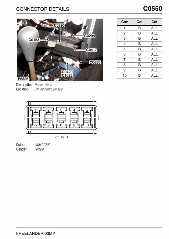
CONNECTOR DETAILS C0550
FREELANDER 03MY
C0550
Description: Header -EarthLocation: Behind centre console
Colour: LIGHT GREYGender: Female
P6826
C0550
C0420C1023
C0417
C0294
C0290
C0153
Cav Col Cct
1 B ALL2 B ALL3 B ALL
4 B ALL5 B ALL6 B ALL
7 B ALL8 B ALL9 B ALL
10 B ALL

C0551 CONNECTOR DETAILS
FREELANDER 03MY
C0551
Description: Header -EarthLocation: Rear of luggage compartment - RH side
Colour: LIGHT GREYGender: Female
C0473
C0122C0386
C0144C0385
C0117C0384
C0551
P7082
Cav Col Cct
1 B ALL2 B ALL3 B ALL
4 B ALL5 B ALL6 B ALL
7 B ALL8 B ALL9 B ALL
10 B ALL
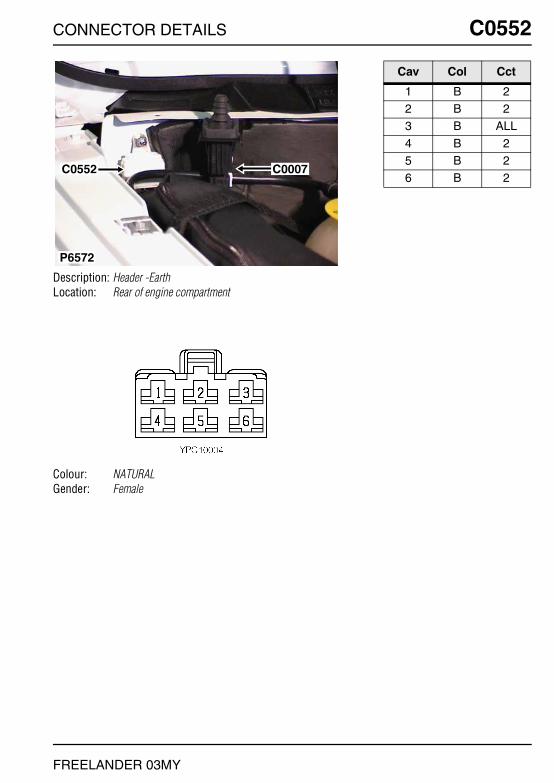
CONNECTOR DETAILS C0552
FREELANDER 03MY
C0552
Description: Header -EarthLocation: Rear of engine compartment
Colour: NATURALGender: Female
P6572
C0007C0552
Cav Col Cct
1 B 22 B 23 B ALL
4 B 25 B 26 B 2
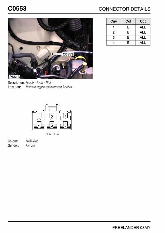
C0553 CONNECTOR DETAILS
FREELANDER 03MY
C0553
Description: Header -Earth - NASLocation: Beneath engine compartment fusebox
Colour: NATURALGender: Female
P6613
C0553
Cav Col Cct
1 B ALL2 B ALL3 B ALL
4 B ALL

CONNECTOR DETAILS C0556
FREELANDER 03MY
C0556
Description: EarthLocation: Rear of luggage compartment - LH side
Colour: TIN-PLATEGender: Eyelet
C0557C0556
P7094
Cav Col Cct
1 B ALL

C0557 CONNECTOR DETAILS
FREELANDER 03MY
C0557
Description: EarthLocation: Rear of luggage compartment - LH side
Colour: TIN-PLATEGender: Eyelet
C0557C0556
P7094
Cav Col Cct
1 B ALL

CONNECTOR DETAILS C0558
FREELANDER 03MY
C0558
Description: EarthLocation: Base of driver side 'A' post
Colour: TIN-PLATEGender: Eyelet
P7088
C0563C0562
C0565C0564
C1967C1964
C0559C0558
Cav Col Cct
1 B ALL

C0559 CONNECTOR DETAILS
FREELANDER 03MY
C0559
Description: EarthLocation: Base of driver side 'A' post
Colour: TIN-PLATEGender: Eyelet
P7088
C0563C0562
C0565C0564
C1967C1964
C0559C0558
Cav Col Cct
1 B 18

CONNECTOR DETAILS C0562
FREELANDER 03MY
C0562
Description: EarthLocation: Base of driver side 'A' post
Colour: TIN-PLATEGender: Eyelet
P7088
C0563C0562
C0565C0564
C1967C1964
C0559C0558
Cav Col Cct
1 B ALL

C0563 CONNECTOR DETAILS
FREELANDER 03MY
C0563
Description: EarthLocation: Base of driver side 'A' post
Colour: TIN-PLATEGender: Eyelet
P7088
C0563C0562
C0565C0564
C1967C1964
C0559C0558
Cav Col Cct
1 B 2
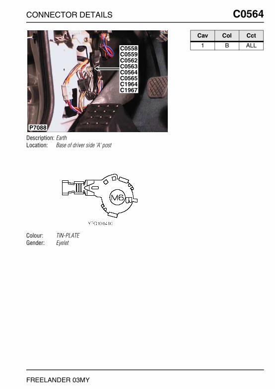
CONNECTOR DETAILS C0564
FREELANDER 03MY
C0564
Description: EarthLocation: Base of driver side 'A' post
Colour: TIN-PLATEGender: Eyelet
P7088
C0563C0562
C0565C0564
C1967C1964
C0559C0558
Cav Col Cct
1 B ALL

C0565 CONNECTOR DETAILS
FREELANDER 03MY
C0565
Description: EarthLocation: Base of driver side 'A' post
Colour: TIN-PLATEGender: Eyelet
P7088
C0563C0562
C0565C0564
C1967C1964
C0559C0558
Cav Col Cct
1 B ALL

CONNECTOR DETAILS C0567
FREELANDER 03MY
C0567
Description: Sensor-Inlet Air Temperature (IAT) and Manifold Absolute Pressure (MAP) - KV6
Location: Top of engine
Colour: BLACKGender: Female
P6607
C0567
C0177
C0175
C0152 Cav Col Cct
A BS ALLB KO ALLC YW ALL
D GW ALL

C0567 CONNECTOR DETAILS
FREELANDER 03MY
C0567
Description: Sensor-Inlet Air Temperature (IAT) and Manifold Absolute Pressure (MAP) - K1.8
Location: Top of engine
Colour: BLACKGender: Female
P6838
C0175
C0171C0521
C0176
C0164
C0567 Cav Col Cct
A KB ALLB YW ALLC YP ALL
D RG ALL

CONNECTOR DETAILS C0570
FREELANDER 03MY
C0570
Description: Fuse box-Engine compartmentLocation: Beneath engine compartment fusebox
Colour: BLACKGender: Female
P6635
C0577
C0576C0574 C0575
C0573
C0571C0570
C0572
Cav Col Cct
1 NK ALL2 N ALL3 NR ALL
4 GP ALL5 UN ALL6 PB ALL

C0571 CONNECTOR DETAILS
FREELANDER 03MY
C0571
Description: Fuse box-Engine compartmentLocation: Beneath engine compartment fusebox
Colour: BLACKGender: Female
P6635
C0577
C0576C0574 C0575
C0573
C0571C0570
C0572
Cav Col Cct
1 W ALL2 NR ALL3 N ALL

CONNECTOR DETAILS C0572
FREELANDER 03MY
C0572
Description: Fuse box-Engine compartmentLocation: Beneath engine compartment fusebox
Colour: NATURALGender: Female
P6635
C0577
C0576C0574 C0575
C0573
C0571C0570
C0572
Cav Col Cct
1 NR ALL2 NK 43 WP ALL

C0573 CONNECTOR DETAILS
FREELANDER 03MY
C0573
Description: Fuse box-Engine compartmentLocation: Beneath engine compartment fusebox
Colour: PURPLEGender: Female
P6635
C0577
C0576C0574 C0575
C0573
C0571C0570
C0572
Cav Col Cct
2 NG 343 SU 183 NG 34

CONNECTOR DETAILS C0574
FREELANDER 03MY
C0574
Description: Fuse box-Engine compartmentLocation: Beneath engine compartment fusebox
Colour: BLUEGender: Female
P6635
C0577
C0576C0574 C0575
C0573
C0571C0570
C0572
Cav Col Cct
1 NK ALL2 NW ALL3 G ALL

C0575 CONNECTOR DETAILS
FREELANDER 03MY
C0575
Description: Fuse box-Engine compartmentLocation: Beneath engine compartment fusebox
Colour: NATURALGender: Female
P6635
C0577
C0576C0574 C0575
C0573
C0571C0570
C0572
Cav Col Cct
1 G ALL2 GU ALL3 W 30
4 NK ALL5 R 286 NY 30
7 WN 308 NK 239 BP ALL
10 BR ALL12 RN ALL

CONNECTOR DETAILS C0576
FREELANDER 03MY
C0576
Description: Fuse box-Engine compartmentLocation: Beneath engine compartment fusebox
Colour: BLUEGender: Female
P6635
C0577
C0576C0574 C0575
C0573
C0571C0570
C0572
Cav Col Cct
1 RW ALL2 UG ALL3 GN ALL
4 PY ALL5 B 46 NG ALL
6 PN 177 B ALL8 PB ALL
9 WK ALL10 NK ALL10 RW 17
11 UB ALL12 NO ALL

C0577 CONNECTOR DETAILS
FREELANDER 03MY
C0577
Description: Fuse box-Engine compartmentLocation: Beneath engine compartment fusebox
Colour: WHITEGender: Female
P6635
C0577
C0576C0574 C0575
C0573
C0571C0570
C0572
Cav Col Cct
1 NW 17

CONNECTOR DETAILS C0578
FREELANDER 03MY
C0578
Description: Fuse box-Engine compartment - K1.8Location: Rear LH side of engine compartment
Colour: BLACKGender: Female
P6612
C0826C0578
Cav Col Cct
1 NK ALL2 NK ALL5 NU ALL
6 R ALL7 WN ALL8 NY ALL
10 W ALL11 NU ALL

C0578 CONNECTOR DETAILS
FREELANDER 03MY
C0578
Description: Fuse box-Engine compartment - KV6Location: Rear LH side of engine compartment
Colour: BLACKGender: Female
P6612
C0826C0578
Cav Col Cct
1 NK ALL2 NK ALL3 NP ALL
5 YU ALL7 WN ALL8 NY ALL
9 WK ALL10 W ALL11 YG ALL
12 BR ALL

CONNECTOR DETAILS C0578
FREELANDER 03MY
C0578
Description: Fuse box-Engine compartment - NASLocation: Rear LH side of engine compartment
Colour: BLACKGender: Female
C0578
C0826
P6792
Cav Col Cct
2 NK ALL5 YU ALL7 WN ALL
8 NY ALL9 NG ALL
10 W ALL
11 YG ALL

C0580 CONNECTOR DETAILS
FREELANDER 03MY
C0580
Description: Fuse box-Passenger compartmentLocation: Behind passenger compartment fusebox
Colour: LIGHT GREYGender: Female
P6550
C0582 C0584
C0585C0580
C0583
C0587
C0581
C0586
Cav Col Cct
1 LGW ALL2 LGK ALL3 W ALL
4 G ALL5 G ALL6 KO 25
7 P ALL8 NG ALL
10 LGN ALL
11 LGN ALL12 G ALL13 BW ALL
14 PW ALL15 GW ALL16 LG ALL
17 G ALL18 GR ALL
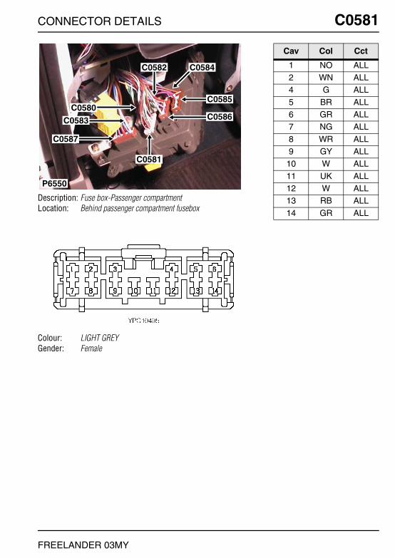
CONNECTOR DETAILS C0581
FREELANDER 03MY
C0581
Description: Fuse box-Passenger compartmentLocation: Behind passenger compartment fusebox
Colour: LIGHT GREYGender: Female
P6550
C0582 C0584
C0585C0580
C0583
C0587
C0581
C0586
Cav Col Cct
1 NO ALL2 WN ALL4 G ALL
5 BR ALL6 GR ALL7 NG ALL
8 WR ALL9 GY ALL
10 W ALL
11 UK ALL12 W ALL13 RB ALL
14 GR ALL

C0582 CONNECTOR DETAILS
FREELANDER 03MY
C0582
Description: Fuse box-Passenger compartmentLocation: Behind passenger compartment fusebox
Colour: LIGHT GREYGender: Female
P6550
C0582 C0584
C0585C0580
C0583
C0587
C0581
C0586
Cav Col Cct
1 RG 252 RO ALL3 GW ALL
4 GW ALL5 GR 256 UB ALL
9 W ALL10 LG ALL

CONNECTOR DETAILS C0583
FREELANDER 03MY
C0583
Description: Fuse box-Passenger compartmentLocation: Behind passenger compartment fusebox
Colour: NATURALGender: Female
P6550
C0582 C0584
C0585C0580
C0583
C0587
C0581
C0586
Cav Col Cct
1 RO ALL2 P ALL3 PN ALL
4 PR ALL6 GR ALL7 RB ALL
8 N ALL9 RY ALL
10 GW ALL

C0584 CONNECTOR DETAILS
FREELANDER 03MY
C0584
Description: Fuse box-Passenger compartmentLocation: Behind passenger compartment fusebox
Colour: BROWNGender: Female
P6550
C0582 C0584
C0585C0580
C0583
C0587
C0581
C0586
Cav Col Cct
1 N ALL2 PN ALL3 UG ALL

CONNECTOR DETAILS C0585
FREELANDER 03MY
C0585
Description: Fuse box-Passenger compartmentLocation: Behind passenger compartment fusebox
Colour: BROWNGender: Female
P6550
C0582 C0584
C0585C0580
C0583
C0587
C0581
C0586
Cav Col Cct
1 PR ALL2 WK 63 P ALL
4 SR ALL

C0586 CONNECTOR DETAILS
FREELANDER 03MY
C0586
Description: Fuse box-Passenger compartmentLocation: Behind passenger compartment fusebox
Colour: BROWNGender: Female
P6550
C0582 C0584
C0585C0580
C0583
C0587
C0581
C0586
Cav Col Cct
1 SO ALL3 G ALL4 RG ALL
5 WN 66 PN ALL

CONNECTOR DETAILS C0587
FREELANDER 03MY
C0587
Description: Fuse box-Passenger compartmentLocation: Behind passenger compartment fusebox
Colour: BROWNGender: Female
P6550
C0582 C0584
C0585C0580
C0583
C0587
C0581
C0586
Cav Col Cct
1 NW ALL2 B ALL3 N ALL
4 US ALL5 R ALL6 UO ALL
7 UW ALL

C0588 CONNECTOR DETAILS
FREELANDER 03MY
C0588
Description: Fuse box-Passenger compartmentLocation: Behind passenger compartment fusebox cover
Colour: BROWNGender: Female
P6650
C0589C0588Cav Col Cct
1 PS ALL2 NW ALL3 G ALL
4 WR ALL5 SU ALL

CONNECTOR DETAILS C0589
FREELANDER 03MY
C0589
Description: Fuse box-Passenger compartmentLocation: Behind passenger compartment fusebox cover
Colour: LIGHT GREYGender: Female
P6650
C0589C0588Cav Col Cct
1 UK ALL2 RG ALL3 RY ALL
5 WN ALL6 PB ALL7 GY ALL
8 RP ALL9 G ALL
10 BW ALL
11 GW ALL12 UY ALL13 GR ALL
14 UG ALL15 B ALL16 GP ALL
17 G ALL18 RB 3119 RB 15
19 RO 2020 P ALL

C0603 CONNECTOR DETAILS
FREELANDER 03MY
C0603
Description: Engine control module (ECM)Location: Inside E-box
Colour: BLACKGender: Female
P6808
C0603
C0331
C0332
C0604
C0606
Cav Col Cct
1 W 41 NK 173 K 17
4 B 265 B 266 B 26
7 NG 47 W 178 NK ALL
9 NK 49 WK 17

CONNECTOR DETAILS C0604
FREELANDER 03MY
C0604
Description: Engine control module (ECM)Location: Inside E-box
Colour: BLACKGender: Female
P7086
C0160C0450
C0646
C1258
C0603
C0604
C0606
C0331C0332
Cav Col Cct
9 PG 1710 BG 1717 GS 17

C0604 CONNECTOR DETAILS
FREELANDER 03MY
C0604
Description: Engine control module (ECM) - NASLocation: Inside E-box
Colour: BLACKGender: Female
P6808
C0603
C0331
C0332
C0604
C0606
Cav Col Cct
1 UY ALL7 GY ALL
13 GY ALL
14 UN ALL15 GN ALL16 UN ALL
18 GN ALL19 UY ALL20 BG ALL
21 BG ALL22 BG ALL23 NG ALL
24 BG ALL

CONNECTOR DETAILS C0606
FREELANDER 03MY
C0606
Description: Engine control module (ECM) - NASLocation: Inside E-box
Colour: BLACKGender: Female
P6808
C0603
C0331
C0332
C0604
C0606
Cav Col Cct
1 GW ALL5 UG ALL7 NW ALL
8 WU ALL10 NU ALL11 SB ALL
17 YW ALL18 BS ALL19 NP ALL
20 NG ALL21 BS ALL22 OG ALL
23 OS ALL24 KB ALL25 KG ALL
29 BO ALL30 BK ALL31 LGS ALL
32 BK ALL33 Y ALL34 YU ALL
35 YP ALL36 YN ALL37 YG ALL
38 YR ALL42 BO ALL43 NB ALL
44 GW ALL48 B ALL49 BG ALL
51 BG ALL

C0606 CONNECTOR DETAILS
FREELANDER 03MY
C0606
Description: Engine control module (ECM) - Td4Location: Inside E-box
Colour: BLACKGender: Female
P7086
C0160C0450
C0646
C1258
C0603
C0604
C0606
C0331C0332
Cav Col Cct
1 RY ALL2 Y ALL3 B ALL
4 Y ALL6 B ALL
10 NS ALL
12 BR ALL14 W ALL15 UY ALL
16 NG ALL17 N ALL19 SCR ALL
20 NG ALL23 NW ALL28 SU ALL
29 UW ALL31 Y ALL32 NG ALL
33 UB ALL35 WY ALL38 NU ALL
41 NG ALL50 U ALL

CONNECTOR DETAILS C0610
FREELANDER 03MY
C0610
Description: Roof harness to main harnessLocation: Behind driver side of fascia
Colour: LIGHT GREYGender: Male
P6554
C0084C0610
C0349C0421
C0341
Cav Col Cct
1 P ALL2 PW ALL3 B ALL
4 G 65 S 56 WB ALL
7 NB ALL8 SW ALL
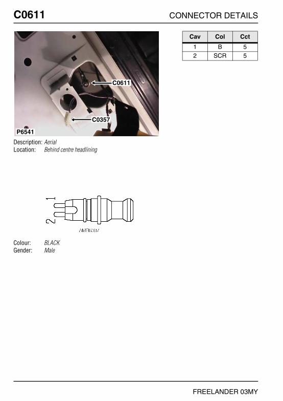
C0611 CONNECTOR DETAILS
FREELANDER 03MY
C0611
Description: AerialLocation: Behind centre headlining
Colour: BLACKGender: Male
P6541
C0611
C0357
Cav Col Cct
1 B 52 SCR 5

CONNECTOR DETAILS C0612
FREELANDER 03MY
C0612
Description: Motor-Window-Tail doorLocation: Centre of taildoor, behind trim panel
Colour: BLACKGender: Female
C0388
C0612
P6524
Cav Col Cct
1 KB 383 UG 384 SP 38
5 SR 386 UB 38

C0613 CONNECTOR DETAILS
FREELANDER 03MY
C0613
Description: Lamp-brake-high mountedLocation: Behind lamp
Colour: BLACKGender: Female
P6527
C0613Cav Col Cct
1 B ALL2 GP ALL

CONNECTOR DETAILS C0614
FREELANDER 03MY
C0614
Description: Motor-SunroofLocation: Front of headlining in the centre
Colour: LIGHT GREYGender: Female
C0619
C0355
C0614
P6589
Cav Col Cct
1 S 52 G 6

C0615 CONNECTOR DETAILS
FREELANDER 03MY
C0615
Description: Switch-Tail door openLocation: Behind number plate lamp
Colour: BLACKGender: Female
P6523
C0138 C139
C0615 Cav Col Cct
1 B ALL2 ON ALL3 US 38

CONNECTOR DETAILS C0616
FREELANDER 03MY
C0616
Description: Switch-Boot/tail doorLocation: LH side of taildoor
Colour: BLUEGender: Female
C0616
C0617
P6525
Cav Col Cct
1 B ALL2 BO ALL

C0617 CONNECTOR DETAILS
FREELANDER 03MY
C0617
Description: Motor-Lock-Tail doorLocation: LH side of taildoor
Colour: WHITEGender: Female
C0616
C0617
P6525
Cav Col Cct
1 PU ALL2 B ALL

CONNECTOR DETAILS C0618
FREELANDER 03MY
C0618
Description: Switch-Hill descent (1st gear)Location: Gearbox - Rear
Colour: BLACKGender: Female
C0618
P6604
Cav Col Cct
1 RW ALL2 B ALL

C0618 CONNECTOR DETAILS
FREELANDER 03MY
C0618
Description: Switch-Hill descent (1st gear) - K1.8Location: Gearbox - front
Colour: BLACKGender: Female
C0163 C0166
C0618C0169
P6617
Cav Col Cct
1 GB ALL2 B ALL

CONNECTOR DETAILS C0619
FREELANDER 03MY
C0619
Description: AerialLocation: Front of headlining in the centre
Colour: BLACKGender: Male
C0619
C0355
C0614
P6589
Cav Col Cct
1 B 62 SCR 6

C0639 CONNECTOR DETAILS
FREELANDER 03MY
C0639
Description: Speakers-Front - 3 DoorLocation: Behind front door trim panel
Colour: BLACKGender: Female
NO PHOTO LOCATION
Cav Col Cct
1 OB 92 OK 9

CONNECTOR DETAILS C0639
FREELANDER 03MY
C0639
Description: Speakers-Front - 5 DoorLocation: Behind front door trim panel
Colour: BLACKGender: Female
NO PHOTO LOCATION
Cav Col Cct
1 OB 92 OK 9
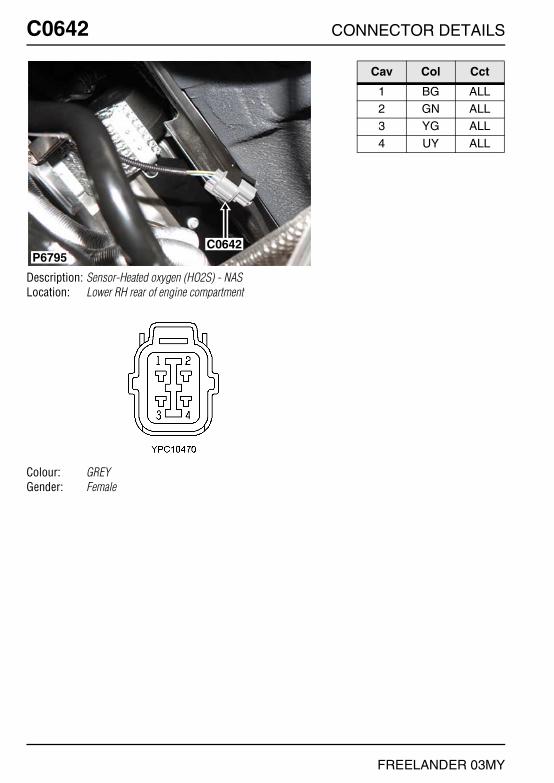
C0642 CONNECTOR DETAILS
FREELANDER 03MY
C0642
Description: Sensor-Heated oxygen (HO2S) - NASLocation: Lower RH rear of engine compartment
Colour: GREYGender: Female
C0642P6795
Cav Col Cct
1 BG ALL2 GN ALL3 YG ALL
4 UY ALL

CONNECTOR DETAILS C0643
FREELANDER 03MY
C0643
Description: Sensor-Heated oxygen (HO2S) - NASLocation: Centre rear of engine
Colour: GREYGender: Female
C0170
C0643
P6790
Cav Col Cct
1 BG ALL2 UN ALL3 YG ALL
4 GY ALL

C0644 CONNECTOR DETAILS
FREELANDER 03MY
C0644
Description: Sensor-Heated oxygen (HO2S) - NASLocation: Front of engine compartment - centre
Colour: ORANGEGender: Male
P6802
C0644
Cav Col Cct
1 BG ALL2 UN ALL3 YG ALL
4 UY ALL

CONNECTOR DETAILS C0645
FREELANDER 03MY
C0645
Description: Sensor-Heated oxygen (HO2S) - NASLocation: Centre rear of engine
Colour: ORANGEGender: Male
P6793
C0645
Cav Col Cct
1 BG ALL2 GN ALL3 YG ALL
4 GY ALL

C0646 CONNECTOR DETAILS
FREELANDER 03MY
C0646
Description: Fan-E-boxLocation: Inside E-box
Colour: NATURALGender: Female
P6809
C0646C0200C0451
C0932
C1258
Cav Col Cct
1 B ALL2 WR 162 NR 17
3 NK 28

CONNECTOR DETAILS C0652
FREELANDER 03MY
C0652
Description: Sensor-Brake pedalLocation: Driver's footwell
Colour: NATURALGender: Female
P6830
C0292 C0286
C0075
C0787
C0652
Cav Col Cct
1 W ALL2 B ALL3 GR ALL
4 PG ALL

C0667 CONNECTOR DETAILS
FREELANDER 03MY
C0667
Description: Switch-Clutch pedalLocation: Driver's footwell
Colour: NATURALGender: Female
P6555
C0667
Cav Col Cct
1 W 172 B 174 GR 17

CONNECTOR DETAILS C0675
FREELANDER 03MY
C0675
Description: Sensor-Gearbox positionLocation: Beneath centre console
Colour: BLACKGender: Female
C0675
C0878
P6822
Cav Col Cct
1 OB 232 GY 233 LGK 23
4 B 235 RO ALL7 RG 23
8 WB 239 RB 49 RO 23
9 RW 2510 WU 2311 NG 23
12 KO ALL

C0679 CONNECTOR DETAILS
FREELANDER 03MY
C0679
Description: Speakers-High RangeLocation: Behind rear door trim panel
Colour: WHITEGender: Female
C0679
P6812
Cav Col Cct
2 UB 93 UK 9

CONNECTOR DETAILS C0680
FREELANDER 03MY
C0680
Description: Speakers-High Range - 3 DoorLocation: Behind front door trim panel
Colour: LIGHT GREYGender: Female
P7093
C0680
Cav Col Cct
1 OB 92 OK 9
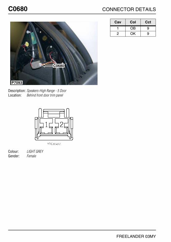
C0680 CONNECTOR DETAILS
FREELANDER 03MY
C0680
Description: Speakers-High Range - 5 DoorLocation: Behind front door trim panel
Colour: LIGHT GREYGender: Female
P7093
C0680
Cav Col Cct
1 OB 92 OK 9

CONNECTOR DETAILS C0714
FREELANDER 03MY
C0714
Description: Sensor-Air temperature-Fuel burning heaterLocation: Behind centre of bumper
Colour: BLACKGender: Female
P6543
C0714
Cav Col Cct
1 NY 172 SG 17

C0719 CONNECTOR DETAILS
FREELANDER 03MY
C0719
Description: Receiver-Radio frequency (RF)Location: Behind instrument pack
Colour:Gender:
P6839
C0359
C1000
C0230
C0719
C0233
Cav Col Cct
1 B ALL

CONNECTOR DETAILS C0723
FREELANDER 03MY
C0723
Description: HeaderLocation: Base of driver side 'A' post
Colour: BLUEGender: Female
P6553
C0723
C0398C0439
C0399C0440
Cav Col Cct
1 B 22 B 233 B ALL
4 B 25 B 26 B 2
7 B 28 B 2
13 B 2
14 B ALL15 B 1816 B ALL
17 B ALL18 B 2319 B 2
20 B 2

C0732 CONNECTOR DETAILS
FREELANDER 03MY
C0732
Description: Switch-Window-RearLocation: Behind rear door trim panel
Colour:Gender:
P6591
C0442
C0732
C0304
Cav Col Cct
1 SG 62 WR 63 R 6
4 U 65 WU 6

CONNECTOR DETAILS C0736
FREELANDER 03MY
C0736
Description: Mirror-Vanity-RHLocation: Headlining - front RH side
Colour: BLACKGender: Female
P6646
C0736
Cav Col Cct
1 P 402 B 40

C0737 CONNECTOR DETAILS
FREELANDER 03MY
C0737
Description: Mirror-Vanity-LHLocation: Headlining - front LH side
Colour: BLACKGender: Female
P6647
C0737
Cav Col Cct
1 P 402 B 40

CONNECTOR DETAILS C0749
FREELANDER 03MY
C0749
Description: Switch-Cruise controlLocation: Behind instrument pack surround LH side
Colour: WHITEGender: Female
C0749
P6818
Cav Col Cct
1 WK ALL2 RO ALL4 WY ALL
5 B ALL

C0750 CONNECTOR DETAILS
FREELANDER 03MY
C0750
Description: Switch-Fresh/recirculated airLocation: Behind centre console
Colour: WHITEGender: Female
C0131
C0275
C0750C0096C0072
P6815
Cav Col Cct
1 B ALL2 RO ALL3 Y ALL
4 K ALL5 LGS ALL

CONNECTOR DETAILS C0760
FREELANDER 03MY
C0760
Description: Mirror-Vanity-LH - JapanLocation: Headlining - front LH side
Colour: BLACKGender: Female
P7089
C0760
Cav Col Cct
1 P 402 B 40

C0787 CONNECTOR DETAILS
FREELANDER 03MY
C0787
Description: Sensor-Position-Accelerator pedal - NASLocation: Behind driver side of fascia
Colour: NATURALGender: Male
P6830
C0292 C0286
C0075
C0787
C0652
Cav Col Cct
1 RY ALL2 RN ALL4 RU ALL
5 YR ALL6 NR ALL8 UR ALL

CONNECTOR DETAILS C0803
FREELANDER 03MY
C0803
Description: Door harness to main harness - 5 DoorLocation: Base of 'B' post LH side
Colour: LIGHT GREYGender: Female
P6594
C0435C0803
Cav Col Cct
1 UB ALL2 UK ALL4 O ALL
5 B ALL6 K ALL7 PW ALL
8 NK ALL9 WR ALL
10 WU ALL
11 SG ALL12 RO ALL

C0809 CONNECTOR DETAILS
FREELANDER 03MY
C0809
Description: EarthLocation: Base of driver side 'A' post
Colour: TIN-PLATEGender: Eyelet
P7087
C0809C0808
C0439C0396
C0397C0440
C0811C1355
C1971C1412
Cav Col Cct
1 B 30

CONNECTOR DETAILS C0811
FREELANDER 03MY
C0811
Description: EarthLocation: Base of driver side 'A' post
Colour: TIN-PLATEGender: Eyelet
P7087
C0809C0808
C0439C0396
C0397C0440
C0811C1355
C1971C1412
Cav Col Cct
1 B ALL
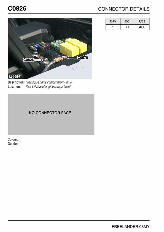
C0826 CONNECTOR DETAILS
FREELANDER 03MY
C0826
Description: Fuse box-Engine compartment - K1.8Location: Rear LH side of engine compartment
Colour:Gender:
P6612
C0826C0578
Cav Col Cct
1 R ALL

CONNECTOR DETAILS C0826
FREELANDER 03MY
C0826
Description: Fuse box-Engine compartment - KV6Location: Rear LH side of engine compartment
Colour:Gender:
P6612
C0826C0578
Cav Col Cct
1 R ALL

C0826 CONNECTOR DETAILS
FREELANDER 03MY
C0826
Description: Fuse box-Engine compartment - NASLocation: Rear LH side of engine compartment
Colour:Gender:
C0578
C0826
P6792
Cav Col Cct
1 R ALL
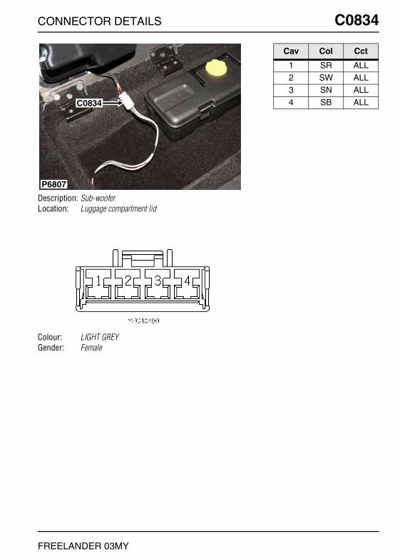
CONNECTOR DETAILS C0834
FREELANDER 03MY
C0834
Description: Sub-wooferLocation: Luggage compartment lid
Colour: LIGHT GREYGender: Female
C0834
P6807
Cav Col Cct
1 SR ALL2 SW ALL3 SN ALL
4 SB ALL

C0860 CONNECTOR DETAILS
FREELANDER 03MY
C0860
Description: Unit-Leak detection - NASLocation: Below RH rear wheelarch
Colour: BLACKGender: Female
P6832
C0860
Cav Col Cct
1 G 42 BG 43 U 4
4 NK 4
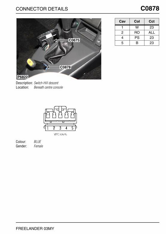
CONNECTOR DETAILS C0878
FREELANDER 03MY
C0878
Description: Switch-Hill descentLocation: Beneath centre console
Colour: BLUEGender: Female
C0675
C0878
P6822
Cav Col Cct
1 W 232 RO ALL4 PS 23
5 B 23

C0884 CONNECTOR DETAILS
FREELANDER 03MY
C0884
Description: Sensor-Ambient air temperatureLocation: Behind LH side of front bumper
Colour: BLACKGender: Female
C0884
P6797
Cav Col Cct
1 SO 42 B 4

CONNECTOR DETAILS C0895
FREELANDER 03MY
C0895
Description: Relay-Cruise controlLocation: Beneath driver's seat
Colour: BLACKGender: Female
P6835
C0895
Cav Col Cct
1 B ALL2 RG 263 RW ALL
4 PG 164 UW ALL5 BU 16
5 YN 266 GR 166 YB 26
7 WY ALL8 W 168 NK 26
9 PG 169 WU 26
11 B 16
12 WY 16

C0906 CONNECTOR DETAILS
FREELANDER 03MY
C0906
Description: Air conditioning (A/C) harness to heater harnessLocation: Behind centre console
Colour: YELLOWGender: Female
P7080
C0015C0431C0010
C0906
Cav Col Cct
1 B ALL3 LGS ALL4 RO ALL
5 SW ALL6 SK ALL

CONNECTOR DETAILS C0907
FREELANDER 03MY
C0907
Description: ECU-Mirror-FoldingLocation: Beneath centre console
Colour:Gender:
P6583
C0907
Cav Col Cct
1 O ALL2 UB ALL3 Y ALL
4 NS ALL5 B ALL

C0908 CONNECTOR DETAILS
FREELANDER 03MY
C0908
Description: Sensor-Heated oxygen (HO2S)Location: Beneath centre console
Colour: BLACKGender: Female
P6656
C0908
C0410
C0268
Cav Col Cct
1 OY 161 KB 182 BG 16
2 LGS 183 UW 163 GU 18
4 NK 30

CONNECTOR DETAILS C0913
FREELANDER 03MY
C0913
Description: Engine harness to main harnessLocation: Inside E-box
Colour: BLACKGender: Female
P6618
C0914
C0162C0448
C0913
Cav Col Cct
53 UB 1854 WK 1857 UO 32
58 K 1859 B 1861 W 18
65 YB 1866 B 1867 UR 18
67 UW 3268 BP 1870 UG 32
71 PB 3272 YR 1873 B 18
77 UY 1879 YN 1880 NG 18

C0914 CONNECTOR DETAILS
FREELANDER 03MY
C0914
Description: Engine harness to main harnessLocation: Inside E-box
Colour: BLACKGender: Female
P6618
C0914
C0162C0448
C0913
Cav Col Cct
1 BU ALL3 KB ALL4 NB ALL
6 KB ALL7 KB ALL8 YP ALL
13 OS ALL14 YR ALL15 KB ALL
16 YP ALL19 NK ALL20 GY ALL
24 OU ALL25 YU ALL26 WB ALL
27 GU ALL29 LGS ALL30 B ALL
31 KB ALL32 GO ALL33 KG ALL
34 KB ALL35 WR ALL37 GO ALL
38 BO ALL39 OG ALL40 YN ALL
41 LGS ALL42 BS ALL44 YW ALL
45 RG ALL46 KP ALL47 BO ALL
50 KU ALL51 YG ALL52 WO ALL

CONNECTOR DETAILS C0916
FREELANDER 03MY
C0916
Description: Lamp-Side marker-Front-RHLocation: Behind RH side of front bumper
Colour: BLACKGender: Female
P6798
C0916
Cav Col Cct
1 RO 42 B 4
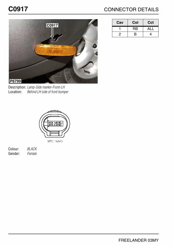
C0917 CONNECTOR DETAILS
FREELANDER 03MY
C0917
Description: Lamp-Side marker-Front-LHLocation: Behind LH side of front bumper
Colour: BLACKGender: Female
C0917
P6799
Cav Col Cct
1 RB ALL2 B 4

CONNECTOR DETAILS C0918
FREELANDER 03MY
C0918
Description: Lamp-Side marker-Rear-RHLocation: Behind RH side of rear bumper
Colour: BLACKGender: Female
P6796
C0918
Cav Col Cct
1 RO 42 B 4
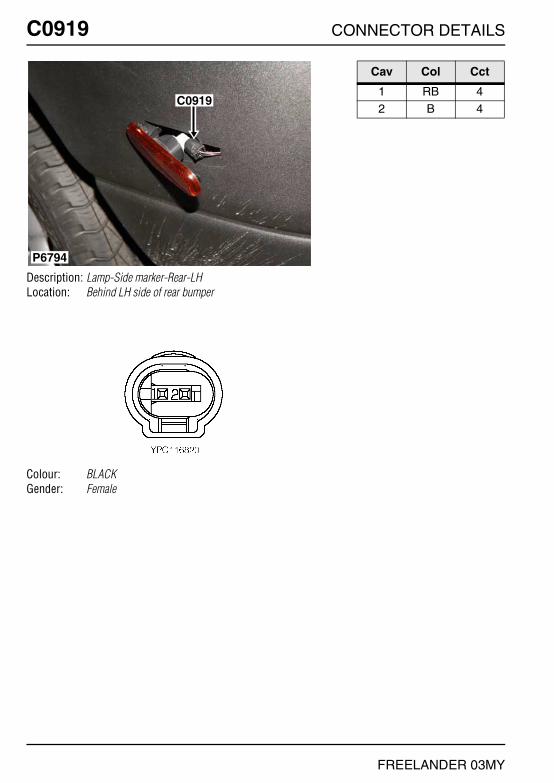
C0919 CONNECTOR DETAILS
FREELANDER 03MY
C0919
Description: Lamp-Side marker-Rear-LHLocation: Behind LH side of rear bumper
Colour: BLACKGender: Female
P6794
C0919
Cav Col Cct
1 RB 42 B 4

CONNECTOR DETAILS C0921
FREELANDER 03MY
C0921
Description: Head Unit-Audio SystemLocation: Behind centre console
Colour: GREYGender: Female
C0092
C0921
P6816
Cav Col Cct
1 WO 122 BW ALL2 GN 12
3 BR ALL4 P 94 PK ALL
5 PY ALL6 RO ALL7 LGW ALL
8 B ALL

C0922 CONNECTOR DETAILS
FREELANDER 03MY
C0922
Description: Head Unit-Audio SystemLocation: Behind centre console
Colour: GREENGender: Female
NO PHOTO LOCATION
Cav Col Cct
12 K ALL

CONNECTOR DETAILS C0925
FREELANDER 03MY
C0925
Description: Heater-Fuel burningLocation: Behind LH side of front bumper
Colour: BLACKGender: Female
P6544
C0926
C0925
Cav Col Cct
2 K 173 SG 176 WU 17
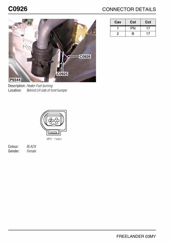
C0926 CONNECTOR DETAILS
FREELANDER 03MY
C0926
Description: Heater-Fuel burningLocation: Behind LH side of front bumper
Colour: BLACKGender: Female
P6544
C0926
C0925
Cav Col Cct
1 PN 172 B 17

CONNECTOR DETAILS C0932
FREELANDER 03MY
C0932
Description: ECU-Electronic automatic transmissionLocation: Inside E-box
Colour: BLACKGender: Female
P6809
C0646C0200C0451
C0932
C1258
Cav Col Cct
1 K 233 GP 234 GR 23
5 U 237 OB 238 GY 23
9 B 2310 OG 2312 YN ALL
13 YN 2314 O 2315 R 23
16 U 2317 SB 2318 Y 23
19 GB 2320 KB 2321 R 23
24 R 2325 WU 2326 NG 23
27 WB 2330 KO ALL33 YB ALL
34 YB 2336 NK 2337 GK 23
38 B 2339 WK 2341 LGK 23
43 GR 2345 RG 2349 WU ALL
50 GW 2352 OU 2353 K 23
54 NK 23

C0935 CONNECTOR DETAILS
FREELANDER 03MY
C0935
Description: Relay-ReverseLocation: Behind driver side of fascia
Colour: BLACKGender: Female
P6843
C0935
C0936
Cav Col Cct
2 G 234 B 236 NG 23
8 GN 23
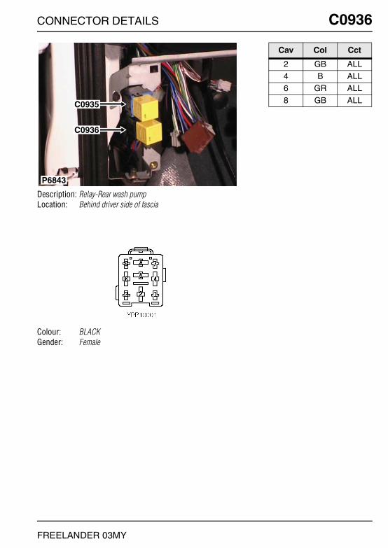
CONNECTOR DETAILS C0936
FREELANDER 03MY
C0936
Description: Relay-Rear wash pumpLocation: Behind driver side of fascia
Colour: BLACKGender: Female
P6843
C0935
C0936
Cav Col Cct
2 GB ALL4 B ALL6 GR ALL
8 GB ALL

C0941 CONNECTOR DETAILS
FREELANDER 03MY
C0941
Description: CD auto changerLocation: Beneath driver's seat
Colour:Gender:
NO PHOTO LOCATION
Cav Col Cct
1 YB ALL2 BY ALL3 B ALL
5 K 135 WRY 146 KB ALL
7 BK ALL8 B ALL
10 PK 13
10 P 14

CONNECTOR DETAILS C0972
FREELANDER 03MY
C0972
Description: Valve-Balance-1 - KV6Location: Top of engine
Colour: BLACKGender: Female
P6610
C0973
C0972
Cav Col Cct
1 SB ALL2 OU ALL3 B ALL
4 YU ALL

C0972 CONNECTOR DETAILS
FREELANDER 03MY
C0972
Description: Valve-Balance-1 - NASLocation: Top of engine
Colour: BLACKGender: Female
P6610
C0973
C0972
Cav Col Cct
1 SB ALL2 OU ALL3 B ALL
4 YU ALL

CONNECTOR DETAILS C0973
FREELANDER 03MY
C0973
Description: Valve-Butterfly - KV6Location: Top of engine
Colour: BLACKGender: Female
P6610
C0973
C0972
Cav Col Cct
1 OY ALL2 B ALL3 YU ALL
4 UK ALL

C0973 CONNECTOR DETAILS
FREELANDER 03MY
C0973
Description: Valve-Butterfly - NASLocation: Top of engine
Colour: BLACKGender: Female
P6610
C0973
C0972
Cav Col Cct
1 BG ALL2 B ALL3 YU ALL
4 UK ALL
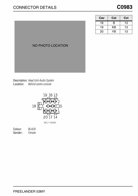
CONNECTOR DETAILS C0983
FREELANDER 03MY
C0983
Description: Head Unit-Audio SystemLocation: Behind centre console
Colour: BLACKGender: Female
NO PHOTO LOCATION
Cav Col Cct
18 B 1319 KB 1320 YB 13

C0994 CONNECTOR DETAILS
FREELANDER 03MY
C0994
Description: Relay-Heated front screenLocation: Rear LH side of engine compartment
Colour:Gender:
P6811
C0192
C0994
C1860
Cav Col Cct
1 N ALL2 N ALL3 SB ALL
4 NW ALL

CONNECTOR DETAILS C1000
FREELANDER 03MY
C1000
Description: HeaderLocation: Behind instrument pack
Colour: GREENGender: Female
P6839
C0359
C1000
C0230
C0719
C0233
Cav Col Cct
1 P ALL2 P ALL3 P ALL
4 P ALL5 RB 156 RB 15
7 RB 159 RO ALL
10 RO ALL
11 RO ALL12 RO ALL13 B ALL
14 B ALL15 B ALL16 B 31
17 B ALL18 B ALL19 B ALL
20 B ALL

C1023 CONNECTOR DETAILS
FREELANDER 03MY
C1023
Description: Main harness to audio system harnessLocation: Behind centre console
Colour: LIGHT GREYGender: Female
P6826
C0550
C0420C1023
C0417
C0294
C0290
C0153
Cav Col Cct
1 YK ALL2 OK ALL3 SK ALL
4 LGW ALL5 UK ALL6 YB ALL
7 P ALL8 BW ALL9 OB ALL
10 SB ALL11 RO ALL12 UB ALL
13 B ALL14 BR ALL15 WO ALL
16 GN ALL17 SB ALL18 SN ALL
19 SW ALL20 SR ALL
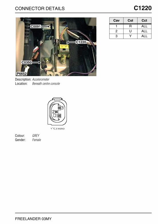
CONNECTOR DETAILS C1220
FREELANDER 03MY
C1220
Description: AccelerometerLocation: Beneath centre console
Colour: GREYGender: Female
P6652
C0091
C0350
C1220
Cav Col Cct
1 R ALL2 U ALL3 Y ALL

C1257 CONNECTOR DETAILS
FREELANDER 03MY
C1257
Description: Sensor-Pressure-Air ConditioningLocation: Lower RH front of engine compartment
Colour: BLACKGender: Female
P6546
C0127
C1257
Cav Col Cct
1 PB ALL2 UG ALL3 UO ALL

CONNECTOR DETAILS C1258
FREELANDER 03MY
C1258
Description: Sensor-Temperature-E-boxLocation: Inside E-box
Colour: BLACKGender: Female
P6809
C0646C0200C0451
C0932
C1258
Cav Col Cct
1 NK 282 NK 28

C1354 CONNECTOR DETAILS
FREELANDER 03MY
C1354
Description: Head Unit-Audio SystemLocation: Behind centre console
Colour: BLACKGender: Female
C0098C1354
P6814
Cav Col Cct
1 KB 142 YB 143 B 14
6 BK 147 BY 14
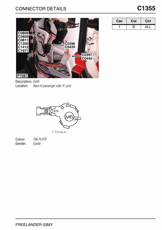
CONNECTOR DETAILS C1355
FREELANDER 03MY
C1355
Description: EarthLocation: Base of passenger side 'A' post
Colour: TIN-PLATEGender: Eyelet
P7087
C0809C0808
C0439C0396
C0397C0440
C0811C1355
C1971C1412
Cav Col Cct
1 B ALL
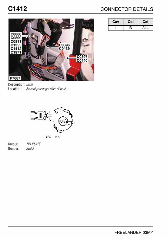
C1412 CONNECTOR DETAILS
FREELANDER 03MY
C1412
Description: EarthLocation: Base of passenger side 'A' post
Colour: TIN-PLATEGender: Eyelet
P7087
C0809C0808
C0439C0396
C0397C0440
C0811C1355
C1971C1412
Cav Col Cct
1 B ALL

CONNECTOR DETAILS C1577
FREELANDER 03MY
C1577
Description: SpeakersLocation: Behind rear door trim panel
Colour: BLACKGender: Female
C1577
P6823
Cav Col Cct
1 UB 92 UK 9

C1610 CONNECTOR DETAILS
FREELANDER 03MY
C1610
Description: Sensor-Pressure-Fuel railLocation: Top of engine
Colour: BLACKGender: Female
P6600
C1610
Cav Col Cct
1 NG ALL2 UB ALL3 WY ALL
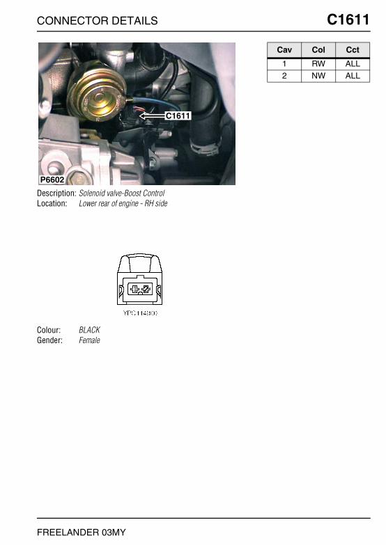
CONNECTOR DETAILS C1611
FREELANDER 03MY
C1611
Description: Solenoid valve-Boost ControlLocation: Lower rear of engine - RH side
Colour: BLACKGender: Female
P6602
C1611
Cav Col Cct
1 RW ALL2 NW ALL

C1667 CONNECTOR DETAILS
FREELANDER 03MY
C1667
Description: Regulator-Fuel pressureLocation: Front of engine - centre
Colour:Gender:
P6627
C1667
C0187
Cav Col Cct
1 RW ALL2 NU ALL

CONNECTOR DETAILS C1680
FREELANDER 03MY
C1680
Description: Control Unit-Cooling FanLocation: Front of engine compartment - centre
Colour:Gender:
P6824
C0208
C1680
Cav Col Cct
1 UW ALL2 NK ALL

C1704 CONNECTOR DETAILS
FREELANDER 03MY
C1704
Description: Main harness to heated front screen harnessLocation: Rear LH side of engine compartment
Colour: GREYGender: Female
C0420C1704
P6810
Cav Col Cct
1 SB 282 PK 28

CONNECTOR DETAILS C1770
FREELANDER 03MY
C1770
Description: Ignition coil-4 - KV6Location: Top of engine
Colour: BLACKGender: Female
P6574
C0052
C1770
C1772
Cav Col Cct
1 BY ALL2 B ALL3 NK ALL
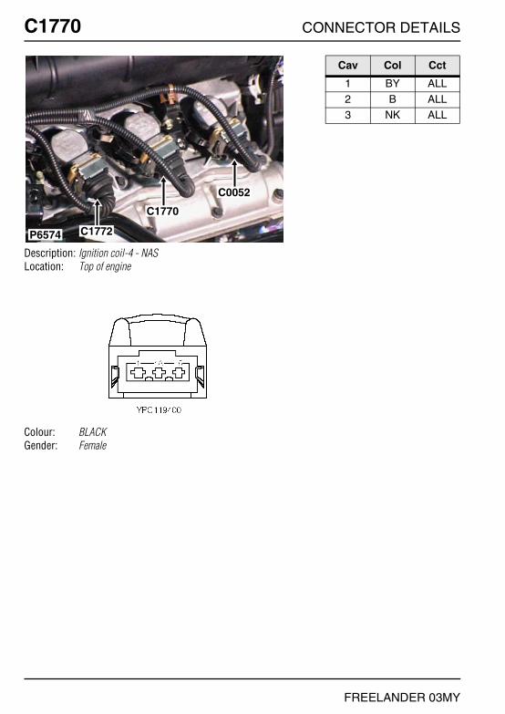
C1770 CONNECTOR DETAILS
FREELANDER 03MY
C1770
Description: Ignition coil-4 - NASLocation: Top of engine
Colour: BLACKGender: Female
P6574
C0052
C1770
C1772
Cav Col Cct
1 BY ALL2 B ALL3 NK ALL

CONNECTOR DETAILS C1771
FREELANDER 03MY
C1771
Description: Ignition coil-5 - KV6Location: Top of engine
Colour: BLACKGender: Female
P7083
C1771C0276
C0526
C0524
C0522
C0156
Cav Col Cct
1 BP ALL2 B ALL3 NK ALL

C1771 CONNECTOR DETAILS
FREELANDER 03MY
C1771
Description: Ignition coil-5 - NASLocation: Top of engine
Colour: BLACKGender: Female
P6800
C0038 C0276
C0556C0156
C1771
Cav Col Cct
1 BP ALL2 B ALL3 NK ALL

CONNECTOR DETAILS C1772
FREELANDER 03MY
C1772
Description: Ignition coil-6 - KV6Location: Top of engine
Colour: BLACKGender: Female
P6574
C0052
C1770
C1772
Cav Col Cct
1 BU ALL2 B ALL3 NK ALL

C1772 CONNECTOR DETAILS
FREELANDER 03MY
C1772
Description: Ignition coil-6 - NASLocation: Top of engine
Colour: BLACKGender: Female
P6574
C0052
C1770
C1772
Cav Col Cct
1 BU ALL2 B ALL3 NK ALL

CONNECTOR DETAILS C1860
FREELANDER 03MY
C1860
Description: Holder-FuseLocation: Rear LH side of engine compartment
Colour:Gender:
P6811
C0192
C0994
C1860
Cav Col Cct
1A NW ALL1B PS ALL2A NW ALL
2B PW ALL3A NW ALL3B PG ALL

C1875 CONNECTOR DETAILS
FREELANDER 03MY
C1875
Description: Holder-FuseLocation: Beneath engine compartment fusebox
Colour: BLACKGender: Female
P7093
C0420C0483
C0157
C1875
Cav Col Cct
1 RW 251 R ALL2 RO 25
2 N ALL

CONNECTOR DETAILS C1876
FREELANDER 03MY
C1876
Description: Holder-FuseLocation: LH side of engine compartment
Colour:Gender:
C0192
C1876
C0154
P7091
Cav Col Cct
1A B ALL1B BP ALL2A B ALL
2B BN ALL3A B ALL3B BG ALL

C1877 CONNECTOR DETAILS
FREELANDER 03MY
C1877
Description: Heater-PTCLocation: Behind centre of fascia
Colour: BROWNGender: Female
C1879
C1878
C1877
P7097
Cav Col Cct
2 BN ALL

CONNECTOR DETAILS C1878
FREELANDER 03MY
C1878
Description: Heater-PTCLocation: Behind centre of fascia
Colour: BROWNGender: Female
C1879
C1878
C1877
P7097
Cav Col Cct
1 BG ALL

C1879 CONNECTOR DETAILS
FREELANDER 03MY
C1879
Description: Heater-PTCLocation: Behind centre of fascia
Colour: BROWNGender: Female
C1879
C1878
C1877
P7097
Cav Col Cct
3 BP ALL

CONNECTOR DETAILS C1897
FREELANDER 03MY
C1897
Description: Module-ICE interfaceLocation: Behind centre console
Colour: BLACKGender: Female
NO PHOTO LOCATION
Cav Col Cct
1 LGW 122 BR 123 K ALL
5 BW 126 B ALL

C1959 CONNECTOR DETAILS
FREELANDER 03MY
C1959
Description: Interface-Cruise controlLocation: Beneath RH seat
Colour: BLACKGender: Female
P6651
C0239
C1959
Cav Col Cct
1 B ALL2 RG 263 RW 26
4 PG 164 UW 265 BU 16
5 YN 266 GR 166 YB 26
7 WY 268 NK 269 PG 16
9 WU 2611 B 1612 WY 16

CONNECTOR DETAILS C1967
FREELANDER 03MY
C1967
Description: EarthLocation: Base of driver side 'A' post
Colour: TIN-PLATEGender: Eyelet
P7088
C0563C0562
C0565C0564
C1967C1964
C0559C0558
Cav Col Cct
1 B ALL

C1968 CONNECTOR DETAILS
FREELANDER 03MY
C1968
Description: EarthLocation: Base of driver side 'A' post
Colour: TIN-PLATEGender: Eyelet
P6552
C0563C0562
C0565C0564
C1947C1413
C1967C1968
C1964
C0559C0558
C0561C0560
Cav Col Cct
1 B ALL

CONNECTOR DETAILS C1971
FREELANDER 03MY
C1971
Description: EarthLocation: Base of passenger side 'A' post
Colour: TIN-PLATEGender: Eyelet
P7087
C0809C0808
C0439C0396
C0397C0440
C0811C1355
C1971C1412
Cav Col Cct
1 B 3

C1972 CONNECTOR DETAILS
FREELANDER 03MY
C1972
Description: EarthLocation: Top of engine
Colour: TIN-PLATEGender: Eyelet
P6573
C1972
C0521C0171
Cav Col Cct
1 B 34

CONNECTOR DETAILS C1976
FREELANDER 03MY
C1976
Description: Relay-IlluminationLocation: Behind RH side of fascia
Colour: BLACKGender: Female
C1976
P6827
Cav Col Cct
2 NR 234 P 235 NK 23
6 BR 238 P 23

C1977 CONNECTOR DETAILS
FREELANDER 03MY
C1977
Description: Vacuum enhanceLocation: Rear of engine compartment
Colour: BLACKGender: Female
P6803
C1977
C0152
Cav Col Cct
1 BS ALL2 YU ALL
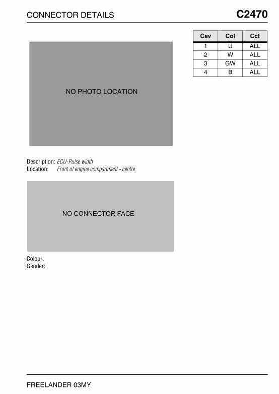
CONNECTOR DETAILS C2470
FREELANDER 03MY
C2470
Description: ECU-Pulse widthLocation: Front of engine compartment - centre
Colour:Gender:
NO PHOTO LOCATION
Cav Col Cct
1 U ALL2 W ALL3 GW ALL
4 B ALL

C2575 CONNECTOR DETAILS
FREELANDER 03MY
C2575
Description: Micro switchLocation: Behind centre console
Colour:Gender:
C0422
C2575
P7096
Cav Col Cct
1 SK ALL2 B ALL3 B ALL