free your innovation - the world's leading software … · free your innovation ... making it...
TRANSCRIPT

Free your innovation
Freenove is an open-source electronics platform.
www.freenove.com

About
Freenove is an open-source electronics platform. Freenove is committed to helping customer quickly realize
the creative idea and product prototypes, making it easy to get started for enthusiasts of programing and
electronics and launching innovative open source products. Our services include:
Electronic components and modules
Learning kits for Arduino
Learning kits for Raspberry Pi
Learning kits for Technology
Robot kits
Auxiliary tools for creations
Our code and circuit are open source. You can obtain the details and the latest information through visiting
the following web sites:
http://www.freenove.com
https://github.com/freenove
Your comments and suggestions are warmly welcomed, please send them to the following email address:
Support
Freenove provides free and quick technical support, including but not limited to:
Quality problems of products
Problems in using products
Questions for learning and technology
Opinions and suggestions
Ideas and thoughts
Please send email to:
On working day, we usually reply to you within 24 hours.
Copyright
Freenove reserves all rights to this book. No copies or plagiarizations are allowed for the purpose of
commercial use.
The code and circuit involved in this product are released as Creative Commons Attribution ShareAlike 3.0.
This means you can use them on your own derived works, in part or completely, as long as you also adopt
the same license. Freenove brand and Freenove logo are copyright of Freenove Creative Technology Co., Ltd
and cannot be used without formal permission.

I Preface
█ www.freenove.com
Contents
Contents .................................................................................... I
Preface ...................................................................................... 1
Install Processing Software ............................................................................................................................................................. 1
First Use .................................................................................................................................................................................................. 3
Chapter 1 LED ........................................................................ 5
Project 1.1 Blink ................................................................................................................................................................................... 5
Project 1.2 MouseLED .................................................................................................................................................................... 11
Chapter 2 LEDBar Graph ................................................. 13
Project 2.1 FollowLight ................................................................................................................................................................... 13
Chapter 3 PWM .................................................................. 17
Project 3.1 BreathingLED............................................................................................................................................................... 17
Chapter 4 RGBLED ............................................................. 23
Project 4.1 ColorfulLED .................................................................................................................................................................. 23
Chapter 5 Buzzer ............................................................... 30
Project 5.1 ActiveBuzzer ................................................................................................................................................................ 30
Chapter 6 PCF8591 ........................................................... 34
Project 6.1 ADC & DAC ................................................................................................................................................................. 34
Chapter 7 ADC & LED ...................................................... 39
Project 7.1 SoftLight ........................................................................................................................................................................ 39
Project 7.2 NightLamp ................................................................................................................................................................... 43
Chapter 8 Thermistor ....................................................... 45
Project 8.1 Thermometer .............................................................................................................................................................. 45
Chapter 9 Motor & Driver .............................................. 49
Project 9.1 Motor.............................................................................................................................................................................. 49
Chapter 10 74HC595 & LEDBar Graph ...................... 58
Project 10.1 FollowLight ................................................................................................................................................................ 58
Chapter 11 74HC595 & Seven-segment display. .. 64
Project 11.1 Seven -segment display. ..................................................................................................................................... 64

II Preface www.freenove.com █
Project 11.2 4-digit Seven-segment display. ....................................................................................................................... 70
Chapter 12 74HC595 & LED Matrix ............................ 78
Project 12.1 LED Matrix.................................................................................................................................................................. 78
Chapter 13 I2C-LCD1602 ............................................... 87
Project 13.1 LCD ............................................................................................................................................................................... 87
Chapter 14 Joystick ........................................................... 93
Project 14 Joystick ............................................................................................................................................................................ 93
Chapter 15 Relay & Motor ............................................. 98
Project 15.1 Relay & Motor .......................................................................................................................................................... 98
Chapter 16 Stepping Motor......................................... 106
Project 16.1 Stepping Motor .................................................................................................................................................... 106
Chapter 17 Matrix Keypad............................................ 115
Project 17.1 Calculator ................................................................................................................................................................ 115
Chapter 18 Infrared Motion Sensor .......................... 123
Project 18.1 Sense LED................................................................................................................................................................ 123
App 1 Oscilloscope ......................................................... 127
App 1.1 Oscilloscope ................................................................................................................................................................... 127
App 2 Control Graphics ................................................. 130
App 2.1 Ellipse ................................................................................................................................................................................ 130
App 3 Pong Game ........................................................... 133
App 3.1 Pong Game ..................................................................................................................................................................... 133
App 4 Snake Game ......................................................... 138
App 4.1 Snake Game ................................................................................................................................................................... 138
App 5 Tetris Game .......................................................... 143
App 5.1 Tetris Game .................................................................................................................................................................... 143
What's next? ...................................................................... 148

1 Preface
█ www.freenove.com
Preface
Processing software is used to write programs that can run on computers. Processing software is free and
open source, and runs on the Mac, Windows, and GNU/Linux platforms, which is the same with Arduino
software. In fact, the development of Arduino software is based on Processing software, and they still have
similar interface.
Programs written using Processing are also called sketches,and Java is the default language. Java language
and C++ language has many similarities, so the readers who have learned our basic tutorial are able to
understand and write simple Processing sketches quickly.
Processing continues to be an alternative to proprietary software tools with restrictive and expensive licenses,
making it accessible to schools and individual students. Its open source status encourages the community
participation and collaboration that is vital to Processing's growth. Contributors share programs, contribute
code, and build libraries, tools, and modes to extend the possibilities of the software. The Processing
community has written more than a hundred libraries to facilitate computer vision, data visualization, music
composition, networking, 3D file exporting, and programming electronics.
This tutorial is applicable for Freenove Ultimate Starter Kit for Raspberry Pi. If you have learned our C and
python tutorials, or you have learned basic electronic circuits and programming, you can start learning this
tutorial. Otherwise, we recommend that you had better learn our C and Python tutorials first. Sketchs of this
tutorial is written by java language in processing software. This tutorial has similar projects to C and python
tutorials. And graphical man-machine interface is added to achieve perfect integration of electronic circuits,
computer software, images and so on, which will let the readers fully experience the fun of programming and
DIY.
This tutorial will introduce how to install and use processing software on Raspberry Pi through some electronic
circuit projects. Chapters and sequence is similar to C and python tutorial. Equally, detailed description and
explanation is arranged for the skect in each project. Our elaborate electronic circuits and interactive project
with Processing are attached in the end, including virtual instruments, games (2D and 3D versions), etc.
Install Processing Software
Processing software / Processing Development Environment (PDE) makes it easy to write Processing programs.
First install Processing software: type following command in the terminal to start installation:
curl https://processing.org/download/install-arm.sh | sudo sh
Ensures that your RPi always has the Internet to access in the installation process.

2 Preface www.freenove.com █
You can also download and install the software by visiting the official website https://processing.org/.
After the installation is completed, you can enter the "processing" to open processing software in any directory
of the terminal, or open the software processing in the start menu of the system, as shown below:
Interface of processing software is shown below:
You're now running the Processing Development Environment (or PDE). There's not much to it; the large area
is the Text Editor, and there's a row of buttons across the top; this is the toolbar. Below the editor is the
Message Area, and below that is the Console. The Message Area is used for one line messages, and the
Console is used for more technical details.
Menu
ToolBar
Tabs
Text
Editor
Message Area
Console
Welcome Page
3 Preface
█ www.freenove.com
First Use
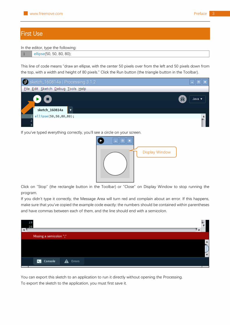
In the editor, type the following:
1 ellipse(50, 50, 80, 80);
This line of code means "draw an ellipse, with the center 50 pixels over from the left and 50 pixels down from
the top, with a width and height of 80 pixels." Click the Run button (the triangle button in the Toolbar).
If you've typed everything correctly, you'll see a circle on your screen.
Click on "Stop" (the rectangle button in the Toolbar) or "Close" on Display Window to stop running the
program.
If you didn't type it correctly, the Message Area will turn red and complain about an error. If this happens,
make sure that you've copied the example code exactly: the numbers should be contained within parentheses
and have commas between each of them, and the line should end with a semicolon.
You can export this sketch to an application to run it directly without opening the Processing.
To export the sketch to the application, you must first save it.
Display Window

4 Preface www.freenove.com █
So far, we have completed the first use. I believe you have felt the joy of it.

5 Chapter 1 LED
█ www.freenove.com
Chapter 1 LED
We will still start from Blink LED in this chapter, and also learn the usage of some commonly used functions
of Processing Software.
Project 1.1 Blink
In this project, we will make a Blink LED and let Display window of Processing Blink at the same time.

6 Chapter 1 LED www.freenove.com █
Component List
Raspberry Pi 3B x1
GPIO Extension Board & Wire x1
BreadBoard x1
LED x1
Resistor 220Ω x1
Jumper Wire M/M x2
In the components list, 3B GPIO, Extension Shield Raspberry and Breadboard are necessary for each
experiment. They will be listed only in text form.

7 Chapter 1 LED
█ www.freenove.com
Circuit
Disconnect RPi from GPIO Extension Shield first. Then build the circuit according to the circuit diagram and
the hardware connection diagram. After the circuit is built and confirmed, connect RPi to GPIO Extension
Shield. In addition, short circuit (especially 5V and GND, 3.3V and GND) should be avoid, because short circuit
may cause anormal circuit work, or even damage to PRi.
Schematic diagram
Hardware connection
Because Numbering of GPIO Extension Shield is the same as RPi GPIO, latter Hardware connection diagram
will only show the part of breadboard and GPIO Extension Shield.

8 Chapter 1 LED www.freenove.com █
Sketch
Sketch 1.1.1 Blink
First observe the running result of the sketch, and then analyze the code.
1. Use Processing to open the file Sketch_01_1_1_Blink.
processing
Freenove_Ultimate_Starter_Kit_for_Raspberry_Pi/Processing/Sketchs/Sketch_01_1_1_Blink/Sketch_01_1_1_Blin
k.pde
2. Click on "RUN" to run the code.
After the program is executed, LED will start Blinking and background of Display window will change with the
change of LED state.
The following is program code:
1
2
3
4
5
6
7
8
9
10
11
12
13
14
15
16
17
18
19
20
21
import processing.io.*;
int ledPin = 17; //define ledPin
boolean ledState = false; //define ledState
void setup() {
size(100, 100);
frameRate(1); //set frame rate
GPIO.pinMode(ledPin, GPIO.OUTPUT); //set the ledPin to output mode
}
void draw() {
ledState = !ledState;
if (ledState) {
GPIO.digitalWrite(ledPin, GPIO.HIGH); //led on
background(255, 0, 0); //set the fill color of led on
} else {
GPIO.digitalWrite(ledPin, GPIO.LOW); //led off
background(102); //set the fill color of led off
}
}

9 Chapter 1 LED
█ www.freenove.com
Processing code usually have two functions: setup() and draw(), where the function setup()is only executed
once, but the function draw() will be executed circularly. In the function setup(), size(100, 100) specifies the size
of the Display Window to 100x100pixl. FrameRate(1) specifies the refresh rate of Display Window to once per
second, namely, the draw() function will be executed once per second. GPIO.pinMode (ledPin, GPIO.OUTPUT)
is used to set ledPin to output mode.
void setup() {
size(100, 100);
frameRate(1); //set frame rate
GPIO.pinMode(ledPin, GPIO.OUTPUT); //set the ledPin to output mode
}
In draw() function, each execution will invert the variable "ledState". When “ledState” is true, LED is turned on,
and the background color of display window is set to red. And when the “ledState” is false, the LED will be
turned off and the background color of display window is set to gray. Since the function draw() is executed
once per second, the background color of Display Window and the state of LED will also change once per
second. Such cycle repeats itself to achieve the effect of blink.
void draw() {
ledState = !ledState;
if (ledState) {
GPIO.digitalWrite(ledPin, GPIO.HIGH); //led on
background(255, 0, 0); //set the fill color of led on
} else {
GPIO.digitalWrite(ledPin, GPIO.LOW); //led off
background(102); //set the fill color of led off
}
}
The following is simple description of some functions:
setup()
The setup() function is run once, when the program starts.
draw()
Called directly after setup(), the draw() function continuously executes the lines of code contained inside its
block until the program is stopped or noLoop() is called. draw() is called automatically and should never be
called explicitly.
size()
Defines the dimension of the display window width and height in units of pixels
framerate()
Specifies the number of frames to be displayed every second
background()
Set the color used for the background of the Processing window.
GPIO.pinMode()
Configures a pin to act either as input or output
GPIO.digitalWrite()

10 Chapter 1 LED www.freenove.com █
Sets an output pin to be either high or low
All functions used in this code can be found in the Reference of Processing Software, in which built-in
functions are described in details, and there are some sample programs. It is recommended for beginners to
view more usage and functions of the function. The localization of Reference can be opened by the following
steps: click the menu bar "Help""Reference".
Then the following page will be displayed in the web browser:
Or directly access to the official website for reference:http://processing.org/reference/

11 Chapter 1 LED
█ www.freenove.com
Project 1.2 MouseLED
In this project, we will use the mouse to control the state of LED.
The components and circuits of this project are the same as the last section.
Sketch
Sketch 1.2.1 MouseLED
First observe the running result of the sketch, and then analyze the code.
1. Use Processing to open the file Sketch_01_2_1_MouseLED.
processing
Freenove_Ultimate_Starter_Kit_for_Raspberry_Pi/Processing/Sketchs/Sketch_01_2_1_MouseLED/Sketch_01_
2_1_MouseLED.pde
2. Click on "RUN" to run the code.
After the program is executed, the LED is under off state, and background color of Display window is gray.
Click on Display Window with the mouse, then LED is turned on and Display window background color
become red. Click on the Display Window again, then the LED is turned off and the background color become
gray, as shown below.
The following is program code:
1
2
3
4
5
6
7
8
9
10
11
12
13
14
15
import processing.io.*;
int ledPin = 17;
boolean ledState = false;
void setup() {
size(100, 100);
GPIO.pinMode(ledPin, GPIO.OUTPUT);
background(102);
}
void draw() {
if (ledState) {
GPIO.digitalWrite(ledPin, GPIO.HIGH);
background(255,0,0);
} else {

12 Chapter 1 LED www.freenove.com █
16
17
18
19
20
21
22
23
GPIO.digitalWrite(ledPin, GPIO.LOW);
background(102);
}
}
void mouseClicked() { //if the mouse Clicked
ledState = !ledState; //Change the led State
}
The function mouseClicked() is used in this code. The function is used to capture the mouse click events, which
is executed when the mouse is clicked on. We can change the state of the variable “ledState” in this function,
to realize controlling LED through clicking on the mouse.
void mouseClicked() { //if the mouse Clicked
ledState = !ledState; //Change the led State
}

13 Chapter 2 LEDBar Graph
█ www.freenove.com
Chapter 2 LEDBar Graph
We have learned how to control a LED, and next we will learn how to control a number of LED.
Project 2.1 FollowLight
In this project, we will use the mouse to control the LEDBar Graph
Component List
Raspberry Pi 3B x1
GPIO Extension Board & Wire x1
BreadBoard x1
LED bar graph x1
Resistor 220Ω x10
Jumper M/M x11

14 Chapter 2 LEDBar Graph www.freenove.com █
Circuit
The network label is used in the circuit diagram below, and the pins with the same network label are connected
togather.
Schematic diagram
Hardware connection
In this circuit, the cathode of LED is connected to GPIO, which is the different from the front circuit. So, LED
will be turned on when GPIO output low level in the program.

15 Chapter 2 LEDBar Graph
█ www.freenove.com
Sketch
Sketch 2.1.1 FollowLight
First observe the running result of the sketch, and then analyze the code.
1. Use Processing to open the file Sketch_02_1_1_FollowLight.
processing
Freenove_Ultimate_Starter_Kit_for_Raspberry_Pi/Processing/Sketchs/Sketch_02_1_1_FollowLight/Sketch_02_1
_1_FollowLight.pde
2. Click on "RUN" to run the code.
After the program is executed, slide the mouse in the Display Window, then the state of LEDBar Graph will be
changed, as shown below.
The following is program code:
1
2
3
4
5
6
7
8
9
10
import processing.io.*;
int leds[]={17, 18, 27, 22, 23, 24, 25, 2, 3, 8}; //define ledPins
void setup() {
size(640, 360); //display window size
for (int i=0; i<10; i++) { //set led Pins to output mode
GPIO.pinMode(leds[i], GPIO.OUTPUT);
}
background(102);

16 Chapter 2 LEDBar Graph www.freenove.com █
11
12
13
14
15
16
17
18
19
20
21
22
23
24
25
26
27
28
29
textAlign(CENTER); //set the text centered
textSize(40); //set text size
text("Follow Light", width / 2, 40); //title
textSize(16);
text("www.freenove.com", width / 2, height - 20); //site
}
void draw() {
for (int i=0; i<10; i++) { //draw 10 rectanglar box
if (mouseX>(25+60*i)) { //if the mouse cursor on the right of rectanglar box
fill(255, 0, 0); //fill the rectanglar box in red color
GPIO.digitalWrite(leds[i], GPIO.LOW); //turn on the corresponding led
} else {
fill(255, 255, 255); //else fill the rectanglar box in white color
GPIO.digitalWrite(leds[i], GPIO.HIGH); //and turn off the led
}
rect(25+60*i, 90, 50, 180); //draw a rectanglar box
}
}
In the function draw(), we draw 10 rectangles to represent 10 LEDs of LEDBar Graph. We make rectangles on
the left of mouse filled with red, corresponding LEDs turned on. And make We make rectangles on the right
of mouse filled with red, corresponding LEDs turned off. In this way, when slide the mouse to right, the more
LEDs on the left of mouse will be turned on. When to the left, the reverse is the case.
void draw() {
for (int i=0; i<10; i++) { //draw 10 rectanglar box
if (mouseX>(25+60*i)) { //if the mouse cursor on the right of rectanglar box
fill(255, 0, 0); //fill the rectanglar box in red color
GPIO.digitalWrite(leds[i], GPIO.LOW); //turn on the corresponding led
} else {
fill(255, 255, 255); //else fill the rectanglar box in white color
GPIO.digitalWrite(leds[i], GPIO.HIGH); //and turn off the led
}
rect(25+60*i, 90, 50, 180); //draw a rectanglar box
}
}

17 Chapter 3 PWM
█ www.freenove.com
Chapter 3 PWM
In this chapter, we will learn how to use PWM.
Project 3.1 BreathingLED
In this project, we will make a breathing LED, and the Display Window will show a breathing LED pattern and
a progress bar, at the same time.
Component List
Raspberry Pi 3B x1
GPIO Extension Board & Wire x1
BreadBoard x1
LED x1
Resistor 220Ω x1
Jumper M/M x2

18 Chapter 3 PWM www.freenove.com █
Circuit
Schematic diagram
Hardware connection

19 Chapter 3 PWM
█ www.freenove.com
Sketch
Sketch 3.1.1 BreathingLED
First observe the running result of the sketch, and then analyze the code.
1. Use Processing to open the file Sketch_03_1_1_BreathingLED.
processing
Freenove_Ultimate_Starter_Kit_for_Raspberry_Pi/Processing/Sketchs/Sketch_03_1_1_BreathingLED/Sketch_03
_1_1_BreathingLED.pde
2. Click on "RUN" to run the code.
After the program is executed, the LED in circuit will be brightened gradually, and the color of LED pattern in
Display Window will be deepen gradually at the same time. The progress bar under the patten shows the
percentage of completion, and clicking on the inside of window with the mouse can change the progress.
The following is program code:
1
2
3
4
5
6
7
8
9
10
import processing.io.*;
int ledPin = 17; //led Pin
int borderSize = 40; //
float t = 0.0; //progress percent
float tStep = 0.004; // speed
SOFTPWM p = new SOFTPWM(ledPin, 10, 100); //Create a PWM pin,initialize the duty cycle
and period
void setup() {
size(640, 360); //display window size

20 Chapter 3 PWM www.freenove.com █
11
12
13
14
15
16
17
18
19
20
21
22
23
24
25
26
27
28
29
30
31
32
33
34
35
36
37
38
39
40
41
42
43
44
45
46
47
48
49
50
51
52
53
54
strokeWeight(4); //stroke Weight
}
void draw() {
// Show static value when mouse is pressed, animate otherwise
if (mousePressed) {
int a = constrain(mouseX, borderSize, width - borderSize);
t = map(a, borderSize, width - borderSize, 0.0, 1.0);
} else {
t += tStep;
if (t > 1.0) t = 0.0;
}
p.softPwmWrite((int)(t*100)); //wirte the duty cycle according to t
background(255); //A white background
titleAndSiteInfo(); //title and Site infomation
fill(255, 255-t*255, 255-t*255); //cycle
ellipse(width/2, height/2, 100, 100);
pushMatrix();
translate(borderSize, height - 45);
int barLength = width - 2*borderSize;
barBgStyle(); //progressbar bg
line(0, 0, barLength, 0);
line(barLength, -5, barLength, 5);
barStyle(); //progressbar
line(0, -5, 0, 5);
line(0, 0, t*barLength, 0);
barLabelStyle(); //progressbar label
text("progress : "+nf(t*100,2,2),barLength/2,-25);
popMatrix();
}
void titleAndSiteInfo() {
fill(0);
textAlign(CENTER); //set the text centered
textSize(40); //set text size
text("Breathing Light", width / 2, 40); //title
textSize(16);
text("www.freenove.com", width / 2, height - 20); //site
}

21 Chapter 3 PWM
█ www.freenove.com
55
56
57
58
59
60
61
62
63
64
65
66
67
68
void barBgStyle() {
stroke(220);
noFill();
}
void barStyle() {
stroke(50);
noFill();
}
void barLabelStyle() {
noStroke();
fill(120);
}
First, use SOFTPWM class to create a PWM pin, which is used to control the brightness of LED. Then define a
variable “t” and variable “tStep” to control the PWM duty cycle and add-self rate.
float t = 0.0; //progress percent
float tStep = 0.004; // speed
SOFTPWM p = new SOFTPWM(ledPin, 10, 100);
In the function draw, if there is a click, the coordinate in X direction of mouse will be mapped into the duty
cycle “t”, otherwise, duty cycle “t” will be increased gradually. Then output PWM with the duty cycle.
if (mousePressed) {
int a = constrain(mouseX, borderSize, width - borderSize);
t = map(a, borderSize, width - borderSize, 0.0, 1.0);
} else {
t += tStep;
if (t > 1.0) t = 0.0;
}
p.softPwmWrite((int)(t*100)); //wirte the duty cycle according to t
The next code is designed to draw a circle filled colors with different depth according to the “t” value, which
is used to simulate the of LED with different brightness.
fill(255, 255-t*255, 255-t*255); //cycle
ellipse(width/2, height/2, 100, 100);
The last code is designed to draw the progress bar and the percentage of the progress.
barBgStyle(); //progressbar bg
line(0, 0, barLength, 0);
line(barLength, -5, barLength, 5);
barStyle(); //progressbar
line(0, -5, 0, 5);

22 Chapter 3 PWM www.freenove.com █
line(0, 0, t*barLength, 0);
barLabelStyle(); //progressbar label
text("progress : "+nf(t*100,2,2),barLength/2,-25);
In processing software, you will see a tag page "SOFTPWM" in addition to above code.
The file contains some information about the SOFTPWM class.
class SOFTPWM
public SOFTPWM(int iPin, int dc, int pwmRange):
Constructor, used to create a PWM pin, set the pwmRange and initial duty cycle. The minimum of
pwmRange is 0.1ms. So pwmRange=100 means that the PWM cycle is 0.1ms*100=10ms.
public void softPwmWrite(int value)
Set PMW duty cycle.
public void softPwmStop()
Stop outputting PMW.

23 Chapter 4 RGBLED
█ www.freenove.com
Chapter 4 RGBLED
In this chapter, we will learn how to use RGBLED.
Project 4.1 ColorfulLED
This project will make a ColorfulLED, namely, use Processing to control the color of RGBLED.
Component List
Raspberry Pi 3B x1
GPIO Extension Board & Wire x1
BreadBoard x1
RGBLED x1
Resistor 220Ω x3
Jumper M/M x4

24 Chapter 4 RGBLED www.freenove.com █
Circuit
Schematic diagram
Hardware connection

25 Chapter 4 RGBLED
█ www.freenove.com
Sketch
Sketch 4.1.1 ColorfulLED
First observe the running result of the sketch, and then analyze the code.
1. Use Processing to open the file Sketch_03_1_1_BreathingLED.
processing
Freenove_Ultimate_Starter_Kit_for_Raspberry_Pi/Processing/Sketchs/Sketch_04_1_1_ColorfulLED/Sketch_04_
1_1_ColorfulLED.pde
2. Click on "RUN" to run the code.
After the program is executed, RGBLED is under off state. And in Display Window, the pattern used to simulate
LED is in black. Red, Green and Blue progress are in 0. By using mouse to click on and drag any progress bar,
you can set the PWM duty cycle of color channels, and then RGBLED used in the circuit will show
corresponding color. At the same time, the pattern in Display Window will show the same color.
This project contains a lot of code files, and the core code is contained in the file
Sketch_04_1_1_ColorfulLED. The other files only contain some custom classes.

26 Chapter 4 RGBLED www.freenove.com █
The following is program code:
1
2
3
4
5
6
7
8
9
10
11
12
13
14
15
16
17
18
19
20
21
22
23
24
25
26
27
28
29
30
31
32
33
34
35
36
37
38
39
40
41
42
43
import processing.io.*;
int bluePin = 17; //blue Pin
int greenPin = 27; //green Pin
int redPin = 22; //red Pin
int borderSize = 40; //picture border size
//Create a PWM pin,initialize the duty cycle and period
SOFTPWM pRed = new SOFTPWM(redPin, 100, 100);
SOFTPWM pGreen = new SOFTPWM(greenPin, 100, 100);
SOFTPWM pBlue = new SOFTPWM(bluePin, 100, 100);
//instantiate three ProgressBar Object
ProgressBar rBar, gBar, bBar;
boolean rMouse = false, gMouse = false, bMouse = false;
void setup() {
size(640, 360); //display window size
strokeWeight(4); //stroke Weight
//define the ProgressBar length
int barLength = width - 2*borderSize;
//Create ProgressBar Object
rBar = new ProgressBar(borderSize, height - 85, barLength);
gBar = new ProgressBar(borderSize, height - 65, barLength);
bBar = new ProgressBar(borderSize, height - 45, barLength);
//Set ProgressBar's title
rBar.setTitle("Red");gBar.setTitle("Green");bBar.setTitle("Blue");
}
void draw() {
background(200); //A white background
titleAndSiteInfo(); //title and Site infomation
fill(rBar.progress*255, gBar.progress*255, bBar.progress*255); //cycle color
ellipse(width/2, height/2, 100, 100); //show cycle
rBar.create(); //Show progressBar
gBar.create();
bBar.create();
}
void mousePressed() {
if ( (mouseY< rBar.y+5) && (mouseY>rBar.y-5) ) {
rMouse = true;
} else if ( (mouseY< gBar.y+5) && (mouseY>gBar.y-5) ) {
gMouse = true;

27 Chapter 4 RGBLED
█ www.freenove.com
44
45
46
47
48
49
50
51
52
53
54
55
56
57
58
59
60
61
62
63
64
65
66
67
68
69
70
71
72
73
74
75
} else if ( (mouseY< bBar.y+5) && (mouseY>bBar.y-5) ) {
bMouse = true;
}
}
void mouseReleased() {
rMouse = false;
bMouse = false;
gMouse = false;
}
void mouseDragged() {
int a = constrain(mouseX, borderSize, width - borderSize);
float t = map(a, borderSize, width - borderSize, 0.0, 1.0);
if (rMouse) {
pRed.softPwmWrite((int)(100-t*100)); //wirte the duty cycle according to t
rBar.setProgress(t);
} else if (gMouse) {
pGreen.softPwmWrite((int)(100-t*100)); //wirte the duty cycle according to t
gBar.setProgress(t);
} else if (bMouse) {
pBlue.softPwmWrite((int)(100-t*100)); //wirte the duty cycle according to t
bBar.setProgress(t);
}
}
void titleAndSiteInfo() {
fill(0);
textAlign(CENTER); //set the text centered
textSize(40); //set text size
text("Colorful LED", width / 2, 40); //title
textSize(16);
text("www.freenove.com", width / 2, height - 20); //site
}
In the code, first create three PWM pins and three progress bars to control RGBLED.
SOFTPWM pRed = new SOFTPWM(redPin, 100, 100);
SOFTPWM pGreen = new SOFTPWM(greenPin, 100, 100);
SOFTPWM pBlue = new SOFTPWM(bluePin, 100, 100);
//instantiate three ProgressBar Object
ProgressBar rBar, gBar, bBar;
And then in function setup(), define position and length of progress bar ccording to the size of Display
Window, and set the name of each progress bar.
void setup() {
size(640, 360); //display window size

28 Chapter 4 RGBLED www.freenove.com █
strokeWeight(4); //stroke Weight
//define the ProgressBar length
int barLength = width - 2*borderSize;
//Create ProgressBar Object
rBar = new ProgressBar(borderSize, height - 85, barLength);
gBar = new ProgressBar(borderSize, height - 65, barLength);
bBar = new ProgressBar(borderSize, height - 45, barLength);
//Set ProgressBar's title
rBar.setTitle("Red");gBar.setTitle("Green");bBar.setTitle("Blue");
}
In function draw(), first set background, header and other basic information. Then draw a circle and set its
color according to the duty cycle of three channel of RGB. Finally draw three progress bars.
void draw() {
background(200); //A white background
titleAndSiteInfo(); //title and Site infomation
fill(rBar.progress*255, gBar.progress*255, bBar.progress*255); //cycle color
ellipse(width/2, height/2, 100, 100); //show cycle
rBar.create(); //Show progressBar
gBar.create();
bBar.create();
}
System function mousePressed(), mouseReleased() and mouseDragged() are used to determine whether the
mouse drag the progress bar and set the schedule. If the mouse button is pressed in a progress bar, then the
mousePressed () the progress of a flag *Mouse is set to true, mouseDragged (mouseX), in the mapping
progress value set at the same time, the progress of the corresponding schedule and PWM. When the mouse
is released, empty all the flags in the mouseReleased ().
void mousePressed() {
if ( (mouseY< rBar.y+5) && (mouseY>rBar.y-5) ) {
rMouse = true;
} else if ( (mouseY< gBar.y+5) && (mouseY>gBar.y-5) ) {
gMouse = true;
} else if ( (mouseY< bBar.y+5) && (mouseY>bBar.y-5) ) {
bMouse = true;
}
}
void mouseReleased() {
rMouse = false;
bMouse = false;
gMouse = false;
}

29 Chapter 4 RGBLED
█ www.freenove.com
void mouseDragged() {
int a = constrain(mouseX, borderSize, width - borderSize);
float t = map(a, borderSize, width - borderSize, 0.0, 1.0);
if (rMouse) {
pRed.softPwmWrite((int)(100-t*100)); //wirte the duty cycle according to t
rBar.setProgress(t);
} else if (gMouse) {
pGreen.softPwmWrite((int)(100-t*100)); //wirte the duty cycle according to t
gBar.setProgress(t);
} else if (bMouse) {
pBlue.softPwmWrite((int)(100-t*100)); //wirte the duty cycle according to t
bBar.setProgress(t);
}
}
About class ProgressBar:
class ProgressBar
This is a custom class that is used to create a progress bar.
public ProgressBar(int ix, int iy, int barlen)
Constructor used create ProgressBar, the parameters for coordinates X , Y and length of ProgressBar.
public void setTitle(String str)
Used to set the name of progress bar, which will be displayed in middle of the progress bar.
public void setProgress(float pgress)
Used to set the progress of progress bar. The parameter: 0<pgress<1.0.
public void create() & public void create(float pgress)
Used to draw progress bar.

30 Chapter 5 Buzzer www.freenove.com █
Chapter 5 Buzzer
In this chapter we will learn how to use buzzer.
Project 5.1 ActiveBuzzer
This project will use the mouse to control a active buzzer.
Component List
Raspberry Pi 3B x1
GPIO Extension Board & Wire x1
BreadBoard x1
Jumper M/M x7
NPN transistorx1
Active buzzer x1
Push button x1
Resistor 1kΩ x1
Resistor 10kΩ x2

31 Chapter 5 Buzzer
█ www.freenove.com
Circuit
Schematic diagram
Hardware connection
Note: in this circuit, the power supply for buzzer is 5V, and pull-up resistor of the button connected to the
power 3.3V. The buzzer can work when connected to power 3.3V, but it will reduce the loudness.

32 Chapter 5 Buzzer www.freenove.com █
Sketch
Sketch 5.1.1 ActiveBuzzer
First observe the running result of the sketch, and then analyze the code.
1. Use Processing to open the file Sketch_05_1_1_ActiveBuzzer.
processing
Freenove_Ultimate_Starter_Kit_for_Raspberry_Pi/Processing/Sketchs/Sketch_05_1_1_ActiveBuzzer/Sketch_05_
1_1_ActiveBuzzer.pde
2. Click on "RUN" to run the code.
After the program is executed, use the mouse to click on any position of the Display Window, then Active
Buzzer begins to sound and arc graphics(Schematic of sounding) will appear next to the buzzer pattern in
Display Window. Click the mouse again, then Active Buzzer stops sounding and arc graphics disappeare.
The following is program code:
import processing.io.*;
int buzzerPin = 17;
boolean buzzerState = false;
void setup() {
size(640, 360);
GPIO.pinMode(buzzerPin, GPIO.OUTPUT);
}

33 Chapter 5 Buzzer
█ www.freenove.com
void draw() {
background(255);
titleAndSiteInfo(); //title and site infomation
drawBuzzer(); //buzzer img
if (buzzerState) {
GPIO.digitalWrite(buzzerPin, GPIO.HIGH);
drawArc(); //Sounds waves img
} else {
GPIO.digitalWrite(buzzerPin, GPIO.LOW);
}
}
void mouseClicked() { //if the mouse Clicked
buzzerState = !buzzerState; //Change the buzzer State
}
void drawBuzzer() {
strokeWeight(1);
fill(0);
ellipse(width/2, height/2, 50, 50);
fill(255);
ellipse(width/2, height/2, 10, 10);
}
void drawArc() {
noFill();
strokeWeight(8);
for (int i=0; i<3; i++) {
arc(width/2, height/2, 100*(1+i), 100*(1+i), -PI/4, PI/4, OPEN);
}
}
void titleAndSiteInfo() {
fill(0);
textAlign(CENTER); //set the text centered
textSize(40); //set text size
text("Active Buzzer", width / 2, 40); //title
textSize(16);
text("www.freenove.com", width / 2, height - 20); //site
}
Code in this project is based on similar logic with the previous "MouseLED". And the difference is that this
project needs to draw the buzzer pattern and arc graphics after the buzzer sounding.

34 Chapter 6 PCF8591 www.freenove.com █
Chapter 6 PCF8591
In this chapter we will learn how to use AD/DA chip, PCF8591.
Project 6.1 ADC & DAC
This project uses ADC function of PCF8591 to read potentiometer voltage value and display the value on
Display Window. And then use its DAC function to output the voltage value to turn on LED.
Component List
Raspberry Pi 3B x1
GPIO Extension Board & Wire x1
BreadBoard x1
Jumper M/M x16
Rotary potentiometer x1
PCF8591 x1
Resistor 10kΩ x2
Resistor 220Ω x1
LED x1

35 Chapter 6 PCF8591
█ www.freenove.com
Circuit
Schematic diagram
Hardware connection

36 Chapter 6 PCF8591 www.freenove.com █
Sketch
Sketch 6.1.1 PCF8591
First observe the running result of the sketch, and then analyze the code.
1. Use Processing to open the file Sketch_05_1_1_ActiveBuzzer.
processing
Freenove_Ultimate_Starter_Kit_for_Raspberry_Pi/Processing/Sketchs/Sketch_06_1_1_PCF8591/Sketch_06_1_1
_PCF8591.pde
2. Click on "RUN" to run the code.
After the program is executed, Display Window shows the voltage value of the potentiometer, the ADC and
DAC value. And ADC value and DAC value are the same. Rotate the potentiometer to change the voltage
output by potentiometer. Because the turn-on voltage for red LED is about 1.6V, when the voltage is less
than 1.6V, the LED is in off state. When the voltage is greater than 1.6V, the LED is turned on. Continue to
increase the DAC value, then the LED brightness will increase accordingly.
This project contains a lot of code files, and the core code is contained in the file Sketch_06_1_1_PCF8591.
The other files only contain some custom classes.

37 Chapter 6 PCF8591
█ www.freenove.com
The following is program code:
1
2
3
4
5
6
7
8
9
10
11
12
13
14
15
16
17
18
19
20
21
22
23
24
25
26
27
28
29
30
import processing.io.*;
//Create a object of class PCF8591
PCF8591 pcf = new PCF8591(0x48);
void setup() {
size(640, 360);
}
void draw() {
int adc = pcf.analogRead(0); //Read the ADC value of channel 0
float volt = adc*3.3/255.0; //calculate the voltage
pcf.analogWrite(adc); //Write the DAC
background(255);
titleAndSiteInfo();
fill(0);
textAlign(CENTER); //set the text centered
textSize(30);
text("ADC: "+nf(adc, 3, 0), width / 2, height/2+50);
textSize(30);
text("DAC: "+nf(adc, 3, 0), width / 2, height/2+100);
textSize(40); //set text size
text("Voltage: "+nf(volt, 0, 2)+"V", width / 2, height/2); //
}
void titleAndSiteInfo() {
fill(0);
textAlign(CENTER); //set the text centered
textSize(40); //set text size
text("ADC & DAC", width / 2, 40); //title
textSize(16);
text("www.freenove.com", width / 2, height - 20); //site
}

38 Chapter 6 PCF8591 www.freenove.com █
The project code mainly use PCF8591 class member function analogRead() and analogWrite() to read ADC
and write DAC.
int adc = pcf.analogRead(0); //Read the ADC value of channel 0
float volt = adc*3.3/255.0; //calculate the voltage
pcf.analogWrite(adc); //Write the DAC
About class PCF8591:
class PCF8591
This is a custom class that is used to operate the ADC and DAC of PCF8591.
public PCF8591(int addr)
Constructor, used to create a PCF8591 class object, parameters for the I2C PCF8591 device address.
public int analogRead(int chn)
Used to read ADC value of one channel of PCF8591, the parameter CHN indicates the channel number:
0,1,2,3.
public byte[] analogRead()
Read ADC values of all channels of PCF8591.
public void analogWrite(int data)
Write a DAC value to PCF8591.

39 Chapter 7 ADC & LED
█ www.freenove.com
Chapter 7 ADC & LED
We have found that when the voltage output by DAC is less than turn-on voltage of LED, it will not be turned
on, before. In this chapter, we will combine ADC and PWM to control the brightness of LED.
Project 7.1 SoftLight
In this project, we will make a softlight, namely, using a potentiometer to control the brightness of LED.
Component List
Raspberry Pi 3B x1
GPIO Extension Board & Wire x1
BreadBoard x1
Jumper M/M x17
Rotary potentiometer x1
PCF8591 x1
Resistor 10kΩ x2
Resistor 220Ω x1
LED x1

40 Chapter 7 ADC & LED www.freenove.com █
Circuit
The circuit of this experiment is similar to the one in the last chapter. The only difference is that the pin used
to control LED is different.
Schematic diagram
Hardware connection

41 Chapter 7 ADC & LED
█ www.freenove.com
Sketch
Sketch 7.1.1 SoftLight
First observe the running result of the sketch, and then analyze the code.
1. Use Processing to open the file Sketch_07_1_1_SoftLight.
processing
Freenove_Ultimate_Starter_Kit_for_Raspberry_Pi/Processing/Sketchs/Sketch_07_1_1_SoftLight/Sketch_07_1_1
_SoftLight.pde
2. Click on "RUN" to run the code.
After the program is executed, the Display Window will show the voltage value of potentiometer, the ADC
value and a LED pattern. Rotate potentiometer to change the voltage value and the brightness of the LED.
This project contains a lot of code files, and the core code is contained in the file Sketch_07_1_1_SoftLight.
The other files only contain some custom classes.

42 Chapter 7 ADC & LED www.freenove.com █
The following is program code:
1
2
3
4
5
6
7
8
9
10
11
12
13
14
15
16
17
18
19
20
21
22
23
24
25
26
27
28
29
30
31
32
33
34
35
import processing.io.*;
int ledPin = 17; //led
//Create a object of class PCF8591
PCF8591 pcf = new PCF8591(0x48);
SOFTPWM p = new SOFTPWM(ledPin, 0, 100);
void setup() {
size(640, 360);
}
void draw() {
int adc = pcf.analogRead(0); //Read the ADC value of channel 0
float volt = adc*3.3/255.0; //calculate the voltage
float dt = adc/255.0;
p.softPwmWrite((int)(dt*100)); //output the pwm
background(255);
titleAndSiteInfo();
fill(255, 255-dt*255, 255-dt*255); //cycle
noStroke(); //no border
ellipse(width/2, height/2, 100, 100);
fill(0);
textAlign(CENTER); //set the text centered
textSize(30);
text("ADC: "+nf(adc, 3, 0), width / 2, height/2+130);
text("Voltage: "+nf(volt, 0, 2)+"V", width / 2, height/2+100); //
}
void titleAndSiteInfo() {
fill(0);
textAlign(CENTER); //set the text centered
textSize(40); //set text size
text("SoftLight", width / 2, 40); //title
textSize(16);
text("www.freenove.com", width / 2, height - 20); //site
}
In this project code, get the ADC value of the potentiometer, then map it into the PWM duty cycle of LED to
control its brightness. In Display Window, the color filled in LED pattern changes to simulate the brightness
change of LED.
int adc = pcf.analogRead(0); //Read the ADC value of channel 0
float volt = adc*3.3/255.0; //calculate the voltage
float dt = adc/255.0;
p.softPwmWrite((int)(dt*100)); //output the pwm

43 Chapter 7 ADC & LED
█ www.freenove.com
Project 7.2 NightLamp
In this project, we will use Photoresistor, used to intense ambient light, to make a NightLamp. When the
ambient light get dark, LED brightness wil be enhanced automatically. Conversely, the LED brightness will be
weakened automatically.
Component List
Raspberry Pi 3B x1
GPIO Extension Board & Wire x1
BreadBoard x1
Jumper M/M x15
Photoresistor x1
PCF8591 x1
Resistor 10kΩ x3
Resistor 220Ω x1
LED x1

44 Chapter 7 ADC & LED www.freenove.com █
Circuit
The circuit of this experiment is similar to the one in last chapter. The only difference is that the input signal
of the AIN0 pin of PCF8591 is changed from a potentiometer to combination of a photoresistor and a resistor.
Schematic diagram
Hardware connection
Sketch
The project code is the same as the last section "SoftLight" in addition to the title.

45 Chapter 8 Thermistor
█ www.freenove.com
Chapter 8 Thermistor
In this chapter, we will learn how to use thermistor.
Project 8.1 Thermometer
In this project, we will use a thermistor to make a thermometer.
Component List
Raspberry Pi 3B x1
GPIO Extension Board & Wire x1
BreadBoard x1
Jumper M/M x14
Thermistor x1
PCF8591 x1
Resistor 10kΩ x3
Component knowledge
First Review the knowledge of thermistor. The relationship between resistance value and temperature of
thermistor is:
Rt=R*EXP [B*(1/T2-1/T1)]
Where:
Rt is the thermistor resistance under T2 temperature;
R is in the nominal resistance of thermistor under T1 temperature;
EXP[n] is nth power of E;
B is for thermal index;
T1, T2 is Kelvin temperature (absolute temperature). Kelvin temperature=273.15+celsius temperature.
Parameters of the thermistor we use is: B=3950, R=10k, T1=25.

46 Chapter 8 Thermistor www.freenove.com █
Circuit
The circuit of this experiment is similar to the one in the last chapter. The only difference is that the
photoresistor is replaced by the thermistor.
Schematic diagram
Hardware connection
The formula for calculating temperature according to the circuit is shown below:
T2 = 1/(1/T1 + ln(Rt/R)/B)

47 Chapter 8 Thermistor
█ www.freenove.com
Sketch
Sketch 8.1.1 Thermometer
First observe the running result of the sketch, and then analyze the code.
1. Use Processing to open the file Sketch_08_1_1_Thermometer.
processing
Freenove_Ultimate_Starter_Kit_for_Raspberry_Pi/Processing/Sketchs/Sketch_08_1_1_Thermometer/Sketch_08
_1_1_Thermometer.pde
2. Click on "RUN" to run the code.
After the program is executed, the Display Window will show the current temperature, the ADC value and the
voltage value.
This project contains a lot of code files, and the core code is contained in the file
Sketch_08_1_1_Thermometer. The other files only contain some custom classes.

48 Chapter 8 Thermistor www.freenove.com █
The following is program code:
1
2
3
4
5
6
7
8
9
10
11
12
13
14
15
16
17
18
19
20
21
22
23
24
25
26
27
28
29
30
31
32
33
34
import processing.io.*;
//Create a object of class PCF8591
PCF8591 pcf = new PCF8591(0x48);
void setup() {
size(640, 360);
}
void draw() {
int adc = pcf.analogRead(0); //Read the ADC value of channel 0
float volt = adc*3.3/255.0; //calculate the voltage
float tempK,tempC,Rt; //
Rt = 10*volt / (3.3-volt); //calculate the resistance value of thermistor
tempK = 1/(1/(273.15+25) + log(Rt/10)/3950); //calaulate temperature(Kelvin)
tempC = tempK - 273.15; //calaulate temperature(Celsius)
background(255);
titleAndSiteInfo();
fill(0);
textAlign(CENTER); //set the text centered
textSize(30);
text("ADC: "+nf(adc, 0, 0), width / 2, height/2+50);
textSize(30);
text("voltage: "+nf(volt, 0, 2)+"V", width / 2, height/2+100);
textSize(40); //set text size
text("Temperature: "+nf(tempC, 0, 2)+" C", width / 2, height/2); //
}
void titleAndSiteInfo() {
fill(0);
textAlign(CENTER); //set the text centered
textSize(40); //set text size
text("Thermometer", width / 2, 40); //title
textSize(16);
text("www.freenove.com", width / 2, height - 20); //site
}
In this project code, first read ADC, and then calculate the current temperature according to the Ohm's law
and temperature formula mentioned before, finally display them on Display Window.
int adc = pcf.analogRead(0); //Read the ADC value of channel 0
float volt = adc*3.3/255.0; //calculate the voltage
float tempK,tempC,Rt; //
Rt = 10*volt / (3.3-volt); //calculate the resistance value of thermistor
tempK = 1/(1/(273.15+25) + log(Rt/10)/3950); //calaulate temperature(Kelvin)
tempC = tempK - 273.15; //calaulate temperature(Celsius)

49 Chapter 9 Motor & Driver
█ www.freenove.com
Chapter 9 Motor & Driver
In this chapte, we will learn how to use DC motor, including how to control the speed and direction of the
motor.
Project 9.1 Motor
In this project, we use L293D to drive the DC motor. We can click on the button in the Processing Display
Window to control motor direction, and drag the progress bar to control the motor speed.
Component List
Raspberry Pi 3B x1
GPIO Extension Board & Wire x1
BreadBoard x1
Jumper M/M x22
Breadboard power module x1
9V Battery (provided by yourself) & battery cable
Rotary potentiometer x1
Motor x1
Resistor 10kΩ x2
PCF8591 x1
L293D

50 Chapter 9 Motor & Driver www.freenove.com █
Circuit
When connecting the circuit, pay attention to that beacause the motor is a high-power component, do not
use the power provided by the RPi, which may do damage to your RPi. the logic circuit can be powered by
RPi power or external power supply which should have the common ground with RPi.
Schematic diagram

51 Chapter 9 Motor & Driver
█ www.freenove.com
Hardware connection
Change the jumper cap
position to change supply
voltage for motor. Logic voltage supply
end ( must select
3.3V)

52 Chapter 9 Motor & Driver www.freenove.com █
Sketch
Sketch 9.1.1 Motor
First observe the running result of the sketch, and then analyze the code.
1. Use Processing to open the file Sketch_09_1_1_Motor.
processing
Freenove_Ultimate_Starter_Kit_for_Raspberry_Pi/Processing/Sketchs/Sketch_09_1_1_Motor/Sketch_09_1_1_
Motor.pde
2. Click on "RUN" to run the code.
After the program is executed, a virtual fan, a button and a progress bar are shown in Display Window.
Dragging the progress bar can change the motor speed, and the virtual fan will rotate with differient speed
accordingly. Clicking Button with mouse can change the motor rotation direction.
This project contains a lot of code files, and the core code is contained in the file Sketch_09_1_1_Motor. The
other files only contain some custom classes.

53 Chapter 9 Motor & Driver
█ www.freenove.com
The following is program code:
1
2
3
4
5
6
7
8
9
10
11
12
13
14
15
16
17
18
19
20
21
22
23
24
25
26
27
28
29
30
31
32
33
34
35
36
37
38
39
40
41
42
import processing.io.*;
int motorPin1 = 17; //connect to the L293D
int motorPin2 = 27;
int enablePin = 22;
final int borderSize = 45; //border size
//MOTOR Object
MOTOR motor = new MOTOR(motorPin1, motorPin2, enablePin);
ProgressBar mBar; //ProgressBar Object
boolean mMouse = false; //determined whether a mouse click the ProgressBar
BUTTON btn; //BUTTON Object, For controlling the direction of motor
int motorDir = motor.CW; //motor direction
float rotaSpeed = 0, rotaPosition = 0; //motor speed
void setup() {
size(640, 360);
mBar = new ProgressBar(borderSize, height-borderSize, width-borderSize*2);
mBar.setTitle("Duty Cycle"); //set the ProgressBar's title
btn = new BUTTON(45, height - 90, 50, 30); //define the button
btn.setBgColor(0, 255, 0); //set button color
btn.setText("CW"); //set button text
}
void draw() {
background(255);
titleAndSiteInfo(); //title and site information
strokeWeight(4); //border weight
mBar.create(); //create the ProgressBar
motor.start(motorDir, (int)(mBar.progress*100)); //control the motor starts to rotate
btn.create(); //create the button
rotaSpeed = mBar.progress * 0.02 * PI; //virtual fan's rotating speed
if (motorDir == motor.CW) {
rotaPosition += rotaSpeed;
if (rotaPosition >= 2*PI) {
rotaPosition = 0;
}
} else {
rotaPosition -= rotaSpeed;
if (rotaPosition <= -2*PI) {
rotaPosition = 0;
}
}
drawFan(rotaPosition); //show the virtual fan in Display window

54 Chapter 9 Motor & Driver www.freenove.com █
43
44
45
46
47
48
49
50
51
52
53
54
55
56
57
58
59
60
61
62
63
64
65
66
67
68
69
70
71
72
73
74
75
76
77
78
79
80
81
82
83
84
85
86
}
//Draw a clover fan according to the stating angle
void drawFan(float angle) {
constrain(angle, 0, 2*PI);
fill(0);
for (int i=0; i<3; i++) {
arc(width/2, height/2, 200, 200, 2*i*PI/3+angle, (2*i+0.3)*PI/3+angle, PIE);
}
fill(0);
ellipse(width/2, height/2, 30, 30);
fill(128);
ellipse(width/2, height/2, 15, 15);
}
void mousePressed() {
if ( (mouseY< mBar.y+5) && (mouseY>mBar.y-5) ) {
mMouse = true; //the mouse click the progressBar
} else if ((mouseY< btn.y+btn.h) && (mouseY>btn.y)
&& (mouseX< btn.x+btn.w) && (mouseX>btn.x)) { // the mouse click the button
if (motorDir == motor.CW) { //change the direction of rotation of motor
motorDir = motor.CCW;
btn.setBgColor(255, 0, 0);
btn.setText("CCW");
} else if (motorDir == motor.CCW) {
motorDir = motor.CW;
btn.setBgColor(0, 255, 0);
btn.setText("CW");
}
}
}
void mouseReleased() {
mMouse = false;
}
void mouseDragged() {
int a = constrain(mouseX, borderSize, width - borderSize);
float t = map(a, borderSize, width - borderSize, 0.0, 1.0);
if (mMouse) {
mBar.setProgress(t);
}
}
void titleAndSiteInfo() {
fill(0);
textAlign(CENTER); //set the text centered
textSize(40); //set text size

55 Chapter 9 Motor & Driver
█ www.freenove.com
87
88
89
90
text("Motor", width / 2, 40); //title
textSize(16);
text("www.freenove.com", width / 2, height - 20); //site
}
First define the GPIO pin connected to the Motor, motor class object, the L293D class object, the ProgressBar
class object, the Button class object, and some variables.
int motorPin1 = 17; //connect to the L293D
int motorPin2 = 27;
int enablePin = 22;
final int borderSize = 45; //border size
//MOTOR Object
MOTOR motor = new MOTOR(motorPin1, motorPin2, enablePin);
ProgressBar mBar; //ProgressBar Object
boolean mMouse = false; //determined whether a mouse click the ProgressBar
BUTTON btn; //BUTTON Object, For controlling the direction of motor
int motorDir = motor.CW; //motor direction
float rotaSpeed = 0, rotaPosition = 0; //motor speed
Initialize the ProgressBar and Button in setup().
mBar = new ProgressBar(borderSize, height-borderSize, width-borderSize*2);
mBar.setTitle("Duty Cycle"); //set the ProgressBar's title
btn = new BUTTON(45, height - 90, 50, 30); //define the button
btn.setBgColor(0, 255, 0); //set button color
btn.setText("CW"); //set button text
In function draw(), draw all the contents to be displayed. Then set the motor speed, as well as the speed of
virtual fan according to the progress of progress bar. And set the motor direction according to the button
flag.
void draw() {
background(255);
titleAndSiteInfo(); //title and site information
strokeWeight(4); //border weight
mBar.create(); //create the ProgressBar
motor.start(motorDir, (int)(mBar.progress*100)); //control the motor starts to rotate
btn.create(); //create the button
rotaSpeed = mBar.progress * 0.02 * PI; //virtual fan's rotating speed
if (motorDir == motor.CW) {
rotaPosition += rotaSpeed;
if (rotaPosition >= 2*PI) {
rotaPosition = 0;
}
} else {
rotaPosition -= rotaSpeed;

56 Chapter 9 Motor & Driver www.freenove.com █
if (rotaPosition <= -2*PI) {
rotaPosition = 0;
}
}
drawFan(rotaPosition); //show the virtual fan in Display window
}
In the mousePressed(), judge if the Button is clicked on. If the mouse clicked on the Button, then change the
motor direction and the text and color of Button. We have learned how to drag ProgressBarBar before, so
here is no representation.
else if ((mouseY< btn.y+btn.h) && (mouseY>btn.y)
&& (mouseX< btn.x+btn.w) && (mouseX>btn.x)) { // the mouse click the button
if (motorDir == motor.CW) { //change the direction of rotation of motor
motorDir = motor.CCW;
btn.setBgColor(255, 0, 0);
btn.setText("CCW");
} else if (motorDir == motor.CCW) {
motorDir = motor.CW;
btn.setBgColor(0, 255, 0);
btn.setText("CW");
}
Subfunction drawFan(float angle) is used to draw a three leaf fan, based on an initial angle angle. And the
angle between each two leaf is 120°. Changing the value of “angle” can make the fan rotate to different angle.
void drawFan(float angle) {
constrain(angle, 0, 2*PI);
fill(0);
for (int i=0; i<3; i++) {
arc(width/2, height/2, 200, 200, 2*i*PI/3+angle, (2*i+0.3)*PI/3+angle, PIE);
}
fill(0);
ellipse(width/2, height/2, 30, 30);
fill(128);
ellipse(width/2, height/2, 15, 15);
}
About class MOTOR:
class MOTOR
This is a custom class that is used to operate the motor controlled by L293D.
public MOTOR(int pin1, int pin2, int enablePin)
Constructor, the parameter for the GPIO connected to the L293D pin, the enablePin used to create a PWM
pin within range of 0-100 and with frequency of 100Hz.
public void start(int dir, int speed)
Used to drive motor, parameter dir for the rotation direction, the value is CW, CCW, STOP. Parameter speed

57 Chapter 9 Motor & Driver
█ www.freenove.com
is used to decide the duty cycle of PWM. Its value is within range of 0-100.
About class BUTTON:
class BUTTON
This is a custom class that is used to creat a Button.
public BUTTON(int ix, int iy, int iw, int ih)
Constructor, used to create a BUTTON class object. The parameters is for the location and size of the button
to be created.
public void create()
Used to draw Button.
public void setBgColor(int ir, int ig, int ib)
Used to set Button color.
public void setText(String str)
Used to set Button text.
public void setTextColor(int ir, int ig, int ib)
Used to set text color.

58 Chapter 10 74HC595 & LEDBar Graph www.freenove.com █
Chapter 10 74HC595 & LEDBar Graph
In this chapter, we will learn how to use 74HC595, and use it to control Graph LEDBar.
Project 10.1 FollowLight
In this chapter, we will use 74HC595 and LEDBar Graph to recreate a FollowLight.
Component List
Raspberry Pi 3B x1
GPIO Extension Board & Wire x1
BreadBoard x1
Jumper M/M x17
74HC595 x1
LEDBar Graph x1
Resistor 220Ω x8

59 Chapter 10 74HC595 & LEDBar Graph
█ www.freenove.com
Circuit
Schematic diagram
Hardware connection

60 Chapter 10 74HC595 & LEDBar Graph www.freenove.com █
Sketch
Sketch 10.1.1 LightWater
First observe the running result of the sketch, and then analyze the code.
1. Use Processing to open the file Sketch_10_1_1_LightWater.
processing
Freenove_Ultimate_Starter_Kit_for_Raspberry_Pi/Processing/Sketchs/Sketch_10_1_1_LightWater/Sketch_10_1
_1_LightWater.pde
2. Click on "RUN" to run the code.
After the program is executed, Display Window shows a virtual LEDBar Graph, which will bright at the same
rate and same way with LEDBar Graph in the circui. Dragging the progress bar can adjust the flow rate of light
water.
This project contains a lot of code files, and the core code is contained in the file Sketch_10_1_1_LightWater.
The other files only contain some custom classes.

61 Chapter 10 74HC595 & LEDBar Graph
█ www.freenove.com
The following is program code:
1
2
3
4
5
6
7
8
9
10
11
12
13
14
15
16
17
18
19
20
21
22
23
24
25
26
27
28
29
30
31
32
33
import processing.io.*;
int dataPin = 17; //connect to the 74HC595
int latchPin = 27;
int clockPin = 22;
final int borderSize = 45; //border size
ProgressBar mBar; //ProgressBar Object
IC74HC595 ic; //IC74HC595 Object
boolean mMouse = false; //determined whether a mouse click the ProgressBar
int leds = 0x01; //number of led on
int lastMoveTime = 0; //led last move time point
void setup() {
size(640, 360);
mBar = new ProgressBar(borderSize, height-borderSize, width-borderSize*2);
mBar.setTitle("Speed"); //set the ProgressBar's title
ic = new IC74HC595(dataPin, latchPin, clockPin);
}
void draw() {
background(255);
titleAndSiteInfo(); //title and site information
strokeWeight(4); //border weight
mBar.create(); //create the ProgressBar
//control the speed of lightwater
if (millis() - lastMoveTime > 50/(0.05+mBar.progress)) {
lastMoveTime = millis();
leds<<=1;
if (leds == 0x100)
leds = 0x01;
}
ic.write(ic.LSBFIRST, leds); //write 74HC595
stroke(0);

62 Chapter 10 74HC595 & LEDBar Graph www.freenove.com █
34
35
36
37
38
39
40
41
42
43
44
45
46
47
48
49
50
51
52
53
54
55
56
57
58
59
60
61
62
63
64
65
66
67
strokeWeight(1);
for (int i=0; i<10; i++) { //draw 10 rectanglar box
if (leds == (1<<i)) { //
fill(255, 0, 0); //fill the rectanglar box in red color
} else {
fill(255, 255, 255); //else fill the rectanglar box in white color
}
rect(25+60*i, 90, 50, 180); //draw a rectanglar box
}
}
void mousePressed() {
if ( (mouseY< mBar.y+5) && (mouseY>mBar.y-5) ) {
mMouse = true; //the mouse click the progressBar
}
}
void mouseReleased() {
mMouse = false;
}
void mouseDragged() {
int a = constrain(mouseX, borderSize, width - borderSize);
float t = map(a, borderSize, width - borderSize, 0.0, 1.0);
if (mMouse) {
mBar.setProgress(t);
}
}
void titleAndSiteInfo() {
fill(0);
textAlign(CENTER); //set the text centered
textSize(40); //set text size
text("LightWater", width / 2, 40); //title
textSize(16);
text("www.freenove.com", width / 2, height - 20); //site
}
First define the GPIO pin connected to 74HC595, the ProgressBar class object, IC74HC595 class object, and
some variables.
int dataPin = 17; //connect to the 74HC595
int latchPin = 27;
int clockPin = 22;
final int borderSize = 45; //border size
ProgressBar mBar; //ProgressBar Object
IC74HC595 ic; //IC74HC595 Object
boolean mMouse = false; //determined whether a mouse click the ProgressBar

63 Chapter 10 74HC595 & LEDBar Graph
█ www.freenove.com
int leds = 0x01; //number of led on
int lastMoveTime = 0; //led last move time point
In the function setup(), instantiate ProgressBar class object and IC74HC595 class object.
mBar = new ProgressBar(borderSize, height-borderSize, width-borderSize*2);
mBar.setTitle("Speed"); //set the ProgressBar's title
ic = new IC74HC595(dataPin, latchPin, clockPin);
In the function draw(), set the background, text, and other information and draw the progress bar.
background(255);
titleAndSiteInfo(); //title and site information
strokeWeight(4); //border weight
mBar.create(); //create the ProgressBar
Then according to the speed of followlight, calculate the data “leds” for 74HC595, and make it written to
74HC595, then LEDBar Graph is turned on.
if (millis() - lastMoveTime > 50/(0.05+mBar.progress)) {
lastMoveTime = millis();
leds<<=1;
if (leds == 0x100)
leds = 0x01;
}
ic.write(ic.LSBFIRST, leds); //write 74HC595
Finally, according to the variable leds, draw the virtual LEDBar Graph in Display Window.
stroke(0);
strokeWeight(1);
for (int i=0; i<10; i++) { //draw 10 rectanglar box
if (leds == (1<<i)) { //
fill(255, 0, 0); //fill the rectanglar box in red color
} else {
fill(255, 255, 255); //else fill the rectanglar box in white color
}
rect(25+60*i, 90, 50, 180); //draw a rectanglar box
}
About class IC74HC595:
class IC74HC595
This is a custom class that is used to operate integrated circuit 74HC595.
public IC74HC595(int dPin, int lPin, int cPin)
Constructor, the parameter for the GPIO pin connected to 74HC595.
public void write(int order,int value)
Used to write data to 74HC595, and the 74HC595 output port will output these data immediately.

64 Chapter 11 74HC595 & Seven-segment display. www.freenove.com █
Chapter 11 74HC595 & Seven-segment display.
In this chapter, we will learn a new component, Seven-segment display (SSD).
Project 11.1 Seven -segment display.
We will use 74HC595 to control Seven-segment display (SSD). And make it display decimal character "0-9".
Component List
Raspberry Pi 3B x1
GPIO Extension Board & Wire x1
BreadBoard x1
Jumper M/M x18
74HC595 x1
7-segment display x1
Resistor 220Ω x8

65 Chapter 11 74HC595 & Seven-segment display.
█ www.freenove.com
Circuit
Schematic diagram
Hardware connection

66 Chapter 11 74HC595 & Seven-segment display. www.freenove.com █
Sketch
Sketch 11.1.1 SSD
First observe the running result of the sketch, and then analyze the code.
1. Use Processing to open the file Sketch_11_1_1_SSD.
processing
Freenove_Ultimate_Starter_Kit_for_Raspberry_Pi/Processing/Sketchs/Sketch_11_1_1_SSD/Sketch_11_1_1_
SSD.pde
2. Click on "RUN" to run the code.
After the program is executed, both Display Window and SSD in the circuit show the same number. And they
have the same add-self rate to display number "0-9" constantly. Dragging the progress bar can adjust the
add-self rate.
This project contains a lot of code files, and the core code is contained in the file Sketch_11_1_1_SSD. The
other files only contain some custom classes.

67 Chapter 11 74HC595 & Seven-segment display.
█ www.freenove.com
The following is program code:
1
2
3
4
5
6
7
8
9
10
11
12
13
14
15
16
17
18
19
20
21
22
23
24
25
26
27
28
29
30
31
32
33
34
35
36
37
38
39
40
41
42
43
import processing.io.*;
int dataPin = 17; //connect to the 74HC595
int latchPin = 27;
int clockPin = 22;
final int borderSize = 45; //border size
ProgressBar mBar; //ProgressBar Object
IC74HC595 ic; //IC74HC595 Object
boolean mMouse = false; //determined whether a mouse click the ProgressBar
int index = 0; // index of number
int lastMoveTime = 0; //led last move time point
//encoding for character 0-9 of common anode SevenSegmentDisplay
final int[] numCode = {0xc0, 0xf9, 0xa4, 0xb0, 0x99, 0x92, 0x82, 0xf8, 0x80, 0x90};
PFont mFont;
void setup() {
size(640, 360);
mBar = new ProgressBar(borderSize, height-borderSize, width-borderSize*2);
mBar.setTitle("Speed"); //set the ProgressBar's title
ic = new IC74HC595(dataPin, latchPin, clockPin);
mFont = loadFont("DigifaceWide-100.vlw"); //create DigifaceWide font
}
void draw() {
background(255);
titleAndSiteInfo(); //title and site information
strokeWeight(4); //border weight
mBar.create(); //create the ProgressBar
//control the speed of number change
if (millis() - lastMoveTime > 50/(0.05+mBar.progress)) {
lastMoveTime = millis();
index++;
if (index > 9) {
index = 0;
}
}
ic.write(ic.MSBFIRST, numCode[index]); //write 74HC595
showNum(index); //show the number in dispaly window
}
void showNum(int num) {
fill(0);
textSize(100);
textFont(mFont); //digiface font

68 Chapter 11 74HC595 & Seven-segment display. www.freenove.com █
44
45
46
47
48
49
50
51
52
53
54
55
56
57
58
59
60
61
62
63
64
65
66
67
68
69
textAlign(CENTER, CENTER);
text(num, width/2, height/2);
}
void mousePressed() {
if ( (mouseY< mBar.y+5) && (mouseY>mBar.y-5) ) {
mMouse = true; //the mouse click the progressBar
}
}
void mouseReleased() {
mMouse = false;
}
void mouseDragged() {
int a = constrain(mouseX, borderSize, width - borderSize);
float t = map(a, borderSize, width - borderSize, 0.0, 1.0);
if (mMouse) {
mBar.setProgress(t);
}
}
void titleAndSiteInfo() {
fill(0);
textAlign(CENTER); //set the text centered
textFont(createFont("", 100)); //default font
textSize(40); //set text size
text("Seven-segment Display", width / 2, 40); //title
textSize(16);
text("www.freenove.com", width / 2, height - 20); //site
}
The project code is similar to the last chapter. The difference is that in this project the data output by 74HC595
is the fixed coding information of SSD. First, the character "0-9" is defined as code of common anode SSD.
final int[] numCode = {0xc0, 0xf9, 0xa4, 0xb0, 0x99, 0x92, 0x82, 0xf8, 0x80, 0x90};
In the function draw(), the data is output at a certain speed. At the same time the Display Window outputs
the same character.
if (millis() - lastMoveTime > 50/(0.05+mBar.progress)) {
lastMoveTime = millis();
index++;
if (index > 9) {
index = 0;
}
}
ic.write(ic.MSBFIRST, numCode[index]); //write 74HC595
showNum(index); //show the number in dispaly window

69 Chapter 11 74HC595 & Seven-segment display.
█ www.freenove.com
By creating the font "mFont", we change the font of the characters in Display Window. The font ".vlw" file is
created by clicking the "Create Font" of the menu bar, which is saved in the data folder of current Sketch.
PFont mFont;
……
mFont = loadFont("DigifaceWide-100.vlw"); //create DigifaceWide font
About more details about loadFont(), please refer to "HelpReferenceloadFont()" or the official website:
https://processing.org/reference/loadFont_.html
By creating an empty font, you can reset the font to default font.
textFont(createFont("", 100)); //default font

70 Chapter 11 74HC595 & Seven-segment display. www.freenove.com █
Project 11.2 4-digit Seven-segment display.
Now, let’s learn to use 4-digit 7-segment display(FDSSD).
Component List
Raspberry Pi 3B x1
GPIO Expansion Board & Wire x1
BreadBoard x1
Jumper M/M x27
74HC595 x1
PNP
transistor x4
4-Digit 7-segment display x1
Resistor 220Ω
x8
Resistor 1KΩ
x4

71 Chapter 11 74HC595 & Seven-segment display.
█ www.freenove.com
Circuit
Schematic diagram

72 Chapter 11 74HC595 & Seven-segment display. www.freenove.com █
Hardware connection

73 Chapter 11 74HC595 & Seven-segment display.
█ www.freenove.com
Sketch
In this project, open an independent thread to control the FDSSD. The uncertainty of the system time slice
allocation may lead to FDSS flashing in the display, which is is a normal phenomenon. For details about display
principle of FDSSD, please refer to our C and Python manual.
Sketch 11.2.1 FDSSD
First observe the running result of the sketch, and then analyze the code.
1. Use Processing to open the file Sketch_11_2_1_FDSSD.
processing
Freenove_Ultimate_Starter_Kit_for_Raspberry_Pi/Processing/Sketchs/Sketch_11_2_1_FDSSD/Sketch_11_2_1_F
DSSD.pde
2. Click on "RUN" to run the code.
After the program is executed, Display Window and FDSSD in the circuit will show same figures, and they
have the same add-self rate. They will constantly show the number of "0-9999" circularly. And dragging the
progress bar can change the rate.
This project contains several code files, as shown below:

74 Chapter 11 74HC595 & Seven-segment display. www.freenove.com █
The following is program code:
1
2
3
4
5
6
7
8
9
10
11
12
13
14
15
16
17
18
19
20
21
22
23
24
25
26
27
28
29
30
31
32
33
import processing.io.*;
int dataPin = 24; //connect to the 74HC595
int latchPin = 23;
int clockPin = 18;
int[] digitPin = {17, 27, 22, 10};//Connected to a common anode SSDthrough the transistor
final int borderSize = 45; //border size
ProgressBar mBar; //ProgressBar Object
IC74HC595 ic; //IC74HC595 Object
boolean mMouse = false; //determined whether a mouse click the ProgressBar
int index = 0; // index of number
int lastMoveTime = 0; //led last move time point
//encoding for character 0-9 of common anode SevenSegmentDisplay
final int[] numCode = {0xc0, 0xf9, 0xa4, 0xb0, 0x99, 0x92, 0x82, 0xf8, 0x80, 0x90};
PFont mFont;
void setup() {
size(640, 360);
for (int i =0; i<4; i++) {
GPIO.pinMode(digitPin[i], GPIO.OUTPUT);
}
mBar = new ProgressBar(borderSize, height-borderSize, width-borderSize*2);
mBar.setTitle("Speed"); //set the ProgressBar's title
ic = new IC74HC595(dataPin, latchPin, clockPin);
mFont = loadFont("DigifaceWide-100.vlw"); //create DigifaceWide font
thread("displaySSD");
}
void draw() {
background(255);
titleAndSiteInfo(); //title and site information
strokeWeight(4); //border weight
mBar.create(); //create the ProgressBar

75 Chapter 11 74HC595 & Seven-segment display.
█ www.freenove.com
34
35
36
37
38
39
40
41
42
43
44
45
46
47
48
49
50
51
52
53
54
55
56
57
58
59
60
61
62
63
64
65
66
67
68
69
70
71
72
73
74
75
76
77
//control the speed of number change
if (millis() - lastMoveTime > 50/(0.05+mBar.progress)) {
lastMoveTime = millis();
index++;
if (index > 9999) {
index = 0;
}
}
showNum(index); //show the number in dispaly window
}
void showNum(int num) {
fill(0);
textSize(100);
textFont(mFont); //digiface font
textAlign(CENTER, CENTER);
text(nf(num,4,0), width/2, height/2);
}
void displaySSD() {
while (true) {
display(index);
}
}
void selectDigit(int digit) {
GPIO.digitalWrite(digitPin[0], ((digit&0x08) == 0x08) ? GPIO.LOW : GPIO.HIGH);
GPIO.digitalWrite(digitPin[1], ((digit&0x04) == 0x04) ? GPIO.LOW : GPIO.HIGH);
GPIO.digitalWrite(digitPin[2], ((digit&0x02) == 0x02) ? GPIO.LOW : GPIO.HIGH);
GPIO.digitalWrite(digitPin[3], ((digit&0x01) == 0x01) ? GPIO.LOW : GPIO.HIGH);
}
void display(int dec) {
selectDigit(0x00);
ic.write(ic.MSBFIRST, numCode[dec%10]);
selectDigit(0x01); //select the first, and display the single digit
delay(1); //display duration
selectDigit(0x00);
ic.write(ic.MSBFIRST, numCode[dec%100/10]);
selectDigit(0x02); //select the second, and display the tens digit
delay(1);
selectDigit(0x00);
ic.write(ic.MSBFIRST, numCode[dec%1000/100]);
selectDigit(0x04); //select the third, and display the hundreds digit
delay(1);
selectDigit(0x00);
ic.write(ic.MSBFIRST, numCode[dec%10000/1000]);

76 Chapter 11 74HC595 & Seven-segment display. www.freenove.com █
78
79
80
81
82
83
84
85
86
87
88
89
90
91
92
93
94
95
96
97
98
99
100
101
102
103
104
selectDigit(0x08); //select the fourth, and display the thousands digit
delay(1);
}
void mousePressed() {
if ( (mouseY< mBar.y+5) && (mouseY>mBar.y-5) ) {
mMouse = true; //the mouse click the progressBar
}
}
void mouseReleased() {
mMouse = false;
}
void mouseDragged() {
int a = constrain(mouseX, borderSize, width - borderSize);
float t = map(a, borderSize, width - borderSize, 0.0, 1.0);
if (mMouse) {
mBar.setProgress(t);
}
}
void titleAndSiteInfo() {
fill(0);
textAlign(CENTER); //set the text centered
textFont(createFont("", 100)); //default font
textSize(40); //set text size
text("4-Digit 7-Segment Display", width / 2, 40); //title
textSize(16);
text("www.freenove.com", width / 2, height - 20); //site
}
This project code is similar to the last section "SSD". The difference is that this project needs to control four
SSD. The four coanodes of four SSD is controlled by four GPIO through 4 transistors. First, the four GPIO is
defined.
int[] digitPin = {17, 27, 22, 10};
In a separate thread, make the FDSSD display numbers in scan mode. Subfunction display() is used to make
FDSSD display a four-digit number.
thread("displaySSD");
……
void displaySSD() {
while (true) {
display(index);
}
}
Other contents of the program are the same as the last section "SSD".


78 Chapter 12 74HC595 & LED Matrix www.freenove.com █
Chapter 12 74HC595 & LED Matrix
In this chapter, we will learn how to use 74HC959 to control more LEDs, LED Matrix.
Project 12.1 LED Matrix
In this project, we will use two 74HC595 to control a monochrome LEDMatrix (8*8) to make it display some
graphics and characters.
Component List
Raspberry Pi 3B x1
GPIO Extension Board & Wire x1
BreadBoard x1
Jumper M/M x41
74HC595 x2
8*8 LEDMatrix x1
Resistor 220Ω x8

79 Chapter 12 74HC595 & LED Matrix
█ www.freenove.com
Circuit
In this experimental circuit, the power pin of 74HC595 is connected to 3.3V. It can also be connected to 5V to
make LEDMatrix brighter.
Schematic diagram

80 Chapter 12 74HC595 & LED Matrix www.freenove.com █
Hardware connection
Second stage
74HC595:B
First stage
74HC595:A

81 Chapter 12 74HC595 & LED Matrix
█ www.freenove.com
Sketch
Sketch 12.1.1 LEDMatrix
First observe the running result of the sketch, and then analyze the code.
1. Use Processing to open the file Sketch_12_1_1_LEDMatrix.
processing
Freenove_Ultimate_Starter_Kit_for_Raspberry_Pi/Processing/Sketchs/Sketch_12_1_1_LEDMatrix/Sketch_12_1_
1_LEDMatrix.pde
2. Click on "RUN" to run the code.
After the program is executed, LEDMatrix will show a smiling face pattern, then start scrolling display of
character "0-F". Display Window will display the characters "0-F" synchronously. Dragging the progress bar
can change the rolling speed of character on LEDMatrix. (The project code in the LEDMatrix is operate with
scanning method in a separate thread. The uncertainty of the CPU time slice may cause LEDMatrix display
flashing.)
This project contains a lot of code files, and the core code is contained in the file Sketch_12_1_1_LEDMatrix.
The other files only contain some custom classes.

82 Chapter 12 74HC595 & LED Matrix www.freenove.com █
The following is program code:
1
2
3
4
5
6
7
8
9
10
11
12
13
14
15
16
17
18
19
20
21
22
23
24
25
26
27
28
29
30
31
32
33
34
35
36
37
38
39
40
41
42
import processing.io.*;
int dataPin = 17; //connect to the 74HC595
int latchPin = 27;
int clockPin = 22;
final int borderSize = 45; //border size
ProgressBar mBar; //ProgressBar Object
IC74HC595 ic; //IC74HC595 Object
boolean mMouse = false; //determined whether a mouse click the ProgressBar
int index = 0; // index of number
//encoding for smile face
final int[] pic = {0x1c, 0x22, 0x51, 0x45, 0x45, 0x51, 0x22, 0x1c};
//encoding for character 0-9 of ledmatrix
final int[] numCode={
0x00, 0x00, 0x00, 0x00, 0x00, 0x00, 0x00, 0x00, // " "
0x00, 0x00, 0x3E, 0x41, 0x41, 0x3E, 0x00, 0x00, // "0"
0x00, 0x00, 0x21, 0x7F, 0x01, 0x00, 0x00, 0x00, // "1"
0x00, 0x00, 0x23, 0x45, 0x49, 0x31, 0x00, 0x00, // "2"
0x00, 0x00, 0x22, 0x49, 0x49, 0x36, 0x00, 0x00, // "3"
0x00, 0x00, 0x0E, 0x32, 0x7F, 0x02, 0x00, 0x00, // "4"
0x00, 0x00, 0x79, 0x49, 0x49, 0x46, 0x00, 0x00, // "5"
0x00, 0x00, 0x3E, 0x49, 0x49, 0x26, 0x00, 0x00, // "6"
0x00, 0x00, 0x60, 0x47, 0x48, 0x70, 0x00, 0x00, // "7"
0x00, 0x00, 0x36, 0x49, 0x49, 0x36, 0x00, 0x00, // "8"
0x00, 0x00, 0x32, 0x49, 0x49, 0x3E, 0x00, 0x00, // "9"
0x00, 0x00, 0x3F, 0x44, 0x44, 0x3F, 0x00, 0x00, // "A"
0x00, 0x00, 0x7F, 0x49, 0x49, 0x36, 0x00, 0x00, // "B"
0x00, 0x00, 0x3E, 0x41, 0x41, 0x22, 0x00, 0x00, // "C"
0x00, 0x00, 0x7F, 0x41, 0x41, 0x3E, 0x00, 0x00, // "D"
0x00, 0x00, 0x7F, 0x49, 0x49, 0x41, 0x00, 0x00, // "E"
0x00, 0x00, 0x7F, 0x48, 0x48, 0x40, 0x00, 0x00, // "F"
0x00, 0x00, 0x00, 0x00, 0x00, 0x00, 0x00, 0x00, // " "
};
myThread t = new myThread(); //create a new thread for ledmatrix
void setup() {
size(640, 360);
mBar = new ProgressBar(borderSize, height-borderSize, width-borderSize*2);
mBar.setTitle("Speed"); //set the ProgressBar's title
ic = new IC74HC595(dataPin, latchPin, clockPin);
t.start(); //thread start
}

83 Chapter 12 74HC595 & LED Matrix
█ www.freenove.com
43
44
45
46
47
48
49
50
51
52
53
54
55
56
57
58
59
60
61
62
63
64
65
66
67
68
69
70
71
72
73
74
75
76
77
78
79
80
81
82
83
84
85
86
void draw() {
background(255);
titleAndSiteInfo(); //title and site information
strokeWeight(4); //border weight
mBar.create(); //create the ProgressBar
displayNum(hex(index, 1)); //show the number in dispaly window
}
class myThread extends Thread {
public void run() {
while (true) {
showMatrix(); //show smile picture
showNum(); //show the character "0-F"
}
}
}
void showMatrix() {
for (int j=0; j<100; j++) { //picture show time
int x=0x80;
for (int i=0; i<8; i++) { //display a frame picture
GPIO.digitalWrite(latchPin, GPIO.LOW);
ic.shiftOut(ic.MSBFIRST, pic[i]);
ic.shiftOut(ic.MSBFIRST, ~x);
GPIO.digitalWrite(latchPin, GPIO.HIGH);
x>>=1;
}
}
}
void showNum() {
for (int j=0; j<numCode.length-8; j++) { //where to start showing
index = j/8;
for (int k =0; k<10*(1.2-mBar.progress); k++) { //speed
int x=0x80;
for (int i=0; i<8; i++) { //display a frame picture
GPIO.digitalWrite(latchPin, GPIO.LOW);
ic.shiftOut(ic.MSBFIRST, numCode[j+i]);
ic.shiftOut(ic.MSBFIRST, ~x);
GPIO.digitalWrite(latchPin, GPIO.HIGH);
x>>=1;
}
}
}
}
void displayNum(String num) {
fill(0);

84 Chapter 12 74HC595 & LED Matrix www.freenove.com █
87
88
89
90
91
92
93
94
95
96
97
98
99
100
101
102
103
104
105
106
107
108
109
110
111
112
113
114
textSize(100);
textAlign(CENTER, CENTER);
text(num, width/2, height/2);
}
void mousePressed() {
if ( (mouseY< mBar.y+5) && (mouseY>mBar.y-5) ) {
mMouse = true; //the mouse click the progressBar
}
}
void mouseReleased() {
mMouse = false;
}
void mouseDragged() {
int a = constrain(mouseX, borderSize, width - borderSize);
float t = map(a, borderSize, width - borderSize, 0.0, 1.0);
if (mMouse) {
mBar.setProgress(t);
}
}
void titleAndSiteInfo() {
fill(0);
textAlign(CENTER); //set the text centered
textFont(createFont("", 100)); //default font
textSize(40); //set text size
text("LEDMatrix Display", width / 2, 40); //title
textSize(16);
text("www.freenove.com", width / 2, height - 20); //site
}
In the code, first define the data of smiling face and characters "0-F".
//encoding for smile face
final int[] pic = {0x1c, 0x22, 0x51, 0x45, 0x45, 0x51, 0x22, 0x1c};
//encoding for character 0-9 of ledmatrix
final int[] numCode={
……
};
Then create a new thread t. LEDMatrix scan display code will be executed in run() of this thread.
myThread t = new myThread(); //create a new thread for ledmatrix
……
class myThread extends Thread {
public void run() {
while (true) {
showMatrix(); //show smile picture

85 Chapter 12 74HC595 & LED Matrix
█ www.freenove.com
showNum(); //show the character "0-F"
}
}
}
The function setup(), define size of Display Window, ProgressBar class objects and IC75HC595 class object,
and start the thread t.
void setup() {
size(640, 360);
mBar = new ProgressBar(borderSize, height-borderSize, width-borderSize*2);
mBar.setTitle("Speed"); //set the ProgressBar's title
ic = new IC74HC595(dataPin, latchPin, clockPin);
t.start(); //thread start
}
In draw(), draw the relevant information and the current number to display.
void draw() {
background(255);
titleAndSiteInfo(); //title and site information
strokeWeight(4); //border weight
mBar.create(); //create the ProgressBar
displayNum(hex(index, 1)); //show the number in dispaly window
}
Subfunction showMatrix () makes LEDMatrix display a smiling face patterns, and last for a period of time.
void showMatrix() {
for (int j=0; j<100; j++) { //picture show time
int x=0x80;
for (int i=0; i<8; i++) { //display a frame picture
GPIO.digitalWrite(latchPin, GPIO.LOW);
ic.shiftOut(ic.MSBFIRST, pic[i]);
ic.shiftOut(ic.MSBFIRST, ~x);
GPIO.digitalWrite(latchPin, GPIO.HIGH);
x>>=1;
}
}
}

86 Chapter 12 74HC595 & LED Matrix www.freenove.com █
Subfunction showNum() makes LEDMatrix scroll display of character "0-F", in which the variable k is used to
adjust the scrolling speed.
void showNum() {
for (int j=0; j<numCode.length-8; j++) { //where to start showing
index = j/8;
for (int k =0; k<10*(1.2-mBar.progress); k++) { //speed
int x=0x80;
for (int i=0; i<8; i++) { //display a frame picture
GPIO.digitalWrite(latchPin, GPIO.LOW);
ic.shiftOut(ic.MSBFIRST, numCode[j+i]);
ic.shiftOut(ic.MSBFIRST, ~x);
GPIO.digitalWrite(latchPin, GPIO.HIGH);
x>>=1;
}
}
}
}

87 Chapter 13 I2C-LCD1602
█ www.freenove.com
Chapter 13 I2C-LCD1602
In this chapter, we will learn a display screen, LCD1602.
Project 13.1 LCD
In the project, the current time and date will be displayed on the LCD1602 and Display Window.
Component List
Raspberry Pi 3B x1
GPIO Extension Board & Wire x1
BreadBoard x1
Jumper M/M x4
I2C LCD1602 Module x1

88 Chapter 13 I2C-LCD1602 www.freenove.com █
Circuit
Note that the power supply for I2CLCD1602 in this circuit is 5V.
Schematic diagram
Hardware connection

89 Chapter 13 I2C-LCD1602
█ www.freenove.com
Sketch
Sketch 13.1.1 LCD
First observe the results of the code and the phenomenon, and then analyze the code.
1. Use Processing to open the file Sketch_13_1_1_LCD.
processing
Freenove_Ultimate_Starter_Kit_for_Raspberry_Pi/Processing/Sketchs/Sketch_13_1_1_LCD/Sketch_13_1_1_
LCD.pde
2. Click on "RUN" to run the code.
After the program is executed, both LCD in the circuit and the Display Window will show the current time and
date.
This project contains a lot of code files, and the core code is contained in the file Sketch_13_1_1_LCD. The
other files only contain some custom classes.

90 Chapter 13 I2C-LCD1602 www.freenove.com █
The following is program code:
1
2
3
4
5
6
7
8
9
10
11
12
13
14
15
16
17
18
19
20
21
22
23
24
25
26
27
28
29
30
31
32
33
34
35
36
37
38
39
40
import processing.io.*;
//Create a object of class PCF8574
PCF8574 pcf = new PCF8574(0x27);
Freenove_LCD1602 lcd; //Create a lcd object
String time = "";
String date = "";
void setup() {
size(640, 360);
lcd = new Freenove_LCD1602(pcf);
frameRate(2); //set display window frame rate for 2 HZ
}
void draw() {
background(255);
titleAndSiteInfo();
//get current time
time = nf(hour(), 2, 0) + ":" + nf(minute(), 2, 0) + ":" + nf(second(), 2, 0);
//get current date
date = nf(day(), 2, 0)+"/"+nf(month(), 2, 0)+"/"+nf(year(), 2, 0);
lcd.position(4, 0); //show time on the lcd display
lcd.puts(time);
lcd.position(3, 1); //show date on the lcd display
lcd.puts(date);
showTime(time, date); //show time/date on the display window
}
void showTime(String time, String date) {
fill(0);
textAlign(CENTER, CENTER);
textSize(50);
text(time, width/2, height/2);
textSize(30);
text(date, width/2, height/2+50);
}
void titleAndSiteInfo() {
fill(0);
textAlign(CENTER); //set the text centered
textSize(40); //set text size
text("I2C-LCD1602", width / 2, 40); //title
textSize(16);
text("www.freenove.com", width / 2, height - 20); //site
}

91 Chapter 13 I2C-LCD1602
█ www.freenove.com
First create a PCF8574 class object “pcf”, and take “pcf” as a parameter to create a LCD1602 class object. And
then define the variable time to store date and time. Display window need not refresh frequently. Therefore,
the frame rate can be set to 1Hz or 2Hz.
PCF8574 pcf = new PCF8574(0x27);
Freenove_LCD1602 lcd; //Create a lcd object
String time = "";
String date = "";
void setup() {
size(640, 360);
lcd = new Freenove_LCD1602(pcf);
frameRate(2); //set display window frame rate for 2 HZ
}
In the function draw(), get the current time and date, and display them on the LCD1602 and Display Window.
void draw() {
background(255);
titleAndSiteInfo();
//get current time
time = nf(hour(), 2, 0) + ":" + nf(minute(), 2, 0) + ":" + nf(second(), 2, 0);
//get current date
date = nf(day(), 2, 0)+"/"+nf(month(), 2, 0)+"/"+nf(year(), 2, 0);
lcd.position(4, 0); //show time on the lcd display
lcd.puts(time);
lcd.position(3, 1); //show date on the lcd display
lcd.puts(date);
showTime(time, date); //show time/date on the display window
}
About class PCF8574:
class PCF8574
This is a custom class that is used to control the integrated circuit PCF8574.
public PCF8574(int addr)
Constructor, used to create a PCF8574 class object, parameters for the I2C device address of PCF8574.
public int digitalRead(int pin)
Used to read the value(HIGH/LOW) of one of the ports.
public int readByte()
Used to read values of all ports.
public void digitalWrite(int pin, int val)
Write data(HIGH/LOW) to a port.
public void writeByte(int data)
Write data to all ports.

92 Chapter 13 I2C-LCD1602 www.freenove.com █
About class Freenove_LCD:
class Freenove_LCD
This is a custom class that is currently only used to control the I2C-LCD1602 connected to PCF8574.
public Freenove_LCD1602(PCF8574 ipcf)
Constructor, used to create Freenove_LCD1602 class object, the parameter for PCF8574 class object.
public void putChar(char data)
Write a character to the LCD screen.
public void puts(String str)
Write a string to the LCD screen.
public void display(boolean state)
Turn on/off LCD.
public void lcdCursor(boolean state)
Turn on/off Cursor.
public void cursorBlink(boolean state)
Turn on/off Cursor Blink.
public void position(int x, int y)
Set the location of Cursor.
public void home()
Set the Cursor to home.
public void lcdClear()
Clear the screen.
public void backLightON() & public void backLightOFF()
Turn on/off the backlight.
public void scrollDisplayLeft() & public void scrollDisplayRight()
Shift screen of a unit to left/right.
public void leftToRight() & public void rightToLeft()
Set text direction as form left to right / from right to left.
public void autoScroll() & public void noAutoScroll()
Automatic shifting screen/turn off automatic shifting screen.

93 Chapter 14 Joystick
█ www.freenove.com
Chapter 14 Joystick
In the previous chapter, we have learned how to use rotary potentiometer. Now, let's learn a new electronic
module Joystick which working on the same principle as rotary potentiometer.
Project 14 Joystick
In this project, we will read the data of joystick, and draw its coordinates position and Z axis state in the Display
window.
Component List
Raspberry Pi 3B x1
GPIO Expansion Board & Wire x1
BreadBoard x1
Jumper M/M x12 M/F x5
PCF8591 x1
Resistor 10kΩ x2
Joystick x1

94 Chapter 14 Joystick www.freenove.com █
Circuit
Schematic diagram
Hardware connection

95 Chapter 14 Joystick
█ www.freenove.com
Sketch
Sketch 14.1.1 Joystick
First observe the running result of the sketch, and then analyze the code.
1. Use Processing to open the file Sketch_14_1_1_Joystick.
processing
Freenove_Ultimate_Starter_Kit_for_Raspberry_Pi/Processing/Sketchs/Sketch_14_1_1_Joystick/Sketch_14_1_1_J
oystick.pde
2. Click on "RUN" to run the code.
After the program is executed, Display Window shows the current relative position of Joystick. And the upper
left corner shows ADC value of three axes of the Joystick.
When the button of Z axis is pressed, the circle will change the filled color.

96 Chapter 14 Joystick www.freenove.com █
This project contains several code files, as shown below:
The following is program code:
1
2
3
4
5
6
7
8
9
10
11
12
13
14
import processing.io.*;
//Create a object of class PCF8591
PCF8591 pcf = new PCF8591(0x48);
int cx, cy, cd, cr; //define the center point,side length & half.
void setup() {
size(640, 360);
cx = width/2; //center of the display window
cy = height/2; //
cd = (int)(height/1.5);
cr = cd /2;
}
void draw() {
int x=0, y=0, z=0;

97 Chapter 14 Joystick
█ www.freenove.com
15
16
17
18
19
20
21
22
23
24
25
26
27
28
29
30
31
32
33
34
35
36
37
x = pcf.analogRead(2); //read the ADC of joystick
y = pcf.analogRead(1); //
z = pcf.analogRead(0);
background(102);
titleAndSiteInfo();
fill(0);
textSize(20);
textAlign(LEFT,TOP);
text("X:"+x+"\nY:"+y+"\nZ:"+z,10,10);
fill(255); //wall color
rect(cx-cr, cy-cr, cd, cd);
fill(constrain(z, 255, 0)); //joysitck color
ellipse(map(x, 0, 255, cx-cr, cx+cr), map(y, 0, 255, cy-cr, cy+cr), 50, 50);
}
void titleAndSiteInfo() {
fill(0);
textAlign(CENTER); //set the text centered
textSize(40); //set text size
text("Joystick", width / 2, 40); //title
textSize(16);
text("www.freenove.com", width / 2, height - 20); //site
}
In function draw(), the ADC value of three axes Joystick is read. And the ADC value of X and Y directions are
mapped into the position of the circle, and the ADC value of Z axis is mapped into filled color of the circle.
void draw() {
int x=0, y=0, z=0;
x = pcf.analogRead(2); //read the ADC of joystick
y = pcf.analogRead(1); //
z = pcf.analogRead(0);
background(102);
titleAndSiteInfo();
fill(0);
textSize(20);
textAlign(LEFT,TOP);
text("X:"+x+"\nY:"+y+"\nZ:"+z,10,10);
fill(255); //wall color
rect(cx-cr, cy-cr, cd, cd);
fill(constrain(z, 255, 0)); //joysitck color
ellipse(map(x, 0, 255, cx-cr, cx+cr), map(y, 0, 255, cy-cr, cy+cr), 50, 50);
}

98 Chapter 15 Relay & Motor www.freenove.com █
Chapter 15 Relay & Motor
In this chapter, we will learn how to use relay.
Project 15.1 Relay & Motor
In the project, the relay is used to control the DC motor.
Component List
Raspberry Pi 3B x1
GPIO Expansion Board & Wire x1
BreadBoard x1
Jumper M/M x8
9V battery (prepared by yourself) & battery line
Breadboard extension x1
Resistor 10kΩ x2
Resistor 1kΩ x1
Resistor 220Ω x1
NPN
transistor x1
Relay x1
Motor x1
Push button x1
LED x1
Diode x1

99 Chapter 15 Relay & Motor
█ www.freenove.com
Circuit
Pay attention to the power supply voltage needed for the components in circuit, in which the relay needs
power supply voltage 5V, and the motor needs 3.3V. Additionally, a LED is used as an indicator for the relay
(turned on or turned off).
Schematic diagram


101 Chapter 15 Relay & Motor
█ www.freenove.com
Sketch
Sketch 15.1.1 Relay
First observe the running result of the sketch, and then analyze the code.
1. Use Processing to open the file Sketch_15_1_1_Relay.
processing
Freenove_Ultimate_Starter_Kit_for_Raspberry_Pi/Processing/Sketchs/Sketch_15_1_1_Relay/Sketch_15_1_1_Rel
ay.pde
2. Click on "RUN" to run the code.
After the program is executed, Display Window shows the fan pattern used to simulate the motor and a
Button for controlling of the relay.

102 Chapter 15 Relay & Motor www.freenove.com █
Click on the button in Display Window or press the button in the circuit, then the relay is opened and the
motor drived. Press the Button again, then the reverse is the case.
This project contains several code files, as shown below:
The following is program code:
1
2
3
4
5
6
7
8
9
import processing.io.*;
int relayPin = 17;
int buttonPin = 18;
SingleKey skey = new SingleKey(buttonPin);
boolean relayState = false;
BUTTON btn;
float rotaSpeed = 0.02 * PI; //virtual fan's rotating speed,
float rotaPosition = 0; //motor position

103 Chapter 15 Relay & Motor
█ www.freenove.com
10
11
12
13
14
15
16
17
18
19
20
21
22
23
24
25
26
27
28
29
30
31
32
33
34
35
36
37
38
39
40
41
42
43
44
45
46
47
48
49
50
51
52
53
void setup() {
size(640, 360);
GPIO.pinMode(relayPin, GPIO.OUTPUT);
btn = new BUTTON(90, height - 90, 50, 30); //define the button
btn.setBgColor(0, 255, 0); //set button color
btn.setText("OFF"); //set button text
}
void draw() {
background(255);
titleAndSiteInfo(); //title and site information
skey.keyScan(); //key scan
if (skey.isPressed) { //key is pressed?
relayAction();
}
textAlign(RIGHT, CENTER);
text("RelayState: ", btn.x, btn.y+btn.h/2);
btn.create(); //create the button
if (relayState) {
rotaPosition += rotaSpeed;
}
if (rotaPosition >= 2*PI) {
rotaPosition = 0;
}
drawFan(rotaPosition); //show the virtual fan in Display window
}
//Draw a clover fan according to the stating angle
void drawFan(float angle) {
constrain(angle, 0, 2*PI);
fill(0);
for (int i=0; i<3; i++) {
arc(width/2, height/2, 200, 200, 2*i*PI/3+angle, (2*i+0.3)*PI/3+angle, PIE);
}
fill(0);
ellipse(width/2, height/2, 30, 30);
fill(128);
ellipse(width/2, height/2, 15, 15);
}
void relayAction() {
if (relayState) {
GPIO.digitalWrite(relayPin, GPIO.LOW);
relayState = false;
btn.setBgColor(255, 0, 0);

104 Chapter 15 Relay & Motor www.freenove.com █
54
55
56
57
58
59
60
61
62
63
64
65
66
67
68
69
70
71
72
73
74
75
btn.setText("OFF");
} else {
GPIO.digitalWrite(relayPin, GPIO.HIGH);
relayState = true;
btn.setBgColor(0, 255, 0);
btn.setText("ON");
}
}
void mousePressed() {
if ((mouseY< btn.y+btn.h) && (mouseY>btn.y)
&& (mouseX< btn.x+btn.w) && (mouseX>btn.x)) { // the mouse click the button
relayAction();
}
}
void titleAndSiteInfo() {
fill(0);
textAlign(CENTER); //set the text centered
textSize(40); //set text size
text("Relay & Motor", width / 2, 40); //title
textSize(16);
text("www.freenove.com", width / 2, height - 20); //site
}
First define pins corresponding to the key and relay.
int relayPin = 17;
int buttonPin = 18;
SingleKey skey = new SingleKey(buttonPin);
boolean relayState = false;
BUTTON btn;
In the function setup(), Window Display and virtual button are initialized.
void setup() {
size(640, 360);
GPIO.pinMode(relayPin, GPIO.OUTPUT);
btn = new BUTTON(90, height - 90, 50, 30); //define the button
btn.setBgColor(0, 255, 0); //set button color
btn.setText("OFF"); //set button text
}
In the function draw(), scan entity buttons. If the button is pressed, then executed the subfunction relayAction(),
in which the state of Relay and virtual buttons will be changed. And then draw the virtual buttons and fan
blades.
void draw() {
background(255);

105 Chapter 15 Relay & Motor
█ www.freenove.com
titleAndSiteInfo(); //title and site information
skey.keyScan(); //key scan
if (skey.isPressed) { //key is pressed?
relayAction();
}
textAlign(RIGHT, CENTER);
text("RelayState: ", btn.x, btn.y+btn.h/2);
btn.create(); //create the button
if (relayState) {
rotaPosition += rotaSpeed;
}
if (rotaPosition >= 2*PI) {
rotaPosition = 0;
}
drawFan(rotaPosition); //show the virtual fan in Display window
}
About class SingleKey:
class SingleKey
This is a custom class that is used to control the state of an independent single key.
public SingleKey(int Pin)
Constructor, used to create a SingleKey class object, the parameter for the GPIO pin number connected to
the key.
void keyScan()
Used to detecte key state. If the key is pressed, the member variable isPressed will be turned to true, and
corresponding GPIO pin number will be assigned to the global variable keyValue. Otherwise, isPressed for
false, keyValue for -1.

106 Chapter 16 Stepping Motor www.freenove.com █
Chapter 16 Stepping Motor
In this chapter, we will learn how to use Stepping Motor。
Project 16.1 Stepping Motor
In this project, we will learn to control the speed, turning and step number of Stepping Motor.
Component List
Raspberry Pi 3B x1
GPIO Expansion Board & Wire x1
BreadBoard x1
Jumper M/M x1 M/F x6
Stepping Motor x1
ULN2003 Stepper Motor Driver x1

107 Chapter 16 Stepping Motor
█ www.freenove.com
Circuit
When building the circuit, the rated voltage of the stepper motor is 5V, and use the breadboard power supply
independently, and do not use the RPi power supply. Additionally, breadboard power supply needs to share
Ground with RPi.
Schematic diagram


109 Chapter 16 Stepping Motor
█ www.freenove.com
Sketch
In this project, a separate thread is opened to control the stepper motor. The uncertainty of the system time
slice allocation may lead to the running of the stepper motor not smooth, which is a normal phenomenon.
Sketch 16.1.1 SteppingMotor
First observe the running result of the sketch, and then analyze the code.
1. Use Processing to open the file Sketch_16_1_1_SteppingMotor.
processing
Freenove_Ultimate_Starter_Kit_for_Raspberry_Pi/Processing/Sketchs/Sketch_16_1_1_SteppingMotor/Sketch_
16_1_1_SteppingMotor.pde
2. Click on "RUN" to run the code.
After the program is executed, Display Window shows a pattern used to simulate the motor, and a button
used to control RUN/STOP state of stepper motor. The stepper motor in the circuit and the virtual motor in
the Display Window will start to rotate at the same time.

110 Chapter 16 Stepping Motor www.freenove.com █
The stepping motor rotates at a fixed speed for a circle and then rotates counterclockwise for a circle,
circularly. Clicking on the Button can change the state (start or stop) of the stepping motor.
This project contains several code files, as shown below:
The following is program code:
1
2
3
4
5
6
7
8
9
import processing.io.*;
int[] pins = {18, 23, 24, 25}; //connect to motor phase A,B,C,D pins
BUTTON btn; //BUTTON Object, For controlling the direction of motor
SteppingMotor m = new SteppingMotor(pins);
float rotaSpeed = 0, rotaPosition = 0; //motor speed
boolean isMotorRun = true; //motor run/stop flag
void setup() {

111 Chapter 16 Stepping Motor
█ www.freenove.com
10
11
12
13
14
15
16
17
18
19
20
21
22
23
24
25
26
27
28
29
30
31
32
33
34
35
36
37
38
39
40
41
42
43
44
45
46
47
48
49
50
51
52
53
size(640, 360);
btn = new BUTTON(45, height - 90, 50, 30); //define the button
btn.setBgColor(0, 255, 0); //set button color
btn.setText("RUN"); //set button text
m.motorStart(); //start motor thread
rotaSpeed = 0.002 * PI; //virtual fan's rotating speed
}
void draw() {
background(255);
titleAndSiteInfo(); //title and site information
btn.create(); //create the button
if (isMotorRun) { //motor is runnig
fill(0);
textAlign(LEFT,BOTTOM);
textSize(20);
if (m.dir == m.CW) {
text("CW",btn.x,btn.y); //text "CW "
rotaPosition+=rotaSpeed;
if (rotaPosition>=TWO_PI) {
rotaPosition = 0;
}
} else if (m.dir == m.CCW) {
text("CCW",btn.x,btn.y); //text "CCW"
rotaPosition-=rotaSpeed;
if (rotaPosition<=0) {
rotaPosition = TWO_PI;
}
}
}
if (m.steps<=0) { //if motor has stopped,
if (m.dir == m.CCW) { //change the direction ,restart.
m.moveSteps(m.CW, 1, 512);
} else if (m.dir == m.CW) {
m.moveSteps(m.CCW, 1, 512);
}
}
drawFan(rotaPosition); //show the virtual fan in Display window
}
//Draw a clover fan according to the stating angle
void drawFan(float angle) {
constrain(angle, 0, 2*PI);
fill(0);
for (int i=0; i<3; i++) {

112 Chapter 16 Stepping Motor www.freenove.com █
54
55
56
57
58
59
60
61
62
63
64
65
66
67
68
69
70
71
72
73
74
75
76
77
78
79
80
81
82
83
84
85
86
87
88
89
90
arc(width/2, height/2, 200, 200, 2*i*PI/3+angle, (2*i+0.3)*PI/3+angle, PIE);
}
fill(0);
ellipse(width/2, height/2, 30, 30);
fill(128);
ellipse(width/2, height/2, 15, 15);
}
void exit() {
m.motorStop();
println("exit");
System.exit(0);
}
void mousePressed() {
if ((mouseY< btn.y+btn.h) && (mouseY>btn.y)
&& (mouseX< btn.x+btn.w) && (mouseX>btn.x)) { // the mouse click the button
if (isMotorRun) {
isMotorRun = false;
btn.setBgColor(255, 0, 0);
btn.setText("STOP");
m.motorStop();
} else {
isMotorRun = true;
btn.setBgColor(0, 255, 0);
btn.setText("RUN");
m.motorRestart();
}
}
}
void titleAndSiteInfo() {
fill(0);
textAlign(CENTER); //set the text centered
textSize(40); //set text size
text("Motor", width / 2, 40); //title
textSize(16);
text("www.freenove.com", width / 2, height - 20); //site
}
Code, first define 4 GPIO connected to the motor, the BUTTON class object and SteppingMotor class object.
int[] pins = {18, 23, 24, 25}; //connect to motor phase A,B,C,D pins
BUTTON btn; //BUTTON Object, For controlling the direction of motor
SteppingMotor m = new SteppingMotor(pins);

113 Chapter 16 Stepping Motor
█ www.freenove.com
In the function setup(), initialize the Button, start thread of stepping motor, and set the rotating speed of the
virtual motor.
void setup() {
size(640, 360);
btn = new BUTTON(45, height - 90, 50, 30); //define the button
btn.setBgColor(0, 255, 0); //set button color
btn.setText("RUN"); //set button text
m.motorStart(); //start motor thread
rotaSpeed = 0.002 * PI; //virtual fan's rotating speed
}
In the function draw(), first draw button, and calculate the position of the virtual motor and show the current
rotating direction.
background(255);
titleAndSiteInfo(); //title and site information
btn.create(); //create the button
if (isMotorRun) { //motor is runnig
fill(0);
textAlign(LEFT,BOTTOM);
textSize(20);
if (m.dir == m.CW) {
text("CW",btn.x,btn.y); //text "CW "
rotaPosition+=rotaSpeed;
if (rotaPosition>=TWO_PI) {
rotaPosition = 0;
}
} else if (m.dir == m.CCW) {
text("CCW",btn.x,btn.y); //text "CCW"
rotaPosition-=rotaSpeed;
if (rotaPosition<=0) {
rotaPosition = TWO_PI;
}
}
}
And then determine whether the stepping motor is in stoping state according to the value of “m.steps”. If it
is true, change the rotation direction of motor, and drive the motor to rotate a circle.
if (m.steps<=0) { //if motor has stopped,
if (m.dir == m.CCW) { //change the direction ,restart.
m.moveSteps(m.CW, 1, 512);
} else if (m.dir == m.CW) {
m.moveSteps(m.CCW, 1, 512);
}

114 Chapter 16 Stepping Motor www.freenove.com █
}
Finally draws the virtual fan.
drawFan(rotaPosition);
About class SteppinMotor:
class SteppinMotor
This is a custom class that defines some methods to drive the four-phase stepping motor.
public SteppingMotor(int[] mPins)
Constructor, the parameter for the GPIO pin connected to the stepping motor.
public void motorStart()
Start a stepping motor thread, then the thread is in the state of wait, waiting for a notify to wake up.
public void moveSteps(int idir, int ims, int isteps)
Used to drive stepping motor rotation, the parameter “idir” for the direction which can be set as CW/CCW.
The parameter “ims” is the delay (with unit ms) between each two steps of stepping motor. The higher the
value of “ims”, the lower the speed of stepping motor. Parameter “isteps” specifies the number of rotating
steps of the stepping motor. As for four-phase stepping motor, four steps per cycle, if set isteps=1, that is,
specify the stepping motor to rotate four steps.
public void motorStop()
Stop stepping motor.
public void motorRestart()
Resatart to drive stepping motor.

115 Chapter 17 Matrix Keypad
█ www.freenove.com
Chapter 17 Matrix Keypad
In this chapter, we will learn how to use matrix keyboard.
Project 17.1 Calculator
In this project, we will use a matrix keyboard to make a calculator.
Component List
Raspberry Pi 3B x1
GPIO Expansion Board & Wire x1
BreadBoard x1
4x4 Matrix Keypad x1
Jumper M/M x8

116 Chapter 17 Matrix Keypad www.freenove.com █
Component knowledge
4x4 Matrix Keypad
First, review the matrix keyboard sequence to facilitate building circuit.


119 Chapter 17 Matrix Keypad
█ www.freenove.com
Sketch
Sketch 17.1.1 Calculator
First observe the running result of the sketch, and then analyze the code.
1. Use Processing to open the file Sketch_17_1_1_Calculator.
processing
Freenove_Ultimate_Starter_Kit_for_Raspberry_Pi/Processing/Sketchs/Sketch_17_1_1_Calculator/Sketch_17_1_
1_Calculator.pde
2. Click on "RUN" to run the code.
After the program is executed, Display Window shows the following interface, where the character "A, B, C,
D, *, #" on the real Keypad is replaced by the character "+, -, *, /, C, =” on the virtual Keypad.

120 Chapter 17 Matrix Keypad www.freenove.com █
Calculator achieve the basic operation of add, subtract, multiply and divide. Button "C" means Clear, namely,
clear the current content. When a button is pressed, the color of corresponding button on the virtual
keyboard will be changed into green, which indicates that the button is pressed.
This project contains several code files, as shown below:
The following is program code:
1
2
3
4
5
6
7
8
9
import processing.io.*;
final static char[] keys = { //key code
'1', '2', '3', '+',
'4', '5', '6', '-',
'7', '8', '9', '*',
'C', '0', '=', '/' };
final int[] rowsPins = {18, 23, 24, 25}; //Connect to the row pinouts of the keypad
final int[] colsPins = {10, 22, 27, 17}; //Connect to the column pinouts of the keypad

121 Chapter 17 Matrix Keypad
█ www.freenove.com
10
11
12
13
14
15
16
17
18
19
20
21
22
23
24
25
26
27
28
29
Keypad kp = new Keypad(keys, rowsPins, colsPins); //class Object
Calculator cc = new Calculator(kp); //class Object
void setup() {
size(640, 360);
}
void draw() {
background(102);
titleAndSiteInfo(); //Tile and site information
cc.process(); //Get key and processing
drawDisplay(cc.contentStr); //Draw display area and content
drawKeypad(width-kpSize, 70); //draw virtual Keypad
}
void titleAndSiteInfo() {
fill(0);
textAlign(CENTER); //set the text centered
textSize(40); //set text size
text("Calculator", width / 4, 200); //title
textSize(20);
text("www.freenove.com", width / 4, height - 20); //site
}
In the code, first define key code of the Keypad, and the GPIO connected to the Keypad. Then create a Keypad
class object based on the information, and finally create a Calculator class object according to the Keypad
class object.
final static char[] keys = { //key code
'1', '2', '3', '+',
'4', '5', '6', '-',
'7', '8', '9', '*',
'C', '0', '=', '/' };
final int[] rowsPins = {18, 23, 24, 25}; //Connect to the row pinouts of the keypad
final int[] colsPins = {10, 22, 27, 17}; //Connect to the column pinouts of the keypad
Keypad kp = new Keypad(keys, rowsPins, colsPins); //class Object
Calculator cc = new Calculator(kp); //class Object
In draw(), use cc.process() to obtain the key code of Keypad and for processing. And then draw the display
area and virtual Keypad.
void draw() {
background(102);
titleAndSiteInfo(); //Tile and site information
cc.process(); //Get key and processing
drawDisplay(cc.contentStr); //Draw display area and content
drawKeypad(width-kpSize, 70); //draw virtual Keypad
}

122 Chapter 17 Matrix Keypad www.freenove.com █
About function drawDisplay() and drawKeypad():
void drawKeypad(int x, int y)
Used to draw a Keypad with (x, y) for the upper left corner.
void drawDisplay(String content)
The function at the top of the window to draw a calculator display area, and in the area of the right
alignment display content.
About class Key:
class Key
This is a custom class that defines the associated attribute owned by a key. There are only some member
variables and a constructor in this class.
About class Keypad:
class Keypad
This is a custom class that defines the methods to use keypad.
public Keypad(char[] usrKeyMap, int[] row_Pins, int[] col_Pins)
Constructor, the parameters are: key code of keyboard, row pins, column pins。
public char getKey()
Get the key code of the pressed key. If no key is pressed, the return value is '\0'.
public void setDebounceTime(int ms)
Set the debounce time. And the default time is 10ms.
public void setHoldTime(int ms)
Set the time when the key holds stable state after pressed.
public boolean isPressed(char keyChar)
Judge wether the key with code "keyChar" is pressed.
public char waitForKey()
Wait for a key to be pressed, and return key code of the pressed key.
public int getState()
Get state of the keys.
boolean keyStateChanged()
Judge whether there is a change of key state, then return True or False.
About class Calculator:
class Calculator
This is a custom class that defines the rules and calculating methods of the calculator.
String contentStr = "";
Member variable that saves the current processing results of the calculator, which will be directly displayed
in the display area.
public Calculator(Keypad kp)
Constructor, the parameter for the Keypad class object.
public void process()
Gets the key code of the key, and makes the corresponding judgment and processing. The Processing
results are stored in the member variable “contentStr”.
public double parse(String content)
This is the core of the calculator. Its function is to parse a string of four fundamental operations and return
a double type of value. For example, enter a string "1+2-3*4/5", then return value of 0.6.

123 Chapter 18 Infrared Motion Sensor
█ www.freenove.com
Chapter 18 Infrared Motion Sensor
In this chapter, we will learn a widely used sensor, Infrared Motion Sensor.
Project 18.1 Sense LED
In this project, we will make a sense LED.
Component List
Raspberry Pi 3B x1
GPIO Expansion Board & Wire x1
BreadBoard x1
Jumper M/M x2 M/F x3
HC SR501 x1
LED x1
Resistor 220Ω x1

124 Chapter 18 Infrared Motion Sensor www.freenove.com █
Circuit
Schematic diagram
Hardware connection

125 Chapter 18 Infrared Motion Sensor
█ www.freenove.com
Sketch
Sketch 18.1.1 SenseLED
First observe the running result of the sketch, and then analyze the code.
1. Use Processing to open the file Sketch_18_1_1_SenseLED.
processing
Freenove_Ultimate_Starter_Kit_for_Raspberry_Pi/Processing/Sketchs/Sketch_18_1_1_SenseLED/Sketch_18_1_
1_SenseLED.pde
2. Click on "RUN" to run the code.
After the program is executed, Display Window shows the following interface, where the middle circle
indicates the LED. Color of circle is white when LED off, green when on.
The following is program code:
1
2
3
4
5
6
7
8
9
10
import processing.io.*;
final int sensorPin = 17; //connect to sensor pin
final int ledPin = 18; //connect to led pin
void setup() {
size(640,360); //window size
GPIO.pinMode(sensorPin, GPIO.INPUT);
GPIO.pinMode(ledPin, GPIO.OUTPUT);
}

126 Chapter 18 Infrared Motion Sensor www.freenove.com █
11
12
13
14
15
16
17
18
19
20
21
22
23
24
25
26
27
28
29
30
31
32
void draw() {
background(102);
titleAndSiteInfo();
//if read sensor for high level
if (GPIO.digitalRead(sensorPin) == GPIO.HIGH) {
GPIO.digitalWrite(ledPin, GPIO.HIGH); //led on
fill(64,255,64); //fill in green
} else {
GPIO.digitalWrite(ledPin, GPIO.LOW); //led off
fill(255); //fill in white
}
ellipse(width/2,height/2,height/2,height/2);
}
void titleAndSiteInfo() {
fill(0);
textAlign(CENTER); //set the text centered
textSize(40); //set text size
text("SENSE LED", width / 2, 40); //title
textSize(16);
text("www.freenove.com", width / 2, height - 20); //site
}
In this project, the code is relatively simple. In the function draw(), read level of sensor pin. When it is a high
level, LED is turned on. At the same time the filled color will be changed to green. When Low, LED off, and
filled color white. Finally draw a circle.
void draw() {
background(102);
titleAndSiteInfo();
//if read sensor for high level
if (GPIO.digitalRead(sensorPin) == GPIO.HIGH) {
GPIO.digitalWrite(ledPin, GPIO.HIGH); //led on
fill(64,255,64); //fill in green
} else {
GPIO.digitalWrite(ledPin, GPIO.LOW); //led off
fill(255); //fill in white
}
ellipse(width/2,height/2,height/2,height/2);
}

127 App 1 Oscilloscope
█ www.freenove.com
App 1 Oscilloscope
We have used the PCF8591 to read the voltage of potentiometer to realize function of the voltmeter, before.
In this chapter, we will make a more complex virtual instrument, oscilloscope. Oscilloscope is a widely used
electronic measuring instrument. It can get the electrical signals not directly observed into visible image to
facilitate the analysis and study of various electrical signals change process.
App 1.1 Oscilloscope
Now, let's make an oscilloscope.
Component List
Raspberry Pi 3B x1
GPIO Extension Board & Wire x1
BreadBoard x1
Jumper M/M x16
Rotary potentiometer x1
PCF8591 x1
Resistor 10kΩ x2

128 App 1 Oscilloscope www.freenove.com █
Circuit
Note that the power supply voltage of PCF8591 in this circuit is 5V.
Schematic diagram
Hardware connection

129 App 1 Oscilloscope
█ www.freenove.com
Sketch
Sketch 1.1.1 Oscilloscope
1. Use Processing to open the file Sketch_01_1_1_ Oscilloscope.
processing
Freenove_Ultimate_Starter_Kit_for_Raspberry_Pi/Processing/Apps/App_01_1_1_Oscilloscope/App_01_1_1_Os
cilloscope.pde
2. Click on "RUN" to run the code.
After the program is executed, Display Window display as below. Rotating potentiometer can make following
waveform.
The left side of the software interface is a voltage scale, which is used to indicate the voltage of the waveform.
The "1000ms" on top left corner is the time of a square, and you can press “↑” and “↓” key on keyboard to
adjust it.
The "0.00V" on top right corner is the voltage value of current signal.
You can press the space bar on keyboard to pause the display waveform, which is easy to view and analysis.
We believe that with the help of this oscilloscope, you can obtain more intuitive understanding of the actual
work of some electronic circuits. It will help you complete the project and eliminate the trouble. You can
export this sketch to an application used as a tool.

130 App 2 Control Graphics www.freenove.com █
App 2 Control Graphics
In this chapter, we will use potentiometer to make the graphics change in Processing.
App 2.1 Ellipse
This project uses two potentiometers to control the size and shape of an ellipse respectively.
Component List
Raspberry Pi 3B x1
GPIO Extension Board & Wire x1
BreadBoard x1
Jumper M/M x18
Rotary potentiometer x2
PCF8591 x1
Resistor 10kΩ x2

131 App 2 Control Graphics
█ www.freenove.com
Circuit
Schematic diagram
Hardware connection

132 App 2 Control Graphics www.freenove.com █
Sketch
Sketch 2.1.1 Ellipse
1. Use Processing to open the file Sketch_02_1_1_Ellipse.
processing
Freenove_Ultimate_Starter_Kit_for_Raspberry_Pi/Processing/Apps/App_02_1_1_Ellipse/App_02_1_1_Ellipse.pd
e
2. Click on "RUN" to run the code.
After the program is executed, Display Window displays as below. Rotating potentiometer can change the
shape and size of the ellipse.

133 App 3 Pong Game
█ www.freenove.com
App 3 Pong Game
In this chapter, we will play a game, Pong Game.
App 3.1 Pong Game
Now, let’s create and experience our own game.
Component List
Raspberry Pi 3B x1
GPIO Extension Board & Wire x1
BreadBoard x1
Jumper M/M x18
Rotary potentiometer x2
PCF8591 x1
Resistor 10kΩ x2

134 App 3 Pong Game www.freenove.com █
Circuit
Schematic diagram
Hardware connection

135 App 3 Pong Game
█ www.freenove.com
Sketch
Sketch 3.1.1 PongGame
1. Use Processing to open the file Sketch_03_1_1_PongGame.
processing
Freenove_Ultimate_Starter_Kit_for_Raspberry_Pi/Processing/Apps/App_03_1_1_PongGame/App_03_1_1_Pon
gGame.pde
2. Click on "RUN" to run the code.
After the program is executed, Display Window displays as below.

136 App 3 Pong Game www.freenove.com █
Pressing the space bar keyboard can start the game. Then you can try to turn the potentiometer to control
the movement of paddle:
Use potentiometer to control the movement of paddle to turn back the ball. The rules are the same as the
classic Pong game:

137 App 3 Pong Game
█ www.freenove.com
The game will be over when one side gets three points. Pressing the space can restart the game:
You can restart the game by pressing the space bar at any time during the game.

138 App 4 Snake Game www.freenove.com █
App 4 Snake Game
In this chapter, we will play a classic game, snake.
App 4.1 Snake Game
Now, let’s create and experience our own game.
Component List
Raspberry Pi 3B x1
GPIO Extension Board & Wire x1
BreadBoard x1
Resistor 10KΩ x4
Push button x4
Jumper M/M x12

139 App 4 Snake Game
█ www.freenove.com
Circuit
Schematic diagram
Hardware connection

140 App 4 Snake Game www.freenove.com █
Sketch
Sketch 4.1.1 SnakeGame
1. Use Processing to open the file Sketch_04_1_1_SnakeGame.
processing
Freenove_Ultimate_Starter_Kit_for_Raspberry_Pi/Processing/Apps/App_04_1_1_SnakeGame/App_04_1_1_Sna
keGame.pde
2. Click on "RUN" to run the code.
After the program is executed, Display Window displays as below.

141 App 4 Snake Game
█ www.freenove.com
Pressing the space can start the game:
You can control the movement direction of the snake through the four buttons in circuit or four arrow keys
on the keyboard. The rules are the same as the classic Snake game:

142 App 4 Snake Game www.freenove.com █
When game is over, pressing the space can restart the game:
You can restart the game by pressing the space bar at any time during the game.

143 App 5 Tetris Game
█ www.freenove.com
App 5 Tetris Game
In this chapter, we will play a game, tetris game.
App 5.1 Tetris Game
Now, let’s create and experience our own game.
Component List
Raspberry Pi 3B x1
GPIO Extension Board & Wire x1
BreadBoard x1
Resistor 10KΩ x4
Push button x4
Jumper M/M x12

144 App 5 Tetris Game www.freenove.com █
Circuit
Schematic diagram
Hardware connection

145 App 5 Tetris Game
█ www.freenove.com
Sketch
Sketch 5.1.1 TetrisGame
1. Use Processing to open the file Sketch_05_1_1_TetrisGame.
processing
Freenove_Ultimate_Starter_Kit_for_Raspberry_Pi/Processing/Apps/App_05_1_1_TetrisGame/App_05_1_1_Tetr
isGame.pde
2. Click on "RUN" to run the code.
After the program is executed, Display Window displays as below.
The left and right button in the circuit can control the moving of the falling block to left or right. And the
button below can accelerate falling of the block. The button above is used for rotating of the block. Four
direction keys on keboard can also be used to play the game.

146 App 5 Tetris Game www.freenove.com █
In the process of game, pressing the space bar on the keyboard can pause the game. The right side of the
Display Window shows the next upcoming block, the current game speed and the current score. The more
lines you eliminate once, the higher the scores. If you eliminate one line once, you will get 10 points. If you
eliminate 4 lines once, you will get 70 points.

147 App 5 Tetris Game
█ www.freenove.com
When the blocks are beyond the screen, the game is over. After the game is over, press the space bar to start
a new game.

148 What's next? www.freenove.com █
What's next?
Thanks for your reading.
This tutorial is all over here. If you find any mistakes, missions or you have other ideas and questions about
contents of this tutorial or the kit and ect, please feel free to contact us, and we will check and correct it as
soon as possible.
If you want to learn more about Arduino, Raspberry Pi, smart cars, robots and orther interesting products in
science and technology, please continue to focus on our website. We will continue to launch cost-effective,
innovative and exciting products.
Thank you again for choosing Freenove products.