free forms in concrete
TRANSCRIPT
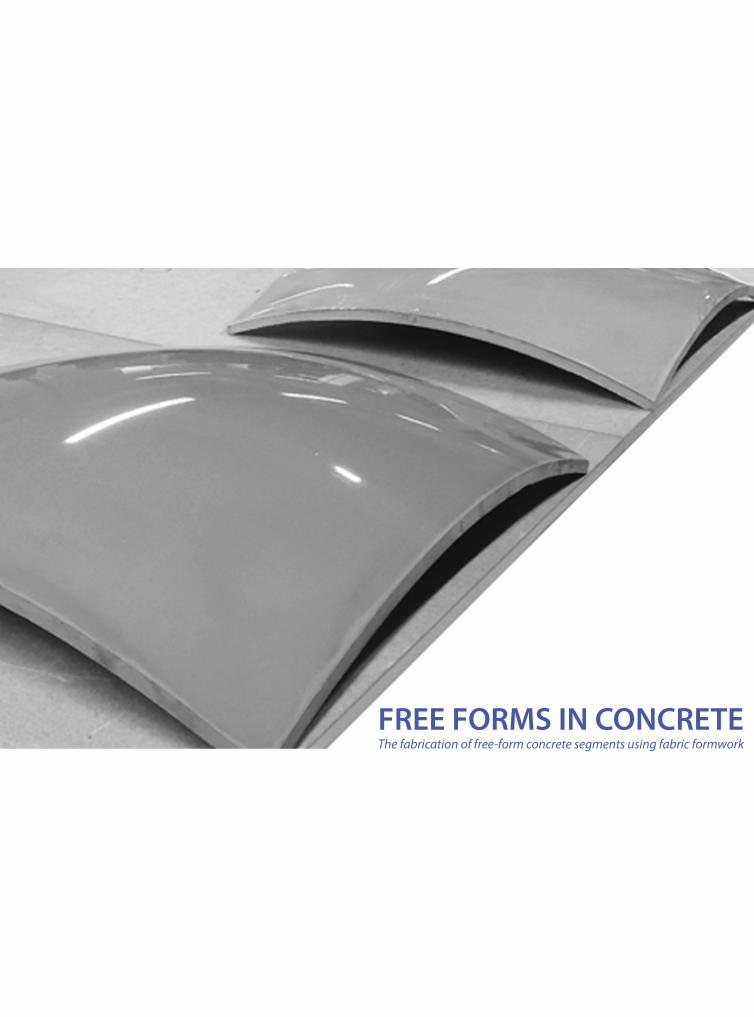
FREE FORMS IN CONCRETEThe fabrication of free-form concrete segments using fabric formwork


Free Forms in ConcreteThe fabrication of free-form concrete segments using fabric formwork
R.W.A. Verhaegh0532774
Graduating committ ee:
Prof. ir. F. v. HerwijnenProf. dr. ir. D. Hordijk (chairman)Ir. G. Lindnerdr. -Ing. G. Zimmermann
Eindhoven University of TechnologyDepartment of Architecture, Building and PlanningMastertrack Structural Design


Preface


7
Ten years ago, I took a trip to Madrid as part of an exchange-program with some Spanish students. On the way over, my teachers decided to make a quick stop in Bilbao. We only had a few hours to spare, so we drove straight to the real purpose of our visit: Gehry’s recently completed Guggenheim Museum. I remember being blown away by the apparent chaos of the building, which was somehow sewn together by fl uent lines and curved surfaces.When trying to decide on a subject for my master’s thesis, I discovered that the roots of ‘free-form architecture’ originate way before the Bilbao Guggenheim. My att ention was grasped by the work of Pier-Luigi Nervi, Heinz Isler and Félix Candela and other pioneers of the thin shell-structures. Their dedication to true multidisciplinary design led to some of the highest regarded architectural achievements of the twentieth century.Inspired by their approach to the building practice, I started researching the contemporary construction of free forms in concrete. I found an interesting alternative to the existing formwork-systems in the application of ‘fabric fomwork’. In researching this technique, I have att empted to tackle a practical problem in the construction of free forms. This has led to a highly experimental research, in which I have explored many aspects of building: not only structural design, but architecture, construction technology and building technology as well. This broad research has formed a suitable end to my education at the TU/e in which multidisciplinary design has always been stimulated. I would like to thank the members of my graduating committ ee for their support and cooperation during this project. They have continued to challenge me to explore all possible options, while at the same time forcing me to put my discoveries in the perspective of an actual building process.wAlso, I would like to thank my family and friends for their continuous support and interest in my work, but also for distracting me from it from time to time.Finally, I would like to thank my parents, Ans and Jos Verhaegh, for everything they have done to help me get to this point in my life. I am deeply grateful for your continuous support and stimulation.
Rob VerhaeghEindhoven, August 2010


Summary

11
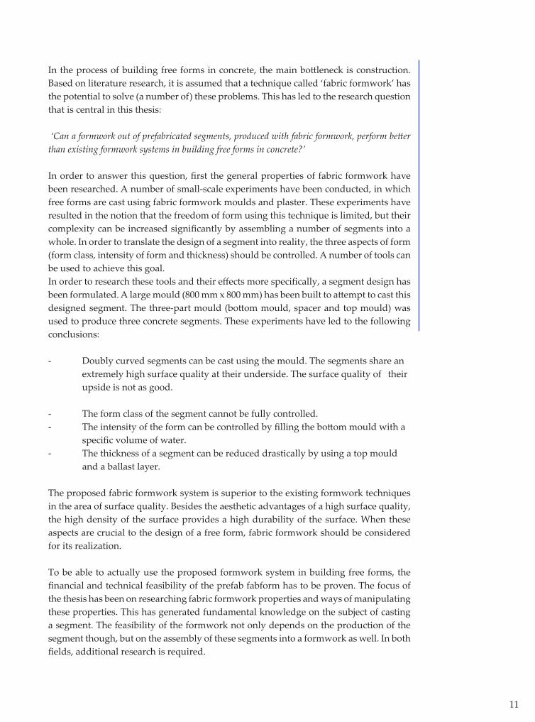
In the process of building free forms in concrete, the main bott leneck is construction. Based on literature research, it is assumed that a technique called ‘fabric formwork’ has the potential to solve (a number of) these problems. This has led to the research question that is central in this thesis:
‘Can a formwork out of prefabricated segments, produced with fabric formwork, perform bett er than existing formwork systems in building free forms in concrete?’
In order to answer this question, fi rst the general properties of fabric formwork have been researched. A number of small-scale experiments have been conducted, in which free forms are cast using fabric formwork moulds and plaster. These experiments have resulted in the notion that the freedom of form using this technique is limited, but their complexity can be increased signifi cantly by assembling a number of segments into a whole. In order to translate the design of a segment into reality, the three aspects of form (form class, intensity of form and thickness) should be controlled. A number of tools can be used to achieve this goal.In order to research these tools and their eff ects more specifi cally, a segment design has been formulated. A large mould (800 mm x 800 mm) has been built to att empt to cast this designed segment. The three-part mould (bott om mould, spacer and top mould) was used to produce three concrete segments. These experiments have led to the following conclusions:
- Doubly curved segments can be cast using the mould. The segments share an extremely high surface quality at their underside. The surface quality of their upside is not as good.
- The form class of the segment cannot be fully controlled.- The intensity of the form can be controlled by fi lling the bott om mould with a specifi c volume of water.- The thickness of a segment can be reduced drastically by using a top mould and a ballast layer. The proposed fabric formwork system is superior to the existing formwork techniques in the area of surface quality. Besides the aesthetic advantages of a high surface quality, the high density of the surface provides a high durability of the surface. When these aspects are crucial to the design of a free form, fabric formwork should be considered for its realization.
To be able to actually use the proposed formwork system in building free forms, the fi nancial and technical feasibility of the prefab fabform has to be proven. The focus of the thesis has been on researching fabric formwork properties and ways of manipulating these properties. This has generated fundamental knowledge on the subject of casting a segment. The feasibility of the formwork not only depends on the production of the segment though, but on the assembly of these segments into a formwork as well. In both fi elds, additional research is required.

12
13
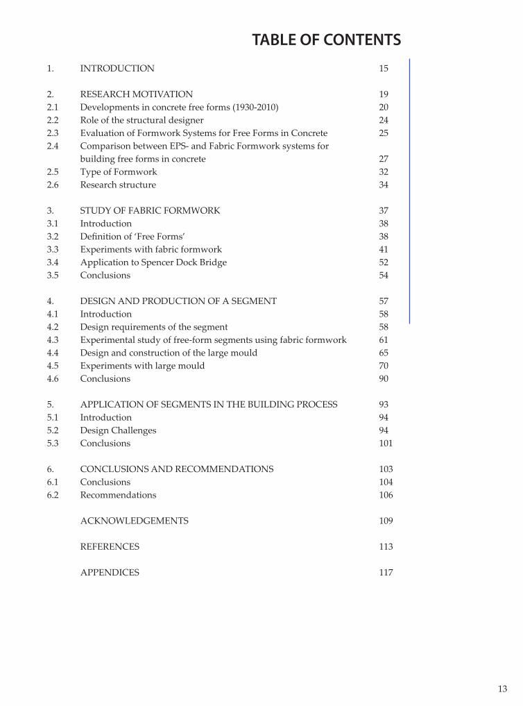
TABLE OF CONTENTS
1. INTRODUCTION 15 2. RESEARCH MOTIVATION 192.1 Developments in concrete free forms (1930-2010) 202.2 Role of the structural designer 242.3 Evaluation of Formwork Systems for Free Forms in Concrete 252.4 Comparison between EPS- and Fabric Formwork systems for building free forms in concrete 272.5 Type of Formwork 322.6 Research structure 34
3. STUDY OF FABRIC FORMWORK 373.1 Introduction 383.2 Defi nition of ‘Free Forms’ 383.3 Experiments with fabric formwork 413.4 Application to Spencer Dock Bridge 523.5 Conclusions 54
4. DESIGN AND PRODUCTION OF A SEGMENT 574.1 Introduction 584.2 Design requirements of the segment 584.3 Experimental study of free-form segments using fabric formwork 614.4 Design and construction of the large mould 654.5 Experiments with large mould 704.6 Conclusions 90
5. APPLICATION OF SEGMENTS IN THE BUILDING PROCESS 935.1 Introduction 945.2 Design Challenges 945.3 Conclusions 101
6. CONCLUSIONS AND RECOMMENDATIONS 1036.1 Conclusions 1046.2 Recommendations 106
ACKNOWLEDGEMENTS 109 REFERENCES 113
APPENDICES 117


1. Introduction

17
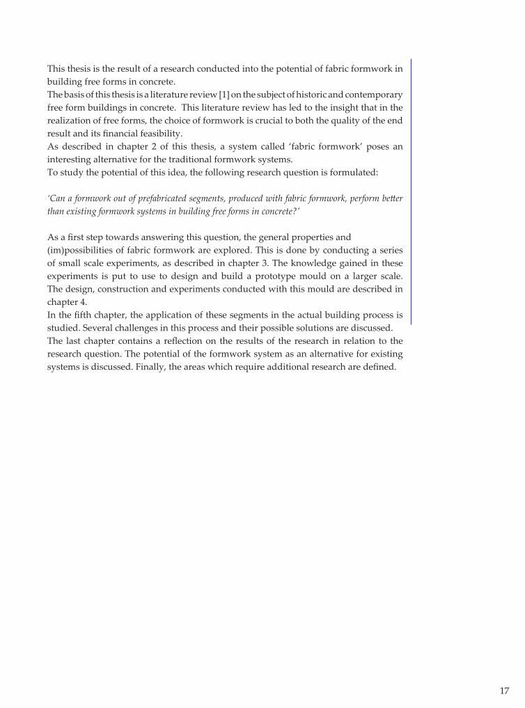
This thesis is the result of a research conducted into the potential of fabric formwork in building free forms in concrete. The basis of this thesis is a literature review [1] on the subject of historic and contemporary free form buildings in concrete. This literature review has led to the insight that in the realization of free forms, the choice of formwork is crucial to both the quality of the end result and its fi nancial feasibility. As described in chapter 2 of this thesis, a system called ‘fabric formwork’ poses an interesting alternative for the traditional formwork systems. To study the potential of this idea, the following research question is formulated:
‘Can a formwork out of prefabricated segments, produced with fabric formwork, perform bett er than existing formwork systems in building free forms in concrete?’
As a fi rst step towards answering this question, the general properties and (im)possibilities of fabric formwork are explored. This is done by conducting a series of small scale experiments, as described in chapter 3. The knowledge gained in these experiments is put to use to design and build a prototype mould on a larger scale. The design, construction and experiments conducted with this mould are described in chapter 4.In the fi fth chapter, the application of these segments in the actual building process is studied. Several challenges in this process and their possible solutions are discussed.The last chapter contains a refl ection on the results of the research in relation to the research question. The potential of the formwork system as an alternative for existing systems is discussed. Finally, the areas which require additional research are defi ned.


2. Research motivation
20
2.1 Developments in concrete free forms (1930-2010)
2.1.1 IntroductionAlthough concrete free forms seem to have gained popularity in the last decade, they have been around for far longer. This paragraph summarizes their history, based on the information that is gathered in the literature review ‘Free Forms in Concrete’ [1].
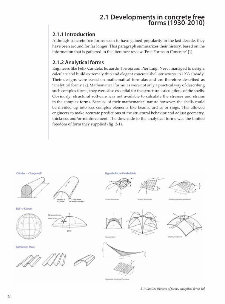
2.1.2 Analytical formsEngineers like Felix Candela, Eduardo Torroja and Pier Luigi Nervi managed to design, calculate and build extremely thin and elegant concrete shell-structures in 1933 already. Their designs were based on mathematical formulas and are therefore described as ‘analytical forms’ [2]. Mathematical formulas were not only a practical way of describing such complex forms, they were also essential for the structural calculations of the shells. Obviously, structural software was not available to calculate the stresses and strains in the complex forms. Because of their mathematical nature however, the shells could be divided up into less complex elements like beams, arches or rings. This allowed engineers to make accurate predictions of the structural behavior and adjust geometry, thickness and/or reinforcement. The downside to the analytical forms was the limited freedom of form they supplied (fi g. 2-1).
2-1: Limited freedom of forms, analytical forms [a]
21
The majority of the shells were constructed by pouring concrete onto a wooden formwork. The construction of this formwork required a large workforce of experienced craftsmen. Complex double-curved forms could be subdivided into linear elements, which made it possible to construct a formwork out of straight boards.
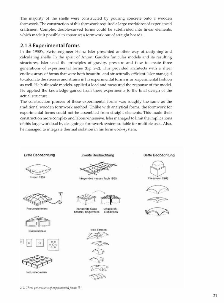
2.1.3 Experimental formsIn the 1950’s, Swiss engineer Heinz Isler presented another way of designing and calculating shells. In the spirit of Antoni Gaudi’s funicular models and its resulting structures, Isler used the principles of gravity, pressure and fl ow to create three generations of experimental forms (fi g. 2-2). This provided architects with a sheer endless array of forms that were both beautiful and structurally effi cient. Isler managed to calculate the stresses and strains in his experimental forms in an experimental fashion as well. He built scale models, applied a load and measured the response of the model. He applied the knowledge gained from these experiments to the fi nal design of the actual structure. The construction process of these experimental forms was roughly the same as the traditional wooden formwork method. Unlike with analytical forms, the formwork for experimental forms could not be assembled from straight elements. This made their construction more complex and labour-intensive. Isler managed to limit the implications of this large workload by designing a formwork-system suitable for multiple uses. Also, he managed to integrate thermal isolation in his formwork-system.
2-2: Three generations of experimental forms [b]

22
2.1.4 Digital forms
The 1990’s saw an increase in att ention for free form structures. The rapid development of computers and software off ered new possibilities for architects and structural engineers. These innovations made free-form design possible for a larger group of designers than ever before. They were provided with complete freedom in drawing a form, which resulted in a wide array of free form-structures. Digital forms are designed using CAD (computer aided design). The structural calculations are executed with relative ease and great accuracy by using FEM-based (fi nite elements method) software. Despite of the innovative formwork-systems on the market, the largest fraction of digital forms is still built using a ‘traditional’ wooden formwork.
2.1.5 ConclusionsIt is tempting to consider the three categories as three consecutive steps in the evolution of the free-form structure. That would imply that a digital form is superior to an experimental form, which in its turn is superior to an analytical form. This is not the case though. If the dominant category of free forms is projected onto a timeline of the 20th century, the relationship between the three categories becomes clear. All three of them have had their high- and low points in time, often connected to the high-point of the career of an infl uential designer or engineer. They should be seen as diff erent approaches to the same theme; each with its own strengths and weaknesses. Analytical forms are mathematically pure and therefore less diffi cult to calculate; experimental forms are structurally pure and therefore very effi cient and digital forms off er an unprecedented freedom of form. Anno 2010, buildings in all three categories are still being designed and realized (fi g 2-3).The history of free forms in concrete teaches that successful examples are, without exception, the result of a highly integrated design- and building process. The majority of contemporary free forms are designed based on aesthetic and spatial arguments. Therefore, the architect is the leading designer, forcing the structural designer and construction specialist in a supporting role. This observation leads to the following theorem:
Integrated design should be stimulated. This can be achieved by making architect, structural designer and construction specialist cooperate in an early stage of the building process.

23
2-3: History of Free Forms [1]

24
2.2 Role of the structural designer
Taking the theorem from §2.1.5 as a starting point, two questions arise: in what way can it be applied to the building of free forms in concrete, and what is the role of the structural designer in this process? In an att empt to answer these questions, the history of free forms is considered yet again.
When the role of the architect is analyzed, it becomes clear that the array of available design-tools has expanded during the 20th century. In the beginning of the century, architects were struggling with the new possibilities that reinforced concrete off ered them. The structural designers who were more experienced with the possibilities of this material led the way in the design process. As the century progressed, architects caught up and began to design more complex structures, making the structural designer’s job exceedingly diffi cult. The rise of computer and software fi nally enabled the architects to design a sheer endless array of forms and has enabled the structural designer to calculate these structures. Due to technical innovations, the possibilities of both the architect and structural designer have increased immensely. The construction of free forms though, is characterized by a lack of innovation. Today’s most popular formwork systems are largely the same as the systems used 80 years ago (fi g. 2-4). Unfortunately, the cost of labour is not. Since the wooden formwork systems rely heavily on a large and skilled workforce, the cost of labor proves to be the main limitation in building free forms. The development of an alternative formwork system could reduce this limitation. To design such a system would be an assignment on the border between aesthetics and technology; on the one hand, free forms are often extremely sensitive to small fl aws in surface quality or form. On the other hand a technological solution is required that is neither labour-intensive nor expensive. A structural designer is perfectly suited for this type of assignment. He or she is educated to be able to value aesthetics, but also has the technical knowledge to fi nd technological solutions for the challenges at hand.
2-4: Formwork of Cement Hall (left) and bycicle parking facility (right) [c]

25
2.3 Evaluation of Formwork Systems for Free Forms in Concrete
To be able to improve the existing formwork systems or design a new one, it is necessary to evaluate the existing systems. In the literature review [1], a large number of formwork systems are described. To assess and compare these systems, relevant criteria have to be formulated. The following criteria have been formulated:
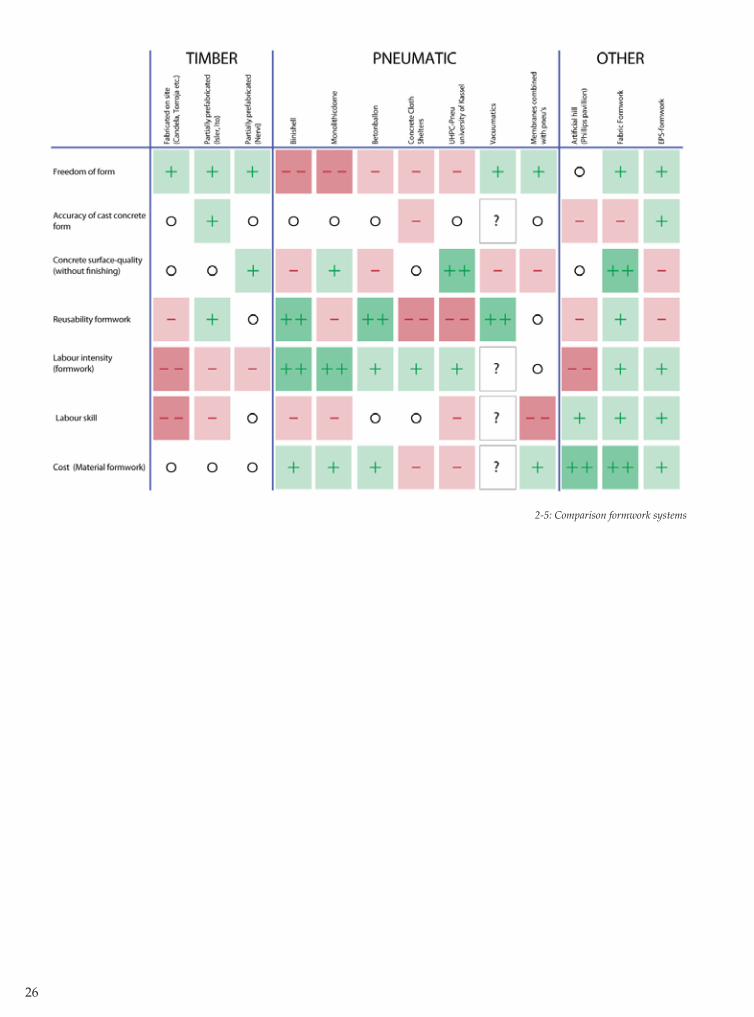
1. Freedom of Form – expresses the variety of possible types of form per system2. Accuracy of cast concrete form – Expresses the magnitude of the deviations that are to be expected using the system.3. Concrete surface quality – Expresses the aesthetic appeal of the concrete surface, without post-treatment. 4. Reusability formwork - Expresses the possibility for re-use of entire systems or recycling of parts of it.5. Labour intensity (formwork)- Expresses the total fte’s needed in relation to the magnitude of the building. 6. Labour skill – Expresses the need for specially skilled laborers on site in the building process.7. Cost – Expresses the cost of the materials used for the formwork system, in relation to the magnitude of the building.
The described systems are assessed on a scale from very bad (--) to very good (++) on each of these seven criteria. The assessment of each system is based on the examples that have been reviewed in the literature review. The results have been incorporated into a scheme (fi g. 2-5).
Generally speaking, the timber systems perform well, but are labour-intensive and therefore expensive. The pneumatic systems posses opposite properties; it is relatively easy to build free forms using pneu’s, but the freedom of form is limited. Artifi cial hills are no longer feasible due to extreme labour-intensity. This leaves two interesting systems: fabric formwork and EPS-formwork. On fi rst glance, both systems have some interesting properties. Where EPS-formwork off ers a higher accuracy, fabric formwork off ers bett er surface-quality and reusability. The biggest diff erence however is the low-tech approach of the fabric formwork-system in comparison to the computer-driven EPS-molding systems. Both systems off er signifi cant advantages over timber and pneumatic systems.
The qualifi cations in the scheme express the global qualities and weaknesses of a system. However, no two buildings are the same, especially not in free form design. To make a meaningful comparison between EPS and fabric formwork, it is necessary to make a further analysis of both systems.
26
2-5: Comparison formwork systems
27
2.4 Comparison between EPS- and Fabric Formwork systems for building free forms in
concrete
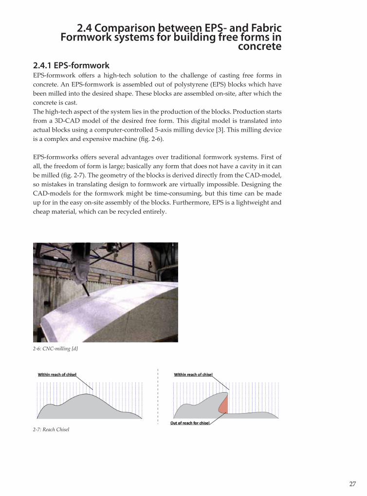
2.4.1 EPS-formworkEPS-formwork off ers a high-tech solution to the challenge of casting free forms in concrete. An EPS-formwork is assembled out of polystyrene (EPS) blocks which have been milled into the desired shape. These blocks are assembled on-site, after which the concrete is cast. The high-tech aspect of the system lies in the production of the blocks. Production starts from a 3D-CAD model of the desired free form. This digital model is translated into actual blocks using a computer-controlled 5-axis milling device [3]. This milling device is a complex and expensive machine (fi g. 2-6).
EPS-formworks off ers several advantages over traditional formwork systems. First of all, the freedom of form is large; basically any form that does not have a cavity in it can be milled (fi g. 2-7). The geometry of the blocks is derived directly from the CAD-model, so mistakes in translating design to formwork are virtually impossible. Designing the CAD-models for the formwork might be time-consuming, but this time can be made up for in the easy on-site assembly of the blocks. Furthermore, EPS is a lightweight and cheap material, which can be recycled entirely.
2-6: CNC-milling [d]
2-7: Reach Chisel
28
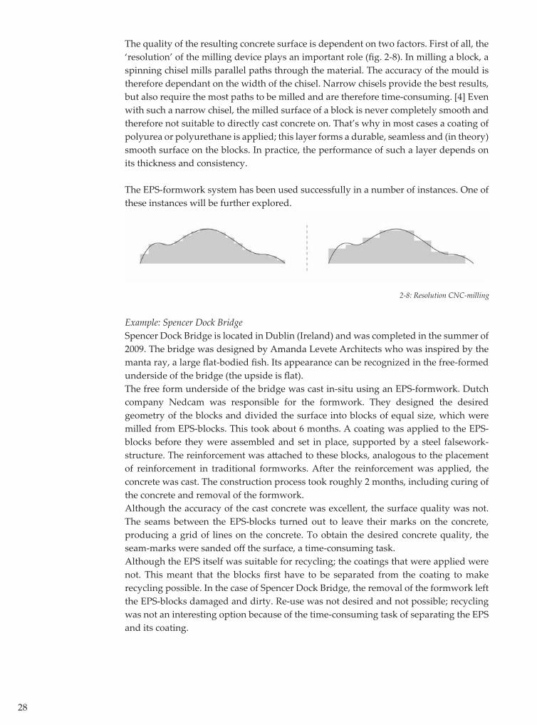
The quality of the resulting concrete surface is dependent on two factors. First of all, the ‘resolution’ of the milling device plays an important role (fi g. 2-8). In milling a block, a spinning chisel mills parallel paths through the material. The accuracy of the mould is therefore dependant on the width of the chisel. Narrow chisels provide the best results, but also require the most paths to be milled and are therefore time-consuming. [4] Even with such a narrow chisel, the milled surface of a block is never completely smooth and therefore not suitable to directly cast concrete on. That’s why in most cases a coating of polyurea or polyurethane is applied; this layer forms a durable, seamless and (in theory) smooth surface on the blocks. In practice, the performance of such a layer depends on its thickness and consistency.
The EPS-formwork system has been used successfully in a number of instances. One of these instances will be further explored.
Example: Spencer Dock BridgeSpencer Dock Bridge is located in Dublin (Ireland) and was completed in the summer of 2009. The bridge was designed by Amanda Levete Architects who was inspired by the manta ray, a large fl at-bodied fi sh. Its appearance can be recognized in the free-formed underside of the bridge (the upside is fl at). The free form underside of the bridge was cast in-situ using an EPS-formwork. Dutch company Nedcam was responsible for the formwork. They designed the desired geometry of the blocks and divided the surface into blocks of equal size, which were milled from EPS-blocks. This took about 6 months. A coating was applied to the EPS-blocks before they were assembled and set in place, supported by a steel falsework-structure. The reinforcement was att ached to these blocks, analogous to the placement of reinforcement in traditional formworks. After the reinforcement was applied, the concrete was cast. The construction process took roughly 2 months, including curing of the concrete and removal of the formwork. Although the accuracy of the cast concrete was excellent, the surface quality was not. The seams between the EPS-blocks turned out to leave their marks on the concrete, producing a grid of lines on the concrete. To obtain the desired concrete quality, the seam-marks were sanded off the surface, a time-consuming task. Although the EPS itself was suitable for recycling; the coatings that were applied were not. This meant that the blocks fi rst have to be separated from the coating to make recycling possible. In the case of Spencer Dock Bridge, the removal of the formwork left the EPS-blocks damaged and dirty. Re-use was not desired and not possible; recycling was not an interesting option because of the time-consuming task of separating the EPS and its coating.
2-8: Resolution CNC-milling

29
2-9: Spencer Dock Bridge [e]
2-10: Underside of Spencer Dock Bridge [e]
30
2.4.2 Fabric Formwork
Fabric formwork (or fabform) is a formwork system in which the surface of the formwork is not made out of a rigid material like wood or polystyrene, but out of a fl exible fabric. The advantage of a fl exible material is that it is relatively easy to shape into a free form. There are no examples of fabform being used for building free forms on a large scale, but the experiments that have been conducted until now show that the system might have the potential to solve some problems that occur in building free forms.Although a lot of properties, when judged by the criteria from the scheme will diff er per project, some properties are inherent for fabform: the surface quality of the fabform-concrete is very good and the fabric material is lightweight, relatively cheap and reusable.
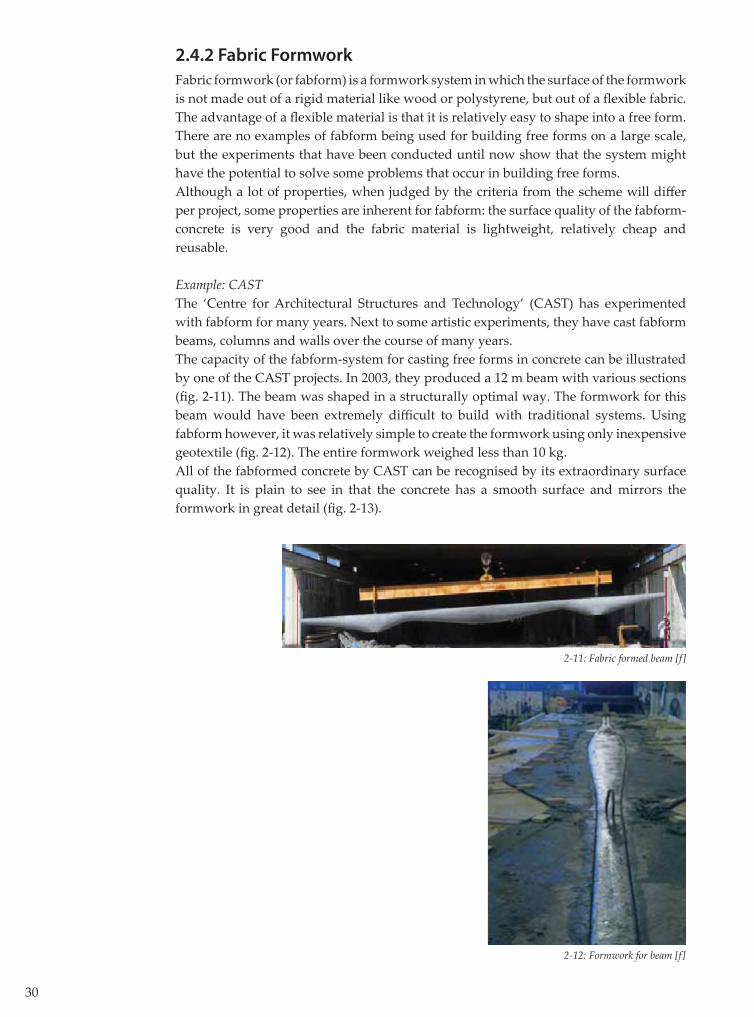
Example: CAST The ‘Centre for Architectural Structures and Technology’ (CAST) has experimented with fabform for many years. Next to some artistic experiments, they have cast fabform beams, columns and walls over the course of many years. The capacity of the fabform-system for casting free forms in concrete can be illustrated by one of the CAST projects. In 2003, they produced a 12 m beam with various sections (fi g. 2-11). The beam was shaped in a structurally optimal way. The formwork for this beam would have been extremely diffi cult to build with traditional systems. Using fabform however, it was relatively simple to create the formwork using only inexpensive geotextile (fi g. 2-12). The entire formwork weighed less than 10 kg.All of the fabformed concrete by CAST can be recognised by its extraordinary surface quality. It is plain to see in that the concrete has a smooth surface and mirrors the formwork in great detail (fi g. 2-13).
2-12: Formwork for beam [f]
2-11: Fabric formed beam [f]

31
2.4.3 Conclusions
The EPS formwork system off ers signifi cant advantages over any other formwork system. Its limitations though, lie in the necessity for complex equipment, the resulting ‘less-than-perfect’ surface quality and the (in)ability to re-use or recycle.In theory, it is possible that all of these disadvantages could be avoided by using the fabric formwork-system. One of the strong points of fabform is its superior surface-quality. Also, the actual surface of the formwork is the fabric, which is light and relatively cheap. If the fabric is loaded in its elastic range, the material will return to its original state after the casting, making it ideal for re-use. The lack of suitable examples in which fabform is used for large scale free form buildings makes it hard to adequately compare the system to the EPS-formwork system. To do so, additional research is required. To conduct this additional research, a framework has to be created in which the two systems can be compared in equal circumstances. These equal circumstances can be found by subjecting them to the same case-study. Because EPS-formwork has already been used to build Spencer Dock Bridge in reality, this project is used as a case-study for the fabform system as well.
2-13: Surface Quality Fabform [f]
32
2.5 Type of Formwork
The fi rst step towards making an adequate comparison between the two systems lies in establishing the manner in which the fabform is going to be used. In general, concrete structures can be built in two ways. The concrete can be cast on the site itself (in-situ), or the concrete can be cast in segments in the factory, after which these segments are transported to the site (prefab).
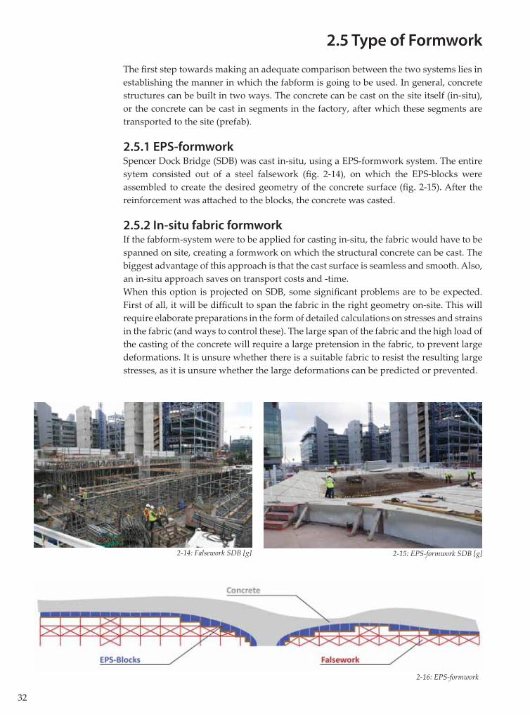
2.5.1 EPS-formwork Spencer Dock Bridge (SDB) was cast in-situ, using a EPS-formwork system. The entire sytem consisted out of a steel falsework (fi g. 2-14), on which the EPS-blocks were assembled to create the desired geometry of the concrete surface (fi g. 2-15). After the reinforcement was att ached to the blocks, the concrete was casted.
2.5.2 In-situ fabric formworkIf the fabform-system were to be applied for casting in-situ, the fabric would have to be spanned on site, creating a formwork on which the structural concrete can be cast. The biggest advantage of this approach is that the cast surface is seamless and smooth. Also, an in-situ approach saves on transport costs and -time. When this option is projected on SDB, some signifi cant problems are to be expected. First of all, it will be diffi cult to span the fabric in the right geometry on-site. This will require elaborate preparations in the form of detailed calculations on stresses and strains in the fabric (and ways to control these). The large span of the fabric and the high load of the casting of the concrete will require a large pretension in the fabric, to prevent large deformations. It is unsure whether there is a suitable fabric to resist the resulting large stresses, as it is unsure whether the large deformations can be predicted or prevented.
2-14: Falsework SDB [g] 2-15: EPS-formwork SDB [g]
2-16: EPS-formwork
33
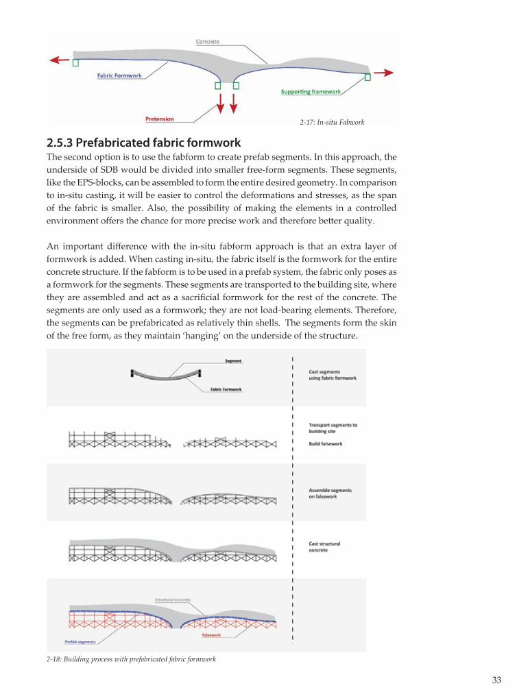
2.5.3 Prefabricated fabric formworkThe second option is to use the fabform to create prefab segments. In this approach, the underside of SDB would be divided into smaller free-form segments. These segments, like the EPS-blocks, can be assembled to form the entire desired geometry. In comparison to in-situ casting, it will be easier to control the deformations and stresses, as the span of the fabric is smaller. Also, the possibility of making the elements in a controlled environment off ers the chance for more precise work and therefore bett er quality.
An important diff erence with the in-situ fabform approach is that an extra layer of formwork is added. When casting in-situ, the fabric itself is the formwork for the entire concrete structure. If the fabform is to be used in a prefab system, the fabric only poses as a formwork for the segments. These segments are transported to the building site, where they are assembled and act as a sacrifi cial formwork for the rest of the concrete. The segments are only used as a formwork; they are not load-bearing elements. Therefore, the segments can be prefabricated as relatively thin shells. The segments form the skin of the free form, as they maintain ‘hanging’ on the underside of the structure.
2-17: In-situ Fabwork
2-18: Building process with prefabricated fabric formwork
34
2.5.4 Conclusion
After this global analysis, the chance of success seems largest when using prefab elements. The rest of this research will therefore focus on the building of free forms in concrete, using prefab elements produced with fabric formwork. This does not mean that the in-situ option can be discarded; this option might very well be a feasible solution to the problem at hand as well. It is to be recommended that this option will be the subject of further research.The prefab fabform-system is possibly superior to the EPS-formwork system in the areas of surface quality, reusability and cost (material formwork).
2.6 Research structure
2.6.1 Research questionIn the previous paragraphs and the literature review [1], some problems have been established in building free forms in concrete. Based on literature research, it is assumed that a formwork system of prefab fabform segments has the potential to (partially) solve these problems. This leads to the research question that is central in this thesis:
‘Can a formwork out of prefabricated segments, produced with fabric formwork, perform bett er than existing formwork systems in building free forms in concrete?’
This question can only be answered adequately by researching and developing the system in great detail. For practical reasons though, it is not possible to perform a full research into all of the aspects that determine the potential of the prefab fabform system within the framework of this thesis. It is possible though, to list those aspects and to choose a number of them to study. The quality of a formwork system can only be determined in relation to a project it is being applied to. The performance of the EPS-formwork for example, can be established in relation to Spencer Dock Bridge. To be able to compare the performance of the prefab fabform segments system, SDB will be used as a case-study. This means that the research will focus on the steps that would have to be taken to actually build SDB. These steps are grouped into three parts.
2.6.2 Sub-questions
Study of fabric formwork In order to determine the freedom of form that can be achieved using the prefab fabform system, the possibilities of fabric formwork have to be explored fi rst. In a series of small-scale experiments, the array of possible forms is established, as well as the ways to manipulate these forms. The goal of this study is to answer the sub-question:
‘What type of forms can be built using fabric formwork segments, and what tools can be used to control the production of these forms?’
35
Design and production of a segmentThe study of fabric formwork is meant to generate general knowledge on the properties and possibilities of fabform. However, the true possibilities of fabform can only be determined by using fabform to realize a free form. Therefore, a free form segment will be designed. In order to realize this design, a fabric formwork will be designed and built. Finally, a segment will be produced using this mould.The goal of the design and production of a segment is to answer the sub-question:
‘In what way can the design of a free form-segment be realized using a fabric formwork?’
Application of segments in the building processIf all of the required elements to assemble a free form were to be produced, there would still be a variety of challenges to overcome when actually using the proposed formwork system in building a free form. The segments would have to be transported to the building site, they would have to be assembled and supported before any reinforcement and concrete could be applied, etcetera. The application of the segments in the building process does not belong to the core of this thesis. The subject will not be researched in depth. However, it is not possible to compare a new formwork system to an existing one while ignoring the challenges of the building process. Therefore, these aspects are explored in a qualitative manner. This means that the aspects are listed, the respective challenges that they pose are assessed and solutions are proposed.
2.6.5 ConclusionsThe core of this thesis consists of generating knowledge on the subject of fabric formwork. The relevance of this knowledge will be continuously tested on the case-study Spencer Dock Bridge. This should result in a deeper insight into the properties and possibilities of fabform. It is not possible to fully answer the research question within the scope of this research. This thesis should therefore be read as an exploration of the potential of a new formwork system for constructing free forms.


3. Study of Fabric Formwork

38
3.1 Introduction
In this chapter, an answer to the following sub-question will be formulated:
‘What type of forms can be built using fabric formwork segments, and what tools can be used to control the production of these forms?’
To answer this question, a number of steps is undertaken. First, the term ‘free form’ is defi ned. The second step consists of undertaking a series of experiments. The results of these experiments lead to a general image of possible forms, and a list of tools for producing these forms. Subsequently, this knowledge is projected on the case-study Spencer Dock Bridge.
3.2 Defi nition of ‘Free Forms’
The term ‘free forms’ can be further defi ned by regarding a simple square. The surface of this square is defi ned by the shape of its four edges. When all of these edges are straight and fl at lines, the form of its surface is fl at as well. If two or more of the edges are inclining, the surface can still be fl at, but it can also become a doubly curved surface.
3-2 Curved surface from curved edges, Deitingen Gasstation, Heinz Isler [b]
3-1: Curved surface from inclining edges, Xochimilico Restaurant, Felix Candela [h]
39
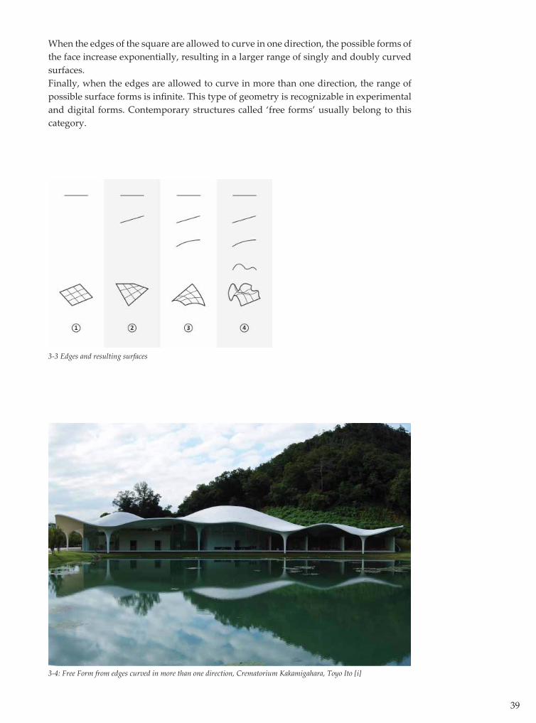
When the edges of the square are allowed to curve in one direction, the possible forms of the face increase exponentially, resulting in a larger range of singly and doubly curved surfaces. Finally, when the edges are allowed to curve in more than one direction, the range of possible surface forms is infi nite. This type of geometry is recognizable in experimental and digital forms. Contemporary structures called ‘free forms’ usually belong to this category.
3-3 Edges and resulting surfaces
3-4: Free Form from edges curved in more than one direction, Crematorium Kakamigahara, Toyo Ito [i]

40
Each time the complexity of the shape of the edges is increased, the amount of possible surface forms and their complexity increases. The entire range of possible surfaces is displayed and divided into four categories of (increasing) complexity (fi g. 3-5). Obviously, the most complex section displays only a fraction of the possible forms, as this section contains an infi nite amount of unique forms.
3-5: Range of possible free forms
41
3.3 Experiments with fabric formwork
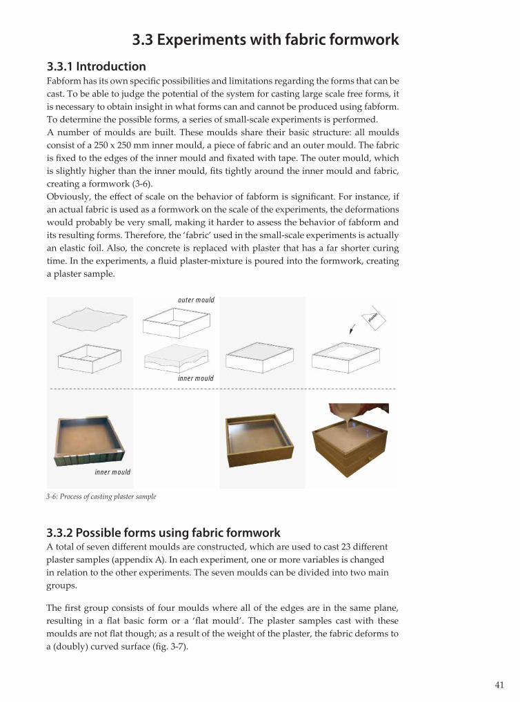
3.3.1 IntroductionFabform has its own specifi c possibilities and limitations regarding the forms that can be cast. To be able to judge the potential of the system for casting large scale free forms, it is necessary to obtain insight in what forms can and cannot be produced using fabform. To determine the possible forms, a series of small-scale experiments is performed.A number of moulds are built. These moulds share their basic structure: all moulds consist of a 250 x 250 mm inner mould, a piece of fabric and an outer mould. The fabric is fi xed to the edges of the inner mould and fi xated with tape. The outer mould, which is slightly higher than the inner mould, fi ts tightly around the inner mould and fabric, creating a formwork (3-6).Obviously, the eff ect of scale on the behavior of fabform is signifi cant. For instance, if an actual fabric is used as a formwork on the scale of the experiments, the deformations would probably be very small, making it harder to assess the behavior of fabform and its resulting forms. Therefore, the ‘fabric’ used in the small-scale experiments is actually an elastic foil. Also, the concrete is replaced with plaster that has a far shorter curing time. In the experiments, a fl uid plaster-mixture is poured into the formwork, creating a plaster sample.
3.3.2 Possible forms using fabric formworkA total of seven diff erent moulds are constructed, which are used to cast 23 diff erent plaster samples (appendix A). In each experiment, one or more variables is changed in relation to the other experiments. The seven moulds can be divided into two main groups.
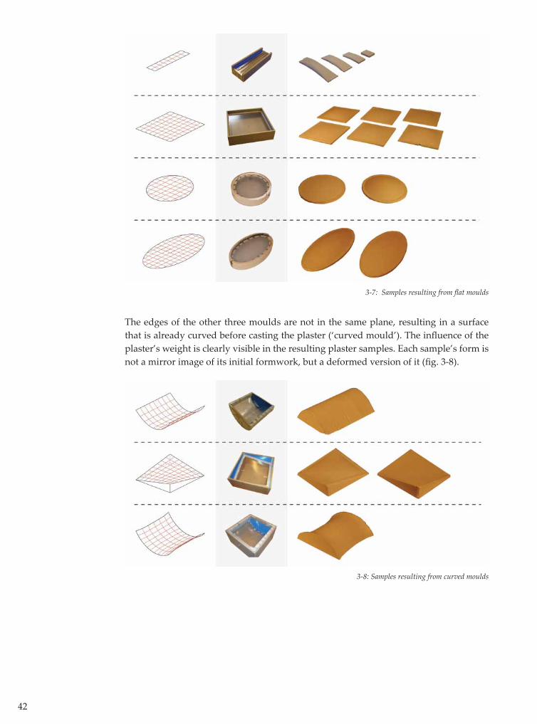
The fi rst group consists of four moulds where all of the edges are in the same plane, resulting in a fl at basic form or a ‘fl at mould’. The plaster samples cast with these moulds are not fl at though; as a result of the weight of the plaster, the fabric deforms to a (doubly) curved surface (fi g. 3-7).
3-6: Process of casting plaster sample
outer mould
inner mould
inner mould
42
3-7: Samples resulting from fl at moulds
3-8: Samples resulting from curved moulds
The edges of the other three moulds are not in the same plane, resulting in a surface that is already curved before casting the plaster (‘curved mould’). The infl uence of the plaster’s weight is clearly visible in the resulting plaster samples. Each sample’s form is not a mirror image of its initial formwork, but a deformed version of it (fi g. 3-8).
43
General ObservationsAn evaluation of the experiments leads to some general observations.
- The resulting plaster samples share an excellent surface quality. The surfaces are smooth and mirror the texture of the formwork foils in great detail. - The process of casting and demoulding the plaster proves to be quite easy. The plaster does not stick to the foil, which can be used again several times. - After use, the foil has to be freshly stretched over the mould in order to re-use it. The applied loads and the heat of the exothermic process of the curing of plaster cause plastic deformations of the foil.
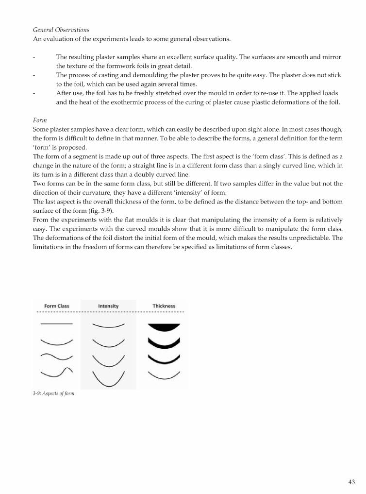
FormSome plaster samples have a clear form, which can easily be described upon sight alone. In most cases though, the form is diffi cult to defi ne in that manner. To be able to describe the forms, a general defi nition for the term ‘form’ is proposed.The form of a segment is made up out of three aspects. The fi rst aspect is the ‘form class’. This is defi ned as a change in the nature of the form; a straight line is in a diff erent form class than a singly curved line, which in its turn is in a diff erent class than a doubly curved line. Two forms can be in the same form class, but still be diff erent. If two samples diff er in the value but not the direction of their curvature, they have a diff erent ‘intensity’ of form.The last aspect is the overall thickness of the form, to be defi ned as the distance between the top- and bott om surface of the form (fi g. 3-9).From the experiments with the fl at moulds it is clear that manipulating the intensity of a form is relatively easy. The experiments with the curved moulds show that it is more diffi cult to manipulate the form class. The deformations of the foil distort the initial form of the mould, which makes the results unpredictable. The limitations in the freedom of forms can therefore be specifi ed as limitations of form classes.
3-9: Aspects of form
44
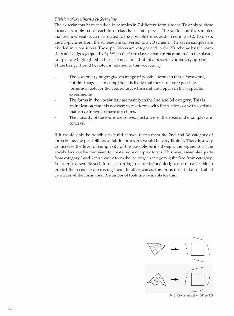
Division of experiments by form classThe experiments have resulted in samples in 7 diff erent form classes. To analyze these forms, a sample out of each form class is cut into pieces. The sections of the samples that are now visible, can be related to the possible forms as defi ned in §3.3.2. To do so, the 3D-pictures from the scheme are converted to a 2D scheme. The seven samples are divided into partitions. These partitions are categorized in the 2D scheme by the form class of its edges (appendix B). When the form classes that are encountered in the plaster samples are highlighted in the scheme, a fi rst draft of a possible vocabulary appears. Three things should be noted in relation to this vocabulary:
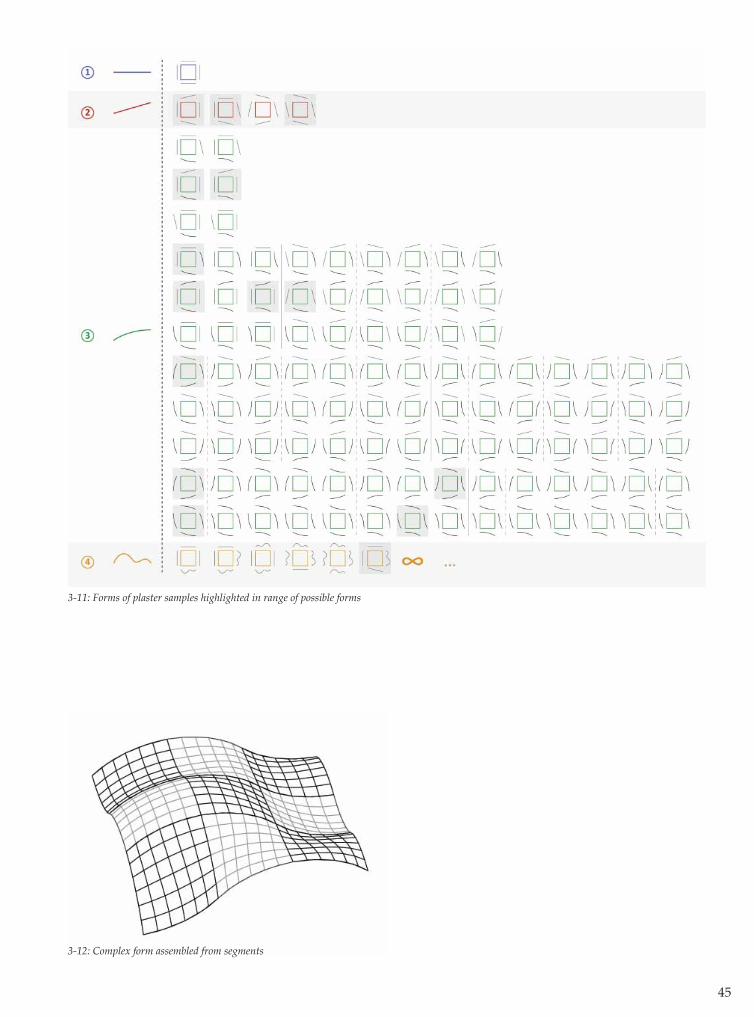
- The vocabulary might give an image of possible forms in fabric formwork, but this image is not complete. It is likely that there are more possible forms available for the vocabulary, which did not appear in these specifi c experiments.- The forms in the vocabulary are mainly in the 2nd and 3d category. This is an indication that it is not easy to cast forms with fl at sections or with sections that curve in two or more directions. - The majority of the forms are convex. Just a few of the areas of the samples are concave.
If it would only be possible to build convex forms from the 2nd and 3d category of the scheme, the possibilities of fabric formwork would be very limited. There is a way to increase the level of complexity of the possible forms though: the segments in the vocabulary can be combined to create more complex forms. This way, assembled parts from category 2 and 3 can create a form that belongs in category 4; the free-from category. In order to assemble such forms according to a predefi ned design, one must be able to predict the forms before casting them. In other words, the forms need to be controlled by means of the formwork. A number of tools are available for this.
3-10: Conversion from 3D to 2D
45
3-11: Forms of plaster samples highlighted in range of possible forms
3-12: Complex form assembled from segments
46
3.3.3 Tools of control
There are a number of ways in which the form of the plaster samples can be controlled or manipulated.The form of the fabform plaster samples is the product of an ‘equation’ that consists of a number of terms. These terms represent diff erent parts of the formwork system, like the properties of the fabric, the shape of the edges, the consistency of the plaster, etc. Some of these terms can be manipulated and become tools of control for the fi nal form of the samples. Tools of control can have a continuous or a discrete eff ect. If a tool has a continuous eff ect, it can be used to gradually change the form of the fabric (within its limits). If the eff ect is discrete, the form of the fabric can only be changed in steps. During the experiments, these tools have been tested and their eff ects have been studied.
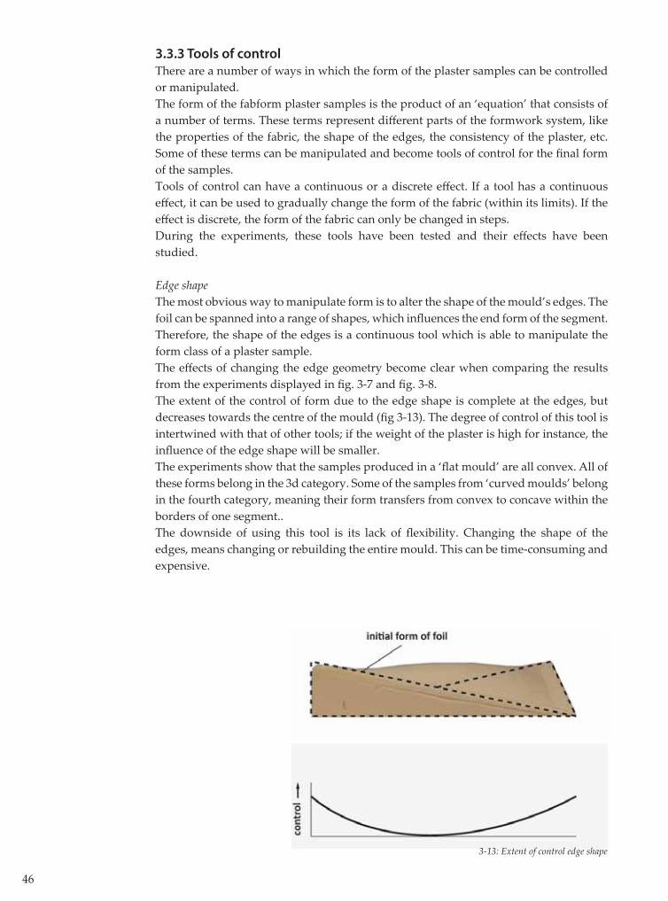
Edge shapeThe most obvious way to manipulate form is to alter the shape of the mould’s edges. The foil can be spanned into a range of shapes, which infl uences the end form of the segment. Therefore, the shape of the edges is a continuous tool which is able to manipulate the form class of a plaster sample. The eff ects of changing the edge geometry become clear when comparing the results from the experiments displayed in fi g. 3-7 and fi g. 3-8.The extent of the control of form due to the edge shape is complete at the edges, but decreases towards the centre of the mould (fi g 3-13). The degree of control of this tool is intertwined with that of other tools; if the weight of the plaster is high for instance, the infl uence of the edge shape will be smaller.The experiments show that the samples produced in a ‘fl at mould’ are all convex. All of these forms belong in the 3d category. Some of the samples from ‘curved moulds’ belong in the fourth category, meaning their form transfers from convex to concave within the borders of one segment.. The downside of using this tool is its lack of fl exibility. Changing the shape of the edges, means changing or rebuilding the entire mould. This can be time-consuming and expensive.
3-13: Extent of control edge shape

47
Edge supportWhen the foil is att ached to four sides of a mould, the load of the plaster will be transferred to all four of these edges, resulting in a characteristic deformation of the foil and form of the plaster sample. If the foil is att ached to just two of these edges though, the load will be transferred to these two sides, and the deformation will diff er from that of the fi rst example. Therefore, by altering the support of the foil, the form class can be manipulated. The eff ects of this tool are discrete: either an edge is supported or it is not.This is illustrated by the results from the experiments displayed in fi g. 3-14. In both experiments the same mould is used, but in the fi rst experiment, the foil was only fi xed to the straight edges, as the foil in the second example was fi xed to all edges. The fi rst experiment results in a singly curved sample, while the second experiment produces a doubly curved sample.
Although this tool is eff ective, it is not very practical. Sides of the fabric that are not supported, cannot prevent the gypsum from spilling out of the mould. Another disadvantage is the occurrence of wrinkles in the fabric. Because the fabric cannot be stretched in all directions, there is no way to get rid of its wrinkles. The wrinkles are clearly visible in the resulting plaster sample.
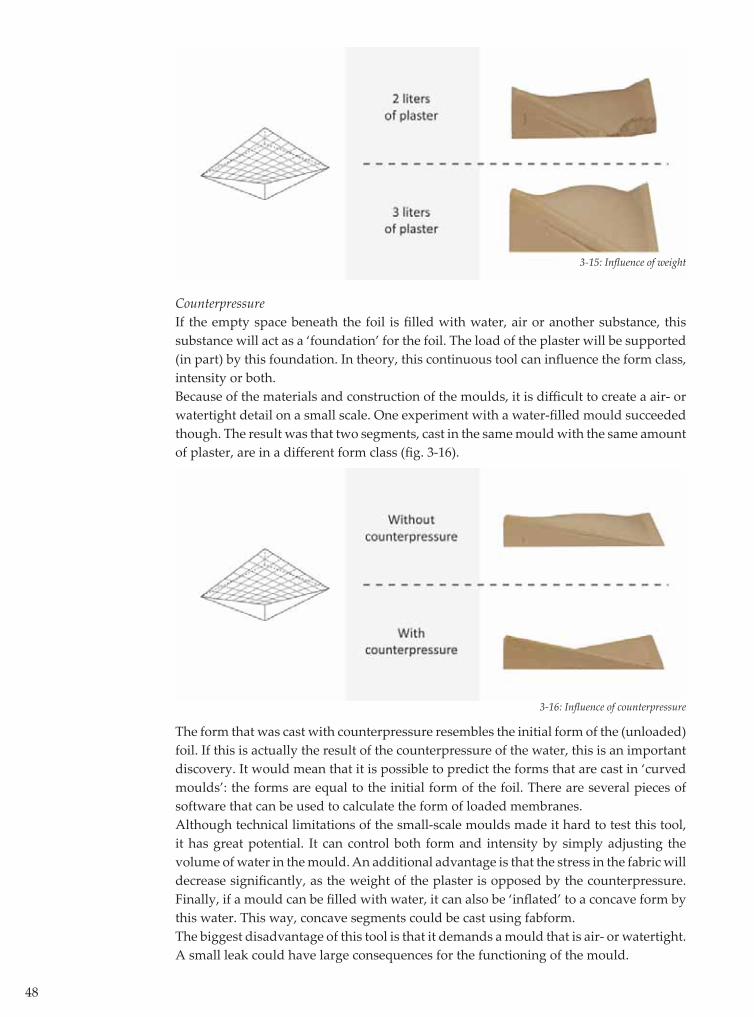
Weight During the casting, the foil is loaded by the weight of the plaster. As the weight increases, the deformation of the fabric increases as well. Depending on the initial form of the foil, this can infl uence the intensity of the form in a continuous way.This is illustrated by a set of experiments. The plaster samples in fi g 3-15 have both been cast in the same mould. The upper sample is the result of casting 2 liters of plaster, the bott om sample of casting 3 liters. The weight of the plaster is determined by the volume that is poured. This volume is preferably derived from the design of the desired segment. If it were to be derived from the necessary weight for a specifi c form, this would mean that a part of the plaster is ‘wasted’ on the manipulation of the form alone. This could be achieved by applying other, cheaper materials as well. Therefore, weight is only a usable tool of control if it originates from a ballast material which is either cheap, reusable or both.
3-14: Infl uence edge support
48
CounterpressureIf the empty space beneath the foil is fi lled with water, air or another substance, this substance will act as a ‘foundation’ for the foil. The load of the plaster will be supported (in part) by this foundation. In theory, this continuous tool can infl uence the form class, intensity or both. Because of the materials and construction of the moulds, it is diffi cult to create a air- or watertight detail on a small scale. One experiment with a water-fi lled mould succeeded though. The result was that two segments, cast in the same mould with the same amount of plaster, are in a diff erent form class (fi g. 3-16).
3-15: Infl uence of weight
3-16: Infl uence of counterpressure
The form that was cast with counterpressure resembles the initial form of the (unloaded) foil. If this is actually the result of the counterpressure of the water, this is an important discovery. It would mean that it is possible to predict the forms that are cast in ‘curved moulds’: the forms are equal to the initial form of the foil. There are several pieces of software that can be used to calculate the form of loaded membranes.Although technical limitations of the small-scale moulds made it hard to test this tool, it has great potential. It can control both form and intensity by simply adjusting the volume of water in the mould. An additional advantage is that the stress in the fabric will decrease signifi cantly, as the weight of the plaster is opposed by the counterpressure. Finally, if a mould can be fi lled with water, it can also be ‘infl ated’ to a concave form by this water. This way, concave segments could be cast using fabform.The biggest disadvantage of this tool is that it demands a mould that is air- or watertight. A small leak could have large consequences for the functioning of the mould.
49
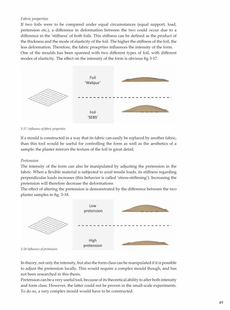
Fabric propertiesIf two foils were to be compared under equal circumstances (equal support, load, pretension etc.), a diff erence in deformation between the two could occur due to a diff erence in the ‘stiff ness’ of both foils. This stiff ness can be defi ned as the product of the thickness and the mode of elasticity of the foil. The higher the stiff ness of the foil, the less deformation. Therefore, the fabric proeprties infl uences the intensity of the form. One of the moulds has been spanned with two diff erent types of foil, with diff erent modes of elasticity. The eff ect on the intensity of the form is obvious fi g 3-17.
If a mould is constructed in a way that its fabric can easily be replaced by another fabric, than this tool would be useful for controlling the form as well as the aesthetics of a sample: the plaster mirrors the texture of the foil in great detail.
PretensionThe intensity of the form can also be manipulated by adjusting the pretension in the fabric. When a fl exible material is subjected to axial tensile loads, its stiff ness regarding perpendicular loads increases (this behavior is called ‘stress-stiff ening’). Increasing the pretension will therefore decrease the deformationsThe eff ect of altering the pretension is demonstrated by the diff erence between the two plaster samples in fi g. 3-18.
3-17: Infl uence of fabric properties
In theory, not only the intensity, but also the form class can be manipulated if it is possible to adjust the pretension locally. This would require a complex mould though, and has not been researched in this thesis.Pretension can be a very useful tool, because of its theoretical ability to alter both intensity and form class. However, the latt er could not be proven in the small-scale experiments. To do so, a very complex mould would have to be constructed.
3-18 Infl uence of pretension
50
SpanThe most basic way to decrease the deformation of any structure is to decrease its span. By doing so, not only the deformation is altered, the curvature is as well. The span of a foil is therefore a continuous tool to manipulate the intensity the form.This eff ect is demonstrated in a series of experiments. A mould was made in which the span could easily be altered. Because only two edges were supported, singly curved plaster samples were cast in this mould. The results of these experiments were arranged so the eff ect on the curvature is clear (fi g. 3-19).
3-19: Curvature of plaster samples can be controlled by adjusting the span of the mould
3-20: Infl uence of countermould
This tool is probably not very useful in a large fabric formwork. The size and span of a segment are more likely to be derived from the design of the free form.
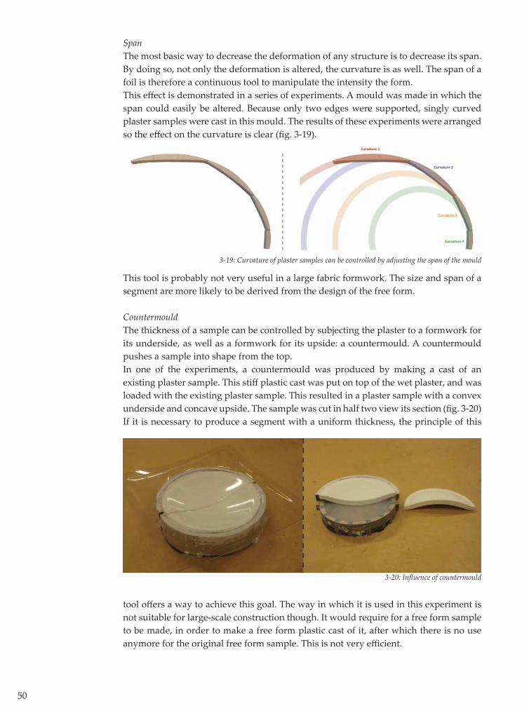
CountermouldThe thickness of a sample can be controlled by subjecting the plaster to a formwork for its underside, as well as a formwork for its upside: a countermould. A countermould pushes a sample into shape from the top.In one of the experiments, a countermould was produced by making a cast of an existing plaster sample. This stiff plastic cast was put on top of the wet plaster, and was loaded with the existing plaster sample. This resulted in a plaster sample with a convex underside and concave upside. The sample was cut in half two view its section (fi g. 3-20)If it is necessary to produce a segment with a uniform thickness, the principle of this
tool off ers a way to achieve this goal. The way in which it is used in this experiment is not suitable for large-scale construction though. It would require for a free form sample to be made, in order to make a free form plastic cast of it, after which there is no use anymore for the original free form sample. This is not very effi cient.

51
3-21 Tools of control

52
3.4 Application to Spencer Dock Bridge
The free form underside of SDB is to be divided up into a number of segments, which can be prefabricated with fabric formwork. There are an infi nite number of ways to divide a surface into smaller surfaces. The experience from the experiments can help to decide which way to choose.Samples (or segments) from fl at moulds are easier to control than segments from curved moulds. Therefore, it would be a good idea to segment SDB into segments that can be made using fl at moulds. Flat moulds produce samples that are either convex or concave. Their forms do not transfer from convex to concave within the boundaries of just one sample. Keeping this in mind, it makes sense to divide SDB into convex and concave segments. This way, each connection between segments is a point of infl ection from a concave to a convex form. This segmentation can theoretically be achieved by connecting the points of infl ection of the sections of a form. The image in fi g. 3-22 shows the result of such a process for SDB.
Note: If a free form is segmented ‘manually’, a number of sections have to be analyzed, its bending points should be marked, after which the bending points have to be connected to obtain the segmented surface. This process is mathematic in its nature. Therefore, the process of segmenting a free form is suitable for computerization by writing an algorithm. Such an algorithm would enable designers to segment a free form with the push of a butt on. Some of the resulting segments have a size of 18 x 6 m. It is likely that these segments are too big for prefab fabform production; the transport alone of such (delicate!) segments would be extremely expensive, if not impossible. Therefore, the segments inevitably have to be divided into smaller segments. However, two concave or two convex segments from fl at moulds can never be connected without disturbing the fl ow of the form (fi g. 3-23).
3-23: Connection between fl at mould-segments
3-22: SDB segmented in points of infl ection
53
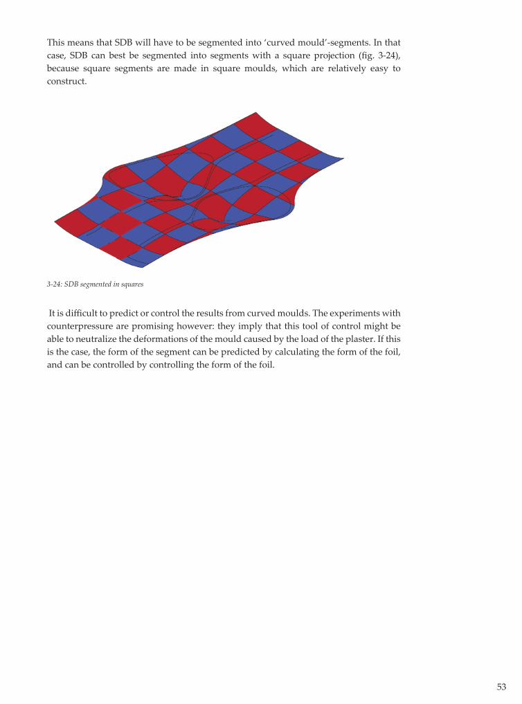
This means that SDB will have to be segmented into ‘curved mould’-segments. In that case, SDB can best be segmented into segments with a square projection (fi g. 3-24), because square segments are made in square moulds, which are relatively easy to construct.
3-24: SDB segmented in squares
It is diffi cult to predict or control the results from curved moulds. The experiments with counterpressure are promising however: they imply that this tool of control might be able to neutralize the deformations of the mould caused by the load of the plaster. If this is the case, the form of the segment can be predicted by calculating the form of the foil, and can be controlled by controlling the form of the foil.

54
3.5 Conclusions
In answer to the sub-question: ‘What forms can be built using fabric formwork segments, and what tools can be used to produce these forms?’
a number of experiments is analyzed and a list of tools of control is formulated. The experiments have led to the following conclusions:
- Fabform segments have a limited freedom of form.- Complex free forms can be constructed by assembling fabform segments to a complete form.- In the case of SDB, the segments have to be cast using curved moulds. The results of these moulds are harder to predict and control than those of fl at moulds. - In order to translate a segment design into a real segment, the aspects of form have to be controlled. The most promising tools of control for each aspect are: o Form class: edge shapes and counterpressure o Intensity of form: counterpressure o Thickness: countermould.
These tools of control will be subjected to additional research.
- Curved moulds can be controlled by counterpressure. There are indications that counterpressure neutralizes the deformation caused by the load of the plaster. This should be the subject of further research.

55


4. Design and Production of a Segment
58
4.1 Introduction
In the previous chapter, the general properties of fabform have been established. However, more specifi c research into moulds and tools of control is necessary. Also, the eff ects of scale and material need to be explored. This chapter describes the specifi c research of the design and the production of a segment.Unlike the previous chapter, the additional research in this chapter will focus on achieving a specifi c goal. This goal is formulated as the design of a segment. A number of experiments are conducted in order to determine in what way the design can be realized. Finally, a large mould is designed and built. This mould is used to produce three concrete segments. Based on this research and its results, an answer to following sub-question will be formulated:
‘In what way can the design of a free form-segment be realized using a fabric formwork?’
4.2 Design requirements of the segment
The ‘design’ of the segment consists of a collection of requirements the cast segment has to meet. These requirements follow from the construction, architectural- and structural design of a free form that is built using the prefab fabform system.
4.2.1 ConstructionThe segments will be utilized as a sacrifi cial formwork for the structural concrete that is cast at a later stage of the building process. Therefore, the segments should be able to resist the loads resulting from the pouring of the concrete. If a segment were to be reinforced traditionally by inserting a net of steel bars, this would introduce signifi cant problems in casting the panels. Such a net would have a complex form, which would make the steelfi xer’s job very diffi cult. It would be bett er to design a segment that can resist the loads applied to it without reinforcement.
4.2.2 Structural DesignAfter the structural concrete has been poured and cured, it is capable of bearing all of the loads working on the bridge. After the falsework is removed, the segments lose their structural purpose. Therefore, the segments need to be capable of resisting only the pouring loads. The stresses and strains in the segments result from the magnitude of the pouring load, the structure of the segment and the type of support by the falsework. The magnitude of the loads is derived from the geometry of the free form and cannot be altered by changing the design of the segment. The structure of the segment and its support however, can be. The strength and stiff ness of the segment depend on four factors: form, thickness, material and reinforcement. The form of the segment is determined by its architectural design. This leaves material, reinforcement and thickness to be determined.
Material and Reinforcement Since the late 1980’s the maximum compressive strength of concrete has developed rapidly. For instance, the maximum strength in 1985 was about 55 MPa, in 1990 about 85 MPA and since 1998, concrete with a strength of 200 MPa is available. Concrete with a
59
compressive strength between 150-200 MPa is called Ultra High Performance Concrete (UHPC). In this thesis, the term UHPC will be generally used for all high strength concretes. [5]UHPC is a suitable material for casting segments for a number of reasons:
- The high compressive (and tensile) strength of UHPC off ers the opportunity of casting very light and thin structures. It also allows omitt ing the traditional steel reinforcement or replacing it with steel- or synthetic fi bers. Next to avoiding the production and application of a complex reinforcement net, this also allows the segments to be thinner. Traditional reinforcement requires a minimum concrete cover, forcing the minimum thickness of a segment to what is perhaps a higher value then structurally necessary. - The density of UHPC is much higher than that of regular concrete. This makes UHPC very durable, as it has much less pores for aggressive substances to penetrate. For the same reason, it is less easily polluted and easier to clean than regular concrete. - UHPC provides a stunning surface quality, which mirrors the surface of its formwork in great detail.- Regular concrete has to be consolidated after pouring, to make sure any air bubbles disappear from it. This is often done by using a concrete vibrator. This device cannot be used on a vulnerable fabric surface though. UHPC is a self-consolidating concrete, so it does not need to be treated with a concrete vibrator. - UHPC has a low consistency, making it possible to ‘push’ the concrete from its natural state -a puddle at the lowest point of a mould- to higher points of the mould. The only downside to the use of UHPC is its price, which is 20 to 30 times the price of regular concrete anno 2010. Therefore, the concrete has to be used as effi cient as possible.
ThicknessWhen the thickness is not determined by the reinforcement and its cover on both sides, it is only determined by the required structural height necessary to resist the performing stresses in the segment. These stresses can be lowered by the type of support of the segment though. Therefore, the only real factors in determining the thickness of the segment are the minimum structural height necessary for handling the segments and the properties of the mould that is going to be used to cast these segments.If the segments have a minimum thickness, the most UHPC is saved if the entire segment is of the same thickness. This would mean that the segments would be of a uniform thickness, being its minimum thickness.
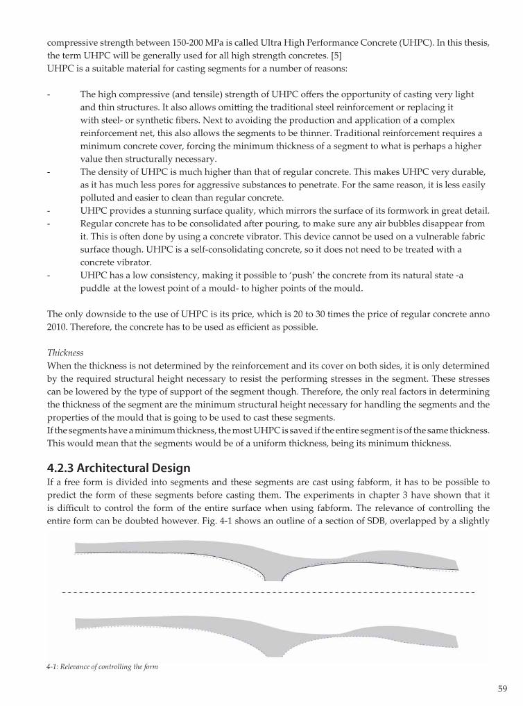
4.2.3 Architectural DesignIf a free form is divided into segments and these segments are cast using fabform, it has to be possible to predict the form of these segments before casting them. The experiments in chapter 3 have shown that it is diffi cult to control the form of the entire surface when using fabform. The relevance of controlling the entire form can be doubted however. Fig. 4-1 shows an outline of a section of SDB, overlapped by a slightly
4-1: Relevance of controlling the form
60
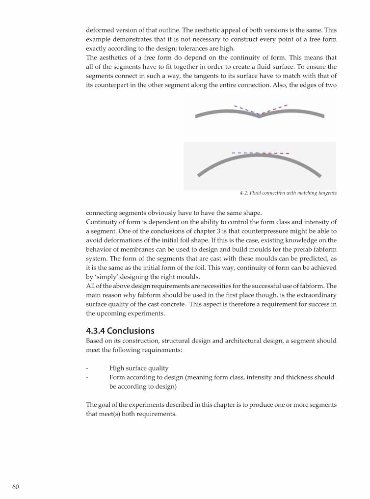
deformed version of that outline. The aesthetic appeal of both versions is the same. This example demonstrates that it is not necessary to construct every point of a free form exactly according to the design; tolerances are high. The aesthetics of a free form do depend on the continuity of form. This means that all of the segments have to fi t together in order to create a fl uid surface. To ensure the segments connect in such a way, the tangents to its surface have to match with that of its counterpart in the other segment along the entire connection. Also, the edges of two
4-2: Fluid connection with matching tangents
connecting segments obviously have to have the same shape. Continuity of form is dependent on the ability to control the form class and intensity of a segment. One of the conclusions of chapter 3 is that counterpressure might be able to avoid deformations of the initial foil shape. If this is the case, existing knowledge on the behavior of membranes can be used to design and build moulds for the prefab fabform system. The form of the segments that are cast with these moulds can be predicted, as it is the same as the initial form of the foil. This way, continuity of form can be achieved by ‘simply’ designing the right moulds.All of the above design requirements are necessities for the successful use of fabform. The main reason why fabform should be used in the fi rst place though, is the extraordinary surface quality of the cast concrete. This aspect is therefore a requirement for success in the upcoming experiments.
4.3.4 ConclusionsBased on its construction, structural design and architectural design, a segment should meet the following requirements:
- High surface quality - Form according to design (meaning form class, intensity and thickness should be according to design)
The goal of the experiments described in this chapter is to produce one or more segments that meet(s) both requirements.
61
4.3 Experimental study of free-form segments using fabric formwork
4.3.1 IntroductionThe experiments that have been conducted so far have been on a small scale. Also, all of the cast samples have been made out of plaster. The eff ect of scale and material on the end result can obviously not be ignored. Therefore a larger, concrete segment will be produced. However, constructing a large mould will require a large investment in time and material. For practical reasons, only one mould can be made, which implies there is no chance to experiment with diff erent types of large moulds. Therefore, some additional small-scale experiments with the various tools of manipulation will be conducted fi rst, to be able to determine the best design for a large mould. Because the surface quality was already excellent in earlier experiments, no att empts are made to research this aspect any further. The leaves the continuity of form and thickness to be researched.
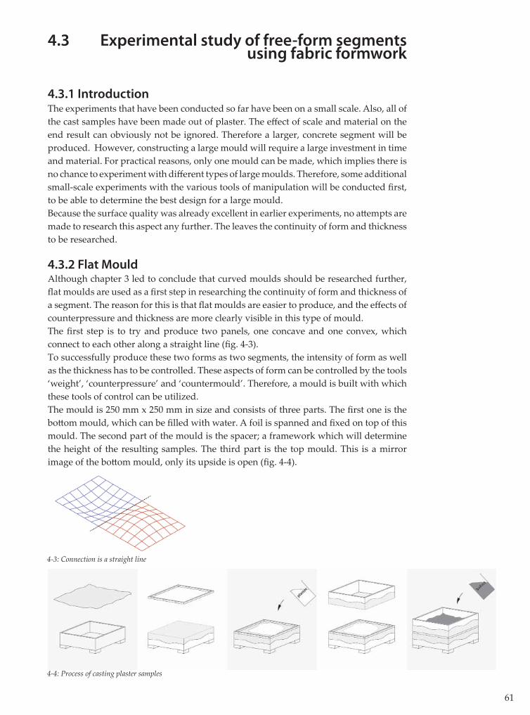
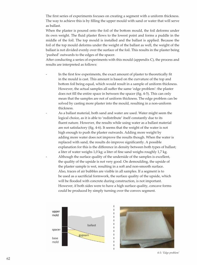
4.3.2 Flat MouldAlthough chapter 3 led to conclude that curved moulds should be researched further, fl at moulds are used as a fi rst step in researching the continuity of form and thickness of a segment. The reason for this is that fl at moulds are easier to produce, and the eff ects of counterpressure and thickness are more clearly visible in this type of mould.The fi rst step is to try and produce two panels, one concave and one convex, which connect to each other along a straight line (fi g. 4-3).To successfully produce these two forms as two segments, the intensity of form as well as the thickness has to be controlled. These aspects of form can be controlled by the tools ‘weight’, ‘counterpressure’ and ‘countermould’. Therefore, a mould is built with which these tools of control can be utilized. The mould is 250 mm x 250 mm in size and consists of three parts. The fi rst one is the bott om mould, which can be fi lled with water. A foil is spanned and fi xed on top of this mould. The second part of the mould is the spacer; a framework which will determine the height of the resulting samples. The third part is the top mould. This is a mirror image of the bott om mould, only its upside is open (fi g. 4-4).
4-3: Connection is a straight line
4-4: Process of casting plaster samples
62
The fi rst series of experiments focuses on creating a segment with a uniform thickness. The way to achieve this is by fi lling the upper mould with sand or water that will serve as ballast.When the plaster is poured onto the foil of the bott om mould, the foil deforms under its own weight. The fl uid plaster fl ows to the lowest point and forms a puddle in the middle of the foil. The top mould is installed and the ballast is applied. Because the foil of the top mould deforms under the weight of the ballast as well, the weight of the ballast is not divided evenly over the surface of the foil. This results in the plaster being ‘pushed’ outwards to the edges of the spacer. After conducting a series of experiments with this mould (appendix C), the process and results are interpreted as follows:
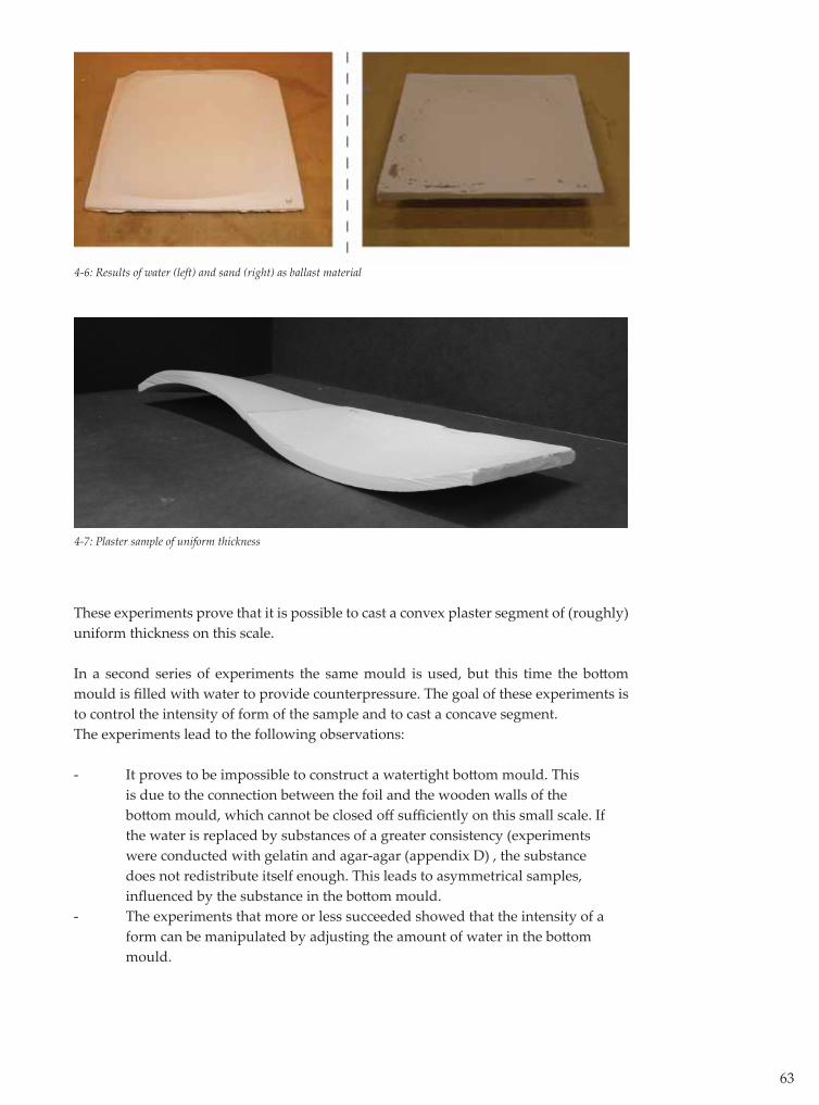
- In the fi rst few experiments, the exact amount of plaster to theoretically fi t in the mould is cast. This amount is based on the curvature of the top and bott om foil being equal, which would result in a sample of uniform thickness. However, the actual samples all suff er the same ‘edge problem’: the plaster does not fi ll the entire space in between the spacer (fi g. 4-5). This can only mean that the samples are not of uniform thickness. The edge problem can be solved by casting more plaster into the mould, resulting in a non-uniform thickness.- As a ballast material, both sand and water are used. Water might seem the logical choice, as it is able to ‘redistribute’ itself constantly due to its fl uent nature. However, the results while using water as a ballast material are not satisfactory (fi g. 4-6). It seems that the weight of the water is not high enough to push the plaster outwards. Adding more weight by adding more water does not improve the results though. When the water is replaced with sand, the results do improve signifi cantly. A possible explanation for this is the diff erence in density between both types of ballast; a liter of water weighs 1,0 kg; a liter of fi ne sand weighs roughly 1,7 kg. - Although the surface quality of the underside of the samples is excellent, the quality of the upside is not very good. On demoulding, the upside of the plaster sample is wet, resulting in a soft and non-smooth surface. Also, traces of air bubbles are visible in all samples. If a segment is to be used as a sacrifi cial formwork, the surface quality of the upside, which will be fl ooded with concrete during construction, is not important. However, if both sides were to have a high surface quality, concave forms could be produced by simply turning over the convex segment.
4-5: ‘Edge problem’
63
These experiments prove that it is possible to cast a convex plaster segment of (roughly) uniform thickness on this scale.
In a second series of experiments the same mould is used, but this time the bott om mould is fi lled with water to provide counterpressure. The goal of these experiments is to control the intensity of form of the sample and to cast a concave segment.The experiments lead to the following observations:
- It proves to be impossible to construct a watertight bott om mould. This is due to the connection between the foil and the wooden walls of the bott om mould, which cannot be closed off suffi ciently on this small scale. If the water is replaced by substances of a greater consistency (experiments were conducted with gelatin and agar-agar (appendix D) , the substance does not redistribute itself enough. This leads to asymmetrical samples, infl uenced by the substance in the bott om mould. - The experiments that more or less succeeded showed that the intensity of a form can be manipulated by adjusting the amount of water in the bott om mould.
4-6: Results of water (left) and sand (right) as ballast material
4-7: Plaster sample of uniform thickness
64
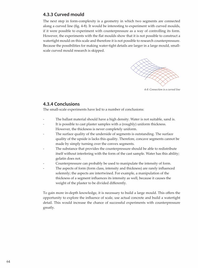
4.3.3 Curved mould
The next step in form-complexity is a geometry in which two segments are connected along a curved line (fi g. 4-8). It would be interesting to experiment with curved moulds, if it were possible to experiment with counterpressure as a way of controlling its form. However, the experiments with the fl at moulds show that it is not possible to construct a watertight mould on this scale and therefore it is not possible to research counterpressure. Because the possibilities for making water-tight details are larger in a large mould, small-scale curved mould research is skipped.
4.3.4 ConclusionsThe small-scale experiments have led to a number of conclusions:
- The ballast material should have a high density. Water is not suitable, sand is.- It is possible to cast plaster samples with a (roughly) uniform thickness. However, the thickness is never completely uniform. - The surface quality of the underside of segments is outstanding. The surface quality of the upside is lacks this quality. Therefore, concave segments cannot be made by simply turning over the convex segments.- The substance that provides the counterpressure should be able to redistribute itself without interfering with the form of the cast sample. Water has this ability; gelatin does not.- Counterpressure can probably be used to manipulate the intensity of form.- The aspects of form (form class, intensity and thickness) are rarely infl uenced solemnly; the aspects are intertwined. For example, a manipulation of the thickness of a segment infl uences its intensity as well, because it causes the weight of the plaster to be divided diff erently.
To gain more in-depth knowledge, it is necessary to build a large mould. This off ers the opportunity to explore the infl uence of scale, use actual concrete and build a watertight detail. This would increase the chance of successful experiments with counterpressure greatly.
4-8: Connection is a curved line
65
4.4 Design and construction of the large mould
4.4.1 Introduction The large mould is built in order to explore the eff ects of scale and material as well as the eff ects of counter pressure and weight. The mould is ten times the size of the small-scale moulds and suitable for casting concrete instead of plaster. The bott om mould will be watertight and the top mould will be suitable for using sand as an additional load.
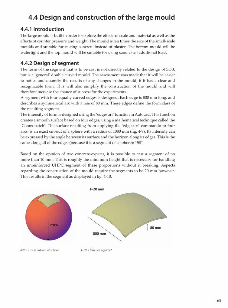
4.4.2 Design of segmentThe form of the segment that is to be cast is not directly related to the design of SDB, but is a ‘general’ double curved mould. The assessment was made that it will be easier to notice and quantify the results of any changes in the mould, if it has a clear and recognizable form. This will also simplify the construction of the mould and will therefore increase the chance of success for the experiments.A segment with four equally curved edges is designed. Each edge is 800 mm long, and describes a symmetrical arc with a rise of 80 mm. These edges defi ne the form class of the resulting segment.The intensity of form is designed using the ‘edgesurf’ function in Autocad. This function creates a smooth surface based on four edges, using a mathematical technique called the ‘Coons patch’. The surface resulting from applying the ‘edgesurf’-commando to four arcs, is an exact cut-out of a sphere with a radius of 1080 mm (fi g. 4-9). Its intensity can be expressed by the angle between its surface and the horizon along its edges. This is the same along all of the edges (because it is a segment of a sphere): 158°.
Based on the opinion of two concrete-experts, it is possible to cast a segment of no more than 10 mm. This is roughly the minimum height that is necessary for handling an unreinforced UHPC segment of these proportions without it breaking. Aspects regarding the construction of the mould require the segments to be 20 mm however. This results in the segment as displayed in fi g. 4-10.
4-9: Form is cut-out of sphere 4-10: Designed segment
66
4.4.3 Design of the mould
The mould consists of a bott om mould, a spacer and a top mould, like the mould in §4.3. The principle of the mould is basically the same as explained in fi g. 4.4.The bott om mould has to provide the counter-pressure for the concrete. Therefore, it will be fi lled with only water; the air will have to be removed entirely. This demands a water- and airtight connection between the mould and the foil that is stretched over it. Because the edges of the mould are curved, this requires a specifi c solution. The spacer is placed on top of the bott om mould. It determines the thickness of the edges of the segment, and subsequently the distance between the bott om and top mould. The edges of the spacer should be curved in the exact same shape as the bott om mould, so it will fi t on top of it.The top mould serves as the ‘lid on the jar’; it completes the mould. The top mould consists of a layer of foil that is fi xed to a wooden framework. The edges of the framework are curved to fi t exactly on top of the spacer. The top mould will be fi lled up with sand, so the connection between the wood and foil should be able to stop the sand from spilling (fi g. 4-11).
The biggest challenge in designing the mould is to create a detail that ensures for the bott om mould to be water- and airtight, while still allowing the three parts of the mould to be disassembled easily. To solve this problem, a detail was designed based on clamping the foil and a rubber cord between the bott om mould and spacer. The rubber cord is partially ‘buried’ in a groove that is milled into the edges of the mould (fi g. 4-12).
To make this detail function properly, the rubber cord has to be pressed to deform, clamping the foil in between the two wooden moulds. This achieve this, a steel frame is att ached around both the bott om mould and the spacer. A number of threaded steel rods are att ached to the steel frame of the bott om mould, and sticked through holes in the steel frame of the spacer. Subsequently, the spacer is pulled down onto the bott om mould, by tightening wing nuts onto the rods. By doing so, the two parts of the mould are clamped together, creating a watertight connection between foil and mould. This detail is used in the top mould as well.
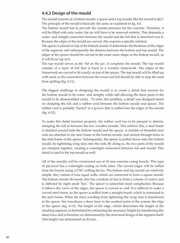
All of the moulds will be constructed out of 18 mm concrete casing boards. This type of plywood has a watertight coating on both sides. The curved edges will be milled from the boards using a CNC-milling device. The bott om and top mould are relatively simple; they consist of four equal walls, which are connected to form a square mould. The bott om mould obviously also has a bott om (it has to hold a volume of water) and is stiff ened by eight small ‘fi ns’. The spacer is somewhat more complicated. Because it follows the curve of the edges, the spacer is curved as well. It is diffi cult to make a curved steel frame, so the spacer is milled from a straight board, which is connected to the steel frame. When the force resulting from tightening the wing nuts is transferred to the spacer, this introduces a shear force in the weakest point of the system: the edge of the spacer (fi g. 4-13). The height of the edge, which determines the height of the resulting segment, is determined by estimating the necessary height for transferring this shear force and is therefore not determined by the structural design of the segment itself. This height was determined on 20 mm.

67
4-11: Exploded view of the mould
4-12: Mould detail 4-13: Shear force in spacer edge
4-14: Process of casting concrete segments
Rubber cord

68
The fabric of choice has to meet a number of requirements:
- The fabric is required to have a high elasticity, allowing any wrinkles in the foil to be ‘stretched out’ of it.- The fabric should be strong enough to resist the stresses resulting from pretension, the casting of the concrete and the applying of the ballast. However, the counter pressure of the water should support a signifi cant part of these loads, decreasing the stresses in the fabric greatly. - The fabric should be available in dimensions larger than 800 x 800 mm, to avoid seams within the mould. - The fabric should be water-tight.
There are a number of fabrics that meet these requirements. For this mould, ETFE-foil was chosen, turning the ‘fabric formwork’ into a ‘foil formwork’. This material is increasingly used in the building industry because of its good mechanical, chemical and thermal properties. The transparent foil is very smooth, so the surface of the resulting concrete is expected to be smooth as well. The foil will be spanned onto the mould by simple taping it to its edges. After the spacer is clamped to the bott om mould, the foil will no longer be supported by the tape, but by the clamped connection. If the bott om mould is to be fi lled with water, there must be a way to remove the air from the mould. To do so, four holes are drilled through the walls of the mould. Air can escape through four tubes that will be stuck through these holes and end at the highest points within the mould. Also, a tub is to be connected to the bott om mould. The tub can be fi lled with water to allow water to fl ow into the mould through a hose. The hose can be closed off with a tap.
4.4.4 Construction of the mouldThe mould was built according to the previously described design. An important aspect in the construction is the accuracy of the parts of the mould. If the edges of the bott om mould do not match the edges of the spacer exactly, the connection will not be water- and airtight. Deviations were prevented by milling all of the curved edges with a CNC-milling device (fi g. 4-15). Also, small beads are inserted in each edge connection between the wooden boards (fi g. 4-16). This prevents the connections between the boards to shift in height.
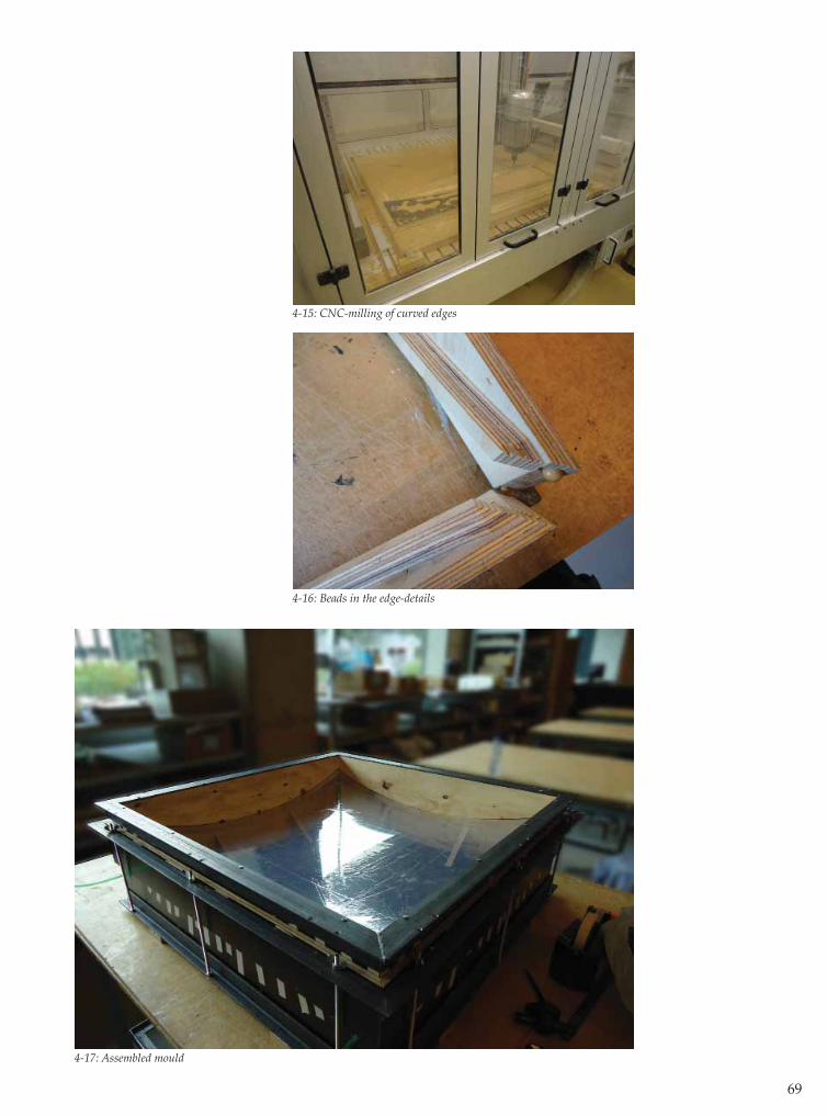
69
4-15: CNC-milling of curved edges
4-16: Beads in the edge-details
4-17: Assembled mould

70
4.5 Experiments with the large mould
4.5.1 IntroductionThree experiments are conducted using the large moulds, resulting in three concrete segments. To make these segments easy to distinguish, all three are cast in a diff erent color concrete: beige, black and grey. The goal of the experiments is to answer a number of questions, which follow from the two requirements in §4.3.4:
Surface quality- How is the quality of the surface of both sides of the segments?
This question will be answered based on a visual inspection of the segments. The smoothness, texture and color of the segments will be regarded.
Form- Can the form class and intensity of the designed form be realized in the form of an actual concrete segment?
To answer this question, the form of the concrete segment has to be determined, so it can be processed to a 3D-CAD model. This model can be compared to the 3D-model of the designed segment.
- Is it possible to manipulate the intensity of the form of the segment by adjusting the amount of water in the mould?
This question can be answered by comparing the intensity of two segments, cast in a mould with diff erent amounts of water.
- Is it possible to create a segment with a uniform thickness?
Wether or not a segment is of uniform thickness or not, can be determined by casting the amount of concrete that corresponds to a segment of uniform thickness. If the segment is not of uniform thickness, the thickness at the edges will be less than 20 mm. To answer the question, both sides of a segment should be measured. This way, the thickness can be determined along its sections.

71
4.5.2 Production process segment
The process of casting a segment consists of 9 steps, as schematically displayed in fi g. 4-18. Depending on the desired properties of the segments and the state of the mould, the fi rst fi ve steps can be omitt ed when conducting the second and third experiment.
1. Before the casting process commences, the tub is placed on a higher surface than the bott om mould. The spacer is fi xed onto the bott om mould by tightening the wing nuts. The tub is fi lled with water and the starting volume is registered. The bott om mould is empty. By opening the tap between the tub and mould, water fl ows into the mould (in accordance with the law of interconnected vessels). Air is allowed to bleed through the four tubes. 2. When all of the air has bled from the mould, water will start pouring out of the tubes. At this point, the tubes are shut off and the tap is closed.3. The tub is moved to a surface which is lower than the surface on which the mould is placed. By opening the tap, water from the mould will fl ow back into the tub. Because there is no air in the mould, the foil will be pulled down with the water.4. By determining the volume of water in the tub, it is possible to calculate the volume of water in the bott om mould. When the desired volume is reached, the tap is closed.
5. Concrete is poured on top of the foil.6. The top mould is spanned onto the middle part of the mould using the wing nuts.7. Sand is shoveled into the top mould, serving as ballast. The concrete is left to cure for some time (depending on the concrete mixture and desired strength at demoulding)
8. After the concrete is cured, the sand is removed from the top mould, followed by the removal of the top mould itself. The tub is placed on the high surface again, and the tap is opened to allow water to fl ow into the mould. The water pressure causes the segment to ascend.9. After the segment has ascended enough to grab its edges, the tap is closed again. The segment can now be lifted from the mould.
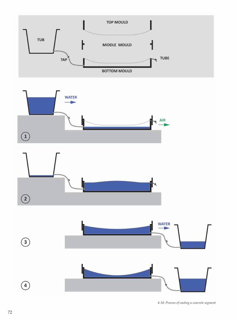
72
4-18: Process of casting a concrete segment

73

74
4.5.3 Experiments
Beige Segment
The goal of the fi rst experiment is to determine whether or not it is possible to produce a segment of uniform thickness in the large mould. This research will be conducted by fi lling the mould with the theoretical volume of concrete for a segment of 20 mm thick. The volume of concrete to pour is 12,8 liters, which is derived from the CAD-model. The volume of water in the bott om mould is also derived from this model (based on the spherical segment) and is set to 47 l. The beige concrete mixture will be comparable to a C80/95 concrete class after 28 days of curing. The maximum grain diameter in the mixture is 2 mm. No fi bers were added. The mould will be fi lled with sand. The volume of the sand will be determined during the experiment.
All the air has bled from the mould when after it is fi lled with 84 l. of water. The water is allowed to fl ow back out of the mould (after the bleeding-tubes are closed) causing 30 liters of water to fl ow back out of the mold. It is not possible to drain any more water out of the mould, leaving the bott om mould fi lled with 54 liters instead of 47 liters of water. After the bott om mould is fi lled with water, the wooden edges are treated with a wax to prevent them from sticking to the concrete when demoulding. The concrete is mixed and roughly 13 liters of the batch is poured into the middle of the foil. The concrete forms a puddle in the middle of the foil. The top mould is installed and tightened onto the bott om mould using the wing-nuts, after which it is fi lled with sand. The sand is pressed together, causing the concrete to spread to the edges of the mould. The concrete reaches the lower edges of the mould, but it does not reach the four corners, regardless of the pressure that is applied on top of the sand. The entire process, from fi lling the bott om mould with water to preparing and applying the concrete until applying the sand, takes about an hour and a half.
After 20 hours, the segment is demoulded. Because the corners of the mould are not fi lled with concrete, it is possible to grab a hold of the concrete segment in these corners. The concrete does not adhere to the foil and wooden edges at all, making the demoulding a simple task. The bott om mould has a small volume of air in it, concentrated in the corners. The bott om foil is still stretched in the desired form though.
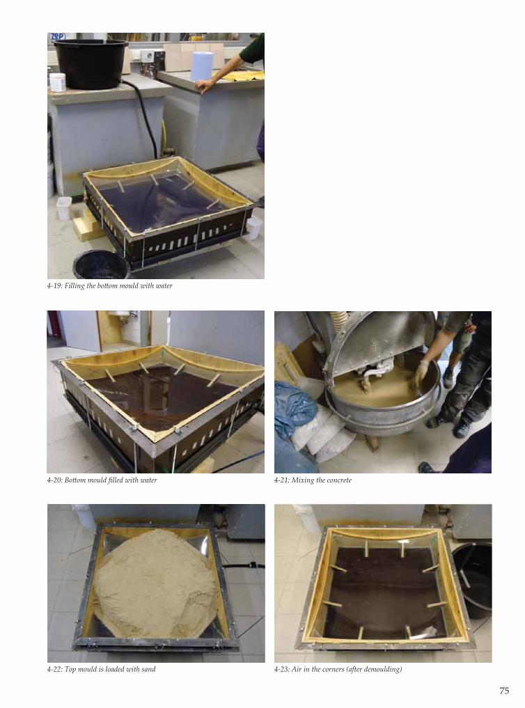
75
4-19: Filling the bott om mould with water
4-20: Bott om mould fi lled with water 4-21: Mixing the concrete
4-22: Top mould is loaded with sand 4-23: Air in the corners (after demoulding)
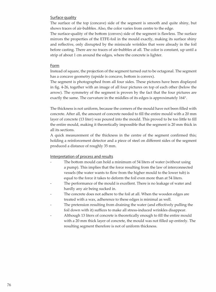
76
Surface qualityThe surface of the top (concave) side of the segment is smooth and quite shiny, but shows traces of air-bubbles. Also, the color varies from centre to the edge.The surface-quality of the bott om (convex) side of the segment is fl awless. The surface mirrors the properties of the ETFE-foil in the mould exactly, making its surface shiny and refl ective, only disrupted by the miniscule wrinkles that were already in the foil before casting. There are no traces of air-bubbles at all. The color is constant, up until a strip of about 1 cm around the edges, where the concrete is lighter.
FormInstead of square, the projection of the segment turned out to be octagonal. The segment has a concave geometry (upside is concave, bott om is convex).The segment is photographed from all four sides. These pictures have been displayed in fi g. 4-26, together with an image of all four pictures on top of each other (below the arrow). The symmetry of the segment is proven by the fact that the four pictures are exactly the same. The curvature in the middles of its edges is approximately 164°.
The thickness is not uniform, because the corners of the mould have not been fi lled with concrete. After all, the amount of concrete needed to fi ll the entire mould with a 20 mm layer of concrete (13 liter) was poured into the mould. This proved to be too litt le to fi ll the entire mould, making it theoretically impossible that the segment is 20 mm thick in all its sections.A quick measurement of the thickness in the centre of the segment confi rmed this; holding a reinforcement detector and a piece of steel on diff erent sides of the segment produced a distance of roughly 35 mm.
Interpretation of process and results- The bott om mould can hold a minimum of 54 liters of water (without using a pump). This implies that the force resulting from the law of interconnected vessels (the water wants to fl ow from the higher mould to the lower tub) is equal to the force it takes to deform the foil even more than at 54 liters. - The performance of the mould is excellent. There is no leakage of water and hardly any air being sucked in.- The concrete does not adhere to the foil at all. When the wooden edges are treated with a wax, adherence to these edges is minimal as well.- The pretension resulting from draining the water (and eff ectively pulling the foil down with it) suffi ces to make all stress-induced wrinkles disappear. - Although 13 liters of concrete is theoretically enough to fi ll the entire mould with a 20 mm thick layer of concrete, the mould was not fi lled up entirely. The resulting segment therefore is not of uniform thickness.
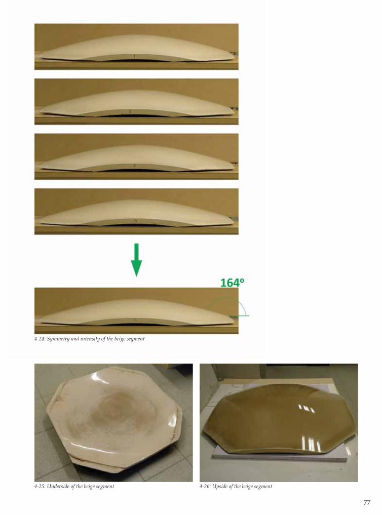
77
4-24: Symmetry and intensity of the beige segment
4-25: Underside of the beige segment 4-26: Upside of the beige segment
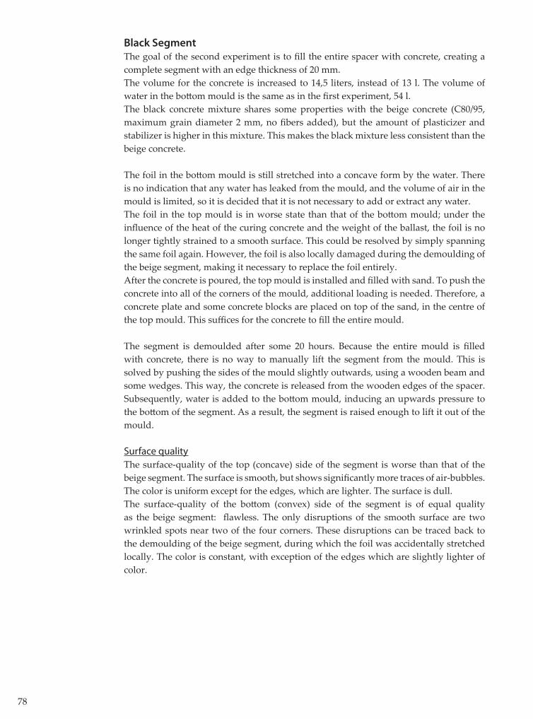
78
Black Segment
The goal of the second experiment is to fi ll the entire spacer with concrete, creating a complete segment with an edge thickness of 20 mm. The volume for the concrete is increased to 14,5 liters, instead of 13 l. The volume of water in the bott om mould is the same as in the fi rst experiment, 54 l.The black concrete mixture shares some properties with the beige concrete (C80/95, maximum grain diameter 2 mm, no fi bers added), but the amount of plasticizer and stabilizer is higher in this mixture. This makes the black mixture less consistent than the beige concrete.
The foil in the bott om mould is still stretched into a concave form by the water. There is no indication that any water has leaked from the mould, and the volume of air in the mould is limited, so it is decided that it is not necessary to add or extract any water. The foil in the top mould is in worse state than that of the bott om mould; under the infl uence of the heat of the curing concrete and the weight of the ballast, the foil is no longer tightly strained to a smooth surface. This could be resolved by simply spanning the same foil again. However, the foil is also locally damaged during the demoulding of the beige segment, making it necessary to replace the foil entirely.After the concrete is poured, the top mould is installed and fi lled with sand. To push the concrete into all of the corners of the mould, additional loading is needed. Therefore, a concrete plate and some concrete blocks are placed on top of the sand, in the centre of the top mould. This suffi ces for the concrete to fi ll the entire mould.
The segment is demoulded after some 20 hours. Because the entire mould is fi lled with concrete, there is no way to manually lift the segment from the mould. This is solved by pushing the sides of the mould slightly outwards, using a wooden beam and some wedges. This way, the concrete is released from the wooden edges of the spacer. Subsequently, water is added to the bott om mould, inducing an upwards pressure to the bott om of the segment. As a result, the segment is raised enough to lift it out of the mould.
Surface qualityThe surface-quality of the top (concave) side of the segment is worse than that of the beige segment. The surface is smooth, but shows signifi cantly more traces of air-bubbles. The color is uniform except for the edges, which are lighter. The surface is dull.The surface-quality of the bott om (convex) side of the segment is of equal quality as the beige segment: fl awless. The only disruptions of the smooth surface are two wrinkled spots near two of the four corners. These disruptions can be traced back to the demoulding of the beige segment, during which the foil was accidentally stretched locally. The color is constant, with exception of the edges which are slightly lighter of color.

79
4-27: Wet concrete poured on bott om foil 4-28: Additional ballast
4-29: Upside of the black segment at demoulding 4-30: Underside of the black segment
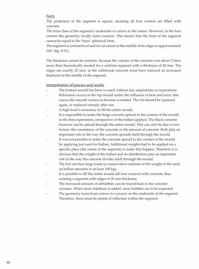
80
FormThe projection of the segment is square, meaning all four corners are fi lled with concrete.The form class of the segment’s underside is convex in the centre. However, in the four corners the geometry locally turns concave. This means that the form of the segment cannot be equal to the ‘basic’ spherical form.The segment is symmetrical and its curvature in the middle of its edges is approximately 164° (fi g. 4-31).
The thickness cannot be uniform, because the volume of the concrete was about 2 liters more than theoretically needed for a uniform segment with a thickness of 20 mm. The edges are exactly 20 mm, so the additional concrete must have induced an increased thickness in the middle of the segment.
Interpretation of process and results- The bott om mould has been re-used without any adaptations or reparations.- Relaxation occurs in the top mould under the infl uence of heat and force; this causes the smooth surface to become wrinkled. The foil should be spanned again, or replaced entirely after use.- A high load is necessary to fi ll the entire mould. - It is impossible to make the beige concrete spread to the corners of the mould in the fi rst experiment, irrespective of the ballast applied. The black concrete however can be spread through the entire mould. This can only be due to two factors: the consistency of the concrete or the amount of concrete. Both play an important role in the way the concrete spreads itself through the mould.- It was not possible to make the concrete spread to the corners of the mould by applying just sand for ballast. Additional weights had to be applied on a specifi c place (the centre of the segment) to make this happen. Therefore it is obvious that the weight of the ballast and its distribution play an important role in the way the concrete divides itself through the mould. - The foil can bear large loads (a conservative estimate of the weight of the sand an ballast amounts to at least 100 kg). - It is possible to fi ll the entire mould (all four corners) with concrete; thus creating a segment with edges of 20 mm thickness.- The increased amount of airbubbles can be traced back to the concrete mixture. When more stabilizer is added, more bubbles are to be expected.- The geometry turns from convex to concave on the underside of the segment. Therefore, there must be points of infl ection within the segment.

81
4-31: Symmetry and intensity of the black segment
4-32: Black segment from the side 4-33: Detail of the black segment
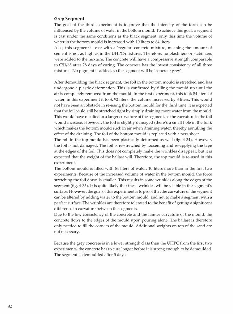
82
Grey Segment
The goal of the third experiment is to prove that the intensity of the form can be infl uenced by the volume of water in the bott om mould. To achieve this goal, a segment is cast under the same conditions as the black segment, only this time the volume of water in the bott om mould is increased with 10 liters to 64 liters.Also, this segment is cast with a ‘regular’ concrete mixture, meaning the amount of cement is not as high as in the UHPC-mixtures. Therefore, no plastifi ers or stabilizers were added to the mixture. The concrete will have a compressive strength comparable to C53/65 after 28 days of curing. The concrete has the lowest consistency of all three mixtures. No pigment is added, so the segment will be ‘concrete-grey’. After demoulding the black segment, the foil in the bott om mould is stretched and has undergone a plastic deformation. This is confi rmed by fi lling the mould up until the air is completely removed from the mould. In the fi rst experiment, this took 84 liters of water; in this experiment it took 92 liters: the volume increased by 8 liters. This would not have been an obstacle in re-using the bott om mould for the third time; it is expected that the foil could still be stretched tight by simply draining more water from the mould. This would have resulted in a larger curvature of the segment, as the curvature in the foil would increase. However, the foil is slightly damaged (there’s a small hole in the foil), which makes the bott om mould suck in air when draining water, thereby annulling the eff ect of the draining. The foil of the bott om mould is replaced with a new sheet.The foil in the top mould has been plastically deformed as well (fi g. 4-34). However, the foil is not damaged. The foil is re-stretched by loosening and re-applying the tape at the edges of the foil. This does not completely make the wrinkles disappear, but it is expected that the weight of the ballast will. Therefore, the top mould is re-used in this experiment.The bott om mould is fi lled with 64 liters of water, 10 liters more than in the fi rst two experiments. Because of the increased volume of water in the bott om mould, the force stretching the foil down is smaller. This results in some wrinkles along the edges of the segment (fi g. 4-35). It is quite likely that these wrinkles will be visible in the segment’s surface. However, the goal of this experiment is to proof that the curvature of the segment can be altered by adding water to the bott om mould, and not to make a segment with a perfect surface. The wrinkles are therefore tolerated to the benefi t of gett ing a signifi cant diff erence in curvature between the segments.Due to the low consistency of the concrete and the fainter curvature of the mould; the concrete fl ows to the edges of the mould upon pouring alone. The ballast is therefore only needed to fi ll the corners of the mould. Additional weights on top of the sand are not necessary.
Because the grey concrete is in a lower strength class than the UHPC from the fi rst two experiments, the concrete has to cure longer before it is strong enough to be demoulded. The segment is demoulded after 5 days.
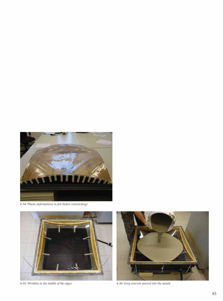
83
4-34: Plastic deformations in foil (before restretching)
4-35: Wrinkles in the middle of the edges 4-36: Grey concrete poured into the mould
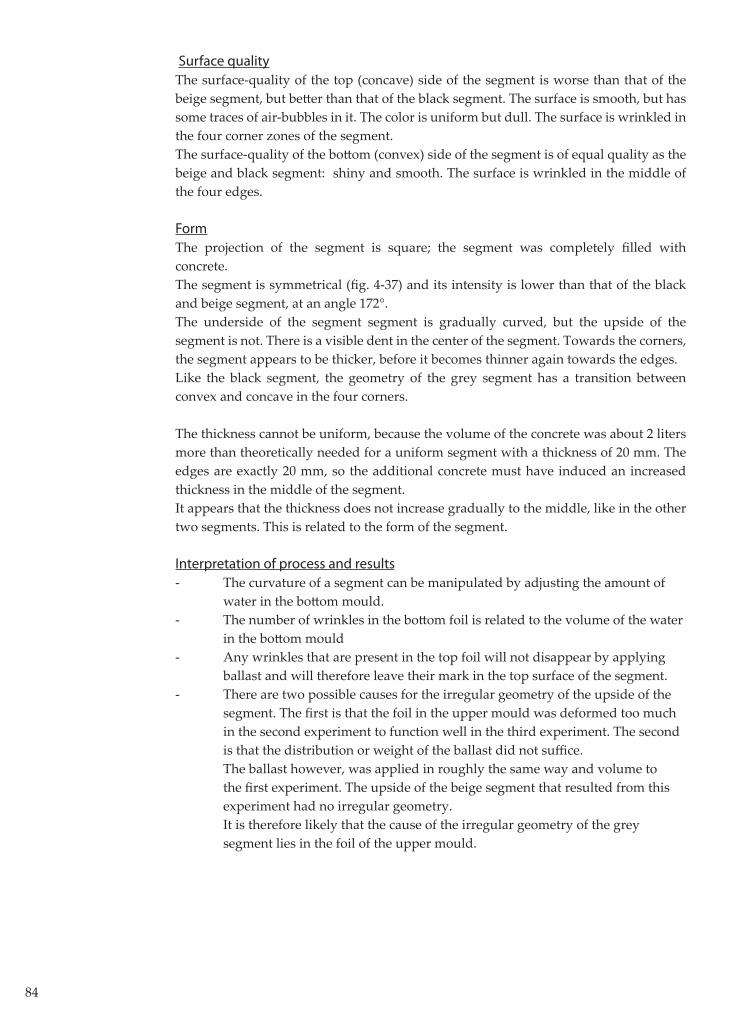
84
Surface qualityThe surface-quality of the top (concave) side of the segment is worse than that of the beige segment, but bett er than that of the black segment. The surface is smooth, but has some traces of air-bubbles in it. The color is uniform but dull. The surface is wrinkled in the four corner zones of the segment.The surface-quality of the bott om (convex) side of the segment is of equal quality as the beige and black segment: shiny and smooth. The surface is wrinkled in the middle of the four edges.
FormThe projection of the segment is square; the segment was completely fi lled with concrete. The segment is symmetrical (fi g. 4-37) and its intensity is lower than that of the black and beige segment, at an angle 172°.The underside of the segment segment is gradually curved, but the upside of the segment is not. There is a visible dent in the center of the segment. Towards the corners, the segment appears to be thicker, before it becomes thinner again towards the edges. Like the black segment, the geometry of the grey segment has a transition between convex and concave in the four corners.
The thickness cannot be uniform, because the volume of the concrete was about 2 liters more than theoretically needed for a uniform segment with a thickness of 20 mm. The edges are exactly 20 mm, so the additional concrete must have induced an increased thickness in the middle of the segment. It appears that the thickness does not increase gradually to the middle, like in the other two segments. This is related to the form of the segment.
Interpretation of process and results- The curvature of a segment can be manipulated by adjusting the amount of water in the bott om mould.- The number of wrinkles in the bott om foil is related to the volume of the water in the bott om mould- Any wrinkles that are present in the top foil will not disappear by applying ballast and will therefore leave their mark in the top surface of the segment. - There are two possible causes for the irregular geometry of the upside of the segment. The fi rst is that the foil in the upper mould was deformed too much in the second experiment to function well in the third experiment. The second is that the distribution or weight of the ballast did not suffi ce. The ballast however, was applied in roughly the same way and volume to the fi rst experiment. The upside of the beige segment that resulted from this experiment had no irregular geometry. It is therefore likely that the cause of the irregular geometry of the grey segment lies in the foil of the upper mould.
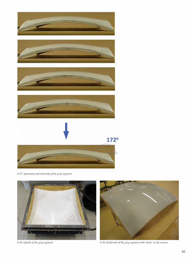
85
4-37: Symmetry and intensity of the grey segment
4-38: Upside of the grey segment 4-39: Underside of the grey segment with ‘dents’ in the corners

86
4.5.4 Measuring a segment
The visual inspections of the segments provide limited information about their actual form. Therefore, the form of the up- and underside of the black sample is measured. The goal of measuring the form is to obtain a 3D-CAD model of the segment which can be used to compare the segment to the designed form and to gain insight in the real thickness of the segment along its sections.Because the segment is symmetrical, only 1/8th of the surface has to be measured. If the segment is placed in a (virtual) 3D Carthesian system of coordinates, its z-coordinates can be measured on a number fi xed points. Because the x- and y-coordinates are known, the z-coordinate determines a point on the surface of the segment. If all of these points are connected and mirrored, a 3D-model of the segment can be drawn [app. E].To be able to measure the z-coordinates, a ‘table’ is built, which can be set up over the segment (fi g. 4-40). Holes have been drilled through the tabletop. If a steel rod is inserted through one of these holes, it will eventually hit the surface of the segment. When the distance from the end of the steel rod (on the surface of the segment) to the tabletop is measured, the z-coordinate of the segment can be calculated. The coordinates of 70 points, divided over 1/8th of the segment are measured on both the upside and underside of the segment. Based on these points, a 3D-model is drawn.
Regarding the information from the 3D-model, the form class, intensity of form and thickness are considered once again.
Form class
The form class of the bott om surface of the designed form is obviously convex, as the form is part of a sphere. If the 3D-model of the concrete segment is compared to the designed form, it is clear that both forms resemble each other to a high degree (fi g. 4-42). Note that the segments have been turned over in the images, to have a bett er view of their underside. In the four corners of the segment however, the form diff ers slightly from that of the designed form. When the sections of the concrete segment are drawn, the section closest to the edge (section AA’, fi g. 4-45) is visibly concave at its edges, turning into convex at its centre. To give a bett er image of this eff ect it has been exaggerated in a schematic view of the two forms (fi g. 4-43). In all four corners of the segment, the form transfers from concave to convex, introducing points of infl ection into its sections. These ‘dents’ in the surface of the segment can be detected by looking at the segment and by touching
4-40: Measuring table over black segment 4-41: Measuring points
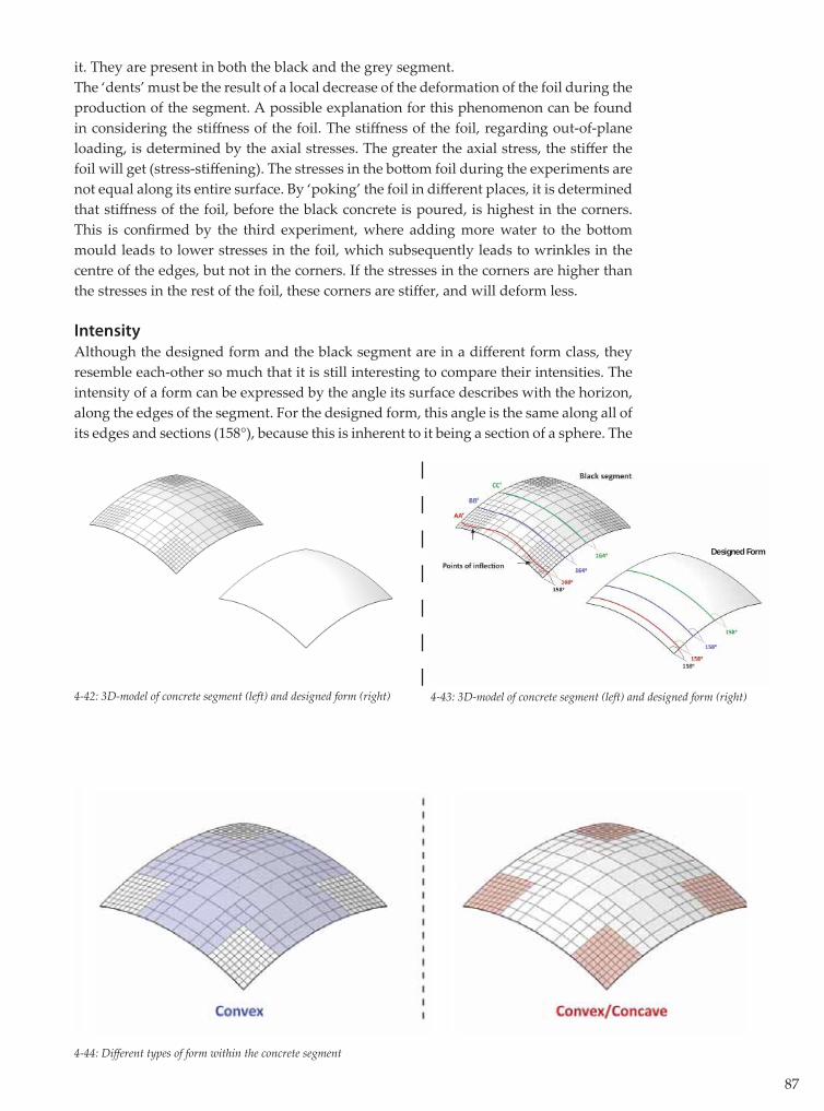
87
it. They are present in both the black and the grey segment.The ‘dents’ must be the result of a local decrease of the deformation of the foil during the production of the segment. A possible explanation for this phenomenon can be found in considering the stiff ness of the foil. The stiff ness of the foil, regarding out-of-plane loading, is determined by the axial stresses. The greater the axial stress, the stiff er the foil will get (stress-stiff ening). The stresses in the bott om foil during the experiments are not equal along its entire surface. By ‘poking’ the foil in diff erent places, it is determined that stiff ness of the foil, before the black concrete is poured, is highest in the corners. This is confi rmed by the third experiment, where adding more water to the bott om mould leads to lower stresses in the foil, which subsequently leads to wrinkles in the centre of the edges, but not in the corners. If the stresses in the corners are higher than the stresses in the rest of the foil, these corners are stiff er, and will deform less. Intensity
Although the designed form and the black segment are in a diff erent form class, they resemble each-other so much that it is still interesting to compare their intensities. The intensity of a form can be expressed by the angle its surface describes with the horizon, along the edges of the segment. For the designed form, this angle is the same along all of its edges and sections (158°), because this is inherent to it being a section of a sphere. The
4-42: 3D-model of concrete segment (left) and designed form (right)
4-44: Diff erent types of form within the concrete segment
4-43: 3D-model of concrete segment (left) and designed form (right)
Designed Form
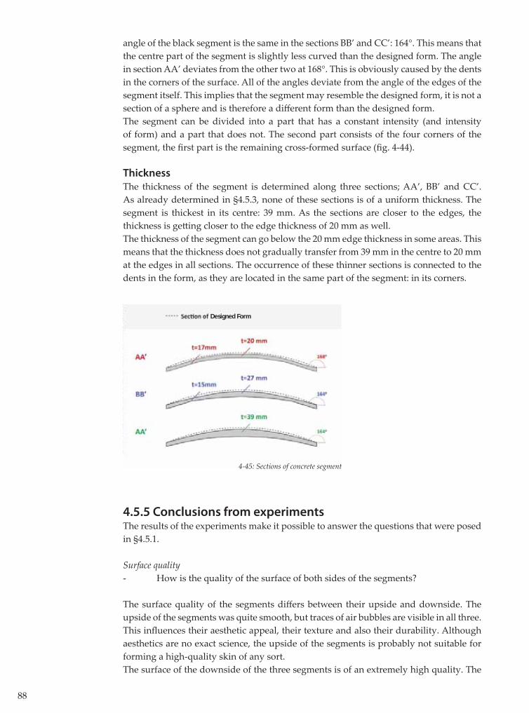
88
angle of the black segment is the same in the sections BB’ and CC’: 164°. This means that the centre part of the segment is slightly less curved than the designed form. The angle in section AA’ deviates from the other two at 168°. This is obviously caused by the dents in the corners of the surface. All of the angles deviate from the angle of the edges of the segment itself. This implies that the segment may resemble the designed form, it is not a section of a sphere and is therefore a diff erent form than the designed form.The segment can be divided into a part that has a constant intensity (and intensity of form) and a part that does not. The second part consists of the four corners of the segment, the fi rst part is the remaining cross-formed surface (fi g. 4-44).
Thickness
The thickness of the segment is determined along three sections; AA’, BB’ and CC’. As already determined in §4.5.3, none of these sections is of a uniform thickness. The segment is thickest in its centre: 39 mm. As the sections are closer to the edges, the thickness is gett ing closer to the edge thickness of 20 mm as well.The thickness of the segment can go below the 20 mm edge thickness in some areas. This means that the thickness does not gradually transfer from 39 mm in the centre to 20 mm at the edges in all sections. The occurrence of these thinner sections is connected to the dents in the form, as they are located in the same part of the segment: in its corners.
4.5.5 Conclusions from experimentsThe results of the experiments make it possible to answer the questions that were posed in §4.5.1.
Surface quality- How is the quality of the surface of both sides of the segments?
The surface quality of the segments diff ers between their upside and downside. The upside of the segments was quite smooth, but traces of air bubbles are visible in all three. This infl uences their aesthetic appeal, their texture and also their durability. Although aesthetics are no exact science, the upside of the segments is probably not suitable for forming a high-quality skin of any sort.The surface of the downside of the three segments is of an extremely high quality. The
4-45: Sections of concrete segment
Designed Form

89
surface is very smooth and mirrors the texture of the foil to the slightest detail. The color is uniform, except for the edges which are slightly lighter.
Form- Can the form class and intensity of the designed form be realized in the form of an actual concrete segment?
The designed form has not been realized. The main diff erence between the black segment and the designed form is their form class. The black segment is convex in its centre, but has four concave ‘dents’ in its corners. The designed segment is completely convex. The intensity of both forms diff ers slightly in the centre. The diff erence is bigger in the dented corners.
Although the segments resemble each other, their diff erences are of signifi cance. If for instance the angle of the tangents along its edges cannot be predicted, it is impossible to produce a segment that connects smoothly to this segment.
- Is it possible to manipulate the intensity of the form of the segment by adjusting the amount of water in the mould?
The intensity of the black and grey panel is clearly diff erent, while the only change in the mould was the amount of water in it. This proves that the intensity of form can indeed be manipulated by adjusting the amount of water.
The adjustment are limited by the minimum volume of water in the bott om mould on one side, and the maximum volume of water before any wrinkles appear on the other side. These values could be adjusted by using other types of foil or altering of the pretension.
- Is it possible to create a segment with a uniform thickness?
The thickness of the segments varies along its sections. The maximum thickness of the grey segment is 39 mm, the minimum thickness is 15 mm, which is less than the thickness at the edges. The thickness seems to gradually increase from the edges of the segment to its centre, but that gradual path is disturbed by the dents in the corners of the segment. It is important to keep this in mind while determining the (structural) design of a segment. The thickness could be overestimated this way, which could lead to the segment being unable to resist the loads it was designed for.The goal of using a countermould however, was to save material and weight in doubly curved segments. This goal has certainly been achieved. A segment of 800x800 mm takes 15 liters of concrete to pour, and weighs some 30 kg. It can easily be handled by two persons, without any heavy equipment.
90
4.6 Conclusions
The goal of this chapter is to answer the sub-question:
‘In what way can the design of a free form-segment be realized using a fabric formwork?’
In order to fi nd this answer, a goal is formulated in the form of a free-form segment design. In trying to meet the design requirements of this segment, a number of experiments have been conducted. A number of conclusions can be drawn from the results and experiences these experiments yield.
- It is possible to construct a mould (800x800 mm) that is air- and watertight, while remaining easy to disassemble. - Using this mould, doubly curved segments can be cast. These segments share an extremely high surface quality at their underside. The surface quality of their upside is not as good.- The mould can be used more than once, but plastic deformations of the foil are to be expected after using it once.
- The thickness of a segment can be reduced drastically by using a top mould and a ballast layer. The consistency of the concrete infl uences the weight of the necessary ballast. The segments are not of uniform thickness, they are thicker in the centre and thinner towards the edges. - The intensity of the form can be controlled by adjusting the amount of water.- The form class of the segment cannot be fully controlled.
Because the aspects of form are intertwined, it is not easy to determine the exact eff ect of each tool of control. The functioning of the mould can be compared to that of a complex machine in which a number of factors are the gears: shape of the edges, volume of water in the bott om mould, amount and division of ballast, applied pre-stress and material properties of the foil, volume and consistency of the concrete. Each factor infl uences each other, and together they determine the fi nal outcome. Only by conducting a large number of experiments, the machine can be calibrated, making it possible to predict its results. The empirical research with the mould shows that the design of a segment can be approximated closely with this type of mould. Also, the results show that the same mould can create multiple forms by adjusting the above factors. These conclusions are based on only three experiments though. Additional research would be necessary to determine the range of forms that can be built with this type of mould, and how these forms can be predicted and controlled.

91


5. Application of Segments in the Building Process

94
5.1 Introduction
The focus of this thesis has been on researching fabform properties and ways of manipulating these properties. This has generated fundamental knowledge on the subject. However, if this knowledge is ever to be implanted in the actual building process, many challenges have to be faced. It is not within the scope of this thesis to resolve these challenges; however it is very useful to list these challenges and any possible solutions. .The purpose of this chapter is to explore these factors and the implications they might have on the design, production and application of the segments. To structurize this process, the challenges are listed by means of a thought-experiment, based on the prefab building process described in §2.5.3. If all of the segments for SDB were already produced, how would the building process elapse?
5.2 Design Challenges
5.2.1 Transport to the siteThe fi rst step in the building process would be to transport the segments to the building site.
SizeThere are three feasible ways of transport; by truck, train or boat. The last two are obviously only possible if both the prefab-factory and building site are in the immediate proximity of water or railroad. Case study SDB is obviously near water, but the location of the prefab factory is unknown. Therefore, the transport is limited to road-transport only. Transport by road can be divided into normal and special transport. Special transport requires additional licenses and therefore takes extra time and money. This could be acceptable in some projects, regarding the particular aesthetic qualities of the segments. For now, the possibility of normal transport is explored. Maximum sizes for the trailer of a standard vehicle-combinations are determined by law, and are circa 12,0 m depth x 2,55 m width x 4,0 m height (in the Netherlands). This maximum size for one segment based on transport can therefore be 12,0 m x 2,9 m (regarding the wheels of the trailer), providing the segment can be transported in an upright position. If the segment can only be transported in a lying down position, the maximum size is 12,0 m x 2,55 m. [6]The given sizes could proof to be quite unrealistic; the maximum size is not always the most effi cient size. In general, one should pursue an effi cient manner of transport and that is achieved by fi lling the loadable volume of a truck to the highest degree possible.
WeightThe maximum weight of a truck and trailer combined, is 60.000 kg by Dutch law. Estimating the weight of the empty truck on 5.000 kg, 55.000 kg is left to fi ll with panels. This means a standard trailer can only be fi lled with concrete for some 20%.
Handling The fi nal segments are thin, but should be designed to be able to resist at least the pouring load of the structural concrete of SDB (or any other structure). This means that

95
the segments are sure to have a certain tensile (and bending) strength and will not break very easily. However, the edges of the segments are vulnerable to chipping off litt le fractions.
On-site prefabricationWhen the transport of the segments proves to be a problem, the option of on-site prefabrication could be considered. The process of casting the segments using fabform is relatively low-tech. No mechanical equipment is required and the only resources that are used in the process are concrete, water and sand. Therefore, the prefabrication of the segments does not necessarily have to take place in an off -site factory. There are two problems with this approach however. First of all, there is the concrete: the preparation of UHPC is a very exact process which would be diffi cult to execute in a temporary production facility. Second, and most important, the conditions in a temporary facility could never be controlled as well as in a permanent factory. These conditions (temperature, humidity etc.) are directly related to the curing of the concrete and its surface quality. In order to achieve a maximum concrete quality, the segments should be cast in a (permanent) factory and the option of on-site prefabrication should be rejected.
5.2.2 Assembly of segmentsOnce the segments have arrived on the site, they will have to be assembled to form the underside of SDB.
Support of segmentsThe segments need to be supported for two reasons. First of all, they need to be able to transfer the pouring loads of the structural concrete to the ground. Secondly, the segments need to be fi xated in the correct place some way. The proposed way of supporting the segments, is by using a steel falsework system. This system will have to consist of a stable framework that can be placed on the ground under the bridge. This framework can either support the segments in a linear way, by using timber beams for example, or it can support the segment in fi xed points only. If the segments are to be supported linearly, it would require producing timber beams that have been curved in exactly the right way beforehand. This is possible but can be quite expensive (fi g. 5-1). The advantage of this approach is that the segments are supported continuously (along certain lines). This will reduce the stresses, and therefore the thickness and possible reinforcement, of the segments. If the segments are supported on a number of points, no expensive beams are necessary. However, the segments will be supported in a less effi cient way. This will have to be compensated by the strength and stiff ness of the segments.
5-1: Linear support in a free form formwork [b]
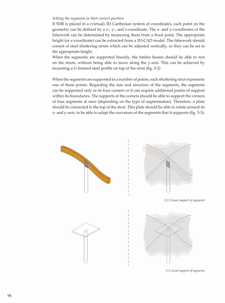
96
Sett ing the segments in their correct positionIf SDB is placed in a (virtual) 3D Carthesian system of coordinates, each point on the geometry can be defi ned by a x-, y-, and z-coordinate. The x- and y-coordinates of the falsework can be determined by measuring them from a fi xed point. The appropriate height (or z-coordinate) can be extracted from a 3D-CAD model. The falsework should consist of steel shutt ering struts which can be adjusted vertically, so they can be set to the appropriate height. When the segments are supported linearly, the timber beams should be able to rest on the struts, without being able to move along the y-axis. This can be achieved by mounting a U-formed steel profi le on top of the strut (fi g. 5-2)
When the segments are supported in a number of points, each shutt ering strut represents one of these points. Regarding the size and structure of the segments, the segments can be supported only in its four corners or it can require additional points of support within its boundaries. The supports at the corners should be able to support the corners of four segments at once (depending on the type of segmentation). Therefore, a plate should be connected to the top of the strut. This plate should be able to rotate around its x- and y-axis, to be able to adapt the curvature of the segments that it supports (fi g. 5-3).
5-2: Linear support of segments
5-3: Local support of segments
97
5.2.3 Structural concrete
Pouring the structural concreteWhen the structural concrete is poured, it is obviously still in a fl uid state. Therefore, it will ooze through the seams between the segments. This will have a devastating eff ect on the aesthetics of the surface, and should therefore be prevented. This can be done quite easily by covering the seams with a watertight fl exible strip of some kind. Because of the high density of the upside of the segments, even a broad type of tape would possibly suffi ce. It would be a good idea to test this kind of practicalities by producing and casting a mock-up of a part of SDB before the actual building process.
Connection between the segments and structural concreteDeformations should be regarded in the prefab fabform system especially, because this system results in a section that consists out of two diff erent types of concrete. The deformations of both types of concrete depend on the following material properties:
- Modulus of elasticity The modulus of elasticity represents the relation between stress and strains within a material. The E-modulus of concrete largely depends on the type of aggregates in the concrete mixture. The type of aggregates is very diff erent for UHPC and regular concrete. Therefore, the deformation of the segment and structural concrete will be diff erent under equal stresses.
- Creep If the load on a concrete structure is increased, its deformations will increase as well. After the load has reached a constant value, the deformations will continue to increase for some time though. This phenomenon is known as creep, and is represented by a creep-coeffi cient. This coeffi cient depends on a number of aspects, such as the strength class of the concrete and the geometry of the section. Both aspects are diff erent in the segment and the structural concrete. Therefore, the creep of both parts of the section of SDB will diff er as well.
- Relaxation When a material is maintained under a certain deformation for a period of time, the stresses in this material will decrease to some extent. This is called relaxation. The magnitude of this relaxation depends on the creep-coeffi cient, and is therefore diff erent for the segment and structural concrete. Diff erent stresses lead to a diff erent deformation between both parts.
- Shrinkage due to drying of concrete After pouring, concrete will shrink due to dehydration. Regarding the section of SDB, the prefabricated segments have already undergone any eff ect of dehydration once they arrive on the site.
The structural concrete is cast in place, and will adhere to the segment. The structural concrete will shrink due to its drying, while the segment will not.

98
It is clear that if the segment and the structural concrete would not be connected to each other, their deformations would diff er. During construction, the segments are supported by a falsework, but after this falsework is removed the segments need to be supported by the structural concrete. Therefore, the segments have to be connected to the structural concrete. There are at least three ways of making this connection (fi g. 5-4):
- Adherence to the structural concrete After pouring the structural concrete onto the segment, the concrete will adhere to the segment. It is questionable though whether this adherence is strong enough to support the entire weight of the segment. The strength of the adherence is directly-proportional to the surface over which the adherence takes place. This surface increases when the upper surface of the segment is rougher. By using an upper mould with a rough textured foil to cast the segments, the strength of the connection will increase.
- Glue It is possible to glue two cured concrete parts together to form a structural connection (fi g. 5-5). If the segment is used as a sacrifi cial formwork, the already cured segment has to be glued to the wet structural concrete.
- Mechanical connection The segment can be mechanically connected to the structural concrete. The most elegant way of doing this would be to cast reinforcement into the segment. This poses some signifi cant challenges for the moulding process of the segment though: a steel cable or rod would have to penetrate the mould while casting the segment. An easier way would be to place a chemical anchor, but this would require drilling a hole thorugh the segments. This would have a devastating eff ect on the asthetics of the surface.
If the 'natural' adherence between the segment and structural concrete would prove to be insuffi cient, the best option would be to glue the two together. A mechanical connection introduces either an increased complexity of the mould (reinforcement), or damages the aesthetics of the concrete surface (chemical anchors). Therefore, this type of connection can be rejected alltogether.
The connection between the segment and structural concrete is one of the most important design challenges that has to be resolved in order to build a free form with fabform segments. The connection should be able to support the segments in the z-direction, but at the same time, diff erences in deformations in the x- and y-direction introduce additional tensions between the two parts of the section.
If the connection is not capable of transferring the occurring stresses, this can cause substantial damage to the bridge. The damage can vary from the occurrence of cracks in the concrete surface to the detachment of entire segments.
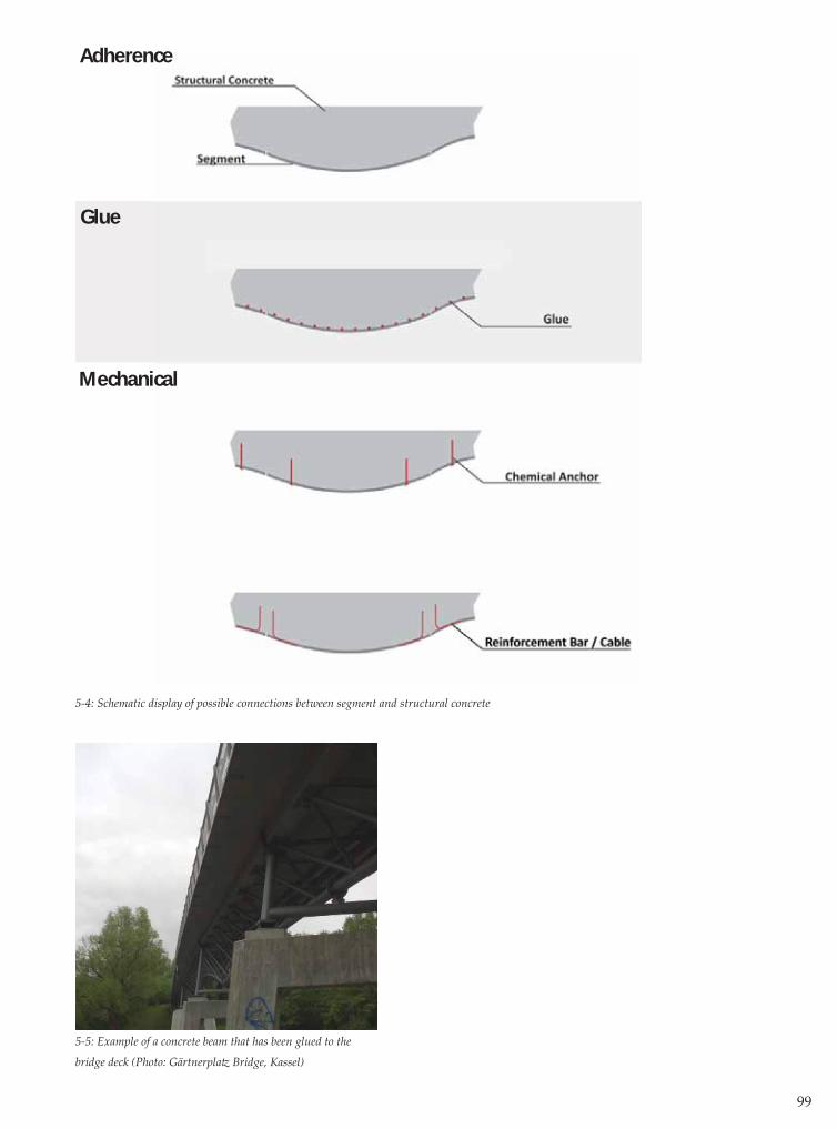
99
5-4: Schematic display of possible connections between segment and structural concrete
Adherence
Glue
Mechanical
5-5: Example of a concrete beam that has been glued to the
bridge deck (Photo: Gärtnerplatz Bridge, Kassel)

100
5.2.4 Utilizing the structure
Once the bridge has been constructed, it will go into use. This means that it will be exposed to traffi c loads, the outside climate, pollution, vandalism etc. These factors infl uence the bridge and its segments as well.
External loadsAfter the pouring stage of the concrete, external eff ects can cause deformations as well:
- Thermal loads Like any other material, concrete will expand or contract depending on its temperature. The magnitude of this thermal deformation is determined by the coeffi cient of thermal expansion and the temperature of the concrete. The coeffi cient depends on the properties of the aggregates and will therefore be diff erent for the segment and structural concrete. The temperature can diff er as well; the underside of the bridge will often be colder than the upside that is exposed to the sun.- Permanent and live loads The main source of deformations in the concrete is obviously the permanent loads resulting from its own weight and the live loads resulting from the usage of the bridge. These loads are transferred to the ground by the structural concrete. The segments are not connected to each other, and therefore are not a part of the structure of the bridge. This would mean that if the structural concrete deforms, the seams between the segments could open up.
DurabilityBecause UHPC is a very dense material, the pores at its surface are very small or absent. This means that aggressive substances can hardly penetrate the surface. If the segments were to be reinforced with steel, this could theoretically justify a thin concrete cover. Another advantage of the high density is that the surface is less sensitive to pollution, as the polluting substances cannot creep into the pores of the concrete.Although the density of the fabform UHPC segments is beyond doubt, the experiment with the regular concrete mixture resulted in a surface that was extremely dense as well. It might be possible that this density is the result of the fabform. This could be explored by conducting additional research.
Aesthetics The surface of the segments is very smooth and even refl ective. It is therefore not necessary to apply any kind of treatment to enhance the appearance of the concrete surace after the bridge has been built. The refl ectivity of the concrete is expected to deteriorate with time, due to the climate-infl uences. The seams between the segments will remain visible. The infl uence of the seams on the aesthetics of the entire surface depends on their width and patt ern. The width of the seams depends on the tolerances of the edges of the prefab segments. The experiments have already shown that the edges can be cast quite precisely because their form depends on the solid edges of the mould. Therefore, it should be possible to make the eff ect of the seams relatively small. If the seams turn out to be clearly visible, the patt ern of the seams can be embraced as an aesthetic tool as well. In that case, aesthetics play an important role in the segmentation of a free form.

101
5.3 Conclusions
The fi nancial and technical feasibility of the prefab fabform system depend on the actual production of the segments, but probably even more on the manner in which these segments can be turned into an actual building.If the system is to be successfully used in the building industry, a number of challenges in the area of transport and assembly have to be overcome. The connection between the structural concrete and the segments form a point of att ention as well. Before the described formwork-system could be succcesfully used in the building industry, the feasibility of the possible solutions for these challenges should be proven in further research.


6. Conclusions and Recommendations
104
6.1 Conclusions6.1.1 Introduction The goal of conducting this research is to answer the research-question that was posed in §2.6.1 that is repeated here:
‘Can a formwork out of prefabricated segments, produced with fabric formwork, perform bett er than existing formwork systems in building free forms in concrete?’
Experiments have shown that fabric formwork (fabform) results in concrete segments with an extremely high surface quality. The technical and fi nancial feasibility has yet to be proven though.The research has resulted in new knowledge on the subject of fabric formwork. This new knowledge is used to assess the feasibility and properties of the proposed formwork technique. Finally, the formwork system is compared to existing formwork techniques.
6.1.2 Technical feasibilityThe technical feasibility of the proposed formwork system depends on the ability to translate a free form design into an actual concrete surface, while achieving a high surface quality and maintaining the continuity of the free form. To achieve continuity of form, it should be possible to predict and control ‘intensity of form’ (as defi ned in §4.5.4).The following conclusions can be drawn from the research:
- It is possible to cast doubly curved segments (800x800 mm) using a fabric formwork mould, as described in chapter 4. The surface quality of the segments that are cast with this mould is very high on one side.
- With this mould, the intensity of the segment can be infl uenced, but the experiments have not resulted in complete control over the intensity nor form class of the segments.
6.1.3 Financial feasibilityAlthough the design and construction of a mould is relatively low-tech, it is not feasible to build a new mould for every single segment in a free form. Therefore, the fi nancial feasibility of the proposed formwork system partly depends on the possibility of re-using a mould for casting diff erent segments. The other requirement for fi nancial feasibility is to be able to limit the amount of UHPC per segment by casting segments of uniform thickness. The following conclusions can be drawn from the research:
- It is possible to cast two concrete segments with a diff erent intensity of form using the same mould, by adjusting the volume of water in the bott om mould.
- It is possible to limit the thickness of a concrete segment by applying a ballast and countermould.

105
6.1.4 Comparison between existing formwork systems and fabric formwork system
If the technical and fi nancial feasibility was to be proven, how would the prefab fabform system relate to the existing formwork systems for casting free forms in concrete?To answer this question, the seven criteria from §2.4 are regarded once again, in comparison to the exisiting formwork systems.
1. Freedom of Form The freedom of form within a single segment of the fabform system is limited compared to that of other systems, but can be increased signifi cantly by combining segments to a free form.
2. Accuracy of cast concrete form The accuracy of the free forms depends on the ability to control the form and intensity of the segments. The extent to which these factors can be controlled is yet to be determined.
3. Concrete surface quality (without fi nishing) All experiments have shown that the surface quality of fabform segments is extraordinary compared to the quality that can be achieved using other formwork systems. 4. Reusability formwork The experiments with the large mould show that, when using ETFE-foil, the foil deforms plastically from producing a segment. To reproduce the same segment, the foil has to be replaced.
Several diff erent forms of segments can be made using the same mould, by adjusting the volume of water in it. However, these forms diff er only in intensity, not in form class. The reusability of the formwork for producing a diff erent segment depends on the (possible) development of a mould that can adjust the factor that determines the form class, the shape of the edges.
5. Labour intensity (formwork) The labour intensity depends largely on the labour in making the prefab segments, which in turn depends on the number of moulds that has to be built. Additional research on the possibilities of an adaptable mould is necessary to be able to assess the labour intensity of the system.
6. Labour skill In constructing the large mould, a CNC-milling device was used. Aside from using this high-tech equipment, the construction of the moulds is a low skilled job. If the moulds were to be produced in larger numbers, additional research into the optimization and simplifi cation of the construction of the mould is required.
106
7. Cost The material costs rely on the type of concrete that is used as well as the number of moulds that need to be constructed to produce a specifi c free form. The cost of the formwork system is therefore closely connected to the reusability of the formwork.
6.1.5 General conclusionThe proposed fabric formwork system is superior to the existing formwork techniques in the area of surface quality. Besides the aesthetic advantages of a high surface quality, the high density of the surface provides a high durability of the surface. When these aspects are crucial to the design of a free form, fabric formwork should be considered for its realization.If it proves to be possible to construct a mould with adaptable edges, the system could be considered highly competitive in the fi eld of free-form moulds. To be able to build actual free form-structures using fabric formwork, the technical and fi nancial feasibility of the system have to be proven. Research into this specifi c application of fabric formwork is limited to this thesis (to the author’s knowledge). Additional research is necessary in order to prove the potential of prefabricated fabric formwork.
6.2 Recommendations
The research in this thesis can be regarded as a fi rst exploration of the properties and possibilities of the fabric formwork system. Therefore, there are a large number of aspects yet to be researched. The most important aspects are listed below.
Recommendations regarding technical feasibility- The experiments with the large mould have resulted in three variations of a single form of concrete segment. In order to build free forms with fabform segments, other forms have to be available as well. To be able to produce other forms, new moulds have to be designed, built and experimented with. An important challenge can be found in the production of a segment of which the underside is concave instead of the convex segments that have been produced so far. This could possibly be achieved by ‘infl ating’ the bott om mould with water.
- In order to use the segments in a building process, the form of the segments has to be predicted and controlled. The eff ect of each tool of control on the form of the segment has been explored qualitatively. If the form of the segment is to be controlled in detail, the eff ect of these tools has to be researched in a quantitative way as well. To achieve this, a large number of experiments need to be conducted, next to a numerical research into the structural workings of the mould.
- The challenges regarding the connection between the segments and the structural concrete, as described in §5.2.3 should be researched in greater detail. A possible connection should be designed and analyzed.
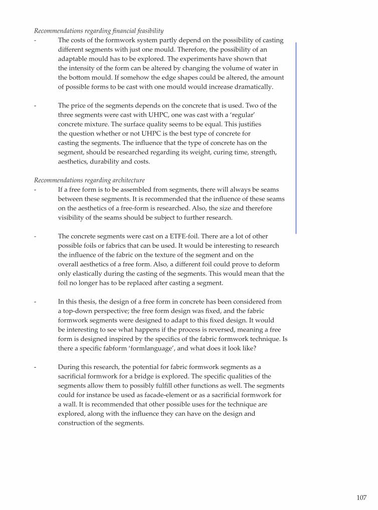
107
Recommendations regarding fi nancial feasibility- The costs of the formwork system partly depend on the possibility of casting diff erent segments with just one mould. Therefore, the possibility of an adaptable mould has to be explored. The experiments have shown that the intensity of the form can be altered by changing the volume of water in the bott om mould. If somehow the edge shapes could be altered, the amount of possible forms to be cast with one mould would increase dramatically.
- The price of the segments depends on the concrete that is used. Two of the three segments were cast with UHPC, one was cast with a ‘regular’ concrete mixture. The surface quality seems to be equal. This justifi es the question whether or not UHPC is the best type of concrete for casting the segments. The infl uence that the type of concrete has on the segment, should be researched regarding its weight, curing time, strength, aesthetics, durability and costs.
Recommendations regarding architecture- If a free form is to be assembled from segments, there will always be seams between these segments. It is recommended that the infl uence of these seams on the aesthetics of a free-form is researched. Also, the size and therefore visibility of the seams should be subject to further research.
- The concrete segments were cast on a ETFE-foil. There are a lot of other possible foils or fabrics that can be used. It would be interesting to research the infl uence of the fabric on the texture of the segment and on the overall aesthetics of a free form. Also, a diff erent foil could prove to deform only elastically during the casting of the segments. This would mean that the foil no longer has to be replaced after casting a segment.
- In this thesis, the design of a free form in concrete has been considered from a top-down perspective; the free form design was fi xed, and the fabric formwork segments were designed to adapt to this fi xed design. It would be interesting to see what happens if the process is reversed, meaning a free form is designed inspired by the specifi cs of the fabric formwork technique. Is there a specifi c fabform ‘formlanguage’, and what does it look like?
- During this research, the potential for fabric formwork segments as a sacrifi cial formwork for a bridge is explored. The specifi c qualities of the segments allow them to possibly fulfi ll other functions as well. The segments could for instance be used as facade-element or as a sacrifi cial formwork for a wall. It is recommended that other possible uses for the technique are explored, along with the infl uence they can have on the design and construction of the segments.


Acknowledgements

110

111
Writing a thesis is rarely a one-man eff ort. I would like to express my sincere gratitude to the following persons who have all helped me a great deal in conducting my research: - my graduating committ ee, consisting of prof. dr. ir. Dick Hordijk, ir. Gerald Lindner, prof. ir. Frans van Herwijnen and Dipl-Ing. Gregor Zimmermann.
- Steff en Grunewald and Ton Franzen of Hurks Beton (Veldhoven), for providing the concrete and helping me to cast the concrete segments;
- the employees of the student workshop at the faculty of Architecture, Building and Planning (TU/e), and especially Toon van Alen, for helping me design and construct the large mould;
- Frank Huijben, for sharing his knowledge (and contacts) regarding foils;
- Kees van der Donk of Vreeberg bv, for providing the foil for the small-scale experiments;
- Erwin van Maaren and René Homan of Nedcam, for sharing their knowledge on the construction of Spencer Dock Bridge;
- Gertjan Rohaan and Jikke Reinten, for reading and correcting the chapters of this report.


References

114

115
Literature
[1] Literatuurstudie: Vrije vormen in beton Rob Verhaegh, 2009[2] The Art of Structural Design, a Swiss Legacy David P.l Billington, Princeton University Art Museum, 2003[3] Website Nedcam BV htt p://www.nedcam.nl[4] Size Matt ers: Digital Manufactering in Architecture Fabian Scheurer From: Dimension, Emily Abruzzo and Jonathan D. Salomon (editors), Princeton Architectural Press, 2009[5] Zeerhogesterktebeton Toepassingen N. Kaptijn, Adviesbureau ir. J.G. Hageman BV, 2007[6] website ‘Rijksdienst voor het Wegverkeer’ (ministerie van VROM); exceptioneel transport htt p://tet.rdw.nl[7] Website cement en betoncentrum, article ‘Vervormingseigenschappen’ htt p://www.cementenbeton.nl
Figures[a] Thin Shell Concrete Structures David P. Billington, McGraw-Hill, 1982[b] Heinz Isler: Schalen Ekkehard Ramm and Eberhard Schunck, vdf Hochschulverlag an der ETH Zürich, 2002[c] Robert Maillart and the art of reinforced concrete David P. Billington, The MIT Press, 1990[d] Steven Gelderman en ir. René Houtman - Dubbelgekromde betonmallen From: Cement 5, 2009. [e] Gidon Fuehrer [ AL_A Team], from htt p://www.yatz er.com[f] C.A.S.T. booklet From htt p://www.umanitoba.ca/cast_building/[g] Picture was provided by Nedcam BV[h] Felix Candela, 1958 From htt p://www.greatbuildings.com/ [i] Wikipedia From: www.wikipedia.org; article on Toyo Ito

116

Appendices
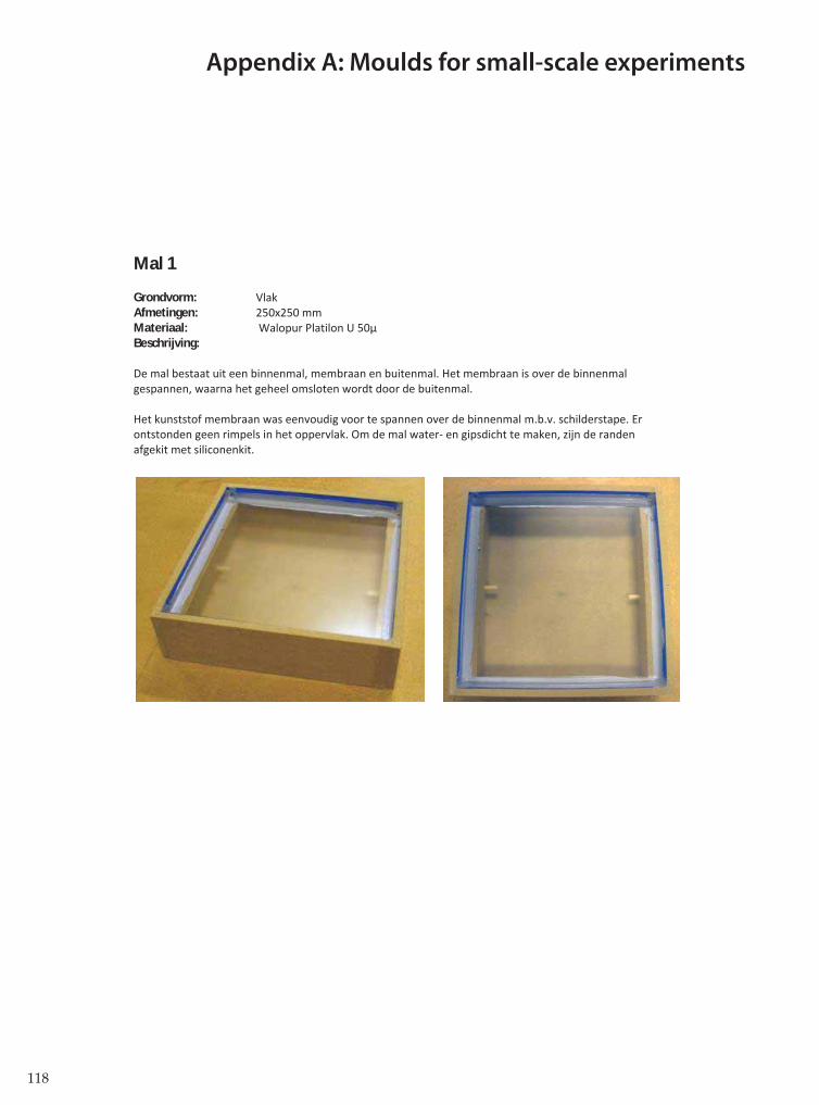
118
Mal 1
Grondvorm: VlakAfmetingen: 250x250 mmMateriaal: Walopur Platilon U 50μBeschrijving:
De mal bestaat uit een binnenmal, membraan en buitenmal. Het membraan is over de binnenmalgespannen, waarna het geheel omsloten wordt door de buitenmal.
Het kunststof membraan was eenvoudig voor te spannen over de binnenmal m.b.v. schilderstape. Erontstonden geen rimpels in het oppervlak. Om de mal water en gipsdicht te maken, zijn de randenafgekit met siliconenkit.
Appendix A: Moulds for small-scale experiments

119
Mal 2
Grondvorm: Hypparschaal (dubbelgekromd)Afmetingen: 250x250 mmMateriaal: Walopur Platilon U 50μBeschrijving:
De mal bestaat uit een binnenmal, membraan en buitenmal. Het membraan is over de binnenmalgespannen, waarna het geheel omsloten wordt door de buitenmal.
Het kunststof membraan was eenvoudig voor te spannen over de binnenmal m.b.v. schilderstape. Erontstonden geen rimpels in het oppervlak. Om de mal water en gipsdicht te maken, zijn de randenafgekit met siliconenkit.
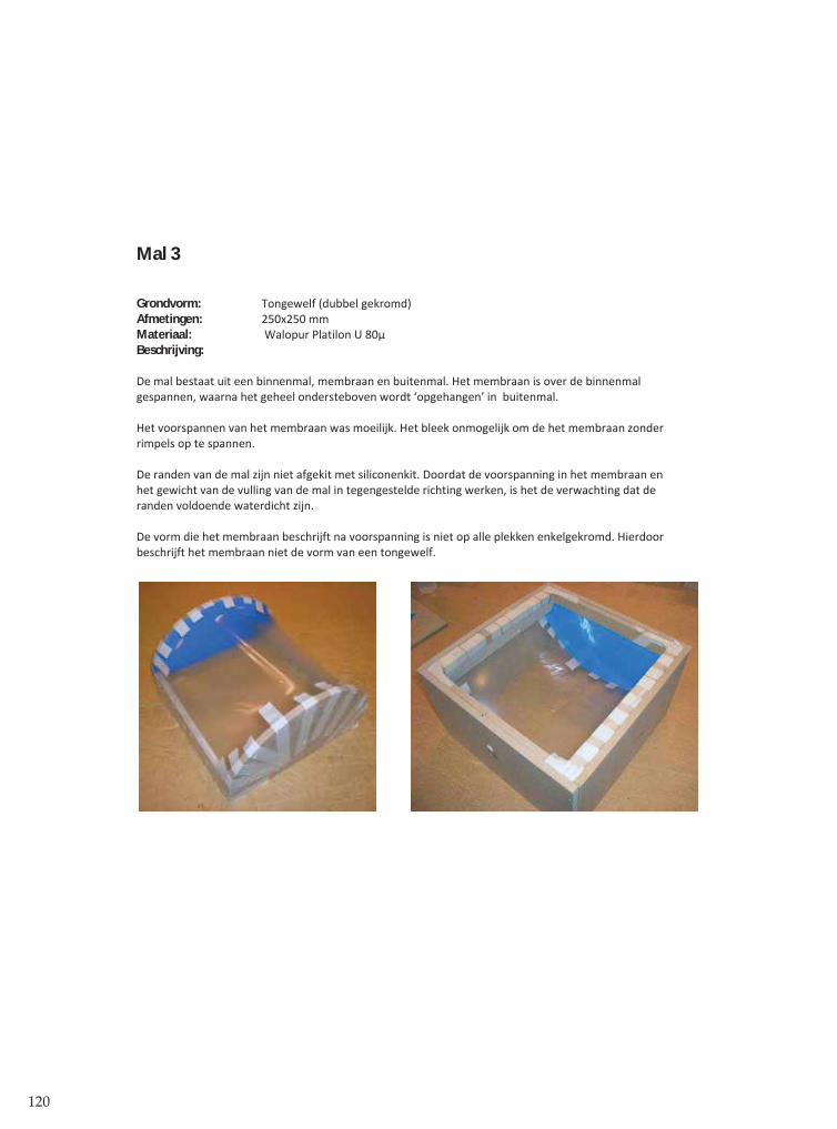
120
Mal 3
Grondvorm: Tongewelf (dubbel gekromd)Afmetingen: 250x250 mmMateriaal: Walopur Platilon U 80μBeschrijving:
De mal bestaat uit een binnenmal, membraan en buitenmal. Het membraan is over de binnenmalgespannen, waarna het geheel ondersteboven wordt ‘opgehangen’ in buitenmal.
Het voorspannen van het membraan was moeilijk. Het bleek onmogelijk om de het membraan zonderrimpels op te spannen.
De randen van de mal zijn niet afgekit met siliconenkit. Doordat de voorspanning in het membraan enhet gewicht van de vulling van de mal in tegengestelde richting werken, is het de verwachting dat deranden voldoende waterdicht zijn.
De vorm die het membraan beschrijft na voorspanning is niet op alle plekken enkelgekromd. Hierdoorbeschrijft het membraan niet de vorm van een tongewelf.
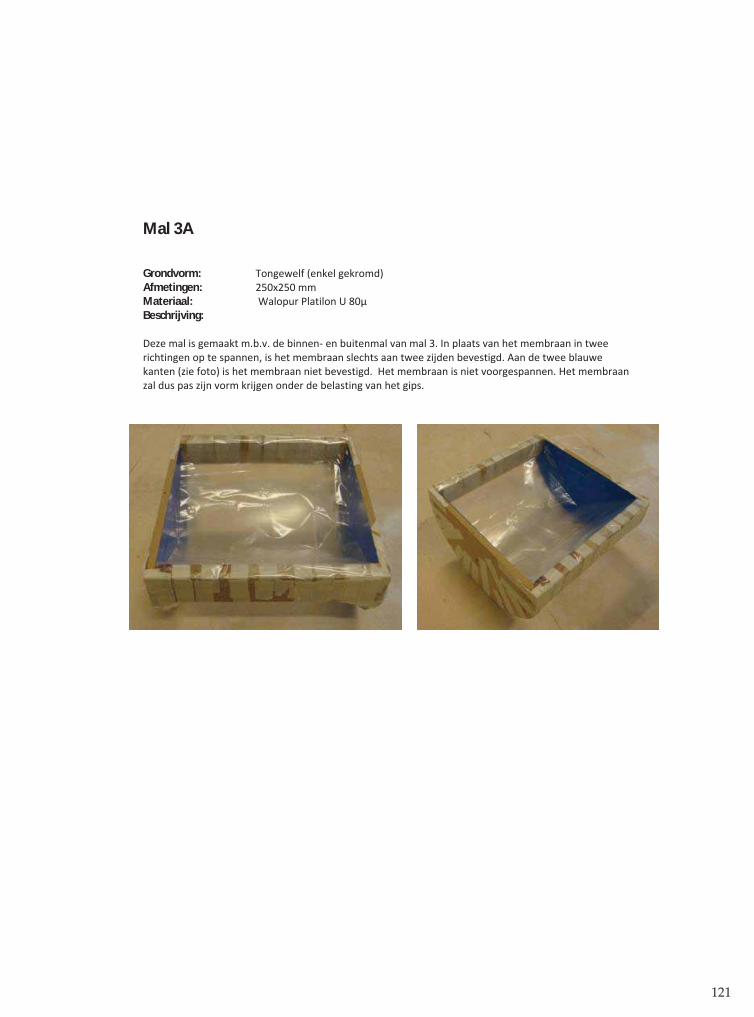
121
Mal 3A
Grondvorm: Tongewelf (enkel gekromd)Afmetingen: 250x250 mmMateriaal: Walopur Platilon U 80μBeschrijving:
Deze mal is gemaakt m.b.v. de binnen en buitenmal van mal 3. In plaats van het membraan in tweerichtingen op te spannen, is het membraan slechts aan twee zijden bevestigd. Aan de twee blauwekanten (zie foto) is het membraan niet bevestigd. Het membraan is niet voorgespannen. Het membraanzal dus pas zijn vorm krijgen onder de belasting van het gips.
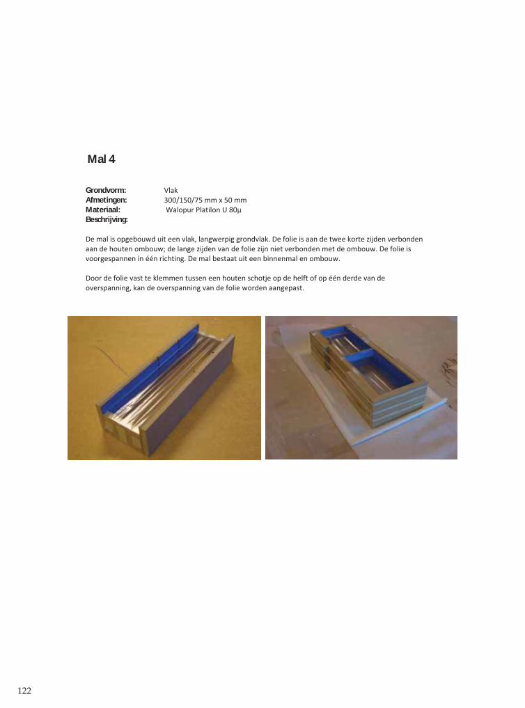
122
Mal 4
Grondvorm: VlakAfmetingen: 300/150/75 mm x 50 mmMateriaal: Walopur Platilon U 80μBeschrijving:
De mal is opgebouwd uit een vlak, langwerpig grondvlak. De folie is aan de twee korte zijden verbondenaan de houten ombouw; de lange zijden van de folie zijn niet verbonden met de ombouw. De folie isvoorgespannen in één richting. De mal bestaat uit een binnenmal en ombouw.
Door de folie vast te klemmen tussen een houten schotje op de helft of op één derde van deoverspanning, kan de overspanning van de folie worden aangepast.
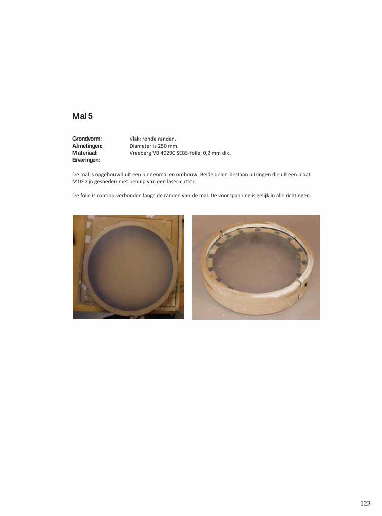
123
Mal 5
Grondvorm: Vlak; ronde randen.Afmetingen: Diameter is 250 mm.Materiaal: Vreeberg VB 4029C SEBS folie; 0,2 mm dik.Ervaringen:
De mal is opgebouwd uit een binnenmal en ombouw. Beide delen bestaan uitringen die uit een plaatMDF zijn gesneden met behulp van een laser cutter.
De folie is continu verbonden langs de randen van de mal. De voorspanning is gelijk in alle richtingen.
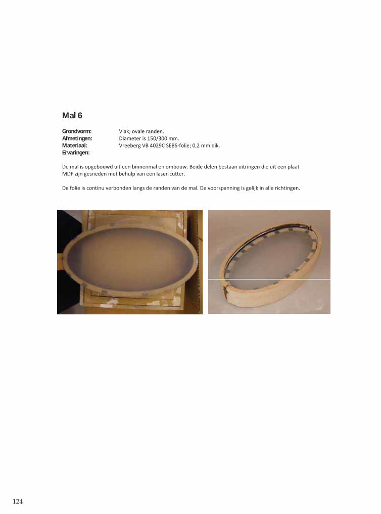
124
Mal 6
Grondvorm: Vlak; ovale randen.Afmetingen: Diameter is 150/300 mm.Materiaal: Vreeberg VB 4029C SEBS folie; 0,2 mm dik.Ervaringen:
De mal is opgebouwd uit een binnenmal en ombouw. Beide delen bestaan uitringen die uit een plaatMDF zijn gesneden met behulp van een laser cutter.
De folie is continu verbonden langs de randen van de mal. De voorspanning is gelijk in alle richtingen.
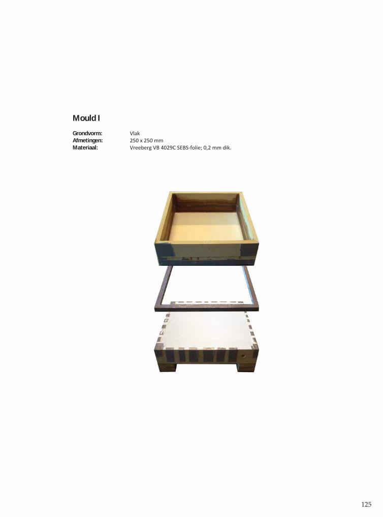
125
Mould I
Grondvorm: VlakAfmetingen: 250 x 250 mmMateriaal: Vreeberg VB 4029C SEBS folie; 0,2 mm dik.
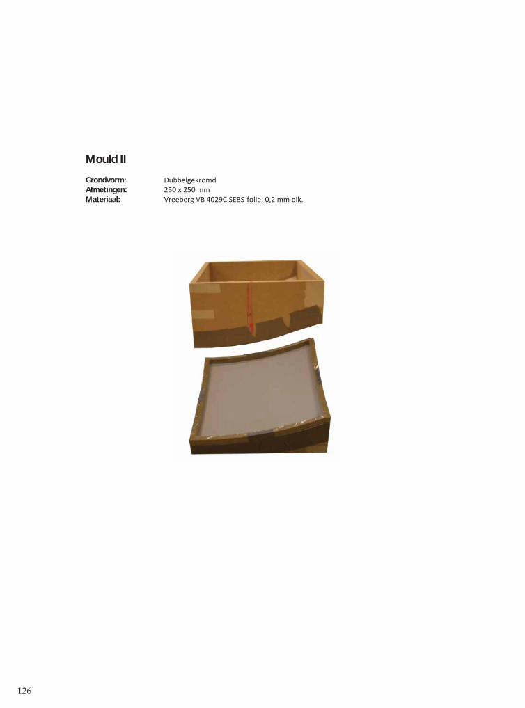
126
Mould II
Grondvorm: DubbelgekromdAfmetingen: 250 x 250 mmMateriaal: Vreeberg VB 4029C SEBS folie; 0,2 mm dik.

127
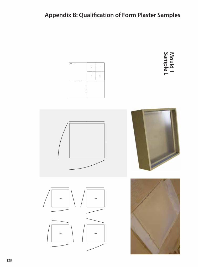
128
12
34
symm
etrie-as
symmetrie-as
1L
13
24
Mo
uld
1S
am
ple
L
Appendix B: Qualifi cation of Form Plaster Samples
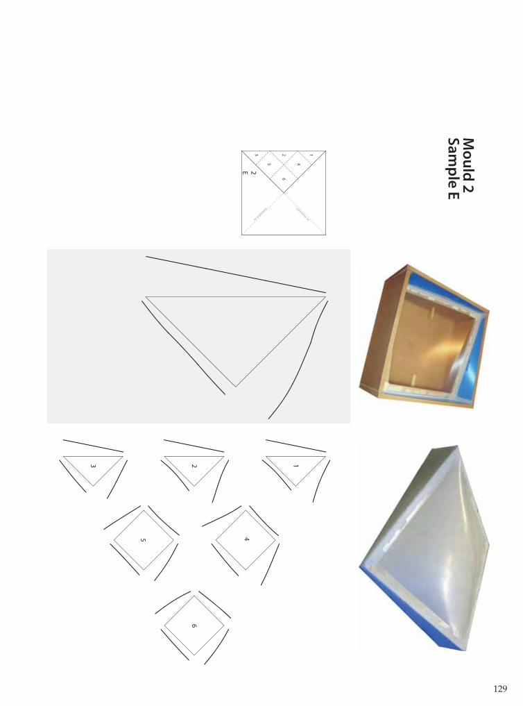
129
symmetrie-as
symmetrie-as
2E
123
45
6
123
45
6
Mo
uld
2S
am
ple
E
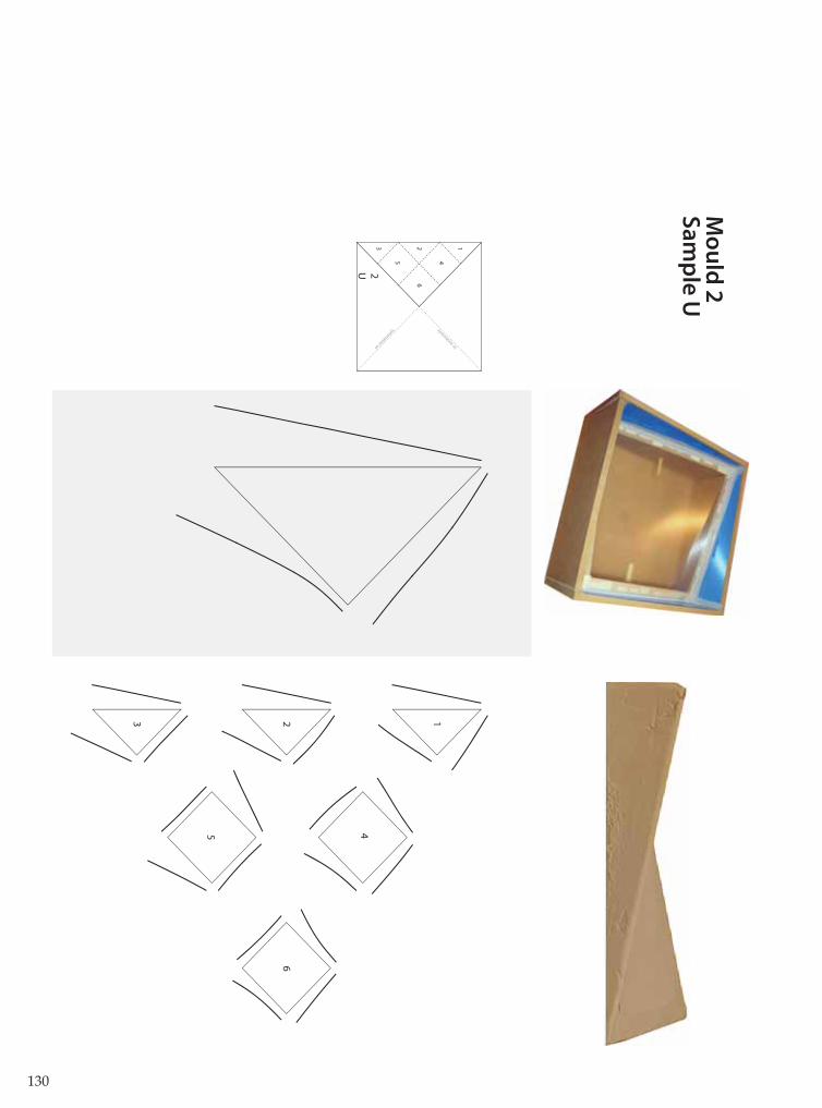
130
123
45
6
symmetrie-as
symmetrie-as
2U
123
45
6
Mo
uld
2S
am
ple
U

131
13
24
12
34
3D
symm
etrie-as
symmetrie-as
Mo
uld
3S
am
ple
D

132
12
3A/4
F
symm
etrie-as
symm
etrie-as
symm
etrie-as
symmetrie-as
12
Mo
uld
3A
Sa
mp
le F
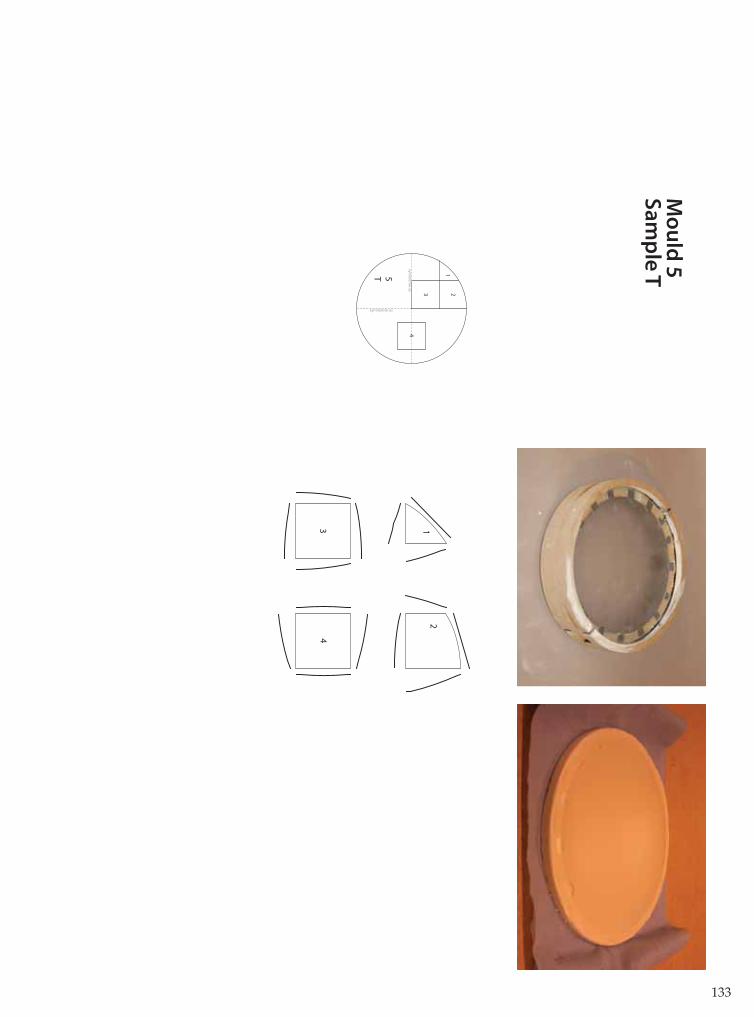
133
123
4sym
metrie-as
symmetrie-as
5T
12
34
Mo
uld
5S
am
ple
T
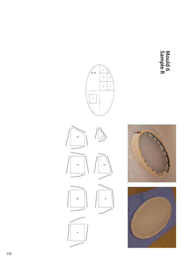
134
symm
etrie-as
symmetrie-as
12
3
54
6
76R
12
3
45
67
Mo
uld
6S
am
ple
R

135
Sa
mp
les h
igh
ligh
ted
in
ran
ge
of p
ossib
le fo
rms

136
Appendix C: Small-scale experiments with fabric formwork, mould I and II
Experiment U
Goal: To produce a segment of uniform thickness and at least one surface of perfect quality.
Gypsum: 750 ml (1,05 kg)
Ballast: 620 ml (1,05 kg); sand 0 3 mm
Results:
Req. 1: surfaceThe surface quality on the underside is perfect.The quality of the upside is mediocre; the gypsum is soft and numerous air bubbles have left their markson the surface
Req 2: continuity of form
Req. 3: Uniform thickness
The segment is not of uniform thickness. The section of the segment is thin at the edges and thick in themiddle. There is a small indentation in the centre of the segment.
Conclusions:
The weight of the ballast should be higher than the weight of the gypsum; the assumption that the sameweight on each foil should result in a uniform thickness is based on a fallacy. If the load and pretension onboth membranes is the same, then both membranes would have the same deflection, providing thebottom membrane does not support the top membrane. In this case, the bottom membrane does supportthe upper membrane, increasing the deflection of the bottom membrane and decreasing the deflection ofthe top membrane.The quality of the top surface is mediocre; this will not suffice for a panel in sight. If it is possible toproduce a segment with two perfect quality surfaces, then both segments of geometry 1 are the same(flipped over). This could be achieved by changing the ballast material.
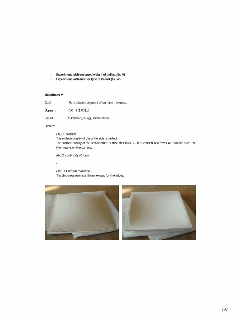
137
Experiment with increased weight of ballast (Ex. V)Experiment with another type of ballast (Ex. W)
Experiment V
Goal: To produce a segment of uniform thickness.
Gypsum: 750 ml (1,05 kg)
Ballast: 2000 ml (3,39 kg), sand 0 3 mm
Results:
Req. 1: surfaceThe surface quality of the underside is perfect.The surface quality of the upside is better than that in ex. U , it is less soft and fewer air bubbles have lefttheir marks on the surface.
Req 2: continuity of form
Req. 3: Uniform thicknessThe thickness seems uniform, except for the edges.
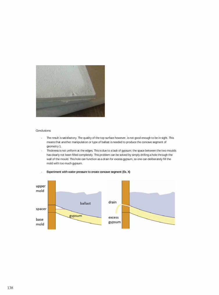
138
Conclusions:
The result is satisfactory. The quality of the top surface however, is not good enough to be in sight. Thismeans that another manipulation or type of ballast is needed to produce the concave segment ofgeometry 1.Thickness is not uniform at the edges. This is due to a lack of gypsum; the space between the two mouldshas clearly not been filled completely. This problem can be solved by simply drilling a hole through thewall of the mould. This hole can function as a drain for excess gypsum, so one can deliberately fill themold with too much gypsum.
Experiment with water pressure to create concave segment (Ex. X)

139
Experiment W
Goal: To produce a segment of uniform thickness with two surfaces of perfect quality.
Gypsum: 750 ml (1,05 kg)
Ballast: 3120 ml (3,12 kg), water
NB. It was initially intended to add 3,4 kg of ballast, the same as in ex. V. Due to the limitedheight of the upper mold, this was not possible.
Results:
Req. 1: surfaceThe surface quality of the underside is perfect.The surface quality of the upside is marginally better than in ex. V (sand).
Req 2: continuity of form
Req. 3: Uniform thickness
The segment is of uniform thickness, except for the edges. The non uniform ‘strip’ around the edges isbroader than in ex. V.
Conclusions:
The edge problem of ex V is even larger in this experiment. A possible cause for this problem is thedecrease of ballast in comparison to ex V (3,12 vs 3,4 kg).The quality of the top surface however, is not good enough to be in sight. The technique, as it is used inthis experiment, is not suitable for creating concave elements.
Experiment with water pressure to create concave segment (Ex. X)

140
Experiment X
Goal: To produce a concave segment of uniform thickness.
Gypsum: 750 ml (1,05 kg)
Ballast (base): 3200 ml (3,20 kg), water
NB. The base mold suffered heavy leakage after filling it with water. The initial bulging of themembrane, needed to create a concave form, quickly disappeared due to this leakage. After 5min the mold was turned upside down, in an attempt to recreate experiment X.
Results:
Req. 1: surfaceThe surface quality of both the upside as the underside is perfect.
Req 2: continuity of formThe form has a light curvature in one direction, but is not uniform.
Req. 3: Uniform thicknessThe segment is hollow. The upside contains a large hole. The inside is shaped like a random ‘moonscape’.
Conclusions:
The experiment did not go as planned, but produced an interesting result. Both surfaces are of perfectquality. This means that the conclusion that it is not possible to create two perfect surfaces with thistechnique is premature.The segment is hollow and random. This is probably the result of the flipping over of the mold, after whicha thin shell of the gypsum has hardened enough to resist the load of the water, after which the gypsumthat was still liquid sank to the bottom membrane.
Experiment with water as a top ballast to create concave segment again (Ex. Y)

141
Experiment Y
Goal: To produce a segment of uniform thickness with two surfaces of perfect quality.
Gypsum: 750 ml (1,05 kg)
Ballast: 5200 ml (5,2 kg), water
NB. Mold 7 has been altered for this experiment. The upper mold has been heightened tocontain more water.
Results:
Req. 1: surfaceThe surface quality of the underside is perfect.The surface quality of the upside is comparable to that of ex W.
Req 2: continuity of form
Req. 3: Uniform thicknessThe segment is not of uniform thickness. The segment is thick in the middle; the edges are very thin.
Conclusions:
The gypsum was not completely ’pushed’ to the edges.Heightening the ballast is no solution for dividing the gypsum more evenly. In fact, it has workedcounterproductive; the problem is larger than in ex W.There is another cause for this problem.
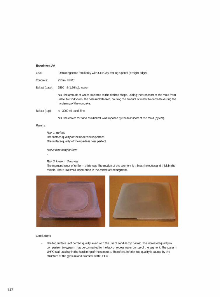
142
Experiment AA
Goal: Obtaining some familiarity with UHPC by casting a panel (straight edge).
Concrete: 750 ml UHPC
Ballast (base): 1560 ml (1,56 kg), water
NB. The amount of water is related to the desired shape. During the transport of the mold fromKassel to Eindhoven, the base mold leaked, causing the amount of water to decrease during thehardening of the concrete.
Ballast (top): +/ 3000 ml sand, fine
NB. The choice for sand as a ballast was imposed by the transport of the mold (by car).
Results:
Req. 1: surfaceThe surface quality of the underside is perfect.The surface quality of the upside is near perfect.
Req 2: continuity of form
Req. 3: Uniform thicknessThe segment is not of uniform thickness. The section of the segment is thin at the edges and thick in themiddle. There is a small indentation in the centre of the segment.
Conclusions:
The top surface is of perfect quality, even with the use of sand as top ballast. The increased quality incomparison to gypsum may be connected to the lack of excess water on top of the segment. The water inUHPC is all used up in the hardening of the concrete. Therefore, inferior top quality is caused by thestructure of the gypsum and is absent with UHPC.

143
The upside of the segment is flat in the middle; the segment has touched the bottom of the mold there.This is probably due to the leaking of the water from the base mold.The UHPC is much heavier then the gypsum, leading to a larger deflection of the membrane and largercurvature of the segment.
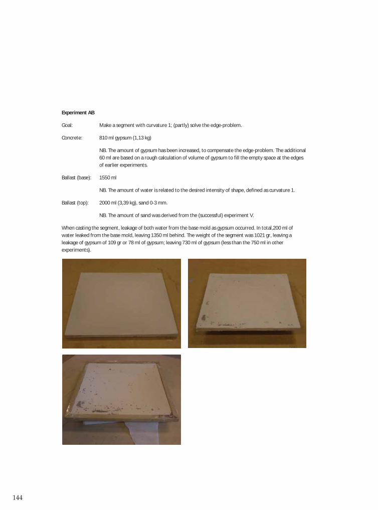
144
Experiment AB
Goal: Make a segment with curvature 1; (partly) solve the edge problem.
Concrete: 810 ml gypsum (1,13 kg)
NB. The amount of gypsum has been increased, to compensate the edge problem. The additional60 ml are based on a rough calculation of volume of gypsum to fill the empty space at the edgesof earlier experiments.
Ballast (base): 1550 ml
NB. The amount of water is related to the desired intensity of shape, defined as curvature 1.
Ballast (top): 2000 ml (3,39 kg), sand 0 3 mm.
NB. The amount of sand was derived from the (successful) experiment V.
When casting the segment, leakage of both water from the base mold as gypsum occurred. In total,200 ml ofwater leaked from the base mold, leaving 1350 ml behind. The weight of the segment was 1021 gr, leaving aleakage of gypsum of 109 gr or 78 ml of gypsum; leaving 730 ml of gypsum (less than the 750 ml in otherexperiments).

145
Results:
Req. 1: surfaceThe surface quality of the underside is perfect.The surface quality of the upside is comparable to ex. V. the surface is polluted with some grey spots, aresult from the previous usage of the mold using concrete.
Req 2: continuity of form
Req. 3: Uniform thicknessThe segment is of uniform thickness. Also, the edge problem seems less significant than in otherexperiments.
Conclusions:
The edge problem can probably be solved by adding extra gypsum. The proposed solution is likely tofunction properly.Due to the leakage of the mold, it will be difficult to reproduce ‘curvature 1’.
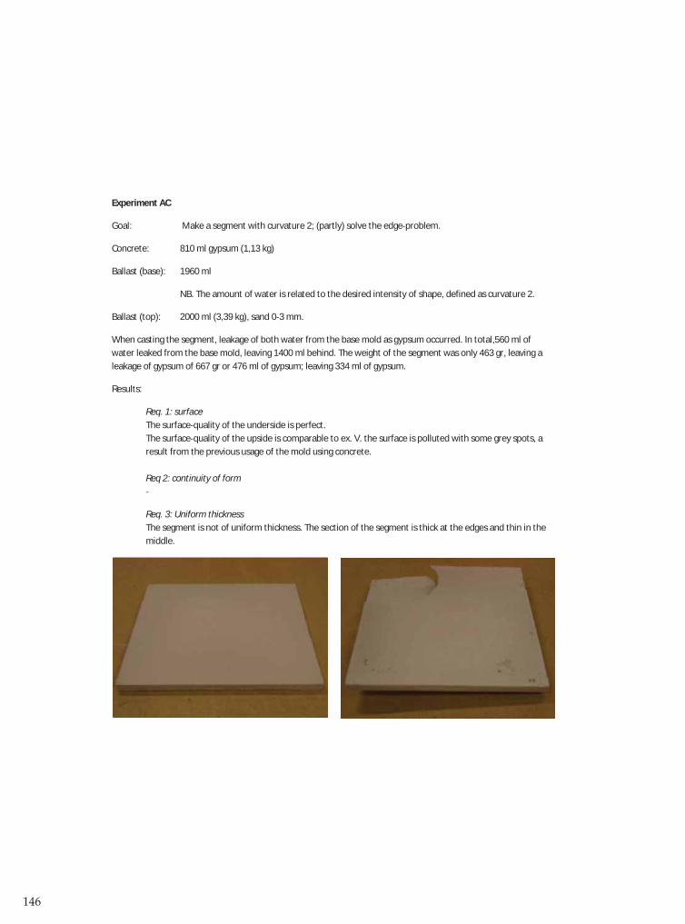
146
Experiment AC
Goal: Make a segment with curvature 2; (partly) solve the edge problem.
Concrete: 810 ml gypsum (1,13 kg)
Ballast (base): 1960 ml
NB. The amount of water is related to the desired intensity of shape, defined as curvature 2.
Ballast (top): 2000 ml (3,39 kg), sand 0 3 mm.
When casting the segment, leakage of both water from the base mold as gypsum occurred. In total,560 ml ofwater leaked from the base mold, leaving 1400 ml behind. The weight of the segment was only 463 gr, leaving aleakage of gypsum of 667 gr or 476 ml of gypsum; leaving 334 ml of gypsum.
Results:
Req. 1: surfaceThe surface quality of the underside is perfect.The surface quality of the upside is comparable to ex. V. the surface is polluted with some grey spots, aresult from the previous usage of the mold using concrete.
Req 2: continuity of form
Req. 3: Uniform thicknessThe segment is not of uniform thickness. The section of the segment is thick at the edges and thin in themiddle.
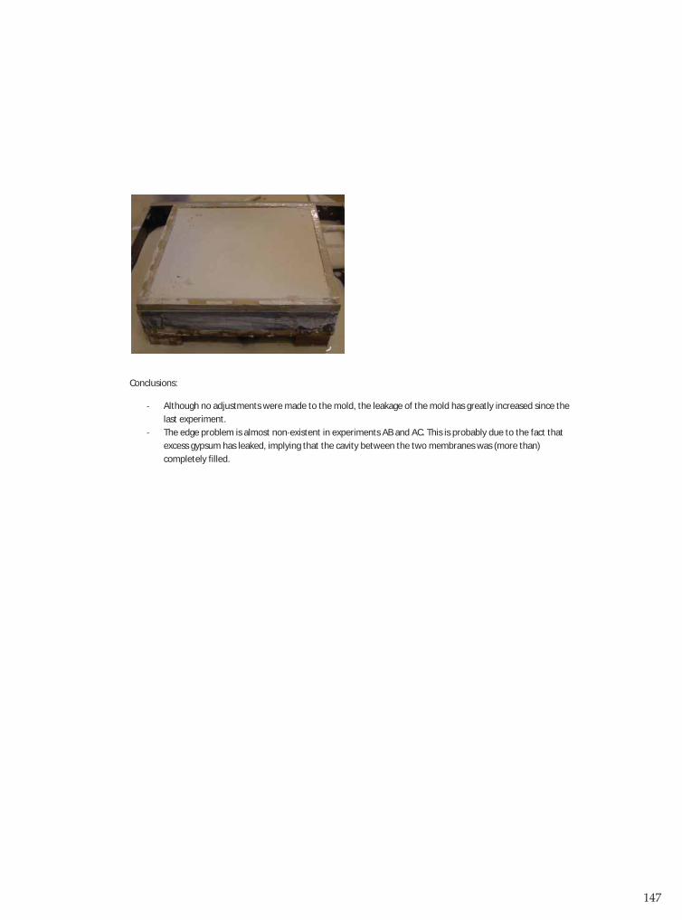
147
Conclusions:
Although no adjustments were made to the mold, the leakage of the mold has greatly increased since thelast experiment.The edge problem is almost non existent in experiments AB and AC. This is probably due to the fact thatexcess gypsum has leaked, implying that the cavity between the two membranes was (more than)completely filled.
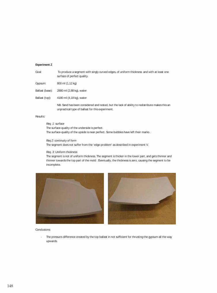
148
Experiment Z
Goal: To produce a segment with singly curved edges, of uniform thickness and with at least onesurface of perfect quality.
Gypsum: 800 ml (1,12 kg)
Ballast (base): 2880 ml (2,88 kg), water
Ballast (top): 4180 ml (4,18 kg), water
NB. Sand has been considered and tested, but the lack of ability to redistribute makes this anunpractical type of ballast for this experiment.
Results:
Req. 1: surfaceThe surface quality of the underside is perfect.The surface quality of the upside is near perfect. Some bubbles have left their marks .
Req 2: continuity of formThe segment does not suffer from the ‘edge problem’ as described in experiment V.
Req. 3: Uniform thicknessThe segment is not of uniform thickness. The segment is thicker in the lower part, and gets thinner andthinner towards the top part of the mold . Eventually, the thickness is zero, causing the segment to beincomplete.
Conclusions:
The pressure difference created by the top ballast in not sufficient for thrusting the gypsum all the wayupwards.

149
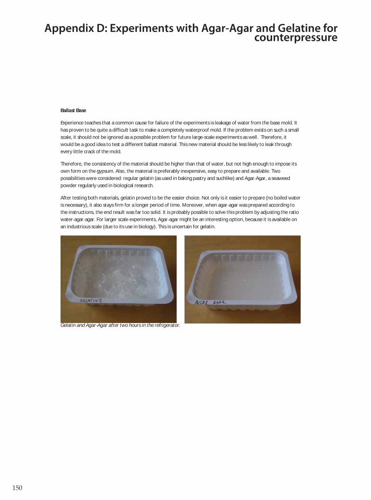
150
Appendix D: Experiments with Agar-Agar and Gelatine for counterpressure
Ballast Base
Experience teaches that a common cause for failure of the experiments is leakage of water from the base mold. Ithas proven to be quite a difficult task to make a completely waterproof mold. If the problem exists on such a smallscale, it should not be ignored as a possible problem for future large scale experiments as well. Therefore, itwould be a good idea to test a different ballast material. This new material should be less likely to leak throughevery little crack of the mold.
Therefore, the consistency of the material should be higher than that of water, but not high enough to impose itsown form on the gypsum. Also, the material is preferably inexpensive, easy to prepare and available. Twopossibilities were considered: regular gelatin (as used in baking pastry and suchlike) and Agar Agar, a seaweedpowder regularly used in biological research.
After testing both materials, gelatin proved to be the easier choice. Not only is it easier to prepare (no boiled wateris necessary), it also stays firm for a longer period of time. Moreover, when agar agar was prepared according tothe instructions, the end result was far too solid. It is probably possible to solve this problem by adjusting the ratiowater agar agar. For larger scale experiments, Agar agar might be an interesting option, because it is available onan industrious scale (due to its use in biology). This is uncertain for gelatin.
Gelatin and Agar Agar after two hours in the refrigerator.

151
Experiment AD
Goal: Make a segment using gelatin as base ballast.
Concrete: 810 ml gypsum (1,13 kg)
Ballast (base): 1550 ml gelatin (curvature 1)
Ballast (top): 2000 ml sand
There is no leakage whatsoever form the base mold. Some slight leakage of gypsum occurs, this stops after a shortperiod of time. No clamps were necessary to press the molds together.
Results:
Req. 1: surfaceThe surface quality of the underside is perfect.The surface quality of the upside is comparable to ex. V.
Req 2: continuity of form
Req. 3: Uniform thicknessThe segment does not seem to be of uniform thickness. Also, the segment is not symmetrical.
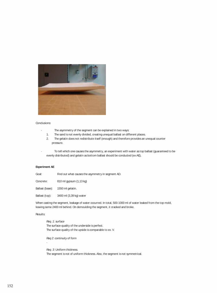
152
Conclusions:
The asymmetry of the segment can be explained in two ways:1. The sand is not evenly divided, creating unequal ballast on different places.2. The gelatin does not redistribute itself (enough) and therefore provides an unequal counter
pressure.
To tell which one causes the asymmetry, an experiment with water as top ballast (guaranteed to beevenly distributed) and gelatin as bottom ballast should be conducted (ex AE),
Experiment AE
Goal: Find out what causes the asymmetry in segment AD.
Concrete: 810 ml gypsum (1,13 kg)
Ballast (base): 1550 ml gelatin.
Ballast (top): 3400 ml (3,39 kg) water
When casting the segment, leakage of water occurred. In total, 500 1000 ml of water leaked from the top mold,leaving some 2400 ml behind. On demoulding the segment, it cracked and broke.
Results:
Req. 1: surfaceThe surface quality of the underside is perfect.The surface quality of the upside is comparable to ex. V.
Req 2: continuity of form
Req. 3: Uniform thickness.The segment is not of uniform thickness. Also, the segment is not symmetrical.

153
Conclusions:
Gelatin is not a usable replacement for water as bottom ballast.

154