franklin county development & construction …
TRANSCRIPT

FRANKLIN COUNTY DEVELOPMENT & CONSTRUCTION
STANDARDS MANUAL
CHAPTER 3 STORMWATER SPECIFICATIONS
TABLE OF CONTENTS
Section Subject Page
3.1 GENERAL 3-1
3.1.1 Permitting 3-13.1.2 References
3.2 DESIGN CRITERIA 3-2
3.2.1 Stormwater Control Policy 3-23.2.2 Definitions 3-33.2.3 Determination of Runoff Quantities 3-73.2.4 Amount of Runoff to be Accommodated by Various
Parts of the Drainage Facility 3-123.2.5 Storm Sewer Design Standards 3-133.2.6 Open Channel Design Standards 3-143.2.7 Construction and Materials 3-193.2.8 Stormwater Detention 3-213.2.9 Change in Plan 3-283.2.10 Determination of Impact Drainage Areas 3-283.2.11 Disclaimer of Liability 3-29
3.3 MATERIAL SPECIFICATIONS 3-29
3.3.1 Sewer Pipe 3-293.3.2 Pipe Materials 3-303.3.3 Manholes, Catch Basins and Inlets (Structures) 3-313.3.4 Joints, Fittings and Appurtenances 3-32
3.4 CONSTRUCTION REQUIREMENTS 3-32
3.4.1 Surface Conditions 3-323.4.2 Field Measurements, Surveys Lines, Reference Points
& Grades 3-333.4.3 Installation of Pipe 3-333.4.4 General Trenching 3-373.4.5 Removal of Material 3-38

Section Subject Page 3.4.6 Stabilization 3-38 3.4.7 Backfilling 3-38 3.4.8 Compaction Testing 3-40 3.4.9 Installation of Manholes, Catch Basins & Inlets (Structures) 3-41 3.4.10 Grade Adjustment of Existing Structures 3-43 3.4.11 Record Drawings 3-43
LIST OF TABLES
Table Page 3-1 Urban Runoff Coefficients 3-9 3-1a Rural Runoff Coefficients 3-10 3-2 Runoff Coefficients “C” by Land Use and Typical Inlet Times 3-11 3-3 Typical Values of Manning’s (n) Roughness Coefficient 3-16 3-4 Maximum Permissible Velocities in Vegetal-Lined Channels* 3-20 3-5 Rainfall Intensities for Various Return Periods and Storm Durations for Intensity (inches per hour) 3-23
LIST OF DRAWINGS
Title Drawing No. Flexible Sewer Pipe Bedding Detail (Class I & II) BB-1 Rigid Pipe Bedding Detail "Class A" BB-2 Rigid Pipe Bedding Detail "Class B" BB-3 Rigid Pipe Bedding Detail "Class C" BB-4 Backfill Requirements (within R/W for Improved Streets) BB-5 Backfill Requirements (For Crossing R/W for Improved Streets) BB-6 Metal Flared End Section M-1 Concrete Flared End Section M-2 Grass Swale M-3 INDOT Metal Pipe End Section E 715-MPES-01 INDOT Metal Pipe Arch End Section E 715-MPES-02 INDOT Metal Pipe End Section Connections E 715-MPES-03 INDOT Precast Concrete End Section E 715-PCES-01 INDOT Slotted Drain Pipe E 715-SLDR-01 INDOT Slotted Drain Pipe E 715-SLDR-02 INDOT Slotted Vane Drain Pipe E 715-SLDR-03 INDOT Pipe Catch Basin Casting E 720-CBCA-01 INDOT Catch Basin Type A E 720-CBST-01 INDOT Catch Basin Type D E 720-CBST-02 INDOT Catch Basin Type E E 720-CBST-03 INDOT Catch Basin Type J E 720-CBST-04 INDOT Catch Basin Type K E 720-CBST-05 INDOT Catch Basin Pipe E 720-CBST-06 INDOT Catch Basin Type S E 720-CBST-07

LIST OF DRAWINGS (cont'd)
Title Drawing No. INDOT Catch Basin Type W E 720-CBST-08 INDOT Catch Basin Hood E 720-CBST-09 INDOT Compatibility of Drainage Structures and Castings E 720-CDSC-01 INDOT Earth Ditch Casting Type 7 E 720-EDCA-01 INDOT Casting Type 5 Frame E 720-ICCA-01 INDOT Casting Type 5 Alternate Bolted Frame E 720-ICCA-02 INDOT Casting Type 5 (Alternate) Frame and Grate E 720-ICCA-03 INDOT Casting Type 8 Frame E 720-ICCA-04 INDOT Casting Type 8 Grate E 720-ICCA-05 INDOT Casting Type 8 Curb Box E 720-ICCA-06 INDOT Casting Type 10 Frame E 720-ICCA-08 INDOT Casting Type 10 Grate E 720-ICCA-09 INDOT Casting Type 10 Curb Box E 720-ICCA-09A INDOT Steel Grating Type 12 Frame and Grate E 720-ICCA-10 INDOT Casting Type 12 (Alternate) Frame and Grate E 720-ICCA-11 INDOT Steel Grating Type 12A Frame and Grate E 720-ICCA-12 INDOT Casting Type 13 Frame and Grate E 720-ICCA-13 INDOT Casting Type 14 Frame and Grate E 720-ICCA-15 INDOT Casting Type 15 Frame and Grate E 720-ICCA-16 INDOT Casting Type 15 Grate E 720-ICCA-17 INDOT Casting Type 15 Curb Box E 720-ICCA-18 INDOT Casting Type 15 (Alternate) Frame, Grate and Curb Box E 720-ICCA-19 INDOT Inlet Casting Type 6 E 720-INCA-01 INDOT Curb Inlet Casting Type 3 E 720-INCA-02 INDOT Inlet Type A E 720-INST-01 INDOT Inlets Type B and C E 720-INST-02 INDOT Inlet Type D E 720-INST-03 INDOT Inlets Type E and F E 720-INST-04 INDOT Inlet Type G E 720-INST-05 INDOT Inlet Type J E 720-INST-06 INDOT Inlets Type M and R E 720-INST-07 INDOT Inlet Type N E 720-INST-08 INDOT Inlet Type P E 720-INST-09 INDOT Inlets Type S and T E 720-INST-10 INDOT Flat Top Grate Casting Type 2 E 720-MHCA-01 INDOT Manhole Casting Type 4 Ring and Cover E 720-MHCA-02 INDOT Manhole Casting Type 4 Alternate Cover E 720-MHCA-03 INDOT Manholes Type A and B E 720-MHST-01 INDOT Manhole Type C E 720-MHST-02 INDOT Manholes Drop Manhole Type C E 720-MHST-03 INDOT Manholes Type D, E, F and G E 720-MHST-04 INDOT Manholes Type H, J, K, L, M and N E 720-MHST-05 INDOT Precast Concrete Manhole Sections E 720-MHST-06 INDOT Precast Concrete Manhole Bottom Section E 720-MHST-07 INDOT Manhole Bars and Concentric Cone E 720-MHST-08 INDOT Manhole Step E 720-MHST-09 INDOT Table of Reinforcing Steel for Manholes E 720-MHST-10 INDOT Slotted Drain Pipe Cleanout Port E 720-SDCP-01

LIST OF DRAWINGS (cont'd)
Title Drawing No. INDOT Casting Type I Frame and Grate E 720-SDCP-02 INDOT Casting Type II Frame and Grate E 720-SDCP-03

CHAPTER 3 STORMWATER SPECIFICATIONS
3-1
FRANKLIN COUNTY DEVELOPMENT &
CONSTRUCTION STANDARDS MANUAL
SECTION 3.1: GENERAL
3.1.1 Permitting shall be per the requirements of Chapter 6.
3.1.2 References
A. AASHTO M170 - Reinforced Concrete Culvert, Storm Drain, and Sewer Pipe
B. AASHTO M294 - Corrugated Polyethylene Pipe, 300 to 1200 mm Diameter
C. ASTM A48 - Standard Specification for Gray Iron Castings
D. ASTM A536 - Standard Specification for Ductile Iron Castings
E. ASTM C76 - Standard Specification for Reinforced Concrete Culvert, StormDrain, and Sewer Pipe
F. ASTM C361 - Standard Specification for Reinforced Concrete Low-HeadPressure Pipe
G. ASTM C443 - Standard Specification for Joints for Concrete Pipe andManholes, Using Rubber Gaskets
H. ASTM C478 - Standard Specification for Precast Reinforced ConcreteManhole Sections
I. ASTM D1556 - Standard Test Method for Density and Unit Weight of Soil inPlace by the Sand-Cone Method
J. ASTM D1782 - Standard Test Methods for Operating Performance ofParticulate Cation-Exchange Materials
K. ASTM D2167 - Standard Test Method for Density and Unit Weight of Soil inPlace by the Rubber Balloon Method
L. ASTM D2321 - Standard Practice for Underground Installation ofThermoplastic Pipe for Sewers and Other Gravity-Flow Applications
M. ASTM D2922 - Standard Test Methods for Density of Soil and Soil-Aggregatein Place by Nuclear Methods (Shallow Depth)
N. ASTM D3017 - Standard Test Method for Water Content of Soil and Rock inPlace by Nuclear Methods (Shallow Depth)
O. ASTM D3034 - Standard Specification for Type PSM Poly(Vinyl Chloride)(PVC) Sewer Pipe and Fittings.
P. ASTM D3212 - Standard Specification for Joints for Drain and Sewer Plastic
xxxxxxxxxxxxxxxxxxxxxxxxxxxxxxxxxxxxxxxxxxxxxxxx per Commissioners strike 3.1.1

CHAPTER 3 STORMWATER SPECIFICATIONS
3-2
FRANKLIN COUNTY DEVELOPMENT &
CONSTRUCTION STANDARDS MANUAL
Pipes Using Flexible Elastomeric Seals
Q. ASTM F477 - Standard Specification for Elastomeric Seals (Gaskets) forJoining Plastic Pipe
R. ASTM F679 - Standard Specification for Poly(Vinyl Chloride) (PVC) Large-Diameter Plastic Gravity Sewer Pipe and Fittings
S. ASTM F794 - Standard Specification for Poly(Vinyl Chloride) (PVC) ProfileGravity Sewer Pipe and Fittings Based on Controlled Inside Diameter
T. ILLUDAS - Terstriep, M.L., and J.B. Stall, The Illinois Urban Drainage AreaSimulator, Bulletin 58, Illinois State Water Survey, Urbana, 1974
U. Indiana Design Manual - Published by the Indiana Department ofTransportation
V. TR-20 -Technical Release 20 Computer Program for Project FormulationHydrology, Natural Resource Conservation Service, 1992
W. TR-55 - Technical Release 55 Urban Hydrology for Small Watersheds,Natural Resource Conservation Service, 1986
SECTION 3.2 DESIGN CRITERIA
3.2.1 STORMWATER CONTROL POLICY
It is recognized that the smaller streams and drainage channels serving Franklin County may not have sufficient capacity to receive and convey stormwater runoff resulting from continued urbanization. Accordingly, the storage and controlled release rate may be required for any development, redevelopment, and new construction located within the County.
Possible exceptions to the requirements are divisions of land per section 80.09 of Franklin County Zoning Ordinance. The County, after thorough investigation and evaluation, may waive the requirements of controlled runoff for multiple divisions of an existing parcel creating new tracts greater than 2 acres, not requiring a shared private lane or new public road dedication.
The release rate of stormwater from development, redevelopment, and new construction may not exceed the stormwater runoff from the land area in its present state of development. The developer must submit to the County detailed computations of runoff before and after development, redevelopment, or new construction, which demonstrate that runoff will not be increased.
These computations must show that the peak runoff rate after development for the 100-year return period storm of critical duration must not exceed the 10-year return period pre-development peak runoff rate. The critical duration storm is

CHAPTER 3 STORMWATER SPECIFICATIONS
3-3
FRANKLIN COUNTY DEVELOPMENT &
CONSTRUCTION STANDARDS MANUAL
that storm duration that requires the greatest detention storage.
Computations for areas up to and including 200 acres may be based on the Rational Method; typical runoff coefficients are listed herein. For areas larger than 200 acres, hydrograph techniques and/or computer drainage modeling methods may be used. Hydrograph techniques and computer modeling methods used to determine stormwater runoff shall be proven methods, subject to approval of the County.
The County, or other governmental unit will not accept any responsibility for liability and maintenance of detention/retention facilities.
3.2.2 DEFINITIONS
For the purpose of this chapter, the following definitions shall apply:
A. Capacity of a storm drainage facility: the maximum flow that can be conveyedor stored by a storm drainage facility without causing damage to public orprivate property.
B. Channel: a natural or artificial watercourse which periodically or continuouslycontains moving water, or which forms a connecting link between two bodiesof water. It has a defined bed and banks which serve to confine the water.
C. County: Franklin County, Indiana. Also any employee or representative towhom they shall specifically delegate this responsibility.
D. Compensatory Storage: an artificial volume of storage within a floodplain used to balance the loss of natural flood storage capacity when artificialfill or structures are placed within the flood plain.
E. Contiguous: adjoining or in actual contact with.
F. Critical Duration Storm: The storm duration that requires the greatestdetention storage for a given return period.
G. Culvert: a closed conduit used for the passage of surface drainage waterunder a roadway, railroad canal, or other impediment.
H. Dam: an earthen, concrete, or other material constructed to hold back orcontrol the level of water.
I. Detention Basin: a facility constructed or modified to restrict the flow ofstormwater to a prescribed maximum rate, and to detain concurrently theexcess waters that accumulate behind the outlet.
J. Detention Storage: the temporary detaining or storage of stormwater instorage basins, on rooftops, in streets, parking lots, school yards, parks,

CHAPTER 3 STORMWATER SPECIFICATIONS
3-4
FRANKLIN COUNTY DEVELOPMENT &
CONSTRUCTION STANDARDS MANUAL
open spaces, or other areas under predetermined and controlled conditions, with the rate of drainage therefrom regulated by appropriately installed devices.
K. Drainage Area: the area from which water is carried off by a drainagesystem; a watershed, or catchment area.
L. Drop Manhole: a manhole having a vertical drop pipe connecting the inletpipe to the outlet pipe. The vertical drop pipe shall be located immediatelyoutside the manhole. Inside drop pipes may be allowed under specialcircumstances and only with prior approval.
M. Dry Bottom Detention Basin: a basin designed to be completely dewateredafter having provided its planned detention of runoff during a storm event.
N. Duration: the time period of a rainfall event.
O. Erosion: wearing away of the land by running water, waves, temperaturechanges, ice, or wind.
P. Flood Elevation: the elevation at all locations delineating the maximum levelof high waters for a flood of given return period and rainfall duration.
Q. Flood or Flood Waters: the water of any watercourse which is above thebanks of the watercourse.
R. Flood Hazard Area: any flood plain, floodway, floodway fringe, or anycombination thereof which is subject to inundation by the regulatory flood; orany flood plain as delineated by Zone A on a FEMA Flood Hazard BoundaryMap.
S. Flood Plain: the area adjoining the river or stream which had been or mayhereafter be covered by floodwaters.
T. Flood Protection Grade: the elevation of the lowest floor of a building. If abasement is included, the basement floor is considered the lowest floor.
U. Floodway: SEE Regulatory Flood.
V. Floodway Fringe: that portion of the flood plain lying outside the floodway,which is inundated by the regulatory flood.
W. Footing Drain: a drain pipe installed around the exterior of a basement wallfoundation to relieve water pressure caused by high groundwater elevation.
X. Grade: the inclination or slope of a channel, canal, conduit, etc., or naturalground surface usually expressed in terms of the percentage the vertical rise(or fall) bears to the corresponding horizontal distance.

CHAPTER 3 STORMWATER SPECIFICATIONS
3-5
FRANKLIN COUNTY DEVELOPMENT &
CONSTRUCTION STANDARDS MANUAL
Y. Impact Areas: areas defined and mapped by the County which are unlikely tobe easily drained because of one or more factors.
Z. Impervious: a term applied to material through which water cannot pass, orthrough which water passes with difficulty.
AA. Inlet: an opening into a storm sewer system for the entrance of surface stormwater runoff, more completely described as a storm sewer inlet.
BB. Junction Chamber: a converging section of conduit, usually large enough for a person to enter, used to facilitate the flow from one or more conduits into a main conduit.
CC. Lateral Storm Sewer: a sewer that has inlets connected to it but has noother storm sewer connected.
DD. Manhole: storm sewer structure through which a person may enter to gainaccess to an underground storm sewer or enclosed structure.
EE. Major Drainage System: drainage system carrying runoff from an area of one or more square miles.
FF. Minor Drainage System: drainage system having an area of less than one square mile.
GG. Off-Site: everything not on site.
HH. On-Site: located within the controlled area where runoff originates.
II. Outfall: the point or location where storm runoff discharges from a seweror drain. Also applied to the outfall sewer or channel which carries thestorm runoff to the point or outfall.
JJ. Peak Flow: the maximum rate of flow of water at a given point in a channel or conduit resulting from a particular storm or flood.
KK. Radius of Curvature: length of radius of a circle used to define a curve.
LL.. Rainfall Intensity: the cumulative depth of rainfall occurring over a given duration, normally expressed in inches per hour.
MM. Reach: any length of river, channel, or storm sewer.
NN. Regulated Area: all of the land under the jurisdiction of Franklin County
OO. Regulatory Flood: that flood having a peak discharge which can be

CHAPTER 3 STORMWATER SPECIFICATIONS
3-6
FRANKLIN COUNTY DEVELOPMENT &
CONSTRUCTION STANDARDS MANUAL
equaled to exceed on the average of once in a one hundred (100) year period, as calculated by a method and procedure which is acceptable to the County. If a permit from the Natural Resources Commission for construction in the floodway is required (see Section VI), then the regulatory flood peak discharge should be calculated by a method acceptable to the County and the Natural Resources Commission. This regulatory flood is equivalent to a flood having a probability of occurrence of one percent (1%) in any given year.
PP. Regulatory Floodway: the channel of a river or stream and those portions of the flood plains adjoining the channel which are reasonably required to carry and discharge the peak flow of the regulatory flood of any river or stream.
QQ. Release Rate: the amount of stormwater released from a stormwater control facility per unit of time.
RR. Return Period: the average interval of time within which a given rainfall event will be equaled or exceeded once. A flood having a return period of 100 years has a one percent probability of being equal to or exceeded in any one year.
SS. Runoff Coefficient: a decimal fraction relating the amount of rain which appears as runoff and reaches the storm drainage system to the total amount of rain falling. A coefficient of 0.5 implies that 50 percent of the rain falling on a given surface appears as stormwater runoff.
TT. Sediment: material of soil and rock origin, transported, carried, or deposited by water.
U.U. Siphon: a closed conduit or portion of which lies above the hydraulic grade line, resulting in a pressure less than atmospheric and requiring a vacuum within the conduit to start flow. A siphon utilizes atmospheric pressure to effect or increase the flow of water through a conduit.
An inverted siphon is a closed conduit used to carry stormwater flow that dips below the hydraulic grade line to avoid an obstruction such as a sanitary sewer, water main, etc.
VV. Spillway: a waterway in or about a hydraulic structure, for the escape of excess water.
WW. Stilling Basin: a basin used to slow water down or dissipate its energy.
XX. Storage Duration: the length of time that water may be stored in anystormwater control facility, computed from the time water first begins to bestored.

CHAPTER 3 STORMWATER SPECIFICATIONS
3-7
FRANKLIN COUNTY DEVELOPMENT &
CONSTRUCTION STANDARDS MANUAL
YY. Storm Sewer: a closed conduit for conveying collected stormwater.
ZZ. Stormwater Drainage System: all means, natural or man-made, used for conducting stormwater to, through, and from a drainage area to any of the following: conduits and appurtenant features, canals, channels, ditches, streams, culverts, streets, and pumping stations.
AAA. Stormwater Runoff: the water derived from rains falling within a tributary basin, flowing over the surface of the ground or collected in channels or conduits.
BBB. Tributary: contributing stormwater from upstream land areas.
CCC. Urbanization: the development, change, or improvement of any parcel ofland consisting of one or more lots for residential, commercial, industrial,recreational, or public utility purposes.
DDD. Watercourse: any river, stream, brook, branch, natural or man-made,drainageway in or into which stormwater runoff or floodwaters flow eitherregularly or intermittently.
EEE. Watershed: SEE Drainage Area.
FFF. Wet Bottom Detention Area (Retention Basin): a basin designed to retain a permanent pool of water after having provided its planned detention of runoff during a storm event.
3.2.3 DETERMINATION OF RUNOFF QUANTITIES
Runoff quantities shall be computed for the area of the parcel under development, plus the area of the watershed flowing into the parcel under development. The quantity of runoff which is generated as a result of a given rainfall intensity may be calculated as follows:
A. For areas up to and including 200 acres, the Rational Method may be used.In the Rational Method, the peak rate of runoff Q, in cubic feet per second, iscomputed as:
Q = CIAWhere:C = runoff coefficient, representing the characteristics of the drainage areaand defined as the ratio of runoff to rainfall.
I = average intensity of rainfall in inches per hour for a duration equal to the time of concentration (tc) for a selected rainfall frequency. A = tributary drainage area in acres.
Guidance to selection of the runoff coefficient “C” is provided by Table 3-1

CHAPTER 3 STORMWATER SPECIFICATIONS
3-8
FRANKLIN COUNTY DEVELOPMENT &
CONSTRUCTION STANDARDS MANUAL
and Table 3-1A that show values for different types of surface and local soil characteristics. The composite “C” value used for a given drainage area with various surface types shall be the weighted average for the total area calculated from a breakdown of individual areas having different surface types.
Table 3-2 provides runoff coefficients and inlet times for different land uses situated in an upstream area. A coefficient or coefficients shall be used for this area in its present or existing state of development.
Rainfall Intensity shall be determined from the rainfall data shown in Table 3-5. The time of concentration (tc) to be used shall be the sum of the inlet timeand flow time in the drainage facility under consideration. The flow time in thestorm sewers may be estimated by the distance in feet divided by velocity offlow in feet per second. The velocity shall be determined using the ManningFormula.
Inlet time is the combined time required for the runoff to reach the inlet of the storm sewer. It includes overland flow time and flow time through established surface drainage channels such as swales, ditches, and sheet flow across such areas as lawns, fields, and other graded surfaces.
B. The runoff rate for areas in excess of 200 acres shall be determined bymethods described in 3.2.6, Subsection F.

CHAPTER 3 STORMWATER SPECIFICATIONS
3-9
FRANKLIN COUNTY DEVELOPMENT &
CONSTRUCTION STANDARDS MANUAL
TABLE 3-1
Urban Runoff Coefficients
Type of Surface Runoff Coefficient “C”
Asphalt 0.82
Concrete 0.85
Roof 0.85
Lawns (Sandy) Flat (0-2% slope) Rolling (2-7% slope) Steep (>7% slope)
0.07 0.12 0.17
Lawns (Clay) Flat (0-2% slope) Rolling (2-7% slope) Steep (>7% slope)
0.16 0.21 0.30
The coefficients of this tabulation are applicable to storms of 5- to 10-year frequencies. Coefficients for less frequent, higher intensity storms shall be modified as follows with a maximum “C” factor of 1.0:
Return Period (years) Multiply “C” by
25 1.1
50 1.2
100 1.25

CHAPTER 3 STORMWATER SPECIFICATIONS
3-10
FRANKLIN COUNTY DEVELOPMENT &
CONSTRUCTION STANDARDS MANUAL
TABLE 3-1A
Rural Runoff Coefficients
Type of Surface Runoff Coefficient “C”
Woodland (Sandy) Flat (0-5% slope) Rolling (5-10% slope) Steep (>10% slope)
0.10 0.25 0.30
Woodland (Clay) Flat Rolling Steep
0.30 0.35 0.50
Pasture (Sandy) Flat Rolling Steep
0.10 0.16 0.22
Pasture (Clay) Flat Rolling Steep
0.30 0.36 0.42
Cultivated (Sandy) Flat Rolling Steep
0.30 0.40 0.52
Cultivated (Clay) Flat Rolling Steep
0.50 0.60 0.72
The coefficients of this tabulation are applicable to storms of 5- to 10-year frequencies. Coefficients for less frequent, higher intensity storms shall be modified as follows with a maximum “C” factor of 1.0:
Return Period (years) Multiply “C” by
25 1.1
50 1.2
100 1.25

CHAPTER 3 STORMWATER SPECIFICATIONS
3-11
FRANKLIN COUNTY DEVELOPMENT &
CONSTRUCTION STANDARDS MANUAL
TABLE 3-2
Runoff Coefficients “C” by Land Use and Typical Inlet Times
LAND USE RUNOFF COEFFICIENTS INLET TIME (minutes)
FLAT ROLLING STEEP
Commercial (CBD) 0.75 0.83 0.91 5
Commercial (NHD) 0.54 0.60 0.66 5
Industrial 0.63 0.70 0.77 5-10
Garden Apartments 0.54 0.60 0.66 5-10
Churches 0.54 0.60 0.66 5-10
Schools 0.31 0.35 0.39 10-15
Semi-Detached Residence 0.45 0.50 0.55 10-15
Detached Residence 0.40 0.45 0.50 10-15
Quarter-Acre Lots 0.36 0.40 0.44 10-15
Half-Acre Lots 0.31 0.35 0.39 10-15
Parkland 0.18 0.20 0.22 To be determined
1. Flat Terrain = 0-2% slopes2. Rolling Terrain = 2-7% slopes3. Steep Terrain = 7% 4. Interpolation, extrapolation, and adjustment for local conditions shall be
based on engineering experience and judgment.5. The coefficients of this tabulation are applicable to storms of 5- to 10-year
frequencies. Coefficients for less frequent, higher intensity storms shall bemodified as follows with a maximum “C” factor of 1.0:
Return Period (years) Multiply “C” by
25 1.1
50 1.2
100 1.25

CHAPTER 3 STORMWATER SPECIFICATIONS
3-12
FRANKLIN COUNTY DEVELOPMENT &
CONSTRUCTION STANDARDS MANUAL
3.2.4 AMOUNT OF RUNOFF TO BE ACCOMMODATED BY VARIOUS PARTS OF A DRAINAGE FACILITY
Various parts of a drainage facility must accommodate runoff water as follows:
A. The minor drainage system such as inlets, catch basins, street gutters,swales, sewers, and small channels which collect stormwater mustaccommodate peak runoff from a 10-year return period storm. Rainfallduration shall be equal to the time of concentration or one hour, if the time ofthe concentration is less than one hour. A first quartile storm distribution shallbe used for computer modeling. These minimum requirements must besatisfied:
1. The allowable spread of water on collector streets is limited tomaintaining two clear 10-foot moving lanes of traffic. One lane is to bemaintained on local roads, while places can have a water spread equalto one-half of their width.
2. Open channels carrying peak flows greater than 30 cubic feet persecond shall be capable of accommodating peak runoff for a 50-yearreturn period storm within the drainage easement.
3. Culverts shall be capable of accommodating peak runoff from a 50-yearreturn period storm when crossing under a road which is part of theIndiana Department of Transportation rural functional classificationsystem and are classified as principal or minor arterial, major, or minorcollector roads.
B. Major drainage systems are defined as 3.2.2.EE, and shall be designed inaccordance with Indiana Department of Natural Resources standards asdescribed in Section 3.2.4.C.
C. Chapter 318 of the Acts of 1945, as amended, Sections 17 and 19, requirethe Natural Resources Commission approval of any construction in afloodway, and of any works for flood control. This includes bridges, dams,levees, floodwalls, wharves, piers, booms, weirs, bulkheads, jetties, groins,excavations, fills, or deposits of any kind, utility lies, or any other building,structure, or obstruction. Also, any ditch work (new construction, deepeningor modification) within one-half mile of a public freshwater lake of 10 acres ormore in area.
The approval of the Natural Resources Commission, in writing, must beobtained before beginning construction. Applications for approval should besubmitted to:

CHAPTER 3 STORMWATER SPECIFICATIONS
3-13
FRANKLIN COUNTY DEVELOPMENT &
CONSTRUCTION STANDARDS MANUAL
Indiana Department of Natural Resources Division of Water
402 West Washington St., Room W264 Indianapolis IN 46204
All applications should be made on the standard application form provided by the Commission and should be accompanied by plans, profiles, specifications, and other data necessary for the Commission to determine the effect of the proposed construction upon the floodway and on flood control in the state.
Application made to and approval granted by the Natural Resources Commission does not in any way relieve the owner of the necessity of securing easements or other property rights, and permits and/or approvals from affected property owners and local, state, and federal agencies.
The engineering staff of the Division of Water is available to discuss and offer suggestions regarding requirements in the design of structures in floodways. High water marks have been set on many of the streams in the state, and information is available from the Division of Water on actual and/or potential flooding. Information regarding benchmarks set to Mean Sea Level Datum, General Adjustment of 1929, is available from the Division of Water, Surveying, and Mapping Section.
Applications are considered by the Commission at regular meetings usually held each month. After the application and plans have been approved by the Commission, a certificate of approval is forwarded to the applicant.
A fee is charged by the Commission for approval under the Flood Control Act unless stated otherwise in the Approval. Construction is considered to be a permanent development, and no renewals of the approval are necessary except in the cases where temporary approvals are granted for temporary construction. The right is reserved to require additional data where necessary.
3.2.5 STORM SEWER DESIGN STANDARDS
All storm sewers, whether private or public, and whether constructed on private or public property, shall conform to the design standards and other requirements contained herein.
A. Manning Equation - The hydraulic capacity of sewers shall be determinedusing the Manning’s Equation: v = (1.486/n) R 2/3 S 1/2. Where:
v = mean velocity in feet per second R = the hydraulic radius in feet S = the slope of the energy grade line in feet per foot n = the roughness coefficient

CHAPTER 3 STORMWATER SPECIFICATIONS
3-14
FRANKLIN COUNTY INDIANA DEVELOPMENT &
CONSTRUCTION STANDARDS MANUAL
The hydraulic radius, R, is defined as the cross-sectional area divided by the wetted flow surface or wetted perimeter. Typical “n” values and maximum permissible velocities for storm sewer materials are listed in Table 3-3. Roughness coefficient (n) values for other sewer materials can be found in standard hydraulics texts and references.
B. Minimum Size - The minimum size of all storm sewers shall be 12 inches.The rate of release for detention storage shall be controlled by an orificeplate or other devices, subject to the approval of the County, where the 12-inch pipe will not limit the rate of release as required.
C. Grade - Sewer grade shall be such that, in general, a minimum of two feet ofcover is maintained over the top of the pipe. Pipe cover less than minimummay be used only upon approval of the County. Uniform slopes shallbe maintained between inlets, manholes, and inlets to manholes. Finalgrade shall be set with the full consideration of the capacity required,sedimentation problems, and other design parameters. Minimum andmaximum allowable slopes shall be those capable of producing velocities oftwo and one-half and fifteen feet per second, respectively, when the seweris full flowing.
D. Alignment - Storm sewers shall be straight between manholes wheneverpossible. Where long radius curves are necessary to conform to street layout,the minimum radius of curvature shall be no less than one hundred feet forsewers forty-two inches and larger in diameter. Deflection of pipe sectionsshall not exceed the maximum deflection recommended by the pipemanufacturer. The deflection shall be uniform, and finished installation shallfollow a smooth curve.
E. Manholes - Manholes shall be installed to provide access to continuousunderground storm sewers for the purpose of inspection and maintenance.Manholes shall be provided at the following locations:
1. where two or more storm sewers converge
2. at the point of beginning or at the end of a curve, and at the point ofreverse curvature (PC, PT, PRC)
3. where pipe size changes
4. where an abrupt change in alignment occurs
5. where a change in grade occurs
6. at suitable intervals in straight sections of sewer; the maximum distancebetween storm sewer manholes shall be as follows:

CHAPTER 3 STORMWATER SPECIFICATIONS
3-15
FRANKLIN COUNTY DEVELOPMENT &
CONSTRUCTION STANDARDS MANUAL
Size of Pipe (Inches) Maximum Distance (feet)
12 through 42 400 48 and larger 600
F. Inlets - Inlets or drainage structures shall be utilized to collect surface waterthrough grated openings and convey it to storm sewers, channels, orculverts. Inlet design and spacing shall be in accordance with Chapter 36,Section 10 of the Indiana Design Manual or other approved designprocedure. The inlet grate opening provided must be adequate to pass thedesign 10-year flood with 50% of the sag inlet areas clogged. An overloadedchannel from the sag inlets to the overflow channel or basin shall be providedat sag inlets, so that the maximum depth of water that might be ponded in thestreet sag shall not exceed 7 inches.

CHAPTER 3 STORMWATER SPECIFICATIONS
3-16
FRANKLIN COUNTY INDIANA DEVELOPMENT &
CONSTRUCTION STANDARDS MANUAL
TABLE 3-3
Typical Values of Manning’s (n) Roughness Coefficient
MATERIAL MANNING’S (n) DESIRABLE MAX. VELOCITIES
Closed Conduits Concrete PVC Ductile Iron
0.013 0.011 0.013
15 fps 15 fps 15 fps
Circular Corrugated Metal, Annular Corrugations (2 2/3" x 1/2")
Unpaved 25% Paved 50% Paved 100% Paved
See Below 0.021 0.018 0.013
7 fps 7 fps 7 fps 7 fps
C.C.M.P., Helical Corrugations, 2 2/3" x1/2" Unpaved Corrugation
12" 18" 24" 36" 48" 60" or larger
0.022 0.023 0.024 0.025 0.026 0.027
7 fps 7 fps 7 fps 7 fps 7 fps
Corrugated polyethylene smooth interior pipe, HDPE 0.012 15 fps
Open Channels Concrete, trowel finish Concrete, broom float Gunite Riprap, placed Riprap, dumped Gabion New earth (unif. sod clay) Existing earth (fairly uniform, some weeds) Dense growth of weeds Dense weeds and brush Swale with grass
0.013 0.015 0.018 0.030 0.035 0.028 0.025
0.030 0.040 0.040 0.035
See Table 3-4 for all open channel velocities
3.2.6 OPEN CHANNEL DESIGN STANDARDS
All open channels, whether private or public, and whether constructed on private or public land, shall conform to the design standards and other design requirements contained herein.

CHAPTER 3 STORMWATER SPECIFICATIONS
3-17
FRANKLIN COUNTY INDIANA DEVELOPMENT &
CONSTRUCTION STANDARDS MANUAL
A. Manning’s EquationThe waterway for channels shall be determined using Manning’s Equation.
Q = AV = A(1.486/n) R2/3 S1/2 Where:
A = waterway area of channel in square feet Q = discharge in cubic feet per second (cfs) V,R,S, & n = are explained in paragraph 3.2.5-A.
B. Channel Cross-Section and GradeThe required channel cross-section and grade are determined by the designcapacity. A minimum depth may be required to provide adequate outlets forsubsurface drains, tributary ditches, or streams. The channel grade shall besuch that the velocity in the channel is high enough to prevent siltation totake place and ultimately reduce the channel cross-section. The maximumpermissible velocities in vegetal-lined channels to be constructed must beconsidered in design of the channel section.
C. Side SlopesEarthen channel side slopes shall be no steeper than 2 to 1. Flatter slopesmay be required to prevent erosion and for ease of maintenance. Wherechannels will be lined, side slopes shall be no steeper than 1 ½ to 1 withadequate provisions made for weep holes. Side slopes steeper than 1 ½ to 1may be used for lined channels, provided that the side lining and structuralretaining wall are designed and constructed with provisions for live and deadload surcharge.
D. Channel Stability1. Characteristics of a stable channel are:
a. it neither aggrades nor degrades beyond tolerable limitsb. the channel banks to not erode to the extent that the channel cross-
section changes appreciablyc. excessive sediment bars do not developd. excessive erosion does not occur around culverts, bridges, or
elsewheree. gullies do not form or enlarge due to the entry of uncontrolled
surface flow to the channel
2. Channel stability shall be determined for an aged condition, and thevelocity shall be based on the design flow or the bank full flow, whicheveris greater, using “n” values for various channel linings as shown in Table3-3. In no case, is it necessary to check channel stability for dischargesgreater than that from a 100-year return period storm.
3. Channel stability must be checked for conditions immediately afterconstruction. For this stability analysis, the velocity shall be calculatedfor the expected flow from a 10-year return period storm on thewatershed, or the bank full flow, whichever is smaller. The “n” value for

CHAPTER 3 STORMWATER SPECIFICATIONS
3-18
FRANKLIN COUNTYINDIANA DEVELOPMENT &
CONSTRUCTION STANDARDS MANUAL
newly constructed channels in fine-grained soils and sands may be determined in accordance with the National Engineering Handbook Section 5, Supplement B, Natural Resources Conservation Service, and shall not exceed channel 0.025.
4. The allowable velocities for newly constructed channels are shown onTable 3-4. Those velocities may be increased by a maximum of 20percent to reflect the effects of vegetation to be established under thefollowing conditions:a. the soil and site in which the channel is to be constructed are
suitable for rapid establishment and support of erosion-controllingvegetation
b. species of erosion-controlling vegetation adapted to the area andproven methods of establishment are shown
c. the channel design includes detailed plans for establishment ofvegetation on the channel side slopes.
E. Drainage of WaterwaysVegetated waterways that are subject to low flows of long duration or wherewet conditions prevail shall be drained with a tile system or by other meanssuch as paved gutters. Tile lines may be outletted through a standard tileoutlet.
F. Appurtenant StructuresThe design of channels will provide all structures required for the properfunctioning of the channel and the laterals thereto and travelways foroperation and maintenance. Recessed inlets and structures needed for entryof surface and subsurface flow into channels without significant erosion ordegradation shall be included in the design of channel improvements. Thedesign is also to provide the necessary flood gates, water level controldevices, and any other appurtenance affecting the functioning of thechannels and attainment of the purpose for which they are built.
The effect of channel improvements on existing culverts, bridges, buriedcables, pipelines, and inlet structures for surface and subsurface drainage onthe channel being improved and laterals thereto shall be evaluated todetermine the need for modification or replacement. Culverts and bridgeswhich are modified or added as part of channel improvement projects shallmeet reasonable standards for the type of structure, and shall have aminimum capacity equal to the design discharge or governmental agencydesign requirements, whichever is greater.
G. Disposition of SpoilsSpoil material resulting from clearing, grubbing, and channel excavation shallbe disposed of in such a manner which will:1. Minimize overbank wash2. Provide for the free flow of water between the channel and flood plain
unless the valley routing and water surface profile are based on

CHAPTER 3 STORMWATER SPECIFICATIONS
3-19
FRANKLIN COUNTY INDIANA DEVELOPMENT &
CONSTRUCTION STANDARDS MANUAL
continuous dikes being installed. 3. Not hinder the development of travelways for maintenance.4. Leave the right-of-way in the best condition feasible, consistent with the
project purposes for productive use by the owner.5. Improve the aesthetic appearance of the site to the extent feasible.5. Be approved by the IDNR or U.S. Army Corps of Engineers
(whichever is applicable), if deposited in floodway.
3.2.7 CONSTRUCTION AND MATERIALS
A. Construction - Specifications shall be in keeping with the current standards ofengineering practice and shall describe the requirements for the properinstallation of the project to achieve its intended purpose.
B. Materials - Materials acceptable for use as channel lining are:1. Grass2. Revetment riprap3. Concrete4. Hand-laid riprap5. Pre-cast cement concrete riprap6. Grouted riprap7. Gabions8. Other materials as approved by the County

CHAPTER 3 STORMWATER SPECIFICATIONS
3-20
FRANKLIN COUNTY INDIANA DEVELOPMENT &
CONSTRUCTION STANDARDS MANUAL
TABLE 3-4 Maximum Permissible Velocities in Vegetal-Lined Channels*
Permissible Velocity1
Cover Slope Range % Erosion Resist. Soils (fps)
Easily Eroded Soils (fps)
1. Bermuda Grass 0 - 5 5 - 10 > 10
8 7 6
6 5 4
2. BahiaBuffalo GrassKentucky BluegrassSmooth BromeBlue Grama
0 - 5 5 - 10 > 10
7 6 5
5 4 3
3. Grass Mixtures2
Reed Canary Grass0 - 5 5 - 10
5 4
4 3
4. Lespediza sericeaWeeping Lovegrass3
Yellow BluestemRed topAlfalfaRed Fescue
0 - 5 3.4 2.5
5. Common Lespediza4,5
Sudan Grass4 0 - 5 3.5 2.5
1 Use velocities exceeding 5 fps only where good cover and proper maintenance can be obtained
2 Do not use on slopes steeper than 10%, except for vegetated side slopes in combination with stone, concrete, or highly resistant vegetative center section.
3 Do not use on slopes steeper than 5% except for vegetated side slopes in combination with stone, concrete, or highly resistant vegetative center section.
4 Annuals: use on mild slopes or as temporary protection until permanent covers are established.
5 Use on slopes steeper than 5% is not recommended.
*Soil Conservation Service, SCS-TP-61, Handbook of Channel Design for Soil and WaterConservation.
Other lining materials shall receive specific approval of the County. Materials shall comply with those in the latest edition of INDOT’s Standard Specifications.

CHAPTER 3 STORMWATER SPECIFICATIONS
FRANKLIN COUNTY INDIANA DEVELOPMENT &
CONSTRUCTION STANDARDS MANUAL
3.2.8 STORMWATER DETENTION
The following shall govern the design of any improvement with respect to the detention of stormwater runoff.
A. Acceptable Detention MethodsThe increased stormwater runoff resulting from a proposed developmentshould be detained on-site by the provisions of appropriate wet or dry bottomreservoirs, by storage on flat roofs, parking lots, streets, lawns, or otheracceptable techniques. Measures which retard the rate of overland flow andvelocity in runoff channels shall also be used to partially control the runoffrate. Detention basins shall be sized to store excess flows from storms witha 100-year return period. Control devices shall limit the discharge to a rateno greater than that prescribed by 3.2.8.E. and F.
B. Design StormDesign of stormwater detention facilities shall be based on a return period ofonce in one hundred (100) years. The storage volume and outflow rate shallbe sufficient to handle stormwater runoff from a critical duration storm, asdefined in 3.2.8.E. and F.Rainfall intensity-duration-frequency relationships shall be those given inTables 3-5.
C. Allowable Release RateThe allowable release rate of stormwater originating from a proposeddevelopment shall not exceed the amount specified in 3.2.1., StormwaterControl Policy, and as described in 3.2.8.E. and F.In the event the natural downstream channel or storm sewer system isinadequate to accommodate the release rate provided above, then theallowable release rate shall be reduced to that rate permitted by the capacityof the receiving downstream channel or storm sewer system; and additionaldetention as determined by the County shall be required to store thatportion of the runoff exceeding the capacity of the receiving sewers orwaterways. If more than one detention basin is involved in the developmentof the area upstream of the limiting restriction, the allowable release ratefrom any one detention basin shall be in direct proportion to the ratio of itsdrainage area to the drainage area of the entire watershed upstream of therestriction.
D. Drainage System Overflow DesignDrainage systems shall have adequate capacity to convey the stormwaterrunoff from all upstream tributary areas through the development underconsideration for a storm of 100-year design return period calculated on thebasis of the upstream land in its present state of development. An allowance,equivalent to the reduction in flow rate provided, shall be made for upstreamdetention when such upstream detention and release rate have been
3-21

CHAPTER 3 STORMWATER SPECIFICATIONS
3-22
FRANKLIN COUNTY INDIANA DEVELOPMENT &
CONSTRUCTION STANDARDS MANUAL
previously approved by the County and evidence of its construction can be shown.
E. Determination of Storage Volume using the Rational MethodFor areas of two hundred (200) acres or less: the Rational Method may beused to determine the required volume of stormwater storage. The following11-step procedure may be used to determine the required volume of storage.Other design methods may also be used, subject to approval of the County,and as described in 3.2.8.F.
Steps Procedure 1 Determine total drainage area in acres (A) 2 Determine composite runoff coefficient (Cu) based on existing land use 3 Determine time of concentration (tc) in minutes based on existing
conditions 4 Determine rainfall intensity (Iu) in inches/hour, based on time of
concentration and from data given in Table 3-5 for the 10-year return period
5 Compute runoff based on existing land use (undeveloped) and 10-year return period: Qu - CuIuA
6 Determine composite runoff coefficient (Cd) based on developed conditions and a 100-year return period
7 Determine the 100-year return intensity (Id) for various storm durations (td) up through the time of concentration for the development area using Table 3-5
8 Determine developed inflow rates (Qd) for various storm durations (td), measured in hours Qd = CdIdA
9 Compute a storage rate (Std) for various storm durations (td) up through the time of concentration of the developed area. Std = Qd – Qu
10 Compute required storage volume (Sr) in acre feet for each storm duration (td). This assumes a triangular hydrograph of duration (2*td) hours with one peak flow of Std at td hours Sr = Std (td/12)
11 Select the largest storage volume computed in Step 10 for detention basin design.
F. Determination of Storage Volume using Other MethodsMethods other than the Regional Method for determining runoff and routingof stormwater may be used to determine the storage volume required tocontrol stormwater runoff. The procedures or methods used must receive theprior approval of the County. The ILLUDAS, TR-20, and TR-55 modelsare approved by the County for appropriate use in analysis of the runoff androuting of stormwater. The use of these models or other approvedprocedures can be defined in a 7-step procedure to determine the requiredstorage volume of the detention basin.
Steps Procedure1 Calibrate the hydrologic/hydraulic model that is to be used for prediction
of runoff and routing of stormwater

CHAPTER 3 STORMWATER SPECIFICATIONS
3-23
FRANKLIN COUNTY INDIANA DEVELOPMENT &
CONSTRUCTION STANDARDS MANUAL
2 For each storm duration listed in Table 3-5, perform Steps 3 through 6 3 Determine the 10-year, undeveloped peak flow. Denote this flow as
Qu10. 4 Determine the 100-year runoff hydrograph (Hd100) for developed
conditions 5 Determine the hydrograph that must be stored (Hs100) by subtracting a
flow up to Qu10 from the hydrograph (Hd100) found in Step 4. 6 Determine the volume of water (Vs) to be stored by calculating the area
under the hydrograph (Hs100). 7 The detention basin must be designed to store the largest volume (Vs)
found for any storm duration analyzed in Step 6.
TABLE 3-5 Rainfall Intensities for Various Return Periods and Storm Durations for
Intensity (inches per hour) Duration Return Period in Years
2 5 10 25 50 100
5 min. 5.159 6.001 6.551 7.293 7.840 8.364
10 min. 4.046 4.806 5.312 6.005 6.523 7.025
15 min. 3.273 3.976 4.451 5.110 5.608 6.095
30 min. 2.244 2.795 3.174 3.709 4.120 4.525
60 min. 1.411 1.791 2.056 2.434 2.728 3.021
2.0 hrs. 0.831 1.046 1.196 1.412 1.579 1.746
4.0 hrs. 0.489 0.610 0.696 0.818 0.914 1.009
8.0 hrs. 0.288 0.356 0.405 0.475 0.529 0.583
16.0 hrs. 0.170 0.208 .0235 0.275 0.306 0.337
24.0 hrs. 0.124 0.152 0.172 0.200 0.222 0.244
G. General Detention Basin Design RequirementsBasins shall be constructed to detain temporarily the stormwater runoff whichexceeds the maximum peak flow rate. The volume of storage provided inthese basins, together with such storage as may be authorized in other on-site facilities, shall be sufficient to control excess runoff from the 100-yearstorm.
The following design principles shall be observed:
1. The maximum volume of water stored and subsequently released at thedesign release rate shall not result in a storage duration in excess of 48

CHAPTER 3 STORMWATER SPECIFICATIONS
3-24
FRANKLIN COUNTY INDIANA DEVELOPMENT &
CONSTRUCTION STANDARDS MANUAL
hours unless additional storms occur within the period.
2. The maximum planned depth of stormwater stored (without a permanentpool) shall not exceed five (5) feet.
3. All stormwater detention facilities shall be separated by not less than fifty(50) feet from any building or structure to be occupied.
4. All excavated excess spoil may be spread so that slopes no steeper than1 foot horizontal and 3 feet vertical will be allowed unless authorized bythe County to promote ease of maintenance.
5. Safety screens having a maximum opening of 4 inches shall be providedfor any pipe or opening to prevent children or large animals from crawlinginto the structure.
6. Danger signs shall be mounted at appropriate locations to warn of deepwater, possible flooding conditions during storm periods, and otherdangers that exist. Fencing that may be required, in any, shall beprovided as directed by the County.
7. Outlet control structures shall be designed to operate as simply aspossible and shall require little or no maintenance and/or attention forproper operation. They shall limit discharges into existing or planneddownstream channels or conduits, so as not to exceed the predeterminedmaximum authorized peak flow rate.
8. Emergency overflow facilities such as weir or spillway shall be providedfor release of exceptional storm runoffs or in emergency conditions,should the normal discharge devices become totally or partiallyinoperative. The overflow facility shall be of such design that its operationis automatic and does not require manual attention.
9. Grass of other suitable vegetative cover shall be provided throughout theentire basin area. Grass should be cut regularly at approximately monthlyintervals during the growing season or as required.
10. Debris and trash removal and other necessary maintenance shall beperformed on a regular basis to assure continued operation inconformance to design.
11. A report shall be submitted to the County describing: (a) theproposed development; (b) the current land use conditions; (c) themethod of hydraulic and hydrologic analysis used, including anyassumptions or special conditions; (d) the results of analysis; and (e)the recommended drainage control facilities. Hydraulic and hydrologiccalculations, including input and output files, shall be included asappendices to the report.
CHAPTER 3 STORMWATER SPECIFICATIONS
3-25
FRANKLIN COUNTY INDIANA DEVELOPMENT &
CONSTRUCTION STANDARDS MANUAL
12. No detention basin or other water storage area, permanent or temporary, shall be constructed under or within ten (10) feet of any pole or high voltage electric line.
13. Residential lots may be used as part of a detention basin or for the storage of water, either temporary or permanent provided proper setbacks and grades are met to prevent flooding of homes.
H. Dry Bottom Basin RequirementsDetention basins which will not contain a permanent pool of water shallcomply with the following requirements:
1. Provisions shall be incorporated to facilitate complete interior drainage ofdry bottom basins, to include the provisions of natural grades to outletstructures, longitudinal, and transverse grades to perimeter drainagefacilities, paved gutters, or the installation of subsurface drains.
2. The detention basin shall, whenever possible, be designed to serve asecondary or multipurpose function. Recreational facilities, aestheticqualities, (open spaces) or other types shall be considered in planning thedetention facility.
I. Wet Bottom Basin Design RequirementsWhere part of a detention basin will contain a permanent pool of water, all theitems required for detention storage shall apply except that the system ofdrains with a positive gravity outlet required to maintain a dry bottom basinwill not be required. A controlled positive outlet will be required to maintainthe design water level in the wet bottom basin and provide required detentionstorage above the design water level. However, the following additionalconditions shall apply:
1. Basins designed with permanent pools or containing permanent pondsshall have a water area of at least one-half acre. If fish are to bemaintained in the pond, a minimum depth of approximately 10 feet shallbe maintained over at least 25 percent of the pond area. The remainingpond area shall have to extend to shallow areas, except as required bySubsection 3 below.
2. In excavated ponds, the underwater side slopes in the pond shall bestable. In the case of valley storage, natural slopes may be considered tobe stable.
3. A safety ledge four to six feet in width is required and must be installed inall ponds approximately 30 to 36 inches below the permanent water level.In addition, a similar maintenance ledge 12 to 18 inches above the
permanent water line shall be provided. The slope between the twoledges shall be stable and of a material such as stone or riprap which willprevent erosion due to wave action.

CHAPTER 3 STORMWATER SPECIFICATIONS
3-26
FRANKLIN COUNTY INDIANA DEVELOPMENT &
CONSTRUCTION STANDARDS MANUAL
4. Periodic maintenance is required in ponds to control weed and larvalgrowth. The pond shall also be designed to provide for the easy removalof sediment that will accumulate during periods of pond operation. Ameans of maintaining the designed water level of the pond duringprolonged periods of dry weather is also required.
5. For emergency use, basin cleaning, or shoreline maintenance, facilitiesshall be provided or plans prepared for auxiliary equipment to permitemptying and drainage.
6. Facilities to enhance and maintain pond water quality shall be provided, ifrequired to meet applicable water quality standards. Design calculationsto substantiate the effectiveness of these aeration facilities shall besubmitted with final engineering plans. Agreements for the perpetualoperation and maintenance of aeration facilities shall be prepared to thesatisfaction of the County.
J. Rooftop StorageDetention storage requirements may be met in total or in part by detention onflat roofs. Details of such designs are to be included in the building permitapplication and shall include the depth and volume of storage, details ofoutlet devices and downdrains, and elevations of emergency overflowprovisions.
K. Parking Lot StoragePaved parking lots may provide temporary detention/storage of stormwaterson all or a portion of their surfaces. Outlets will be designed so as to emptythe stored waters slowly. Depths of storage must be limited to a maximumdepth of 12 inches so as to prevent damaged to parked vehicles and so thataccess to parked vehicles is not impaired. Ponding should, in general, beconfined to those portions of the parking lots farthest from the area served.
L. Facility Financial ResponsibilitiesThe construction cost of stormwater control systems and facilities shall beaccepted as part of the cost of land development. If general public use of thefacility can be demonstrated, negotiations for public participation in the costof such development may be considered.
M. Facility Maintenance ResponsibilityMaintenance of detention/retention facilities during construction andthereafter shall be the responsibility of the land developer/owner. Assignmentof responsibility for maintaining facilities serving more than one lot or holdingshall be documented by appropriate covenants to property deedsdocumented before the final drainage plans are approved.

CHAPTER 3 STORMWATER SPECIFICATIONS
3-27
FRANKLIN COUNTY INDIANA DEVELOPMENT &
CONSTRUCTION STANDARDS MANUAL
N. InspectionAll publicly and privately owned detention storage facilities will be inspectedby representatives of the County not less often than once every twoyears. A certified inspection report covering physical conditions,available storage capacity, and operational condition of key facility elementswill be provided to the owner.
O. Corrective MeasuresIf deficiencies are found by the inspector, the owner of the detention/retention facility will be required to take the necessary measures to correctsuch deficiencies. If the owner fails to do so, the County will undertake thework and collect from the owner using lien rights, if necessary.
P. Joint Development of Control SystemsStormwater control systems may be planned and constructed jointly by twoor more developers as long as compliance with this Chapter is maintained.
Q. Installation of Control SystemsRunoff and erosion control systems shall be installed as soon as possibleduring the course of site development. Detention/retention basins shall bedesigned with an additional six percent (6%) of available capacity to allow forsediment accumulation resulting from development and to permit the pond tofunction for reasonable periods between cleanings. Basins should bedesigned to collect sediment and debris in specific locations so that removalcosts are kept to a minimum.
R. Detention Facilities in Flood PlainsIf detention storage is provided within a flood plain, only the net increase instorage volume above that which naturally existed on the flood plain shall becredited to the development. No credit will be granted for volume below theelevation of the regulatory flood at the location unless compensatory storageis also provided.
S. Off-Site Drainage ProvisionsWhen the allowable runoff is released in an area that is susceptible toflooding, the developer may be required to construct appropriate storm drainsthrough such area to advert an increased flood hazard caused by theconcentration of allowable runoff at one point instead of the natural overlanddistribution. The requirement of off-site drains shall be at the discretion of theCounty.
3.2.9 CHANGE IN PLAN
Any revision, significant change or deviation in the detailed plans and specifications after formal approval by the County shall be filed in duplicate with and approved by the County prior to implementation of the revisions or changes. Copies of the revisions or changes, if approved, shall be attached to the original plans
CHAPTER 3 STORMWATER SPECIFICATIONS
3-28
FRANKLIN COUNTY INDIANA DEVELOPMENT &
CONSTRUCTION STANDARDS MANUAL
and specifications.
3.2.10 DETERMINATION OF IMPACT DRAINAGE AREAS
The County is authorized, but is not required, to classify certain geographical areas as Impact Drainage Areas and to enact and promulgate regulations that are generally applied. In determining Impact Drainage Areas, the County shall consider such factors as topography, soil type, capacity of existing regulated drains and distance from adequate drainage facilities. The following areas shall be designated as Impact Drainage Areas, unless good reason for not including them is presented.
A. A floodway or flood plain as designated by the IDNR.
B. Land within 75 feet of each bank of any regulated drain.
C. Land within 75 feet of the centerline of any regulated drain tile.
Land where there is not an adequate outlet, taking into consideration the capacity and depth of the outlet may be designated as an Impact Drainage Area by resolution of the County. Special requirements for development within any Impact Drainage Area shall be included in the resolution.
3.2.11 DISCLAIMER OF LIABILITY
The degree of protection required by this Chapter is considered reasonable for regulatory purposes and is based on historical records, and engineering and scientific methods of study. Larger storms may occur, or stormwater runoff depths may be increased by man-made or natural causes. This Chapter does not imply that land uses permitted will be free from stormwater damage. This Chapter shall not create liability on the part of the County, or any officer or employee thereof for any damage which may result from reliance on this Chapter or on any administrative decision lawfully made thereunder.
SECTION 3.3: MATERIAL SPECIFICATIONS
3.3.1 SEWER PIPE
A. All pipe shall conform to the applicable specifications and requirements setforth herein.
B. Pipe used in storm sewer construction shall be of reinforced concrete,corrugated smooth walled interior high density polyethylene pipe (HDPE), orpolyvinyl chloride pipe (PVC); unless specified on the drawings, whereby thiswill be the only acceptable type of pipe installed.
C. All flexible storm sewer pipe must meet a deflection of 7.5%.

CHAPTER 3 STORMWATER SPECIFICATIONS
3-29
FRANKLIN COUNTY INDIANA DEVELOPMENT &
CONSTRUCTION STANDARDS MANUAL
3.3.2 PIPE MATERIALS A. Concrete Pipe, Plain and Reinforced
1. Shall conform in all respects with, ASTM C76, AASHTO M170 or ASTMC361 for Reinforced Low Head Concrete Pipe.
B. Corrugated Smooth Walled Interior High Density Polyethylene Pipe (HDPE)1. Corrugated HDPE pipe shall conform to AASHTO M294 Type S for sizes
12” and largerJoints shall be bell and spigot and shall be watertight.Rubber gasket for joints shall conform to ASTM F477.
C. Polyvinyl Chloride (PVC) PipeShall have an SDR (Standard Dimension Ratio) of not greater than 35.
2. For depths of bury through 15 feet a minimum wall thickness of SDR 35as defined in Section 7.4.1 of ASTM D3034 is required. For depths ofbury greater than 15 feet, a minimum wall thickness of SDR 26 isrequired.
3.3.3 MANHOLES, CATCH BASINS AND INLETS (STRUCTURES)
A. Reinforced Concrete1. These structures shall be erected of precast, or cast in place, reinforced
concrete sections to the shape of the manhole. Steps shall be cast inplace in accordance with the standards as shown on the constructionstandards. All concrete, reinforcing and wall thickness shall be inaccordance with ASTM C478, latest edition. All structure joints shall bewatertight and constructed in accordance with ASTM C443, latest edition.The bottom of the structures shall be of either precast, poured in place, ormonolithic bottom stack, with 3,000 psi concrete to conform to the plansand shall be at least eight (8) inches thick and shall be reinforced asshown on the construction standards
B. Precast Manhole Components1. Shall conform with ASTM C478, latest edition, and with design
dimensions. Cones and sections shall be substantially free from fractures,large or deep cracks and surface roughness. Slabs shall be sound andfree from gravel pockets. All precast manhole components shall bemanufactured by an experienced and reputable manufacturer whoseprecast manhole components have been used commercially for at leastthree (3) years.
C. Monolithic Concrete Manholes1. Shall conform to the contract drawings and/or the construction standards.

CHAPTER 3 STORMWATER SPECIFICATIONS
3-30
FRANKLIN COUNTY INDIANA DEVELOPMENT &
CONSTRUCTION STANDARDS MANUAL
Walls and base dimensions shall be of approved thickness and the maximum step spacing shall be sixteen (16) inches.
D. Manhole Joints1. Storm sewer manholes shall be either flexible rubber gasket.
E. Cast Iron Frames & Covers1. Shall conform to the requirements of ASTM A48 for Gray Cast Iron, latest
edition. The dimensions, weights and finish preparation shall conform tothe appropriate construction standards.
F. Ductile Cast Iron Frames, Covers and Grates1. Shall conform to the requirements of ASTM A536 for Ductile Cast Iron,
latest edition. The dimensions, weights and finish preparation shallconform to the appropriate construction standards.
2. Manhole covers shall have the word “Storm” cast into the lid.
G. Steps1. Manhole steps shall meet the requirements of ASTM C478, latest
revision. Step spacing shall be a minimum of 12” (equal spacing).
H. Adjustment Risers and Shims1. Rubber adjustment risers and shims shall be Infra-Riser as manufactured
by GNR Technologies, or approved equal. HDPE and concrete riser ringswill also be acceptable.
3.3.4 JOINTS, FITTINGS AND APPURTENANCES
A. Joints for Storm Sewers1. Elastomeric seals for gasketed joints for corrugated PVC shall meet
ASTM F477
2. Flexible rubber gasket joints for concrete sewer pipe shall conform to therequirements of ASTM C443, joints for circular concrete sewer andculvert pipe, using flexible watertight, rubber gaskets. Storm sewer pipelarger than 24-inch diameter may be tongue and groove plain joint unlessthe sewer is under a pavement or specifically called for otherwise on theplans. If plain joint is used, an approved bitumastic material shall beapplied to each joint.
3. Coupling bands for use with corrugated metal pipe shall be "hugger" typewith "O" rings.
4. The PVC joint shall conform to ASTM D3212 "push on" type with aconfined rubber gasket conforming to ASTM F477.
B. Fittings1. PVC sewer fittings shall conform to the requirements of ASTM D3034

CHAPTER 3 STORMWATER SPECIFICATIONS
3-31
FRANKLIN COUNTY INDIANA DEVELOPMENT & CONSTRUCTION
STANDARDS MANUAL
specifications. Four-, six-, and eight-inch fittings shall be molded in one piece, with elastomeric joints and minimum socket depths as specified in Section 6.2 and 7.3.2 of the D-3034 specification. Fittings 10 inches and larger shall be molded or fabricated from pipe meeting ASTM D3034 with manufacturer's standard pipe bells and gaskets.
2. The PVC fittings for corrugated pipe shall conform to ASTM F794, latestedition.
C. Plug for Fittings1. All fittings shall be capped with a plug of the same material as the pipe,
and gasketed with the same gasket material as the pipe joint, or be ofmaterial approved by the County. The plug shall be able to withstand alltest pressures involved without leakage.
SECTION 3.4: CONSTRUCTION REQUIREMENTS
3.4.1 SURFACE CONDITIONS
A. Examine the areas and conditions under which work of this section will beperformed. Correct conditions detrimental to timely and proper completion ofthe Work. Do not proceed until unsatisfactory conditions are corrected.
3.4.2 FIELD MEASUREMENTS, SURVEY LINES, REFERENCE POINTS & GRADES
A. Make necessary measurements in the field to assure precise fit of items inaccordance with the approved design.
3.4.3 INSTALLATION OF PIPE
A. Trenching1. All poles, fences, sewer, gas, water or other pipes, wires, conduits,
manholes, buildings, structures and property in the proximity of anyexcavation shall be supported and protected from damage by theContractor during construction.
2. Wherever sewer, gas, water or other pipes or conduits cross theexcavation, the Contractor shall support said pipes and conduits withoutdamage to them and without interrupting their use during the progress ofthe Work. The manner of supporting such pipes, etc., shall be subject toreview by County.
3. All property shall be thoroughly cleaned of all surplus materials, earth andrubbish placed thereon by the Contractor.
4. The Contractor shall notify County and the appropriate utilitycompanies at least seventy-two (72) hours prior to the start ofconstruction.

CHAPTER 3 STORMWATER SPECIFICATIONS
3-32
FRANKLIN COUNTY INDIANA DEVELOPMENT & CONSTRUCTION
STANDARDS MANUAL
a. The Contractor shall coordinate all utility companies location of anyexisting underground utilities and structures within the site limits.
b. The Contractor, prior to the start of construction, shall verify thelocation of any existing underground utilities and structures within thesite limits. It is the Contractor's responsibility to make any and allexploratory investigation which may be necessary to verify or locatethe utility pipe, wires, structures and appurtenances of others.
5. The Contractor shall locate the storm sewer piping per Plan.a. Where concrete encasement is used, provide not less than 4-inch
thickness including that on pipe joints.
B. Laying Pipe1. All pipe shall be re-inspected for soundness and damage due to handling
immediately before being lowered into the trench. Any pipe found to beunsound or damaged will be rejected and shall be removed immediatelyfrom the site of the work.
2. All pipe shall be laid accurately to the required line and grade in suchmanner as to form a close, concentric joint with the adjoining pipe and tobring the invert of each section to the required grade. Bell holes shall bedug in advance of the pipe being laid as required. The supporting of thepipe on blocks will not be permitted.
3. Pipe laying shall proceed upgrade, beginning at the lower end of thesewer, unless otherwise approved by the County.
4. All open ends of pipes and branches shall be sealed with plugs orbulkheads firmly held in place in a manner acceptable to the County.
5. At the end of each day's work, the open ends of all pipes shall besatisfactorily protected against the entrance of animals, earth or othermaterials.
6. Each length of section shall be properly pulled or shoved "home" with awinch or come-a-long against the section previously laid to make a properjoint. The pipe shall then be securely held in position during the backfilloperations. Joints shall not be pulled or cramped more than the design ofthe joint will permit and so as not to injure the conduit.
C. Dewatering1. Dewatering sufficient to maintain the water level below the surface of the
trench bottom shall be accomplished prior to pipe laying and jointing, ifnot done prior to excavation and placement of the bedding as called for.The dewatering operation, however accomplished, shall be carried out sothat it does not destroy or weaken the strength of the soil under oralongside the trench. When the dewatering operation is ended, the trenchshall be replaced in such a manner so as not to disturb the pipe and its

CHAPTER 3 STORMWATER SPECIFICATIONS
3-33
FRANKLIN COUNTY INDIANA DEVELOPMENT & CONSTRUCTION
STANDARDS MANUAL
foundation.
D. Abandoning Pipe or Structures1. Where called for on the plans to be abandoned, said sewers or structures
shall be permanently plugged or bulkheaded. Where standard "plugs" areavailable, they shall be employed. For other pipes or structures, the useof brick and mortar or concrete may be used in a manner suitable to theCounty.
DI. Bedding, Rigid Pipe1. Each pipe shall be laid in Class "B" bedding unless specifically noted
otherwise, as shown on the Bedding and Backfill details of theConstruction Standards. All costs for bedding shall be included in the costof the sewer pipe.

CHAPTER 3 STORMWATER SPECIFICATIONS
3-34
FRANKLIN COUNTY INDIANA DEVELOPMENT &
CONSTRUCTION STANDARDS MANUAL
a. Definition of Terms for Bedding Explanation
Bc = Outside diameter of pipe, in inches
D = Inside diameter of pipe, in inches
d = Depth of bedding material below the pipe bell, in inches
The values of "d", depth of bedding material below the bell of the pipe shall be as follows:
"D" (inside dia. of pipe, in.) "d" (depth of bedding material) Minimum Requirements
27" and smaller 3" 30" to 60" 4" 66" and larger 6"
2. Class "A" Bedding (Concrete Cradle)a. Class "A" bedding is that method of bedding in which the conduit is set
on "d" inches of concrete in an earth foundation and encased inconcrete up to 1/4" of "Bc" to fit the lower part of the conduit's exteriorbreadth. The remainder of the conduit is to be surrounded to a heightof at least twelve (12) inches above its top by densely compactedgranular backfill material carefully placed by hand to completely fill allspaces under and adjacent to the conduit. The fill to be tampedthoroughly on each side of the conduit, as far as practicable, shall bein layers not to exceed six (6) inches in thickness.
b. The concrete used for Class "A" bedding shall be plain concrete with a28-day compressive strength of 3,000 psi, unless otherwise specified.Refer to "Bedding & Backfill Details" of the Construction Standards forfurther details on Class "A" bedding.
3. Class "B" Beddinga. Class "B" bedding is that method of bedding in which the conduit is set
on "d" inches of a fine granular material (sand cushion) in an earthfoundation, carefully shaped to fit the lower part of the conduit exteriorfor a width of at least 60% of the conduit's breadth. The remainder ofthe conduit is to be surrounded to a height of at least twelve (12)inches above its top by densely compacted granular backfill materialcarefully placed by hand to completely fill all spaces under andadjacent to the conduit. The fill to be tamped thoroughly on each sideand under the conduit, as far as practicable, in layers not to exceedsix (6) inches in thickness. Bell excavation is to be provided. Refer to"Bedding & Backfill Details" of the Construction Standards for furtherdetails on Class "B" Bedding.

CHAPTER 3 STORMWATER SPECIFICATIONS
3-35
FRANKLIN COUNTY INDIANA DEVELOPMENT &
CONSTRUCTION STANDARDS MANUAL
b. Class "B" bedding material shall be as follows:1. B Borrow per Section 211 of the current INDOT specifications,
except that no more than 12% or less than 5% shall pass the No.200 sieve (silt or clay).
2. No. 8 stone per Section 904 of the current INDOT Specifications.
4. Class "C" Beddinga. Class "C" bedding is that method of bedding in which the conduit is
set on an earth foundation, carefully shaped to fit the lower part of theconduit exterior for a width of at least 50% of the conduit's breadth.The remainder of the conduit is to be surrounded to a height of atleast twelve (12) inches above its top by lightly compacted granularbackfill material carefully around the exterior of the conduit. Bellexcavation is to be provided. Refer to "Bedding & Backfill Details" ofthe Construction Standards for further details on Class "C" Bedding.
F. Bedding, Flexible Pipe1. Each pipe shall be laid in a Class I or Class II bedding, as shown on the
construction details. Pipe bedding material and installation shall conform to ASTM D2321.
G. Existing Sewer Removal and Replacement1. Where called for on the plans, existing sewer lines shall be
completely removed and replaced with new. The Contractor is required to maintain service during said removal and replacement, which may entail bypass pumping. The Contractor shall inform the County of the method proposed for maintaining service. All such costs including additional bedding shall be included in the cost of the new replacement sewer.
H. Sheet Piling1. Sheet piling (permanent or temporary) shall be provided as required,
for construction in areas where wide excavations cannot be permitted, or for an excavation that is open for an extended period, or where soil conditions dictate to protect adjacent structures, roadways and utilities.
2 The section modulus of piling sections shall be as required to function properly as intended.
3. Piling sections shall be marked for length and sorted and stacked at thejob site to prevent distortion and to facilitate proper sequence of settingand driving.
4. Interlocks shall be protected from becoming obstructed by sand, gravel,mud or other materials.
5. Pile tips are approved for use at the Contractor's option.
I. Backfill Materials

CHAPTER 3 STORMWATER SPECIFICATIONS
3-36
FRANKLIN COUNTY INDIANA DEVELOPMENT &
CONSTRUCTION STANDARDS MANUAL
1. Granular Backfill shall be “B” Borrow per Section 211 of the currentINDOT specifications or No. 8 Stone or No. 12 Stone per Section 904 ofthe current INDOT specifications.
2. Earth backfill material shall contain no more than 5% organic material, noparticles larger than four inches and shall be free of trash, rubble anddebris. The Plastic Index of the fraction passing the No. 40 sieve shallnot be more than 25.
3. Coarse aggregate material shall be No. 53 or 73 complying with INDOTStandard Specifications, current edition.
4. Flowable fill shall be in accordance with Section 213 of the INDOTStandard Specifications, current edition.
5. Geotextile for use with No. 8 or No. 12 Stone shall be per Section 913.19of the current INDOT specifications.
3.4.4 GENERAL TRENCHING
A. Unless otherwise directed or permitted, not more than one hundred feet(100') of any trench shall be open at any time.
B. Surface encumbrances, located so as to create a hazard to employeesinvolved in excavation work or in the vicinity thereof at any time duringoperations, shall be removed or made safe before excavating is begun.
C. During excavation, material satisfactory for backfilling shall be stockpiled inan orderly manner at a distance from the banks of the trench sufficient toavoid overloading and to prevent slides and cave-ins. Adequate drainageshall be provided for the stockpiles and surrounding areas by means ofditches, dikes, or other approved methods. The stockpiles shall also beprotected from contamination with unsatisfactory excavated material or othermaterial that may destroy the quality and fitness of the suitable stockpiledmaterial. If the Contractor fails to protect the stockpiles and any materialbecomes unsatisfactory as a result, such material, if directed by theCounty, shall be removed and replaced with satisfactory on-site or importedmaterial from approved sources.
D. Grading shall be done as may be necessary to prevent surface water fromflowing into the excavation, and any water accumulating therein shall beremoved so that the stability of the bottom and sides of the excavation ismaintained. In wet trenches dewatering equipment shall be operated aheadof pipe laying and the water level kept below the pipe invert.
E. The trench shall be excavated as shown in these Standards or asrecommended by the manufacturer of the pipe to be installed, whichever ismore stringent. Trench walls below and above the top of the pipe shall besloped, or made vertical, as recommended in the manufacturer's installationmanual. The trench width below an elevation one foot above the top of pipeshall not exceed that recommended in the installation manual. Where nomanufacturer's installation manual is available, trench walls below an

CHAPTER 3 STORMWATER SPECIFICATIONS
3-37
FRANKLIN COUNTY INDIANA DEVELOPMENT &
CONSTRUCTION STANDARDS MANUAL
elevation one foot above the top of pipe shall be vertical and trench walls one foot or more above the top of pipe shall be adequately sloped as required to prevent slides and cave-ins unless proper precautions, as stipulated by OSHA, are taken. If adequate trench slopes cannot be provided in the available work space and right-of-way limits, then use of sheeting and shoring and/or a trench box is mandatory.
F. Excavation for manholes or similar structures shall be sufficient to leave atleast 12 inches clear between the outer structure surfaces and the face of theexcavation or support members and be of sufficient size to permit theplacement and removal of forms for the full length and width of structurefootings and foundations. When concrete is to be placed in an excavatedarea, special care shall be taken not to disturb the bottom of the excavation.Excavation to the final grade level shall not be made until just before theconcrete is to be placed.
G. Dust conditions shall be kept to a minimum by the use of water. The use ofsalt, or calcium chloride will not be permitted.
H. The Contractor shall saw cut hard surfaces along straight lines whentrenching occurs in pavement, sidewalks, or driveways. Upon completion ofbackfilling and compaction testing, the contractor shall replace in kind allpavements and surfaces encountered and match original elevations, lines,and grades.
3.4.5 REMOVAL OF MATERIAL
A. As trenches are backfilled, the Contractor shall remove all surplus material,regrade and leave clear, free, and in good order all roadways and sidewalksaffected by the construction of the work. During the progress of and until theexpiration of the guarantee period, he shall maintain in good and safeconditions the surface or any street over the trenches and promptly fill alldepressions over and adjacent to trenches caused by settlement ofbackfilling.
B. Surplus or unsatisfactory excavated material shall be properly disposed of ata location off the property limits.
3.4.6 STABILIZATION
A. If portions of the bottom of trenches or excavations consist of materialunstable to such a degree that, in the opinion of the County inspector, itcannot adequately support the pipe of structure, the bottom shall beoverexcavated and stabilized with granular material in compliance with theINDOT Standard Specifications, current edition. Depth of stabilization shallbe as directed by the inspector.
3.4.7 BACKFILLING

CHAPTER 3 STORMWATER SPECIFICATIONS
3-38
FRANKLIN COUNTY INDIANA DEVELOPMENT &
CONSTRUCTION STANDARDS MANUAL
A. Pipe bedding and initial backfill shall be clean granular material to a depth asshown on the Drawings. Initial backfill shall be placed in lifts of a maximum of6 inches loose thickness. The method for placing and compacting the backfillshall comply with the INDOT Standard Specifications as applicable. At aminimum, the Contractor shall use a vibrating plate compactor with adequatepasses to achieve compaction. The backfill shall be brought up evenly onboth sides of pipe for the full length of pipe. Care shall be taken to ensurethorough compaction of the fill under pipe haunches.
B. Final backfill for the remainder of the trenches shall be as follows:1. Backfill for trenches under sidewalks, under turfed or seeded areas, and
in miscellaneous areas shall be of approved earth material and contain nostones over four inches (4") in their largest dimensions. Stones which areused in backfilling shall be distributed among the earth backfill so that allinterspaces are filled with fine material. All such backfilling shall bedeposited in lifts of a maximum 12 inches loose thickness and compactedwith a vibrating plate compactor or approved mechanical tampingdevices. Excess earth to the amount required to replace settlement shallbe neatly rounded over the trench and the remainder hauled off the worksite. Trenches shall be maintained by the Contractor until settlement hasceased and trenches remain level with the adjacent ground.
2. Backfill of all trenches under proposed roadways and structural footingsor slabs shall be approved granular material only. In addition, the topseven inches below the base of the pavement shall be backfilled with no.53 / 73 crushed stone. The backfill shall be placed in 6" maximum liftsand the method of placing and compacting the backfill shall comply withthe INDOT Standard Specifications, as applicable. At a minimum, theContractor shall use a vibrating plate compactor with adequate passes toachieve compaction.
3. If No. 8 stone or No. 12 stone is used as a trench backfill material, thenthe compaction requirement for this material shall be waived. If No. 8stone or No. 12 stones used under proposed pavement, then a layer ofgeotextile fabric shall be placed on top of the No. 8 stone and before theNo. 53 or 73 crushed stone is placed.
4. Backfill for trenches under or within five (5) feet of existing Countystreets shall be flowable fill.
C. Pipe bedding and each backfill lift shall be compacted to a dry density notless than the following percentage of maximum dry density as determined bythe Modified Proctor Test (ASTM D-1557):

CHAPTER 3 STORMWATER SPECIFICATIONS
3-39
FRANKLIN COUNTY INDIANA DEVELOPMENT &
CONSTRUCTION STANDARDS MANUAL
Usage Compaction %
Beneath piping 95 Upper 2 feet of backfill under roadways 95 Under roadways (except upper 2 feet of backfill) 92 Under haunches and up to springline of pipe 95 From springline to 12 inches above top of pipe 90 Adjacent to (or behind) vertical walls 90 Under turfed or seeded areas below topsoil, and miscellaneous area (from 12" above pipe to surface) 85
B. No fill shall be placed against any manhole or other structure until placedconcrete has been allowed to cure for at least 3 days. Backfill shall be placedin such a manner that the structure will not be damaged by shock from fallingearth. The backfill material shall be deposited and compacted as specified forfinal backfill, and shall be placed in such a manner as to prevent eccentricloading and excessive stress on the structure. Heavy equipment forspreading and compacting shall not operate closer to foundation walls thanset forth as follows.
1. Fill placed adjacent to vertical or near vertical walls (within a zone definedby imaginary lines extending horizontally away from the base of the wallfor a distance of three feet and thence upward and outward on a one toone slope to the elevation of the top of the wall) shall be compacted to thespecified density with light equipment not exceeding 1500 pounds in staticweight or dynamic rated impact.
3.4.8 COMPACTION TESTING
A. Sampling and testing shall be the responsibility of the Contractor. Tests shallbe performed by an approved commercial testing laboratory or may be testedwith approved facilities furnished by the Contractor.
B. Laboratory tests for moisture-density relations shall be determined inaccordance with ASTM D1557. A minimum of one test shall be performed oneach different type of material used for backfill, or as directed by theCounty inspector.
C. Field In-Place Density Tests:1. Shall be performed in sufficient numbers to ensure that the specified
compaction is being obtained. A minimum of one test per lift of backfill forevery 200 feet of installation shall be performed. Locations for performingthe density tests will be coordinated with the County inspector.
2. Shall be determined in accordance with ASTM D1556, ASTM D2167 orASTM D2922. When ASTM D2922 is used, the calibration curves shallbe checked and adjusted using only the sand cone method as per ASTM

CHAPTER 3 STORMWATER SPECIFICATIONS
3-40
FRANKLIN COUNTY INDIANA DEVELOPMENT &
CONSTRUCTION STANDARDS MANUAL
D1556. ASTM D2922 results in a wet unit weight of soil and when using this method, ASTM D3017 shall be used to determine the moisture content of the soil. The calibration curves furnished with the moisture gages shall be checked along with density calibration checks as described in ASTM D3017. The calibration checks of both the density and moisture gages shall be made at the beginning of a job, on each different type of material encountered and at intervals as directed by the County inspector. Copies of calibration curves and results of calibration tests shall be furnished to the inspector.
D. All test results shall be submitted to the inspector.
E. Trenches improperly compacted shall be reopened to the depth directed bythe inspector and then refilled and compacted to the density specified. Fieldin-place density tests shall also be repeated for improperly compactedtrenches that are reopened, refilled and recompacted. A minimum of onerepeat test per lift of backfill for every 200 feet of improperly compactedtrench that is reopened, refilled and recompacted shall be performed.
3.4.9 INSTALLATION OF MANHOLES, CATCH BASINS & INLETS (STRUCTURES)
A. Dewatering1. Shall conform to the same requirements as for sewer trench dewatering.
B. Sheet Piling1. Shall conform to the same requirements as for sewer trench piling.
C. Bedding for Structures1. Precast base sections shall be placed on a well-graded granular bedding
course conforming to the requirements for sewer bedding, but not lessthan four (4) inches in thickness and extending to the limits of theexcavation. The bedding course shall be firmly tamped and made smoothand level to assure uniform contact and support of the precast element.
D. Cast-in-Place Bases1. Unless otherwise specified, cast-in-place bases shall be at least eight (8)
inches in thickness and shall extend at least six (6) inches radially outsideof the outside dimensions of the manhole section. The cast-in-place baseshall be made of 3,000 psi concrete, 28-day compression test, and shallbe reinforced as shown on the construction standards.
E. Lift Holes1. All lift holes in precast elements shall be thoroughly wetted and then be
completely filled with non-shrinking concrete grout, smoothed and paintedboth inside and out, to ensure water tightness.
F. Placing Precast Sections1. Precast sections shall be placed and aligned to provide vertical sides and

CHAPTER 3 STORMWATER SPECIFICATIONS
3-41
FRANKLIN COUNTY INDIANA DEVELOPMENT &
CONSTRUCTION STANDARDS MANUAL
vertical alignment of the ladder rungs. The completed manhole shall be rigid, true to dimensions and be watertight.
G. Placing of Castings1. Castings placed on concrete surface shall be set in full grout beds. The
grout shall be mixed in proportion of one (1) part Portland Cement tothree (3) parts sand, by volume, based on dry materials. Castings shall beset accurately to the finished elevation so that no subsequent adjustmentwill be necessary, or unless otherwise specified by the County.
2. After grout has cured, use an approved bitumastic material around theoutside of casting to ensure water tightness.
3. Where work is in paved streets or areas which have been brought tograde, not more than fifteen (15) inches shall be provided between thetop of the cone or slab and the underside of the manhole casting foradjustment of the casting to street grade.
4. Where work is in the unimproved street or alley, not less than twelve (12)inches of adjusting rings shall be provided between the top of the cone orslab and the underside of the manhole casting for adjustment of thecasting to finished grade. The top of the manhole casting shall be flushwith the finished grade, unless otherwise shown.
5. Where work is in cultivated areas, the top of the manhole casting shall beburied three (3) feet, and in non-cultivated areas, the casting shall beflush with the finished grade, unless otherwise directed by the County.
6. Where the last manhole section is a reducing cone and is set to finalgrade as required by the County; then if as part of the continuouswork, it becomes necessary to lower this casting and it entails goingbelow the cone, compensation to the Contractor will be allowed for saidadjustment and changing of the manhole stacks.
7. When concrete adjusting rings are used to set the castings to grade, theyshall be pointed up and a grout bed placed between each ring andcasting; and made watertight with a heavy coating of an approvedbitumastic material on the outside of structure. The casting is flush withsurrounding pavement.
8. When rubber adjustment rings are used to set castings to grade, theyshall be positioned so that the casting is flush with surrounding pavement.
H. Channels and Inverts1. Channels and inverts shall be made to conform accurately to the sewer
characteristics and grades, and shall be brought together smoothly withwell-rounded junctions, satisfactory to the County and in conformancewith the construction standards, unless otherwise directed.

CHAPTER 3 STORMWATER SPECIFICATIONS
3-42
FRANKLIN COUNTY INDIANA DEVELOPMENT &
CONSTRUCTION STANDARDS MANUAL
I. Pipe Connections1. Special care shall be taken to see that the opening through which pipes
enter the structure have all pipe ends sawed and smoothed completely.Pipes are to be firmly full of jointing material at entrance to manhole toensure watertightness. The pipes shall not protrude farther than three (3)inches into the inside face of the manhole, measured along the horizontalcenter of the pipe.
2. In case of smooth sidewall pipe, rubber water stops, "O"-Ring gaskets, orpoured-in-place pipe sleeves shall be used for watertightness betweenthe pipe and manhole.
3. When new holes are required in the manhole, they shall be core drilled orstar drilled in a circle of the required diameter and then knocked out. In noinstance shall new holes be sledge-hammered out. Pipe connections shallbe provided with a concrete collar or a watertight seal. Concrete collarsshall be of Class A concrete in accordance with Section 702 of the currentINDOT specifications. For concrete collars, a six (6) inch bead of concreteshall be provided on the outside of the connection measured in anydirection from the opening in the manhole or inlet so as to preventleakage. The pipe and concrete shall be flush with the interior wall of themanhole or inlet. Watertight seals shall be in accordance with ASTMC923 - Standard Specification for Resilient Connectors BetweenReinforced Concrete Manhole Structures, Pipes and Laterals.
3.4.10 GRADE ADJUSTMENT OF EXISTING STRUCTURES
A. Both adjusting castings to grade and reconstruction of structures shallconform with the applicable provisions of the Indiana Department ofTransportation Standard Specifications, current edition.
3.4.11 RECORD DRAWINGS
A. No sewer system shall be accepted by the Franklin County unless theinstaller provides at least two sets of “As Built” drawings. The “As Built”
drawings shall show the actual location of the sewer and/or the detention structure, the actual sewer and/or detention structure elevations (referenced in MSL), and lengths, lateral locations and depths, and final casting grades. All lateral measurements shall be referenced to permanent landmarks. Also required are the data and calculations showing final detention basin volume. A registered engineer or surveyor shall certify “As-Built” drawings and shall be provided in a hard copy format and a digital format in either AutoCAD or Adobe.
END OF SECTION

SPRING LINE
OF PIPE
Be + 30" MAX.
INITIAL BACKFILL (INCLUDED WITH PIPE PAY ITEM)
HAUNCHING
BEDDING
GRANULAR FOUNDATION
DEPTH a= BEDDING LEGEND
CCM'ACl'ED � MATERIAL SHALL BE CLA5SICR CLA5S lC A5 DESCReED IN AS.TM. D:2321
MATERIAL ea.ow PFE
D dM'I.)
& • a.JTSIDE DIAMETER
D • tJSIDE DIAMETER
zr t SMA1.1.ER
-:urotu
66. t LAR6ER
NOTE:
4•
4•
6.
d • DEPTH a= BEDDNG MATERIAL ea.ow
PIPE ea.L
RR ROCK CR OTI-& � MATERIAL: 1lE 11alCH SHOllD BE OVER-EXCAVA1'ED A MIN. a= 6• t l<EFU.ED WITH GRANJ.AR MAlERIAL.
FRANKLIN COUNTYSTORM WATER
BEDDING t BACKFILL DEf AILS
FLEXIBLE SEWER PIPE BEDDING DEf AIL (CLASS I t 11)
SCALE:
NONE DA fE: JULY 2021 DWG. NO. 00-1
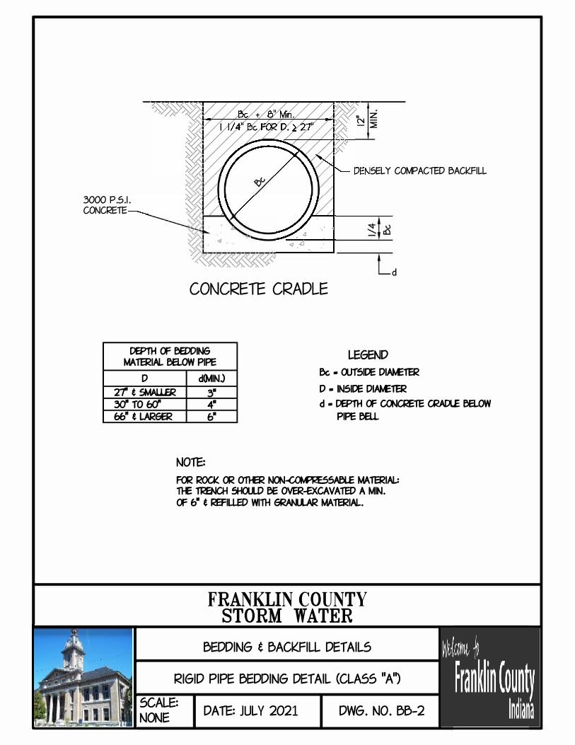
3000 P.S.I.
CONCRETE
-�����,,,'
CONCRETE CRADLE
= z N- ::::E
5EL Y COMPACiED BACK.FILL
DEPTH OF BEDDING LEGEND MA'TERIAL BELOW PIPE
D
zr t SMAL1.ER YI TO l::d
66" t LARGER
d(MIN.) & • OUTSIDE DIAt.£11:R
D • INSIDE DIAt.£11:R 3•
4•
fl
d • DEPTH OF <nlCl<ElE CRADLE BELOW
PIPEeieu.
NOiE:
FOR ROCI( OR 011-ER NON-CCM'r<ESSM31..E MA'TERIAL: 11-E Tl<ENCH 5HCUD BE OVER-fXCAVATED A MIN.
OF 6• t l<EFILJ.ED WITH GRm.LAR MA'TERIAL.
FRANKLIN COUNTYSTORM WATER
BEDDING t BACKFILL DEf AILS
RIGID PIPE BEDDING DEf AIL (CLASS "A'�
SCALE:
NONE DA fE: JULY 2021 DWG. NO. BB-2

cot.PACTED GRANLLAR BACKFILL
FINE GRMIJLAR MATERIAL
0.6&
.... . ......... . ................. , , .. , , .. , , ...................... , , ......................................................................................................
SHAPED SUBGRADE WITH
GRANULAR FOUNDATION
GRANULAR FOUNDATION
DEPTHCFeEDDNG LEGe.l) MA1ERIAL ea.ow PFE
ix • rursa:,e � D•N51?E�
D
Zftst.W.LER
'!dTOfn
�•tl.AR6ER
<Ml.)
3•
4•
6.
NOTE:
d • DEPTH CF eEDDNG MA1ERIAL ea.ow
PFE eELL
FCR l<OCI( CR 01l£R � MA'fERW.: Tl£ TlcENCH 5HCU.D eE <Nf!R.-EICAVATfD A Mt!. CF 6• t la:FUED Wl1H 6RAN.lAR MA1ERIAL.
FRANKLIN COUNTYSTORM WATER
BEDDING t BACKFILL DEf AILS
RIGID PIPE BEDDING DEf AIL (CLASS "B'�
SCALE:
NONE DA fE: JULY 2021 DWG. NO. 00-3
SPRING LINE
a= PIPE

12"Mn.
Den!iely Compacted Badfill
GRANULAR FOUNDATION
DEPTH a= eEODN6 MATERIAL ea.ow PFE
LEGal)
& • OOTSIJE DW.£TER
D • N5IJE DW.£TER
NOTE:
d • DEPTH a= eEODN6 MATERIAL ea.owPFE eeu.
Far Rock « other � Material: The Trench !hcJUld be CMr-acavated a ni,. " ,,. t retied with Eiraucr Material.
FRANKLIN COUNTYSTORM WATER
BEDDING t BACKFILL DETAILS
RIGID PIPE BEDDING DETAIL (CLASS "C'�
SCALE:
NONE DA TE: JULY 2021 DWG. NO. 00-4

R/W
I
_____________ R/W Un��----------
M.H. M.H.
t Improved Street
Curb Une
M.H. M.H.
------------R/W
lin e�----------
,,___,_ __ Backflli-------r -e• Borrow or f8
Area -e·
R/W
I
SCALE:
NONE
NOTE: PLACE A FABRIC LAYER ON TOP OF THE
11
B11
BORROW OR #B STONE PRIOR TO PLACEMENT OF THE COMPACTED #53 OR #73 STONE BASE
(FOR PIPE LINES WITHIN RIGHT OF WAY FOR IMPROVED STREETS)
FRANKLIN COUNTYSTORM WATER
BEDDING t BACKFILL DEf AILS
BACK.FILL REQUIREM=NfS (WITHIN R/W)
DA fE: JULY 2021 DWG. NO. BB-5

_____________ R/W U�- ________ _
Pipe Une
R/W
NOTE:
PLACE A FABRIC LAYER ON TOP OF THE 11
B11
BORROW OR #B STONE PRIOR TO PLACEMENT
OF THE COMPACTED #53 OR #73 STONE BASE
( FOR PIPE LINES CROSSING RIGHT OF WAY FOR IMPROVED STREETS)
FRANKLIN COUNTYSTORM WATER
BEDDING t BACKFILL DEf AILS
BACKFILL REQUIREMENfS (CROSSING R/W)
SCALE:
NONE DA fE: JULY 2021 DWG. NO. 00-6
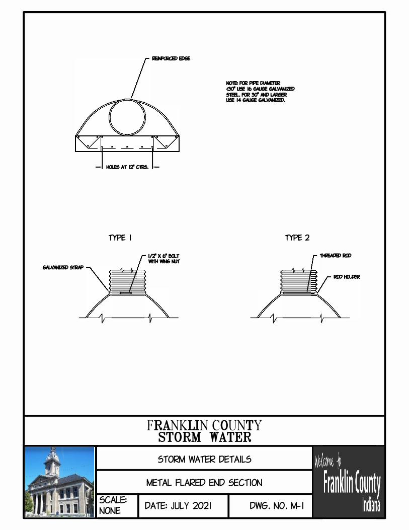
&ILVIWIB) 51RIP
RBF<RB>B>eE
NOIEi FCR PFE WM:1IR <YI U!E 16 6MJ6E &ILVIWIB) 51&1.. FCR "1 NI:> l.laiER U!E 14 6MJ6E &ILVIWIB).
Ha.E5 AT 11' C1R5.
fYPE I
SCALE:
NONE
1/'J'X&•ea.r Yl11HWIN&N.lf
FRANKLIN COUNTYSTORM WATER
STORM WATER DETAILS
MET AL FLARED END SECTION
fYPE 2
DATE:JULY 2021 DWG. NO. M-1
n&ADB)Ra)

SCALE:
NONE
I II I
lo�.I
A TTER 3" PER FOOf
BATTER 3" PER Fi.
••'TRASH GRA1'E 114 l<E:E>AR w/ WELDED JOINfS
Pl<EMAN.FAClUl<ED CONCRE1'E R..ARED EtD SECTION CONCRE1'E SHALL BE 3.000 PS.I. (MINIM.M) EXACf Dlt.ENSIONS PER 11-E MAN.FAClUl<E
NOTE: PLACE FASTBERS INrO CONC. END SECTION AW eia..r 'TRASH GRA1'E MJSf BE AE>I.E ro BE l<EMOVED FOR CLEANING AW MAINTENANCE.
•SEE �ILES FOR PIPE SIZE
FRANKLIN COUNTYSTORM WATER
STORM WATER DETAILS
CONCRETE FLARED END SECTION
DATE:JULY 2021 DWG. NO. M-2

3' 3' 3'
NOTES: I. PLACE PERMANENT SEEDING l�IATEL Y AFTER FINISI-ED GRADING 15 CCM'LETE.
1l£ SEED MIXlll<E FOi< THIS PIW.ECT 5HAU.. BE SEED A5 F<llOW5:
5EEP DESCRIPTION PERCENT <l:>X VEIGttO KENTUCKY 6UJE GRA55 40 TO 50 CREEPING l<ED FE5ClE 40 TO 45 PB<ENNIAL RYE 5 TO 10
IT 5HAU.. BE APPLIED AT A RATE OF 215 PCUND5 PER ACRE
(5 PCUND5 PER l,000 5CllARE FEET.) SEED MIXlll<E 5HAU.. NOT CONTAIN MORE THAN S'i I� MATTER ND CONTAIN NO 00.ECTIONAL \'EEDS.
FRANKLIN COUNTYSTORM WATER
STORM WATER DETAILS
GRASS SWALE
SCALE: DATE:JULY 2021 DWG. NO. M-3
NONE

INDOT DRAWINGS ADOPTED BY REFERENCE
INDOT Catch Basins INDOT Catch Basin Type A E 720-CBST-01 INDOT Catch Basin Type D E 720-CBST-02 INDOT Catch Basin Type E E 720-CBST-03 INDOT Catch Basin Type J E 720-CBST-04 INDOT Catch Basin Type K E 720-CBST-05 INDOT Catch Basin Pipe E 720-CBST-06 INDOT Catch Basin Type S E 720-CBST-07 INDOT Catch Basin Type W E 720-CBST-08 INDOT Catch Basin Hood E 720-CBST-09
INDOT Inlet & Catch Basin Castings INDOT Pipe Catch Basin Casting E 720-CBCA-01 INDOT Compatibility of Drainage Structures and Castings E 720-CDSC-01 INDOT Earth Ditch Casting Type 7 E 720-EDCA-01 INDOT Casting Type 5 Frame E 720-ICCA-01 INDOT Casting Type 5 Alternate Bolted Frame E 720-ICCA-02 INDOT Casting Type 5 (Alternate) Frame and Grate E 720-ICCA-03 INDOT Casting Type 8 Frame E 720-ICCA-04 INDOT Casting Type 8 Grate E 720-ICCA-05 INDOT Casting Type 8 Curb Box E 720-ICCA-06 INDOT Casting Type 10 Frame E 720-ICCA-08 INDOT Casting Type 10 Grate E 720-ICCA-09 INDOT Casting Type 10 Curb Box E 720-ICCA-09A INDOT Steel Grating Type 12 Frame and Grate E 720-ICCA-10 INDOT Casting Type 12 (Alternate) Frame and Grate E 720-ICCA-11 INDOT Steel Grating Type 12A Frame and Grate E 720-ICCA-12 INDOT Casting Type 13 Frame and Grate E 720-ICCA-13 INDOT Casting Type 14 Frame and Grate E 720-ICCA-15 INDOT Casting Type 15 Frame and Grate E 720-ICCA-16 INDOT Casting Type 15 Grate E 720-ICCA-17 INDOT Casting Type 15 Curb Box E 720-ICCA-18 INDOT Casting Type 15 (Alternate) Frame, Grate and Curb Box E 720-ICCA-19 INDOT Inlet Casting Type 6 E 720-INCA-01 INDOT Curb Inlet Casting Type 3 E 720-INCA-02
INDOT Pipe End Sections INDOT Metal Pipe End Section E 715-MPES-01 INDOT Metal Pipe Arch End Section E 715-MPES-02 INDOT Metal Pipe End Section Connections E 715-MPES-03 INDOT Precast Concrete End Section E 715-PCES-01

INDOT Inlet Structures INDOT Inlet Type A E 720-INST-01 INDOT Inlets Type B and C E 720-INST-02 INDOT Inlet Type D E 720-INST-03 INDOT Inlets Type E and F E 720-INST-04 INDOT Inlet Type G E 720-INST-05 INDOT Inlet Type J E 720-INST-06 INDOT Inlets Type M and R E 720-INST-07 INDOT Inlet Type N E 720-INST-08 INDOT Inlet Type P E 720-INST-09 INDOT Inlets Type S and T E 720-INST-10 INDOT Manhole Castings INDOT Flat Top Grate Casting Type 2 E 720-MHCA-01 INDOT Manhole Casting Type 4 Ring and Cover E 720-MHCA-02 INDOT Manhole Casting Type 4 Alternate Cover E 720-MHCA-03 INDOT Manhole Structures INDOT Manholes Type A and B E 720-MHST-01 INDOT Manhole Type C E 720-MHST-02 INDOT Manholes Drop Manhole Type C E 720-MHST-03 INDOT Manholes Type D, E, F and G E 720-MHST-04 INDOT Manholes Type H, J, K, L, M and N E 720-MHST-05 INDOT Precast Concrete Manhole Sections E 720-MHST-06 INDOT Precast Concrete Manhole Bottom Section E 720-MHST-07 INDOT Manhole Bars and Concentric Cone E 720-MHST-08 INDOT Manhole Step E 720-MHST-09 INDOT Table of Reinforcing Steel for Manholes E 720-MHST-10 INDOT Slotted Drains INDOT Slotted Drain Pipe E 715-SLDR-01 INDOT Slotted Drain Pipe E 715-SLDR-02 INDOT Slotted Vane Drain Pipe E 715-SLDR-03 INDOT Slotted Drain Pipe Cleanout Port E 720-SDCP-01 INDOT Casting Type I Frame and Grate E 720-SDCP-02 INDOT Casting Type II Frame and Grate E 720-SDCP-03