framework - openseesopensees.berkeley.edu/opensees/workshops/openseesdays2012/a9...and plate model...
TRANSCRIPT

20/08/2012
1
UNIVERSITY OF PADUA ITALY Dept. Civil Environmental Arch. Eng.
UNIVERSITY OF CALIFORNIA BERKELEYDept. Civil and Environmental Eng.
Leopoldo Tesser and Filip C. Filippou
Cyclic Inelastic Analysisof RC Shear Walls and Plates
OpenSees Days 2012, August 15‐16
Framework
Introduction Models Implementation Analyses Conclusions 1/36
Performance based design methodology
Seimic Hazard Analysis
Response Analysis
Damage Analysis
Loss Analysis

20/08/2012
2
Framework
Introduction Models Implementation Analyses Conclusions 1/36
Performance based design methodology
Seimic Hazard Analysis
Response Analysis
Damage Analysis
Loss Analysis
Background
Introduction Models Implementation Analyses Conclusions 2/36

20/08/2012
3
Experimental Investigations
Introduction Models Implementation Analyses Conclusions 3/36
Maier and Thϋrlimann 1985
Mansour and Hsu 2005
Stevens et al. 1991
JNES 2006
Recent Tests by NEES
Introduction Models Implementation Analyses Conclusions 4/36
Univ. of Michigan
Univ. of Minnesota
Univ. of Illinois
Univ. of CA Berkeley
20/08/2012
4
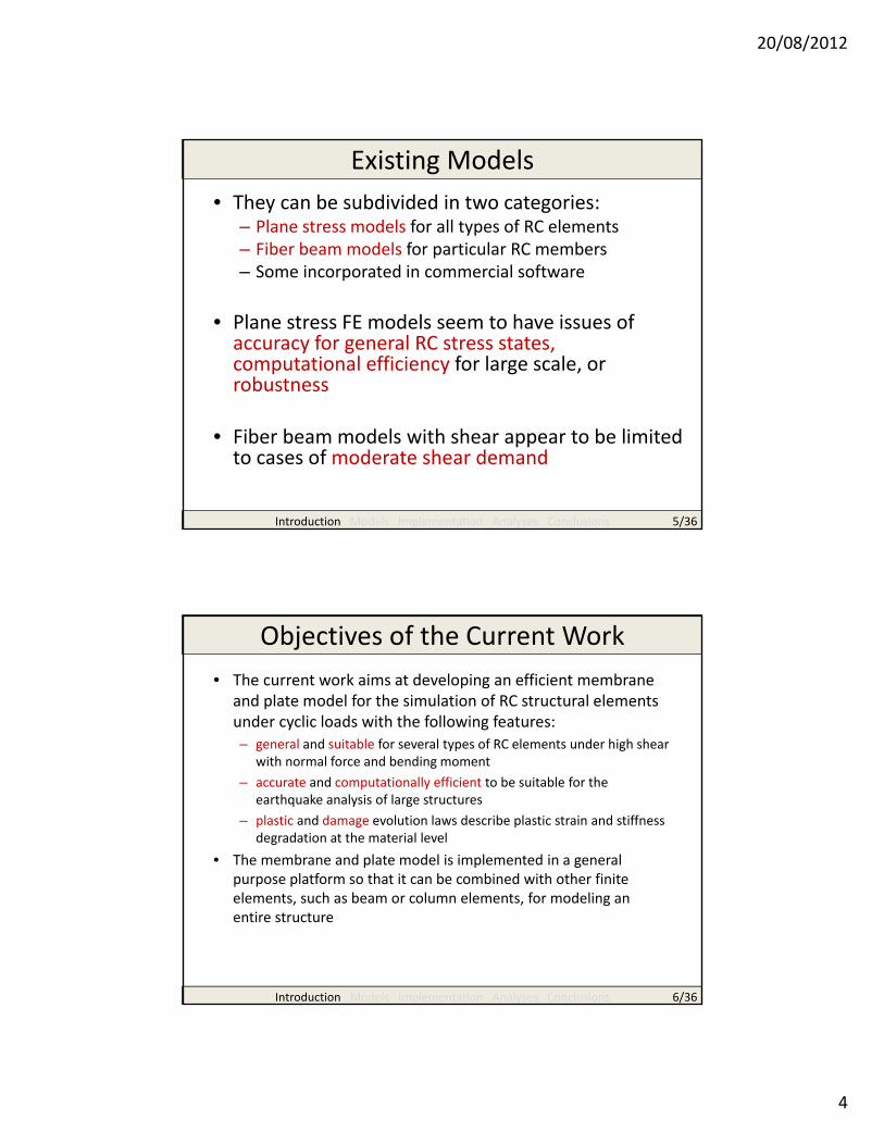
Existing Models• They can be subdivided in two categories:
– Plane stress models for all types of RC elements– Fiber beam models for particular RC members– Some incorporated in commercial software
• Plane stress FE models seem to have issues of accuracy for general RC stress states, computational efficiency for large scale, or robustness
• Fiber beam models with shear appear to be limited to cases of moderate shear demand
Introduction Models Implementation Analyses Conclusions 5/36
Objectives of the Current Work• The current work aims at developing an efficient membrane
and plate model for the simulation of RC structural elements under cyclic loads with the following features:– general and suitable for several types of RC elements under high shear
with normal force and bending moment– accurate and computationally efficient to be suitable for the
earthquake analysis of large structures– plastic and damage evolution laws describe plastic strain and stiffness
degradation at the material level• The membrane and plate model is implemented in a general
purpose platform so that it can be combined with other finite elements, such as beam or column elements, for modeling an entire structure
Introduction Models Implementation Analyses Conclusions 6/36

20/08/2012
5
Experimental Evidences in Uniaxial Conditions
Introduction Models Implementation Analyses Conclusions 7/36
Tension
Compression
Envelope
Introduction Models Implementation Analyses Conclusions 8/36
1

20/08/2012
6
Envelope
Introduction Models Implementation Analyses Conclusions 9/36
1.7
Damage
Residual Strength
ε−=σ Ed1 )(
Cyclic Loading
Introduction Models Implementation Analyses Conclusions 10/36
Residual Strain
)()( pEd1 ε−ε−=σ

20/08/2012
7
Features of the Presented Model• The features of the presented concrete constitutive law are:
– it is a general three‐dimensional law that can be used with all types of finite elements
– both tensile and compressive damage modes are taken into account by means of two scalar damage parameters
– a simplified plasticity evolution law represents the residual strains for all stress states
– it uses a straight forward algorithm for material state determination • The material parameters are calibrated once from experimental
data and used consistently in applications (no parameter “tuning”)• The 3d concrete law is constrained to a plane stress state for the RC
membrane element• The out‐of‐plane stress of the 3D concrete law is condensed out for
use with the RC plate element
Introduction Models Implementation Analyses Conclusions 10/36
Plastic‐Damage Concrete Model
Compression
Introduction Models Implementation Analyses Conclusions 11/36
Sinha et al. 1964Tension
Gopalaratnam and Shah 1985
Separate scalar damage parameters for tension and compression; these arrecoupled under multi‐axial stress states

20/08/2012
8
Crack Width
Introduction Models Implementation Analyses Conclusions 12/36
0 600 1200 1800 2400 3000
Crack width [μin]
0 200 600 1000 1400 1800
Crack width [μin]
• The correlation between average concrete tensile strains, tensile damage parameter and crack width can be derived from experimental measurements
• The correlation holds only for micro‐cracks; this may be suitable for structural durability studies
• For the estimation of large crack widths under seismic excitations the reinforcing steel strains should be used
Multi‐Axial Conditions
Introduction Models Implementation Analyses Conclusions 13/36
0.00.10.20.30.40.50.60.70.80.91.01.11.2
0.0 0.2 0.4 0.6 0.8 1.0 1.2 1.4
Non
dim
ensio
nal stress σ/f
c‐
Non dimensional strain ε/ε c0
Numerical
Experimental
‐1/0.103
‐1/0.052
‐1/0
‐1/0.204
The concrete constitutive law is developed in three‐dimensions and can be used with all types of finite elementsFor the analysis of RC shear walls the most significant biaxial stress state is tension‐compression
Kupfer et al. 1969
ratio ofminimum to maximum
principal stress

20/08/2012
9
RC Membrane Model
Introduction Models Implementation Analyses Conclusions 14/36
Concrete Uniaxial Steel layer
The 3d concrete law is constrained to a plane stress state
RC Membrane Model
Introduction Models Implementation Analyses Conclusions 15/36
Reinforced Concrete Filippou et al. (1983)
Uniaxial steel constitutive relations
The 3d concrete law is constrained to a plane stress state

20/08/2012
10
RC Plate Model
Introduction Models Implementation Analyses Conclusions 16/36
numerical integration over the thickness:
e.g. 7 mid‐points
Insertion of reinforcing layer at actual locations
e.g. 2 reinforcement nets
The out‐of‐plane stress of the 3d concrete law is condensed
Correlation with experiments
Introduction Models Implementation Analyses Conclusions 17/36
The material parameters are calibrated once from experimental data on the concrete material and used consistently in the correlation studies (no parameter “tuning”)

20/08/2012
11
RC Panels
Introduction Models Implementation Analyses Conclusions 18/36
α = 45°
Test CA2: α = 45°
Mansour and Hsu (2005)
-0.04 -0.03 -0.02 -0.01 0 0.01 0.02 0.03 0.04-6
-4
-2
0
2
4
6
Shear Strain [-]
Shea
r Stre
ss [M
Pa]
ExperimentalNumerical
RC Panels
Introduction Models Implementation Analyses Conclusions 19/36
vertical vs. horizontal strain and vertical normal stress vs. strain
0 0.01 0.02 0.03-0.005
0
0.005
0.01
0.015
0.02
0.025
0.03
0.035
Horizontal Strain [-]
Verti
cal S
train
[-]
ExperimentalNumerical
-0.005 0 0.005 0.01 0.015 0.02 0.025 0.03 0.035-4
-3
-2
-1
0
1
2
3
4
Vertical Strain [-]
Verti
cal N
orm
al S
tress
[MPa
]
ExperimentalNumerical

20/08/2012
12
RC Panels
Introduction Models Implementation Analyses Conclusions 20/36
Test CE3: α = 90°
Mansour and Hsu (2005)
α = 90°
RC Panels
Introduction Models Implementation Analyses Conclusions 21/36
vertical vs. horizontal strain and vertical normal stress vs. strain

20/08/2012
13
RC Beams w/o Shear Reinforcement
Introduction Models Implementation Analyses Conclusions 22/36
Leonhardt andWalter 1962
Shear Failure
Introduction Models Implementation Analyses Conclusions 23/36
d‐d+

20/08/2012
14
Flexural Failure
Introduction Models Implementation Analyses Conclusions 24/36
T10
d+
d‐
RC Planar Shear WallsRC Panel with boundary elements(Maier and Thϋrlimann 1985)
Introduction Models Implementation Analyses Conclusions 25/36
d‐
Height: 1200 mm ≈ 47 inAspect ratio: 1Thickness: 100 mm ≈ 4 inVertical reinforcement ratio: 1.16%Horizontal reinforcement ratio: 1.03%Axial load: 416 kN ≈ 94 kips

20/08/2012
15
RC PlatesRC Plates under combinedin‐plane and lateral loads(Ghoneim and MacGregor 1994)
Introduction Models Implementation Analyses Conclusions 26/36
d+
Compressed layer
d‐
Tensed layer
Size: 72 in ≈ 1829 mmThickness: 2.65 in ≈ 67.4 mmIsotropic reinforcement ratio: 0.77% in two gridsIn‐plane biaxial compression: 1400 psi ≈ 9.8 MPaTransverse load carrying capacity: 1440 psf ≈ 69 kPa
RC U‐shaped Shear Wall (1)U‐shaped shear wall(Pégon et al., JRC Ispra, 2000)
Introduction Models Implementation Analyses Conclusions 27/36
Height: 3.6 m ≈ 11 ft 10 inAxial load: 2MN ≈ 450 kips
Dimension in mm

20/08/2012
16
RC U‐shaped Shear Wall (2)
Introduction Models Implementation Analyses Conclusions 28/36
d+
4.45 kN ≈ 1 kips
RC Box Shear Wall (1)
Introduction Models Implementation Analyses Conclusions 29/36
Box‐shaped shear wall (Japan Nuclear Energy Safety Organization 2006)
Height: 1.0 m ≈ 3 ft 3 inAxial load: 670 kN ≈ 150 kips
Dimension in mm

20/08/2012
17
RC Box Shear Wall (2)
Introduction Models Implementation Analyses Conclusions 30/36
d+
4.45 kN ≈ 1 kips
RC Box Shear Wall (2)
Introduction Models Implementation Analyses Conclusions 30/36
d+
d‐

20/08/2012
18
Conclusions (1)• Excellent agreement with correlation studies was observed for
different specimens– concrete cylinders and prisms under cyclic loads (uniaxial stress states)– concrete prisms under combined tension and compression– RC panels under cyclic shear loads (uniform stress state)– beams without shear reinforcement (complex stress states)– planar, U‐ and box‐shaped RC shear walls under axial force and cyclic
lateral loads (complex stress states)
• The tensile and compressive damage parameters of the concrete constitutive law permit the interpretation of observed experimental behavior in regard to– accumulated structural damage– failure mechanisms– tensile cracks location and orientation– micro‐cracks width– concrete compression strut location and orientation
Introduction Models Implementation Analyses Conclusions 31/36
Conclusions (2)• Neglecting the dowel action and bond‐slip of reinforcing bars does
not seem to affect the agreement of the model with the experimental data regarding strength. However,– some discrepancy in unloading and reloading is evident– the dowel action of the reinforcement is statistically significant in
affecting the unloading stiffness the more the orientation of the reinforcing bars deviates from the principal stress directions
• The robustness and consistency of the proposed RC membrane and plate model over a range of structural elements under different stress states holds significant promise for its use as reliable tool for the simulation of structural systems under earthquake excitations
Introduction Models Implementation Analyses Conclusions 32/36

20/08/2012
19
Current Work (1)
Introduction Models Implementation Analyses Conclusions 33/36
T10
Influence of bond‐slip and Bond degradation
Current Work (2)
Introduction Models Implementation Analyses Conclusions 34/36
Shear Deficient Columns
d‐