fracture toughness properties of epoxy...
TRANSCRIPT

FRACTURE TOUGHNESS PROPERTIES OF EPOXY-BASED ADHESIVES
REINFORCED WITH NANO- AND MICROFILLER ADDITIONS FOR IN
SITU TIMBER BONDING.
Zakiah Ahmad, Martin Ansell
Materials Research Centre, Department of Mechanical Engineering,
University of Bath, UK
David Smedley, David Simpson
Rotafix Limited, Abercraf, Swansea, UK
Summary Timber structures are currently restored and/or repaired using a combination of epoxy adhesives and secondary adherends, e.g. fibre reinforced plastics (FRPs) or metallics. This paper highlights the improvements to mechanical properties of epoxy adhesives when reinforced with nano- and micro-filler additions. Three ambient temperature cured two-part epoxy adhesives were compared. Epoxy 1 is a standard diglycidylether of bisphenol A (DGEBA) thixotropic formulation containing silica fume cured with an aliphatic polyetheramine. Epoxy 2 is based on Epoxy 1 modified with carboxyl-terminated butadiene acrylonitrile (CTBN). Epoxy 3 is a commercially used adhesive formulation containing quartz, mica and bentonite and cured with an aliphatic diamine (TMD). The effect of the fillers on the fractured toughness behaviour of the adhesives was investigated using firstly the Charpy impact test (a high strain-rate test) on unnotched and notched specimens to evaluate notch sensitivity, and secondly the three point single-edge notched beam (SENB) test (a low strain-rate test). The fracture surfaces were investigated using scanning electron microscopy (SEM). Under high strain rates toughness was in the order of Epoxy 1, 2 and 3. Epoxy 1 and 2 were found to be ductile in the unnotched state and brittle when notched. Epoxy 3 was brittle under both unnotched and notched states. Under low strain rate conditions the addition of CTBN significantly improved the toughness of Epoxy 2 compared with Epoxy 1. Epoxy 3 was considerably more brittle than Epoxy 1 and Epoxy 2. The low strain-rate SENB test rate allowed the dilation and cavitation of rubbery particles to occur in Epoxy 2 which promoted more extensive shear yielding in the matrix and therefore increased energy absorption. Examination of the topography of the fractured surface revealed marked changes in crack propagation due to the addition of nano- or micro-fillers accounting for the variation in toughness properties. The toughness of thixotropic adhesives, specified for bonding in connections in timber structures, will therefore be enhanced by the inclusion in the epoxy matrix of phase separated liquid rubber. 1. Introduction In timber repairs and reinforcement, steel plates, rods or bolts are bonded into timber with high strength adhesives to produce concealed timber connections. Studies have shown these bonded-in connections produce strong and stiff connections [1, 2]. Adhesives used for in-situ bonding of pultruded rods into timber must be room temperature curing and thixotropic for easy application and applied without pressure. Rotafix Ltd, based in Wales, United Kingdom, manufactures adhesives for timber and concrete repairs. CB10TSS is thixotropic room temperature cured epoxy-based adhesive used for bonded-in connection. However this adhesive has a glass transition temperature of ~30°C and considered low for exterior application. In order to raise the glass transition temperature, the CB10TSS formulation has been modified by reinforcing CB10TSS with nano-sized particles (liquid rubber) and micro-particles (ceramics) and denoted as Albipox and Timberset. Nano- and micro filler particles added to adhesives are generally employed to improve toughness but studies have shown that these filler particles can also increase the glass transition

temperature and mechanical properties of the adhesives with additions of the correct proportion of the fillers [3, 4], hence improving strength of adhesive joints. In general, in many adhesive systems in which modulus, strength and glass transition temperature are increased with inclusion of fillers, a decrease in toughness is observed. It is widely believed that the brittleness of epoxy resins is associated with their highly cross-linked structures [5], which absorb very small amounts of energy during the fracture process [6]. An improved toughness has been seen in some epoxy/clay systems, and attributed in part, to the intercalated regions shearing during crack growth and increased crack surface area, leading to dissipation of energy [7]. McGarry and his co-workers [8, 9] studied the addition of liquid rubbers into thermoset resins and their study showed a significant improvement in the fracture toughness and suggested that the toughening mechanisms involved generation of crazes and shear banding in the vicinity of rubber particles. This was based on the observation of a stress whitened zone. Yee and Pearson [10] disagree with the theory and in turn suggested that the stress whitening zone was due to the micro-cavitation (voiding) of rubber particles. Bucknall [11] has also postulated that the crazing of a matrix containing rubber particle phase enhances the toughness. Kinloch [12] concludes that the mechanism of toughening resulting from rubbery particles or phases are: (a) localized shear yielding or shear banding in the epoxy polymer which occurs between the rubbery particles, (b) plastic hole or void growth in the epoxy polymer which is initiated by cavitation or debonding of the rubber particles and (c) rubber particles bridging the crack surfaces. In the previous study by the author on the mechanical and thermal properties of CB10TSS, Albipox and Timberset [13], Albipox was shown to have higher tensile and flexural strength and glass transition temprature than CB10TSS while Timberset has the highest modulus of elasticity and glass transition temperature. As mentioned above the addition of fillers can also reduce the toughness properties of the adhesives, therefore the effect of nano- and micro-particles on the toughness properties of CB10TSS is investigated and reported in this paper. Two methods were employed to measure toughness. The first is Charpy impact test which is high strain rate test and unnotched and notched specimens were used since it is a convenient method for evaluating notched sensitivity of the adhesives. The second is the 3 point single-edge notched beam test (SENB) which is a low strain rate test. 2. Experimental procedures 2.1 Materials Three types of adhesive obtained from Rotafix Ltd were used in this study. The first type is the standard adhesive (CB10TSS) which is a mixture of diglycidylether of bisphenol-A (DGEBA) with reactive diluent glycidlyether (monofunctional), silica fume particles and hardener, a mixture of polyetheramines. This CB10TSS is considered the standard adhesive. The other two adhesives were formulated from standard adhesive but with the addition of either liquid rubber (carboxyl-terminated butadiene and acrylonitrile (CTBN)) or micro-particles (a mixture of bentonite, quartz and mica) and these adhesives were designated as Albipox and Timberset. 2.2 Preparation of specimens and experimental measurements 2.2.1 Charpy impact Test A 4 mm thick adhesives sheet was prepared and the Charpy impact specimens were cut from the sheet in accordance with BS ISO 179:1996. Figure 1.1a and b show the dimensions of the specimens both for unnotched and notched specimens respectively.
(a) (b) where bN is the remaining width at the notch base of the test. Fig. 1: Geometry and dimensions of the Charpy impact specimen, (a) unnotched specimen and (b) notched specimen.
b=10
80 mm
h=4
bN= 8 2 mm
h=4
80 mm
45°
The Charpy impact test was conducted at room temperature, in equipment with a maximum pendulum capacity of 4 J and the tests were conducted in accordance with BS ISO 179:1996. 2.2.2 Single-edge notched bend (SENB) test
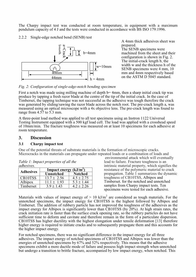
Fig. 2: Configuration of single-edge-notch bending specimen
A 4mm thick adhesives sheet was prepared. The SENB specimens were machined from the sheet and their configuration is shown in Fig. 2. The initial-crack length b, the width w and the thickness h of the SENB specimens were 4 mm, 10 mm and 4mm respectively based on the ASTM D 5045 standard.
First a notch was made using milling machine of depth b= 4mm, then a sharp initial crack tip was produce by tapping a fresh razor blade at the centre of the tip of the initial crack. In the case of Timberset, the tapping technique was not successful as the adhesive was tough therefore the crack was generated by sliding/sawing the razor blade across the notch root. The pre-crack length a, was measured using an optical microscope with a 4x objective lens. The pre-crack length was found to range from 4.57 to 5.3 mm. A three-point load method was applied to all test specimens using an Instron 1122 Universal Testing Instrument equipped with a 500 kgf load cell. The load was applied with a crosshead speed of 10mm/min. The fracture toughness was measured on at least 10 specimens for each adhesive at room temperature. 3. Discussion 3.1 Charpy impact test One of the potential threats of substrate materials is the formation of microscopic cracks. Microcracks in the materials can propagate under repeated loads or a combination of loads and Table 1: Impact properties of all the adhesives.
Impact energy (kJ/m2)
Adhesives Unnotched Notched
CB10TSS 13.7 ± 2.56 4.5 ± 2.75 Albipox 11.1 ± 1.93 5.3 ± 1.44 Timberset 3.9 ± 1.43 4.2 ± 2.26
environmental attack which will eventually lead to failure. Fracture toughness is an intrinsic material property, which signifies the resistance of the polymeric material to crack propagation. Table 1 summarizes the dynamic toughness of CB10TSS, Albipox and Timberset. for the notched and unnotched samples from Charpy impact tests. Ten specimens were tested for each adhesive.
Materials with values of impact energy of > 10 kJ/m2 are considered as tough materials. For the
unnotched specimens, the impact energy for CB10TSS is the highest followed by Albipox and Timberset. The addition of rubbery particle has not improved the toughness of the adhesives as the impact energy for Albipox is significantly lower than CB10TSS (by 20%). At high strain rates, the crack initiation rate is faster than the surface crack opening rate, so the rubbery particles do not have sufficient time to deform and cavitate and therefore remain in the form of a particulate dispersion. CB10TSS has higher ductility with the highest elongation under tensile deformation [13] therefore higher energy is required to initiate cracks and to subsequently propagate them and this accounts for the higher impact energy. For notched specimens, there was no significant difference in the impact energy for all three adhesives. The impact energy of notched specimens of CB10TSS and Albipox was lower than the energies of unnotched specimens by 67% and 52% respectively. This means that the adhesive specimens exhibit a more ductile mode of failure and possess high impact strength when unnotched but undergo a transition to brittle fracture, accompanied by low impact energy, when notched. This
44mm
40mm
w=10mm
h = 4mm
b=4mm
a=Crack
length

behaviour arises from the notch tip where there is locally a high triaxial stress concentration and an increased rate of strain at the notched tip [14]. Hence CB10TSS and Albipox are tough material when unnotched. When subjected to impact, energy is absorbed in the process of plastic deformation of the adhesive matrix, debonding at the adhesive to filler interface and fracture of the filled adhesive [14]. In the case of Timberset, containing micro-sized ceramic filler particles, there is no significant difference in the impact energy for notched and unnotched specimens and Timberset has the lowest impact energy compared to CB10TSS and Albipox. This may be due to weak particle/matrix adhesion and also the bigger size of the filler particles. According to Hojo et al [15], for a given volume fraction of filler, the fracture strength of silica-filled epoxy adhesives was decreased as the average size of the particles increased. By applying the Vincent notch sensitivity criterion [16], the CB10TSS and Albipox can be characterized as materials that are ductile in an unnotched state and brittle when a notch is introduced (notch brittle). Timberset is a material which is brittle both in the unnotched and notched states. In conclusion, under high strain rate impact in the unnotched state, CB10TSS is the toughest adhesive followed by Albipox and Timberset. Notching the adhesives has the effect of reducing the toughness of the three adhesives to a similar value. 3.2 Single-edge notched bend (SENB) test Cantwell [17] states that the failure mode of epoxy-based adhesives is generally characterized by flaw growth and progressive crack propagation. The energy criterion for fracture based on the work of Griffith [18] and Irwin [19], is that fracture occurs when there is sufficient energy for crack propagation at the instant ofimpact. The strain energy release rate (G1C) provides a measure of the Table 2: SENB fracture toughness properties of the adhesives.
Adhesives KIC (MPam
½)
GIC (kJm
-2)
CB10TSS 2.2 ± 0.31 1.9 ± 0.58 Albipox 3.7 ± 0.99 3.8 ± 1.20 Timberset 2.5 ± 0.41 0.7 ± 0.20
critical energy required to extend a mode I crack over a unit area and is often abbreviated to “fracture energy”. The local concentration of stresses at the crack tip in relation to the applied stress is measured by the critical-stress-intensity factor (KIC) and is sometimes called the “fracture strength”. Table 2 presents critical strain energy release rate and critical-stress-intensity factor values for the epoxy-based adhesives containing nano- and micro-filler additions.
Values of critical strain energy release rate, GIC for CB10TSS and Albipox are 1.9 and 3.8 kJm-2
respectively and values for the critical stress intensity factor, KIC are 2.2 and 3.7 MPam½
respectively. This study has demonstrated that the addition of nanorubber particles successfully toughens the CB10TSS adhesive system by raising the value of GIC and KIC. Before the addition of nanorubber, the average GIC value for CB10TSS was 1.9kJm
-2 which is higher than reported values
for epoxy adhesives (≈ 0.1 – 0.2 kJm-2) [20] due to partial crosslinking in the room temperature cure
adhesive, providing some ductility. By reinforcing CB10TSS with nano-rubber, the fracture energy increases to 3.8 kJm
-2 close to reported values for CTBN-filled epoxy adhesives where the GIC value
is in the range of 4 – 5.8 kJm-2 [21]. The differences are due to the toughening induced by the
rubbery particles. According to Kinloch et al [22], the dispersed rubbery particles greatly increase the toughness of the material via interactions of the stress field ahead of the crack tip and the rubbery particles which leads to greatly enhanced plastic deformation of the epoxy matrix. There was higher variability in both GIC and KIC for Albipox (Table 2) compared to the other adhesives which may be due to variations in the mode of crack propagation and the distribution of rubbery particles around the propagating cracks. The presence of rigid particles (silica, mica and bentonite) provides no significant improvement in the KIC value of Timberset when compared with CB10TSS even though the mean KIC for Timberset is higher than the mean KIC for CB10TSS. The GIC value for Timberset is 60% lower than the GIC value for CB10TSS due to the more brittle

nature of the rigid filler particles. However the KIC value of Timberset is increased in proportion to CB10TSS because of the high modulus of elasticity of the particles. 3.3. Fracture surface morphology
Fig. 3: Schematic representation of the fracture surface of the nano- and micro-filled adhesives.
The fracture surface morphology of the adhesives was examined following Charpy impact tests on unnotched and notched samples and from the SENB test specimens. After investigating all the fracture surfaces, three kinds of damage zones were observed which separated by quite distinct boundaries. The boundary joining the different regions can be abrupt or show incipient deformation marks. In general, the first zone is near the crack initiation point followed by a quite smooth zone which is followed by a rough zone and these zones are shown schematically in Fig.3.
The surface morphologies of unnotched specimens of CB10TSS, Albipox and Timberset are shown in Figures 4 to 6 respectively. Each figure contains several micrographs which are taken starting from the edge where the cracks initiated. Fig. 4 presents the topographical features observed on the fracture surface of an unnotched CB10TSS Charpy specimen. Fig. 4a locates the position of Figures 4b and 4c.
Fig. 4: SEM micrographs of the fracture surface of an unnotched Charpy CB10TSS impact specimen: (a) schematic diagram of the area taken for Figures 4b and 4c, (b) different zones of crack propagation - the arrow shows the direction of crack propagation, transition zone between the crack initiation point A and smooth zone B , x 25, (c) an abrupt jump (marked C) between smooth and rough zones, x 27, and (d) final propagation zone (marked D in (c)), x 900. The crack initiation point can be seen clearly in Fig. 4b. In this case the crack initiated at the top left hand corner of the fracture surface marked by A. The large air bubble is most likely the cause of crack initiation. The crack surface surrounding this initiation region is relatively smooth which is the result of rapid initial crack growth. The relatively smooth region, marked by B in Fig. 4b is separated from region A by a smooth transition zone, shown in Fig. 4d at a higher magnification.
Initiation
point Smooth
zone
Rough zone
(c)
(a)
A
B C
(b)
D
Direction of impact
Crack initiation Direction of crack
Crack jump marked C in Fig. 4c
(d)
(b)
D B

The surface of zone B exhibits striation marks resembling flow marks running in the direction of crack propagation. The presence of striations in contrast to a glassy surface indicates more energy absorption [23]. The soft ridges of the plastic deformation are spread smoothly over three quarters of the fractured area. It has been suggested that the smooth region corresponds to the region of crack acceleration [24]. These striations become less regular and the surface becomes rougher and more textured as shown in Fig. 4c followed by an abrupt jump (marked C) to a much rougher area covering the remainder of the surface to the right of the fractured cross-section with some slip/jump propagation as shown in Fig. 4e at higher magnification. According to Cantwell et al [25] the jump between the smooth and rough region is associated with the crack reaching its terminal velocity. The rough surface indicates that considerable branching of the primary crack has occurred. Therefore the smooth region is said to be a ductile region and the rough area is related to a brittle region [26].
SEM micrographs of the fracture surface of Albipox are shown in Fig. 5 which also show three distinct features of crack propagation as marked by E (initiation), F (smooth propagation zone) and G (rough zone) as presented in Figures 5a and 5b. The crack appears to have initiated at the centre left hand edge of the fracture surface, marked by E in Fig. 5a.
Fig.5: Scanning electron micrographs of the fracture surface of Albipox unnotched specimens; (a) different zones of crack propagation - the arrow shows the direction of crack propagation, transition zone between the crack initiation point E and smooth zone F and direction of crack propagation adjacent to the crack initiation, at x 27, (b) transition zone between smooth (F) and rough(G) zones, x 27 (c) final propagation zone (marked G), x450. The crack propagation marks, which radiate from the point at which the crack initiated in the smooth region (marked F) of the fracture surface of Albipox, appear to be coarser than the smooth region of CB10TSS (Fig. 5b). This implies that the crack propagates at a slower rate in Albipox specimen compared to CB10TSS, most likely due to the nanorubber content of the adhesive. According to Ting [27], more energy is required to accelerate the crack if the surface is rougher. At higher magnification, the smooth fracture region (Fig. 5c) for Albipox shows a tearing zone with sharper edges compared to CB10TSS which relates to higher plastic deformation. The rough zone G for Albipox (Figures 5b and 5c) exhibits more jumps hence high roughness compared to CB10TSS (Figure 4e), which results in more energy absorption. However this observation contradicts the impact energy values is Table 1 which has been explained as high energy required for CB10TSS to initiate the cracks.
Fig.6: Scanning electron micrographs of the fracture surface of Timberset unnotched specimens; arrow head shows direction of crack propagation, smooth zone (marked I) and final propagation zone (marked J), x 27s
(a)
F
E G
(b) (c)
G
(c)
H
I I J
Sharp edges
indicates
plastic
deformation F

The fracture surfaces of Timberset also exhibit three different crack propagation regions as presented in Fig. 6. The cracks appear to initiate by the debonding of particles near the edge of the fracture surface (marked H). Then the cracks propagate further until they reached a step marked J. The fracture surface is brittle in the relatively smooth zone marked I with no evidence of shear yielding in the matrix, so less energy is absorbed. The filler particles are still intact with very little debonding from the matrix. In the final crack propagation zone marked K, the surface is also planar and brittle following the jump at J. In the case of the fracture surface morphologies of notched specimens of CB10TSS, Albipox and Timberset from Charpy impact tests, they show three distinct different crack propagation zones compared to the surface of unnotched specimens as shown in Figures 7, 8 and 9. CB10TSS and Albipox show similar features. The smooth region for CB10TSS (Fig. 7a) is smaller than the smooth region for Albipox (Fig. 8a) and less plastic deformation occurs which indicates less energy absorption.
Fig. 7: SEM microscopy of the fracture surface for CB10TSS (Charpy notched specimen): (a) with initiation zone L, Propagation zone M and rough zone N at x 30, (b) the transition between M and N, x 80.
Fig. 8: SEM microscopy of the fracture surface for Albipox (Charpy notched specimen): (a) initiation P and smooth fracture Q zones at x 30, (b) the transition between smooth Q and rough R regions, x 45.
Fig. 9: SEM microscopy of the fracture surface for Timberset (Charpy notched specimen): (a) initiation S, smooth zone T and rough zone U at x 27, (b) the transition ridge showing the jump between smooth T and rough zone U, x130. 3.3.1 Fracture surface morphology for single-end notched bend test. Figures 10, 11, and 12 show the surface morphologies of SENB specimens of CB10TSS, Albipox and Timberset. Three distinct zones appear on the fracture surfaces of CB10TSS (Fig. 10) and Albipox (Fig. 11) specimens which are more obvious than the features on the fracture surfaces from
(a) (b)
L M N
(a) (b)
Q P Q R
(a)
S T U
(b)
T U
N
Q R
M

Charpy impact test specimens and these features distinguish the effect of high strain rate loading and low strain rateloading
Fig. 10: SEM micrographs of the fracture surface of the SENB specimen for CB10TSS: (a) cut edge V, smooth zone W and rough zone X, x 30, (b) shear deformation W in second zone, x 130 and (c) transition zone between smooth W and rough X zones, x 300.
Fig.11: SEM micrographs of the fracture surface of the SENB specimen for Albipox: (a) the initiation cut Y and smooth zone Z, x 130, (b) shear deformation in Z, x 600 and (c) transition zone between smooth Z and rough AA zones, x 300. With the crack travelling from left to right in Fig. 10a and 11a, the first region is the mirror-like region marked V and Y representing the pre-crack from the razor blade cut and fast fracture initiates from the right hand edge of this zone. The smooth zone W and Z is relatively flat, due to the slow loading rate, with plastic cleavage derived from the tearing of matrix ligaments. The boundary between the zones marked W and X and Z and AA is wavy and unstable. The third zone X and ZZ was rough, corresponding to a zone of crack propagation with a high crack velocity [25]. The rough region exhibits a strong three dimensional appearance, this being associated with extensive branching of the principal crack which can clearly seen in Figures 10c and 11c. As mentioned by Cantwell et al [25], the crack has reached its limiting velocity in the rough region. The smooth zone for Albipox (Fig. 11b) is coarser compared to the smooth zone of CB10TSS (Fig. 10b) which is due to shear yielding of the epoxy matrix which occurs between the rubbery particles. The appearance of little holes can be seen in Fig.11b which cannot be seen in Charpy impact tests. Therefore the slow loading allows the rubbery particles to cavitate and increase the shear banding in the matrix, hence absorbed more energy in order to accelerate the cracks. The area of smooth zone for Albipox is smaller than the area of smooth zone for CB10TSS. There must be a reasonable relationship between the energy available to rupture and the size of this zone which was not determined in this study.
The roughness of CB10TSS and Albipox in the third region (Figures 10c and 11c) also varied and CB10TSS appeared to be smoother than Albipox. The Albipox has more slip and jump features which indicate more energy required for cracks to propagate, correlating with the high fracture energy measured for Albipox. Fig. 12(a) shows the SEM micrographs of failed Timberset which also show smooth and rough zones but because of the large size of the filler particles the zone between the smooth and rough areas is not so obvious. Timberset experiences rapid brittle fracture with the absence of significant plastic deformation which explained its lower fracture energy, GIC, value. Fig. 12(c) shows extensive damage in the form of debonding and micro-cracking in the rough zone DD and at the
(b) (c)
W
V W
W X X
(a)
(a) (b)
Y AA Z
(c)
Z Z
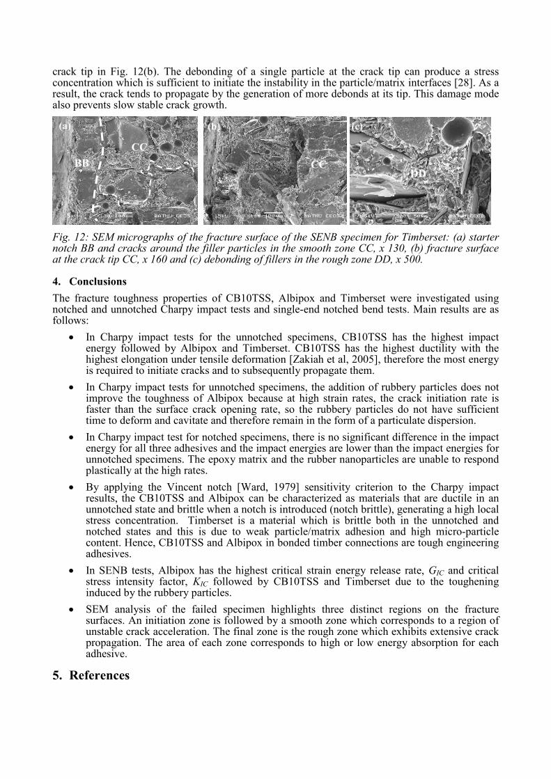
crack tip in Fig. 12(b). The debonding of a single particle at the crack tip can produce a stress concentration which is sufficient to initiate the instability in the particle/matrix interfaces [28]. As a result, the crack tends to propagate by the generation of more debonds at its tip. This damage mode also prevents slow stable crack growth.
Fig. 12: SEM micrographs of the fracture surface of the SENB specimen for Timberset: (a) starter notch BB and cracks around the filler particles in the smooth zone CC, x 130, (b) fracture surface at the crack tip CC, x 160 and (c) debonding of fillers in the rough zone DD, x 500. 4. Conclusions The fracture toughness properties of CB10TSS, Albipox and Timberset were investigated using notched and unnotched Charpy impact tests and single-end notched bend tests. Main results are as follows:
• In Charpy impact tests for the unnotched specimens, CB10TSS has the highest impact energy followed by Albipox and Timberset. CB10TSS has the highest ductility with the highest elongation under tensile deformation [Zakiah et al, 2005], therefore the most energy is required to initiate cracks and to subsequently propagate them.
• In Charpy impact tests for unnotched specimens, the addition of rubbery particles does not
improve the toughness of Albipox because at high strain rates, the crack initiation rate is faster than the surface crack opening rate, so the rubbery particles do not have sufficient time to deform and cavitate and therefore remain in the form of a particulate dispersion.
• In Charpy impact test for notched specimens, there is no significant difference in the impact
energy for all three adhesives and the impact energies are lower than the impact energies for unnotched specimens. The epoxy matrix and the rubber nanoparticles are unable to respond plastically at the high rates.
• By applying the Vincent notch [Ward, 1979] sensitivity criterion to the Charpy impact
results, the CB10TSS and Albipox can be characterized as materials that are ductile in an unnotched state and brittle when a notch is introduced (notch brittle), generating a high local stress concentration. Timberset is a material which is brittle both in the unnotched and notched states and this is due to weak particle/matrix adhesion and high micro-particle content. Hence, CB10TSS and Albipox in bonded timber connections are tough engineering adhesives.
• In SENB tests, Albipox has the highest critical strain energy release rate, GIC and critical
stress intensity factor, KIC followed by CB10TSS and Timberset due to the toughening induced by the rubbery particles.
• SEM analysis of the failed specimen highlights three distinct regions on the fracture
surfaces. An initiation zone is followed by a smooth zone which corresponds to a region of unstable crack acceleration. The final zone is the rough zone which exhibits extensive crack propagation. The area of each zone corresponds to high or low energy absorption for each adhesive.
5. References
(a)
BB
CC
(b) (c)
CC DD

1. Harvey K., and Ansell M. P., “Improved timber connections using bonded-in GFRP rods”, Proceedings of 6
th World Conference on Timber Engineering, Whitsler, British Columbia,
31st July to 3rd August, 2000, P04.
2. Broughton J. G., and Hutchinson A. R., “Efficient timber connection using bonded-in GFRP
rods, composite construction”, Proceeding of International. Conference. on Composites in Construction, Figueiras, J., et al (ed.), Balkema, 2001, p 275-280.
3. Rosso P., and Ye L., “Silica nanocomposites: nanoparticles induced cured kinetics and microstructure”, Macromolecular Rapid Communications, Vol. 28, No.1, 2007, pp 121-126.
4. Bauer F,, Decker U., Ernst H., Findeisen M., Langguth H., Mehnert R., Sauerland V., and Hinterwaldner R., “Functionalized inorganic/organic nanocomposites as new basic raw materials for adhesives and sealants, Part 2”, International Journal of Adhesion & Adhesives, Vol. 26 , 2006, pp. 567–570.
5. Min B. G., and Stachurski Z. H., “Quantitative analysis of the cure reaction of DGEBA/DDS epoxy resins without and with thermoplastic polysulfone modifier using near infra-red spectroscopy”, Polymer, Vol. 34, No. 17, 1993, pp. 3620-3627.
6. Scherzer T., “Characterization of diol modified epoxy resins by near- and mid-infrared spectroscopy”, Journal Applied Polymer Science, Vol. 51, No.3, 1994,pp. 491-502.
7. Wang Z., Massam, J., and Pinnavaia, T. J., Polymer Clay Nanocomposites, Pinnavaia, T. J., and Beall, G. W. (ed.), Wiley, New York, 2000.
8. McGarry F. J., “Building design with fibre reinforced materials”, Proceeding of Royal Society London, A319(1536), 1970, pp.59.
9. McGarry F. J., and Mandell J. F., "Fracture toughness of fiber reinforced composites", Abstracts of Papers of the American Chemical Society, (MAR-A), 1971, 48-52.
10. Pearson R. A., and Yee A. F., "Influence of particle-size and particle-size distribution on toughening mechanisms in rubber-modified epoxies", Journal of Materials Science, Vol. 26, No. 14, 1991, pp. 3828-3844.
11. Bucknall C. B., Reid J. C., and Stevens W. W., "Fracture mechanics studies of high-impact polystyrene", Abstracts of Papers of the American Chemical Society, 173(MAR20),1977, p. 9.
12. Kinloch A. J., Rubber-toughened thermosetting polymers in Structural Adhesive, Kinloch A.J.(ed.), Elsevier Applied Science, England, 1986.
13. Zakiah A., Ansell M. P., and Smedley D., “Influence of nanofiller on thermal and mechanical behaviour of DGEBA-based adhesives for bonded-in timber connections”, Mechanics of Composite Materials, Vol. 42, No.5, 2006, pp. 419-430.
14. Kinloch A. J., and Young R. J., Fracture Behaviour of Polymers, Applied Science, London, 1983, p. 421-471.
15. Hojo H., Toyoshima W., Tamura M., and Kawamura N., “Short and long-term strength characteristics of particulate-filled cast epoxy”, Polymer Engineering Science, Vol. 14, No. 9, 1974, pp. 1604 - 1609.
16. Ward, I. M. (1979). Mechanical Properties of Solid Polymers, 2nd Eds, John Wiley and
Sons, New York.
17. Cantwell W. J., Roulinmoloney A. C., and Kaiser T., "Fractography of unfilled and particulate-filled epoxy-resins", Journal of Materials Science, Vol. 23, No. 5, 1988, pp.1615-1631.
18. Griffith A. A., “The phenomena of rupture and flow in solids”, Proceeding of Royal Society London, A221, 1920, pp. 163–198.
19. Irwin G. R., "Crack-toughness testing of strain-rate sensitive materials", Journal of Engineering for Power, Transactions of the ASME Series A, No.86, 1964, p. 444.

20. Rezaifard A. R., Hodd K. A. and Barton J. M., “Toughened plastics I.” in Advances in Chemistry Series, 233, Riew C. K., and Kinloch A. J.,(ed.), American Chemical Society, Washington, DC, 1993.
21. Maxwell D., Young R. J., and Kinloch A. J., “Hybrid particulate-filled epoxy polymers”, Journal of Materials Science Letters, Vil. 3, No. 1, 1984, pp. 9-12.
22. Kinloch A. J., Shaw S. J., Tod D. A., and Hunston D. L., "Deformation and fracture-behavior of a rubber-toughened epoxy .1. Microstructure and fracture studies", Polymer, Vol. 24, No.10, 1983, pp. 1341-1354.
23. Atsuta M., and Turner D. T., "Fractography of highly crosslinked polymers", Journal of Materials Science Letters, Vol. 1, No. 4, 1982, pp. 167-169.
24. Cantwell W. J., Roulinmoloney A. C., and Kaiser T., "Fractography of unfilled and particulate-filled epoxy-resins", Journal of Materials Science, Vol. 23, No. 5,1988, pp. 1615-1631.
25. Cantwell et al, 1990 Cantwell, W. J., Smith, J. W., Kausch, H. H., and Kaiser, T. (1990). "Examination of the processes of deformation and fracture in a silica-filled epoxy-resin", Journal of Materials Science, 25(1B), pp. 633-648.
26. Chou C. J., Vijayan K., Kirby D., Hiltner A, and Baer E., “Ductile-to-brittle transition of rubber-modified polypropylene”, Journal of Materials Science, Vol. 23, 1988, pp. 2521–2532.
27. Ting R. Y., “Elastomer-modified epoxy resin”, In Epoxy Resins, Chemistry and Technology, 2nd ed. May, C. A. (ed.), Marcell Dekker, New York and Basel, 1988, pp.551-601.
28. D'almeida J. R. M., and Cella N, “Analysis of the fracture behavior of epoxy resins under impact conditions”, Journal of Applied Polymer Science, Vol. 77, No. 11, 2000, pp. 2486–2492.