fracture toughness of ignalina npp...
TRANSCRIPT

Proceedings of 22nd International Conference “MECHANIKA 2017”
Camera-Ready Articles Preparation Instructions for International Con-ference “Mechanika-2017”
(Author’s) Name SURNAME*, Name SURNAME**, Name SURNAME***
* Affiliation, postal address** Affiliation, postal address
1. Article size
Exploitation of steam pipelines during start-up, hydraulic In order to achieve rapid publication, the texts will be printed directly from the author's typescripts.
Some flexibility of presentation will be allowed but authors are urged to arrange the subject matter clearly under such headings as INTRODUCTION, EXPERIMENTAL DETAILS, RESULTS, DISCUSSION, CONCLUSIONS, REFERENCES, etc.
Research papers up to 8000 words will be con-sidered – the length of a paper text is not limited but it should not exceed 4 – 8 pages including figures, references and abstract. Not less than 75 % – 80 % the last page should be filled.
2. Layout
Manuscript should be typed with single spacing using Microsoft Word processor (preferably). Times New Roman font should be used. The text should be typed in two columns on A4 format sheets; spacing between col-umns should be 6 mm. Leave 20 mm margins at the top, 17 mm at the bottom, 18 mm left and at right sides. Please, don’t use numbering pages in your articles.
The title of an article should be printed in 16 pt (Bold), author's name – 12 pt (Bold), title of the institution – 10 pt (Italic), headings of the chapters – 10 pt (Bold), the body text and summary – 10 pt, indexes – 8 pt, text of the tables – 9 pt, formulae in the text (using Microsoft Equa-tion 3,0 programme) – 10 pt, indexes – 6 pt, subindexes – 5pt (all symbols – Italic, vectors – Bold, numbers – Nor-mal). Italic characters should be used for symbols from the figures and graphs mentioned in the text.
New paragraph must be indented in the first line by 1.27 cm. Line spacing – Single.
References should be numbered consecutively (numerals in square brackets) through the text and col-lected together in a reference list at the end of the paper. Please place the references according to their order of ap-pearance in the text. Use 10 pt, regular for the reference list. The authors should be typed in Bold, name of the arti-cle – Normal.
Paper in reference list must be referred to its DOI.
3. Figures and tables
The figures and tables must be numbered, have a self-contained caption. Figure captions should be below the figures; table captions should be above the tables. Please avoid placing figures and tables before their first mention in the text.
The text of figure captions should be 10 pt high, Times New Roman and Normal. For the words Fig. and Table use Normal. Name of the Figure should be made with Hanging of 0.95 cm. Name of the Table should be made with After spacing of 3 pt.
All the figures, graphs and photographs should be numbered and referred in the main text. Abscissas and or-dinates of all graphs should be labeled with symbols and units.
All figures, graphs and photographs can be in colors as well as in black and white (or gray shades).
Figures, tables should be arranged in such a way that they would fit into one (84 mm width) or two columns (only in the start or end of the page).
One line spacing should separate the figures and tables from the text. The example of the Table and Figure is given below.
1

Table 1Mechanical characteristics of pipes main steel, weld and heat affected zone metal
Pipeline index
Pipe steel, weld and heat affected zone (HAZ) metal
Test tempera-ture T, oC
Yield stress σ y , MPa
Ultimate stress
σ u , MPa
Poisson’s ratio
Young’s modulus E, MPa
DU-300Steel 08X18N10T 20 309 608 0.35 140300
285 232 397 0.35 140100
Heat affected zone (HAZ) metal 20 283 584 0.35 151500285 240 474 0.35 188800
DU-630
Steel 16GS 20 265 572 0.37 174600285 198 645 0.37 142500
Weld metal welded manually and auto-matically by arc method with electrodes
UONI 13/55 and wire metal Sv-08GS2
20 364 601 0.37 207100
285 260 630 0.37 137400
Fig. 1 General view of a specimen with side grooves
Text, Text, Text, Text, Text, Text¸ Text, Text, Text, Text, Text, Text, Text, Text, Text, Text¸ Text, Text, Text, Text, Text, Text, Text, Text, Text, Text¸ Text, Text, Text, Text, Text, Text, Text, Text, Text, Text¸ Text, Text, Text, Text, Text, Text, Text, Text, Text, Text¸ Text, Text, Text, Text, Text, Text, Text, Text, Text, Text¸ Text, Text, Text, Text, Text, Text, Text.
TextText
4. Formulaes
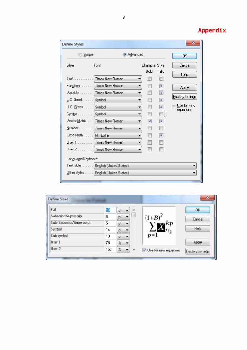
Microsoft Equation 3,0 programme must be used for formulae typing. Formulae styles and sizes you can define as it is show in Fig. 2 and Appendix.
a b
Fig. 2 Define of formulae: a – styles, b – sizes
The example how to type formulae inside one column is presented:
PM=0 . 4 Bb0
2 σY
2 W +a , (1)
where: spacing before – 10 pt, spacing after – 10 pt, Tab stop positions are 0.75 cm and 8.4 cm, respectively.
Text, Text, Text¸ Text, Text, Text, Text, Text, Text, Text, Text, Text, Text¸ Text, Text, Text, Text, Text, Text, Text, Text, Text, Text¸ Text, Text, Text, Text, Text, Text, Text.
The example how to type formulae inside two columns is presented:
2

f (ai /W )=(2+ai /W ) [0 . 866+4 .64 ai/W −13 .32 (a i/W )2+14 .72 (ai/W )3−5 . 6 (a i/W )4 ])
(1−ai/W )3 /2. (2)
For this case spacing before – 10 pt, spacing after – 10 pt, Tab stop positions are 8.7 cm and 17.4 cm, re-spectively.
4. Conclusions
We thank you in advance for the usage carefully of instructions for camera-ready articles, which can be sent for publication with minor modification. The example of article published in Mechanika is available at the Web Portal http://www.mechanika.ktu.lt/index.php/Mech/index.
References
1. Standard Test Method for Determining J-R Curves. ASTM E1152-87. 11p.
2. Jonaitis M.; Kamaitis P.; Rimaitis E. 1999. Deter-mining J-R curves of steam pipeline Du-630 welded joint materials in Ignalina NPP, Mechaninė technologija t.XXVII: 182-199 (in Russian).http://dx.doi.org/XX.XXX/(XXX)XX-
XX(XXX)X:X.3. Anderson, T.L. 1991. Fracture Mechanics. Fundamen-
tals and Applications.-Boca Raton, Ana Arbor: CRC Press. 793p.
4. Dickey, H.; Watson, V.; Zangelidis, A. 2009. Job satisfaction and quit intentions of offshore workers in the UK North Sea oil and gas industry [online] MPRA [accessed 9 Febr. 2010]. Available from Internet: http://mpra.ub.unimuenchen. de/18666/.
(Author’s) Name SURNAME, Name SURNAME, Name SURNAME
CAMERA-READY ARTICLES PREPARATION INSTRUCTIONS FOR “MECHANIKA” JOURNAL (ISSN 1392-1207)
S u m m a r y
Dear authors,Thank you for your interest in our journal. We
work hard to meet your expectations.
Keywords: keyword, keyword, keyword.
Received Month xx, xxxxAccepted Month xx, xxxx
Proceedings of 22nd International Conference “MECHANIKA 2017”Proceedings of 22nd International Conference “MECHANIKA 2017”
Fracture Toughness of Pipelines Welded Joints Materials
Mindaugas JONAITIS*, Petras KAMAITIS***Kaunas University of Technology, Kęstučio 27, 44025 Kaunas, Lithuania, E-mail: [email protected]**Kaunas University of Technology, Kęstučio 27, 44025 Kaunas, Lithuania, E-mail: [email protected]
1. Introduction
Exploitation of steam pipelines during start-up, hydraulic tests overloads and other emergencies, the strains reach dangerous values at times exceeding allowable lim-its. In most cases, such loads are met in the zones of stress concentration also cracks and welded joints zones. Increase of loading frequency in a set of forth, above dangerous zones, causes fast growth of fatigue crack in construction, resulting its failure. The evaluation of such situations needs to meet criteria of material resistance to crack growths as a characteristics of fracture.
Certain characteristics, such for example as frac-
ture toughness K1 C or J1C , crack resistance curves K−R or J−R and others criteria, on research of fracture, are used. In comparison of these relations, the plasticity resis-tance curve J−R is more preferable than separate charac-
teristics K1 C or J1C , because it shows the internal relation between stress and crack growth at all loading cases, and gives the opportunity of getting fracture toughness charac-
teristics J1C or K1 C from the same graphic.
The present work was carried out in order to ob-tain experimental data of fracture such as crack resistance
curves J−R
and fracture toughness characteristics K1 C
and J1C
on specimens made from steam pipelines DU-300 and DU-630 welded joint materials. Mechanical character-istics of pipes steel its weld and heat affected zone metals are shown in Table.
EXAMPLE
3

2. Testing proceduresTesting procedure of J−R curve is described in
the American standard ASTM E1152-87 [1]. In the major-ity of tests compact specimens C(T) for tension or B(T) for bending are applied. Compact specimens (Fig. 1) of differ-ent sizes are applied. The standard offers the following thickness of specimens: 1/2T, 1T, 2T and 4T, where T=25.4 mm. The specimens have three basic sizes: length of a crack a , thickness B and width W. In many cases there are accepted W=2В and а/W0.5. Basic sizes of spec-imens B and W-а should exceed the size of plastic zone in advance of a developing crack minimum 50 times, other-wise the incorrect characteristics of fracture toughness will be received. Sizes of the test specimens depend on the thickness of material, from which they are made. Speci-
mens of the size 1/2T and 1T have been used in our test, because the diameter of steam pipes.
Factor of load asymmetry in cycle during pre-cracking should not exceed r≤0 .1 and the length of a
crack should not be less than 5% from a0 , but not less than 1.3 mm. Beside the definition of J−R by the method of a compliance requires to observe condition 0 .5 <a0 /W <0 .75 , where a0 is the distance from loading
line up to the top of a crack. At a0/W <0. 5 the method of
compliance loses sensitivity, and at a0/W >0. 75 the plastic zone will be much more increased and becomes too
large. So, the ratio a0/W in our experiments varied within the limits 0.5-0.75.
TableMechanical characteristics of pipes main steel, weld and heat affected zone metal
Pipeline index
Pipe steel, weld and heat affected zone (HAZ) metal
Testtemperature
T, oC
Yield stress σ y , MPa
Ultimate
stress σ u ,MPa
Poisson’sratio
Young’smodulusE, MPa
DU-300 Steel 08X18N10T 20 309 608 0.35 140300285 232 397 0.35 140100
Weld metal welded manually and automati- 20 348 627 0.35 151800
4

cally by arc method with electrodes EА-100/10U or EА100/10T and wire metal Sv-
0419N11M3285
211
464 0.35 140400
Heat affected zone (HAZ) metal 20 283 584 0.35 151500285 240 474 0.35 188800
DU-630 Steel 16GS 20 265 572 0.37 174600285 198 645 0.37 142500
Weld metal welded manually and automati- 20 364 601 0.37 207100
5

cally by arc method with electrodesUONI 13/55 and wire metal Sv-08GS2 285
260 630
0.37 137400
6

Fig. 1 General view of a specimen with side grooves
All specimens were cyclically precracked on test-ing machine YPC-200 [2] at loading frequency 16-20 Hz at
load values PM . For C(T) specimens:
PM=0 . 4Bb0
2 σY
2 W +a , (1)
where: b0=W −a0 .The procedure of precracking in details is de-
scribed in [3].
3. Construction of J-R curves
The elastic compliance method using remote load line displacement measurements to develop J-R curve was carried out on a 250 kN tension-compression testing ma-chine, the loading speed during unloading - reloading cycle was taken about 40 seconds [4].
An experimental definition of J-R curves (Fig. 2, curve 4) was investigated on specimens, made of pipes steel, weld and heat affected zone metal [4]. Schemes of cutting specimens are shown in Fig. 1.
Fig. 2 J-R curve for steel 16GS at T=285°C, crack limits and the exclusion line: 1, 2, 3 – experimental re-sults; 4 – theoretical curve
The J integral values ware calculated at all points of “load-versus-displacement” record using the equation:
J=J e+J p , (2)
where: Je is elastic part and J p is plastic part of J integ-ral.
For any cycle i of unloading – reloading se-
quence with coordinates Pi , δ i and current crack length a i :
J i=( K i)2 (1−γ 2)
E +J pi
, (3)
where:
(4)
and ηi =2.0+0.5222 b i /W ; γi=1. 0+0 . 76 bi /W .
f (ai /W )=(2+ai /W ) [0 . 866+4 .64 ai/W −13 .32 (a i/W )2+14 .72 (ai/W )3−5 . 6 (a i/W )4 ])
(1−ai/W )3 /2. (5)
By the method of compliance construction J-R curve does not require crack’s length measurement during the test, because the crack length is given from ratio a i/W which equal [5]:
(6)
where: Be=B−(B−BN )2 /B .In order to account the crack opening displace-
ment in C(T) specimens for its rotation compliance was
corrected, new values of J i and a i were calculated and
J−R curvesJ i versus a i were plotted [6].An example of calculated J−R curve at T=285°C
for specimen cut from pipe DU-630 steel 16GS. Averaged J-R curves for welded specimens in series cut from pipe DU-300 at elevated (T=285°C) temperature.
4. Conclusions
1. Fracture toughness research has shown that side grooves on the specimens are necessary to receive
straight crack front and initial ratio 0 . 55≥a0/W ≤0 . 65 is preferable to give excellent sensivity of compliance mea-surement.
EXAMPLE
7
2. Comparison of J−R curves using two meth-
ods has shown that J1C integral values for all investigated metals are similar, except steel 16GS at normal
, elevated tem-perature and pipe’s DU-300 weld metal
and varies from 73 to 88 kN/m.
3. Maximum K1 C values were for steel 08X18H10T, its weld and steel 16GS at normal tempera-
ture , minimum – for steel 08X18H10T at elevated (285°C) temperature
. For other metals temperature
of testing has not significant influence on K1 C values and
were in the range K1 C =109.1-131.8 MPa√m .
References
5. Standard Test Method for Determining J-R Curves. ASTM E1152-87. 11p.
6. Jonaitis M.; Kamaitis P.; Rimaitis E. 1999. Deter-mining J-R curves of steam pipeline Du-630 welded joint materials in Ignalina NPP, Mechaninė technologija t.XXVII: 182-199 (in Russian).http://dx.doi.org/XX.XXX/(XXX)XX-
XX(XXX)X:X.7. Standard Test Method for J IС , a Measure of Fracture
Toughness. Philadelphia, ASTM E813-87.8. Anderson, T.L. 1991. Fracture Mechanics. Fundamen-
tals and Applications.-Boca Raton, Ana Arbor: CRC Press. 793p.
9. Bražėnas, A.; Daunys, M. 1995. The stress strain state and plasticity of mechanically heterogeneous welded joints with a flat interlayer subjected to tension (com-pression), Mechanika 17(1): 5-13.http://dx.doi.org/XX.XXX/(XXX)XX-
XX(XXX)X:X.10. Daunys M. 1989. Strength and Fatigue Life under Low
Cycle Non-Stationary Loading. Vilnius: Mokslas. 256p (in Russian).
11. Dickey, H.; Watson, V.; Zangelidis, A. 2009. Job satisfaction and quit intentions of offshore workers in the UK North Sea oil and gas industry [online] MPRA [accessed 9 Febr. 2010]. Available from Internet: http://mpra.ub.unimuenchen. de/18666/.
M. Jonaitis, P. Kamaitis
FRACTURE TOUGHNESS OF PIPELINES WELDED JOINTS MATERIALS
S u m m a r y
This paper presents the investigation of fracture toughness of welded joint materials of steam pipelines DU-300 and DU-630 used in Ignalina NPP. Main pipes metal – 08X18N10T (DU-300), 16GS (DU-630), its weld metal welded manually and automatically by arc method with electrodes UONI 13/55, EA-100/10U or EA-100/10T using wire SV-08GS2 and SV-0419N11M3, also pipe DU-300 heat affected zone metal was tested. Sharp fatigue cracks in compact specimens were initiated and using compliance testing method crack resistance J−R curves were develo-
ped, critical values of J integral J 1C and stress intensity
factor K1 C at normal (20oC) and elevated (285oC) tem-peratures were also obtained.
Keywords: fracture toughness, welded joints materials.
Received March 20, 2014Accepted February 02, 2015
EXAMPLE
8

Appendix
9