fracture toughness of hdpe evaluated by fatigue and … · 2015-06-01 · recommended in metals...
TRANSCRIPT
Proceedings of the 6th International Conference on Mechanics and Materials in Design,
Editors: J.F. Silva Gomes & S.A. Meguid, P.Delgada/Azores, 26-30 July 2015
-1737-
PAPER REF: 5463
FRACTURE TOUGHNESS OF HDPE EVALUATED BY FATIGUE AND
NOTCH PRECRACKING
Luis Fernando Iglésias1, Thais P. Sequeira
1, Marysilvia F. Costa
1, Celio A. Costa
1(*)
1Metallurgical & Materials Engineering Department (POLI/COPPE/UFRJ), Universidade Federal do Rio de
Janeiro (UFRJ), Rio de Janeiro, Brazil (*)Email: [email protected]
ABSTRACT
The present study compares the fracture toughness properties of high density polyethylene
(HDPE) when the precrack was opened by razor blade and by fatigue. Razor blades were
prepared with two different radius of curvature, while the fatigue precracking had the radius
of curvature close to zero, as demanded by fracture mechanics concept. In addition, side
grooved machined samples were evaluated with razor blade precrack opening. The KIC results
for the razor blade tests were 1.57 MPa.m1/2 and 2.42 MPa.m
1/2, depending on the radius of
curvature of selected razor blade. For the fatigue precracking, it was 0.57 MPa.m1/2. Likewise,
KIC results for side grooved machined specimens were 0.97 MPa.m1/2 and 1.67 MPa.m
1/2
respectively for selected razor blades. This discrepancy confirms that fatigue precracking
showed a much lower value for fracture toughness than the razor blade notch opening. It is
also proposed that fatigue precracking in polymers should be further investigated as a regular
procedure to be included in standards. Fractography investigation was realized and micro
mechanisms of precrack opening methods were discussed.
Keywords: Fracture Mechanics, polymer, HDPE, precracking methodology.
INTRODUCTION
Applications of polymeric materials have been increasing in structural components. For
instance, their applications in pipes as thermoplastic jackets or pressure barrier in flexible pipe
risers are quite common nowadays. Fracture mechanics has been largely used to measure the
fracture toughness of structural materials and, due to the use of polymers in high demand
applications, high concern has been raised about the correct use of this methodology for a
viscoelastic material. One topic that has been addressed recursively is the precrack opening
methodology [1,2,3], since a curvature radius close to zero is desirable.
In metals, precrack opening is easily conducted with controlled cyclic load and standards for
that are well stablished. For viscoelastic materials, as polymers, cycling becomes a difficult
task since creep/stress relaxations acts during the fatigue, and the determination of the glass
transition temperature (Tg) is very important [3]. To circumvent this problem, the ASTM
D5045 recommends the precracking method by a razor blade, which shall lead to a radius of
curvature with the same stress intensity factor as the one generated by fatigue. Care shall be
taken not to damage the material ahead of the notch, either by strain hardening or elevated
temperature due to friction.
Chan and Williams [2] have shown that the razor blade simulates neither an ideal crack plane
nor the sharpest possible crack tip; also, the blade can cause damage to the polymeric matrix
and, therefore, it shall lead to interference in fracture test results. However, fatigue precrack

Symposium_17
Mechanical Behaviours of Advanced Materials and Structures at All Scales
-1738-
opening methodology requires more controllable parameters as polymers are viscoelastic
materials and therefore precracking by fatigue has not been an easy process. Discussions
about the difference between fracture mechanics parameters and results using a razor blade
and fatigue precracking do not seem to have been addressed for HDPE at this moment.
The aim of this study is is to evaluate the KIC results between fatigue precrack and razor blade
notching opening conditions that lead to an acceptable crack considering ASTM D5045, as
recommended in metals standard (ASTM E399), with focus in a zero radius of curvature at its
tip. In addition, side groove notches will be notched in samples with razor blade precrack
opening in order to evaluate and compare this effect in KIC results. Finally, Scanning Electron
Microscopy (SEM) investigation was performed in specimens fractured surfaces and micro
mechanisms involved in precrack opening conditions were observed and discussed.
EXPERIMENTAL PROCEDURE
The material investigated was a commercial grade high density polyethylene (HDPE). This
material was selected because of its process simplicity, low cost and wide use and
applications. Specimens for fracture tests according to ASTM D5045 (Figure 1) were
machined with 25.5 mm thickness. Dimensions are shown in Figure 2-A and Figure 2-B. Side
grooves were introduced in some CT samples.
Fig. 1 - Specimens for fracture tests.
Fig. 2 - Dimensions of Compact Tension (CT). Figure 1-A shows specimens without side grooves (CT
specimens) and Figure 1-B presents side grooved specimens CT specimens.
Side
Grooves

Proceedings of the 6th International Conference on Mechanics and Materials in Design,
Editors: J.F. Silva Gomes & S.A. Meguid, P.Delgada/Azores,
Fatigue precrack opening was performed by a servo
displacement-control with sinusoidal waveform and respective fatigue conditions: minimum
to-maximum load ratio R = 0.1, frequency f = 10 Hz (close to material’s glass transition) and
6000 cycles in stepwise fatigue crack opening mode. A small cut with a
side of the notch tip was necessary to reduce the plain stress state at border of the CT sample
and the tunneling effect [3].
Two different razor blades named 1 and 2 were used to open the precracks in the samples and
are represented in Figure 3. Note that blade 1 visually appears to be sharper than blade 2 and,
consequently, it has a lower value of curvature radius. Furthermore, precracks were opened in
side groove notched specimens using blades 1 and 2.
Fig. 3
Just after the precrack opening, either by fatigue or razor blade, dye penetrant liquid was
sprayed into the pre-cracks with specimens placed with the notch opening up for 15 minutes.
This technique marked the prec
CT precracked samples were tested per ASTM D5045 to verify if they match the plain strain
fracture toughness state. The tests were conducted in a MTS Landmark® machine. The
method used for measuring precr
it was performed by a Nikon profile projector Model 6C 12666 after fracture tests.
Final fatigue opened precracks mean length values were determined as 4.9 mm. For razor
blade opened precracks, a mean
specimens. These precrack dimensions are consistent with ASTM D5045 standard according
to specimen thickness (25.5 mm).
The fracture surface images obtained after fracture tests were obtained by SE
2000 FX model and precrack opening characteristics and micro mechanisms of crack opening
and propagation were observed.
(1)
Proceedings of the 6th International Conference on Mechanics and Materials in Design,
Editors: J.F. Silva Gomes & S.A. Meguid, P.Delgada/Azores, 26-30 July 2015
-1739-
Fatigue precrack opening was performed by a servo-hydraulic MTS Landmark®, using
control with sinusoidal waveform and respective fatigue conditions: minimum
R = 0.1, frequency f = 10 Hz (close to material’s glass transition) and
6000 cycles in stepwise fatigue crack opening mode. A small cut with a razor blade at the end
side of the notch tip was necessary to reduce the plain stress state at border of the CT sample
Two different razor blades named 1 and 2 were used to open the precracks in the samples and
in Figure 3. Note that blade 1 visually appears to be sharper than blade 2 and,
consequently, it has a lower value of curvature radius. Furthermore, precracks were opened in
side groove notched specimens using blades 1 and 2.
. 3 - Razor blades used for precrack opening.
Just after the precrack opening, either by fatigue or razor blade, dye penetrant liquid was
cracks with specimens placed with the notch opening up for 15 minutes.
This technique marked the precrack boundaries, making visual observation easier.
CT precracked samples were tested per ASTM D5045 to verify if they match the plain strain
fracture toughness state. The tests were conducted in a MTS Landmark® machine. The
method used for measuring precrack lengths was adapted from ASTM D6068 procedure and
it was performed by a Nikon profile projector Model 6C 12666 after fracture tests.
Final fatigue opened precracks mean length values were determined as 4.9 mm. For razor
blade opened precracks, a mean value of 5.0 mm length was obtained in side grooved or not
specimens. These precrack dimensions are consistent with ASTM D5045 standard according
to specimen thickness (25.5 mm).
The fracture surface images obtained after fracture tests were obtained by SE
2000 FX model and precrack opening characteristics and micro mechanisms of crack opening
and propagation were observed.
(1) (2)
hydraulic MTS Landmark®, using
control with sinusoidal waveform and respective fatigue conditions: minimum-
R = 0.1, frequency f = 10 Hz (close to material’s glass transition) and
razor blade at the end
side of the notch tip was necessary to reduce the plain stress state at border of the CT sample
Two different razor blades named 1 and 2 were used to open the precracks in the samples and
in Figure 3. Note that blade 1 visually appears to be sharper than blade 2 and,
consequently, it has a lower value of curvature radius. Furthermore, precracks were opened in
Just after the precrack opening, either by fatigue or razor blade, dye penetrant liquid was
cracks with specimens placed with the notch opening up for 15 minutes.
rack boundaries, making visual observation easier.
CT precracked samples were tested per ASTM D5045 to verify if they match the plain strain
fracture toughness state. The tests were conducted in a MTS Landmark® machine. The
ack lengths was adapted from ASTM D6068 procedure and
it was performed by a Nikon profile projector Model 6C 12666 after fracture tests.
Final fatigue opened precracks mean length values were determined as 4.9 mm. For razor
value of 5.0 mm length was obtained in side grooved or not
specimens. These precrack dimensions are consistent with ASTM D5045 standard according
The fracture surface images obtained after fracture tests were obtained by SEM using a JOEL
2000 FX model and precrack opening characteristics and micro mechanisms of crack opening

Symposium_17
Mechanical Behaviours of Advanced Materials and Structures at All Scales
RESULTS
Samples had their precracks opened by a razor blade in CT specimens and CT side grooved
specimens and the results were compared with the data for a fatigue precrack procedure [3]
and with literature [1,4,5,6] concerning K
methodologies is shown in Figure 4
are presented in Figure 4-D. The razor blade crack is straight, while the fatigue crack has a
nail shape, where tunnelling can be observed. The K
0.0
0
200
400
600
800
1000
1200
1400
Axial Force (N)
(D) Load-displacement curves from K
Fig. 4 - Precracks front zones (Figures 4
Fatigue precracking
(A)
SEM analysis
(1)
Mechanical Behaviours of Advanced Materials and Structures at All Scales
-1740-
Samples had their precracks opened by a razor blade in CT specimens and CT side grooved
ts were compared with the data for a fatigue precrack procedure [3]
and with literature [1,4,5,6] concerning KIC toughness results. The crack front for these
methodologies is shown in Figure 4-A to 4-C and their respective curves of load
D. The razor blade crack is straight, while the fatigue crack has a
nail shape, where tunnelling can be observed. The KIC results are listed in Table 1 for HDPE.
0.5 1.0 1.5 2.0
Fatigue precrack
Razor blade precrack
Razor blade precrack
(side grooved specimens)
Axial Displacement (mm)
displacement curves from KIC test record in 3 different precrack opening methods.
Precracks front zones (Figures 4-A to 4-C) and respective fracture toughness test record (Figure 4
Razor blade with side grooves
(B) (C)
SEM analysis
(2)
Samples had their precracks opened by a razor blade in CT specimens and CT side grooved
ts were compared with the data for a fatigue precrack procedure [3]
toughness results. The crack front for these
C and their respective curves of load-displacement
D. The razor blade crack is straight, while the fatigue crack has a
results are listed in Table 1 for HDPE.
2.5
Fatigue precrack
Razor blade precrack
Razor blade precrack
(side grooved specimens)
test record in 3 different precrack opening methods.
C) and respective fracture toughness test record (Figure 4-D).
Razor blade
with side grooves
SEM analysis
(3)

Proceedings of the 6th International Conference on Mechanics and Materials in Design,
Editors: J.F. Silva Gomes & S.A. Meguid, P.Delgada/Azores, 26-30 July 2015
-1741-
In Table 1, the KIC results for razor blades 1 and 2 were similar to those reported in the
literature by Baterzak et al. [4] in similar conditions and it was 276% and 424% higher,
respectively, than the one calculated when fatigue precracking was the method used by
Sequeira [3]. Note that Ulmanu et al. [1] reported a KIC value using fatigue precrack opening
in stepwise fatigue mode with side grooves notches, frequency of 5 Hz and R = 0.1. This is
approximately 30% higher than the value obtained by Sequeira [3].
Literature reports other results in different test conditions. For example, Andreassen and Nord
have demonstrated that in impact conditions the KIC value was calculated as 1.66 MPa.m1/2
exihibiting a higher strain rate than the results presented in this work. Plati and Willians have
performed fracture tests in cryogenic conditions (T= -63oC) and KIC value was calculated as
1.00 MPa.m1/2. Note that in this condition, the material is closer to the glass transition. It’s
assumed that these results were obtained by razor blade precracking since the authors do not
present this specific information.
For curvature radius closer to zero, results are more conservative. Therefore, KIC calculation
depends tightly of precrack opening methodology and also by test conditions (temperature
and strain rate).
Table 1 - KIC results and selected methodology.
Precrack opening
Methodology
Calculated KIC
Toughness (MPa. m1/2)
CT sample
Razor blade 1 1.57
CT sample
Razor blade 2 2.42
Side grooved CT
Razor blade 1 0.97
Side grooved CT
Razor blade 2 1.67
Sequeira et al. [3]
(fatigue opening) 0.57
Ulmanu et al. [1]
(fatigue opening) 0.74
Baterzak et al. [4]
(razor blade opening) 2.05
Andreassen and Nord [5]
(impact condition) 1.66
Plati and Willians [6]
(cryogenic conditions) 1.00
Fractography investigation was conducted and images from specimens surfaces after fracture
tests and regions were selected for observation which are shown in Figures 4-A to 4-C. The
analysis allowed observing distinct micro mechanisms due to precrack nucleation and growth.
Three different regions were observed in Figure 4-A to 4-C for each type of methodology for
evaluating KIC: CT sample with precrack opening by fatigue (1); CT sample with precrack
opened by razor blade (2); side grooved CT sample with precrack opened by razor blade (3).
Symposium_17
Mechanical Behaviours of Advanced Materials and Structures at All Scales
-1742-
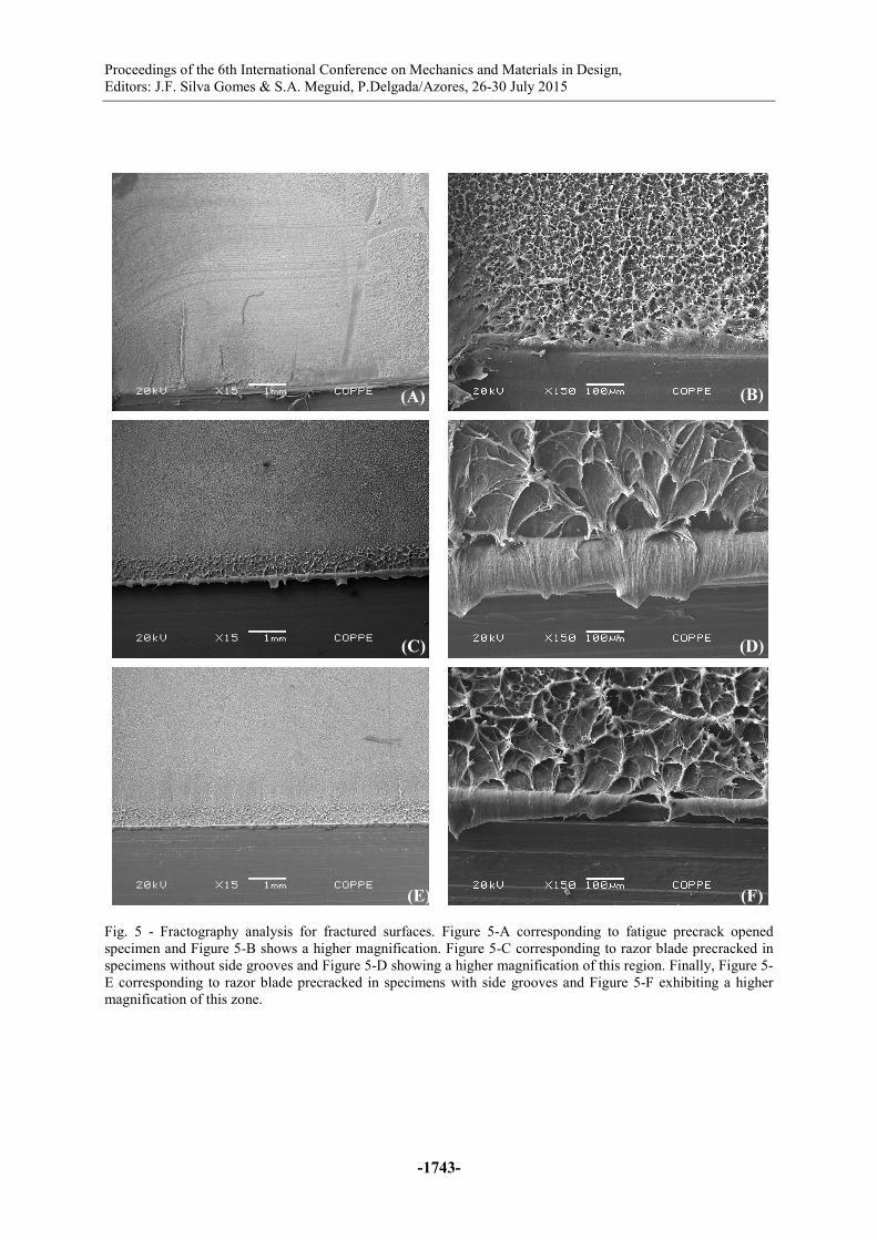
Fractography analysis is presented in Figures 5-A to 5-F. The micro mechanisms involved in
precrack growth during fatigue cycling are the generation of beach marks and crazing process
followed by severe plastic deformation due to crack propagation.
Figure 5-A and 5-B exhibits the characteristics fractured surfaces. It can be noted the presence
of the tunneling effect because of a large difference in stress states along the notch/crack
front. At the notch borders there is always a plane stress state, while in the middle zone a
plane strain exists. In polymers, which are viscoelastic materials, this difference may be very
high and tunneling then happens with more intensity in samples borders than in metals and
this is not allowed for corrected KIC computation. Crazes can be observed during crack
propagation. After tunneling zone, severe plastic deformation by crazing deformation occurs.
It’s evident the presence of fibrils due to the coalescence of cracks and molecular
reorganization. Crack propagation continues by the rupture of fibrils and the creation of new
surfaces and cavities.
In Figures 5-C to 5-F, the characteristics due to razor blade crack opening in specimens with
or without side grooves are similar. It’s observed a smooth region corresponding to razor cut
followed by a cut zone as a consequence of machining process. Finally, during severe plastic
deformation, a plastic zone appears which is characterized by the formation of fibrils. Note
that the magnitude and size of cavities and fibrils just after the cut zone is higher than those
fibrils from fatigue crack tip. The formation of fibrils and cavities size was related to the level
of stress concentration, so as to, the smaller cavity size was present in the fatigue precracking,
and increased for side groove and razor blade.
In Figure 6-A, the fatigue precracked specimens, it is evident the transition region between a
smooth path and a plastic deformation zone characterized by fibrils and cavities. Figure 6-B
shows the region located in the center of the precrack. Note the existing paths distributed in a
non-homogeneous mode. This effect is expected as the specimen was cycled in stepwise
fatigue mode [3] and in order to maintain the R value constant during the test, the material
was reloaded whenever the material presented a relaxation behavior due to its viscoelastic
properties.
CONCLUSION
The present study showed that fatigue precracking can be a regular method for fracture
toughness tests. The fatigue precracking was opened in a fast and controlled manner, resulting
in the lowest KIC measured. The presence of side grooves in razor blade precrack method
increased the plain state of stress, but the result was higher than that the fatigue precracking.
The KIC measured by razor blade showed the highest value measured.
A precracking method to evaluate polymers needs to be further evaluated and better defined
in the standards, since the scatter in the results is large.
ACKNOWLEDGMENTS
The author would like to thanks to the Brazilian National Petroleum Agency (ANP), through
PRH 35, for supporting this research.
Proceedings of the 6th International Conference on Mechanics and Materials in Design,
Editors: J.F. Silva Gomes & S.A. Meguid, P.Delgada/Azores, 26-30 July 2015
-1743-
Fig. 5 - Fractography analysis for fractured surfaces. Figure 5-A corresponding to fatigue precrack opened
specimen and Figure 5-B shows a higher magnification. Figure 5-C corresponding to razor blade precracked in
specimens without side grooves and Figure 5-D showing a higher magnification of this region. Finally, Figure 5-
E corresponding to razor blade precracked in specimens with side grooves and Figure 5-F exhibiting a higher
magnification of this zone.
(A) (B)
(C) (D)
(E) (F)

Symposium_17
Mechanical Behaviours of Advanced Materials and Structures at All Scales
-1744-
Fig. 6 - In Figure 6-A, note the transition between the precrack fatigue zone and severe plastic deformation by
crack propagation where tunneling effect can be observed. In Figure 6-B, beach marks are shown in fatigue
precrack center region generated by stepwise fatigue opening mode.
REFERENCES
[1]-Ulmanu, V.; Draghici, G., Aluchi, V. Mechanics Testing High Density Polyethylene
(HDPE) Pipe Material with Compact Tension (CT) Specimens, Journal of Engineering
Studies and Research – Volume 17 (2011) No. 3.
[2]-Chan, M.K.V. and Williams, J.G. Plane Strain Fracture Toughness Testing of High
Density Polyethylene; Polymers Engineering & Science; pp 1019 -1026, October 1981.
[3]-Sequeira T., Costa M., Costa C. Fatigue Precracking Methodology for HDPE,
Proceedings of the ASME 2014 33rd International Conference on Ocean, Offshore and Arctic
Engineering.
OMAE2014, June 8-13, 2014 (paper OMAE2014-24692).
[4]-Argon, A. S.; Bartezak, Z.; Cohen, R.E.; Muratoglu, O.K., “Novel mechanism of
toughening of plastics, advances in modeling and experiments,” vol. 42, n. 759, Washington
D.C., ACS, p. 2347, 2000.
[5]-Andreassen; Nord-Varhaug; Hinrichsen; Persson, “Impact fracture toughness of
polyethylene materials for injection moulding,” em PPS07EA, Gothenburg, 2007.
[6]-Plati, E.; Willians, J.C., “Effect of temperature toughness of polymers,” Polymer
Engineering Science, vol. 16, n. 915-920, 1975.
(A) (B)