fracture propagation in dense phase co2 pipelines from an ... · fracture control/fracture...
TRANSCRIPT

SYMPOSIUM SERIES NO 161 HAZARDS 26 © 2016 IChemE
1
Fracture Propagation in Dense Phase CO2 Pipelines from an Operator’s
Perspective
Russell Cooper & Julian Barnett, National Grid Carbon, Solihull, UK.
Carbon Capture and Storage (CCS) is an approach adopted in order to mitigate global warming by capturing carbon dioxide (CO2) from large industrial sources and storing it safely instead of releasing it into the
atmosphere. Pipelines can be expected to play a significant role in the transportation of CO2 for CCS.
National Grid has extensive experience in pipeline transportation and is supporting the development of CCS. National Grid is undertaking a comprehensive research programme to support the development of a safety
justification for the design, construction and operation of pipelines for CO2 transportation in the United
Kingdom (UK).
National Grid is pursuing plans to develop a pipeline network in the Humber and Yorkshire areas of the UK to
transport dense phase CO2 from major industrial emitters to a saline aquifer beneath the North Sea. The ‘Yorkshire and Humber CCS project’ as it is called includes a 67 kilometre long, 600 mm (24”) diameter
onshore pipeline and a 90 kilometre long, 600 mm (24”) diameter offshore pipeline.
Pipelines transporting CO2 are susceptible to long running fractures which are prevented by specifying an adequate pipe body toughness to arrest the fracture. There is no existing, validated methodology for setting pipe
body toughness levels for pipelines transporting dense phase CO2 with impurities. The methods for estimating
the pipe body toughness are semi-empirical so full scale fracture propagation tests are required to validate and
extend these methods.
National Grid has already conducted two full scale fracture propagation tests using 900 mm (36”) diameter
pipe. The tests showed that current natural gas practice for setting pipe body toughness levels is not directly applicable to dense phase CO2 as it was incorrect and non-conservative. National Grid recognises the
importance of understanding fracture arrest as it impacts on pipeline design, provides reassurance to key
stakeholders (e.g. Health and Safety Executive) and is required to ensure compliance with pipeline design codes.
As the results of the two tests could not be used to set the toughness requirements for the Yorkshire and
Humber CCS project, a third full scale test was necessary to confirm the fracture arrest capability of the pipe for the proposed pipelines.
A third full scale fracture propagation test was conducted on 25th July 2015 at the DNV GL, Spadeadam Test &
Research Centre, UK. A propagating ductile fracture was initiated and successfully arrested in line pipe representative of that to be used on the proposed project.
The paper provides an overview of the third full scale fracture propagation test, the results and the implications
to the Yorkshire and Humber CCS project.
Introduction
The COOLTRANS research programme was carried out to identify, address and resolve key issues relating to the safe
routeing, design, construction and operation of onshore pipelines transporting dense phase carbon dioxide (CO2) in the
United Kingdom (UK). National Grid established and led the research programme, and has used the results in its
consideration of the development of a potential cross country pipeline in the Humber and North Yorkshire area of the UK to
transport dense phase CO2 from major industrial emitters in the area to a saline aquifer off the Yorkshire coast under the
North Sea.
Dense phase CO2 is a hazardous substance, so a pipeline transporting dense phase CO2 must comply with UK safety
legislation, and so must be designed in accordance with the requirements of recognised codes and standards. The hazards
posed by CO2 fall into two main categories:
i) Hazards to people, CO2 is toxic and is an asphyxiant.
ii) Hazards to pipeline integrity, CO2 is corrosive in the presence of water, pipelines are susceptible to long running
propagating fractures in the unlikely event of a failure resulting in a rupture.
In order to mitigate and minimise these hazards, the key design requirements in place in pipeline design codes are:
Routeing to minimise the risks posed to people;
Consideration of the pipeline’s design factor to control the failure mode of any damage incurred;
Corrosion protection to minimise the occurrence of corrosion;
Fracture control to avoid propagating fractures;
The Don Valley CCS Project is co-financed by the European Union’s European Energy Programme
for Recovery. The sole responsibility for this publication lies with the authors. The European Union is not responsible for any use that may be made of the information contained therein.

SYMPOSIUM SERIES NO 161 HAZARDS 26 © 2016 IChemE
2
Ongoing maintenance, inspection and monitoring.
The application of all of the above requirements to dense phase CO2 pipelines and others not listed here has been
investigated. This paper presents the research undertaken to identify the fracture control requirements for the prevention of
propagating fractures in pipelines transporting dense phase CO2.
Fracture control/Fracture Propagation in Pipelines
Fracture control is an integral part of the design of a pipeline, and is required to minimise both the likelihood of failures
occurring (fracture initiation control) and to prevent or arrest long running brittle or ductile fractures (fracture propagation
control).
As part of the COOLTRANS research programme, National Grid reviewed the findings of the work carried out in the 1970s
and 1980s on natural gas pipelines, applied the learning to CO2 pipelines and, extended and verified where necessary
through analysis and experiments, in order to develop reasonable, practical requirements.
Fracture initiation is associated with the critical through wall (axial) length of a defect which will result in a rupture, and is
dependent upon the pipe geometry, material properties and operating stress. Fracture propagation occurs when a failure
results in rupture and then the energy released by the fluid is greater than the resistance of the steel to running fractures.
Fracture control requirements are specified in design in terms of:
a) The minimum Ductile-Brittle Transition Temperature (DBTT) of the material in order to prevent brittle fracture.
This is confirmed by specifying appropriate Drop Weight Tear Test (DWTT) requirements (i.e. minimum 85%
shear area at the minimum design temperature of the pipeline).
b) The minimum toughness requirements (i.e. minimum upper shelf Charpy V-notch impact value) to prevent and/or
arrest ductile fracture propagation.
The above requirements are well understood and apply to pipelines transporting any fluid, including dense phase CO2.
However the methods for determining the toughness requirements to arrest a propagating ductile fracture are semi-empirical,
and have not been validated for application to dense phase CO2 pipelines. The approach taken to investigate this is
considered in the following section.
COOLTRANS Research into Toughness Requirements for Fracture Arrest in Dense Phase CO2
Pipelines
Line pipe specifications referenced in pipeline design codes, such as BS EN ISO 3183:2012 [BSI 2012], include minimum
toughness requirements to ensure that the line pipe will fracture in a ductile manner and that the toughness of the line pipe
steel (pipe body) is sufficiently high to arrest a ductile fracture within an acceptable number of pipe lengths (i.e. one to three)
with a specified confidence level (e.g. 95%). Similarly, specifications for welds, fittings, etc. include toughness
requirements to ensure that the material is ductile under design conditions.
Toughness requirements for line pipe are expressed in terms of the shear area measured in a DWTT test and the upper-shelf
impact energy measured in a Charpy V-notch (CVN) test [Cosham et al, 2009]. The DWTT requirement ensures that the
line pipe will fail in a ductile manner and it prevents brittle fracture propagation. The CVN requirement ensures that a
running ductile fracture will either not occur or will arrest within a short distance. Toughness requirements preventing
running fractures only need to be considered for the pipe body.
The toughness required to prevent brittle fracture propagation is independent of the fluid being transported in the pipeline,
while the toughness required to prevent ductile fracture propagation is dependent on the fluid being transported in the
pipeline.
The strategy adopted in determining the toughness requirements for CO2 pipelines was to apply existing methods proven for
natural gas pipelines, recognise the differences between natural gas and dense phase CO2 and CO2 mixtures, and confirm the
application through experimental research. In terms of fracture propagation, the major differences between natural gas and
dense phase CO2 is the decompression behaviour and specifically the long plateau in the decompression curve. Running
fractures travel at very high speeds, typically over 100 m/s. The fluid temperature will drop significantly during
decompression, but the speed of the fracture is too high for these low temperatures to affect the running fracture.
Application of the Battelle Two Curve Model
The established model for predicting the arrest toughness for natural gas pipelines is the semi-empirical Battelle Two Curve
Model (TCM), Figure 1. The TCM was developed by the Battelle Memorial Institute in the 1970s [Maxey 1974, Eiber et al,
1993], and has been validated through a range of full scale tests on lean and rich gases.

SYMPOSIUM SERIES NO 161 HAZARDS 26 © 2016 IChemE
3
Figure 1 The Two Curve Model
The TCM is a general model which assumes that the decompression behaviour and the dynamic crack propagation behaviour
are uncoupled processes. The two curves are a model of the fracture propagating through the steel and a model of the
decompression behaviour of the fluid. Models which have been developed to predict the decompression behaviour of dense
phase CO2 include DECOM [Cosham, 2010]. DECOM is based on GASDECOM, developed for lean and rich gases, but it
uses an equation of state more appropriate to CO2 and CO2 rich mixtures. Predictions obtained using this model were
validated in the COOLTRANS research programme.
The overall strategy to validate the application of the TCM to liquid or dense phase CO2 pipelines involved:
i. conducting initial calculations of the minimum required toughness levels and the trends with pressure, temperature
and composition;
ii. establishing a high confidence in these initial results through shock tube testing to better understand the
decompression behaviour; and,
iii. validation of the predictions through full scale fracture propagation tests.
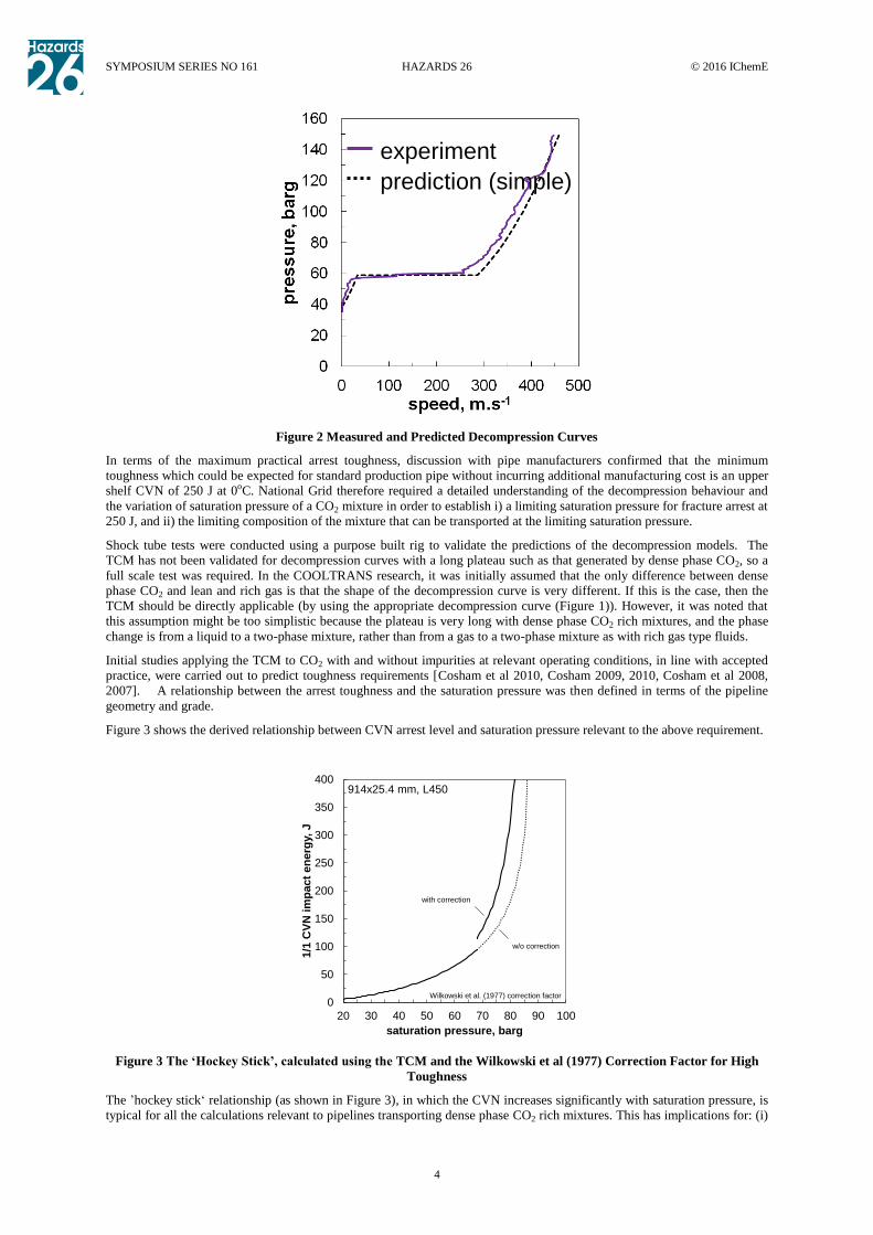
The decompression models predict a long ‘plateau’ in the decompression curve at the ‘saturation pressure’. This has been
confirmed by published tests on CO2 [5,6] and the shock tube tests carried out by National Grid [Cosham et al, 2012], Figure
2. The long plateau in the decompression curve indicates that the toughness required to arrest a running ductile fracture (the
arrest toughness) in a pipeline transporting dense phase CO2 corresponds to the condition when the ‘saturation pressure’ is
equal to the ‘arrest pressure’. This is a simplifying assumption and it is conservative. The arrest toughness depends on the
‘saturation pressure’, because of the long plateau, which in turn depends on the pressure, temperature and CO2 composition.
The saturation pressure, and hence the toughness required to arrest a fracture, increases as the initial temperature increases,
the initial pressure decreases or as the concentration of some impurities increases.
SYMPOSIUM SERIES NO 161 HAZARDS 26 © 2016 IChemE
4
Figure 2 Measured and Predicted Decompression Curves
In terms of the maximum practical arrest toughness, discussion with pipe manufacturers confirmed that the minimum
toughness which could be expected for standard production pipe without incurring additional manufacturing cost is an upper
shelf CVN of 250 J at 0oC. National Grid therefore required a detailed understanding of the decompression behaviour and
the variation of saturation pressure of a CO2 mixture in order to establish i) a limiting saturation pressure for fracture arrest at
250 J, and ii) the limiting composition of the mixture that can be transported at the limiting saturation pressure.
Shock tube tests were conducted using a purpose built rig to validate the predictions of the decompression models. The
TCM has not been validated for decompression curves with a long plateau such as that generated by dense phase CO2, so a
full scale test was required. In the COOLTRANS research, it was initially assumed that the only difference between dense
phase CO2 and lean and rich gas is that the shape of the decompression curve is very different. If this is the case, then the
TCM should be directly applicable (by using the appropriate decompression curve (Figure 1)). However, it was noted that
this assumption might be too simplistic because the plateau is very long with dense phase CO2 rich mixtures, and the phase
change is from a liquid to a two-phase mixture, rather than from a gas to a two-phase mixture as with rich gas type fluids.
Initial studies applying the TCM to CO2 with and without impurities at relevant operating conditions, in line with accepted
practice, were carried out to predict toughness requirements [Cosham et al 2010, Cosham 2009, 2010, Cosham et al 2008,
2007]. A relationship between the arrest toughness and the saturation pressure was then defined in terms of the pipeline
geometry and grade.
Figure 3 shows the derived relationship between CVN arrest level and saturation pressure relevant to the above requirement.
Figure 3 The ‘Hockey Stick’, calculated using the TCM and the Wilkowski et al (1977) Correction Factor for High
Toughness
The ’hockey stick‘ relationship (as shown in Figure 3), in which the CVN increases significantly with saturation pressure, is
typical for all the calculations relevant to pipelines transporting dense phase CO2 rich mixtures. This has implications for: (i)
0
50
100
150
200
250
300
350
400
20 30 40 50 60 70 80 90 100
1/1
CV
N i
mp
act
en
erg
y,
J
saturation pressure, barg
Wilkowski et al. (1977) correction factor
914x25.4 mm, L450
w/o correction
with correction
experiment
prediction (simple)

SYMPOSIUM SERIES NO 161 HAZARDS 26 © 2016 IChemE
5
operation close to the region (vertical) where arrest toughness is highly sensitive to very small changes in saturation pressure
which is undesirable as there is a credible risk of long running fracture and (ii) the specification of a suitable factor of safety
(i.e. reduction in allowable saturation pressure) so the operator has an acceptable safety margin against long running fracture.
A parametric study [Cosham, 2012] was conducted to define a simple relationship between the saturation pressure and the
pressure, temperature and level of impurities. This facilitated the development of simple design rules to quantify the
toughness requirements for a range of pipeline geometries, grades and operating conditions (pressure, temperature and
composition). A full scale fracture propagation test was required to validate these toughness requirements, because they are
based on a TCM that has not been validated for CO2 pipelines.
Experimental Research into Fracture Arrest
Full scale tests to investigate shear fracture propagation in natural gas pipelines were first conducted by the Battelle
Memorial Institute (BMI) and the then American Iron and Steel Institute (AISI) and the former British Gas Corporation.
The early tests were conducted using air or ‘lean’ natural gas. Subsequently, tests were conducted with ‘richer’ gases (i.e. a
gas rich in heavier hydrocarbons). These and other studies led to the development of empirical and semi-empirical methods
for estimating the toughness necessary to arrest running shear fractures.
Fracture propagation is a complex phenomenon and, to this day, it is not fully understood. This is the reason why, when new
grades of line pipe steel are developed (e.g. X80 and X100) or when pipelines are to be used to transport new types of fluids
(e.g. rich gas or CO2) or at higher pressures, full scale fracture propagation tests are required. These tests are expensive, but
are generally accepted as necessary. The decompression behaviour of gaseous phase CO2 is similar to that of a rich gas.
However, the decompression behaviour of dense phase CO2 is very different to lean or rich gas as the plateau in the
decompression curve is ‘long’.
The experimental data on ruptures or fracture propagation in CO2 pipelines is very limited. Three relevant tests on dense
phase CO2 reported in the literature [Wilkowski et al 2006, Ahluwalia et al 1985, Marsili et al 1990] involved smaller
diameter, thinner wall and lower toughness line pipe than relevant to National Grid. Furthermore, these tests were designed
to demonstrate the ability of composite crack arrestors to arrest a running ductile fracture in a CO2 pipeline, and not to
validate a predicted arrest toughness.
Consequently, full scale fracture propagation tests were required to validate the predictions of the CVN impact energy
required to arrest a running ductile fracture in a pipeline transporting liquid or dense phase CO2. National Grid conducted
three full scale tests, two using 914 mm outside diameter pipe and one using 610 mm outside diameter pipe.
National Grid are also supporting the SARCO21 research studies. These include two full scale fracture propagation tests
using 610 mm outside diameter pipe; but these tests are in thinner wall thickness pipe and at a lower saturation pressure than
National Grid’s requirements.
Ruptures in gas and liquid pipelines are different given that a rupture in a gas pipeline is typically long and wide whereas a
rupture in a liquid pipeline is typically short and narrow, i.e. a slit or ‘fish-mouth’ opening. A long and wide rupture is
necessary to generate a long running ductile fracture. Dense phase CO2 is a high vapour pressure liquid so when a rupture is
initiated in a dense phase CO2 pipeline it starts as a liquid, and rapidly decompresses to the saturation pressure where
bubbles of gas form. Subsequently, it was not clear whether a rupture starting in a liquid (or dense) phase CO2 pipeline will
behave like a rupture in a liquid pipeline, or a gas pipeline, or if it will exhibit behaviour somewhere in-between the two.
Therefore, in advance of the planned full scale fracture propagation tests, three West Jefferson (instrumented burst) Tests
were conducted. The tests were designed to investigate if it was indeed possible to create a long, wide rupture in modern,
high toughness line pipe steels using a dense phase CO2 rich mixture.
Results of Experimental Research
West Jefferson Tests
Three West Jefferson (instrumented burst) Tests were conducted, two with dense phase CO2 and one with a CO2 rich binary
mixture [Cosham 2012] (Figure 4). The tests were conducted in 2011 at the DNV GL Spadeadam Test & Research Centre,
in Cumbria, UK. Large diameter, thick-wall (914 mm outside diameter, 25.4 mm wall thickness, Grade L450) line pipe was
used in each test. The line pipe was welded into (16 to 23 m long) test vessels and instrumented with pressure transducers
and timing wires. Ruptures were generated from initial defects of different lengths (cut using an explosive charge as in a full
scale test) under different conditions (i.e. saturation pressures). The appearance of the rupture was observed, and fracture
speed and decompression data were obtained.
1 The SARCO2 (Safe And Reliable CO2 Transportation Pipeline) research programme is being progressed by Centro Sviluppo Materiali
(CSM) on behalf of the European Pipeline Research Group (EPRG), using the European Research Fund for Coal and Steel and support by
industry partners. The research programme includes energy providers E.ON, GDF SUEZ and National Grid, the oil and gas company ENI, pipe manufactures EUROPIPE, Salzgitter Mannesmann Line Pipe and Vallourec & Mannesmann Tubes.

SYMPOSIUM SERIES NO 161 HAZARDS 26 © 2016 IChemE
6
a) Test 1
b) Test 2

SYMPOSIUM SERIES NO 161 HAZARDS 26 © 2016 IChemE
7
c) Test 3
Figure 4 The Three West Jefferson Instrumented Burst Tests
The first two tests (both with pure CO2) resulted in short ruptures, similar to a rupture in a liquid pipeline, see Figure 4 a)
and b). In Test 1, the initial defect was ‘short’, in Test 2, the initial defect was ‘long’. In these tests the actual toughness of
the pipe was 8 to 11 times higher than the toughness required to arrest a running fracture. These ruptures would not have
transformed into running ductile fractures. The third test (with CO2 + N2 (nitrogen) mixture, to give a higher saturation
pressure), with a ‘long’ initial defect, resulted in a long, wide rupture, similar to a rupture in a gas pipeline, see Figure 4 c).
The actual toughness of the pipe was (approximately 50%) lower than the toughness required to arrest a running fracture.
The rupture in Test 3 had the potential to transform into a running ductile fracture.
The tests showed that a rupture in a pipeline transporting CO2 or CO2 rich mixtures can behave both like a rupture in a liquid
pipeline or like a rupture in gas pipeline, depending upon the length of the initial defect and the ratio of the toughness of the
line pipe to the toughness required to arrest a running ductile fracture.
The West Jefferson (instrumented burst) Tests were designed simply to investigate the appearance of ruptures that can occur
in dense phase CO2 pipelines. The vessels were not fully anchored and were relatively short (so the reflected decompression
wave might affect arrest), so the results cannot be directly related to the toughness required to arrest a running ductile
fracture in a long, buried pipeline. A full scale fracture propagation test is required to investigate the toughness required to
arrest a running fracture.
The results of the tests demonstrated that it is possible to initiate a long, wide rupture in modern, high toughness line pipe
(i.e. line pipe with a specified minimum CVN of 250 J) with a dense phase CO2 rich mixture if the initial defect is long and
the saturation pressure is high. This provided the knowledge required to design the full scale fracture propagation tests with

SYMPOSIUM SERIES NO 161 HAZARDS 26 © 2016 IChemE
8
some confidence that a long, wide rupture would be generated in the initiation pipe and that this would transform into a
running ductile fracture.
Full Scale Fracture Propagation Tests
National Grid conducted two full scale fracture propagation tests involving 914 mm outside diameter, 25.4 mm wall
thickness, Grade L450 line pipe. The objective of the two tests was to determine the level of impurities that could be
transported in a 914 mm outside diameter, 25.4 mm wall thickness, Grade L450 pipeline, with arrest at an upper shelf CVN
impact energy (toughness) of 250 J. The level of impurities affects the saturation pressure of the CO2 rich mixture, and so the
maximum level that can be transported is dependent on the maximum allowable saturation pressure which in this case was
approximately 150 barg. The saturation pressure of the mixture was set so that the arrest toughness would meet the 250 J
specified minimum value for standard production pipe. The composition of the CO2 rich mixture is given in Table 1. As
large diameter and thick wall line pipe are at the upper end of the range of the experimental validation of the semi-empirical
methods being used, it was considered that these tests would be conservative for smaller diameters and thinner wall
thicknesses.
The test section was constructed using the classic ‘telescopic’ arrangement of toughness, as used in most previous lean and
rich gas tests world-wide, as shown in Figure 5.
Figure 5 Full Scale Fracture Propagation Test Rig
The fracture is initiated in the lowest toughness pipe at the centre of the test section. The toughness of the line pipe in the test
section increases from the initiation pipe outwards towards each end of the test section. The ‘telescopic’ arrangement is
designed to ensure that the test section contains pipe joints through which the fracture is likely to propagate and then
subsequently arrest, i.e. it provides unambiguous evidence that a propagating fracture is arrested. The test rig for the full
scale fracture propagation test consisted of a test line, a circulating loop, and associated ancillary pipework and fittings, as
shown in Figure 5. The test line comprised two nominally identical reservoirs (suitably anchored) and a test section, all in
914 mm outside diameter, 25.4 mm wall thickness, Grade L450 line pipe. The total length of the test line was approximately
370 m. The backfill material to the base and sides of the test pipe was compacted sand. The test line was buried in boulder
clay to a depth of 1.2 m to the top of the pipe.
The line pipe used in the two tests, supplied by Europipe, was slightly modified in terms of the composition of the steel and
the rolling schedule in the plate mill to produce a heat of line pipe that complied with all of the relevant line pipe
specifications. This allowed for the production of a range of toughness levels that were suitable for initiation pipes and the
telescopic test pipe arrangement.
The results of the two full scale fracture propagation tests using dense phase CO2 rich mixtures are shown in Figure 6.
Test section ReservoirReservoir
Circulating loopMixing vessel Pump Chiller
Timing wires
Test rig charged and fluid recirculated to obtain
required pressure and temperature
INITIATE
FRACTUREIncreasing pipe
toughness
Increasing pipe
toughness

SYMPOSIUM SERIES NO 161 HAZARDS 26 © 2016 IChemE
9
Figure 6 First and Second Full Scale Fracture Propagation Tests
A running ductile fracture was successfully initiated and arrested in the test sections in both tests. In the first test, detailed
analysis of all of the data indicated that for the test conditions, the actual arrest level was 292 to 331 J. The arrests occurred
before the arrival of the reflected wave and independently of the arrest at the other end of the pipe. The predictions using the
TCM with the Wilkowski et al. (1977) correction factor (a nominally conservative correction factor) are incorrect and non-
conservative. In both tests, the fracture was predicted to arrest in pipe through which it propagated. An additional correction
is required in order to conservatively predict the results of the two tests. The results of the two full scale tests are summarised
in Table 2 and Figure 7. The ratio of the measured to the predicted toughness for the two arrest pipes in the first test (an
indication of the required additional correction) was 1.08 and 1.48, and in the second test it was 2.21 and 2.39.
Figure 7 Results of the First Two Fracture Propagation Tests and the Hockey Stick
Implications for the Operator
The two full scale tests have shown that the application of the TCM to dense phase CO2 pipelines, even with a notional
conservative correction factor to account for the high toughness of the pipe, is non-conservative. In addition, it is not
practical to define arrest toughness close to the region where it is highly sensitive to very small changes in saturation
pressure, see Figure 7. In developing project requirements for the proposed Yorkshire and Humber Carbon Capture and
Storage (CCS) pipeline, it was essential to demonstrate that a propagating fracture will arrest in production line pipe. The
pipe selected to meet the projected transportation volumes for this project was 610 mm outside diameter, 19.1 mm wall
thickness, Grade L450. The results of the first and second tests cannot be used directly to set the toughness requirements for
the Yorkshire and Humber CCS pipeline, because: i) the non-conservatism in the theoretical estimates is not fully
understood or quantified, and ii) there is unknown uncertainty associated with extrapolating to a different diameter and wall
thickness. National Grid therefore carried out a detailed assessment and evaluated the options available for fracture arrest in
this pipeline and the following three options were identified:
1. Carry out a third full scale test to confirm arrest in project specific pipe (610 mm outside diameter, with 19.1 mm
wall thickness, in Grade L450 with a toughness of 250 J).
2. Fit mechanical or integral crack arrestors to the project pipeline.
0
50
100
150
200
250
300
350
400
50 55 60 65 70 75 80 85 90
1/1
CV
N i
mp
act
en
erg
y,
J
saturation pressure, barg
Wilkowski et al. (1977) correction factor
914x25.4 mm, L450
arrest
propagate
Test 01
Test 02

SYMPOSIUM SERIES NO 161 HAZARDS 26 © 2016 IChemE
10
3. Specify a reduced design factor (a minimum of 0.3, with 610 mm outside diameter, 31.5 mm wall thickness, in
Grade L450 with a toughness of 250 J).
The evaluation of these options is summarised in Table 3.
Following consideration of the three options, National Grid selected to undertake a project specific third full scale test.
Project Specific Third Full Scale Test
The third, project specific full scale fracture propagation test was conducted at the DNV GL Spadeadam Test & Research
Centre in July 2015. The third test was designed to be representative of the Yorkshire and Humber CCS pipeline. The
objective of the test was to determine whether or not a fracture will arrest in 610 mm outside diameter, 19.1 mm wall
thickness, Grade L450 line pipe with a specified minimum average, full-size, upper shelf CVN impact energy of 250 J at
0°C, given a dense phase CO2 rich mixture with a saturation pressure not exceeding 80 barg.
The test section consisted of an initiation pipe and then, on either side of the initiation pipe, one transition pipe and two
production pipes. The four production pipes are representative of the type of line pipe that would be used in the proposed
Yorkshire and Humber CCS pipeline. The measured yield strength and CVN impact energy of the production pipes were
greater than the specified minimum values (i.e. the production pipes were stronger and tougher than the specified minimum
requirements). Consequently, it was necessary to increase the saturation pressure of the test fluid from 80 barg (the limit in
the National Grid quality requirements for CO2 pipeline transportation) to approximately 89 barg to compensate for the
stronger and tougher pipes, i.e. arrest at 89 barg in the as-received production pipe (328 to 357 J) is equivalent to arrest at
80 barg in the specified pipe (250 J). A crack arrestor was fitted to each end of the test section, which in the unlikely event of
the propagating fracture not arresting in the line pipe, would be used to demonstrate the capability of the crack arrestor.
A running ductile fracture was successfully started in the initiation pipe. The fracture propagated through the transition
pipes on either side of the initiation pipe at a speed of approximately 100 m/s before it arrested on entering the production
pipes. The rapid arrest on entering the production pipes suggests that the toughness of these pipes was significantly higher
than that required to arrest a running ductile fracture. The arrests occurred before the arrival of the reflected wave and
independently of the arrest at the other end of the pipe. The test was a valid full scale fracture propagation test, see Figure 8.
The observed decompression behaviour was similar to the predicted decompression behaviour. The observed plateau was at
approximately 89.5 to 90.5 barg, slightly higher than the predicted plateau (89.0 barg).
The results of the third test again shows that the TCM with the Wilkowski et al. (1977) correction factor is non conservative,
but that it is possible to arrest a fracture in the production pipe. The ratio of the measured to the predicted toughness for the
two arrest pipes in the third test was 3.7 and 3.6, significantly higher (by design) than in the first and second tests, see
Figures 9 and 10.
Figure 8 Third Full Scale Test

SYMPOSIUM SERIES NO 161 HAZARDS 26 © 2016 IChemE
11
Figure 9 Results of the Third Full Scale Fracture Propagation Test and the Hockey Stick
Figure 10 Predicted and Measured Toughness for the Three Full-Scale Tests
The third full scale fracture propagation test has demonstrated that a running ductile fracture will arrest in the proposed
Yorkshire and Humber CCS pipeline. Fracture arrest will occur at a saturation pressure of 80 barg in 610 mm outside
diameter, 19.1 mm wall thickness, Grade L450 line pipe with a specified minimum average toughness of 250 J.
Discussion
The three full scale fracture propagation tests conducted have shown that the TCM, even with the notionally conservative
Wilkowski et al. (1977) correction factor, cannot be applied to dense phase CO2 pipelines. The predictions obtained were
grossly non-conservative, as the fractures propagated through line pipe with toughness that was predicted to arrest the
fractures, see Figure 9. Conceivable reasons for this include:
The driving force (due to the very long plateau) is higher than predicted.
The resistance of the pipe material has been underestimated, because the CVN test is at the limit of its applicability
and the correction factors are no longer appropriate.
The results of the full scale tests cannot be used to estimate the additional correction factors that are required to ensure that
fracture will arrest. Consideration needs to be given to the ratio of the actual toughness to the predicted toughness, but also to
the ratio of the saturation pressure to the arrest pressure. The predicted non-linear ‘hockey stick’ type relationship between
arrest toughness and saturation pressure (Figures 7 and 9) means it is difficult to define and apply a reasonable and reliable
safety factor. It is not practical to define arrest toughness close to the nearly vertical region where arrest toughness is highly
sensitive to very small changes in saturation pressure.
0
50
100
150
200
250
300
350
400
70 75 80 85 90 95 100 105 110
1/1
CV
N i
mp
act
en
erg
y,
J
saturation pressure, barg
Wilkowski et al. (1977) correction factor
610x19.1 mm, L450
Test 03
arrest
propagate
0
50
100
150
200
250
300
350
400
0 50 100 150 200 250 300 350 400
pre
dic
ted
1/1
CV
N im
pact
en
erg
y,
J
measured 1/1 CVN impact energy, J
Wilkowski et al. (1977) correction factor
x1.0
Test 03
Test 01
Test 02
arrest
propagate

SYMPOSIUM SERIES NO 161 HAZARDS 26 © 2016 IChemE
12
Three full scale fracture propagation tests in two different pipeline geometries do not represent sufficient experimental data
to validate a modified TCM or to establish reliable additional corrections. The test data can be used to estimate the required
corrections, but then a project specific full scale test would be required to confirm that a fracture will arrest. The alternative
would be to use mechanical crack arrestors.
The experience gained in the design and execution of the three full scale tests has confirmed that it is becoming increasingly
difficult to design a conventional, telescopic, full scale ductile fracture propagation test arrangement. Procuring suitable line
pipe for the fracture initiation is problematic (i.e. the initiation pipe), and there are associated increased timescale and cost
issues, so this may not be an option that is available to all projects for reasons of cost or timescale. In the future, it may be
necessary to consider an alternative type of full scale tests (ideally quicker and less expensive) designed simply to confirm
that the pipe for a project is of a toughness sufficient to arrest a long running ductile fracture. In the event that an alternative
type of test is proposed, it will need to be validated by a conventional full scale test.
Conclusions
The TCM with the Wilkowski et al. (1977) correction factor cannot be applied to dense phase CO2 pipelines without an
additional correction on the measured CVN impact energy and on the saturation pressure. There is currently insufficient
experimental data to define these additional corrections without conducting a project specific test.
The third, project specific full scale fracture propagation test has confirmed that a running ductile fracture will arrest in the
proposed Yorkshire and Humber CCS pipeline. Fracture arrest will occur at a saturation pressure of 80 barg in 610 mm
outside diameter, 19.1 mm wall thickness, Grade L450 line pipe with a specified minimum average toughness of 250 J.
The experience gained in the research work has shown that modern steel manufacturing mean that CVN test results are
difficult to interpret as the specimens do not always break, and that it is difficult to obtain initiation pipe for the full scale
test. This means that an alternative testing regime must be developed for demonstration of the arrest of fracture propagation
in pipelines constructed using high toughness (i.e. greater than 250 J) steel.
References
Ahluwalia et al 1985, Ahluwalia, K. S., and Gupta, G. D., Composite Reinforced Pipelines, Paper H3, Sixth International
Conference on the Internal and External Protection of Pipes, BHRA, The Fluid Engineering Centre, Nice, France, 5-7
November, 1985, p. 341-351.
BSI 2012, British Standards Institution Petroleum and natural gas industries. Steel pipes for pipeline transportation systems.
Cosham et al, 2007, Cosham, A., Eiber, R.J., Fracture Control in Carbon Dioxide Pipelines, Transmission of CO2, H2, and
biogas: exploring new uses for natural gas pipelines, Global Pipeline Monthly and Clarion Technical Conferences,
Amsterdam, The Netherlands, May 2007. also Journal of Pipeline Engineering, Vol. 6, No. 3, September 2007, p. 147-158.
Cosham et al, 2008, Cosham, A., Eiber, R.J., Fracture Propagation in CO2 Pipelines, Journal of Pipeline Engineering, Vol. 7,
No. 4., December 2008, p. 281-292. also 2nd Petrobras International Seminar on CO2 Capture and Geological Storage,
Salvador/BA, Brazil, 09-12 September 2008.
Cosham et al, 2008, Cosham, A. and Eiber, R. J., Fracture Control in Carbon Dioxide Pipelines – The Effect of Impurities,
Paper No.: IPC2008-64346, Proceedings of the 7th International Pipeline Conference, IPC 2008, Calgary, Alberta, Canada,
September 30 - October 03, 2008.
Cosham et al, 2009, Cosham, A., Jones, D. G., Eiber, R. J. and Hopkins, P., Don’t Drop the Drop Weight Tear Test,
International Conference on Pipeline Technology 2009, Ed. R. Denys, Ostend, Belgium, 12-14 October 2009.
Cosham 2009, Cosham, A., CO2 It's a gas Jim, but not as we know it, International Conference on Pipeline Technology
2009, Ed. R. Denys, Ostend, Belgium, 12-14 October 2009.
Cosham 2010, Cosham, A., Fracture Propagation – The What, the Why and the How, Proceedings of the First International
Forum on the Transportation of CO2 by Pipeline, Newcastle upon Tyne, UK, 1-2 July 2010.
Cosham et al, 2010, Cosham, A., Eiber, R. J. and Clark, E. B., GASDECOM: Carbon Dioxide and Other Components,
Proceedings of the 8th International Pipeline Conference, IPC 2010, Paper No.: IPC2010-31572, Calgary, Alberta, Canada,
September 27-October 1, 2010.
Cosham et al, 2012, Cosham, A., Jones, D. G., Armstrong, K., Allason, D., and Barnett, J., The decompression behaviour of
carbon dioxide in the dense phase. 9th International Pipeline Conference 2012 (IPC 2012),Calgary, Alberta, Canada, 24 - 28
September 2012.
Cosham 2012, Cosham, A., The saturation pressure and the design of dense-phase carbon dioxide pipelines. 3rd International
Forum on Transportation of CO2 by Pipeline, Gateshead, UK, 20 - 21 June 2012.
Eiber et al 1993, Eiber, R. J., Bubenik, T. A., and Maxey, W. A., Fracture Control Technology for Natural Gas Pipelines,
NG-18 Report No. 208, Final Report to Line Pipe Research Supervisory Committee of the Pipeline Research Committee of
the American Gas Association, Project PR-3-9113, Catalog No. L51691, December 1993.

SYMPOSIUM SERIES NO 161 HAZARDS 26 © 2016 IChemE
13
Eiber et al 1993, Eiber, R. J., Bubenik, T. A., Fracture Control Plan Methodology, Paper 8, Eighth Symposium on Line Pipe
Research, Pipeline Research Committee of the American Gas Association, Catalogue No. L51680, Houston, Texas, USA,
1993.
Eiber 2008, Eiber, R. J., Fracture Propagation – 1: Fracture-arrest prediction requires correction factors, Oil & Gas Journal,
Vol. 106, No. 39, October 20, 2008.
Eiber 2008, Eiber, R. J., Fracture Propagation – Conclusion: Prediction steel grade dependent, Oil & Gas Journal, Vol. 106,
No. 40, October 27, 2008.
Leis 1997, Leis, B. N., Relationship Between Apparent (Total) Charpy Vee-Notch Toughness and the Corresponding
Dynamic Crack-Propagation Resistance, Final Report to R. J. Eiber, Consultant Inc., Battelle Memorial Institute, June 1997.
(Public Hearing on the Alliance Pipeline Project, GH-3-97, Exhibit No. B-82, Exhibit No. B-114.)
Leis et al 1998, Leis, B. N., Eiber, R. J., Carlson, L., and Gilroy-Scott, A., Relationship Between Apparent (Total) Charpy
Vee-Notch Toughness and the Corresponding Dynamic Crack-Propagation Resistance, Vol. 2, Proceedings of the
International Pipeline Conference (IPC 1998), American Society of Mechanical Engineers, Calgary, Alberta, Canada, June
7-11,1998, p. 723-731.
Leis 2000, Leis, B. N., Predicting Fracture Arrest Based on a Relationship Between Charpy Vee-Notch Toughness and
Dynamic Crack-Propagation Resistance, Vol. 1, Pipeline Technology, Proceedings of the 3rd International Pipeline
Technology Conference, Ed. R. Denys, Brugge, Belgium, May 21-24, 2000, p. 407-420.
Marsili et al 1990, Marsili, D. L., Stevick, G. R., Reducing the Risk of Ductile Fracture on the Canyon Reef Carriers CO2
Pipeline, SPE20646, 65th Annual Technical Conference and Exhibition of the Society of Petroleum Engineers, New Orleans,
USA, 1990.
Maxey 1974, Maxey, W. A., Fracture Initiation, Propagation and Arrest, Paper J, Proceedings of the 5th Symposium on Line
Pipe Research, Pipeline Research Committee of the American Gas Association, Houston, Texas, USA, 1974.
Maxey 1983, Maxey, W. A., Gas Expansion Studies, Final Report to the American Gas Association, NG-18 Report No. 133,
Battelle Memorial Institute, 1983.
Maxey 1986, Maxey, W. A., Long Shear Fractures in CO2 Lines Controlled by Regulating Saturation, Arrest Pressures, Oil
and Gas Journal, 1986, p. 44-46.
Wilkowski et al 1977, Wilkowski, G. M., Maxey, W. A., and Eiber, R. J., Use of a Brittle Notch DWTT Specimen to Predict
Fracture Characteristics of Line Pipe Steels, Paper No. 77-Pet-21, Energy Technology Conference, Houston, Texas, USA,
September 18-22, 1977.
Wilkowski et al 2000, Wilkowski, G., Rudland, D., and Wang, Y. Y., Recent Efforts on Characterizing Propagating Ductile
Fracture Resistance of Linepipe Steels, Vol. 1, Pipeline Technology, Proceedings of the 3rd International Pipeline
Technology Conference, Ed. R. Denys, Brugge, Belgium, May 21-24, 2000, p. 359-386.
Wilkowski 2006, Wilkowski, G., Rudland, D., Xu, H., and Sanderson, N. Effect of Grade on Ductile Fracture Arrest Criteria
for Gas Pipelines, IPC2006-10350, Proceedings of IPC 2006 International Pipeline Conference, American Society of
Mechanical Engineers, Calgary, Alberta, Canada, September 25-29, 2006.
Wilkowski 2006, Wilkowski, G., Rudland, D., and Rothwell, B., How to Optimize the Design of Mechanical Crack
Arrestors, Paper No.: IPC2006-10357, Proceedings of IPC2006, 2006 International Pipeline Conference, Calgary, Alberta,
Canada, September 25-29, 2006.

SYMPOSIUM SERIES NO 161 HAZARDS 26 © 2016 IChemE
14
Test
Number
Composition (mol.%)
CO2 H2 N2 O2 CH4
1 90.0 1.0 4.0 1.8 2.2
2 93.6 1.1 3.5 1.8
3 90.3 1.1 6.6 2
Table 1 Components used in the CO2 Mixtures for Tests 1, 2 and 3
Test Diameter
(mm)
Wall
Thickness
(mm)
Grade Test
pressure
(barg)
Saturation
Pressure
(barg)
Ratio of Measured to
Predicted Toughness in
Arrest Pipe
West East
1 914 25.4 L450 148.3 81 1.48 1.08
2 914 25.4 L450 150.7 74 2.21 2.39
3 610 19.1 L450 150.0 89 3.70 3.60
Table 2 Results of Fracture propagation Tests 1, 2 and 3
Options for Demonstration of Fracture Arrest Requirements
1. 19.1 mm wall thickness (fracture arrest using the
pipe toughness) A (successful) third full-scale test is required.
In the event of a non-conclusive test result option 2 or 3 will be
applied.
2. Crack arrestors (mechanical, e.g. clock spring or
epoxy filled steel sleeve, or integral, e.g. thicker
pipe)
Required spacing to be evaluated.
The effect of crack arrestors on the consequences of a rupture
and risk to population in the vicinity to be evaluated.
Design and installation costs to be evaluated.
Inspection and maintenance requirements to be evaluated.
3. Specify a reduced design factor (minimum of
0.30, 31.5 mm for a design pressure equal to
135 barg)
Additional material and construction costs are significant.
Table 3 Options Assessment for Demonstration of Fracture Arrest in the Yorkshire and Humber