fractal terrains - instruction manual
DESCRIPTION
Fractal Terrains - Instruction ManualTRANSCRIPT
License Agreement
Use of this software is determined by a license agreement you can view on the CD.
Technical Support
Support is available from the registered users area of the ProFantasy website profantasy.com
WELCOME Welcome to Fractal Terrains (FT). FT enables you to use fractals, real terrain data and your own imagination to create global maps. You can export those maps for further enhancement into CC2-Pro.
CONTENTS Introduction..........................................................................2
Your First World ..................................................................5
Navigating the World ...................................................10
Editing your World .........................................................15
Flat Worlds .........................................................................19
Creating Worlds from Real World Data ................20
Exporting and Importing .............................................22
Advanced Features and Further Reading.............28
Credits Software: Joe Slayton
FT Design: Mark Fulford, Simon Rogers The Essentials: Mark Fulford, Simon Rogers
ProFantasy Software Ltd · Spectrum House · Bromell’s Road · London · SW4 0BN · UK
[email protected] · www.profantasy.com
2
CC2-Pro
Throughout the text, you’ll see references to CC2-Pro. CC2-Pro is ProFantasy Software’s vector map-making software. FT and CC2-Pro are designed to integrate closely. Even if you don’t use CC2-Pro, you might find it useful to download the CC2-Pro viewer from www.profantasy.com
Toolbars
If you cannot locate a button, it will be because the toolbar to which the belongs is not currently shown.
In order to display a required toolbar, click the View menu and click the name of the toolbar desired. Toolbars that are currently displayed appear on the menu with a tick next to them. If no tick appears, that toolbar is currently hidden.
Introduction Fractal Terrains is ProFantasy's fractal world-generating program. FT lets you create maps using either fractal algorithms, real world data, or from scratch. FT includes height, climate temperature and rainfall information, all of which can be edited. You can view your maps in a variety of projections and color schemes and export any view to CC2-Pro. Export into JPEG, BMP, VRML, linked HTML, and Spin View. FT includes extensive Earth and Mars height data.
Using this Manual The Essentials gives you enough to get you started, without overwhelming you with details.
Items underlined in bold text are referring you to the side bar for definitions and additional information. Toolbar buttons, dialog box items and menu items are shown in bold text like this World Settings .
The FT CD-ROM It is worthwhile exploring your FT CD-ROM beyond the installation setup files. You will discover examples of worlds created with the software, as well as real-world data that can be used with FT to produce realistic maps based the geography of Earth and Mars. Also included is the latest version of Wilbur, a fairly comprehensive fractal world generation tool that possesses a less advanced CC2 export capability. While FT is ideal for quick generation of worlds, shielding you somewhat from the fractal theory the software uses, Wilbur is an excellent tool for those wishing to explore this theory to greater depth.
For more information about Wilbur and real-world data, please refer to the “Readme” and “Credits and Thanks” text files on the CD-ROM, respectively. Documentation for Wilbur is also provided.
3
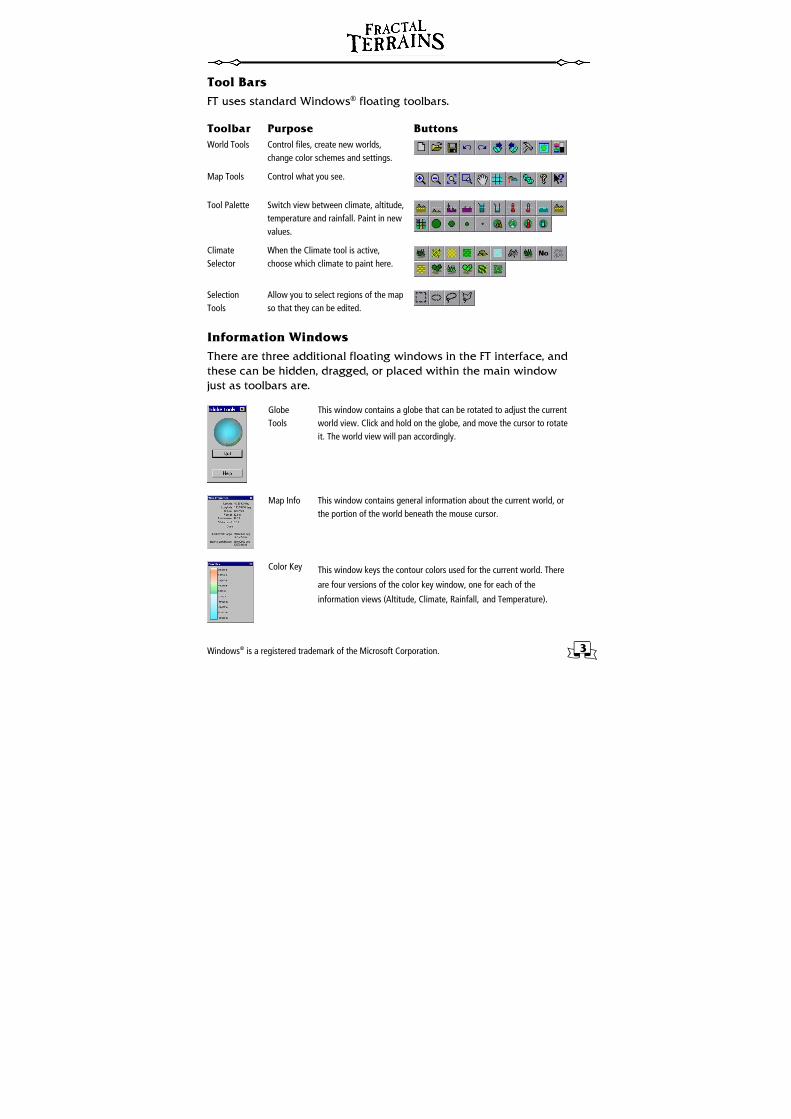
Tool Bars FT uses standard Windows® floating toolbars.
Toolbar Purpose Buttons World Tools Control files, create new worlds,
change color schemes and settings.
Map Tools Control what you see.
Tool Palette Switch view between climate, altitude, temperature and rainfall. Paint in new values.
Climate Selector
When the Climate tool is active, choose which climate to paint here.
Selection Tools
Allow you to select regions of the map so that they can be edited.
Information Windows There are three additional floating windows in the FT interface, and these can be hidden, dragged, or placed within the main window just as toolbars are.
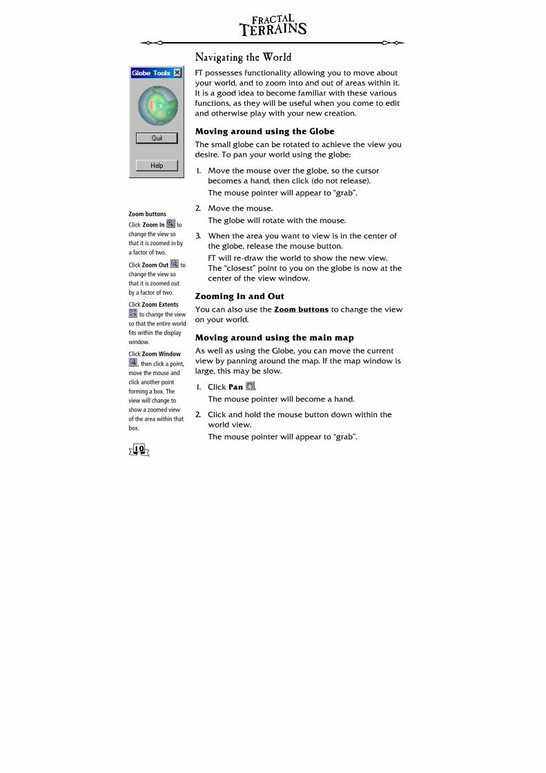
Globe Tools
This window contains a globe that can be rotated to adjust the current world view. Click and hold on the globe, and move the cursor to rotate it. The world view will pan accordingly.
Map Info This window contains general information about the current world, or the portion of the world beneath the mouse cursor.
Color Key This window keys the contour colors used for the current world. There
are four versions of the color key window, one for each of the
information views (Altitude, Climate, Rainfall, and Temperature).
Windows® is a registered trademark of the Microsoft Corporation.
4
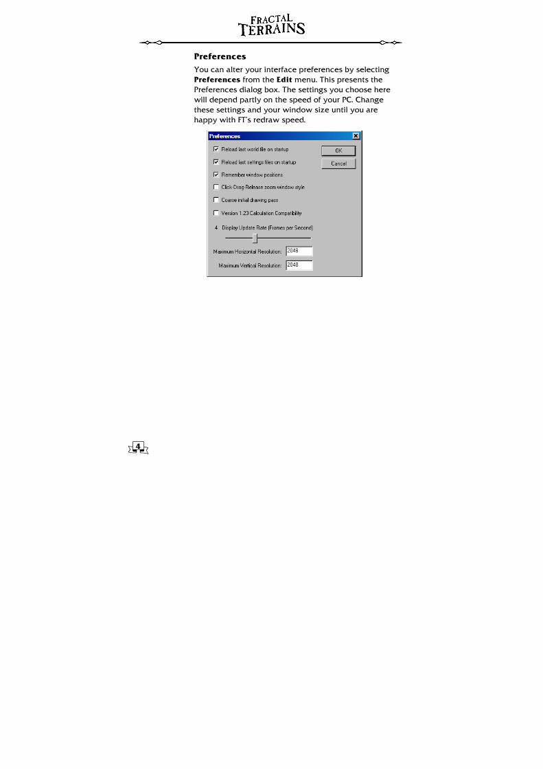
Preferences You can alter your interface preferences by selecting Preferences from the Edit menu. This presents the Preferences dialog box. The settings you choose here will depend partly on the speed of your PC. Change these settings and your window size until you are happy with FT’s redraw speed.
5
World Settings
You can also access this dialog to edit the current world by clicking on the World
Settings button.
Units
By default, this will be Miles. Click the Advanced button and select Metric Units if you would prefer to use meters, kilometers and degrees Celcius.
Synthetic World • A synthetic world
is one created by FT’s fractal functions.
• A binary world is one created from imported data.
• A flat world is a billiard ball, ready for you to edit yourself.
Your First World Double-click FT on your computer’s desktop. You will be presented with several windows that comprise FT’s main screen. We recommend that you do not run FT in a maximized window unless you have a very fast PC.
Starting a Random World
1. On the File menu click New.
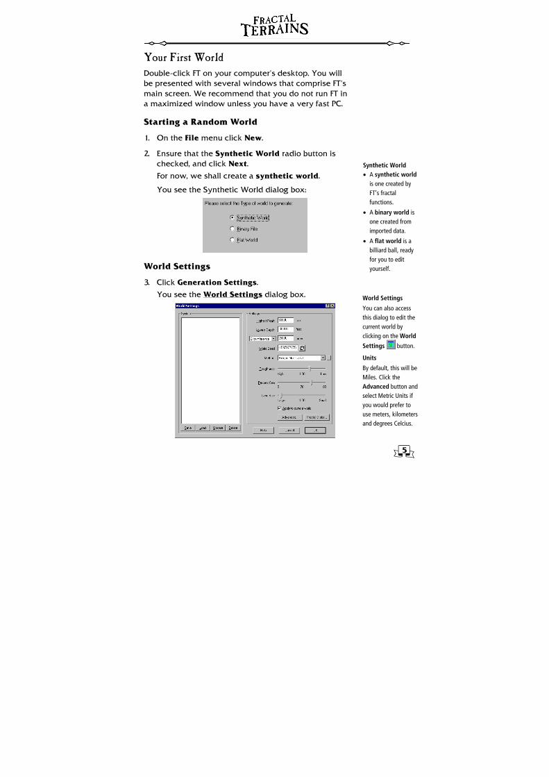
2. Ensure that the Synthetic World radio button is checked, and click Next.
For now, we shall create a synthetic world.
You see the Synthetic World dialog box:
World Settings
3. Click Generation Settings.
You see the World Settings dialog box.
6
Method
Ridged
Multifractal
Brownian Noise
Highest Peak and Lowest Depth sets the maximum and minimum altitudes for the world. Sometimes the generated world may exceed these values, but it usually keeps within the bounds.
The Circumference or Diameter (depending on the option selected from the drop-list) in the current units.
The World Seed is the world number to generate. It sets the random number seed for the internal generators. Click on to randomly allocate this value.
Method selects the way altitude will be computed. Two options are available: Ridged Multifractal and Brownian Noise. Ridged Multifractal is composed of many ridges at different scales. Brownian Noise is random noise at different scales, without structure.
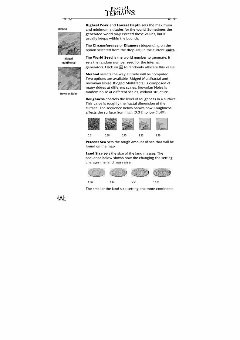
Roughness controls the level of roughness in a surface. This value is roughly the fractal dimension of the surface. The sequence below shows how Roughness affects the surface from high (0.01) to low (1.49):
0.01 0.38 0.75 1.13 1.49
Percent Sea sets the rough amount of sea that will be found on the map.
Land Size sets the size of the land masses. The sequence below shows how the changing the setting changes the land mass size:
1.00 2.14 5.50 10.00
The smaller the land size setting, the more continents
7
Advanced World Settings
These settings allow you to affect the way in which the world is calculated. You may also change climate coloration, the location of the northernmost pole, axial tilt, etc.
If Continental Shelves are selected, the value on this line is the depth at which the shelves will be generated.
The North Pole Position group controls the location of the north pole. The change will not be applied to any terrain editing.
Axis Tilt affects the temperature distribution of the world.
The Temperature Calcs group controls the settings for the temperature model.
Rainfall, base controls the average rainfall, and Random, the variation.
(or islands) you will get. A value of around 1.6 usually provides good results.
4. The three settings you want to concentrate on are Roughness, Percent Sea, and Land Size. Try the following values:
• Roughness: 0.75
• Percent Sea: 50
• Land Size: 2.44
5. Keep the other values the same.
6. Click Advanced.
You see the Advanced World Settings dialog box.
7. Click the Small Editing Setup radio button.
Changing this setting will affect the resolution used to depict your world, and the amount of memory FT will need. For your first world, we will use the Small setup to save time while you explore FT’s functions.
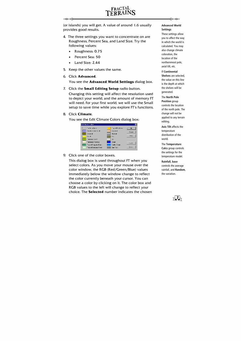
8. Click Climate.
You see the Edit Climate Colors dialog box:
9. Click one of the color boxes.
This dialog box is used throughout FT when you select colors. As you move your mouse over the color window, the RGB (Red/Green/Blue) values immediately below the window change to reflect the color currently beneath your cursor. You can choose a color by clicking on it. The color box and RGB values to the left will change to reflect your choice. The Selected number indicates the chosen
8
Color Settings
If the Blended check boxes are set, FT will draw the contour colors so that the transition between one contour and the next flows smoothly. While this produces a more realistic look, it can slow down world redraws.
If the Shaded check box is set, FT will calculate and draw shaded highlights to raised terrain features. As with blending, shading can slow down redraw times, but will produce a more realistic effect.
The Sea Shading check box is used to tell FT whether to draw similar shading for sea depth contours. This check box will not be available if the Shaded check box is not checked.
color’s value within the standard CC2-Pro. You can also affect the color schemes for Temperature and Rainfall in this way.
10. Unless you wish to change the color used for the climate type you have chosen, press Cancel to return to the Edit Climate Color dialog box.
11. Press OK to return to the Advanced World Settings dialog box, and again to return to the World Settings dialog, and once more to return to the Synthetic World dialog.
Color Settings
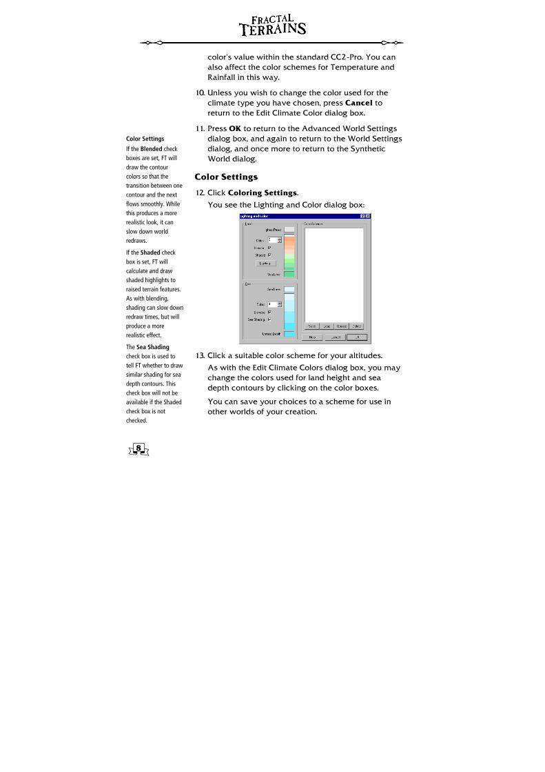
12. Click Coloring Settings.
You see the Lighting and Color dialog box:
13. Click a suitable color scheme for your altitudes.
As with the Edit Climate Colors dialog box, you may change the colors used for land height and sea depth contours by clicking on the color boxes.
You can save your choices to a scheme for use in other worlds of your creation.
9
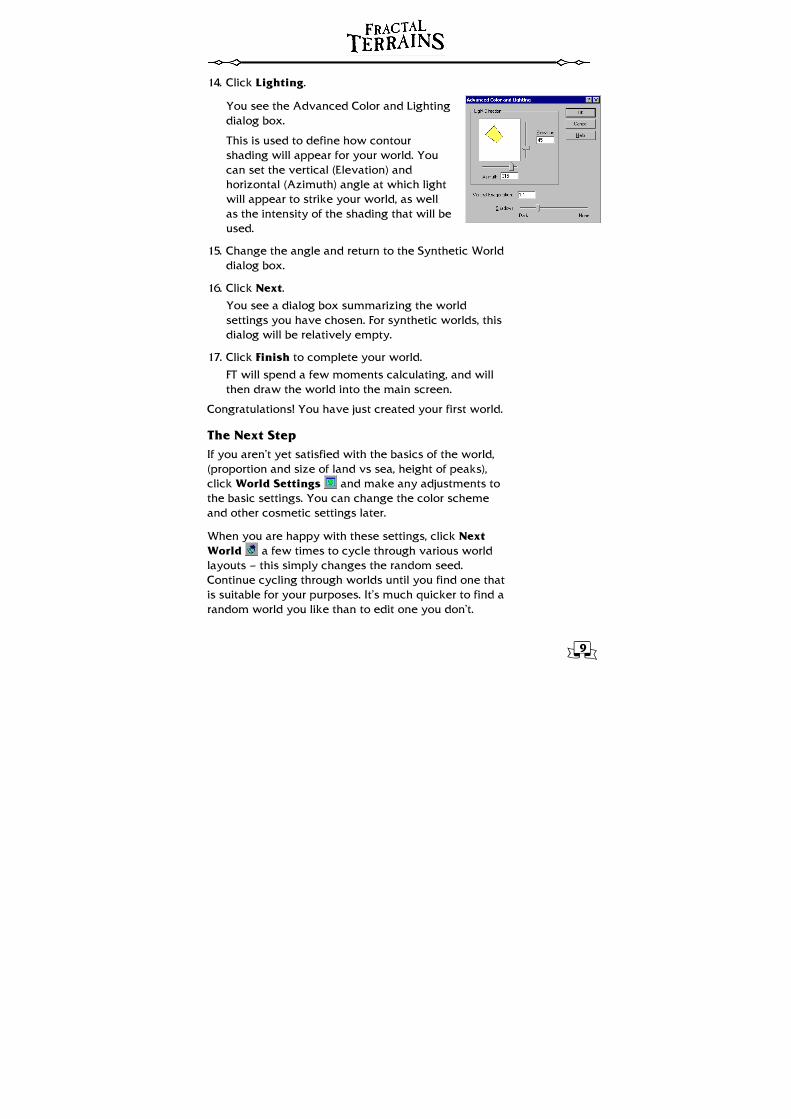
14. Click Lighting.
You see the Advanced Color and Lighting dialog box.
This is used to define how contour shading will appear for your world. You can set the vertical (Elevation) and horizontal (Azimuth) angle at which light will appear to strike your world, as well as the intensity of the shading that will be used.
15. Change the angle and return to the Synthetic World dialog box.
16. Click Next.
You see a dialog box summarizing the world settings you have chosen. For synthetic worlds, this dialog will be relatively empty.
17. Click Finish to complete your world.
FT will spend a few moments calculating, and will then draw the world into the main screen.
Congratulations! You have just created your first world.
The Next Step If you aren’t yet satisfied with the basics of the world, (proportion and size of land vs sea, height of peaks), click World Settings and make any adjustments to the basic settings. You can change the color scheme and other cosmetic settings later.
When you are happy with these settings, click Next World a few times to cycle through various world layouts — this simply changes the random seed. Continue cycling through worlds until you find one that is suitable for your purposes. It’s much quicker to find a random world you like than to edit one you don’t.
10
Zoom buttons
Click Zoom In to change the view so that it is zoomed in by a factor of two.
Click Zoom Out to change the view so that it is zoomed out by a factor of two.
Click Zoom Extents
to change the view so that the entire world fits within the display window.
Click Zoom Window
, then click a point, move the mouse and click another point forming a box. The view will change to show a zoomed view of the area within that box.
Navigating the World FT possesses functionality allowing you to move about your world, and to zoom into and out of areas within it. It is a good idea to become familiar with these various functions, as they will be useful when you come to edit and otherwise play with your new creation.
Moving around using the Globe The small globe can be rotated to achieve the view you desire. To pan your world using the globe:
1. Move the mouse over the globe, so the cursor becomes a hand, then click (do not release).
The mouse pointer will appear to “grab”.
2. Move the mouse.
The globe will rotate with the mouse.
3. When the area you want to view is in the center of the globe, release the mouse button.
FT will re-draw the world to show the new view. The “closest” point to you on the globe is now at the center of the view window.
Zooming In and Out You can also use the Zoom buttons to change the view on your world.
Moving around using the main map As well as using the Globe, you can move the current view by panning around the map. If the map window is large, this may be slow.
1. Click Pan .
The mouse pointer will become a hand.
2. Click and hold the mouse button down within the world view.
The mouse pointer will appear to “grab”.

11
Map Projection Dialog Box
The Map Projection dialog has three basic sets of parameters:
Projection Center, represented by the values Lat (latitude) and Lon (longitude), defines the central point for the projection display;
View Offset (represented by XOfs and YOfs) defines the offset from the projection center to the center of the area of interest. View Offsets can be used to center a view to a particular latitude and longitude co-ordinate.
Scale, expressed as a zoom ratio (e.g., a Scale of 1 will display the entire world, 0.5 will zoom in by a factor of ×2, 4 will zoom out by a factor of ×1/4, and so on).
3. Move the mouse through the desired pan distance and direction, then release the mouse button.
FT moves the map within the view window to show you the new view area.
4. Alternatively you can hold down SHIFT while using the pan tool. This rotates the world, rather than simply moving the map area in the view window. This is easier to see than explain, so Zoom Extents then try SHIFT-panning.
Map Projections Displaying a 3D globe on a flat surface poses a problem. Over the years, several different methods of achieving this have been devised. Such methods produce flat-map views, or projections, of the globe. FT can display your world using many projection methods.
1. Click Change Projection .
You see the Map Projection dialog box.
2. Click one of the listed map projections.
The preview of the world will change to reflect the selected projection. We recommend the Equirectangular projection as the best all-round option.
Named Views You can create named views for your world. When a named view is created, map projection, scale, and position are stored within it. Named views can be used for world navigation and to export sections of worlds.
12
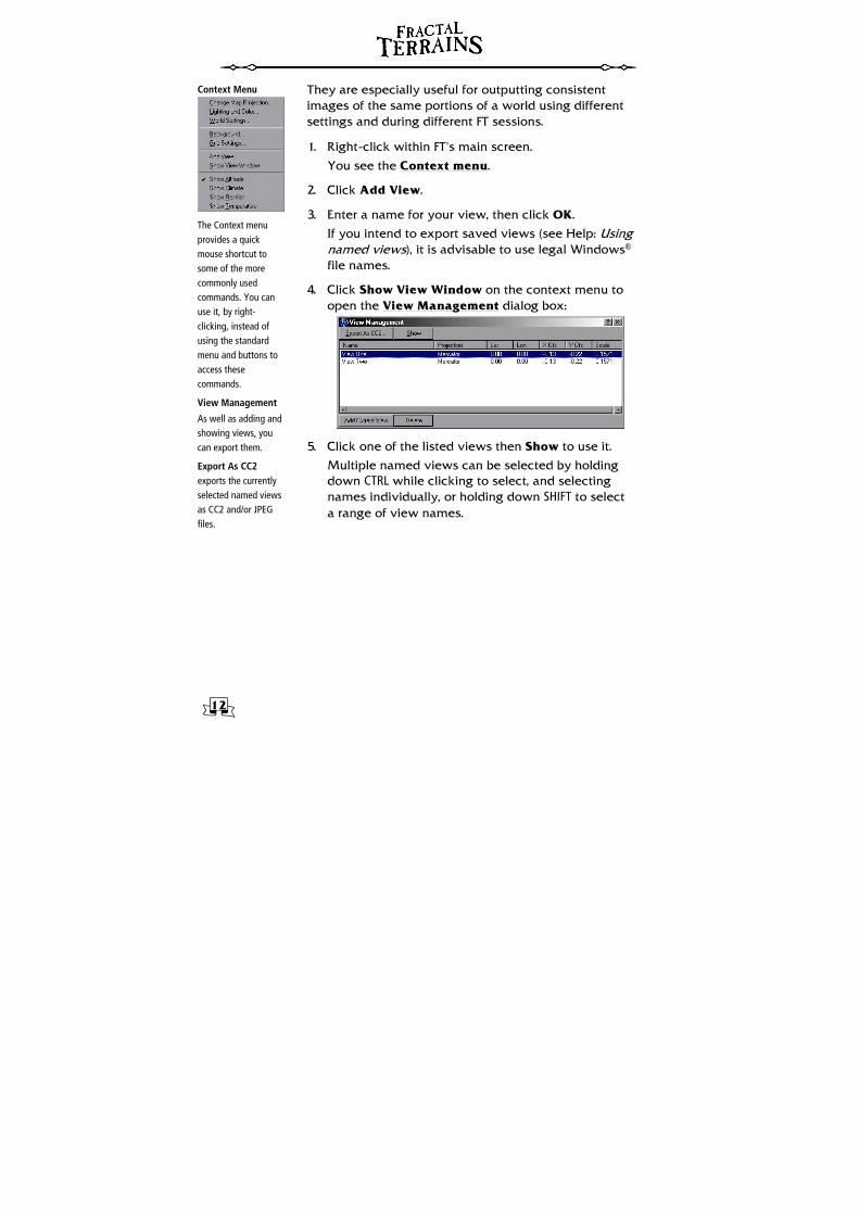
Context Menu
The Context menu provides a quick mouse shortcut to some of the more commonly used commands. You can use it, by right-clicking, instead of using the standard menu and buttons to access these commands.
View Management
As well as adding and showing views, you can export them.
Export As CC2 exports the currently selected named views as CC2 and/or JPEG files.
They are especially useful for outputting consistent images of the same portions of a world using different settings and during different FT sessions.
1. Right-click within FT’s main screen.
You see the Context menu.
2. Click Add View.
3. Enter a name for your view, then click OK.
If you intend to export saved views (see Help: Using named views), it is advisable to use legal Windows® file names.
4. Click Show View Window on the context menu to open the View Management dialog box:
5. Click one of the listed views then Show to use it.
Multiple named views can be selected by holding down CTRL while clicking to select, and selecting names individually, or holding down SHIFT to select a range of view names.
13
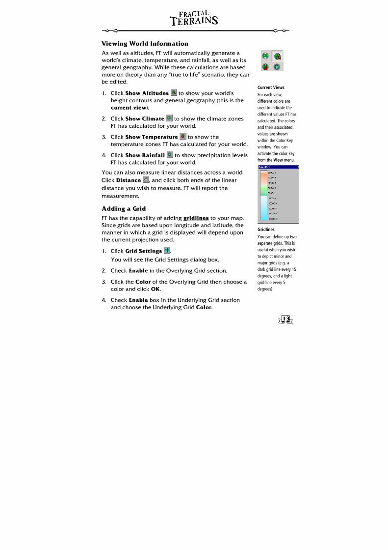
Current Views
For each view, different colors are used to indicate the different values FT has calculated. The colors and their associated values are shown within the Color Key window. You can activate the color key from the View menu.
Gridlines
You can define up two separate grids. This is useful when you wish to depict minor and major grids (e.g. a dark grid line every 15 degrees, and a light grid line every 5 degrees).
Viewing World Information As well as altitudes, FT will automatically generate a world’s climate, temperature, and rainfall, as well as its general geography. While these calculations are based more on theory than any “true to life” scenario, they can be edited.
1. Click Show Altitudes to show your world’s height contours and general geography (this is the current view).
2. Click Show Climate to show the climate zones FT has calculated for your world.
3. Click Show Temperature to show the temperature zones FT has calculated for your world.
4. Click Show Rainfall to show precipitation levels FT has calculated for your world.
You can also measure linear distances across a world. Click Distance , and click both ends of the linear distance you wish to measure. FT will report the measurement.
Adding a Grid FT has the capability of adding gridlines to your map. Since grids are based upon longitude and latitude, the manner in which a grid is displayed will depend upon the current projection used.
1. Click Grid Settings .
You will see the Grid Settings dialog box.
2. Check Enable in the Overlying Grid section.
3. Click the Color of the Overlying Grid then choose a color and click OK.
4. Check Enable box in the Underlying Grid section and choose the Underlying Grid Color.
14
5. Change the Longitude and Latitude Spacing values for each grid section. It is normal to set the Overlying grid as a multiple of the Underlying grid. Try 30 for Overlying and 10 for Underlying.
6. Move the Subdivision Level slider bar so that the setting reads 2 Divisions. Click OK.
The Map Info window This window contains general information about the current world, or the portion of the world beneath the mouse cursor. It’s good to give you an idea of maximum and minimum values on the world, as well as for choosing suitable areas of land to export.
Distance Measurement You can also measure linear distances across a world. Click Distance and then click both ends of the linear distance you wish to measure. FT will report the measurement.
15
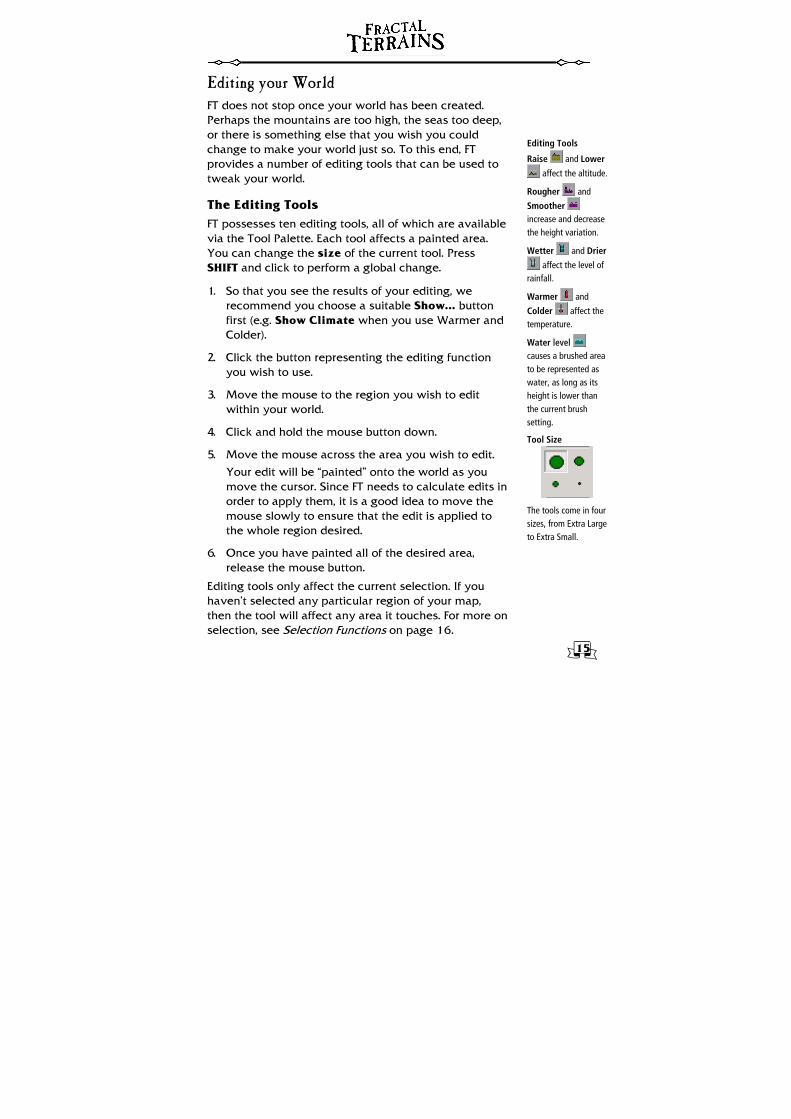
Editing Tools
Raise and Lower
affect the altitude.
Rougher and
Smoother increase and decrease the height variation.
Wetter and Drier
affect the level of rainfall.
Warmer and
Colder affect the temperature.
Water level causes a brushed area to be represented as water, as long as its height is lower than the current brush setting.
Tool Size
The tools come in four sizes, from Extra Large to Extra Small.
Editing your World FT does not stop once your world has been created. Perhaps the mountains are too high, the seas too deep, or there is something else that you wish you could change to make your world just so. To this end, FT provides a number of editing tools that can be used to tweak your world.
The Editing Tools FT possesses ten editing tools, all of which are available via the Tool Palette. Each tool affects a painted area. You can change the size of the current tool. Press SHIFT and click to perform a global change.
1. So that you see the results of your editing, we recommend you choose a suitable Show... button first (e.g. Show Climate when you use Warmer and Colder).
2. Click the button representing the editing function you wish to use.
3. Move the mouse to the region you wish to edit within your world.
4. Click and hold the mouse button down.
5. Move the mouse across the area you wish to edit.
Your edit will be “painted” onto the world as you move the cursor. Since FT needs to calculate edits in order to apply them, it is a good idea to move the mouse slowly to ensure that the edit is applied to the whole region desired.
6. Once you have painted all of the desired area, release the mouse button.
Editing tools only affect the current selection. If you haven’t selected any particular region of your map, then the tool will affect any area it touches. For more on selection, see Selection Functions on page 16.
16
Set Values
Note that the editing tools may have no discernable effect when using low tool settings values at high zoom levels.
Selection by Shape
Select Rectangle
Select Ellipse Click to place the first corner, move the mouse, then click again to place the opposite corner.
Select Freehand
to manually draw a selection mask. Click to start the selection, draw the required selection by moving the mouse, click to complete.
Select Polygon
Click to start the selection, then click to place further points as desired. To complete the selection, either triple-click (effectively clicking once to place the final point, then double-clicking in the same location to complete), or press ENTER.
Changing the Editing Tools
You can set the extent to which edits are applied by clicking Tool Options . The Tool Settings dialog box will appear, in which you can specifically set values used by the editing functions.
Climate Painting
Paint Climate , is used to change the climate settings for an area painted. To use this tool, you must first select the type of climate you wish to paint from the Climate Selector toolbar. Fifteen climate types are available.
Selection Functions FT provides a number of selection tools that can be used to mask portions of a world. When a selection mask is applied, all edits will only affect currently selected portions of a world. Global edits will be applied to all areas within the selection, and areas outside the selection will remain untouched.
Basic Selection Functions Three basic functions are accessed from the Select menu. These are:
• All selects the entire world. • Deselect deselects all current selections. • Inverse inverts the current selection, so that
everything currently selected is now de-selected, and everything that was outside the current selection becomes selected.
Selection Tools Four tools are provided which allow selection by shape. These tools can be found on the Selection Tools toolbar. Enable Selection Tools from the View menu to display this toolbar.
17
Range Selection
Altitude Range selects by altitude, in feet (or meters).
Temperature Range selects by temperature, in °F (or °C).
Rainfall Range selects by rainfall, in inches per year (or cm).
Selecting by Climate Range always replaces the current selection. This opens a dialog box which lists all of the climates FT recognizes. Check boxes to the left of the listed climates to include them in the selection.
These selection tools can also be used to add to or subtract from the current selection. Holding down SHIFT when completing the selection will add the area to the current selection, and holding down CTRL will remove the area drawn from the current selection.
Range Selection Functions The Select menu provides four range selection functions that are used to select portions of the world that conform to given parameters. With the exception of the Climate Range function, these tools prompt for the range required via a dialog box.
Selection Mask Modification The current selection mask can be further modified.
Binarize will “harden” the selection, so that each pixel is either fully selected or fully deselected.
Feather will “soften” the selection mask, blurring it around the edges. You will be prompted to enter the amount by which the selection is to be smoothed. Feathered selections can have partially selected pixels.
Modify >> Expand will increase the size of the current selection by one pixel in all directions.
Modify >> Contract will decrease the size of the current selection by one pixel in all directions.
Selection Mask Files You can save selections for use in the future as selection mask files.
Save Selection will save the current selection as a bitmap file.
Load Selection will prompt for the selection mask file to use, and will then apply that to the current world.
18
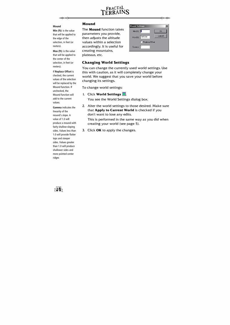
Mound
Min (ft): is the value that will be applied to the edge of the selection, in feet (or meters).
Max (ft): is the value that will be applied to the center of the selection, in feet (or meters).
If Replace Offset is checked, the current values of the selection will be replaced by the Mound function. If unchecked, the Mound function will add to the current values.
Gamma indicates the linearity of the mound’s slope. A value of 1.0 will produce a mound with fairly shallow-sloping sides. Values less than 1.0 will provide flatter tops and steeper sides. Values greater than 1.0 will produce shallower sides and more pointed center ridges
Mound The Mound function takes parameters you provide, then adjusts the altitude values within a selection accordingly. It is useful for creating mountains, plateaus, etc.
Changing World Settings You can change the currently used world settings. Use this with caution, as it will completely change your world. We suggest that you save your world before changing its settings.
To change world settings:
1. Click World Settings .
You see the World Settings dialog box.
2. Alter the world settings to those desired. Make sure that Apply to Current World is checked if you don’t want to lose any edits.
This is performed in the same way as you did when creating your world (see page 5).
3. Click OK to apply the changes.
19
Synthetic World dialog box
Flat worlds use the same underlying setup as do synthetic worlds.
Raised the Height
Because of the way the raise and lower tools work, it’s better to start with a raised surface and use the lower tools to make seas than vice versa.
Flat Worlds If you want to manually draw land patterns, rather than allowing FT to randomly generate them for you, you can create a new world that possesses a flat, featureless terrain.
Using a flat world as a starting point, you can then use the editing tools to paint terrain features as you wish.
To start a new flat world:
1. On the File menu, click New.
You see the Select World Type dialog box:.
2. Check the Flat World radio button then click Next.
You see the Synthetic World dialog box.
3. Click Generation Settings button, and set desired options, particularly the Circumference and expected maximum heights and depths.
4. Click Coloring Settings and choose your contour color scheme.
Steps 3 and 4 are performed in exactly the same way as for synthetic worlds. See the Your First World tutorial.
5. From the Synthetic World dialog, click Next.
FT shows a summary of the world settings.
6. Click Finish to generate the world.
FT displays the flat world. The altitude is 0 feet (sea level) all over, and therefore normally shown blue.
7. On the Tools menu, click Global Set >> Altitude, type 100 and press OK.
FT raises the height all over the globe, and it’s therefore normally plain green.
The world may now be edited as you see fit using FT’s editing tools.

20
Import binary data
Note that the binary file used must be present for as long as you intend to use the world file. FT does not import the binary data into its own format, but rather uses the binary file for reference. Moving or deleting the binary file after saving a world created with it will result in the world file being unusable. This can be avoided by using the Burn In To Surface function, which is further detailed below.
Required File
In most cases it is better to copy data files onto your hard drive before using them to make maps, as this improves the speed of FT.
Creating Worlds from Real World Data As well as being able to create worlds from scratch, FT has the ability to import binary data files that define sections of terrain. You will find examples of such files, from the GTOPO30 real-world data sets, that you can import into FT to produce maps based on Earth.
Creating a World
1. Click New.
You see the Select World Type dialog box.
2. Pick the Binary File radio button, then click Next.
3. Click Choose Elevation File.
You see the Binary Data dialog box:
4. Click to select the required file from a dialog box. Select the file ETOPO5.bin in the Terrain Data folder.
FT automatically finds the header file for the data and asks whether to use it. Click Yes. The header file sets the remaining values in the dialog box.
5. Press OK to return to the Binary Data wizard.
6. Select the Synthetic Coloring radio button.
21
FT’s native Format
As a side effect, the Burn To Surface function removes the contribution of the fractal basis function, resulting in a smoother map. This makes the function useful for worlds that do not use binary files.
Burned files are much bigger than raw, unedited FT files.
This will use the same color settings FT uses by default when creating synthetic worlds.
7. Click Next.
FT shows a summary of the map to generate.
8. Click Finish to start generation.
FT calculates and display the new map in the main window.
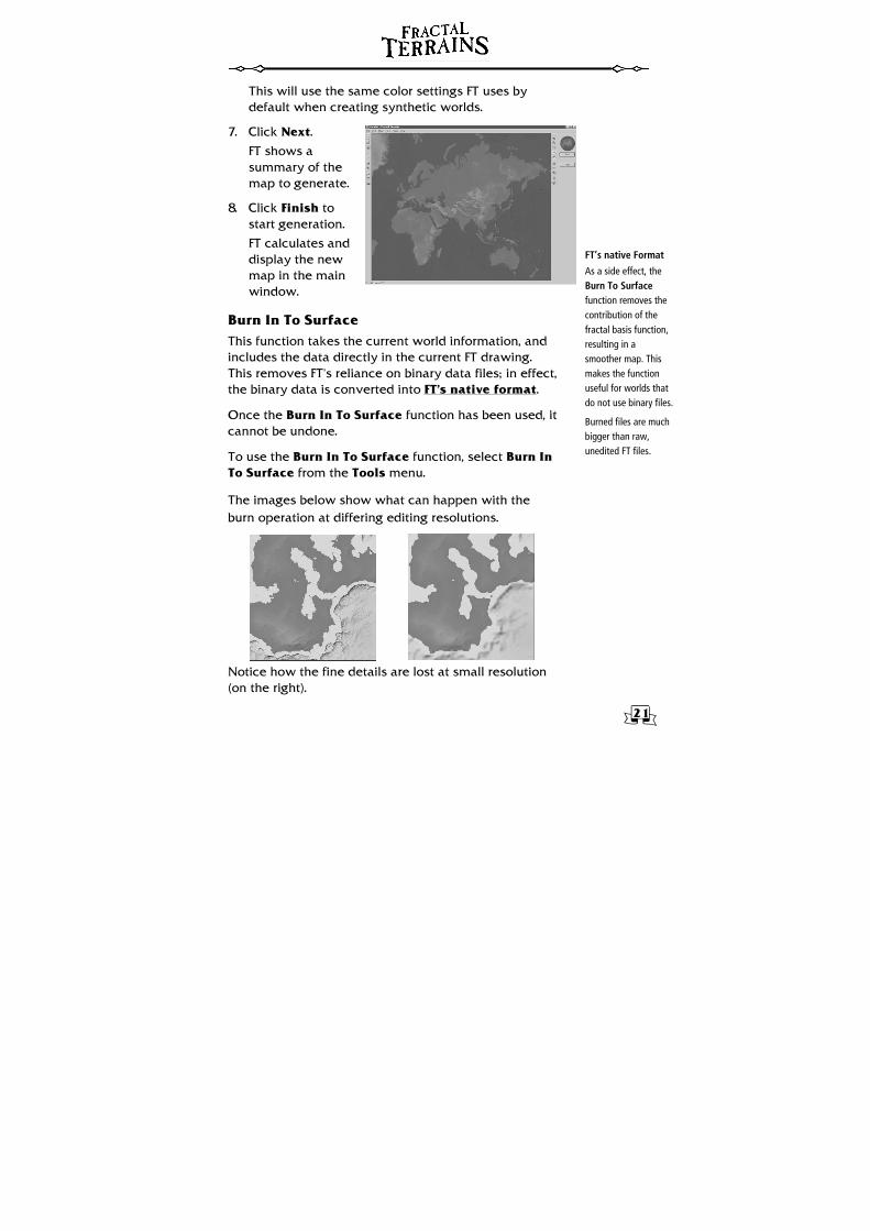
Burn In To Surface This function takes the current world information, and includes the data directly in the current FT drawing. This removes FT’s reliance on binary data files; in effect, the binary data is converted into FT’s native format.
Once the Burn In To Surface function has been used, it cannot be undone.
To use the Burn In To Surface function, select Burn In To Surface from the Tools menu.
The images below show what can happen with the burn operation at differing editing resolutions.
Notice how the fine details are lost at small resolution (on the right).
22
Export
FT’s native file format is FTW. You should always save your world in FT’s own format, especially if you intend to use FT to further edit and refine it. FT also supports.
• Bitmap image format (BMP)
• JPEG image format (JPG)
• Wilbur format (MDR)
• Special MDR (MDR)
Exporting and Importing Once you have edited your world so that everything matches your desires, you may now wish to export it to an image file, a series of image files, or even to a Virtual Reality Modeling Language model.
File Formats The BMP, JPEG, and Wilbur (MDR) formats all save the current view (not the whole map) as either a color map or as a height field readable by Wilbur. These formats have limits on the size of an image that can be saved. The Special MDR format, on the other hand, has no limit on the size of the output image and always outputs its information using a simple Equirectangular projection. This format is very useful when exporting a high-resolution image from FT to use as a binary image within FT or as an input file within Wilbur.
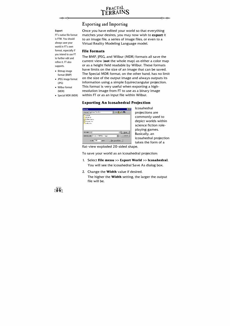
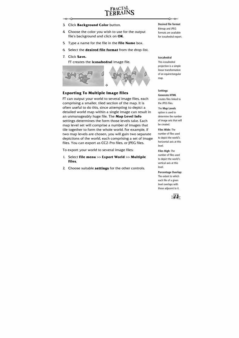
Exporting An Icosahedral Projection Icosahedral projections are commonly used to depict worlds within science fiction role-playing games. Basically, an icosahedral projection takes the form of a
flat-view exploded 20-sided shape.
To save your world as an icosahedral projection:
1. Select File menu >> Export World >> Icosahedral.
You will see the icosahedral Save As dialog box.
2. Change the Width value if desired.
The higher the Width setting, the larger the output file will be.
23
Isocahedral
This icosahedral projection is a simple linear transformation of an equirectangular map.
Desired file format
Bitmap and JPEG formats are available for icosahedral export.
Settings
Generate HTML creates files linked to the JPEG files.
The Map Levels option is used to determine the number of image sets that will be created.
Files Wide: The number of files used to depict the world’s horizontal axis at this level.
Files High: The number of files used to depict the world’s vertical axis at this level.
Percentage Overlap: The extent to which each file of a given level overlaps with those adjacent to it.
3. Click Background Color button.
4. Choose the color you wish to use for the output file’s background and click on OK.
5. Type a name for the file in the File Name box.
6. Select the desired file format from the drop-list.
7. Click Save.
FT creates the icosahedral image file.
Exporting To Multiple Image Files FT can output your world to several image files, each comprising a smaller, tiled section of the map. It is often useful to do this, since attempting to depict a detailed world map within a single image can result in an unmanageably huge file. The Map Level Info settings determines the form those levels take. Each map level set will comprise a number of images that tile together to form the whole world. For example, if two map levels are chosen, you will gain two separate depictions of the world, each comprising a set of image files. You can export as CC2-Pro files, or JPEG files.
To export your world to several image files:
1. Select File menu >> Export World >> Multiple Files.
2. Choose suitable settings for the other controls.
24
Settings (cont)
Image Resolution: The pixel resolution of the resultant images. The higher this value is, the larger the resultant files will be.
Per-Level CC2: When Generate CC2 Files is enabled, this option allows you to choose different CC2 export settings for each level of zoom. Click the blank button next to each level to choose its CC2 export setting.
Export Parameters
Size: The size of each frame in pixels.
# Frames: The number of images that will be created. If used for animation, the higher this value is the smoother the resultant animation will be.
Latitude: The degree of latitude that will form the center point of the rotational view.
Appear to be Shaded: Check this box if you wish the world to appear shaded.
3. To choose a location for the output files, click the directory selection button .
4. Click on OK to start the export.
FT will generate the files to the specifications you have set, and an overview file depicting the entire world. This process may take some time, depending on the number and nature of levels you have chosen.
The files will have a filename consisting of a letter and a number. The letter refers to the map level (the overview map will be “A”, level one will be “B”, and so on). The number refers to the row and column of the map’s tile.
Exporting A Spin View A spin view is a series of image files that depict the globe in a period of rotation. These files may be then combined in a third party application to form a rotating globe animation.
1. Select File menu >> Export World >> Spin View.
You will see the Spin View Export dialog box:
2. Set up the export parameters desired.
3. Type a name for the file in the File Name box.
4. Select the desired file format from the drop-list.
Bitmap and JPEG formats are available for spin view export.
5. Click Save.
FT creates the spin view image files. Each file will consist of the selected filename, plus a numerical suffix indicating where in the rotational sequence the file occurs.
25
Export views
This command saves the current FT view to CC2-Pro. Thus, to produce a CC2-Pro map covering a small area of your world, just zoom into the area required. To ensure that the same view can be exported during different FT sessions, use the Named View features available from the View menu.
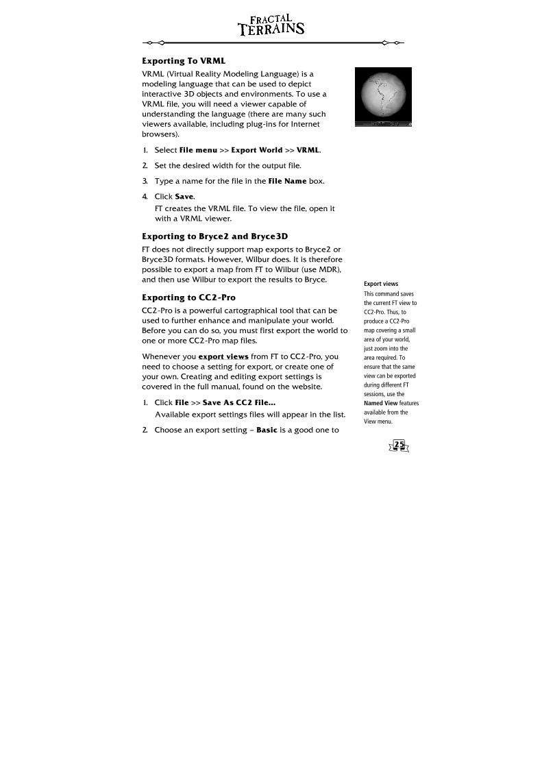
Exporting To VRML VRML (Virtual Reality Modeling Language) is a modeling language that can be used to depict interactive 3D objects and environments. To use a VRML file, you will need a viewer capable of understanding the language (there are many such viewers available, including plug-ins for Internet browsers).
1. Select File menu >> Export World >> VRML.
2. Set the desired width for the output file.
3. Type a name for the file in the File Name box.
4. Click Save.
FT creates the VRML file. To view the file, open it with a VRML viewer.
Exporting to Bryce2 and Bryce3D FT does not directly support map exports to Bryce2 or Bryce3D formats. However, Wilbur does. It is therefore possible to export a map from FT to Wilbur (use MDR), and then use Wilbur to export the results to Bryce.
Exporting to CC2-Pro CC2-Pro is a powerful cartographical tool that can be used to further enhance and manipulate your world. Before you can do so, you must first export the world to one or more CC2-Pro map files.
Whenever you export views from FT to CC2-Pro, you need to choose a setting for export, or create one of your own. Creating and editing export settings is covered in the full manual, found on the website.
1. Click File >> Save As CC2 File...
Available export settings files will appear in the list.
2. Choose an export setting — Basic is a good one to
26
Image File
If Microsoft Internet Explorer® 4.0 or higher is installed on your system you may select BMP, GIF, JPEG, or PNG files. If it is not, you are limited to BMP files alone.
start with.
3. Click Export World.
Exporting To Multiple CC2 Maps Just as you can export worlds to multiple tiled image files, you can export them to multiple CC2 maps (see page 23). You can export all maps with the same setting, or check the Per Level CC2 options and use a separate export setting for each map level.
Importing CC2 maps with Wilbur FT is not really configured for importing CC2-Pro maps, but it is possible with a little work. See the full manual for details.
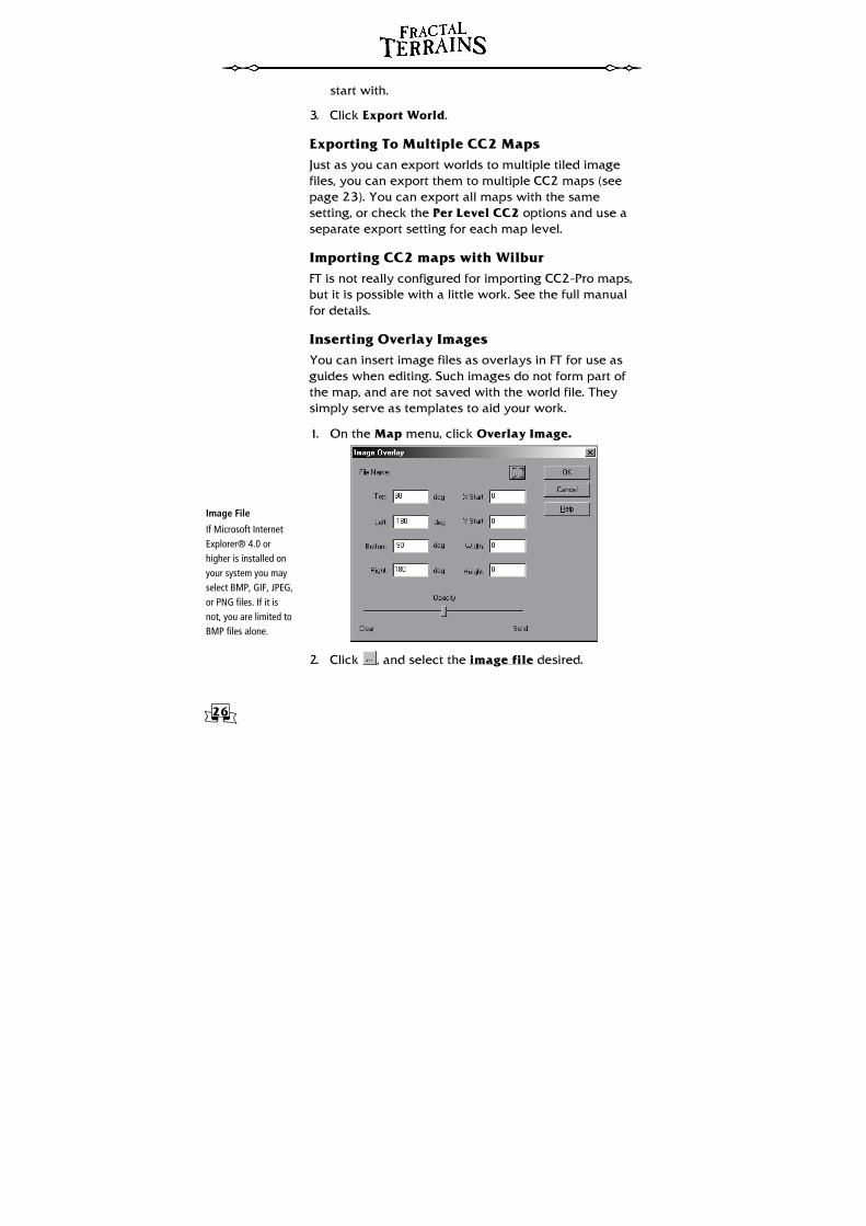
Inserting Overlay Images You can insert image files as overlays in FT for use as guides when editing. Such images do not form part of the map, and are not saved with the world file. They simply serve as templates to aid your work.
1. On the Map menu, click Overlay Image.
2. Click , and select the image file desired.
27
Parameters
Top, Left, Bottom, and Right are the edges of the area that will be occupied by the image. Top and Bottom are latitudes, Left and Right are longitudes.
X Start, Y Start, Width, and Height indicate the area of the image to be used in the overlay, as pixel references.
The Opacity slider controls the transparency of the image, as it will appear in the main window. Moving the slider towards the Clear end of the slider makes the image more transparent, towards the Solid end less so.
3. Enter parameters in the Image Overlay dialog box according to the resolution of the image file you selected, and your requirements.
4. Press OK.
5. To remove the overlay, open the Map Overlay dialog again and click Cancel instead of OK. It may also be removed by re-loading the world once your edits have been saved.
28
Advanced Features and Further Reading A complete tutorial on world creation is included with the full manual. The full manual also covers the following topics.
• CC2-Pro Export settings • Creating color contour settings • Importing maps to CC2-Pro via Wilbur • Controlling lighting • Map projections • How FT’s fractal functions work • How climate, rainfall and temperature are
determined • Advanced World Settings
Bibliography Some books that also can help in the understanding of map projections are:
An Album of Map Projections (Snyder and Voxland; US Geologic Survey Professional Paper 1453)
Map Projections — A Reference Manual (Bugayevskiy and Snyder; ISBN 07484 0304 3)
Flattening the Earth (Snyder; ISBN 0-226-76747-7)
The Album is out of print, but the others are readily available.