fr series power amplifiers owner's manual€¦ · · 2016-07-20keep the owner’s manual...
TRANSCRIPT
O W N E R ’ S M A N U A L
TWO CHANNEL POWER AMPLIFIERSFR•800, FR•1400, and FR•2500
FR Series

� FR SERIES AMPLIFIERS
FR S
ER
IES A
MPLIF
IER
S
1. Readtheseinstructions.
2. Keeptheseinstructions.
3. Heedallwarnings.
4. Followallinstructions.
5. Donotusethisapparatusnearwater.
6. Cleanonlywithdrycloth.
7. Donotblockanyventilationopenings.Installinaccordancewiththemanufacturer’sinstructions.
8. Donotinstallnearanyheatsourcessuchasradiators,heatregisters,stoves,orotherapparatus(includingamplifiers)thatproduceheat.
9. Donotdefeatthesafetypurposeofthepolarizedorgrounding-typeplug.Apolarizedplughastwobladeswithonewiderthantheother.Agrounding-typeplughastwobladesandathirdgroundingprong.Thewidebladeorthethirdprongareprovidedforyoursafety.Iftheprovidedplugdoesnotfitintoyouroutlet,consultanelectricianforreplacementoftheobsoleteoutlet.
10.Protectthepowercordfrombeingwalkedonorpinchedparticularlyatplugs,conveniencereceptacles,andthepointwheretheyexitfromtheapparatus.
11.Onlyuseattachments/accessoriesspecifiedbythemanufacturer.
12.Useonlywithacart,stand,tripod,bracket,ortablespecifiedbythemanufacturer,orsoldwiththeapparatus.Whenacartisused,usecautionwhenmovingthecart/apparatuscombinationtoavoidinjuryfromtip-over.
13.Unplugthisapparatusduringlightningstormsorwhenunusedforlongperiodsoftime.
14.Referallservicingtoqualifiedservicepersonnel.Servicingisrequiredwhentheapparatushasbeendamagedinanyway,suchaspower-supplycordorplugisdamaged,liquidhasbeenspilledorobjectshavefallenintotheapparatus,theapparatushasbeenexposedtorainormoisture,doesnotoperatenormally,orhasbeendropped.
15.Thisapparatusshallnotbeexposedtodrippingorsplashing,andnoobjectfilledwithliquids,suchasvasesorbeerglasses,shallbeplacedontheapparatus.
16.ThisapparatushasbeendesignedwithClass-Iconstructionandmustbeconnectedtoamainssocketoutletwithaprotectiveearthingcon-nection(thethirdgroundingprong).
17.Thisapparatushasbeenequippedwithanall-pole,rocker-styleACmainspowerswitch.Thisswitchislocatedonthefrontpanelandshouldremainreadilyaccessibletotheuser.
18.ThisapparatusdoesnotexceedtheClassA/ClassB(whicheverisapplicable)limitsforradionoiseemissionsfromdigitalapparatusassetoutintheradiointerferenceregulationsoftheCanadianDepartmentofCommunications.
ATTENTION—Le présent appareil numérique n’émet pas de bruits radioélectriques dépassant las limites applicables aux appareils numériques de class A/de class B (selon le cas) prescrites dans le réglement sur le brouillage radioélectrique édicté par les ministere des communications du Canada.
19.Exposuretoextremelyhighnoiselevelsmaycausepermanenthearingloss.Individualsvaryconsiderablyinsusceptibilitytonoise-inducedhearingloss,butnearlyeveryonewilllosesomehearingifexposedtosufficientlyintensenoiseforaperiodoftime.TheU.S.Government’sOccupationalSafetyandHealthAdministration(OSHA)hasspecifiedthepermissiblenoiselevelexposuresshowninthefollowingchart.
AccordingtoOSHA,anyexposureinexcessofthesepermissiblelimitscouldresultinsomehearingloss.Toensureagainstpotentiallydanger-ousexposuretohighsoundpressurelevels,itisrecommendedthatallpersonsexposedtoequipmentcapableofproducinghighsoundpres-surelevelsusehearingprotectorswhiletheequipmentisinoperation.Earplugsorprotectorsintheearcanalsorovertheearsmustbewornwhenoperatingtheequipmentinordertopreventpermanenthearinglossifexposureisinexcessofthelimitssetforthhere.
Important Safety Instructions
Duration Per Day Sound Level dBA, Typical In Hours Slow Response Example
8 90 Duoinsmallclub
6 92
4 95 SubwayTrain
3 97
2 100 Veryloudclassicalmusic
1.5 102
1 105 DavescreamingatSteveaboutdeadlines
0.5 110
0.25orless 115 Loudestpartsatarockconcert
WARNING—Toreducetheriskoffireorelectricshock,donotexposethisapparatus
torainormoisture.
PORTABLE CART WARNING
Carts and stands - TheComponent should be usedonly with a cart or standthat is recommended bythe manufacturer.A Component and cartcombination should bemoved with care. Quickstops, excessive force, anduneven surfaces may causethe Component and cartcombination to overturn.
CAUTION AVISRISK OF ELECTRIC SHOCK
DO NOT OPENRISQUE DE CHOC ELECTRIQUE
NE PAS OUVRIR
CAUTION: TO REDUCE THE RISK OF ELECTRIC SHOCKDO NOT REMOVE COVER (OR BACK)
NO USER-SERVICEABLE PARTS INSIDEREFER SERVICING TO QUALIFIED PERSONNEL
ATTENTION: POUR EVITER LES RISQUES DE CHOCELECTRIQUE, NE PAS ENLEVER LE COUVERCLE. AUCUN
ENTRETIEN DE PIECES INTERIEURES PAR L'USAGER. CONFIERL'ENTRETIEN AU PERSONNEL QUALIFIE.
AVIS: POUR EVITER LES RISQUES D'INCENDIE OUD'ELECTROCUTION, N'EXPOSEZ PAS CET ARTICLE
A LA PLUIE OU A L'HUMIDITE
The lightning flash with arrowhead symbol within an equilateral triangle is intended to alert the user to the presence of uninsulated"dangerous voltage" within the product's enclosure, that may be of sufficient magnitude to constitute a risk of electric shock to persons.
Le symbole éclair avec point de flèche à l'intérieur d'un triangle équilatéral est utilisé pour alerter l'utilisateur de la présence à l'intérieur du coffret de "voltage dangereux" non isolé d'ampleur suffisante pour constituer un risque d'éléctrocution.
The exclamation point within an equilateral triangle is intended to alert the user of the presence of important operating and maintenance (servicing) instructions in the literature accompanying the appliance.
Le point d'exclamation à l'intérieur d'un triangle équilatéral est employé pour alerter les utilisateurs de la présence d'instructions importantes pour le fonctionnement et l'entretien (service) dans le livret d'instruction accompagnant l'appareil.

�Owner’s Manual
Ow
ne
r’s Man
ual
Don’t forget to visit our website at www.mackie.com for more information about this and other Mackie products.
Part No. SW0315 Rev. A 03/2006 ©2006 LOUD Technologies Inc. All Rights Reserved.
Table of ContentsImportant Safety Instructions ...............�
Introduction ................................................4
Getting Started .......................................... 5
Hookup Diagrams ......................................6
Front Panel Features .................................81. POWER ................................................................................8�. VENTILATION ...................................................................8�. OL LEDs ...............................................................................84. SIG LEDs .............................................................................85. LEVEL CONTROLS ............................................................8
Rear Panel Features ...................................96. XLR INPUTS ......................................................................97. 1/4" INPUTS .......................................................................98. SUBSONIC FILTER ...........................................................99. CLIP LIMIT .........................................................................910. AMP MODE ....................................................................911. FAN VENTS ......................................................................101�. SPEAKER OUTPUTS .....................................................101�. BREAKER .........................................................................1014. POWER CORD SOCKET .............................................10
General Precautions ................................. 11AC POWER REQUIREMENTS ............................................ 11THERMAL CONSIDERATIONS ......................................... 11RACK MOUNTING .............................................................. 11MAINTENANCE ................................................................... 11
Appendix A: Service Information .........1�Warranty Service .................................................... 1�
Troubleshooting ..................................................... 1�
Repair .........................................................................1�
Appendix B: Connections, math and stuff ..................................................... 14
Appendix C: Technical Info ................... 16Specifications ..........................................................16
Block Diagram ......................................................... 17
Dimensions ...............................................................18
FR Series Limited Warranty .................. 19

4 FR SERIES AMPLIFIERS
FR S
ER
IES A
MPLIF
IER
S IntroductionCongratulations on the purchase of your new Mackie
power amplifier. Please read these instructions to get the maximum performance from your amplifier, and to keep the owner’s manual writer from getting sad. He’s been a bit down recently, after his sweetheart in ac-counting started going out with that amplifier designer, just because he can whisper sweet nothings in Klingon®.
The FR series amplifiers are designed for continu-ous duty in speech, music, and sound reinforcement applications in churches, schools, offices, arenas, hotel meeting rooms, convention centers, recreation facilities and other venues demanding high performance, flexible features, and rugged dependability.
A rear panel low-cut switch allows you to remove low frequencies, and a clip-eliminator allows extra protec-tion for your speakers by preventing the amplifier from being overloaded.
The amplifier can operate in stereo, dual-mono, or bridged mono. The output connections are Speakons® and binding posts for left, right and bridged mono.
The inputs are capable of accepting balanced XLR, 1/4" TRS, or unbalanced 1/4" TS connections from line-level sources. Two front panel level controls allow adjustment of the input signals.
The front panel has a rocker power switch with a power LED, and each channel has a signal-present LED and an overload LED.
The amplifier output stage is fully protected against permanent damage caused by overloading, shorts, silky boxers, and extreme temperatures.
The front panel incorporates holes for rack mount-ing, where it will take up two rather lovely rack spaces. There are two handles fitted on the front panel for easy transporting.
FEATURES• FR•800: 800 watts continuous @ 4 ohms
bridged
• FR•1400: 1400 watts continuous @ 4 ohms bridged
• FR•2500: 2500 watts continuous @ 4 ohms bridged
• Ultra-low noise/low-distortion design
• Switchable low-cut filter @ 30 Hz on both chan-nels
• Switchable limiter on both channels
• 1/4" TRS and XLR line input jacks
• Speakon® outputs and binding posts for left, right and bridged mono
• Detented rotary gain controls
• Signal present and OL (overload) LEDs
• Variable speed fans and large finned heatsink for superior cooling
• Robust chassis, proven design
• Discreet component power amplifiers
• Double-sided, quality circuit boards
• Amaze your friends with your very own reliable amplifier buddy who will never let you down
• Kick sand in the faces of all those amplifiers that have wronged you
HOW TO USE THIS MANUALThe first section after this Introduction is a Getting
Started guide to help you get things set up fast. Right after that are the hook-up diagrams showing some typi-cal setups.
The Front and Rear Panel Features section describes every detail and control of the amplifier. Throughout this section you’ll find illustrations with each feature numbered and talked about in words.
This icon marks information that is criti-cally important or unique to the amplifier. For your own good, read and remember them.
This icon leads you to in-depth explanations of features and practical tips. They usually have some valuable nuggets of information.
Appendix A is a section on troubleshooting and repair information.
Appendix B is a section on connectors: XLR connec-tors, TRS balanced connectors, TS unbalanced connec-tors. Speaker impedance is also discussed.
Appendix C shows the amplifier technical specifica-tions, and a fetching block diagram.
Please write your serial number here for future reference (i.e., insurance claims, tech support, return authorization, etc.) Purchased at: Date of purchase:

5Owner’s Manual
Ow
ne
r’s Man
ual
Getting StartedThe following steps will help you set up your amplifier, and get the levels just right.
Settings:
1. Be sure the amplifier’s POWER switch is off.
2. Turn down both Level controls.
3. On the rear panel, set the SUBSONIC FILTER switch OFF and the CLIP LIMIT switch ON.
4. Determine which AMP MODE is best for your application:
STEREO mode is the typical setup for am-plifying stereo signals. INPUT 1 is routed to CHANNEL 1 output, and INPUT 2 is routed to CHANNEL 2 output.
MONO mode is used for sending a mono signal to both outputs, with separately adjustable level controls. INPUT 1 is used in MONO mode (leave INPUT 2 disconnected).
BRIDGE mode uses both outputs to double the power to one speaker (or set of speakers). IN-PUT 1 is used in BRIDGE mode (leave INPUT 2 disconnected and its Level control turned down).
NOTE: 4 ohms is the minimum speaker imped-ance you should connect to the amplifier in BRIDGE mode.
5. Set the AMP MODE switch according to your application and delicate sensibilities.
Connections:
1. Using balanced cables, make connections from your mixer (or other signal source) MAIN OUT to your amplifier’s INPUTs.
2. In STEREO mode, connect the cables from your signal source to the amplifier’s INPUT jacks, ei-ther XLR or 1/4" TRS. The XLR and TRS inputs for each channel are wired in parallel.
• The balanced XLR inputs are wired as follows:
Pin 1 = shield (ground)Pin 2 = hot (+)Pin 3 = cold (–)
• The 1/4" TRS inputs are wired as follows:
Tip = hot (+)Ring = cold (–)Sleeve = shield (ground)
3. In MONO mode and BRIDGE mode, connect one cable from the input source to INPUT 1, and connect nothing to INPUT 2.
4. In STEREO and MONO modes, connect speaker cables to the SPEAKER OUTPUTS, either the binding posts or the Speakon® connectors.
• The binding post connectors are wired as fol-lows:
Red = hot (+ speaker terminal)Black = cold (– speaker terminal)
• The Speakon connectors are wired as follows:
1+ = hot (+ speaker terminal)1– = cold (– speaker terminal).
5. In BRIDGE mode, if using the binding post outputs:
CH 1 red post = hot (+ speaker terminal)CH 2 red post = cold (– speaker terminal)Do not use the black terminals.
If using a Speakon connector, connect the Speakon to the center BRIDGED connector.
• The BRIDGED Speakon connector is wired as follows:
1+ = hot (+ speaker terminal)2+ = cold (– speaker terminal)
6. Plug all the sound system components into suit-able AC outlets, properly grounded and capable of delivering adequate current.
7. Make sure your signal source is powered up and delivering signal to the amplifier.
8. Turn the power amplifier’s switch on. Verify that the POWER LED lights.
9. Slowly turn up both Level controls on the am-plifier. You should hear music and see the SIG LEDs flashing. If the OL (Overload) LEDs are flashing, turn down either the Level controls on the amp or the source signal’s output level con-trols (i.e., master faders), until the OL LEDs either blink occasionally or not at all.
10. For quieter listening, it is preferable to adjust the amp’s Level controls rather than the source signal’s output level (unless you have the source’s control all the way up!).
Things To Remember:
• Never plug amplifier outputs into anything except speakers (unless you have an outboard box specifically designed to handle speaker-level signals). Pumpkins are right out.
• Before making connections to an amp or recon-figuring an amp’s routing, turn the amp’s level controls down, turn the power off, make the changes, turn the power back on, and then turn the level controls back up.
• If you shut down your equipment, turn off the amplifiers first. When powering up, turn on the amplifiers last.
• Save the shipping box and packing material!
6 FR SERIES AMPLIFIERS
FR S
ER
IES A
MPLIF
IER
S Hookup Diagrams
STEREO, DUAL MONO, AND BRIDGED MONO
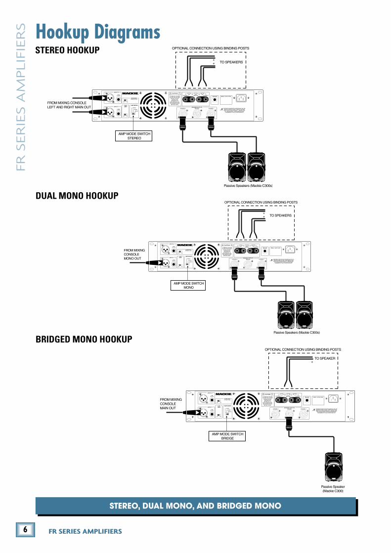
Stereo Hookup
DuAL Mono Hookup
BriDgeD Mono Hookup
FROM MIXING CONSOLELEFT AND RIGHT MAIN OUT
AMP MODE SWITCHSTEREO
Passive Speakers (Mackie C300s)
TO SPEAKERS++
OPTIONAL CONNECTION USING BINDING POSTS
FROM MIXINGCONSOLEMONO OUT
AMP MODE SWITCHMONO
Passive Speakers (Mackie C300s)
TO SPEAKERS++
OPTIONAL CONNECTION USING BINDING POSTS
FROM MIXINGCONSOLEMAIN OUT
AMP MODE SWITCHBRIDGE
Passive Speaker(Mackie C300)
TO SPEAKER+
OPTIONAL CONNECTION USING BINDING POSTS

7Owner’s Manual
Ow
ne
r’s Man
ual
DAISY CHAINING AND A CUTE TRICK
DAiSY CHAining tWo AMpLiFierS
FROM MIXING CONSOLE
LEFT AND RIGHT MAIN OUT
AMP MODE SWITCH
STEREO
Passive Speakers (Mackie C300s)
Crossover Cable
(Pin 2+ to Pin 1+
Pin 2– to Pin 1–)
COLD
COLD
AMPLIFIER
END
SPEAKER
END
HOT
CHANNEL A
CHANNEL B
1+
1–
2–
2+1+
1–
2–
2+
COLD
FROM "THRU"
OUTPUT
TO SECOND
SPEAKER INPUT
FROM "THRU"
OUTPUT
TO SECOND
SPEAKER INPUT
TO FIRST
SPEAKER INPUT
HOT
CHANNEL B
1+
1–
2–
2+1+
1–
2–
2+
FROM MIXING CONSOLELEFT AND RIGHT MAIN OUT
AMP MODE SWITCHSTEREO
Passive Speakers (Mackie C300s)
AMP MODE SWITCHSTEREO
Passive Speakers (Mackie C300s)
running Stereo SpeAkerS WitH MiniMuM SpeAker CABLe runS
8 FR SERIES AMPLIFIERS
FR S
ER
IES A
MPLIF
IER
S
124
5
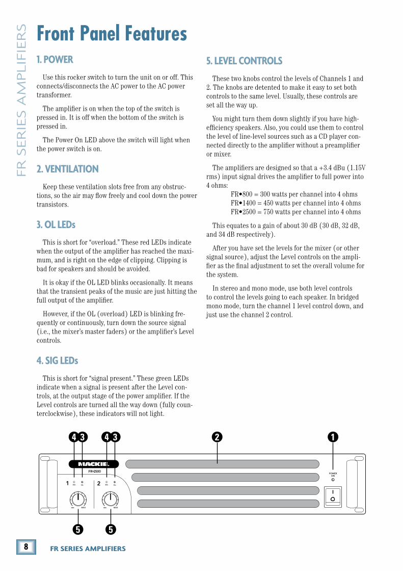
Front Panel Features1. POWER
Use this rocker switch to turn the unit on or off. This connects/disconnects the AC power to the AC power transformer.
The amplifier is on when the top of the switch is pressed in. It is off when the bottom of the switch is pressed in.
The Power On LED above the switch will light when the power switch is on.
�. VENTILATION
Keep these ventilation slots free from any obstruc-tions, so the air may flow freely and cool down the power transistors.
�. OL LEDs
This is short for “overload.” These red LEDs indicate when the output of the amplifier has reached the maxi-mum, and is right on the edge of clipping. Clipping is bad for speakers and should be avoided.
It is okay if the OL LED blinks occasionally. It means that the transient peaks of the music are just hitting the full output of the amplifier.
However, if the OL (overload) LED is blinking fre-quently or continuously, turn down the source signal (i.e., the mixer’s master faders) or the amplifier’s Level controls.
4. SIG LEDs
This is short for “signal present.” These green LEDs indicate when a signal is present after the Level con-trols, at the output stage of the power amplifier. If the Level controls are turned all the way down (fully coun-terclockwise), these indicators will not light.
5. LEVEL CONTROLS
These two knobs control the levels of Channels 1 and 2. The knobs are detented to make it easy to set both controls to the same level. Usually, these controls are set all the way up.
You might turn them down slightly if you have high-efficiency speakers. Also, you could use them to control the level of line-level sources such as a CD player con-nected directly to the amplifier without a preamplifier or mixer.
The amplifiers are designed so that a +3.4 dBu (1.15V rms) input signal drives the amplifier to full power into 4 ohms: FR•800 = 300 watts per channel into 4 ohms FR•1400 = 450 watts per channel into 4 ohms FR•2500 = 750 watts per channel into 4 ohms
This equates to a gain of about 30 dB (30 dB, 32 dB, and 34 dB respectively).
After you have set the levels for the mixer (or other signal source), adjust the Level controls on the ampli-fier as the final adjustment to set the overall volume for the system.
In stereo and mono mode, use both level controls to control the levels going to each speaker. In bridged mono mode, turn the channel 1 level control down, and just use the channel 2 control.
34 3
5
9Owner’s Manual
Ow
ne
r’s Man
ual
7 8
9 10
6
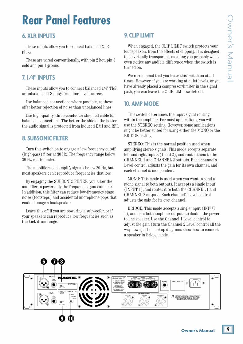
Rear Panel Features6. XLR INPUTS
These inputs allow you to connect balanced XLR plugs.
These are wired conventionally, with pin 2 hot, pin 3 cold and pin 1 ground.
7. 1/4" INPUTS
These inputs allow you to connect balanced 1/4" TRS or unbalanced TS plugs from line-level sources.
Use balanced connections where possible, as these offer better rejection of noise than unbalanced lines.
Use high-quality, three-conductor shielded cable for balanced connections. The better the shield, the better the audio signal is protected from induced EMI and RFI.
8. SUBSONIC FILTER
Turn this switch on to engage a low-frequency cutoff (high-pass) filter at 30 Hz. The frequency range below 30 Hz is attenuated.
The amplifiers can amplify signals below 20 Hz, but most speakers can’t reproduce frequencies that low.
By engaging the SUBSONIC FILTER, you allow the amplifier to power only the frequencies you can hear. In addition, this filter can reduce low-frequency stage noise (footsteps) and accidental microphone pops that could damage a loudspeaker.
Leave this off if you are powering a subwoofer, or if your speakers can reproduce low frequencies such as the kick drum range.
9. CLIP LIMIT
When engaged, the CLIP LIMIT switch protects your loudspeakers from the effects of clipping. It is designed to be virtually transparent, meaning you probably won’t even notice any audible difference when the switch is turned on.
We recommend that you leave this switch on at all times. However, if you are working at quiet levels, or you have already placed a compressor/limiter in the signal path, you can leave the CLIP LIMIT switch off.
10. AMP MODE
This switch determines the input signal routing within the amplifier. For most applications, you will use the STEREO setting. However, some applications might be better suited for using either the MONO or the BRIDGE setting.
STEREO: This is the normal position used when amplifying stereo signals. This mode accepts separate left and right inputs (1 and 2), and routes them to the CHANNEL 1 and CHANNEL 2 outputs. Each channel’s Level control adjusts the gain for its own channel, and each channel is independent.
MONO: This mode is used when you want to send a mono signal to both outputs. It accepts a single input (INPUT 1), and routes it to both the CHANNEL 1 and CHANNEL 2 outputs. Each channel’s Level control adjusts the gain for its own channel.
BRIDGE: This mode accepts a single input (INPUT 1), and uses both amplifier outputs to double the power to one speaker. Use the Channel 1 Level control to adjust the gain (turn the Channel 2 Level control all the way down). The hookup diagrams show how to connect a speaker in Bridge mode.

10 FR SERIES AMPLIFIERS
FR S
ER
IES A
MPLIF
IER
S 11. FAN VENTS
Do not obstruct the ventilation openings of the ampli-fier.
1�. SPEAKER OUTPUTS
There are two options for connecting your speakers: binding posts and Speakon connectors.
Normally, you would use either the binding posts or the Speakon connectors. Since the connectors are wired in parallel (e.g., CHANNEL 1 binding post and Speakon are in parallel, and CHANNEL 2 binding post and Speakon are in parallel), you can connect a speaker to each connector, as long as the total impedance per channel is two ohms or more.
• Two 8 ohm speakers in parallel equals 4 ohms.
• Two 4 ohm speakers in parallel equals 2 ohms.
When the amplifier is used in bridged mono mode, use either the center Speakon, or the two red binding posts to connect your single speaker.
1�. BREAKER
This is a resettable circuit breaker that monitors the amount of current being drawn by the amplifier. Under normal operating conditions, this should never pop. An unusual condition may cause the breaker to pop, such as a mains voltage surge occurring at the same time as a peak amplifier output.
Turn the POWER switch off, and push the BREAKER button in to reset the circuit breaker. Turn the POWER switch back on and the amplifier should resume normal operation. If the circuit breaker pops again, something probably isn’t right.
• Make sure that the total impedance of the speakers connected to the outputs is 2 ohms or greater (per channel) in stereo mode, or 4 ohms or greater in bridged mode.
• If the breaker pops right away, even with the Level controls turned down and the speakers disconnected, there may be something wrong inside the amplifier.
• There are no user-serviceable parts inside. Please refer to the “Repair” section on page 13 for instructions on how to proceed.
14. POWER CORD SOCKET
Here is where you connect the detachable power cord included with your amplifier. Plug the other end of the power cord into an AC outlet properly configured with the voltage required for your particular model.
Be sure the AC outlet can supply enough current to allow full power operation of all the amplifiers plugged into it. The outlet should be a three-prong socket that matches the power cord.
14131211
11Owner’s Manual
Ow
ne
r’s Man
ual
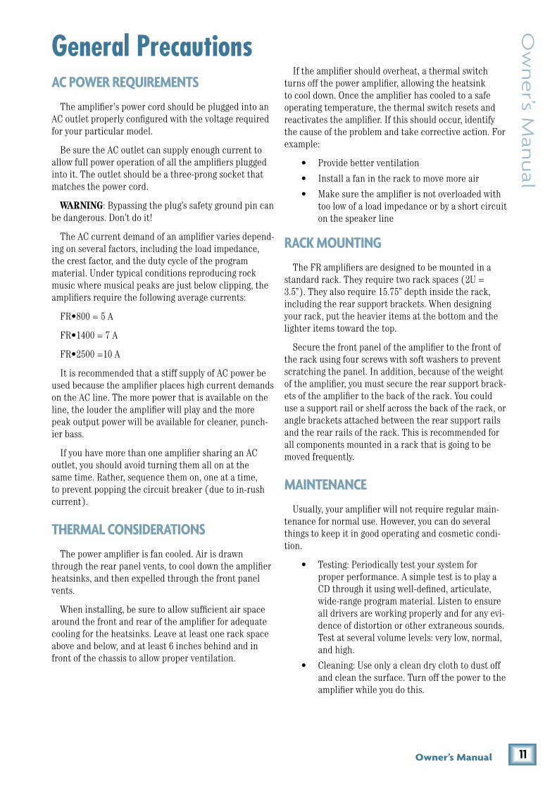
General PrecautionsAC POWER REQUIREMENTS
The amplifier's power cord should be plugged into an AC outlet properly configured with the voltage required for your particular model.
Be sure the AC outlet can supply enough current to allow full power operation of all the amplifiers plugged into it. The outlet should be a three-prong socket that matches the power cord.
WARNING: Bypassing the plug’s safety ground pin can be dangerous. Don’t do it!
The AC current demand of an amplifier varies depend-ing on several factors, including the load impedance, the crest factor, and the duty cycle of the program material. Under typical conditions reproducing rock music where musical peaks are just below clipping, the amplifiers require the following average currents:
FR•800 = 5 A
FR•1400 = 7 A
FR•2500 =10 A
It is recommended that a stiff supply of AC power be used because the amplifier places high current demands on the AC line. The more power that is available on the line, the louder the amplifier will play and the more peak output power will be available for cleaner, punch-ier bass.
If you have more than one amplifier sharing an AC outlet, you should avoid turning them all on at the same time. Rather, sequence them on, one at a time, to prevent popping the circuit breaker (due to in-rush current).
THERMAL CONSIDERATIONS
The power amplifier is fan cooled. Air is drawn through the rear panel vents, to cool down the amplifier heatsinks, and then expelled through the front panel vents.
When installing, be sure to allow sufficient air space around the front and rear of the amplifier for adequate cooling for the heatsinks. Leave at least one rack space above and below, and at least 6 inches behind and in front of the chassis to allow proper ventilation.
If the amplifier should overheat, a thermal switch turns off the power amplifier, allowing the heatsink to cool down. Once the amplifier has cooled to a safe operating temperature, the thermal switch resets and reactivates the amplifier. If this should occur, identify the cause of the problem and take corrective action. For example:
• Provide better ventilation
• Install a fan in the rack to move more air
• Make sure the amplifier is not overloaded with too low of a load impedance or by a short circuit on the speaker line
RACK MOUNTING
The FR amplifiers are designed to be mounted in a standard rack. They require two rack spaces (2U = 3.5”). They also require 15.75” depth inside the rack, including the rear support brackets. When designing your rack, put the heavier items at the bottom and the lighter items toward the top.
Secure the front panel of the amplifier to the front of the rack using four screws with soft washers to prevent scratching the panel. In addition, because of the weight of the amplifier, you must secure the rear support brack-ets of the amplifier to the back of the rack. You could use a support rail or shelf across the back of the rack, or angle brackets attached between the rear support rails and the rear rails of the rack. This is recommended for all components mounted in a rack that is going to be moved frequently.
MAINTENANCE
Usually, your amplifier will not require regular main-tenance for normal use. However, you can do several things to keep it in good operating and cosmetic condi-tion.
• Testing: Periodically test your system for proper performance. A simple test is to play a CD through it using well-defined, articulate, wide-range program material. Listen to ensure all drivers are working properly and for any evi-dence of distortion or other extraneous sounds. Test at several volume levels: very low, normal, and high.
• Cleaning: Use only a clean dry cloth to dust off and clean the surface. Turn off the power to the amplifier while you do this.

1� FR SERIES AMPLIFIERS
FR S
ER
IES A
MPLIF
IER
S Appendix A: Service Information• Is the signal source turned up? Make sure
the signal level from the mixing console (or whatever device immediately precedes the amplifier) is high enough to produce sound in the amplifier. The SIG LEDs should be blinking to indicate that signal is present.
• If the speakers are wired for BRIDGE mode, make sure the AMP MODE switch is set to BRIDGE.
• If the amplifier has gotten extremely hot, the thermal protection circuit may have activated. Allow the amplifier to cool down and normal operation should resume.
• Are there fuses in the speakers, or in-line fuses in the speaker wire? Check to see if they’re blown.
Distorted Sound
• The power amplifier is clipping. The signal level is exceeding the limits of your system and you must reduce the level from your mixer or signal source.
• Ensure that no equipment in the signal chain is being over driven. For example: input(s) or summing bus in the mixing console, equalizers etc.
• Is the input connector plugged completely into the jack? Check the speaker connections and verify that all connections are tight and that there are no stray strands of wire shorting across the speaker terminals.
• If possible, listen to the signal source with headphones plugged into the console. If it sounds bad there, the problem is not in the amplifier.
• Loudspeakers not working properly.
Partial Sound (frequency band missing)
• Incorrect EQ settings in the electronic equip-ment. Ensure all EQ settings and filters on the mixing console or preamplifier and on other equipment are set for normal operation. Ensure level controls on electronic crossovers and as-sociated amplifiers are correctly set and that all cables and connections for such equipment are connected and working properly.
• Loudspeaker not working properly. Swap with a good one.
• Is the LED next to the POWER switch illumi-nated? If not, make sure the AC outlet is live.
• The fuses inside the amplifier may have blown. These are not a user-serviceable. See next page about service.
Warranty ServiceDetails concerning Warranty Service are spelled out
in the Warranty section on page 19.
If you think your amplifier has a problem, please do everything you can to confirm it before calling for service. Doing so might save you from the deprivation of your amplifier.
These may sound obvious to you, but here are some things you can check. Read on:
TroubleshootingNo Power
• Our favorite question: Is it plugged in?
• Make sure the power cord is securely seated in the IEC socket and plugged all the way into the AC outlet.
• Make sure the AC outlet is live (check with a tester or lamp).
• Make sure the front panel POWER switch is in the ON position.
• Has the BREAKER switch popped?
• Is anything on the front panel illuminated? If not, make sure the AC outlet is live.
• Are all the lights out in your town? If so, contact your local power company to get power restored.
• If nothing is illuminated, and you are certain that the AC outlet is live, it will be necessary to have your amplifier serviced. There are no user serviceable parts inside. Refer to “Repair” on the next page to find out how to proceed.
No Sound or Low Output
• Loudspeaker cables or connectors are not wired correctly or they are faulty. Check all cabling, referring to these instructions for the correct connections. The best way to check a suspect cable is to swap it with a known good cable. Read the loudspeaker’s input panel to verify correct cable connections.
• Loudspeaker is not working. Connect the loudspeaker cable to a known good loudspeaker leaving all equipment set to the same levels. If the problem disappears, the loudspeaker is probably not working correctly.
• Are the channel Level controls turned up? Slowly turn them up and see if you hear any-thing.
1�Owner’s Manual
Ow
ne
r’s Man
ual
One side is louder than the other
• Are both Level controls set to the same posi-tion?
• Check your source signal to make sure the left and right signals are balanced.
• Are the speaker impedances matched? Differ-ent speaker loads can cause different volume levels on each side.
• Try switching sides: Turn off the amp, swap the speaker cables at the amp, turn the amp back on. If the same side is still louder, the problem is with your speaker cabling. If the other side is louder now, the problem is with the mixer, the amp, or the line-level cabling.
Poor Bass response
• Check the polarity of the speaker cable connec-tions. You may have your positive and negative reversed at one end of one speaker cable.
As the music gets loud, the amp shuts down
• Make sure the OL LEDs are not lighting con-tinuously. If so, turn down the signal source or the amp Level controls.
• Can the amp breathe? It needs plenty of fresh air to stay cool. Do not block the ventilation holes.
Noise/Hum
• Check the signal cable between the mixer and the amplifier. Make sure all connections are good and sound.
• Make sure the signal cable is not routed near AC cables, power transformers, or other EMI-inducing devices.
• Is there a light dimmer or other SCR-based device on the same AC circuit as the amplifier? Use an AC line filter, or plug the amplifier into a different AC circuit.
• If possible, listen to the signal source with headphones plugged into the console. If it sounds noisy there, the problem is not in the amplifier.
• Is there a cable-TV audio feed in your system? An incorrect ground may causes a "ground loop" hum.
• Sometimes it helps to plug all the audio equip-ment into the same AC circuit so they share a common ground.
RepairService for Mackie products is available at a factory-authorized service center. Service for Mackie products living outside the United States can be obtained through local dealers or distributors.
If your amplifier needs service, follow these instructions:
1. Review the preceding troubleshooting suggestions. Please.
2. Call Tech Support at 1-800-898-3211, 7 am to 5 pm PST, to explain the problem and request a Service Request Number. Have your serial number ready. You must have a Service Request Number before you can obtain warranty service.
3. Keep this owner’s manual and the detachable linecord. We don’t need them to repair the amp.
4. Pack the amplifier in its original package, includ-ing endcaps and box. This is VERY IMPORTANT. Mackie is not responsible for any damage that oc-curs due to non-factory packaging.
5. Include a legible note stating your name, shipping address (no P.O. boxes), daytime phone number, Service Request Number, and a detailed description of the problem, including how we can duplicate it.
6. Write the Service Request Number in BIG PRINT on top of the box. Units sent without the SR number will be refused.
7. Tech Support will tell you where to ship the ampli-fier for repair. We suggest insurance for all forms of cartage.
8. You will need to contact the authorized service center for their latest turn-around times. Once it’s repaired, the authorized service center will ship it back by ground shipping, pre-paid (if it was a war-ranty repair).
Note: Under the terms of the warranty, you must ship or drop-off the unit to an authorized service center. The return ground shipment is covered for those units deemed by us to be under warranty.
Note: You must have a sales receipt from an authorized Mackie dealer for your unit to be considered for warranty repair.

14 FR SERIES AMPLIFIERS
FR S
ER
IES A
MPLIF
IER
S Appendix B: Connections, math and stuff1/4" TS Phone Plugs and Jacks
“TS” stands for Tip-Sleeve, the two connections avail-able on a mono 1/4" phone jack or plug. They are used for unbalanced signals.
1/4" TS Unbalanced Wiring
Sleeve = Shield Tip = Hot (+)
SpeakonsWhen using the Speakon outputs in stereo or mono
modes, wire the Speakon connectors as shown below:
Stereo and Mono Speakon Connection
Loudspeaker CableUse loudspeaker cables with a minimum conductor
size for the length you need as listed in these tables.
This will minimize power losses to less than 0.5 dB. The ca-ble lengths listed are “up to” lengths. For in-between lengths, use the next larger conductor gauge. Using larger than the recommended con-ductor size is always permissible. Using smaller than recom-mended conductor size will result in higher power losses.
The recommended conductor gauges are listed for AWG (American Wire Gauge) and Metric WG (Metric Wire Gauge). Note that smaller AWG numbers = larger
2
2
3 1
1
SHIELD
COLD
HOT
SHIELD
COLD
HOT
3
SHIELD
COLDHOT
3
2
1
SLEEVE
TIPSLEEVE
TIP
RING
RING
TIP
SLEEVERING
SLEEVE
TIP
TIPSLEEVE
TIP
SLEEVE
Minimum AWG 4 ohm 8 ohm
18 10 ft 25 ft
16 25 50
14 25 75
12 50 125
10 100 200
Min Metric WG 4 ohm 8 ohm
12 3 m 8 m
14 8 15
16 8 25
20 15 40
25 30 60
COLD
HOT1+
1+
1–
1–
2–2+
Use a high-quality 3-conductor shielded cable to connect the signal between the signal source (mixing console, equalizer, etc.) and the balanced inputs to the amplifier. If you are using unbalanced inputs, use a high-quality 2-conductor shielded cable. Here are some common audio connectors and their internal wiring:
XLR ConnectorsXLR connectors are commonly wired as follows (ac-
cording to standards specified by the Audio Engineering Society):
XLR Balanced Wiring
Pin 1 = Shield Pin 2 = Hot (+) Pin 3 = Cold (–)
1/4" TRS Phone Plugs and Jacks
“TRS” stands for Tip-Ring-Sleeve, the three connec-tions available on a stereo 1/4" or balanced phone jack or plug. TRS jacks and plugs are used for balanced signals and stereo headphones.
1/4" TRS Balanced wiring
Sleeve = Shield Tip = Hot (+) Ring = Cold (–)

15Owner’s Manual
Ow
ne
r’s Man
ual
conductors and smaller Metric WG numbers = smaller conductors. The Metric WG is equal to ten times the nominal conductor diameter in millimeters.
Longer Lengths
For cable lengths over 200 feet / 60 m at 8 ohms, and over 100 feet / 30 m at 4 ohms, the conductor sizes needed for less than 0.5 dB power losses are rarely prac-tical for physical and cost reasons.
As a practical compromise for these situations the recommended conductor gauge is 10 AWG or 25 metric.
Speaker ImpedancesA speaker’s impedance varies with frequency. For ex-
ample, it may be 4 ohms at 500Hz, and 6 ohms at 120Hz. What you need to know is the average (or nominal) impedance across the speaker’s frequency range. This will be printed somewhere on the cabinet, or in the specification section of the missing manual.
If you’re just dealing with one speaker per channel, then make sure that the average impedance is greater than or equal to 2 ohms.
In BRIDGE MONO mode, make sure that your speaker impedance is greater than or equal to 4 ohms.
If you’re driving an assortment of speakers, you have to make sure that the total impedance does not go below these same levels. There are two basic ways of linking multiple speakers: series and parallel. The following sections show how to make the connections and how to work out the total impedance.
SERIES
“Series” means that the positive amp output con-nects to the first speaker’s positive terminal, the first speaker’s negative terminal connects to the second speaker’s positive terminal, the second speaker’s nega-tive terminal goes to the amp’s negative output. Series connections are not normally used in PA applications because it ruins the amplifier’s ability to damp (control) the speakers. The other snag: if one speaker goes out, they all do.
Doing load calculations with series configurations is easy — just add the loads. For instance, two 4-ohm speakers in series, equals 8 ohms (4 + 4 = 8).
PARALLEL
“Parallel” means that the positive amp output con-nects to the positive terminals of all the speakers, and the negative amp output connects to the negative
terminals of all the speakers. If one speaker opens in a parallel configuration, the others will still work, but the load will change. That lets you breathe a little easier (the show will go on), except that you may have a dead speaker and not even know it.
Calculating parallel loads is also easy, as long as each speaker has the same value — just divide the value by the number of speakers.
For example, four 8-ohm speakers, connected in par-allel, will equal 2 ohms (8 / 4 = 2).
If the parallel loads aren’t all the same, things gets a little more complicated, but nothing that you can’t do with a simple calculator. The total impedance (ZT) is given by the following formula, where Z1, Z2 and Z3 are the impedances of your speakers.
There are other, more complicated configurations, like series-parallel (using a combination of series and paral-lel links to arrive at a desired load) and parallel configu-rations of unmatched loads (usually not recommended). But rather than get too deep into this, let’s just summa-rize the basics, as they apply to you and your amp:
• The lower the speaker impedance, the more power can be put out by the amplifier.
• Driving lower impedance speakers makes the amplifier work harder and heat up quicker.
• Do not connect a total impedance of under 2 ohms per channel in STEREO and MONO modes.
• Do not connect a total impedance of under 4 ohms in BRIDGE mode.
• Connecting speakers in series or parallel can drastically alter their frequency response.
• Consider using multiple amplifiers rather than overloading one.
• Reduce the low-frequency output by setting the LOW CUT FILTER to match the speaker’s specifications.
• Never plug the amplifier outputs into anything except speakers (unless you have an outboard box designed to accept speaker level levels).
• Be careful in BRIDGE mode as both speaker wires are live. In this mode, do not connect the speaker wires to any external device which is grounded.
ZT = 1
1Z1
+ 1Z2
+ 1Z3
+ . . .

16 FR SERIES AMPLIFIERS
FR S
ER
IES A
MPLIF
IER
S Appendix C: Technical Info
TopologyFR•800, FR•1400: Class AB
FR•2500: Class H
CoolingVariable-speed fans with back to front airflow
IndicatorsChannels A and B SIG (Signal Present), OL (Overload), POWER
Current Consumption FR•800 FR•1400 FR•2500
Idle 0.5 A 0.5 A 1.0 A
Musical Program @ 8 ohms 3.9 A 5.1 A 8.1 A
Musical Program @ 4 ohms 5.0 A 6.7 A 10.0 A
Musical Program @ 2 ohms 7.0 A 10.6 A 17.2 A
AC Power RequirementsU.S model: 120 VAC, 60 Hz
European model: 240 VAC, 50 Hz
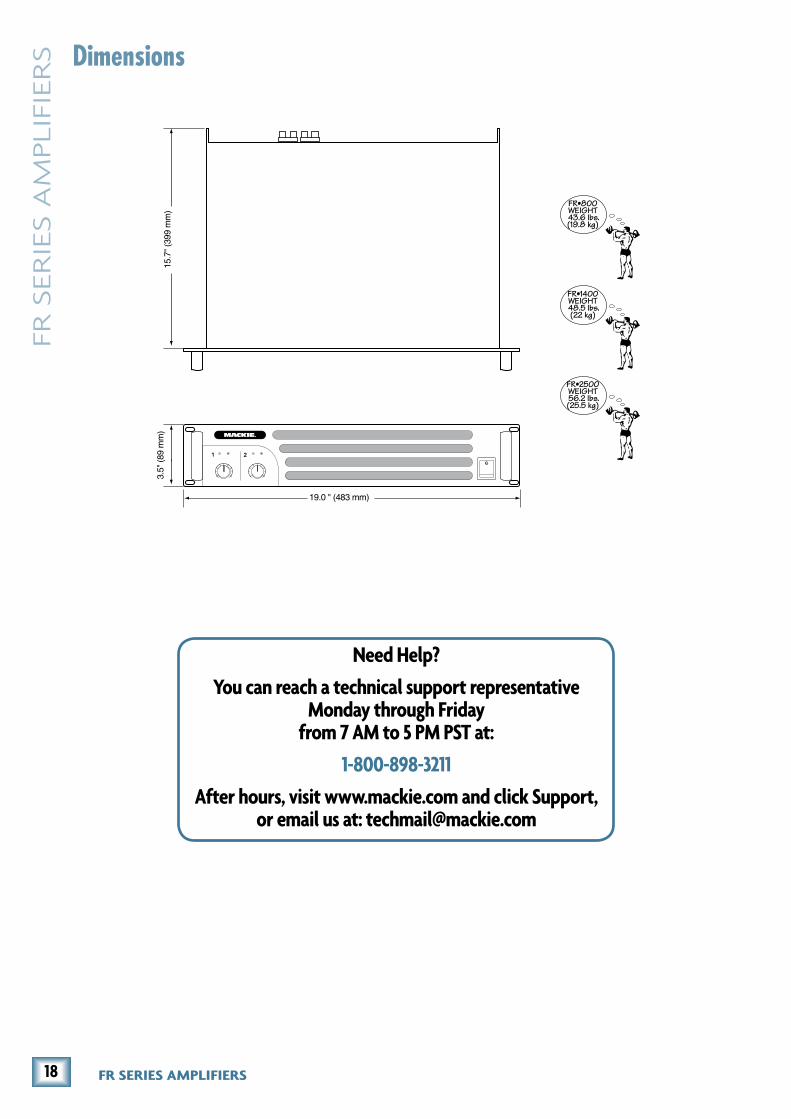
Physical Dimensions and WeightHeight: 3.5 in/89 mm
Width: 19.0 in/483 mm
Depth: 15.7 in/400 mm
Weight:
FR•800: 43.6 lb/19.8 kg
FR•1400: 48.5 lb/22.0 kg
FR•2500: 56.2 lb/25.5 kg
LOUD Technologies Inc. is always boldly striving to improve our products by incorporating new and improved materi-als, components, and manufacturing methods. Therefore, we reserve the right to change these specifications at any time without notice.
“Mackie,” and the “Running Man” are registered trademarks of LOUD Technologies Inc. All other brand names mentioned are trademarks or registered trademarks of their respective hold-ers, and are hereby acknowledged.
The technical writer reserves the right to go downstairs and get a bag of popcorn, shoot the breeze and exchange tech writer jokes with his buddies around the water cooler.
Betty darling, I will always love you. I’m leaving now to go and rethink my life, get some lunch and a brake cable for the old Chevette. All I can hope for is that your new Beau is as reliable and dependable as these amplifiers.
©2006 LOUD Technologies Inc. All Rights Reserved.
SpecificationsContinuous Sine Wave Average Output Power, per channel, both channels driven, �0 Hz to �0 kHz
FR•800 FR•1400 FR•2500
2 ohms: 480 W 800 W 1400 W
4 ohms: 300 W 450 W 750 W
8 ohms: 205 W 310 W 575 W
Bridged Mono Operation, �0 Hz to �0 kHz
FR•800 FR•1400 FR•2500
4 ohms: 800 W 1400 W 2500 W
8 ohms: 560 W 900 W 1500 W
Note: Power ratings are specified at 120 VAC line voltage.
Power Bandwidth5 Hz to 50 kHz (+0, –3 dB)
Frequency Response25 Hz to 25 kHz (+0, –1 dB)
DistortionTHD and SMPTE IMD; 20 Hz to 20 kHz < 0.03 % @ 8 ohms
Signal-to-Noise Ratio> 100 dB below rated power into 4 ohms
Channel Separation> 90 dB @ 1 kHz
Damping Factor> 300 @ 1 kHz and below
Input Impedance20 kΩ balanced
10 kΩ unbalanced
Input Sensitivity1.15 V (+3.4 dBu) for rated power into 4 ohms
GainFR•800: 30 dB
FR•1400: 32 dB
FR•2500: 34 dB
Maximum Input Level9.75 Vrms (+22 dBu)
Turn On Delay2.5 seconds
Subsonic Filter– 9 dB @ 30 Hz
17Owner’s Manual
Ow
ne
r’s Man
ual
1+
1–
2–
2+
1+
1–2–
2+
INP
UT
AB
ALA
NC
ED
LIN
E IN
PU
T(T
RS
)
INP
UT
AB
ALA
NC
ED
LIN
E IN
PU
T(X
LR-F
)
INP
UT
BB
ALA
NC
ED
LIN
E IN
PU
T(T
RS
) FR
SE
RIE
SB
LOC
K D
IAG
RA
M28
.12.
05
INP
UT
BB
ALA
NC
ED
LIN
E IN
PU
T(X
LR-F
)
AM
PM
OD
ES
WIT
CH
ST
ER
EO
MO
NO
BR
IDG
E
ST
ER
EO
MO
NO
BR
IDG
E
ST
ER
EO
MO
NO
BR
IDG
E
12 3
12 3
CH
AN
NE
L A
LEV
EL
CH
AN
NE
L B
LEV
EL
SU
BS
ON
ICF
ILT
ER
ON
OF
F
ON
OF
F
ON
OF
F
ON
PR
OT
EC
TIO
ND
C O
FF
SE
TO
VE
R T
EM
PS
HO
RT
CIR
CU
ITC
UR
RE
NT
LIM
IT
OF
F
CLI
PLI
MIT
ER
OL
PO
WE
R
AM
PLI
FIE
R
–VD
C
+VD
C
CH
AN
NE
L A
SP
EA
KE
RO
UT
BR
IDG
ED
SP
EA
KE
RO
UT
1+
1–
2–
2+
PO
WE
R
AM
PLI
FIE
R
–VD
C
+VD
C
CH
AN
NE
L B
SP
EA
KE
RO
UT
OL
SIG
SIG
+ –
+ – + –
+ – + –
+ –V
DC
(CH
AN
NE
L A
)
TOR
OID
AL
PO
WE
RT
RA
NS
FO
RM
ER
BR
EA
KE
R
FU
SE
FU
SE
TE
MP
SE
NS
OR
(ON
HE
ATS
INK
)
FAN
VAR
IAB
LES
PE
ED
C
ON
TR
OL
HI D
CV
HI D
CV
LO D
CV
LO D
CV
PO
WE
RS
WIT
CH
PO
WE
R
+ –V
DC
(CH
AN
NE
L B
)
+ –
FU
SE
FU
SE
FAN
FAN
SPA
CE
MA
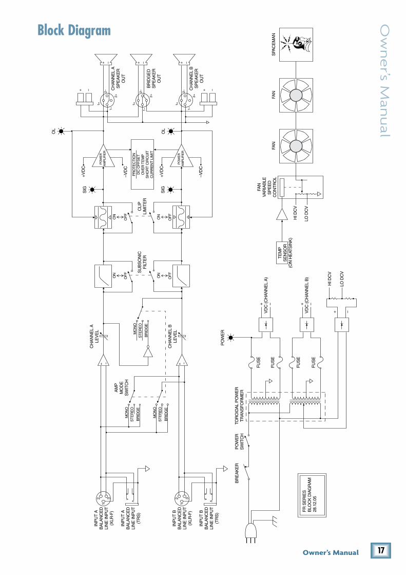
NBlock Diagram
18 FR SERIES AMPLIFIERS
FR S
ER
IES A
MPLIF
IER
S
Need Help?
You can reach a technical support representative Monday through Friday
from 7 AM to 5 PM PST at:
1-800-898-��11
After hours, visit www.mackie.com and click Support, or email us at: [email protected]
19.0 " (483 mm)
15.7
" (3
99 m
m)
FR•800WEIGHT 43.6 lbs.(19.8 kg)
FR•1400WEIGHT 48.5 lbs.(22 kg)
FR•2500WEIGHT 56.2 lbs.(25.5 kg)
3.5"
(89
mm
)
Dimensions

19Owner’s Manual
Ow
ne
r’s Man
ual
A. LOUD Technologies Inc. warrants all materials, workmanship and proper operation of this product for a period of three years from the original date of purchase. If any defects are found in the materials or workmanship or if the product fails to function properly during the applicable warranty period, LOUD Technologies, at its option, will repair or replace the product. This warranty applies only to equipment sold and delivered within the U.S. by LOUD Technologies Inc. or its authorized dealers.B. Failure to register online or return the product registration card will not void the three-year warranty.
C. Service and repairs of Mackie products are to be performed only at a factory-authorized facility (see D below). Unauthorized service, repairs, or modification will void this warranty. To obtain repairs under warranty, you must have a copy of your sales receipt from the authorized Mackie dealer where you purchased the product. It is necessary to establish the purchase date and determine whether your Mackie product is within the warranty period.
D. To obtain factory-authorized service:
1. Call Mackie Technical Support at 800/898-3211, 7 AM to 5 PM Monday through Friday (Pacific Time) to get a Service Request Number. Products returned without a Service Request Number will be refused.
2. Pack the product in its original shipping carton. Also include a note explaining exactly how to duplicate the problem, a copy of the sales receipt with price and date showing, and your return street address (no P.O. boxes or route numbers, please!). If we cannot duplicate the problem or establish the starting date of your Limited Warranty, we may, at our option, charge for service time.
3. Ship the product in its original shipping carton, freight prepaid to the authorized service center. The address of your closest authorized service center will be given to you by Technical Support, or from our website.
IMPORTANT: Make sure that the Service Request Number is plainly written on the shipping carton. No receipt, no warranty service.
E. LOUD Technologies reserves the right to inspect any products that may be the subject of any warranty claims before repair or replacement is carried out. LOUD Technologies may, at our option, require proof of the original date of purchase in the form of a dated copy of the original dealer’s invoice or sales receipt. Final determination of warranty coverage lies solely with LOUD Technologies.
F. Any products returned to one of the LOUD Technologies factory-authorized service centers, and deemed eligible for repair or replacement under the terms of this warranty will be repaired or replaced within thirty days of receipt. LOUD Technologies and its authorized service centers may use refurbished parts for repair or replacement of any product. Products returned to LOUD Technologies that do not meet the terms of this Warranty will not be repaired unless payment is received for labor, materials, return freight, and insurance. Products repaired under warranty will be returned freight prepaid by LOUD Technologies to any location within the boundaries of the USA.
G. LOUD Technologies warrants all repairs performed for 90 days or for the remainder of the warranty period. This warranty does not extend to damage resulting from improper installation, misuse, neglect or abuse, or to exterior appearance. This warranty is recognized only if the inspection seals and serial number on the unit have not been defaced or removed.
H. LOUD Technologies assumes no responsibility for the quality or timeliness of repairs performed by an authorized service center.
I. This warranty is extended to the original purchaser and to anyone who may subsequently purchase this product within the applicable warranty period. A copy of the original sales receipt is required to obtain warranty repairs.
J. This is your sole warranty. LOUD Technologies does not authorize any third party, including any dealer or sales representative, to assume any liability on behalf of LOUD Technologies or to make any warranty for LOUD Technologies Inc.
K. THE WARRANTY GIVEN ON THIS PAGE IS THE SOLE WARRANTY GIVEN BY LOUD TECHNOLOGIES INC. AND IS IN LIEU OF ALL OTHER WARRANTIES, EXPRESS AND IMPLIED, INCLUDING THE WARRANTIES OF MERCHANTABILITY AND FITNESS FOR A PARTICULAR PURPOSE. THE WARRANTY GIVEN ON THIS PAGE SHALL BE STRICTLY LIMITED IN DURATION TO THREE YEARS FROM THE DATE OF ORIGINAL PURCHASE FROM AN AUTHORIZED MACKIE DEALER. UPON EXPIRATION OF THE APPLICABLE WARRANTY PERIOD, LOUD TECHNOLOGIES INC. SHALL HAVE NO FURTHER WARRANTY OBLIGATION OF ANY KIND. LOUD TECHNOLOGIES INC. SHALL NOT BE LIABLE FOR ANY INCIDENTAL, SPECIAL, OR CONSEQUENTIAL DAMAGES THAT MAY RESULT FROM ANY DEFECT IN THE MACKIE PRODUCT OR ANY WARRANTY CLAIM. Some states do not allow exclusion or limitation of incidental, special, or consequential damages or a limitation on how long warranties last, so some of the above limitations and exclusions may not apply to you. This warranty provides specific legal rights and you may have other rights which vary from state to state.
Please keep your sales receipt in a safe place.
FR Series Amplifiers Limited Warranty

16220 Wood-Red Road NE • Woodinville, WA 98072 • USAUnited States and Canada: 800.898.3211Europe, Asia, Central and South America: 425.487.4333Middle East and Africa: 31.20.654.4000Fax: 425.487.4337 • www.mackie.comE-mail: [email protected]