fr notice d’utilisation en user instructions es …
TRANSCRIPT
K500090019_E 04/16
(Notice originale) (Manual original)
(Original instructions)
CONSIGNES DE SECURITE Pour votre sécurité et votre confort d’utilisation, la lecture complète de ce manuel est fortement recommandée. SAFETY PRECAUTIONS For your safety and ease of use, we strongly recommend that you read this manual through completely. CONSIGNAS DE SEGURIDAD Le recomendamos encarecidamente que lea la totalidad de este manual por su seguridad y confort.
FR NOTICE D’UTILISATION EN USER INSTRUCTIONS
ES MANUAL DE UTILIZACION
D3 87ESM


1 FR
INTRODUCTION Madame, Monsieur, Vous venez de faire l’acquisition d’une débroussailleuse et nous vous remercions de votre confiance. Ce manuel a été rédigé pour vous familiariser avec votre nouvelle machine, vous permettre de l’utiliser dans les meilleures conditions et d’effectuer son entretien. Soucieux de vous faire profiter au maximum des évolutions technologiques, des nouveaux équipements ou matériaux et de notre expérience, les modèles sont régulièrement améliorés ; c’est pourquoi les caractéristiques et les renseignements contenus dans ce manuel peuvent être modifiés sans avis préalable et sans obligation de mise à jour. Les illustrations de ce manuel montrent le modèle le plus représentatif pour le sujet traité. En cas de problème ou encore pour toute question relative à la machine, adressez-vous à un revendeur agréé. Conservez ce manuel à portée de main pour le consulter à tout moment et assurez-vous, qu’en cas de revente, il accompagne bien la machine. Aucune reproduction, même partielle, de la présente publication, ne peut se faire sans autorisation écrite préalable. Le catalogue pièces de rechanges ci-joint (en option), est destiné uniquement aux réparateurs agréés
TABLE DES MATIERES
I. CONSIGNES DE SECURITE ................................................................................ 2 II. ETIQUETTES DE SECURITE .............................................................................. 3 III. IDENTIFICATION DE LA MACHINE ................................................................ 4 IV. INFORMATION TECHNIQUES .......................................................................... 4 V. PREPARATION ....................................................................................................... 7 VI. UTILISATION ......................................................................................................... 8 VII. TRANSPORT ........................................................................................................... 9 VIII. ENTRETIEN ............................................................................................................ 9

2 FR
I. CONSIGNES DE SECURITE

3 FR
II. ETIQUETTES DE SECURITE
Votre débroussailleuse doit être utilisée avec prudence. Dans ce but, des étiquettes destinées à vous rappeler les principales précautions d’utilisation ont été placées sur la machine sous forme de pictogrammes. Leur signification est donnée ci-dessous. Ces étiquettes sont considérées comme partie intégrante de la machine. Si l’une d’entre elles se détache ou devient difficile à lire, contactez votre concessionnaire pour la remplacer. Nous vous recommandons également de lire attentivement les consignes de sécurité.
1
2
1- Déconnecter la bougie avant tout entretien de réparation 2- Lire le manuel d’utilisation
Commande d’embrayage avancement
Commande d’embrayage lame
Commande de gaz 1- Rapide 2- Lent
1 2
Commande frein moteur

4 FR
III. IDENTIFICATION DE LA MACHINE
A -Puissance nominale B -Masse en kilogrammes C -Numéro de série D -Année de fabrication E -Type de la débroussailleuse F -Nom et adresse du constructeur G -Marquage de conformité CE H -Vitesse nominale moteur
IV. INFORMATION TECHNIQUES
HONDA GX120
HONDA GC135
HONDA GP 160
B&S 550 SERIES
Poids 73Kg 73Kg 73Kg 71Kg Puissance nette* 2.6 KW 2.7 KW 3.6 KW 2.4 KW Pour un régime moteur 3600 tr/mn 3600 tr/mn 3600 tr/mn 3600 tr/mn Puissance nominale 2.2 KW 2.3 KW 3.0 KW 2.0 KW Régime moteur nominal 2800 tr/mn 2800 tr/mn 2800 tr/mn 2800 tr/mn Niveau de puissance acoustique garantie
100 dB(A) 100 dB(A) 96 dB(A) 100 dB(A)
Niveau de pression acoustique au poste de conduite
92 dB(A) 92.2 dB(A) 95 dB(A) 92.5 dB(A)
Incertitude de mesure ± 1 dB(A) ± 1 dB(A) ± 1 dB(A) ± 1 dB(A) Niveau de puissance acoustique mesurée
77 dB(A) 82.8 dB(A) 84 dB(A) 82 dB(A)
Incertitude de mesure ± 1 dB(A) ± 1 dB(A) ± 1 dB(A) ± 1 dB(A) Niveau de vibration au main de l’opérateur
7 m/s² 6.5 m/s² 7 m/s² 6.8 m/s²
Incertitude de mesure
± 0.1m/s² ± 0.1m/s² ± 0.1m/s² ± 0.1m/s²
* La puissance du moteur indiquée dans ce document est une puissance nette obtenue par l’essai d’un moteur de série selon la norme SAE J 1349 à une vitesse de rotation donnée. La puissance d’un autre moteur de production peut être différente de cette valeur indiquée. La puissance réelle d’un moteur installé sur une machine dépendra de différents facteurs comme la vitesse de rotation, les conditions de température, l’humidité, de pression atmosphérique, de maintenance et autres.

5 FR
Accessoires : Pour votre sécurité il est formellement interdit de monter tout autre accessoire que ceux spécifiquement conçus pour votre modèle et type de débroussailleuse. (Listés ci-dessous) - Roues increvables KZ04040005- KZ04040006
QUELQUES CONSEILS D’UTILISATIONS, D’ENTRETIEN ET DE REGLAGE DE VOTRE MOTOFAUCHEUSE. 1 - Section maximum à couper : 15 mm. 2 - Réglage vitesse moteur maximum : 2800 tr/minute. 3 - Dans les pentes, il est déconseillé de laisser redescendre la machine enroue libre (en arrière ou en avant) et de rembrayer brutalement occasionnant un chocs violents sur la roue polyamide à l’intérieur du mécanisme (détérioration non couverte par la garantie). 4 - En cas de saut de la courroie d’avancement: - Vérifier la bonne perpendicularité du galet en appui par rapport au dos de la courroie. - Vérifier la tension de cette courroie 5 - En cas de casse de l’entraîneur : - Régime moteur trop important. - Manque de jeu entre la lame et le porte lame - Mauvais réglage du mouvement latéral par rapport au cardan et à l’excentrique 6 - Lors du changement de la roue polyamide dans le mécanisme d’entraînement veiller à 1 rotation libre (sans effort) au niveau de l’arbre de roue, sinon, à l’aide d’un tournevis repousser les paliers coté arbre de roue pour libérer les contraintes entre les 2 pignons.
6 FR
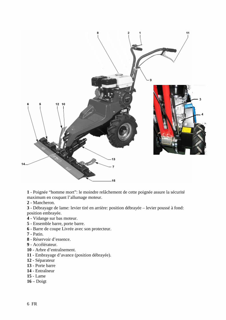
1 - Poignée “homme mort”: le moindre relâchement de cette poignée assure la sécurité maximum en coupant l’allumage moteur. 2 - Mancheron. 3 - Débrayage de lame: levier tiré en arrière: position débrayée – levier poussé à fond: position embrayée. 4 - Vidange sur bas moteur. 5 - Ensemble barre, porte barre. 6 - Barre de coupe Livrée avec son protecteur. 7 - Patin. 8 - Réservoir d’essence. 9 - Accélérateur. 10 - Arbre d’entraînement. 11 - Embrayage d’avance (position débrayée). 12 - Séparateur 13 - Porte barre 14 - Entraîneur 15 - Lame 16 – Doigt
7 FR
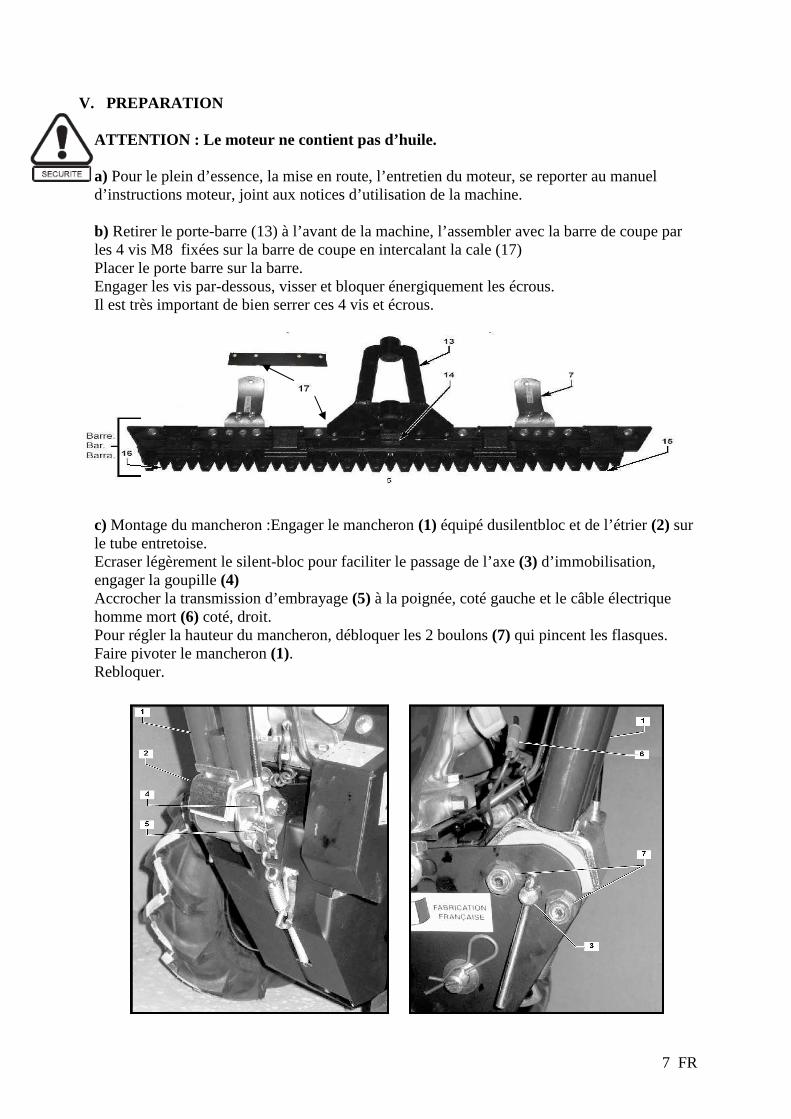
V. PREPARATION ATTENTION : Le moteur ne contient pas d’huile. a) Pour le plein d’essence, la mise en route, l’entretien du moteur, se reporter au manuel d’instructions moteur, joint aux notices d’utilisation de la machine. b) Retirer le porte-barre (13) à l’avant de la machine, l’assembler avec la barre de coupe par les 4 vis M8 fixées sur la barre de coupe en intercalant la cale (17) Placer le porte barre sur la barre. Engager les vis par-dessous, visser et bloquer énergiquement les écrous. Il est très important de bien serrer ces 4 vis et écrous. c) Montage du mancheron :Engager le mancheron (1) équipé dusilentbloc et de l’étrier (2) sur le tube entretoise. Ecraser légèrement le silent-bloc pour faciliter le passage de l’axe (3) d’immobilisation, engager la goupille (4) Accrocher la transmission d’embrayage (5) à la poignée, coté gauche et le câble électrique homme mort (6) coté, droit. Pour régler la hauteur du mancheron, débloquer les 2 boulons (7) qui pincent les flasques. Faire pivoter le mancheron (1). Rebloquer.

8 FR
d) Réglage différentiel e) Réglage hauteur de coupe (minimum 3cm). Régler la hauteur de coupe grâce aux patins orientables. La coupe est d’autant meilleure que la barre est près du sol. Bloquer correctement les patins dans la position choisie.
VI. UTILISATION I. Contrôle avant utilisation
- S’assurer que les 4 boulons (16) maintenant la barre sont bien bloqués, ainsi que les 2 boulons reliant la lame à son entraîneur. - Ne faucher qu’avec une lame en bon état et bien affûtée. Nous vous rappelons que chaque section de lame peut être remplacée séparément. - Ne pas travailler avec une section mal rivée et qui bouge.
II. Utilisation
- Débrayer l’avance de la machine. La poignée d’embrayage est en position ouverte lorsque la machine est débrayée. - Débrayer la lame en tirant vers l’arrière le levier côté droit en bas. - Tenir la poignée “homme mort” plaquée sur le mancheron. - Mettre l’accélérateur en position lièvre (starter). - Tirer énergiquement le lanceur pour obtenir le démarrage (si vous n’obtenez pas le démarrage voir la notice moteur). - Quitter la position starter pour vous placer en position accélérateur. La machine est prête à faucher. - Embrayer la lame en poussant vers l’avant le levier côté droit en bas, embrayer l’avance et la maintenir en position par la poignée. Pour les déplacements à vide, débrayer la lame. - Pour les travaux de finition délicats, manoeuvrer la motofaucheuse à la main.
Différentiel ¾ de tour Différentiel bloqué

9 FR
VII. TRANSPORT
1.
2
VIII. ENTRETIEN
a) Graissage : - Avant de commencer, et toutes les 60 minutes maxi, vous devez huiler à la burette les parties en mouvement: entraineur, bague, sections de part et d’autre des guides-lames. Toutes les 6 à 8 heures, graisser à la pompe le tube de l’arbre oscillant et le cardan (minimum une fois par an). - Moteur: se référer à la notice jointe. - Vidange moteur: pour faciliter l’accès du bouchon de vidange, retirer le mancheron. Protéger le galet d’embrayage d’avance, ainsi que les courroies.
b) Entretien en cour de fonctionnement - Avant toute intervention sur la machine, couper impérativement le moteur. - Resserrer de temps à autre les 2 boulons reliant la lame à son entraîneur. - Affûter la lame. - Avant un arrêt prolongé de plusieurs heures, ou en fin de journée, nettoyer au jet d’eau la barre, la lame et, si besoin, sortir la lame pour la décrasser. Laisser sécher. Huiler. - Pour l’entretien de votre moteur, se reporter au manuel d’instructions. - Le réglage des guide-lames est très délicat. Il doit être suffisant pour plaquer la section, tout en laissant la mobilité à la lame. A vérifier toutes les 8 heures de marche.

10 FR
c) Nettoyage de la barre (après chaque fauche)
Démonter la lame : - Desserrer les presses lame (clé de 17). - Lever les presses lames. . - Retirer la lame. - Nettoyer la barre de coupe en particulier les surfaces en frottements (sections et doigts). - Contrôler l’état de la lame. On vérifiera si la baguette de lame ou les sections ne sont pas tordues, si nécessaire les redresser.
Remonter la lame : - Remettre la lame en position. - Rabattre les presses lame (s’assurer qu’ils soient bien en position). - Puis bloquer ceux –ci (clé de 17). - Contrôler jeu de lame (voir paragraphe e)
d) Graissages - Graissage du cardan à l’aide des graisseurs prévus à cet effet - Graissage du tube porte barre à l’aide du graisseur prévu à cet effet. - Graissage du tube porte entraîneur à l’aide du graisseur prévu à cet effet. - Graissage de la bague d’entraîneur. - Huiler la lame.

11 FR
e) Réglage du jeu de la lame (toutes les 6 à 8 h) - Jeu recommandé entre la lame et le presse lame 0.1 à 1 mm. - Desserrer les 2 vis du presse lame (clé de 13). - tirer le presse lame vers l’arrière et pousser la plaque d’usure vers l’avant. - Resserrer les 2 vis (clé de 13). - Faire de même pour tous les presses lame. - S’assurer que la lame dépasse légèrement pardessus les doigts de 0.5 à 2.5 mm. - Une fois tous les presses lame serrés la lame doit pouvoir coulisser librement.
f) Affutage de la lame (toutes les 6 à 8 h) Maintenir celle-ci bloquée dans un étau. Soit : -Avec une meuleuse : (port de lunette de protection recommandé) Affûter les 2 angles de chaque section. Incliner la meuleuse pour respecter l’angle de coupe.
Ou : - Avec une lime: Affûter les 2 angles de chaque section incliner la lime pour respecter l’angle de coupe.
12 FR
A réaliser par un atelier agréé
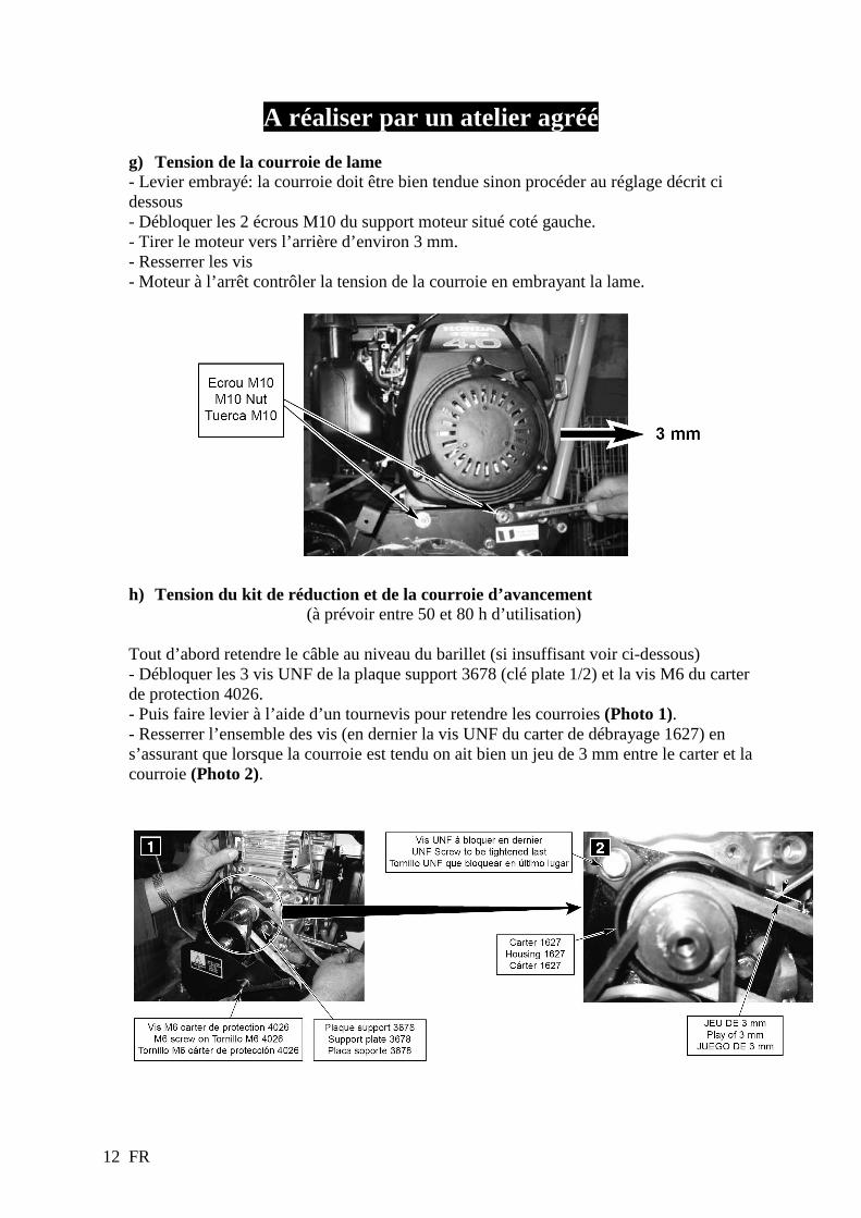
g) Tension de la courroie de lame - Levier embrayé: la courroie doit être bien tendue sinon procéder au réglage décrit ci dessous - Débloquer les 2 écrous M10 du support moteur situé coté gauche. - Tirer le moteur vers l’arrière d’environ 3 mm. - Resserrer les vis - Moteur à l’arrêt contrôler la tension de la courroie en embrayant la lame.
h) Tension du kit de réduction et de la courroie d’avancement (à prévoir entre 50 et 80 h d’utilisation)
Tout d’abord retendre le câble au niveau du barillet (si insuffisant voir ci-dessous) - Débloquer les 3 vis UNF de la plaque support 3678 (clé plate 1/2) et la vis M6 du carter de protection 4026. - Puis faire levier à l’aide d’un tournevis pour retendre les courroies (Photo 1). - Resserrer l’ensemble des vis (en dernier la vis UNF du carter de débrayage 1627) en s’assurant que lorsque la courroie est tendu on ait bien un jeu de 3 mm entre le carter et la courroie (Photo 2).

13 FR
A réaliser par un atelier agréé
i) Réglage du battement de la lame A contrôler en cas de chocs violant. A effectuer lorsque l’on démonte le cardan.
POSITIONNER LE PLATEAU AU POINT NEUTRE:
Tourner le plateau à la main de manière à positionner l’axe du cardan vers le haut
DESSERER LES 2 BOULONS DU CARDAN:
Desserrer les 2 boulons M10 du cardan
POSITIONNER LES SECTIONS DE LA LAME :
En faisant tourner la biellette à l’extrémité (d’un coté ou de l’autre) Faire coulisser la lame de manière à positionner les sections au mieux entre les doigts (égal à un pas). La barre et la machine étant horizontales, dans le mouvement de déplacement de la lame, vérifier qu’une section A occupe au départ une position 1 médiane entre les doigts pour occuper en fin de course une position 2 similaire. En d’autre termes, les positions 1 et 2 correspondent aux positions extrêmes de déplacement de la lame.

14 FR
RESSERER LE CARDAN:
Resserrer très énergiquement les 2 boulons M 10 du cardan
j) Récapitulatif des entretiens courants à éffectuer
Après la première heure d’utilisation Retendre la courroie de lame si nécessaire
Toutes les 60 minutes Maxi Huiler toutes les parties en mouvement: entraîneur, bague, sections etc.
Toutes les 6 à 8 heures Graisser à la pompe le tube de l'arbre oscillant Graisser à la pompe le tube de l'axe porte barre
Graisser à la pompe le cardan Affûter la lame
Régler le jeu de la lame Vérifier la tension de la courroie de lame
Après chaque fauche Nettoyer la barre de coupe
Entre 50 et 80 heures Régler la tension des courroies d'avancement
En cas de chocs Régler le battement de la lame

15 FR
k) Prescription ESM
Montage : Montage et démontage de la lame Porter des gants de protection ! Démontage : 1. Desserrer les serre-vis (a) des supports de lame. 2. Retirer l'étui de protection (b), le cas échéant 3. Ouvrir le support de lame (c) 4. Retirer la lame Montage : 1. Huiler les guides et les surfaces de glissement (huile biodégradable par ex. huile
alimentaire) 2. Placer la lame 3. Refermer le support de lame (a) 4. Régler le support de lame comme décrit au point Entretien : contrôle, réglage et
nettoyage 5. Placer l'étui de protection (b) Attention ! Les barres de coupe doivent pouvoir fonctionner souplement après le serrage des serre-vis ! – Montage : Barre de coupe sur la commande / machine Le montage de la barre de coupe sur la commande est autorisé uniquement sur les points convenus entre ESM et le fabricant de l'outil ! En cas de montage ou de commande différente, le fabricant du produit final est responsable pour la sécurité de montage et de fonctionnement ainsi que pour la mise à disposition de consignes de montage détaillées dans ses instructions d'opération ! Commande latérale / centrale : Le montage de la barre de coupe est décrit ici de façon générale. Pour plus de détails, consulter la notice de montage de l'entraînement concerné : 1. Fixation de l'entraîneur de la lame (si outil livré non pré-monté). 2. Fixation de la barre de coupe sur la commande au moyen des vis fournies (veiller à ce que le pivot d'entraînement se trouve dans la
coulisse de l'entraîneur de la lame) 3. Si possible, vérifier les propriétés de fonctionnement manuellement sans allumer le moteur et, le cas échéant, placer un dispositif de
protection et l'étui de protection de la lame Utilisation conforme Cet équipement doit être utilisé exclusivement pour les travaux de coupe agricoles, forestiers et urbains usuels ainsi que pour l'entretien des paysages extensif. Pour certains cas (cf. instructions d'opération spécifiques), une utilisation en position verticale est également permise. Toute autre utilisation est considérée comme non conforme et le fabricant exclue toute responsabilité vis-à-vis des dommages en résultant. Par ailleurs, cet équipement doit être utilisé uniquement dans le respect des conditions de sécurité, de montage, de démontage, de mise en service, d'utilisation et de maintenance prescrite par les fabricants et les distributeurs ! Utilisez la barre de coupe en veillant à votre sécurité ;
. Pour un levage court (~ 55 mm), n'utilisez jamais la barre de coupe à une vitesse de rotation du moteur de plus de 1100 t/min
. Pour un levage long (~ 85 mm), n'utilisez jamais la barre de coupe à une vitesse de rotation du moteur de plus de 850 t/min Attention ! En raison de sa construction et utilisation spécifiques, tous les dangers potentiels ne peuvent pas être éliminés. Ces risques résiduels sont décrits dans le document ci-joint "Consignes générales de sécurité". Le fait d'éviter ces dangers est de la seule responsabilité de l'utilisateur ! Entretien : contrôle, réglage et nettoyage Les dysfonctionnements provoqués par un entretien insuffisant ou incorrect peuvent conduire à des coûts élevés de réparation et à une longue période d'immobilisation de la barre de coupe. Un contrôle de la capacité de fonctionnement et un entretien régulier sont de ce fait indispensables !!
. Seule des lames aiguisées, bien réglées et affûtées garantissent un fonctionnement sans faille
. Les lames de coupe doivent être toujours droites, les sections et les dos de lame tordus doivent être redressés
. En cas de forte usure de la lame, nous vous recommandons de remplacer la lame
. Les sections endommagées, usées ou présentant du jeu doivent être remplacées
. Les sections doivent s'e placer les unes sur les auctres sans jeu. Dans le cas contraire, les guides doivent être réglés à nouveau ou être changés s'ils sont usés

16 FR
Guide-lame : Lorsque le jeu entre les plaques de guidage (C) et les supports de lame dépasse env. 1,5 mm, lorsqu'une nouvelle lame est montée ou après le desserrage des vis de fixation (2) et (3), un réglage est nécessaire.
Pour le réglage des guide-lames, il est important de régler tout d'abord un guidage correctement puis les suivants. Après le réglage des différents guidages, la lame doit avoir suffisamment de jeu pour pouvoir se déplacer facilement dans les guides. Procéder aux réglages de la façon suivante : 1. Desserrer les vis de fixation (1) des supports de lame. 2. Retirer les vis de fixation (5) et (4) 3. Retirer le support de lame, les équerres (G) et les plaques d'usure (E), les nettoyer et les remonter. 4. Serrer légèrement les vis de fixation (5,4) puis les vis de serrage (1) entre le pouce et l'index. 5. Régler une distance de saillie (4) de 2 mm entre la lame mobile et la lame fixe et la fixer à l'aide de 2 serre-joints (5) ou pince à étau. Attention : Veiller à ce que la distance de saillies des lames soit la même sur toute la longueur de la barre de coupe ! 6. Poser les plaques d'usure (E) sur les plaques de guidage (C). 7. Déplacer les équerres (G) et le support de lame jusqu'à ce que le jeu entre la plaque de guidage (C) et le support de lame soit de 0,2
mm (épaisseur d'une carte postale). 8. Serrer les vis de fixation (4) , (5) et répétez l'opération pour les autres guides dans le même ordre. 9. Appuyer sur le support de lame et serrer simultanément le serre-vis (1) (Md = 50 Nm). Attention ! Après le réglage, la lame doit avoir suffisamment de jeu pour pouvoir se déplacer facilement dans les guides - Réglage de la hauteur de coupe : Le guidage de la hauteur de coupe de la barre de coupe s'effectue à l'aide des supports de glissière montées par celles-ci (b) et des glissière (c). Pour régler / modifier la hauteur de coupe, procéder de la façon suivante : Montage des supports de glissières (b) en tant que glissières. La barre de coupe coupe à ras du sol. Montage de supports de glissières (b) pour le montage des glissières ajustables. La barre de coupe coupe à ras du sol. Montage des glissières ajustables (c). Pour le réglage, desserrer les serre-vis (a) et tourner les glissières (c) dans la position de coupe souhaitée. Barre de coupe : Après chaque coupe, la lame supérieure doit être démontée afin de nettoyer la barre de coupe et notamment l'ensemble des surfaces de guidage et de glissement. Avant le remontage, éliminer les dommages éventuels, redresser les sections tordues, affûter les sections émoussées et huiler les surfaces de guidage et de glissement pour lesquelles cela est nécessaire. En cas de longue période d'inutilisation, démonter la lame et l'entreposer de façon sûre dans un endroit sec.
17 FR
Entraîneur : Veuiller à ce que le jeu entre l'entraîneur de lame et la broche d'entraînement ne soit pas trop important car cela pourrait provoquer la casse du dos de la lame. Pour les entraîneurs ajustables, le jeu doit être réglé à env. 0,1- 0,2 mm à chaque changement de lame. Pour les entraîneurs non ajustables, les pièces concernées doivent être remplacées lorsque le jeu est supérieur à 1 mm. Graisser avec un lubrifiant résistant à la pression. Remplacer immédiatement les pièces endommagées ! Affûtage de la lame : L'affûtage de la lame est très important pour une coupe propre et sans difficultés. Un affûtage correct est décrit en détails dans notre notice Affûtage correct de barres de coupe. Lame supérieure mobile (a) : Selon les conditions d'utilisation, affûter à un angle de 40° toutes les 5 à 20 de fonctionnement. Lame inférieure fixe (b) : Les sections des barres de coupe hobby, Z, universelles et communales sont pourvues d'arêtes à la denture spéciale leur garantissant une très longue durée de vie. Dans de nombreux cas, un affûtage n'est pas nécessaire. Si toutefois, cela était nécessaire, nous vous recommandons d'utiliser une meuleuse d'angle pourvue d'un disque normal. Affûter avec la surface latérale du disque à un angle de 80-90° Attention : Ne pas faire fonctionner les lames à vide car celles-ci s'émoussent plus vite - Remplacement de section unique : Les sections fortement usées ou endommagées peuvent être changées individuellement. Pour un remplacement individuel correct des sections, celui-ci doit être effectué par une entreprise spécialisée ou conformément à notre notice Remplacement individuel correct d'éléments de coupe. Consignes d'entretien et de graissage : Graisser avec un lubrifiant résistant à la pression : en cas d'utilisation de l'outil pour la coupe d'aliments, les endroits entrant en contact avec ces derniers doivent être graissés uniquement au moyen de lubrifiants alimentaires.
Identification et résolution des erreurs : Pour identifier et résoudre les erreurs plus facilement, celles-ci ainsi que leur cause et leur solution sont résumées dans le tableau suivant.
Pièces de rechange : Nous vous recommandons expressément d'utiliser uniquement des pièces de rechange et des accessoires ESM originaux car seuls ces derniers sont contrôlés et agréés par nos soins. Le montage et/ou l'utilisation d'autres produits peut nuire l'action et la sécurité de la machine. Nous excluons toute garantie en cas d'utilisation de pièces de rechange et d'accessoires non originaux. Informations techniques complémentaires : Plus d'informations techniques telles que les listes de pièces de rechange et nos notices sur notre site Internet : www.esm-ept.de. Pour toute question spécifique, veuillez-vous adresser à votre revendeur ou au fabricant.
Contrôle / Consignes d'entretien Heures de fonctionnement / Période toutes les 4 h toutes les 8 h toutes les 5-25 h
Vérifications des guide-lames X Vérifications des lames et de l'entraîneur de lame X Contrôle de la totalité de la barre de coupe : pièces ayant du jeu, endommagées, notamment des composants relatifs à la sécurité.
X
Graissage des entraîneurs de lame X Affûtage de la lame X Nettoyage de la barre de coupe tous les jours
Problème : Cause : Solution : Le produit à couper se met entre la lame supérieure et inférieure
Les lames sont émoussées Les lames ne sont pas droites Les sections ne sont pas alignées
Remplacer ou affûter la lame Démonter la lame et la redresser Redresser les sections
Les sections de la lame inférieure se coincent dans celles de la lame supérieure
La lame supérieure est trop éloignée de la lame inférieure
Régler le guide-lame
Les sections ne se placent pas les unes sur les autres Les sections les lames ou le dos des lames sont tordus
Contrôler que la lame soit droite, la redresser le cas échéant jusqu'à ce que les sections soient alignées Le dos des lames casse
Bras inférieurs tordus
Vitesse de rotation trop élevée Jeu trop important de l'entraîneur Fixation non conforme de l'entraîneur Réglage non conforme des guide-lames
Réduire la vitesse de rotation Vérifier le jeu de tous les éléments pertinents et le corriger le cas échéant Régler correctement le guide-lame

1 EN
INTRODUCTION Dear Customer, We thank you for choosing when purchasing your brush cutter.This manual has been designed to familiarise you with your new machine and enable you to use it in optimum condition and to maintain it. From our constant concern to have you benefit as fully as possible from technological advances, new equipment and materials and our own experience, we are constantly updating our models; For this reason we may alter the characteristics and information contained in this manual without notice and with no requirement to provide an update. The illustrations in this manual show the most representative model for the subject concerned. If you encounter any problems or have any questions regarding the machine, please contact your dealer or an approved retailer. Keep this manual within easy reach so that you can consult it at any time and ensure that the manual is handed over with the machine if you sell it. No reproduction of this publication, in whole or in part, is permitted without prior written authorisation. The attached “part-list” (optional), is destined solely for the approved repairer’s use.
CONTENTS
I. SAFETY PRECAUTIONS ....................................................................................... 2 II. SAFETY LABELS .................................................................................................... 3 III. MACHINE IDENTIFICATION .............................................................................. 4 IV. TECHNICAL INFORMATION .............................................................................. 4 V. PREPARATION ........................................................................................................ 7 VI. USE ............................................................................................................................. 8 VII. TRANSPORT ............................................................................................................ 9 VIII. MAINTENANCE ...................................................................................................... 9

2 EN
I. SAFETY PRECAUTIONS

3 EN
II. SAFETY LABELS You must use your brush cutter with care. To this end, labels have been designed to remind you of the main precautions for use and placed on the machine in the form of pictograms. The relevant meanings are provided below. These labels are considered as an integral part of the machine. If one of them falls off or becomes difficult to read, please contact your dealer to replace it. We also recommend that you read the safety instructions carefully.
1
2
1- Disconnect the spark plug before conducting any maintenance operation 2- Read the user’s manual
Forward clutch control
Blade clutch handle
Throttle control 1- Fast 2- Slow
1 2
Engine brake control
4 EN
III. MACHINE IDENTIFICATION
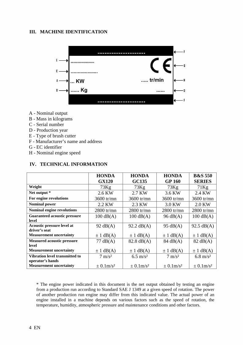
A - Nominal output B - Mass in kilograms C - Serial number D - Production year E - Type of brush cutter F - Manufacturer’s name and address G - EC identifier H - Nominal engine speed IV. TECHNICAL INFORMATION
HONDA
GX120 HONDA GC135
HONDA GP 160
B&S 550 SERIES
Weight 73Kg 73Kg 73Kg 71Kg Net output * 2.6 KW 2.7 KW 3.6 KW 2.4 KW For engine revolutions 3600 tr/mn 3600 tr/mn 3600 tr/mn 3600 tr/mn Nominal power 2.2 KW 2.3 KW 3.0 KW 2.0 KW Nominal engine revolutions 2800 tr/mn 2800 tr/mn 2800 tr/mn 2800 tr/mn Guaranteed acoustic pressure level
100 dB(A) 100 dB(A) 96 dB(A) 100 dB(A)
Acoustic pressure level at driver’s seat
92 dB(A) 92.2 dB(A) 95 dB(A) 92.5 dB(A)
Measurement uncertainty ± 1 dB(A) ± 1 dB(A) ± 1 dB(A) ± 1 dB(A) Measured acoustic pressure level
77 dB(A) 82.8 dB(A) 84 dB(A) 82 dB(A)
Measurement uncertainty ± 1 dB(A) ± 1 dB(A) ± 1 dB(A) ± 1 dB(A) Vibration level transmitted to operator’s hands
7 m/s² 6.5 m/s² 7 m/s² 6.8 m/s²
Measurement uncertainty ± 0.1m/s² ± 0.1m/s² ± 0.1m/s² ± 0.1m/s²
* The engine power indicated in this document is the net output obtained by testing an engine from a production run according to Standard SAE J 1349 at a given speed of rotation. The power of another production run engine may differ from this indicated value. The actual power of an engine installed in a machine depends on various factors such as the speed of rotation, the temperature, humidity, atmospheric pressure and maintenance conditions and other factors.

5 EN
Accessories : For your safety’s sake,it is formally prohibited to fit any other accessory than those specifically designed for your model and type of bruch cutter. ( Listed below ) - Wheels unbreakable KZ04040005- KZ04040006
ADVICE ON USING, MAINTAINING AND ADJUSTING YOUR MOT OR MOWER. 1 - Maximum thickness of cut: 15mm. 2 - Maximum engine speed 2,800 r.p.m. 3 - On slopes, you are advised not to let the machine freewheel backwards or forwards, or to let the clutch out suddenly. This causes a violent shock on the polyamide wheel inside the mechanism which is not covered by the guarantee. 4 - If the drive belt jumps: - Check that the roller is perpendicular and resting on the back of the belt. - Check that tension of the belt is correct 5 - If the traveller breaks: - Engine speed too great. - Inadequate play between the blade and the blade holder - The movement of the blade needs readjusting 6 - When changing the polyamide wheel inside the drive mechanism, ensure it rotates freely on its axis for one turn without straining. If it does not, use a screwdriver to push back the back the bearings from the wheel shaft to relieve the stress between the two cog-wheels.
6 EN
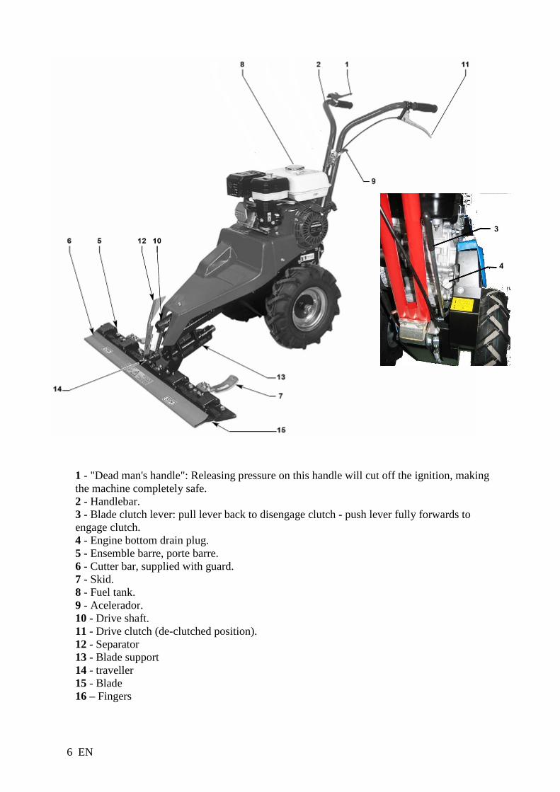
1 - "Dead man's handle": Releasing pressure on this handle will cut off the ignition, making the machine completely safe. 2 - Handlebar. 3 - Blade clutch lever: pull lever back to disengage clutch - push lever fully forwards to engage clutch. 4 - Engine bottom drain plug. 5 - Ensemble barre, porte barre. 6 - Cutter bar, supplied with guard. 7 - Skid. 8 - Fuel tank. 9 - Acelerador. 10 - Drive shaft. 11 - Drive clutch (de-clutched position). 12 - Separator 13 - Blade support 14 - traveller 15 - Blade 16 – Fingers

7 EN
V. PREPARATION WARNING :The engine does not contain oil. a) To fill the fuel tank, start the machine and maintain the engine, see the engine instruction book enclosed with the user manual for the machine. b) Remove the bar support (13) from the front of the machine, attach the cutter bar to it using the four M8 screws fixed to the cutter bar and the part (17). Place the bar support on the bar. Insert the screws from beneath, put on the nuts and tighten hard. It is very important that these 4 nuts and screws are tight. c) Fitting the handlebars: Insert the handlebar stem (1) with the silent-bloc and U-bolt (2) onto the spacer tube. Squeeze the silent-bloc slightly to make it easier to insert the holding rod (3), and insert the pin (4). Hook the clutch transmission (5) onto the handle on the right hand side and the electric cable for the deadman's (6) handle on the left-hand side. To adjust the height of the handlebars, slacken the two bolts (7) which hold the flanges.Swivel the handlebars (1). Re-tighten.
8 EN
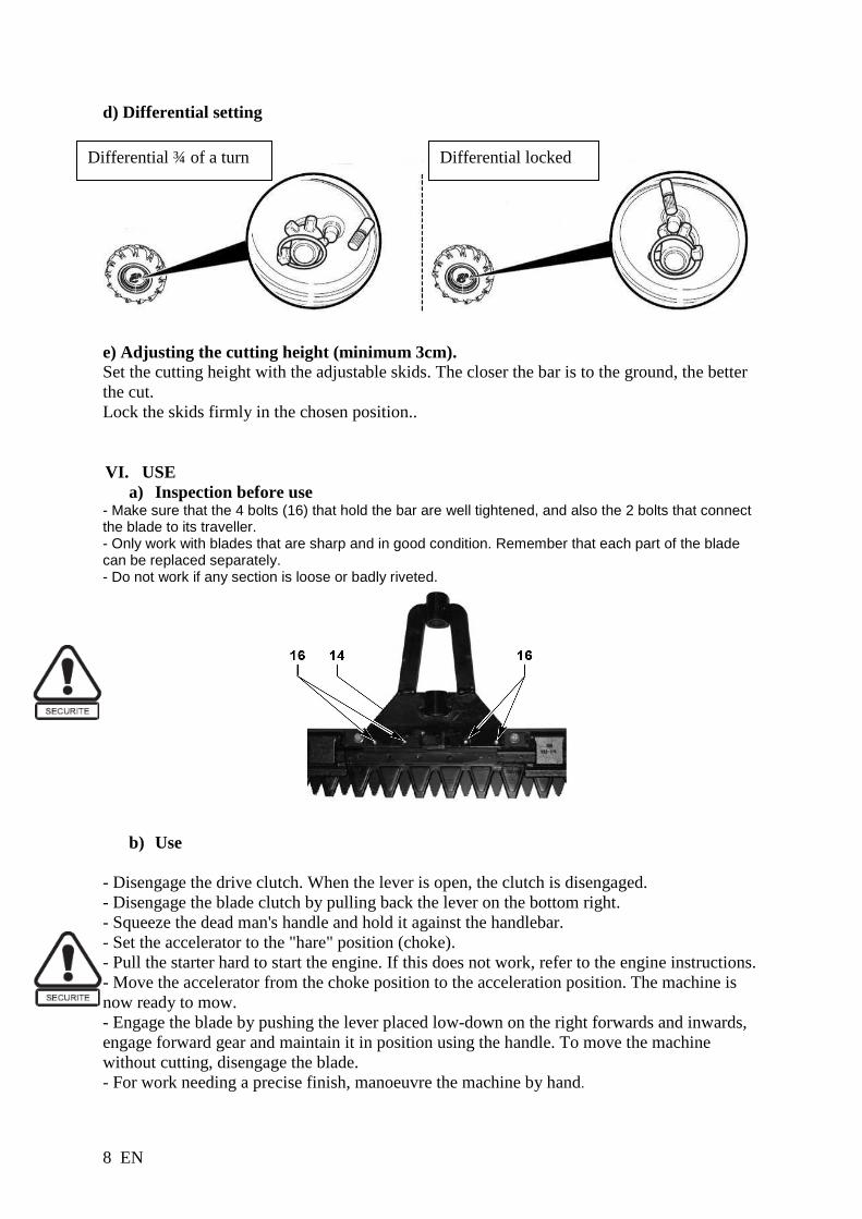
d) Differential setting e) Adjusting the cutting height (minimum 3cm). Set the cutting height with the adjustable skids. The closer the bar is to the ground, the better the cut. Lock the skids firmly in the chosen position.. VI. USE
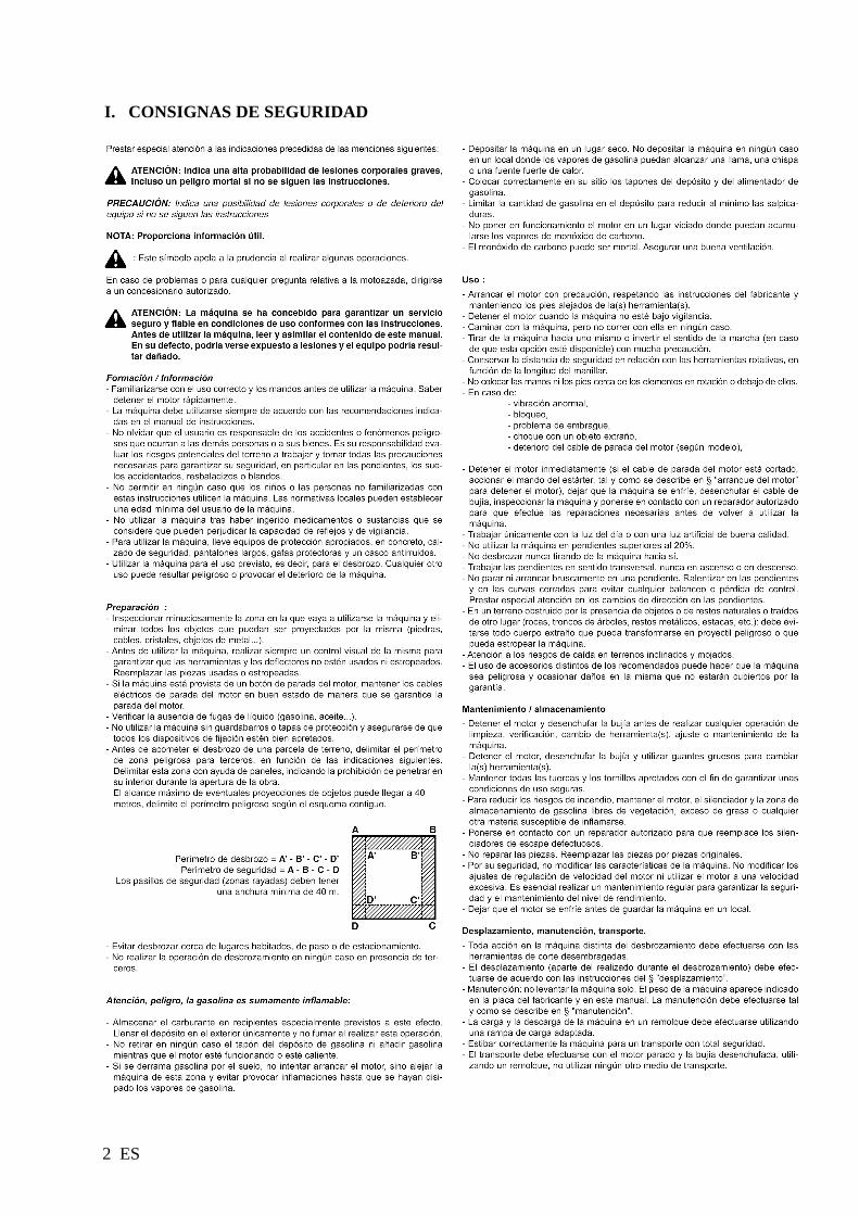
a) Inspection before use - Make sure that the 4 bolts (16) that hold the bar are well tightened, and also the 2 bolts that connect the blade to its traveller. - Only work with blades that are sharp and in good condition. Remember that each part of the blade can be replaced separately. - Do not work if any section is loose or badly riveted.
b) Use
- Disengage the drive clutch. When the lever is open, the clutch is disengaged. - Disengage the blade clutch by pulling back the lever on the bottom right. - Squeeze the dead man's handle and hold it against the handlebar. - Set the accelerator to the "hare" position (choke). - Pull the starter hard to start the engine. If this does not work, refer to the engine instructions. - Move the accelerator from the choke position to the acceleration position. The machine is now ready to mow. - Engage the blade by pushing the lever placed low-down on the right forwards and inwards, engage forward gear and maintain it in position using the handle. To move the machine without cutting, disengage the blade. - For work needing a precise finish, manoeuvre the machine by hand.
Differential ¾ of a turn Differential locked

9 EN
VII. TRANSPORT 1.
2
VIII. MAINTENANCE
a) Lubrication : - Before you begin work, use an oilcan to lubricate all moving parts – the traveller, ring, and sections on both sides of the blade guides. Repeat every 60 minutes max. Every 6 to 8 hours (and at least once a year) use a grease gun to lubricate the tube of the oscillating shaft.and the universal joint. - The engine: see the enclosed instructions. - Oil changes: for easy access to the drain plug, remove the handlebar stem. Protect the belts and the forward drive clutch roller from oil.
b) Routine maintenance. - Before doing any work on the machine, you must turn off the engine. - From time to time, tighten the 2 bolts connecting the blade to its traveller. - Sharpen the blade . - When stopping work for several hours, or at the end of the working day, clean the bar with a water jet; if necessary, remove the blade to clean it thoroughly. Let it dry and oil it. - To maintain the engine, see the instruction book. - The blade guides need adjusting carefully. They should be tight enough to hold the section against the blade, but still let the blade move freely. Check them after every eight hours' work.

10 EN
c) Cleaning the cutter bar : (after each use)
Remove the blade : - Slacken the blade presses with a 17mm spanner - Lift up the blade press - Remove the blade. - Clean the cutter bar, particularly the surfaces that rub together (moving and fixed). - Check the condition of the blade. Make sure the blade strip and the sections are not bent; if necessary straighten them.
Reassemble the blade: - Place the blade in position. - Lower the blade presses making sure they are correctly positioned . - Tighten the screws using a 17mm spanner. - Check the blade moves freely (see paragraph e)
d) Lubrication: - Lubricate the universal joint at the grease nipple - Lubricate the bar support tube at the grease nipple. - Lubricate the drive support tube at the grease nipple. - Lubricate the drive ring. - Oil the blade.

11 EN
e) Adjusting the play of the blade: (Every 6 to 8 hours) - Recommended play between the blade and the blade press 0.1 to 1 mm. - Slacken the two blade press screws with a 13 mm spanner. - Then pull the blade press back and push the wearing plate forwards. - Re-tighten the two screws with a 13 mm spanner. - Do the same for all the blade presses. - Make sure that the blade extends slightly beyond the fingers by 0.5 to 2.5 mm. - Once all the blade presses are tightened, the blade must be able to slide freely.
f) Sharpening the blade (Every 6 to 8 hours) Hold the blade firmly in a vice. Either: -With an angle-grinder: (protective goggles recommended) Sharpen both angles on each section. Leaning the grinder to suit the angle of the cutting edge
Or : - With a file: Sharpen both angles on each section, leaning the file to suit the angle of the cutting edge.

12 EN
To be performed by an approved workshop
g) Tensioning the blade belt - Clutch lever: the belt must be under tension. If it is not, adjust as described below. - Loosen the two M10 nuts from the engine support situated on the left. - Pull the engine backwards about 3 mm. - Re-tighten the screw - With the engine stopped, check the tension of the belt by engaging the blade.
h) Tensioning the reduction kit and the drive belt (Schedule between 50 and 80 hours of use)
Firstly pull the cable taut at the barrel (if not long enough see below). - Loosen the three UNF screws on the support plate 3678 (flat 1/2" spanner) and the M6 screw from the protective housing 4026. - Then use a screwdriver as a lever to tighten the belts (Photo 1). - Re-tighten all the screws (tightening the UNF screw on the gear housing 1627 last). Ensure that when the belt is tight that there is a play of 3 mm between the housing and the belt (Photo 2).

13 EN
To be performed by an approved workshop
i) Adjusting the travel of the blade Check after any violent shocks. Adjust when you dismantle the universal joint.
POSITIONING THE PLATE AT DEAD CENTRE:
Turn the plate by hand until the axis of the universal joint is at the top
SLACKENING THE 2 BOLTS OF THE UNIVERSAL JOINT:
Slacken the two M10 bolts of the universal joint
POSITIONING THE SECTIONS OF THE BLADE:
By turning the rocker bar at the end (one side or the other), slide the blade so that the cutting sections are positioned part-way between the fingers,(equal to one step). - With the bar and the machine horizontal, when altering the position of the blade, check that a section A initially occupies a median position 1 between your fingers in order to occupy a similar position 2 at the limit switch. In other words, positions 1 and 2 correspond to the extreme positions for moving the blade.

14 EN
RE-TIGHTENING THE UNIVERSAL JOINT:
Tighten the two M10 bolts of the universal joint very firmly
j) Summary of running maintenance to be performed
After the first hour of use Retighten the blade belt, if required
At least every 60 minutes Oil all the moving parts: coupling disk, rings, sections, etc
Every 6 to 8 hours Lubricate the oscillating shaft’s tube with a grease gun Lubricate the bar support shaft’s tube with a grease gun
Lubricate the universal joint with a grease gun Sharpen the blade
Adjust the blade’s play Check the tension of the blade’s belt
After each mowing Clean the cutting bar
Between 50 and 80 hours Adjust the drive belt’s tension
In the event of an impact Adjust the beating of the blade

15 EN
k) ESM prescription
Assembly: Removal and Installation of the Knives Wear protective gloves!! Removal:
1. Loosen the clamp bolt (a) of the knife holder. 2. Remove knife protection strip, if fitted 3. Open up the knife holder (c) 4. Remove the knife
Installation: 1. Lubricate the guides and slide faces (with bio-degradable oil, e.g. edible oil) 2. Insert the knife 3. Close the knife holder (a) 4. Adjust knife guides (a) as described in; Maintenance: Inspection, Adjustment
and Cleaning 5. Attach knife protection strip (b) Attention! After the adjustment the knife must move freely back and forth in the guides- Assembly: Cutterbar to Drive/Machine The assembly of the cutterbar is only permitted at points agreed between ESM and the respective device manufacturer. Should the installation respectively the drive deviate, then the manufacturer of the completed machinery is responsible for the assembly and operational safety as well as for the provision of comprehensive assembly instructions in his operating manual! Side-/Central drive: Assembly of the Cutterbar is described briefly in the following. The assembly instructions for the respective cutter drive specify the detailed procedure:
1. Attachment of the knife head (if not already factory-assembled). 2. Attachment of the cutterbar to the cutter drive using the screws provided (it must be ensured that the connecting bolt encroaches
into the knife head). 3. When possible, manually check the function of the implement without a mechanical drive at first and if required, assemble the
safety equipment and knife protection strip Intended Use: This equipment may only be used for standard agricultural, forestry and municipal mowing, as well as for extensive landscape cutting operations. In special cases (refer to the specific operating instructions) operation of the equipment is also allowed when it is in a vertical position. Any use other than the intended is not permitted and the manufacturer accepts no liability for any damages which may thereby be incurred. The Intended use also includes the adherence to all safety, assembly, disassembly, commissioning, operation and servicing specifications of the manufacturer and the distributors. For your own safety, never operate the cutterbar;
. at a rotational speed higher than 1100 rpm (on a short stroked cutterbar (~ 55 mm))
. at a rotational speed higher than 850 rpm (on a long stroked cutterbar (~ 85 mm)) Attention! Due to its functional design, all potential risks cannot be eliminated. The attached document "General Safety Instructions" makes reference to these residual risks, for the avoidance of which the operator bears the full responsibility! Maintenance: Inspection, Adjustment and Cleaning Operational breakdowns caused by inadequate or improper maintenance may lead to high repair costs and long downtimes of the cutterbar. Regular inspections and maintenance to assure operational reliability is therefore essential!!
. Only sharp, well adjusted and ground knives work trouble free
. The mowing knives must always be straight, bent knife sections and knife backs must be straightened
. If there is heavy wear-off or damage to the knife, we recommend replacing the knife
. Damaged, loose or worn out knife sections need to be replaced
. Knife sections must lie on top of one another without any free-play between them. Should this not be the case, the knife guides must be readjusted or need to be replaced due to heavy wear down.

16 EN
Knife guide: When free-play between the guide plates (C) and the knife holders has reached 1.5 mm or a new knife has been fitted and every time after the fasteners have been loosened, a basic readjustment is required.
Important for the readjustment of the knife guides is to first correctly adjust a single guide and then work on the following ones. After the adjustment of each individual guide the knife must move freely. Adjustments are carried out as follows: 1. Loosen the clamp bolt (1) of the knife holder. 2. Unscrew the mounting screws (5) and (4) 3. Remove and clean the knife holder with angles (G) as well as friction plates (E) then re-assemble it. 4. Slightly tighten the mounting screws (5, 4) and then the clamp screws (1) with thumb and forefinger. 5. Set a protrusion of 2 mm between the movable and the stationary knife and secure it with 2 clamps or vice grips. Attention: It is important to ensure that "knife pr otrusion" is equal over the whole length of the cutterbar - 6. Bring the friction plates (E) in contact with the guide plates (C). 7. Move the angle (G) and the knife holder until a free-play between the guide plate (C) and the knife holder of 0.2 mm (post card
thickness) remains. 8. Tighten the mounting screws (4), (5), repeat this procedure for the remaining guides in the same sequence. 9. Press don on the knife holder and, at the same time, tighten the clamp bolt (1) (Md = 50 Nm). Attention! After the adjustment the knife must move freely back and forth in the guides- Adjusting the cutting height The cutting height of the cutterbar is set through the skid mount (b) and the gliding skids (c) attached to the cutterbar. An adjustment to the cutting height is carried out as follows: Skid mount (b) attached as skid. The cutterbar cuts close to the ground. Skid mount (b) attached for mounting of gliding skid(c). The cutterbar cuts close to the ground. Gliding skid(c) attached. For adjustment, loosen the clamp bolt (a) and turn the gliding skid (c) into the desired cutting height position. Cutterbar: After every cutting operation, the top knife has to be removed to assure proper cleaning of the cutterbar and all the relevant guiding and friction surfaces. Before the reassembly of the knife, check and repair damaged parts, straighten bent knisections, sharpen blunt sections and apply lubrication to all relevant guide and frictions surfaces. If no cutting work is to be done for an extended period, remove knife and m

17 EN
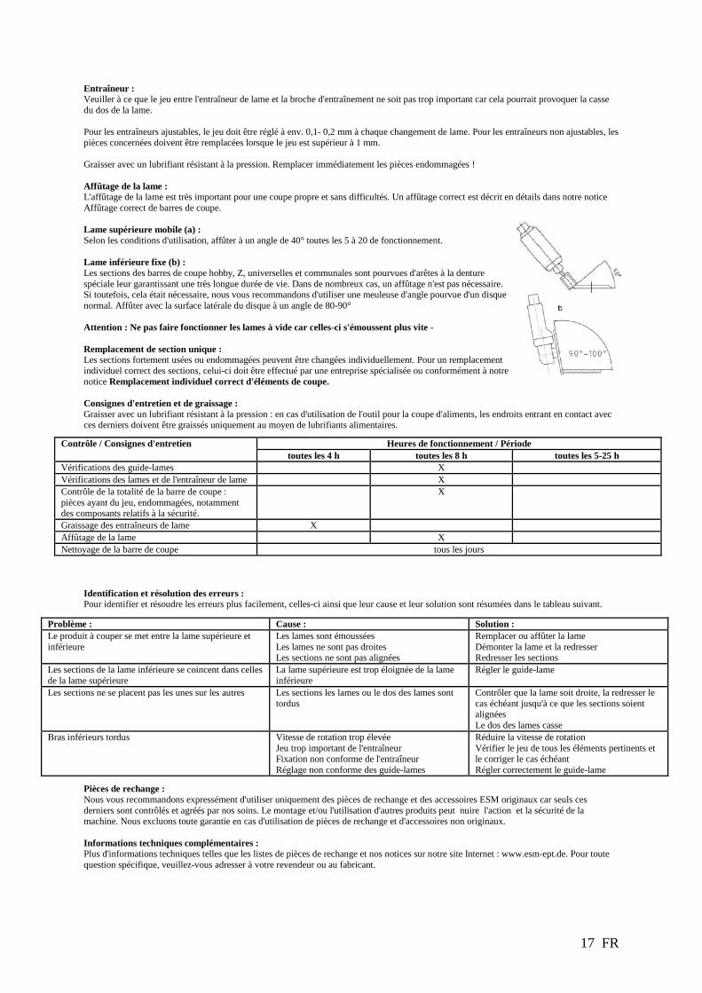
Knife Head: Please ensure that there is no excessive free-play between the knife head and the drive element, as too much free-play may cause the knife back to break. In case of adjustable knife heads, the free-play should be readjusted, after every knife change, to approx. 0.1- 0.2 mm. For non-adjustable knife heads, the appropriate parts have to be replaced if the free-play is greater than 1 mm. Lubrication should be done with compression-proof grease only! Damaged parts are to be exchanged immediately! Sharpening of Knives: The proper sharpening of the knives is of great importance for clean and trouble-free mowing. The proper sharpening procedure for the knives is described in detail in our guideline: Professional Sharpening of Knives. Driven top knife (a): Subject to the operating conditions, sharpen the cutting edges at an angle of 40 degrees after every 5-20 operating hours. Stationary bottom knife (b): The bottom knife sections of Hobby, Z, Universal and Municipal Cutterbars have a special serration at the cutting edge, through which they gain a very long service life and in fact, in many cases regrinding can be avoided completely. Should regrinding nonetheless be required, we recommend an angle grinder fitted with a standard grinding disc. Regrinding is to be done with the side surfaces of the grinding disc at an angle of 90-100°. Attention: Do not let the cutting edges overheat, or they will loose their temper and therefore blunt much quicker - Replacing Single Knife Sections: Heavily worn or damaged knife sections can be replaced individually. The replacement of individual sections should be carried out by a specialist and/or according to our instructions; Proper Replacement of Individual Knife Sections.
Maintenance and Lubrication Instructions: Lubrication should be done with compression-proof grease only: If the implement is being used for cutting eatables, all lubricated parts coming in contact with the material to be cut, must be lubricated with food grade lubricants only!
Trouble-shooting and Remedy: For quick and easy problem identification, the following table provides a list of the most common problems, its related cause and the remedy needed. Spare Parts: We would like to bring to your attention that only ESM original spare parts and accessories should be used, as only these have been tested and approved by us. The fitting and/or use of other products may compromise the function and the safety of the machine. We accept no warranty and liability for damages resulting from the use of other than original spare parts and accessories. Additional Technical Information Further technical information, such as spare parts lists and user manuals are to be found on our Website: www.esm-ept.de. For specific questions please make contact directly with your dealer or the manufacturer.
Maintenance instructions Every 4 h Every 8 h Every 5-25 h Checking of the knife guide X Checking of the knives and the knife head X Check the entire cutterbar for loose and damaged parts, especially components relevant to safety.
X
Grease knife head bearing X Sharpen the knives X Cleaning of the Cutterbar daily
Problem Cause Remedy Cut material becomes stuck between the top and bottom knife
Knives are blunt Knives are not straight Knife Sections are not aligned
Replace or sharpen knives Remove and straighten knives Straighten knife sections
Section tips of the bottom knife work themselves into the sections of the top knife.
Top knife protrudes too far over the bottom knife
Readjust the knife guides
Knife sections are not lying flat on top of each other Knife sections or knife buckled, Knife back distorted Knife guides incorrectly adjusted
Check the straightness of the knives, if necessary, straighten until the knife sections are all aligned Readjust the knife guides
Knife backs break
Excessive rotational speed Excessive play in the knife head Improperly attached knife head Improper adjustment of the knife guides
Reduce rotational speed Check free-play in all relevant parts and eliminate if necessary Readjust the knife guides


1 ES
INTRODUCCIÓN Estimado/a usuario/a: Acaba de adquirir una desbrozadora y le agradecemos su confianza.Hemos redactado este manual con el objetivo de que se familiarice con su nueva máquina y para permitirle utilizarla en las mejores condiciones y efectuar su mantenimiento. Con el interés de que pueda aprovechar al máximo las evoluciones tecnológicas, los nuevos equipos o materiales y nuestra experiencia, los modelos se mejoran con regularidad; por este motivo, la información y las características contenidas en este manual pueden modificarse sin previo aviso y no estaremos obligados a su actualización. Las ilustraciones de este manual muestran el modelo más representativo en relación con el tema tratado. En caso de que tenga cualquier problema o cualquier pregunta relativa a la máquina, diríjase a su concesionario o a un distribuidor autorizado. Conserve este manual al alcance de la mano para consultarlo en cualquier momento y asegúrese de que acompañe a la máquina en caso de reventa. No está permitida la reproducción, ni siquiera parcial, de la presente publicación, sin autorización previa por escrito. La lista adjunta de piezas (opcional) está destinada únicamente al reparador autorizado.
ÍNDICE
I. CONSIGNAS DE SEGURIDAD........................................................................... 2 II. ETIQUETAS DE SEGURIDAD ........................................................................... 3 III. IDENTIFICACIÓN DE LA MÁQUINA ............................................................. 4 IV. DATOS TECNICOS .............................................................................................. 4 V. PREPARACIÓN: ................................................................................................... 7 VI. UTILIZACION ....................................................................................................... 8 VII. MANUTENCION ................................................................................................... 9 VIII. MANTENIMIENTO .............................................................................................. 9
2 ES
I. CONSIGNAS DE SEGURIDAD

3 ES
II. ETIQUETAS DE SEGURIDAD Debe utilizar la desbrozadora con prudencia. Con esta finalidad, se han colocado etiquetas en la máquina en forma de pictogramas destinadas a recordarle las principales precauciones de uso. A continuación se proporciona su significado. Estas etiquetas se consideran parte integrante de la máquina. Si alguna de ellas se despega o resulta difícil de leer, póngase en contacto con su concesionario para reemplazarla. Le recomendamos igualmente que lea las consignas de seguridad con atención.
1
2
1- Desconectar la bujía antes de realizar cualquier operación de mantenimiento o reparación. 2- Lea el manual de uso.
Mando de embrague de avance
Empuñadura de embrague cuchilla
Mando de gas 1- Rapido 2- Lento
1 2
Mando de freno motor

4 ES
III. IDENTIFICACIÓN DE LA MÁQUINA
A - Potencia nominal B - Masa en kilogramos C - Número de serie D - Año de fabricación E - Tipo de desbrozadora F - Nombre y dirección del fabricante G - Identificación CE H - Velocidad nominal del motor
IV. DATOS TECNICOS HONDA
GX120 HONDA GC135
HONDA GP 160
B&S 550 SERIES
Peso 73Kg 73Kg 73Kg 71Kg Potencia neta* 2.6 KW 2.7 KW 3.6 KW 2.4 KW para un régimen motor 3600 tr/mn 3600 tr/mn 3600 tr/mn 3600 tr/mn Potencia nominal 2.2 KW 2.3 KW 3.0 KW 2.0 KW Régimen motor nominal 2800 tr/mn 2800 tr/mn 2800 tr/mn 2800 tr/mn Nivel de potencia acústica garantizada
100 dB(A) 100 dB(A) 96 dB(A) 100 dB(A)
Nivel de presión acústica en el puesto de conducción
92 dB(A) 92.2 dB(A) 95 dB(A) 92.5 dB(A)
Incerteza de medida ± 1 dB(A) ± 1 dB(A) ± 1 dB(A) ± 1 dB(A) Nivel de potencia acústica medida
77 dB(A) 82.8 dB(A) 84 dB(A) 82 dB(A)
Incerteza de medida ± 1 dB(A) ± 1 dB(A) ± 1 dB(A) ± 1 dB(A) Nivel de vibraciones en las manos del operario
7 m/s² 6.5 m/s² 7 m/s² 6.8 m/s²
Incerteza de medida ± 0.1m/s² ± 0.1m/s² ± 0.1m/s² ± 0.1m/s²
* La potencia del motor indicada en este documento es una potencia neta obtenida por la prueba de un motor de serie según la norma SAE J 1349 a una velocidad de rotación dada. La potencia de otro motor de producción puede ser diferente de este valor indicado. La potencia real de un motor instalado en una máquina dependerá de diferentes factores, como la velocidad de rotación, las condiciones de temperatura, humedad, presión atmosférica, mantenimiento y demás.

5 ES
Accesorios : Por su seguridad,está terminantemente prohibido montarcualquier otro accesorio distinto de los concebidos especícamente para su modelo y tipo de desbrozadora, que se enumeran en la lista por debajo de. - Ruedas irrompible KZ04040005- KZ04040006
ALGUNOS CONSEJOS DE UTILIZACIÓN, DE MANTENIMIENTO Y DE AJUSTE DE SU MOTOSEGADORA. 1 - Sección máxima que cortar: 15 mm. 2 - Ajuste velocidad motor máximo: 2800 rev/minuto. 3 - En las cuestas, se desaconseja dejar bajar la máquina en rueda libre (hacia atrás o hacia delante) y volver a embragar brutalmente, podría provocar así un choque violento sobre la rueda poliamida en el interior del mecanismo (deterioro no cubierto por la garantía). 4 - En caso de salto de la correa de avance: - Verificar la correcta perpendicularidad del rodillo apoyado en relación con el dorso de la correa. - Verificar la tensión de esta correa (Ver capítulo A). 5 - En caso de rotura del arrastrador: - Régimen motor demasiado importante. - Falta de juego entre la cuchilla y el portacuchilla (Ver capítulo B párrafo 3). - Ajuste incorrecto del movimiento lateral en relación con la articulación Cardán y el excéntrico (Ver capítulo C). 6 - Durante el cambio de la rueda poliamida en el mecanismo de arrastre, procurar efectuar 1 rotación libre (sin esfuerzo) al nivel del árbol de rueda, sino, mediante un destornillador, empujar los cojinetes lado árbol de rueda para liberar las tensiones entre los 2 piñones.

6 ES
1 - Empuñadura “hombre muerto”: el más mínimo relajamiento de esta empuñadura asegura la seguridad máxima al cortar el encendido motor. 2 - Esteva. 3 - Desembrague de cuchilla: Palanca tirada hacia atrás: posición desembragada. Palanca empujada hacia delante: posición embragada. 4 - Vaciado sobre bajo motor. 5 - Conjunto barra, portabarra. 6 - Barra de corte, Entregada con su protector. 7 - Patín. 8 - Depósito de gasolina. 9 - Accelerator. 10 - Árbol de arrastre. 11 - Embrague de avance (posición desembragada). 12 - Separador 13 - Porta cuchillas 14 - Arrastrador 15 - Cuchilla 16 – Dedos
7 ES
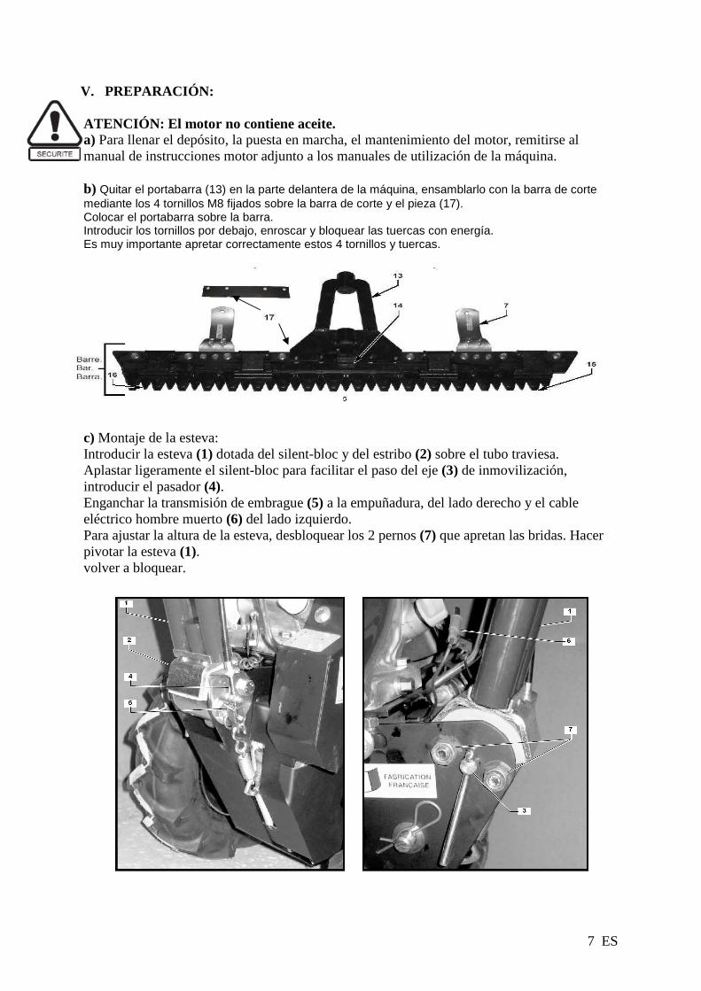
V. PREPARACIÓN: ATENCIÓN: El motor no contiene aceite. a) Para llenar el depósito, la puesta en marcha, el mantenimiento del motor, remitirse al manual de instrucciones motor adjunto a los manuales de utilización de la máquina. b) Quitar el portabarra (13) en la parte delantera de la máquina, ensamblarlo con la barra de corte mediante los 4 tornillos M8 fijados sobre la barra de corte y el pieza (17). Colocar el portabarra sobre la barra. Introducir los tornillos por debajo, enroscar y bloquear las tuercas con energía. Es muy importante apretar correctamente estos 4 tornillos y tuercas. c) Montaje de la esteva: Introducir la esteva (1) dotada del silent-bloc y del estribo (2) sobre el tubo traviesa. Aplastar ligeramente el silent-bloc para facilitar el paso del eje (3) de inmovilización, introducir el pasador (4). Enganchar la transmisión de embrague (5) a la empuñadura, del lado derecho y el cable eléctrico hombre muerto (6) del lado izquierdo. Para ajustar la altura de la esteva, desbloquear los 2 pernos (7) que apretan las bridas. Hacer pivotar la esteva (1). volver a bloquear.

8 ES
d) Ajuste de diferencial e) Ajuste altura de corte (minimo 3 cm). Ajustar la altura de corte mediante los patines orientables. El corte resulta aún mejor cuando la barra está cerca del suelo. Bloquear correctamente los patines en la posición elegida..
VI. UTILIZACION a) Control antes de utilización
- Asegurarse de que los 4 pernos (16)que mantienen la barra estén bien bloqueados, así como los 2 pernos que unen la cuchilla a su arrastrador. - Segar únicamente con una cuchilla en buen estado y bien afilada. Le recordamos que cada sección de cuchilla puede reemplazarse por separado. - No trabajar con una sección mal remachada y que se mueve.
b) Utilización
- Desembragar el avance de la máquina. La empuñadura de embrague está en posición abierta cuando la máquina está desembragada. - Desembragar la cuchilla tirando hacia atrás la palanca del lado derecho abajo. - Mantener la empuñadura “hombre muerto” contra la esteva. - Poner el acelerador en posición liebre (starter). - Tirar del piñón para obtener el arranque (si no consigue arrancar, ver el manual motor). - Dejar la posición starter y colocarse en posisión acelerador. La máquina está lista para segar. - Embragar la cuchilla empujando hacia delante la palanca del lado abajo a la derecha, embragar el avance y mantenerlo en posición mediante la empuñadura. Para los desplazamientos en vacío, desembragar a cuchilla. - Para los trabajos de acabado delicados, maniobrar la motosegadora manualmente.
Diferencial ¾ de vuelta Diferencial bloqueado

9 ES
VII. MANUTENCION
1.
2
VIII. MANTENIMIENTO
a) Engrase: - Antes de empezar, y cada 60 minutos max, ha de engrasar, mediante una aceitera, las partes en movimiento: arrastrador, anillo, secciones de cada lado de los guías de cuchillas. Cada 6 a 8 horas, engrasar mediante una bomba el tubo del árbol oscilante (mínimo una vez al año). - Motor: remitirse al manual adjunto. - Vaciado motor: para facilitar el acceso del tapón de vaciado, quitar la estiva, proteger el rodillo de embrague así como las correas
b) Mantenimiento en curso de funcionamiento. - Antes de cualquier intervención sobre la máquina, cortar imperativamente el motor. - Apretar de vez en cuando los 2 pernos que unen la cuchilla a su arrastrador. - Afilar la cuchilla. - Antes de una parada prolongada de varias horas, o al final del día, limpiar con un chorro de agua la barra, la cuchilla y, si necesario, sacar la cuchilla para limpiarla. Dejar secar. Aceitar. - Para el mantenimiento de su motor, remitirse al manual de instrucciones. - El ajuste de los guías de cuchillas es muy delicado. Ha de ser suficiente para bloquear la sección dejando movilidad a la cuchilla. Verificar cada 8 horas de marcha.
10 ES
c) Limpeza de la barra (tras cada siega)
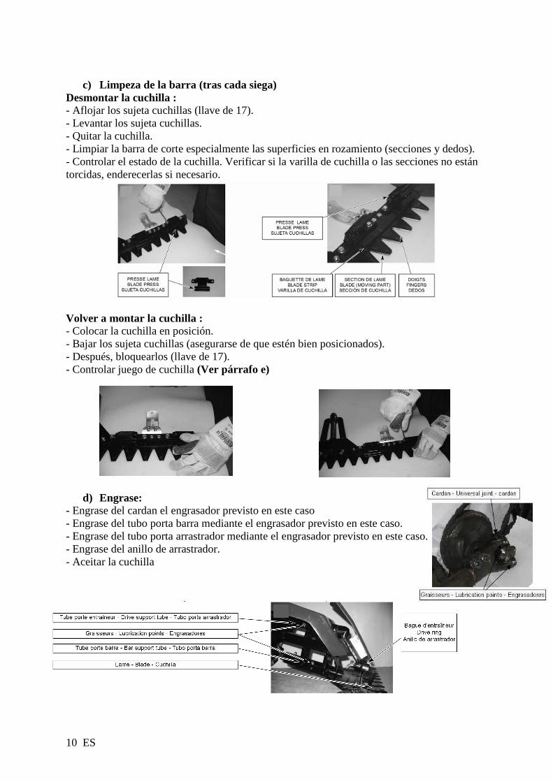
Desmontar la cuchilla : - Aflojar los sujeta cuchillas (llave de 17). - Levantar los sujeta cuchillas. - Quitar la cuchilla. - Limpiar la barra de corte especialmente las superficies en rozamiento (secciones y dedos). - Controlar el estado de la cuchilla. Verificar si la varilla de cuchilla o las secciones no están torcidas, enderecerlas si necesario.
Volver a montar la cuchilla : - Colocar la cuchilla en posición. - Bajar los sujeta cuchillas (asegurarse de que estén bien posicionados). - Después, bloquearlos (llave de 17). - Controlar juego de cuchilla (Ver párrafo e)
d) Engrase: - Engrase del cardan el engrasador previsto en este caso - Engrase del tubo porta barra mediante el engrasador previsto en este caso. - Engrase del tubo porta arrastrador mediante el engrasador previsto en este caso. - Engrase del anillo de arrastrador. - Aceitar la cuchilla

11 ES
e) Ajuste del juego de la cuchilla (cada 6 a 8 h) - Juego aconsejado entre la cuchilla y el sujeta cuchillas 0.1 a 1 mm. - Aflojar los 2 tornillos del sujeta cuchillas (llave de 13). - Después, tirar del sujeta cuchilla hacia atrás y empujar la placa de desgaste hacia delante. - Apretar los 2 tornillos (llave de 13). - Repetir la operación para todos los sujeta cuchillas. - Asegurarse de que la cuchilla sobrepasa ligeramente por encima de los dedos de 0.5 a 2.5 mm. - Tras haber apretado todos los sujetas cuchilla, la cuchilla debe poder deslizar libremente.
f) Afilado de la cuchilla (Cada 6 a 8 h) Mantenerla bloqueada en un tornillo de banco. Es decir : - Con una esmeriladora : (se recomienda llevar gafas de protección) Afilar los 2 ángulos de cada sección. Inclinar la esmeriladora para respetar el ángulo de corte.
Ou : - Con una lima: Afilar los 2 ángulos de cada sección, inclinar la lima para respetar el ángulo de corte.

12 ES
A realizar por un taller autorizado
g) Tensión de las correas de cuchilla - Palanca embragada: la correa ha de ser bien tendida sino proceder al ajuste descrito a continuación - Desbloquear las 2 tuercas M10 del soporte motor situado del lado izquierdo. - Tirar del motor hacia atrás de aproximadamente 3 mm. - Apretar los tornillos - Motor parado, controlar la tensión de la correa embragando la cuchilla.
h) Tensión del kit de reductión y de la correa de avance (Prever entre 50 y 80 h de utilización)
Primero, tensar el cable al nivel del barrilete (si insuficiente ver a continuación) - Desbloquear los 3 tornillos UNF de la placa soporte 3678 (llave plana 1/2) y el tornillo M6 del cárter de protección 4026. - Después, levantar mediante un destornillador para volver a tensar las correas (Foto 1). - Apretar todos los tornillos (acabar por el tornillo UNF del cárter de desembrague 1627) asegurándose de que tras tensar la correa, se obtiene un juego de 3 mm entre el cárter y la correa (Foto 2).

13 ES
A realizar por un taller autorizado
i) Ajuste del batido de la cuchilla Controlar en caso de choques violentos.Efectuar al desmontar el cardán. POSICIONAR EL PLATO EN EL PUNTO NEUTRO:
Girar el plato manualmente de manera a posicionar el eje del cardán hacia arriba.
AFLOJAR LOS 2 PERNOS DEL CARDÁN:
Aflojar los 2 pernos M10 del cardán
POSICIONAR LAS SECCIONES DE LA CUCHILLA:
Al girar el vástago en la extremidad (de un lado o de otro) Deslizar la cuchilla para posicionar las secciones lo mejor posible entre los dedos (igual a un paso). - La barra y la máquina siendo horizontales, en el movimiento de desplazamiento de la cuchilla, verificar que una sección A ocupa al principio una posición 1 mediana entre los dedos para ocupar, en fin de carrera, una posición 2 similar. En otros términos, las posiciones 1 y 2 corresponden a las posiciones extremas de desplazamiento de la cuchilla.

14 ES
APRETAR EL CARDÁN:
Apretar muy fuerte los 2 pernos M 10 del cardán
j) Recapitulativo de los mantenimientos corrientes que efectuar
Tras la primera hora de utilización Tensar la correa de la cuchilla si necesario
Cada 60 minutos como máximo Aceitar todas las partes en movimiento : arrastrador, anillo, secciones etc
Cada 6 a 8 horas Engrasar en la bomba el tubo del árbol oscilante Engrasar en la bomba el tubo del eje portabarra
Engrasar en la bomba el cardan Afilar la cuchilla
Ajustar el juego de la cuchilla Verificar la tensión de la correa de cuchilla
Tras cada sega Limpiar la barra de corte
Entre 50 y 80 horas Ajustar la tensión de las correas de avance
En caso de choques Ajuste del batido de la cuchilla

15 ES
k) Prescripción ESM
Assembly: Removal and Installation of the Knives Wear protective gloves!! Removal:
5. Loosen the clamp bolt (a) of the knife holder. 6. Remove knife protection strip, if fitted 7. Open up the knife holder (c) 8. Remove the knife
Installation: 6. Lubricate the guides and slide faces (with bio-degradable oil, e.g. edible oil) 7. Insert the knife 8. Close the knife holder (a) 9. Adjust knife guides (a) as described in; Maintenance: Inspection, Adjustment
and Cleaning 10. Attach knife protection strip (b) Attention! After the adjustment the knife must move freely back and forth in the guides- Assembly: Cutterbar to Drive/Machine The assembly of the cutterbar is only permitted at points agreed between ESM and the respective device manufacturer. Should the installation respectively the drive deviate, then the manufacturer of the completed machinery is responsible for the assembly and operational safety as well as for the provision of comprehensive assembly instructions in his operating manual! Side-/Central drive: Assembly of the Cutterbar is described briefly in the following. The assembly instructions for the respective cutter drive specify the detailed procedure:
4. Attachment of the knife head (if not already factory-assembled). 5. Attachment of the cutterbar to the cutter drive using the screws provided (it must be ensured that the connecting bolt encroaches
into the knife head). 6. When possible, manually check the function of the implement without a mechanical drive at first and if required, assemble the
safety equipment and knife protection strip Intended Use: This equipment may only be used for standard agricultural, forestry and municipal mowing, as well as for extensive landscape cutting operations. In special cases (refer to the specific operating instructions) operation of the equipment is also allowed when it is in a vertical position. Any use other than the intended is not permitted and the manufacturer accepts no liability for any damages which may thereby be incurred. The Intended use also includes the adherence to all safety, assembly, disassembly, commissioning, operation and servicing specifications of the manufacturer and the distributors. For your own safety, never operate the cutterbar;
. at a rotational speed higher than 1100 rpm (on a short stroked cutterbar (~ 55 mm))
. at a rotational speed higher than 850 rpm (on a long stroked cutterbar (~ 85 mm)) Attention! Due to its functional design, all potential risks cannot be eliminated. The attached document "General Safety Instructions" makes reference to these residual risks, for the avoidance of which the operator bears the full responsibility! Maintenance: Inspection, Adjustment and Cleaning Operational breakdowns caused by inadequate or improper maintenance may lead to high repair costs and long downtimes of the cutterbar. Regular inspections and maintenance to assure operational reliability is therefore essential!!
. Only sharp, well adjusted and ground knives work trouble free
. The mowing knives must always be straight, bent knife sections and knife backs must be straightened
. If there is heavy wear-off or damage to the knife, we recommend replacing the knife
. Damaged, loose or worn out knife sections need to be replaced
. Knife sections must lie on top of one another without any free-play between them. Should this not be the case, the knife guides must be readjusted or need to be replaced due to heavy wear down.

16 ES
Knife guide: When free-play between the guide plates (C) and the knife holders has reached 1.5 mm or a new knife has been fitted and every time after the fasteners have been loosened, a basic readjustment is required.
Important for the readjustment of the knife guides is to first correctly adjust a single guide and then work on the following ones. After the adjustment of each individual guide the knife must move freely. Adjustments are carried out as follows: 10. Loosen the clamp bolt (1) of the knife holder. 11. Unscrew the mounting screws (5) and (4) 12. Remove and clean the knife holder with angles (G) as well as friction plates (E) then re-assemble it. 13. Slightly tighten the mounting screws (5, 4) and then the clamp screws (1) with thumb and forefinger. 14. Set a protrusion of 2 mm between the movable and the stationary knife and secure it with 2 clamps or vice grips. Attention: It is important to ensure that "knife pr otrusion" is equal over the whole length of the cutterbar - 15. Bring the friction plates (E) in contact with the guide plates (C). 16. Move the angle (G) and the knife holder until a free-play between the guide plate (C) and the knife holder of 0.2 mm (post card
thickness) remains. 17. Tighten the mounting screws (4), (5), repeat this procedure for the remaining guides in the same sequence. 18. Press don on the knife holder and, at the same time, tighten the clamp bolt (1) (Md = 50 Nm). Attention! After the adjustment the knife must move freely back and forth in the guides- Adjusting the cutting height The cutting height of the cutterbar is set through the skid mount (b) and the gliding skids (c) attached to the cutterbar. An adjustment to the cutting height is carried out as follows: Skid mount (b) attached as skid. The cutterbar cuts close to the ground. Skid mount (b) attached for mounting of gliding skid(c). The cutterbar cuts close to the ground. Gliding skid(c) attached. For adjustment, loosen the clamp bolt (a) and turn the gliding skid (c) into the desired cutting height position. Cutterbar: After every cutting operation, the top knife has to be removed to assure proper cleaning of the cutterbar and all the relevant guiding and friction surfaces. Before the reassembly of the knife, check and repair damaged parts, straighten bent knisections, sharpen blunt sections and apply lubrication to all relevant guide and frictions surfaces. If no cutting work is to be done for an extended period, remove knife and m

17 ES
Knife Head: Please ensure that there is no excessive free-play between the knife head and the drive element, as too much free-play may cause the knife back to break. In case of adjustable knife heads, the free-play should be readjusted, after every knife change, to approx. 0.1- 0.2 mm. For non-adjustable knife heads, the appropriate parts have to be replaced if the free-play is greater than 1 mm. Lubrication should be done with compression-proof grease only! Damaged parts are to be exchanged immediately! Sharpening of Knives: The proper sharpening of the knives is of great importance for clean and trouble-free mowing. The proper sharpening procedure for the knives is described in detail in our guideline: Professional Sharpening of Knives. Driven top knife (a): Subject to the operating conditions, sharpen the cutting edges at an angle of 40 degrees after every 5-20 operating hours. Stationary bottom knife (b): The bottom knife sections of Hobby, Z, Universal and Municipal Cutterbars have a special serration at the cutting edge, through which they gain a very long service life and in fact, in many cases regrinding can be avoided completely. Should regrinding nonetheless be required, we recommend an angle grinder fitted with a standard grinding disc. Regrinding is to be done with the side surfaces of the grinding disc at an angle of 90-100°. Attention: Do not let the cutting edges overheat, or they will loose their temper and therefore blunt much quicker - Replacing Single Knife Sections: Heavily worn or damaged knife sections can be replaced individually. The replacement of individual sections should be carried out by a specialist and/or according to our instructions; Proper Replacement of Individual Knife Sections.
Maintenance and Lubrication Instructions: Lubrication should be done with compression-proof grease only: If the implement is being used for cutting eatables, all lubricated parts coming in contact with the material to be cut, must be lubricated with food grade lubricants only!
Trouble-shooting and Remedy: For quick and easy problem identification, the following table provides a list of the most common problems, its related cause and the remedy needed. Spare Parts: We would like to bring to your attention that only ESM original spare parts and accessories should be used, as only these have been tested and approved by us. The fitting and/or use of other products may compromise the function and the safety of the machine. We accept no warranty and liability for damages resulting from the use of other than original spare parts and accessories. Additional Technical Information Further technical information, such as spare parts lists and user manuals are to be found on our Website: www.esm-ept.de. For specific questions please make contact directly with your dealer or the manufacturer.
Maintenance instructions Every 4 h Every 8 h Every 5-25 h Checking of the knife guide X Checking of the knives and the knife head X Check the entire cutterbar for loose and damaged parts, especially components relevant to safety.
X
Grease knife head bearing X Sharpen the knives X Cleaning of the Cutterbar daily
Problem Cause Remedy Cut material becomes stuck between the top and bottom knife
Knives are blunt Knives are not straight Knife Sections are not aligned
Replace or sharpen knives Remove and straighten knives Straighten knife sections
Section tips of the bottom knife work themselves into the sections of the top knife.
Top knife protrudes too far over the bottom knife
Readjust the knife guides
Knife sections are not lying flat on top of each other Knife sections or knife buckled, Knife back distorted Knife guides incorrectly adjusted
Check the straightness of the knives, if necessary, straighten until the knife sections are all aligned Readjust the knife guides
Knife backs break
Excessive rotational speed Excessive play in the knife head Improperly attached knife head Improper adjustment of the knife guides
Reduce rotational speed Check free-play in all relevant parts and eliminate if necessary Readjust the knife guides

Déclaration de conformité : Je, soussigné (11) (2) déclare par la présente que la machine décrite ci-dessous est conforme aux dispositions des Directives Machine (7). Description : Faucheuse broyeuse- débroussailleuse à roue à moteur thermique ; fabricant (1) ; modèle (4) ; Type (5) ; Nom commercial (6) ; Numéro de série (13) Représentant autorisé à valider la documentation technique (3). Référence aux normes harmonisées (8). Fait à : (9) date : (10), signataire : (11) signature : (12).
Voir n° de série (13)
EC Declaration of conformity : I, the undersigned (11) (2) declare by the present document that the machine described below complies with the provisions of the Machine Directives (7). Description: Grass cutter; manufacturer (1); model (4); Type (5); Commercial Name (6); Serial Number (13). Authorised representative to validate the technical documentation (3). Reference to harmonised standards (8). Drawn up at: (9) date: (10), signatory: (11) signature: (12).
See Serial No. (13)
Declaración CE de conformidad Yo, el abajo firmante (11) (2), declaro por la presente que la m痃uina descrita a continuaci es conforme con lo dispuesto en las Directivas de M痃uinas (7). Descripci : Desbr ozadora; fabricante (1); modelo (4); Tipo (5); Nombre comercial (6); N伹ero de serie (13). Representante autorizado encargado de validar la documentaci t馗nica (3). Referencia a las normas armonizadas (8). Dado en: (9) fecha: (10), firmante: (11) firma: (12).
Ver n.コ de serie (13)
1. KIVA SAS
2. KIVA SAS
696 route de Beauregard 39570 Courbouzon France
3. KIVA SAS
4. KJ00**02**
5. GC135 – GX120 – GP160 – 550 SERIES
6. D3
7. 2006/42/EC, 2014/30/EC & 2000/14/EC
8. NF EN 12733+A1, NF EN ISO 14982
9. COURBOUZON 10. 14-04-2016
11. Jean-Pierre PUBERT
12.
13.