fpu systems operation manual (including repair parts ... · pdf fileboh-pm-12-5 chapter 5 rev...
TRANSCRIPT

BOH-PM-12-5 Chapter 5 Rev 0.01
FPU® SYSTEMS OPERATION MANUAL (INCLUDING REPAIR PARTS & SPECIAL TOOL LIST)
Light Expeditionary Module (LEM) BOH FPU Field Pack/up Units
CHAPTER 5
UNIT MAINTENANCE INSTRUCTIONS

BOH-PM-12-5 Chapter 5 Rev 0.01
This page was intentionally left blank

0023 00
BOH-PM-12-5 Chapter 5 Rev 0.01
0023 00-1
UNIT MAINTENANCE INSTRUCTIONS
FPU® SYSTEMS OPERATION MANUAL (INCLUDING REPAIR PARTS & SPECIAL TOOL LIST)
LIGHT EXPEDITIONARY MODULE (LEM) BOH FPU Field Pack/up Units
RIVET REPLACEMENT
INITIAL SETUP: Materiel/Parts References Rivet Replacement Kit None Personnel Required Equipment Condition One Rivet Replacement Tools Rags, 1/2 hp. Electric Drill, Pop Rivet Tool, 3/16” drill bit and Needle Nose Pliers
INSPECT AND REPAIR
Remove and Replace Rivets CAUTION
When removing a rivet (1), always ensure that the drill bit (2) will not contact or damage other parts behind the rivet (1). 1. For any rivet replacement, ensure there is nothing behind the area of the rivet (1) to be replaced that
might be impacted by the drill bit (2). 2. For example, for a drawer handle replacement, remove the entire contents of the drawer. 3. Remove the drawer from the tray assembly. 4. Place the drawer on a stable work surface. 5. To remove a rivet, wipe the rivet surfaces clean, use a 1/2 hp. electric drill (3) with a 3/16” drill bit (2),
and drill through the center core of the rivet (1).
WARNING
Use proper eye protection when operating a drill.
6. Remove the remainder of any rivet debris with needle nose pliers and wipe the hole clean with a rag.
1
2
3
3

0023 00
BOH-PM-12-5 Chapter 5 Rev 0.01
0023 00-2
7. Insure the holes are properly aligned. 8. Insert a new rivet (2), 1/8” or 3/16” DIA, through the holes of both items to be secured and into the
pop rivet tool (1). 9. Use the pop rivet tool (1) to secure the rivet (2) and item in place. 10. Check for proper alignment and tight attachment of the item.
END OF WORK PACKAGE
3
1
2

0024 00
BOH-PM-12-5 Chapter 5 Rev 0.01
0024 00-1
UNIT MAINTENANCE INSTRUCTIONS
FPU® SYSTEMS OPERATION MANUAL (INCLUDING REPAIR PARTS & SPECIAL TOOL LIST)
LIGHT EXPEDITIONARY MODULE (LEM) BOH FPU Field Pack/up Units
REPAIR CAGE
INITIAL SETUP: Materiel/Parts References Slam Latch Kit, Hinge Kit, 3G bar Spacer Kit Chapter 2 WP 0008 00-2 Personnel Required Equipment Condition One BOH LEM Tray Repair Tools
Phillips Screwdriver # 1 and #2, 7/16 Wrench, Rivet Tools
INSPECT, REPAIR
WARNING
Slam latches (1) and hinges (2) that do not operate properly and may not secure the cage doors (3) must be replaced immediately. Failure to replace could cause damage to the equipment or injury to personnel.
Slam Latches
1. Remove the cage (4) from the LEM module, follow steps 1 and 2 and WARNING in chapter 2 page 0008 00-2. Place the cage on a flat, stable work surface.
2. Actuate both the slam latches (1); test the spring action to ensure they return and retain the doors (3). Replace if damaged or defective.
3. To remove and replace the slam latches (1), use the #2 Phillips screwdriver and 7/16” open end wrench; remove the mounting hardware and slam latches (1).
4. Lubricate slam latches (1); test the spring action to ensure they return and retain the doors (3). Hinges and 3G Bar Spacer
1. To Remove and replace damaged or worn door hinges (2) and 3G Bar Spacer (5), review pages 0023 00-1 and 00-2.
1
2
1
3
4
5
4

BOH-PM-12-5 Chapter 5 Rev 0.01
This page was intentionally left blank

0025 00
BOH-PM-12-5 Chapter 5 Rev 0.01
0025 00-1
UNIT MAINTENANCE INSTRUCTIONS
FPU® SYSTEMS OPERATION MANUAL (INCLUDING REPAIR PARTS & SPECIAL TOOL LIST)
LIGHT EXPEDITIONARY MODULE (LEM) BOH FPU Field Pack/up Units
LEM SLAM LATCHES, TRAYS AND SLIDES
INITIAL SETUP: Materiel/Parts References Slam Latch Kit, Tray Slide Kit Chapter 2 WP 0008 00 & WP 0009 00 Personnel Required Equipment Condition One BOH LEM Tray Repair Tools
Phillips Screwdriver # 1 and #2, Rivet Tools
INSPECT, REPAIR
WARNING
Slam latches (1) and slide detents (2) and release lever (3) that do not operate properly and may not secure the drawers (4) must be replaced immediately. Failure to replace could cause damage to the equipment or injury to personnel. Do not depress the detent (2) to release the tray; always use the release lever (3) to prevent a pinched finger.
Slam Latches
1. Remove both 18” and 30” 3G bars (2). 2. Remove both dust covers (1). 3. Actuate all the slam latches (3) and slide detents (4); test the spring action to ensure they return
and retain the drawers (5). 4. To replace damaged slam latch (3), remove the drawer (5), review rivet repair page 0023 00-1
and 00-2. CAUTION
When drilling rivets, ensure the drill bit does not come in contact with internal parts of the hull or drawers (5). 5. Lubricate slam latches (3) and release levers (3); test the spring action to ensure they return and
retain the drawers.
1 3
4
2
Do Not Depress
Depress
3 1 Depress

0025 00
BOH-PM-12-5 Chapter 5 Rev 0.01
0025 00-2
INSPECT, REPAIR Tray Slides
1. Extend the drawer tray (1) from the hull (2) to the full extension of the drawer slide (3).
2. Remove the six ¼-20 pan head screws (4), which hold the drawer tray to the slide angles (5). Set
the tray (1) aside.
3. While leaving each drawer slide (3) fully extended, use a Philips screwdriver to remove the three
screws (6), which hold the outer slide member to the inside of the cabinet hull.
4. Using the correct side of the slide kit (RH or LH), use the supplied screws to reinstall each slide
assembly into the same holes. Do not reuse the original screws.
5. Place the tray (1) onto the extended drawer slide ledge angles (5) which were just installed, and
align the holes on the bottom of the tray (1) to the clips mounted to the slide ledge angles (5).
6. Reattach the tray (1) using six ¼-20 pan head screws (4).
7. Return the tray to the closed position until the slam latch (7) is engaged.
WARNING
Slam latches (7) and slide (3) detents that do not operate properly and may not secure the drawer trays (1) must be replaced immediately. Failure to replace could cause damage to the equipment or injury to personnel.
END OF WORK PACKAGE
4
2
7
3
3
6
1
1
5
4

0026 00
BOH-PM-12-5 Chapter 5 Rev 0.01
0026 00-1
UNIT MAINTENANCE INSTRUCTIONS
FPU® SYSTEMS OPERATION MANUAL (INCLUDING REPAIR PARTS & SPECIAL TOOL LIST)
LIGHT EXPEDITIONARY MODULE (LEM) BOH FPU Field Pack/up Units
LEM DRAWER ASSEMBLY
INITIAL SETUP: Materiel/Parts References Drawer Seal Kit, Drawer Handle Kit, Divider Set Chapter 4 0020 00-1 Personnel Required Equipment Condition One BOH LEM Drawer Repairs Tools
Putty Knife, Wire Brush and Rags
INSPECT, REPAIR
1. Release the slam latch (3) and pull the drawer (1) out until the detent (2) is engaged. 2. Release the lid latches (4) on each side and remove the lid (5). 3. Inspect the lid (5) for damage or distortion, replace as needed. 4. Inspect the lid seal (6) for damage or distortion. 5. Remove the seal (6) with the putty knife and replace the seal (6) if damaged.
1 4
6
7
5 3
2
4

0026 00
BOH-PM-12-5 Chapter 5 Rev 0.01
0026 00-2
INSPECT, REPAIR
6. Inspect the front and rear handles (1), replace if damaged. 7. Remove the handle rivets; refer to rivet replacement, page 0023 00-1 and 00-2. 8. Replace the handle (1) from the handle kit. 9. Inspect and replace the drawer dividers (2) if damaged.
10. Release the detent (3) with the detent lever (4) and push the drawer (5) in until the slam latch (6) is engaged.
WARNING
Do not depress the detent (3) to release the tray; always use the release lever (4) to prevent a pinched finger. Assistance is required when lifting any LEM drawers (5). Failure to comply will cause injury and damage to equipment.
END OF WORK PACKAGE
Do Not Depress
Depress
4
3
2
5 6
1

0027 00
BOH-PM-12-5 Chapter 5 Rev 0.01
0027 00-1
UNIT MAINTENANCE INSTRUCTIONS
FPU® SYSTEMS OPERATION MANUAL
(INCLUDING REPAIR PARTS & SPECIAL TOOL LIST) LIGHT EXPEDITIONARY MODULE (LEM)
BOH FPU Field Pack/up Units
LEM 18” and 30” CABINETS/HULL ASSEMBLY
INITIAL SETUP: Materiel/Parts References Bezel Replacement Kit and Slide Tape Kit Chapter 2 WP 0008 00 & WP 0009 00 Personnel Required Equipment Condition Two BOH LEM Hull Repair Tools Phillips Screwdriver #2 and rags and Lubricant
INSPECT, REPAIR Exterior
1. Inspect the bezels (1) on the 30” cabinet (2) and cabinet base (3) for damage. 2. If required, remove and replace the damaged bezel assembly (1) with the #2 Philips screw driver. 3. Inspect the bumper strips (4) on the sides and rear of the 30” cabinet (2) and 18” cabinet (5); review
rivet repair page 0019 00-1 and 00-2. CAUTION
When drilling rivets, ensure the drill bit does not come in contact with internal parts of the hull or drawers. 4. Inspect all handles (6) for smooth operation and damage, lubricate if needed. 5. Inspect for missing or damaged slide tapes (7) on the top of the 30” cabinet (2) and cabinet base (3);
replace if needed. Apply adhesive Turbo Fuse series 130PR and reattach.
WARNING
Cabinet bezels (1) that do not operate properly may not secure and retain the 18” (5) and 30” cabinet (2) and cage. They must be replaced immediately. Failure to replace could cause damage to the equipment or injury to personnel.
1
2
7
6 5
4
4
3
1
1
1
2
0027 00
BOH-PM-12-5 Chapter 5 Rev 0.01
0027 00-2
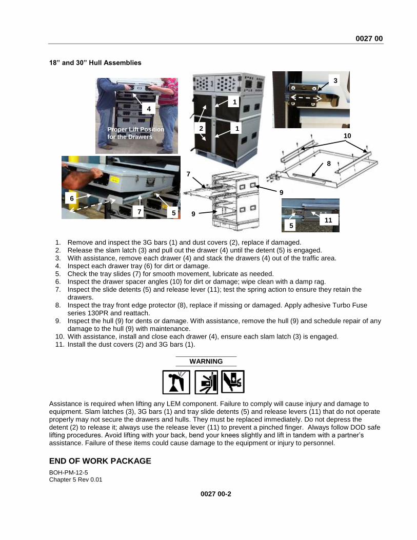
18” and 30” Hull Assemblies
1. Remove and inspect the 3G bars (1) and dust covers (2), replace if damaged. 2. Release the slam latch (3) and pull out the drawer (4) until the detent (5) is engaged. 3. With assistance, remove each drawer (4) and stack the drawers (4) out of the traffic area. 4. Inspect each drawer tray (6) for dirt or damage. 5. Check the tray slides (7) for smooth movement, lubricate as needed. 6. Inspect the drawer spacer angles (10) for dirt or damage; wipe clean with a damp rag. 7. Inspect the slide detents (5) and release lever (11); test the spring action to ensure they retain the
drawers. 8. Inspect the tray front edge protector (8), replace if missing or damaged. Apply adhesive Turbo Fuse
series 130PR and reattach. 9. Inspect the hull (9) for dents or damage. With assistance, remove the hull (9) and schedule repair of any
damage to the hull (9) with maintenance. 10. With assistance, install and close each drawer (4), ensure each slam latch (3) is engaged. 11. Install the dust covers (2) and 3G bars (1).
WARNING
Assistance is required when lifting any LEM component. Failure to comply will cause injury and damage to equipment. Slam latches (3), 3G bars (1) and tray slide detents (5) and release levers (11) that do not operate properly may not secure the drawers and hulls. They must be replaced immediately. Do not depress the detent (2) to release it; always use the release lever (11) to prevent a pinched finger. Always follow DOD safe lifting procedures. Avoid lifting with your back, bend your knees slightly and lift in tandem with a partner’s assistance. Failure of these items could cause damage to the equipment or injury to personnel.
END OF WORK PACKAGE
8
2
3
5 7
4 1
1
6
9
9
7
11 5
Proper Lift Position
for the Drawers 10

0028 00
BOH-PM-12-5 Chapter 5 Rev 0.01
0028 00-1
UNIT MAINTENANCE INSTRUCTIONS
FPU® SYSTEMS OPERATION MANUAL (INCLUDING REPAIR PARTS & SPECIAL TOOL LIST)
LIGHT EXPEDITIONARY MODULE (LEM) BOH FPU Field Pack/up Units
LEM CABINET BASE AND TWIST LOCK
INITIAL SETUP: Materiel/Parts References Foot Pads kit, Twist Lock Assembly, Pin and Lanyard Kit Chapter 2 WP 0009 00-1 and 00-2 Personnel Required Equipment Condition Two BOH LEM Cabinet Base Repairs Tools
Rivet Repair Kit, 7/16” Open End Wrench, Wire Cutter
INSPECT, REPAIR
NOTE During installation, removal or repair of the LEM cabinet base (1), ensure the twist lock threads (2) have sufficient lubrication applied.
1. Inspect the handle securing pin and lanyard (4), replace if missing or damaged. 2. Inspect the cabinet base (1) for dents, weld cracks or damage, repair any cracked welds. 3. Inspect the twist lock handle (3) for damage. 4. Remove and replace a damaged handle (3) by removing the two hex head screws (5) with a 7/16”
wrench.
2 1
4
5
4
3

0028 00
BOH-PM-12-5 Chapter 5 Rev 0.01
0028 00-2
Foot Pads
1. With an assistant, tip the cabinet base (1) on edge for inspection of the pads (2) only. 2. Place the cabinet base on a firm surface with the bottom up to safely replace the pads. 3. Remove the foot pad rivets; refer to rivet replacement, page 0023 00-1 and 00-2. 4. Replace the foot pads (2) and rivets from the kit.
NOTE It is recommended that all four pads be replaced to maintain a level LEM.
WARNING
Assistance is required when lifting the LEM cabinet base (1). Place the cabinet base on a firm surface with the bottom up to safely replace the pads. Always follow DOD safe lifting procedures. Avoid lifting with your back, bend your knees slightly and lift in tandem with a partner’s assistance. Failure to comply will cause injury and damage to equipment.
2
1

0028 00
BOH-PM-12-5 Chapter 5 Rev 0.01
0028 00-3
Twist Lock Assembly
1. Inspect the twist lock assembly (1) for damage. 2. Remove the pin (5) to rotate the star nut (4). 3. To replace the twist lock assembly (1), remove the handle hex screws (2) with the 7/16” wrench. 4. Remove the handle (3) and twist lock assembly; rotate the star nut (4) counterclockwise until the
bottom threads (6) are free. 5. Install a new twist lock assembly (1), from the kit. 6. Ensure there is lubrication on the twist lock threads (5); review chapter 2, WP 0009 00-1 and 00-2.
WARNING
Assistance is required when lifting the LEM cabinet base (1). Place the cabinet base on a firm, stable surface to replace the twist lock assembly. Failure to comply will cause injury and damage to equipment.
END OF WORK PACKAGE
3
2
5
6
4
1

BOH-PM-12-5 Chapter 5 Rev 0.01
This page was intentionally left blank

0029 00
BOH-PM-12-5 Chapter 5 Rev 0.01
0029 00-1
UNIT MAINTENANCE INSTRUCTIONS
FPU® SYSTEMS OPERATION MANUAL (INCLUDING REPAIR PARTS & SPECIAL TOOL LIST)
LIGHT EXPEDITIONARY MODULE (LEM) BOH FPU Field Pack/up Units
LEM MOUNTING PLATES
INITIAL SETUP: Materiel/Parts References None Chapter 2 WP 0007 00 Personnel Required Equipment Condition Two or more BOH LEM Mounting Plate Repairs Tools
None
INSPECT, REPAIR
1. Inspect the receiver and flange welds for cracks on mounting bases (1, 2 & 3); only a certified welder should repair weld cracks.
2. Ensure the mounting plate (1, 2 & 3) is securely bolted or welded in position.
WARNING
Assistance from multiple personnel is required when lifting the LEM Mounting Plate (1, 2 & 3). Always follow DOD safe lifting procedures. Avoid lifting with your back, bend your knees slightly and lift in tandem with a partner’s assistance. Failure to comply will cause injury and damage to equipment.
1
3
2
1, 2 & 3

0029 00
BOH-PM-12-5 Chapter 5 Rev 0.01
0029 00-2
Mounting Plate Receiver
1. Inspect the mounting base plate and receiver for cracks on mounting plates (1, 2 & 3), report weld cracks to maintenance.
2. Inspect the cutout edges (4) for distortion, dents, burs, etc. ; only a certified welder should make these repairs.
3. Ensure the mounting plate (1, 2 &3) is securely bolted or welded in position.
WARNING
Protective gloves should be worn when handling metal parts in high temperatures. Failure to wear gloves may result in burning or blistering of the skin upon contact. Eye protection should be worn when grinding, drilling or welding. Failure to comply will result in injury to personnel.
Repairs Requiring Welding Welding repairs are only required when the FPU SYSTEM module is pierced, punctured, or cracked. Standard welding principles and materials apply to FPU SYSTEM repairs. Welding procedures will not be discussed in this tech manual. Refer to TC 9-237.
END OF WORK PACKAGE
1
3
2
4 4 4
1, 2 & 3
4