fpga implementation of an adaptive filter
TRANSCRIPT
860 IEEE TRANSACTIONS ON INDUSTRIAL ELECTRONICS, VOL. 58, NO. 3, MARCH 2011
FPGA Implementation of an Adaptive Filter Robustto Impulsive Noise: Two Approaches
Alfredo Rosado-Muñoz, Manuel Bataller-Mompeán, Emilio Soria-Olivas, Claudio Scarante, andJuan F. Guerrero-Martínez, Member, IEEE
Abstract—Adaptive filters are used in a wide range of ap-plications such as echo cancellation, noise cancellation, systemidentification, and prediction. Its hardware implementation be-comes essential in many cases where real-time execution is needed.However, impulsive noise affects the proper operation of the filterand the adaptation process. This noise is one of the most damagingtypes of signal distortion, not always considered when implement-ing algorithms, particularly in specific hardware platforms. Field-programmable gate arrays (FPGAs) are used widely for real-timeapplications where timing requirements are strict. Nowadays,two main design processes can be followed for embedded systemdesign, namely, a hardware description language (e.g., VHDL)and a high-level synthesis design tool. This paper proposes theFPGA implementation of an adaptive algorithm that is robustto impulsive noise using these two approaches. Final comparisonresults are provided in order to test accuracy, performance, andlogic occupation.
Index Terms—Adaptive filters, field-programmable gate array(FPGA), hardware design languages, high-level synthesis (HLS),impulsive noise.
I. INTRODUCTION
ADAPTIVE systems are a fundamental tool in digital sig-nal processing (DSP). Adaptive filters are appropriate
in temporal variant environment applications where statisticalparameters of signals change over time and, additionally, non-linear characteristics are foreseen in the analyzed or predictedprocess. A typical application in communication systems is themultipath distortion channel resulting in intersymbol interfer-ence (ISI); ISI also brings on higher bit error rate [1]. In thiscase, it is necessary to design a filter to compensate channeldistortion; adaptive equalization techniques have been widelystudied and tested. This example belongs to a group of applica-tions known as prediction, where two types exist, namely, futurevalue (forward prediction) or past value prediction (backwardprediction). Other prediction applications of adaptive filteringare speech processing or spectral signal estimation. Activenoise cancellation is also an important field where adaptive
Manuscript received May 30, 2008; revised January 29, 2009; acceptedApril 6, 2009. Date of publication June 5, 2009; date of current versionFebruary 11, 2011.
A. Rosado-Muñoz, M. Bataller-Mompeán, E. Soria-Olivas, andJ. F. Guerrero-Martínez are with the Digital Signal Processing Group,Department of Electronic Engineering, University of Valencia, 46100 Valencia,Spain (e-mail: [email protected]; [email protected]; [email protected]; [email protected]).
C. Scarante was with the University of Padova, 35131 Padova, Italy (e-mail:[email protected]).
Color versions of one or more of the figures in this paper are available onlineat http://ieeexplore.ieee.org.
Digital Object Identifier 10.1109/TIE.2009.2023641
filtering is used [2]. System identification is also an importantarea in control systems; in this case, adaptive filtering is used fortransfer function identification of an unknown system by meansof its inputs and outputs. Acoustic environment modeling forsonar applications is an example [3].
The structure of an adaptive algorithm consists of a temporalvariant system where the transfer function directly depends onthe statistical characteristics of the input signal, an algorithmconnecting the inputs, and a signal informing about the errorobtained by the adaptive system. Multiple adaptive algorithmsexist [4], [5], but most of them assume that the adaptive systemobtains an error following a Gaussian distribution. However, inmany real problems, the noise encountered is more impulsivethan the one predicted by a Gaussian distribution. Examplesfor this problem are underwater acoustic noise, low-frequencyatmospheric noise, and many types of man-made noise [6]. Inaddition, the presence of outliers, either at the input signal or atthe desired signal, may cause the adaptive algorithm to becomeunstable. For this reason, different adaptive algorithms that arerobust to impulsive noise have been proposed [7]–[9] in orderto provide proper operation.
Usually, impulsive noise cancellation is achieved by meansof independent filter techniques. Impulsive noise suppression inspeech is very important for clear voice communications, e.g.,using a statistical estimator [10] or in room acoustics using adigital filter using fuzzy reasoning [11]. In digital motor controlsystems, thyristor power converters need accurate synchroniza-tion, and impulsive noise might cause malfunction. Here, amultistage signal processing using a finite-impulse response(FIR) predictive filter is used [12]. For electrocardiogram signalprocessing, impulsive noise suppression is carried out usingnonlinear M-filters, namely, median and myriad filters [13]. Inimage processing, impulsive noise removal is an important re-search area, e.g., in video broadcasting [14] and image filtering[15], seldom applying an adaptive filtering technique.
Due to computational requirements, hardware implemen-tation of adaptive systems is not always straightforward, re-stricting the range of applications where they can be applied.However, a high-performance low-cost system on chip imple-mentations of DSP algorithms is receiving increased attention.Implementation platforms of DSP algorithms range from anapplication-specific integrated-circuit (ASIC) custom chip togeneral-purpose processor or DSP microprocessors. While DSPmicroprocessors provide flexibility and programmability forimplementation of a large set of algorithms, their design issuboptimal for specific applications due to the sequential exe-cution that limits possibilities for parallel operation. Moreover,
0278-0046/$26.00 © 2009 IEEE

ROSADO-MUÑOZ et al.: FPGA IMPLEMENTATION OF AN ADAPTIVE FILTER ROBUST TO IMPULSIVE NOISE 861
power consumption is high for portable application usage,and an internal hardware structure is not optimized. On theother hand, ASIC could provide the solution that meets allthe constraints. However, they lack the flexibility existing ina DSP processor or field-programmable gate array (FPGA) andleave no room for reconfigurability of their circuitry. Hence, thedesign and development process for an ASIC can be both timeconsuming and expensive, being considered only when high-volume manufacturing is foreseen or very strict applicationsrequire such a design.
Nowadays, the use of FPGAs is increasing. They are power-ful hardware devices, combining the main advantages of ASICand DSP processors, since they provide both a programmableand a dedicated hardware solution [16], [17], which makesthem very attractive devices for rapid prototyping. Even if thefinal design will be implemented in an ASIC, it is usual touse an FPGA as the prototyping device due to factors suchas time and cost [18]. Moreover, an FPGA is more efficient inpower consumption, an advantage for battery-operated systems,and, for the same application, requires less clock system speedcompared to a DSP or a general-purpose processor, offeringbetter electromagnetic compatibility properties. Industrial ap-plications are taking advantage of this hardware; FPGA imple-mentations are used, e.g., to control an induction motor drive[19], implement active control filters [20], perform automaticonline diagnosis algorithm for broken-bar detection on induc-tion motors using discrete wavelet transform [21], and mitigatethe distortion in RF power amplifiers [22].
Thus, for a wide range of applications, FPGA implemen-tation might be the best option. However, in the case of lowsampling frequency requirements or no low power consumptionneeds, some other devices could be more suitable. In this paper,FPGAs are the target hardware.
Apart from usual reprogrammable resources (lookup table(LUT), slices formed from LUT, registers, etc.), modern FPGAscontain many resources that support DSP applications such asembedded multipliers, multiply accumulate units, intellectualproperty cores for advanced specific functions, and processorcores for simpler programming. Some of the resources areimplemented in the FPGA fabric and optimized for high-performance concurrent operation and low power consumption.
Usually, the task of describing a complex system fora hardware implementation is still very hard. FPGAs arenormally used for applications with tremendous time to marketconstraints; thus, there is a need for design tools that are ableto achieve this. In a traditional approach, a design tool takes theVHDL description of the hardware and generates a bitstream(configuration file for the FPGA device). Nowadays, the use ofhigh-level synthesis (HLS) tools is increasing, enabling design-ers to enter designs at a much higher level of abstraction. Suchan HLS tool would accelerate the design process by taking thealgorithmic description of the required hardware, introducingcertain area and performance requirements according to thedesign needs, and automatically generating the bitstream.This paper develops VHDL and HLS implementation for anovel algorithm (adaptive impulsive noise filtering), providingsome hints and comparisons for each design process. Xilinxdevices and software environment have been chosen. Other
Fig. 1. Scheme of an adaptive filter.
manufacturers offer similar devices and tools (e.g., Altera withDSP Builder, Accel DSP from Xilinx, and SynplifyDSP); inthis case, Xilinx devices are only considered.
A combination of adaptive filtering, impulsive noise im-munity, and hardware implementation is an area where fewreferences can be found, mainly focused in the digital imageprocessing field [23]–[25]. This paper deals with the FPGAhardware implementation of an adaptive algorithm that is robustto impulsive noise developed in [26]. This algorithm offers alow computational cost by employing a cost function widelyused in independent component analysis (ICA). Some refine-ments to the original algorithm have been introduced to reducecomputational cost without affecting functionality.
The remainder of this paper is outlined as follows. Section IIshows the proposed cost function and the algorithm descrip-tion. Section III describes the specifications of the system,the proposed stages carried out to perform the calculation,and the optimal architecture to balance speed and area in thetwo hardware implementations proposed. Section IV showsthe simulation results and design verification and provides aperformance study in terms of the area, time, and accuracy.Finally, this paper concludes with a summary.
II. ALGORITHM DESCRIPTION
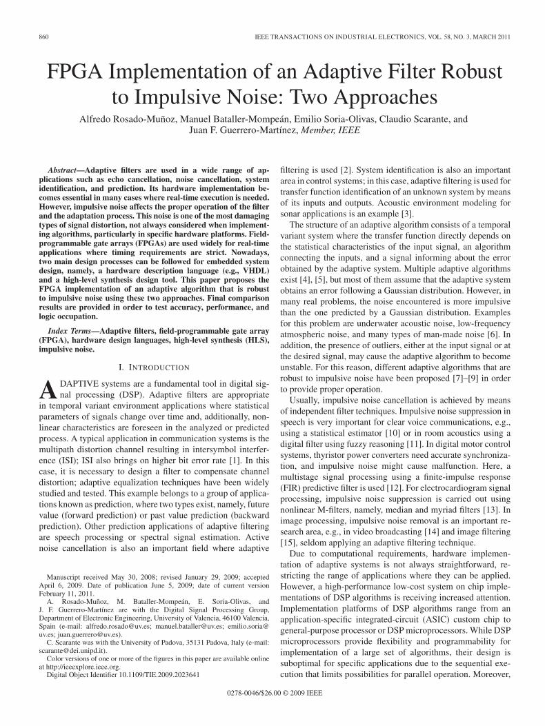
An adaptive system is composed of two modules (Fig. 1).1) A temporal variant system (adaptive system). Most of
the applications propose a digital FIR filter definedin a time instant n by a coefficient vector wn =[wn(0), wn(1), . . . , wn(L − 1)], using an input vec-tor xn = [x(n), x(n − 1), . . . , x(n − L + 1)] to calcu-late the output signal y(n) as the wn and xn convolution.
2) An adaptive algorithm. This module adjusts the coeffi-cients so that the adaptive system output y(n) and thedesired signal d(n) are equal. The similarity betweenboth signals is given by the error signal e(n) definedas d(n) − y(n). The error signal e(n) is used to ad-just the coefficients of the adaptive system for the nexttime instant. Different algorithms exist for the coefficientadjustment.
Adaptive algorithms are based on the minimization of acertain cost function (optimization problem). The most widelyused cost function is the quadratic error. This cost functionis optimum when errors follow a Gaussian distribution [4].However, it is not a good choice in the presence of outliers or
862 IEEE TRANSACTIONS ON INDUSTRIAL ELECTRONICS, VOL. 58, NO. 3, MARCH 2011
impulsive noise. In [26], the use of a cost function commonlyused in ICA (1) provides a good result in the presence of out-liers as in the case of impulsive noise, where β ∈ �+ controlsthe sensitivity to large outliers in the value of signal error e(n)
J(n) =log [cosh (β · e(n))]
β. (1)
By using the Delta rule [4], [5] for the update of the coeffi-cients, we obtain the following equation where μ ∈ �+ is thelearning rate:
wn+1 = wn + μ · tanh [β · e(n)] · xn. (2)
Equation (2) shows two attractive features.1) The proposed cost function is noise robust: since the
hyperbolic tangent saturates to ±1 for extreme values.2) Easy hardware implementation: An efficient hardware
implementation for the hyperbolic tangent based on fuzzylogic is used, giving
tanh (β · e(n))
={
sign (e(n)) , if |e(n)| > 1/β−e(n) · |e(n)| · β2 + 2 · β · e(n), if |e(n)| ≤ 1/β.
(3)
Therefore, the update of the algorithm coefficients in (2) isgiven by
wn+1
={wn+μ ·sign [e(n)]·xn, if |e(n)|>1/βwn+μ·[2β−β2 ·|e(n)|]·e(n)·xn, if |e(n)|≤1/β. (4)
The value of beta is very relevant since it controls whichoutliers are taken into account by the adaptive system. Thisparameter is related to the variance of the error produced bythe adaptive system. The value of β can be modified itera-tively according to the evolution of the error in the learningprocess. We have taken the classical threshold of three standarddeviations to consider a pattern as an outlier. Moreover, sincetanh(|3|) = |0.96|, i.e., a value close to unity, the parameter βcan be obtained
β =3
(m + 3 · σ)(5)
where m is the mean value of the error signal and σ is itsstandard deviation estimated in an N -length window containingthe last errors [26].
This threshold for the outliers can be modified, providingdifferent levels of immunity to impulsive noise.
III. HARDWARE IMPLEMENTATION
From an external hardware view, the interface is defined withtwo 12-b data inputs, namely, x(n) and d(n), as the reset andclock signals, and DATAIN_VALID, a synchronization signalfrom a hypothetical acquisition device, to inform the FPGA thatnew data are ready for processing. Regarding the outputs, thesystem provides 12-b filtered data y(n) and a synchronizationsignal DATAOUT_VALID to inform a potential subsequentsystem that data have been calculated and a filter result sampleis available.
As indicated in (4), the calculation process for coefficientupdate requires the values of e(n), β, and μ. However, forhardware implementation, some modifications are done. Theupdate algorithm can be divided into four logic steps.
Step 1) Calculation of y(n) according to (6). In this case, tis the transpose and L = 9
y(n) =L−1∑k=0
x(n − k) · wn(k) = xtn · wn. (6)
Step 2) Calculation of e(n). The estimation error e(n) isthe difference between the desired response d(n)and the adaptive system output y(n), i.e., e(n) =d(n) − y(n).
Step 3) Calculation of β. Typically, most of the applicationsin adaptive filtering have zero mean signals; then,when the number of samples is high, the valueof m can be rounded to zero [4]. Moreover, as βcontrols the outlier immunity, and thus, a fixed valueis not necessary, we have experimentally provedthat, using both the standard deviation or its square(i.e., the variance), the resultant β does not affectthe system behavior. Finally, (5) becomes β ≈ 1/σ2.This is very useful because an iterative calculationprocedure for the variance [28] can be used (7) andβ calculation is simplified
σ2(n) =n − 1
n· σ2(n − 1) +
1n − 1
(e(n) − m)2 . (7)
For a high number of samples (n �), (7) can beapproximated as
σ2(n) = 0.95 · σ2(n − 1) +e2(n)
nif n = 0, σ2(n) = 1.
(8)
Step 4) Calculation of next sample coefficient valueswn+1(k). The filter coefficients are updated basedon (4), which can be rewritten as indicated in thefollowing equation where wn(k) and wn+1(k) arethe current and updated coefficients, respectively(k ∈ {0, . . . , 8}), μ is the learning rate, and x(n −k) is the delay-line samples provided by the input ofthe filter:
wn+1(k)
=
⎧⎪⎨⎪⎩
wn(k)+μ · sign [e(n)] · x(n − k), if |e(n)|>σ2
wn(k)+μ ·[
2σ2 − |e(n)|
(σ2)2
]·e(n) · x(n − k), if |e(n)|≤σ2.
(9)
As appreciated, this step is the most costly in terms ofrequired computations.
A. Implementation Considerations
Computing floating-point arithmetic in an FPGA is possible,but it is not the most efficient method. In fact, it is very intensivein terms of logic resource usage and does not take full advan-tage of the parallelization possibilities offered by an FPGA. All

ROSADO-MUÑOZ et al.: FPGA IMPLEMENTATION OF AN ADAPTIVE FILTER ROBUST TO IMPULSIVE NOISE 863
Fig. 2. State machine used for VHDL filter implementation.
calculations are therefore mapped to a fixed point, but this canintroduce analog-to-digital conversion quantization error, coef-ficient quantization error, overflow error, and round-off error.All of these issues must be addressed and handled properly toreduce the errors committed by fixed-point arithmetic.
The first decision taken in fixed-point arithmetic is to keepa limited number of decimal digits. The number of decimalpositions required for a given algorithm to converge depends onthe algorithm. For instance, if two decimal places are sufficientfor accurate data processing, this can easily be obtained bymultiplying the filter’s coefficients by 100 and truncating to aninteger value. Dividing the output by 100 recovers the value.Since multiplying and dividing by powers of two can be doneeasily in hardware by shifting bits, a power of two can be usedto simplify the process. In this case, we multiply by 128, whichwould require seven extra bits in hardware, but precision isimproved for internal calculations. In addition, divisions mustbe corrected with a subsequent multiplication. Addition andsubtraction require no adjustment.
In this paper, we use 12-b normalization. This means that thescale constant is s = 2047, being the size of all data inputs andoutputs.
B. FPGA Implementation Based in VHDL
In order to perform all the required calculations for eachnew data sample (iteration), we defined a finite state machine
(FSM) shown in Fig. 2. The FSM is in State0 waiting fora new data sample; once it is received, the FSM increasesthe state every new clock cycle in order to perform differentcalculations at each state. It is necessary to obtain several resultsneeded for further calculations; thus, most of these calcula-tions are intermediate values (internal_∗ signals). After sixclock cycles, all the calculation process is completed, includingthe output value and coefficients’ update, being ready for anew data sample. For the FSM to work properly, the signalDATAIN_VALID must be high during all the states. There alsoexists an ENABLE_INT signal preventing the FSM to start anew calculation for the same input data, only allowing a newcalculation when DATAIN_VALID goes low and then high, i.e.,new input data are received.
All the calculations are distributed among the states, ob-taining partial results to optimize logic resources. In this case,nine 18-b multipliers, one divider 25 by 14-b length, and someadditional adders and subtracters are used. We have paid specialattention to multiplications and divisions, being optimized toshare the same arithmetic unit in different states. The dataflow for the algorithm is described step by step in Fig. 3. Theresult from the division takes one additional clock cycle tobe calculated; it is marked as a dotted line in the data flowof Fig. 3.
In State S1, the filter output signal y(n) is calculated. Thisstate makes use of nine multiplications, eight additions, andone FIFO register to store the new sampled input and theL − 1 previous inputs (inputvector). In State S2, calculation
864 IEEE TRANSACTIONS ON INDUSTRIAL ELECTRONICS, VOL. 58, NO. 3, MARCH 2011
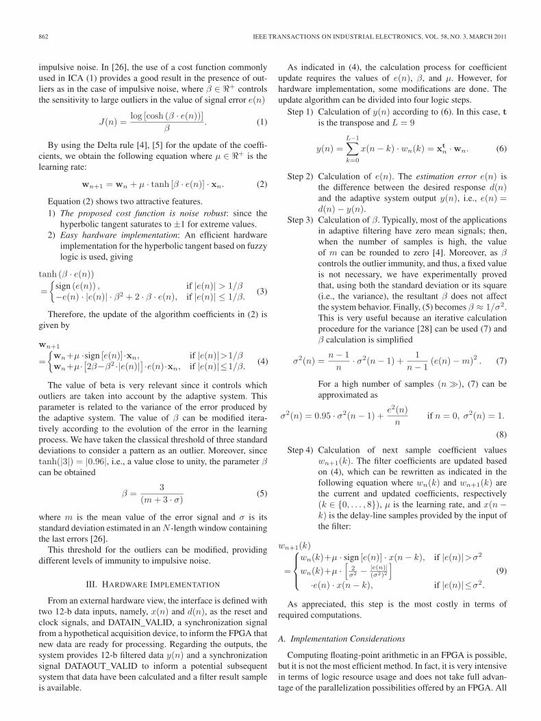
Fig. 3. Data flow for the state machine in VHDL filter implementation.
of internal_r, internal_s, error, and the product μ · x(n)is done. Internal_r is the result of a division; then, itwill be ready for the next state (S3), and the product μ ·x(n) is stored in a second FIFO register called updatevector.Here, two multiplications, one division, and one addition arerequired.
In the State S3, the variance (sigmasquare), internal_t, andinternal_u values are obtained, requiring a single multiplica-tion, an addition, and a division. Concerning State S4, it com-putes one division for the calculation of internal_v. In StateS5, internal_y and internal_z are calculated using a multi-plication and an addition. Finally, in State S6, the coefficients’update algorithm is performed for all the kth coefficients, usingall the intermediate values obtained from previous states byinternal_∗ signals.
A balance between logic resource usage and performance hasbeen considered, obtaining all the results in the fewer states aspossible. Special attention is paid to the division operation as itis costly in terms of resources; thus, only one division moduleis used to perform all the divisions needed in the algorithm. Byusing this approach, after six clock cycles, a result is obtained,which means that a sampling data rate of one-sixth of the clocksignal could be achieved for the input signal, thus being theoutput update rate.
C. FPGA Implementation Based on Simulink SystemGenerator HLS Tool
Different implementation strategies can be followed whenusing an HLS tool, some closer to the software algorithm
ROSADO-MUÑOZ et al.: FPGA IMPLEMENTATION OF AN ADAPTIVE FILTER ROBUST TO IMPULSIVE NOISE 865
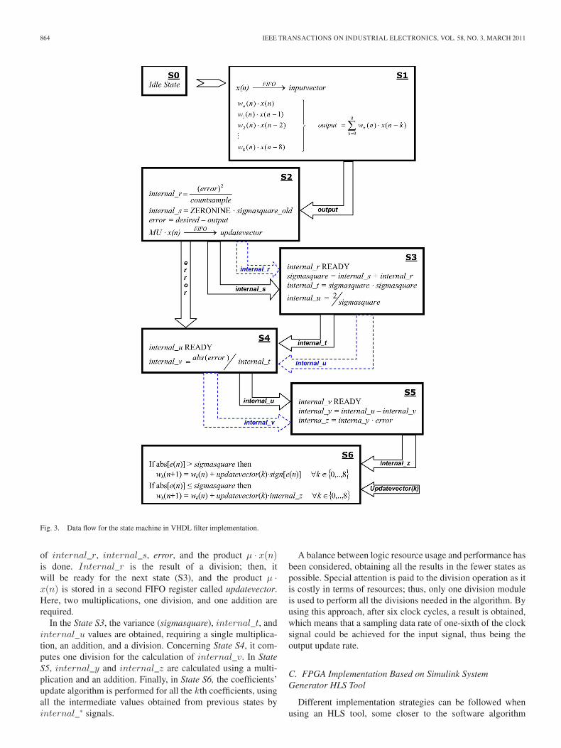
Fig. 4. Top-level block diagram for the HLS tool.
and some others to the hardware level. However, the mainadvantage compared to hardware description languages lies inthe reduced knowledge required in the field of hardware design.For the Simulink–Xilinx System Generator (XSG) tool, oncethe software algorithm is obtained in Matlab, mathematicaloperations must be converted to predefined blocks given inlibraries (blockset from XSG library), interconnecting themaccording to the computations required. Finally, the designersets up some options for data bit width and the type of arith-metic to implement. This blockset provides a range of high-level functionality, from arithmetic operations to complex DSPfunctions. Simulink, together with XSG and Xilinx ISE designsoftware packages, is used for the filter implementation. Inthis case, the target was the simplicity design entry, withoutfurther refinement in the modules, as a software designerwould do. A block diagram of the proposed system is shownin Fig. 4.
All the calculations are carried out using signed fixed-pointarithmetic (2’s complement). In the case of overflow, the chosenoption has been to saturate to the largest positive or smallestnegative value, and for quantization, rounding is done. Internalcalculations are carried out using double precision. The mainparts of the proposed system are as follows.
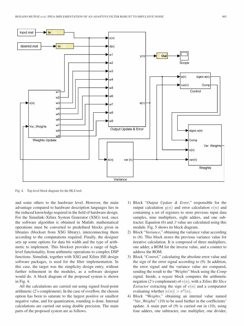
1) Block “Output Update & Error,” responsible for theoutput calculation y(n) and error calculation e(n) andcontaining a set of registers to store previous input datasamples, nine multipliers, eight adders, and one sub-tracter. Equation (6) and β value are calculated using thismodule. Fig. 5 shows its block diagram.
2) Block “Variance,” obtaining the variance value accordingto (8). This block stores the previous variance value foriterative calculation. It is composed of three multipliers,one adder, a ROM for the inverse value, and a counter toaddress the ROM.
3) Block “Control,” calculating the absolute error value andthe sign of the error signal according to (9). In addition,the error signal and the variance value are compared,sending the result to the “Weights” block using the Compsignal. Inside, a negate block computes the arithmeticnegation (2’s complement) of e(n), with a Xilinx Bit SliceExtractor extracting the sign of e(n) and a comparatorevaluating whether |e(n)| > σ2(n).
4) Block “Weights,” obtaining an internal value named“Var_Weights” (10) to be used further in the coefficients’update. A main part of (9) is carried out in (10), usingfour adders, one subtracter, one multiplier, one divider,

866 IEEE TRANSACTIONS ON INDUSTRIAL ELECTRONICS, VOL. 58, NO. 3, MARCH 2011
Fig. 5. “Output Update & Error” block diagram.
and five shift blocks to perform a right shift in the inputsignal. By using these resources, products by constants0.05 and 0.025 are reduced to shift and add operations
V ar_Weights
=
⎧⎪⎪⎨⎪⎪⎩
0.025 · sign(n), if |e(n)| > σ2(n)0.05 ·
[e(n)σ2
]
−0.025 ·[
e(n)σ2
]·[|e(n)|
σ2
], if |e(n)| ≤ σ2(n).
(10)
5) Block “Weights Update,” responsible for updating theweight values of the adaptive filter using the value ob-tained in block “Weights”. This block completes thecalculation of (9) and contains registers to store pre-vious values of data input samples, 97 multipliers and9 accumulators.
In this implementation, simplicity and design time to de-scribe the design in the HLS tool has been the goal. Thus,
the previously designed Matlab algorithm code has been easilymigrated without special attention to optimization in resourcesand performance. As a result, the tool implemented arithmeticunits concurrently, increasing the performance at the cost ofusing 21 18-b multipliers, one divider, one ROM, and additionaladders and subtracters.
IV. RESULTS
By using the HLS approach, the system is described as adata flow, simpler, and faster than in VHDL. Some functionalmodules exist in a library, and others can be done manually, butin general, the description of complex systems typically used inan embedded system design becomes easier. In contrast, somespecific refinements cannot be done, and optimization in termsof performance is not simple. System Generator for HLS andModelSim for VHDL descriptions have been used to simulatethe two approaches for hardware implementation.

ROSADO-MUÑOZ et al.: FPGA IMPLEMENTATION OF AN ADAPTIVE FILTER ROBUST TO IMPULSIVE NOISE 867
Fig. 6. Error versus iterations for different approaches (µ = 0.025).
The proposed adaptive algorithm implementation was testedon a system identification application with impulsive noisecontribution. In this case, x(n) is the stimulus signal, whichfeeds directly to the unknown system and the adaptive fil-ter. The output of the unknown system, d(n) or desiredsignal, is corrupted by impulsive noise and contaminatedwith Gaussian noise, not correlated to the adaptive systeminput. The input signal x(n) and desired signal d(n) arewide sense stationary and zero mean processes. The un-known system is an FIR filter with coefficients wunknown =[−0.1,−0.2,−0.3,−0.4, 0.5, 0.4, 0.3, 0.2, 0.1]. This simula-tion has been widely used in a great number of publications,thus considered a good test for this system and comparison toothers [7]–[9].
In order to evaluate the goodness of the proposed system,the difference between the unknown and the filter-obtainedcoefficients is calculated according to
errorn(dB) = 10 · log10
[‖wn − wunknown‖2
‖wunknown‖2
]. (11)
Fig. 6 shows the error achieved. As can be seen, thespeed of convergence is fast, in less than 400 iterations(samples), and the filter gets an excellent identification valueof coefficients for the unknown system (the error is below−25 dB). As an example, in iteration 417, the coefficientvalues obtained by the adaptive system are wn = [−0.092,−0.206, −0.290, −0.411, 0.515, 0.395, 0.288, 0.205, 0.113],which are close to the unknown system values wunknown. BothVHDL and HLS hardware results are very close to the resultsobtained by floating-point software, although, due to precisionerrors, the floating-point result gives a lower error.
Regarding noise immunity, for simulation and hardware re-sults, Fig 7 shows the filter output result y(n) compared tothe unknown system output d(n) for simulation [Fig. 7(a)]and hardware implementation [Fig. 7(b)]. Despite the noise,the algorithm identifies the system and adjusts coefficientsaccordingly; it can be observed that d(n) and y(n) signals inFig. 7(a) and (b) are the same except for the noise, as expected.
Some minor differences are appreciated between simulationand hardware implementation.
A. Device Implementation
Different device implementations have been done; Tables Iand II show the results for VHDL and HLS descriptions,respectively. For occupation and performance comparison pur-poses, three Xilinx devices have been used, namely, a low-cost Spartan3 and two leading edge devices from Virtex4 andVirtex5 device families.
Logic occupation is very similar for VHDL and HLS exceptfor the usage of multiplier units (9 for VHDL and 21 for HLS);apart from that, logic resources used by an HLS are lower.However, for VHDL implementation, the target device could besimpler than in HLS due to the low number of multiplier units.Regarding performance, the HLS implementation calculates theresult in a single clock cycle, being six clock cycles necessaryfor the VHDL. Thus, despite the fact that the maximum clockfrequency is lower in HLS, the maximum achievable samplingrate is higher than in VHDL. In any case, a sampling data ratefrom 1.58 to 12.32 MHz could be achieved.
In Virtex5 family, clock frequency increases dramaticallycompared to the other devices, mainly due to silicon fabric andnew reconfigurable architecture from the manufacturer.
One of the most restricting design modules for performancein both designs is the division as it is calculated in a single clockcycle. Several division approaches have been explored, consid-ering that single clock division could be optimum. Pipelineddivision does not match the requirements in this design becausea division result is further divided before the final result, notallowing the pipeline scheme.
Final hardware verification has been carried out in aXilinx Spartan3E device family (XC3S500E-4) included in theDigilent Spartan3E starter board; the data acquisition is doneusing an LTC1407A-1 serial SPI dual 14-b analog-to-digitalconverter from linear technology, reduced to 12-bit to ac-commodate filter input data length. The filter output result isconverted using an LTC2624 12-b serial SPI digital-to-analogconverter from linear technology. National Instruments NIUSB-6008 data acquisition board is used to generate filterinputs and read FPGA filter output from a PC computer andevaluate FPGA real-time processing, performance, and accu-racy. Fig. 8 shows a photograph of the test system and theresults obtained from the FPGA device.
V. CONCLUSION
The implementation of a useful adaptive filter to removeimpulsive noise for system identification or prediction is doneusing FPGA devices. Furthermore, the FPGA implementationallows the usage in hardware platforms where low powerconsumption is required. In contrast to other devices suchas DSP processors, a high data sample rate is achieved at arelatively slow system clock frequency operation, thus reducingelectromagnetic interferences.
In addition, two different implementation procedures havebeen followed. The first method used VHDL, where hardwareimplementation details are optimized and the filter structure can

868 IEEE TRANSACTIONS ON INDUSTRIAL ELECTRONICS, VOL. 58, NO. 3, MARCH 2011
Fig. 7. Output of the unknown system d(n) and the filter y(n) for (a) simulation and (b) real-time hardware implementation.
TABLE IVHDL IMPLEMENTATION RESULTS IN XILINX FPGA DEVICES
TABLE IIHLS IMPLEMENTATION RESULTS IN XILINX FPGA DEVICES
be defined more precisely. The second implementation methodused an HLS environment; in this case, a fast design entry canbe done without the need of extensive hardware implementationknowledge. The proposed structure using the HLS was an easyfilter design as an inexperienced hardware designer would do.
Simulations and real-time hardware implementation resultsshow that both implementations are very accurate, being verysimilar in accuracy when compared to a floating-point resultand also between VHDL and HLS. In the case of resource con-sumption and speed of operation, different device implementa-tions have been done, showing that for the same device, similarresources are used for both approaches. Regarding speed ofoperation, higher speed of system clock can be achieved using
Fig. 8. Hardware testing system and results for the proposed adaptive filter.
VHDL description, but due to the need of six clock cycles toperform the calculation of filter output for every data sample,the HLS description offers greater data sample frequency.
We can state that an HLS design environment is very useful,particularly for those very complex designs or inexperiencedhardware designers. An HLS is closer to the software and algo-rithm level design, making hardware migration from simulation

ROSADO-MUÑOZ et al.: FPGA IMPLEMENTATION OF AN ADAPTIVE FILTER ROBUST TO IMPULSIVE NOISE 869
software a relatively easy task. The evaluated HLS (SimulinkSystem Generator), and any HLS in general, does not allowspecific control for low-level design aspects. However, due tothe specific libraries of optimized components, good perfor-mance results can be obtained. On the other hand, a high levelof optimization can be achieved using a low-level hardwaredesign, such as VHDL description, which requires more timeand effort and good expertise in the field.
REFERENCES
[1] J. G. Proakis, Digital Communications. New York: McGraw-Hill, 2008.[2] J. Benesty, T. Gänsler, D. R. Morgan, M. M. Sondhi, and S. L. Gay, Ad-
vances in Network and Acoustic Echo Cancellation. Berlin, Germany:Springer-Verlag, 2001.
[3] E. S. Nejevenko and A. A. Sotnikov, “Adaptive modeling for hydroa-coustic signal processing,” Pattern Recognit. Image Anal., vol. 16, no. 1,pp. 5–8, Jan. 2006.
[4] A. Sayed, Fundamentals of Adaptive Filtering. New York: Wiley, 2003.[5] B. Widrow and S. Stearns, Adaptive Signal Processing. Englewood
Cliffs, NJ: Prentice-Hall, 1985.[6] C. L. Nikias and M. Shao, Signal Processing With Alpha-Stable Distribu-
tions and Applications. New York: Wiley, 1995.[7] C. Rusu and C. F. N. Cowan, “Adaptive data echo cancellation using cost
function adaptation,” Signal Process., vol. 80, no. 11, pp. 2457–2473,Nov. 2000.
[8] D. P. Mandic, E. V. Papoulis, and C. G. Boukis, “A normalised mixednorm adaptive filtering algorithm robust under impulsive noise interfer-ence,” in Proc. Int. Conf. Acoust., Speech, Signal Process. VI, 2003,pp. 333–336.
[9] J. Chambers and A. Avlonitis, “A robust mixed-norm adaptive fil-ter algorithm,” IEEE Signal Process. Lett., vol. 4, no. 2, pp. 46–48,Feb. 1997.
[10] M. A. Gandhi, C. Ledoux, and L. Mili, “Robust estimation methodsfor impulsive noise suppression in speech,” in IEEE Int. Symp. SignalProcess. Inf. Technol., 2005, pp. 755–760.
[11] I. Akira, O. Mitsuo, and O. Hitoshi, “A digital filter for estimation ofimpulsive noise and vibration by introducing fuzzy reasoning and itsapplication to room acoustics,” J. Acoust. Soc. Jpn., vol. 55, no. 1, pp. 32–36, 1999.
[12] O. Vainio and S. J. Ovaska, “Noise reduction in zero crossing detectionby predictive digital filtering,” IEEE Trans. Ind. Electron., vol. 42, no. 1,pp. 58–62, Feb. 1995.
[13] T. P. Pander, “A suppression of an impulsive noise in ECG signalprocessing,” in Proc. Conf. IEEE Eng. Med. Biol. Soc., 2004, vol. 1,pp. 596–599.
[14] J. Armstrong, H. A. Suraweera, C. Chai, and M. Feramez, “Impulsenoise mitigation techniques for OFDM receivers and their application indigital video broadcasting,” Mediterr. J. Electron. Commun., vol. 1, no. 1,pp. 1–10, Oct. 2005.
[15] I. Aizenberg, T. Bregin, and D. Paliy, “Method for the impulsive noisedetection and its application for the improvement of the impulsive noisefiltering algorithms,” in Image Process. Conf., San Jose, CA, 2002,vol. 4667, pp. 204–214.
[16] K. Benkrid, D. Crookes, and A. Benkrid, “Design and implementation of anovel algorithm for general purpose median filtering on FPGAs,” in Proc.ISCAS, 2002, vol. 4, pp. 425–428.
[17] U. M. Baese, Digital Signal Processing With Field Programmable GateArrays, 3rd ed. Berlin, Germany:Springer-Verlag, 2007.
[18] G. Spivey, S. S. Bhattacharyya, and K. Nakajima, “Logic foundry: Rapidprototyping of FPGA-based DSP systems,” in Proc. ASP-DAC, 2003,pp. 374–381.
[19] D. Zhang and H. Li, “A stochastic-based FPGA controller for an inductionmotor drive with integrated neural network algorithms,” IEEE Trans. Ind.Electron., vol. 55, no. 2, pp. 551–561, Feb. 2008.
[20] Z. Shu, Y. Guo, and J. Lian, “Steady-state and dynamic study of activepower filter with efficient FPGA-based control algorithm,” IEEE Trans.Ind. Electron., vol. 55, no. 4, pp. 1527–1536, Apr. 2008.
[21] A. Ordaz-Moreno, R. de Jesus Romero-Troncoso, J. A. Vite-Frias,J. R. Rivera-Gillen, and A. Garcia-Perez, “Automatic online diagnosisalgorithm for broken-bar detection on induction motors based on discretewavelet transform for FPGA implementation,” IEEE Trans. Ind. Electron.,vol. 55, no. 5, pp. 2193–2202, May 2008.
[22] J. L. Mato, M. Pereira, J. J. Rodríguez-Andina, J. Farina, E. Soto, andR. Perez, “Distortion mitigation in RF power amplifiers through FPGA-based amplitude and phase predistortion,” IEEE Trans. Ind. Electron.,vol. 55, no. 11, pp. 4085–4093, Nov. 2008.
[23] F. J. Gallegos-Funes and V. I. Volodymyr, “Real-time image filteringscheme based on robust estimators in presence of impulsive noise,” Real-Time Imaging, vol. 10, no. 2, pp. 69–80, Apr. 2004.
[24] G. Louverdis, I. Andreadis, and N. Papamarkos, “An intelligent hardwarestructure for impulse noise suppression,” in Proc. 3rd Int. Symp. ImageSignal Process. Anal., 2003, pp. 438–443.
[25] M. A. Vega-Rodríguez, J. M. Sánchez-Pérez, and J. A. Gómez-Pulido,“An FPGA-based implementation for median filter meeting the real-time requirements of automated visual inspection systems,” in Proc. 10thMediterr. Conf. Control Autom.—MED, Lisbon, Portugal, 2002.
[26] E. Soria, J. D. Martín, A. J. Serrano, J. Calpe, and J. Chambers, “Steady-state and tracking analysis of a robust adaptive filter with low computa-tional cost,” Signal Process., vol. 87, no. 1, pp. 210–215, Jan. 2007.
[27] E. Soria, J. D. Martín, G. Camps, A. J. Serrano, J. Calpe, andL. Gómez, “A low-complexity fuzzy activation function for artificialneural networks,” IEEE Trans. Neural Netw., vol. 14, no. 6, pp. 1576–1579, Nov. 2003.
[28] M. Melvin-Bruce, “Estimation of variance by a recursive equation,”Langley Res. Center, Hampton, VA, NASA Tech. Note D-5465,1969.
Alfredo Rosado-Muñoz received the B.S. and Ph.D.degrees in physics from the University of Valencia,Valencia, Spain, in 1993 and 2000, respectively.
He is currently a Lecturer and Researcher with theDepartment of Electronic Engineering, University ofValencia. His work is related to automation systemsand digital hardware design in several fields.
Manuel Bataller-Mompeán received the B.Sc. de-gree in physics and the Ph.D. degree in elec-tronic engineering from the University of Valencia,Valencia, Spain, in 1984 and 1989, respectively.
Since 1984, he has been with the Departmentof Electronic Engineering, University of Valencia,within the Digital Signal Processing Group, work-ing as an Associate Professor. His research interestsinclude digital signal processing and its hardwareimplementation, focusing on programmable logicsystems.
Emilio Soria-Olivas was born in Albacete, Spain, in1969. He received the B.Sc. degree in physics andthe Ph.D. degree in electronic engineering from theUniversity of Valencia, Valencia, Spain, in 1992 and1997, respectively.
Since 1993, he has been with the Digital SignalProcessing Group, Department of Electronic Engi-neering, University of Valencia, where he is currentlyan Associate Professor. His current research interestsinclude advanced signal processing using neural net-works and fuzzy systems.
870 IEEE TRANSACTIONS ON INDUSTRIAL ELECTRONICS, VOL. 58, NO. 3, MARCH 2011
Claudio Scarante was born on October 4, 1983,in Padua, Italy. He received the M.Sc. degree inelectronic engineering from the University of Padua,Padua, in 2008.
His main research interests are in programmablesystems using FPGAs, DSPs, and microcontrollers.During 2008, he was with the University of Valencia,Spain, involved in research on adaptive DSP algo-rithm development, high-speed FPGA implementa-tions, and VLSI architectures. He is currently theProduct Manager for a company involved in the
design, project engineering, production, and sales of environmental monitoringsystems.
Juan F. Guerrero-Martínez (M’90) received theB.Sc. degree in physics and the Ph.D. degree in elec-tronic engineering from the University of Valencia,Valencia, Spain, in 1985 and 1988, respectively.
Since 1985, he has been with the Digital SignalProcessing Group, Department of Electronic Engi-neering, University of Valencia, where he is currentlyan Associate Professor. His research interests includebiomedical digital signal processing and biosignal.