fp90_can-918-426
DESCRIPTION
Regency High Efficiency EPA Certified Fireplace MODEL: FP90 Installer: please complete the details on the back cover and leave this manual with the homeowner. Homeowner: please keep these instructions for future reference. Canadian Edition fpi fireplace products international ltd. 6988 Venture st., delta, Bc canada, V4G 1H4 918-426j 10/04/11 Tested by:TRANSCRIPT
fpi fireplace products international ltd. 6988 Venture st., delta, Bc canada, V4G 1H410/04/11
Tested by:Installer: please complete the details on the back cover
and leave this manual with the homeowner.Homeowner: please keep these instructions for future reference.
Regency High Efficiency EPA Certified Fireplace MODEL: FP90
www.regency-fire.com
fp90 Wood fireplace owners & installation Manual
Canadian Edition
918-426j

FPI FP90 Wood Fireplace2
Thank-you for purchasing a reGencY fireplace product.
The pride of workmanship that goes into each of our products will give you years of trouble-free enjoyment. This product has been certified by the Environmental Protection Agency of the United States. This means that it meets the strictest standards in providing you with the latest in clean burning technology and efficiency. Specifications may vary widely. Consult with your fpi dealer for local considerations.
Keep those reGencY fires burning.
http://oee.nrcan.gc.ca/residential/personal/retrofit-homes/retrofit-qualify-grant.cfm
FPI FP90 Wood Fireplace 3
FPI FP90 Wood Fireplace4
taBle of contents
safetY laBel
Safety Label For FP90...................................................5
installation
Product Details ..............................................................6EPA Certified ..........................................................6Options ..................................................................6
Read Before You Install .................................................7Installation Of Nailing Strips ........................................10Fireplace Enclosure Framing.......................................10Before You Start ........................................................12
INSTALLATION COMPONENTS DIAGRAM .......12Installation Components ......................................12
Installing The Stand-offs ..............................................14Set The Regency FP90 Into Position ..........................14Installing The Chimney System ...................................14
Offset Chimney Installation ..................................15Installing The Outside Air Kit .......................................16Wiring The Fp90 ..........................................................17Installing The Blower Systems ...........................................................17
Internal Blower with Thermo-Disc ............................Dimensions And Specifications .....................................8Clearances and Height Requirements...........................9Unit Base Stand-offs ....................................................10Framing Details ........................................................... 11Location Of Fireplace .................................................. 11Hearth Extension ......................................................... 11
How To Determine If Alternate Floor Protection Materials Are Acceptable ..................................... 11
Chimney System Considerations ................................12Chimney Height ...................................................12Chase Enclosure .................................................12
Installation Measurements / framing Details................13Assembly Steps ...........................................................14
Minimum Recommended Flue Height In Feet .....16Required Firestop, Radiation Shield, Or Attic Insulation Shield ..................................................16
Gravity Air Feed Kit Option ..........................................17Internal Blower with Thermo-Disc ........................17
Finishing The Regency FP90 ......................................18Completing The Facing ........................................18Non-self Supporting, Thin Veneer Facades Installation ............................................................18Masonry Retainer Kit Option ................................19Finishing Details ..................................................20Completing the Mantle .............................................Completing The Mantle ........................................20
Masonry Liner / Bricks .................................................21Secondary Air Tube Installation ..................................21Operating Instructions .................................................35
Draft Control ........................................................35Glass ...........................................................................21Installation ...................................................................21Ash Drawer Kit Option ................................................22
Safety Precautions ...............................................22Ash Drawer Kit Installation ...................................22Ash Drawer Operating Guideline .........................22
fan installation..............................................................23masonry cover plate installation ..................................24finishing trim kit installation ..........................................26fireplace screen installation .........................................28regency louver installation ...........................................29excalibur faceplate installation.....................................30excalibur accent kit installation ....................................31
HeatWaVe Kit (not epa approVed)
Listings And Code Approvals .......................................32General Information .....................................................32
Important Installation Notes .................................32Parts ............................................................................32Minimum Framing Clearances.....................................33
B) All Models: ......................................................33Installation ...................................................................33
A) R90 / EX90 Models: .......................................33Wiring Diagram ............................................................34Operation .....................................................................34Maintenance ................................................................34
operatinG instructions
First Fire ......................................................................35Safety Guidelines ........................................................35
Maintenance
Plated Finishes ............................................................36Door Gasket ................................................................36Door Hinges................................................................36Glass Cleaning ............................................................36Glass Removal /replacement ......................................36Chimney Cleaning .......................................................36Annual Maintenance.....................................................36
parts list
Parts List- Firebox & Body ...........................................37Parts List- Baffles, Door, Options ................................38
WarrantY
Warranty ......................................................................39
FPI FP90 Wood Fireplace 5
SA
FE
TY
LAB
EL
safetY laBel for fp90
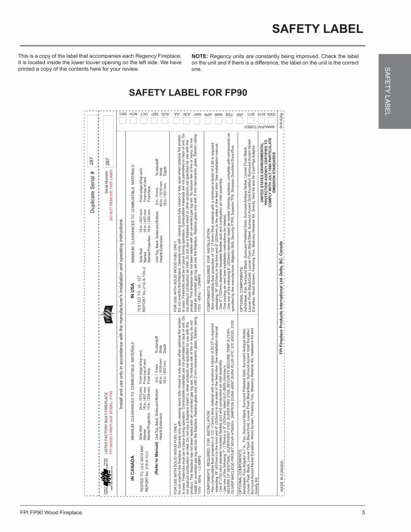
This is a copy of the label that accompanies each Regency Fireplace. It is located inside the lower louver opening on the left side. We have printed a copy of the contents here for your review.
safetY laBel
note: Regency units are constantly being improved. Check the label on the unit and if there is a difference, the label on the unit is the correct one.
LIS
TE
DFA
CT
OR
YB
UIL
TF
IRE
PLA
CE
FP
IW
OO
DF
IRE
PLA
CE
MO
DE
L:F
P90
DO
NO
TR
EM
OV
ET
HIS
LA
BE
L
Se
ria
lN
um
be
r
Duplic
ate
Serial#
MIN
IMU
MC
LE
AR
AN
CE
ST
OC
OM
BU
ST
IBLE
MA
TE
RIA
LS
Sid
eW
all
24
in./
610
mm
.F
rom
edge
oft
op
vent.
Mante
l18
in./
457
mm
.F
rom
top
ofv
ent.
Unit
Top,B
ack,S
ides
and
Bottom
0in
./0
mm
.To
sta
ndoff
Heart
hE
xte
nsio
n40
in./
1016
mm
.W
ide
18
in./
457
mm
.D
epth
Mante
lPro
jection
10
in./
254
mm
.F
rom
face.
MIN
IMU
MC
LE
AR
AN
CE
ST
OC
OM
BU
ST
IBLE
MA
TE
RIA
LS
Sid
eW
all
18
in./
457
mm
.F
rom
edge
oft
op
vent.
Mante
l18
in./
457
mm
Fro
mto
pofv
ent.
Unit
Top,B
ack,S
ides
and
Bottom
0in
./0
mm
.To
sta
ndoff
Heart
hE
xte
nsio
n40
in./
1016
mm
.W
ide
18
in./
457
mm
.D
epth
Mante
lPro
jection
10
in./
254
mm
.F
rom
face.
FP
IF
irep
lace
Pro
du
cts
Inte
rnati
on
alL
td.D
elt
a,B
C,C
an
ad
a
MANUFACTURED
918-4
24g
MA
DE
INC
AN
AD
A
20092010JANFEBMARAPRMAYJUNJULAUGSEPOCTNOVDEC
28
7
287
Insta
lland
use
only
inaccord
ance
with
the
manufa
ctu
rer's
insta
llation
and
opera
ting
instr
uctions.
TE
ST
ED
TO
:U
LC
-S610-M
87
RE
PO
RT
No.219-S
-10-2
TE
ST
ED
TO
:U
L-1
27
RE
PO
RT
No
.21
9-S
-10
b-2
INC
AN
AD
AIN
US
A
OP
TIO
NA
LC
OM
PO
NE
NT
S:
Ashdra
wer,
Flu
eA
dapto
r8-7
in.,
Fan,S
urr
ound
Bla
ck,S
urr
ound
Polis
hed
Gold
,S
urr
ound
Antique
Nic
kel,
Louver
Flu
sh
Bla
ck,Louver
Flu
sh
Bla
ck/G
old
,Louver
Flu
sh
Bla
ck/S
teel,
Surr
ound
AccentG
old
Excalib
ur,
Surr
ound
AccentN
ickelE
xcalib
ur,
Wood
Scre
en,F
inis
hin
gT
rim
,M
asonry
Reta
iner
Kit,H
eatw
ave
Kit
and
Gra
vity
Kit.
OP
TIO
NA
LC
OM
PO
NE
NT
S:
Ashdra
wer,
Fan,S
urr
ound
Bla
ck,S
urr
ound
Polis
hed
Gold
,S
urr
ound
Antique
Nic
kel,
Louver
Flu
sh
Bla
ck,
Louver
Flu
sh
Bla
ck/G
old
,Louver
Flu
sh
Bla
ck/S
teel,
Surr
ound
AccentG
old
Excalib
ur,
Surr
ound
AccentN
ickel
Excalib
ur,
Wood
Scre
en,F
inis
hin
gT
rim
,M
asonry
Reta
iner
Kit,G
ravity
VentK
itand
Air
CoolP
ipe
Adapto
r.
CO
MP
ON
EN
TS
RE
QU
IRE
DF
OR
INS
TA
LLA
TIO
N:
-N
on-c
om
bustible
floor
pro
tection
of1/2
”(1
3m
m)
thic
km
ate
rialw
ith
am
inim
um
k-f
acto
rof20.0
7is
required
exte
ndin
g18”
(457m
m)
toth
efr
ontand
8”
(203m
m)
toth
esid
es
ofth
efe
ed
door.
See
insta
llation
manual.
-U
se
6”
(152
mm
)dia
mete
rin
sula
ted
flexib
leductand
com
bustion
air
inle
tassem
bly
.-
Use
one
ofth
efo
llow
ing
7”
(178m
m)
or
8”
(203m
m)
liste
dU
LC
-S629
chim
ney’s
:S
ELK
IRK
CF
SE
NT
INA
L,S
UP
ER
VE
NT
2100,S
UP
ER
PR
O2100,S
EC
UR
ITY
SE
CU
RE
TE
MP
S-2
100+
,
OLIV
ER
MA
CLE
OD
PR
OJE
TN
OV
AH
T6000+
,S
IMP
SO
ND
UR
A-V
EN
TD
UR
AP
LU
SH
TC
,IC
CE
XC
EL
2100.
CO
MP
ON
EN
TS
RE
QU
IRE
DF
OR
INS
TA
LLA
TIO
N:
-N
on-c
om
bustible
floor
pro
tection
of1/2
”(1
3m
m)
thic
km
ate
rialw
ith
am
inim
um
k-f
acto
rof0.8
4is
required
exte
ndin
g18”
(457m
m)
toth
efr
ontand
8”
(203m
m)
toth
esid
es
ofth
efe
ed
door.
See
insta
llation
manual.
-U
se
6”
(152m
m)
dia
mete
rin
sula
ted
flexib
leductand
com
bustion
air
inle
tassem
bly
.-
One
coolin
gair
vent(s
ee
insta
llation
instr
uctions
for
deta
ils).
-U
se
one
ofth
efo
llow
ing
8”
(203m
m)
dia
mete
rlis
ted
air
coole
dchim
ney
syste
ms,com
ple
tew
ith
com
ponents
as
specifie
dby
the
manufa
ctu
rer:
Maje
stic
SK
8,S
ecurity
FT
F8,S
uperior
TF
8,S
impson
Dura
VentD
ura
-Plu
s.
FO
RU
SE
WIT
HS
OLID
WO
OD
FU
EL
ON
LY.
Do
notoverf
ire
the
fire
pla
ce.O
pera
teonly
with
vie
win
gdoors
fully
clo
sed
or
fully
open
when
optionalfire
scre
en
isused.F
irebricks
mustbe
inpla
ce
during
opera
tion.C
om
bustible
mate
rials
are
notperm
itte
don
face
ofunit.D
onotobstr
uctcom
bustion
air
inle
t.D
onotuse
afire
pla
ce
insert
or
oth
er
pro
ducts
notspecifie
dfo
ruse
with
this
pro
duct.
This
fire
pla
ce
has
notbeen
teste
dw
ith
an
unvente
dgas
log
set.
To
reduce
risk
offire
or
inju
ry,do
not
insta
llan
unvente
dgas
log
setin
toth
efire
pla
ce.R
epla
ce
gla
ss
only
with
5m
mneocera
mic
gla
ss.E
lectr
icra
ting.
115V
-60H
z-
1.2
AM
PS
(Re
fer
toM
an
ua
l)
2011
UN
ITE
DS
TA
TE
SE
NV
IRO
NM
EN
TA
LP
RO
TE
CT
ION
AG
EN
CY
CE
RT
IFIE
DT
OC
OM
PLY
WIT
HJU
LY
1990
PA
RT
ICU
LA
TE
EM
ISS
ION
STA
ND
AR
DS
FPI FP90 Wood Fireplace6
INS
TALL
ATIO
Ninstallation
product details
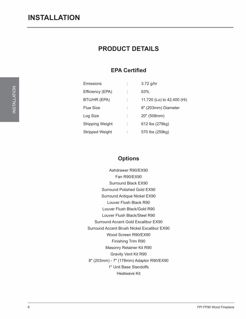
epa certified
Emissions : 3.72 g/hr Efficiency (EPA) : 63%
BTU/HR (EPA) : 11,720 (Lo) to 42,400 (Hi)
Flue Size : 8" (203mm) Diameter Log Size : 20" (508mm)
Shipping Weight : 612 lbs (278kg) Stripped Weight : 570 lbs (259kg)
options
Ashdrawer R90/EX90Fan R90/EX90
Surround Black EX90Surround Polished Gold EX90Surround Antique Nickel EX90
Louver Flush Black R90Louver Flush Black/Gold R90Louver Flush Black/Steel R90
Surround Accent Gold Excalibur EX90Surround Accent Brush Nickel Excalibur EX90
Wood Screen R90/EX90Finishing Trim R90
Masonry Retainer Kit R90Gravity Vent Kit R90
8" (203mm) - 7" (178mm) Adaptor R90/EX901" Unit Base Standoffs
Heatwave Kit
FPI FP90 Wood Fireplace 7
INS
TALLAT
ION
installation
6) Use solid fuel only. DO NOT use artificial logs containing petroleum products, chemical chimney cleaners, gas logs, gas lighters, salt contaminated wood or flame colorants in your fireplace. When using compressed sawdust logs use only at 1/3 capacity since these get very hot and expand.
7) DO NOT use charcoal or coal under any circumstances.
8) NEVER use gasoline, gasoline-type lantern
fuel, kerosene, charcoal lighter fluid, or any liquid to start or “freshen up” a fire in this fireplace. Keep any flammable liquid a safe distance from the fireplace.
9) Ashes should be placed in a metal container with a tight-fitting lid. The closed container of ashes should be placed on a non-combustible floor or on the ground, well away from all combustible materials, pending final disposal. If the ashes are disposed of by burial in soil or otherwise locally dispersed, they should be retained in the closed container until all cinders have thoroughly cooled.
10) WarninG: only operate fireplace with doors fully open when optional fire screen is used.
11) neVer leave children unattended when there is a fire burning in the fireplace.
12) Allow the fireplace to cool before servicing. Always shut-off any electricity to the fireplace while working on it. This will prevent any possible electrical shock.
13) regency is not responsible for any smoking or related problems that may result from the lack of adequate combustion air. it is the responsibility of the installer to ensure that adequate combustion air has been provided for the fireplace.
read Before You installtHe reGencY HiGH
efficiencY epa certified fireplace
This installation manual will enable you to make a safe, efficient and dependable installation of your fireplace and chimney system. Please read and understand these instructions before beginning your installation.
Do not alter or modify the fireplace or its components under any circumstances. Any modification or alteration of the fireplace system, including but not limited to the fireplace, chimney components and accessories, may void the warranty, listing and approvals of this system and could result in an unsafe and potentially dangerous installation. please retain tHis Manual for future reference.
iMportant: please read and follow these rules for safety. 1) Before starting your fireplace installation,
read these installation instructions carefully to be sure you understand them in their entirety. Failure to follow them could cause a fireplace malfunction resulting in serious injury and/or property damage.
2) Always check with your local building department, fire department and local authorities prior to installation to determine the need to obtain a permit.
3) This model fireplace must be installed with one of the chimney systems listed in the Chimney Section in this manual. These systems are intended for use as a residential type appliance. The chimney must always vent to the outside of the building.
4) WarninG: tHis fireplace Has not Been tested WitH an unVented Gas loG set. to reduce risK of fire or inJurY, do not install an unVented Gas loG set into tHe fireplace.
5) To ensure a safe fireplace system and to prevent the build-up of soot and creosote, inspect and clean the fireplace and chimney prior to use and periodically during the heating season.
14) FPI Fireplace Products International Ltd. does not warranty “smoke-free” operation nor are we responsible for inadequate system draft caused by mechanical systems, general construction conditions, inadequate chimney heights, adverse wind conditions and/or unusual environmental factors or conditions beyond our control.
15) iMportant: Check with your local building department as to the requirements of sealing any penetrations to the exterior. This will ensure that the integrity of the building is intact.
16) do not use a fireplace insert or any other product not specified by Regency for use with this fireplace.
17) neVer, under any circumstances, install a fireplace, chimney component or any accessories, supplied by Regency, that have visible or suspected physical damage as a result of handling or transportation. These items should be inspected by a Regency dealer or qualified factory representative to ensure safe condition. When in doubt, consult your Regency dealer.
18) It is recommended that power is supplied
to the terminal block of the unit to allow for the installation of blower components now or at a future date.
emissions from burning wood or gas could contain chemicals known to the state of california to cause cancer, birth defects or other reproductive harm.
FPI FP90 Wood Fireplace8
INS
TALL
ATIO
N
38"
43- 5/8"
14- 5/8" 13-3/8"
28"
9-5/8"
25"
15"
4-3/4"
50- 1/2"
(1283mm)
42- 5/8"
3-5/8"
1-3/8"
7-7/8"
29-1/8"
31"
37-3/8"(1083mm)
(92mm)
(121mm)(965mm)
(1108mm)
(371mm) (371mm)
(949mm)
(787mm)
(740mm)
(200mm)
(35mm)
(244mm)
(381mm)
(635mm)
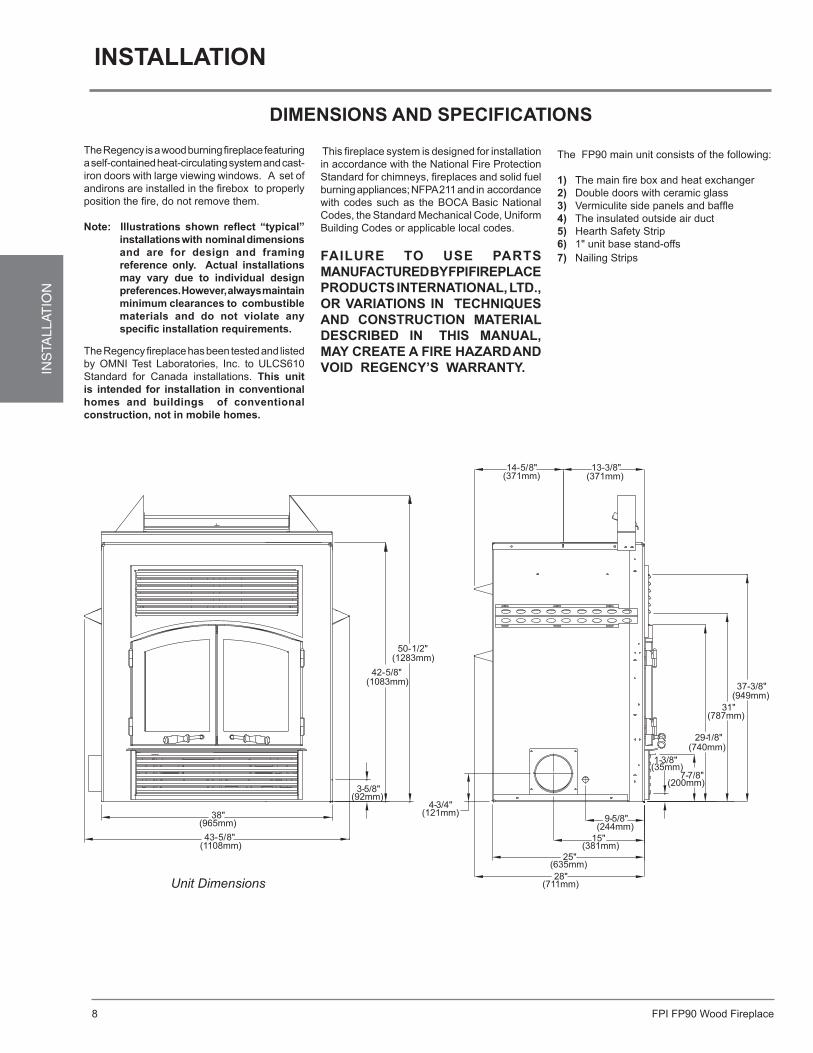
(711mm)Unit Dimensions
The Regency is a wood burning fireplace featuring a self-contained heat-circulating system and cast-iron doors with large viewing windows. A set of andirons are installed in the firebox to properly position the fire, do not remove them. note: illustrations shown reflect “typical”
installations with nominal dimensions and are for design and framing reference only. actual installations may vary due to individual design preferences. However, always maintain minimum clearances to combustible materials and do not violate any specific installation requirements.
diMensions and specifications
This fireplace system is designed for installation in accordance with the National Fire Protection Standard for chimneys, fireplaces and solid fuel burning appliances; NFPA 211 and in accordance with codes such as the BOCA Basic National Codes, the Standard Mechanical Code, Uniform Building Codes or applicable local codes.
failure to use parts Manufactured BY fpi fireplace products international, ltd., or Variations in tecHniQues and construction Material descriBed in tHis Manual, MaY create a fire HaZard and Void reGencY’s WarrantY.
The FP90 main unit consists of the following:
1) The main fire box and heat exchanger 2) Double doors with ceramic glass 3) Vermiculite side panels and baffle4) The insulated outside air duct5) Hearth Safety Strip6) 1" unit base stand-offs
installation
The Regency fireplace has been tested and listed by OMNI Test Laboratories, Inc. to ULCS610 Standard for Canada installations. this unit is intended for installation in conventional homes and buildings of conventional construction, not in mobile homes.
7) Nailing Strips
FPI FP90 Wood Fireplace 9
INS
TALLAT
ION
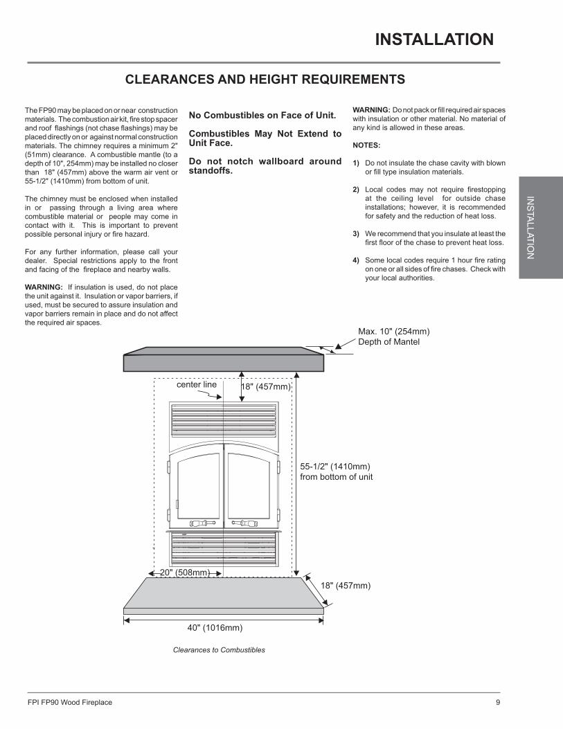
no combustibles on face of unit.
combustibles May not extend to unit face.
do not notch wallboard around standoffs.
The FP90 may be placed on or near construction materials. The combustion air kit, fire stop spacer and roof flashings (not chase flashings) may be placed directly on or against normal construction materials. The chimney requires a minimum 2" (51mm) clearance. A combustible mantle (to a depth of 10", 254mm) may be installed no closer than 18" (457mm) above the warm air vent or 55-1/2" (1410mm) from bottom of unit.
The chimney must be enclosed when installed in or passing through a living area where combustible material or people may come in contact with it. This is important to prevent possible personal injury or fire hazard.
For any further information, please call your dealer. Special restrictions apply to the front and facing of the fireplace and nearby walls. WarninG: If insulation is used, do not place the unit against it. Insulation or vapor barriers, if used, must be secured to assure insulation and vapor barriers remain in place and do not affect the required air spaces.
WarninG: Do not pack or fill required air spaces with insulation or other material. No material of any kind is allowed in these areas.
notes:
1) Do not insulate the chase cavity with blown or fill type insulation materials.
2) Local codes may not require firestopping at the ceiling level for outside chase installations; however, it is recommended for safety and the reduction of heat loss.
3) We recommend that you insulate at least the
first floor of the chase to prevent heat loss.
4) Some local codes require 1 hour fire rating on one or all sides of fire chases. Check with your local authorities.
clearances and HeiGHt reQuireMents
installation
Clearances to Combustibles
Max. 10" (254mm)Depth of Mantel
center line 18" (457mm)
55-1/2" (1410mm)from bottom of unit
18" (457mm)20" (508mm)
40" (1016mm)
FPI FP90 Wood Fireplace10
INS
TALL
ATIO
N
Building structures cannot encroach on chase
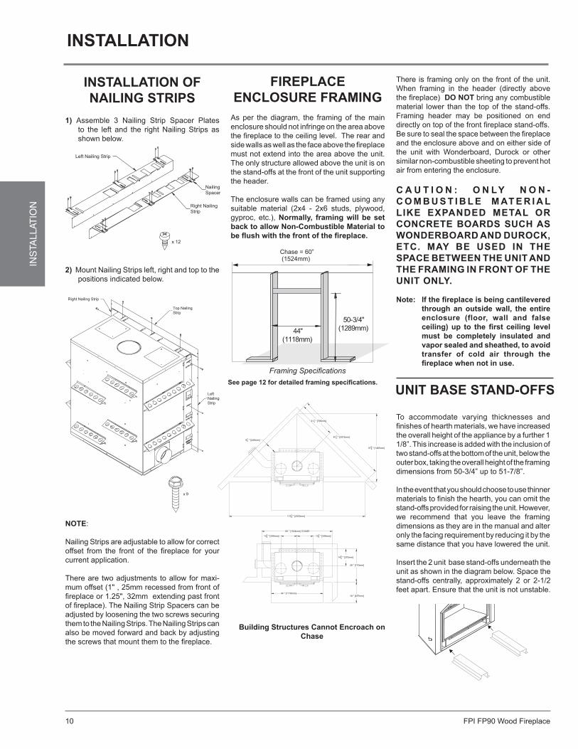
installation of nailinG strips
1) Assemble 3 Nailing Strip Spacer Plates to the left and the right Nailing Strips as shown below.
Left Nailing Strip
Nailing StripSpacer Plates
Right NailingStrip
x 12
Right Nailing Strip
Top NailingStrip
LeftNailingStrip
x 9
2) Mount Nailing Strips left, right and top to the positions indicated below.
note:
Nailing Strips are adjustable to allow for correct offset from the front of the fireplace for your current application.
There are two adjustments to allow for maxi-mum offset (1" , 25mm recessed from front of fireplace or 1.25", 32mm extending past front of fireplace). The Nailing Strip Spacers can be adjusted by loosening the two screws securing them to the Nailing Strips. The Nailing Strips can also be moved forward and back by adjusting the screws that mount them to the fireplace.
fireplace enclosure fraMinG
As per the diagram, the framing of the main enclosure should not infringe on the area above the fireplace to the ceiling level. The rear and side walls as well as the face above the fireplace must not extend into the area above the unit. The only structure allowed above the unit is on the stand-offs at the front of the unit supporting the header.
The enclosure walls can be framed using any suitable material (2x4 - 2x6 studs, plywood, gyproc, etc.), normally, framing will be set back to allow non-combustible Material to be flush with the front of the fireplace.
There is framing only on the front of the unit. When framing in the header (directly above the fireplace) do not bring any combustible material lower than the top of the stand-offs. Framing header may be positioned on end directly on top of the front fireplace stand-offs. Be sure to seal the space between the fireplace and the enclosure above and on either side of the unit with Wonderboard, Durock or other similar non-combustible sheeting to prevent hot air from entering the enclosure.
c a u t i o n : o n lY n o n -c o M B u s t i B l e M at e r i a l liKe eXpanded Metal or concrete Boards sucH as WonderBoard and durocK, etc. MaY Be used in tHe space BetWeen tHe unit and tHe fraMinG in front of tHe unit onlY.
note: if the fireplace is being cantilevered through an outside wall, the entire enclosure (floor, wall and false ceiling) up to the first ceiling level must be completely insulated and vapor sealed and sheathed, to avoid transfer of cold air through the fireplace when not in use.
Framing Specifications
installation
unit Base stand-offs
To accommodate varying thicknesses and finishes of hearth materials, we have increased the overall height of the appliance by a further 1 1/8”. This increase is added with the inclusion of two stand-offs at the bottom of the unit, below the outer box, taking the overall height of the framing dimensions from 50-3/4” up to 51-7/8”.
In the event that you should choose to use thinner materials to finish the hearth, you can omit the stand-offs provided for raising the unit. However, we recommend that you leave the framing dimensions as they are in the manual and alter only the facing requirement by reducing it by the same distance that you have lowered the unit.
Insert the 2 unit base stand-offs underneath the unit as shown in the diagram below. Space the stand-offs centrally, approximately 2 or 2-1/2 feet apart. Ensure that the unit is not unstable.
see page 12 for detailed framing specifications.
44 " [1118mm]
" [248mm]349
" [2930mm]83115
18 " [457mm]
" [370mm]8145
28 " [710mm]
" [1465mm]
" [2072mm]8121
8557
4131 " [795mm]
13 " [348mm]34
60 " [1524mm] CHASE
" [348mm]3413
FPI FP90 Wood Fireplace 11
INS
TALLAT
ION
Fire Stop FireStop
Straightrunfor 8"(203mm)Hot Air Duct
Unit projectsout flush with
non-combustible material
2 x 4 Framing 2 x 6 Framing
10"
2 x 6Wall with a
2 x 4 Header
Stud
84"
(213
7mm
)
50-3
/4"
(128
9mm
)
55-3
/4"
(141
6mm
) 42
-5/8
"(1
083m
m)
(254mm)
2 x 4Stud Wall
5"(127mm)wide sheet
metal strip under unit and hearth
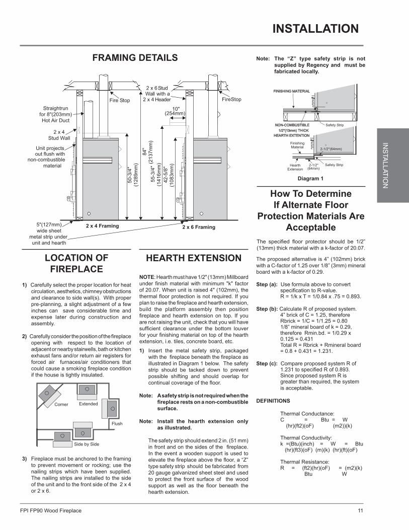
fraMinG details
location of fireplace
1) Carefully select the proper location for heat circulation, aesthetics, chimney obstructions and clearance to side wall(s). With proper pre-planning, a slight adjustment of a few inches can save considerable time and expense later during construction and assembly.
2) Carefully consider the position of the fireplace opening with respect to the location of adjacent or nearby stairwells, bath or kitchen exhaust fans and/or return air registers for forced air furnaces/air conditioners that could cause a smoking fireplace condition if the house is tightly insulated.
3) Fireplace must be anchored to the framing to prevent movement or rocking; use the nailing strips which have been supplied. The nailing strips are installed to the side of the unit and to the front side of the 2 x 4 or 2 x 6.
1) Insert the metal safety strip, packaged with the fireplace beneath the fireplace as illustrated in Diagram 1 below. The safety strip should be tacked down to prevent possible shifting and should overlap for continual coverage of the floor.
note: a safety strip is not required when the fireplace rests on a non-combustible surface.
note: install the hearth extension only
as illustrated.
The safety strip should extend 2 in. (51 mm) in front and on the sides of the fireplace. In the event a wooden support is used to elevate the fireplace above the floor, a “Z” type safety strip should be fabricated from 20 gauge galvanized sheet steel and used to protect the front surface of the wood support as well as the floor beneath the hearth extension.
FINISHING MATERIAL
NON-COMBUSTIBLE 1/2"(13mm) THICK
HEARTH EXTENTION
(64mm)
(64mm)
diagram 1
note: the “Z” type safety strip is not supplied by regency and must be fabricated locally.
The proposed alternative is 4” (102mm) brick with a C-factor of 1.25 over 1/8” (3mm) mineral board with a k-factor of 0.29.
step (a): Use formula above to convert specification to R-value. R = 1/k x T = 1/0.84 x .75 = 0.893.
step (b): Calculate R of proposed system. 4” brick of C = 1.25, therefore Rbrick = 1/C = 1/1.25 = 0.80 1/8” mineral board of k = 0.29, therefore Rmin.bd. = 1/0.29 x 0.125 = 0.431 Total R = Rbrick + Rmineral board = 0.8 + 0.431 = 1.231.
step (c): Compare proposed system R of 1.231 to specified R of 0.893. Since proposed system R is greater than required, the system is acceptable.
definitions
Thermal Conductance: C = Btu = W (hr)(ft2)(oF) (m2))(k)
Thermal Conductivity: k =(Btu)(inch) = W = Btu (hr)(ft3)(oF) (m)(k) (hr)(ft)(oF)
Thermal Resistance: R = (ft2)(hr)(oF) = (m2)(k) Btu W
installation
HeartH eXtension
note: Hearth must have 1/2" (13mm) Millboard under finish material with minimum "k" factor of 20.07. When unit is raised 4" (102mm), the thermal floor protection is not required. If you plan to raise the fireplace and hearth extension, build the platform assembly then position fireplace and hearth extension on top. If you are not raising the unit, check that you will have sufficient clearance under the bottom louver for your finishing material on top of the hearth extension, i.e. tiles, concrete board, etc.
How to determine if alternate floor
protection Materials are acceptable
The specified floor protector should be 1/2” (13mm) thick material with a k-factor of 20.07.
FPI FP90 Wood Fireplace12
INS
TALL
ATIO
N
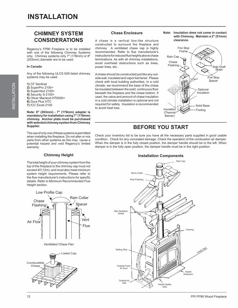
Ventilated Chase Pan
Before You start Check your inventory list to be sure you have all the necessary parts supplied in good usable condition. Check for any concealed damage. Check the operation of the combustion air damper. When the damper is in the fully closed position, the damper handle should be to the left. When damper is in the fully open position, the damper handle must be in the right position.
installation coMponents diaGraMinstallation components
note: insulation does not come in contact with chimney. Maintain a 2" (51mm) clearance.
installation
cHiMneY sYsteM considerations
Regency’s FP90 Fireplace is to be installed with one of the following Chimney Systems only. Chimney systems only 7" (178mm) or 8" (203mm) diameter are to be used.
in canada
Any of the following ULCS 629 listed chimney systems may be used:
1) CF Sentinal 2) SuperPro 2100+ 3) SuperVent 2100+4) Security S-2100+5) Oliver Macleod HT6000+6) Dura Plus HTC7) ICC Excel 2100
note: 8" (203mm) - 7" (178mm) adapter is mandatory for installation using 7" (178mm) chimney. anchor plate must be purchased with selected chimney system from chimney supplier.
The use of only one of these systems is permitted when installing the fireplace. Do not alter or mix parts from other systems as this may cause a potential hazard and void Regency’s limited warranty.
chimney Height
The total height of your chimney system from the top of the fireplace to the chimney cap must not exceed 40'(12m), and must also meet minimum system height requirements. Please refer to the flue manufacturer's instructions for specific details. Refer to Minimum Recommended Flue Height section.
chase enclosure
A chase is a vertical box-like structure constructed to surround the fireplace and chimney. A ventilated chase cap is highly recommended. Refer to flue manufacturer's instructions for reduced flue heights above chase terminations. As with all chimney installations, avoid overhead obstructions such as trees, power lines, etc.
A chase should be constructed just like any out-side wall, insulated and vapor barriered. Please check with local building authorities. In a cold climate, we recommend the base of the chase be insulated between the solid continuous floor beneath the fireplace and the chase bottom. If used, the value and amount of chase insulation in a cold climate installation is optional and not required for safety. Insulation is recommended to avoid heat loss.
Inside Wall
Rain Cap
Storm Collar
Roof Flashing
Attic RadiationShield
Nailing Strip
Outside FreshAir Duct
HearthExtension
Hearth SafetyStrip
Outside AirInlet
Framing

FPI FP90 Wood Fireplace 13
INS
TALLAT
ION
installation MeasureMents / fraMinG details
installation
3" (76mm)
STAND-OFF
2x4 FRAMING
FRONT OF UNIT ONLYCOMBUSTION AIR
TO OUTSIDE
38"
(965mm)
19"
(483mm)
30"
(762mm)
60" (1524mm) WIDE INSIDE MIN.
UNIT TO BE CENTERE
NOTE:
FRAMING TO BE AGAI
STAND-OFFS ONLY
11"
(279mm)
D
NST
24"
(610mm)
VENT TO OUTSIDE
COMBUSTION AIR
11"
(280mm)
HEARTH MUST HAVE 1/2" (127mm)
MILLBOARD UNDER FINISH MATERIAL
WITH MIN. "K" FACTOR OF 20.07
50 3/4"
(1289mm)
44"
(1118mm)
40"
(1016mm)
18"
(457mm)
46"(1168mm)
MIN.
11"
(280mm)
18"
(457mm)
2X4, 2X6, 2X8 ONEND
60"(1524mm)
WIDE INSIDE CHASE MIN.
10"
(254mm)
84" (2134mm)
CEILING
NOTES:1) CHASE MUST BE 60" (1524mm) WIDE INSIDE AND UNIT TO BE CENTERED IN OPENING.2) MANTEL MIN. HEIGHT OF 18" (457mm) FROM TOP OF LOUVER OPENING TO UNDERNEATH MANTEL or 55 1/2" (1410mm) FROM BOTTOM OF UNIT.3) MUST HAVE NON-COMBUSTIBLE MATERIAL EXTENDING 11" (280mm) ON EITHER SIDE AND 9" (229mm) ON TOP. 3/8" (10mm) THICK FINISHING
MATERIAL TO BE INSTALLED ON TOP OF THIS.4) FRAMING IS SLIGHTLY LARGER THAN UNIT DIMENSIONS TO ALLOW FOR EASIER INSTALLATION (50 3/4", 1289mm H x 44", 1118mm W)5) MUST MAINTAIN A MIN. OF 46" (1168mm) FROM TOP OF LOUVER OPENING TO FINISHED CEILING.6) MUST MAINTAIN A MIN. OF 24" (610mm) TO SIDE WALL FROM THE EDGE OF THE TOP LOUVER OPENING.7) HEARTH MUST BE A MIN. OF 40" (1016mm) WIDE x 18" (457mm) deep and 1/2" (127MM) THICK.
2x4
2x4
FPI FP90 Wood Fireplace14
INS
TALL
ATIO
N
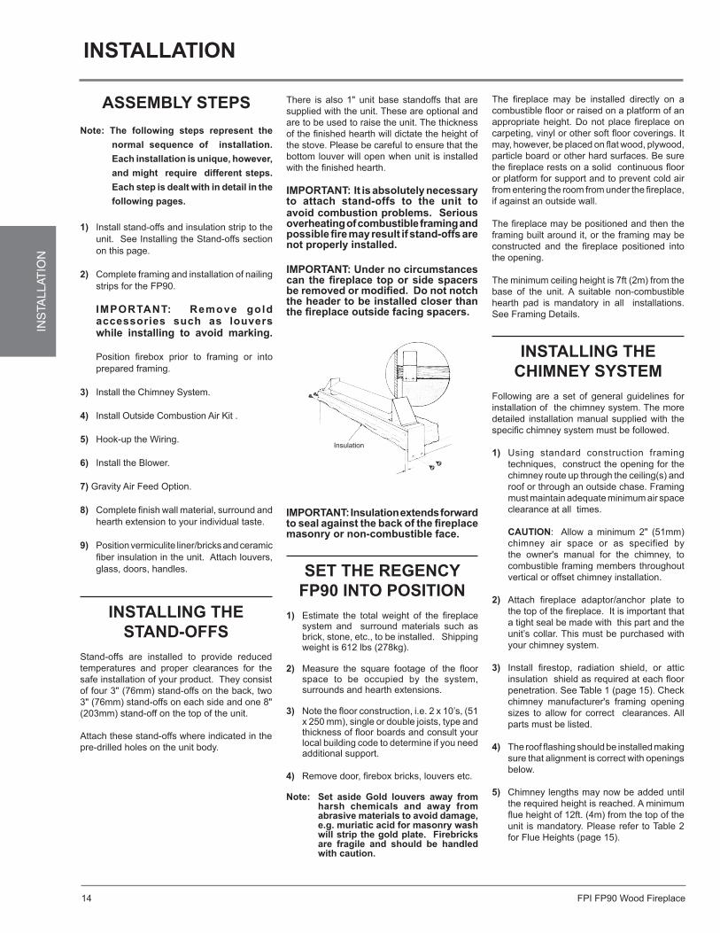
There is also 1" unit base standoffs that are supplied with the unit. These are optional and are to be used to raise the unit. The thickness of the finished hearth will dictate the height of the stove. Please be careful to ensure that the bottom louver will open when unit is installed with the finished hearth.
iMportant: it is absolutely necessary to attach stand-offs to the unit to avoid combustion problems. serious overheating of combustible framing and possible fire may result if stand-offs are not properly installed.
iMportant: under no circumstances can the fireplace top or side spacers be removed or modified. do not notch the header to be installed closer than the fireplace outside facing spacers.
The fireplace may be installed directly on a combustible floor or raised on a platform of an appropriate height. Do not place fireplace on carpeting, vinyl or other soft floor coverings. It may, however, be placed on flat wood, plywood, particle board or other hard surfaces. Be sure the fireplace rests on a solid continuous floor or platform for support and to prevent cold air from entering the room from under the fireplace, if against an outside wall.
The fireplace may be positioned and then the framing built around it, or the framing may be constructed and the fireplace positioned into the opening.
The minimum ceiling height is 7ft (2m) from the base of the unit. A suitable non-combustible hearth pad is mandatory in all installations. See Framing Details.
installinG tHe cHiMneY sYsteM
Following are a set of general guidelines for installation of the chimney system. The more detailed installation manual supplied with the specific chimney system must be followed.
1) Using standard construction framing techniques, construct the opening for the chimney route up through the ceiling(s) and roof or through an outside chase. Framing must maintain adequate minimum air space clearance at all times.
caution: Allow a minimum 2" (51mm)
chimney air space or as specified by the owner's manual for the chimney, to combustible framing members throughout vertical or offset chimney installation.
2) Attach fireplace adaptor/anchor plate to the top of the fireplace. It is important that a tight seal be made with this part and the unit’s collar. This must be purchased with your chimney system.
3) Install firestop, radiation shield, or attic insulation shield as required at each floor penetration. See Table 1 (page 15). Check chimney manufacturer's framing opening sizes to allow for correct clearances. All parts must be listed.
4) The roof flashing should be installed making sure that alignment is correct with openings below.
5) Chimney lengths may now be added until the required height is reached. A minimum flue height of 12ft. (4m) from the top of the unit is mandatory. Please refer to Table 2 for Flue Heights (page 15).
installinG tHe stand-offs
Stand-offs are installed to provide reduced temperatures and proper clearances for the safe installation of your product. They consist of four 3" (76mm) stand-offs on the back, two 3" (76mm) stand-offs on each side and one 8" (203mm) stand-off on the top of the unit.
Attach these stand-offs where indicated in the pre-drilled holes on the unit body.
iMportant: insulation extends forward to seal against the back of the fireplace masonry or non-combustible face.
set tHe reGencY fp90 into position
1) Estimate the total weight of the fireplace system and surround materials such as brick, stone, etc., to be installed. Shipping weight is 612 lbs (278kg).
2) Measure the square footage of the floor space to be occupied by the system, surrounds and hearth extensions.
3) Note the floor construction, i.e. 2 x 10’s, (51 x 250 mm), single or double joists, type and thickness of floor boards and consult your local building code to determine if you need additional support.
4) Remove door, firebox bricks, louvers etc. note: set aside Gold louvers away from
harsh chemicals and away from abrasive materials to avoid damage, e.g. muriatic acid for masonry wash will strip the gold plate. firebricks are fragile and should be handled with caution.
installation
asseMBlY stepsnote: the following steps represent the
normal sequence of installation. each installation is unique, however, and might require different steps. each step is dealt with in detail in the following pages.
1) Install stand-offs and insulation strip to the unit. See Installing the Stand-offs section on this page.
2) Complete framing and installation of nailing strips for the FP90.
iMportant: remove gold accessories such as louvers while installing to avoid marking.
Position firebox prior to framing or into
prepared framing.
3) Install the Chimney System.
4) Install Outside Combustion Air Kit .
5) Hook-up the Wiring.
6) Install the Blower.
7) Gravity Air Feed Option.
8) Complete finish wall material, surround and hearth extension to your individual taste.
9) Position vermiculite liner/bricks and ceramic fiber insulation in the unit. Attach louvers, glass, doors, handles.
FPI FP90 Wood Fireplace 15
INS
TALLAT
ION
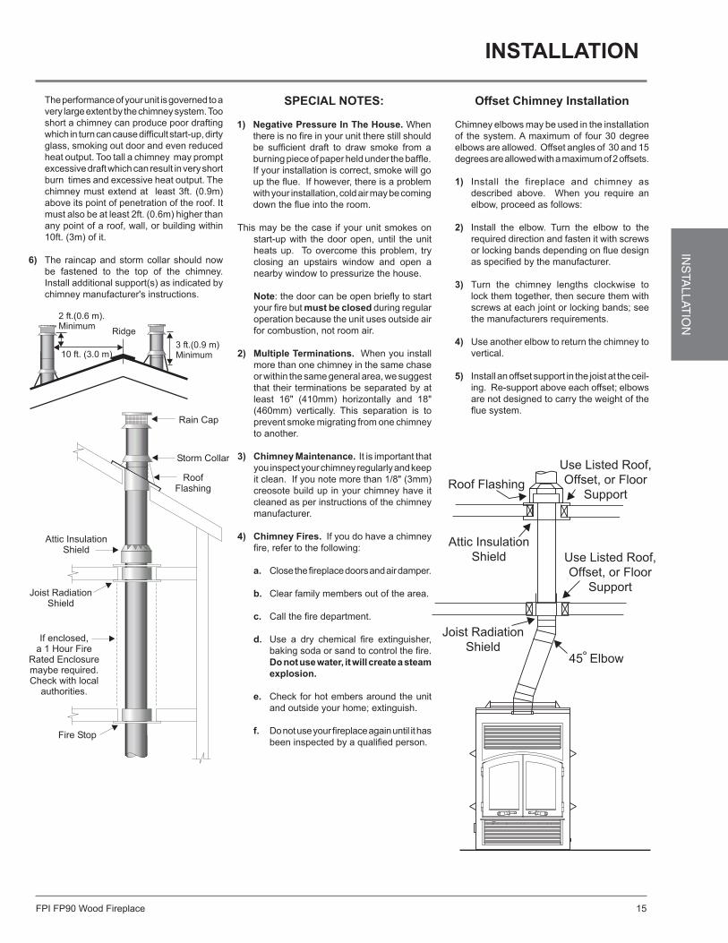
The performance of your unit is governed to a very large extent by the chimney system. Too short a chimney can produce poor drafting which in turn can cause difficult start-up, dirty glass, smoking out door and even reduced heat output. Too tall a chimney may prompt excessive draft which can result in very short burn times and excessive heat output. The chimney must extend at least 3ft. (0.9m) above its point of penetration of the roof. It must also be at least 2ft. (0.6m) higher than any point of a roof, wall, or building within 10ft. (3m) of it.
6) The raincap and storm collar should now be fastened to the top of the chimney. Install additional support(s) as indicated by chimney manufacturer's instructions.
offset chimney installation
Chimney elbows may be used in the installation of the system. A maximum of four 30 degree elbows are allowed. Offset angles of 30 and 15 degrees are allowed with a maximum of 2 offsets. 1) Install the fireplace and chimney as
described above. When you require an elbow, proceed as follows:
2) Install the elbow. Turn the elbow to the required direction and fasten it with screws or locking bands depending on flue design as specified by the manufacturer.
3) Turn the chimney lengths clockwise to lock them together, then secure them with screws at each joint or locking bands; see the manufacturers requirements.
4) Use another elbow to return the chimney to vertical.
5) Install an offset support in the joist at the ceil-ing. Re-support above each offset; elbows are not designed to carry the weight of the flue system.
special notes:
1) negative pressure in the House. When there is no fire in your unit there still should be sufficient draft to draw smoke from a burning piece of paper held under the baffle. If your installation is correct, smoke will go up the flue. If however, there is a problem with your installation, cold air may be coming down the flue into the room.
installation
This may be the case if your unit smokes on start-up with the door open, until the unit heats up. To overcome this problem, try closing an upstairs window and open a nearby window to pressurize the house. note: the door can be open briefly to start your fire but must be closed during regular operation because the unit uses outside air for combustion, not room air.
2) Multiple terminations. When you install more than one chimney in the same chase or within the same general area, we suggest that their terminations be separated by at least 16" (410mm) horizontally and 18" (460mm) vertically. This separation is to prevent smoke migrating from one chimney to another.
3) chimney Maintenance. It is important that you inspect your chimney regularly and keep it clean. If you note more than 1/8" (3mm) creosote build up in your chimney have it cleaned as per instructions of the chimney manufacturer.
4) chimney fires. If you do have a chimney fire, refer to the following:
a. Close the fireplace doors and air damper.
b. Clear family members out of the area.
c. Call the fire department.
d. Use a dry chemical fire extinguisher, baking soda or sand to control the fire. do not use water, it will create a steam explosion.
e. Check for hot embers around the unit and outside your home; extinguish.
f. Do not use your fireplace again until it has been inspected by a qualified person.
45 Elbow
Joist Radiation Shield
Attic Insulation Shield Use Listed Roof,
Offset, or Floor Support
Roof FlashingUse Listed Roof, Offset, or Floor
Support
FPI FP90 Wood Fireplace16
INS
TALL
ATIO
N
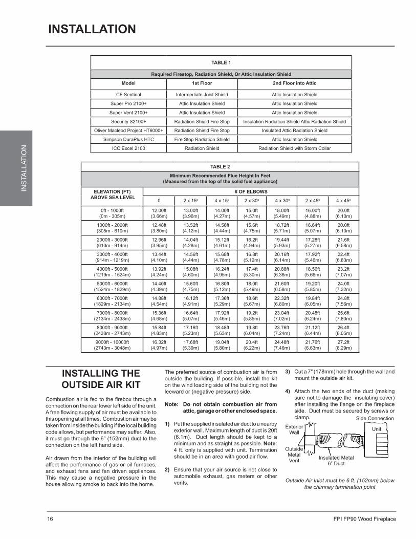
installinG tHe outside air Kit
Combustion air is fed to the firebox through a connection on the rear lower left side of the unit. A free flowing supply of air must be available to this opening at all times. Combustion air may be taken from inside the building if the local building code allows, but performance may suffer. Also, it must go through the 6" (152mm) duct to the connection on the left hand side.
Air drawn from the interior of the building will affect the performance of gas or oil furnaces, and exhaust fans and fan driven appliances. This may cause a negative pressure in the house allowing smoke to back into the home.
Outside Air Inlet must be 6 ft. (152mm) below the chimney termination point
Insulated Metal6” Duct
ExteriorWall
OutsideMetalVent
Side Connection
Unit
The preferred source of combustion air is from outside the building. If possible, install the kit on the wind loading side of the building not the leeward or (negative pressure) side.
note: do not obtain combustion air from attic, garage or other enclosed space.
1) Put the supplied insulated air duct to a nearby exterior wall. Maximum length of duct is 20ft (6.1m). Duct length should be kept to a minimum and as straight as possible. note: 4 ft. only is supplied with unit. Termination should be in an area with good air flow.
2) Ensure that your air source is not close to automobile exhaust, gas meters or other vents.
3) Cut a 7" (178mm) hole through the wall and mount the outside air kit.
4) Attach the two ends of the duct (making sure not to damage the insulating cover) after installing the flange on the fireplace side. Duct must be secured by screws or clamp.
installation
taBle 1
required firestop, radiation shield, or attic insulation shield
Model 1st floor 2nd floor into attic
CF Sentinal Intermediate Joist Shield Attic Insulation Shield
Super Pro 2100+ Attic Insulation Shield Attic Insulation Shield
Super Vent 2100+ Attic Insulation Shield Attic Insulation Shield
Security S2100+ Radiation Shield Fire Stop Insulation Radiation Shield Attic Radiation Shield
Oliver Macleod Project HT6000+ Radiation Shield Fire Stop Insulated Attic Radiation Shield
Simpson DuraPlus HTC Fire Stop Radiation Shield Attic Insulation Shield
ICC Excel 2100 Radiation Shield Radiation Shield with Storm Collar
taBle 2
Minimum recommended flue Height in feet(Measured from the top of the solid fuel appliance)
eleVation (ft) aBoVe sea leVel
# of elBoWs
0 2 x 15o 4 x 15o 2 x 30o 4 x 30o 2 x 45o 4 x 45o
0ft - 1000ft(0m - 305m)
12.00ft (3.66m)
13.00ft (3.96m)
14.00ft (4.27m)
15.0ft (4.57m)
18.00ft (5.49m)
16.00ft (4.88m)
20.0ft (6.10m)
1000ft - 2000ft(305m - 610m)
12.48ft (3.80m)
13.52ft (4.12m)
14.56ft (4.44m)
15.6ft (4.75m)
18.72ft (5.71m)
16.64ft (5.07m)
20.0ft (6.10m)
2000ft - 3000ft(610m - 914m)
12.96ft (3.95m)
14.04ft (4.28m)
15.12ft (4.61m)
16.2ft (4.94m)
19.44ft (5.93m)
17.28ft (5.27m)
21.6ft (6.58m)
3000ft - 4000ft(914m - 1219m)
13.44ft (4.10m)
14.56ft (4.44m)
15.68ft (4.78m)
16.8ft (5.12m)
20.16ft (6.14m)
17.92ft (5.46m)
22.4ft (6.83m)
4000ft - 5000ft(1219m - 1524m)
13.92ft (4.24m)
15.08ft (4.60m)
16.24ft (4.95m)
17.4ft (5.30m)
20.88ft (6.36m)
18.56ft (5.66m)
23.2ft (7.07m)
5000ft - 6000ft(1524m - 1829m)
14.40ft (4.39m)
15.60ft (4.75m)
16.80ft (5.12m)
18.0ft (5.49m)
21.60ft (6.58m)
19.20ft (5.85m)
24.0ft (7.32m)
6000ft - 7000ft(1829m - 2134m)
14.88ft (4.54m)
16.12ft (4.91m)
17.36ft (5.29m)
18.6ft (5.67m)
22.32ft (6.80m)
19.84ft (6.05m)
24.8ft (7.56m)
7000ft - 8000ft(2134m - 2438m)
15.36ft(4.68m)
16.64ft (5.07m)
17.92ft (5.46m)
19.2ft (5.85m)
23.04ft (7.02m)
20.48ft (6.24m)
25.6ft (7.80m)
8000ft - 9000ft(2438m - 2743m)
15.84ft (4.83m)
17.16ft (5.23m)
18.48ft (5.63m)
19.8ft (6.04m)
23.76ft (7.24m)
21.12ft (6.44m)
26.4ft (8.05m)
9000ft - 10000ft(2743m - 3048m)
16.32ft (4.97m)
17.68ft (5.39m)
19.04ft (5.80m)
20.4ft (6.22m)
24.48ft (7.46m)
21.76ft (6.63m)
27.2ft (8.29m)
FPI FP90 Wood Fireplace 17
INS
TALLAT
ION
Plan View Jakel AX-2495 Blower
Angle View
Fan Transfer Plate
Right View
Front View
Fan 910-175 AX-3088 910-903 910-516
Ground
Neutral - from Fan
910-
811
Thermodisc 910-142 P60T12 Variable Switch 910-330
919-885
Power Chord 910-619
Ground
Hot
- to
Var
iabl
e S
witc
h
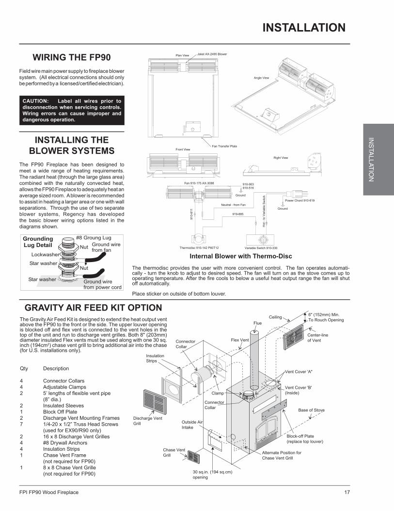
WirinG tHe fp90Field wire main power supply to fireplace blower system. (All electrical connections should only be performed by a licensed/certified electrician).
caution: label all wires prior to disconnection when servicing controls. Wiring errors can cause improper and dangerous operation.
installinG tHe BloWer sYsteMs
The FP90 Fireplace has been designed to meet a wide range of heating requirements. The radiant heat (through the large glass area) combined with the naturally convected heat, allows the FP90 Fireplace to adequately heat an average sized room. A blower is recommended to assist in heating a larger area or one with wall separations. Through the use of two separate blower systems, Regency has developed the basic blower wiring options listed in the diagrams shown.
GraVitY air feed Kit optionThe Gravity Air Feed Kit is designed to extend the heat output vent above the FP90 to the front or the side. The upper louver opening is blocked off and flex vent is connected to the vent holes in the top of the unit and run to discharge vent grilles. Both 8" (203mm) diameter insulated Flex vents must be used along with one 30 sq. inch (194cm2) chase vent grill to bring additional air into the chase (for U.S. installations only).
Qty Description
4 Connector Collars4 Adjustable Clamps2 5’ lengths of flexible vent pipe (8” dia.)2 Insulated Sleeves1 Block Off Plate2 Discharge Vent Mounting Frames7 1/4-20 x 1/2” Truss Head Screws (used for EX90/R90 only)2 16 x 8 Discharge Vent Grilles4 #8 Drywall Anchors4 Insulation Strips1 Chase Vent Frame (not required for FP90)1 8 x 8 Chase Vent Grille (not required for FP90)
Discharge Vent Grill
Chase Vent Grill
30 sq.in. (194 sq.cm) opening
Alternate Position for Chase Vent Grill
Block-off Plate(replace top louver)
Base of Stove
Vent Cover 'B'(Inside)
Vent Cover 'A"
Center-lineof Vent
6" (152mm) Min.To Rouch Opening
CeilingFlue
Flex Vent
Clamp
ConnectorCollar
ConnectorCollar
Outside AirIntake
Insulation Strips
installation
internal Blower with thermo-disc
The thermodisc provides the user with more convenient control. The fan operates automati-cally - turn the knob to adjust to desired speed. The fan will turn on as the stove comes up to operating temperature. After the fire cools to below a useful heat output range the fan will shut off automatically.
Place sticker on outside of bottom louver.
FPI FP90 Wood Fireplace18
INS
TALL
ATIO
N
Flex Vent
DischargeVent Grille
Discharge Vent Frame
ConnectingCollar
Clamp
FlexVent
Insulation Strips
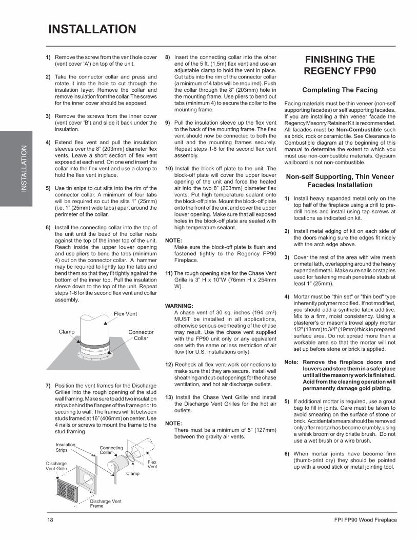
1) Remove the screw from the vent hole cover (vent cover 'A') on top of the unit.
2) Take the connector collar and press and rotate it into the hole to cut through the insulation layer. Remove the collar and remove insulation from the collar. The screws for the inner cover should be exposed.
3) Remove the screws from the inner cover (vent cover 'B') and slide it back under the insulation.
4) Extend flex vent and pull the insulation sleeves over the 8” (203mm) diameter flex vents. Leave a short section of flex vent exposed at each end. On one end insert the collar into the flex vent and use a clamp to hold the flex vent in place.
5) Use tin snips to cut slits into the rim of the connector collar. A minimum of four tabs will be required so cut the slits 1” (25mm) (i.e. 1” (25mm) wide tabs) apart around the perimeter of the collar.
6) Install the connecting collar into the top of the unit until the bead of the collar rests against the top of the inner top of the unit. Reach inside the upper louver opening and use pliers to bend the tabs (minimum 4) out on the connector collar. A hammer may be required to lightly tap the tabs and bend them so that they fit tightly against the bottom of the inner top. Pull the insulation sleeve down to the top of the unit. Repeat steps 1-6 for the second flex vent and collar assembly.
7) Position the vent frames for the Discharge Grilles into the rough opening of the stud wall framing. Make sure to add two insulation strips behind the flanges of the frame prior to securing to wall. The frames will fit between studs framed at 16” (406mm) on center. Use 4 nails or screws to mount the frame to the stud framing.
completing the facing
Facing materials must be thin veneer (non-self supporting facades) or self supporting facades. If you are installing a thin veneer facade the Regency Masonry Retainer Kit is recommended. All facades must be non-combustible such as brick, rock or ceramic tile. See Clearance to Combustible diagram at the beginning of this manual to determine the extent to which you must use non-combustible materials. Gypsum wallboard is not non-combustible.
non-self supporting, thin Veneer facades installation
1) Install heavy expanded metal only on the top half of the fireplace using a drill to pre-drill holes and install using tap screws at locations as indicated on kit.
2) Install metal edging of kit on each side of the doors making sure the edges fit nicely with the arch edge above.
3) Cover the rest of the area with wire mesh or metal lath, overlapping around the heavy expanded metal. Make sure nails or staples used for fastening mesh penetrate studs at least 1" (25mm).
4) Mortar must be "thin set" or "thin bed" type inherently polymer modified. If not modified, you should add a synthetic latex additive. Mix to a firm, moist consistency. Using a plasterer's or mason's trowel apply mortar 1/2" (13mm) to 3/4" (19mm) thick to prepared surface area. Do not spread more than a workable area so that the mortar will not set up before stone or brick is applied.
note: remove the fireplace doors and louvers and store them in a safe place until all the masonry work is finished. acid from the cleaning operation will permanently damage gold plating.
5) If additional mortar is required, use a grout bag to fill in joints. Care must be taken to avoid smearing on the surface of stone or brick. Accidental smears should be removed only after mortar has become crumbly, using a whisk broom or dry bristle brush. Do not use a wet brush or a wire brush.
6) When mortar joints have become firm (thumb-print dry) they should be pointed up with a wood stick or metal jointing tool.
finisHinG tHe reGencY fp90
installation
8) Insert the connecting collar into the other end of the 5 ft. (1.5m) flex vent and use an adjustable clamp to hold the vent in place. Cut tabs into the rim of the connector collar (a minimum of 4 tabs will be required). Push the collar through the 8” (203mm) hole in the mounting frame. Use pliers to bend out tabs (minimum 4) to secure the collar to the mounting frame.
9) Pull the insulation sleeve up the flex vent to the back of the mounting frame. The flex vent should now be connected to both the unit and the mounting frames securely. Repeat steps 1-8 for the second flex vent assembly.
10) Install the block-off plate to the unit. The block-off plate will cover the upper louver opening of the unit and force the heated air into the two 8” (203mm) diameter flex vents. Put high temperature sealant onto the block-off plate. Mount the block-off plate onto the front of the unit and cover the upper louver opening. Make sure that all exposed holes in the block-off plate are sealed with high temperature sealant.
note:Make sure the block-off plate is flush and fastened tightly to the Regency FP90 Fireplace.
11) The rough opening size for the Chase Vent Grille is 3” H x 10”W (76mm H x 254mm W).
WarninG:A chase vent of 30 sq. inches (194 cm2) MUST be installed in all applications, otherwise serious overheating of the chase may result. Use the chase vent supplied with the FP90 unit only or any equivalent one with the same or less restriction of air flow (for U.S. installations only).
12) Recheck all flex vent-work connections to make sure that they are secure. Install wall sheathing and cut-out openings for the chase ventilation, and hot air discharge outlets.
13) Install the Chase Vent Grille and install the Discharge Vent Grilles for the hot air outlets.
note:There must be a minimum of 5" (127mm) between the gravity air vents.
FPI FP90 Wood Fireplace 19
INS
TALLAT
ION
.
.
.
.
.
. .
....
. .
Metal Filler Strips
Metal Filler Strips
MIDDLE UP
TOP UP
LEFT SIDE UP
RIGHT SIDE UP
A
C
B B
Non-Combustible Material
2" (51mm) x 4" (102mm)
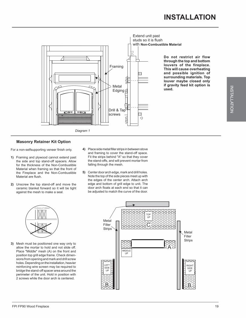
Masonry retainer Kit option
For a non-selfsupporting veneer finish only.
1) Framing and plywood cannot extend past the side and top stand-off spacers. Allow for the thickness of the Non-Combustible Material when framing so that the front of the Fireplace and the Non-Combustible Material are flush.
2) Unscrew the top stand-off and move the
ceramic blanket forward so it will be tight against the mesh to make a seal.
Diagram 1
3) Mesh must be positioned one way only to allow the mortar to hold and not slide off. Place "Middle" mesh (A) on the front and position top grill edge frame. Check dimen-sions from opening and mark and drill screw holes. Depending on the installation, heavier reinforcing wire screen may be required to bridge the stand-off spacer area around the perimeter of the unit. Hold in position with 2 screws while the door arch is centered.
do not restrict air flow through the top and bottom louvers of the fireplace. this will cause overheating and possible ignition of surrounding materials. top louver maybe closed only if gravity feed kit option is used.
4) Place side metal filler strips in between stove and framing to cover the stand-off space. Fit the strips behind "A" so that they cover the stand-offs, and will prevent mortar from falling through the mesh.
5) Center door arch edge, mark and drill holes. Note the top of the side pieces meet up with the edges of the center arch. Attach arch edge and bottom of grill edge to unit. The door arch floats at each end so that it can be adjusted to match the curve of the door.
installation
FPI FP90 Wood Fireplace20
INS
TALL
ATIO
N
Non-CombustibleMaterial
MetalFiller
Strips
Stand-off Spacers
Metal Filler Strip
60" (1524mm)
C
A
B B
3/4" (19mm)
2-1/2" (64mm)
1-1/4"(32mm)
48" (1219mm)29" (637mm)
2-1/2" (64mm)
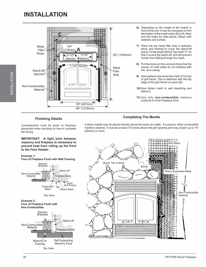
6) Depending on the height of the hearth in front of the unit, it may be necessary to trim the bottom of the mesh sides (B) to fit. Mark and drill holes for side pieces. Attach with washers and screws.
7) Place the top metal filler strip in between stove and framing to cover the stand-off space. Fit the strips behind Top mesh "C" so that it covers the stand-off, and will prevent mortar from falling through the mesh.
8) Put the doors on the unit and check that the veneer on both sides do not interfere with the door swing.
9) Use washers and screw top mesh (C) to top of grill frame. This is attached with the top edge of the grill frame on piece (B).
10) Now fasten mesh to wall sheathing and blend in.
11) Use only non-combustible masonry products to finish fireplace front.
finishing details
Consideration must be given to fireplace placement when deciding on how to complete the facing.
iMportant: a tight joint between masonry and fireplace is necessary to prevent heat from rolling up the front to the face Header.
Top View
example 1: face of fireplace flush with Wall framing.
example 2: face of fireplace flush withnon-combustible.
Top View
Wire Mesh
Mortar
Stone, Tile or Brick
Heavy Expanded Metal
Non-CombustibleMaterial
completing the Mantle
A stone mantle may be placed directly above the warm air outlet. If a wood or other combustible mantle is desired, it must be at least 18 inches above the grill opening and may project up to 10" (254mm) in front.
installation
FPI FP90 Wood Fireplace 21
INS
TALLAT
ION
Side Panel
TopPanel
Insulation
TopBrick
BottomVermiculite
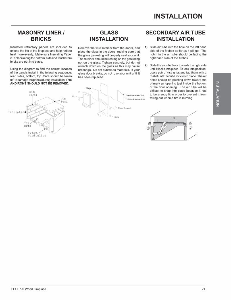
MasonrY liner / BricKs
Insulated refractory panels are included to extend the life of the fireplace and help radiate heat more evenly. Make sure Insulating Paper is in place along the bottom, side and rear before bricks are put into place.
Using the diagram to find the correct location of the panels install in the following sequence: rear, sides, bottom, top. Care should be taken not to damage the panels during installation. tHe andirons sHould not Be reMoVed.
secondarY air tuBe installation
1) Slide air tube into the hole on the left hand side of the firebox as far as it will go. The notch in the air tube should be facing the right hand side of the firebox.
2) Slide the air tube back towards the right side until it locks into place. To lock into position, use a pair of vise grips and tap them with a mallet until the tube locks into place. The air holes should be pointing down toward the primary air opening just inside the bottom of the door opening. The air tube will be difficult to snap into place because it has to be a snug fit in order to prevent it from falling out when a fire is burning.
Glassinstallation
Remove the wire retainer from the doors, and place the glass in the doors, making sure that the glass gasketing will properly seal your unit. The retainer should be resting on the gasketing not on the glass. Tighten securely, but do not wrench down on the glass as this may cause breakage. Do not substitute materials. If your glass door breaks, do not use your unit until it has been replaced.
installation
FPI FP90 Wood Fireplace22
INS
TALL
ATIO
N
asH draWer Kit option
During constant use, ashes should be removed every few days. The Ash Drawer Kit option provides a convenient and easy way to keep your wood stove clean. This ash drawer kit can only be used with the fireplace unit.
safety precautions
1) Do not allow ashes to build up to the loading doors! Only remove ashes when the fire has died down. Even then, expect to find a few hot embers.
2) Please take care to prevent the build-up of ash around the start-up air housing located inside the stove box, under the loading door lip.
3) If the ashes are disposed of by burial in soil or otherwise locally dispersed, they should be retained in the closed container until all cinders have thoroughly cooled. Other waste should not be placed in the ash container.
4) Never start a fire if the ash plug and ash drawer are not in place. This will cause over firing which can cause excessive warping of the stove. Over firing will void the warranty on your stove, and damage your fireplace.
5) The firebricks are brittle and can be damaged if the plug is replaced carelessly or pieces that are too large are forced through the hole.
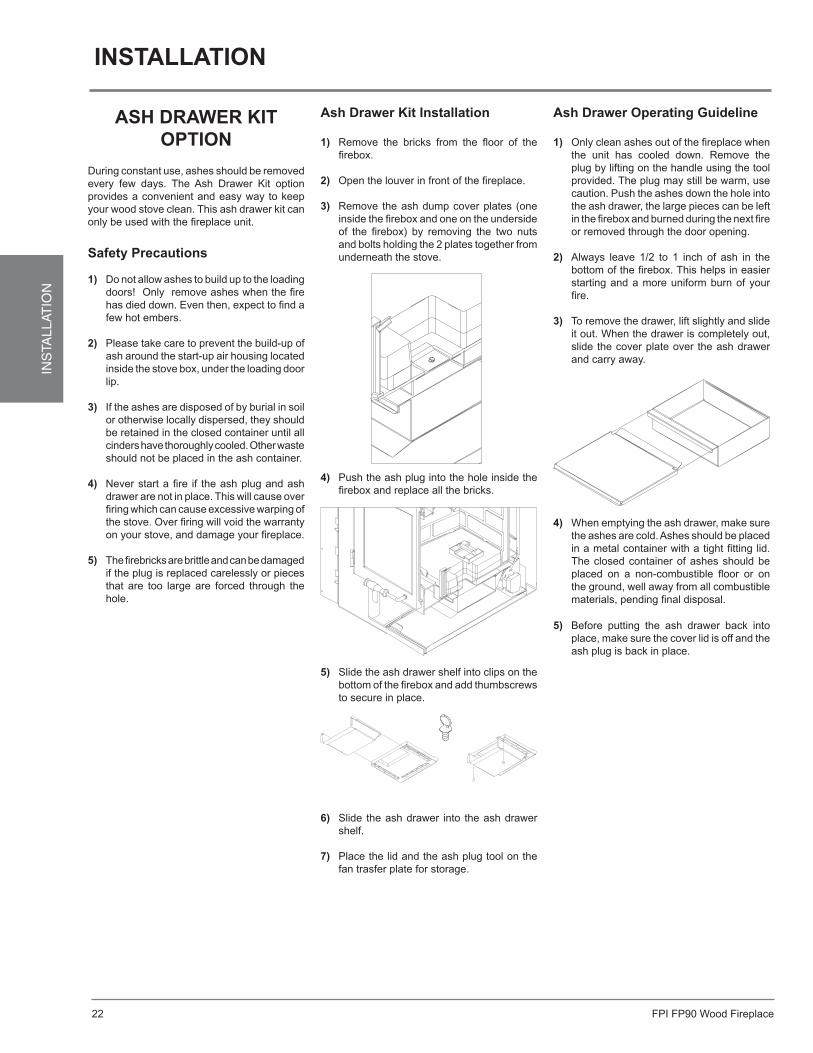
ash drawer Kit installation
1) Remove the bricks from the floor of the firebox.
2) Open the louver in front of the fireplace.
3) Remove the ash dump cover plates (one inside the firebox and one on the underside of the firebox) by removing the two nuts and bolts holding the 2 plates together from underneath the stove.
4) Push the ash plug into the hole inside the firebox and replace all the bricks.
5) Slide the ash drawer shelf into clips on the bottom of the firebox and add thumbscrews to secure in place.
6) Slide the ash drawer into the ash drawer shelf.
7) Place the lid and the ash plug tool on the fan trasfer plate for storage.
ash drawer operating Guideline
1) Only clean ashes out of the fireplace when the unit has cooled down. Remove the plug by lifting on the handle using the tool provided. The plug may still be warm, use caution. Push the ashes down the hole into the ash drawer, the large pieces can be left in the firebox and burned during the next fire or removed through the door opening.
2) Always leave 1/2 to 1 inch of ash in the bottom of the firebox. This helps in easier starting and a more uniform burn of your fire.
3) To remove the drawer, lift slightly and slide it out. When the drawer is completely out, slide the cover plate over the ash drawer and carry away.
4) When emptying the ash drawer, make sure the ashes are cold. Ashes should be placed in a metal container with a tight fitting lid. The closed container of ashes should be placed on a non-combustible floor or on the ground, well away from all combustible materials, pending final disposal.
5) Before putting the ash drawer back into place, make sure the cover lid is off and the ash plug is back in place.
installation
FPI FP90 Wood Fireplace 23
INS
TALLAT
ION
fan installation
01/13/11918-437
FP90
FAN INSTALLATION
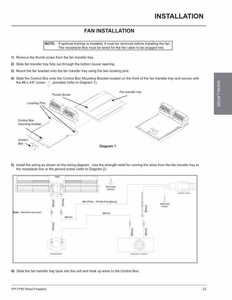
NOTE: If optional Ashtray is installed, it must be removed before installing the fan. The receptacle Box must be wired for the fan cable to be plugged into.
1) Remove the thumb screw from the fan transfer tray.
2) Slide fan transfer tray fully out through the bottom louver opening.
3) Mount the fan bracket onto the fan transfer tray using the two locating pins.
4) Slide the Control Box onto the Control Box Mounting Bracket located on the front of the fan transfer tray and secure with the #8 x 3/8” screw provided (refer to Diagram 1).
5) Install the wiring as shown on the wiring diagram. Use the strength relief for running the wires from the fan transfer tray to the receptacle box or the ground screw (refer to Diagram 2).
6) Slide the fan transfer tray back into the unit and hook up wires to the Control Box.
GROUNDGreen
GROUND[Green]
FAN
NEUTRAL -�FROM�FAN�[Black]
[Black] [Bla
ck]
[Bla
ck]
[Bla
ck]
[Black]
[Bla
ck]
[Whi
te]
[Whi
te]
Note: Red�wire�not�used.
Diagram 1
Fan transfer trayThumb Screw
Control Box mounting bracket
ControlBox
Locating Pins
installation
FPI FP90 Wood Fireplace24
INS
TALL
ATIO
N
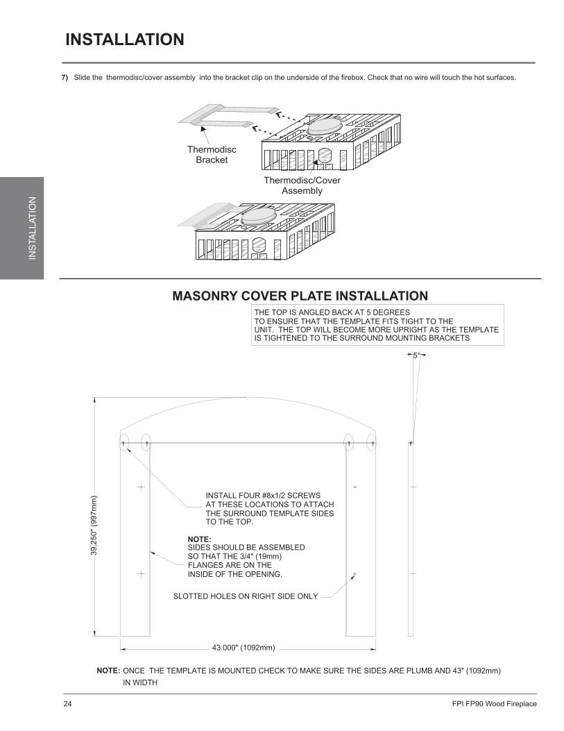
MasonrY coVer plate installation
5°
INSTALL FOUR #8x1/2 SCREWSAT THESE LOCATIONS TO ATTACHTHE SURROUND TEMPLATE SIDESTO THE TOP.
NOTE:SIDES SHOULD BE ASSEMBLED
FLANGES ARE ON THE
SLOTTED HOLES ON RIGHT SIDE ONLY
43.000" (1092mm)
39.2
50" (
997m
m)
ONCE THE TEMPLATE IS MOUNTED CHECK TO MAKE SURE THE SIDES ARE PLUMB AND 43" (1092mm) IN WIDTH
NOTE:
THE TOP IS ANGLED BACK AT 5 DEGREESTO ENSURE THAT THE TEMPLATE FITS TIGHT TO THE UNIT. THE TOP WILL BECOME MORE UPRIGHT AS THE TEMPLATEIS TIGHTENED TO THE SURROUND MOUNTING BRACKETS
SO THAT THE 3/4" (19mm)
INSIDE OF THE OPENING.
installation
01/13/11918-437
FP90
7) Slide the thermodisc/cover assembly into the bracket clip on the underside of the fi rebox. Check that no wire will touch the hot surfaces.

FPI FP90 Wood Fireplace 25
INS
TALLAT
ION
WITH THE SAME MOUNTING SCREWS AS THE SURROUND.INSTALL THE SURROUND TEMPLATE ONTO THE UNIT
WARNING: KEEP MASONRY MATERIAL AT LEAST 1/2" (13mm) FROM THIS TOP FACING GUIDE. THIS IS REQUIREDTO PREVENT MASONRY FACING MATERIAL FROM
HITTING THE TOP STIFFENER LOCATED ON THE BACK OF THE SURROUND WHICH IS HIGHER THAN THIS EDGE.
installation
FPI FP90 Wood Fireplace26
INS
TALL
ATIO
N
finisHinG triM Kit installation
10/10/06918-442a
WOOD FIREPLACEEX90 / R90
FINISHING TRIM KIT
PAGE 1 OF 2
2x4
FRA
MIN
G
LEFT
SID
E T
RIM
RIG
HT
SID
E T
RIM
2x4
FRA
MIN
G
TOP TRIM
STEP #1
NON-COMBUSTIBLE
AREA60"W x 51-5/8"H
(1524mm W x
1311mm H)2x4 HEADER (ON EDGE)
STEP #2
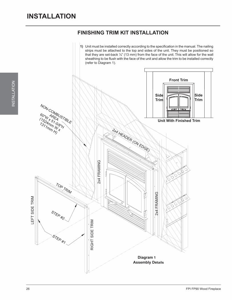
1) Unit must be installed correctly according to the specifi cation in the manual. The nailing strips must be attached to the top and sides of the unit. They must be positioned so that they are set-back ½” (13 mm) from the face of the unit. This will allow for the wall sheathing to be fl ush with the face of the unit and allow the trim to be installed correctly (refer to Diagram 1).
Diagram 1Assembly Details
Unit With Finished Trim
Side Trim
Side Trim
Front Trim
installation
FPI FP90 Wood Fireplace 27
INS
TALLAT
ION
10/10/06918-442a
WOOD FIREPLACEEX90 / R90
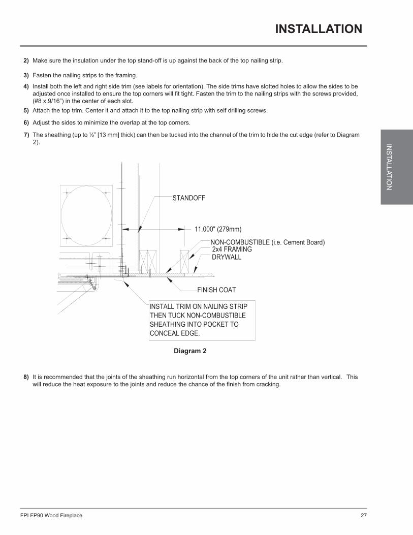
2) Make sure the insulation under the top stand-off is up against the back of the top nailing strip.
3) Fasten the nailing strips to the framing.
4) Install both the left and right side trim (see labels for orientation). The side trims have slotted holes to allow the sides to be adjusted once installed to ensure the top corners will fi t tight. Fasten the trim to the nailing strips with the screws provided, (#8 x 9/16”) in the center of each slot.
5) Attach the top trim. Center it and attach it to the top nailing strip with self drilling screws.
8) It is recommended that the joints of the sheathing run horizontal from the top corners of the unit rather than vertical. This will reduce the heat exposure to the joints and reduce the chance of the fi nish from cracking.
INSTALL TRIM ON NAILING STRIPTHEN TUCK NON-COMBUSTIBLESHEATHING INTO POCKET TO CONCEAL EDGE.
FINISH COAT
NON-COMBUSTIBLE (i.e. Cement Board)2x4 FRAMINGDRYWALL
STANDOFF
11.000" (279mm)
PAGE 2 OF 2
Diagram 2
6) Adjust the sides to minimize the overlap at the top corners.
7) The sheathing (up to ½” [13 mm] thick) can then be tucked into the channel of the trim to hide the cut edge (refer to Diagram 2).
installation
FPI FP90 Wood Fireplace28
INS
TALL
ATIO
N
fireplace screen installation
01/12/06918-444
FIREPLACE SCREEN INSTALLATIONEX90 / R90
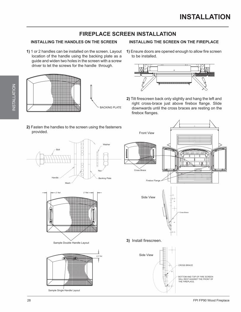
INSTALLING THE HANDLES ON THE SCREEN
1) 1 or 2 handles can be installed on the screen. Layout location of the handle using the backing plate as a guide and widen two holes in the screen with a screw driver to let the screws for the handle through.
2) Fasten the handles to the screen using the fasteners provided.
INSTALLING THE SCREEN ON THE FIREPLACE
1) Ensure doors are opened enough to allow fi re screen to be installed.
2) Tilt fi rescreen back only slightly and hang the left and right cross-brace just above fi rebox fl ange. Slide downwards until the cross braces are resting on the fi rebox fl anges.
3) Install fi rescreen.
Side View
Side View
Front View
installation

FPI FP90 Wood Fireplace 29
INS
TALLAT
ION
reGencY louVer installation
08/23/05918-433
R90 WOOD FIREPLACE
REGENCY LOUVERS
Installing the Top Louver
1) Add two (2) screws (¼-20 X ½”) to the front of the fi replace for mounting the top louver. The screws must be left loose to allow the top louver to slide onto them. Adjustment of theses screws will be needed to get the louver to sit fl ush with the front of the fi replace.
2) Place the top louver above the mounting screws located on the front of the fi replace and slide the louver down onto the screws.
Installing the Bottom Louver
3) Close the bottom louver and secure on the magnets provided (refer to Diagrams 1 and 2).
1) Fasten the bottom louver frame onto the front of the fi replace using two (2) screws (¼-20 X ½”).
2) Take the bottom louver and slide it onto the rotation pins located on the bottom louver frame.
NOTE: Take care not to scratch the paint on the front of the fi replace when installing the top louver.
Top Louver Mounting Tab (x2)
Bottom Louver Rotation Pin Tab (x2)
Bottom Louver Frame Rotation Pin Tab (x2)
Diagram 1 Bottom Louver Mounting Sequence
Diagram 2
installation
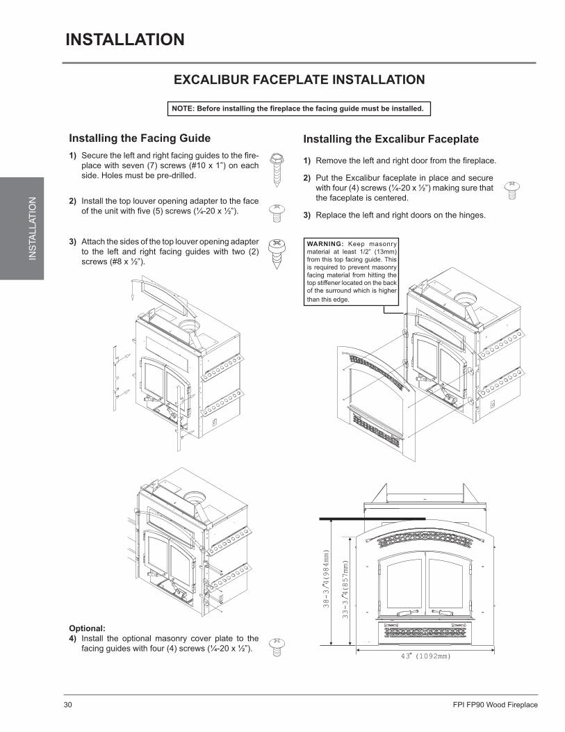
FPI FP90 Wood Fireplace30
INS
TALL
ATIO
N
11/12/09918-434
EX90 WOOD FIREPLACE
EXCALIBUR FACEPLATE
Installing the Facing Guide1) Secure the left and right facing guides to the fi re-
place with seven (7) screws (#10 x 1”) on each side. Holes must be pre-drilled.
2) Install the top louver opening adapter to the face of the unit with fi ve (5) screws (¼-20 x ½”).
Installing the Excalibur Faceplate
3) Replace the left and right doors on the hinges.
1) Remove the left and right door from the fi replace.
NOTE: Before installing the fi replace the facing guide must be installed.
3) Attach the sides of the top louver opening adapter to the left and right facing guides with two (2) screws (#8 x ½”).
Optional:4) Install the optional masonry cover plate to the
facing guides with four (4) screws (¼-20 x ½”).
2) Put the Excalibur faceplate in place and secure with four (4) screws (¼-20 x ½”) making sure that the faceplate is centered.
43” (1092mm)
33-3/4”(857mm)
38-3/4”(984mm)
WARNING: Keep masonry material at least 1/2” (13mm) from this top facing guide. This is required to prevent masonry facing material from hitting the top stiffener located on the back of the surround which is higher than this edge.
eXcaliBur faceplate installation
installation

FPI FP90 Wood Fireplace 31
INS
TALLAT
ION
eXcaliBur accent Kit installation
08/23/05918-438
WOOD FIREPLACE
EX90
ACCENT KIT INSTALLATION
3) Remove the 2 studs on the sides of the Hood. Insert the new studs through the holes and secure them by fi rst putting on the washer and then tighten the nut.
1) Remove the handles by removing the nut and screw. Install the new handles by placing them in position over the holes on the surround louver. Put the screws through the holes and secure them by tightening the nut.
4) Re-install faceplate with plated screws.
2) Place the emblem over the emblem design on the sur-round. Insert the studs through the holes. To secure them fi rst put on the split lock washer and then the nut and tighten.
installation
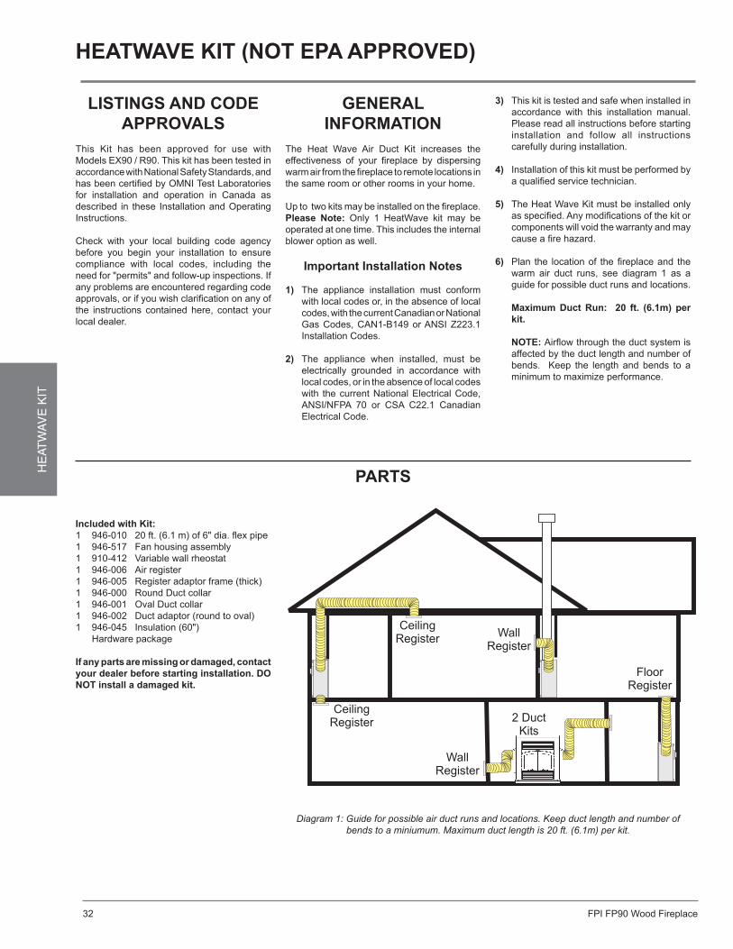
FPI FP90 Wood Fireplace32
HE
ATW
AV
E K
ITHeatWaVe Kit (not epa approVed)
Diagram 1: Guide for possible air duct runs and locations. Keep duct length and number of bends to a miniumum. Maximum duct length is 20 ft. (6.1m) per kit.
listinGs and code approVals
This Kit has been approved for use with Models EX90 / R90. This kit has been tested in accordance with National Safety Standards, and has been certified by OMNI Test Laboratories for installation and operation in Canada as described in these Installation and Operating Instructions.
Check with your local building code agency before you begin your installation to ensure compliance with local codes, including the need for "permits" and follow-up inspections. If any problems are encountered regarding code approvals, or if you wish clarification on any of the instructions contained here, contact your local dealer.
General inforMation
The Heat Wave Air Duct Kit increases the effectiveness of your fireplace by dispersing warm air from the fireplace to remote locations in the same room or other rooms in your home.
Up to two kits may be installed on the fireplace. please note: Only 1 HeatWave kit may be operated at one time. This includes the internal blower option as well.
important installation notes
1) The appliance installation must conform with local codes or, in the absence of local codes, with the current Canadian or National Gas Codes, CAN1-B149 or ANSI Z223.1 Installation Codes.
2) The appliance when installed, must be electrically grounded in accordance with local codes, or in the absence of local codes with the current National Electrical Code, ANSI/NFPA 70 or CSA C22.1 Canadian Electrical Code.
3) This kit is tested and safe when installed in accordance with this installation manual. Please read all instructions before starting installation and follow all instructions carefully during installation.
4) Installation of this kit must be performed by a qualified service technician.
5) The Heat Wave Kit must be installed only as specified. Any modifications of the kit or components will void the warranty and may cause a fire hazard.
6) Plan the location of the fireplace and the warm air duct runs, see diagram 1 as a guide for possible duct runs and locations.
Maximum duct run: 20 ft. (6.1m) per kit.
note: Airflow through the duct system is affected by the duct length and number of bends. Keep the length and bends to a minimum to maximize performance.
parts
included with Kit:1 946-010 20 ft. (6.1 m) of 6" dia. flex pipe1 946-517 Fan housing assembly1 910-412 Variable wall rheostat1 946-006 Air register1 946-005 Register adaptor frame (thick)1 946-000 Round Duct collar1 946-001 Oval Duct collar1 946-002 Duct adaptor (round to oval)1 946-045 Insulation (60") Hardware package
if any parts are missing or damaged, contact your dealer before starting installation. do not install a damaged kit.
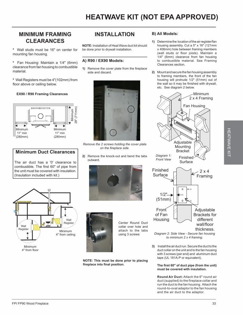
FPI FP90 Wood Fireplace 33
HE
ATW
AV
E K
ITHeatWaVe Kit (not epa approVed)
MiniMuM fraMinG clearances
* Wall studs must be 16" on center for mounting fan housing.
* Fan Housing: Maintain a 1/4" (6mm) clearance from fan housing to combustible material.
* Wall Registers must be 4"(102mm) from floor above or ceiling below.
Minimum duct clearances
The air duct has a '0' clearance to combustible. The first 60" of pipe from the unit must be covered with insulation. (Insulation included with kit.)
2) Remove the knock-out and bend the tabs outward.
installation
note: Installation of Heat Wave duct kit should be done prior to drywall installation.
a) r90 / eX90 Models:
1) Remove the cover plate from the fireplace side and discard.
Remove the 2 screws holding the cover plate on the fireplace side.
note: this must be done prior to placing fireplace into final position.
Center Round Duct collar over hole and attach to the tabs using 3 screws
B) all Models:
1) Determine the location of the air register/fan housing assembly. Cut a 5" x 16" (121mm x 406mm) hole between framing members (wall studs or floor joists). Maintain a 1/4" (6mm) clearance from fan housing to combustible material. See Framing Clearances section.
2) Mount and secure the fan housing assembly to framing members, the front of the fan housing will protrude 1/2" (51mm) out of the wall so it may be finished with drywall, etc. See diagram 2 below.
Diagram 2: Side View - Secure fan housing to minimum 2 x 4 framing.
Diagram 1: Front View
3) Install the air duct run. Secure the duct to the duct collar on the unit and to the fan housing with 3 screws (per end) and aluminum duct tape (UL 181A-P or equivalent).
the first 60" of duct pipe (from the unit) must be covered with insulation.
round air duct: Attach the 6" round air duct (supplied) to the fireplace collar and run the duct to the fan housing. Attach the round-to-oval adaptor to the fan housing and the air duct to the adaptor.
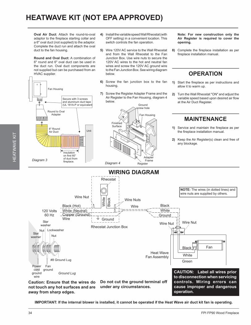
FPI FP90 Wood Fireplace34
HE
ATW
AV
E K
ITHeatWaVe Kit (not epa approVed)
Diagram 4
4) Install the variable speed Wall Rheostat (with OFF setting) in a convenient location. This switch controls the fan operation.
5) Wire 120V AC service to the Wall Rheostat and from the Wall Rheostat to the Fan Junction Box. Use wire nuts to secure the 120V AC wires to the hot and neutral fan wires and screw the 120V AC ground wire to the Fan Junction Box. See wiring diagram below.
6) Screw the fan junction box to the fan housing.
7) Screw the Register Adapter Frame and the Air Register to the Fan Housing, diagram 4 below.
oval air duct: Attach the round-to-oval adaptor to the fireplace starting collar and a 6" oval duct (not supplied) to the adaptor. Complete the duct run and attach the oval duct to the fan housing.
round and oval duct: A combination of 6" round and 6" oval duct can be used in the duct run. Oval duct components are not supplied but can be purchased from an HVAC supplier. operation
1) Start the fireplace as per instructions and allow it to warm up.
2) Turn the Wall Rheostat "ON" and adjust the variable speed based upon desired air flow at the Air Duct Register.
Maintenance1) Service and maintain the fireplace as per
the fireplace installation manual.
2) Keep the Air Register(s) clean and free of any blockage.
note: for new construction only the air register is required to cover the opening.
8) Complete the fireplace installation as per
fireplace installation manual.
Ground Lug caution: label all wires prior to disconnection when servicing controls. Wiring errors can cause improper and dangerous operation.
caution: ensure that the wires do not touch any hot surfaces and are away from sharp edges.
note: The wires (in dotted lines) and wire nuts are supplied by others.
iMportant: if the internal blower is installed, it cannot be operated if the Heat Wave air duct kit fan is operating.
WirinG diaGraM
do not cut the ground terminal off under any circumstances.
Diagram 3

FPI FP90 Wood Fireplace 35
OP
ER
ATIO
N
operatinG instructions
draft control
Both the primary and air wash drafts are controlled by the control rod located behind the bottom louver. To increase your draft, pull to the right for open, to decrease push to the left for closed.
WarninG: do not build the fire too close to the glass.
first fireWhen your installation is completed and inspected you are ready for your first fire.
1) Open draft control fully to the right to open.
2) Open firebox doors and build a small fire using paper and dry kindling. Secure doors on the firebox and wait a few minutes for a good updraft in the flue to establish the fire. Leaving the doors slightly open will help your fire start more rapidly and keep glass clean. Add more kindling to establish a hot coal bed before adding larger cordwood.
caution: fireplace equipped with doors should be operated only with doors fully open or doors fully closed. if doors are left partly open, gas and flame may be drawn out of the fireplace opening, creating risks of both fire and smoke.
3) With the draft still in the fully open position add two or three seasoned logs to your fire. Form a trench in the ash bed to allow air to reach the rear of the firebox prior to closing the doors.
4) during the first few days it may be more difficult to start the fire. as you dry out your firebrick, your draft will increase. Due to the large quantity of firebrick, which has a high water content, it may take many fires (20 or more) to thoroughly cure the firebrick. The firebrick will become lighter in colour as it dries out.
5) After about 15 to 20 minutes, when your wood has begun to burn strongly, adjust your draft control down to keep the fire at a moderate level.
operatinG instructions
WarninG: never build a roaring fire in a cold stove. always warm your stove up slowly!
6) Once a bed of coals has been established, you may adjust the draft control to a low setting to operate the unit at its most efficient mode.
7) For the first few days, the stove will give off an odour from the paint and oil burn off. This is to be expected as the high tempera-ture paint becomes seasoned. Windows and/or doors should be left open to provide adequate ventilation while this temporary condition exists. Burning the stove at a very high temperature the first few times may damage the paint. Burn fires at a moderate level the first few days.
8) For those units installed at higher elevations drafting problems may occur. Consult an experienced dealer on methods of increasing your draft. Follow the Flue Height Chart (Table 2, page 15).
9) Some cracking and popping noises may be experienced during the heating up process. These noises will be minimal when your unit reaches temperature.
10) Before opening your door to reload, open draft fully for approximately 10 to 15 seconds until fire has been re-established. This will minimize any smoking.
11) All fuel burning appliances consume oxygen during operation. It is important that you supply a source of fresh air to your unit while burning. Air drawn from the interior of the building will affect the performance of gas or oil furnaces, and exhaust fans and fan driven appliances. This may cause a negative pressure in the house allowing smoke to back into the home. The preferred source of combustion air is from outside the building. If possible, install the kit on the wind loading side of the building not the leeward or (negative pressure) side.
12) Green or wet wood is not recommended for your unit since most of the energy will be used to drive off the moisture instead of heating your home. As well, green or wet wood can result in dirty glass.
13) Always maintain clean glass. Clean glass means a clean flue; if you are experiencing dirty glass you may be operating a fire that is set too low. Ask your dealer for details.
14) Keep your spark arrester on the flue clean. It should be checked and maintained regularly, at least monthly.
safetY Guidelines1) Never use gasoline, gasoline type lantern
fuels, kerosene, charcoal lighter fuel or similar liquids to start or ‘freshen up’ a fire in your fireplace. Keep all such liquids well away from the unit while in use.
2) Keep the doors closed during operation. doors can be fully open during operation when optional fire screen door is used. Maintain all seals in good condition.
3) Do not burn large quantities of paper in your
fireplace. 4) If you have smoke detectors, prevent smoke
spillage as this may set off a false alarm.
5) Do not overfire fireplace. If overfiring takes place, stop adding fuel and close the draft control. Overfiring can cause extensive damage to your unit including warpage and premature steel corrosion. overfiring will void your warranty.
6) Do not permit creosote or soot build-up in the
chimney system. Check and clean chimney at regular intervals.
7) The fireplace face can be very hot. You
may be seriously burned if you touch the unit while in operation. Warn children of the burn hazard.
8) Do not connect this unit to a chimney flue
serving another appliance. 9) Do not use grates or andirons or other
methods for supporting fuel. Burn directly on the bricks.
10) When re-fuelling the fire turn off blowers, open draft prior to slowly opening the door. Failure to do so could result in smoke spillage.
11) Your unit should burn dry, standard firewood only. The use of “mill ends” is discouraged as this fuel can easily overheat your fireplace. Evidence of excessive overheating will void your warranty. As well, a large portion of sawmill waste is chemically treated lumber, which is illegal to burn in many areas. Salt drift wood, chemically treated fire logs and pressure treated woods, green or wet wood, must not be burned in your woodstoves.
12) Do not store any fuel closer than 3 feet from
your unit.
13) Clearances from front of the fireplace to combustible materials is 36" (i.e. from a sofa, table, etc.).
14) iMportant: Do not obstruct the convection louvers at any time. Blocking air into this area will cause excessively high firebox temperatures and a potentially dangerous situation.
15) Creosote: Formation and need for removal. When wood is burned slowly, it produces tar and other organic vapors, which combine with expelled moisture to form creosote. The creosote vapors condense in the relatively cool chimney flue of a slow-burning fire. As a result, creosote residue accumulates on the flue lining. When ignited, this creosote makes an extremely hot fire. The chimney shall be inspected at least twice a year during the heating season to determine when a creosote buildup has occurred. If creosote has accumulated it shall be removed to reduce the risk of a chimney fire.
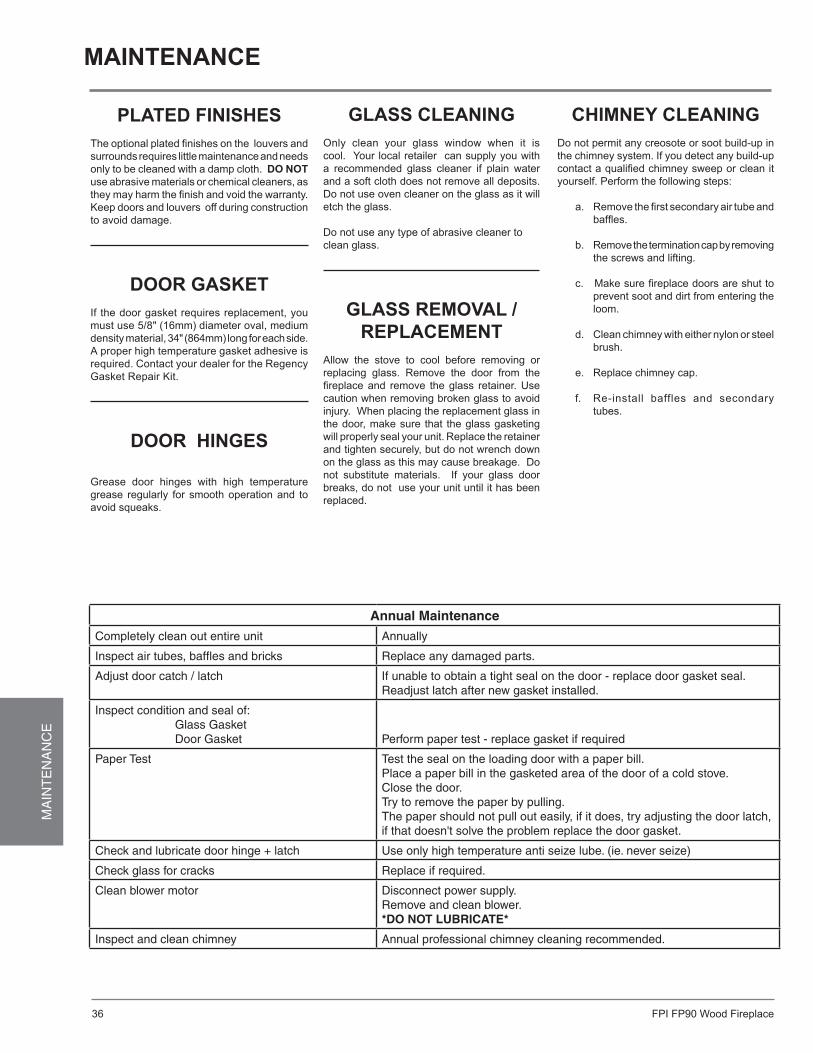
FPI FP90 Wood Fireplace36
MA
INT
EN
AN
CE
plated finisHesThe optional plated finishes on the louvers and surrounds requires little maintenance and needs only to be cleaned with a damp cloth. do not use abrasive materials or chemical cleaners, as they may harm the finish and void the warranty. Keep doors and louvers off during construction to avoid damage.
door GasKetIf the door gasket requires replacement, you must use 5/8" (16mm) diameter oval, medium density material, 34" (864mm) long for each side. A proper high temperature gasket adhesive is required. Contact your dealer for the Regency Gasket Repair Kit.
door HinGes
Grease door hinges with high temperature grease regularly for smooth operation and to avoid squeaks.
cHiMneY cleaninGDo not permit any creosote or soot build-up in the chimney system. If you detect any build-up contact a qualified chimney sweep or clean it yourself. Perform the following steps:
a. Remove the first secondary air tube and baffles.
b. Remove the termination cap by removing the screws and lifting.
c. Make sure fireplace doors are shut to
prevent soot and dirt from entering the loom.
d. Clean chimney with either nylon or steel brush.
e. Replace chimney cap.
f. Re-install baffles and secondary tubes.
Maintenance
Glass cleaninGOnly clean your glass window when it is cool. Your local retailer can supply you with a recommended glass cleaner if plain water and a soft cloth does not remove all deposits. Do not use oven cleaner on the glass as it will etch the glass.
Do not use any type of abrasive cleaner toclean glass.
Glass reMoVal /replaceMent
Allow the stove to cool before removing or replacing glass. Remove the door from the fireplace and remove the glass retainer. Use caution when removing broken glass to avoid injury. When placing the replacement glass in the door, make sure that the glass gasketing will properly seal your unit. Replace the retainer and tighten securely, but do not wrench down on the glass as this may cause breakage. Do not substitute materials. If your glass door breaks, do not use your unit until it has been replaced.
Annual Maintenance
Completely clean out entire unit Annually
Inspect air tubes, baffles and bricks Replace any damaged parts.
Adjust door catch / latch If unable to obtain a tight seal on the door - replace door gasket seal.Readjust latch after new gasket installed.
Inspect condition and seal of: Glass Gasket Door Gasket Perform paper test - replace gasket if required
Paper Test Test the seal on the loading door with a paper bill. Place a paper bill in the gasketed area of the door of a cold stove.Close the door. Try to remove the paper by pulling. The paper should not pull out easily, if it does, try adjusting the door latch, if that doesn't solve the problem replace the door gasket.
Check and lubricate door hinge + latch Use only high temperature anti seize lube. (ie. never seize)
Check glass for cracks Replace if required.
Clean blower motor Disconnect power supply.Remove and clean blower.*Do not LubricAte*
Inspect and clean chimney Annual professional chimney cleaning recommended.
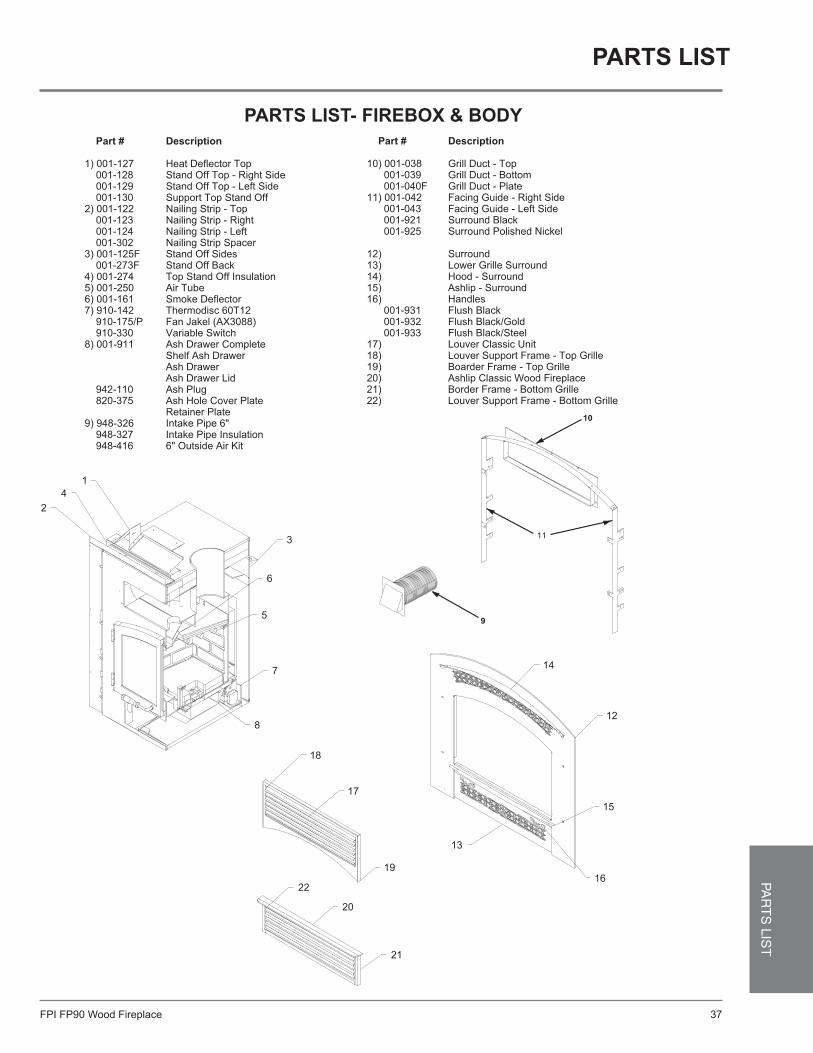
FPI FP90 Wood Fireplace 37
PAR
TS
LIST
parts list
parts list- fireBoX & BodY
16
12
13
15
14
42
1
8
7
6
5
3
Part # Description
1) 001-127 Heat Deflector Top 001-128 Stand Off Top - Right Side 001-129 Stand Off Top - Left Side 001-130 Support Top Stand Off2) 001-122 Nailing Strip - Top 001-123 Nailing Strip - Right 001-124 Nailing Strip - Left 001-302 Nailing Strip Spacer3) 001-125F Stand Off Sides 001-273F Stand Off Back4) 001-274 Top Stand Off Insulation5) 001-250 Air Tube6) 001-161 Smoke Deflector7) 910-142 Thermodisc 60T12 910-175/P Fan Jakel (AX3088) 910-330 Variable Switch8) 001-911 Ash Drawer Complete Shelf Ash Drawer Ash Drawer Ash Drawer Lid 942-110 Ash Plug 820-375 Ash Hole Cover Plate Retainer Plate9) 948-326 Intake Pipe 6" 948-327 Intake Pipe Insulation 948-416 6" Outside Air Kit
Part # Description
10) 001-038 Grill Duct - Top 001-039 Grill Duct - Bottom 001-040F Grill Duct - Plate11) 001-042 Facing Guide - Right Side 001-043 Facing Guide - Left Side 001-921 Surround Black 001-925 Surround Polished Nickel
12) Surround13) Lower Grille Surround14) Hood - Surround15) Ashlip - Surround16) Handles 001-931 Flush Black 001-932 Flush Black/Gold 001-933 Flush Black/Steel 17) Louver Classic Unit18) Louver Support Frame - Top Grille19) Boarder Frame - Top Grille20) Ashlip Classic Wood Fireplace21) Border Frame - Bottom Grille22) Louver Support Frame - Bottom Grille
19
20
22
21
18
17
9
10
11
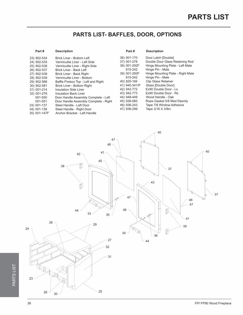
FPI FP90 Wood Fireplace38
PAR
TS
LIS
Tparts list
parts list- Baffles, door, options
Steel Handle - Left Door
Steel Handle - Right Door
Anchor Bracket - Left Handle
Door Latch [Double]
Double Door Glass Retaining Rod
Hinge Mounting Plate - Left Male
Hinge Pin - Male
Hinge Mounting Plate - Right Male
Hinge Pin - Male
Clip Glass Retainer
Glass [Double Door]
Ex90 Double Door - Ls
Ex90 Double Door - Rs
Wood Handle - Oak
Rope Gasket 5/8 Med Desnity
Tape 7/8 Window Adhesive
Tape 3/16 X 3/8in.
46
47
23
2830
26
24
44
31
25
35
27
32
29
34
33
46
47
36
44
39
41
43
42
Brick Liner - Bottom Left
Vermiculite Liner - Left Side
Vermiculite Liner - Right Side
Brick Liner - Back Left
Brick Liner - Back Right
Vermiculite Liner - Bottom
Baffle Firebox Top - Left and Right
Brick Liner - Bottom Right
Insulation Side Liner
Insulation Back Liner
902-534
902-535
902-536
902-537
902-538
902-539
902-566
902-581
001-214
001-276
23)
24)
25)
26)
27)
28)
29)
30)
31)
32)
38
Part # Description
33)
34)
35)
36)
37)
38)
39)
40)
41)
42)
43)
44)
45)
46)
47)001-137
001-138
001-147F
001-170
001-278
001-292F
815-242
001-293F
815-242
820-184
940-341/P
942-772
942-773
948-449
936-060
936-243
936-299
46
41
45
47
40
37
Part # Description
37
40
001-550 Door Handle Assembly Complete - Left
001-551 Door Handle Assembly Complete - Right
FPI FP90 Wood Fireplace 39
WarrantYWARRANTY
Revised: 01-04-07
Regency Fireplace Products are designed with reliability and simplicity in mind. In addition, our internal Quality Assurance Team carefully inspects each unit thoroughly before it leaves our door. FPI Fireplace Products International Ltd. is pleased to extend this limited lifetime warranty to the original purchaser of a Regency Product. This warranty is not transferable.
The Warranty: LifetimeCovered under the agreement are the following components:
Firebox, ceramic baffl e, vermiculite baffl e, steel baffl es (H2100), convector airmate, castings, ashdrawer, glass (thermal breakage), gold plating (against defective manufacture), airtubes (against warpage) and door handles.
The above will be covered for parts and subsidized labour for the fi rst fi ve years and parts only thereafter with the exception of the fi reboxes (see below).
FPI is not liable for freight or labor on any wood burning appliance replaced in fi eld.
Electrical components such as blowers, switches and thermodisc's are covered for two years parts and one year subsidized labour* from date of purchase.
Repair/replacement parts purchased by the consumer from FPI after the original coverage has expired on the unit will carry a 90 day warranty, valid with a receipt only. Any item shown to be defective will be repaired or replaced at our discretion. No labor coverage is included with these parts.
Conditions:Any part or parts of this unit which in our judgement show evidence of such defects will be repaired or replaced at FPI's option, through an accredited distribu-tor or agent provided that the defective part be returned to the distributor or agent Transportation Prepaid, if requested.
It is the general practice of FPI to charge for larger, higher priced replacement parts and issue credit once the replaced component has been returned to FPI and evaluated for manufacturer defect.
The authorized selling dealer is responsible for all in-fi eld service work carried out on your Regency product. FPI will not be liable for results or costs of workmanship from unauthorized service persons or dealers.
At all times FPI reserves the right to inspect product in the fi eld which is claimed to be defective.
All claims must be submitted to FPI by authorized selling dealers. It is essential that all submitted claims provide all of the necessary information including customer name, purchase date, serial #, type of unit, problem, and part or parts requested, without this information the warranty will be invalid.
Exclusions:This limited Lifetime Warranty does not extend to or include paint, door or glass gasketing, fi rebrick or trim. It does not cover installation and operational related problems such as over-fi ring, use of corrosive driftwood, downdrafts or spillage caused by environmental conditions, nearby trees, buildings, hilltops, mountains, inadequate venting or ventilation, excessive offsets, negative air pressures caused by mechanical systems such as furnaces, fans, clothes dryers etc.
At no time will FPI be liable for any consequential damages which exceed the purchase price of the unit. FPI has no obligation to enhance or modify any unit once manufactured. ie. as products evolve, fi eld modifi cations or upgrades will not be performed.
FPI will not be liable for travel costs for service work.
Installation and environmental problems are not the responsibility of the manufacturer and therefore are not covered under the terms of this warranty policy.
Any unit which shows signs of neglect or misuse is not covered under the terms of this warranty policy.
The warranty will not extend to any part which has been tampered with or altered in any way, or in our judgment has been subject to misuse.
Freight damage to stoves and replacement parts is not covered by warranty and is subject to a claim against the freight carrier by the dealer.
FPI will not be liable for acts of God, or acts of terrorism, which cause malfunction of the appliance.
Performance problems due to operator error will not be covered by this warranty policy.
Products made or provided by other manufacturers and used in conjunction with the operation of this appliance without prior authorization from FPI, may nullify your warranty on this product.
* Subsidy according to job scale as predetermined by FPI.
For Model: F1100 F3100 S3100 H2100 I1100 I3100 F2400 S2400 I2400 Z2510 FP90

printed in canadaRegency is a trademark of FPI Fireplace Products International Ltd.© Copyright 2011, FPI Fireplace Products International Ltd. All rights reserved.
Installer: Please complete the following information
dealer name & address: ______________________________________________
___________________________________________________________________
installer: ___________________________________________________________
phone #: ___________________________________________________________
date installed: ______________________________________________________
serial no.: __________________________________________________________
register your regency® warranty onlinewww.regency-fire.com
reasons to register your product online today!
• View and modify a list of all your registered products.• request automatic email notification of new product updates.• stay informed about the current promotions, events, and special
offers on related products.