fp1200 series - securatik bt. series analogue addressable fire panel: user instruction manual...
TRANSCRIPT

FP1200 SERIES
ANALOGUE ADDRESSABLE FIRE PANEL
USER INSTRUCTION MANUAL
Revision 4.2: August 1998
Downloaded from: http://www.guardianalarms.net


FP1200 SERIES ANALOGUE ADDRESSABLE FIRE PANEL: User Instruction Manual Revision 4.2: August 1998
TABLE OF CONTENTSTABLE OF CONTENTS
1. INTRODUCTION 1
2. PANEL OPERATION 2
2.1 LED INDICATIONS AND CONTROLS 3
2.2 GENERAL INDICATORS 4
2.3 CONTROLS 6
2.4 SOUNDERS 7
2.5 FIRE BRIGADE 8
2.6 ZONE INDICATORS (FP1216 ONLY) 9
2.7 LCD AND KEYPAD 9
3. NORMAL OPERATION 11
4. IN CASE OF FIRE 12
5. IN CASE OF PRE-WARNING 14
6. IN CASE OF FAULT 15
7. ROUTINE MAINTENANCE 16
7.1 DAILY 16
7.2 QUARTERLY 16
7.3 YEARLY 17


FP1200 SERIES ANALOGUE ADDRESSABLE FIRE PANEL: User Instruction Manual Revision 4.2: August 1998
1. INTRODUCTIONThe FP1200 User Instruction Manual is intended as a guide to users (operators) of the AritechFP1200 Series Analogue Addressable Fire Alarm Panel. Users are defined as those responsiblefor the routine day-to-day operation of the panel, including the handling of fire and fault conditionsidentified by the control panel.
The manual is written assuming no technical knowledge on the part of the user. The followingmanuals cover more detailed information on the FP1200 Series products:
Product Code
1. Aritech 950-900 Series Detector Installation Guide LKFP2103
2. Aritech 2000 Series Sensors Installation Guide LKFP2203
3. FP1200 Reference Guide MAN-087
(FP2000 Reference Guide with addendum sheet)
4. FP1200 Installation and Commissioning Manual MAN-083

FP1200 SERIES ANALOGUE ADDRESSABLE FIRE PANEL: User Instruction Manual Revision 4.2: August 1998
2. PANEL OPERATIONA view of the front of a typical FP1200 Series Fire panel is shown in Figure 1 below.
Figure 1: Fire Panel Front View
In order to describe the operation of a FP1200 series fire panel, the front panel has been dividedinto two sections, these being:
• LED indicators and controls
• LCD and keypad

FP1200 SERIES ANALOGUE ADDRESSABLE FIRE PANEL: User Instruction Manual Revision 4.2: August 1998
2.1 LED INDICATIONS AND CONTROLS
The LED indications and controls can further be broken down into:
• General indicators
• Controls
• Sounders
• Fire Brigade
• Enable/Disable keyswitch
• Zone indicators
Figure 2: General Indications and Controls
FP1200 SERIES ANALOGUE ADDRESSABLE FIRE PANEL: User Instruction Manual Revision 4.2: August 1998
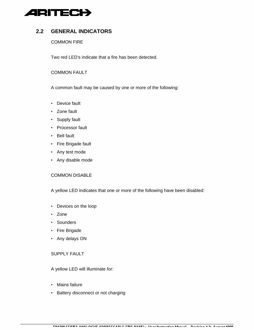
2.2 GENERAL INDICATORS
COMMON FIRE
Two red LED's indicate that a fire has been detected.
COMMON FAULT
A common fault may be caused by one or more of the following:
• Device fault
• Zone fault
• Supply fault
• Processor fault
• Bell fault
• Fire Brigade fault
• Any test mode
• Any disable mode
COMMON DISABLE
A yellow LED indicates that one or more of the following have been disabled:
• Devices on the loop
• Zone
• Sounders
• Fire Brigade
• Any delays ON
SUPPLY FAULT
A yellow LED will illuminate for:
• Mains failure
• Battery disconnect or not charging

FP1200 SERIES ANALOGUE ADDRESSABLE FIRE PANEL: User Instruction Manual Revision 4.2: August 1998
SYSTEM FAULT
A yellow LED indicates that a system fault has occurred. A system failure can be one ormore of:
• Internal memory failure
• Clock failure
• Watchdog time out
• Service link
• Logic error
• Memory lock
• No checksums calculated
• Hardware test fault
• Fireman’s' panel down
• Input fault
• Output fault
• Configuration fault
• Checksum fault
• Protected memory overwritten
• Time date wrong
• Access fault
• FEP fault
• Watchdog time-out
PROCESSOR RUNNING
A flashing green LED indicates normal operation.
SUPPLY ON
A green LED indicates that the system is receiving 24V power.
FP1200 SERIES ANALOGUE ADDRESSABLE FIRE PANEL: User Instruction Manual Revision 4.2: August 1998
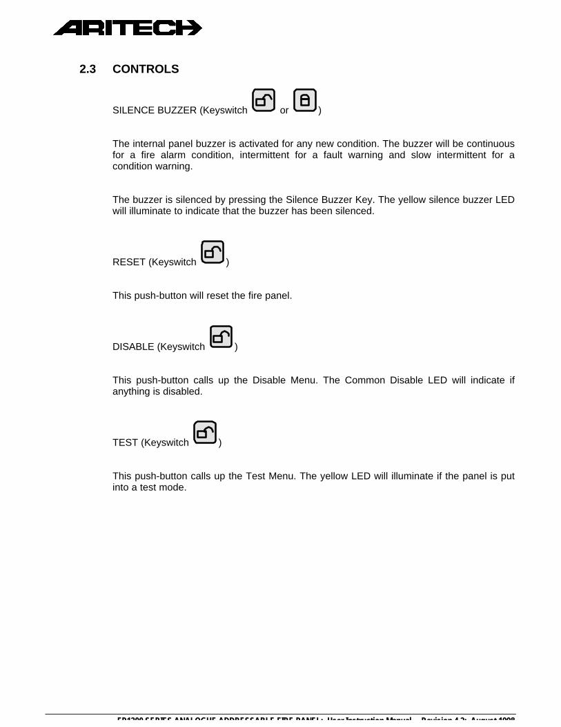
2.3 CONTROLS
SILENCE BUZZER (Keyswitch or )
The internal panel buzzer is activated for any new condition. The buzzer will be continuousfor a fire alarm condition, intermittent for a fault warning and slow intermittent for acondition warning.
The buzzer is silenced by pressing the Silence Buzzer Key. The yellow silence buzzer LEDwill illuminate to indicate that the buzzer has been silenced.
RESET (Keyswitch )
This push-button will reset the fire panel.
DISABLE (Keyswitch )
This push-button calls up the Disable Menu. The Common Disable LED will indicate ifanything is disabled.
TEST (Keyswitch )
This push-button calls up the Test Menu. The yellow LED will illuminate if the panel is putinto a test mode.

FP1200 SERIES ANALOGUE ADDRESSABLE FIRE PANEL: User Instruction Manual Revision 4.2: August 1998
2.4 SOUNDERS
SOUND
A red LED indicates that the sounders have been activated.
Depends on the operation mode of the panel. Please refer to your Installer to the exactway of operation.
DELAY ON/OFF
The programmed Sounder Delay may be toggled ON or OFF. Two LED’s indicate thestate.
FAULT/DISABLE (Keyswitch )
The Sounder Fault/Disable push-button allows the sounders to be disabled. Theassociated LED indicates that the sounders have been disabled or that a sounder fault ispresent.
The sounder fault can be:
• Sounder circuit open circuit
• Sounder circuit short circuit
• Sounder circuit fuse failure
SILENCE (Keyswitch )
A yellow LED indicates that the sounders have been silenced.
Please refer to your Installer to the exact way of operation.
FP1200 SERIES ANALOGUE ADDRESSABLE FIRE PANEL: User Instruction Manual Revision 4.2: August 1998
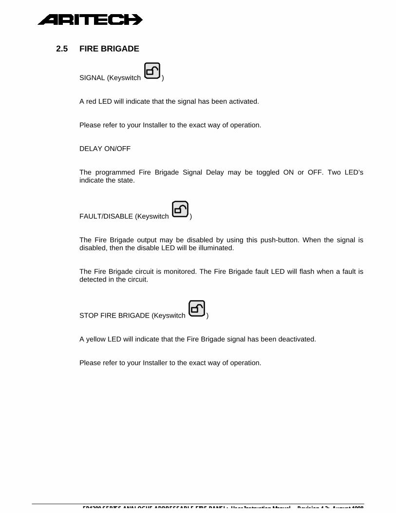
2.5 FIRE BRIGADE
SIGNAL (Keyswitch )
A red LED will indicate that the signal has been activated.
Please refer to your Installer to the exact way of operation.
DELAY ON/OFF
The programmed Fire Brigade Signal Delay may be toggled ON or OFF. Two LED’sindicate the state.
FAULT/DISABLE (Keyswitch )
The Fire Brigade output may be disabled by using this push-button. When the signal isdisabled, then the disable LED will be illuminated.
The Fire Brigade circuit is monitored. The Fire Brigade fault LED will flash when a fault isdetected in the circuit.
STOP FIRE BRIGADE (Keyswitch )
A yellow LED will indicate that the Fire Brigade signal has been deactivated.
Please refer to your Installer to the exact way of operation.

FP1200 SERIES ANALOGUE ADDRESSABLE FIRE PANEL: User Instruction Manual Revision 4.2: August 1998
KEYSWITCH: /
A keyswitch is provided to either allow or prevent operation of the fire panel controls. TheSilence Buzzer and Test keys will operate with the keyswitch in any position.
! Note: Level 1 for Disable and level 2 for Enable must not be confused with access levels1 and 2. There is no relation between the Enable/Disable keyswitch and theallocated access levels.
2.6 ZONE INDICATORS (FP1216 ONLY)
Each zone has two indicators. A red LED indicates a fire and a yellow LED indicates afault. The zone fault LED will flash for a fault condition. The zones are numbered from thetop left, from left to right.
Figure 3: Zone Fire and Fault Indication
2.7 LCD AND KEYPAD
Figure 4: LCD and Keypad

FP1200 SERIES ANALOGUE ADDRESSABLE FIRE PANEL: User Instruction Manual Revision 4.2: August 1998
KEYPAD
The keypad consists of 20 keys, 10 of which are alphanumeric keys.
The remaining 10 are assigned various functions as detailed below:
Alpha selection when using any of the 10 alphanumeric keys.
Used to display the latest alarm at any time.
Print screen function to print any screen to the internal or external printers.
Scroll key used to move between Alarm, Fault and Conditions, as well as to viewadditional information when the "MORE" prompt appears on the LCD.
Exit to previous menu
Enter or confirm
Move to the next field in the display
Move to the previous field in the display
Increment
Decrement

FP1200 SERIES ANALOGUE ADDRESSABLE FIRE PANEL: User Instruction Manual Revision 4.2: August 1998
3. NORMAL OPERATIONNormal operation is indicated by:
3.1 SUPPLY ON - Green Lamp ON
3.2 PROCESSOR RUNNING - Green Lamp FLASHING
3.3 SOUNDER INDICATORS - DELAY ON or DELAY OFF - Yellow Lamp ON
If a delay is ON, the disable LED will go on; this will be logged as a condition. Press theSILENCE BUZZER to silence the buzzer.
3.4 FIRE BRIGADE INDICATORS - DELAY ON or DELAY OFF - Yellow Lamp ON
If a delay is ON, the disable LED will go on; this will be logged as a condition. Press theSILENCE BUZZER to silence the buzzer.
3.5 All other Lamps OFF
3.6 The screen shows the System Status Menu as shown below:
3.7 The panel buzzer will sound for any abnormal condition that occurs with the fire panel.
FP1200 SERIES ANALOGUE ADDRESSABLE FIRE PANEL: User Instruction Manual Revision 4.2: August 1998
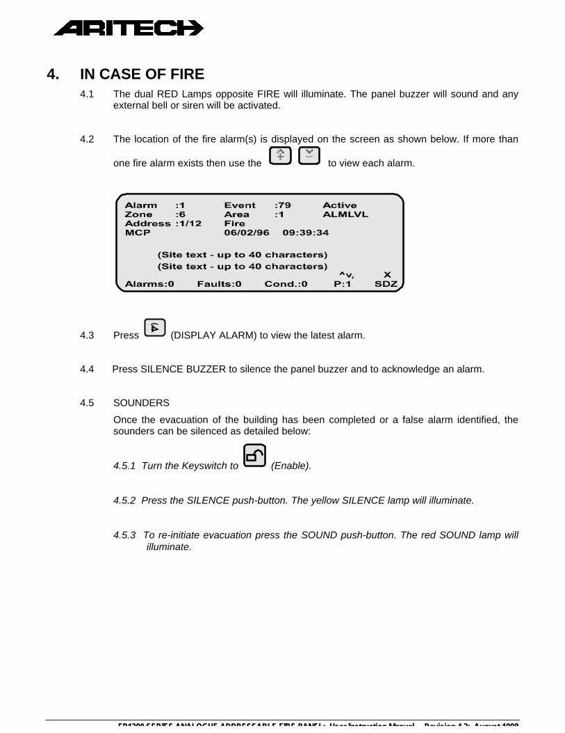
4. IN CASE OF FIRE4.1 The dual RED Lamps opposite FIRE will illuminate. The panel buzzer will sound and any
external bell or siren will be activated.
4.2 The location of the fire alarm(s) is displayed on the screen as shown below. If more than
one fire alarm exists then use the to view each alarm.
4.3 Press (DISPLAY ALARM) to view the latest alarm.
4.4 Press SILENCE BUZZER to silence the panel buzzer and to acknowledge an alarm.
4.5 SOUNDERS
Once the evacuation of the building has been completed or a false alarm identified, thesounders can be silenced as detailed below:
4.5.1 Turn the Keyswitch to (Enable).
4.5.2 Press the SILENCE push-button. The yellow SILENCE lamp will illuminate.
4.5.3 To re-initiate evacuation press the SOUND push-button. The red SOUND lamp willilluminate.
FP1200 SERIES ANALOGUE ADDRESSABLE FIRE PANEL: User Instruction Manual Revision 4.2: August 1998
4.6 RESTORE TO NORMAL
4.6.1 When the fire situation is under control, then the fire panel can be brought to a normal
condition by turning the keyswitch to and pressing the RESET push-button.
4.6.2 If a fire condition re-occurs, then one of the following exists:
• The fire is not under control - Refer to 4.2 above
• A Manual Call Point Glass is broken - Repair or isolate
• Detectors are contaminated with smoke - Clean detectors
4.6.3 Reset the fire panel as per 4.6.1.

FP1200 SERIES ANALOGUE ADDRESSABLE FIRE PANEL: User Instruction Manual Revision 4.2: August 1998
5. IN CASE OF PRE-WARNING5.1 The location of the detector in pre-warning is displayed on the LCD screen as shown
below. If more than one pre-warning condition exists, then use the to vieweach pre-warning condition.
5.2 Press SILENCE BUZZER to silence the panel buzzer and acknowledge the pre-warning.
5.3 Investigation should be carried out into the cause of the pre-warning condition.
5.4 RESTORE TO NORMAL
5.4.1 When the pre-warning condition is under control, then the fire panel can be brought to a
normal condition by turning the keyswitch to and pressing the RESET push-button.
5.4.2 If a pre-warning condition re-occurs, then one of the following exists:
• The condition is not under control - Refer to 5.3 above
• Detectors are contaminated with smoke - Clean detectors
5.4.3 Reset the fire panel as per 4.6.

FP1200 SERIES ANALOGUE ADDRESSABLE FIRE PANEL: User Instruction Manual Revision 4.2: August 1998
6. IN CASE OF FAULT6.1 The yellow lamp opposite FAULT indicates that a fault has occurred in the fire system.
6.2 Press the SILENCE BUZZER push button to silence the internal panel buzzer.
6.3 The nature of the fault is further displayed by a yellow lamp opposite:
6.3.1 A particular zone - Call maintenance engineer.
6.3.2 SUPPLY FAULT - Check mains supply and battery.
6.3.3 SYSTEM FAULT - Call maintenance engineer.
6.3.4 DISABLE - A zone, loop or device has been disabled.
6.3.5 TEST - A specific zone has been placed in test mode.
6.3.6 FAULT/DISABLE under SOUNDER - The warning bell or sirens have been disabledor a fault is present on the connection.
6.3.7 FAULT/DISABLE under FIRE BRIGADE - The FIRE BRIGADE warning has beendisabled or a fault is present on the connection.
6.4 The exact nature and location of the fault is displayed on the LCD screen as shown below:

FP1200 SERIES ANALOGUE ADDRESSABLE FIRE PANEL: User Instruction Manual Revision 4.2: August 1998
7. ROUTINE MAINTENANCEIn order to ensure the reliable operation of the FP2000 Series systems, they should be regularlytested and serviced.
The following maintenance routine should be adopted:
7.1 DAILY
On a daily basis the user should check the following:
7.1.1 that the panel indicates normal operation, or if not, that any fault indicated isrecorded in the logbook and reported to the maintenance personnel;
7.1.2 any fault warning recorded the previous day has received attention;
7.1.3 that the printer ribbon and paper supply are adequate (if applicable), or else replaceas shown in Appendix A.
7.2 QUARTERLY
On a quarterly basis the following actions should take place:
7.2.1 logbook entries should be checked and the necessary action taken;
7.2.2 the state of the batteries and corresponding connections should be checked;
7.2.3 the fire panel should be visually inspected for signs of moisture ingress and otherdeterioration;
7.2.4 the alarm, fault and ancillary functions of the fire panel should be tested.

FP1200 SERIES ANALOGUE ADDRESSABLE FIRE PANEL: User Instruction Manual Revision 4.2: August 1998
7.3 YEARLY
At least once every year the following should be checked:
7.3.1 the inspection and test routines recommended daily and quarterly should beperformed;
7.3.2 each detector should be checked for correct operation in accordance with themanufacturer's recommendations;
7.3.3 a visual inspection of all cable fittings and equipment should be undertaken to ensurethat no damage has taken place;
7.3.4 a visual inspection should be made to ensure that no structural or occupancychanges have affected the requirements for the siting of the manual call points,detectors and sounders.