fourth year report
TRANSCRIPT
1
Detecting Dark Energy with Atoms
By
James Eyres
Physics Research Project (F34PJM UK) (FYR 14-15)
MSCI Physics
Student Number: 4164849
Tutor: Dr J O’Shea
May, 2015
2
Abstract In order to explain the accelerating expansion of the universe it seems that dark energy must be modelled as a new scalar field, quintessence, whose range is coupled to the surrounding matter energy density. This new field should mediate a fifth force which has not yet been detected. The chameleon mechanism of quintessence would explain the accelerating expansion of the universe and also explain why the field has not been detected since the range of the scalar field changes with its environment- making it small on earth but large in the cosmos. This project will ultimately use the principles of atom interferometry in order to theoretically determine the constraints needed to be able to detect the fifth force, while modelling this fifth force around a massive spherical object and a point source along the way. Introduction & Literature Review The universe is expanding. This expansion is a logical consequence of the big bang. However, what may be less apparent is that the universe is expanding at an increasing rate i.e. accelerating. This is equivalent to stating that the cosmic scale factor 𝑎(𝑡) has a second derivative which is above zero [1]. The accelerating expansion was first discovered in 1998 by the Supernova Cosmology Project by observing distant supernovae [2]. The existence of dark energy, which has negative pressure and is spread equally throughout the cosmos, is the most widely accepted explanation for this accelerating expansion. This is not, however, the only proposed explanation for the accelerating expansion of the universe, another model is quintessence. This type of dark energy would have a non-constant state equation and a density that decreased with time. Further explanations include dark fluid, which attempts to combine dark energy and dark matter [3] and repulsive gravitational interactions of antimatter [4]. Dark energy is an obscure type of energy permeating all of space and is the driving force behind the accelerating expansion of the universe [5]. It is estimated that the observable universe is made up of 26.8% dark matter, 68.3% dark energy and 4.9% ordinary matter [6], according to the Planck mission team. The density of dark energy is lower than that of ordinary matter and dark matter, with a value of 6.91𝑥10−27𝐾𝑔 𝑚−3. There are two main proposed forms of dark energy. The most widely accepted form (as briefly mentioned above) is the cosmological constant, a homogeneous, constant energy density [7]. The other form includes scalar fields, for example moduli or quintessence, changing fields whose energy density varies in space and time. It is this second type of dark energy upon which this project will be based, and the reasons for this will be briefly summarised below. The cosmological constant can be formulated to be the value of the energy density of the vacuum of space. Einstein originally introduced the concept in 1917 [8] as an amendment to the theory of general relativity in order to achieve a stationary universe by supressing gravity. In 1929 Hubble discovered that all galaxies outside our local group are moving away from each other suggesting that the universe is expanding. Hence Einstein abandoned the cosmological constant and dubbed it his ‘greatest blunder’. Hereafter the cosmological constant was set at zero for around 80 years. As briefly mentioned the accelerating expansion of the universe was discovered in 1998 from numerous independent experimental observations. Furthermore the existence of dark energy was suggested and estimated to make up about 70% of the universe. Dark energy isn’t very well understood on a fundamental level, however it is apparent that the properties of dark energy should include that it clusters less (or perhaps not at all) than matter and that it dilutes slower than matter

3
as the universe expands. Due to the nature of a cosmological constant it is the simplest proposed form of dark energy, it is constant in time and space, which leads to the current, as of 2015, standard model of cosmology, the Lambda-CDM model. There is, however, a large problem with the cosmological constant, which has been called ‘the worst theoretical prediction in the history of physics’ [9]. This problem is that the value of the quantum vacuum, as predicted by quantum field theories, is extremely high. Furthermore, the quantum vacuum can be argued to be equivalent to the cosmological constant [10]. There is a discrepancy between the predicted quantum vacuum (and hence predicted cosmological constant) and the experimentally measured cosmological constant of 120 orders of magnitude, where the experimental cosmological constant is the smaller of the two. To put this discrepancy into perspective the statement, ‘the universe consists of exactly one elementary particle’ is more correct than the previous discrepancy, by at least 10 orders of magnitude. Some supersymmetry theories even predict a cosmological constant of zero. There is no known way to theoretically derive the observed cosmological constant from particle physics, this is the cosmological constant problem. This problem leads into the reason for the need of other models of dark energy, such as quintessence. Since the cosmological constant appears to be the wrong model for dark energy, introducing new models is the next logical step in trying to examine the fundamental properties of dark energy. Quintessence is a proposed form of dark energy, used to explain the accelerating expansion of the universe. Unlike the cosmological constant, quintessence is dynamic and changes over time, it can be attractive of repulsive depending on the ratio of its potential and kinetic energies. It is suggested that quintessence became repulsive when the universe was approximately 4 billion years old [11], and is suggested to be a fifth fundamental force, hence its name. A direct follow-on from quintessence is the chameleon, a scalar particle which couples to matter [12], that is a proposed dark energy candidate. The chameleon was first proposed in 2003 by Khoury et al.
[18] with multiple articles building upon the mathematical model, for example a 2014 paper by Burrage et al. [19] both showing that the chameleon force obeys a Yukawa potential. The chameleon has a variable effective mass that increases as a function of the surrounding energy density; due to this property the range of the mediated force is predicted to be small where the mass density is large and large when the mass density is small. As an example, on earth the range of the force is predicted to be less than 1mm whereas in intergalactic regions it is predicted to have a range of thousands of parsecs. This property explains the observed accelerating expansion of the universe, however, it also makes the chameleon very difficult to experimentally detect. Current constraints on the earth-bound tests of gravity and general relativity are too large to detect this hypothetical fifth force, as will be examined below.
4
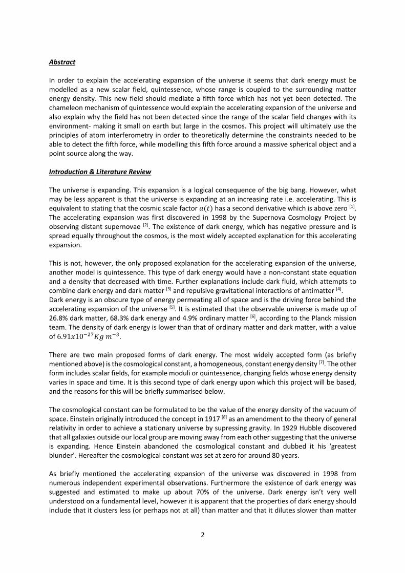
Throughout this project linear differential equations will be solved. As an illustration of the solution to these types of equations Newton’s law of universal gravitation has been derived starting from the Laplace and Poisson equations.
There are many different tests that probe general relativity, as described by a 2008 review article by Adelberger et al. The equivalence principle states that a homogeneous gravitational field is locally equivalent to a uniformly accelerated reference frame [13]. This principle can be tested, as described in the article and as pictured in Figure 1. The most direct test of this principle is that the trajectory of a point object freely falling in a gravitational field depends only on the object’s initial condition and not on its composition. As shown in the figure, the torque of the wire describes the gravitational field and a torque that does not equal zero can only occur for two reasons. Either, the two masses are in

5
different gravitational fields or the equivalence principle has been violated. If the force vectors on the masses aren’t parallel then a torque acts on the pendulum. This causes it to twist until the restoring torque of the fibre counteracts the initial torque. The twist of the pendulum can be measured by reflecting a collimated light beam from a mirror mounted on the pendulum. In this experiment, any violation of the equivalence principle could be attributed to the chameleon. However, no such violations are detected, to quite a significant precision.
The article goes on further to describe how no violations have been found of any tests of gravity and examines such experiments as short-range tests of the gravitational inverse-square law and spin-pendulum experiments. Both of these exploit the torque of massive objects in a system of wires to test their constituent principles, however, neither of which found any kind of violation or fifth force. It follows that there should be a reason why earth-bound experiments do not constrain the chameleon, if it is present, and there is. A partial explanation comes from the range of the chameleon on earth (as mentioned above this is below 1mm due to the large mass energy density) which leads to the thin shell effect. As depicted in Figure 2. The chameleon is screened by the size of the massive object, that is, most of the effects of a fifth field are blocked from detection due to the them not being able to ‘escape’ the source. The outer layer of the object would allow some of the chameleon force to
‘escape’ and be detected, however, this is only a small proportion of the object because, in order to ‘escape’ the source, the chameleon would have to be at or near the surface. The contribution from this surface chameleon force would be negligible when compared to the gravitational force of the source. Furthermore, the experimental limitations of these massive experiments produce larger errors than that of the force any surface chameleon would contribute. As a brief divergence from cosmology and gravity, the introduction of interferometry is prudent. Interferometry is any technique where waves, often electromagnetic, are superimposed and interfere with themselves in order to find out information about the waves [14]. It has a wide range of applications and is often used to measure small displacements to a good degree of accuracy. The most
Figure 1- ‘the left graph shows the inertial
and gravitational forces on a test-body
mounted at a latitude Ψ = 4 7 ∘ . The ratio of
the forces is exaggerated by a factor 200.
The right figure shows the forces on a
simplified torsion pendulum where 𝑚2 is
greater than 𝑚1. The pendulum tips by an
angle ϵ so that the centre of mass lies
vertically below P . ’ [13]
Figure 2- Illustration
of the thin shell effect
and explanation of
why this makes it
impossible to detect
chameleon forces
classically.

6
famous interferometry experiment was perhaps the Michelson-Morley experiment where the duo attempted to detect the relative motion of matter through the aether [15]. A beam of light from a monochromatic source is split into two and then recombined, this recombination produces an interference pattern of bright and dark rings that change proportionally to the difference in length of the two paths the light took. This experiment is sensitive to sub-wavelength changes in distance. Taking the idea of interferometry and expanding it, one arrives at atom interferometry. An atom interferometer is similar to a classical interferometer, the difference comes from the wave source. An atom interferometer exploits the wave characteristics of atoms and can be used to make highly accurate comparisons of displacement. Atom interferometry can constrain fundamental constants like the gravitational constant and could be used to search for gravitational waves [16] or the fifth force, as will be explained below. As described in Figure 3 the chameleon is not screened by a point mass (an atom) and thus can be detected. This leads to the idea of using atom interferometry to constrain the chameleon. Atom interferometry would detect gravitational forces plus an extra, fifth, force if indeed there was a chameleon present.
A 2007 study from Dimopoulos et al. performed atom interferometry with the hope of detecting the fifth force. Below is a brief summarisation of their experiment through the use of one of their paper’s figures. Figure 4 [17] demonstrates the experiment succinctly. The wavy lines in the figure represent the lasers while the smooth lines represent the atom trajectories. The y-axis shows the height of the atom while the x-axis shows the progression of time. The solid lines represent atoms that are only being subject to the effects of gravity while the dashed lines are atoms who have received an increase in energy (have increased energy state) due to the interaction with the lasers. There are two lasers in each interaction simply so one can excite the atom while the other can stimulate the atom to emit light into the other. This setup allows control over the fine-structure splitting of the atoms.
Although Figure 4 looks complex, it becomes easier to understand by following the trajectories of the atom. There are three instances when the atom interacts with the lasers. Whenever this happens the velocity of the atom changes. At the first interaction there is a probability of 0.5 that the atom will receive a ‘kick’, thus there are two paths which an atom can take (shown by the dashed and solid lines, where the dashed line atoms are travelling upwards more rapidly than the solid line atoms). Due to
Figure 3- Illustration of the
chameleon ‘escaping’ the atom
and being able to be detected.
Figure 4- Illustration of atom
interferometry as performed in
the 2008 study detailed in this
report [17].

7
the quantum nature of the experiment the atom actually takes both paths. Gravity slows the atom, hence accounting for the curved (deceleration) lines and eventually they begin to descend. The second interaction (at time T) is chosen so that the atom in the dashed line trajectory is flipped and vice versa with the solid line thus bringing the atom back together for the third interaction where the lasers perform the same action as at time 0. Much like classical interferometry, an interference pattern is observed from the recombination of the atom which can be used to detect very small displacements. This experiment couldn’t constrain the chameleon, however, it is clear to see that any deviation from the expected gravitational trajectory of the atom could be accounted for by the fifth force. Furthermore, atom interferometry is a relatively young field and so it is reasonable to predict that this type of experiment could constrain the chameleon in the future. A significant deviation from predicted gravitational interferometry results would constitute a smoking gun for the chameleon model of dark energy. Methodology It may be possible to detect chameleon forces using ultra-cold earth-bound experiments, or in other
words atom interferometry experiments. Although the chameleon field can be described by
relativistic quantum field theory, a much more manageable equation describing its non-relativistic
steady-state can be written as [18],
∇2𝜙 = 𝑉,𝜙+ ∑𝛽𝑖
𝑀𝑃𝑙𝜌𝑖𝑒
𝛽𝑖𝜙
𝑀𝑃𝑙𝑖 . [1]
Where 𝜙 is the field, 𝑉,𝜙 is the first derivative of the potential of the field with respect to 𝜙, 𝛽𝑖 is a
coupling constant, 𝜌𝑖 is the local density and 𝑀𝑃𝑙 is the Planck mass.
First, the equation of motion will be solved. It should be noted that throughout this project it has been
assumed that objects and fluids are perfect and have homogeneous density and pressure. For
simplicity the equation of motion was solved for a non-moving, spherically symmetric source object
with non-relativistic matter that has been placed into a medium of smaller, non-zero, homogeneous
density. Assuming that the coupling term, 𝛽𝑖, is in fact a constant and that 𝛽𝑖𝜙 ≪ 𝑀𝑃𝑙 the equation of
motion can be written as,
1
𝑟2
𝑑
𝑑𝑟[𝑟2 𝑑𝜙(𝑟)
𝑑𝑟] =
𝑑𝑉(𝜙)
𝑑𝜙+
𝜙(𝑟)
𝑀≡
𝑑
𝑑𝜙𝑉𝑒𝑓𝑓(𝜙) . [2]
Where ∇2 has been re-written in spherical polar coordinates and 𝑀 =𝑀𝑃𝑙
𝛽 has been defined for
continuity with the literature. This is congruent with Figure 5 which shows that the effective potential
can be written as,
𝑉𝑒𝑓𝑓(𝜙) = 𝑉(𝜙) + 𝜌𝑒𝛽𝜙
𝑀𝑃𝑙 . [3]

8
From Figure 5 it is clear to see where equation [3] comes from, since the effective potential is the
combined contributions from the actual potential which is of the runaway form and the coupling to
matter density which is dependent on the local density. The way in which the local density affects the
effective potential is shown, quite succinctly, in Figure 6. The effective potentials take on very different
forms depending on whether the local density is large or small.
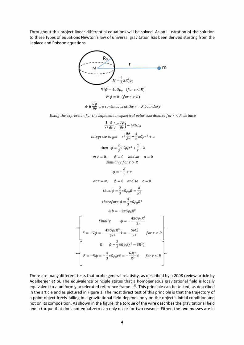
In order to appreciate the meaning of the term ‘density’ in this context Figure 7 has been included.
This shows the general system for which the equation of motion will be solved, where 𝜌𝑖𝑛 ≫ 𝜌𝑜𝑢𝑡 >
0 with the density of the source object, 𝜌𝑖𝑛, and the density of the medium 𝜌𝑜𝑢𝑡. The point at which
𝑟 = 0 describes the centre of the source object, while the point at which 𝑟 = 𝑅 describes the surface
of the source object, where the local density drops from the value of the density of the source object
to the value of the density of the local medium, thus creating this step function graph.
Figure 5- The effective potential 𝑉𝑒𝑓𝑓
(solid) is the sum of the two contributing
dashed/ dotted curves; the actual
potential 𝑉(𝜙) (dashed) and coupling to
matter density 𝜌 (dotted).
Figure 6- The effective potential in
regions of high local density (in an
atom for example) and low local
density (in the surrounding medium
for example). As 𝜌 decreases the
minimum shifts to larger values of 𝜙.
9
With anticipation of the results it is useful to classify two regimes that source objects can be a part of.
These are the thin shell regime and the thick shell regime. As described in the introduction, objects
that have a thin shell can be divided into infinitesimal volume elements of equal size and only those
elements which lie at the surface of the object will contribute to the exterior chameleon field. This is
not the case for objects in the thick shell regime and so the solution of the equation of motion is
dependent upon which regime is solved. Therefore the solutions to the equation of motion have been
split into two sections representing the two regimes. Not only will the equation of motion be solved
for two different regimes, it will be solved, much like any other second order differential, by splitting
each regime into adjacent areas which are connected through boundary conditions, specifically these
will be the interior of the source object, the thin shell of the source object (for the thin shell regime
only) and the exterior of the source object.
Thin shell regime
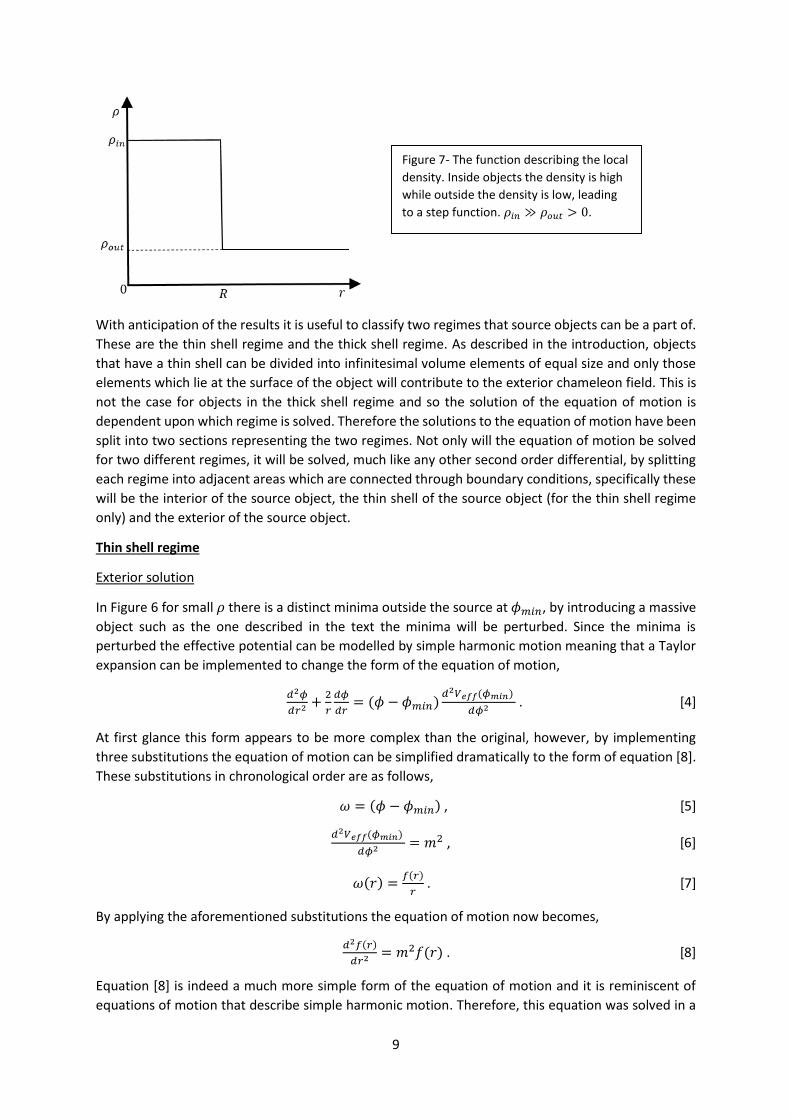
Exterior solution
In Figure 6 for small 𝜌 there is a distinct minima outside the source at 𝜙𝑚𝑖𝑛, by introducing a massive
object such as the one described in the text the minima will be perturbed. Since the minima is
perturbed the effective potential can be modelled by simple harmonic motion meaning that a Taylor
expansion can be implemented to change the form of the equation of motion,
𝑑2𝜙
𝑑𝑟2 +2
𝑟
𝑑𝜙
𝑑𝑟= (𝜙 − 𝜙𝑚𝑖𝑛)
𝑑2𝑉𝑒𝑓𝑓(𝜙𝑚𝑖𝑛)
𝑑𝜙2 . [4]
At first glance this form appears to be more complex than the original, however, by implementing
three substitutions the equation of motion can be simplified dramatically to the form of equation [8].
These substitutions in chronological order are as follows,
𝜔 = (𝜙 − 𝜙𝑚𝑖𝑛) , [5]
𝑑2𝑉𝑒𝑓𝑓(𝜙𝑚𝑖𝑛)
𝑑𝜙2 = 𝑚2 , [6]
𝜔(𝑟) =𝑓(𝑟)
𝑟 . [7]
By applying the aforementioned substitutions the equation of motion now becomes,
𝑑2𝑓(𝑟)
𝑑𝑟2 = 𝑚2𝑓(𝑟) . [8]
Equation [8] is indeed a much more simple form of the equation of motion and it is reminiscent of
equations of motion that describe simple harmonic motion. Therefore, this equation was solved in a
Figure 7- The function describing the local
density. Inside objects the density is high
while outside the density is low, leading
to a step function. 𝜌𝑖𝑛 ≫ 𝜌𝑜𝑢𝑡 > 0.

10
way that one would solve a simple harmonic motion equation of motion, by a trial solution of the
form,
𝑓(𝑟) = 𝐴𝑒𝑚𝑟 + 𝐵𝑒−𝑚𝑟 . [9]
By taking into consideration what happens at the extremes of the model, namely noting that as 𝑟 →
∞, 𝜙 → 𝜙𝑚𝑖𝑛 the solution can be written as,
𝜙 =𝐵
𝑟𝑒−𝑟𝑚 + 𝜙𝑚𝑖𝑛 , [10]
where 𝐵 is a constant that will be determined by applying boundary conditions to the other areas in
this regime.
Shell solution
By crossing the boundary of the object the position of the minima, 𝜙𝑚𝑖𝑛, is changed, as shown by
figure 8. This causes the field to ‘roll’ to the new value of the minima and hence this part of the model
is continuous. In this region the potential only ‘sees’ the coupling to matter potential contribution to
the effective potential, this means that the effective potential has a different value to that in the
exterior solution.
Since the effective potential follows the coupling to matter density it can be written that,
𝑉𝑒𝑓𝑓 = 𝜌𝑖𝑛𝑒𝛽𝜙
𝑀𝑃𝑙 . [11]
Furthermore, by using equation [2] and the simplifications from earlier, it can be written that,
∇2𝜙 ≃𝜌𝑖𝑛𝛽
𝑀𝑃𝑙 . [12]
In order to solve this equation the rule 𝜙 = 𝜙𝐶𝐹 + 𝜙𝑃𝐼 will be used, where 𝜙𝐶𝐹 is the complimentary
function and 𝜙𝑃𝐼 is the particular integral. This is a standard method for solving second order
differential equations of this form and it is done so by using the trial solutions,
𝜙𝐶𝐹 = 𝑎𝑟𝑛 , [13]
𝜙𝑃𝐼 = 𝑏𝑟𝑛 , [14]
where 𝑎 and 𝑏 are constants to be determined. Taking into consideration dimensional analysis
regarding the radius, namely that 𝑛 = 2 for the dimensions to be consistent it follows that the general
solutions are:
Figure 8- As the field moves from the
surrounding medium into the object there
is a sharp increase in local density, moving
the position of the minima so that the field
has to ‘roll’ to reach its new minima. Hence
why the effective potential is treated as
continuous.

11
𝜙𝐶𝐹 = 𝑎2 +𝑎1
𝑟 , [15]
𝜙𝑃𝐼 =𝜌𝑖𝑛𝛽
6𝑀𝑃𝑙𝑟2 . [16]
By combining equation [15] & [16] it is found that the general solution for the shell in the thin shell
regime is,
𝜙 = 𝑎2 +𝑎1
𝑟+
𝜌𝑖𝑛𝛽
6𝑀𝑃𝑙𝑟2 . [17]
As in the exterior solution, the constants 𝑎2 and 𝑎1 will be determined by applying the boundary
conditions at the appropriate regions.
Interior solution
For the interior solution, 𝜙 ≃ 𝜙𝑐, where 𝜙𝑐 is simply the field of the chameleon inside the source
object. By studying the high density area of Figure 6 which describes the interior of the source object
it is clear to see that the field ‘wants’ to ‘sit’ and the bottom of the curve, since it take a lot of energy
for the field to ‘move’ up the side of the steep curve. This minima is the point at which the field
minimises the potential, where the value of this field is 𝜙𝑐. In other words it is the value of the field
for which the first derivative of the effective potential is zero,𝑑
𝑑𝜙𝑉𝑒𝑓𝑓(𝜙𝑐) = 0.
Defining the constants
In order to define the constants 𝑎1 and 𝑎2 a common rule can be applied to the boundary of the
region, that is, at 𝑟 = 𝑅𝑟𝑜𝑙𝑙, where 𝑅𝑟𝑜𝑙𝑙 describes the point inside the object at which the thin shell
begins. At this radius the field must be smooth and continuous (𝜙 = 𝜙𝑐 & 𝑑𝜙
𝑑𝑟=
𝑑𝜙𝑐
𝑑𝑟= 0). Therefore,
by taking the solution to the shell region, equation [17], the solution to the interior region and applying
boundary conditions it is found that,
𝜙𝑐 = 𝑎2 +𝑎1
𝑅𝑟𝑜𝑙𝑙+
𝜌𝑖𝑛𝛽𝑅𝑟𝑜𝑙𝑙2
6𝑀𝑃𝑙 , [18]
−𝑎1
𝑅𝑟𝑜𝑙𝑙2 +
𝜌𝑖𝑛𝛽𝑅𝑟𝑜𝑙𝑙
3𝑀𝑃𝑙= 0 . [19]
Equation [19] can be rearranged to give a value for 𝑎1 which can then be substituted into [18] to give
a value for 𝑎2. Now that the constants have been found the general solution for the shell in the thin
shell regime can be quantified,
𝜙 =𝜌𝑖𝑛𝛽
3𝑀𝑃𝑙(
𝑟2
2+
𝑅𝑟𝑜𝑙𝑙3
𝑟) −
𝜌𝑖𝑛𝛽𝑅𝑟𝑜𝑙𝑙2
2𝑀𝑃𝑙+ 𝜙𝑐 For 𝑅𝑟𝑜𝑙𝑙 < 𝑟 < 𝑅 . [20]
The final constant to be determined in the thin shell regime is the value of 𝐵, this is found through a
similar method to the previous. The same boundary conditions are applied to the edge of the object
where 𝑟 = 𝑅, between the solutions for the shell and the exterior leading to the following equations,
𝑎2 +𝑎1
𝑅+
𝜌𝑖𝑛𝛽
6𝑀𝑃𝑙𝑅2 =
𝐵
𝑅𝑒−𝑅𝑚 + 𝜙𝑚𝑖𝑛 , [21]
−𝑎1
𝑅+
𝜌𝑖𝑛𝛽
3𝑀𝑃𝑙𝑅 = −
𝐵
𝑅2 𝑒−𝑅𝑚 −𝑚𝐵
𝑅𝑒−𝑅𝑚 . [22]

12
Values for 𝑎1 and 𝑎2 can be substituted into [22] and using simple algebra a value for 𝐵 can be found
and substituted into equation [10]. Furthermore, by using relations such as 𝑀 = 𝜌𝑉 =4
3𝜌𝑖𝑛𝜋𝑅3 and
defining 𝑅𝑟𝑜𝑙𝑙 = 𝑅 − Δ𝑅 where Δ𝑅 is the radius of the shell it is straight forward to find the solution
for the exterior of the thin shell regime,
𝜙 = −𝛽
4𝜋𝑀𝑃𝑙(
3Δ𝑅
𝑅)
𝑀𝑒−𝑚(𝑟−𝑅)
𝑟(
1
1+𝑅𝑚) + 𝜙∞ For 𝑅 < 𝑟 < ∞ . [23]
Where the substitution 𝜙𝑚𝑖𝑛 = 𝜙∞ has been made since the minimum value that the field can take is
the value of the field in the surrounding medium, which has been defined to be non-zero.
Thick shell regime
Exterior solution
The thick shell solution for the exterior is solved by following the same steps as the thin shell solution
for the exterior. However the constant for the general solution is calculated with the constraint
that 𝑅𝑟𝑜𝑙𝑙 → 0. Therefore this region is most easily solved by applying this limit to equation [22]. This
constraint effectively changes the value of the constant 𝐵 and hence the total solution, which is now
written as,
𝜙 = (−𝛽
4𝜋𝑀𝑃𝑙)
𝑀𝑒−𝑚(𝑟−𝑅)
𝑟(
1
1+𝑅𝑚) + 𝜙∞ For 𝑅 < 𝑟 < ∞ . [24]
Interior solution
The interior solution to the thick shell is solved in much the same way as the exterior, by applying the
constraint 𝑅𝑟𝑜𝑙𝑙 → 0, it is easiest to take equation [20], the solution for the shell in the thin shell
regime, replace 𝜙𝑐 with 𝜙𝑖 and apply the constraint. 𝜙𝑖 describes the initial value of the field so that
𝜙𝑖 = 𝜙(𝑟 = 0) and 𝜙𝑖 ≳ 𝜙𝑐. By applying these substitutions and constraints it follows that the
interior solution to the thick shell regime is,
𝜙 =𝜌𝑖𝑛𝛽𝑟2
6𝑀𝑃𝑙+ 𝜙𝑖 For 0 < 𝑟 < 𝑅 . [25]
Final solutions
Now that we have the solutions for each region of both systems we can write the solutions in a way
that eliminates the dependence on 𝜙(𝑟), in other words we can equate the equations at the boundary
of the source object, 𝑟 = 𝑅. In order to eliminate this dependence equations [24] & [25] are equated
thus eliminating 𝜙(𝑟). By applying conditions such as in natural units 𝑀𝑃𝑙2 =
1
8𝜋𝐺 and the Newtonian
potential Φ =𝐺𝑀
𝑅 the equation describing the thick shell solution becomes,
𝜙𝑖 = 𝜙∞ − 3𝛽Φ𝑀𝑃𝑙 . [26]
A similar method can be used to eliminate the 𝜙(𝑟) dependence in the thin shell regime. To do this
equations [20] & [23] are equated since the boundary is continuous, note that 𝑅𝑚 ≪ 1. From here
we can perform a number of operations that will simplify our equation such as, 𝜌 = 𝜌𝑖𝑛 =𝑀
𝑉=
3𝑀
4𝜋𝑅3,
applying a Taylor series since 𝑅𝑟𝑜𝑙𝑙 = 𝑅 − Δ𝑅 where Δ𝑅 ≪ 1, in natural units 𝑀𝑃𝑙2 =
1
8𝜋𝐺 and the
Newtonian potential Φ =𝐺𝑀
𝑅. By following this logic the equation describing the thin shell regime is,
Δ𝑅
𝑅=
𝜙∞−𝜙𝑐
6𝛽𝑀𝑃𝑙Φ . [27]

13
Thin shell regime
In order to investigate what types of object have a thin or thick shell equation [27] can be used, since,
for a thin shell Δ𝑅
𝑅≪ 1 and for a thick shell this is not true. Therefore equation [27] can be investigated
numerically to determine whether a chosen system has a thin or thick shell but first it must be turned
into a form with quantifiable terms. We can eliminate 𝜙𝑐 immediately by applying the condition
that 𝜙∞ ≫ 𝜙𝑐. In order to eliminate 𝜙∞ a value must be chosen for the potential of the chameleon
field. A common choice for this potential is [19],
𝑉(𝜙) =Λ5
𝜙 . [28]
From Figure 5 it is clear to see that the effective potential of our system is given by the summation of
the constituent parts making up the contributions to the effective potential, one of which is 𝑉(𝜙),
therefore we can substitute our value for the potential into the equation describing the effective
potential,
𝑉𝑒𝑓𝑓(𝜙) =Λ5
𝜙+ 𝜌𝑒
𝛽𝑖𝜙
𝑀𝑃𝑙 . [29]
Due to the fact that 𝜙∞ is the term that must be eliminated we must investigate the effective potential
in the exterior region of the problem. By investigating the exterior region 𝜌 can be rewritten as 𝜌∞,
likewise 𝜙 can be rewritten as 𝜙∞, where these terms describe the local density and field of the
surrounding medium respectively. Much like what was done with the equation of motion the
condition that the coupling is constant and 𝛽𝜙 ≪ 𝑀𝑃𝑙 is applied to the effective potential. By
differentiating this equation with respect to the field and by setting the result 𝑑(𝑉𝑒𝑓𝑓(𝜙))
𝑑𝜙= 0 a value
for the exterior field is obtained,
𝜙 = 𝜙∞ = (Λ5𝑀𝑃𝑙
𝜌∞𝛽)
1
2 . [30]
In order to arrive at the final solution 𝜙𝑐 is eliminated from equation [27], as above, and then equation
[30] is substituted into the remaining equation to eliminate 𝜙∞,
Δ𝑅
𝑅=
4
3(
𝑀𝑃𝑙3
𝜌∞)
1
2(
Λ5
𝛽3)
1
2 𝑅
𝑀 . [31]
This equation is useful since it describes the ratio of the radius of the thin shell of the source object to
the radius of the source object. If this ratio is much smaller than 1 then the object has a thin shell,
otherwise it has a thick shell. The next section will discuss the procedure of classifying objects as either
in the thin shell regime or the thick shell regime depending on the value of this ratio.
Classification of source objects
Equation [31] describes the solution to the thin shell regime and it does so in quantifiable terms. That
is to say that the mass and radius of the source object can be chosen as well as the background density
of the medium in which the source object has been placed. As discussed the ratio describing the thin
shell regime is Δ𝑅
𝑅≪ 1 and from this we can investigate the values for which the parameters 𝛽 and Λ
are valid. First, however, equation [31] will be rewritten using the condition 𝑀 =𝑀𝑃𝑙
𝛽 and defining the
radius 𝑅𝑐 and mass 𝑀𝑐 of the source as such,

14
Δ𝑅𝑐
𝑅𝑐=
4
3(
𝑀3Λ5
𝜌∞)
1
2 𝑅𝑐
𝑀𝑐 . [31]
The fraction describing the ratio of the radius of the thin shell to the radius of the object has been
chosen to be 1
100. This essentially means that for
1
100>
4
3(
𝑀3Λ5
𝜌∞)
1
2 𝑅𝑐
𝑀𝑐 the source object has a thin shell
while for 1
100<
4
3(
𝑀3Λ5
𝜌∞)
1
2 𝑅𝑐
𝑀𝑐 the source object has a thick shell. With this inequality one can chose a
range of values that 𝑀 or Λ could take, given by the following ranges. Λ is predicted to be of order
1 𝑚𝑒𝑉 given by the Planck 2013 results [6]. An upper bound for Λ is given by Casimir force
measurements Λ < 100 𝑚𝑒𝑉 [20] thus giving the range 10−2 𝑚𝑒𝑉 < Λ < 10+2 𝑚𝑒𝑉 as physically
acceptable values. Conversely 𝑀 is poorly constrained and has a much broader range. A lower bound
for the range is 104 𝐺𝑒𝑉 which has been determined from the measured 1𝑠 − 2𝑠 interval in
hydrogen[21] while the reduced Planck mass 𝑀𝑃𝑙 = 2 × 10¹⁸ 𝐺𝑒𝑉 has been used as the upper bound,
given by laboratory and astrophysical tests of gravity [22] as well as a lack of clarity over the physics
above the Planck scale. With these ranges a parameter space can be produced. This is a representation
of all of the possible values of Λ & 𝑀, that is to say the values of these parameters for which the
chameleon theory is physical and hence valid. Through the creation of a Matlab code, the details of
which are described in Appendix 1, it is possible to investigate whether a given object has a thin or
thick shell for each possible value of Λ & 𝑀 by investigating whether equation [31] is above or
below 1
100. Hence, classification of objects as either being in the thin shell regime or the thick shell
regime is possible. The following sections depict the results obtained by defining a number of different
systems and applying them to the Matlab code.
Rubidium atom in a vacuum chamber
Figure 9 shows the resulting parameter space from defining the source object as a rubidium atom and
defining the surrounding medium as a vacuum chamber with a background density of 10−10 𝑇𝑜𝑟𝑟 of
hydrogen. As the figure shows, most of the parameter space has been coloured black, this corresponds
to the areas of the parameter space for which equation [31] is above 1
100, thus making rubidium fall
into the thick shell regime. There is a region of the parameter space that is coloured white, this area
describes the values of Λ & 𝑀 that make rubidium fall into the thin shell regime, however, this region
Figure 9- A rubidium atom in a
vacuum chamber of 10−10 𝑇𝑜𝑟𝑟
of hydrogen is in the thick shell
(black) regime for most of the
parameter space.
15
is much smaller than the thick shell region and so it is a safe assumption that rubidium has a thick shell
and hence chameleon forces may be detectable through tests on atoms of this size.
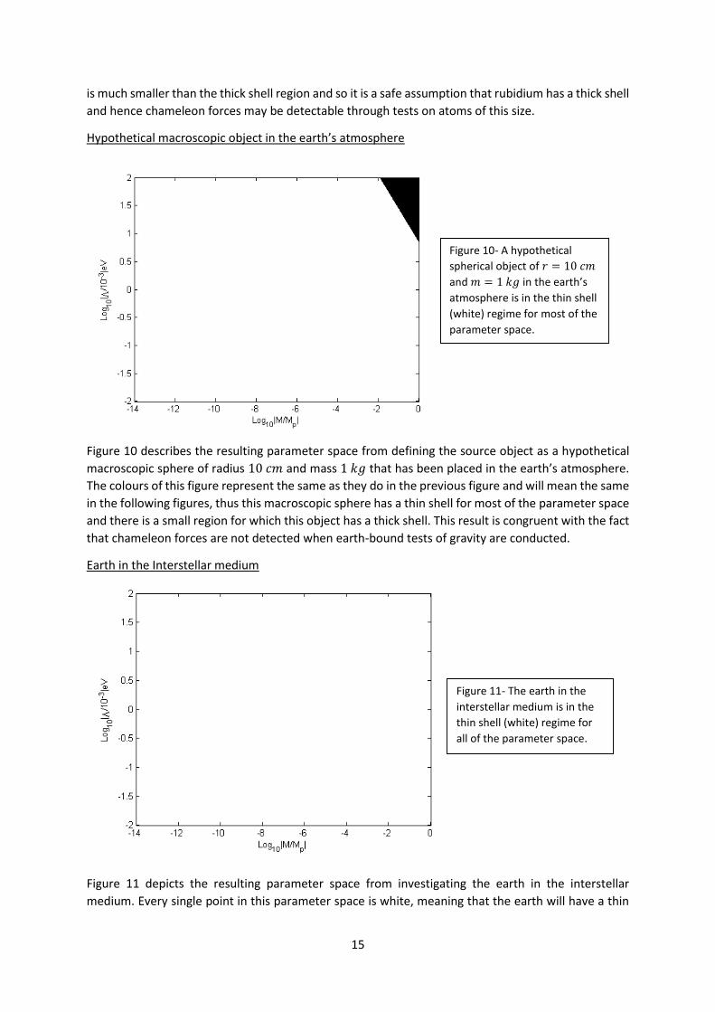
Hypothetical macroscopic object in the earth’s atmosphere
Figure 10 describes the resulting parameter space from defining the source object as a hypothetical
macroscopic sphere of radius 10 𝑐𝑚 and mass 1 𝑘𝑔 that has been placed in the earth’s atmosphere.
The colours of this figure represent the same as they do in the previous figure and will mean the same
in the following figures, thus this macroscopic sphere has a thin shell for most of the parameter space
and there is a small region for which this object has a thick shell. This result is congruent with the fact
that chameleon forces are not detected when earth-bound tests of gravity are conducted.
Earth in the Interstellar medium
Figure 11 depicts the resulting parameter space from investigating the earth in the interstellar
medium. Every single point in this parameter space is white, meaning that the earth will have a thin
Figure 10- A hypothetical
spherical object of 𝑟 = 10 𝑐𝑚
and 𝑚 = 1 𝑘𝑔 in the earth’s
atmosphere is in the thin shell
(white) regime for most of the
parameter space.
Figure 11- The earth in the
interstellar medium is in the
thin shell (white) regime for
all of the parameter space.

16
shell regardless of the values of Λ & 𝑀 in these ranges. This is to be expected since the current
theoretical model of our solar system matches the experienced motion of the planet. If chameleon
forces were detectable from the earth then consequentially the theoretical theories that describe
planetary motion would not match the observable motion of the planets.
Average sized galaxy in the average density of the universe
The final system to be investigated is that of an average sized galaxy in a background density equal to
the average density of the universe, shown in Figure 12. This gives a result similar to Figure 10 where
most of the parameter space puts this galaxy into the thin shell regime, there is however a small region
of the parameter space that allows galaxies to be in the thick shell regime.
Atom Interferometry
From Figure 9 it is clear to see that atoms have a thick shell and so there is a possibility that chameleon
forces could be detected through experiments involving atoms since the chameleon force is not
supressed by the atom. Atom interferometry is the ideal experiment to probe the forces incident on
an atom and so this is where the chameleon theory turns.
Atom interferometry experiments produce a probability density as an output which is dependent on
the phase difference of the atomic wavefunction [23],
𝑃 = cos2 (Δ𝜙
2) , [32]
where Δ𝜙 is the phase difference. Atom interferometry uses the superposition of atomic
wavefunctions in order to deduce properties of a system. It is similar to classical interferometry which
uses the superposition of light waves in order to deduce properties of a system.
Since atom interferometry experiments produce a probability distribution which is dependent upon
the phase difference we must find the theoretical prediction of the phase difference. To approach this
problem we begin with an equation which describes the phase difference as a combined contribution
from the phase difference of the path difference and phase difference of the light of the atom
interferometer [24],
Δ𝜙𝑡𝑜𝑡𝑎𝑙 = Δ𝜙𝑝𝑎𝑡ℎ + Δ𝜙𝑙𝑖𝑔ℎ𝑡 . [33]
Figure 12- An average sized galaxy
in a surrounding medium with a
density equal to the average
density of the universe is in the
thin shell (white) regime for most
of the parameter space.
17
Since equation [33] has two contributory factors they will be investigated separately so that this
equation can become quantifiable. The first term describes the phase difference given by the
difference in path length that atoms take in an atom interferometry experiment. The second term
describes the phase difference given by the interaction of atoms with the laser beams.
Path difference
The general set up of an atom interferometer is described by Figure 4 in the literature review. Here
there are two distinct paths that the atom takes, given by the probabilistic way that each atom
interacts with the laser beams. To make things simpler we will define a ‘path A’ and a ‘path B’ where
path A is above path B, defined that way for no particular reason. The phase difference due to the
path difference can be calculated by finding the difference between the actions of the two paths which
is given by,
Δ𝜙𝑝𝑎𝑡ℎ =1
ħ(𝑆𝑐𝑙
𝐵 − 𝑆𝑐𝑙𝐴) . [34]
𝑆𝑐𝑙𝐵 is the classical action for path B, 𝑆𝑐𝑙
𝐴 is the classical action for path A and ħ is the reduced Planck
constant. With this knowledge it becomes clear that the Lagrangian of each path must be known in
order to calculate the action which can be used to find the path difference. The classical action of each
path is calculate by integrating the Lagrangian 𝐿[𝑧(𝑡), ż(𝑡)] of each path between initial time 𝑡0 and
final time 𝑡𝑓 as such,
𝑆𝑐𝑙 = ∫ 𝐿[𝑧(𝑡), ż(𝑡)]𝑡𝑓
𝑡0𝑑𝑡 . [35]
In order to begin to solve this problem we must define the initial positions and velocities of each point
that the atom interacts with a laser beam and substitute them into equation [36] which describes the
Lagrangian. The reason that we must redefine initial positions and velocities at each interaction with
the laser beam is due to the fact that the atom can receive a kick from the laser beam thus changing
its Lagrangian. In essence, there will be four Lagrangians, two to describe path A and two to describe
path B, all of which are given by the general equation describing a Lagrangian,
𝐿 =1
2𝑚 ż(𝑡)2 − 𝑚𝑔𝑧 . [36]
SUVAT is used in order to define the initial positions and velocities of the atom at each interaction
with the laser beam. By assuming complete absorption of photons by the atom it either receives a kick
equal to ħ𝐾 if going from state 1 → 2 or a kick equal to ħ𝐾 in the opposite direction if going from
state 2 → 1, where 𝐾 is the effective wavenumber 𝐾 = |𝐾𝑒𝑓𝑓𝑒𝑐𝑡𝑖𝑣𝑒| = |𝐾2| + |𝐾1|. Since the
absorption is assumed to be full then the change in velocity of the atom can be calculated using the
conservation of momentum and the relation 𝑣𝑒𝑙𝑜𝑐𝑖𝑡𝑦 =𝑚𝑜𝑚𝑒𝑛𝑡𝑢𝑚
𝑚𝑎𝑠𝑠, thus
ħ𝐾
𝑚 is the increase or
decrease in velocity due to interaction of the atom with the laser beam. Furthermore
𝑑𝑖𝑠𝑝𝑙𝑎𝑐𝑒𝑚𝑒𝑛𝑡 = 𝑣𝑒𝑙𝑜𝑐𝑖𝑡𝑦 × 𝑡𝑖𝑚𝑒 and so ħ𝐾𝑡
𝑚 is the difference in initial position due to interaction
with a laser beam. Finally it is prudent to note that there is a constant acceleration acting upon the
atom, that of gravitational acceleration of the source, 𝑔.
With this in mind we can now define the initial speeds and velocities of our system for the different
regions and calculate the Lagrangians, actions and finally path difference that result from these initial
values.

18
Path A
For 𝑡 = 0 → 𝑇,
𝑧 =ħ𝑘𝑡
𝑚−
1
2𝑔𝑡2 ż =
ħ𝑘
𝑚− 𝑔𝑡. [37]
For 𝑡 = 𝑇 → 2𝑇,
𝑧 =ħ𝑘𝑇
𝑚−
1
2𝑔𝑡2 ż = −𝑔𝑡. [38]
By substitution of these values into equation [36], and then by substitution of that into [35] we can
find an expression for the classical action of path A,
𝑆𝑐𝑙𝐴 = 𝑚 [
ħ2𝐾2
2𝑚2 𝑇 +2
3𝑔2𝑇3 −
2ħ𝐾𝑔𝑇2
𝑚] . [39]
Path B
For 𝑡 = 0 → 𝑇,
𝑧 = −1
2𝑔𝑡2 ż = −𝑔𝑡 . [40]
For 𝑡 = 𝑇 → 2𝑇,
𝑧 =ħ𝐾
𝑚(𝑡 − 𝑇) ż =
ħ𝐾
𝑚− 𝑔𝑡 . [41]
Again, by substitution of these values into equation [36], and then by substitution of that into [35] we
can find an expression for the classical action of path B,
𝑆𝑐𝑙𝐵 = 𝑚 [
ħ2𝐾2
2𝑚2 𝑇 +2
3𝑔2𝑇3 −
2ħ𝐾𝑔𝑇2
𝑚] . [42]
It should be fairly clear that equations [39] and [42] are identical and hence, on substitution into [34]
it follows that the contribution of the phase difference due to the path difference is zero, Δ𝜙𝑝𝑎𝑡ℎ = 0.
With this knowledge we can redefine equation [33], the phase difference that the atoms in the
interferometer will have,
Δ𝜙𝑡𝑜𝑡𝑎𝑙 = Δ𝜙𝑙𝑖𝑔ℎ𝑡 , [43]
where Δ𝜙𝑙𝑖𝑔ℎ𝑡 is simply given by the equation,
Δ𝜙𝑙𝑖𝑔ℎ𝑡 = Δ𝜙𝑙𝑖𝑔ℎ𝑡𝐵 − Δ𝜙𝑙𝑖𝑔ℎ𝑡
𝐴 , [44]
and the constituent phase differences due to each path are given simply by the wave equations,
Δ𝜙𝑙𝑖𝑔ℎ𝑡𝐴 = 𝐾𝑧𝐴 − 𝜔𝑡 Δ𝜙𝑙𝑖𝑔ℎ𝑡
𝐵 = 𝐾𝑧𝐵 − 𝜔𝑡 , [45]
where 𝜔 is the angular frequency. By substitution of the values for 𝑧 from [40] & [41] into the wave
equations, it can be found that,
Δ𝜙 = Δ𝜙𝑙𝑖𝑔ℎ𝑡 =1
2𝐾𝑔𝑡2 . [46]
We can combine equation [46] with equation [32] in order to see how the probability distribution
given by an atom interferometry experiment can be used to determine the acceleration, more
specifically the gravitational (and possible chameleon) acceleration, felt by the atom in the
experiment,

19
𝑃 = cos2 (𝐾𝑔𝑡2
4) . [47]
Acceleration on a test particle
To determine the acceleration felt by an atom in an atom interferometry experiment the system must
first be defined. A caesium atom will be used as a test particle, 𝑎, and an aluminium sphere of radius
9.5 𝑚𝑚 will be used as a source object, 𝑠, the vacuum chamber concerned will be much larger than
both of these objects, having radius 𝐿 = 10 𝑐𝑚. By placing the source object and test particle near
the centre of the vacuum chamber an expression for the acceleration caused by the chameleon
interaction and gravity is given [23],
𝑎 ≈𝐺𝑚𝑠
𝑟2 [1 + 2𝜆𝑎𝜆𝑠 (𝑀𝑃𝑙
𝑀)
2] , [48]
where 𝜆𝑖 = 1 for 𝜌𝑖𝑅𝑖2 < 3𝑀𝜙𝑏𝑔 ,
or 𝜆𝑖 =3𝑀𝜙𝑏𝑔
𝜌𝑖𝑅𝑖2 for 𝜌𝑖𝑅𝑖
2 > 3𝑀𝜙𝑏𝑔 . [49]
The first term in equation [48] is the contribution to the acceleration from gravity and the second is
the contribution from interaction with the chameleon. When the source object is large and heavy the
𝜆 terms go to 0, thus explaining the lack of detection of the chameleon on macroscopic levels.
Conversely, when the source object is small and light, like an atom, the 𝜆 terms go to 1, hence the
possibility of detection of the chameleon in these experiments. The term 𝜆𝑎 describes the self-
interaction of the field from the test particle, while the term 𝜆𝑠 describes the interaction of the field
from the source object. When 𝜌𝑖𝑅𝑖2 < 3𝑀𝜙𝑏𝑔 the field is unsuppressed, and 𝜆𝑖 →1. When 𝜌𝑖𝑅𝑖
2 >
3𝑀𝜙𝑏𝑔 the field is suppressed inside the object except for a thin shell at the surface of the object, this
means that the chameleon is negligible when compared to the contribution of the gravitational term.
To be able to quantify the second possible value of 𝜆 𝜙𝑏𝑔 must be investigated. To quantify 𝜙𝑏𝑔 we
consider 𝜙 in this vacuum chamber which has large, dense, spherical walls with radius 𝐿. At the walls
of the chamber the field is near zero, however, the field value rises to that of 𝜙𝑏𝑔 at the centre of the
chamber, given by equation [51]. If this chamber is large enough then the field reaches 𝜙𝑒𝑞 its
equilibrium value. Clearly for small chamber the field may not reach its equilibrium value.
Hence, 𝜙𝑏𝑔, in equation [49] can essentially take on two values the first is [19],
𝜙𝑏𝑔 = 𝑐(Λ5𝐿2)1
3 . [50]
There is an unknown in equation [50] that must be determined. By applying a Matlab code which uses
a Runga-Kutta method for solving differential equations the constant is found and the equation
becomes,
𝜙𝑏𝑔 = 0.69(Λ5𝐿2)1
3 . [51]
The second value that 𝜙𝑏𝑔 can take is given for when the field reaches its equilibrium value when the
chamber is large enough, this can be written as [19],
𝜙𝑏𝑔 = 𝜙𝑒𝑞 = (Λ5𝑀
𝜌)
1
2 , [52]
where 𝜌 describes the local density of matter. In essence 𝜆𝑖 can have three different values depending
on the location in the vacuum chamber, this can be written as,
20
𝜆𝑖 = min (1,3𝑀𝜙𝑏𝑔
𝜌𝑖𝑅𝑖2 ,
3𝑀𝜙𝑒𝑞
𝜌𝑖𝑅𝑖2 ) , [53]
where 𝜙𝑏𝑔 and 𝜙𝑒𝑞 have already been defined.
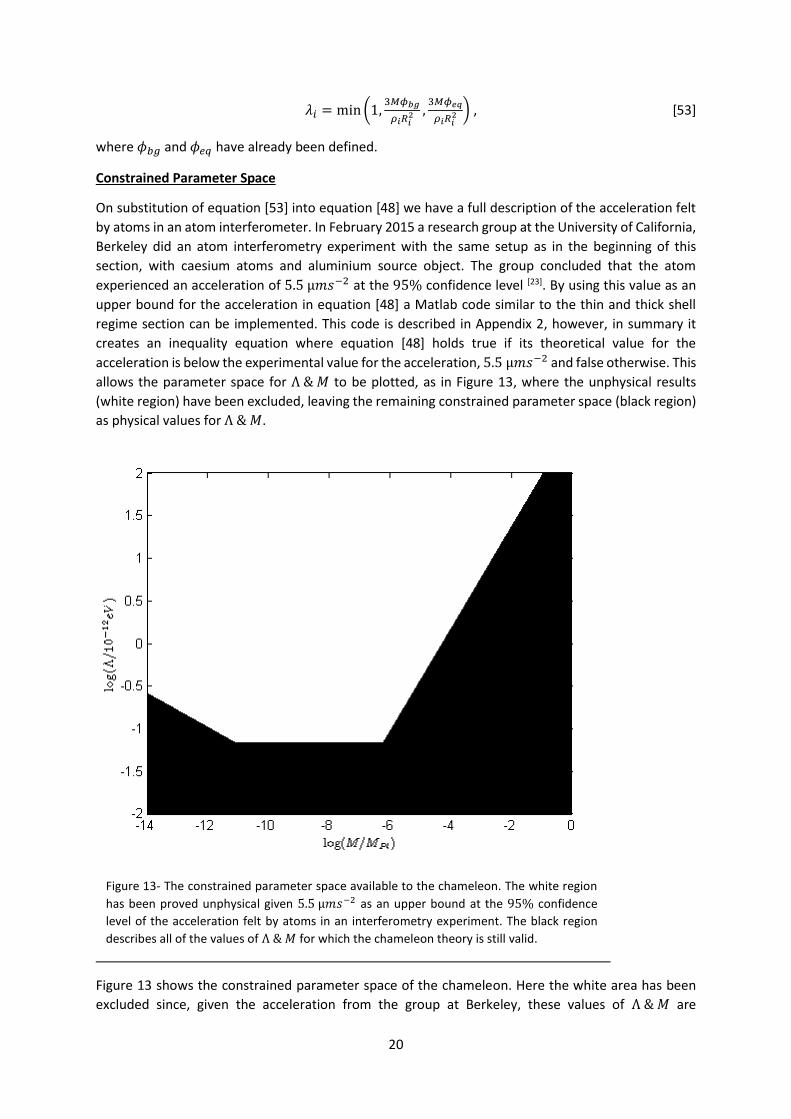
Constrained Parameter Space
On substitution of equation [53] into equation [48] we have a full description of the acceleration felt
by atoms in an atom interferometer. In February 2015 a research group at the University of California,
Berkeley did an atom interferometry experiment with the same setup as in the beginning of this
section, with caesium atoms and aluminium source object. The group concluded that the atom
experienced an acceleration of 5.5 µ𝑚𝑠−2 at the 95% confidence level [23]. By using this value as an
upper bound for the acceleration in equation [48] a Matlab code similar to the thin and thick shell
regime section can be implemented. This code is described in Appendix 2, however, in summary it
creates an inequality equation where equation [48] holds true if its theoretical value for the
acceleration is below the experimental value for the acceleration, 5.5 µ𝑚𝑠−2 and false otherwise. This
allows the parameter space for Λ & 𝑀 to be plotted, as in Figure 13, where the unphysical results
(white region) have been excluded, leaving the remaining constrained parameter space (black region)
as physical values for Λ & 𝑀.
Figure 13 shows the constrained parameter space of the chameleon. Here the white area has been
excluded since, given the acceleration from the group at Berkeley, these values of Λ & 𝑀 are
Figure 13- The constrained parameter space available to the chameleon. The white region
has been proved unphysical given 5.5 µ𝑚𝑠−2 as an upper bound at the 95% confidence
level of the acceleration felt by atoms in an interferometry experiment. The black region
describes all of the values of Λ & 𝑀 for which the chameleon theory is still valid.

21
unphysical. The remaining black region of the parameter plot is the area for which the values of Λ & 𝑀
are physical and thus still valid under the chameleon theory. As atom interferometry experiments
become more accurate the excluded region of the parameter space will become larger. Interferometry
experiments with lighter atoms (lithium for example) could improve the sensitivity of these results.
Furthermore, constraints on the ranges of Λ & 𝑀 could become more accurate, restricting the axis
and constraining the chameleon further. This constraining will continue until the theory has been
falsified, meaning the whole available parameter space is unphysical (white), or until there are a
distinct set of values for Λ & 𝑀 for which the chameleon theory is valid. As the precision of atom
interferometry increases there is the possibility that chameleon forces could be detected, these would
present themselves as an additional acceleration than a non-chameleon theory would predict (i.e.
without the second term in equation [48]). Thus being a smoking gun for the chameleon theory.
Conclusion
In summary, a scalar field describing dark energy has been introduced since the current accepted
model of dark energy in the Λ𝐶𝐷𝑀 model has a number of problems associated with it as it assumes
Λ is a constant. It has been proven that atoms do in fact have a thick shell in this description of the
chameleon through the use of a Matlab code. This code will determine whether any spherical object
in a given environment falls within the thin shell or the thick shell regime. Since atoms have a thick
shell it may be possible to detect chameleon forces by performing experiments on these atoms. With
this knowledge in mind it has been shown how atom interferometry can determine the acceleration
felt by atoms in the experiment. Finally, the acceleration from a recent atom interferometry
experiment has been used to impose, to date, the most accurate limits on the parameters Λ & 𝑀 in
the chameleon theory.
References
[1]- An Introduction to Galaxies and Cosmology. Jones, Mark H., Robert J. Lambourne (2004). Cambridge University Press. p. 244. ISBN 978-0-521-83738-5 [2]- http://www.bbc.co.uk/news/science-environment-15165371, "Nobel physics prize honours accelerating Universe find". BBC News. 4th October 2011. [3]- HongSheng Zhao, Anaelle Halle, Baojiu Li, 2008, "Perturbations in a non-uniform dark energy fluid: equations reveal effects of modified gravity and dark matter” [4]- D Hajdukovic, Quantum vacuum and virtual gravitational dipoles: the solution to the dark energy problem, Astrophysics and Space Science 339(1), 1-5, 2012 [5]- Ratra, Bharat & Peebles, P. J. E. 2003, "The cosmological constant and dark energy". Reviews of Modern Physics 75 (2): 559–606. arXiv:astro-ph/0207347, Bibcode:2003RvMP.75.559P, doi:10.1103/RevModPhys.75.559 [6]- Ade, P. A. R.; et al. (Planck Collaboration) 22 March 2013, "Planck 2013 results. I. Overview of products and scientific results – Table 9." Astronomy and Astrophysics. arXiv:1303.5062.Bibcode:2014A&A.571A.1P, doi:10.1051/0004-6361/201321529 [7]- Carroll, Sean, 2001. "The cosmological constant", Living Reviews in Relativity 4. [8]- Einstein, A (1917). "Kosmologische Betrachtungen zur allgemeinen Relativitaetstheorie". Sitzungsberichte der Königlich Preussischen Akademie der Wissenschaften Berlin. part 1: 142–152 [9]- General Relativity: An introduction for physicists, MP Hobson, GP Efstathiou & AN Lasenby (2006). Cambridge University Press. p. 187.ISBN 978-0-521-82951-9 [10]- Rugh, S, 2001 "The Quantum Vacuum and the Cosmological Constant Problem". Studies in History and Philosophy of Modern Physics 33 (4): 663–705.doi:10.1016/S1355-2198(02)00033-3 [11]- Christopher Wanjek; "Quintessence, accelerating the Universe?" http://www.astronomytoday.com/cosmology/quintessence.html

22
[12]- J. Khoury and A. Weltman, Phys. Rev. D 69, 044026 (2004) [13]- Torsion balance experiments: A low-energy frontier of particle physics, E.G. Adelberger, Center for Experimental Nuclear Physics and Astrophysics, 20 August 2008, doi:10.1016/j.ppnp.2008.08.002 [14]- Bunch, Bryan H; Hellemans, Alexander (April 2004). The History of Science and Technology. Houghton Mifflin Harcourt. p. 695. ISBN 978-0-618-22123-3 [15]- On the relative motion of earth and the luminiferous ether; by Michelson and Morley [16]- Dimopoulos, et al. "Gravitational wave detection with atom interferometry" PL B 678, 1 (2008). [17]- Testing General Relativity with Atom Interferometry, Savas Dimopoulos, Peter W. Graham, Jason M. Hogan, and Mark A. Kasevich, February 6, 2008, arXiv:gr-qc/0610047v2 [18]- Chameleon Cosmology, Khoury and Weltman, 1 Dec 2003, arXiv:astro-ph/0309411v2 [19]- Probing Dark Energy with Atom Interferometry, Clare Burrage, Edmund J. Copeland, and E. A. Hinds, 6 Aug 2014, arXiv:1408.1409v1 [astro-ph.CO] [20]- Upadhye, Dark energy fifth forces in torsion pendulum experiments. Phys. Rev. D 86, 102003 [21]- Burrage, C. Atomic precision tests and light scalar couplings. Phys. Rev. D 83, 035020 (2011). [22]- Jain, B., Vikram, V. & Sakstein, J. Astrophysical tests of modified gravity: Constraints from distance indicators in the nearby universe. Astrophys. J. 779, 39 (2013). [23]- P. Hamilton et al. Atom-interferometry constraints on dark energy, arXiv:1502.03888 (2015) [24]- P. Achim, High precision gravity measurements using atom interferometry, (1998) Appendix 1
Define range over which Λ & 𝑀 are possible
Link Λ & 𝑀 by using the 'meshgrid' command
Define an array, 𝑍 = Λ5 × 𝑀3 which
describes all points in the parameter space
Define the system; radius of source, mass of source,
local density
Take each value of Λ & 𝑀, substitute into
Δ𝑅𝑐
𝑅𝑐= 0.01 >
4
3
𝑍
𝜌∞
1
2 𝑅𝑐
𝑀𝑐
If equation is true return '1' and save in an array the same size and at the same
position as 𝑍
If equation is false return '0' and save in an array the same size and at the same
position as 𝑍
Plot this logical array to find the parameter plot for the specified system

23
Appendix 2
Define range over which Λ & 𝑀 are possible
Link Λ & 𝑀 by using the 'meshgrid' command
Define an array, 𝑍 = Λ5 × 𝑀3 which
describes all points in the parameter space
Define the system including vacuum
chamber dimensions and properties as well as
source and test particle
Find and save the values of 𝜆𝑎 & 𝜆𝑠 at each point of
𝑍 by using the function 'min' and applying it to the 3 possible values
Substitute the values for 𝜆𝑎 & 𝜆𝑠 into
𝑎 = 5.5𝜇𝑚𝑠−2 >𝐺𝑚𝑠
𝑟2 1 + 2𝜆𝑎𝜆𝑠𝑀𝑃𝑙
𝑀
2
If equation is true return '1' and save in an array
the same size and at the same position as 𝑍
If equation is false, return '0' and save in an array
the same size and at the same position as 𝑍
Plot this logical array to find the constrained
parameter space according to this
particular acceleration