four steps to building smarter satellite rf systems with
TRANSCRIPT
Four Steps to Building Smarter Satellite RF Systems with MATLAB
W H I T E PA P E R
Four Steps to Building Smarter Satellite RF Systems with MATLAB
W H I T E PA P E R | 2
Introduction
In this paper we present an approach for modeling and simulating RF systems that provides a more flexible and fluid design workflow than traditional methods With better modeling and simulation tools RF and communications engineers can rapidly develop ideas validate designs and build more robust RF systems
As communications satellites move toward high-throughput applications in geosynchronous medium Earth and low Earth orbits and as emphasis on mobility and new standards for mobile communica-tion increases RF front ends must become adaptive and agile in order to coexist mitigate against interfering signals and handle requirements such as
bull Efficient use of available spectrum
bull Standards for higher data rates and lower latency
bull Lower power consumption
These requirements as well as advances in device integration are causing RF front ends to become highly complex adaptive systems As a result RF system design is no longer an art that you can per-form in isolation System-level models that integrate RF and digital design can reduce risk and improve communication across engineering teams
Consider the common challenge of meeting requirements that change several times in the design cycle Design engineers can use these system-level models to capture requirements in executable spec-ifications They can explore ideas and tradeoffs optimize system performance and better communi-cate with customers and suppliers A unified RF system modeling and simulation environment enables faster design iterations and fewer design errors which directly translate to competitive advantages
Current Workflows Existing Tools and Their Limitations
Currently RF system architects use spreadsheets to perform initial calculations capture the high level specifications and evaluate power and noise budget and explore the frequency plan with simple equa-tions However static spreadsheets soon grow into monsters of macros used to cover many different scenarios These spreadsheets often include tabs and layers of complex computations that rely on hard-to-validate assumptions The spreadsheet method is difficult to maintain and share across a large organization and multiple projects For this reason many system architects switch to MATLABreg for greater clarity and control
While MATLAB is well known for scripting automation and signal processing it also offers tools for RF system design and analysis These tools provide accurate estimates of RF effects and impairments within adaptive architectures as well as automated creation of behavioral models for simulation This workflow allows you to develop and validate designs more rapidly and debug problems before build-ing hardware prototypes
Four Steps to Building Smarter Satellite RF Systems with MATLAB
W H I T E PA P E R | 3
How Better Tools for Modeling and Simulation Help Designers
The first step in this workflow is to simulate the full system including accurate models of the RF effects This approach overcomes limitations of traditional approaches to RF design and simulation For example
bull Abstract models of the RF behavior such as equivalent baseband [1] are not sufficient because they cannot be used to explore direct conversion architectures and to anticipate the effects of out-of-band interferers
bull Transient simulation is relatively easy to set up and understand but is too slow to encompass the simulation of the full RF front end Traditional circuit design tools do not offer the simulation performance necessary for system-level design
bull Dedicated RF simulation tools are suitable for RF experts but are hard for system architects and digital communications engineers to set up
System engineers need fast simulation tools that are suitable for complex architectures including signal processing algorithms and control logic while accurately accounting for RF effects These tools close the loop between system and RF design during specification implementation verification lab prototyping and testing
MATLAB and Simulink for RF System Design
In the following sections we illustrate this workflow using MATLAB and Simulinkreg for designing an RF receiver We start with the specifications and analysis of the receiver and show how to refine the front-end architecture with a model that includes control algorithms and an accurate description of the RF impairments
We conclude by modeling and simulating the Analog Devicesreg AD9361 transceiver The AD9361 [2] is an agile high-performance RF transceiver that transmits and receives wideband wireless signals ranging from 70 MHz to 60 GHz This general-purpose high-speed analog module is used for soft-ware-designed radio applications MIMO radio point-to-point communication systems femtocellPico cellmicrocell base stations Wi-Fi and ISM applications
The workflow consists of four major stages (Figure 1)
1) Static RF budget analysis
2) Design of RF architecture
3) System integration
4) Validation with measured data
Four Steps to Building Smarter Satellite RF Systems with MATLAB
W H I T E PA P E R | 4
Figure 1 Design workflow implemented with MATLAB and Simulink Starting from the specifications you can refine the RF model to include control and baseband algorithms and validate the simulation results against lab measurements
Static RF Budget Analysis
You begin by designing an RF receiver from its specifications Instead of using a spreadsheet you can use the RF Budget Analyzer app in RF Toolboxtrade [3] to analyze the noise power and linearity budget of the receiver and to evaluate different scenarios and operating conditions This app allows you to analyze the RF receiver using drag-and-drop blocks If you do not want to build the receiver from scratch you can use the receiver template that the app provides This app eliminates the need for custom spreadsheets to calculate the RF budget of your system [4]
The RF Budget Analyzer app does static RF analysis of the chain at a single frequency This analysis includes output frequency output power gain noise figure output-referred third-order intercept point (OIP3) and signal-to-noise ratio (SNR) The app computes the noise and power budget taking into account impedance mismatches between the blocks this allows you to examine different realistic configurations For example you can select and evaluate third-party off-the-shelf components using S-parameters derived from vendorsrsquo data sheets or from measurements
You can use the graphical interface of the RF Budget Analyzer app to design the RF transceivers or use a MATLAB script to automate the analysis for multiple scenarios You can generate a MATLAB
Four Steps to Building Smarter Satellite RF Systems with MATLAB
W H I T E PA P E R | 5
script from the app (Figure 2) You can also visualize a chain that has been scripted in MATLAB using the app This approach enables you to rapidly explore different what-if scenarios perform corner analysis or optimize the chain You can also define a multi-objective cost function and use Optimization Toolboxtrade to find the optimal parameters for the RF chain
Figure 2 RF budget analysis using the RF Budget Analyzer app (left) and automatically generated MATLAB code (right)
Design of RF Front-End Architecture
Once you are satisfied with the static budget analysis you can automatically generate an RF Blocksettrade [5] model from the receiver constructed using the RF Budget Analyzer app The model block diagram represents the architecture of the receiver using superheterodyne and homodyne architectures depending on the value of the intermediate frequency (Figure 3)
RF Blockset provides fast multicarrier circuit envelope [6] simulation of RF behavioral models that execute within a time-domain system-level Simulink simulation The automatic generation of the RF model allows you to rapidly get started with circuit envelope simulation and guarantees consistency between analytical computations and simulation results You can simulate a multi-carrier frequency system with realistic complexities in the time domain to go beyond purely analytical computations
You can use the circuit envelope approach to simulate the receiver behavior in different configura-tions and scenarios This workflow allows you to iterate more rapidly from specifications to architec-ture definition and to take into account scenarios that are otherwise difficult to anticipate Circuit envelope simulation leverages harmonic balance technology to simulate the effects of odd- and even-order non-linearity reciprocal mixing and in-band and out-of-band interfering signals
Four Steps to Building Smarter Satellite RF Systems with MATLAB
W H I T E PA P E R | 6
Figure 3 RF Blockset circuit envelope model that represents a direct conversion receiver The quadrature architecture has been auto-matically generated from the RF Budget Analyzer app
Verification of RF Performance and Model Refinement
You can also produce a measurement test bench from the RF Budget Analyzer to simplify the valida-tion of your design (Figure 4) The measurement test bench is a Simulink model that produces a stim-ulus to test the performance of the receiver which is the device under test or DUT To validate your system the test bench lets you compares the values of Gain Noise Figure and OIP3 in the simulation and make sure they are the same For example the test bench allows you to verify that your receiver is operating correctly in mildly nonlinear conditions
With circuit envelope simulation you can elaborate your model to include a more detailed descrip-tion of the RF effects compared with the analytical results You can use the same test bench to verify aspects of performance that are hard to validate analytically such as IP2 DC offset and image rejec-tion This approach allows you to further elaborate the model and include impairments such as even-order nonlinearity LO leakage and I and Q imbalance
The test bench reproduces the lab conditions for testing a device For example the performance of a direct conversion receiver can be measured on the I or Q branch at an arbitrary low frequency Without the automatic model and test bench generation users are required to repeat over and over again the manual task of describing the desired architecture and validating its performance This approach greatly simplifies the design process of linking the paper specifications to an architecturally correct executable model
Figure 4 Test bench automatically generated from the RF Budget Analyzer app to validate the receiver performance
Four Steps to Building Smarter Satellite RF Systems with MATLAB
W H I T E PA P E R | 7
System Integration
RF system simulation using Simulink and RF Blockset is unique because it enables you to place the RF model into a full system simulation You can integrate signal processing algorithms and control logic with the RF front-end model to calibrate and compensate for RF impairments For example you can stream a baseband-modulated signal though your RF receiver and evaluate the received constel-lation and error vector magnitude By simulating testing and validating the entire receiver you can understand how the full system works without relying exclusively on the paper documentation and lab measurements Not only do you gain confidence in the design but also a better understanding of the lab testing conditions for the device
As an example the model [7] in Figure 5 represents the executable specifications of the AD9361 and accurately predicts the timing and spectral performance of the transceiver The model transparently reproduces the actual chip architecture By exposing internal nodes that are otherwise not accessible in a single-chip solution the model provides insightful metrics The model parameters have the same name as the chip registers allowing you to rapidly configure the system using simulation The alter-native is to rely on over specification and expensive lab testing later in the development process
Figure 5 Receiver architecture of the Analog Devices AD9361 The feedback loop implements the automatic gain control based on the received signal strength
Four Steps to Building Smarter Satellite RF Systems with MATLAB
W H I T E PA P E R | 8
The Simulink block diagram reproduces the diagram specification depicted in the AD9361 data sheet The model of the signal path includes
bull The RF front end that performs direct conversion from RF to analog baseband
bull A programmable analog filter
bull A third order delta sigma ADC
bull Four programmable multirate multistage down-conversion filters
The RF front end has been modeled using blocks from the Circuit Envelope library in RF Blockset to accurately take into account the RF effects and achieve fast simulation The receiver (Figure 6) con-sists of three stages the low noise amplifier (LNA) the quadrature demodulator and the trans imped-ance amplifier (TIA) Each of these stages has tunable gains that are controlled by the AGC state machine The model of the RF front end is directly based on the elaboration of the architectural model described in the previous section
Figure 6 Model of the Analog Devices AD9361 direct conversion RF receiver The model is based on the elaboration of a quadra-ture receiver where variable gain amplifiers have been used to simulate adaptive gain stages
A state machine modeled with Stateflowreg represents the programmable control logic used to automat-ically adjust the gain (AGC) The AGC comes with three modes of operation Slow Attack Fast Attack and Manual The different attack modes of the model reproduce the actual AGC timing
The AGC feedback loop ensures that signals do not saturate the model at one of three points output of the RF front end output of the ADC and output of the down-conversion filters This approach keeps the system operating with optimal linearity even in the presence of interfering signals Power meters detect the signal levels at three points of the data path for example the peak detector after the RF front end allows the system to immediately react in presence of interferers while the power meter after the down-conversion filters has a longer timing dynamic and allows the system to settle the average signal power within the desired range
Four Steps to Building Smarter Satellite RF Systems with MATLAB
W H I T E PA P E R | 9
You can use the AD9361 transceiver model to simulate the chip behavior when receiving an LTE signal and assess the receiver performance in different scenarios and configurations For example you can specify different filter configurations taking into account narrowband and wideband inter-fering signals with different power levels With LTE System Toolboxtrade you can generate standard-com-pliant LTE reference signals and measure the transceiver EVM and ACLR or test fast and slow gain-control modes in conjunction with TDD and FDD signals (Figure 7)
Figure 7 Test bench for testing an Analog Devices AD9371 receiver with an LTE-compliant signal in the presence of an adjacent in-band wideband interfering signal
Model Validation with Measured Data
The RF front end model has been initially developed with the RF Budget Analyzer app extended to include a more detailed description of the impairments and validated with the automatically generat-ed test bench Measurements from the actual device have been embedded in the refined model in the form of look-up tables providing accurate results
A multidimensional look-up table that is a function of the instantaneous gains setting allows you to simulate the system IP3 IP2 DC offset and IQ imbalance When the gain changes the actual impairments also change thus predicting the actual system performance The look-up table with the input-referred impairments was measured in the lab by Analog Devices The table is interpolated to provide accurate results in all operating conditions
Four Steps to Building Smarter Satellite RF Systems with MATLAB
W H I T E PA P E R | 1 0
By using the circuit envelope solver within a system-level simulation accurate results can be obtained without compromising simulation speed On a Lenovo T450s laptop the model simulates 1ms of data in approximately 20 seconds of real time enabling processing of entire LTE frames This simulation speed and level of accuracy is unachievable with traditional tools
The AD9361 model employs a top-down design methodology to achieve bottom-up verification The model provides visibility into the device architecture and signal path During the development pro-cess details can be added to progressively refine the model Initially the model used nominal specifi-cations and through iteration the model becomes more accurate by embedding parameters determined through system simulation and the device measurements You can use the AD9361 model to configure the numerous device registers rather than spending time in the lab building test condi-tions that are hard to reproduce
Conclusion
MATLAB and Simulink provide an easy-to-use flexible and end-to-end workflow that helps you keep up with advances requirements and challenges in RF system design and verification RF Blockset helps you analyze simulate and test an RF system before manufacturing it With RF Toolbox and its RF Budget Analyzer app you can calculate the RF budget to confirm the basic speci-fications required to design the system Using RF Blockset you can simulate the entire RF front-end architecture including interfering scenarios and coexistence with other systems Once you have simu-lated your RF architecture you can validate it using the measurement test benches and further elabo-rate the model to explore scenarios evaluate design choices and debug prototyping problems in realistic conditions
Models of Analog Devices transceiver chips available with RF Blockset provide an example of these capabilities You can download models of the agile transceiver AD9361 and wideband transceiver AD9371 from mathworkscom to develop cutting-edge system-level models to share with your col-leagues suppliers and customers With the comprehensive and expressive modeling solution these tools provide you can simulate end-to-end wireless communication systems that embed sophisticated control logic and highly adaptive signal processing algorithms
Four Steps to Building Smarter Satellite RF Systems with MATLAB
W H I T E PA P E R | 1 1
copy 2018 The MathWorks Inc MATLAB and Simulink are registered trademarks of The MathWorks Inc See mathworkscomtrademarks for a list of additional trademarks Other product or brand names may be trademarks or registered trademarks of their respective holders
References
[1] Create a Complex Baseband-Equivalent Model with RF Blockset mathworkscomhelpsimrfugcreate-a-complex-baseband-equivalent-modelhtml
[2] AD9361 Reference Manual - httpwwwanalogcommediaentechnical-documentationuser-guidesAD9361_Reference_Manual_UG-570pdf
[3] RF Toolbox - mathworkscomproductsrftoolbox
[4] RF Budget Analyzer App - mathworkscomhelprfugrfbudgetanalyzer-apphtml
[5] RF Blockset - mathworkscomproductsrfblockset
[6] Circuit Envelope Fundamentals Simulate High Frequency Components with RF Blockset - mathworkscomhelpsimrfgsminimize-computations-for-rf-simulationshtml
[7] Download RF Blockset Models of Analog Devices Transceivers mathworkscomhardware-supportanalog-devices-rf-transceivershtml
Learn More
User Story Lockheed Martin Develops Configurable Space-Qualified Digital Channelizer
Webinar Design of Wireless MIMO Systems From RF Specifications to Architecture Exploration
Code Examples Superheterodyne Receiver Using RF Budget Analyzer App
Overview CubeSat
Request Trial Wireless Communications

Four Steps to Building Smarter Satellite RF Systems with MATLAB
W H I T E PA P E R | 6
Figure 3 RF Blockset circuit envelope model that represents a direct conversion receiver The quadrature architecture has been auto-matically generated from the RF Budget Analyzer app
Verification of RF Performance and Model Refinement
You can also produce a measurement test bench from the RF Budget Analyzer to simplify the valida-tion of your design (Figure 4) The measurement test bench is a Simulink model that produces a stim-ulus to test the performance of the receiver which is the device under test or DUT To validate your system the test bench lets you compares the values of Gain Noise Figure and OIP3 in the simulation and make sure they are the same For example the test bench allows you to verify that your receiver is operating correctly in mildly nonlinear conditions
With circuit envelope simulation you can elaborate your model to include a more detailed descrip-tion of the RF effects compared with the analytical results You can use the same test bench to verify aspects of performance that are hard to validate analytically such as IP2 DC offset and image rejec-tion This approach allows you to further elaborate the model and include impairments such as even-order nonlinearity LO leakage and I and Q imbalance
The test bench reproduces the lab conditions for testing a device For example the performance of a direct conversion receiver can be measured on the I or Q branch at an arbitrary low frequency Without the automatic model and test bench generation users are required to repeat over and over again the manual task of describing the desired architecture and validating its performance This approach greatly simplifies the design process of linking the paper specifications to an architecturally correct executable model
Figure 4 Test bench automatically generated from the RF Budget Analyzer app to validate the receiver performance
Four Steps to Building Smarter Satellite RF Systems with MATLAB
W H I T E PA P E R | 7
System Integration
RF system simulation using Simulink and RF Blockset is unique because it enables you to place the RF model into a full system simulation You can integrate signal processing algorithms and control logic with the RF front-end model to calibrate and compensate for RF impairments For example you can stream a baseband-modulated signal though your RF receiver and evaluate the received constel-lation and error vector magnitude By simulating testing and validating the entire receiver you can understand how the full system works without relying exclusively on the paper documentation and lab measurements Not only do you gain confidence in the design but also a better understanding of the lab testing conditions for the device
As an example the model [7] in Figure 5 represents the executable specifications of the AD9361 and accurately predicts the timing and spectral performance of the transceiver The model transparently reproduces the actual chip architecture By exposing internal nodes that are otherwise not accessible in a single-chip solution the model provides insightful metrics The model parameters have the same name as the chip registers allowing you to rapidly configure the system using simulation The alter-native is to rely on over specification and expensive lab testing later in the development process
Figure 5 Receiver architecture of the Analog Devices AD9361 The feedback loop implements the automatic gain control based on the received signal strength
Four Steps to Building Smarter Satellite RF Systems with MATLAB
W H I T E PA P E R | 8
The Simulink block diagram reproduces the diagram specification depicted in the AD9361 data sheet The model of the signal path includes
bull The RF front end that performs direct conversion from RF to analog baseband
bull A programmable analog filter
bull A third order delta sigma ADC
bull Four programmable multirate multistage down-conversion filters
The RF front end has been modeled using blocks from the Circuit Envelope library in RF Blockset to accurately take into account the RF effects and achieve fast simulation The receiver (Figure 6) con-sists of three stages the low noise amplifier (LNA) the quadrature demodulator and the trans imped-ance amplifier (TIA) Each of these stages has tunable gains that are controlled by the AGC state machine The model of the RF front end is directly based on the elaboration of the architectural model described in the previous section
Figure 6 Model of the Analog Devices AD9361 direct conversion RF receiver The model is based on the elaboration of a quadra-ture receiver where variable gain amplifiers have been used to simulate adaptive gain stages
A state machine modeled with Stateflowreg represents the programmable control logic used to automat-ically adjust the gain (AGC) The AGC comes with three modes of operation Slow Attack Fast Attack and Manual The different attack modes of the model reproduce the actual AGC timing
The AGC feedback loop ensures that signals do not saturate the model at one of three points output of the RF front end output of the ADC and output of the down-conversion filters This approach keeps the system operating with optimal linearity even in the presence of interfering signals Power meters detect the signal levels at three points of the data path for example the peak detector after the RF front end allows the system to immediately react in presence of interferers while the power meter after the down-conversion filters has a longer timing dynamic and allows the system to settle the average signal power within the desired range
Four Steps to Building Smarter Satellite RF Systems with MATLAB
W H I T E PA P E R | 9
You can use the AD9361 transceiver model to simulate the chip behavior when receiving an LTE signal and assess the receiver performance in different scenarios and configurations For example you can specify different filter configurations taking into account narrowband and wideband inter-fering signals with different power levels With LTE System Toolboxtrade you can generate standard-com-pliant LTE reference signals and measure the transceiver EVM and ACLR or test fast and slow gain-control modes in conjunction with TDD and FDD signals (Figure 7)
Figure 7 Test bench for testing an Analog Devices AD9371 receiver with an LTE-compliant signal in the presence of an adjacent in-band wideband interfering signal
Model Validation with Measured Data
The RF front end model has been initially developed with the RF Budget Analyzer app extended to include a more detailed description of the impairments and validated with the automatically generat-ed test bench Measurements from the actual device have been embedded in the refined model in the form of look-up tables providing accurate results
A multidimensional look-up table that is a function of the instantaneous gains setting allows you to simulate the system IP3 IP2 DC offset and IQ imbalance When the gain changes the actual impairments also change thus predicting the actual system performance The look-up table with the input-referred impairments was measured in the lab by Analog Devices The table is interpolated to provide accurate results in all operating conditions
Four Steps to Building Smarter Satellite RF Systems with MATLAB
W H I T E PA P E R | 1 0
By using the circuit envelope solver within a system-level simulation accurate results can be obtained without compromising simulation speed On a Lenovo T450s laptop the model simulates 1ms of data in approximately 20 seconds of real time enabling processing of entire LTE frames This simulation speed and level of accuracy is unachievable with traditional tools
The AD9361 model employs a top-down design methodology to achieve bottom-up verification The model provides visibility into the device architecture and signal path During the development pro-cess details can be added to progressively refine the model Initially the model used nominal specifi-cations and through iteration the model becomes more accurate by embedding parameters determined through system simulation and the device measurements You can use the AD9361 model to configure the numerous device registers rather than spending time in the lab building test condi-tions that are hard to reproduce
Conclusion
MATLAB and Simulink provide an easy-to-use flexible and end-to-end workflow that helps you keep up with advances requirements and challenges in RF system design and verification RF Blockset helps you analyze simulate and test an RF system before manufacturing it With RF Toolbox and its RF Budget Analyzer app you can calculate the RF budget to confirm the basic speci-fications required to design the system Using RF Blockset you can simulate the entire RF front-end architecture including interfering scenarios and coexistence with other systems Once you have simu-lated your RF architecture you can validate it using the measurement test benches and further elabo-rate the model to explore scenarios evaluate design choices and debug prototyping problems in realistic conditions
Models of Analog Devices transceiver chips available with RF Blockset provide an example of these capabilities You can download models of the agile transceiver AD9361 and wideband transceiver AD9371 from mathworkscom to develop cutting-edge system-level models to share with your col-leagues suppliers and customers With the comprehensive and expressive modeling solution these tools provide you can simulate end-to-end wireless communication systems that embed sophisticated control logic and highly adaptive signal processing algorithms
Four Steps to Building Smarter Satellite RF Systems with MATLAB
W H I T E PA P E R | 1 1
copy 2018 The MathWorks Inc MATLAB and Simulink are registered trademarks of The MathWorks Inc See mathworkscomtrademarks for a list of additional trademarks Other product or brand names may be trademarks or registered trademarks of their respective holders
References
[1] Create a Complex Baseband-Equivalent Model with RF Blockset mathworkscomhelpsimrfugcreate-a-complex-baseband-equivalent-modelhtml
[2] AD9361 Reference Manual - httpwwwanalogcommediaentechnical-documentationuser-guidesAD9361_Reference_Manual_UG-570pdf
[3] RF Toolbox - mathworkscomproductsrftoolbox
[4] RF Budget Analyzer App - mathworkscomhelprfugrfbudgetanalyzer-apphtml
[5] RF Blockset - mathworkscomproductsrfblockset
[6] Circuit Envelope Fundamentals Simulate High Frequency Components with RF Blockset - mathworkscomhelpsimrfgsminimize-computations-for-rf-simulationshtml
[7] Download RF Blockset Models of Analog Devices Transceivers mathworkscomhardware-supportanalog-devices-rf-transceivershtml
Learn More
User Story Lockheed Martin Develops Configurable Space-Qualified Digital Channelizer
Webinar Design of Wireless MIMO Systems From RF Specifications to Architecture Exploration
Code Examples Superheterodyne Receiver Using RF Budget Analyzer App
Overview CubeSat
Request Trial Wireless Communications
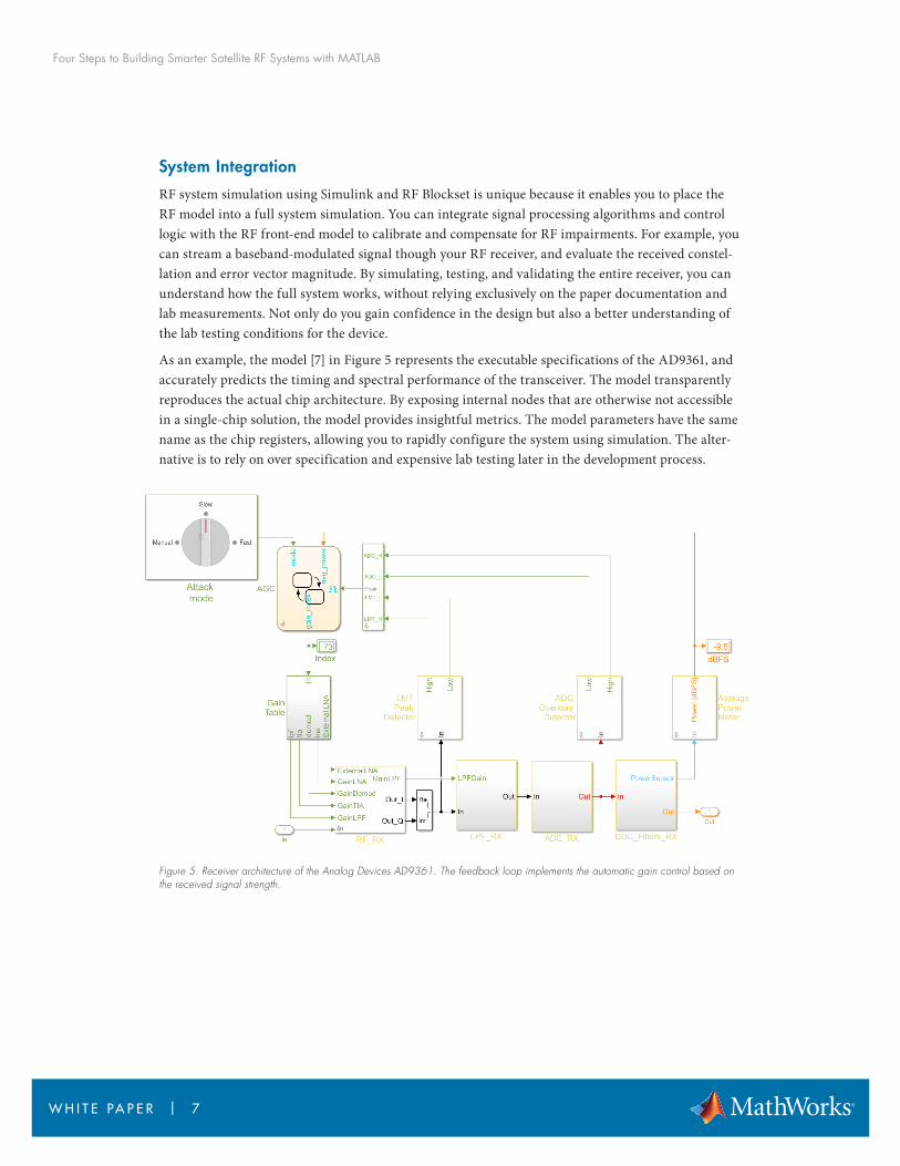
Four Steps to Building Smarter Satellite RF Systems with MATLAB
W H I T E PA P E R | 8
The Simulink block diagram reproduces the diagram specification depicted in the AD9361 data sheet The model of the signal path includes
bull The RF front end that performs direct conversion from RF to analog baseband
bull A programmable analog filter
bull A third order delta sigma ADC
bull Four programmable multirate multistage down-conversion filters
The RF front end has been modeled using blocks from the Circuit Envelope library in RF Blockset to accurately take into account the RF effects and achieve fast simulation The receiver (Figure 6) con-sists of three stages the low noise amplifier (LNA) the quadrature demodulator and the trans imped-ance amplifier (TIA) Each of these stages has tunable gains that are controlled by the AGC state machine The model of the RF front end is directly based on the elaboration of the architectural model described in the previous section
Figure 6 Model of the Analog Devices AD9361 direct conversion RF receiver The model is based on the elaboration of a quadra-ture receiver where variable gain amplifiers have been used to simulate adaptive gain stages
A state machine modeled with Stateflowreg represents the programmable control logic used to automat-ically adjust the gain (AGC) The AGC comes with three modes of operation Slow Attack Fast Attack and Manual The different attack modes of the model reproduce the actual AGC timing
The AGC feedback loop ensures that signals do not saturate the model at one of three points output of the RF front end output of the ADC and output of the down-conversion filters This approach keeps the system operating with optimal linearity even in the presence of interfering signals Power meters detect the signal levels at three points of the data path for example the peak detector after the RF front end allows the system to immediately react in presence of interferers while the power meter after the down-conversion filters has a longer timing dynamic and allows the system to settle the average signal power within the desired range
Four Steps to Building Smarter Satellite RF Systems with MATLAB
W H I T E PA P E R | 9
You can use the AD9361 transceiver model to simulate the chip behavior when receiving an LTE signal and assess the receiver performance in different scenarios and configurations For example you can specify different filter configurations taking into account narrowband and wideband inter-fering signals with different power levels With LTE System Toolboxtrade you can generate standard-com-pliant LTE reference signals and measure the transceiver EVM and ACLR or test fast and slow gain-control modes in conjunction with TDD and FDD signals (Figure 7)
Figure 7 Test bench for testing an Analog Devices AD9371 receiver with an LTE-compliant signal in the presence of an adjacent in-band wideband interfering signal
Model Validation with Measured Data
The RF front end model has been initially developed with the RF Budget Analyzer app extended to include a more detailed description of the impairments and validated with the automatically generat-ed test bench Measurements from the actual device have been embedded in the refined model in the form of look-up tables providing accurate results
A multidimensional look-up table that is a function of the instantaneous gains setting allows you to simulate the system IP3 IP2 DC offset and IQ imbalance When the gain changes the actual impairments also change thus predicting the actual system performance The look-up table with the input-referred impairments was measured in the lab by Analog Devices The table is interpolated to provide accurate results in all operating conditions
Four Steps to Building Smarter Satellite RF Systems with MATLAB
W H I T E PA P E R | 1 0
By using the circuit envelope solver within a system-level simulation accurate results can be obtained without compromising simulation speed On a Lenovo T450s laptop the model simulates 1ms of data in approximately 20 seconds of real time enabling processing of entire LTE frames This simulation speed and level of accuracy is unachievable with traditional tools
The AD9361 model employs a top-down design methodology to achieve bottom-up verification The model provides visibility into the device architecture and signal path During the development pro-cess details can be added to progressively refine the model Initially the model used nominal specifi-cations and through iteration the model becomes more accurate by embedding parameters determined through system simulation and the device measurements You can use the AD9361 model to configure the numerous device registers rather than spending time in the lab building test condi-tions that are hard to reproduce
Conclusion
MATLAB and Simulink provide an easy-to-use flexible and end-to-end workflow that helps you keep up with advances requirements and challenges in RF system design and verification RF Blockset helps you analyze simulate and test an RF system before manufacturing it With RF Toolbox and its RF Budget Analyzer app you can calculate the RF budget to confirm the basic speci-fications required to design the system Using RF Blockset you can simulate the entire RF front-end architecture including interfering scenarios and coexistence with other systems Once you have simu-lated your RF architecture you can validate it using the measurement test benches and further elabo-rate the model to explore scenarios evaluate design choices and debug prototyping problems in realistic conditions
Models of Analog Devices transceiver chips available with RF Blockset provide an example of these capabilities You can download models of the agile transceiver AD9361 and wideband transceiver AD9371 from mathworkscom to develop cutting-edge system-level models to share with your col-leagues suppliers and customers With the comprehensive and expressive modeling solution these tools provide you can simulate end-to-end wireless communication systems that embed sophisticated control logic and highly adaptive signal processing algorithms
Four Steps to Building Smarter Satellite RF Systems with MATLAB
W H I T E PA P E R | 1 1
copy 2018 The MathWorks Inc MATLAB and Simulink are registered trademarks of The MathWorks Inc See mathworkscomtrademarks for a list of additional trademarks Other product or brand names may be trademarks or registered trademarks of their respective holders
References
[1] Create a Complex Baseband-Equivalent Model with RF Blockset mathworkscomhelpsimrfugcreate-a-complex-baseband-equivalent-modelhtml
[2] AD9361 Reference Manual - httpwwwanalogcommediaentechnical-documentationuser-guidesAD9361_Reference_Manual_UG-570pdf
[3] RF Toolbox - mathworkscomproductsrftoolbox
[4] RF Budget Analyzer App - mathworkscomhelprfugrfbudgetanalyzer-apphtml
[5] RF Blockset - mathworkscomproductsrfblockset
[6] Circuit Envelope Fundamentals Simulate High Frequency Components with RF Blockset - mathworkscomhelpsimrfgsminimize-computations-for-rf-simulationshtml
[7] Download RF Blockset Models of Analog Devices Transceivers mathworkscomhardware-supportanalog-devices-rf-transceivershtml
Learn More
User Story Lockheed Martin Develops Configurable Space-Qualified Digital Channelizer
Webinar Design of Wireless MIMO Systems From RF Specifications to Architecture Exploration
Code Examples Superheterodyne Receiver Using RF Budget Analyzer App
Overview CubeSat
Request Trial Wireless Communications
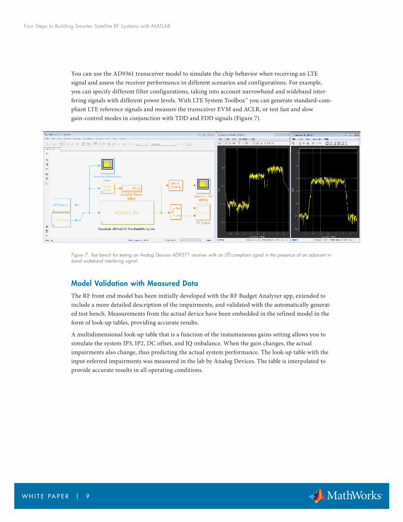
Four Steps to Building Smarter Satellite RF Systems with MATLAB
W H I T E PA P E R | 1 1
copy 2018 The MathWorks Inc MATLAB and Simulink are registered trademarks of The MathWorks Inc See mathworkscomtrademarks for a list of additional trademarks Other product or brand names may be trademarks or registered trademarks of their respective holders
References
[1] Create a Complex Baseband-Equivalent Model with RF Blockset mathworkscomhelpsimrfugcreate-a-complex-baseband-equivalent-modelhtml
[2] AD9361 Reference Manual - httpwwwanalogcommediaentechnical-documentationuser-guidesAD9361_Reference_Manual_UG-570pdf
[3] RF Toolbox - mathworkscomproductsrftoolbox
[4] RF Budget Analyzer App - mathworkscomhelprfugrfbudgetanalyzer-apphtml
[5] RF Blockset - mathworkscomproductsrfblockset
[6] Circuit Envelope Fundamentals Simulate High Frequency Components with RF Blockset - mathworkscomhelpsimrfgsminimize-computations-for-rf-simulationshtml
[7] Download RF Blockset Models of Analog Devices Transceivers mathworkscomhardware-supportanalog-devices-rf-transceivershtml
Learn More
User Story Lockheed Martin Develops Configurable Space-Qualified Digital Channelizer
Webinar Design of Wireless MIMO Systems From RF Specifications to Architecture Exploration
Code Examples Superheterodyne Receiver Using RF Budget Analyzer App
Overview CubeSat
Request Trial Wireless Communications