foundations of materials science and engineering lecture ... · pdf filekwangkim...
TRANSCRIPT

Kwang Kim
Yonsei University
Foundations of
Materials Science and Engineering
Lecture Note 4April 2, 2013
39
Y88.91
8
O16.00
53
I126.9
34
Se78.96
7
N14.01
Solidification of Metals
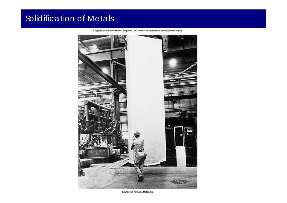
Solidification of Metals
The solidification of metals and their alloys is an important
industrial process. Not only do structural alloys start with the
casting of ingots for processing into reinforcing bars or structural
shapes, but when a metal is welded a small portion of metal near
the weld melts and resolidifies. It also serves as a model to
represent first order phase transformations in general.

Solidification of Metals
Metals are melted to produce finished and semi-finished parts.Two steps of solidification
Nucleation : Formation of stable nuclei. Growth of nuclei : Formation of grain structure.
Thermal gradients define the shape of each grain.
(a) Formation of stable nuclei (b) Growth of crystals (c) Grain structure
Solidification of Metals
Phase transformations involve change in structure and composition ⇒ rearrangement and redistribution of atoms via diffusion is
required.- Nucleation : Formation of stable nuclei. - Growth of nuclei : Formation of grain structure.
The process of phase transformation involves:- Nucleation of the new phase(s) - formation of stable small particles
(nuclei) of the new phase(s). Nuclei are often formed at grain boundaries and other defects.
- Growth of the new phase(s) at the expense of the originalphase(s).
Ideal Gas Law
An ideal gas :
‐ all collisions between atoms or molecules are perfectlyelastic‐ there are no intermolecular attractive forces‐ a collection of perfectly hard spheres which collide butwhich otherwise do not interact with each other‐ no potential energy (no force field)‐ all the internal energy is in the form of kinetic energyand any change in internal energy is accompanied by achange in temperature.
An ideal gas : characterized by three state variables: absolute pressure (P), volume (V), and absolute temperature (T).

Non- ideal Gas
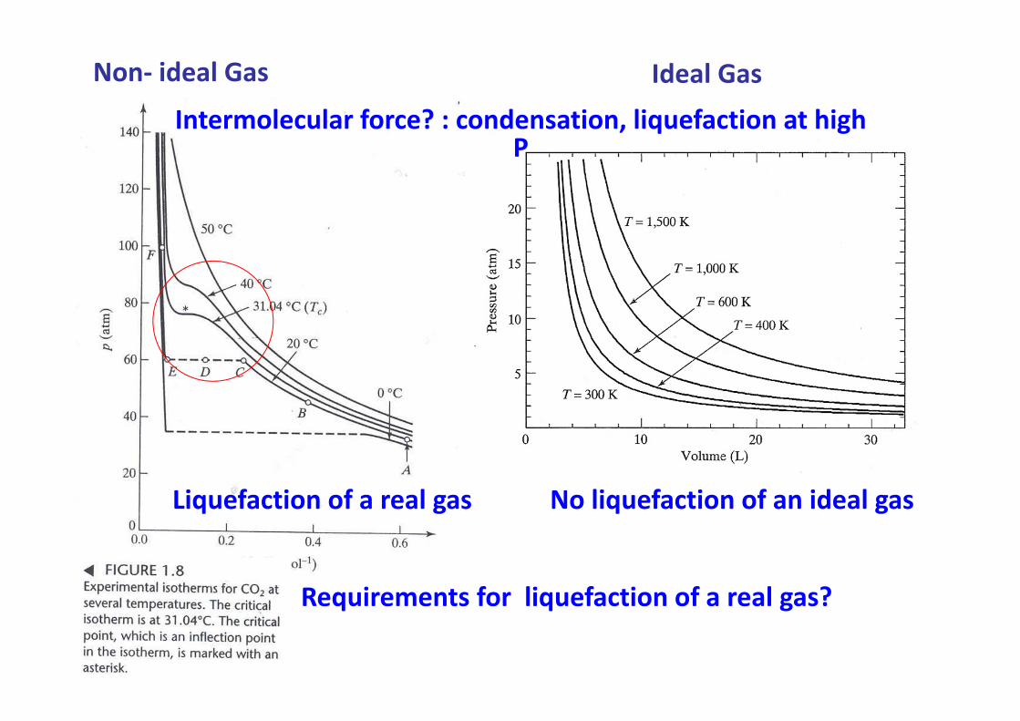
Non‐ ideal Gas Ideal Gas
No liquefaction of an ideal gasLiquefaction of a real gas
Intermolecular force? : condensation, liquefaction at high P
Requirements for liquefaction of a real gas?

Phase Equilibria in water
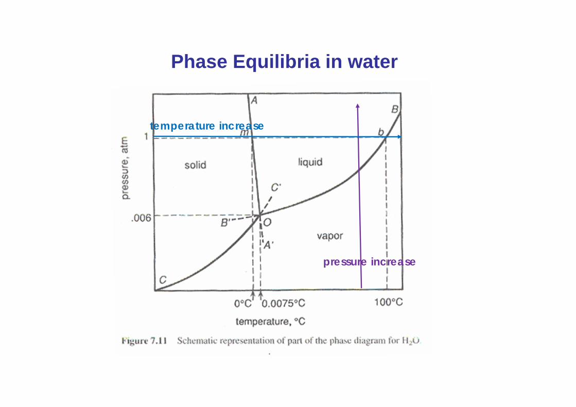
Phase Equilibria in water
pressure increase
temperature increase

Phase Equilibria in water
pressure increase
temperature increase
Temp.
time
S + L
S
L
L + V
V

Phase Equilibria in water
pressure increase
temperature increase
Pressure
time
V V +L L
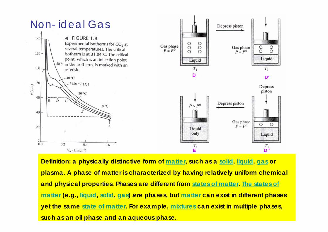
Non- ideal Gas
At point C
D
E D’’
D’
Definition: a physically distinctive form of matter, such as a solid, liquid, gas or
plasma. A phase of matter is characterized by having relatively uniform chemical
and physical properties. Phases are different from states of matter. The states of
matter (e.g., liquid, solid, gas) are phases, but matter can exist in different phases
yet the same state of matter. For example, mixtures can exist in multiple phases,
such as an oil phase and an aqueous phase.

Critical PointCritical Temperature TcCritical Pressure PcCritical Volume Vc
Molar volume of gas
Molar volume of liquid
At Critical Point,
Molar volume of liquid
= Molar volume of gas
Pc
Vc

Cryophorus : an instrument that illustrates the freezing of water by its own evaporation A cryophorus is a glass container containing liquid water and water vapor. It is used to demonstrate rapid freezing by evaporation. A typical cryophorus has a bulb at one end connected to a tube of the same material. When the liquid water is manipulated into the bulbed end and the other end is connected to a vacuum pump, the gas pressure drops as it is cooled. The liquid water begins to evaporate, producing more water vapor. Evaporation causes the water to cool rapidly to its freezing point and it solidifies suddenly. Finally, a piece of ice disappears as a result of ice sublimation to water vapor/
Vacuum pump
Water droplet in a bottle under vacuum
*
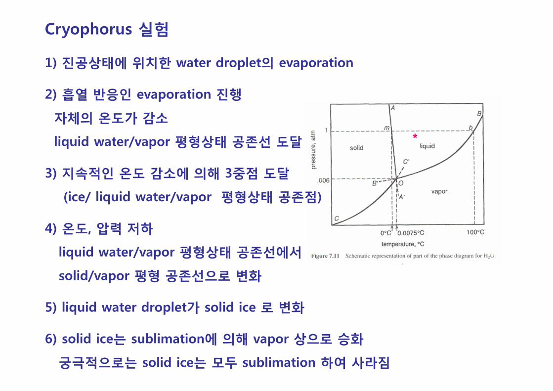
Cryophorus 실험
1) 진공상태에 위치한 water droplet의 evaporation
2) 흡열 반응인 evaporation 진행
자체의 온도가 감소
liquid water/vapor 평형상태 공존선 도달
3) 지속적인 온도 감소에 의해 3중점 도달
(ice/ liquid water/vapor 평형상태 공존점)
4) 온도, 압력 저하
liquid water/vapor 평형상태 공존선에서
solid/vapor 평형 공존선으로 변화
5) liquid water droplet가 solid ice 로 변화
6) solid ice는 sublimation에 의해 vapor 상으로 승화
궁극적으로는 solid ice는 모두 sublimation 하여 사라짐
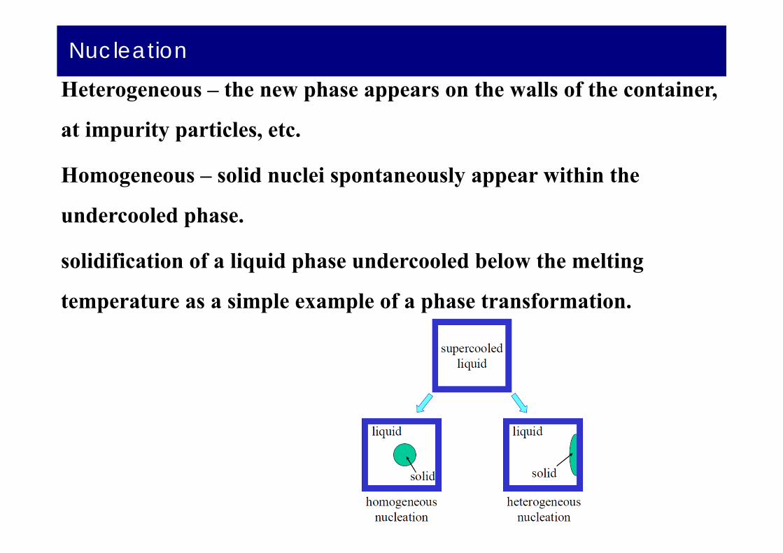
Nucleation
Heterogeneous – the new phase appears on the walls of the container,
at impurity particles, etc.
Homogeneous – solid nuclei spontaneously appear within the
undercooled phase.
solidification of a liquid phase undercooled below the melting
temperature as a simple example of a phase transformation.

Homogenous Nucleation
Homogeneous nucleation occurs when there are no special objects inside a phase which can cause nucleation.For instance when a pure liquid metal is slowly cooled below its equilibrium freezing temperature to a sufficient degree numerous homogeneous nuclei are created by slow-moving atoms bonding together in a crystalline form.
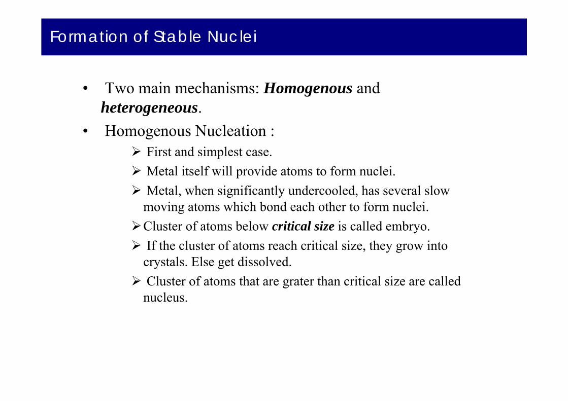
Formation of Stable Nuclei
• Two main mechanisms: Homogenous and heterogeneous.
• Homogenous Nucleation : First and simplest case. Metal itself will provide atoms to form nuclei. Metal, when significantly undercooled, has several slow
moving atoms which bond each other to form nuclei. Cluster of atoms below critical size is called embryo. If the cluster of atoms reach critical size, they grow into
crystals. Else get dissolved. Cluster of atoms that are grater than critical size are called
nucleus.

Solidification of Metals
Typical data relevant to the solidification of metals
Gibbs Free Energy
G = H - TS
where H = Enthalpy, T = Absolute Temperature, and S = Entropy
Materials Scientists refer to the difference in G between the old
and new phases as the driving “force” for the phase transformation.
The release of heat when a metal solidifies indicates that the
crystalline phase has a lower Gibbs Free Energy, G, than the liquid.
At the equilibrium freezing temperature the Gibbs Free Energy of
the liquid and the crystalline phase are equal.
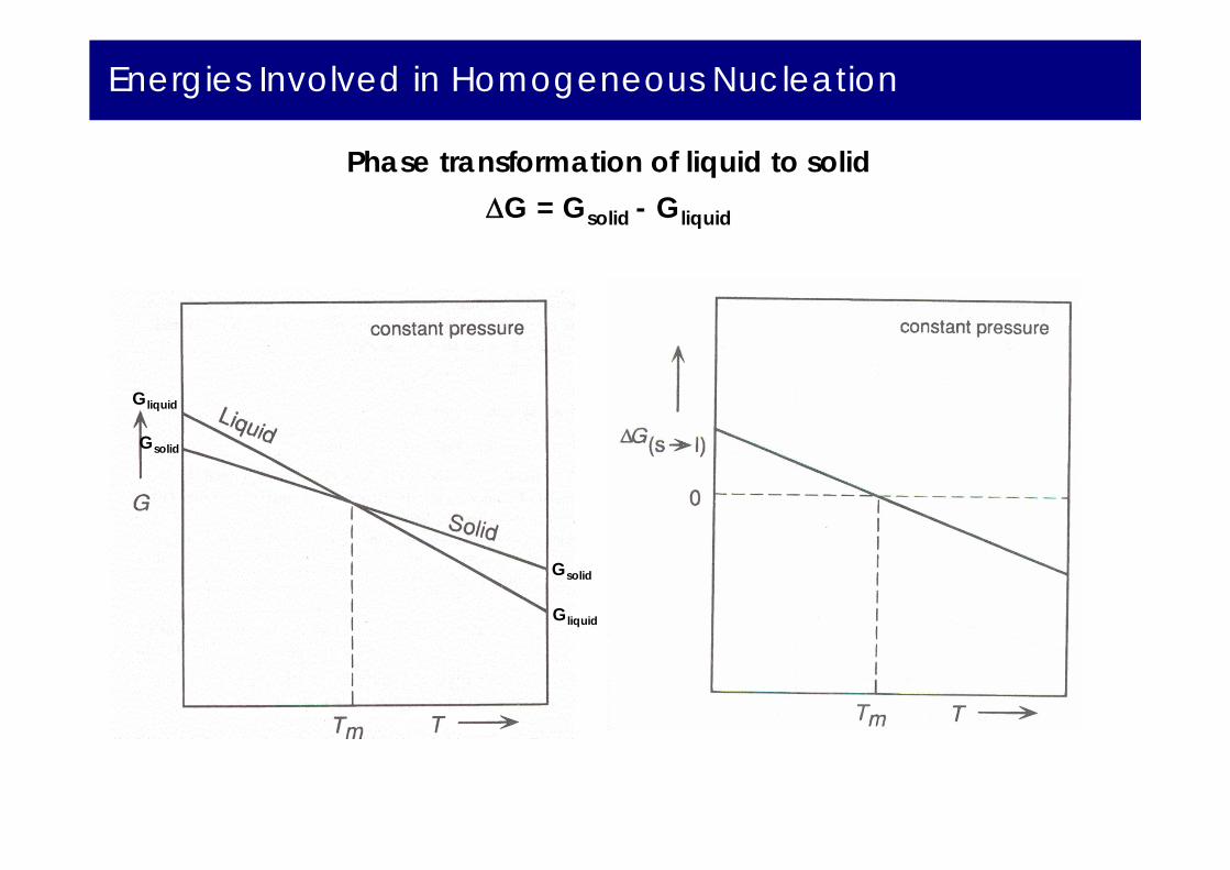
Energies Involved in Homogeneous Nucleation
Gliquid
Gliquid
Gsolid
Gsolid
Phase transformation of liquid to solidG = Gsolid - Gliquid
Energies Involved in Homogeneous Nucleation
Energies Involved in Homogeneous Nucleation
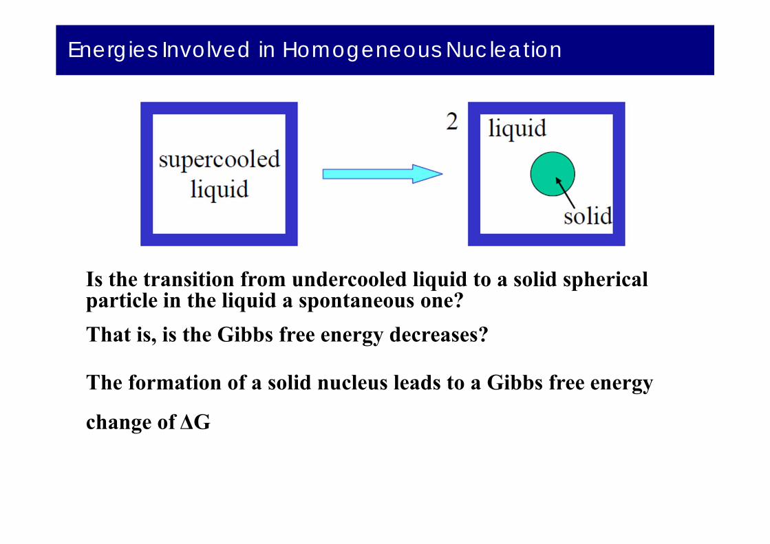
Is the transition from undercooled liquid to a solid spherical particle in the liquid a spontaneous one?That is, is the Gibbs free energy decreases?
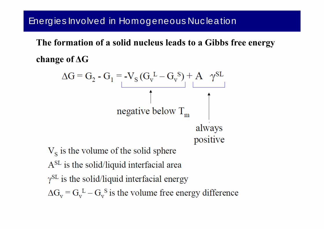
The formation of a solid nucleus leads to a Gibbs free energy
change of ΔG
Energies Involved in Homogeneous Nucleation
The formation of a solid nucleus leads to a Gibbs free energy
change of ΔG

Energies Involved in Homogeneous Nucleation
(1)Volume free energy
(2) Surface energy
Energies involved in homogenous nucleation
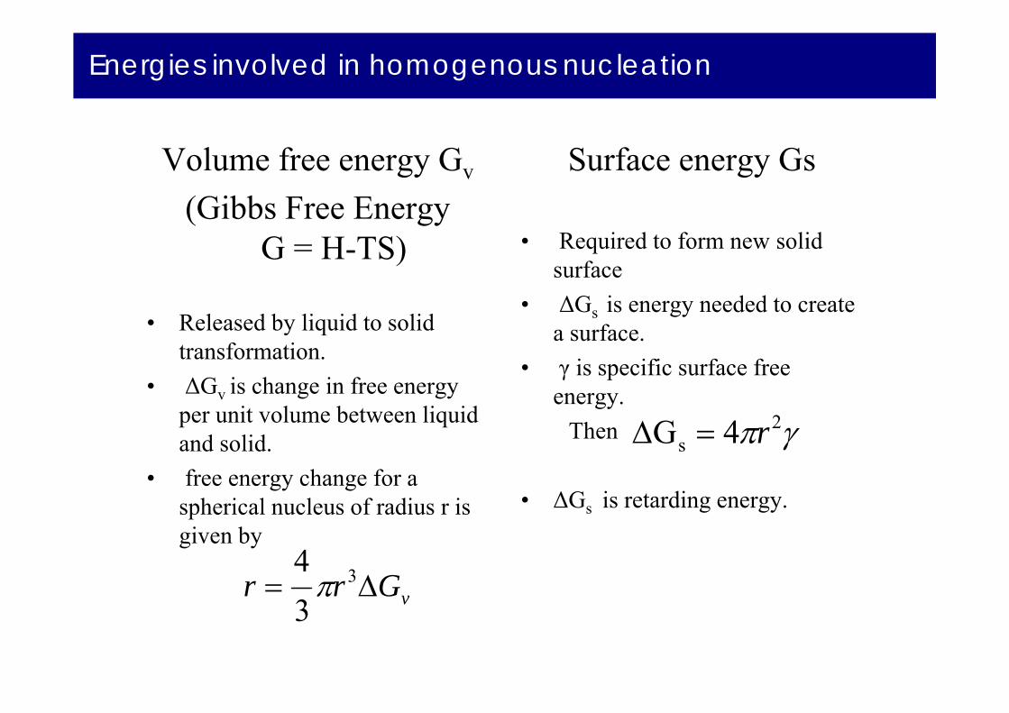
Volume free energy Gv
(Gibbs Free Energy G = H-TS)
• Released by liquid to solid transformation.
• ΔGv is change in free energy per unit volume between liquid and solid.
• free energy change for a spherical nucleus of radius r is given by
Surface energy Gs
• Required to form new solid surface
• ΔGs is energy needed to create a surface.
• γ is specific surface free energy.
Then
• ΔGs is retarding energy.
2s 4G r
vGrr 3
34

Energies involved in homogenous nucleation
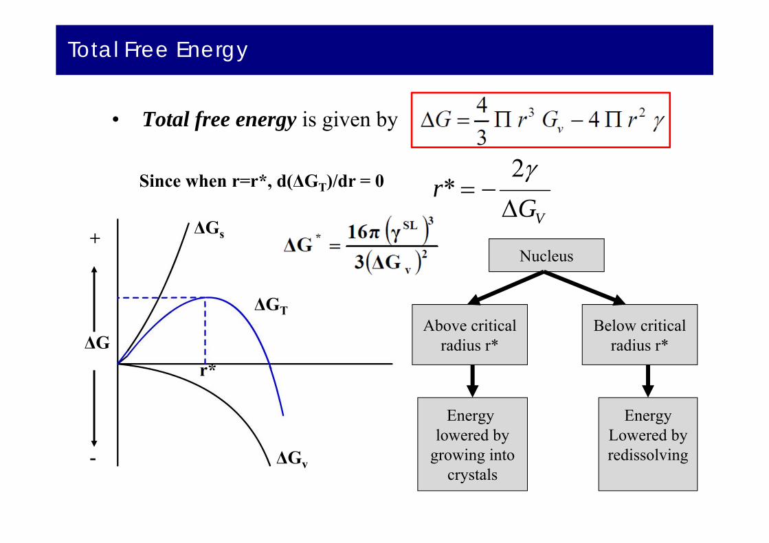
Total Free Energy
• Total free energy is given by
Nucleus
Above criticalradius r*
Below criticalradius r*
Energy lowered by
growing intocrystals
EnergyLowered byredissolving
VGr
2*Since when r=r*, d(ΔGT)/dr = 0
r*r
ΔG
+
- ΔGv
ΔGs
ΔGT
r*

Critical Radius Versus Undercooling
• Greater the degree of undercooling, greater the change in volume free energy ΔGv
• ΔGs does not change significantly.• As the amount of undercooling ΔT increases, critical
nucleus size decreases.• Critical radius is related to undercooling by relation
THT
rf
m
2*
r* = critical radius of nucleusγ = Surface free energyΔHf = Latent heat of fusionΔ T = Amount of undercooling.
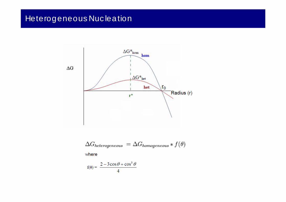
Both r* and G* decrease with increasing undercooling.

Critical Radius Versus Undercooling

Heterogeneous Nucleation
Heterogeneous nucleation occurs much more often than homogeneous
nucleation. Heterogeneous nucleation applies to the phase transformation
between any two phases of gas, liquid, or solid, typically for example,
condensation of gas/vapor, solidification from liquid, bubble formation from
liquid, etc.
Heterogeneous nucleation forms at preferential sites such as phase
boundaries, surfaces (of container, bottles, etc.) or impurities like dust. At
such preferential sites, the effective surface energy is lower, thus diminishes
the free energy barrier and facilitating nucleation.

Heterogeneous Nucleation
Heterogeneous nucleation can be considered as a surface catalyzed or
assisted nucleation process. The extent of how a surface can catalyze or
facilitate the nucleation depends on the contact angle of the nucleus with
respect to the substrate. The smaller the angle (or the stronger the wetting of
the surface), the lower the free energy change, and the lower the nucleation
barrier will be.

Heterogeneous Nucleation
Critical radius of the nucleus (r*) for a heterogeneous nucleation is the same
as that for a homogeneous nucleation, whereas the critical volume of the
nucleus (like the droplet for liquid nucleated from gas/vapor phase) is usually
smaller for heterogeneous nucleation than for homogeneous nucleation, due
to the surface wetting (spreading).

Homogeneous nucleation : Total Free Energy
• Total free energy is given by
Nucleus
Above criticalradius r*
Below criticalradius r*
Energy lowered by
growing intocrystals
EnergyLowered byredissolving
VGr
2*Since when r=r*, d(ΔGT)/dr = 0
r*r
ΔG
+
- ΔGv
ΔGs
ΔGT
r*
Heterogeneous Nucleation

Heterogeneous Nucleation
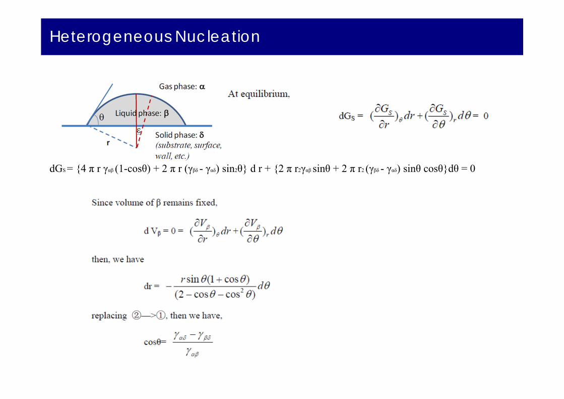
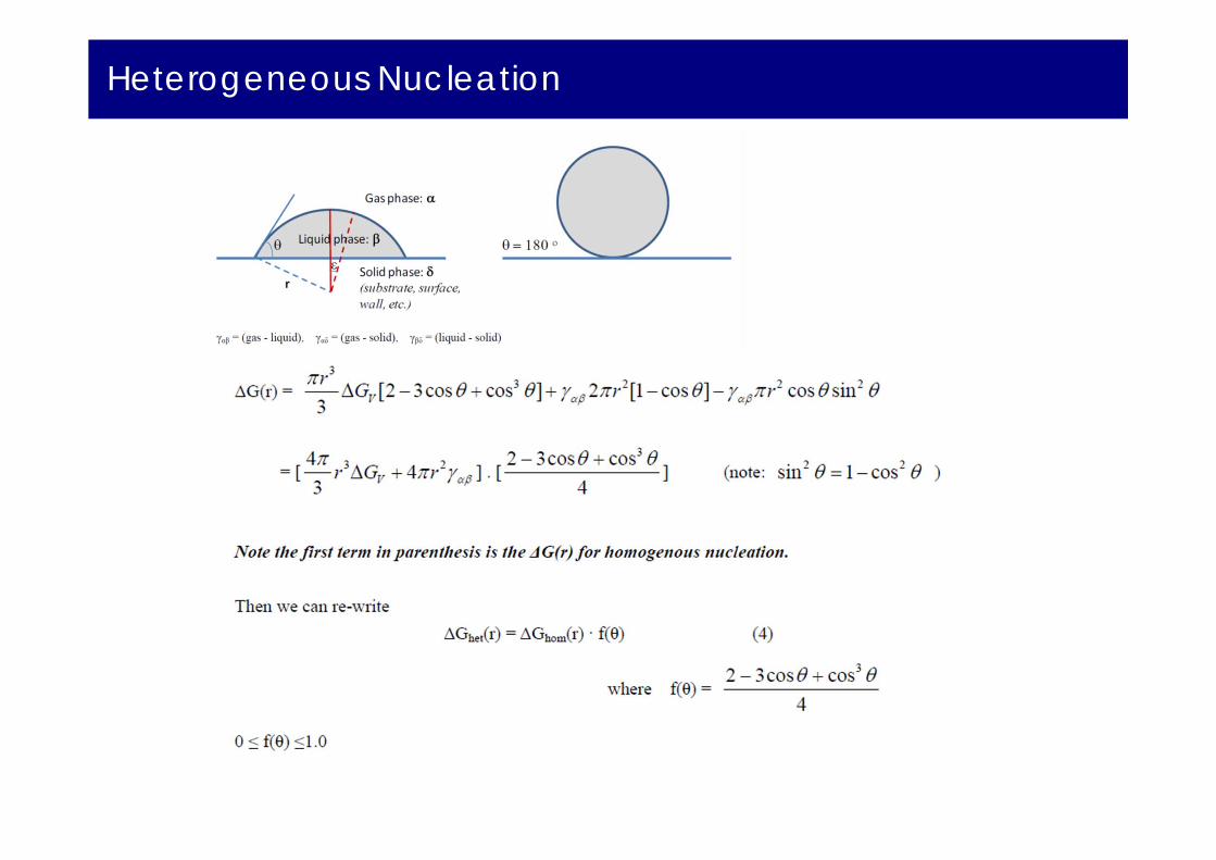
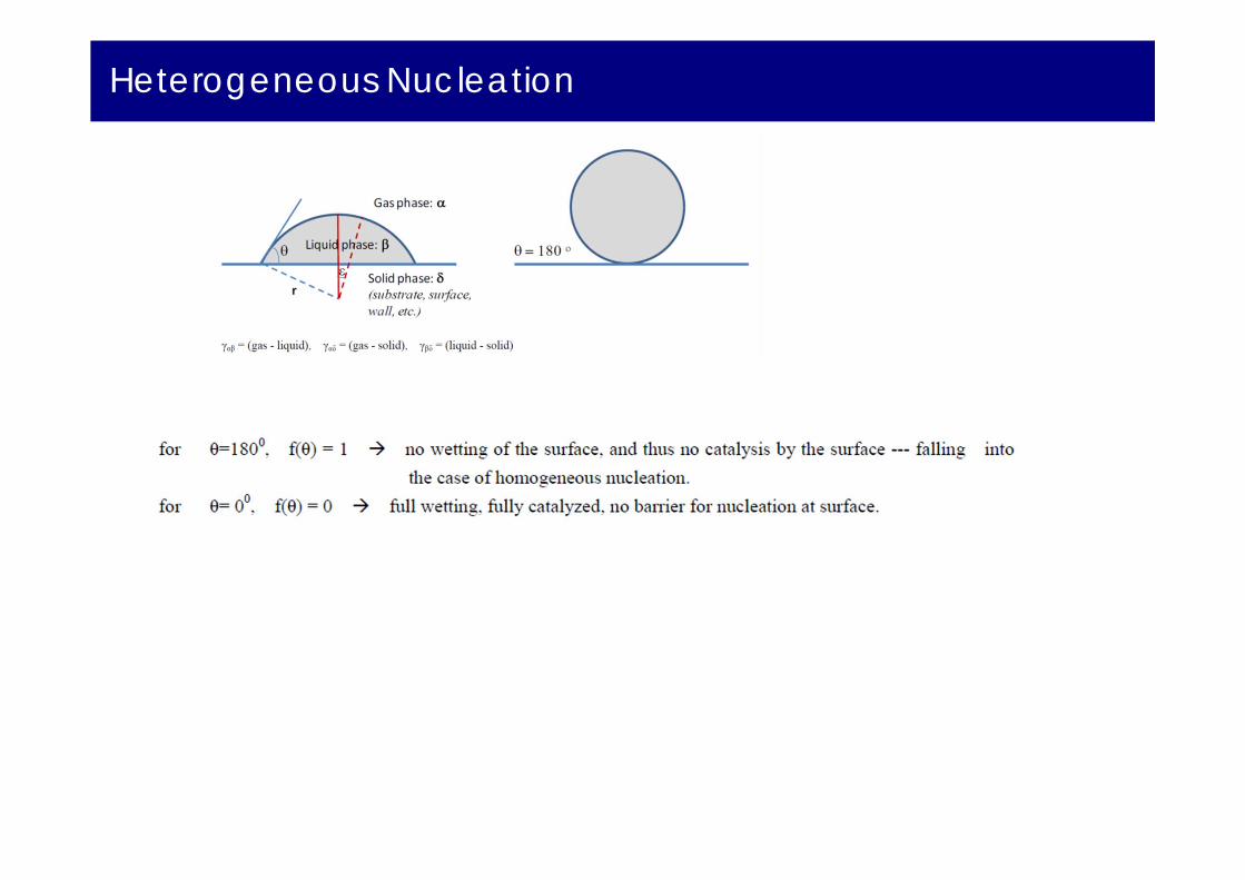
γαβ= (gas - liquid), γαδ= (gas - solid), γβδ= (liquid - solid)
Consider a droplet of liquid on a flat surface with fixed volume. The total surface
energy of the system is a function of the shape of the droplet.
The diagram above shows two different shapes of the same volume, but of
different surface area leading to different Surface energy:
Gs = γαβAαβ+ γαδAαδ+ γβδAβδ
where Aαβ, Aαδand Aβδare areas of αβ, αδ and βδ interfaces, respectively

Heterogeneous Nucleation
Gs = γαβAαβ+ γαδAαδ+ γβδAβδ
where Aαβ, Aαδand Aβδare areas of αβ, αδ and βδ interfaces, respectively
Assume r be the radius of curvature of the droplet, then:Aβδ= π r2 sin2θAαδ= A0 - π r2 sin2θ; A0 is the area of αδ interface without β
Thus,
Heterogeneous Nucleation
dGS = {4 π r γαβ (1-cosθ) + 2 π r (γβδ - γαδ) sin2θ} d r + {2 π r2γαβ sinθ + 2 π r2 (γβδ - γαδ) sinθ cosθ}dθ = 0

Heterogeneous Nucleation
Heterogeneous Nucleation
Heterogeneous Nucleation

Heterogeneous Nucleation

Heterogeneous Nucleation

Heterogeneous Nucleation
The cloud : Lots of small spherical water droplets too light to fall under gravity
The droplets need to freeze to ice which becomes a nucleus capable of attracting water vapor.
In cold days it snows and In hot days it rains.
The ice : The homogeneous nucleation temperature is –40 C (way too cold)
The solution : Heterogeneous nucleation
Air Pollution will provide the seeds (OK, not the best solution)Use silver iodide crystals decreases the nucleation T from-40 C to –4 C.
Heterogeneous Nucleation
Carbonate drinks have carbon dioxide which is dissolved under pressure.
When the can is opened the pressure drops and the gas comes out of solution in the form of bubbles.
Aluminum and glass are poor catalysts for heterogeneous nucleation.

Growth of Crystals and Formation of Grain Structure
• Nucleus grow into crystals in different orientations.• Crystal boundaries are formed when crystals join together
at complete solidification. • Crystals in solidified metals are called grains.• Grains are separated by grain boundaries.• More the number of nucleation sites available,
more the number of grains formed.

Types of Grains
• Equiaxed Grains: Crystals, smaller in size, grow equally in all directions. Formed at the sites of high concentration of the nuclie. Example:- Cold mold wall
• Columnar Grains: Long thin and coarse. Grow predominantly in one direction. Formed at the sites of slow cooling
and steep temperature gradient. Example:- Grains that are away from
the mold wall.Columnar Grains
Equiaxed Grains
Mold

Types of Grains

Casting in Industries
• In industries, molten metal is cast into either semi finished or finished parts.
Direct-Chill semicontinuousCasting unit for aluminum
Continuous castingof steel ingots
Grain Structure in Industrial castings
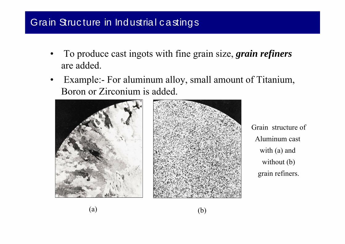
• To produce cast ingots with fine grain size, grain refiners are added.
• Example:- For aluminum alloy, small amount of Titanium, Boron or Zirconium is added.
(a) (b)
Grain structure ofAluminum cast
with (a) and without (b)
grain refiners.
Solidification of Single Crystal
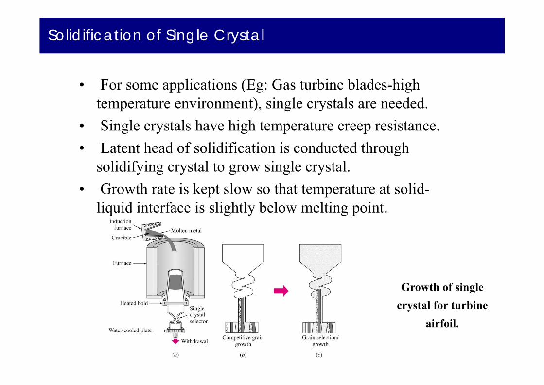
• For some applications (Eg: Gas turbine blades-high temperature environment), single crystals are needed.
• Single crystals have high temperature creep resistance. • Latent head of solidification is conducted through
solidifying crystal to grow single crystal.• Growth rate is kept slow so that temperature at solid-
liquid interface is slightly below melting point.
Growth of singlecrystal for turbine
airfoil.
Czochralski Process
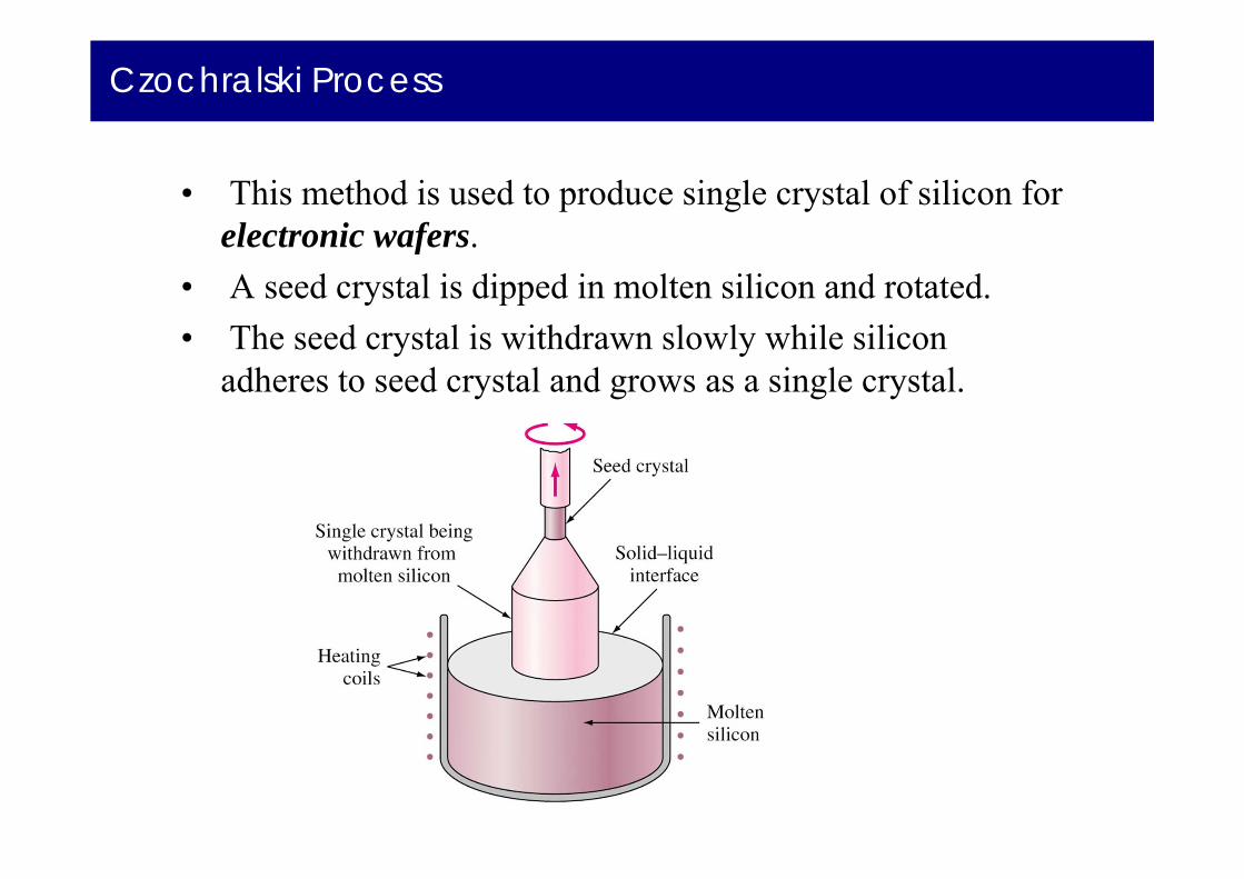
• This method is used to produce single crystal of silicon for electronic wafers.
• A seed crystal is dipped in molten silicon and rotated.• The seed crystal is withdrawn slowly while silicon
adheres to seed crystal and grows as a single crystal.

Metallic Solid Solutions
• Alloys are used in most engineering applications.• Alloy is an mixture of two or more metals and nonmetals.• Example:
Cartridge brass is binary alloy of 70% Cu and 30% Zinc. Iconel is a nickel based superalloy with about 10 elements.
• Solid solution is a simple type of alloy in which elements are dispersed in a single phase.
Substitutional Solid Solution
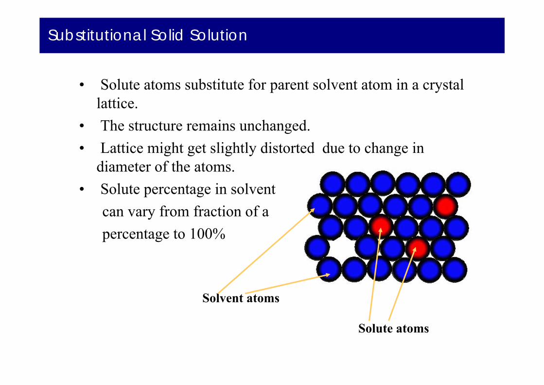
• Solute atoms substitute for parent solvent atom in a crystal lattice.
• The structure remains unchanged.• Lattice might get slightly distorted due to change in
diameter of the atoms. • Solute percentage in solvent
can vary from fraction of a percentage to 100%
Solvent atoms
Solute atoms
Substitutional Solid Solution
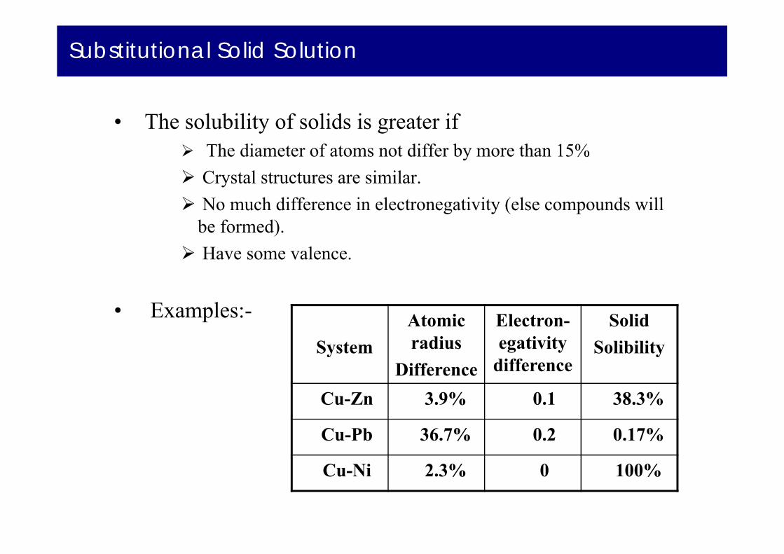
• The solubility of solids is greater if The diameter of atoms not differ by more than 15% Crystal structures are similar. No much difference in electronegativity (else compounds will
be formed). Have some valence.
• Examples:-System
Atomic radius
Difference
Electron-egativity
difference
SolidSolibility
Cu-Zn 3.9% 0.1 38.3%
Cu-Pb 36.7% 0.2 0.17%
Cu-Ni 2.3% 0 100%

Interstitial Solid Solution
• Solute atoms fit in between the voids (interstices) of solvent atoms.
• Solvent atoms in this case should be much larger than solute atoms.
• Example:- between 912 and 13940C, interstitial solid solution of carbon in γ iron (FCC) is formed.
• A maximum of 2.8% of carbon can dissolve interstitially in iron.
Carbon atoms r=0.075nm
Iron atoms r00.129nm

Crystalline Imperfections
• No crystal is perfect.• Imperfections affect mechanical properties,
chemical properties and electrical properties. • Imperfections can be classified as
Zero dimension point deffects. One dimension / line deffects (dislocations). Two dimension deffects. Three dimension deffects (cracks).

Point Defects – Vacancy
• Vacancy is formed due to a missing atom.• Vacancy is formed (one in 10000 atoms) during
crystallization or mobility of atoms. • Energy of formation is 1 ev.• Mobility of vacancy results in cluster of
vacancies.• Also caused due
to plastic defor--mation, rapid cooling or particlebombardment.
Vacancies moving to form vacancy cluster

Point Defects - Interstitially
• Atom in a crystal, sometimes, occupies interstitial site.
• This does not occur naturally.• Can be induced by irradiation.• This defects caused structural distortion.
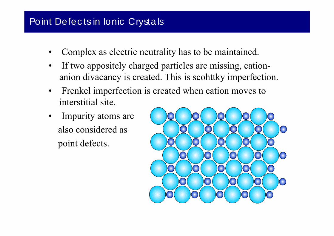
Point Defects in Ionic Crystals
• Complex as electric neutrality has to be maintained.• If two appositely charged particles are missing, cation-
anion divacancy is created. This is scohttky imperfection. • Frenkel imperfection is created when cation moves to
interstitial site. • Impurity atoms are
also considered as point defects.
Line Defects – (Dislocations)
• Lattice distortions are centered around a line. • Formed during
Solidification Permanent Deformation Vacancy condensation
• Different types of line defects are Edge dislocation Screw dislocation Mixed dislocation

Edge Dislocation
• Created by insertion of extra half planes of atoms.
• Positive edge dislocation
• Negative edge dislocation
• Burgers vectorShows displa-cement of atoms (slip).
Burgers vector

Screw Dislocation
• Created due to shear stresses applied to regions of a perfect crystal separated by cutting plane.
• Distortion of lattice in form of a spiral ramp.• Burgers vector is parallel to dislocation line.

Mixed Dislocation
• Most crystal have componentsof both edge and screw dislocation.
• Dislocation, since have irregular atomic arrangementwill appear as dark lineswhen observed in electronmicroscope.
Dislocation structure of iron deformed14% at –1950C

Grain Boundaries
• Grain boundaries, twins, low/high angle boundaries, twists and stacking faults
• Free surface is also a defect : Bonded to atoms on only one side and hence has higher state of energy Highly reactive
• Nanomaterials have small clusters of atoms and hence are highly reactive.
65

Grain Boundaries
66
• Grain boundaries separate grains.• Formed due to simultaneously growing crystals meeting
each other.• Width = 2-5 atomic diameters. • Some atoms in grain boundaries have higher energy. • Restrict plastic flow and prevent dislocation movement.
3D view ofgrains
Grain BoundariesIn 1018 steel

Twin Boundaries
• Twin: A region in which mirror image pf structure exists across a boundary.
• Formed during plastic deformation and recrystallization.
• Strengthens the metal.
Twin
Twin Plane
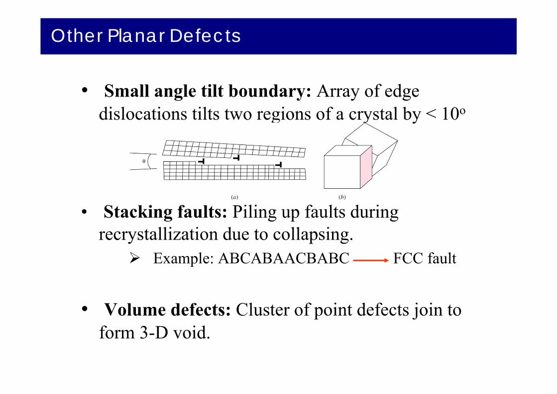
Other Planar Defects
• Small angle tilt boundary: Array of edge dislocations tilts two regions of a crystal by < 10o
• Stacking faults: Piling up faults during recrystallization due to collapsing.
Example: ABCABAACBABC FCC fault
• Volume defects: Cluster of point defects join to form 3-D void.

Observing Grain Boundaries - Metallography
• To observe grain boundaries, the metal sample must be first mounted for easy handling
• Then the sample should be ground and polished with different grades of abrasive paper and abrasive solution.
• The surface is then etched chemically.
• Tiny groves are producedat grain boundaries.
• Groves do not intensely reflect light. Hence observed by opticalmicroscope.
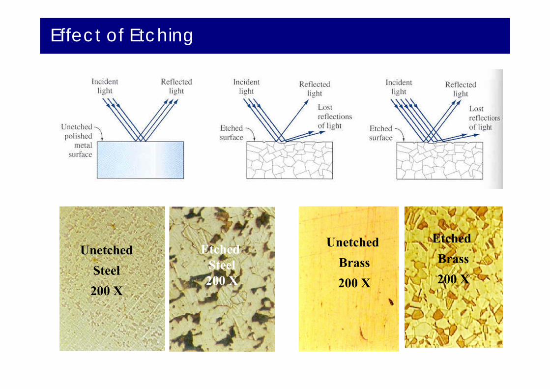
Effect of Etching
Unetched Steel200 X
Etched Steel200 X
Unetched Brass200 X
Etched Brass200 X

Grain Size
• Affects the mechanical properties of the material
• The smaller the grain size, more are the grain boundaries.
• More grain boundaries means higher resistance to slip (plastic deformation occurs due to slip).
• More grains means more uniform the mechanical properties are.
Measuring Grain Size
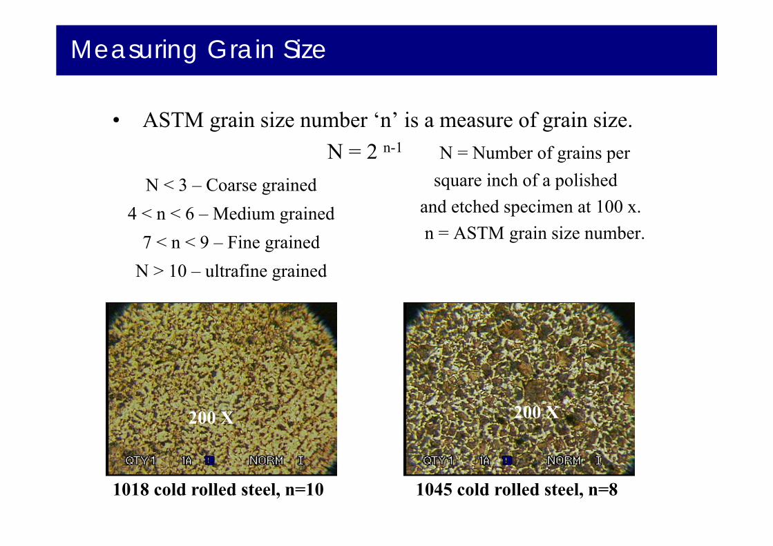
• ASTM grain size number ‘n’ is a measure of grain size.N = 2 n-1 N = Number of grains per
square inch of a polishedand etched specimen at 100 x.n = ASTM grain size number.
200 X 200 X
1018 cold rolled steel, n=10 1045 cold rolled steel, n=8
N < 3 – Coarse grained4 < n < 6 – Medium grained
7 < n < 9 – Fine grainedN > 10 – ultrafine grained
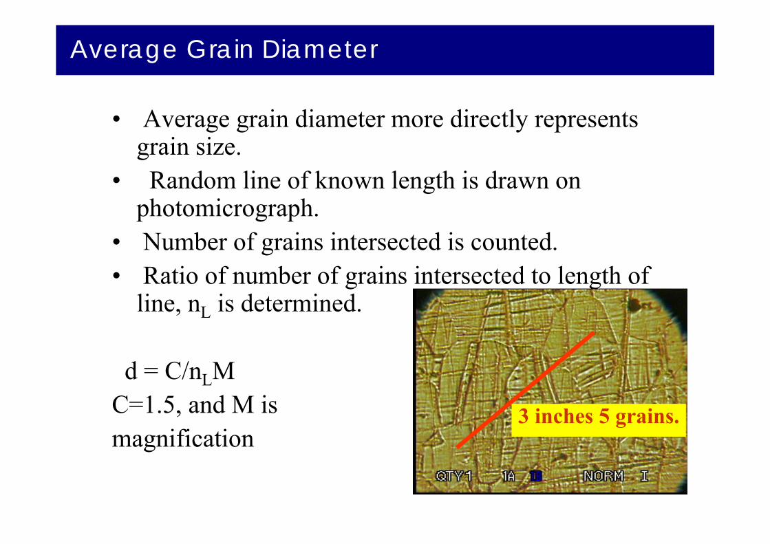
Average Grain Diameter
• Average grain diameter more directly represents grain size.
• Random line of known length is drawn on photomicrograph.
• Number of grains intersected is counted.• Ratio of number of grains intersected to length of
line, nL is determined.
d = C/nLM C=1.5, and M is magnification
3 inches 5 grains.

Transmission Electron Microscope
• Electron produced by heated tungsten filament.
• Accelerated by high voltage (75 - 120 KV)
• Electron beam passes through very thin specimen.
• Difference in atomic arrangement change directions of electrons.
• Beam is enlarged and focused on fluorescent screen.
Collagen Fibrilsof ligament asseen in TEM
Transmission Electron Microscope
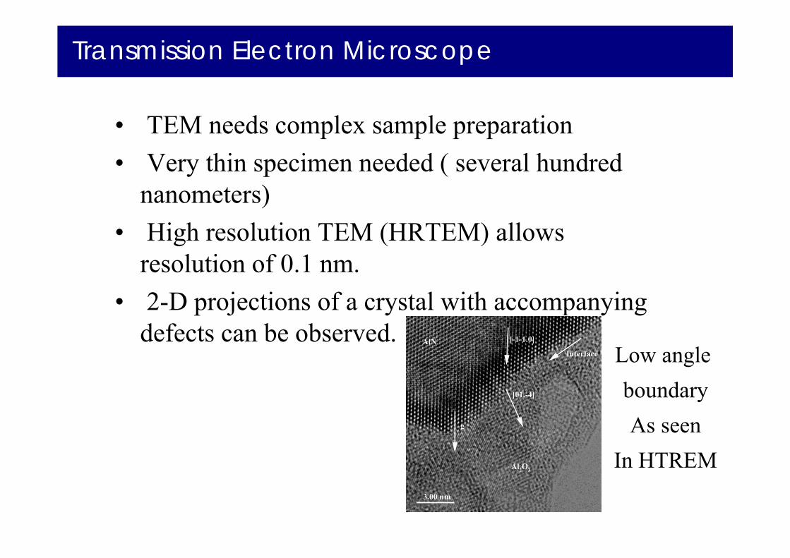
• TEM needs complex sample preparation• Very thin specimen needed ( several hundred
nanometers)• High resolution TEM (HRTEM) allows
resolution of 0.1 nm.• 2-D projections of a crystal with accompanying
defects can be observed. Low angle boundaryAs seen
In HTREM

Scanning Electron Microscope
• Electron source generates electrons.
• Electrons hit the surface and secondary electrons are produced.
• The secondary electrons are collected to produce the signal.
• The signal is used to produce the image.
TEM of fractured metal end