forwell qdc catalog - stamtec
TRANSCRIPT
Stamtec has been providing dependable, a�ordably priced metal stamping presses for almost 40 years in North America, and almost 70 years worldwide through our parent company Chin Fong. Our 72,000 sq. ft. sales, service, logistics, and assembly facility in Tennessee is home not only to North America's largest inventory of new presses and spare parts, but also our most important asset - our people. Our sta� of engineering, sales, service, and support personnel are here to serve you in the most timely and professional manner. So, tap into our global strength, and grow with us as we grow with you!
METAL STAMPING & FORMING EQUIPMENT
FORGING PRESSESWARM / HOT AND COLD
SERVO PRESSES1-POINT AND 2-POINT
GAP AND STRAIGHT SIDE
STRAIGHT SIDE PRESSES1-POINT, 2-POINT AND 4-POINT
GAP FRAME PRESSES1-POINT AND 2-POINT
U.S.A. - STAMTEC, INC.
4160 Hillsboro Highway
Manchester, TN 37355 U.S.A.
TEL: +1-931-393-5050
FAX: +1-931-393-5060
www.stamtec.com
METAL STAMPING & FORMING EQUIPMENT
COIL FEEDING & HANDLING SYSTEMS
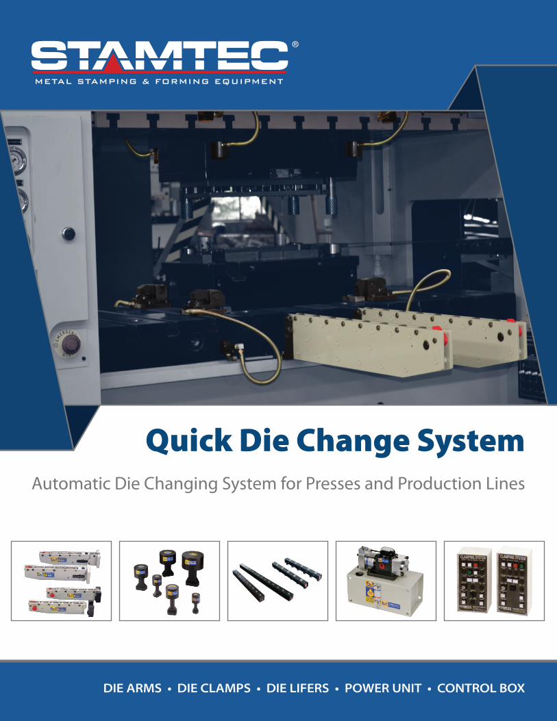
Quick Die Change SystemAutomatic Die Changing System for Presses and Production Lines
METAL STAMPING & FORMING EQUIPMENT
DIE ARMS • DIE CLAMPS • DIE LIFERS • POWER UNIT • CONTROL BOX

DIE ARMS • DIE CLAMPS • DIE LIFERSPOWER UNIT • CONTROL BOX
DIE ARMS • DIE CLAMPS • DIE LIFERSPOWER UNIT • CONTROL BOX
2 31
NotesQuick Die Change SystemAutomatic Die Changing System for Presses and Production Lines
Die Arm SeriesDie Lifter Series Power UnitDie Clamp Series Die Arm Series
STAMTEC Quick Die Change (Q. D. C.) systems automate the die changing process and provide increased speed, e�ciency and productivity. Q.D.C. systems not only reduce die change time, but promote diverse small batch production runs and streamline production management.
FEATURES• Decreased die change time• Designed for hydraulic and pneumatic presses• Increased efficiency• Reduced labor costs• Safer operations
Quick Die Change systems are becoming a standard for large manufacturers looking to increase production e�ciency, and improve overall working environments. Automated operations reduce labor expenses, but also reduce workshop accidents and the physical stresses on operators, making them more productive.
Date:
METAL STAMPING & FORMING EQUIPMENT METAL STAMPING & FORMING EQUIPMENT

DIE ARMS • DIE CLAMPS • DIE LIFERSPOWER UNIT • CONTROL BOX
DIE ARMS • DIE CLAMPS • DIE LIFERSPOWER UNIT • CONTROL BOX
30 3
Automating the die changing process and providing increased speed, e�ciency and productivity.
• Die Arms • Die Clamps • Die Lifters • Power Unit • Control Box
Die Clamp Series Die Arm SeriesHMI ControlDie Lifter Series Power Unit
In addition, all dies can be changed without any modi�cation allowing for the use of standardized die and press equipment, SAVING COSTS.
Lastly, multiple presses can share a single Q. D. C. system, further economizing on costs and resulting in higher e�ciency and productivity.
Model on P12~P13
Example Die Cart Systems
Simultaneous 2-die change using two carts. The shortestdie change time is achieved.
Die change using a moving bolster and two stationary tables. Low cost type.
Die change using a powered2-die cart. Many applicationsare possible.
Cart
Press
Cart
Cart
Press
Cart Cart
Cart
Press PressA A B B
A A
A
B
Fixed Platform
Press Press
BA
Press
A
A B
BA
Press
PressA
B
Cart
Press
Cart
BA
Press
Cart Cart
BA
PressB
A
Air Pump AV Air Control Valve Rotary Unit
At Air 5kg/cm² PressureRatio
06 1:84
1:60
1:50
1:40
1:30
1:20
1:16
1:10
1:8
1:5
420 (kg/cm²)
300 (kg/cm²)
250 (kg/cm²)
200 (kg/cm²)
150 (kg/cm²)
100 (kg/cm²)
80 (kg/cm²)
50 (kg/cm²)
40 (kg/cm²)
26 (kg/cm²)
07
08
09
10
12
14
16
20
24
1/4"PT x 1/4"HPressure Resistance : 700kg/cm 2
1/4"PT
1/4"Hose
Related Products for Press Machines
METAL STAMPING & FORMING EQUIPMENT METAL STAMPING & FORMING EQUIPMENT

DIE ARMS • DIE CLAMPS • DIE LIFERSPOWER UNIT • CONTROL BOX
DIE ARMS • DIE CLAMPS • DIE LIFERSPOWER UNIT • CONTROL BOX
4 29
E�ects of introducing QDCSBefore and After
STAMTEC Quick Die Change System from Forwell is an automatic die changing system that can be speci�cally designed for hydraulic and mechanical power presses and press production lines. This system automates the die changing process and provides increased speed, e�ciency and productivity to a workshop. The Quick Die Change System not only reduces die change time, but also promotes diverse small batch production runs and streamlines production management.
BEFORE
Manual operation. Automation
Die / mold changing takes a long time and manpower to tighten.
Only touch the buttons on the control panel.
Clamping force will be di�erent byeach operators.
The clamping force is the same.Increased safety.
Operator time can be wasted, with an increasedrisk of injury.
Control panel operation saves timeand reduces the risk of injury.
No alarm noti�cation while loosening the screws. Alarm device will stop the machineimmediately.
AFTER
Besides die change systems Forwell o�ers a wide range of hydraulic and pneumatic controlled components and equipment for plastic injection molds and workpiece clamping systems for machine tools. The components shown below represent just a selection of what we have available. For related brochures and further details, don't hesitate to contact us.
RC / RD / RE / RF Die ArmDetachable, Drop-down and Folding Series
Model
Air Supply
Power Ratio
Power Pressure
Area of Air Outlet
2.5~5.5 kg/cm 2
175~385 kgf/cm 2
Air Pressure x 70
0.42 cm2
OL107
106.
5
Air Outlet
M10 Screw-4 Hole
Ø30x2.5
3.8 96 77 52 1.5
Ø16.5
Ø20x2
Ø12
2626
10
14.5 414-Ø11
Ø22
70 70
226.5
METAL STAMPING & FORMING EQUIPMENT METAL STAMPING & FORMING EQUIPMENT

DIE ARMS • DIE CLAMPS • DIE LIFERSPOWER UNIT • CONTROL BOX
DIE ARMS • DIE CLAMPS • DIE LIFERSPOWER UNIT • CONTROL BOX
28 5
RE / RF Bolster Extension SeriesFolding RE / RF Series
2040
H
12 23
2
8
L
A = ( L+50 )
8
H 2040
12
L
A = ( L+50 )
2
C
RFRE
55
Y
X
55
B
H
45
China Patent No: ZL 01 2 64184.7
RE.RF-500-800
RE.RF-500-1250
RE.RF-700-600
RE.RF-800-1600
RE.RF-500-1600
RE.RF-900-1600
500
500
700
800
500
900
800
1250
600
1600
1600
1600
550
550
750
850
550
950
115
525
525
725
RE.RF-700-1600 700 1600 750 725
825
525
925
5
7
5
8
9
A
A
B
B90 150
120
160
120
7200
200
RE.RF-800-800 800 800 850 825 8160
200
Folding RE/RF Series
B C HModel Die Travel (L) Max. Load
(kg)Overall
Length (A)
FixtureRollers Installed
Dimensions
Drop Down
X Y
No. of Circuits Circuit Code System Configuration
One circuit for clamping the upper die
One circuit for clamping the lower die
One circuit for simultaneously clamping the upper and lower dies
One circuit for the lifter
One circuit for upper dieOne circuit for lower die
One circuit for simultaneously clamping the upper and lower diesOne circuit for the lifter
Two circuits for clamping the upper and lower diesOne circuit for the lifter
Two circuits for clamping the upper dieOne circuit for clamping the lower dieOne circuit for the lifter
The above list is planned according to the number of circuts and value plan based on usage.In between circuit type “C” means ON at all times. Circuit type “D” means OFF at all times.
Selection of system componentsCompact, space-saving, wide range of applications
The Forwell Quick Die Change System boosts the e�ciency and safety of small to large scale pressing operations. For the system con�guration best suited to your needs, please refer to the following sections.
- -1 CFP 6308UØ 63Ø 100
FP 63 08U
C: Die Clamp | D: Die Lifter
Surface area of pressure increased rod
Surface area of piston
METAL STAMPING & FORMING EQUIPMENT METAL STAMPING & FORMING EQUIPMENT

Selection of clampsDie Clamps for secure clamping, quick mold changing and safe operation
DIE ARMS • DIE CLAMPS • DIE LIFERSPOWER UNIT • CONTROL BOX
DIE ARMS • DIE CLAMPS • DIE LIFERSPOWER UNIT • CONTROL BOX
6 27
Basic Clamp Selection
Select TX Clamp when die U-slots are provided.
Select TY Clamp when die U-slots are not provided.
Determine the required clamping force.
Clamping force = 20% of Press Tonnage.
Distribution of upper to lower die clamping force.
Higher press tonnage for the upper die.
Ratio of upper clamping force to lower clamping force=3:2
(Single die clamping force)=(upper or lower die clamping force)÷number of clamps
How to determine the number of clamps required.
Determine the number of clamps according to the dimensions and con�guration of your die and the T-slot arrangement on the press.
Screw Bolt M16 M18 M20 M24 M30 M38
Clamping Force 3 4 5 10 15 20
Determine the number of clamps according to the dimensions and con�guration of your die and the T-slot arrangement on the press.
Die Clamp Series
RD Bolster Extension SeriesDrop-Down RD Series
24 75
C
Fixture
L
A
X
Y
2 8
9570
H
B
45
RD-500-800 500
RD-500-1250 500
RD-500-1600 500
RD-700-600 700
RD-800-800 800
RD-800-2000 800
RD-900-1600 900
RD-1000-1600 1000
800
1250
1600
600
800
2000
1600
1600
550
550
550
750
RD-700-1000 700 1000 750
850
RD-800-1600 800 1600 850
850
950
1050
115 52
120
160
200
120
160
160
200
200
200
5
7
8
9
9
10
A
B
A
B
B
C
140
180
220
140
180
220
220
620
660
700
820
180 860
960
220 1000
1000
1100
1200
Drop-Down RD Series
B C HModel Die Travel (L) Max. Load
(kg)Overall
Length (A)
FixtureRollers Installed
Dimensions
Drop Down
X Y
METAL STAMPING & FORMING EQUIPMENT METAL STAMPING & FORMING EQUIPMENT
DIE ARMS • DIE CLAMPS • DIE LIFERSPOWER UNIT • CONTROL BOX
DIE ARMS • DIE CLAMPS • DIE LIFERSPOWER UNIT • CONTROL BOX
26 7
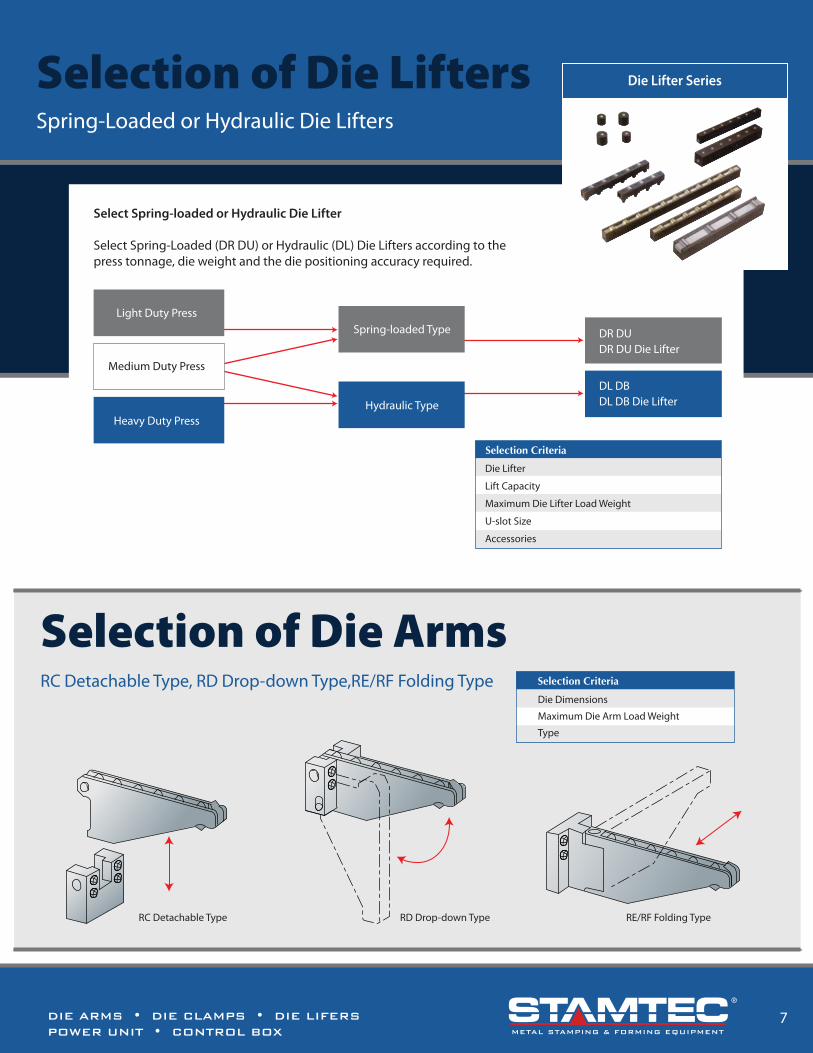
Selection of Die LiftersSpring-Loaded or Hydraulic Die Lifters
DL DBDL DB Die Lifter
DR DUDR DU Die Lifter
Select Spring-loaded or Hydraulic Die Lifter
Select Spring-Loaded (DR DU) or Hydraulic (DL) Die Lifters according to thepress tonnage, die weight and the die positioning accuracy required.
Light Duty PressSpring-loaded Type
Hydraulic Type
Medium Duty Press
Heavy Duty Press
Die Lifter
Lift Capacity
Maximum Die Lifter Load Weight
U-slot Size
Accessories
Selection Criteria
Die Lifter Series
Selection of Die ArmsRC Detachable Type, RD Drop-down Type,RE/RF Folding Type
RC Detachable Type RD Drop-down Type RE/RF Folding Type
Die Dimensions
Maximum Die Arm Load Weight
Type
Selection Criteria
RC Bolster Extension SeriesHeavy-Duty
RC-1200-2500
RC-1300-2500
RC-1500-2500
RC-1600-2500
RC-1700-2500
1200
1300
1500
1600
1700
2500
2500
2500
2500
2500
1250
1350
1550
RC-1400-2500 1400 2500 1450
1650
1750
115 46
B C H
120
15
17
14
18
19
20
A RC-120
Model Die Travel (L) Max. Load(kg)
OverallLength (A)
Fixture Rollers InstalledDimensions
Fixture Model
Adjustable Support
Fixture
Dis
tanc
e fr
om b
olst
er to
gro
und
H
B
45
AL
2 8
Height adjustable ±80mm
23.5
6443.5
c
• Requires adjustable support if die travels over 1000mm. These models come standard with adjustable support.• Contact us for other speci�cations.
Detachable RC Series
METAL STAMPING & FORMING EQUIPMENT METAL STAMPING & FORMING EQUIPMENT

Selection of Power UnitTypical Hydraulic Schematics
DIE ARMS • DIE CLAMPS • DIE LIFERSPOWER UNIT • CONTROL BOX
DIE ARMS • DIE CLAMPS • DIE LIFERSPOWER UNIT • CONTROL BOX
8 25
• (SOL) (DC 24V, AC110V, AC220V)
When ordering, please con�rm the usage voltage of the magnetical valve.
NO
Normal Open
NC
Normal Closed
NC Circuit(Die Lifter)
NO Circuit(Clamps)
12
SOL ON Pressure Rise SOL OFF Pressure Rise
FP Pump
Combined Circuit Example)
E
D
S
NONC
1234
Filter
RC Bolster Extension SeriesLight and Medium-Duty
RC-500-800
RC-500-1250
RC-500-1600
RC-700-600
RC-700-1000
RC-800-800
RC-800-1600
RC-800-2000
RC-900-1600
RC-1000-1600
RC-120
RC-160
RC-200
RC-120
RC-200
RC-200
500
500
500
700
700
800
800
800
900
1000
800
1250
1600
600
1000
800
1600
2000
1600
1600
550
550
550
750
750
850
850
850
950
1050
120
160
200
120
160
160
200
200
200
115
465
7
8
9
9
10RC-200
RC-160
A
A
B
B
C
B
46
50
50
B C H
2-Ø10 20
80
98
1240
40206-M14x25
2-Ø10 20
80
98
1240
40206-M12x25
2-Ø10 20
80
98
1240
204-M12x25
Model/Length/Max. Load Mounting Hole Dimensions
B
45
H
24 75
70 95
L
A
2
C 15
43.5
8
RC Series
Model Die Travel (L) Max. Load(kg)
OverallLength (A)
Fixture Rollers InstalledDimensions
Fixture Model
METAL STAMPING & FORMING EQUIPMENT METAL STAMPING & FORMING EQUIPMENT

DIE ARMS • DIE CLAMPS • DIE LIFERSPOWER UNIT • CONTROL BOX
DIE ARMS • DIE CLAMPS • DIE LIFERSPOWER UNIT • CONTROL BOX
24 9
RC / RD / RE / RF Die ArmDetachable, Drop-down and Folding Series
The hydraulic pump ensures tight and stable die clamping and allows the system to maintain clamping pressure on the mold even when there is a power failure or air pressure drops. The PCB Fine Piercing System uses air-driven hydraulic pumps resulting in very high clamping pressures, high energy e�ciency and convenient automated operations. Forwell’s hydraulic pump units also feature an easy to adjust air pressure valve to e�ectively control the systems air pressure.
Hydraulic Power UnitsVery secure and stable clamping
At 5kg/cm2 Air Pressure
FP63 Pressure Ratio
06
07
08
09
10
12
14
16
20
24
420 (kg/cm2)
300 (kg/cm2)
250 (kg/cm2)
200 (kg/cm2)
150 (kg/cm2)
100 (kg/cm2)
80 (kg/cm2)
50 (kg/cm2)
40 (kg/cm2)
26 (kg/cm2)
1 : 84
1 : 60
1 : 50
1 : 40
1 : 30
1 : 20
1 : 16
1 : 10
1 : 8
1 : 5
FP 6308U-1-C FP 6308U-2-2C
FP 6308U-4-3CD FP 1014U-4-3CD
FP 6308U-3-2C
Die Arm makes it easy to move dies to an accessible area with a crane or forklift truck for convenient diechanges. Three di�erent designs are available: Detachable RC series, drop-down RD series (alternatemodel), and folding RE/RF series.
METAL STAMPING & FORMING EQUIPMENT METAL STAMPING & FORMING EQUIPMENT

Hydraulic Power UnitsFP63 and FP100 Pump Speci�cations
DIE ARMS • DIE CLAMPS • DIE LIFERSPOWER UNIT • CONTROL BOX
DIE ARMS • DIE CLAMPS • DIE LIFERSPOWER UNIT • CONTROL BOX
10 23
ModelTotal
Circuits
1
2
3
4
13.90 in. (353 mm)
13.90 in. (353 mm)
16.65 in. (423 mm)
19.41 in. (493 mm)
15.47 in. (393 mm)
15.47 in. (393 mm)
18.23 in. (463 mm)
20.98 in. (533 mm)
6
6
7.5
9
4.7
4.7
5.9
7.1
50.71 lbs. (23 kg)
59.53 lbs. (27 kg)
77.16 lbs. (35 kg)
94.80 lbs. (43 kg)
A BReservoirCapacity
AvailableLubricant Weight Lubricant
FP6308U
FP6308U
FP6308U
FP6308U
7.87 in. (200 mm)
3.15 in.(80 mm)
1.38 in.(35 mm)
1.38 in.(35 mm)
11.6
9 in
. (29
7 m
m)
13.9
8 in
. (35
5 m
m)
0.79 in.(20 mm)
0.79 in.(20 mm)8-Ø14
AB
1/4PTAir Inlet
1/4PT
Oil Outlet
1.38
in.
(35
mm
)1.
38 in
.(3
5 m
m) 3.
15 in
.(8
0 m
m)
ISO VG32- VG68
Standardhydraulic oil
Model : FP63 Pump
3/8PT
Air Inlet
1/4PTOil Outlet
A
B8-Ø14
10.04 in.(255 mm)
1.38
in.
(35
mm
)1.
38 in
.(3
5 m
m) 3.
15 in
.(8
0 m
m)
3.15 in.(80 mm)
1.38 in.(35 mm)
1.38 in.(35 mm)
0.79 in.(20 mm)
0.79 in.(20 mm)
11.6
9 in
. (29
7 m
m)
13.8
6 in
. (35
2 m
m)
ModelTotal
Circuits
1
2
3
4
13.90 in. (353 mm)
13.90 in. (353 mm)
16.65 in. (423 mm)
19.41 in. (493 mm)
15.47 in. (393 mm)
15.47 in. (393 mm)
18.23 in. (463 mm)
20.98 in. (533 mm)
6
6
7.5
9
3.8
3.8
4.8
5.8
66.14 lbs. (30 kg)
74.96 lbs. (34 kg)
92.59 lbs. (42 kg)
110.23 lbs. (50 kg)
A BReservoirCapacity
AvailableLubricant Weight Lubricant
FP1014U
FP1014U
FP1014U
FP1014U
ISO VG32- VG68
Standardhydraulic oil
Model : FP100 Pump
DB Die Lifter (Ball Type) DB-28 Speci�cations and Dimensions
DB-80-400
DB-80-500
DB-80-600
DB-80-700
DB-80-800
DB-80-900
DB-80-1000
DB-80-1100
DB-80-1200
DB-80-1300
DB-80-1400
DB-80-1500
DB-80-1600
DB-80-1700
400
500
600
700
800
900
1000
1100
1200
1300
1400
1500
1600
1700
4
6
7
9
10
11
13
14
15
16
18
19
20
22
3
3
4
4
6
6
6
8
8
8
10
10
10
12
80
90
80
90
80
90
80
90
100
90
100
90
100
90
120
200
80
90
80
90
80
90
100
90
100
90
100
90
80
90
160
220
80
90
80
90
100
90
100
90
100
90
80
90
200
240
80
90
100
90
100
90
100
90
80
90
80
90
240
260
280
90
100
90
100
90
80
90
80
90
100
280
DB-80 for Dies 1500kg or More
280
90
100
90
80
90
80
90
100
90
100
300
280
90
80
90
100
90
100
90
100
320
80
90
100
90
100
90
100
90
90
100
90
100
90
90
100
90 90 90
Lift Cylinder (kg)
pcs
4400
4400
6600
6600
8800
8800
11000
11000
11000
13200
13200
15400
15400
17600
Lift Force
Lift Cylinder Pitch (mm) Margin
P1 P2 P3 P4
BallQ'ty
P5 P6 P7 P8 P9 P10
90
100
90
100
90
P11
90
100
90
P12 P13 P14 P15
87.5
62.5
75
87.5
62.5
75
87.5
62.5
75
87.5
62.5
75
87.5
62.5
C
Model Overall(mm)
Normal Status LiftedU- Slot Dimensions
80 +0.5+0.25
80+0
.20
"U"
21
Cylinder60PnP2...P3....P4.....P14-M8*85L 60
M6 (Leveling Shim Provided)
Screw
4
Oil Inlet 1/8"PT
75-0 -0
.1
79 0.1L
L-2512.5 12.5
75 75 CC 75 75 75*n
32
Low
er T
han
Tabl
e 1
Floa
t on
Tabl
e 2
• For purchases please attach a bolster plate diagram for correct sizing of the waste material hole at the bottom.
METAL STAMPING & FORMING EQUIPMENT METAL STAMPING & FORMING EQUIPMENT

DB Die Lifter (Ball Type) DB-50 Speci�cations and Dimensions
DIE ARMS • DIE CLAMPS • DIE LIFERSPOWER UNIT • CONTROL BOX
22 11
Power UnitsFP63 Power Unit Speci�cations
0 1 2 3 4 5 6 7
Oil Volume Output (I/min) Oil Volume Output (I/min) Oil Volume Output (I/min)
Oil Volume Output (I/min) Oil Volume Output (I/min) Oil Volume Output (I/min)
Oil Volume Output (I/min) Oil Volume Output (I/min) Oil Volume Output (I/min)
FP-6309 0.9 I/min, Pressure Ratio 1:40Pressure kg / cm2 (PA)
FP-6314 2.2 I/min, Pressure Ratio 1:16Pressure kg / cm2 (PA)
FP-6307 0.6 I/min, Pressure Ratio 1:60FP-6306 0.45 I/min, Pressure Ratio 1:84Pressure kg / cm2 (PA) Pressure kg / cm2 (PA)
FP-6310 1.1 I/min, Pressure Ratio 1:30Pressure kg / cm2 (PA)
FP-6308 0.7 I/min, Pressure Ratio 1:50Pressure kg / cm2 (PA)
FP-6312 1.7 I/min, Pressure Ratio 1:20Pressure kg / cm2 (PA)
FP-6320 4.5 I/min, Pressure Ratio 1:8Pressure kg / cm2 (PA)
0 0.1 0.2 0.3 0.4 0.5 0.6 0.7
700
600
500
400
300
200
100
0
0 1 2 3 4 5 6 7
0 0.1 0.2 0.3 0.4 0.5 0.6 0.7
700
600
500
400
300
200
100
0
0 1 2 3 4 5 6 7250
200
150
100
50
00 0.2 0.4 0.6 0.8 1.0 1.2 1.4
0 1 2 3 4 5 6 7
0 1 2 3 4 5 6 7120
100
80
60
40
20
00 0.5 1 1.5 2 2.5 3 3.5
250
200
150
100
50
00 0.2 0.4 0.6 0.8 1.0 1.2 1.4
5kg / cm2
5kg / cm2
0 1 2 3 4 5 6 7 8400
300
200
100
0 0 0.1 0.2 0.3 0.4 0.5 0.6 0.7 0.8
5kg / cm2
0 1 2 3 4 5 6 7150
125
100
75
50
25
00 0.3 0.6 0.9 1.2 1.5 1.8 2.1
5kg / cm25kg / cm25kg / cm2
5kg / cm2
FP-6316 2.7 I/min, Pressure Ratio 1:10Pressure kg / cm2 (PA)
0 1 2 3 4 5 6 7
80
100
60
40
20
00 0.5 1 1.5 2 2.5 3 3.5
5kg / cm2
0 1 2 3 4 5 6 770
60
50
40
30
20
10
00 1 2 3 4 5 6 7
5kg / cm2
7.21 in. (183 mm)
6.85
in. (
174
mm
)
Ø9-4 Hole
Ø9-4
Ø33
3.23
in. (
82 m
m)
2.36
in. (
60 m
m)
4.74 in. (120 mm)3.94 in. (100 mm)
5.35
in. (
136
mm
)
1/4"PT
1/4"PT
• Pressure : Flow characteristics tables provided below for your reference.
MAX = 0.35Nm3 / min. (3.5e-22cm3 / min.)
Air consumption MAX = 0.35Nm3 / min. (3.5e-22cm3 / min.)
Please refer to instructions for large �ow.
Speci�cations are subject to change. Please give us a call at 931-393-5050to con�rm values.
Drive Fluid
Weight
Lubricant
Operating Temperature
Air Pressure
(ISO VG32-VG68)Standard hydraulic oil
2~6 kg / cm2 (2~6 bar)
Air
-5°~60°C
8.82 lbs. (4 kg)
kg / cm2 (PH)
Pres
sure
Out
put
kg / cm2 (PH)
Pres
sure
Out
put
kg / cm2 (PH)
Pres
sure
Out
put
kg / cm2 (PH)
Pres
sure
Out
put
kg / cm2 (PH)
Pres
sure
Out
put
kg / cm2 (PH)
Pres
sure
Out
put
kg / cm2 (PH)
Pres
sure
Out
put
kg / cm2 (PH)
Pres
sure
Out
put
kg / cm2 (PH)
Pres
sure
Out
put
Overall(mm)
DB-50-400
DB-50-500
DB-50-600
DB-50-700
DB-50-800
DB-50-900
DB-50-1000
DB-50-1100
DB-50-1200
DB-50-1300
DB-50-1400
DB-50-1500
DB-50-1600
DB-50-1700
DB-50-1800
400
500
600
700
800
900
1000
1100
1200
1300
1400
1500
1600
1700
1800
2
3
4
4
4
4
5
5
5
6
6
7
7
8
8
2200
3300
4400
4400
4400
4400
5500
5500
5500
6600
6600
7700
7700
8800
8800
280
90
90
140
170
210
125
150
150
150
150
150
100
100
100
290
330
340
390
400
125
150
150
150
150
150
150
100
100
60
100
120
170
410
400
400
200
200
200
250
150
150
220
280
380
400
400
300
400
250
250
280
380
300
300
300
300
280
280
300
300
380
480
7
9
11
13
15
17
19
21
23
25
27
29
31
33
35
Lift Cylinder (kg)
pcs
Lift Cylinder Pitch (mm)
P1 P2Lift Force (kgf) P3 P4 P5 P6 P7
Model Ball Q'ty
2
50
1
50+0.25+0.5
530 +0
.2
L
25
Cylinder
60
L-25
PnP2...P3....P4....P1
50
3213
4-M8X55L
25
50
12.5 12.5
60
49 0.1
50-0 -0
.1
1/8"PT
50 50 50 50 50 50 50*N 50 50 50 50 50
Screw
Oil Inlet
U- Slot Dimensions"U"
Normal Status Lifted
Low
er T
han
Tabl
e 1
Floa
t on
Tabl
e 2
M6 (Leveling Shim Provided)
DB-50 for Dies 800~1500kg
• For purchases please attach a bolster plate diagram for correct sizing of the waste material hole at the bottom.
METAL STAMPING & FORMING EQUIPMENT

DIE ARMS • DIE CLAMPS • DIE LIFERSPOWER UNIT • CONTROL BOX
12 21
Power UnitsFP100 Power Unit Speci�cations
20
FP1008 0.9 I/min, Pressure Ratio 1:130
0 1 2 3 4 5 6 7700
500
600
400
300
200
0
100
0 0.2 0.4 0.6 0.8 1.0 1.2 1.4
5kg / cm2
FP1009 1.15 I/min, Pressure Ratio 1:100
700
500
600
400
300
200
0
100
0 1 2 3 4 5 6 7
0 0.2 0.4 0.6 0.8 1.0 1.2 1.4
5kg / cm2
FP1012 2.04 I/min, Pressure Ratio 1:60
0 1 2 3 4 5 6 7350
250
300
200
150
100
0
50
0 1 2 3 4 5 6 7
5kg / cm2
FP1014 2.88 I/min, Pressure Ratio 1:50
0 1 2 3 4 5 6 7
0 1 2 3 4 5 6 7
350
250
300
200
150
100
50
0
5kg / cm2
FP1018 4 I/min, Pressure Ratio 1:25
0 1 2 3 4 5 6 7175
125
150
100
75
50
25
00 1 2 3 4 5 6 7
5kg / cm2
FP1018 8.14 I/minn, Pressure Ratio 1:12
0 1 2 3 4 5 6 7
0 2 4 6 8 10 12 14
70
50
60
40
30
20
10
0
5kg / cm2
9.17 in. (233 mm)
9.13
in. (
232
mm
)
4.53 in. (115 mm)
3.74 in. (95 mm)
3/8"PT
3/8"PT
Diagonally Locked Tight
Ø11-2
Ø50
kg / cm2 (PH)
Pres
sure
Out
put
kg / cm2 (PH)
Pres
sure
Out
put
kg / cm2 (PH)
Pres
sure
Out
put
kg / cm2 (PH)
Pres
sure
Out
put
kg / cm2 (PH)
Pres
sure
Out
put
kg / cm2 (PH)
Pres
sure
Out
put
Ø11-2 Hole
• Pressure : Flow characteristics tables provided below for your reference.
MAX = 0.8Nm3 / min. (8e-22cm3 / min.)
Air consumption MAX = 0.8Nm3 / min. (8e-22cm3 / min.)
Please refer to instructions for large �ow.
Speci�cations are subject to change. Please give us a call at 931-393-5050to con�rm values.
Drive Fluid
Weight
Lubricant
Operating Temperature
Air Pressure
(ISO VG32-VG68)Standard hydraulic oil
2~6 kg / cm2 (2~6 bar)
Air
-5°~60°C
24.25 lbs. (11 kg)
Oil Volume Output (I/min) Oil Volume Output (I/min)Oil Volume Output (I/min)
Oil Volume Output (I/min) Oil Volume Output (I/min)Oil Volume Output (I/min)
Pressure kg / cm2 (PA) Pressure kg / cm2 (PA)Pressure kg / cm2 (PA)
Pressure kg / cm2 (PA) Pressure kg / cm2 (PA)Pressure kg / cm2 (PA)
4.53
in. (
115
mm
)
3.74
in. (
95 m
m)
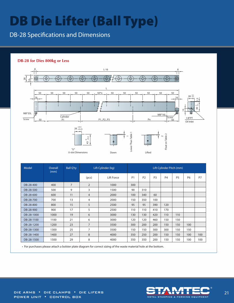
DB Die Lifter (Ball Type) DB-28 Speci�cations and Dimensions
Lift Cylinder (kg)
Lift Force
Lift Cylinder Pitch (mm)
P1 P2 P3 P4 P5 P6 P7
DB-28-400
DB-28-500
DB-28-600
DB-28-700
DB-28-800
DB-28-900
DB-28-1000
DB-28-1100
DB-28-1200
DB-28-1300
DB-28-1400
DB-28-1500
300
90
100
150
95
110
130
120
300
150
350
350
310
340
350
95
110
130
120
200
150
250
350
60
100
390
410
420
460
200
300
200
200
120
170
110
150
150
300
150
150
110
150
150
150
150
150
100
150
100
100
100
100
400
500
600
700
800
900
1000
1100
1200
1300
1400
1500
7
9
11
13
15
17
19
21
23
25
27
29
(pcs)
2
3
4
4
5
5
6
6
7
7
8
8
1000
1500
2000
2000
2500
2500
3000
3000
3500
3500
4000
4000
DB-28 for Dies 800kg or Less
50505050
L
16
Cylinder
13
40 0 -0
.1
50 50 50 50*n 50 50 50 50
16 28 -0.2-0.3
M8*16L Screw
M8*35L
50 P1 P1...P2...P3 Pn 50
1.5
14
8
28
L-16 8
1/8"PTOil Inlet
430 +
0.2
"U"U-slot Dimensions Down
1 2
Lifted
Overall(mm)
Model Ball Q'ty
28+0.5+0.25
Low
er T
han
Tabl
e 1
Floa
t on
Tabl
e 2
Screw
• For purchases please attach a bolster plate diagram for correct sizing of the waste material hole at the bottom.
METAL STAMPING & FORMING EQUIPMENT

DIE ARMS • DIE CLAMPS • DIE LIFERSPOWER UNIT • CONTROL BOX
DIE ARMS • DIE CLAMPS • DIE LIFERSPOWER UNIT • CONTROL BOX
20 13
This compact, space saving, piston type clamp requires U-slots on the die shoe. The clamp leg is machined to �t the T-slot on the bolster. With the TX Die Clamp automatic slide model remote control is made possible.
TX Die ClampsCompact, space-saving, wide range of applications
A
ØEC
D
Full
Stro
ke
Extr
a St
roke
Clamping Stroke
hF
A
BK
PT
ØG
ØM
A+1- 0
B +1- 0
D+0
.25
- 0.2
5C
+1 - 0
T-Slot Dimensions
Construction
T-Slot
Model Unit TX-25TX-16TX-10TX-6TX-4TX-2TX-1
1.10 (1)
0.20 (5)
0.10 (2.5)
0.10 (2.5)
2.7
2.21 (2)
0.32 (8)
0.16 (4)
0.16 (4)
6.5
4.41 (4)
0.32 (8)
0.12 (3)
0.20 (5)
13
6.95 (6.3)
0.32 (8)
0.12 (3)
0.20 (5)
21
11.02 (10)
0.32 (8)
0.12 (3)
0.20 5)
32
17.64 (16)
0.32 (8)
0.12 (3)
0.20 (5)
54
16.54 (15)
0.32 (8)
0.12 (3)
0.20 (5)
84
Clamping Force (at 250kgf / cm2)
Full Stroke (X)
Clamping Stroke (Y)
Extra Stroke (Z)
Cylinder Capacity at Full Stroke
US Tons (Metric Tons)
in. (mm)
in. (mm)
in. (mm)
cc.
• Extra stroke is the di�erence between full stroke and clamping stroke with extra space allowed for safe operation.
Power Unit Models
FP6308U- -
FP1014U- -
Model
TX-1
TX-2
TX-4
TX-6
TX-10
TX-16
TX-25
E
1.50 (38)
2.09 (53)
2.68 (68)
3.07 (78)
3.86 (98)
5.00 (127)
5.83 (148)
1.46 (37)
2.07 (52.5)
2.42 (61.5)
2.68 (68)
2.80 (71)
3.09 (78.5)
3.94 (100)
0.55 (14)
0.71 (18)
0.91 (23)
1.06 (27)
1.50 (38)
1.89 (48)
2.28 (58)
1.38 (35)
1.50 (38)
2.32 (59)
2.32 (59)
3.11 (79)
3.47 (88)
3.68 (98)
0.43 (11)
0.47 (12)
0.59 (15)
0.63 (16)
0.63 (16)
0.63 (16)
0.59 (15)
0.31 (8)
0.31 (8)
0.39 (10)
0.55 (14)
0.67 (17)
0.79 (20)
0.91 (23)
0.87 (22)
0.87 (22)
0.87 (22)
1.10 (28)
1.10 (28)
1.10 (28)
1.42 (36)
1.46 (37)
1.46 (37)
1.46 (37)
1.89 (48)
1.89 (48)
1.89 (48)
2.21 (56)
0.63 (16)
0.63 (16)
0.63 (16)
0.79 (20)
0.79 (20)
0.91 (23)
0.98 (25)
0.95 (24)
0.95 (24)
0.95 (24)
1.10 (28)
1.10 (28)
1.10 (28)
1.10 (28)
F
1/8
1/8
1/4
1/4
1/4
1/4
1/4
G M K PT A B C DMIN. C
Speci�cations
Dimensions
• in. (mm)• Die shoe thickness (h) classify: 0.98in. (25mm), 1.18in. (30mm), 1.38in. (35mm), 1.57in. (40mm), 1.77in. (45mm), 1.97in. (50mm), 2.17in. (55mm), 2.36in. (60mm).• Before purchase, please verify mold edge thickness (h) and T-slot (A. B. C. D.) has standard or special dimensions.
Overall(mm)
DL-50-400
DL-50-500
DL-50-600
DL-50-700
DL-50-800
DL-50-900
DL-50-1000
DL-50-1100
DL-50-1200
DL-50-1300
DL-50-1400
DL-50-1500
DL-50-1600
DL-50-1700
DL-50-1800
400
500
600
700
800
900
1000
1100
1200
1300
1400
1500
1600
1700
1800
800
1000
1200
1400
1600
1800
2000
2200
4600
5000
5400
5800
6200
6600
7000
2
3
4
4
4
4
5
5
5
6
6
7
7
8
8
2200
3300
4400
4400
4400
4400
5500
5500
5500
6600
6600
7700
7700
8800
8800
4
5
6
7
8
9
10
11
23
25
27
29
31
33
35
Die LoadCapacity
(kg)
Lift Cylinder
(pcs)
Lift Cylinder Pitch (mm)
P1
280
P2
90 290
90 330 60
140 340
170 390 120
100
210 400 170
125 125 410 220
150 150 400 280
150 150 400 380
150 150 200 400 280
150 150 200 400 380
150 150 200 300 300
100 150 250 400 300
100 100 150 250 300 380
Lift Force
100 100 150 250 300
280
280
300
300 480
P3 P4 P5 P6 P7
Model Roller Q'ty
Down
1 2
30
Lifted"U"
U-slot Dimensions
50 +0.5+0.25
+0.1+0
+0
.2+
053
12.5
25
50 100 100 100 100
L-25 12.5
L100xn 100 100 100 50
25
32
60 P1 P2...P3...P4...P5 Pn 60
13
4-M8X55L Cylinder
50-0 -0
.1
M6(Leveling Shim Provided)
Screw
Dust Keeper Roller49 0.1
1/8"PTOil Inlet
32
Low
er T
han
Tabl
e 1
Floa
t on
Tabl
e 2
• For purchases please attach a bolster plate diagram for correct sizing of the waste material hole at the bottom.
DL Die Lifter (Roller Type) DL-50 Speci�cations and Dimensions
METAL STAMPING & FORMING EQUIPMENT METAL STAMPING & FORMING EQUIPMENT

DIE ARMS • DIE CLAMPS • DIE LIFERSPOWER UNIT • CONTROL BOX
19
TY Die ClampsFits into the T-slot of the bolster for secure positioning.
Because this lever-type clamp does not require a U-slot on the die shoe it may be used in a wide range of applications. The base of the clamp is machined to �t the T-slot on the bolster. The �ange- mount model clamp may be bolted onto the bolster. The automatic slide model makes remote control possible.
• Before purchase, please verify mold edge thickness (h) and T-Slot (A.B.C.D.) has standard or special dimensions.
• 25 | 30 | 35 | 40 | 45 | 50 | 55 | 60 mm
• in. (mm)
K L PTP R BA C D
FP6308U- -
FP1014U- -
Power Unit
TY-1
TY-2
TY-4
TY-6
TY-10
TY-16
TY-25
1.95 (49.5)
2.32 (59)
3.35 (85)
3.70 (94)
4.13 (105)
4.72 (120)
5.24 (133)
F
1.18 (46)
2.48 (63)
3.43 (87)
3.82 (97)
4.33 (110)
5.12 (130)
5.91 (150)
G
0.79 (20)
1.10 (28)
1.58 (40)
1.73 (44)
1.97 (50)
2.36 (60)
2.87 (73)
0.59 (15)
0.87 (22)
0.98 (25)
1.16 (29.5)
1.10 (28)
1.18 (30)
1.18 (30)
2.28 (58)
3.35 (85)
4.72 (120)
5.24 (133)
6.50 (165)
7.87 (200)
9.45 (240)
2.87 (73)
4.21 (107)
5.71 (145)
6.40 (162.5)
6.65 (193)
9.06 (230)
10.63 (270)
0.39 (10)
0.39 (10)
0.39 (10)
0.43 (11)
0.43 (11)
0.47 (12)
0.51 (13)
0.39 (10)
0.49 (12.5)
0.63 (16)
0.79 (20)
0.79 (20)
0.79 (20)
0.79 (20)
1.34 (34)
1.89 (48)
2.28 (58)
2.68 (68)
3.22 (82)
3.78 (96)
4.33 (110)
0.65 (16.5)
1.06 (27)
1.30 (33)
1.58 (40)
2.09 (53)
2.64 (67)
3.19 (81)
1/8
1/8
1/4
1/4
1/4
1/4
1/4
0.28 (7)
0.37 (9.5)
0.47 (12)
0.55 (14)
0.65 (16.5)
0.75 (19)
0.87 (22)
0.87 (22)
0.87 (22)
0.87 (22)
1.10 (28)
1.10 (28)
1.10 (28)
1.42 (36)
1.46 (37)
1.46 (37)
1.46 (37)
1.89 (48)
1.89 (48)
1.89 (48)
2.21 (56)
0.63 (16)
0.63 (16)
0.63 (16)
0.79 (20)
0.79 (20)
0.91 (23)
0.98 (25)
0.95 (24)
0.95 (24)
0.95 (24)
1.10 (28)
1.10 (28)
1.10 (28)
1.10 (28)
JModel MIN. E MAX. N MIN. S MIN. C
T-Slot Dimensions
A +1- 0
C+1 - 0
D+0
.25
- 0.2
5
B +1- 0
G
EC
FL
J
Ph
PT
R
K
SN
Full
Stro
ke
Extr
a St
roke
Clam
ping
Str
oke
Construction
Speci�cations
Model Unit TY-25
25
0.32 (8)
0.12 (3)
0.20 (5)
93
TY-16
16
0.28 (7)
0.12 (3)
0.16 (4)
61
TY-10
10
0.32 (8)
0.12 (3)
0.20 (5)
37
TY-6
6.3
0.32 (8)
0.12 (3)
0.20 (5)
22.3
TY-4
4
0.28 (7)
0.12 (3)
0.16 (4)
13.2
TY-2
2
0.28 (7)
0.08 (2)
0.20 (5)
6.5
TY-1
1
0.24 (6)
0.12 (3)
0.12 (3)
2
Clamping Force (at 250kgf/cm2)
(X) Full Stroke
(Y) Clamping Stroke
(Z) Extra Stroke
Cylinder Capacity at Full Stroke
• Extra stroke is the di�erence between full stroke and clamping stroke with extra space allowed for safe operation.
tons
in. (mm)
in. (mm)
in. (mm)
cc.
DL Die Lifter (Roller Type) DL-28 Speci�cations and Dimensions
DL-28-400
DL-28-500
DL-28-600
DL-28-700
DL-28-800
DL-28-900
DL-28-1000
DL-28-1100
DL-28-1200
DL-28-1300
DL-28-1400
DL-28-1500
560
720
880
1040
1200
1360
1520
1680
1840
2000
2160
2320
400
500
600
700
800
900
1000
1100
1200
1300
1400
1500
7
9
11
13
15
17
19
21
23
25
27
29
2
3
4
4
5
5
6
6
7
7
8
8
1000
1500
2000
2000
2500
2500
3000
3000
3500
3500
4000
4000
300
90
100
150
95
110
130
150
100
150
100
100
310
340
350
95
110
130
150
150
150
100
100
60
100
390
410
420
460
150
300
150
150
120
170
110
120
200
300
150
150
110
120
200
150
200
200
300
150
250
350
350
350
Lift Cylinder
(pcs) Lift Force
Lift Cylinder Pitch (mm)
P1 P2 P3 P4
Roller Q'ty
P5 P6 P7
Die LoadCapacity
(kg)
28
14
8 L-16 8
Fixture
1 2
U-slot Dimensions"U"
LiftedDown
43+
0.2
+0
28+0.5+0.25 16
-0.1-0.2
Oil Pipe
13
28-0.2-0.3
1.5
40-0 -0
.1
Oil Inlet1/8"PT
12
Cylinder
Dust Keeper Roller16
50
M4(Leveling Shim Provided)
Screw
50 50 50 50
16
50 505050505050xnL
50 50
Screw
M8*10LP1 P2.P3...P7M8*40L
Overall(mm)
Model
Low
er T
han
Tabl
e 1
Floa
t on
Tabl
e 2
• For purchases please attach a bolster plate diagram for correct sizing of the waste material hole at the bottom.
METAL STAMPING & FORMING EQUIPMENT

DL Die Lifter (Roller Type) DL-22 Speci�cations and Dimensions
DIE ARMS • DIE CLAMPS • DIE LIFERSPOWER UNIT • CONTROL BOX
DIE ARMS • DIE CLAMPS • DIE LIFERSPOWER UNIT • CONTROL BOX
18 15
DR Die LiftersSpring-Loaded or Hydraulic Die Lifters
These spring-loaded die lifters easily �t to di�erent sized T or U-slots on the bolster by adding spacers to the side walls of the die lifters.
Die lifters are available in standard lengths of 200mm and 300mm, any die lifters length can be constructed by combining these standard lengths in increments of 100mm.
Speci�cations Width in. (mm)
DRL-22-200/ DRB-22-200
DRL-22-300/ DRB-22-300
DRL-28-200/ DRB-28-200
DRL-28-300/ DRB-28-300
0.87 (22)
0.87 (22)
1.10 (28)
1.10 (28)
Length in. (mm)
7.79 (200)
11.81 (300)
7.79 (200)
11.81 (300)
Springs (pcs)
4
6
4
6
Lift Force lbf (kgf )
82.67 (37.5)
82.67 (37.5)
165.35 (75)
165.35 (75)
• DRL-28/DRB-28 150°C• DRL-22/DRB-22 80°C
Construction and Action
Lifted Down
12
T-slot / U-slot Dimensionsa
H
a
H
Model a H
DR22 22
28
33~43
45~58DR28
DR -L 28 300-
Length
Width
7.79 in. (200 mm) 11.81 in. (300 mm)
0.87 in. (22 mm) 1.10 in. (28 mm)
ModelL ROLLB BALL
Die exceeding 1T is not applicable)
DL-22-300
DL-22-400
DL-22-500
DL-22-600
DL-22-700
DL-22-800
300
420
540
660
780
900
300
400
500
600
700
800
5
7
9
11
13
15
2
3
4
5
5
6
500
750
1000
1250
1250
1500
200
90
90
90
90
90
210
220
160
210
150
90
160
210
220
90
90
150 90
Lift Cylinder
(pcs) Lift Force
Lift Cylinder Pitch (mm)
P1 P2 P3 P4
Roller Q'ty
P5
Die LoadCapacity
(kg)
Overall(mm)
Model
• For purchases please attach a bolster plate diagram for correct sizing of the waste material hole at the bottom.
1111
22
8 L-16 8
Fixture
Oil Pipe
12
22-0.2-0.3
2
350 -0
.1
Oil Inlet1/8"PT
Cylinder
50
50 P1 P2...P5
50 50 50 50 50 50 50 50
50
1616
50xn
L
ScrewM6*35L
ScrewM6*10L
Roller
1 2
U-slot Dimensions"U"
LiftedDown
38+
0.2
0
22+0.5+0.25 10
Low
er T
han
Tabl
e 1
Floa
t on
Tabl
e 2
Basic Model
One Cylinder Capacity
Total Stroke
Working Hydraulic Pressure
Lifting Force Per cylinder
DL28
0.5
250
3
0.6
DL22
0.25
250
3
0.3
DL50
1.1
250
3
1.4
Unit
tons
kgf/cm2
mm
cc.
22DL -
Width
Overall Length400
METAL STAMPING & FORMING EQUIPMENT METAL STAMPING & FORMING EQUIPMENT
16 17
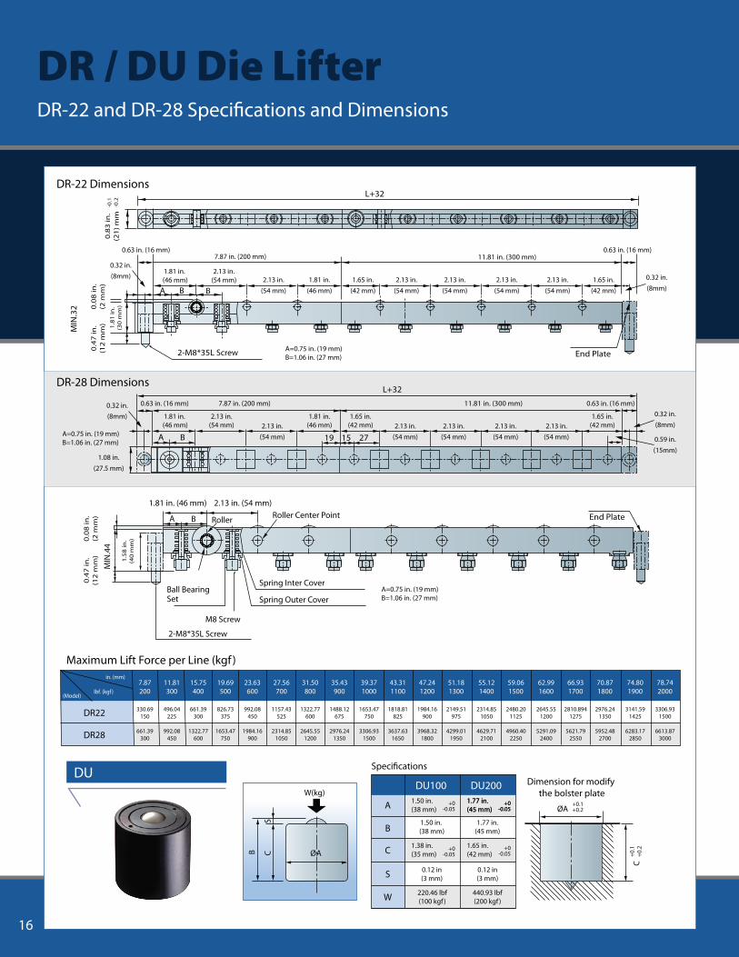
Maximum Lift Force per Line (kgf )
7.87200
11.81300
15.75400
19.69500
23.63600
27.56700
31.50800
35.43900
39.371000
43.311100
47.241200
51.181300
62.991600
59.061500
55.121400
66.931700
70.871800
74.801900
78.742000
330.69150
496.04225
992.08450
661.39300
1322.77600
826.73375
1653.47750
992.08450
1984.16900
1157.43525
2314.851050
1322.77600
2645.551200
1488.12675
2976.241350
1653.47750
3306.931500
1818.81825
3637.631650
1984.16900
3968.321800
2149.51975
4299.011950
2314.851050
4629.712100
2480.201125
4960.402250
2645.551200
5291.092400
2810.8941275
5621.792550
2976.241350
5952.482700
3141.591425
6283.172850
3306.931500
6613.873000
in. (mm)
lbf. (kgf )(Model)
DR22
DR28 661.39300
Speci�cations
Dimension for modify the bolster plate
1.65 in.(42 mm)
DU100
A
B
C
S
DU200
W
1.50 in. (38 mm)
1.38 in.(35 mm)
1.77 in.(45 mm)
1.50 in. (38 mm)
1.77 in.(45 mm)
0.12 in(3 mm)
0.12 in(3 mm)
440.93 lbf(200 kgf )
220.46 lbf(100 kgf )
+0-0.05
+0-0.05
+0-0.05
1.77 in.(45 mm)
+0-0.05
+0-0.05
2-M8*35L Screw
0.8
3 in
.(2
1) m
m-0
.2-0
.1
A B B
0.63 in. (16 mm)11.81 in. (300 mm)
L+32
MIN
.32
End Plate
0.4
7 in
.(1
2 m
m) 1.8
1 in
.(3
0 m
m)0.0
8 in
.(2
mm
)
7.87 in. (200 mm)0.63 in. (16 mm)
2.13 in.(54 mm)
2.13 in.(54 mm)
2.13 in.(54 mm)
2.13 in.(54 mm)
1.65 in.(42 mm)
1.65 in.(42 mm)
1.65 in.(42 mm)
1.81 in.(46 mm)
0.32 in.(8mm)
1.81 in. (46 mm) 2.13 in.
(54 mm)
2.13 in.(54 mm)
A B 271519
MIN
.44
1.81 in. (46 mm)
BA
2.13 in. (54 mm)
Ball Bearing
Roller Roller Center Point
Spring Inter Cover
Spring Outer Cover
M8 Screw
2-M8*35L Screw
Set
End Plate
L+32
S
B C ØA
W(kg)
ØA+0.1+0.2
C+0
.2+0
.1
DU
DR-28 Dimensions
DR-22 Dimensions
0.32 in.(8mm)
0.32 in.(8mm)
1.08 in.(27.5 mm)
A=0.75 in. (19 mm)B=1.06 in. (27 mm)
A=0.75 in. (19 mm)B=1.06 in. (27 mm)
0.63 in. (16 mm) 11.81 in. (300 mm)7.87 in. (200 mm) 0.63 in. (16 mm)0.32 in.(8mm)
0.59 in.(15mm)
1.81 in.(46 mm)
1.81 in. (46 mm) 2.13 in.
(54 mm)
2.13 in.(54 mm) 2.13 in.
(54 mm)2.13 in.
(54 mm)2.13 in.
(54 mm)2.13 in.
(54 mm)
1.65 in.(42 mm)
A=0.75 in. (19 mm)B=1.06 in. (27 mm)
0.4
7 in
.(1
2 m
m)
0.0
8 in
.(2
mm
)
1.5
8 in
.(4
0 m
m)
Quote Request ForQuotes for more than one press, please use this form for each machine.
New or Existing New ExistingA1
Manufacturer and Model Manufacturer ModelA2
Type of Press C Frame Straight Side
A3Transfer Other Specify
Tonnage tf USA4 Metric
Slide Dimensions (L-R) X (F-B) mm (inch)A5
mm (inch)
(W) x (L) mm (inch)x (H)
(L-R) X (F-B) mm (inch)Bolster DimensionsA6
T-slot Yes
kg (1bs)
NoA7
B1
B2
B3
B4
B5
B6
Yes No
Manual Automatic
Power Supply AC DC Volt Hz
Plain Lattice
Max. Weight
C1 Required Components
C2 Valve Operation
Max. Dimensions
U-slot for Bolting
Die Shoe Thickness
Bottom
Special Requirements
Clamp Model X pcs
Die Lifter Model X pcs
Die Arm Model X pcs
Power Unit Model X pcs
COMPANY : NAME :
ADDR :
TEL : FAX :
Pres
s Pa
rts
A
Die
Par
ts
B
Die
Cha
nge
Syst
em
Part
s
C
Your Information
DR / DU Die Lifter DR-22 and DR-28 Speci�cations and Dimensions

16 17
Maximum Lift Force per Line (kgf )
7.87200
11.81300
15.75400
19.69500
23.63600
27.56700
31.50800
35.43900
39.371000
43.311100
47.241200
51.181300
62.991600
59.061500
55.121400
66.931700
70.871800
74.801900
78.742000
330.69150
496.04225
992.08450
661.39300
1322.77600
826.73375
1653.47750
992.08450
1984.16900
1157.43525
2314.851050
1322.77600
2645.551200
1488.12675
2976.241350
1653.47750
3306.931500
1818.81825
3637.631650
1984.16900
3968.321800
2149.51975
4299.011950
2314.851050
4629.712100
2480.201125
4960.402250
2645.551200
5291.092400
2810.8941275
5621.792550
2976.241350
5952.482700
3141.591425
6283.172850
3306.931500
6613.873000
in. (mm)
lbf. (kgf )(Model)
DR22
DR28 661.39300
Speci�cations
Dimension for modify the bolster plate
1.65 in.(42 mm)
DU100
A
B
C
S
DU200
W
1.50 in. (38 mm)
1.38 in.(35 mm)
1.77 in.(45 mm)
1.50 in. (38 mm)
1.77 in.(45 mm)
0.12 in(3 mm)
0.12 in(3 mm)
440.93 lbf(200 kgf )
220.46 lbf(100 kgf )
+0-0.05
+0-0.05
+0-0.05
1.77 in.(45 mm)
+0-0.05
+0-0.05
2-M8*35L Screw
0.8
3 in
.(2
1) m
m-0
.2-0
.1
A B B
0.63 in. (16 mm)11.81 in. (300 mm)
L+32
MIN
.32
End Plate
0.4
7 in
.(1
2 m
m) 1.8
1 in
.(3
0 m
m)0.0
8 in
.(2
mm
)
7.87 in. (200 mm)0.63 in. (16 mm)
2.13 in.(54 mm)
2.13 in.(54 mm)
2.13 in.(54 mm)
2.13 in.(54 mm)
1.65 in.(42 mm)
1.65 in.(42 mm)
1.65 in.(42 mm)
1.81 in.(46 mm)
0.32 in.(8mm)
1.81 in. (46 mm) 2.13 in.
(54 mm)
2.13 in.(54 mm)
A B 271519
MIN
.44
1.81 in. (46 mm)
BA
2.13 in. (54 mm)
Ball Bearing
Roller Roller Center Point
Spring Inter Cover
Spring Outer Cover
M8 Screw
2-M8*35L Screw
Set
End Plate
L+32
S
B C ØA
W(kg)
ØA+0.1+0.2
C+0
.2+0
.1
DU
DR-28 Dimensions
DR-22 Dimensions
0.32 in.(8mm)
0.32 in.(8mm)
1.08 in.(27.5 mm)
A=0.75 in. (19 mm)B=1.06 in. (27 mm)
A=0.75 in. (19 mm)B=1.06 in. (27 mm)
0.63 in. (16 mm) 11.81 in. (300 mm)7.87 in. (200 mm) 0.63 in. (16 mm)0.32 in.(8mm)
0.59 in.(15mm)
1.81 in.(46 mm)
1.81 in. (46 mm) 2.13 in.
(54 mm)
2.13 in.(54 mm) 2.13 in.
(54 mm)2.13 in.
(54 mm)2.13 in.
(54 mm)2.13 in.
(54 mm)
1.65 in.(42 mm)
A=0.75 in. (19 mm)B=1.06 in. (27 mm)
0.4
7 in
.(1
2 m
m)
0.0
8 in
.(2
mm
)
1.5
8 in
.(4
0 m
m)
Quote Request ForQuotes for more than one press, please use this form for each machine.
New or Existing New ExistingA1
Manufacturer and Model Manufacturer ModelA2
Type of Press C Frame Straight Side
A3Transfer Other Specify
Tonnage tf USA4 Metric
Slide Dimensions (L-R) X (F-B) mm (inch)A5
mm (inch)
(W) x (L) mm (inch)x (H)
(L-R) X (F-B) mm (inch)Bolster DimensionsA6
T-slot Yes
kg (1bs)
NoA7
B1
B2
B3
B4
B5
B6
Yes No
Manual Automatic
Power Supply AC DC Volt Hz
Plain Lattice
Max. Weight
C1 Required Components
C2 Valve Operation
Max. Dimensions
U-slot for Bolting
Die Shoe Thickness
Bottom
Special Requirements
Clamp Model X pcs
Die Lifter Model X pcs
Die Arm Model X pcs
Power Unit Model X pcs
COMPANY : NAME :
ADDR :
TEL : FAX :
Pres
s Pa
rts
A
Die
Par
ts
B
Die
Cha
nge
Syst
em
Part
s
C
Your Information
DR / DU Die Lifter DR-22 and DR-28 Speci�cations and Dimensions

DL Die Lifter (Roller Type) DL-22 Speci�cations and Dimensions
DIE ARMS • DIE CLAMPS • DIE LIFERSPOWER UNIT • CONTROL BOX
DIE ARMS • DIE CLAMPS • DIE LIFERSPOWER UNIT • CONTROL BOX
18 15
DR Die LiftersSpring-Loaded or Hydraulic Die Lifters
These spring-loaded die lifters easily �t to di�erent sized T or U-slots on the bolster by adding spacers to the side walls of the die lifters.
Die lifters are available in standard lengths of 200mm and 300mm, any die lifters length can be constructed by combining these standard lengths in increments of 100mm.
Speci�cations Width in. (mm)
DRL-22-200/ DRB-22-200
DRL-22-300/ DRB-22-300
DRL-28-200/ DRB-28-200
DRL-28-300/ DRB-28-300
0.87 (22)
0.87 (22)
1.10 (28)
1.10 (28)
Length in. (mm)
7.79 (200)
11.81 (300)
7.79 (200)
11.81 (300)
Springs (pcs)
4
6
4
6
Lift Force lbf (kgf )
82.67 (37.5)
82.67 (37.5)
165.35 (75)
165.35 (75)
• DRL-28/DRB-28 150°C• DRL-22/DRB-22 80°C
Construction and Action
Lifted Down
12
T-slot / U-slot Dimensionsa
H
a
H
Model a H
DR22 22
28
33~43
45~58DR28
DR -L 28 300-
Length
Width
7.79 in. (200 mm) 11.81 in. (300 mm)
0.87 in. (22 mm) 1.10 in. (28 mm)
ModelL ROLLB BALL
Die exceeding 1T is not applicable)
DL-22-300
DL-22-400
DL-22-500
DL-22-600
DL-22-700
DL-22-800
300
420
540
660
780
900
300
400
500
600
700
800
5
7
9
11
13
15
2
3
4
5
5
6
500
750
1000
1250
1250
1500
200
90
90
90
90
90
210
220
160
210
150
90
160
210
220
90
90
150 90
Lift Cylinder
(pcs) Lift Force
Lift Cylinder Pitch (mm)
P1 P2 P3 P4
Roller Q'ty
P5
Die LoadCapacity
(kg)
Overall(mm)
Model
• For purchases please attach a bolster plate diagram for correct sizing of the waste material hole at the bottom.
1111
22
8 L-16 8
Fixture
Oil Pipe
12
22-0.2-0.3
2
350 -0
.1
Oil Inlet1/8"PT
Cylinder
50
50 P1 P2...P5
50 50 50 50 50 50 50 50
50
1616
50xn
L
ScrewM6*35L
ScrewM6*10L
Roller
1 2
U-slot Dimensions"U"
LiftedDown
38+
0.2
0
22+0.5+0.25 10
Low
er T
han
Tabl
e 1
Floa
t on
Tabl
e 2
Basic Model
One Cylinder Capacity
Total Stroke
Working Hydraulic Pressure
Lifting Force Per cylinder
DL28
0.5
250
3
0.6
DL22
0.25
250
3
0.3
DL50
1.1
250
3
1.4
Unit
tons
kgf/cm2
mm
cc.
22DL -
Width
Overall Length400
METAL STAMPING & FORMING EQUIPMENT METAL STAMPING & FORMING EQUIPMENT

DIE ARMS • DIE CLAMPS • DIE LIFERSPOWER UNIT • CONTROL BOX
19
TY Die ClampsFits into the T-slot of the bolster for secure positioning.
Because this lever-type clamp does not require a U-slot on the die shoe it may be used in a wide range of applications. The base of the clamp is machined to �t the T-slot on the bolster. The �ange- mount model clamp may be bolted onto the bolster. The automatic slide model makes remote control possible.
• Before purchase, please verify mold edge thickness (h) and T-Slot (A.B.C.D.) has standard or special dimensions.
• 25 | 30 | 35 | 40 | 45 | 50 | 55 | 60 mm
• in. (mm)
K L PTP R BA C D
FP6308U- -
FP1014U- -
Power Unit
TY-1
TY-2
TY-4
TY-6
TY-10
TY-16
TY-25
1.95 (49.5)
2.32 (59)
3.35 (85)
3.70 (94)
4.13 (105)
4.72 (120)
5.24 (133)
F
1.18 (46)
2.48 (63)
3.43 (87)
3.82 (97)
4.33 (110)
5.12 (130)
5.91 (150)
G
0.79 (20)
1.10 (28)
1.58 (40)
1.73 (44)
1.97 (50)
2.36 (60)
2.87 (73)
0.59 (15)
0.87 (22)
0.98 (25)
1.16 (29.5)
1.10 (28)
1.18 (30)
1.18 (30)
2.28 (58)
3.35 (85)
4.72 (120)
5.24 (133)
6.50 (165)
7.87 (200)
9.45 (240)
2.87 (73)
4.21 (107)
5.71 (145)
6.40 (162.5)
6.65 (193)
9.06 (230)
10.63 (270)
0.39 (10)
0.39 (10)
0.39 (10)
0.43 (11)
0.43 (11)
0.47 (12)
0.51 (13)
0.39 (10)
0.49 (12.5)
0.63 (16)
0.79 (20)
0.79 (20)
0.79 (20)
0.79 (20)
1.34 (34)
1.89 (48)
2.28 (58)
2.68 (68)
3.22 (82)
3.78 (96)
4.33 (110)
0.65 (16.5)
1.06 (27)
1.30 (33)
1.58 (40)
2.09 (53)
2.64 (67)
3.19 (81)
1/8
1/8
1/4
1/4
1/4
1/4
1/4
0.28 (7)
0.37 (9.5)
0.47 (12)
0.55 (14)
0.65 (16.5)
0.75 (19)
0.87 (22)
0.87 (22)
0.87 (22)
0.87 (22)
1.10 (28)
1.10 (28)
1.10 (28)
1.42 (36)
1.46 (37)
1.46 (37)
1.46 (37)
1.89 (48)
1.89 (48)
1.89 (48)
2.21 (56)
0.63 (16)
0.63 (16)
0.63 (16)
0.79 (20)
0.79 (20)
0.91 (23)
0.98 (25)
0.95 (24)
0.95 (24)
0.95 (24)
1.10 (28)
1.10 (28)
1.10 (28)
1.10 (28)
JModel MIN. E MAX. N MIN. S MIN. C
T-Slot Dimensions
A +1- 0
C+1 - 0
D+0
.25
- 0.2
5
B +1- 0
G
EC
FL
J
Ph
PT
R
K
SN
Full
Stro
ke
Extr
a St
roke
Clam
ping
Str
oke
Construction
Speci�cations
Model Unit TY-25
25
0.32 (8)
0.12 (3)
0.20 (5)
93
TY-16
16
0.28 (7)
0.12 (3)
0.16 (4)
61
TY-10
10
0.32 (8)
0.12 (3)
0.20 (5)
37
TY-6
6.3
0.32 (8)
0.12 (3)
0.20 (5)
22.3
TY-4
4
0.28 (7)
0.12 (3)
0.16 (4)
13.2
TY-2
2
0.28 (7)
0.08 (2)
0.20 (5)
6.5
TY-1
1
0.24 (6)
0.12 (3)
0.12 (3)
2
Clamping Force (at 250kgf/cm2)
(X) Full Stroke
(Y) Clamping Stroke
(Z) Extra Stroke
Cylinder Capacity at Full Stroke
• Extra stroke is the di�erence between full stroke and clamping stroke with extra space allowed for safe operation.
tons
in. (mm)
in. (mm)
in. (mm)
cc.
DL Die Lifter (Roller Type) DL-28 Speci�cations and Dimensions
DL-28-400
DL-28-500
DL-28-600
DL-28-700
DL-28-800
DL-28-900
DL-28-1000
DL-28-1100
DL-28-1200
DL-28-1300
DL-28-1400
DL-28-1500
560
720
880
1040
1200
1360
1520
1680
1840
2000
2160
2320
400
500
600
700
800
900
1000
1100
1200
1300
1400
1500
7
9
11
13
15
17
19
21
23
25
27
29
2
3
4
4
5
5
6
6
7
7
8
8
1000
1500
2000
2000
2500
2500
3000
3000
3500
3500
4000
4000
300
90
100
150
95
110
130
150
100
150
100
100
310
340
350
95
110
130
150
150
150
100
100
60
100
390
410
420
460
150
300
150
150
120
170
110
120
200
300
150
150
110
120
200
150
200
200
300
150
250
350
350
350
Lift Cylinder
(pcs) Lift Force
Lift Cylinder Pitch (mm)
P1 P2 P3 P4
Roller Q'ty
P5 P6 P7
Die LoadCapacity
(kg)
28
14
8 L-16 8
Fixture
1 2
U-slot Dimensions"U"
LiftedDown
43+
0.2
+0
28+0.5+0.25 16
-0.1-0.2
Oil Pipe
13
28-0.2-0.3
1.5
40-0 -0
.1
Oil Inlet1/8"PT
12
Cylinder
Dust Keeper Roller16
50
M4(Leveling Shim Provided)
Screw
50 50 50 50
16
50 505050505050xnL
50 50
Screw
M8*10LP1 P2.P3...P7M8*40L
Overall(mm)
Model
Low
er T
han
Tabl
e 1
Floa
t on
Tabl
e 2
• For purchases please attach a bolster plate diagram for correct sizing of the waste material hole at the bottom.
METAL STAMPING & FORMING EQUIPMENT

DIE ARMS • DIE CLAMPS • DIE LIFERSPOWER UNIT • CONTROL BOX
DIE ARMS • DIE CLAMPS • DIE LIFERSPOWER UNIT • CONTROL BOX
20 13
This compact, space saving, piston type clamp requires U-slots on the die shoe. The clamp leg is machined to �t the T-slot on the bolster. With the TX Die Clamp automatic slide model remote control is made possible.
TX Die ClampsCompact, space-saving, wide range of applications
A
ØE
CD
Full
Stro
ke
Extr
a St
roke
Clamping Stroke
hF
A
B
K
PT
ØG
ØM
A+1- 0
B +1- 0
D+0
.25
- 0.2
5C
+1 - 0
T-Slot Dimensions
Construction
T-Slot
Model Unit TX-25TX-16TX-10TX-6TX-4TX-2TX-1
1.10 (1)
0.20 (5)
0.10 (2.5)
0.10 (2.5)
2.7
2.21 (2)
0.32 (8)
0.16 (4)
0.16 (4)
6.5
4.41 (4)
0.32 (8)
0.12 (3)
0.20 (5)
13
6.95 (6.3)
0.32 (8)
0.12 (3)
0.20 (5)
21
11.02 (10)
0.32 (8)
0.12 (3)
0.20 5)
32
17.64 (16)
0.32 (8)
0.12 (3)
0.20 (5)
54
16.54 (15)
0.32 (8)
0.12 (3)
0.20 (5)
84
Clamping Force (at 250kgf / cm2)
Full Stroke (X)
Clamping Stroke (Y)
Extra Stroke (Z)
Cylinder Capacity at Full Stroke
US Tons (Metric Tons)
in. (mm)
in. (mm)
in. (mm)
cc.
• Extra stroke is the di�erence between full stroke and clamping stroke with extra space allowed for safe operation.
Power Unit Models
FP6308U- -
FP1014U- -
Model
TX-1
TX-2
TX-4
TX-6
TX-10
TX-16
TX-25
E
1.50 (38)
2.09 (53)
2.68 (68)
3.07 (78)
3.86 (98)
5.00 (127)
5.83 (148)
1.46 (37)
2.07 (52.5)
2.42 (61.5)
2.68 (68)
2.80 (71)
3.09 (78.5)
3.94 (100)
0.55 (14)
0.71 (18)
0.91 (23)
1.06 (27)
1.50 (38)
1.89 (48)
2.28 (58)
1.38 (35)
1.50 (38)
2.32 (59)
2.32 (59)
3.11 (79)
3.47 (88)
3.68 (98)
0.43 (11)
0.47 (12)
0.59 (15)
0.63 (16)
0.63 (16)
0.63 (16)
0.59 (15)
0.31 (8)
0.31 (8)
0.39 (10)
0.55 (14)
0.67 (17)
0.79 (20)
0.91 (23)
0.87 (22)
0.87 (22)
0.87 (22)
1.10 (28)
1.10 (28)
1.10 (28)
1.42 (36)
1.46 (37)
1.46 (37)
1.46 (37)
1.89 (48)
1.89 (48)
1.89 (48)
2.21 (56)
0.63 (16)
0.63 (16)
0.63 (16)
0.79 (20)
0.79 (20)
0.91 (23)
0.98 (25)
0.95 (24)
0.95 (24)
0.95 (24)
1.10 (28)
1.10 (28)
1.10 (28)
1.10 (28)
F
1/8
1/8
1/4
1/4
1/4
1/4
1/4
G M K PT A B C DMIN. C
Speci�cations
Dimensions
• in. (mm)• Die shoe thickness (h) classify: 0.98in. (25mm), 1.18in. (30mm), 1.38in. (35mm), 1.57in. (40mm), 1.77in. (45mm), 1.97in. (50mm), 2.17in. (55mm), 2.36in. (60mm).• Before purchase, please verify mold edge thickness (h) and T-slot (A. B. C. D.) has standard or special dimensions.
Overall(mm)
DL-50-400
DL-50-500
DL-50-600
DL-50-700
DL-50-800
DL-50-900
DL-50-1000
DL-50-1100
DL-50-1200
DL-50-1300
DL-50-1400
DL-50-1500
DL-50-1600
DL-50-1700
DL-50-1800
400
500
600
700
800
900
1000
1100
1200
1300
1400
1500
1600
1700
1800
800
1000
1200
1400
1600
1800
2000
2200
4600
5000
5400
5800
6200
6600
7000
2
3
4
4
4
4
5
5
5
6
6
7
7
8
8
2200
3300
4400
4400
4400
4400
5500
5500
5500
6600
6600
7700
7700
8800
8800
4
5
6
7
8
9
10
11
23
25
27
29
31
33
35
Die LoadCapacity
(kg)
Lift Cylinder
(pcs)
Lift Cylinder Pitch (mm)
P1
280
P2
90 290
90 330 60
140 340
170 390 120
100
210 400 170
125 125 410 220
150 150 400 280
150 150 400 380
150 150 200 400 280
150 150 200 400 380
150 150 200 300 300
100 150 250 400 300
100 100 150 250 300 380
Lift Force
100 100 150 250 300
280
280
300
300 480
P3 P4 P5 P6 P7
Model Roller Q'ty
Down
1 2
30
Lifted"U"
U-slot Dimensions
50 +0.5+0.25
+0.1+0
+0
.2+
053
12.5
25
50 100 100 100 100
L-25 12.5
L100xn 100 100 100 50
25
32
60 P1 P2...P3...P4...P5 Pn 60
13
4-M8X55L Cylinder
50-0 -0
.1
M6(Leveling Shim Provided)
Screw
Dust Keeper Roller49 0.1
1/8"PTOil Inlet
32
Low
er T
han
Tabl
e 1
Floa
t on
Tabl
e 2
• For purchases please attach a bolster plate diagram for correct sizing of the waste material hole at the bottom.
DL Die Lifter (Roller Type) DL-50 Speci�cations and Dimensions
METAL STAMPING & FORMING EQUIPMENT METAL STAMPING & FORMING EQUIPMENT
DIE ARMS • DIE CLAMPS • DIE LIFERSPOWER UNIT • CONTROL BOX
12 21
Power UnitsFP100 Power Unit Speci�cations
20
FP1008 0.9 I/min, Pressure Ratio 1:130
0 1 2 3 4 5 6 7700
500
600
400
300
200
0
100
0 0.2 0.4 0.6 0.8 1.0 1.2 1.4
5kg / cm2
FP1009 1.15 I/min, Pressure Ratio 1:100
700
500
600
400
300
200
0
100
0 1 2 3 4 5 6 7
0 0.2 0.4 0.6 0.8 1.0 1.2 1.4
5kg / cm2
FP1012 2.04 I/min, Pressure Ratio 1:60
0 1 2 3 4 5 6 7350
250
300
200
150
100
0
50
0 1 2 3 4 5 6 7
5kg / cm2
FP1014 2.88 I/min, Pressure Ratio 1:50
0 1 2 3 4 5 6 7
0 1 2 3 4 5 6 7
350
250
300
200
150
100
50
0
5kg / cm2
FP1018 4 I/min, Pressure Ratio 1:25
0 1 2 3 4 5 6 7175
125
150
100
75
50
25
00 1 2 3 4 5 6 7
5kg / cm2
FP1018 8.14 I/minn, Pressure Ratio 1:12
0 1 2 3 4 5 6 7
0 2 4 6 8 10 12 14
70
50
60
40
30
20
10
0
5kg / cm2
9.17 in. (233 mm)
9.13
in. (
232
mm
)
4.53 in. (115 mm)
3.74 in. (95 mm)
3/8"PT
3/8"PT
Diagonally Locked Tight
Ø11-2
Ø50
kg / cm2 (PH)
Pres
sure
Out
put
kg / cm2 (PH)
Pres
sure
Out
put
kg / cm2 (PH)
Pres
sure
Out
put
kg / cm2 (PH)
Pres
sure
Out
put
kg / cm2 (PH)
Pres
sure
Out
put
kg / cm2 (PH)
Pres
sure
Out
put
Ø11-2 Hole
• Pressure : Flow characteristics tables provided below for your reference.
MAX = 0.8Nm3 / min. (8e-22cm3 / min.)
Air consumption MAX = 0.8Nm3 / min. (8e-22cm3 / min.)
Please refer to instructions for large �ow.
Speci�cations are subject to change. Please give us a call at 931-393-5050to con�rm values.
Drive Fluid
Weight
Lubricant
Operating Temperature
Air Pressure
(ISO VG32-VG68)Standard hydraulic oil
2~6 kg / cm2 (2~6 bar)
Air
-5°~60°C
24.25 lbs. (11 kg)
Oil Volume Output (I/min) Oil Volume Output (I/min)Oil Volume Output (I/min)
Oil Volume Output (I/min) Oil Volume Output (I/min)Oil Volume Output (I/min)
Pressure kg / cm2 (PA) Pressure kg / cm2 (PA)Pressure kg / cm2 (PA)
Pressure kg / cm2 (PA) Pressure kg / cm2 (PA)Pressure kg / cm2 (PA)
4.53
in. (
115
mm
)
3.74
in. (
95 m
m)
DB Die Lifter (Ball Type) DB-28 Speci�cations and Dimensions
Lift Cylinder (kg)
Lift Force
Lift Cylinder Pitch (mm)
P1 P2 P3 P4 P5 P6 P7
DB-28-400
DB-28-500
DB-28-600
DB-28-700
DB-28-800
DB-28-900
DB-28-1000
DB-28-1100
DB-28-1200
DB-28-1300
DB-28-1400
DB-28-1500
300
90
100
150
95
110
130
120
300
150
350
350
310
340
350
95
110
130
120
200
150
250
350
60
100
390
410
420
460
200
300
200
200
120
170
110
150
150
300
150
150
110
150
150
150
150
150
100
150
100
100
100
100
400
500
600
700
800
900
1000
1100
1200
1300
1400
1500
7
9
11
13
15
17
19
21
23
25
27
29
(pcs)
2
3
4
4
5
5
6
6
7
7
8
8
1000
1500
2000
2000
2500
2500
3000
3000
3500
3500
4000
4000
DB-28 for Dies 800kg or Less
50505050
L
16
Cylinder
13
40 0 -0
.1
50 50 50 50*n 50 50 50 50
16 28 -0.2-0.3
M8*16L Screw
M8*35L
50 P1 P1...P2...P3 Pn 50
1.5
14
8
28
L-16 8
1/8"PTOil Inlet
430 +
0.2
"U"U-slot Dimensions Down
1 2
Lifted
Overall(mm)
Model Ball Q'ty
28+0.5+0.25
Low
er T
han
Tabl
e 1
Floa
t on
Tabl
e 2
Screw
• For purchases please attach a bolster plate diagram for correct sizing of the waste material hole at the bottom.
METAL STAMPING & FORMING EQUIPMENT

DB Die Lifter (Ball Type) DB-50 Speci�cations and Dimensions
DIE ARMS • DIE CLAMPS • DIE LIFERSPOWER UNIT • CONTROL BOX
22 11
Power UnitsFP63 Power Unit Speci�cations
0 1 2 3 4 5 6 7
Oil Volume Output (I/min) Oil Volume Output (I/min) Oil Volume Output (I/min)
Oil Volume Output (I/min) Oil Volume Output (I/min) Oil Volume Output (I/min)
Oil Volume Output (I/min) Oil Volume Output (I/min) Oil Volume Output (I/min)
FP-6309 0.9 I/min, Pressure Ratio 1:40Pressure kg / cm2 (PA)
FP-6314 2.2 I/min, Pressure Ratio 1:16Pressure kg / cm2 (PA)
FP-6307 0.6 I/min, Pressure Ratio 1:60FP-6306 0.45 I/min, Pressure Ratio 1:84Pressure kg / cm2 (PA) Pressure kg / cm2 (PA)
FP-6310 1.1 I/min, Pressure Ratio 1:30Pressure kg / cm2 (PA)
FP-6308 0.7 I/min, Pressure Ratio 1:50Pressure kg / cm2 (PA)
FP-6312 1.7 I/min, Pressure Ratio 1:20Pressure kg / cm2 (PA)
FP-6320 4.5 I/min, Pressure Ratio 1:8Pressure kg / cm2 (PA)
0 0.1 0.2 0.3 0.4 0.5 0.6 0.7
700
600
500
400
300
200
100
0
0 1 2 3 4 5 6 7
0 0.1 0.2 0.3 0.4 0.5 0.6 0.7
700
600
500
400
300
200
100
0
0 1 2 3 4 5 6 7250
200
150
100
50
00 0.2 0.4 0.6 0.8 1.0 1.2 1.4
0 1 2 3 4 5 6 7
0 1 2 3 4 5 6 7120
100
80
60
40
20
00 0.5 1 1.5 2 2.5 3 3.5
250
200
150
100
50
00 0.2 0.4 0.6 0.8 1.0 1.2 1.4
5kg / cm2
5kg / cm2
0 1 2 3 4 5 6 7 8400
300
200
100
0 0 0.1 0.2 0.3 0.4 0.5 0.6 0.7 0.8
5kg / cm2
0 1 2 3 4 5 6 7150
125
100
75
50
25
00 0.3 0.6 0.9 1.2 1.5 1.8 2.1
5kg / cm25kg / cm25kg / cm2
5kg / cm2
FP-6316 2.7 I/min, Pressure Ratio 1:10Pressure kg / cm2 (PA)
0 1 2 3 4 5 6 7
80
100
60
40
20
00 0.5 1 1.5 2 2.5 3 3.5
5kg / cm2
0 1 2 3 4 5 6 770
60
50
40
30
20
10
00 1 2 3 4 5 6 7
5kg / cm2
7.21 in. (183 mm)
6.85
in. (
174
mm
)
Ø9-4 Hole
Ø9-4
Ø33
3.23
in. (
82 m
m)
2.36
in. (
60 m
m)
4.74 in. (120 mm)3.94 in. (100 mm)
5.35
in. (
136
mm
)
1/4"PT
1/4"PT
• Pressure : Flow characteristics tables provided below for your reference.
MAX = 0.35Nm3 / min. (3.5e-22cm3 / min.)
Air consumption MAX = 0.35Nm3 / min. (3.5e-22cm3 / min.)
Please refer to instructions for large �ow.
Speci�cations are subject to change. Please give us a call at 931-393-5050to con�rm values.
Drive Fluid
Weight
Lubricant
Operating Temperature
Air Pressure
(ISO VG32-VG68)Standard hydraulic oil
2~6 kg / cm2 (2~6 bar)
Air
-5°~60°C
8.82 lbs. (4 kg)
kg / cm2 (PH)
Pres
sure
Out
put
kg / cm2 (PH)
Pres
sure
Out
put
kg / cm2 (PH)
Pres
sure
Out
put
kg / cm2 (PH)
Pres
sure
Out
put
kg / cm2 (PH)
Pres
sure
Out
put
kg / cm2 (PH)
Pres
sure
Out
put
kg / cm2 (PH)
Pres
sure
Out
put
kg / cm2 (PH)
Pres
sure
Out
put
kg / cm2 (PH)
Pres
sure
Out
put
Overall(mm)
DB-50-400
DB-50-500
DB-50-600
DB-50-700
DB-50-800
DB-50-900
DB-50-1000
DB-50-1100
DB-50-1200
DB-50-1300
DB-50-1400
DB-50-1500
DB-50-1600
DB-50-1700
DB-50-1800
400
500
600
700
800
900
1000
1100
1200
1300
1400
1500
1600
1700
1800
2
3
4
4
4
4
5
5
5
6
6
7
7
8
8
2200
3300
4400
4400
4400
4400
5500
5500
5500
6600
6600
7700
7700
8800
8800
280
90
90
140
170
210
125
150
150
150
150
150
100
100
100
290
330
340
390
400
125
150
150
150
150
150
150
100
100
60
100
120
170
410
400
400
200
200
200
250
150
150
220
280
380
400
400
300
400
250
250
280
380
300
300
300
300
280
280
300
300
380
480
7
9
11
13
15
17
19
21
23
25
27
29
31
33
35
Lift Cylinder (kg)
pcs
Lift Cylinder Pitch (mm)
P1 P2Lift Force (kgf) P3 P4 P5 P6 P7
Model Ball Q'ty
2
50
1
50+0.25+0.5
530 +0
.2
L
25
Cylinder
60
L-25
PnP2...P3....P4....P1
50
3213
4-M8X55L
25
50
12.5 12.5
60
49 0.1
50-0 -0
.1
1/8"PT
50 50 50 50 50 50 50*N 50 50 50 50 50
Screw
Oil Inlet
U- Slot Dimensions"U"
Normal Status Lifted
Low
er T
han
Tabl
e 1
Floa
t on
Tabl
e 2
M6 (Leveling Shim Provided)
DB-50 for Dies 800~1500kg
• For purchases please attach a bolster plate diagram for correct sizing of the waste material hole at the bottom.
METAL STAMPING & FORMING EQUIPMENT

Hydraulic Power UnitsFP63 and FP100 Pump Speci�cations
DIE ARMS • DIE CLAMPS • DIE LIFERSPOWER UNIT • CONTROL BOX
DIE ARMS • DIE CLAMPS • DIE LIFERSPOWER UNIT • CONTROL BOX
10 23
ModelTotal
Circuits
1
2
3
4
13.90 in. (353 mm)
13.90 in. (353 mm)
16.65 in. (423 mm)
19.41 in. (493 mm)
15.47 in. (393 mm)
15.47 in. (393 mm)
18.23 in. (463 mm)
20.98 in. (533 mm)
6
6
7.5
9
4.7
4.7
5.9
7.1
50.71 lbs. (23 kg)
59.53 lbs. (27 kg)
77.16 lbs. (35 kg)
94.80 lbs. (43 kg)
A BReservoirCapacity
AvailableLubricant Weight Lubricant
FP6308U
FP6308U
FP6308U
FP6308U
7.87 in. (200 mm)
3.15 in.(80 mm)
1.38 in.(35 mm)
1.38 in.(35 mm)
11.6
9 in
. (29
7 m
m)
13.9
8 in
. (35
5 m
m)
0.79 in.(20 mm)
0.79 in.(20 mm)8-Ø14
AB
1/4PTAir Inlet
1/4PT
Oil Outlet
1.38
in.
(35
mm
)1.
38 in
.(3
5 m
m) 3.
15 in
.(8
0 m
m)
ISO VG32- VG68
Standardhydraulic oil
Model : FP63 Pump
3/8PT
Air Inlet
1/4PTOil Outlet
A
B8-Ø14
10.04 in.(255 mm)
1.38
in.
(35
mm
)1.
38 in
.(3
5 m
m) 3.
15 in
.(8
0 m
m)
3.15 in.(80 mm)
1.38 in.(35 mm)
1.38 in.(35 mm)
0.79 in.(20 mm)
0.79 in.(20 mm)
11.6
9 in
. (29
7 m
m)
13.8
6 in
. (35
2 m
m)
ModelTotal
Circuits
1
2
3
4
13.90 in. (353 mm)
13.90 in. (353 mm)
16.65 in. (423 mm)
19.41 in. (493 mm)
15.47 in. (393 mm)
15.47 in. (393 mm)
18.23 in. (463 mm)
20.98 in. (533 mm)
6
6
7.5
9
3.8
3.8
4.8
5.8
66.14 lbs. (30 kg)
74.96 lbs. (34 kg)
92.59 lbs. (42 kg)
110.23 lbs. (50 kg)
A BReservoirCapacity
AvailableLubricant Weight Lubricant
FP1014U
FP1014U
FP1014U
FP1014U
ISO VG32- VG68
Standardhydraulic oil
Model : FP100 Pump
DB Die Lifter (Ball Type) DB-28 Speci�cations and Dimensions
DB-80-400
DB-80-500
DB-80-600
DB-80-700
DB-80-800
DB-80-900
DB-80-1000
DB-80-1100
DB-80-1200
DB-80-1300
DB-80-1400
DB-80-1500
DB-80-1600
DB-80-1700
400
500
600
700
800
900
1000
1100
1200
1300
1400
1500
1600
1700
4
6
7
9
10
11
13
14
15
16
18
19
20
22
3
3
4
4
6
6
6
8
8
8
10
10
10
12
80
90
80
90
80
90
80
90
100
90
100
90
100
90
120
200
80
90
80
90
80
90
100
90
100
90
100
90
80
90
160
220
80
90
80
90
100
90
100
90
100
90
80
90
200
240
80
90
100
90
100
90
100
90
80
90
80
90
240
260
280
90
100
90
100
90
80
90
80
90
100
280
DB-80 for Dies 1500kg or More
280
90
100
90
80
90
80
90
100
90
100
300
280
90
80
90
100
90
100
90
100
320
80
90
100
90
100
90
100
90
90
100
90
100
90
90
100
90 90 90
Lift Cylinder (kg)
pcs
4400
4400
6600
6600
8800
8800
11000
11000
11000
13200
13200
15400
15400
17600
Lift Force
Lift Cylinder Pitch (mm) Margin
P1 P2 P3 P4
BallQ'ty
P5 P6 P7 P8 P9 P10
90
100
90
100
90
P11
90
100
90
P12 P13 P14 P15
87.5
62.5
75
87.5
62.5
75
87.5
62.5
75
87.5
62.5
75
87.5
62.5
C
Model Overall(mm)
Normal Status LiftedU- Slot Dimensions
80 +0.5+0.25
80+0
.20
"U"
21
Cylinder60PnP2...P3....P4.....P14-M8*85L 60
M6 (Leveling Shim Provided)
Screw
4
Oil Inlet 1/8"PT
75-0 -0
.1
79 0.1L
L-2512.5 12.5
75 75 CC 75 75 75*n
32
Low
er T
han
Tabl
e 1
Floa
t on
Tabl
e 2
• For purchases please attach a bolster plate diagram for correct sizing of the waste material hole at the bottom.
METAL STAMPING & FORMING EQUIPMENT METAL STAMPING & FORMING EQUIPMENT

DIE ARMS • DIE CLAMPS • DIE LIFERSPOWER UNIT • CONTROL BOX
DIE ARMS • DIE CLAMPS • DIE LIFERSPOWER UNIT • CONTROL BOX
24 9
RC / RD / RE / RF Die ArmDetachable, Drop-down and Folding Series
The hydraulic pump ensures tight and stable die clamping and allows the system to maintain clamping pressure on the mold even when there is a power failure or air pressure drops. The PCB Fine Piercing System uses air-driven hydraulic pumps resulting in very high clamping pressures, high energy e�ciency and convenient automated operations. Forwell’s hydraulic pump units also feature an easy to adjust air pressure valve to e�ectively control the systems air pressure.
Hydraulic Power UnitsVery secure and stable clamping
At 5kg/cm2 Air Pressure
FP63 Pressure Ratio
06
07
08
09
10
12
14
16
20
24
420 (kg/cm2)
300 (kg/cm2)
250 (kg/cm2)
200 (kg/cm2)
150 (kg/cm2)
100 (kg/cm2)
80 (kg/cm2)
50 (kg/cm2)
40 (kg/cm2)
26 (kg/cm2)
1 : 84
1 : 60
1 : 50
1 : 40
1 : 30
1 : 20
1 : 16
1 : 10
1 : 8
1 : 5
FP 6308U-1-C FP 6308U-2-2C
FP 6308U-4-3CD FP 1014U-4-3CD
FP 6308U-3-2C
Die Arm makes it easy to move dies to an accessible area with a crane or forklift truck for convenient diechanges. Three di�erent designs are available: Detachable RC series, drop-down RD series (alternatemodel), and folding RE/RF series.
METAL STAMPING & FORMING EQUIPMENT METAL STAMPING & FORMING EQUIPMENT

Selection of Power UnitTypical Hydraulic Schematics
DIE ARMS • DIE CLAMPS • DIE LIFERSPOWER UNIT • CONTROL BOX
DIE ARMS • DIE CLAMPS • DIE LIFERSPOWER UNIT • CONTROL BOX
8 25
• (SOL) (DC 24V, AC110V, AC220V)
When ordering, please con�rm the usage voltage of the magnetical valve.
NO
Normal Open
NC
Normal Closed
NC Circuit(Die Lifter)
NO Circuit(Clamps)
12
SOL ON Pressure Rise SOL OFF Pressure Rise
FP Pump
Combined Circuit Example)
E
D
S
NONC
1234
Filter
RC Bolster Extension SeriesLight and Medium-Duty
RC-500-800
RC-500-1250
RC-500-1600
RC-700-600
RC-700-1000
RC-800-800
RC-800-1600
RC-800-2000
RC-900-1600
RC-1000-1600
RC-120
RC-160
RC-200
RC-120
RC-200
RC-200
500
500
500
700
700
800
800
800
900
1000
800
1250
1600
600
1000
800
1600
2000
1600
1600
550
550
550
750
750
850
850
850
950
1050
120
160
200
120
160
160
200
200
200
115
465
7
8
9
9
10RC-200
RC-160
A
A
B
B
C
B
46
50
50
B C H
2-Ø10 20
80
98
1240
40206-M14x25
2-Ø10 20
80
98
1240
40206-M12x25
2-Ø10 20
80
98
1240
204-M12x25
Model/Length/Max. Load Mounting Hole Dimensions
B
45
H
24 7570 95
L
A
2
C 15
43.5
8
RC Series
Model Die Travel (L) Max. Load(kg)
OverallLength (A)
Fixture Rollers InstalledDimensions
Fixture Model
METAL STAMPING & FORMING EQUIPMENT METAL STAMPING & FORMING EQUIPMENT

DIE ARMS • DIE CLAMPS • DIE LIFERSPOWER UNIT • CONTROL BOX
DIE ARMS • DIE CLAMPS • DIE LIFERSPOWER UNIT • CONTROL BOX
26 7
Selection of Die LiftersSpring-Loaded or Hydraulic Die Lifters
DL DBDL DB Die Lifter
DR DUDR DU Die Lifter
Select Spring-loaded or Hydraulic Die Lifter
Select Spring-Loaded (DR DU) or Hydraulic (DL) Die Lifters according to thepress tonnage, die weight and the die positioning accuracy required.
Light Duty PressSpring-loaded Type
Hydraulic Type
Medium Duty Press
Heavy Duty Press
Die Lifter
Lift Capacity
Maximum Die Lifter Load Weight
U-slot Size
Accessories
Selection Criteria
Die Lifter Series
Selection of Die ArmsRC Detachable Type, RD Drop-down Type,RE/RF Folding Type
RC Detachable Type RD Drop-down Type RE/RF Folding Type
Die Dimensions
Maximum Die Arm Load Weight
Type
Selection Criteria
RC Bolster Extension SeriesHeavy-Duty
RC-1200-2500
RC-1300-2500
RC-1500-2500
RC-1600-2500
RC-1700-2500
1200
1300
1500
1600
1700
2500
2500
2500
2500
2500
1250
1350
1550
RC-1400-2500 1400 2500 1450
1650
1750
115 46
B C H
120
15
17
14
18
19
20
A RC-120
Model Die Travel (L) Max. Load(kg)
OverallLength (A)
Fixture Rollers InstalledDimensions
Fixture Model
Adjustable Support
Fixture
Dis
tanc
e fr
om b
olst
er to
gro
und
H
B
45
AL
2 8
Height adjustable ±80mm
23.5
6443.5
c
• Requires adjustable support if die travels over 1000mm. These models come standard with adjustable support.• Contact us for other speci�cations.
Detachable RC Series
METAL STAMPING & FORMING EQUIPMENT METAL STAMPING & FORMING EQUIPMENT

Selection of clampsDie Clamps for secure clamping, quick mold changing and safe operation
DIE ARMS • DIE CLAMPS • DIE LIFERSPOWER UNIT • CONTROL BOX
DIE ARMS • DIE CLAMPS • DIE LIFERSPOWER UNIT • CONTROL BOX
6 27
Basic Clamp Selection
Select TX Clamp when die U-slots are provided.
Select TY Clamp when die U-slots are not provided.
Determine the required clamping force.
Clamping force = 20% of Press Tonnage.
Distribution of upper to lower die clamping force.
Higher press tonnage for the upper die.
Ratio of upper clamping force to lower clamping force=3:2
(Single die clamping force)=(upper or lower die clamping force)÷number of clamps
How to determine the number of clamps required.
Determine the number of clamps according to the dimensions and con�guration of your die and the T-slot arrangement on the press.
Screw Bolt M16 M18 M20 M24 M30 M38
Clamping Force 3 4 5 10 15 20
Determine the number of clamps according to the dimensions and con�guration of your die and the T-slot arrangement on the press.
Die Clamp Series
RD Bolster Extension SeriesDrop-Down RD Series
24 75
C
Fixture
L
A
X
Y
2 8
9570
H
B
45
RD-500-800 500
RD-500-1250 500
RD-500-1600 500
RD-700-600 700
RD-800-800 800
RD-800-2000 800
RD-900-1600 900
RD-1000-1600 1000
800
1250
1600
600
800
2000
1600
1600
550
550
550
750
RD-700-1000 700 1000 750
850
RD-800-1600 800 1600 850
850
950
1050
115 52
120
160
200
120
160
160
200
200
200
5
7
8
9
9
10
A
B
A
B
B
C
140
180
220
140
180
220
220
620
660
700
820
180 860
960
220 1000
1000
1100
1200
Drop-Down RD Series
B C HModel Die Travel (L) Max. Load
(kg)Overall
Length (A)
FixtureRollers Installed
Dimensions
Drop Down
X Y
METAL STAMPING & FORMING EQUIPMENT METAL STAMPING & FORMING EQUIPMENT

DIE ARMS • DIE CLAMPS • DIE LIFERSPOWER UNIT • CONTROL BOX
DIE ARMS • DIE CLAMPS • DIE LIFERSPOWER UNIT • CONTROL BOX
28 5
RE / RF Bolster Extension SeriesFolding RE / RF Series
2040
H
12 23
2
8
L
A = ( L+50 )
8
H 2040
12
L
A = ( L+50 )
2
C
RFRE
55
Y
X
55
B
H
45
China Patent No: ZL 01 2 64184.7
RE.RF-500-800
RE.RF-500-1250
RE.RF-700-600
RE.RF-800-1600
RE.RF-500-1600
RE.RF-900-1600
500
500
700
800
500
900
800
1250
600
1600
1600
1600
550
550
750
850
550
950
115
525
525
725
RE.RF-700-1600 700 1600 750 725
825
525
925
5
7
5
8
9
A
A
B
B90 150
120
160
120
7200
200
RE.RF-800-800 800 800 850 825 8160
200
Folding RE/RF Series
B C HModel Die Travel (L) Max. Load
(kg)Overall
Length (A)
FixtureRollers Installed
Dimensions
Drop Down
X Y
No. of Circuits Circuit Code System Configuration
One circuit for clamping the upper die
One circuit for clamping the lower die
One circuit for simultaneously clamping the upper and lower dies
One circuit for the lifter
One circuit for upper dieOne circuit for lower die
One circuit for simultaneously clamping the upper and lower diesOne circuit for the lifter
Two circuits for clamping the upper and lower diesOne circuit for the lifter
Two circuits for clamping the upper dieOne circuit for clamping the lower dieOne circuit for the lifter
The above list is planned according to the number of circuts and value plan based on usage.In between circuit type “C” means ON at all times. Circuit type “D” means OFF at all times.
Selection of system componentsCompact, space-saving, wide range of applications
The Forwell Quick Die Change System boosts the e�ciency and safety of small to large scale pressing operations. For the system con�guration best suited to your needs, please refer to the following sections.
- -1 CFP 6308UØ 63Ø 100
FP 63 08U
C: Die Clamp | D: Die Lifter
Surface area of pressure increased rod
Surface area of piston
METAL STAMPING & FORMING EQUIPMENT METAL STAMPING & FORMING EQUIPMENT

DIE ARMS • DIE CLAMPS • DIE LIFERSPOWER UNIT • CONTROL BOX
DIE ARMS • DIE CLAMPS • DIE LIFERSPOWER UNIT • CONTROL BOX
4 29
E�ects of introducing QDCSBefore and After
STAMTEC Quick Die Change System from Forwell is an automatic die changing system that can be speci�cally designed for hydraulic and mechanical power presses and press production lines. This system automates the die changing process and provides increased speed, e�ciency and productivity to a workshop. The Quick Die Change System not only reduces die change time, but also promotes diverse small batch production runs and streamlines production management.
BEFORE
Manual operation. Automation
Die / mold changing takes a long time and manpower to tighten.
Only touch the buttons on the control panel.
Clamping force will be di�erent byeach operators.
The clamping force is the same.Increased safety.
Operator time can be wasted, with an increasedrisk of injury.
Control panel operation saves timeand reduces the risk of injury.
No alarm noti�cation while loosening the screws. Alarm device will stop the machineimmediately.
AFTER
Besides die change systems Forwell o�ers a wide range of hydraulic and pneumatic controlled components and equipment for plastic injection molds and workpiece clamping systems for machine tools. The components shown below represent just a selection of what we have available. For related brochures and further details, don't hesitate to contact us.
RC / RD / RE / RF Die ArmDetachable, Drop-down and Folding Series
Model
Air Supply
Power Ratio
Power Pressure
Area of Air Outlet
2.5~5.5 kg/cm 2
175~385 kgf/cm 2
Air Pressure x 70
0.42 cm2
OL107
106.
5
Air Outlet
M10 Screw-4 Hole
Ø30x2.5
3.8 96 77 52 1.5
Ø16.5
Ø20x2
Ø12
2626
10
14.5 414-Ø11
Ø22
70 70
226.5
METAL STAMPING & FORMING EQUIPMENT METAL STAMPING & FORMING EQUIPMENT
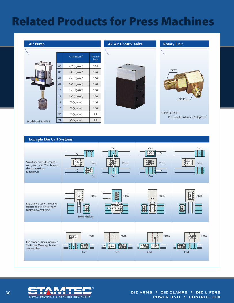
DIE ARMS • DIE CLAMPS • DIE LIFERSPOWER UNIT • CONTROL BOX
DIE ARMS • DIE CLAMPS • DIE LIFERSPOWER UNIT • CONTROL BOX
30 3
Automating the die changing process and providing increased speed, e�ciency and productivity.
• Die Arms • Die Clamps • Die Lifters • Power Unit • Control Box
Die Clamp Series Die Arm SeriesHMI ControlDie Lifter Series Power Unit
In addition, all dies can be changed without any modi�cation allowing for the use of standardized die and press equipment, SAVING COSTS.
Lastly, multiple presses can share a single Q. D. C. system, further economizing on costs and resulting in higher e�ciency and productivity.
Model on P12~P13
Example Die Cart Systems
Simultaneous 2-die change using two carts. The shortestdie change time is achieved.
Die change using a moving bolster and two stationary tables. Low cost type.
Die change using a powered2-die cart. Many applicationsare possible.
Cart
Press
Cart
Cart
Press
Cart Cart
Cart
Press PressA A B B
A A
A
B
Fixed Platform
Press Press
BA
Press
A
A B
BA
Press
PressA
B
Cart
Press
Cart
BA
Press
Cart Cart
BA
PressB
A
Air Pump AV Air Control Valve Rotary Unit
At Air 5kg/cm² PressureRatio
06 1:84
1:60
1:50
1:40
1:30
1:20
1:16
1:10
1:8
1:5
420 (kg/cm²)
300 (kg/cm²)
250 (kg/cm²)
200 (kg/cm²)
150 (kg/cm²)
100 (kg/cm²)
80 (kg/cm²)
50 (kg/cm²)
40 (kg/cm²)
26 (kg/cm²)
07
08
09
10
12
14
16
20
24
1/4"PT x 1/4"HPressure Resistance : 700kg/cm 2
1/4"PT
1/4"Hose
Related Products for Press Machines
METAL STAMPING & FORMING EQUIPMENT METAL STAMPING & FORMING EQUIPMENT

DIE ARMS • DIE CLAMPS • DIE LIFERSPOWER UNIT • CONTROL BOX
DIE ARMS • DIE CLAMPS • DIE LIFERSPOWER UNIT • CONTROL BOX
2 31
NotesQuick Die Change SystemAutomatic Die Changing System for Presses and Production Lines
Die Arm SeriesDie Lifter Series Power UnitDie Clamp Series Die Arm Series
STAMTEC Quick Die Change (Q. D. C.) systems automate the die changing process and provide increased speed, e�ciency and productivity. Q.D.C. systems not only reduce die change time, but promote diverse small batch production runs and streamline production management.
FEATURES• Decreased die change time• Designed for hydraulic and pneumatic presses• Increased efficiency• Reduced labor costs• Safer operations
Quick Die Change systems are becoming a standard for large manufacturers looking to increase production e�ciency, and improve overall working environments. Automated operations reduce labor expenses, but also reduce workshop accidents and the physical stresses on operators, making them more productive.
Date:
METAL STAMPING & FORMING EQUIPMENT METAL STAMPING & FORMING EQUIPMENT
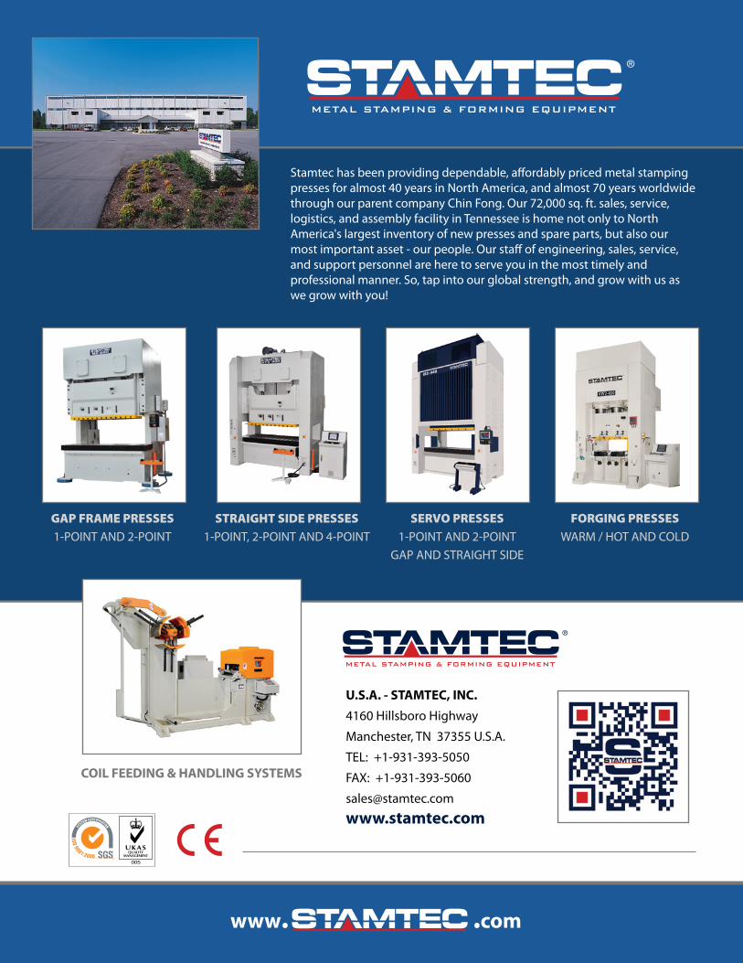
Stamtec has been providing dependable, a�ordably priced metal stamping presses for almost 40 years in North America, and almost 70 years worldwide through our parent company Chin Fong. Our 72,000 sq. ft. sales, service, logistics, and assembly facility in Tennessee is home not only to North America's largest inventory of new presses and spare parts, but also our most important asset - our people. Our sta� of engineering, sales, service, and support personnel are here to serve you in the most timely and professional manner. So, tap into our global strength, and grow with us as we grow with you!
METAL STAMPING & FORMING EQUIPMENT
FORGING PRESSESWARM / HOT AND COLD
SERVO PRESSES1-POINT AND 2-POINT
GAP AND STRAIGHT SIDE
STRAIGHT SIDE PRESSES1-POINT, 2-POINT AND 4-POINT
GAP FRAME PRESSES1-POINT AND 2-POINT
U.S.A. - STAMTEC, INC.
4160 Hillsboro Highway
Manchester, TN 37355 U.S.A.
TEL: +1-931-393-5050
FAX: +1-931-393-5060
www.stamtec.com
METAL STAMPING & FORMING EQUIPMENT
COIL FEEDING & HANDLING SYSTEMS
Quick Die Change SystemAutomatic Die Changing System for Presses and Production Lines
METAL STAMPING & FORMING EQUIPMENT
DIE ARMS • DIE CLAMPS • DIE LIFERS • POWER UNIT • CONTROL BOX