formulation of research problem- an approach …
TRANSCRIPT

1ACS College of Engineering, Department of Mechanical Engineering Mechanical Engineering
VISVESVARAYA TECHNOLOGICAL UNIVERSITY - BELAGAVI
Module 31.Tool Wear/Tool Life
2.Machine Time

2ACS College of Engineering, Department of Mechanical Engineering Mechanical Engineering
VISVESVARAYA TECHNOLOGICAL UNIVERSITY - BELAGAVI
Tool WearIntroduction to Tool Wear: Tool Wear is a term that describes the
gradual failure of a cutting tool due to its operation.
• A cutting tool is ground with various angles to perform cutting
operation efficiently & effectively on different materials & in
different situations of varying speed, depth & feed of cut
• Under regular operation, the tool wears out gradually leading to
changes in the angles ground on the cutting tool, which in turn
ceases to tool to function satisfactorily
• A very short tool life is not economical, as tool grinding & tool
replacement increases the cot of machining and in-turn increases the
cost of the product
• Tool wear cannot be avoided, but under suitable operating
conditions it can be minimized
3ACS College of Engineering, Department of Mechanical Engineering Mechanical Engineering
VISVESVARAYA TECHNOLOGICAL UNIVERSITY - BELAGAVI
• To study the wear mechanism and types of wear
• Understand about the factors affecting tool life and
Taylor’s tool life equation
• To study the machinability and machinability index
• To know about the Economics of machining process and
the factors affecting it
Objectives of Tool Wear

4ACS College of Engineering, Department of Mechanical Engineering Mechanical Engineering
VISVESVARAYA TECHNOLOGICAL UNIVERSITY - BELAGAVI
a) high localized stresses at the tip of the tool
b) high temperatures, especially along the rake face
c) sliding of the chip along the rake face
d) sliding of the tool along the newly cut workpiece surface
These condition leads to Tool Wear:
These conditions induce tool wear, which is a major consideration in
all machining operations. Tool wear adversely affects tool life, the
quality of the machined surface and its dimensional accuracy, and,
consequently, the economics of cutting operations. Wear is a gradual
process. The rate of tool wear depends on tool and workpiece
materials, tool geometry, process parameters such as speed, feed and
depth of cut, cutting fluids, and the characteristics of the machine tool.
Conditions of Cutting Tool

5ACS College of Engineering, Department of Mechanical Engineering Mechanical Engineering
VISVESVARAYA TECHNOLOGICAL UNIVERSITY - BELAGAVI
There are 3 possible ways a cutting tool can fail in
machining:
• Fracture Failure: This mode of failure occurs when the cutting
force at the tool point becomes excessive, causing it to fail suddenly
by brittle fracture (Mechanical Chipping)
• Temperature Failure: This failure occurs when the cutting
temperature is too high for the tool material, causing the material at
the tool point to soften, which leads to plastic deformation and loss
of the sharp edge
• Gradual Wear: Gradual wearing of the cutting edge causes loss of
tool shape, reduction in cutting efficiency, an acceleration of
wearing as the tool becomes heavily worn, and finally tool failure in
a manner similar to a temperature failure
Modes of Tool Wear

6ACS College of Engineering, Department of Mechanical Engineering Mechanical Engineering
VISVESVARAYA TECHNOLOGICAL UNIVERSITY - BELAGAVI
Modes of Tool Wear
Fracture Wear
Temperature Wear
7ACS College of Engineering, Department of Mechanical Engineering Mechanical Engineering
VISVESVARAYA TECHNOLOGICAL UNIVERSITY - BELAGAVI
Gradual Wear/Tool Wear can be classified into:
• Crater Wear: It consists of a cavity in the rake face of the tool
that forms and grows from the action of the chip sliding against the
surface. High stresses and temperatures characterize the tool–chip
contact interface, contributing to the wearing action. The crater can
be measured either by its depth or its area
• Flank Wear: Flank wear occurs on the relief (flank) face of the tool.
It generally is attributed to rubbing of the tool along the machined
surface, thereby causing adhesive or abrasive wear and high
temperatures, which adversely affect tool-material properties
Tool Wear/Gradual Wear

8ACS College of Engineering, Department of Mechanical Engineering Mechanical Engineering
VISVESVARAYA TECHNOLOGICAL UNIVERSITY - BELAGAVI
Tool Wear/Gradual Wear
Crater Wear
Flank Wear

9ACS College of Engineering, Department of Mechanical Engineering Mechanical Engineering
VISVESVARAYA TECHNOLOGICAL UNIVERSITY - BELAGAVI
• Abrasion. This is a mechanical wearing action caused by hard particles in the work
material gouging and removing small portions of the tool. This abrasive action
occurs in both flank wear and crater wear; it is a significant cause of flank wear.
• Adhesion. When two metals are forced into contact under high pressure and
temperature, adhesion or welding occur between them. These conditions are present
between the chip and the rake face of the tool. As the chip flows across the tool,
small particles of the tool are broken away from the surface, resulting in attrition of
the surface.
• Diffusion: This is a process in which an exchange of atoms takes place across a
close contact boundary between two materials. In the case of tool wear, diffusion
occurs at the tool–chip boundary, causing the tool surface to become depleted of the
atoms responsible for its hardness. As this process continues, the tool surface
becomes more susceptible to abrasion and adhesion. Diffusion is believed to be a
principal mechanism of crater wear.
• Oxidation/Corrosion: Oxidation is the result of a chemical reaction b/w the tool
surface & surrounding oxygen at high temperatures. During metal cutting, the high
temperatures generated at the tool-work interface causes oxidation of carbide in the
cutting tool, forming a layer on tool surface. This layer is removed during
,machining process by abrasion, another layer is formed and it repeats
Tool Wear Mechanism

10ACS College of Engineering, Department of Mechanical Engineering Mechanical Engineering
VISVESVARAYA TECHNOLOGICAL UNIVERSITY - BELAGAVI
Tool life is the time duration a tool can be reliably used for cutting
before it must be discarded or re-ground. The life of the cutting tool is
one of the most important economic considerations in metal cutting.
Hence the tool must be utilized efficiently to the maximum possible
extent before it can be ground or discarded, because tool grinding or
replacement costs are very high. The life of the tool is affected by
various parameters.
Tool Life

11ACS College of Engineering, Department of Mechanical Engineering Mechanical Engineering
VISVESVARAYA TECHNOLOGICAL UNIVERSITY - BELAGAVI
• Cutting speed: Cutting speed has the greatest influence on tool life.
As the cutting speed increases the temperature also rises. The heat is
more concentrated on the tool than on the work and the hardness of
the cutting tool changes so the relative increase in the hardness of
the work accelerates the abrasive action. The criterion of the wear is
dependent on the cutting speed because the predominant wear may
be wear for flank or crater if cutting speed is increased.
• Feed and depth of cut: The tool life is influenced by the feed rate
also. With a fine feed the area of chip passing over the tool face is
greater than that of coarse feed for a given volume of metal removal.
• Tool Geometry: The tool life is also affected by tool geometry. A
tool with large rake angle becomes weak as a large rake reduces the
tool cross-section and the amount of metal to absorb the heat.
Parameters affecting Tool Wear
12ACS College of Engineering, Department of Mechanical Engineering Mechanical Engineering
VISVESVARAYA TECHNOLOGICAL UNIVERSITY - BELAGAVI
• Tool material: Physical and chemical properties of work material
influence tool life by affecting form stability and rate of wear of
tool.
• Cutting fluid: It reduces the coefficient of friction at the chip tool
interface and increases tool life.
• Type of workpiece material: work pieces with greater hardness
require greater cutting forces leading to greater power consumption,
tool wear increases with greater forces thereby reducing the life of
cutting tool. Ductile materials deform easily, and low cutting forces
are needed, thus tool wear reduces
• Nature of cutting: Tool life is more in case of continuous cutting
when compared to intermitted type of cutting where the cutting edge
of the tool will not be in continuous contact with the work surface,
intermittent cutting causes regular impacts on the tool resulting in
failure of tool in short span. It must be ensured through all means to
have continuous type of cutting in order to enhance tool life

13ACS College of Engineering, Department of Mechanical Engineering Mechanical Engineering
VISVESVARAYA TECHNOLOGICAL UNIVERSITY - BELAGAVI
As cutting proceeds, the various wear mechanisms result in increasinglevels of wear on the cutting tool. The general relationship of toolwear versus cutting time is shown in Figure Although the relationshipshown is for flank wear, a similar relationship occurs for crater wear.Three regions can usually be identified in the typical wear growthcurve. The first is the breaking period, in which the sharp cutting edgewears rapidly at the beginning of its use. This first region occurs withinthe first few minutes of cutting. The break-in period is followed bywear that occurs at a fairly uniform rate. This is called the steady-statewear region. In our figure, this region is pictured as a linear function oftime, although there are deviations from the straight line in actualmachining. Finally, wear reaches a level at which the wear rate beginsto accelerate. This marks the beginning of the failure region, in whichcutting temperatures are higher, and the general efficiency of themachining process is reduced. If allowed to continue, the tool finallyfails by temperature failure
Tool Wear v/s Cutting Time

14ACS College of Engineering, Department of Mechanical Engineering Mechanical Engineering
VISVESVARAYA TECHNOLOGICAL UNIVERSITY - BELAGAVI
Tool Wear v/s Cutting Time
Tool Wear v/s Cutting Time

15ACS College of Engineering, Department of Mechanical Engineering Mechanical Engineering
VISVESVARAYA TECHNOLOGICAL UNIVERSITY - BELAGAVI
• Cutting speed forms the most important parameter of all the variables (feed, depth
of cut, type of work material, coolant, etc.,), that affects the tool life
• F. W. Taylor, an American engineer developed a standard test to determine the
relationship b/w cutting speed & time the tool remains useful
• Test has been carried out for different combination of tool workpiece material; and
the flank wear of the tool under test has been measured
• It has been found that a practical amount of wear to measure before breakage was
0.75 mm (VB) for solid & brazed tips, and 1.25 mm (VB) for ceramic tools
• Tests have been carried out to determine the time taken to reach this amount of
wear at different cutting speeds
• The results have been plotted on a graph showing that a logarithmic relationship
existed b/w the cutting speed & the tool life (cutting time) an empirical relation
for tool life with cutting speed has been given by Taylor & is known as Taylor’s
tool life equation
VT n=C
where V = cutting speed, m/min (ft/min); T = tool life in min; and n and C are
parameters whose values depend on feed, depth of cut, work material, tooling
(material in particular), and the tool life criterion used.
Tayler’s Tool Life Equation

16ACS College of Engineering, Department of Mechanical Engineering Mechanical Engineering
VISVESVARAYA TECHNOLOGICAL UNIVERSITY - BELAGAVI
Tayler’s Tool Life Equation

17ACS College of Engineering, Department of Mechanical Engineering Mechanical Engineering
VISVESVARAYA TECHNOLOGICAL UNIVERSITY - BELAGAVI
• The value of index ‘n’ for most combinations of tool & workpiece
material can be found in a tabular form in good machining hand
books
• Table shows the range of values of ‘n’ for different combinations of
tool-workpieces materials
• The value of ‘n’ increases with increase in the refractoriness of the
tool material
Tayler’s Tool Life Equation
SlNo.
Tool Material Value of ‘n’
1 HSS Tool 0.1-0.18
2 Uncoated Tungsten carbide (WC) 0.2-0.25
3 Ti-C or Ti-N Coated WC tools 0.3
4 Al2O3 Coated WC tools 0.4
5 Ceramic Tools 0.4-0.7

18ACS College of Engineering, Department of Mechanical Engineering Mechanical Engineering
VISVESVARAYA TECHNOLOGICAL UNIVERSITY - BELAGAVI
Cutting Speed: Cutting speed refers to the relative surface
speed b/w the tool & the workpiece. The life of the tool
varies inversely as the cutting speed. As the cutting speed is
increases, wear rate increases, so same wear criterion is
reached in less time, i.e., tool life decreases with increasing
cutting speeds as shown in figure. The relation b/w the
cutting speed (V) and tool life (T) is given by Taylor’s
equation in the form VT n=C, where ‘n; is the exponential
term and ‘C’ the machining constant.
Effect of Cutting Parameters on
Tool Life

19ACS College of Engineering, Department of Mechanical Engineering Mechanical Engineering
VISVESVARAYA TECHNOLOGICAL UNIVERSITY - BELAGAVI
Effect of Cutting Parameters on
Tool Life
VT n=C VT n=C
Effect of Speed on Tool Life

20ACS College of Engineering, Department of Mechanical Engineering Mechanical Engineering
VISVESVARAYA TECHNOLOGICAL UNIVERSITY - BELAGAVI
Feed: Feed is the amount of material removed for each revolution, or
per-pass of the tool over the workpiece. Increasing feed rate increases
cutting temperature and flank wear thereby shortening the life of
cutting tool. However, effect on the tool life is minimal when compared
to cutting speed. The rate of feed given depends on the depth of cut.
Depth of cut: Depth of cut relates to the depth of cutting edge of the
tool engages the work. Small depths of cuts result in friction when
cutting hardened layer of work metal. Increasing the depth of cut will
increase the tool life over an increase in feed rate. But, as long as it is
practical & chip formation is satisfactory, it is better to choose a heavy
feed rate. Deeper cut is more advantageous than a heavy feed,
especially where longer tool life is needed.
Effect of Cutting Parameters on
Tool Life

21ACS College of Engineering, Department of Mechanical Engineering Mechanical Engineering
VISVESVARAYA TECHNOLOGICAL UNIVERSITY - BELAGAVI
• The relationship b/w various parameters is given by the equation:
𝑉 =257
𝑇0.19𝑓0.36𝑡0.8m/min
Where V = cutting speed in m/min, T = Tool life in minutes, f = feed in
mm/min, t = depth of cut in mm.
For a give tool life, the relationship among the other variables as:
𝑉 =𝐶
𝑓𝑎𝑡𝑏,
where C = machining constant and ‘a’ & ‘b’ are indices depending on
mechanical properties of workpiece material.
Effect of Cutting Parameters on
Tool Life

22ACS College of Engineering, Department of Mechanical Engineering Mechanical Engineering
VISVESVARAYA TECHNOLOGICAL UNIVERSITY - BELAGAVI
Machinability is a term that describes the ease with which a
material can be cut with a satisfactory surface finish, long
tool life, low force & power requirements and with low cost.
For example, low alloyed carbon steel is easier to cut
compared to austenitic stainless steels. Hence, the low alloy
carbon steel is said to have a comparatively better
machinability.
Machinability
23ACS College of Engineering, Department of Mechanical Engineering Mechanical Engineering
VISVESVARAYA TECHNOLOGICAL UNIVERSITY - BELAGAVI
• Physical properties of work material, like tensile strength, hardness, etc., the more
the strength & hardness of the work material, the more difficult it is to cut
• Chemical composition of work material. For example, the higher the carbon
content in steel, the more difficult it is to cut. In alloy steels, the presence of
elements like chromium, nickel, molybdenum & vanadium, etc., can cause
decreased machinability. On the other hand, addition of lead & sulphur improves
machinability
• Microstructure of work material. For example, variation in the arrangement of
atoms of work material, heat treatment of metals may change crystal structure
which affects machinability
• Cutting conditions like tool geometry, use of cutting fluid, selecting proper speed,
feed & depth of cut affects machinability
• Rigidity of tool & work holding devices indirectly affects machinability. If not
secured rigidly, vibrations may develop causing the tool to have intermittent
cutting instead of continuous cutting resulting in decrease in the life of the cutting
tool.
Factors on which Machinability
Depends
24ACS College of Engineering, Department of Mechanical Engineering Mechanical Engineering
VISVESVARAYA TECHNOLOGICAL UNIVERSITY - BELAGAVI
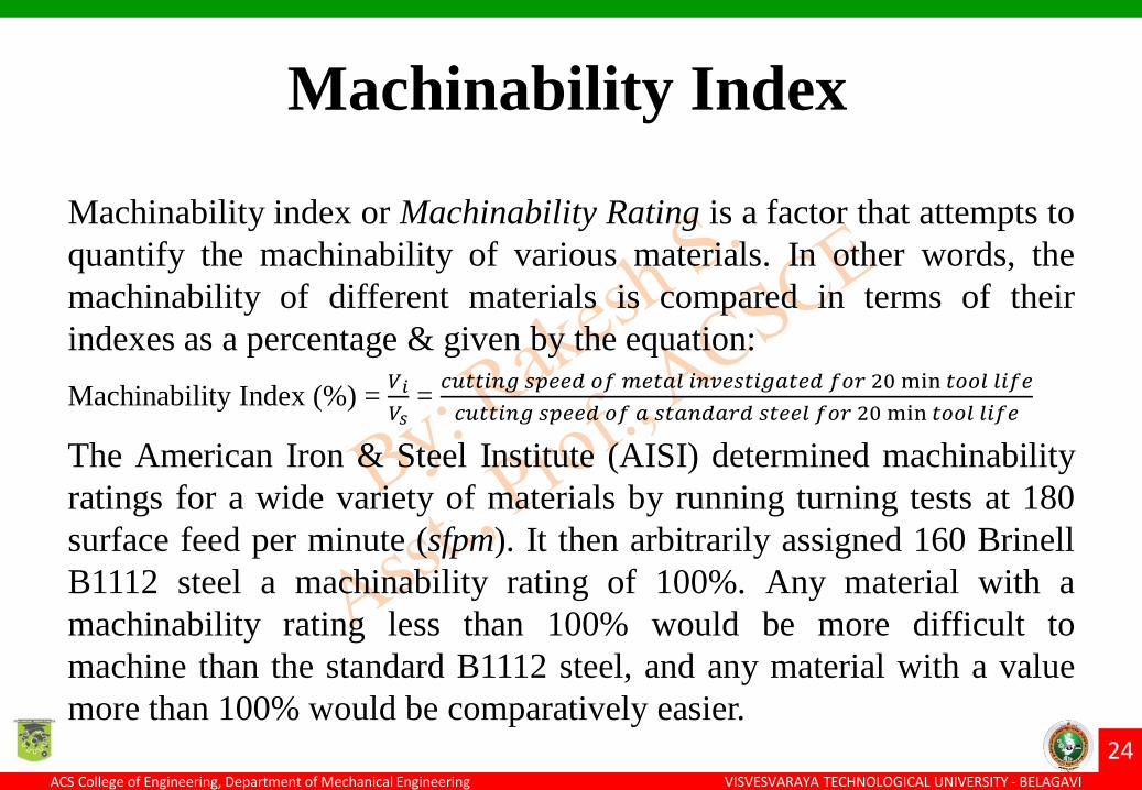
Machinability index or Machinability Rating is a factor that attempts to
quantify the machinability of various materials. In other words, the
machinability of different materials is compared in terms of their
indexes as a percentage & given by the equation:
Machinability Index (%) =𝑉𝑖
𝑉𝑠=𝑐𝑢𝑡𝑡𝑖𝑛𝑔 𝑠𝑝𝑒𝑒𝑑 𝑜𝑓 𝑚𝑒𝑡𝑎𝑙 𝑖𝑛𝑣𝑒𝑠𝑡𝑖𝑔𝑎𝑡𝑒𝑑 𝑓𝑜𝑟 20 min 𝑡𝑜𝑜𝑙 𝑙𝑖𝑓𝑒
𝑐𝑢𝑡𝑡𝑖𝑛𝑔 𝑠𝑝𝑒𝑒𝑑 𝑜𝑓 𝑎 𝑠𝑡𝑎𝑛𝑑𝑎𝑟𝑑 𝑠𝑡𝑒𝑒𝑙 𝑓𝑜𝑟 20 min 𝑡𝑜𝑜𝑙 𝑙𝑖𝑓𝑒
The American Iron & Steel Institute (AISI) determined machinability
ratings for a wide variety of materials by running turning tests at 180
surface feed per minute (sfpm). It then arbitrarily assigned 160 Brinell
B1112 steel a machinability rating of 100%. Any material with a
machinability rating less than 100% would be more difficult to
machine than the standard B1112 steel, and any material with a value
more than 100% would be comparatively easier.
Machinability Index

25ACS College of Engineering, Department of Mechanical Engineering Mechanical Engineering
VISVESVARAYA TECHNOLOGICAL UNIVERSITY - BELAGAVIACS College of Engineering, Department of Mechanical EngineeringMechanical Engineering
25VISVESVARAYA TECHNOLOGICAL UNIVERSITY - BELAGAVI

26ACS College of Engineering, Department of Mechanical Engineering Mechanical Engineering
VISVESVARAYA TECHNOLOGICAL UNIVERSITY - BELAGAVI
• During metal cutting, as the cutting tool slides in the workpiece
material, heat is generated due to the friction b/w the tool &
workpiece material
• Also, as chip slides up the tool face, heat is generated due to friction
at the contact points b/w the chip & tool-face
• The excessive heat thus generated can damage the microstructure of
both the cutting tool & the workpiece
• Also, the life of the cutting tool reduces at higher temperatures
• In order to reduce friction or heat generated, cutting fluids are used
• A cutting fluid or coolant is a liquid, added to the cutting zone, in
order to reduce the effects of friction b/w the tool-work & tool-chip
interface by way of cooling & lubrication
Cutting Fluids

27ACS College of Engineering, Department of Mechanical Engineering Mechanical Engineering
VISVESVARAYA TECHNOLOGICAL UNIVERSITY - BELAGAVI
• Controls the temperature at the cutting zone through cooling &
lubrication, which in turn helps in decreasing tool wear & extending
tool life
• Cooling & lubricating action of cutting fluid helps in achieving the
desired size, shape & finish of the workpiece. The removal of heat
by cutting fluid prevents the workpiece from expanding during the
machining operation, which would other wise cause size variations
as well as damage to the microstructure. Also, proper use of coolants
can make higher metal removal rates possible
• Cutting fluid helps to flush away chips & metal fines from the
cutting zone thereby preventing the tool & the finish of the work
surface from becoming marred & occurrence of built-up-edge
Functions of Cutting Fluids

28ACS College of Engineering, Department of Mechanical Engineering Mechanical Engineering
VISVESVARAYA TECHNOLOGICAL UNIVERSITY - BELAGAVI
• High specific heat & High Thermal Conductivity, so that maximum heat will be
absorbed & removed per unit of fluid volume circulated
• Good lubricating property, so that a strong protective film b/w the tool face & the
workpiece metal can exist. Such a film assists the chip in sliding easily over tool
face. Besides reducing heat, a good lubricating fluid lower power consumption &
reduces the rate of tool wear, particularly in machining tough & ductile metals
• Non-Corrosive, in order to avoid damage to the workpiece & the m/c parts
• Non-Toxic & Odorless, in order to provide better working conditions to human
operators
• A cutting fluid should have high flash point to avoid problems associated with
heat damage, production of smoke, or fluid ignition
• Low Viscosity, far easy circulation. Low viscosity fluids also allow grit & dirt to
settle out of suspension & helps for easy re-circulation through the machining
system
• Highly stable, in order to resist its decomposition during its storage & use
• In some operations, fluid transparency may be a desired characteristics for a
cutting fluid. Transparent fluids allow operators to see the work area more clearly
during machining operations
Properties of Cutting Fluids

29ACS College of Engineering, Department of Mechanical Engineering Mechanical Engineering
VISVESVARAYA TECHNOLOGICAL UNIVERSITY - BELAGAVI
• Oil-based fluids
– Straight oils
– Soluble oils
• Chemical fluids
– Synthetic oils
– Semi-Synthetic oils
Types of Cutting Fluids

30ACS College of Engineering, Department of Mechanical Engineering Mechanical Engineering
VISVESVARAYA TECHNOLOGICAL UNIVERSITY - BELAGAVI
Oil-based fluids consist of a diverse range of oil mixture with various
additives & compounds to give the required properties to the cutting
fluids. Oil-based fluids include straight oil & soluble oils.
Straight Oils:
Straight Cutting Oils (or Neat Oils) are so called because they do not
contain water. The cutting fluid is composed of 100% petroleum oil or
mineral oil along with some lubricants such as fats, vegetable oil &
esters, as well as extreme pressure (EP) additives in order to improve
specific properties. Generally, additives are not required for light duty
machining operations, however, for severe machining operation, where
heavy cuts are to be taken, and machining hard materials like titanium,
stainless steel etc., EP additives such as sulfur, chlorine or phosphorous
compounds are often used. These additives improve the lubricating &
wettability property; that is, the ability of the oil to coat the cutting
tool, workpiece & the chips.
Oil-Based Cutting Fluids

31ACS College of Engineering, Department of Mechanical Engineering Mechanical Engineering
VISVESVARAYA TECHNOLOGICAL UNIVERSITY - BELAGAVI
Advantages:
• Provides excellent lubricating property b/w the workpiece & cutting
tool
• Tool life can be increased
• Good rust protection
• Absence of water eliminates bacterial development & odour
problems
Disadvantages:
• Costlier
• Poor heat dissipating properties
• Increased fire risk, and hence its use is limited to low-temperature &
low-pressure operations
Straight Oils

32ACS College of Engineering, Department of Mechanical Engineering Mechanical Engineering
VISVESVARAYA TECHNOLOGICAL UNIVERSITY - BELAGAVI
Soluble Oils, also referred as Emulsions, emulsifiable oils or water-soluble oils, are
generally comprised of 60%-90% petroleum or mineral oil, emulsifiers and other
extreme pressure (EP) additives. Use of soluble oils for a particular application
depends on the concentration of water & oil. Lean concentrations containing more
water & less oil provide better cooling, but less lubrication. On the other hand, rich
concentrations containing less water & more oil provide better lubrication qualities,
but poor cooling.
Advantages:
• Good lubrication capability
• Suitable for light & medium duty operations involving both ferrous & non-ferrous
metals
• Concentration of oil can be varied for heavy-duty applications
• Least expensive among all the cutting fluids
Disadvantages:
• Presence of water makes the oil more susceptible to corrosion, bacterial growth &
odourness
• Maintenance cost to retain the desired properties of the oil is relatively high
• Not suitable for high tensile or stainless steel alloys
Soluble Oils
Applications: Soluble oil is suitable for general purpose cutting
operations on low & medium tensile steels, free machining of brass
bronze & cast iron. It may also be used as a grinding fluid in non-critical
applications, however it is not suitable for high tensile or stainless steel
or nickel alloys.

33ACS College of Engineering, Department of Mechanical Engineering Mechanical Engineering
VISVESVARAYA TECHNOLOGICAL UNIVERSITY - BELAGAVI
Chemical cutting fluids contain little or no oil with pre-
concentrated emulsions on low & medium tensile steels, free
machining of brass bronze & cast Iron. It may be used as a
grinding fluid in non-critical applications, however it is not
suitable for high tensile or stainless steel or nickel alloys.
Chemical Cutting Fluids
34ACS College of Engineering, Department of Mechanical Engineering Mechanical Engineering
VISVESVARAYA TECHNOLOGICAL UNIVERSITY - BELAGAVI
Synthetic oils generally consist of chemical lubricants & rust
inhibitors dissolved in water. Emulsifiers can be added to create
lubrication properties similar to soluble oils, allowing the fluid to act as
a lubricant & coolant in heavy duty machining operations. The various
synthetic chemicals found in this type of oil include:
a) Amines & nitrates for rust prevention
b) Phosphates & Borates for water softening
c) Soaps & wetting agents for lubrication
d) Glycols to act as blending agents
e) Biocides to control bacterial growth
Synthetic Oils

35ACS College of Engineering, Department of Mechanical Engineering Mechanical Engineering
VISVESVARAYA TECHNOLOGICAL UNIVERSITY - BELAGAVI
Advantages:
• Good corrosion control
• Superior cooling properties
• Greater stability when mixed with hard water
• Can be stored for long periods of time without any problems
• Easy maintenance
Disadvantages:
• Synthetic coolants have a tendency to foam. If the rate of coolant flow fro
a particular application is high, excessive foaming can be caused, resulting
in poor surface finish & reduced tool life
• Lubricating property is not satisfactory
• Ingredients added to enhance the lubricating property can result in
component rusting & leave gummy residues on the m/c system
• Synthetic fluids are easily contaminated by other m/c fluids like
lubricating oils, & hence need to be monitored & maintained so that it can
be used effectively
Synthetic Oils
Application: Used in grinding carbide tools with diamond wheels, ordinary
commercial grinding where finish is not very critical, in some CNC machines
where stock removal is low etc.,

36ACS College of Engineering, Department of Mechanical Engineering Mechanical Engineering
VISVESVARAYA TECHNOLOGICAL UNIVERSITY - BELAGAVI
Semi-synthetic oils, also referred to as semi-chemical fluids are a
combination of mineral oil in small amounts varying from 20%-30% in
a water-dilatable concentration & certain synthetic chemicals. The
synthetic chemicals consists mainly emulsifiers & water; wetting
agents, corrosion inhibitors & biocide additives. Since this type of oil
includes both constituents of synthetic & soluble oils, they possess
properties common to both the types of oils.
Semi-Synthetic Oils
Advantages Disadvantages
Better cooling & wettability properties Water hardness affectsthe stability of semi-synthetic oilsCan be used for heavy-duty operation
Generates less smoke & provides better controlover bacterial growth. Oil can thus be stored forappreciable length of time
Lubricating property isnot satisfactory
Lower viscosity of oil helps easy recirculation of thefluid
Good corrosion protection They easily foam

37ACS College of Engineering, Department of Mechanical Engineering Mechanical Engineering
VISVESVARAYA TECHNOLOGICAL UNIVERSITY - BELAGAVI
• Cutting speed, feed & depth of cut selected
• Type, hardness & microstructure of the workpiece material being
machined
• Operating temperature range
• Cost & life expectancy of fluid
• Fluid compatibility with workpiece & machine components
• Ease of storage & handling while in use
• Ease of fluid recycling or disposal
• Shelf-life required
Selection of cutting fluids

38ACS College of Engineering, Department of Mechanical Engineering Mechanical Engineering
VISVESVARAYA TECHNOLOGICAL UNIVERSITY - BELAGAVI
Apart from selecting the right cutting fluid, it is also important to
choose a proper method of circulating the fluid to the cutting zone. The
principal methods of applying the cutting fluid include:
• Flood Application of Fluids: A flood of cutting fluid is delivered to
the cutting zone by means of a pipe, hose or nozzle system
• Jet Application of Fluid: A jet of cutting fluid is directed to the
cutting zone
• Mist (spray) Application of Fluid: The cutting fluid is atomized by
a jet of air, & the mist is directed to the cutting zone
In certain machining operations like drilling deep holes, or machining
ultra-tough materials, it is very difficult to circulate the cutting fluid
into the cutting zone. In such cases, the cutting fluid is supplied
through the tool by drilling small holes in the tool.
Methods of Cutting Fluids

39ACS College of Engineering, Department of Mechanical Engineering Mechanical Engineering
VISVESVARAYA TECHNOLOGICAL UNIVERSITY - BELAGAVI
Introduction to Surface Finish:
Machining processes generate a wide variety of irregularities on the surface of the
workpiece. These irregularities are in the form of finely spaced markings (patterns)
left by the cutting tool on the workpiece surface. In simple words, the finish obtained
on the workpiece after machining is not perfectly smooth. The term surface finish, or
texture or surface roughness is used to indicate the local deviations of a work surface
from the perfectly flat ideal face (a true plane). The nature of surface is defined by
three characteristics as listed below & illustrated in figure.
1. Roughness – small, finely spaced surface irregularities (micro irregularities)
2. Waviness – surface irregularities of greater spacing (macro irregularities)
3. Lay – predominant direction of surface pattern
It is important to note that, no surface is perfectly smooth. All surfaces contain
irregularities to some extent. In machining operations, each kind of cutting tool leaves
its own individual markings (pattern) on the workpiece surface, and as such by
altering the parameters of the machining process, the pattern can be changed.
Surface Finish

40ACS College of Engineering, Department of Mechanical Engineering Mechanical Engineering
VISVESVARAYA TECHNOLOGICAL UNIVERSITY - BELAGAVI
Surface Finish

41ACS College of Engineering, Department of Mechanical Engineering Mechanical Engineering
VISVESVARAYA TECHNOLOGICAL UNIVERSITY - BELAGAVI
Cutting Speed:
• Low cutting speed tends to form BUE on the rake face of the cutting tool, causing
the tool edge to become blunt & thereby producing a rough surface on the work
parts, friction also increases thus increases power consumption
• Increasing cutting speed improves surface finish due to continuous reduction in
formation of BUE, this due to rise in tool temperature & decrease in frictional
forces
Feed:
• Increasing feed rate during machining deteriorates surface finish, higher
irregularities are formed with higher feed rates
• Slow feed rates give good surface finish, however upto a certain value, &
thereafter the surface finish deteriorates, hence a proper feed rate is tio be selected
based on the depth of cut
Effect of Machining parameters on
Surface Finish

42ACS College of Engineering, Department of Mechanical Engineering Mechanical Engineering
VISVESVARAYA TECHNOLOGICAL UNIVERSITY - BELAGAVI
Effect of Machining parameters on
Surface FinishDepth of Cut:
• Increasing the depth of cut during machining process deteriorates surface finish
• High depth of cut implies higher cutting forces, leading to crater & vibrations in
m/c tool that impacts the surface finish
• Increasing depth of cut tends to increase waviness height, as a general thumb rule,
the depth of cut should be slightly higher than the nose radius of the cutting tool
edge
Other parameters influencing surface finish:
1. Tool geometry – nose radius, rake angle, relief angle, side cutting angle &
cutting edge
2. Mechanical properties of tool & work materials
3. Type of cutting fluid used
4. m/c tool rigidity & accuracy

43ACS College of Engineering, Department of Mechanical Engineering Mechanical Engineering
VISVESVARAYA TECHNOLOGICAL UNIVERSITY - BELAGAVI
• The ultimate goal of any machining process is to produce a work
part of desired shape, size & finish with low cost & minimum time
duration
• These two qualities, which from the primary interest in all
machining processes depends on various parameters like speed,
feed, depth of cut, tool material, cutting fluid, etc., thereby making
an exact economic analysis extremely complicated
• In mass scale production, often one or two operations are performed
on a single m/c, and as such, preliminary analysis can be carried out
to provide some basic information on the important economic
aspects of the machining operation
• Such an analysis can help in choosing optimum cutting conditions
apart from allocating human labour & m/c’s to perform at an
optimum level thereby achieving the economic goal of highest
return with minimum investment
Economics of Machining Process

44ACS College of Engineering, Department of Mechanical Engineering Mechanical Engineering
VISVESVARAYA TECHNOLOGICAL UNIVERSITY - BELAGAVI
Choice of Cutting Speed
Economic choice for cutting speed

45ACS College of Engineering, Department of Mechanical Engineering Mechanical Engineering
VISVESVARAYA TECHNOLOGICAL UNIVERSITY - BELAGAVI
For max production rate, the speed that minimizes machining time per unit part is
selected, while for minimum cost per unit, the cutting speed that minimizes
production cost per part is to be selected. However both requirements cannot be
achieved for a single cutting speed. Figure illustrates the relationship b/w cutting
speed, production time (rate) & production cost. From figure ‘a’, it is clear that the
production rate (no. of pieces produced per unit time) gradually increases with
increase in cutting speed up to point ‘Pm’ however with further increase in speed, the
production rate decreases. This is due to the fact that increasing speeds raises cutting
temperature, causing tool wear. Hence time is lost for tool sharpening or tool change
leading to decrease in production rate. The corresponding speed at maximum
production ‘Pm’ is the optimum cutting speed ‘Vm’. This speed is the optimum value
at which the total time taken in production of the component will be minimum.
However, our interest in economic analysis is not satisfied yet, because the goal lies
in producing the components at maximum rate & at minimum cost.
Figure ‘b’ illustrates the variation of speed w.r.t., cost per piece produced. It is clear
from the plot that the cutting speed ‘Vc’ at which the production cost ‘Pc’ is minimum
is different from the cutting speed ‘Vm’ at which the production rate ‘Pm’ is
maximum. The region lying b/w these two cutting speeds is known as high efficiency
rage (Hi-E) & any speeds lying in this range are either economical or more
productive.
Choice of Cutting Speed

46ACS College of Engineering, Department of Mechanical Engineering Mechanical Engineering
VISVESVARAYA TECHNOLOGICAL UNIVERSITY - BELAGAVI
Choice of Cutting Speed
Relation for cutting speed for minimum cost & maximum production

47ACS College of Engineering, Department of Mechanical Engineering Mechanical Engineering
VISVESVARAYA TECHNOLOGICAL UNIVERSITY - BELAGAVI
• The choice of feed for economic machining depends on the type of operation: i.e.,
roughness or finishing operation
• When a finishing cut is to be taken, the choice of appropriate feed depends on the
dimensional accuracy & surface finish required
• In such a case, the choice of feed is in the hands of the design engineer who has
specified the surface finish requirement for the component to be produced
• However in roughing operations, the primary objective is to remove material as
much as possible from the workpiece material within minimum possible time
duration
• It is well known that equal changes in speed & feed affects the tool temperature
by the same amount
• Further, an increase in feed will not affect the relative speed of sliding at the
wearing function of both temperature & relative speed of sliding, it is
advantageous to have a greater feed than cutting speed from a certain limit due to
increase in tool forces during machining
• The limiting value of feed depends on maximum tool force the machine is capable
of withstanding
Choice of Feed

48ACS College of Engineering, Department of Mechanical Engineering Mechanical Engineering
VISVESVARAYA TECHNOLOGICAL UNIVERSITY - BELAGAVI
For minimum production cost, the life of cutting tool must extend for
longer periods. This can be achieved with minimum cutting speed,
because, as the cutting speed increases, tool wear also increases. The
tool life that corresponds to minimum cutting speed for minimum cost
can be calculated using Taylor’s tool life equation:
VTn=C,
where V = Vc = Cutting speed for minimum cost,
T = Tool Life, C & n or Taylor’s constants
Tool Life for Minimum Cost (Tmin)

49ACS College of Engineering, Department of Mechanical Engineering Mechanical Engineering
VISVESVARAYA TECHNOLOGICAL UNIVERSITY - BELAGAVI
The tool life for minimum production time or maximum production
rate is a function of the index ‘n’ as described in Taylor’s tool life
equation. The equation is of the form as follows:
𝑇𝑚𝑎𝑥 = [1
𝑛− 1]𝑇𝑐
𝑇𝑐= tool changing Time
𝑇𝑚𝑎𝑥= can be calculated using Taylor’s equation: VTn=C, where V =
Vm = Cutting speed for maximum production
Tool Life for Minimum Production time
(Tmin) or Maximum Production Rate (Tmax)

50ACS College of Engineering, Department of Mechanical Engineering Mechanical Engineering
VISVESVARAYA TECHNOLOGICAL UNIVERSITY - BELAGAVI
The equations discussed w.r.t., the cutting speed & tool life for
minimum cost & maximum production do not throw any light w.r.t.,
maximizing the profit rate. The maximize profit rate depends on the
rate of production & on the margin b/w the selling price & cost or
production. For example, to achieve minimum cost, the cutting speed
has to be minimum, however the production rate may be too low to
maximize the profit rate. Thus the cutting speed for maximum
efficiency (Vmp) would be different from that for minimum cost &
maximum production rate.
Tool Life for Maximum Efficiency
(Maximum Profit Rate)

51ACS College of Engineering, Department of Mechanical Engineering Mechanical Engineering
VISVESVARAYA TECHNOLOGICAL UNIVERSITY - BELAGAVI
Tool Life for Maximum Efficiency
(Maximum Profit Rate)
Tool Life for Max Efficiency [Max Profit Rate]

52ACS College of Engineering, Department of Mechanical Engineering Mechanical Engineering
VISVESVARAYA TECHNOLOGICAL UNIVERSITY - BELAGAVI
THANK YOU