formulation effects on the lubricity of o/w emulsions used
TRANSCRIPT
Formulation effects on the lubricity of o/w emulsions used asoil well working fluidsCitation for published version (APA):González, J. M., Quintero, F., Márquez, R. L., Rosales, S. D., & Quercia Bianchi, G. (2011). Formulation effectson the lubricity of o/w emulsions used as oil well working fluids. In G. Biresaw, & K. L. Mittal (Eds.), Surfactantsin Tribology (Vol. 2, pp. 241-265). CRC Press. https://doi.org/10.1201/b10868-14
DOI:10.1201/b10868-14
Document status and date:Published: 01/01/2011
Document Version:Publisher’s PDF, also known as Version of Record (includes final page, issue and volume numbers)
Please check the document version of this publication:
• A submitted manuscript is the version of the article upon submission and before peer-review. There can beimportant differences between the submitted version and the official published version of record. Peopleinterested in the research are advised to contact the author for the final version of the publication, or visit theDOI to the publisher's website.• The final author version and the galley proof are versions of the publication after peer review.• The final published version features the final layout of the paper including the volume, issue and pagenumbers.Link to publication
General rightsCopyright and moral rights for the publications made accessible in the public portal are retained by the authors and/or other copyright ownersand it is a condition of accessing publications that users recognise and abide by the legal requirements associated with these rights.
• Users may download and print one copy of any publication from the public portal for the purpose of private study or research. • You may not further distribute the material or use it for any profit-making activity or commercial gain • You may freely distribute the URL identifying the publication in the public portal.
If the publication is distributed under the terms of Article 25fa of the Dutch Copyright Act, indicated by the “Taverne” license above, pleasefollow below link for the End User Agreement:www.tue.nl/taverne
Take down policyIf you believe that this document breaches copyright please contact us at:[email protected] details and we will investigate your claim.
Download date: 25. Feb. 2022
~ o u u
Exterior
:.0 0+----;-..:..-;-.7 i. o ~ >-. :r:
Integral protein
Glyco protein Peripheral protein
\ Glycolipid
Peripheral proteins
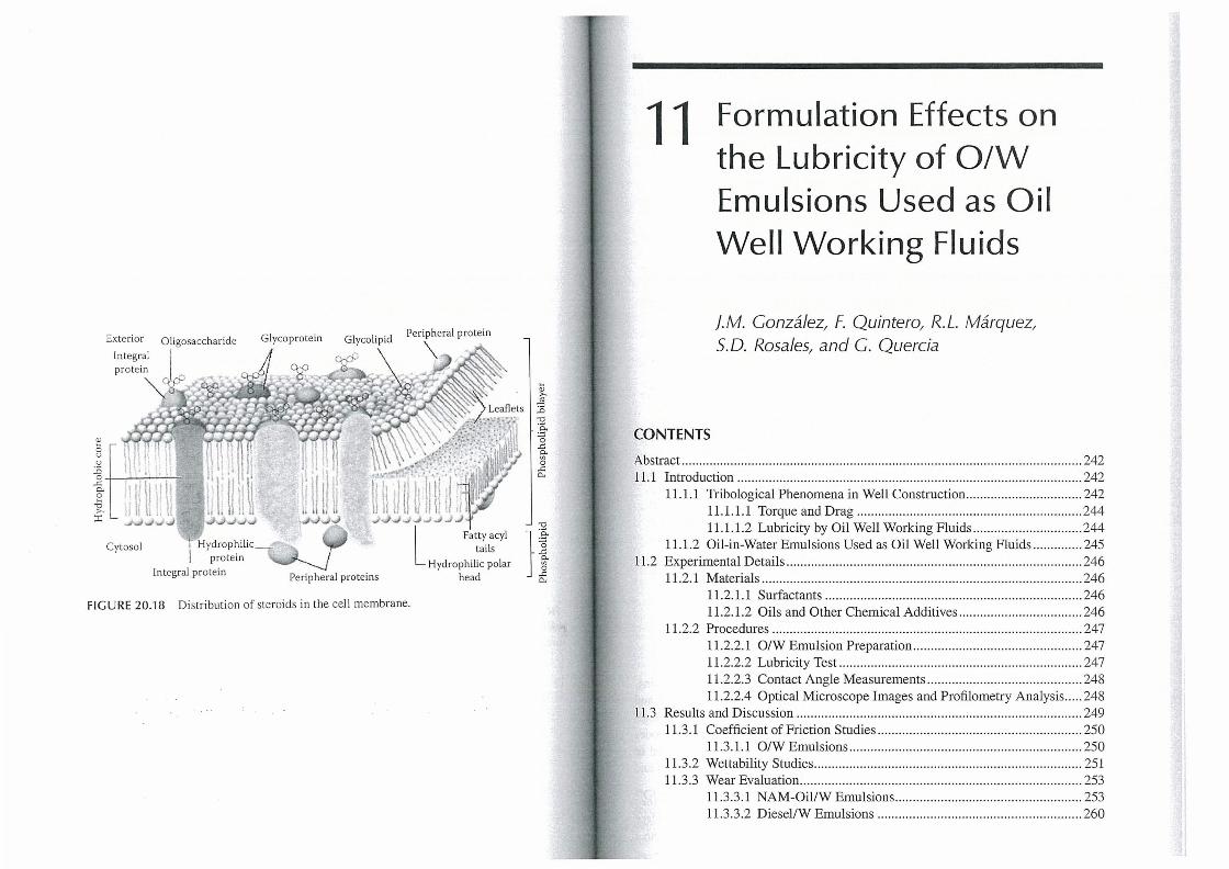
FIGURE 20.18 Distribution of steroids in the cell membrane.
11 Formulation Effects on the Lubricity of O/W Emulsions Used as Oil Well Working Fluids
/.M. Gonzalez, F. Quintero, R.L. Marquez, S. D. Rosales, and C. Quercia
CONTENTS
Abstract ....... ....... ..... ... .............. ............ .... ..... .......... ...... ....... ..... ............................. 242 11.1 Introduction ..... ................................ .... ....... ............. .......... ......... .................. 242
11.1.1 Tribological Phenomena in Well Construction ....... ... ........ .... .. ......... 242 11.1.1.1 Torque and Drag ................................................................ 244 11.1 .1.2 Lubricity by Oil Well Working Fluids ... .......... .................. 244
11.1.2 Oil-in-Water Emulsions Used as Oil Well Working Fluids .............. 245 11.2 Experimental Details ....... ............................................................................. 246
11.2.1 Materials ... ............................................. .......... ... ... .... ......... ........ ..... . 246 11.2.1.1 Surfactants ................ ... ....... ...... ...... ... ............ .. ...... ....... ..... 246 11.2.1.2 Oils and Other Chemical Additives ................................ .. . 246
11.2.2 Procedures ................... ..... .................... ........... ..... ... .... ............. ... .... . 247 11.2.2.1 O/W Emulsion Preparation .. ....... ...... .... .... .. ....... ... .... .... ..... 247 11.2.2.2 Lubricity Test .................................. .......... ...... ... ........ ..... .. . 247 11 .2.2.3 Contact Angle Measurements .. .... ...... .. ........ ... .. ... ........ ... .. . 248 11.2.2.4 Optical Microscope Images and Profilometry Analysis .. .. . 248
11.3 Results and Discussion ........ ... ... .......... ....... ...... ....... ........... .... ..... .. ...... ......... 249 11.3.1 Coefficient of Friction Studies ...... ..... ...... ....... .. .... .. .. .. .... ... ...... ... ..... . 250
11.3.1.1 O/W Emulsions ... ... ... ......... ... ..... ... .. ....... .. .... .. .. .... ...... .... .... 250 11 .3.2 Wettability Studies .... ... ...... ........ ..... .................................................. 251 11 .3.3 Wear Evaluation ............. ............ ......... ....... ......... .... .... ...... ... ...... .... .. . 253
11.3.3.1 NAM-OillWEmulsions .............. .... ....... ........ .................... 253 11.3.3.2 DiesellW Emulsions ....... ..... .... ....... ..... .. ...... .... ... ..... .... ... ... 260
242 Surfactants in Tribology
11.4 Conclusions ..... .... ...... .. ........ ......... ... ... .. ......... ... ... .. ... · .. · .. .. .. · .... ·· .... ··· .. ······ .... · 263 References ... .... ..... ... .. .... ...... ... ...... ......... .... ... .... ....... ............ .. .............. .. .. ..... ..... ..... 264
ABSTRACT
In oil well drilling, completion, and maintenance operations, the rotating pipe bears against the side of the hole at numerous points, giving rise to two main friction manifestations known as torque and drag. Torque refers to the pipe resistance to rotation and drag to hoisting and lowering. Excessive torque and drag can cause unacceptable loss of power making oil well operations less efficient, especially in high-angle and extended-reach wells. In these cases, lubricity becomes one of the main functions of the fluid. In the oil industry, there are oil well working fluids of different nature, classified according to the external phase as water-based fluids (WBFs), oil-based fluids, and pneumatic or gas-based fluid systems. Within WBFs, there are oil-in-water (O/W) emulsions, developed as a technological solution for oil well operations in low-pressure reservoirs. In this work, tribological properties of O/W emulsions have been studied as a function of their physicochemical formulation, especially oil type (nonaromatic mineral oil [NAM-oil], diesel) and surfactant concentration (1, 2% w/v) along with the oil/water ratio (70/30, 50/50) as formulation variables. The lubrication performance was established by measuring the coefficient offriction (CF), and optical microscopy imaging in conjunction with optical surface profilometry was used to evaluate antiwear properties. Additionally, contact angle measurements were performed to correlate the wettability phenomenon with the lubricity of O/W emulsions. Based on the results, it was established that with the surfactants mixture used in this study, the oil type does not have a significant effect on the CF of O/W emulsions, due to the similar wettability behavior observed at the metal surface. However, NAM-oillW emulsions have better antiwear properties than the diesel/W emulsions. Also, the lubricity performance and antiwear properties of O/W emulsions are affected by oil/water ratio and surfactants mixture concentration, showing a systemic interaction between these two parameters.
11.1 INTRODUCTION
11.1.1 TRIBOLOGICAl PHENOMENA IN WEll CONSTRUCTION
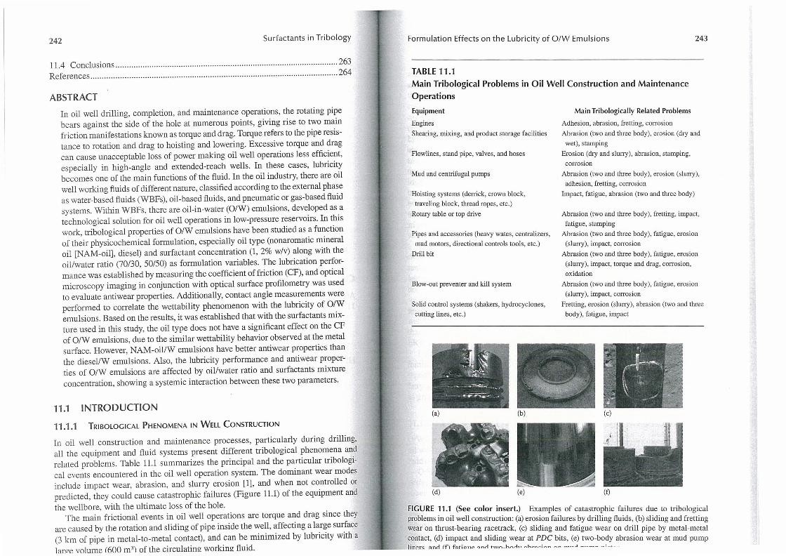
In oil well construction and maintenance processes, particularly during drilling, all the equipment and fluid systems present different tribological phenomena and related problems. Table ILl summarizes the principal and the particular tribological events encountered in the oil well operation system. The dominant wear modes include impact wear, abrasion, and slurry erosion [1], and when not controlled or predicted, they could cause catastrophic failures (Figure ILl) of the equipment and the wellbore, with the ultimate loss of the hole.
The main frictional events in oil well operations are torque and drag since they are caused by the rotation and sliding of pipe inside the well, affecting a large surface (3 km of pipe in metal-to-metal contact), and can be minimized by lubricity with a large volume (600 m3) of the circulating working fluid.
Formulation Effects on the Lubricity of O/W Emulsions 243
TABLE 11.1
Main Tribological Problems in Oil Well Construction and Maintenance Operations
Equipment
Engines
Shearing, mixing, and product storage facilities
Flowlines, stand pipe, valves, and hoses
Mud and centrifugal pumps
Hoisting systems (derrick, crown block,
traveling block, thread ropes, etc.)
Rotary table or top drive
Pipes and accessories (heavy wates, centralizers,
mud motors, directional controls tools, etc.)
Drill bit
Blow-out preventer and kill system
Solid control systems (shakers, hydrocyclones,
cutting lines, etc.)
"':',.:. \" h~ '! 1~ \ ~~
(a)
(d)
~ t~~~: ~ ~ ,
. . ... ~-i . r . .... . ;:.:
. -~".
(b)
(e)
Main Tribologically Related Problems
Adhesion, abrasion, fretting, cOJ1'osion
Abrasion (two and three body), erosion (dry and
wet), stamping
Erosion (dry and sluJ1'Y), abrasion, stamping,
corrosion
Abrasion (two and three body), erosion (slurry),
adhesion, fretting, corrosion
Impact, fatigue , abrasion (two and three body)
Abrasion (two and three body), fretting, impact,
fatigue, stamping
Abrasion (two and three body), fatigue, erosion
(slurry), impact, corrosion
Abrasion (two and three body) , fatigue, erosion
(slurry), impact, torque and drag, corrosion,
oxidation
Abrasion (two and three body), fatigue, erosion
(slurry), impact, corrosion
Fretting, erosion (slurry), abrasion (two and three
body) , fatigue, impact
(e)
(f)
FIGURE 11.1 (See color insert.) Examples of catastrophic fai lures due to tribolooical problems in oil well construction: (a) erosion failures by drilling fluids, (b) sliding and fre~ting wear on thrust-beanng racetrack, (c) sliding and fatigue wear on drill pipe by metal-metal contact, (d) impact and sliding wear at PDC bits, (e) two-body abrasion wear at mud pump l1np.r~ ~nn (f"l f~hcfllP -::anrl tn l£'\ _hr\l"h . .... h ... .. " .. ~'"' .... ...... .... ~ .... ...:I _ •• _ - - •• ! . ...
244 Surfactants in Tribology
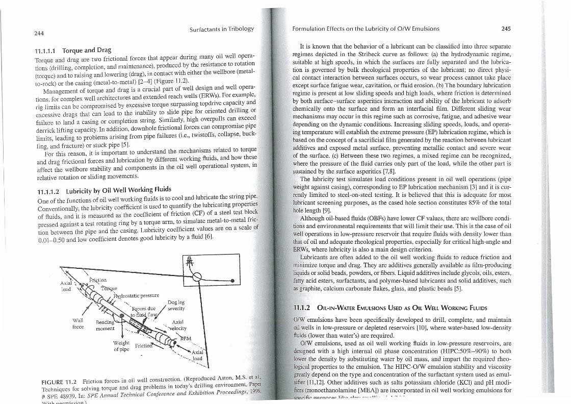
11.1.1.1 Torque and Drag Torque and drag are two frictional forces that appear during many oil well operations (drilling, completion, and maintenance), produced by the resistance to rotation (torque) and to raising and lowering (drag), in contact with either the wellbore (metalto-rock) or the casing (metal-to-metal) [2-4] (Figure 11.2).
Management of torque and drag is a crucial part of well design and well operations, for complex well architectures and extended reach wells (ERWs). For example, rig limits can be compromised by excessive torque surpassing topdrive capacity and excessive drags that can lead to the inability to slide pipe for oriented drilling or failure to land a casing or completion string. Similarly, high overpulls can exceed derrick lifting capacity. In addition, downhole frictional forces can compromise pipe limits, leading to problems arising from pipe failures (i.e., twistoffs, collapse, buck-
ling, and fracture) or stuck pipe [5]. For this reason, it is important to understand the mechanisms related to torque
and drag frictional forces and lubrication by different working fluids, and how these affect the wellbore stability and components in the oil well operational system, in
relative rotation or sliding movements.
11.1 .1.2 Lubricity by Oil Well Working Fluids One of the functions of oil well working fluids is to cool and lubricate the string pipe. Conventionally, the lubricity coefficient is used to quantify the lubricating properties of fluids and it is measured as the coefficient of friction (CF) of a steel test block pressed ~gainst a test rotating ring by a torque arm, to simulate metal-to-metal friction between the pipe and the casing. Lubricity coefficient values are on a scale of 0.01-0.50 and low coefficient denotes good lubricity by a fluid [6].
Wall force
f~ion 1C>rq.ue
~drostatic pressure " . Dog leg
moment
Weight of pipe
'. FQ.rces due / severity to flu' floy
. Axial
~' ''<elocity , RPM
FIGURE 11.2 Friction forces in oil well construction. (Reproduced Aston, M.S. et aI., Techniques for solving torque and drag problems in today's drilling environment, Paper # SPE 48939, In: SPE Annual Technical Conference and Exhibition Proceedings, 1998.
With np.rmission .l
Formulation Effects on the Lubricity of O/W Emulsions 245
It is known that the behavior of a lubricant can be classified into three separate re~imes depicted in the Stribeck curve as follows: (a) the hydrodynamic regime, s~lta?le at high speeds, in which the surfaces are fully separated and the lubrication IS governed by bulk rheological properties of the lubricant; no direct physical contact interaction between surfaces occurs, so wear process cannot take place exc~pt s.urface fatigue wear, cavitation, or fluid erosion. (b) The boundary lubrication regime IS present at low sliding speeds and high loads, where friction is determined by both surface-surface asperities interaction and ability of the lubricant to adsorb chemically onto the surface and form an interfacial film. Different slidinG wear mechanisms may occur in this regime such as corrosive, fatigue, and adhesi:e wear ~epending on the ~ynamic. conditions. Increasing sliding speeds, loads, and operatmg temperature wIll establIsh the extreme pressure (EP) lubrication regime, which is based on the concept of a sacrificial film generated by the reaction between lubricant additives and exposed metal surface, preventing metallic contact and severe wear of the surface. (c) Between these two regimes, a mixed regime can be recognized, wher~ the pressure of the fluid carries only part of the load, while the other part is sustamed by the surface asperities [7,8].
!he lub~icity test simulates load conditions present in oil well operations (pipe weight agamst casing), corresponding to EP lubrication mechanism [3] and it is current~y limited t~ steel-on-steel testing. It is believed that this is adequate for most lubncant screemng purposes, as the cased hole section constitutes 85% of the total hole length [9] .
Although oil-based fluids (OBFs) have lower CF values, there are wellbore conditions and environmental requirements that will limit their use. This is the case of oil well ope.rations in low-pressure reservoir that require fluids with density lower than that of 011 and ade~~ate. rheological properties, especially for critical high-angle and ERWs, where lubnclty IS also a main design criterion.
Lubricants are often added to the oil well workinG fluids to reduce friction and . . . b
~1l~mlZe to~que and drag. They are additives generally available as film-producing lIqUIds ?r solId beads, powders, or fibers. Liquid additives include glycols, oils, esters, fatty aCid esters, surfactants, and polymer-based lubricants and solid additives such as graphite, calcium carbonate flakes , glass, and plastic beads [5] . '
11.1 .2 OIL- IN-WATER EMULSIONS USED AS OIL WELL WORKING FLUIDS
~/W em~lsions have been specifically developed to drill, complete, and maintain oil. wells m low-pressure or depleted reservoirs [10], where water-based low-density flUIds (lower than water's) are required.
?/W em~lsions, used as oil well working fluids in low-pressure reservoirs, are deSigned With a high internal oil phase concentration (HIPC:50%-90%) to both lower the density by substituting water by oil mass, and impart the required rheological properties to the emulsion. The HIPC-O/W emulsion stability and viscosity g.reatly depend on the type and concentration of the surfactant system used as emulsIfier [11,12] . Other additives such as salts potassium chloride eKCl) and pH modifiers (monoethanolamine [MEAD are incorporated in oil well workinG emulsions for
;.....-_ SlleC.1·nr nnrnAC' o." 1~1,. ......... 1 ..... ~. ~ __ . _11 : . " ' . . . 0
246 Surfactants in Tribology
Most studies published on lubricating behavior of O/W emulsions have been done under metal working, rolling-cooling, drilling, and cutting conditions, where they have been specifically designed as lubricant fluids, with a low emulsified oil concentration (3%-5%) [13-16]. Combination of oil lubricity and the latent heat of water provides the optimum fluid for this application. Mining and petroleum machinery is also lubricated by water-based fluids (WBFs) to minimize the risk of fire from leakage of lubricants [7]. The most severe limitation of these lubricants is the temperature range in which they can be successfully applied [17].
The main objective of this work was to study the influence of oil type, dispersed oil fraction, and surfactant concentration on the tribological behavior of O/W emulsions, designed to drill, complete, and maintain high-angle and extended reached wells, located in low-pressure reservoirs, where high lubricity and low density are primary design criteria. No additives were added to the O/W emulsion formulations, assuming that the dispersed oil and/or the surfactant will provide the lubricity required, without increasing the cost of the formulation.
11.2 EXPERIMENTAL DETAilS
11.2.1 MATERIALS
11.2.1.1 Surfactants
The emulsifier system was a hydrophilic anionic/nonionic mixture at a specific mass ratio of two commercial surfactants: an alkyl ether sulfate sodium salt and an alkyl ethoxylated alcohol (made by Clariant, Venezuela); and they were used as received. The critical micelle concentration (CMC) of the aqueous surfactant solutions (ASS) and interfacial tension between the base oil and the aqueous surfactant solution were determined for the individual surfactants and the mixture, using a Dataphysics DCATlI tensiometer, employing the Wilhelmy plate technique (Table 11.2). Deionized water was used for preparing the solutions.
11.2.1.2 Oils and Other Chemical Additives
A nonaromatic mineral oil (NAM-oil) and diesel were used as the dispersed phase in the O/W emulsions. They were used as received. Table 11.3 shows the characteristics of the dispersed phases used. The salt evaluated was KCI (Sigma-Aldrich, 99%
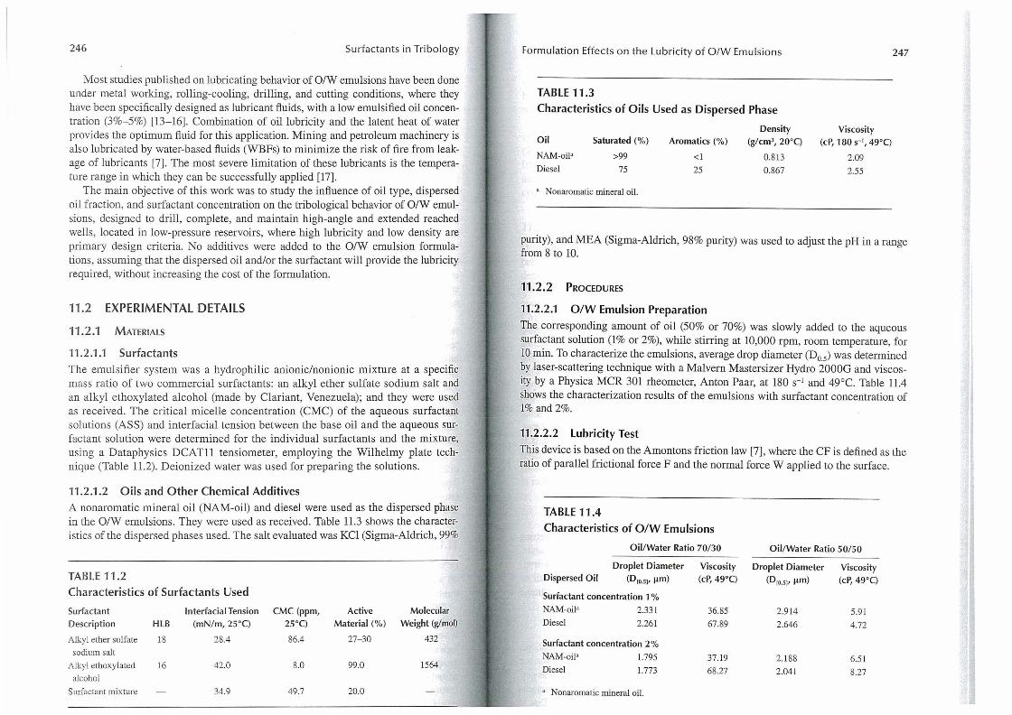
TABLE 11.2 Characteristics of Surfactants Used
Surfactant Interfacial Tension CMC (ppm, Active Molecular
Description HLB (mN/ m, 25°C) 25°C) Material (%) Weight (glmo!)
Alkyl ether sulfate 18 28.4 86.4 27-30 432
sodium salt
All)'l ethoxylated 16 42.0 8.0 99.0 1564
alcohol
Surfactant mixture 34.9 49.7 20.0
Formulation Effects on the Lubricity of O/W Emulsions
TABLE 11.3
Characteristics of Oils Used as Dispersed Phase
Oil
NAM-oil'
Diesel
Saturated (%)
>99
75
, Nonaromatic mineral oil.
Density Aromatics (%) (g/cm3,20°C)
<1 0.813 25 0.867
247
Viscosity (cP, 180 S-I, 49°C)
2.09
2.55
purity), and MEA (Sigma-Aldrich, 98% purity) was used to adjust the pH in a range from 8 to 10.
11 .2.2 PROCEDURES
11.2.2.1 O/W Emulsion Preparation
The corresponding amount of oil (50% or 70%) was slowly added to the aqueous surfactant solution (1% or 2%), while stirring at 10,000 rpm, room temperature, for 10 min. To characterize the emulsions, average drop diameter (Do.s) was determined by laser-scattering technique with a Malvern Mastersizer Hydro 2000G and viscosity by a Physic a MCR 301 rheometer, Anton Paar, at 180 S-I and 49°C. Table 11.4 shows the characterization results of the emulsions with surfactant concentration of 1% and 2%.
11.2.2.2 Lubricity Test
This device is based on the Amontons friction law [7], where the CF is defined as the ratio of parallel frictional force F and the normal force W applied to the surface.
TABLE 11.4
Characteristics of O/W Emulsions
Oil/Water Ratio 70/30 Oil/Water Ratio 50/50
Droplet Diameter Viscosity Droplet Diameter Viscosity Dispersed Oil (010.51, lim) (cP, 49°C) (0[0.51' lim) (cP,49°C)
Surfactant concentration 1 %
NAM-oil' 2.331 36.85 2.914 5.91 Diesel 2.261 67.89 2.646 4.72
Surfactant concentration 2 %
NAM-oil' 1.795 37.19 2.188 6.51 Diesel 1.773 68.27 2.041 8.27
, Nonaromatic mineral oil.
248 Surfactants in Tribology
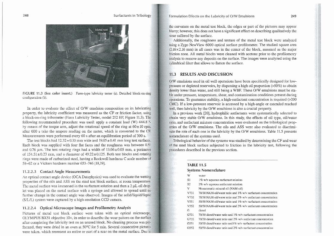
FIGURE 11.3 (See color insert.) Fann-type lubricity tester (a). Detailed block-on-ring configuration (b).
In order to evaluate the effect of O/W emulsion composition on its lubricating property, the lubricity coefficient was measured as the CF or friction factor, using a block-on-ring tribometer (Fann Lubricity Tester, model 212 EP, Figure 11.3). The following recommended procedure was used: apply a constant load (W) 444.8 N by means of the torque arm, adjust the rotational speed of the ring at 60 ± 10 rpm, after 600 s take the ampere reading on the meter, which is converted to the CF. Measurements were performed every 60 s after an equilibration period of 300 s.
The test blocks had 12.32±0.10 mm wide and 19.05 ±OA1 mm long test surfaces. Each block was supplied with four flat faces and the roughness was between 0.51 and 0.76 J..lm. The test rotating rings had a width of 13.06±0.05 mm, a perimeter of 154.51 ±0.23 mm, and a diameter of 49.22±0.125. Both test blocks and rotating rings were made of carburized steel, having a Rockwell hardness C scale number of 58-62 or a Vickers hardness number 653-746 [18,19].
11.2.2.3 Contact Angle Measurements An optical contact angle device (OCA Dataphysics) was used to evaluate the wetting properties of the oils and ASS on the steel test block surface, at room temperature. The metal surface was immersed in the surfactant solution and then a 2 J..lL oil droplet was placed on the metal surface with a syringe and allowed to spread until no further change in the contact angle was observed. Images of the solid/liquid/liquid (S/LlL) system were captured by a high-resolution CCD camera.
11.2.2.4 Optical Microscope Images and Profilometry Analysis Pictures of metal test block surface were taken with an optical microscope, OLYMPUS BX51 objective lOx, in order to describe the wear pattern on the surface after completing the lubricity test on an unused block. No cleaning process was performed, they were dried in an oven at 50°C for 5 min. Several consecutive pictures were taken. which reoresent an entire or Dart of a scar on the metal surface. Due to
Formulation Effects on the Lubricity of O/W Emulsions 249
the curvature on the metal test block, the edges or part of the pictures may appear blurry; however, this does not have a significant effect on describing qualitatively the wear suffered by the surface.
Additionally, the roughness and texture of the metal test block were analyzed using a Zygo NewView 6000 optical surface profilometer. The studied square area (2.l6 x 2.16 mm) in all cases was in the center of the block, assumed as the major friction zone. All metal blocks were cleaned with acetone prior to the profilometry analysis to remove any deposits on the surface. The images were analyzed using the cylindrical filter that allows to flatten the surface.
11.3 RESULTS AND DISCUSSION
O/W emulsions used in oil well operations have been specifically designed for lowpressure or depleted reservoirs, by dispersing a high oil proportion (>50%) to obtain density lower than water, and still being a WBF. These O/W emulsions must be stable under pressure, temperature, shear, and contamination conditions present during operations. To guarantee stability, a high-surfactant concentration is required (>200 CMC). If a low-pressure reservoir is accessed by a high-angle or extended reached well, then lubricity by the O/W emulsions is also a crucial property.
In a previous work [20], hydrophilic surfactants were systematically selected to obtain very stable O/W emulsions. In this study, the effects of oil type, oil/water ratio, and surfactant mixture concentration were evaluated on the tribological properties of the O/W emulsions. The oils and ASS were also evaluated to discriminate the role of each one in the lubricity by the O/W emulsions. Table U.5 presents nomenclature of the systems used.
Tribological behavior of the systems was studied by determining the CF and wear of the steel block surface subjected to friction in the lubricity test, following the procedures described in the previous section.
TABLE 11.5
Systems Nomenclature W water
S 1 1 % w/v aqueous surfactant solution
S2 2% w/v aqueous surfactant solution
V Nonaromatic mineral oil (NAM-oil)
V731 70/30 NAM-oillwater ratio and 1 % w/v surfactant concentration
V732 70/30 NAM-oillwater ratio and 2% w/v surfactant concentration
V551 50/50 NAM-oil/water ratio and 1 % w/v surfactant concentration
V552 50/50 NAM-oil/water ratio and 2% w/v surfactant concentration
G diesel
0731
G732
G551
G552
70/30 diesel/water ratio and 1 % w/v surfactant concentration
70/30 diesellwater ratio and 2% w/v surfactant concentration
50/50 diesel/water ratio andl % w/v surfactant concentration
50/50 diesellwater ratio and 2% w/v surfactant concentration
250 Surfactants in Tribology
The mechanisms involved in lubrication using O/W emulsions are far more complex than those involving single-phase hydrocarbon solutions. According to the literature, during O/W emulsions lubrication process, water is partially excluded from the loaded contacts due to an oil pool forming at the interface, and as a result, the performance of an O/W emulsion is close to that of the pure oil at mild operational conditions [7,15,21].
The results presented in this investigation correspond to a boundary and EP lubrication regimes, imposed by the mechanical design, and the medium-to-high pressure operational conditions of the Lubricity Tester, that simulates metal-metal friction between pipes, during oil well operations [6,22,23].
11.3.1 COEFFICIENT OF FRICTION STUDIES
11.3.1.1 O/W Emulsions
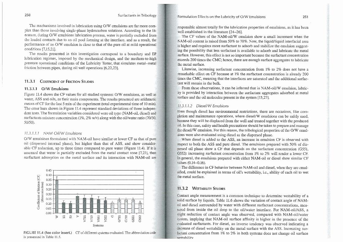
Figure 11.4 shows the CF values for all studied systems: O/W emulsions, as well as water, ASS and oils, as their main components. The results presented are arithmetic means of CF for the last 5 min of the experiment (total experimental time of 10 min). The error bars shown in Figure 11.4 represent standard deviations of three independent tests. The formulation variables considered were oil type (NAM-oil, diesel) and surfactants mixture concentration (1%, 2% w/v) along with the oil/water ratio (70/30, 50/50).
77.3.7.7.7 NAM-Oil/W Emulsions
O/W emulsions formulated with NAM-oil have similar or lower CF as that of pure oil (dispersed internal phase), but higher than that of ASS, and show considerable CF reduction, up to three times compared to pure water (Figure 11.4). If it is assumed that water is partially excluded from the metal contact zone [7,21], then surfactant adsorption on the metal surface and its interaction with NAM-oil are
0.45
8 0.40
~ 0.35
0.30
0.25
0.20
0.15
0.10
0.05
0.00
T 11
Jl Ji Jl II
r-< t.I) '" t.I)
rt I'; I ~' I ~i
> r-< '"
'" '" > > r-< l!'l l!'l
> Systems
.+ II 'I [T
=it rF r- -I r--
CF of different systems evaluated. The abbreviation code
Formulation Effects on the Lubricity of O/W Emulsions 251
responsible almost totally for the lubrication properties of emulsions, as it has been well established in the literature [24-26].
The CF values of the NAM-oil/W emulsion show a small increment when the NAM-oil content is raised from 50% to 70%. Now, the liquid/liquid interfacial area is higher and requires more surfactant to adsorb and stabilize the emulsion suggesting the possibility that less surfactant is available to adsorb and lubricate the metal surface. However, this effect is not so important because the surfactant concentration exceeds 200 times the CMC; hence, there are enough surface aggregates to lubricate the metal surface.
Likewise, increasing surfactant concentration from 1% to 2% does not have a remarkable effect on CF because at 1% the surfactant concentration is already 200 times the CMC, meaning that the interfaces are saturated and the additional surfactant will remain in the bulk.
From these observations, it can be inferred that in NAM-oil/W emulsion, lubricity is provided by interaction between the surfactant aggregates adsorbed at metal surface and the oil molecules present in the system [15,27].
77.3 .7.7.2 Oiesel/W Emulsions
Even though diesel has environmental restrictions, there are occasions, like completion and maintenance operations, where diesel/W emulsions can be safely used, because they will be displaced from the well and treated together with the produced oil. In this case, safety and health precautions should be taken to prepare and manage the diesel/W emulsion. For this reason, the tribological properties of the O/W emulsions were also evaluated using diesel as the dispersed phase.
When diesel is added to the ASS, an increase in emulsion CF is observed with respect to both the ASS and pure diesel. The emulsions prepared with 50% of dispersed oil phase show a CF that depends on the surfactant concentration (G551, G552): increasing surfactant concentration from 1% to 2% will render a lower CF. In general, the emulsions prepared with either NAM-oil or diesel show similar CF values (0.14- 0.16).
The difference in CF behavior between NAM-oil and diesel, when they are emulsified, could be explained in terms of oil's wettability, i.e., ability of each oil to wet the metal surface.
11.3.2 WETTABILITY STUDIES
Contact angle measurement is a common technique to determine wettability of a solid surface by liquids. Table 11.6 shows the variation of contact angle of NAMoil and diesel surrounded by water with different surfactant concentrations, measured from inside the oil drop to the oil/water interface. For NAM-oil/ASS, a slight reduction of contact angle was observed, compared with NAM-oil/water system, implying that NAM-oil surface affinity is higher in the presence of the evaluated surfactants. For diesel, an inverse tendency was observed indicating a decrease of diesel wettability on the metal surface with the ASS. Increasing surfactant concentration from 1% to 2% in both systems does not change oil surface FIGURE 11.4 (See color insert.)
is presented in Table ll.S. _ _ ___ _ wp.tt::lhilitv
252 Surfactants in Tribology
TABLE 11.6 Contact Angles of Two Different Oils in Aqueous Surfactant Solutions on Metal Surface
System Oil/Aqueous Contact Angle (e)
Surfactant Concentration Left (0) Right (0) Average
NAM-oil 160.3 160.4 160.4
NAM-oilll % 152.3 152.5 152.4
NAM-oi1l2% 151.0 151.1 151.1
Diesel 114.9 113.0 114.0
Diese1l1 % 156.8 156.9 156.9
Diesel/2% 155.3 155.6 155.5
Influence of surfactant concentration on the oil 's wening
propelties.
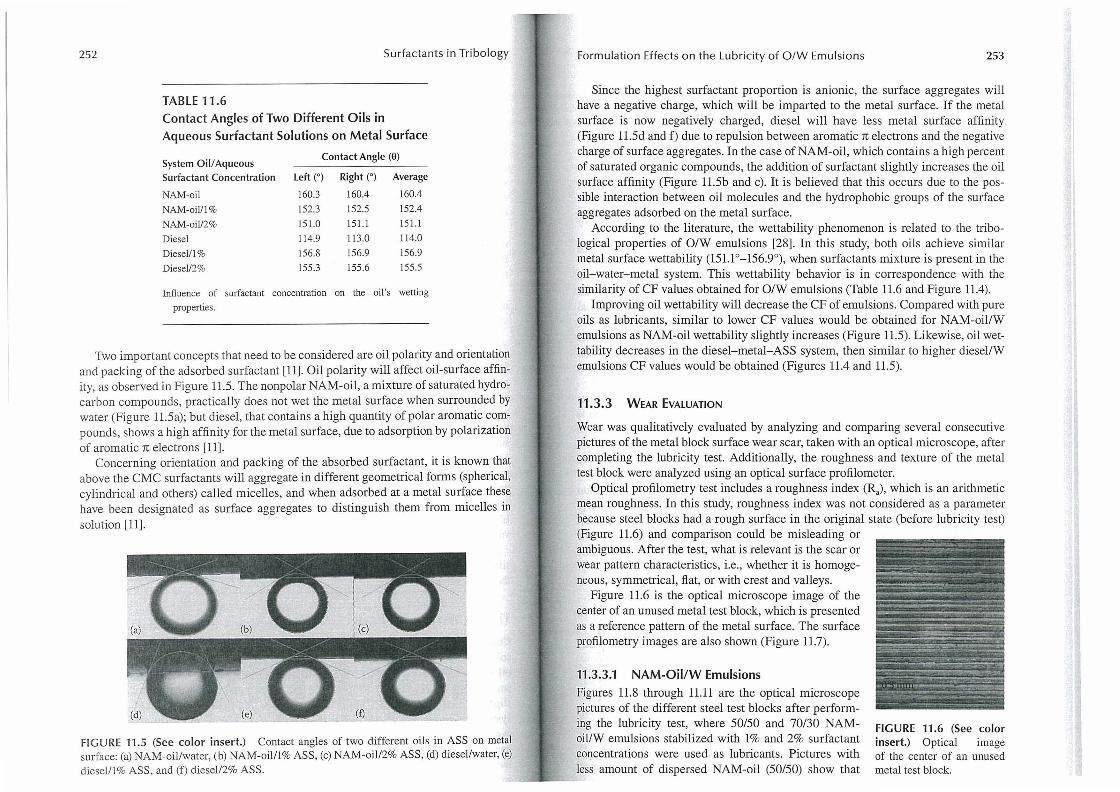
Two important concepts that need to be considered are oil polarity and orientation and packing of the adsorbed surfactant [11]. Oil polarity will affect oil-surface affinity, as observed in Figure 11.5. The nonpolar NAM-oil, a mixture of saturated hydrocarbon compounds, practically does not wet the metal surface when surrounded by water (Figure 11.5a); but diesel, that contains a high quantity of polar aromatic compounds, shows a high affinity for the metal surface, due to adsorption by polarization of aromatic 1t electrons [ll].
Concerning orientation and packing of the absorbed surfactant, it is known that above the CMC surfactants will aggregate in different geometrical forms (spherical, cylindrical and others) called micelles, and when adsorbed at a metal surface these have been designated as surface aggregates to distinguish them from micelles in solution [11].
FIGURE 11.5 (See color insert.) Contact angles of two different oils in ASS on metal surface: (a) NAM-oillwater, (b) NAM-oilll% ASS, (c) NAM-oil /2% ASS, (d) diesellwater, (e) diesel/1% ASS, and (f) diesell2% ASS. - - --- -
Formulation Effects on the Lubricity of O/W Emulsions 253
Since the highest surfactant proportion is anionic, the surface aggregates will have a negative charge, which will be imparted to the metal surface. If the metal surface is now negatively charged, diesel will have less metal surface affinity (Figure 11.5d and f) due to repulsion between aromatic 1t electrons and the negative charge of surface aggregates. In the case of NAM -oil, which contains a high percent of saturated organic compounds, the addition of surfactant slightly increases the oil surface affinity (Figure 11.5b and c). It is believed that this occurs due to the possible interaction between oil molecules and the hydrophobic groups of the surface aggregates adsorbed on the metal surface.
According to the literature, the wettability phenomenon is related to the tribological properties of O/W emulsions [28]. In this study, both oils achieve similar metal surface wettability (151.1°-156.9°), when surfactants mixture is present in the oil-water-metal system. This wettability behavior is in correspondence with the similarity of CF values obtained for O/W emulsions (Table 11.6 and Figure 11.4).
Improving oil wettability will decrease the CF of emulsions. Compared with pure oils as lubricants, similar to lower CF values would be obtained for NAM-oil/W emulsions as NAM-oil wettability slightly increases (Figure 11.5). Likewise, oil wettability decreases in the diesel-metal-ASS system, then similar to higher diesel/W emulsions CF values would be obtained (Figures 11.4 and 11.5).
11 .3.3 WEAR EVALUATION
Wear was qualitatively evaluated by analyzing and comparing several consecutive pictures of the metal block surface wear scar, taken with an optical microscope, after completing the lubricity test. Additionally, the roughness and texture of the metal test block were analyzed using an optical surface profilometer.
Optical profilometry test includes a roughness index (Ra)' which is an arithmetic mean roughness. In this study, roughness index was not considered as a parameter because steel blocks had a rough surface in the original state (before lubricity test) (Figure 11.6) and comparison could be misleading or ambiguous. After the test, what is relevant is the scar or wear pattern characteristics, i.e., whether it is homogeneous, symmetrical, fiat, or with crest and valleys.
Figure 11.6 is the optical microscope image of the center of an unused metal test block, which is presented as a reference pattern of the metal surface. The surface profilometry images are also shown (Figure 11.7).
11.3.3.1 NAM-OiI/W Emulsions
Figures U.8 through 11.11 are the optical microscope pictures of the different steel test blocks after perform-ing the lubricity test, where 50/50 and 70/30 NAMoil/W emulsions stabilized with 1% and 2% surfactant concentrations were used as lubricants. Pictures with less amount of dispersed NAM-oil (50/50) show that
FIGURE 11.6 (See color insert.) Optical image of the center of an unused metal test block.
254 Surfactants in Tribology
(a) (b)
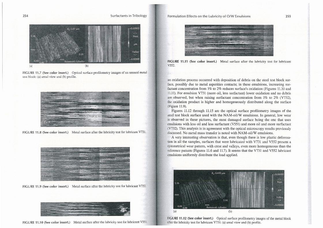
FIGURE 11 .7 (See color insert.) Optical surface profilometry images of an unused metal test block: (a) areal view and (b) profile.
FIGURE 11.8 (See color insert.) Metal surface after the lubricity test for lubricant V731.
FIGURE 11.9 (See color insert.) Metal surface after the lubricity test for lubricant V732.
FIGURE 11.10 (See color insert.) Metal surface after the lubricity test for lubricant V551. - --'- -
Formulation Effects on the Lubricity of O/W Emulsions 255
FIGURE 11.11 (See color insert.) Metal surface after the lubricity test for lubricant V552.
an oxidation process occurred with deposition of debris on the steel test block surface, possibly due to metal asperities contacts; in these emulsions, increasing surfactant concentration from 1% to 2% reduces surface's oxidation (Figures 11.10 and 11.11). For emulsion V731 (more oil, less surfactant) lower oxidation and no debris are observed, but when raising surfactant concentration from 1% to 2% (V732), the oxidation product is higher and homogeneously distributed along the surface (Figure 11.9).
Figures 11.12 through 11.15 are the optical surface profilometry images of the steel test block surface used with the NAM-oillW emulsions. In general, low wear is observed in these pictures, the most damaged surface being the one that uses emulsions with less oil and less surfactant (V551) and more oil and more surfactant (V732). This analysis is in agreement with the optical microscopy results previously discussed. No metal mass transfer is noted with NAM-oiI/W emulsions.
A very interesting observation is that, even though there is low plastic deformation in all the samples, surfaces that were lubricated with V731 and V552 present a symmetrical wear pattern, with crest and valleys, even more homogeneous than the reference pattern (Figures 11.6 and 11.7). It seems that the V731 and V552 lubricant emulsions uniformly distribute the load applied.
R,: 0.692 ~m , ... : .• t~ .. 1-'-·--llllril l. ~ .'I.. . ,
~' ~ 'iIIl··' :'· ' +8.00000
2.16 " , ..... .': . "1"1' I ~~ 1 , I' i ~ijl~1 ~j P::k '. .', ". ( . . t . ',: .. '" . "'. '........ ' l~'! ll'lll~·; '~: 1"I:C;l ... ';· Ii ~m mill . ' . . • -".~ ," I '. ~.,"
, ,,- . . ' " .; . Valley
." 2.16 I _ l : _ ~. ;1, -v
0.00 . . mm "" " -8.00000 000 ',mo',"","od" ~,
•
FIGURE 11.12 (See color insert.) Optical surface profilometry images of the metal block after the lubricity test for lubricant V731: (a) areal view and (b) profile.
256 Surfactants in Tribology
(a) (b)
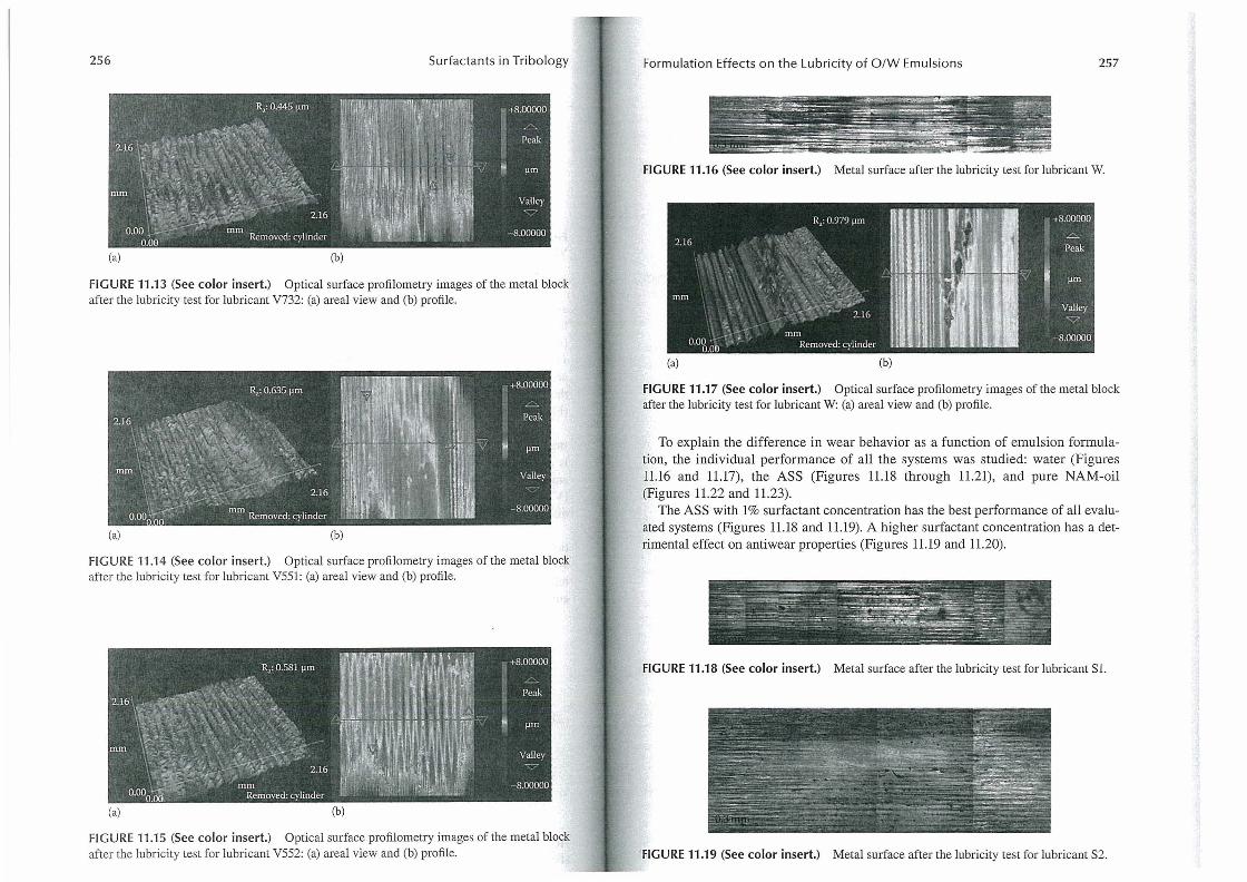
FIGURE 11.13 (See color insert.) Optical surface profilometry images of the metal block after the lubricity test for lubricant V732: (a) areal view and (b) profile.
(a) (b)
FIGURE 11.14 (See color insert.) Optical surface profilometry images of the metal block after the lubricity test for lubricant V551: (a) areal view and (b) profile.
(a) (b)
FIGURE 11 .15 (See color insert.) Optical surface profilometry images of the metal block after the lubricity test for lubricant V552: (a) areal view and (b) profile.
Formulation Effects on the Lubricity of O/W Emulsions 257
FIGURE 11.16 (See color insert.) Metal surface after the lubricity test for lubricant W.
(a) (b)
FIGURE 11.17 (See color insert.) Optical surface profilometry images of the metal block after the lubricity test for lubricant W: (a) areal view and (b) profile.
To explain the difference in wear behavior as a function of emulsion formulation, the individual performance of all the systems was studied: water (Figures 11.16 and 11.17), the ASS (Figures 11.18 through 11.21), and pure NAM-oil (Figures 11.22 and 11.23).
The ASS with 1% surfactant concentration has the best performance of all evaluated systems (Figures 11.18 and 11.19). A higher surfactant concentration has a detrimental effect on antiwear properties (Figures 11.19 and 11.20).
FIGURE 11.18 (See color insert.) Metal surface after the lubricity test for lubricant S1.
' FIGURE 11.19 (See color insert.) Metal surface after the lubricity test for lubricant S2.
258 Surfactants in Tribology
(a) (b)
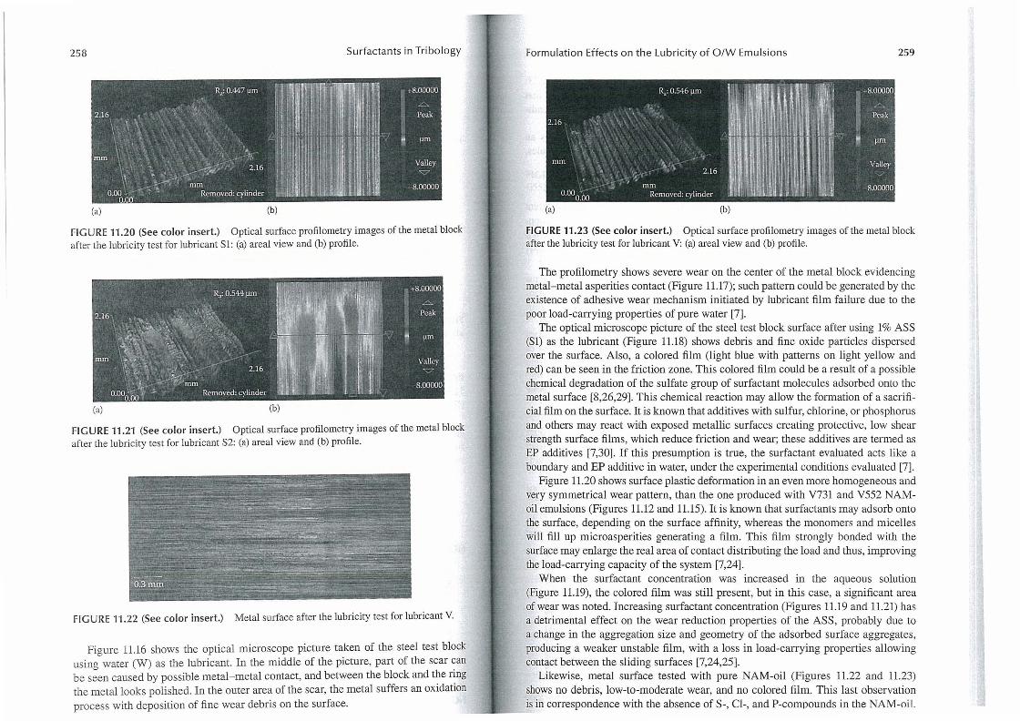
FIGURE 11.20 (See color insert.) Optical surface profilometry images of the metal block after the lubricity test for lubricant Sl: (a) areal view and (b) profile.
(a) (b)
FIGURE 11.21 (See color insert.) Optical surface profilometry images of the metal block after the lubricity test for lubricant S2: (a) areal view and (b) profile.
FI G U RE 11.22 (See color insert.) Metal surface after the lubricity test for lubricant V.
Figure 11.16 shows the optical microscope picture taken of the steel test block usincr water (W) as the lubricant. In the middle of the picture, part of the scar can be s:en caused by possible metal-metal contact, and between the block and the ring the metal looks polished. In the outer area of the scar, the metal suffers an oxidation process with deposition of fine wear debris on the surface. ----
Formulation Effects on the Lubricity of O /W Emulsions 259
, R,: 0.546 ~m ~' ~~.'ji .~.~~~ .. ~"'~!';m: ",,;,, 1' '~.! ~. +8.00000 :, -.,:' ";;t , ,. ! I ~'/'"
o 16 "':-.' . '., ,', . . '. 'f· . I. Peak _. . . .. .. " ' i I ! . ! • . . .... ,I ',~ " .. ' " .. \ . :\: I~~I\~ I I ~·I· IlL .:~~ • ~ mm •. :. '<. . '.' , .~: \ ~. .~ 16 ' . .. . I .,. .'1 Yalley
, .. ~.:.; /~'mm ' .: , !: ,I / 0.00
0:00
' Removed: cylinder . ,~ . . 'Li • fa. h: '!'~ -8.00000
(a) (b)
FIGURE 11.23 (See color insert,) Optical surface profilometry images of the metal block after the lubricity test for lubricant V: (a) areal view and (b) profile.
The profilometry shows severe wear on the center of the metal block evidencing metal-metal asperities contact (Figure 11.17); such pattern could be generated by the existence of adhesive wear mechanism initiated by lubricant film failure due to the poor load-carrying properties of pure water [7].
The optical microscope picture of the steel test block surface after using 1% ASS (Sl) as the lubricant (Figure 11.18) shows debris and fine oxide particles dispersed over the surface. Also, a colored film (light blue with patterns on light yellow and red) can be seen in the friction zone. This colored film could be a result of a possible chemical degradation of the sulfate group of surfactant molecules adsorbed onto the metal surface [8,26,29]. This chemical reaction may allow the formation of a sacrificial film on the surface. It is known that additives with sulfur, chlorine, or phosphorus and others may react with exposed metallic surfaces creating protective, low shear strength surface films, which reduce friction and wear; these additives are termed as EP additives [7,30]. If this presumption is true, the surfactant evaluated acts like a boundary and EP additive in water, under the experimental conditions evaluated [7].
Figure 11.20 shows surface plastic deformation in an even more homogeneous and very symmetrical wear pattern, than the one produced with V731 and V552 NAMoil emulsions (Figures 11.12 and 11.15). It is known that surfactants may adsorb onto the surface, depending on the surface affinity, whereas the monomers and micelles will fill up microasperities generating a film. This film strongly bonded with the surface may enlarge the real area of contact distributing the load and thus, improving the load-carrying capacity of the system [7,24].
When the surfactant concentration was increased in the aqueous solution (Figure 11.19), the colored film was still present, but in this case, a significant area of wear was noted. Increasing surfactant concentration (Figures 11.19 and 11.21) has a detrimental effect on the wear reduction properties of the ASS, probably due to a change in the aggregation size and geometry of the adsorbed surface aggregates, producing a weaker unstable film, with a loss in load-carrying properties allowing contact between the sliding surfaces [7,24,25].
Likewise, metal surface tested with pure NAM-oil (Figures 11.22 and 11.23) shows no debris, low-to-moderate wear, and no colored film. This last observation is in correspondence with the absence of S-, Cl-, and P-compounds in the NAM-oil.
260 Surfactants in Tribology
which would react with the metal surface [8]. Profilometry analysis (Figure 11.23) presents a symmetrical and homogeneous wear pattern, similar to Sl , implying that NAM-oil also possesses good load-carrying capacity under the experimental conditions evaluated.
These results allow to propose that the film with the best performance is an ordered structure formed by the adsorbed surface aggregates and oil molecules, which is determined by oil and surfactant concentrations [11,27,28].
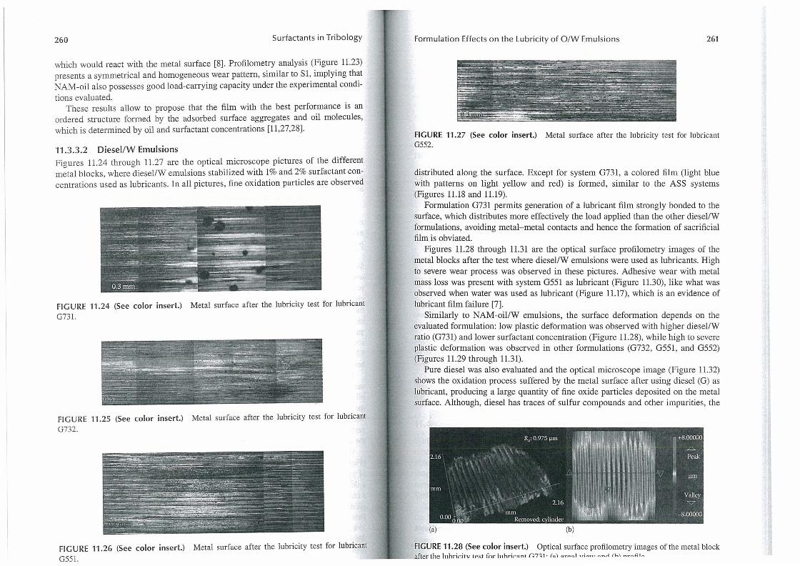
11.3.3.2 DiesellW Emulsions Figures 11.24 through 11.27 are the optical microscope pictures of the different metal blocks , where diesel/W emulsions stabilized with 1% and 2% surfactant concentrations used as lubricants. In all pictures, fine oxidation particles are observed
FIGURE 11 .24 (See color insert.) Metal surface after the lubricity test for lubricant G731.
FIGURE 11.25 (See color insert.) Metal surface after the lubricity test for lubricant G732.
Formulation Effects on the Lubricity of O/W Emulsions 261
FIGURE 11.27 (See color insert.) Metal surface after the lubricity test for lubricant G552.
distributed along the surface. Except for system 0731, a colored film (light blue with patterns on light yellow and red) is formed, similar to the ASS systems (Figures 11.18 and 11.19).
Formulation 0731 permits generation of a lubricant film strongly bonded to the surface, which distributes more effectively the load applied than the other diesel/W formulations, avoiding metal-metal contacts and hence the formation of sacrificial film is obviated.
Figures 11.28 through 11.31 are the optical surface profilometry images of the metal blocks after the test where diesel/W emulsions were used as lubricants. High to severe wear process was observed in these pictures. Adhesive wear with metal mass loss was present with system 0551 as lubricant (Figure 11.30), like what was observed when water was used as lubricant (Figure 11.17), which is an evidence of lubricant film failure [7].
Similarly to NAM-oil/W emulsions, the surface deformation depends on the evaluated formulation: low plastic deformation was observed with higher diesel/W ratio (0731) and lower surfactant concentration (Figure 11.28), while high to severe plastic deformation was observed in other formulations (0732, 0551, and 0552) (Figures 11.29 through 11.31).
Pure diesel was also evaluated and the optical microscope image (Figure 11.32) shows the oxidation process suffered by the metal surface after using diesel (0) as lubricant, producing a large quantity of fine oxide particles deposited on the metal surface. Although, diesel has traces of sulfur compounds and other impurities, the
(a) (b)
FIGURE 11.26 (See color insert.) Metal surface after the lubricity test for lubricant FIGURE 11.28 (See color insert.) Optical surface profilometry images of the metal block G551. _ _ ~ _ _ ,after the 111hrir.ilv 11>.<1 for Jllh,·iro nt r.T'll· (0\ or~ol ";~n ' ~~rI (h' - .. ~" ' -

262 Surfactants in Tribology
(a) (b)
FI G U RE 11.29 (See color insert.) Optical surface profilometry images of the metal block after the lubricity test for lubricant G732: (a) areal view and (b) profile.
FIGURE 11.30 (See color insert.) Optical surface profilometry images of the metal block after the lubricity test for lubricant G551: (a) areal view and (b) profile.
(a) (b)
FIGURE 11.31 (See color insert.) Optical surface profilometry images of the metal block after the lubricity test for lubricant G552: (a) areal view and (b) profile.
Formulation Effects on the Lubricity of O/W Emulsions 263
FIGURE 11.32 (See color insert.) Metal surface after the lubricity test for lubricant G.
(a) (b)
FIGURE 11.33 (See color insert.) Optical surface profilometry images of the metal block after the lubricity test for lubricant G: (a) areal view and (b) profile.
colored film was not observed, meaning that the colored (sacrificial) film is produced by the possible reaction of the adsorbed surfactant molecules with surface metal atoms, producing colored metallic sulfur salts [7,8,29].
Optical surface profilometry image (Figure 11.33) of the metal block tested with diesel (G) presents high wear accompanied by high plastic deformation bordering the friction zone.
11.4 CONCLUSIONS
With the surfactants mixture used in this study, the oil type does not have a significant effect on the CF of O/W emulsions due to the similar wettability behavior observed at the metal surface. However, NAM-oil/W emulsions have better antiwear properties than the diesel/W emulsions. This implies that conventional CF measurements are not enough to evaluate lubricating properties of oil well working fluids. Surface analysis must be done to compare anti wear performance.
Under the evaluated test conditions and with the specified surfactants mixture, the lubricity performance and anti wear properties of O/W emulsions are affected by oil/water ratio and surfactants mixture concentration, showing a systemic interaction between these two parameters. Being under a boundary and EP lubrication
264 Surfactants in Tribology
regimes, emulsion viscosity and droplet size do not have any effect on the lubricating properties.
The film formed at metal surface with all NAM-oillW emulsions and diesel (70)/W(30) emulsion with 1% surfactant concentration can withstand loads higher than 488 N before entering in the EP lubrication regime. All other evaluated systems fall in the EP lubrication regime at lower loads and where they will form a sacrificial film if surfactant is present.
The 1% surfactants mixture studied could be used as a lubricant additive for pure water-based oil well working fluids.
REFERENCES
1. J.J. Truhan, R. Menon, and P.J. Blau. The evaluation of various cladding materials for down-hole drilling applications using the pin-on-disk test. Wear 259, 1308-1313 (2005).
2. R. Caenn and G.Y. Chillingar. Drilling fluids: State of art. Petrol. Sci. Eng. 14, 221-230 (1996).
3. M. Zamora and M. Stephens. Drilling fluids. In: Petroleum Well Construction. Chapter 5: pp. 119-142, John Wiley & Son Ltd., England (1998).
4. W.E. Foxenberg, S.A. Ali, T.P. Long, and J. Viano Field experience shows that new lubricant reduces friction and improves formation compatibility and environmental impact. Paper # SPE 112483. In: SPE International Symposium and Exhibition on Formation Damage Control Proceedings (2008).
5. M.S. Aston, P.J. Hearn, and G. McGhee. Techniques for solving torque and drag problems in today's drilling environment. Paper # SPE 48939. In: SPE Annual Technical Conference and Exhibition Proceedings (1998).
6. J.D. Kercheville, A.A. Hinds, and W.R Clements. Comparison of environmentally acceptable materials with diesel oil for drilling mud lubricity and spotting fluid formulations. Paper # lADC/SPE 14797. In: IADC/SPE Drilling Conference Proceedings (1986).
7. G. Stachowiak and A.W. Batchelor. Engineering Tribology, 2nd edn., Chapter 1: pp. 1-7, Chapter 2: pp. 11-45, Chapter 3: pp. 51-95, Chapter 8: pp. 357-404, Chapter 12: pp. 533-550, Butterwort-Heinemann Inc. , Boston, MA (2001).
8. S.M. Hsu. Molecular basis oflubrication. Tribol. Int. 37, 553-559 (2004). 9. J. Holand, S.A. Kvamme, T.H. Omland, A. Saasen, and K. Taugbol. Lubricants
enabled completion of ERD well paper # IADC/SPE 105730. In: IADC/SP E A Drilling Conference Proceedings (2007) .
10. J. Blanco, Inventor; L. Quintero, Inventor. PDVSA Intevep, S.A., assignee. Well stimulation with hydrophilic fluids. United States of America, U.S. patent 5783525 (July 21, 1998).
11. M.J. Rosen. SUlfactants and Inte/facial Phenomena, 3rd edn., Chapter 2: pp. 35-95, Chapter 6: pp. 243-268, Chapter 8: pp. 306-320, John Wiley & Sons, Hoboken, NJ (2004).
12. L. Becu, P. Grondin, A. Colin, and S. Manneville. How does a concentrated emulsion flow? Yielding, local rheology, and wall slip. Colloids SUIt 263, 146-152 (2004).
13. Z. Pawlak, B.E. Klamecki, T. Rauckyte, G.P. Shpenkov, and A. Kopkowski. The tribochemical and micellar aspects of cutting fluids. Tribol. Int. 38, 1-4 (2005).
14. A.K. Tieu, P.B . Kosasih, and A. Godbole. A thermal analysis of strip-rolling in mixedfilm lubrication with O/W emulsions. Tribol. Int. 39, 1591-1600 (2006).
Formulation Effects on the Lubricity of O/W Emulsions 265
15. A. Cambiella, J.M. Benito, e. Pazos, J. Coca, A. Hernandez, and J.E. Fernandez. Formulation of emulsifiable cutting fluids and extreme pressure behavior. 1. Mater. Proc. Technol. 184, 139-145 (2007).
16. U.C. Chen, Y.S. Liu, C.C. Chang, and J.F Lin. The effect of the additive concenu'ation in emulsions to the tribological behavior of a cold rolling tube under sliding contact. Tribol. Int. 35, 309-320 (2002).
17. K.R Januszkiewicz, A.R. Riahi, and S. Barakat. High temperature tribological behavior of lubricating emulsions. Wear 256, 1050-1061 (2004).
18. ASTM D 2509-03. Standard Test Method for Measurement of Load-Carrying Capacity of Lubricating Grease (Timken Method). 326/83 (88). Reapproved 2008.
19. ASTM D 2782-02. Standard Test Method for Measurement of Extreme-Pressure of Lubricating Fluids (Timken Method). 240/84. Reapproved 2008.
20. F. Quintero, RL. Marquez, J.M. Gonzalez, and S.D. Rosales Anzola. Formulation effects on the stability of drilling oil/water emulsions based on interfacial dilatational rheology and light scattering techniques. Paper presented at the 17th International Symposium on SUlfactants in Solution (SIS), Berlin, Germany (August 2008).
21. A. Chojnicka, G. Sala, e.G. Kruif, and F. Van de Velde. The interactions between oil droplets and gel matrix affect the lubrication properties of sheared emulsion-filled gels. Food Hydrocolloids 23, 1038-1046 (2009).
22. EP/Lubricity Tester, Manual oj Operation. Baroid Division NL Indusu'ies, Inc., Houston, TX (1983).
23. R.H. Sifferman, T.M.M. Muijs, G.F. Fanta, F.C. Felker, and S.M. Erhan. Starch-lubricant compositions for improved lubricity and fluid loss in water-based drilling muds. Paper # SPE 80213. In: SPE International Symposium on Oilfield Chemistry Proceedings (2003).
24. M.W. Sulek and T. Wasilewski. Tribological properties of aqueous solutions of alkyl polyglucosides. Wear 260, 193-204 (2006).
25. M. Graca, J. Bongaerts, J.R Stokes, and S. Granick. J. Friction and adsorption of aqueous polyoxyethylene (Tween) smiactants at hydrophobic surfaces. Colloid Inte/face Sci. 315,662-670 (2007).
26. S.K. Misra and RO. Skbld. Lubrication studies of aqueous mixtures of inversely soluble components. Colloids Surf. A: Physicochem. Eng. Asp. 170, 91-106 (2000).
27. T. Wasilewski and M.W. Sulek. Paraffin oil solution of the mixture of sorbitan monolaurate-ethoxilated sorbitan monolaurate as lubricants. Wear 261 , 230-234 (2006).
28. A. Cambiella, J.M. Benito, e. Pazos, and J. Coca. Interfacial properties of oil-in-water emulsions designed to be used as metalworking fluids. Colloids Surf. A: Physicochem. Eng. Asp. 305, 112-119 (2007).
29. B.K. Sharma, A. Adhvaryu, and S.Z. Erhan. Friction and wear behavior of thioether hydroxy vegetable oil. Tribol. Int. 42, 353-358 (2009).
30. O. Furlong, F. Gao, P. Kotvis, and w.T. Tysoe. Understanding the tribological chemistry of chlorine-, sulphur- and phosphorus-containing additives. Tribol. Int. 40, 699-708 (2008).