formal assurance for cognitive architecture based
TRANSCRIPT
Formal Assurance for Cognitive ArchitectureBased Autonomous Agent
Siddhartha Bhattacharyya, Thomas C. Eskridge, Natasha Neogi, and MarcoCarvalho
Florida Institute of Technology,School of Computing, Melbourne, FL
NASA,Langley
{sbhattacharyya,teskridge,mcarvalho}@fit.edu
{natasha.a.neogi}@nasa.gov
Abstract. Autonomous systems are designed and deployed in differentmodeling paradigms. These environments focus on specific concepts indesigning the system. We focus our effort in the use of cognitive ar-chitectures to design autonomous agents to collaborate with humans toaccomplish tasks in a mission. Our research focuses on introducing for-mal assurance methods to verify the behavior of agents designed in Soar,by translating the agent to the formal verification environment Uppaal.
Keywords: formal verification, human-machine team assurance
1 Introduction
Autonomous systems are increasingly being designed in different modeling paradigms.Each of these focus on specific aspects of the design. For example, some methodsare based on an architectural modular approach with rule based design, whereasothers are focused on finite automata based models. In our research effort we fo-cus on the design of autonomous agents based on the Soar cognitive architecture,which is a rule based system. The benefits of Soar are as follows:
– Allows for the representation and modeling of procedure oriented autonomousagents,
– Enables the modeling of human machine interactions.
These environments provide the paradigm to model autonomous agents, butlack the capability for rigorous analysis to prove the satisfaction of properties.In our approach, we discuss the initial version of the automated translator wehave developed, and more specifically how this translation is achieved througha model transformation from Soar to Uppaal. This technique provides a proofof concept for how the formal assurance of cognitive models could allow verifiedagents to be designed for safety critical applications. In section 2, we discussbriefly the design of an autonomous agent in Soar. We then follow this with a
https://ntrs.nasa.gov/search.jsp?R=20170005470 2017-12-20T17:01:20+00:00Z

2 LNCS
discussion of decision procedures in section 3, and elaborate on the productionsystem executing rules in Soar. The formal verification environment Uppaal isdiscussed in Section 4, followed by a description of the automated translationprocess in Section 5. Finally we discuss the engine out case study in Section 6.
Previous work Research efforts in the area of verification of adaptive archi-tectures include work done on Rainbow CMU [1], [2] which focuses on dynamicsystem adaptation via architecture models. It also investigates formal guaranteesfor synthesis of adaptive strategies. Research conducted by Topcu [3] focuses onconstraining the inputs to learning systems in order to synthesize systems thatare correct by construction. Sharifloo in [4] describes the use of light weight for-mal verification methods for runtime assurance when a system is updated witha new component. None of these efforts have provided support for rigorouslyanalyzing existing adaptive decision procedures implemented through cognitivearchitectures. Thus, the approach in this paper is unique in performing formalverification of the production rules of a potentially learning system in a cognitivearchitecture.
2 Autonomous agents in Soar
Our investigation into the formal verification of adaptive intelligent systems fo-cuses on agents constructed using cognitive architectures, such as Soar or ACT-R[5, 6]. Such agents can be used to develop new adaptive, intelligent systems foruse in cybersecurity command and control [7, 8] or adaptive, intelligent process-ing [9].
In this research effort the Soar cognitive architecture is used to design anautonomous agent that performs the decision-making processes of a co-pilot ofa large, multi-engine aircraft. We have modeled the co-pilot decision-makingresponsibilities for normal take off and single engine out procedures. The cur-rent research is based on earlier work developing Soar agents that modeledreinforcement-based learning of optimal item ordering of take-off checklists andof drone navigation in enclosed areas [10]. Figure 1 shows a block diagram ofthe latter work, where the Decision Agent could learn acceptable flight paths bywatching the training paths flown by a human operator.
3 Production System Decision Procedures
Production systems have been a popular method in Artificial Intelligence forproducing intelligent behavior that is understandable to the program operator[11, 12, 5, 6]. Productions systems represent knowledge as a set of “if-then” rulesthat map between states of the system and actions that can initiate sensingand take actions. For our drone navigation application, we developed a set ofrules that navigated a quad-copter through a flight space with simple obstacles(i.e., regular, flat walls). The rules monitored the location and aircraft speed,

LNCS 3
Fig. 1. Overview of the prototype system.
direction, and attitude on the “if” side of the rules (the condition variables),and made direction and attitude adjustments on the “then” side (the modifiedvariables).
Adaptation in the Decision Agent occurs in two ways: First, a reinforcementlearning procedure is executed to determine the best ordering of individual stepsin a checklist [13]. The adaptation from reinforcement learning here does not alterthe content of the rules, but instead alters the order of execution of the rules toresult in the least overall time spent [14].
Second, Soar’s “chunking” feature is used to collapse a number of rules thatare commonly executed as a sequence into a single rule. This feature does modifythe contents of the rules executed by the Decision Agent, and therefore intro-duces some uncertainty in the validity of the new rules.
The question that is answered by this research is “Is the ruleset that resultsfrom the adaptation valid?”. That is, does it meet the progress and safety re-quirements demanded by the operator or mission, while improving its efficiencyor performance?
4 Formal Verification: Uppaal
The goal of the translation is to map the cognitive model into a formal language,where progress and safety requirements can be verified completely. There areseveral options for the formal language. We have chosen to map to the formalismsof the language supported by Uppaal. Models in Uppaal are finite state machines.The composition of the rules as finite state machines allows the representationof formal modeling using temporal logics. This modeling paradigm allows theexecution of requirements as temporal logic queries to exhaustively check thesatisfaction of the properties. We describe the mathematical representation andthe different properties that can be verified next.

4 LNCS
4.1 Mathematical Representation in Uppaal
The rules are translated to formal, mathematically rigorous representations knownas timed automata, a subset of hybrid automata. According to timed automata,one of the essential requirements in the design is to model the time associatedwith the execution of operations or rules. To represent time, the componentsneed be modeled as timed automata. A timed automaton is a finite automatonextended with a finite set of real-valued clocks. Clock or other relevant variablevalues can be used in guards on the transitions within the automata. Based onthe results of the guard evaluation, a transition may be enabled or disabled.Additionally, variables can be reset and implemented as invariants at a state.Modeling timed systems using a timed-automata approach is symbolic ratherthan explicit and is similar to program graphs. This allows verification of safetyproperties to be a tractable problem rather than an intractable infinite one withcontinuous time. So timed automata consider a nite subset of the innite statespace on-demand, i.e., using an equivalence that depends on the property andthe timed automaton, which is referred to as the region automaton.
Timed automata can be used to model and analyze the timing behavior ofcomputer systems, e.g., real-time systems or networks. Methods for checkingboth safety and liveness properties have been developed. It has been shown thatthe state reachability problem for timed automata is decidable, which makes thisan interesting sub-class of hybrid automata. Extensions have been extensivelystudied, among them stopwatches, real-time tasks, cost functions, and timedgames. There exists a variety of tools to input and analyze timed automataand extensions, including the model checkers Uppaal, Kronos, and TemporalLogic Actions (TLA). These tools are becoming more and more mature. Formalrepresentation of timed automata is defined below.
Formally, timed automata can be defined as (Q, inv, , C, E, q0) where Q is finiteset of states or locations inv are location invariants Σ is finite set of events oractions C is finite set of clocks E a set of edges, where an edge is a tuple (q, g, ,r, q) defining a transition from state q to state q with a guard or clock constraintg, an action or event , and an update or reset r.q0 is the initial state or location
4.2 Formal verification of autonomous behaviors
The translation of a cognitive model to a formal methods environment support-ing temporal logics allows the formulation of properties as described next.
– E<> p it is possible to reach a state in which p is satisfied, i.e., p is true in(at least) one reachable state (Figure 2 a).
– A[] p p holds invariantly, i.e., p is true in all reachable states (Figure 2 b).– A<> p: The automaton is guaranteed to eventually reach a state in which
p is true, i.e., p is true in some state of all paths (Figure 2 c).– E[] p p is potentially always true, i.e., there exists a path in which p is true
in all states (Figure 2 d).– q − > p satisfaction of q eventually leads to p being satisfied (Figure 2 e)

LNCS 5
a) E<>p b) A[ ]p c) A<>p
d) E[ ] p e) q->p
Fig. 2. Temporal formulas in Uppaal
5 Automated Translation from IA to FE
The process of translation from Soar to Uppaal captures our understanding ofthe differences in the cognitive model and its formal representation. We haveautomated the translation for a subset of the Soar models. The steps in thetranslation process include:
1. Developing the Soar grammar in Antlr2. Generating the Soar parser3. Storing the information from Soar into an intermediate data structure4. Generating the xml for Uppaal
Figure 3 shows the sequential operations the translator goes through whichare lexical analysis, semantic parsing, followed by symbolic and syntax analysisand then generating the Uppaal .xml file.
Fig. 3. Soar rule to initialize a variable
6 LNCS
5.1 Soar model
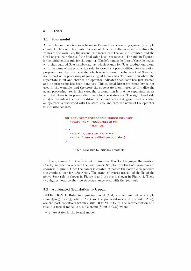
An simple Soar rule is shown below in Figure 4 for a counting system (examplecounter). The example counter consists of three rules: the first rule initializes thevalues of the variables, the second rule increments the value of counter, and thethird or goal rule checks if the final value has been reached. The rule in Figure 4is the initialization rule for the counter. The left hand side (lhs) of the rule beginswith the required Soar symbology sp, which stands for Soar production, alongwith the name of the production rule, followed by a pre-condition, for evaluationpurposes. Soar has a superstate, which is an internal mechanism that Soar canuse as part of its processing of goal-subgoal hierarchies. The condition where thesuperstate is nil and there is no operator indicates that Soar has just startedand no processing has been done yet. This subgoal hierarchy capability is notused in the example, and therefore the superstate is only used to initialize theagent processing. So, in this case, the precondition is that no superstate existsand that there is no pre-existing name for the state <s>. The right hand side(rhs) of the rule is the post condition, which indicates that, given the lhs is true,an operator is associated with the state <s> and that the name of the operatoris initialize counter.
Fig. 4. Soar rule to initialize a variable
The grammar for Soar is input to Another Tool for Language Recognition(Antlr), in order to generate the Soar parser. Scripts from the Soar grammar areshown in Figure 5. Once the parser is created, it parses the Soar file to generatethe graphical tree for a Soar rule. The graphical representation of the lhs of theabove Soar rule is shown in Figure 4 and the rhs is shown in Figure 5. Thesetwo figures describe the tree structure associated with the Soar rule.
5.2 Automated Translation to Uppaal
DEFINITION 1: Rules in cognitive model (CM) are represented as a tuplername(pre(), post()) where Pre() are the preconditions within a rule, Post()are the post conditions within a rule DEFINITION 2: The representation of arule in a formal model is a tuple tname(S,Init,E,G,U) where:
– S: are states in the formal model

LNCS 7
Fig. 5. Soar rule to initialize a variable
Fig. 6. Soar rule to initialize a variable
– Init: is initial state– E SxS: represents the edges for transition– G: represents the guard condition to be satisfied for the transition– U: represents the reset value or actions or updates
Algorithm:
1. Translate individual rules rname(pre(),post())(a) Identify name of the rule in CM translate to template or process or
component name in the formal environment (FE)(b) Precondition in CM translates to Guard in FE
i. Identify the variables in CM in pre() create global variables in FEii. Identify the logical comparisons, bindings in CMcreate similar logical
equations and assignments in FE(c) Postcondition translates to updates
i. Identify the variables and actions update the value of variables asthe actions
2. Generate scheduler schd(s,,e,g)(a) Identify the lifecycle of execution
i. Select rules based on satisfaction of pre conditionsii. Execute the rules
iii. Execute the goal test
One of the challenges in the translation is that Uppaal doesn’t support stringdata types. So any string comparison or pattern matching in Soar is translatedinto constant integers with the same name as the string in Soar.

8 LNCS
Translated Uppaal model The Soar model and its corresponding Uppaalmodel is as shown in Figure 7 below. The name of the Soar model counter∗propose∗initialize-counter in Uppaal is a template name. The preconditions in Soar statesthat no superstate exists and it does not have a name for the state s superstatenil and state sˆname is translated into a guard S Superstate == nil and S name== nil. The postcondition() state <s>ˆoperator<o> ˆname initialize-countergets translated into s operator o name = initialize counter. For the first rule an-other update s Superstate = not nil is automatically added as Soar implementsthat behavior implicitly.
Fig. 7. Soar rule to initialize a variable
The general rule scheduler implements the process lifecycle. It contains threestates: Start, Run and Check, as shown in 8. The transition from the startstate to run state executes the initialization step for the system by broadcastingRun Rule!. The initialization rule responds to it by initializing. The next step isexecution of the goal rule. If the goal is not satisfied, the scheduler transitionsfrom the Run to Check state on the guard condition, which is a negation of thegoal guard. Then from the check state, it transitions to Run state by sendingthe broadcast Run Rule! to which the relevant rules respond.
Fig. 8. Generic Scheduler
The scheduler is so designed such that it meets the following criteria:
– Configurable to meet different cognitive architecture– The satisfaction of the precondition selects the rule to be executed
LNCS 9
– Tests the goal condition to see if problem is complete
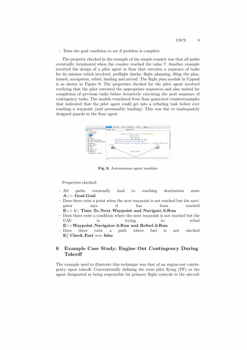
The property checked in the example of the simple counter was that all pathseventually terminated when the counter reached the value 7. Another exampleinvolved the design of a pilot agent in Soar that executes a sequence of tasksfor its mission which involved: preflight checks, flight planning, filing the plan,launch, navigation, refuel, landing and arrival. The flight plan module in Uppaalis as shown in Figure 9. The properties checked for the pilot agent involvedverifying that the pilot executed the appropriate sequences and also waited forcompletion of previous tasks before iteratively executing the next sequence ofcontingency tasks. The models translated from Soar generated counterexamplesthat indicated that the pilot agent could get into a refueling task before everreaching a waypoint (and presumably landing). This was due to inadequatelydesigned guards in the Soar agent.
Fig. 9. Autonomous agent modules
Properties checked:
– All paths eventually lead to reaching destination stateA<> Goal.Goal
– Does there exist a point when the next waypoint is not reached but the navi-gator says it has been reachedE<> t< Time To Next Waypoint and Navigate 0.Run
– Does there exist a condition where the next waypoint is not reached but theUAV is trying to refuelE<>Waypoint Navigator 0.Run and Refuel 0.Run
– Does there exist a path where fuel is not checkedE[] Check Fuel == false
6 Example Case Study: Engine Out Contingency DuringTakeoff
The example used to illustrate this technique was that of an engine-out contin-gency upon takeoff. Conventionally defining the term pilot flying (PF) as theagent designated as being responsible for primary flight controls in the aircraft

10 LNCS
(e.g., stick and surface inputs), and pilot not flying (PNF) as the agent not re-sponsible for primary flight controls, has the Soar agent assuming the role ofpilot not flying for this example. Thus, the Soar agent monitors procedure exe-cution for off nominal or contingency situations, as well as performs secondaryactuation tasks, similar to those performed by a copilot. However, it is importantto note that the human pilot is always ultimately responsible for the overall safeexecution of the flight [15].
For illustrative purposes, consider the scenario of a large cargo aircraft (suchas a Boeing 737) during takeoff which experiences an engine failure, wherebythe engine is delivering insufficient power after the aircraft brakes have beenreleased, but before the aircraft takeoff has been successfully completed. Priorto takeoff, the speed V 1 is calculated, which is defined by the FAA as ”themaximum speed in the takeoff at which the pilot must take the first action (e.g.,apply brakes, reduce thrust, deploy speed brakes) to stop the airplane withinthe accelerate-stop distance [16]. Thus, V 1 is a critical engine failure recognitionspeed, and can be used to determine whether or not the takeoff will continue,or result in a rejected takeoff (RTO). V 1 is dependent of factors such as aircraftweight, runway length, wing flap setting, engine thrust used and runway surfacecontamination. If the takeoff is aborted after the aircraft has reached V 1, thiswill likely result in a runway overrun, that is, the aircraft will stop at a point inexcess of the runway. Thus, V 1 is also seen as the speed beyond which the takeoffshould continue: the engine failure is then handled as an airborne emergency.
Prior to the takeoff procedure, a minimum of one person qualified to operateaircraft engines must be seated in a pilot’s seat when an aircraft engine is started,or running. Prior to taking the active runway for takeoff, the PF performs thefollowing actions, and briefs the PNF with respect to:
1. special factors influencing this takeoff (wet runway, anti-icing requirements,crosswind, deviations from the norm, etc.),
2. verification of airspeed settings (bugs) and power settings,3. verification of navigation equipment setup,4. verification of initial flight clearance (headings, altitudes, etc.), and5. review of the emergency return plan.
Thus, there must be a shared situation awareness regarding the contingencyplan at this point. In this standard briefing of the emergency return plan, theissue of engine failure is discussed. For takeoffs that experience any warning lightor reason before 80 Knots-Indicated-Airspeed (KIAS), the takeoff is aborted [17].After exceeding this lower threshold, but before attaining V 1, the takeoff is onlyaborted in the case of engine fire or failure, thrust reverser deployment, aircraftcontrol problems and warning conditions.
A conventional takeoff, whereby two humans fill the roles of the pilot flyingand pilot not flying proceeds as follows. Both pilots review any changes in theATC clearance prior to initiating the Before Takeoff (BT) checklist. All BeforeTakeoff checklist items must be completed before the takeoff roll commences.Once the checklist is completed, the following tasks are performed (see Table1 below). Note that the aircraft parking brake must be released on the active

LNCS 11
Fig. 10. Nominal Takeoff Procedure [17]
runway, and that the takeoff power (approximately 95 % N1, which is the revo-lutions per minute of the low pressure spool of the engine) must be set prior toattaining 60 KIAS.
During the Takeoff procedure, the PF and PNF perform the following se-quential actions described in Figure 10, often waiting for a task initiation cuethat comes from one another.
It can be seen that there is a great deal of interplay between the PF andPNF, especially in terms of affirming tasks and settings through callouts. Thesecallouts also serve to initiate the subsequent task in the procedure. Thus, anytasks that are delegated to an automated PNF, performing the copilot role, mustmimic this annunciation structure, in order to preserve situation awareness inthe cockpit, and foster teamwork in the human-automation crew. Now, in thecase of an engine failure at a speed of less than V1, but above the lower thresholdspeed of 80 kts, the actions shown in Figure 11 are taken.
Note that the contingency procedure is imbedded in the nominal procedure,and thus must be called from the nominal procedure.

12 LNCS
Fig. 11. Contingency Procedure For Engine Out on Takeoff [17]
6.1 Simulation and Experimentation with the Autonomous PilotAgent
To test the Autonomous Pilot Agent in a number of different scenarios, weconnected the commercial X-plane aircraft simulation [18] with a shim that readsthe relevant aircraft state variables (e.g., speed, altitude, attitude, position) andinjects them into Soar’s working memory. The rules for normal takeoff or engineout takeoff monitor the state of working memory to ensure that the appropriateactions are taken when conditions warrant it. Figure 12 shows the connection

LNCS 13
between the aircraft state variables and the Java-based Soar Autonomous PilotAgent
Fig. 12. Block diagram of the Simulation configuration
6.2 Formal Verification of the Autonomous Pilot Agent
The Soar rules for the autonomous agent that modeled the procedures followedby a copilot were translated into Uppaal. The rules executed based on inputsreceived from the flight simulator; this necessitated the creation of inputs suchas airspeed. In order to provide changes to the airspeed, a new input templatewas created in which the airspeed was updated at every step of execution. Thiswas followed by proving properties such as:
– airspeed greater than 80 is followed by applying rule for airspeed aliveR1 state io input link flightdata airspeed == 80 −− >state operator name == callaa
– All paths eventually lead to calling out Airspeed AliveR2 A<> state operator name == callaa
– All paths eventually lead to calling out rotateR3 A<> state operator name == callrotate

14 LNCS
While attempting to formally verify the above properties in Uppaal, we en-countered an out of range exception, as shown in Figure 13. This error was gen-erated as follows: While Soar is executing in a busy waiting state, it is updatinga counter variable without any bounds. It was never captured in the Soar envi-ronment, as events always occurred in the environment before the variable wouldoverflow. But this unbounded variable overflow was captured while proving theproperty R1 in Uppaal. Hence, in periods where no events are taking place, itis possible for the copilot agent to time out, in some respects. Thus, translationof these rules provide a way for understanding these cognitive environments fordesigning safety critical autonomous agents.
Fig. 13. Error
7 Conclusion and Future work
This research shows a method for the formal verification of intelligent agentsdesigned with cognitive architectures that implement collaborative interactionsbetween humans and autonomous systems. We have successfully developed anautomated translator that translates a Soar agent into a formally verifiable Up-paal model. This enables formal verification of models developed in Soar. Weplan to extend the translation to handle other constructs in Soar. This approachcan be extended to the verification of other cognitive architectures.
References
1. Schmerl B. Aldrich J. Garlan D. Kazman R. and Yan Y. Discovering architecturesfrom running systems. IEEE Transactions on Software Engineering, 32(7), 2006.

LNCS 15
2. Garlan D. Cheng S. Huang A. Schmerl B. and Steenkiste P. Rainbow: Architecture-based self adaptation with reusable infrastructure. IEEE Computer, 37(10), 2004.
3. Topcu U. Wen M., Ehlers R. Correct-by-synthesis reinforcement learning with tem-poral logic constraints. IEEE/RSJ International Conference on Intelligent Robotsand Systems, 2015.
4. Spoletini P. Sharifloo A.M. Lover: Light-weight formal verification of adaptivesystems at run time. Lecture Notes in Computer Science, 7684:170–187, 2013.
5. J.E. Laird. The SOAR Cognitive Architecture. MIT Press, 2012.6. John R. Anderson, Michael Matessa, and Christian Lebiere. Act-r: A theory of
higher level cognition and its relation to visual attention. Hum.-Comput. Interact.,12(4):439–462, December 1997.
7. M.M. Carvalho, T.C. Eskridge, L. Bunch, A. Dalton, R. Hoffman, J.M. Bradshaw,P.J. Feltovich, D. Kidwell, and T. Shanklin. Mtc2: A command and control frame-work for moving target defense and cyber resilience, 2013.
8. Marco Carvalho. Resilient command and control infrastructures for cyber opera-tions. In Proceedings of the 2015 IEEE/ACM 10th International Symposium onSoftware Engineering for Adaptive and Self-Managing Systems, SEAMS ’15, pages97–, Washington, DC, USA, 2015. IEEE Computer Society.
9. A. Granados and M.M. Carvalho. Overview of rails. Technical report, FloridaInstitute of Technology, 2015.
10. T.C. Eskridge, M.M. Carvalho, S. Bhattacharyya, and T. Vogl. Verifiable auton-omy final report. Technical report, Florida Institute of Technology and RockwellCollins, 2015.
11. Allen Newell, John C. Shaw, and Herbert A. Simon. Report on a general problem-solving program. In Proceedings of the International Conference on InformationProcessing, pages 256–264, 1959.
12. Bruce G. Buchanan and Edward H. Shortliffe. Rule Based Expert Systems: TheMycin Experiments of the Stanford Heuristic Programming Project (The Addison-Wesley Series in Artificial Intelligence). Addison-Wesley Longman Publishing Co.,Inc., Boston, MA, USA, 1984.
13. R.L. Sutton & B. Barto. Reinforcement Learning. MIT Press, 2008.14. T.C. Eskridge and M.M. Carvalho. Automated pilot model (apm) final report.
Technical report, Florida Institute of Technology, 2015.15. Natasha A. Neogi. Capturing safety requirements to enable effective task allocation
between humans and automaton in increasingly autonomous systems. In Proceed-ings of the AIAA Aviation Forum. 16th AIAA Aviation Technology, Integration,and Operations Conference, 7 2016. AIAA 2016-3594.
16. Code of Federal Regulations. Title 14 aeronautics and space chapter 1 definitionsand general requirements. Federal Register, 5 1962. http://www.ecfr.gov/cgi-bin/text.
17. The Boeing Company. Boeing 737 pilots operating handbook. Continental Airlines,11 2002. http://air.felisnox.com/view.php?name=737.pdf.
18. Official x-plane website, http://www.x-plane.com, 2016.