formal approaches to critical systems development: a case...
TRANSCRIPT
Universidade do MinhoDepartamento de Informatica
Ricardo Jorge Cantador Romano
Formal approaches to critical systemsdevelopment: a case study using SPARK
Mestrado em Engenharia Informatica
Trabalho efetuado sob a orientacao doProfessor Doutor Manuel Alcino Cunha
Outubro de 2011

ii
Acknowledgements
First of all, I would like to extend my sincere appreciation to Prof. Alcino Cunha for
having made himself available to supervise this dissertation. His commitment, willing-
ness and surgical comments were of most value and essential for the completion of this
work.
Part of this work was elaborated at Critical Software company, and hence I’m grateful
for the excellent human and logistic conditions provided. I’d like to thank all the people
the good atmosphere and the permanent contagious good mood, it was indeed extremely
rewarding working in such a friendly environment. In particular, I want to express my
gratitude to my local supervisor and friend, Jose Faria, for always being available to give
me a hand; also, to Andre and Pedro - the FM crew - who were authentic companions
of work and leisure, and to Pedrosa who devoted much of his time to many lively and
fruitful discussions.
To all the inspiring lecturers I had throughout my academic walk, in particular to Abel
Gomes, Antonio Sousa, Antonio Nestor, Gael Dias, Hugo Proenca, Jose Creissac, Jose
Nuno Oliveira, Luıs Alexandre, Luıs Barbosa, Paulo Moura, Sara Madeira. A special
reference must go to Simao Melo de Sousa for both introducing to me the formal “stuff”
and his friendship along the past few years.
To my friends, Diana, Eduardo, Flavio, and Marco, I know I don’t see you as often as
I’d like to, but I’m pretty much sure you’re always out there helping me out to keep
myself sane.
To my beloved family, my parents, Joao and Esperanca, my aunts, Cilinha and Helena,
and my grandfather “Amendoim” for all their support, confidence deposited on me, and
for so strongly encouraging me.“Muito obrigado, devo-vos tudo!”
To Sara, my half-orange, for all her love and total dedication, and to my adoptive family,
Maria Manuel, dona Mimi, Pim Preta, and Ze Paulo for putting up with me so happily
in recent times. A special word to sr. Ze for his friendship and wise advices.
During the elaboration of this work many other people have supported me either directly
or indirectly. Unfortunately I’m not able to mention everyone in here, but still I’m also
grateful to all of them.
iii

iv
Abstract
Formal approaches to critical systems development: a case study
using SPARK
Formal methods comprise a wide set of languages, technologies and tools based on
mathematics (logic, set theory) for specification, development and validation of software
systems. In some domains, its use is mandatory for certification of critical software
components requiring high assurance levels [1, 2].
In this context, the aim of this work is to evaluate, in practice and using SPARK
[3], the usage of formal methods, namely the ”Correctness by Construction” paradigm
[4], in the development of critical systems. SPARK is a subset of Ada language that
uses annotations (contracts), in the form of Ada comments, which describe the desired
behavior of the component.
Our case study is a microkernel of a real-time operating system based on MILS (Multiple
Independent Levels of Security/Safety) architecture [5]. It was formally developed in an
attempt to cover the security requirements imposed by the highest levels of certification.
v

vi

Resumo
Formal approaches to critical systems development: a case study
using SPARK
(Desenvolvimento formal de sistemas crıticos: caso de estudo
usando SPARK)
Os metodos formais agregam todo um conjunto de linguagens, tecnologias e ferramentas
baseadas em matematica (logica, teoria de conjuntos) para a especificacao, desenvolvi-
mento e validacao de sistemas de software. A sua utilizacao e, em certos domınios,
inclusivamente obrigatoria para a certificacao de componentes de software crıtico se-
gundo os nıveis mais elevados de seguranca [1, 2].
Neste contexto, pretende-se com este trabalho avaliar em termos praticos e com o uso do
SPARK [3], a utilizacao dos metodos formais, nomeadamente o paradigma ”Correctness
by Construction” [4], no desenvolvimento de sistemas crıticos. A linguagem SPARK
consiste num subconjunto da linguagem Ada, que utiliza anotacoes (contractos), sob a
forma de comentarios em Ada, que descrevem o comportamento desejado do componente.
O caso de estudo consiste num microkernel de um sistema operativo de tempo real
baseado na arquitectura MILS (Multiple Independent Levels of Security/Safety) [5]. A
sua modelacao procurou cobrir os requisitos de seguranca impostos pelos mais elevados
nıveis de certificacao.
vii

viii
Contents
Abstract v
Resumo vii
List of Figures xii
List of Tables xiii
Code Listings xv
1 Introduction 1
1.1 Critical systems . . . . . . . . . . . . . . . . . . . . . . . . . . . . . . . . . 1
1.2 Operating system . . . . . . . . . . . . . . . . . . . . . . . . . . . . . . . . 2
1.3 Our aim and objectives . . . . . . . . . . . . . . . . . . . . . . . . . . . . 3
1.4 Contribution . . . . . . . . . . . . . . . . . . . . . . . . . . . . . . . . . . 3
1.5 Dissertation outline . . . . . . . . . . . . . . . . . . . . . . . . . . . . . . . 4
2 High assurance software development with SPARK 5
2.1 Formal methods . . . . . . . . . . . . . . . . . . . . . . . . . . . . . . . . 5
2.1.1 Classical . . . . . . . . . . . . . . . . . . . . . . . . . . . . . . . . . 8
2.1.2 Lightweight . . . . . . . . . . . . . . . . . . . . . . . . . . . . . . . 10
2.1.3 Directed to the code . . . . . . . . . . . . . . . . . . . . . . . . . . 11
2.2 SPARK overview . . . . . . . . . . . . . . . . . . . . . . . . . . . . . . . . 12
2.3 Development methodology . . . . . . . . . . . . . . . . . . . . . . . . . . . 19
2.3.1 Correctness by construction . . . . . . . . . . . . . . . . . . . . . . 20
2.3.1.1 Formal specification . . . . . . . . . . . . . . . . . . . . . 21
2.3.1.2 INFORMED . . . . . . . . . . . . . . . . . . . . . . . . . 23
2.3.2 Tools . . . . . . . . . . . . . . . . . . . . . . . . . . . . . . . . . . 26
2.4 Summary . . . . . . . . . . . . . . . . . . . . . . . . . . . . . . . . . . . . 27
3 Case study: a secure partitioning microkernel 29
3.1 Microkernel . . . . . . . . . . . . . . . . . . . . . . . . . . . . . . . . . . . 31
ix

Contents x
3.2 Separation kernel . . . . . . . . . . . . . . . . . . . . . . . . . . . . . . . . 32
3.2.1 Spatial partitioning . . . . . . . . . . . . . . . . . . . . . . . . . . 33
3.2.2 Temporal partitioning . . . . . . . . . . . . . . . . . . . . . . . . . 34
3.3 Security partitioning and MILS . . . . . . . . . . . . . . . . . . . . . . . . 34
3.4 Summary . . . . . . . . . . . . . . . . . . . . . . . . . . . . . . . . . . . . 39
4 Formal approaches to kernel development 40
4.1 Traditional kernels . . . . . . . . . . . . . . . . . . . . . . . . . . . . . . . 41
4.2 Separation kernels . . . . . . . . . . . . . . . . . . . . . . . . . . . . . . . 49
4.3 Tokeneer project . . . . . . . . . . . . . . . . . . . . . . . . . . . . . . . . 52
4.4 Summary . . . . . . . . . . . . . . . . . . . . . . . . . . . . . . . . . . . . 53
5 Implementation 54
5.1 Formal specification/design . . . . . . . . . . . . . . . . . . . . . . . . . . 55
5.2 INFORMED in practice . . . . . . . . . . . . . . . . . . . . . . . . . . . . 58
5.2.1 Identification of the system boundary, inputs and outputs . . . . . 58
5.2.2 Identification of the SPARK boundary . . . . . . . . . . . . . . . . 59
5.2.3 Identification and localization of system states . . . . . . . . . . . 59
5.3 Handling initialization of state . . . . . . . . . . . . . . . . . . . . . . . . 61
5.4 Handling secondary requirements . . . . . . . . . . . . . . . . . . . . . . . 61
5.5 Implementing the internal behavior of components . . . . . . . . . . . . . 62
5.6 Other issues . . . . . . . . . . . . . . . . . . . . . . . . . . . . . . . . . . . 73
6 Conclusions 78
6.1 Main aim and objectives . . . . . . . . . . . . . . . . . . . . . . . . . . . . 78
6.2 Contributions . . . . . . . . . . . . . . . . . . . . . . . . . . . . . . . . . . 81
6.3 Future work . . . . . . . . . . . . . . . . . . . . . . . . . . . . . . . . . . . 82
Bibliography 83
A Requirements 97
A.1 Configuration management system requirements . . . . . . . . . . . . . . 98
A.2 System error and faults requirements . . . . . . . . . . . . . . . . . . . . . 100
A.3 System table requirements . . . . . . . . . . . . . . . . . . . . . . . . . . . 101
A.4 Partition requirements . . . . . . . . . . . . . . . . . . . . . . . . . . . . . 102
A.5 Process requirements . . . . . . . . . . . . . . . . . . . . . . . . . . . . . . 105
A.6 Partition information flow requirements . . . . . . . . . . . . . . . . . . . 107
B Z models 109
B.1 Types . . . . . . . . . . . . . . . . . . . . . . . . . . . . . . . . . . . . . . 109
B.1.1 Memory . . . . . . . . . . . . . . . . . . . . . . . . . . . . . . . . . 109
B.1.2 Kernel . . . . . . . . . . . . . . . . . . . . . . . . . . . . . . . . . . 110
Contents xi
B.1.3 Partition . . . . . . . . . . . . . . . . . . . . . . . . . . . . . . . . 111
B.1.4 Communication . . . . . . . . . . . . . . . . . . . . . . . . . . . . . 112
B.2 System state . . . . . . . . . . . . . . . . . . . . . . . . . . . . . . . . . . 113
B.2.1 Initialization operations . . . . . . . . . . . . . . . . . . . . . . . . 115
B.2.2 Partiton operations . . . . . . . . . . . . . . . . . . . . . . . . . . . 118
B.2.3 User operations . . . . . . . . . . . . . . . . . . . . . . . . . . . . . 123
B.2.4 Kernel operations . . . . . . . . . . . . . . . . . . . . . . . . . . . . 127
C SPARK packages 131
C.1 DefaultValues . . . . . . . . . . . . . . . . . . . . . . . . . . . . . . . . . . 131
C.2 PartitionTypes . . . . . . . . . . . . . . . . . . . . . . . . . . . . . . . . . 131
C.3 PRT . . . . . . . . . . . . . . . . . . . . . . . . . . . . . . . . . . . . . . . 133
C.4 TablesTypes . . . . . . . . . . . . . . . . . . . . . . . . . . . . . . . . . . . 135
C.5 HardwareTypes . . . . . . . . . . . . . . . . . . . . . . . . . . . . . . . . . 136
C.6 ErrorTypes . . . . . . . . . . . . . . . . . . . . . . . . . . . . . . . . . . . 137
C.7 SEF . . . . . . . . . . . . . . . . . . . . . . . . . . . . . . . . . . . . . . . 137
C.8 Hardware . . . . . . . . . . . . . . . . . . . . . . . . . . . . . . . . . . . . 138
C.9 CMS . . . . . . . . . . . . . . . . . . . . . . . . . . . . . . . . . . . . . . . 140
C.10 SYT . . . . . . . . . . . . . . . . . . . . . . . . . . . . . . . . . . . . . . . 143
C.11 ConfigValues . . . . . . . . . . . . . . . . . . . . . . . . . . . . . . . . . . 156
D Example of a configuration file 179
List of Figures
2.1 Ada and SPARK . . . . . . . . . . . . . . . . . . . . . . . . . . . . . . . . 14
2.2 INFORMED notation . . . . . . . . . . . . . . . . . . . . . . . . . . . . . 24
2.3 Identification of the system boundary . . . . . . . . . . . . . . . . . . . . 25
2.4 Identification of the SPARK boundary . . . . . . . . . . . . . . . . . . . . 25
3.1 Monolithic kernel and microkernel . . . . . . . . . . . . . . . . . . . . . . 31
3.2 Two level scheduler . . . . . . . . . . . . . . . . . . . . . . . . . . . . . . . 35
3.3 Multiple Independent Levels of Safety/Security (MILS) architecture . . . 36
3.4 Inter-partition communication . . . . . . . . . . . . . . . . . . . . . . . . . 37
3.5 Policies of communication . . . . . . . . . . . . . . . . . . . . . . . . . . . 38
5.1 Implementation steps . . . . . . . . . . . . . . . . . . . . . . . . . . . . . . 55
5.2 SPARK system boundary . . . . . . . . . . . . . . . . . . . . . . . . . . . 59
5.3 Localization of state . . . . . . . . . . . . . . . . . . . . . . . . . . . . . . 61
5.4 A possible state of communication memory . . . . . . . . . . . . . . . . . 75
5.5 POGS summary . . . . . . . . . . . . . . . . . . . . . . . . . . . . . . . . 77
xii
List of Tables
2.1 Time, cost and quality with use of Formal Methods . . . . . . . . . . . . . 6
4.1 Traditional kernels verification . . . . . . . . . . . . . . . . . . . . . . . . 49
5.1 System boundary, inputs and outputs . . . . . . . . . . . . . . . . . . . . 58
5.2 State identification . . . . . . . . . . . . . . . . . . . . . . . . . . . . . . . 60
5.3 PartitionTypes package . . . . . . . . . . . . . . . . . . . . . . . . . . . . 63
5.4 PRT package . . . . . . . . . . . . . . . . . . . . . . . . . . . . . . . . . . 64
5.5 TablesTypes package . . . . . . . . . . . . . . . . . . . . . . . . . . . . . . 66
5.6 ErrorTypes package . . . . . . . . . . . . . . . . . . . . . . . . . . . . . . 68
5.7 SEF package . . . . . . . . . . . . . . . . . . . . . . . . . . . . . . . . . . 69
5.8 Hardware package . . . . . . . . . . . . . . . . . . . . . . . . . . . . . . . 70
5.9 CMS package . . . . . . . . . . . . . . . . . . . . . . . . . . . . . . . . . . 71
5.10 SYT package . . . . . . . . . . . . . . . . . . . . . . . . . . . . . . . . . . 72
5.11 Configuration file format . . . . . . . . . . . . . . . . . . . . . . . . . . . . 74
A.1 Requirement format . . . . . . . . . . . . . . . . . . . . . . . . . . . . . . 98
A.2 CMS requirement # 01 . . . . . . . . . . . . . . . . . . . . . . . . . . . . 98
A.3 CMS requirement # 02 . . . . . . . . . . . . . . . . . . . . . . . . . . . . 99
A.4 CMS requirement # 03 . . . . . . . . . . . . . . . . . . . . . . . . . . . . 99
A.5 CMS requirement # 04 . . . . . . . . . . . . . . . . . . . . . . . . . . . . 99
A.6 CMS requirement # 05 . . . . . . . . . . . . . . . . . . . . . . . . . . . . 100
A.7 SEF requirement # 01 . . . . . . . . . . . . . . . . . . . . . . . . . . . . . 100
A.8 SEF requirement # 02 . . . . . . . . . . . . . . . . . . . . . . . . . . . . . 100
A.9 SYT requirement # 01 . . . . . . . . . . . . . . . . . . . . . . . . . . . . . 101
A.10 SYT requirement # 02 . . . . . . . . . . . . . . . . . . . . . . . . . . . . . 101
A.11 SYT requirement # 03 . . . . . . . . . . . . . . . . . . . . . . . . . . . . . 101
A.12 PRT requirement # 01 . . . . . . . . . . . . . . . . . . . . . . . . . . . . . 102
A.13 PRT requirement # 02 . . . . . . . . . . . . . . . . . . . . . . . . . . . . . 102
A.14 PRT requirement # 03 . . . . . . . . . . . . . . . . . . . . . . . . . . . . . 102
A.15 PRT requirement # 04 . . . . . . . . . . . . . . . . . . . . . . . . . . . . . 103
A.16 PRT requirement # 05 . . . . . . . . . . . . . . . . . . . . . . . . . . . . . 103
A.17 PRT requirement # 06 . . . . . . . . . . . . . . . . . . . . . . . . . . . . . 103
A.18 PRT requirement # 07 . . . . . . . . . . . . . . . . . . . . . . . . . . . . . 104
xiii
List of Tables xiv
A.19 PRT requirement # 08 . . . . . . . . . . . . . . . . . . . . . . . . . . . . . 104
A.20 PRT requirement # 09 . . . . . . . . . . . . . . . . . . . . . . . . . . . . . 104
A.21 PRT requirement # 10 . . . . . . . . . . . . . . . . . . . . . . . . . . . . . 105
A.22 PRT requirement # 11 . . . . . . . . . . . . . . . . . . . . . . . . . . . . . 105
A.23 PRC requirement # 01 . . . . . . . . . . . . . . . . . . . . . . . . . . . . . 105
A.24 PRC requirement # 02 . . . . . . . . . . . . . . . . . . . . . . . . . . . . . 105
A.25 PRC requirement # 03 . . . . . . . . . . . . . . . . . . . . . . . . . . . . . 106
A.26 PRC requirement # 04 . . . . . . . . . . . . . . . . . . . . . . . . . . . . . 106
A.27 PRC requirement # 05 . . . . . . . . . . . . . . . . . . . . . . . . . . . . . 106
A.28 PIFP requirement # 01 . . . . . . . . . . . . . . . . . . . . . . . . . . . . 107
A.29 PIFP requirement # 02 . . . . . . . . . . . . . . . . . . . . . . . . . . . . 107
A.30 PIFP requirement # 03 . . . . . . . . . . . . . . . . . . . . . . . . . . . . 107
A.31 PIFP requirement # 04 . . . . . . . . . . . . . . . . . . . . . . . . . . . . 108
A.32 PIFP requirement # 05 . . . . . . . . . . . . . . . . . . . . . . . . . . . . 108
A.33 PIFP requirement # 06 . . . . . . . . . . . . . . . . . . . . . . . . . . . . 108

Code Listings
2.1 Stack specification package . . . . . . . . . . . . . . . . . . . . . . . . . . 15
2.2 Stack body package . . . . . . . . . . . . . . . . . . . . . . . . . . . . . . . 16
2.3 Push and Pop procedures with proof annotations . . . . . . . . . . . . . . 18
5.1 PRT specification package (GetID, GetDuration and GetPartitionModefunctions) . . . . . . . . . . . . . . . . . . . . . . . . . . . . . . . . . . . . 64
5.2 PRT specification package (SetPartitionMode procedure) . . . . . . . . . 65
5.3 PRT specification package (Init procedure) . . . . . . . . . . . . . . . . . 65
5.4 PRT specification package (ClearCommunicationList procedure) . . . . . 66
5.5 TablesTypes specification package . . . . . . . . . . . . . . . . . . . . . . 67
5.6 SEF specification package . . . . . . . . . . . . . . . . . . . . . . . . . . . 70
5.7 Hardware specification package (CanAllocate function and AllocBlock,Init procedures) . . . . . . . . . . . . . . . . . . . . . . . . . . . . . . . . . 71
C.1 DefaultValues package . . . . . . . . . . . . . . . . . . . . . . . . . . . . . 131
C.2 PartitionTypes package . . . . . . . . . . . . . . . . . . . . . . . . . . . . 131
C.3 PRT specification package . . . . . . . . . . . . . . . . . . . . . . . . . . . 133
C.4 PRT body package . . . . . . . . . . . . . . . . . . . . . . . . . . . . . . . 134
C.5 TablesTypes package . . . . . . . . . . . . . . . . . . . . . . . . . . . . . . 135
C.6 HardwareTypes package . . . . . . . . . . . . . . . . . . . . . . . . . . . . 136
C.7 ErrorTypes package . . . . . . . . . . . . . . . . . . . . . . . . . . . . . . 137
C.8 SEF specification package . . . . . . . . . . . . . . . . . . . . . . . . . . . 137
C.9 SEF body package . . . . . . . . . . . . . . . . . . . . . . . . . . . . . . . 137
C.10 Hardware specification package . . . . . . . . . . . . . . . . . . . . . . . . 138
C.11 Hardware body package . . . . . . . . . . . . . . . . . . . . . . . . . . . . 138
C.12 CMS specification package . . . . . . . . . . . . . . . . . . . . . . . . . . . 140
C.13 CMS body package . . . . . . . . . . . . . . . . . . . . . . . . . . . . . . . 142
C.14 SYT specification package . . . . . . . . . . . . . . . . . . . . . . . . . . . 143
C.15 SYT body package . . . . . . . . . . . . . . . . . . . . . . . . . . . . . . . 146
C.16 ConfigValues specification package . . . . . . . . . . . . . . . . . . . . . . 156
C.17 ConfigValues body package . . . . . . . . . . . . . . . . . . . . . . . . . . 158
xv
Chapter 1
Introduction
In our modern society, software is everywhere. Examples of systems controlled by soft-
ware can be found in sectors like aerospace, railway, banking, medical, energy, defense,
among others. Many of these systems are critical systems whose failures threaten hu-
man lives. So, the correction of this software is a demand. Any error on safety critical
systems can have catastrophic consequences, can originate loss of life or damage to the
environment. On security systems an error may be equally devastator, as in the case of
loss of national security or commercial reputation.
1.1 Critical systems
Safety critical and secure systems must be designed with great care, and the correctness
of the software is highly important to guarantee their integrity. This kind of systems
have a trusted set that consists in the hardware and software required to ensure the
system security policy. These components, and the software is no exception, have some
properties that are demanded for the behavior of the system to be considered safe and
secure. In software, wheres the scope of this work is, these properties can be expressed
as predicates that must be satisfied and maintained while the system works even with
the inputs/outputs interferences.
For example, an aircraft cabin pressure control is of vital importance to the passengers
and crew. This system ensures that the air pressure is maintained within predefined
limits, taking a special care in the rapid changes of pressure to ensure occupant comfort.
1
Chapter 1. Introduction 2
It also protects the airplane itself against problems that might be caused by high dif-
ference between internal and external pressure. System sensors read the pressure value
and pass those data on to the controllers to verify the need to increase or decrease the
pressure inside the plane. This management should be done within a set up time interval
to maintain the safety of occupants and the airplane itself. An aircraft cabin pressure
control helps to keep the plane in a safe state. Above 3000 meters a pressurization sys-
tem failure requires an emergency descent to 3000 meters for the availability of oxygen
to its occupants and hence for the masks to come out.
In this example, safety is defined with respect to occupants security and good condition
of airplane. The safety predicate for the software, besides of course that the system
must run always without errors, is the time that elapses between the inputs from the
sensors to the outputs of the actuators of the system that controls the air pressure. For
safety purposes, this predicate for the pressurization control software needs to increase or
decrease the pressure (to achieve safety values) inside of the aircraft at a range of initial
time set up beforehand. As mentioned above, a failure of the aircraft cabin pressure
control to be detected above 3000 meters requires a descent of the aircraft as well as the
triggering device that releases automatically oxygen masks for passengers. To control
all these devices and different associate systems we need an operating system (OS). The
OS allows all components to run and perform its tasks besides allowing communication
between them.
1.2 Operating system
Clearly the OS is a key component of the whole system, whose correctness and reliability
depends on the OS. So, the OS is part of the trusted set of the system. Yet these systems
with a security policy do not support the common OS (monolithic kernel), because they
can not deal with correctness, reliability, and security. The microkernels adapt better
to this type of systems due to the principles of least privilege and minimality used in
the architecture. However, in order to make a reliable microkernel, a correct design is
necessary and also a correct implementation of it. Those steps can be achieved with the
use of formal methods in order to be able to verify their accuracy. This is in fact the
main subject of this MSc work.
Chapter 1. Introduction 3
1.3 Our aim and objectives
The main aim of this dissertation is to study the usage of SPARK [3] language and its
associate methodology in systems development. Following a Correctness by Construction
(CbyC)-based methodology, it aims to confirm what was demonstrated by other authors
(including [6, 7]) concerning the possibility of developing systems able to achieve high
levels of certification. The CbyC methodology was used by Altran Praxis and was
more widely disseminated in the Tokeneer project [8]. This project was a collaboration
of Praxis and NSA (National Security Agency) to demonstrate that it is possible to
develop systems up to the level of rigor required by the highest standards of the Common
Criteria. In Chapter 4, we introduce the Tokeneer project in more detail.
Therefore, ultimately we sought to apply the Tokeneer project’s outcome in a different
context, which constituted our case study. A kernel is surely a key central part of a
system and therefore it was chosen to apply the methodology above. More specifically,
a secure partitioning microkernel - a kernel with partitioning and security properties
required for critical systems - was considered. Starting from a simplified but yet repre-
sentative set of functional requirements for this type of system, we planed to develop a
secure partitioning microkernel-based simulator using the CbyC development method.
In order to accomplish this, we identified the following steps to be performed:
• To investigate the system requirements;
• To use the Z notation to create a high level specification;
• To construct a design of the system with INFORMED process;
• To implement the system in SPARK;
• To verify the system using the SPARK Examiner toolset.
1.4 Contribution
We strongly believe that the work presented in this dissertation is a valid contribution in
order to obtain a software capable of achieving the highest levels of certification, which is
required when security systems are concerned. The subject under study is also of great
relevance since it is a microkernel-based approach, which is clearly the central defining
feature of an OS.

Chapter 1. Introduction 4
1.5 Dissertation outline
This dissertation is organized in six chapters. Chapter 1 introduces the main concepts
that are subject of study in this work. Chapter 2 gives a brief overview about software
engineering with formal methods and presents the SPARK language and the methodol-
ogy followed int the work. Chapter 3 presents the work that is to be developed, giving
an overview of what is a secure partitioning microkernel and the proposed solution.
Chapter 4 gives an overview about the state of the art involving formal verification
for kernels. Chapter 5 contains the development of the work, a formal model of the
secure partitioning microkernel followed the CbyC approach. Chapter 6 concludes this
dissertation by describing the most relevant conclusions of the work herein described.
Chapter 2
High assurance software
development with SPARK
In this chapter formal methods are reviewed. We separate them in three distinct cat-
egories: the classical approaches, the lightweight approaches, and the approaches more
directed to the code. We also introduce the SPARK language and the development
methodology that was used in this work.
2.1 Formal methods
Formal methods (FM) involve the application of mathematical techniques, most often
supported by development tools. They can be applied in different situations with system
models that specify every detail of the implementation or only the most abstract require-
ment, with different notations and different tools. FM are used in software specification
to obtain a precise statement of what the software does (its functionality), not concerned
about how to do it. They are also used in the implementation with the propose of code
verification.
Non safety-critical systems, normally use an informal method via some combination of
testing and inspections to verify the software with respect to functional requirements.
Failures that are not detected in these informal inspections are found later, with the
use of the software itself and with a huge cost associated. When speaking of software
5
Chapter 2. High assurance software development with SPARK 6
for critical systems, this kind of informal verification is inadequate and more rigorous
techniques are necessary. In some cases, the regulatory agencies are the ones that require
more rigorous methods, such as the use of FM.
There is a big difference in attitude with respect to FM. Generally speaking, FM are seen
as a key in academia; on the other hand, are seen as somewhat irrelevant in the industry,
with the exception of critical systems industry. Although there are some changes with
respect to greater acceptance and use of FM, there is still a long way to go to achieve a
general dissemination of their use in other areas beyond the critical areas.
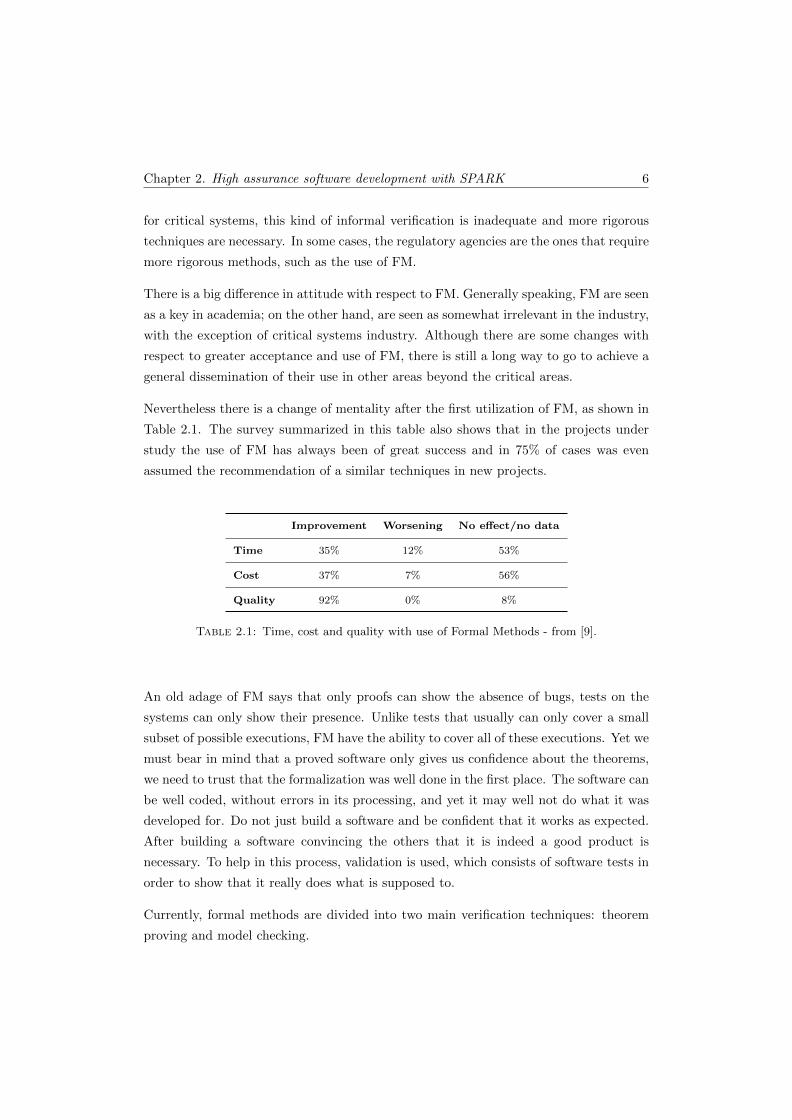
Nevertheless there is a change of mentality after the first utilization of FM, as shown in
Table 2.1. The survey summarized in this table also shows that in the projects under
study the use of FM has always been of great success and in 75% of cases was even
assumed the recommendation of a similar techniques in new projects.
Improvement Worsening No effect/no data
Time 35% 12% 53%
Cost 37% 7% 56%
Quality 92% 0% 8%
Table 2.1: Time, cost and quality with use of Formal Methods - from [9].
An old adage of FM says that only proofs can show the absence of bugs, tests on the
systems can only show their presence. Unlike tests that usually can only cover a small
subset of possible executions, FM have the ability to cover all of these executions. Yet we
must bear in mind that a proved software only gives us confidence about the theorems,
we need to trust that the formalization was well done in the first place. The software can
be well coded, without errors in its processing, and yet it may well not do what it was
developed for. Do not just build a software and be confident that it works as expected.
After building a software convincing the others that it is indeed a good product is
necessary. To help in this process, validation is used, which consists of software tests in
order to show that it really does what is supposed to.
Currently, formal methods are divided into two main verification techniques: theorem
proving and model checking.

Chapter 2. High assurance software development with SPARK 7
The theorem proving approach consists of the description of the desired system proper-
ties in a formal logic, with a set of axioms, pre- and post-conditions in order to build
a model. Secondly, a mathematical proof is conceived with the aim to ensure that the
model satisfies the desired properties. Although theorem provers have evolved signifi-
cantly, by removing some of the tedious processes of the proof, they still need human
intervention to guide the more complex proofs. This is a process that requires significant
knowledge and is seen as the disadvantage of theorem proving.
One way in order to facilitate the process, with the aim to automatically discharge more
proofs, can be achieved with tools that provide the best possible solution to discharge
the proof - as with in Frama-C [10], where the proof can be discharged in several different
provers in a manner that benefit from the different characteristics of each prover. This
allows that different parts of the program are proved with different provers.
On contrary, the model checking has a greater automatism, thus requiring less human
intervention. Typically, model checking works on a model that contains only the neces-
sary and relevant system properties. This is necessary because the accessible state space
of a model will be thoroughly explored to determine if the properties are maintained;
obviously, this space should not grow in an unnecessary manner. The size of state space
thus becomes a handicap in contrast to what happens in theorem proving where the
state space is not a problem - and indeed makes it effective in more complex systems
and in full functional correctness. Typically, in these systems with more complexity, the
model checking is only used to verify some specific properties, not the whole system.
Besides the verifications on a model, there are tools like SLAM [11] that work directly
on the code, but once again, the properties checked are simple and do not cover the
whole system. Unlike theorem provers, the model checking is more accessible for rela-
tively inexpert users. There have been major advances with regards to the state space
explosion problem, which makes the model checkers a very practical tool especially if
placed in a native way in the IDE commonly used by developers.
Some FM are presented below divided into three distinct classes: the classical ap-
proaches, the lightweight approaches, and the approaches more directed to the code.
The classical and the more directed to the code approaches comprise methods with the-
orem proving but provide simultaneously model checking. The lightweight approaches
comprise only the model checking method.
Chapter 2. High assurance software development with SPARK 8
2.1.1 Classical
This classification of classical FM refers to the traditional approaches, which invokes
set theory and first order logic. Therefore, the three main model-oriented FM [12] are
presented below: the Z notation, the B-Method and the VDM. These are also the most
popular formal software development methods [13].
• The Z (pronounced ”zed”) notation is a specification language based on set theory
and first order predicate calculus. It has been developed in the late 1970s, by
the Programming Research Group (PRG) at the Oxford University Computing
Laboratory (OUCL), inspired by a Jean-Raymond Abrial work. The notation
was defined formally by Spivey in 1988 [14]. In order to facilitate the specification
process, Z notation allows the decomposing of the system specification into smaller
components. The individual components are then combined at the end in order
to describe the entire system as a whole. Z models are usually accompanied by
a narrative in a common language that helps readers, writers and reviewers to
understand the models. An introduction to this notation can be found below in
section 2.3.1.1 - Formal specification.
The notation has a wide range of support tools1, some of them are described below:
– The Community Z Tools (CZT) project [16] is an open source project pro-
viding an integrated toolset to support Z notation;
– Fuzz [17] is a type checker created by Spivey for the Z language;
– ProofPower [18] is a suite of tools supporting specification and proof in Higher
Order Logic (HOL) and in the Z notation;
– ProZ [19] is an extension of the B-Method tool ProB, that offers some support
for model checking and for animating Z specifications;
– HOL-Z [20] is an interactive theorem prover for Z based on Isabelle/HOL.
• The B-Method [21] is a formal development methodology based on set theory with
first-order logic. It uses the abstract machine notation (AMN) as specification
language and allows progress from an initial high-level specification all the way to
the implementation via formal refinement. B-Method has been developed by Jean-
Raymond Abrial (the originator of Z notation). B-method has been successfully
1The reader is referred to the section on Z notation available from the Wiki, set up by JonathanBowen [15], were a more complete list of tools can be found.
Chapter 2. High assurance software development with SPARK 9
used in the development of many complex high integrity systems, as the driverless
metro line 14 in Paris [22] or the driverless shuttle for Paris-Roissy airport [23].
The main tools of B-Method are:
– The B-Toolkit [24], which is a set of integrated tools which fully supports the
B-Method for formal software development;
– Atelier B [25], which is the more complete tool for B-Method, include features
like type and static semantics checking, proof support and refinement;
– ProB [19], which is an animator and model checker for B-Method;
– The Rodin Platform [26] is an open source Eclipse-based IDE for Event-B
language. Event-B is an evolution of B-Method and one of the main reasons
for this evolution was simplicity [27].
• The Vienna Development Method (VDM) is a complete software development
method, whose features are modeling computing systems, analyzing models and
progressing to detailed design and coding. It has been developed in the IBM
Vienna Laboratory in the mid-1970s. VDM is a method which uses a specification
notation that is similar to Z. The first complete exposition of the notation and
method was made in [28]. The original VDM Specification Language (VDM-SL)
[29] was extended for VDM++ [30]. The main difference between VDM-SL and
VDM++ notations are the way in which structuring is dealt with. In VDM-SL
there is a conventional modular extension, whereas VDM++ has a traditional
object-oriented structuring mechanism with classes and multiple inheritance.
VDM has two main sets of support tools. They are:
– The VDMTools [31] is the leading commercial tool for VDM-SL and VDM++.
It supports syntax and type checking, includes a test coverage tool and also
includes automatic code generation;
– Overture [32] is an open source project that has the objective of developing
the next generation of open-source tools for VDM. In addition to support
VDM-SL and VDM++, these tools also offer support to VDM-RT (the new
extension of VDM that is concerned with real-time and distributed systems).
The Overture tools are written entirely in Java and build on top of the Eclipse
platform.
Chapter 2. High assurance software development with SPARK 10
2.1.2 Lightweight
Lightweight formal methods is a recent approach that combines the classical ideas of
a formal specification from methods like those presented above, and verification with
new automatic checking processes, usually for partial problems. They have the capacity
to yield results with a fast and easy application. They are usually applied with more
modest goals and the used tools require less specific knowledge to apply them. They can
be seen as a way of facilitating the incursion of the FM in the industry in general, because
they can be applied/added in the development cycle typically used in the company.
There are many works that use “heavyweight” methods in a light manner [33–36], i.e.
they only implement a piece of technology/methodology, or apply it to a single part of
the system. We do not present these methods in this section as they appear in sections
2.1.1 and 2.1.3. We give a special emphasis to model checking methods because their use
is often underestimated and people sometimes not perceive the potential and benefits
over standard tests. The model checker finds bugs in a more reliable way than normal
tests, since it verifies a state space with a much higher size.
Below are presented some of the lightweight formal methods commonly used:
• Alloy is a lightweight modeling language for software design. Alloy was devel-
oped at MIT by the Software Design Group under the guidance of Daniel Jackson
[37]. The language is strongly influenced by the Z specification language presented
above. The support tool is the Alloy Analyzer that provides a fully automatic
analysis and provides a visualizer that shows the solutions and counterexamples
that it finds.
• SPIN [38] is a popular model checker developed in 1980 at Bell Labs in the original
Unix group of the Computing Sciences Research Center. The formal models are
written in PROMELA (Process Meta Language). SPIN verifies the correctness
of distributed software models in a rigorous and mostly automated fashion and
provides support for linear temporal logic.
• UPPAAL [39] is a model checker developed in collaboration between the Depart-
ment of Information Technology at Uppsala University in Sweden, and the De-
partment of Computer Science at Aalborg University in Denmark. This tool is
indicated for real-time systems modeled as networks of timed automata. It enables
three model development stages: modeling, simulation/validation, and verification.
Chapter 2. High assurance software development with SPARK 11
• TLC [40] is a model checker and a simulator for specifications written in TLA+
[41]. TLA+ is a specification language based on TLA (Temporal Logic of Actions)
[42] and was developed by the Microsoft research center. It is particularly useful
for describing concurrent and distributed systems. The TLC model checker is
included in the main tool for TLA+, the TLA Toolbox [43].
2.1.3 Directed to the code
This section focuses on the methods directed to the source code. In these methods, as
first suggested by Hoare logic [44], assertions are used in the program code. The design-
by-contract2 is one of the code oriented formal methodologies. It receives highlight in
this section because part of this work uses the methodology.
The term Design by Contract was originally introduced by Bertrand Meyer [45]. He was
the founder of Eiffel [46, 47], the first language that supports the paradigm. Beyond
Eiffel, there are other languages that support also Design by Contract such as Spec# [48],
SPARK [3] (which will be used in this work), C with ACSL3 [49] and tools like frama-C
[10], Java with Java Modeling Language(JML) [50] or ESC/Java2 [51] and many more.
As defined in [52], a contract is a technique for specifying the obligations of participat-
ing objects. It is intended to formalize the collaboration and behavioral relationships
between objects in a non-ambiguous manner. A contract therefore defines communicat-
ing participants and their contractual obligations. The contractual obligations not only
comprise traditional type signatures but also capture behavioral dependencies. With
the help of formal verification methods, it is possible to prove that software behavior is
correct in respect to these specifications.
The contracts must be written in a previous stage than that of the code since they are
more abstract. This gives us a first model of the application design. The improvement
of this first approach is accomplished by refining the contracts. We are only ready
to move on to the code implementation when the architecture is stable. Contracts
enable the storage of details and assumptions towards the documentation of software
components and API usage. It avoids for example the constant check of arguments in
operations. Moreover, contracts are also important during the coding process to inform
the programmer what he/she is supposed to do.
2Design-by-Contract is a trademark of Interactive Software Engineering Inc.3ANSI/ISO C Specification Language.
Chapter 2. High assurance software development with SPARK 12
The usefulness of contracts depends naturally on their quality and pertinence. In the
next sections we will try to show how this can be achieved.
2.2 SPARK overview
SPARK consists of a high level programming language. It has been conceived for writing
software for high integrity applications, where it is mandatory that the program is well
written (without errors). High integrity applications include both safety and security.
Safety critical applications are usually defined to be those where if program is in error,
life or the environment are at risk, whereas security applications concern the integrity
of information or the access to it. Of course, any application benefits if the program is
well written from the beginning and SPARK enables the prevention of errors since the
first stages.
In a safety-critical real-time system, a “run-time error” can be quite as hazardous as any
other kind of malfunction: all language violations must be detected prior to program
execution. This was taken into account in the design of SPARK .
SPARK can be used at various levels. Data flow analysis is the simplest level. This
analysis enables to find errors like mistaken identity or undefined values that are not
used. The intermediate level of information flow analysis enables control with respect
to inter-dependence between variables. Finally, the major analysis level enables formal
proof. This kind of analysis is used in applications with high requirements of integrity.
This analysis uses formal pre-conditions, post-conditions and other assertions. One
program can use various levels of analysis at the same time. For the most important
part formal analysis can be used, and for the rest of the program a more weak analysis.
SPARK is sometimes regarded as being just a subset of Ada with various annotations
that you have to write as Ada comments. This is true, but nevertheless, in accordance
with John Barnes [53], SPARK should be seen as a distinct language. It is justified
because SPARK contains the features required for writing reliable software and enables
techniques for analysis and proof according to the requirements of the program.
SPARK shares compiler technology with the standard language Ada, and this seems the
perfect choice, since Ada has a good lexical support for the concept of programming by
contract. Ada enables the paradigm programming by contract (already seen in previ-
ous section) in a natural way. Ada permits a description of a software interface (the
Chapter 2. High assurance software development with SPARK 13
contract) independently from its implementation (the code). They can be analyzed and
compiled separately because Ada contains a structure separating interface (know as a
specification) from the implementation (a body). This applies to individual subprograms
(procedures or functions) and to groups of entities encapsulated into packages. This is
one reason why Ada was chosen as base for SPARK .
In order to allow more information on the behavior of the implementation, annotations
are added to the specification and body. These annotations have the form of Ada
comments. There is no need for “strange” and “complicated” annotations, only simple
statement about access permissions that allow to verify if there are any inconsistencies
between what is pretended (the annotations) and what is really being done (the code).
The annotations can be divided in two categories, the first concerns flow analysis and
visibility control and the second concerns formal proof.
Getting strong contracts (accurate and relevant annotations) is a major objective of
SPARK , so as to move all the errors to a lower category or ideally find them all before
running the program.
Indeed, it is clear that SPARK is not a subset of Ada at all since SPARK imposes
additional requirements through the annotations. A SPARK program can be compiled
by a standard Ada compiler, because the annotation are Ada comments, and will be
ignored by the compiler.
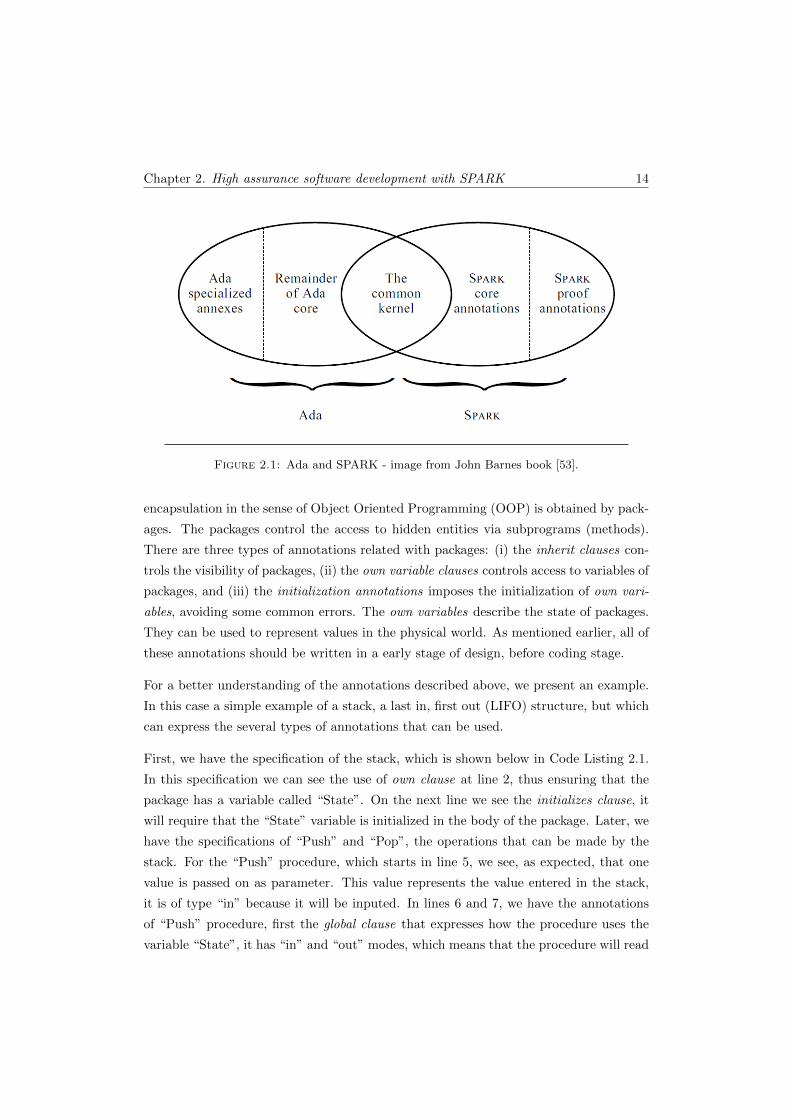
The relationship between Ada and SPARK can be seen in Figure 2.1; the overlap between
them refers to the kernel. The kernel does not contemplate the exceptions, generics
(templates), access (pointers) types, or goto statements, because they create difficulties
in proving that a program is correct.
The SPARK core annotations (flow analysis and visibility control) are divided into sev-
eral types. There exist two important annotations used to increment information given
by the normal Ada specification: (i) the global definitions, declare the use of global vari-
ables by subprograms - is called data flow analysis and only comprise the direction of
data flow (only use the global annotation); and (ii) dependency relations of procedures,
specify the information flow between their imports and exports via both parameters and
global variables - is called information flow analysis and uses in addition the dependency
between variables (using the derives annotation). The annotations for access variables
in packages are also very important. They allow modularity between components. The
Chapter 2. High assurance software development with SPARK 14
Figure 2.1: Ada and SPARK - image from John Barnes book [53].
encapsulation in the sense of Object Oriented Programming (OOP) is obtained by pack-
ages. The packages control the access to hidden entities via subprograms (methods).
There are three types of annotations related with packages: (i) the inherit clauses con-
trols the visibility of packages, (ii) the own variable clauses controls access to variables of
packages, and (iii) the initialization annotations imposes the initialization of own vari-
ables, avoiding some common errors. The own variables describe the state of packages.
They can be used to represent values in the physical world. As mentioned earlier, all of
these annotations should be written in a early stage of design, before coding stage.
For a better understanding of the annotations described above, we present an example.
In this case a simple example of a stack, a last in, first out (LIFO) structure, but which
can express the several types of annotations that can be used.
First, we have the specification of the stack, which is shown below in Code Listing 2.1.
In this specification we can see the use of own clause at line 2, thus ensuring that the
package has a variable called “State”. On the next line we see the initializes clause, it
will require that the “State” variable is initialized in the body of the package. Later, we
have the specifications of “Push” and “Pop”, the operations that can be made by the
stack. For the “Push” procedure, which starts in line 5, we see, as expected, that one
value is passed on as parameter. This value represents the value entered in the stack,
it is of type “in” because it will be inputed. In lines 6 and 7, we have the annotations
of “Push” procedure, first the global clause that expresses how the procedure uses the
variable “State”, it has “in” and “out” modes, which means that the procedure will read
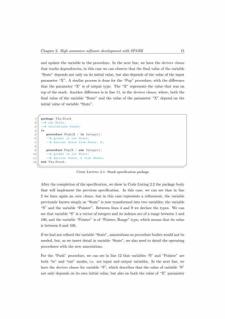
Chapter 2. High assurance software development with SPARK 15
and update the variable in the procedure. In the next line, we have the derives clause
that tracks dependencies, in this case we can observe that the final value of the variable
“State” depends not only on its initial value, but also depends of the value of the input
parameter “X”. A similar process is done for the “Pop” procedure, with the difference
that the parameter “X” is of output type. The “X” represents the value that was on
top of the stack. Another difference is in line 11, in the derives clause, where, both the
final value of the variable “State” and the value of the parameter “X” depend on the
initial value of variable “State”.
�1 package The Stack
2 --# own State ;
3 --# initializes State ;
4 i s
5 procedure Push (X : in I n t eg e r ) ;
6 --# global in out State ;
7 --# derives State from State , X;
8
9 procedure Pop(X : out I n t eg e r ) ;
10 --# global in out State ;
11 --# derives State , X from State ;
12 end The Stack ;� Code Listing 2.1: Stack specification package
After the completion of the specification, we show in Code Listing 2.2 the package body
that will implement the previous specification. In this case, we can see that in line
2 we have again an own clause, but in this case represents a refinement, the variable
previously known simply as “State” is now transformed into two variables, the variable
“S” and the variable “Pointer”. Between lines 4 and 9 we declare the types. We can
see that variable “S” is a vector of integers and its indexes are of a range between 1 and
100, and the variable “Pointer” is of “Pointer Range” type, which means that its value
is between 0 and 100.
If we had not refined the variable “State”, annotations on procedure bodies would not be
needed, but, as we insert detail in variable “State”, we also need to detail the operating
procedures with the new annotations.
For the “Push” procedure, we can see in line 12 that variables “S” and “Pointer” are
both “in” and “out” modes, i.e. are input and output variables. In the next line, we
have the derives clause for variable “S”, which describes that the value of variable “S”
not only depends on its own initial value, but also on both the value of “X” parameter
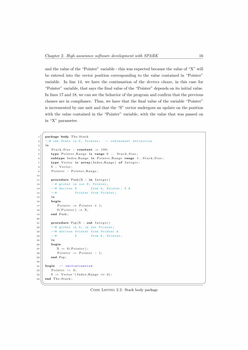
Chapter 2. High assurance software development with SPARK 16
and the value of the “Pointer” variable - this was expected because the value of “X” will
be entered into the vector position corresponding to the value contained in “Pointer”
variable. In line 14, we have the continuation of the derives clause, in this case for
“Pointer” variable, that says the final value of the “Pointer” depends on its initial value.
In lines 17 and 18, we can see the behavior of the program and confirm that the previous
clauses are in compliance. Thus, we have that the final value of the variable “Pointer”
is incremented by one unit and that the “S” vector undergoes an update on the position
with the value contained in the “Pointer” variable, with the value that was passed on
in “X” parameter.
�1 package body The Stack
2 --# own State is S , Pointer ; -- refinement definition
3 i s
4 Stack S i z e : constant := 100 ;
5 type Pointer Range i s range 0 . . S tack S i z e ;
6 subtype Index Range i s Pointer Range range 1 . . S ta ck S i z e ;
7 type Vector i s array ( Index Range ) of I n t eg e r ;
8 S : Vector ;
9 Pointer : Pointer Range ;
10
11 procedure Push (X : in I n t eg e r )
12 --# global in out S , Pointer ;
13 --# derives S from S , Pointer , X &
14 --# Pointer from Pointer ;
15 i s
16 begin
17 Pointer := Pointer + 1 ;
18 S( Pointer ) := X;
19 end Push ;
20
21 procedure Pop(X : out I n t eg e r )
22 --# global in S; in out Pointer ;
23 --# derives Pointer from Pointer &
24 --# X from S , Pointer ;
25 i s
26 begin
27 X := S( Pointer ) ;
28 Pointer := Pointer − 1 ;
29 end Pop ;
30
31 begin -- initialization
32 Pointer := 0 ;
33 S := Vector ’ ( Index Range => 0) ;
34 end The Stack ;� Code Listing 2.2: Stack body package
Chapter 2. High assurance software development with SPARK 17
Starting at line 21, we have the body of “Pop” procedure. In this case, we see that
“Pointer” variable continues to be of “in” and “out” modes, input and output respec-
tively - as happened in the specification of “State” variable - but “S” variable is only
of “in” mode, or just input - this is due to the fact that “S” is not updated in this
procedure. In line 23, begins the derives clause and we observe that the final value of
the “Pointer” variable depends only on its initial value. In the next line, we see that the
value of the parameter “X” depends on the values of “S” and “Pointer” variables, this
its because “X” will take the value contained in the vector “S” at the position equals
to the value contained in “Pointer” variable. In lines 27 and 28, we can confirm that
the operation does what expected, i.e. the “X” takes the value of the vector “S” in the
position of the value contained in “Pointer” and the “Pointer” is decremented by one
unit, depending its final value only on its initial value, without depending on any other
variable.
Last but not least, we have the initialization of “Pointer” and “S” variables, thereby
complying with initializes clause it was put in the specification of the package.
To ensure that a program cannot have certain errors related to the flow of information
(such as, the use of uninitialized variables and the overwriting of values before they are
used), the Examiner needs the SPARK language with its core annotations. However,
this kind of annotations does not address effectively the issue of dynamic behavior. To
deal with this, some proof annotations are added to allow analysis of dynamic behavior
prior to execution. The proof annotations can be as follows:
• Pre- and post-conditions of subprograms;
• Assertions, such as loop invariants and type assertions;
• Declarations of proof functions and proof types.
Continuing with the previous example of the stack, we show in Code Listing 2.3, how
proof annotations on “Push” and “Pop” procedures can be added. These annotations
should have been written before the code by another person other than the one who
wrote the code. For the “Push” procedure, a pre-condition annotation that checks
whether the value of “Pointer” is less than the value of “Stack Size” is in line 39 - this
is to prevent to access a position outside the bounds of the array. In the following two
lines the post-condition annotation was included - that shows us which values of “S” and
“Pointer” variables are obtained after the execution of the procedure. The final value of
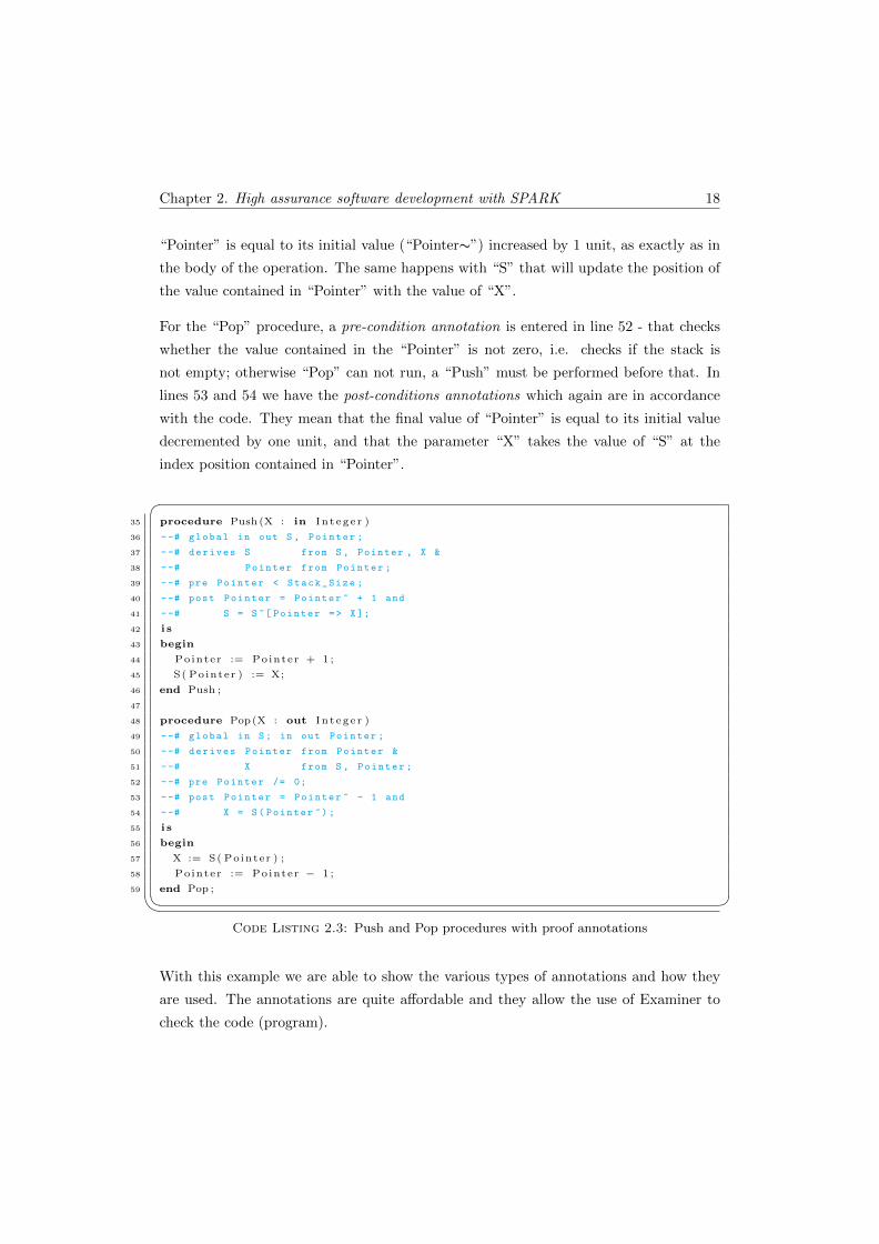
Chapter 2. High assurance software development with SPARK 18
“Pointer” is equal to its initial value (“Pointer∼”) increased by 1 unit, as exactly as in
the body of the operation. The same happens with “S” that will update the position of
the value contained in “Pointer” with the value of “X”.
For the “Pop” procedure, a pre-condition annotation is entered in line 52 - that checks
whether the value contained in the “Pointer” is not zero, i.e. checks if the stack is
not empty; otherwise “Pop” can not run, a “Push” must be performed before that. In
lines 53 and 54 we have the post-conditions annotations which again are in accordance
with the code. They mean that the final value of “Pointer” is equal to its initial value
decremented by one unit, and that the parameter “X” takes the value of “S” at the
index position contained in “Pointer”.
�35 procedure Push (X : in I n t eg e r )
36 --# global in out S , Pointer ;
37 --# derives S from S , Pointer , X &
38 --# Pointer from Pointer ;
39 --# pre Pointer < Stack_Size ;
40 --# post Pointer = Pointer ~ + 1 and
41 --# S = S ~[ Pointer => X ];
42 i s
43 begin
44 Pointer := Pointer + 1 ;
45 S( Pointer ) := X;
46 end Push ;
47
48 procedure Pop(X : out I n t eg e r )
49 --# global in S; in out Pointer ;
50 --# derives Pointer from Pointer &
51 --# X from S , Pointer ;
52 --# pre Pointer /= 0;
53 --# post Pointer = Pointer ~ - 1 and
54 --# X = S( Pointer ~) ;
55 i s
56 begin
57 X := S( Pointer ) ;
58 Pointer := Pointer − 1 ;
59 end Pop ;� Code Listing 2.3: Push and Pop procedures with proof annotations
With this example we are able to show the various types of annotations and how they
are used. The annotations are quite affordable and they allow the use of Examiner to
check the code (program).
Chapter 2. High assurance software development with SPARK 19
Technically, the SPARK was born through the work of Bob Phillips in 1970 at the Royal
Signals and Radar Establishment. The study consisted of understanding and analyzing
the behavior of existing programs and developed tools to perform such analysis. The
idea gained notoriety with the importance of the correction of software for applications
with critical security. In 1994 there appears the first version of SPARK (based on Ada
83) produced at the University of Southampton (with the support of the Ministry of
Defense of the United Kingdom) by Bernard Carre and Trevor Jennings.
Later, the language was gradually augmented and refined, first by Program Validation
Limited and later by Praxis Critical Systems Limited. In 1995 the Ada language was
revised, which resulted in the Ada 95, and in 2002 SPARK was adjusted so the language
corresponded to the version of Ada 95. In 2004, Praxis Critical Systems Limited changed
its name to Praxis High Integrity Systems Limited and in 2007 appears a new version
of the standard, called Ada 2005 to be distinguished from the previous version. More
recently, in 2009, a partnership with AdaCore resulted in the release of “SPARK Pro”
under the terms of GPL. In the middle of 2009, the SPARK GPL 2010 Edition emerged
with an initial set of new features for SPARK 2005. In 2010 the company merged with
SC2 to form Altran Praxis, which is now the company responsible for maintaining and
developing SPARK. More details on the history of SPARK can be found at [3, 53].
Although SPARK has emerged from a study where the initial objective was to verify
existing programs, the primary objective now is to write programs correctly.
2.3 Development methodology
In all engineering disciplines it is widely accepted that it is better to avoid the intro-
duction of errors beforehand rather than having to correct them at a later stage. For
example, as far as a manufactured physical component is concerned, realizing at a late
state that an entire batch of such a component was made out of the specifications, has
huge costs. This may also happen in software development. Generally, the later the er-
rors are found, the more expensive is to eliminate them. Those corrections may represent
a very large percentage of the development costs when we talk about critical systems
with high standards. The only way of obtaining the high levels of integrity required for
critical software at an acceptable cost, is by pursuing development methods that make
it hard to introduce errors and which facilitates their early detection. This is achieved
by an approach sometimes termed as Correctness by Construction [4].
Chapter 2. High assurance software development with SPARK 20
2.3.1 Correctness by construction
This process has been successfully used by Praxis in many projects. The proposed
process by Altran Praxis consists overall of the following five steps:
1. Requirements analysis;
2. Formal specification (using the formal language Z);
3. Design (INFORMED process);
4. Implementation in SPARK;
5. Verification (using the SPARK Examiner toolset).
As expected, requirements analysis is essential in any software project, so we need to
make explicit, first, what the software is supposed to do, and secondly, what their
features and peculiarities are. However, the passage of the requirements in text form to
implementation in code is not always easy to do, mostly because they have not specified
in an unambiguous way how to be implemented. To circumvent this problem, it is
recommended the modeling of requirements in order to eliminate possible ambiguities
in the requirements and for better understanding of the problem. One of the modeling
languages mostly used for this purpose is the Unified Modeling Language (UML), which
allows (depending on the type of the UML models) a more visual perspective of the
requirements and the software functionalities. There is an extensive list of UML model
types, and its creation does not always follow the same pattern, making it unclear and
informal, allowing more than one interpretation with the same model or introduces
difficulties to disambiguate certain requirements. On the other hand, using a formal
modeling language, it is possible to express the requirements in an unambiguous way,
so that there is only one interpretation of the problem.
The SPARK language and its support tool, the Examiner, are designed expressly to
support the CbyC paradigm, allowing an early stage detection of errors. This avoids the
normal validation by testing at the end of a project, with all the costs associated. A key
ingredient of the CbyC approach is an effective design method known by INFORMED.
This method is well defined by Praxis. Bellow we present its major aspects. This method
builds on the minimization of the flow of information between subsystems. INFORMED
is an INformation Flow ORiented MEthod of (object) Design. Unnecessary flow of
information between different parts of the system increases considerably the complexity

Chapter 2. High assurance software development with SPARK 21
of the SPARK annotations and consequently the difficulty of proofs. This can be done
by minimizing propagation of unnecessary detail with: a) a correct localization and
encapsulation of state; and b) avoiding making copies of data with an appropriate use
of hierarchy. Another principle is a clear separation of the essential from the inessential.
This gives priority to the core functionality of the system.
In the next two sections, we present steps 2 and 3 of the development process, the Formal
specification step (which in this case is made with the formal language Z) and the Design
step (that consists in the use of INFORMED process) respectively.
2.3.1.1 Formal specification
As mentioned earlier, it is extremely important to create a formal model of the problem.
This methodology uses the Z notation to achieve this.
Hereby we introduce the basics of Z notation, with its types and schemas.
The main building block in Z is a schema. A Z schema takes the form of a number of
state components and, optionally, constraints on the state.
SchemaName
declarations
constraints
The next schema represents a clock with hours and minutes. The obvious two constraints
are introduced: a) the value of the hours (h) must be between 0 and 23; and b) the value
of the minutes (m) must be between 0 and 59.
Clock
h :
m :
h < 24 ∧ m < 60
Schemas are used to describe behavior under change. To represent the new values of the
state, the “ ′ ” single quote is used.
Chapter 2. High assurance software development with SPARK 22
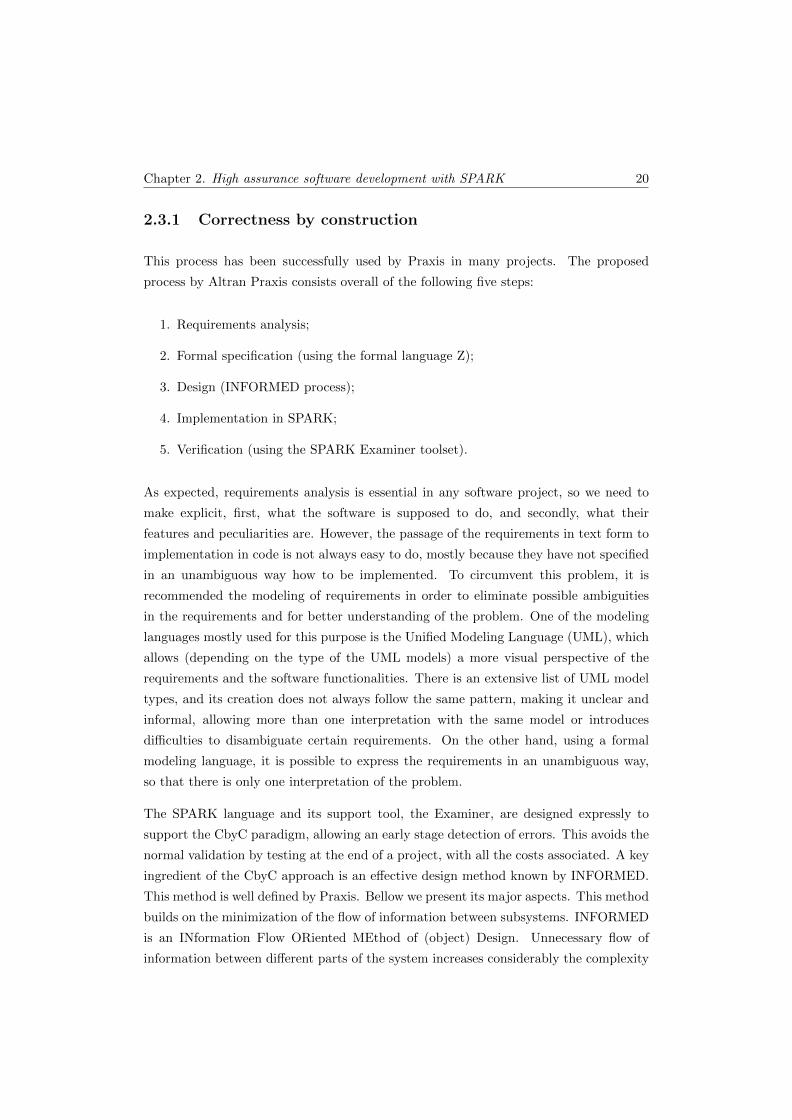
We can describe a simple increment in a minute of our clock. Note that the constraints
introduced in the above schema are still valid.
IncrementMinute
∆Clock
h ′ = h
m ′ = m + 1
The ∆Clock means that a change occurs on the state. Another useful definition is ΞClock
which describes the case where the state of the schema is unchanged. For example, for
operations that only have “read” permission.
In addition to schemas, Z allows us to define basic types which will be used thereafter
in the components of our schemas. Next, we introduce the concept of “alarm”, that can
be used to extend a simple clock to an alarm clock.
[ALARM ]
We can introduce axiomatic descriptions like:
seconds :
seconds ≤ 59
We introduce the seconds with an obvious constraint, that they must be contained
between 0 and 59, and then let us introduce the alarm clock, with hours and minutes of
the previous Clock plus seconds and a buzz.
AlarmClock
Clock
s : seconds
buzz : ALARM
Only the basic notions of language were presented, with its basic elements. For a more
complete description of the language please read [54].

Chapter 2. High assurance software development with SPARK 23
2.3.1.2 INFORMED
The INFORMED design approach is a very important step because describes how
SPARK deals with properties of good software design, such as:
• Abstraction: this enables us to ignore certain levels of detail. Hiding unnecessary
detail allows us to focus on the essential properties of an object;
• Encapsulation: it is a separation of specification from implementation. The users
of an object should not be concerned with its internal behavior;
• Loose coupling: coupling is a measure of the strength of connections between
objects. High levels of coupling make modifications difficult to be performed as
changes occur in more than one place. On contrary, loose coupling makes modifi-
cations easy to occur;
• Low Cohesion: cohesion is a measure of the strength of connections between an
object attributes. A low degree of separation of attributes (low cohesion) allows
us to perform changes in a single attribute leaving the remaining unchanged. For
example, a car has an engine and doors, which represent two distinct attributes of
the car object; any change in the driver’s door does not affect at all the engine of
the car.
• Hierarchy: certain objects are contained inside others and cannot be reached
directly. For example, when we see a car we see immediately the doors too, but
to see the engine is necessary to access the car and open the hood.
The INFORMED is composed by five blocks, that form the basic design elements:
• Main program: this control the behavior of the entire system. It requires the
SPARK annotation main program;
• Variable package: this is the same as usually known as abstract state machine
or an object for example in Java. It is a SPARK package that contains static data
or “state”. It is annotated by an own variable annotation;
• Type package: known as abstract data type or a more vulgar class. It is also a
SPARK package although in this case does not have state;
• Utility Layer: introduces operations to the system but does not introduce state
or types;
Chapter 2. High assurance software development with SPARK 24
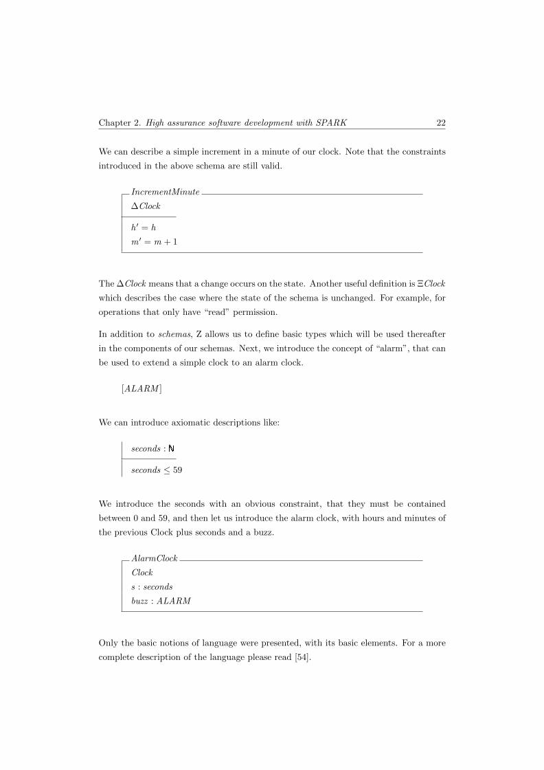
• Boundary Variable: these variables are used to represent real world entities.
The following notation, shown in Figure 2.2, is used to express the diagrams of the
system structure:
Figure 2.2: The INFORMED notation - image adapted from [55].
The arrows represent the dependence between elements (the element at the arrow head
is used (inherited) by the element at the arrow’s tail) and can be separated into:
• Strong coupling: represents use, either directly or indirectly of the global vari-
ables of a package;
• Weak coupling: represents use of types and utilities provided by a package
without using or affecting the state of the package.
The INFORMED design normally follows a few steps. The process consists of finding
a solution for each step and test them with the goal to move on to the next step. If
one step is becoming too complicated, possibly a wrong choice has been made in the
previous step. The steps are:
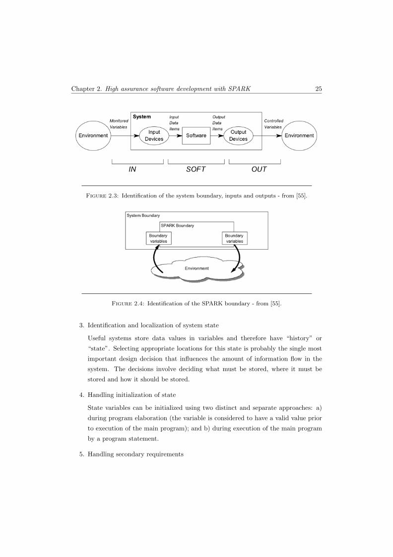
1. Identification of the system boundary, inputs and outputs
First, choosing and delineating the boundary system. Also identification and se-
lection of the physical inputs and outputs, as described in Figure 2.3.
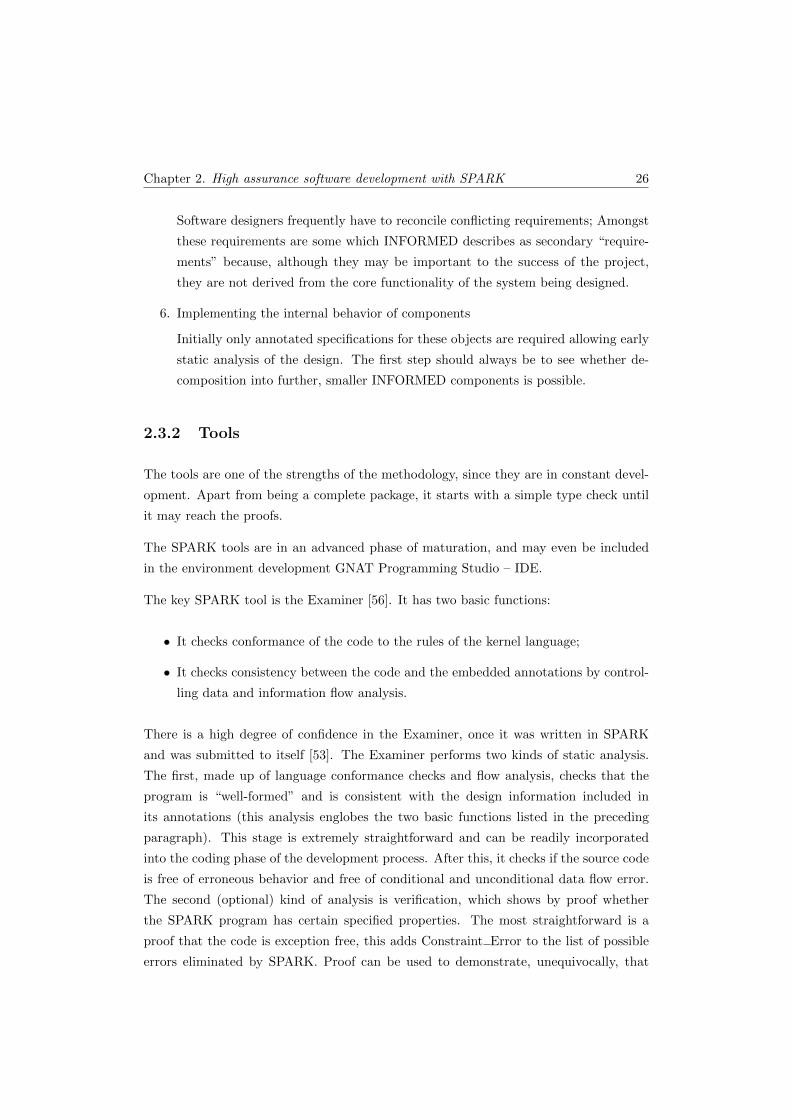
2. Identification of the SPARK boundary
The selection of the boundary variables defines the SPARK system boundary, this
can be seen in Figure 2.4. The abstracted input/output values provided by the
boundary variables are the Input Data Items and Output Data Items from Figure
2.3.
Chapter 2. High assurance software development with SPARK 25
Figure 2.3: Identification of the system boundary, inputs and outputs - from [55].
Figure 2.4: Identification of the SPARK boundary - from [55].
3. Identification and localization of system state
Useful systems store data values in variables and therefore have “history” or
“state”. Selecting appropriate locations for this state is probably the single most
important design decision that influences the amount of information flow in the
system. The decisions involve deciding what must be stored, where it must be
stored and how it should be stored.
4. Handling initialization of state
State variables can be initialized using two distinct and separate approaches: a)
during program elaboration (the variable is considered to have a valid value prior
to execution of the main program); and b) during execution of the main program
by a program statement.
5. Handling secondary requirements
Chapter 2. High assurance software development with SPARK 26
Software designers frequently have to reconcile conflicting requirements; Amongst
these requirements are some which INFORMED describes as secondary “require-
ments” because, although they may be important to the success of the project,
they are not derived from the core functionality of the system being designed.
6. Implementing the internal behavior of components
Initially only annotated specifications for these objects are required allowing early
static analysis of the design. The first step should always be to see whether de-
composition into further, smaller INFORMED components is possible.
2.3.2 Tools
The tools are one of the strengths of the methodology, since they are in constant devel-
opment. Apart from being a complete package, it starts with a simple type check until
it may reach the proofs.
The SPARK tools are in an advanced phase of maturation, and may even be included
in the environment development GNAT Programming Studio – IDE.
The key SPARK tool is the Examiner [56]. It has two basic functions:
• It checks conformance of the code to the rules of the kernel language;
• It checks consistency between the code and the embedded annotations by control-
ling data and information flow analysis.
There is a high degree of confidence in the Examiner, once it was written in SPARK
and was submitted to itself [53]. The Examiner performs two kinds of static analysis.
The first, made up of language conformance checks and flow analysis, checks that the
program is “well-formed” and is consistent with the design information included in
its annotations (this analysis englobes the two basic functions listed in the preceding
paragraph). This stage is extremely straightforward and can be readily incorporated
into the coding phase of the development process. After this, it checks if the source code
is free of erroneous behavior and free of conditional and unconditional data flow error.
The second (optional) kind of analysis is verification, which shows by proof whether
the SPARK program has certain specified properties. The most straightforward is a
proof that the code is exception free, this adds Constraint Error to the list of possible
errors eliminated by SPARK. Proof can be used to demonstrate, unequivocally, that
Chapter 2. High assurance software development with SPARK 27
the code maintains important safety or security properties or even to show its complete
conformance with some suitable specification.
Based on proof annotations, the Examiner generate verification conditions (potential
theorems) which then have to be proved in order to verify whether the program is correct
with respect to the annotations. The verification conditions can be proved manually in
a process usually tedious and unreliable, or by using other tools such as the Simplifier
[57] and the Proof Checker [58].
The Simplifier is an automated theorem prover that processes the verification conditions
(VCs) produced by the Examiner. The proof of these VCs confirms critical program
properties, such as the freedom from run-time errors and exceptions, or specific safety
and security properties. The Simplifier main purpose is to simplify verification conditions
prior to developing a proof, but in many cases is able to reduce all the conclusions to
True. Any remaining undischarged conditions may be proved with the assistance of the
Proof Checker. This is an interactive proof tool that uses the same logic and inference
engine as the Simplifier. For a more readable visualization of results POGS (Proof
Obligation Summary Tool) [59] summarizes the semantic output files produced by the
Examiner, the Simplifier and the Proof Checker.
The use of tools like Examiner encourages the early use of a V&V (Verification and
Validation) approach. This is made possible with code written in SPARK with appro-
priate annotations and that are now able to be processed by Examiner, even if it still
can not be compiled. This is clearly the recommended approach, strongly discouraging
the consideration of an existing piece of Ada code and then add to it the annotations
(known as “Sparking Ada”). This is because it typically leads to extensive annotations
indicative of an unnecessarily complex structure. To avoid this, the annotations should
be seen as part of the design process.
2.4 Summary
The use of formal methods is important and even necessary for certain types of software.
Its use leads to more robust and more reliable software. There are various types of FM
that can and should be used for distinct purposes. As suggested by the development
method CbyC, SPARK needs to be introduced in the beginning of the software devel-
opment, not only in the common validation and verification stage, thus including also
this phase of the process from the very beginning. The INFORMED approach capture

Chapter 2. High assurance software development with SPARK 28
system design information in annotations and use it to influence the shape and char-
acteristics of the software implementing that system. The use of SPARK at the design
stage of the life cycle facilitates a cost-efficient CbyC development method.
Chapter 3
Case study: a secure
partitioning microkernel
The use of embedded devices has significantly grown in the last years. We have this type
of devices in any place around us. In cars, in mobiles, in houses and much more. This
type of devices is increasingly connected to the Internet. This can be a big vulnerability
because it creates opportunities for malicious users to exploit security weaknesses and
take control of these systems. These malicious people can access confidential informa-
tion, disable a critical system, or modify its default behavior. It is therefore necessary
to develop highly secure embedded systems to ensure our safety. Besides those already
mentioned, these embedded devices are also located in critical areas for homeland secu-
rity, such as Internet service providers, financial institutions or power companies. For
this, it is urgent to ensure the software of these devices is highly secure. In particular,
it is necessary that the embedded operating system is secure or “bullet proof”. The OS
is vital, because any application or security mechanism implemented could be bypassed,
if the OS is not safe in the first place.
The development of a commercial operating system usually follows the “Penetrate and
Patch” approach [60]. OS are attacked by viruses, worms and trojan horses, highlighting
their vulnerabilities. Thus vendors developed and released patches to fix the vulnerabil-
ities, almost by a trial and error method. Clearly this kind of approach is ineffective for
the systems we are talking about. The right solution is to provide an approach where
systems are designed to be safe and secure from the very beginning. To meet this need,
29
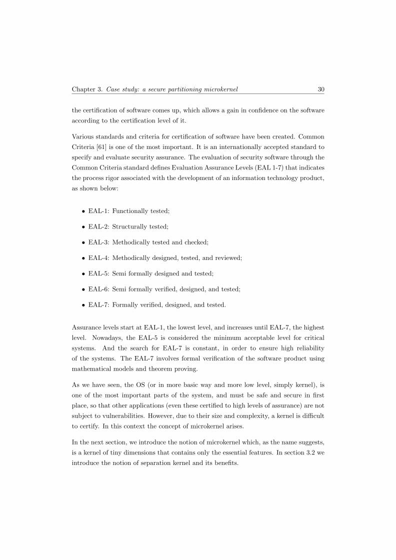
Chapter 3. Case study: a secure partitioning microkernel 30
the certification of software comes up, which allows a gain in confidence on the software
according to the certification level of it.
Various standards and criteria for certification of software have been created. Common
Criteria [61] is one of the most important. It is an internationally accepted standard to
specify and evaluate security assurance. The evaluation of security software through the
Common Criteria standard defines Evaluation Assurance Levels (EAL 1-7) that indicates
the process rigor associated with the development of an information technology product,
as shown below:
• EAL-1: Functionally tested;
• EAL-2: Structurally tested;
• EAL-3: Methodically tested and checked;
• EAL-4: Methodically designed, tested, and reviewed;
• EAL-5: Semi formally designed and tested;
• EAL-6: Semi formally verified, designed, and tested;
• EAL-7: Formally verified, designed, and tested.
Assurance levels start at EAL-1, the lowest level, and increases until EAL-7, the highest
level. Nowadays, the EAL-5 is considered the minimum acceptable level for critical
systems. And the search for EAL-7 is constant, in order to ensure high reliability
of the systems. The EAL-7 involves formal verification of the software product using
mathematical models and theorem proving.
As we have seen, the OS (or in more basic way and more low level, simply kernel), is
one of the most important parts of the system, and must be safe and secure in first
place, so that other applications (even these certified to high levels of assurance) are not
subject to vulnerabilities. However, due to their size and complexity, a kernel is difficult
to certify. In this context the concept of microkernel arises.
In the next section, we introduce the notion of microkernel which, as the name suggests,
is a kernel of tiny dimensions that contains only the essential features. In section 3.2 we
introduce the notion of separation kernel and its benefits.
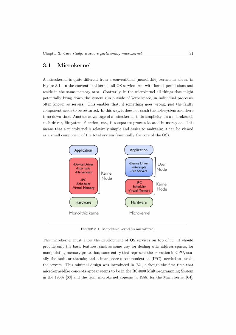
Chapter 3. Case study: a secure partitioning microkernel 31
3.1 Microkernel
A microkernel is quite different from a conventional (monolithic) kernel, as shown in
Figure 3.1. In the conventional kernel, all OS services run with kernel permissions and
reside in the same memory area. Contrarily, in the microkernel all things that might
potentially bring down the system run outside of kernelspace, in individual processes
often known as servers. This enables that, if something goes wrong, just the faulty
component needs to be restarted. In this way, it does not crash the hole system and there
is no down time. Another advantage of a microkernel is its simplicity. In a microkernel,
each driver, filesystem, function, etc., is a separate process located in userspace. This
means that a microkernel is relatively simple and easier to maintain; it can be viewed
as a small component of the total system (essentially the core of the OS).
Figure 3.1: Monolithic kernel vs microkernel.
The microkernel must allow the development of OS services on top of it. It should
provide only the basic features, such as some way for dealing with address spaces, for
manipulating memory protection; some entity that represent the execution in CPU, usu-
ally the tasks or threads; and a inter-process communication (IPC), needed to invoke
the servers. This minimal design was introduced in [62], although the first time that
microkernel-like concepts appear seems to be in the RC4000 Multiprogramming System
in the 1960s [63] and the term microkernel appears in 1988, for the Mach kernel [64].

Chapter 3. Case study: a secure partitioning microkernel 32
Nevertheless, for efficiency purposes, some microkernels include the scheduler in ker-
nelspace. Many projects have attempted the kernel formalization, having in mind the
certification. This degree of assurance goes in the path of EAL-7. With this kind of
practices, the microkernel designs have also been used in systems made for high-security
applications, like military systems.
However, these types of systems have various types of applications, some more important
than others. For example, in a plane it is not hard to imagine that the application which
controls the temperature is slightly less important than the applications that controls
the engines. The solution was to have several computers, each of which controlling only
a single application. In this way, if any of them fails or has unexpected behavior, there
is not harm or change in the functioning of any other. However, if for each function we
have different hardware, it can easily be seen that for certain systems this solution is
inadequate.
Thus, the need for new solutions arises. This case is essentially a rediscover of the
concept of separation kernel. At the time it was introduced [65] it was not given a great
importance, because at the time there was no need for such architecture. However, times
changed and the concept was reviewed.
3.2 Separation kernel
The need to run separate applications on the same hardware has increased the relevance
of the concept of separation kernel. It is preferable to run several applications on the
same hardware than having several hardwares, one for each application. There are
great advantages in this approach. In some systems it is even impossible due to lack of
physical space (for example in robots of exploration). The major disadvantage of having
each application in a independent machine is the redundancy of resources. This leads
to disadvantages such as higher costs, more space occupied and power consumed. An
increasing of cooling, weight and more difficult installation and maintenance.
The concept of separation kernel was introduced by John Rushby in 1981 at the ACM
Symposium on Operating System Principles [65]. He introduced a new paradigm for
secure computing by redefining the mission of the OS security kernel in same way as a
distributed system. The new kernel simulates a distributed environment with only one
processor and ensures that there is no interaction between the properties of the kernel
Chapter 3. Case study: a secure partitioning microkernel 33
and the properties of the components that form such system. The separation between
components enables independent verification of the kernel and its components.
The use of this type of kernel is based on the concept of separation or partition. The main
purpose is to isolate faults of one component from the others. A failure or unexpected
behavior in one partition (component) must not cause failure or unexpected behavior in
another partitions.
The partitioning is divided in spatial partitioning and temporal partitioning. The spatial
partitioning must ensure that software in one partition cannot modify the software of
another partition. The address space of each partition is therefore isolated. Temporal
partitioning must ensure that for all the partitions - one at a time - a time slot is given
for shared resources, such as the CPU.
Until this point we used the term application to describe the computational entity within
a partition. This term depends on the implementation. An application could correspond
to the OS notions of process, or virtual machine, or other different notions. Generally,
an application is composed by smaller units of computation that are called or scheduled
separately. Again, this depends on the implementation, but generally these units are
tasks or threads. Partitioning must prevent applications to interfere with each other,
but the tasks within a single application are not protected from one another.
3.2.1 Spatial partitioning
The goal of spatial partitioning is to provide a mechanism to divide the memory, both
physical and virtual. This enables assigning a block of memory to each partition. The
addresses in this block are visible only for the partition owner of the block; all the other
partitions cannot access this piece of memory. This ensures that the other partitions do
not interfere in this memory space.
The most common mechanism used to guaranty that there are no violations of spatial
partitioning is provided by the hardware, either by the processor running mode, the
memory management unit (MMU), or a combination of both. The basic idea is that
the processor has two modes of operation (it can possibly have more): when in user
mode - the lowest privileged - the access to memory addresses are either checked or
translated using tables in the MMU. These tables can not be modified. Only the kernel
running in privilege mode can do it. The locations of blocks of memory in each partition
Chapter 3. Case study: a secure partitioning microkernel 34
are disjoint as expected. The only exception are the locations used for inter-partition
communications. The communications are discussed below.
The tasks executed in a partition access both the processor registers and the memory.
This information is called the context of a partition. When one partition is suspended
and another one starts, the kernel saves firstly the context of the partition being sus-
pended and secondly reloads the context saved for the partition that is meant to be
executed next.
3.2.2 Temporal partitioning
The temporal partitioning must guarantee that the execution of one partition does not
disturb the timing of events in other partitions. A mechanism is necessary to ensure
that a partition is executed in a dedicated time slot and that this slot of time will always
be available for this partition, unaffected by the execution of the remaining partitions.
In our microkernel, the sequence of execution time given to each partition is statically
scheduled to ensure determinism and simplification of the model.
The main problem to be solved is that one partition may get or keep exclusively posses-
sion of the CPU for itself. This can occur by bad intentions or simply by an error where
an application is retained in a infinite loop.
The most straightforward manner to overcome this problem is by scheduling at two levels,
as we can seen in Figure 3.2: first, the kernel schedules the partitions; then, the partition
schedules locally its own tasks. Usually, static scheduling is used at partition level. The
kernel ensures that the partition runs for a determined time at a specific frequency (for
example runs 10 ms, every 100 ms). Then, the scheduling inside a partition is dynamic -
based on common priorities of tasks. This gives the partition that is running the illusion
of exclusive access to computing resources. The concept of paravirtualization has the
same principles, where each partition is a virtualized OS, such as Linux or Windows.
3.3 Security partitioning and MILS
Besides space and time partitioning, and due to the need of information exchange be-
tween partitions, the necessity of information flow control emerges.
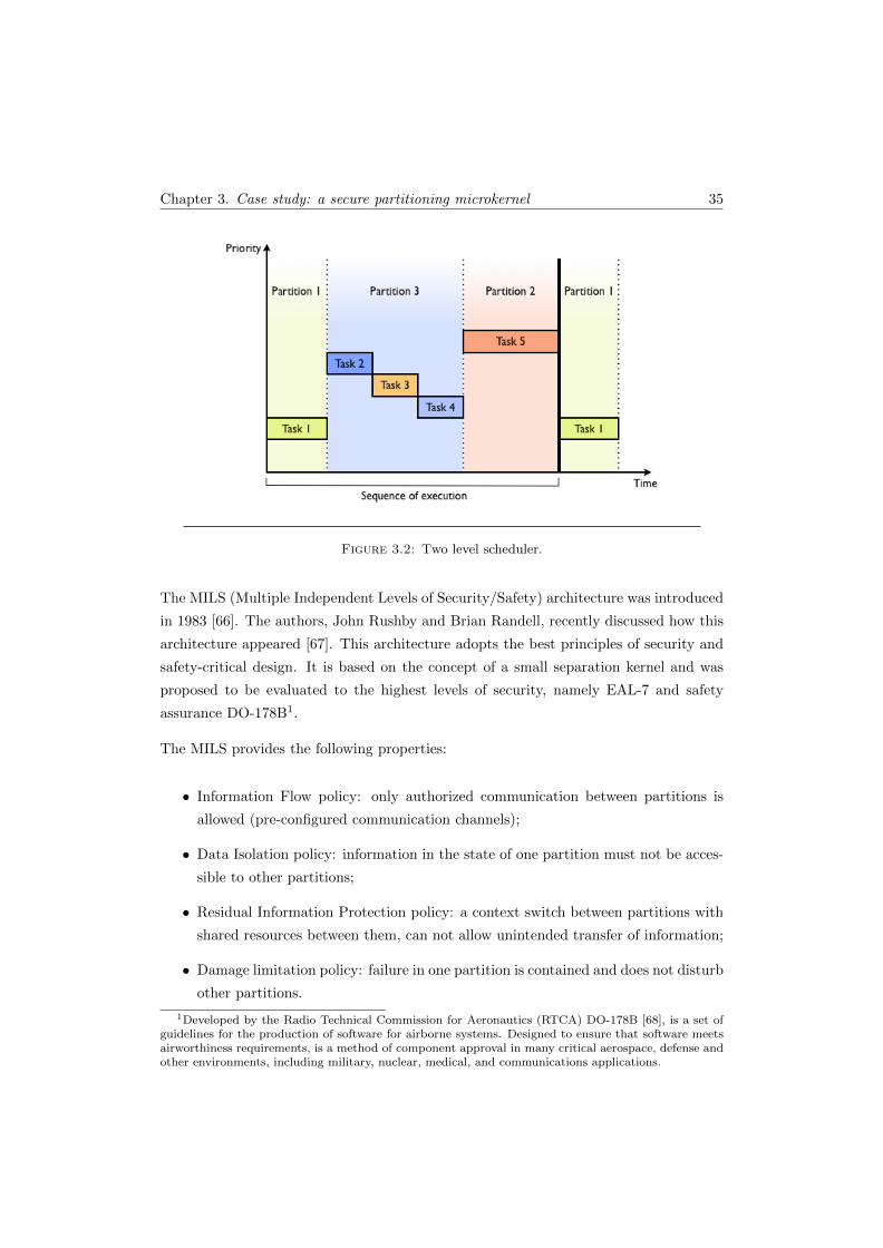
Chapter 3. Case study: a secure partitioning microkernel 35
Figure 3.2: Two level scheduler.
The MILS (Multiple Independent Levels of Security/Safety) architecture was introduced
in 1983 [66]. The authors, John Rushby and Brian Randell, recently discussed how this
architecture appeared [67]. This architecture adopts the best principles of security and
safety-critical design. It is based on the concept of a small separation kernel and was
proposed to be evaluated to the highest levels of security, namely EAL-7 and safety
assurance DO-178B1.
The MILS provides the following properties:
• Information Flow policy: only authorized communication between partitions is
allowed (pre-configured communication channels);
• Data Isolation policy: information in the state of one partition must not be acces-
sible to other partitions;
• Residual Information Protection policy: a context switch between partitions with
shared resources between them, can not allow unintended transfer of information;
• Damage limitation policy: failure in one partition is contained and does not disturb
other partitions.
1Developed by the Radio Technical Commission for Aeronautics (RTCA) DO-178B [68], is a set ofguidelines for the production of software for airborne systems. Designed to ensure that software meetsairworthiness requirements, is a method of component approval in many critical aerospace, defense andother environments, including military, nuclear, medical, and communications applications.
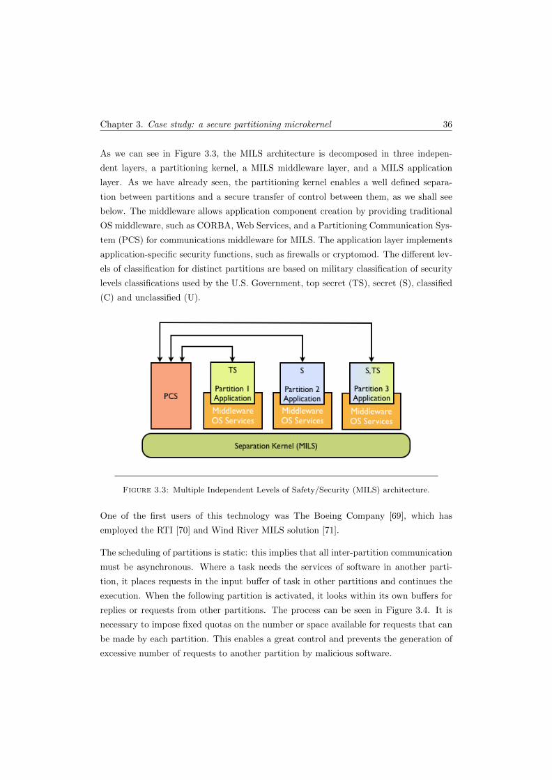
Chapter 3. Case study: a secure partitioning microkernel 36
As we can see in Figure 3.3, the MILS architecture is decomposed in three indepen-
dent layers, a partitioning kernel, a MILS middleware layer, and a MILS application
layer. As we have already seen, the partitioning kernel enables a well defined separa-
tion between partitions and a secure transfer of control between them, as we shall see
below. The middleware allows application component creation by providing traditional
OS middleware, such as CORBA, Web Services, and a Partitioning Communication Sys-
tem (PCS) for communications middleware for MILS. The application layer implements
application-specific security functions, such as firewalls or cryptomod. The different lev-
els of classification for distinct partitions are based on military classification of security
levels classifications used by the U.S. Government, top secret (TS), secret (S), classified
(C) and unclassified (U).
Figure 3.3: Multiple Independent Levels of Safety/Security (MILS) architecture.
One of the first users of this technology was The Boeing Company [69], which has
employed the RTI [70] and Wind River MILS solution [71].
The scheduling of partitions is static: this implies that all inter-partition communication
must be asynchronous. Where a task needs the services of software in another parti-
tion, it places requests in the input buffer of task in other partitions and continues the
execution. When the following partition is activated, it looks within its own buffers for
replies or requests from other partitions. The process can be seen in Figure 3.4. It is
necessary to impose fixed quotas on the number or space available for requests that can
be made by each partition. This enables a great control and prevents the generation of
excessive number of requests to another partition by malicious software.
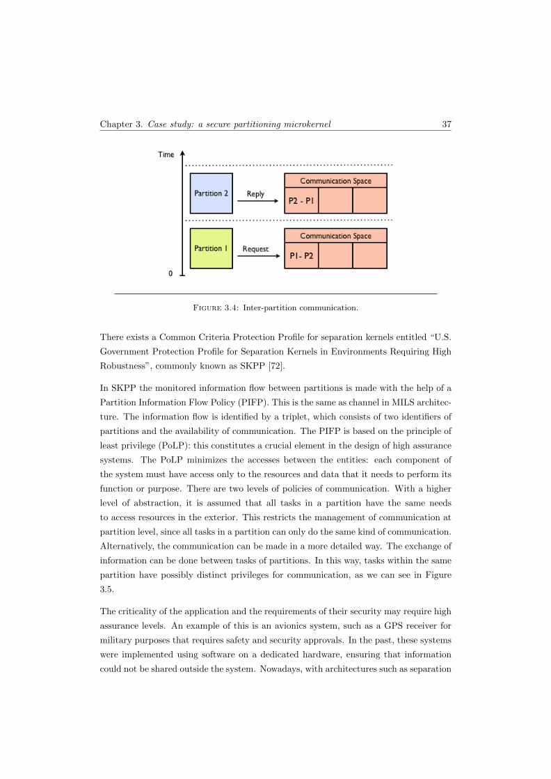
Chapter 3. Case study: a secure partitioning microkernel 37
Figure 3.4: Inter-partition communication.
There exists a Common Criteria Protection Profile for separation kernels entitled “U.S.
Government Protection Profile for Separation Kernels in Environments Requiring High
Robustness”, commonly known as SKPP [72].
In SKPP the monitored information flow between partitions is made with the help of a
Partition Information Flow Policy (PIFP). This is the same as channel in MILS architec-
ture. The information flow is identified by a triplet, which consists of two identifiers of
partitions and the availability of communication. The PIFP is based on the principle of
least privilege (PoLP): this constitutes a crucial element in the design of high assurance
systems. The PoLP minimizes the accesses between the entities: each component of
the system must have access only to the resources and data that it needs to perform its
function or purpose. There are two levels of policies of communication. With a higher
level of abstraction, it is assumed that all tasks in a partition have the same needs
to access resources in the exterior. This restricts the management of communication at
partition level, since all tasks in a partition can only do the same kind of communication.
Alternatively, the communication can be made in a more detailed way. The exchange of
information can be done between tasks of partitions. In this way, tasks within the same
partition have possibly distinct privileges for communication, as we can see in Figure
3.5.
The criticality of the application and the requirements of their security may require high
assurance levels. An example of this is an avionics system, such as a GPS receiver for
military purposes that requires safety and security approvals. In the past, these systems
were implemented using software on a dedicated hardware, ensuring that information
could not be shared outside the system. Nowadays, with architectures such as separation
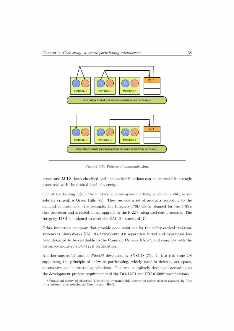
Chapter 3. Case study: a secure partitioning microkernel 38
Figure 3.5: Policies of communication.
kernel and MILS, both classified and unclassified functions can be executed in a single
processor, with the desired level of security.
One of the leading OS in the military and aerospace markets, where reliability is ab-
solutely critical, is Green Hills [73]. They provide a set of products according to the
demand of customers. For example, the Integrity-178B OS is planned for the F-35’s
core processor and is slated for an upgrade to the F-22’s integrated core processor. The
Integrity-178B is designed to meet the EAL-6+ standard [74].
Other important company that provide good solutions for the safety-critical real-time
systems is LinuxWorks [75]. Its LynxSecure 3.0 separation kernel and hypervisor has
been designed to be certifiable to the Common Criteria EAL-7, and complies with the
aerospace industry’s DO-178B certification.
Another successful case, is PikeOS developed by SYSGO [76]. It is a real time OS
supporting the principle of software partitioning, widely used in defense, aerospace,
automotive, and industrial applications. This was completely developed according to
the development process requirements of the DO-178B and IEC 615082 specifications.
2Functional safety of electrical/electronic/programmable electronic safety-related systems by TheInternational Electrotechnical Commission (IEC).
Chapter 3. Case study: a secure partitioning microkernel 39
3.4 Summary
As seen throughout this chapter, the main characteristic of a microkernel is to have
some OS services running in user mode. This makes the microkernel simpler, safer,
and smaller, when compared with the normal kernels (monolithics). The microkernel is
therefore the ideal candidate to serve as the basis for the separation kernel, which arises
from the need of a system having to execute - in the same hardware - different tasks
independently and securely. We also introduce the secure partitioning microkernel that,
apart from containing space partitioning and time partitioning - which are included in
most recent microkernels - also contains secure communications, thus making it different
from others.
As can be seen in this chapter, building a secure partitioning microkernel is not an easy
task. The solution proposed to build the system - as mentioned previously - is based on
the CbyC development method. The work consists of the following steps:
1. To survey the requirements for the analysis of the system - i.e. obtaining the
necessary information to move forward towards the system implementation goal;
2. To build a high-level specification in a formal language (Z notation) - this step is
important for a full understanding of the features and properties of the system;
3. To use the INFORMED process in order to obtain a cleaner and more consistent
programming, removing repeated code and unnecessary exchange of information;
4. To implement the system in SPARK;
5. To verify the system (using the SPARK Examiner toolset).
Before undertaking this, we will review in the following chapter similar applications
implementing formalization and verification of kernels that are available from the liter-
ature.
Chapter 4
Formal approaches to kernel
development
There are many works in the literature on the subject of formalizing Kernels. This
is understandable because the kernel is the central core of any computing system and
its proper functioning is essential. The use of FM is of utmost importance because
it allows us to have a formal specification of a kernel that represents an unambiguous
description of its features (requirements) for the developers. A formal specification of
a kernel also serves to provide the basis for the verification of an implementation of
the kernel. The most usual technique is to prove that a formal representation of the
implementation is equivalent to the top level specification. Normally, the use of simple
formal notations and various levels of refinements aim to facilitate either manual proof or
the use of an automatic theorem prover. On the other hand, there is also the possibility
to verify directly on the implementation level without a more abstract specification
of its behavior. The works in literature related to the verification of kernels present
various levels of abstraction and various levels of completion. More recent projects,
which achieved satisfactory results, have benefited of the constant evolution of tools.
For example, the automation achieved with current theorem provers is a fundamental
help in the verification process, avoiding (at least in part) a tedious and very specialized
job.
In this chapter, we present the related work to formalization of both traditional and
separation kernels. Besides this, a more interested reader may consult the article, which
40
Chapter 4. Formal approaches to kernel development 41
served as the main reference for this chapter, on past and present approaches to kernel
verification [77]. This chapter includes some works described in that article, though in
less detail; it also describes other works that seem relevant in the context of our work.
In the penultimate section we present the Tokeneer project that was of great relevance
in the choices made in our work.
4.1 Traditional kernels
Earlier work on OS kernel formalization and verification includes Provably Secure Op-
erating System (PSOS) [78] and UCLA Secure Unix [79]. The focus of these works
was on capability-based security kernels, allowing security policies such as multi-level
security to be enforced. These efforts were hampered by the lack of mechanization and
appropriate tools available at the time, and so, while the designs were formalized, the
full verification proofs were not practical. Later, with the emergence of the first support
tools and automations of processes, all the works can achieve a new level of verification.
For example, KIT [80], which appeared some years later, describes verification of prop-
erties such as process isolation to source or object level. Although it is a simple kernel,
it is nonetheless significant the amount of properties that could be proved during the
project.
The PSOS [78] project began in 1973 and continued until 1983. PSOS not only focuses
on the kernel but on the whole system, including new hardware design. The system con-
tained new hardware and it is unclear which percentage of the system was implemented,
however the design seems to be very complete. The authors said that no code proofs
were done, only a few simple illustrative proofs were carried out. However, PSOS is a
project with an impressive effort that pioneered a number of important concepts for OS
verification and system design in general. Formal methods were applied during the whole
implementation of the system. PSOS has a layered architecture whose design comprises
17 layers. The bottom six were intended to be implemented by hardware. PSOS is not a
kernel-based system, instead it is based on the principles of layer abstraction, modules,
encapsulation, and information hiding. PSOS uses a capability mechanism that provide
a controllable basis for implementing the OS and its applications, as there is no other
way of accessing an object other than by presenting an appropriate capability designat-
ing that object. For designing PSOS, the project initially developed the Hierarchical
Development Method (HDM) [81] with its specification and assertion language SPE-
CIAL. Each system layer is composed by some number of encapsulated modules with
Chapter 4. Formal approaches to kernel development 42
a formal interface and each module was formally specified in SPECIAL. Some specifi-
cations evoluted up into the application level, including a confined-subsystem manager,
secure e-mail, and a simple relational database manager. In a retrospective report [82],
the authors claimed that the PSOS architecture effectively eliminated the popular myth
that hierarchical structures must be inherently inefficient. The design methodology of
PSOS was later used for some projects like in the Kernelized Secure Operating System
(KSOS) [83, 84] and in The Secure Ada Target (SAT) [85].
More recently, Verisoft project [86] also made an effort to verify the whole system,
including hardware, compiler, applications, and a microkernel. The project started in
2003 and was funded by the German government. The verification is made in a layered
approach similar to PSOS. One of the layers establishes a hardware independent interface
[87] which is very convenient for verification purposes because it isolates the parts of
the kernel that involve Assembly code. The system, through a simple OS, provides file
based input/output, IPC, sockets, and remote procedure calls to the application level.
The goal of the project was to end with only one final machine-checked theorem on
the whole system, including devices. This theorem has not yet been published and the
current proof state covers about 50% of the code - however, recent publications appeared
to go in this direction [88, 89]. Even without future results, this project constitutes an
evidence that with current technology state it is possible to obtain a trustworthy basis
for computing systems. Nevertheless, there are some issues that can not be ignored.
One of them is the fact that the project focuses only on implementation correctness and
did not investigate high-level security policies or the access control models of the OS;
another one, is the fact that the system is only available for the VAMP processor, and
the performance is not at the level of acceptable, because, one more time, it was not a
focus of the project.
The Verisoft project besides using a layered architecture as in PSOS, where each level
is implemented by different code, also uses a layered architecture at each layer. That is,
each layer has one or more specifications (formalizations) that differ only in the detail
level. This technique is called data refinement and consists of map existing functions
between the layers in order that an operation in the most abstract layer has the same
effect as that in the more concrete layer. The first project using this technique (although
at that time still did not have this name) was the UCLA Data Secure Unix [79]. It
is an OS that was aimed at providing a standard Unix interface to applications. Its
verification was focused on the kernel of the OS, which by its features is close to the
services of modern microkernels. UCLA provides threads, capabilities (access control),
Chapter 4. Formal approaches to kernel development 43
pages (virtual memory), and devices (input/output). The report does not specify when
the project started, but the first results began to appear in 1977. The specification of the
project was divided into four layers. Starting from the top, the “top-level specifications”,
the “abstract-level specifications”, the “low-level specifications”, and the “pascal code”
at the bottom. The authors concluded that code proofs, with the aid tools available
at the time, represented tedious hard work. They proved less than 20% of the code,
with XIVUS semi-automated verification system, and they recommended the separation
of the system development from the proofs. Nevertheless, they said that the system
needed to be developed with verification in mind. They also concluded that the time
spent in specification, verification, and implementation can be less than the time spent
on design, implementation, and debugging. This is because the time spent on testing
and validation corresponds to approximately 70% of the total time spent on development
of the system.
Almost a decade after PSOS and UCLA Secure Unix, KIT appeared [80, 90]. This is
a small OS kernel written for a uni-processor computer with a simple Von Neumann
architecture. It provides isolated tasks as its main service (like its name “Kernel for Iso-
lated Tasks” suggests), and also provides access to asynchronous I/O devices, exception
handling, and single-word message passing. Concerning memory, KIT does not provide
shared memory or virtual memory. The system is implemented in an artificial but real-
istic assembler instruction set. Even with its simplicity, KIT is important because it was
the first kernel that deserved the attribute formally verified, breaking down the idea that
the level of detail required in OS implementation verification is an intrinsic problem for
formal verification. The verification was carried out in the Boyer-Moore theorem prover
[91], the predecessor of the ACL2 prover [92]. Very similar to UCLA Secure Unix and
other refinement-based verifications, the proof of the KIT system shows correspondence
between the behavior of finite state machines. The corresponding proof shows that the
kernel correctly implements this abstraction in a single CPU.
Later on [93], Bevier and Smith also produced a formalization of the Mach microkernel
[64]. They specified legal Mach states and described Mach system calls using temporal
logic, but they did not proceed to implementation proofs. Nevertheless, this work served
as basis of a new approach to specification-based testing [94]. Here the authors used
the new approach to check properties of MK++ kernel [95], a descendant of the Mach
kernel. They suggested that a mathematical proof of an implementation model satisfy-
ing the specification is impractical given the complexity of the kernel implementation.
Therefore, they chose the approach of exploring the derivation of tests from the kernel
Chapter 4. Formal approaches to kernel development 44
specification, with the certainty that, if a test fails, the specification is incorrect. This
technique is similar to model checking, that generates a sequence of steps, which proves
the incorrectness of the specification, if some property is violated. However, normally,
the absence of this counter-example does not allow to ensure that the specification is
necessarily correct. As seen previously, in Section 2.1, this lack of assurance is due to the
inability to check the whole system. The complexity of the system leads to an explosion
of states which make it impractical because the computation time needed (if possible)
is unacceptable. So, the model checking is commonly applied only to specific parts of a
system.
In RUBIS kernel, G. Duval and J. Julliand used the technique above to model and
verify the entire inter-task communication features of the kernel [96]. The approach
taken consisted on communicating finite state machines. They used PROMELA as
specification language and the SPIN tool [38] to check the intertask communication
features of the system. They constructed various scenarios to test the properties of
communication, with the “confidence” that if the scenario did not produce any error the
communication mechanism test did not present errors.
The advantages of model checking are again exploited by a concurrent system with sim-
ilar characteristics to a microkernel [97]. For the verification of the system, the project
used a combination of TLA+/TLC as specification language and as model checker re-
spectively. The principal focus of this work was the resource management mechanism
and the protocols to ensure the consistency of the data in those shared resources. Re-
sources are mutually exclusive to ensure the consistency of data in shared resources. In
order to accomplish the objective of a real-time kernel, a priority handling mechanism
was presented. At the end of the work, a set of solutions for real time OS were proposed.
Another project that focused on only a single aspect of the kernel, was SELinux (Security-
Enhanced Linux) [98]. The project provided a mechanism for supporting access control
security policies as a Linux feature. It was based on the Flask architecture [99]. Flask
is an OS security architecture that provides flexible support for security policies. The
architecture was prototyped in the Fluke [100] research OS. Later on, it was taken by
the NSA to Linux as the security architecture in SELinux to transfer the technology
to a larger developer and user community. It was made subjected to two different ap-
proaches: one used TAME (Timed Automata Modelling Environment) [101] which is
based on the PVS prover [102]; the other, used model checking [103]. The two projects
analyzed the security policies themselves, but did not aim at proofs establishing that
the SELinux kernel correctly implements them.
Chapter 4. Formal approaches to kernel development 45
The kernel verification of the following three projects has the data refinement approach
in common. In the first one [104, 105], the authors offered an abstract model of the
functional and timing requirements for the kernel. It was designed to provide the minimal
functionality to support real-time Ada 95 applications closest to Ravenscar Profile. The
kernel was specified using the PVS specification language, with the temporal properties
expressed using a stylized version of RTL1 [106]. The kernel was specified in terms
of its state and a set of operations on that state. The structure of the specification
provides a clear distinction between the kernel and its environment, and defines how
they interact, nonetheless they not introduce memory. The sample implementation - in
Ada - provides the main features of the kernel as follows: the fixed priority preemptive
scheduling of tasks, delay operations, and asynchronous communication between tasks.
For the high-level operations, they used SPARK annotations. They did not use the full
SPARK annotations but they were verifying the functional correctness of the operations
with respect to the previous level of the development. The development method that
was used here, as we mentioned before, is based on splitting the development process
into a number of stages, and verifying the correctness at each stage, in a similar fashion
to VDM [28] or to B-Method [21]. At each stage, both the temporal properties and the
functional properties of the system are verified in relation to the previous stage in the
development. This enables a gradually abstraction decrease in the specification until the
final implementation is produced.
The second, is the delta-core OS [107]. It appeared as a refinement of an initial formal
specification. The formal specification was proved with the help of PowerEpsilon [108]
(a mathematical proof development system). The proofs achieved represent some im-
portant characteristics of the OS. They verified some system calls for tasks, queues and
semaphores.
The last of the three is a very helpful work when using FM to design, verify and im-
plement kernels. It used Z notation to present the concepts related to the kernel func-
tionalities in a fashion and comprehensive way [109]. The formal models of three OS
kernels were presented and some important concepts that sometimes are not addressed,
like hardware abstraction model, virtual storage, and interrupt service routines (ISR),
were also presented. The first model was a simple kernel, such as those that are used in
embedded and real-time systems. It was a basic kernel and does not dealt with ISR or
device drivers. The second kernel was an extension of the first one. It adds the device
drivers and a clock for the process-swap mechanism. Inter process communication (IPC)
1Real-time logic embedded in PVS.
Chapter 4. Formal approaches to kernel development 46
was implemented using shared memory and semaphores for synchronization control. The
last kernel modeled was a variation of the previous one. The difference was that IPC was
now implemented as message passing, using ISR. This required changes to the system
processes, as well as the addition of generic structures for handling interrupts and the
context switch. The kernels properties were provided and the proofs of the correct be-
havior were included. At the end of the book, a model for virtual storage was presented.
The initialization and refinement of models were not covered in this book. However, the
author published a second book which deals with refinement of models. The new book
is presented in the next section because it includes a separation kernel.
Instead of designing and implementing new kernels, other works undertook the verifica-
tion of existing ones. The two following projects, EROS (Extremely Reliable Operating
System) and L4, show this. For EROS verification [110–112], the authors gave an op-
erational semantics of the OS and proved a correctness of its architecture with respect
to confinement security policy. They developed a formal statement of requirements and
a simplified model, Agape (more powerful and more general than the EROS architec-
ture). They modeled Agape’s security policy, access control mechanism, and operational
semantics, and shown that Agape semantics satisfies the requirements of confinement.
Their proof provides a small number of essential lemmas that must be satisfied for any
system to provide confinement, and should generalize to other capability systems. The
EROS capability system defines an access control mechanism that determines what infor-
mation flow is possible between system resources. The model was not formally connected
to the EROS kernel implementation. This was supposed to change for it successor the
Coyotos kernel [113].
In Coyotos project the intention was to carry out verification since the very beginning.
They changed the approach and the project laid out a plan for the design and formal
implementation of the new kernel. For this, they identified the need to create a new
programming language for kernel implementation - one language that was safe, clean,
and suitable for verification and low-level implementation at the same time. The main
goal was not necessarily to invent new language features, but rather to pick and choose
from existing research and combine the necessary features into a targeted language for
implementing verified OS kernels. The reasons for this effort lies in: a) the difficult of
the verification of programs written in the main languages, like Assembler, C, and C++
with its many unsafe features; b) the benefits in future verification efforts. The Coyotos
project made significant progress on the design and implementation of the kernel itself
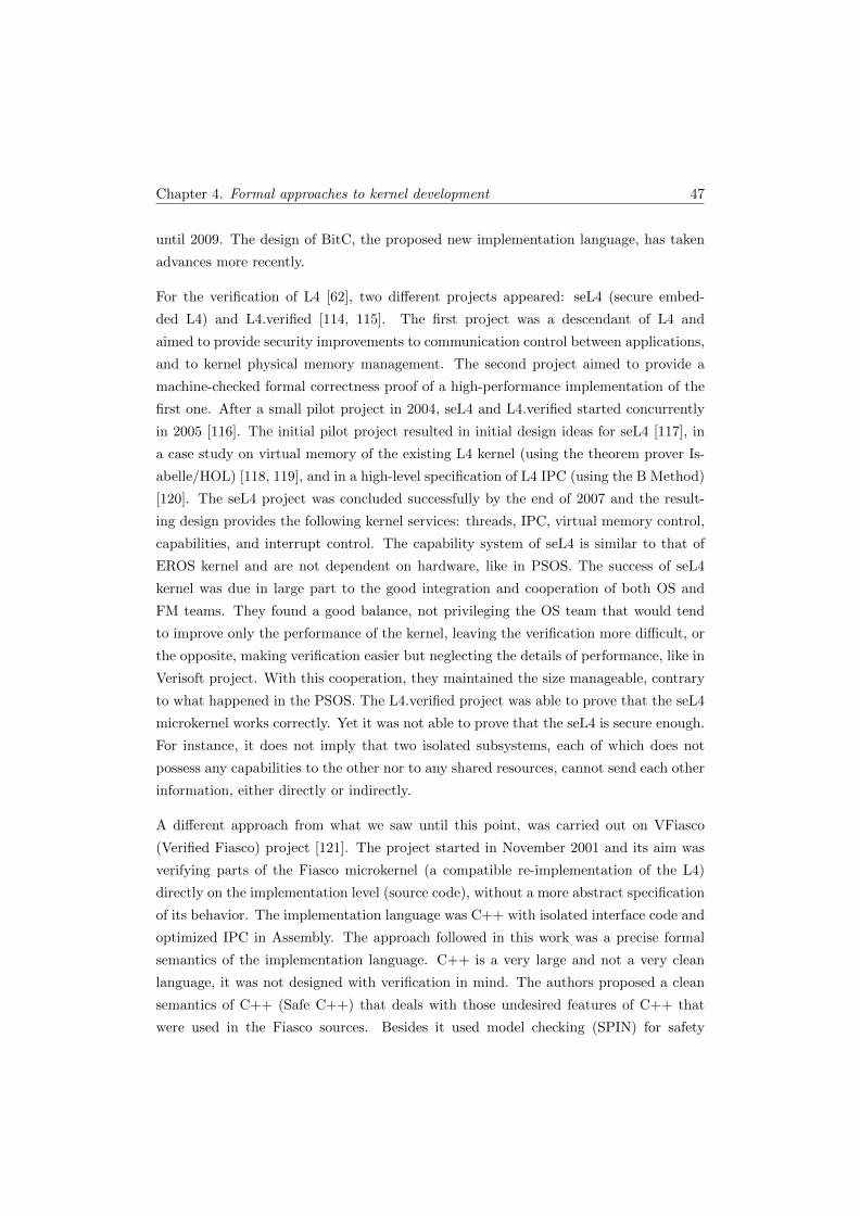
Chapter 4. Formal approaches to kernel development 47
until 2009. The design of BitC, the proposed new implementation language, has taken
advances more recently.
For the verification of L4 [62], two different projects appeared: seL4 (secure embed-
ded L4) and L4.verified [114, 115]. The first project was a descendant of L4 and
aimed to provide security improvements to communication control between applications,
and to kernel physical memory management. The second project aimed to provide a
machine-checked formal correctness proof of a high-performance implementation of the
first one. After a small pilot project in 2004, seL4 and L4.verified started concurrently
in 2005 [116]. The initial pilot project resulted in initial design ideas for seL4 [117], in
a case study on virtual memory of the existing L4 kernel (using the theorem prover Is-
abelle/HOL) [118, 119], and in a high-level specification of L4 IPC (using the B Method)
[120]. The seL4 project was concluded successfully by the end of 2007 and the result-
ing design provides the following kernel services: threads, IPC, virtual memory control,
capabilities, and interrupt control. The capability system of seL4 is similar to that of
EROS kernel and are not dependent on hardware, like in PSOS. The success of seL4
kernel was due in large part to the good integration and cooperation of both OS and
FM teams. They found a good balance, not privileging the OS team that would tend
to improve only the performance of the kernel, leaving the verification more difficult, or
the opposite, making verification easier but neglecting the details of performance, like in
Verisoft project. With this cooperation, they maintained the size manageable, contrary
to what happened in the PSOS. The L4.verified project was able to prove that the seL4
microkernel works correctly. Yet it was not able to prove that the seL4 is secure enough.
For instance, it does not imply that two isolated subsystems, each of which does not
possess any capabilities to the other nor to any shared resources, cannot send each other
information, either directly or indirectly.
A different approach from what we saw until this point, was carried out on VFiasco
(Verified Fiasco) project [121]. The project started in November 2001 and its aim was
verifying parts of the Fiasco microkernel (a compatible re-implementation of the L4)
directly on the implementation level (source code), without a more abstract specification
of its behavior. The implementation language was C++ with isolated interface code and
optimized IPC in Assembly. The approach followed in this work was a precise formal
semantics of the implementation language. C++ is a very large and not a very clean
language, it was not designed with verification in mind. The authors proposed a clean
semantics of C++ (Safe C++) that deals with those undesired features of C++ that
were used in the Fiasco sources. Besides it used model checking (SPIN) for safety

Chapter 4. Formal approaches to kernel development 48
properties on the IPC, the verification was made in the interactive theorem provers
Isabelle/HOL and PVS. They proved some object-store properties, such as: a) writing
to some allocated object does not accidentally modify any other allocated object; b)
after writing to an allocated object, reading from that object actually returns the value
written; and c) the order in which you allocate or deallocate objects is irrelevant as long
as you deallocate objects with the same allocator used in the first place. Nevertheless,
the verification was achieved only by a small portion of the implementation.
The ROBIN (Open Robust Infrastructures) project continued the VFiasco approach
to C++ source code verification [122, 123]. The project started in February 2006 and
aimed to investigate the verification of the Nova hypervisor, an L4-based kernel, this
is a different microkernel for OS virtualization. The project ended in April 2008 and
produced about 70% of a high-level specification for the Nova kernel [123]. Like what
happened with Vfiasco, this project also not achieved a verification of a considerable
part of the implementation.
This section is summarized in Table 4.1. The first column shows the name of the projects.
The next two columns show, respectively, the year when the project was made (years
between parentheses represent an estimation) and the specification language used in the
project. The fourth column identifies the use of model checking technique, and the next
two columns identify the amount of proofs achieved in the project and also the theorem
prover used for that. Finally, the last column shows whether the project achieved the
implementation level. The projects included in this table have different purposes: a)
PSOS and Verisoft aimed to verify the whole system; b) the complete kernel verification
was the purpose of UCLA Secure Unix, KIT, and L4.verified/seL4; c) the remaining
projects aimed to verify only specific parts of the kernel. Another aspect, is the use
of data refinement approach; this method was followed by UCLA Secure Unix, KIT,
Verisoft, and L4.verified/seL4; this method was not used in the remaining projects.

Chapter 4. Formal approaches to kernel development 49
YearsSpecification
Language
Model
CheckingProofs
Theorem
ProverImplemented
PSOS 1973-1983 SPECIAL - - - partial
UCLA
Secure Unix<1977-1980
Pascal
(extended)- <20% XIVUS partial
KIT ?-1987Boyer-Moore
logic- yes
Boyer-
MooreAssembly
RUBIS 1995 PROMELA SPIN - -already
implemented
SELinux 2000-2002 TAME NuSMV few PVSalready
implemented
VFiasco/
ROBIN2001-2008 - SPIN few
Isabelle/HOL
and PVS
C++ (already
implemented)
Verisoft 2003-(2010)Isabelle
specification-
about
50%
Isabelle/HOL
and PVSC0
L4.verified/
seL42005-(2011) Haskell - yes Isabelle/HOL C/Assembly
Table 4.1: Traditional kernels verification - adapted from [77].
4.2 Separation kernels
As seen in Section 3.2, the separation kernel was introduced in the early 80’s [65, 124],
but only a few years later - given the need of such system - the concept was rediscovered.
Since this is a more specific type of kernel, there is less work available in the literature.
Below we will present some of the most relevant work reviewed.
One of the first works that appeared in the literature was a safety kernel for traffic
light control [125]. The work used a realistic example to show the possibility of imple-
menting a Rushby kernel. Properties of the system were specified in Z notation and an
implementation of the kernel written in Ada was proposed.
The Mathematically Analyzed Separation Kernel (MASK) [126, 127] emerged in the
current century. The MASK was designed and built using Specware [128]. The authors
started from high-level model and down to reach a low-level design, which was close
to an implementation with multiple formal refinement proofs. This low-level design
was manually translated into C and reviewed against the Specware models. Its main
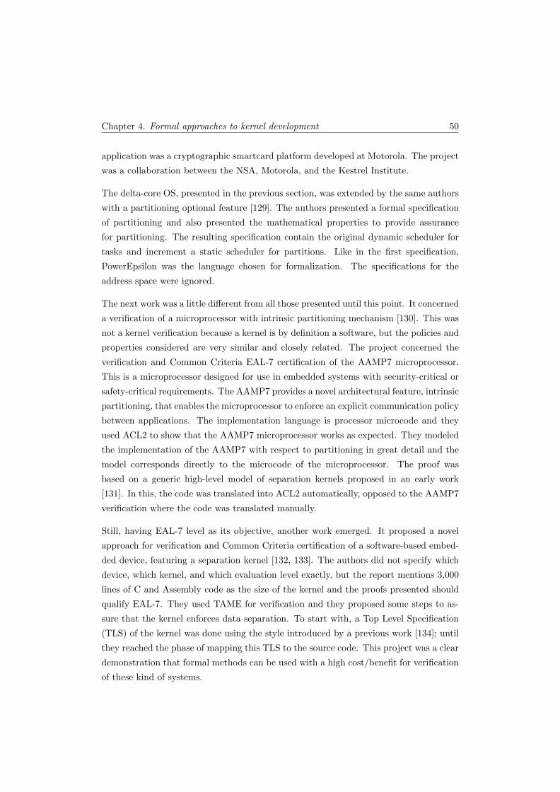
Chapter 4. Formal approaches to kernel development 50
application was a cryptographic smartcard platform developed at Motorola. The project
was a collaboration between the NSA, Motorola, and the Kestrel Institute.
The delta-core OS, presented in the previous section, was extended by the same authors
with a partitioning optional feature [129]. The authors presented a formal specification
of partitioning and also presented the mathematical properties to provide assurance
for partitioning. The resulting specification contain the original dynamic scheduler for
tasks and increment a static scheduler for partitions. Like in the first specification,
PowerEpsilon was the language chosen for formalization. The specifications for the
address space were ignored.
The next work was a little different from all those presented until this point. It concerned
a verification of a microprocessor with intrinsic partitioning mechanism [130]. This was
not a kernel verification because a kernel is by definition a software, but the policies and
properties considered are very similar and closely related. The project concerned the
verification and Common Criteria EAL-7 certification of the AAMP7 microprocessor.
This is a microprocessor designed for use in embedded systems with security-critical or
safety-critical requirements. The AAMP7 provides a novel architectural feature, intrinsic
partitioning, that enables the microprocessor to enforce an explicit communication policy
between applications. The implementation language is processor microcode and they
used ACL2 to show that the AAMP7 microprocessor works as expected. They modeled
the implementation of the AAMP7 with respect to partitioning in great detail and the
model corresponds directly to the microcode of the microprocessor. The proof was
based on a generic high-level model of separation kernels proposed in an early work
[131]. In this, the code was translated into ACL2 automatically, opposed to the AAMP7
verification where the code was translated manually.
Still, having EAL-7 level as its objective, another work emerged. It proposed a novel
approach for verification and Common Criteria certification of a software-based embed-
ded device, featuring a separation kernel [132, 133]. The authors did not specify which
device, which kernel, and which evaluation level exactly, but the report mentions 3,000
lines of C and Assembly code as the size of the kernel and the proofs presented should
qualify EAL-7. They used TAME for verification and they proposed some steps to as-
sure that the kernel enforces data separation. To start with, a Top Level Specification
(TLS) of the kernel was done using the style introduced by a previous work [134]; until
they reached the phase of mapping this TLS to the source code. This project was a clear
demonstration that formal methods can be used with a high cost/benefit for verification
of these kind of systems.
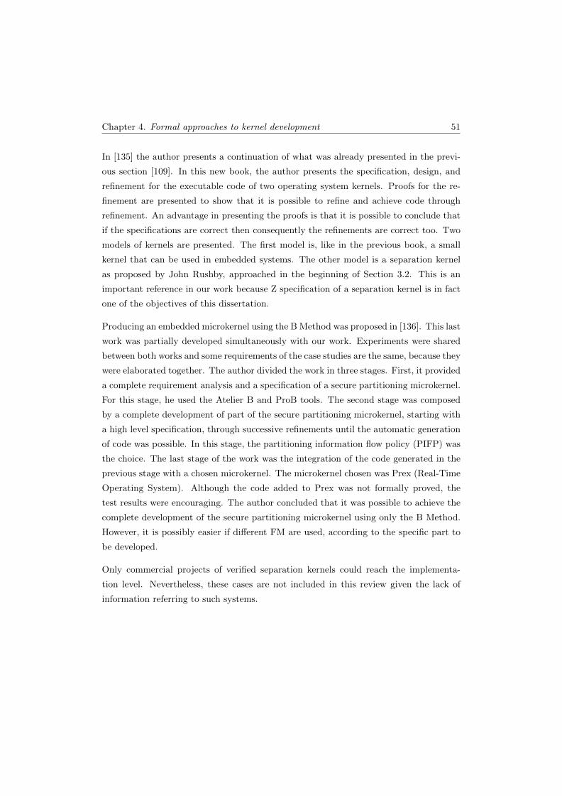
Chapter 4. Formal approaches to kernel development 51
In [135] the author presents a continuation of what was already presented in the previ-
ous section [109]. In this new book, the author presents the specification, design, and
refinement for the executable code of two operating system kernels. Proofs for the re-
finement are presented to show that it is possible to refine and achieve code through
refinement. An advantage in presenting the proofs is that it is possible to conclude that
if the specifications are correct then consequently the refinements are correct too. Two
models of kernels are presented. The first model is, like in the previous book, a small
kernel that can be used in embedded systems. The other model is a separation kernel
as proposed by John Rushby, approached in the beginning of Section 3.2. This is an
important reference in our work because Z specification of a separation kernel is in fact
one of the objectives of this dissertation.
Producing an embedded microkernel using the B Method was proposed in [136]. This last
work was partially developed simultaneously with our work. Experiments were shared
between both works and some requirements of the case studies are the same, because they
were elaborated together. The author divided the work in three stages. First, it provided
a complete requirement analysis and a specification of a secure partitioning microkernel.
For this stage, he used the Atelier B and ProB tools. The second stage was composed
by a complete development of part of the secure partitioning microkernel, starting with
a high level specification, through successive refinements until the automatic generation
of code was possible. In this stage, the partitioning information flow policy (PIFP) was
the choice. The last stage of the work was the integration of the code generated in the
previous stage with a chosen microkernel. The microkernel chosen was Prex (Real-Time
Operating System). Although the code added to Prex was not formally proved, the
test results were encouraging. The author concluded that it was possible to achieve the
complete development of the secure partitioning microkernel using only the B Method.
However, it is possibly easier if different FM are used, according to the specific part to
be developed.
Only commercial projects of verified separation kernels could reach the implementa-
tion level. Nevertheless, these cases are not included in this review given the lack of
information referring to such systems.

Chapter 4. Formal approaches to kernel development 52
4.3 Tokeneer project
As mentioned above, the methodology used in this MSc work was based on the method-
ology that was used in the Tokeneer project, in a more simple way though imposed by
our somewhat limited experience to perform the various steps. The Tokeneer project was
carried out by Praxis and consisted of a re-development of the original work developed
by the NSA (National Security Agency).
The project arose from a proposal made by the NSA to Praxis with the following objec-
tives: a) to demonstrate that it is possible to develop highly secure systems in accordance
to the highest security levels of Common Criteria; b) to show that it is possible to develop
safe systems of a rigorous manner and simultaniously in a cost-effective manner.
The system consists of a secure enclave with controlled physical entry. Within the
enclave, there are various workstations and the users must pass security tests in order to
access the machines. The security tests are done with the presentation of a token (e.g.
smart-card) into a reader that is outside the enclave. The system uses the information
of the token to carry out biometric tests (e.g. fingerprint reading) of the user. If both
informations are matched, then the enclave door opens giving access to the user. At the
same time, the system checks what type of access is allowed for this user. The physical
devices are replaced by test drivers to avoid licensing issues and to ease testing. They
were developed by SPRE Inc. on a separate machine.
The development of the system was made according to Praxis CbyC process, containing
the following phases:
1. Requirements analysis (the REVEAL process);
2. Formal specification (Z notation);
3. Design (refinement of the specification and INFORMED process);
4. Implementation in SPARK;
5. Verification (SPARK Examiner toolset);
6. Top-down system testing.
The Tokeneer project material was released in July 2008 as a contribution to the Verified
Software Grand Challenge. It achieved EAL-5 in areas of development like configuration
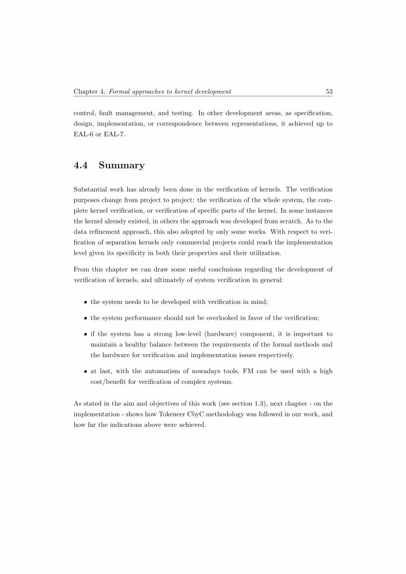
Chapter 4. Formal approaches to kernel development 53
control, fault management, and testing. In other development areas, as specification,
design, implementation, or correspondence between representations, it achieved up to
EAL-6 or EAL-7.
4.4 Summary
Substantial work has already been done in the verification of kernels. The verification
purposes change from project to project: the verification of the whole system, the com-
plete kernel verification, or verification of specific parts of the kernel. In some instances
the kernel already existed, in others the approach was developed from scratch. As to the
data refinement approach, this also adopted by only some works. With respect to veri-
fication of separation kernels only commercial projects could reach the implementation
level given its specificity in both their properties and their utilization.
From this chapter we can draw some useful conclusions regarding the development of
verification of kernels, and ultimately of system verification in general:
• the system needs to be developed with verification in mind;
• the system performance should not be overlooked in favor of the verification;
• if the system has a strong low-level (hardware) component, it is important to
maintain a healthy balance between the requirements of the formal methods and
the hardware for verification and implementation issues respectively.
• at last, with the automatism of nowadays tools, FM can be used with a high
cost/benefit for verification of complex systems.
As stated in the aim and objectives of this work (see section 1.3), next chapter - on the
implementation - shows how Tokeneer CbyC methodology was followed in our work, and
how far the indications above were achieved.
Chapter 5
Implementation
In this chapter we show the implementation of the case study presented in Chapter 3
with the SPARK and the method proposed above in Chapter 2.
The project is based on an existing proposal and hence the functional requirements had
been almost defined. Even so, some changes had to be made in order to meet our specific
needs. Only the fundamental security requirements of the system are emphasized in here,
with special relevance to the three main properties described in the previous chapter:
• Spatial partitioning: each partition can only access its own memory (information),
the remainder memory is inaccessible;
• Temporal partitioning: a partition controls only the hardware during a given time.
Once this time is over, the partition has no longer control over the hardware, which
will be then controlled by another partition;
• Security partitioning: the communication between partitions is established safely.
Communication’s contents are only shared by partitions involved in the communi-
cation process.
The list of the requirements is presented in Appendix A.
After the survey of requirements and with a set of requirements well-defined, we passed
on to the implementation following the development cycle proposed above and shown in
Figure 5.1.
54
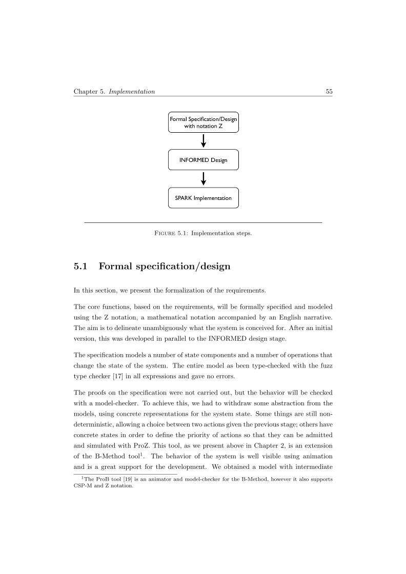
Chapter 5. Implementation 55
Figure 5.1: Implementation steps.
5.1 Formal specification/design
In this section, we present the formalization of the requirements.
The core functions, based on the requirements, will be formally specified and modeled
using the Z notation, a mathematical notation accompanied by an English narrative.
The aim is to delineate unambiguously what the system is conceived for. After an initial
version, this was developed in parallel to the INFORMED design stage.
The specification models a number of state components and a number of operations that
change the state of the system. The entire model as been type-checked with the fuzz
type checker [17] in all expressions and gave no errors.
The proofs on the specification were not carried out, but the behavior will be checked
with a model-checker. To achieve this, we had to withdraw some abstraction from the
models, using concrete representations for the system state. Some things are still non-
deterministic, allowing a choice between two actions given the previous stage; others have
concrete states in order to define the priority of actions so that they can be admitted
and simulated with ProZ. This tool, as we present above in Chapter 2, is an extension
of the B-Method tool1. The behavior of the system is well visible using animation
and is a great support for the development. We obtained a model with intermediate
1The ProB tool [19] is an animator and model-checker for the B-Method, however it also supportsCSP-M and Z notation.
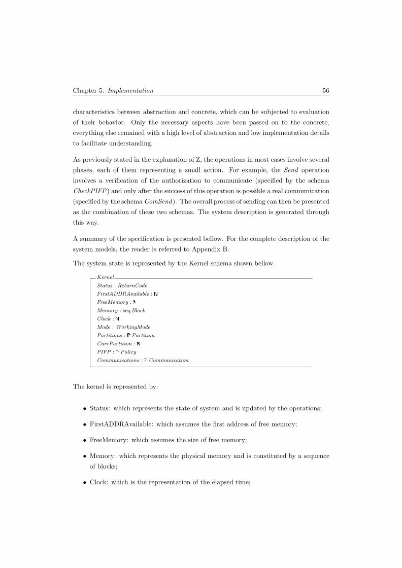
Chapter 5. Implementation 56
characteristics between abstraction and concrete, which can be subjected to evaluation
of their behavior. Only the necessary aspects have been passed on to the concrete,
everything else remained with a high level of abstraction and low implementation details
to facilitate understanding.
As previously stated in the explanation of Z, the operations in most cases involve several
phases, each of them representing a small action. For example, the Send operation
involves a verification of the authorization to communicate (specified by the schema
CheckPIFP) and only after the success of this operation is possible a real communication
(specified by the schema ComSend). The overall process of sending can then be presented
as the combination of these two schemas. The system description is generated through
this way.
A summary of the specification is presented bellow. For the complete description of the
system models, the reader is referred to Appendix B.
The system state is represented by the Kernel schema shown bellow.
Kernel
Status : ReturnCode
FirstADDRAvailable :
FreeMemory :
Memory : seqBlock
Clock :
Mode : WorkingMode
Partitions : �Partition
CurrPartition :
PIFP : �Policy
Communications : �Communication
The kernel is represented by:
• Status: which represents the state of system and is updated by the operations;
• FirstADDRAvailable: which assumes the first address of free memory;
• FreeMemory: which assumes the size of free memory;
• Memory: which represents the physical memory and is constituted by a sequence
of blocks;
• Clock: which is the representation of the elapsed time;
Chapter 5. Implementation 57
• Mode: which shows the working mode allowed at a given moment;
• Partitions: a set with the system partitions;
• CurrPartition: which represents the running partition;
• PIFP: a set that contains the communication policies for all system partitions;
• Communications: a set that contains the communications performed by the sys-
tem.
The enabled operations are:
• Start: this performs an initialization of the system;
• ContextSwitch: which changes the execution partition of the system when its time
is exhausted;
• ReadWrite: which performs a read or write operation (it tries the access to a
memory space);
• Send: which performs a communication to send a message;
• Receive: which performs a communication to receive a message;
• Tick: as the purpose to give a tick of the clock CPU generating an interruption
and, changing the kernel to privileged mode.
The main differences between the specification hereby proposed and some of the ones
available in the literature (e.g. [109, 135]), is the simple way in which they are developed
and yet still covering the requirements for the purposes established. The communication
mechanism implemented in our system has its own particularities different from the oth-
ers. These have to do principally with the need to meet a pre-established communication
security police.
Ideally, we should have two types of models. First, a formal specification of the system
with black-box behavior; second, a formal design which is a refinement of the first
model, but with implementation details. The objective is to separate the external visible
behavior of its internal design. This was not the approach followed since we wanted
something simpler and more high level for the perception of the system and its behavior.
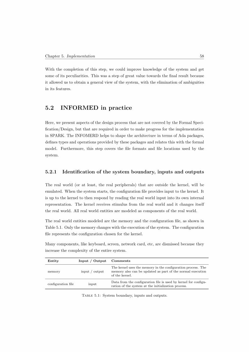
Chapter 5. Implementation 58
With the completion of this step, we could improve knowledge of the system and get
some of its peculiarities. This was a step of great value towards the final result because
it allowed us to obtain a general view of the system, with the elimination of ambiguities
in its features.
5.2 INFORMED in practice
Here, we present aspects of the design process that are not covered by the Formal Speci-
fication/Design, but that are required in order to make progress for the implementation
in SPARK. The INFOMERD helps to shape the architecture in terms of Ada packages,
defines types and operations provided by these packages and relates this with the formal
model. Furthermore, this step covers the file formats and file locations used by the
system.
5.2.1 Identification of the system boundary, inputs and outputs
The real world (or at least, the real peripherals) that are outside the kernel, will be
emulated. When the system starts, the configuration file provides input to the kernel. It
is up to the kernel to then respond by reading the real world input into its own internal
representation. The kernel receives stimulus from the real world and it changes itself
the real world. All real world entities are modeled as components of the real world.
The real world entities modeled are the memory and the configuration file, as shown in
Table 5.1. Only the memory changes with the execution of the system. The configuration
file represents the configuration chosen for the kernel.
Many components, like keyboard, screen, network card, etc, are dismissed because they
increase the complexity of the entire system.
Entity Input / Output Comments
memory input / outputThe kernel uses the memory in the configuration process. Thememory also can be updated as part of the normal executionof the kernel.
configuration file inputData from the configuration file is used by kernel for configu-ration of the system at the initialization process.
Table 5.1: System boundary, inputs and outputs.
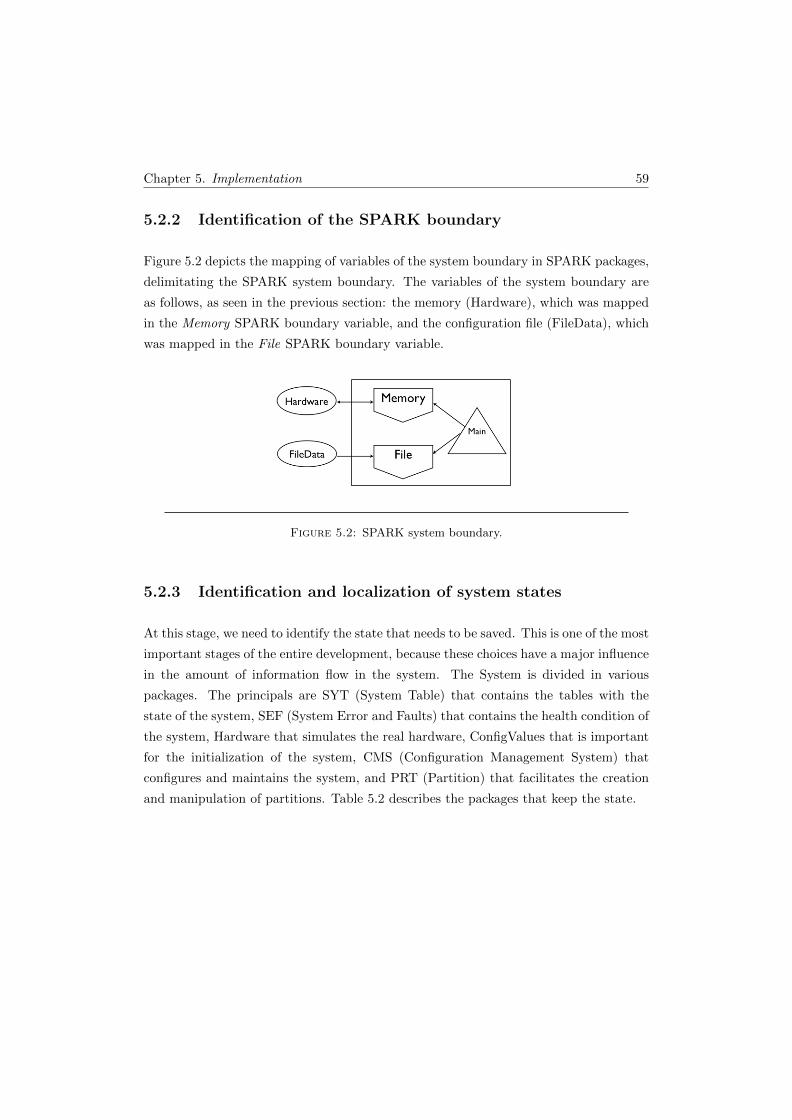
Chapter 5. Implementation 59
5.2.2 Identification of the SPARK boundary
Figure 5.2 depicts the mapping of variables of the system boundary in SPARK packages,
delimitating the SPARK system boundary. The variables of the system boundary are
as follows, as seen in the previous section: the memory (Hardware), which was mapped
in the Memory SPARK boundary variable, and the configuration file (FileData), which
was mapped in the File SPARK boundary variable.
Figure 5.2: SPARK system boundary.
5.2.3 Identification and localization of system states
At this stage, we need to identify the state that needs to be saved. This is one of the most
important stages of the entire development, because these choices have a major influence
in the amount of information flow in the system. The System is divided in various
packages. The principals are SYT (System Table) that contains the tables with the
state of the system, SEF (System Error and Faults) that contains the health condition of
the system, Hardware that simulates the real hardware, ConfigValues that is important
for the initialization of the system, CMS (Configuration Management System) that
configures and maintains the system, and PRT (Partition) that facilitates the creation
and manipulation of partitions. Table 5.2 describes the packages that keep the state.
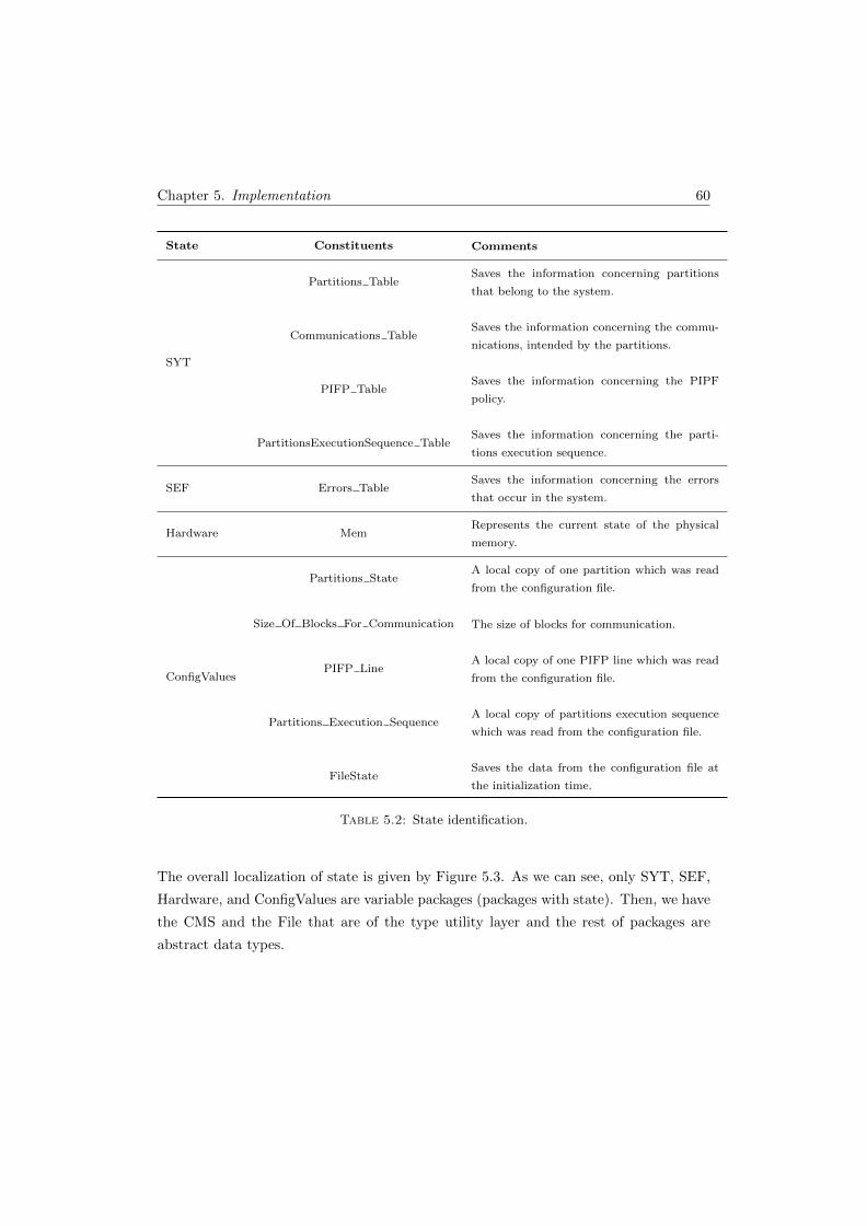
Chapter 5. Implementation 60
State Constituents Comments
SYT
Partitions TableSaves the information concerning partitions
that belong to the system.
Communications TableSaves the information concerning the commu-
nications, intended by the partitions.
PIFP TableSaves the information concerning the PIPF
policy.
PartitionsExecutionSequence TableSaves the information concerning the parti-
tions execution sequence.
SEF Errors TableSaves the information concerning the errors
that occur in the system.
Hardware MemRepresents the current state of the physical
memory.
ConfigValues
Partitions StateA local copy of one partition which was read
from the configuration file.
Size Of Blocks For Communication The size of blocks for communication.
PIFP LineA local copy of one PIFP line which was read
from the configuration file.
Partitions Execution SequenceA local copy of partitions execution sequence
which was read from the configuration file.
FileStateSaves the data from the configuration file at
the initialization time.
Table 5.2: State identification.
The overall localization of state is given by Figure 5.3. As we can see, only SYT, SEF,
Hardware, and ConfigValues are variable packages (packages with state). Then, we have
the CMS and the File that are of the type utility layer and the rest of packages are
abstract data types.
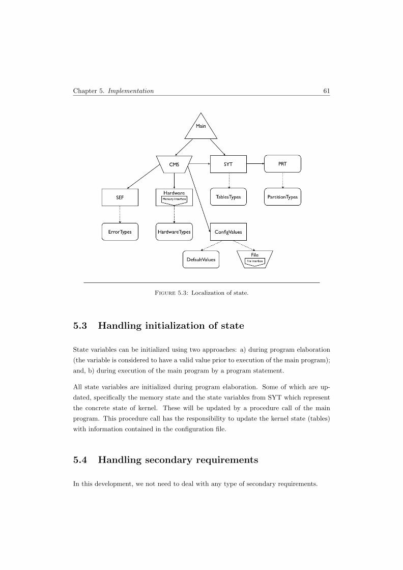
Chapter 5. Implementation 61
Figure 5.3: Localization of state.
5.3 Handling initialization of state
State variables can be initialized using two approaches: a) during program elaboration
(the variable is considered to have a valid value prior to execution of the main program);
and, b) during execution of the main program by a program statement.
All state variables are initialized during program elaboration. Some of which are up-
dated, specifically the memory state and the state variables from SYT which represent
the concrete state of kernel. These will be updated by a procedure call of the main
program. This procedure call has the responsibility to update the kernel state (tables)
with information contained in the configuration file.
5.4 Handling secondary requirements
In this development, we not need to deal with any type of secondary requirements.

Chapter 5. Implementation 62
5.5 Implementing the internal behavior of compo-
nents
The facilities provided by each of the library level packages in the system, the correspon-
dence with Z models (that can be found in Appendix B), and the respective references to
the requirements (that can be founded in Appendix A) are summarized in this section.
We show the specifications of the packages. The specifications are presented with anno-
tations, allowing an early static analysis of the design. The specifications presented con-
tain the Ada signature for the operations and its annotations, which include the global
state used or modified by the operation (the global clause) and the relationship between
the global state and the operation parameters (the derives clause). Some functions and
procedures are specified with proof annotations. After the specification packages are
completed, body packages with implementation of operations are developed. Here, only
the specifications are shown, the complete code can be found in Appendix C.
DefaultValues
In the DefaultValues package, there are some default values for the configuration of the
system, such as the name and the path for the configuration file of the system or the
value of memory size that can been handled by the system.
PartitionTypes
The PartitionTypes package contains the types needed for the partitions, which were
used in the PRT package. All of the types are presented in Table 5.3 and are described
below with more detail.
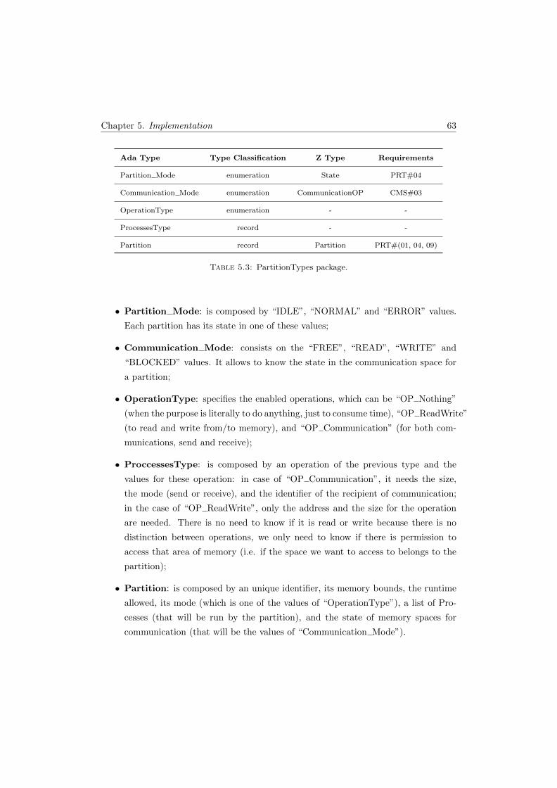
Chapter 5. Implementation 63
Ada Type Type Classification Z Type Requirements
Partition Mode enumeration State PRT#04
Communication Mode enumeration CommunicationOP CMS#03
OperationType enumeration - -
ProcessesType record - -
Partition record Partition PRT#(01, 04, 09)
Table 5.3: PartitionTypes package.
• Partition Mode: is composed by “IDLE”, “NORMAL” and “ERROR” values.
Each partition has its state in one of these values;
• Communication Mode: consists on the “FREE”, “READ”, “WRITE” and
“BLOCKED” values. It allows to know the state in the communication space for
a partition;
• OperationType: specifies the enabled operations, which can be “OP Nothing”
(when the purpose is literally to do anything, just to consume time), “OP ReadWrite”
(to read and write from/to memory), and “OP Communication” (for both com-
munications, send and receive);
• ProccessesType: is composed by an operation of the previous type and the
values for these operation: in case of “OP Communication”, it needs the size,
the mode (send or receive), and the identifier of the recipient of communication;
in the case of “OP ReadWrite”, only the address and the size for the operation
are needed. There is no need to know if it is read or write because there is no
distinction between operations, we only need to know if there is permission to
access that area of memory (i.e. if the space we want to access to belongs to the
partition);
• Partition: is composed by an unique identifier, its memory bounds, the runtime
allowed, its mode (which is one of the values of “OperationType”), a list of Pro-
cesses (that will be run by the partition), and the state of memory spaces for
communication (that will be the values of “Communication Mode”).

Chapter 5. Implementation 64
PRT
The PRT package has the function to create and manipulate partitions. It has the
operations summarized in Table 5.4.
Ada Operation Operation Type Z Operation Requirements
GetID function - PRT#04
GetDuration function GetDuration PRT#03
GetPartitionMode function - PRT#03
SetPartitionMode procedure
PartitionResumes,
PartitionSuspends,
CurrPartitionError
PRT#03
Init procedure NewPartition PRT#02
ClearCommunicationList procedure - PRT#03
Table 5.4: PRT package.
Only the “partition mode” has a setter (Code Listing 5.2), this is the unique label that
can be subsequently updated. The labels “ID”, “duration” and “mode” have a getter
function (Code Listing 5.1) that retrieves its values.
�5 function GetID (P : Part i t ionTypes . P a r t i t i o n ) return Par t i t i on type s . IdType ;
6 --# return P. ID ;
7
8 function GetDuration (P : Part i t ionTypes . P a r t i t i o n ) return ←↩
Part i t ionTypes . Par t i t i on Dura t i on ;
9 --# return P. Duration ;
10
11 function GetPartitionMode (P : Part i t ionTypes . P a r t i t i o n ) return ←↩
Part i t ionTypes . Part it ion Mode ;
12 --# return P. Mode ;� Code Listing 5.1: PRT specification package (GetID, GetDuration and
GetPartitionMode functions)
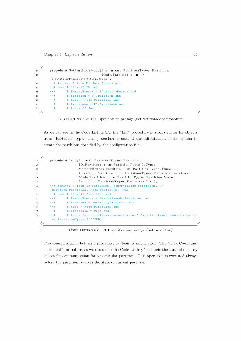
Chapter 5. Implementation 65
�14 procedure SetPart it ionMode (P : in out Part i t ionTypes . P a r t i t i o n ;
15 Mode Part it ion : in ←↩
Part i t ionTypes . Part it ion Mode ) ;
16 --# derives P from P , Mode_Partition ;
17 --# post P. ID = P ~. ID and
18 --# P. MemoryBounds = P ~. MemoryBounds and
19 --# P. Duration = P ~. Duration and
20 --# P. Mode = Mode_Partition and
21 --# P. Processes = P ~. Processes and
22 --# P. Com = P ~. Com ;� Code Listing 5.2: PRT specification package (SetPartitionMode procedure)
As we can see in the Code Listing 5.3, the “Init” procedure is a constructor for objects
from “Partition” type. This procedure is used at the initialization of the system to
create the partitions specified by the configuration file.
�24 procedure I n i t (P : out Part i t ionTypes . P a r t i t i o n ;
25 ID Par t i t i on : in Part i t ionTypes . IdType ;
26 MemoryBounds Partition : in Part i t ionTypes . Tuple ;
27 Durat i on Par t i t i on : in Part i t ionTypes . Par t i t i on Dura t i on ;
28 Mode Part it ion : in Part i t ionTypes . Part it ion Mode ;
29 Proc : in Part i t ionTypes . P r o c e s s e s L i s t ) ;
30 --# derives P from ID_Partition , MemoryBounds_Partition , ←↩
Duration_Partition , Mode_Partition , Proc ;
31 --# post P. ID = ID_Partition and
32 --# P. MemoryBounds = MemoryBounds_Partition and
33 --# P. Duration = Duration_Partition and
34 --# P. Mode = Mode_Partition and
35 --# P. Processes = Proc and
36 --# P. Com = PartitionTypes . Communication ’( PartitionTypes . Index_Range ←↩
=> PartitionTypes . BLOCKED );� Code Listing 5.3: PRT specification package (Init procedure)
The communication list has a procedure to clean its information. The “ClearCommuni-
cationList” procedure, as we can see in the Code Listing 5.4, resets the state of memory
spaces for communication for a particular partition. This operation is executed always
before the partition receives the state of current partition.
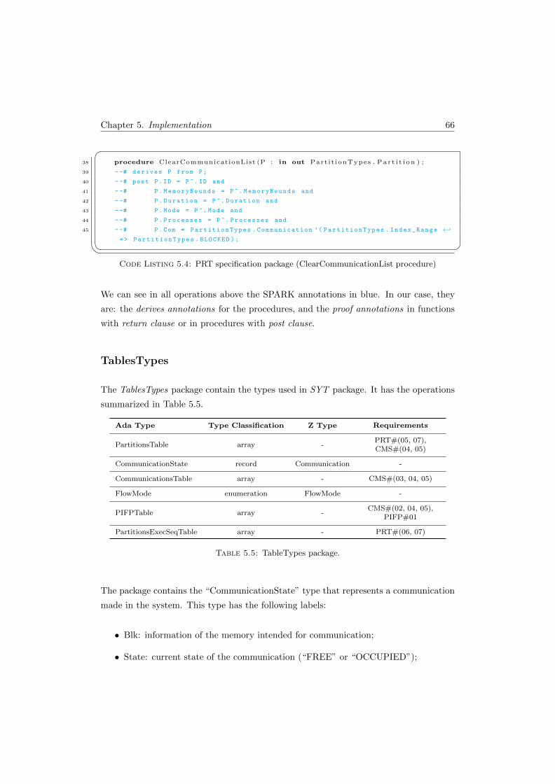
Chapter 5. Implementation 66
�38 procedure ClearCommunicationList (P : in out Part i t ionTypes . P a r t i t i o n ) ;
39 --# derives P from P;
40 --# post P. ID = P ~. ID and
41 --# P. MemoryBounds = P ~. MemoryBounds and
42 --# P. Duration = P ~. Duration and
43 --# P. Mode = P ~. Mode and
44 --# P. Processes = P ~. Processes and
45 --# P. Com = PartitionTypes . Communication ’( PartitionTypes . Index_Range ←↩
=> PartitionTypes . BLOCKED );� Code Listing 5.4: PRT specification package (ClearCommunicationList procedure)
We can see in all operations above the SPARK annotations in blue. In our case, they
are: the derives annotations for the procedures, and the proof annotations in functions
with return clause or in procedures with post clause.
TablesTypes
The TablesTypes package contain the types used in SYT package. It has the operations
summarized in Table 5.5.
Ada Type Type Classification Z Type Requirements
PartitionsTable array -PRT#(05, 07),CMS#(04, 05)
CommunicationState record Communication -
CommunicationsTable array - CMS#(03, 04, 05)
FlowMode enumeration FlowMode -
PIFPTable array -CMS#(02, 04, 05),
PIFP#01
PartitionsExecSeqTable array - PRT#(06, 07)
Table 5.5: TableTypes package.
The package contains the “CommunicationState” type that represents a communication
made in the system. This type has the following labels:
• Blk: information of the memory intended for communication;
• State: current state of the communication (“FREE” or “OCCUPIED”);

Chapter 5. Implementation 67
• From Partition and To Partition: identifiers of the partitions involved in the com-
munication;
• Mode: type of communication, i.e. send (“WRITE”) or receive (“READ”);
• FreeSize: free size of its memory (enables the use of all blocks of communication).
�1 with DefaultValues , Part i t ionTypes ;
2 --# inherit DefaultValues , PartitionTypes ;
3 package TablesTypes i s
4
5 type Par t i t i on sTab l e i s array ( Part i t ionTypes . Partit ionsNumber ) of ←↩
Part i t ionTypes . P a r t i t i o n ;
6
7 type Blocks Sta te i s (FREE, OCCUPIED) ;
8
9 type TupleCommunication i s record
10 i n i t : Part i t ionTypes . AddrAllowValues ;
11 sz : Part i t ionTypes . CommunicationsBlockSizeAllowValues ;
12 end record ;
13
14 type CommunicationState i s record
15 Blk : TupleCommunication ;
16 State : B locks Sta te ;
17 From Part i t ion : Part i t ionTypes . IdType ;
18 To Part i t i on : Part i t ionTypes . Partit ionsNumber ;
19 Mode : Part i t ionTypes . CommunicationMode ;
20 FreeS i ze : Natural ;
21 end record ;
22
23 subtype CommunicationsBlocksNumber i s I n t eg e r range 1 . . ←↩
DefaultValues . Number Of Communications Blocks ;
24
25 type CommunicationsTable i s array ( CommunicationsBlocksNumber ) of ←↩
CommunicationState ;
26
27 type FlowMode i s (R, W, RW, N) ;
28
29 type P a r t i t i o n s i s array ( Part i t ionTypes . Partit ionsNumber ) of FlowMode ;
30
31 type PIFPTable i s array ( Part i t ionTypes . Partit ionsNumber ) of P a r t i t i o n s ;
32
33 subtype Part i t i onsExecut ionIndex i s I n t eg e r range 1 . . ←↩
DefaultValues . Partit ionsExecutionNumber ;
34
35 type Part i t ionsExecut ionSequenceTable i s array ( Par t i t i onsExecut ionIndex ) ←↩
of Part i t ionTypes . Partit ionsNumber ;
36
37 end TablesTypes ;� Code Listing 5.5: TablesTypes specification package

Chapter 5. Implementation 68
It also contains the “FlowMode” type, that allows the control of the communications;
this is constituted by “R”, “W”, “RW”, “N”, respectively, read, write, read and write,
and none.
The package contains four types of tables. The “PartitionsTable”, as we can see in
Code Listing 5.5, is an array of the “Partition” type, its dimension depends on the
number of partitions specified for the system. The “CommunicationsTable” is an array
of the “CommunicationState” type, its dimension depends on the number of blocks for
communication specified for the system. The “PIFPTable” is an array of “FlowMode”
type, its dimension, one more time, depends on the number of partitions specified for
the system. Finally, the “PartitionsExecutionSequenceTable” is an array of “Partition-
Types.PartitionNumber” (this type represents the “ID” of one partition) and its dimen-
sion depends on the value of “DefaultValues.PartitionsExecutionNumber” specified for
the system.
HardwareTypes
In this package we have the representation of the physical memory which contains a
description of the state of the system memory. The memory is divided into blocks and
each block contains the starting address, the size and its state, which can be either free
or occupied.
ErrorTypes
This package contains the types of errors and the facilities necessary for the SEF package.
It has the operations summarized in Table 5.6.
Ada Type Type Classification Z Type Requirements
Faults enumeration - SEF#(01, 02), SYT#02
State enumeration - -
ErrorsTable array - SEF#02, SYT#02
Table 5.6: ErrorTypes package.
The “Faults” type represents the different sorts of errors, which can take the following
values:
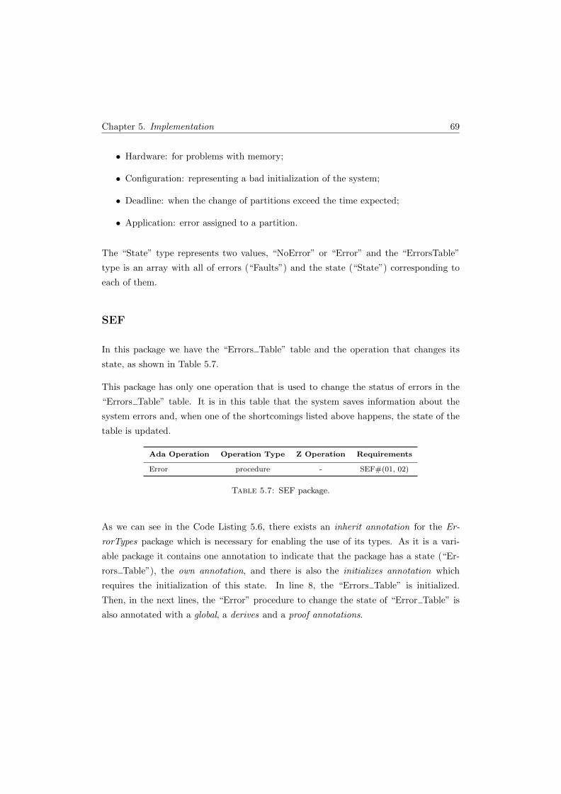
Chapter 5. Implementation 69
• Hardware: for problems with memory;
• Configuration: representing a bad initialization of the system;
• Deadline: when the change of partitions exceed the time expected;
• Application: error assigned to a partition.
The “State” type represents two values, “NoError” or “Error” and the “ErrorsTable”
type is an array with all of errors (“Faults”) and the state (“State”) corresponding to
each of them.
SEF
In this package we have the “Errors Table” table and the operation that changes its
state, as shown in Table 5.7.
This package has only one operation that is used to change the status of errors in the
“Errors Table” table. It is in this table that the system saves information about the
system errors and, when one of the shortcomings listed above happens, the state of the
table is updated.
Ada Operation Operation Type Z Operation Requirements
Error procedure - SEF#(01, 02)
Table 5.7: SEF package.
As we can see in the Code Listing 5.6, there exists an inherit annotation for the Er-
rorTypes package which is necessary for enabling the use of its types. As it is a vari-
able package it contains one annotation to indicate that the package has a state (“Er-
rors Table”), the own annotation, and there is also the initializes annotation which
requires the initialization of this state. In line 8, the “Errors Table” is initialized.
Then, in the next lines, the “Error” procedure to change the state of “Error Table” is
also annotated with a global, a derives and a proof annotations.
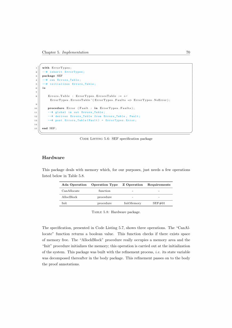
Chapter 5. Implementation 70
�1 with ErrorTypes ;
2 --# inherit ErrorTypes ;
3 package SEF
4 --# own Errors_Table ;
5 --# initializes Errors_Table ;
6 i s
7
8 Errors Table : ErrorTypes . ErrorsTable := ←↩
ErrorTypes . ErrorsTable ’ ( ErrorTypes . Faults => ErrorTypes . NoError ) ;
9
10 procedure Error ( Fault : in ErrorTypes . Faults ) ;
11 --# global in out Errors_Table ;
12 --# derives Errors_Table from Errors_Table , Fault ;
13 --# post Errors_Table ( Fault ) = ErrorTypes . Error ;
14
15 end SEF ;� Code Listing 5.6: SEF specification package
Hardware
This package deals with memory which, for our purposes, just needs a few operations
listed below in Table 5.8.
Ada Operation Operation Type Z Operation Requirements
CanAllocate function - -
AllocBlock procedure - -
Init procedure InitMemory SEF#01
Table 5.8: Hardware package.
The specification, presented in Code Listing 5.7, shows three operations. The “CanAl-
locate” function returns a boolean value. This function checks if there exists space
of memory free. The “AllockBlock” procedure really occupies a memory area and the
“Init” procedure initializes the memory; this operation is carried out at the initialization
of the system. This package was built with the refinement process, i.e. its state variable
was decomposed thereafter in the body package. This refinement passes on to the body
the proof annotations.
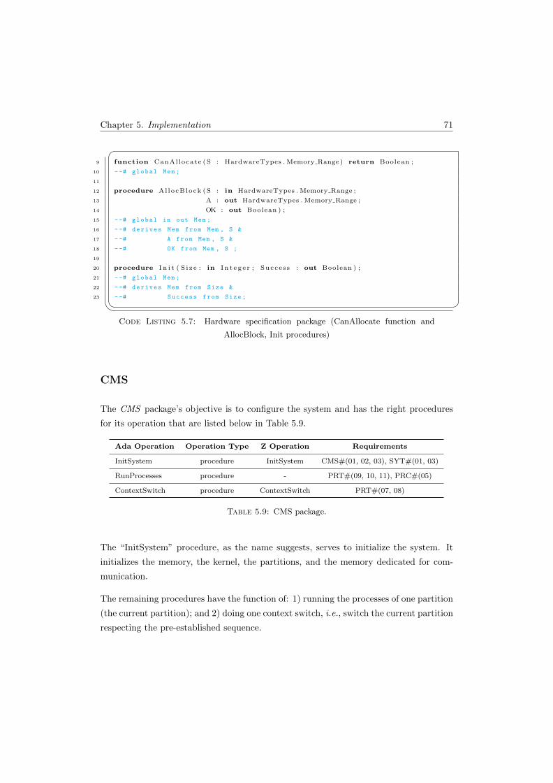
Chapter 5. Implementation 71
�9 function CanAllocate (S : HardwareTypes . Memory Range ) return Boolean ;
10 --# global Mem ;
11
12 procedure AllocBlock (S : in HardwareTypes . Memory Range ;
13 A : out HardwareTypes . Memory Range ;
14 OK : out Boolean ) ;
15 --# global in out Mem ;
16 --# derives Mem from Mem , S &
17 --# A from Mem , S &
18 --# OK from Mem , S ;
19
20 procedure I n i t ( S i z e : in I n t eg e r ; Success : out Boolean ) ;
21 --# global Mem ;
22 --# derives Mem from Size &
23 --# Success from Size ;� Code Listing 5.7: Hardware specification package (CanAllocate function and
AllocBlock, Init procedures)
CMS
The CMS package’s objective is to configure the system and has the right procedures
for its operation that are listed below in Table 5.9.
Ada Operation Operation Type Z Operation Requirements
InitSystem procedure InitSystem CMS#(01, 02, 03), SYT#(01, 03)
RunProcesses procedure - PRT#(09, 10, 11), PRC#(05)
ContextSwitch procedure ContextSwitch PRT#(07, 08)
Table 5.9: CMS package.
The “InitSystem” procedure, as the name suggests, serves to initialize the system. It
initializes the memory, the kernel, the partitions, and the memory dedicated for com-
munication.
The remaining procedures have the function of: 1) running the processes of one partition
(the current partition); and 2) doing one context switch, i.e., switch the current partition
respecting the pre-established sequence.

Chapter 5. Implementation 72
SYT
This package contains the system tables. It contains procedures for the initialization
of their tables (partitions, communications and PIFP), and provides the facilities for
managing these tables. The operations are summarized in Table 5.10.
Ada Operation Operation Type Z Operation Requirements
InitPartitionsTable procedure Init CMS#02, SYT#03
InitCommunicationsTable procedure InitComunications CMS#03, SYT#03
InitPIFPTable procedure InitPIFP CMS#03, SYT#03
GetPartitionIndex function - -
UpdateCommunicationList procedure UpdateComTablePRC#(01, 02, 03),
PIFP#06
Communication procedure Send, Receive PRC#04, PIFP#04
DeleteComForPartition procedure - PRC#(01, 02, 03)
ReadWrite procedure ReadWrite -
CheckPIFP procedure CheckPIFP PIFP#(02, 03, 05)
ChangePartitionMode procedurePartitionResumes,PartitionSuspends,CurrPartitionError
PRT#03
GetDurationPRT function GetDuration PRT#03
Table 5.10: SYT package.
The operations of initialization are used at the system boot time in the “InitSystem”
procedure from CSM package. The “InitPartitionsTable” procedure ensures that par-
titions are not created with shared memory spaces; the “InitCommunicationsTable”
procedure ensures that the blocks of memory for communication do not belong to any
of the partitions.
The other operations are used in the normal system operating. The “UpdateCommu-
nicationList” procedure is used by the processes with the aim to communicate with
the processes in other partitions, the remaining operations are used by the kernel in
the “ContextSwitch” procedure enabling or not the communications according to the
partition information flow policy chosen for the system.
Each partition can only access its memory and the communication memory that respects
the PIFP, they can not access the kernel memory or the other partitions memory, nor
the communication memory that belongs to them. In the communication memory each
Chapter 5. Implementation 73
partition has access to the free blocks; the access to the occupied blocks is only possible
when the target partition is the partition itself.
ConfigValues
This package is used to read the configuration file during the system booting. It contains
local states which are used only in the startup of the system. The package is necessary
to comply with the SYT#03 (the initial state of the system should be a secure state)
requirement. This package is extremely important because it verifies the integrity of the
configuration file, checks whether the format is well defined, if there is enough memory
to boot the system, and if there is a PIFP for all the partitions.
File
This package provides file utilities. It is distributed by praxis in the Tokeneer project
[8].
5.6 Other issues
The configuration file
The configuration data is supplied in a file named config.dat. The format of a configura-
tion data file is presented in Table 5.11. Each field is presented in a new line and takes
the form of a field identifier followed by at least one space and the value of the field.
Each line is terminated by a CR (carriage return) and LF (line feed). The file format
has been selected to provide a user-friendly interface for entering values.
An example of a valid configuration file is presented in Appendix D.
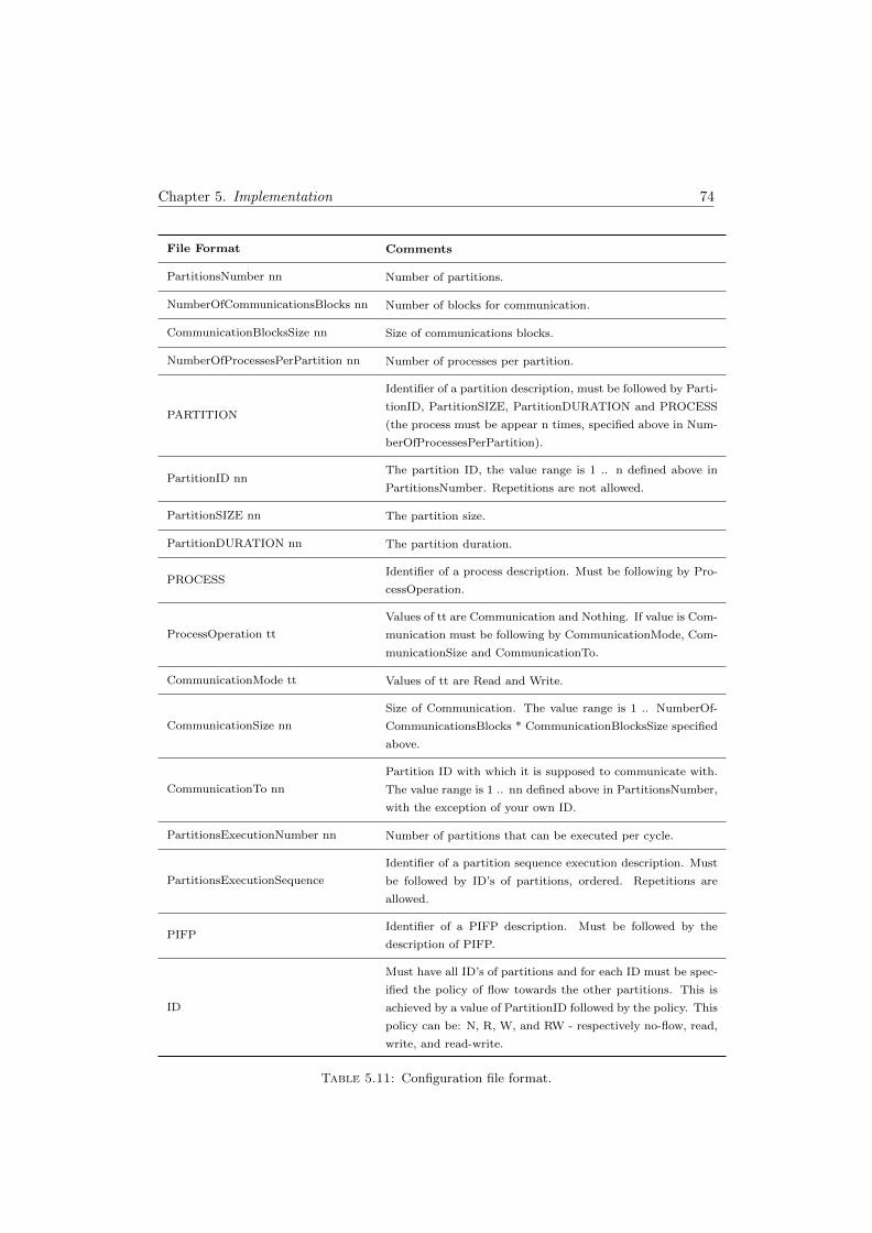
Chapter 5. Implementation 74
File Format Comments
PartitionsNumber nn Number of partitions.
NumberOfCommunicationsBlocks nn Number of blocks for communication.
CommunicationBlocksSize nn Size of communications blocks.
NumberOfProcessesPerPartition nn Number of processes per partition.
PARTITION
Identifier of a partition description, must be followed by Parti-
tionID, PartitionSIZE, PartitionDURATION and PROCESS
(the process must be appear n times, specified above in Num-
berOfProcessesPerPartition).
PartitionID nnThe partition ID, the value range is 1 .. n defined above in
PartitionsNumber. Repetitions are not allowed.
PartitionSIZE nn The partition size.
PartitionDURATION nn The partition duration.
PROCESSIdentifier of a process description. Must be following by Pro-
cessOperation.
ProcessOperation tt
Values of tt are Communication and Nothing. If value is Com-
munication must be following by CommunicationMode, Com-
municationSize and CommunicationTo.
CommunicationMode tt Values of tt are Read and Write.
CommunicationSize nn
Size of Communication. The value range is 1 .. NumberOf-
CommunicationsBlocks * CommunicationBlocksSize specified
above.
CommunicationTo nn
Partition ID with which it is supposed to communicate with.
The value range is 1 .. nn defined above in PartitionsNumber,
with the exception of your own ID.
PartitionsExecutionNumber nn Number of partitions that can be executed per cycle.
PartitionsExecutionSequence
Identifier of a partition sequence execution description. Must
be followed by ID’s of partitions, ordered. Repetitions are
allowed.
PIFPIdentifier of a PIFP description. Must be followed by the
description of PIFP.
ID
Must have all ID’s of partitions and for each ID must be spec-
ified the policy of flow towards the other partitions. This is
achieved by a value of PartitionID followed by the policy. This
policy can be: N, R, W, and RW - respectively no-flow, read,
write, and read-write.
Table 5.11: Configuration file format.
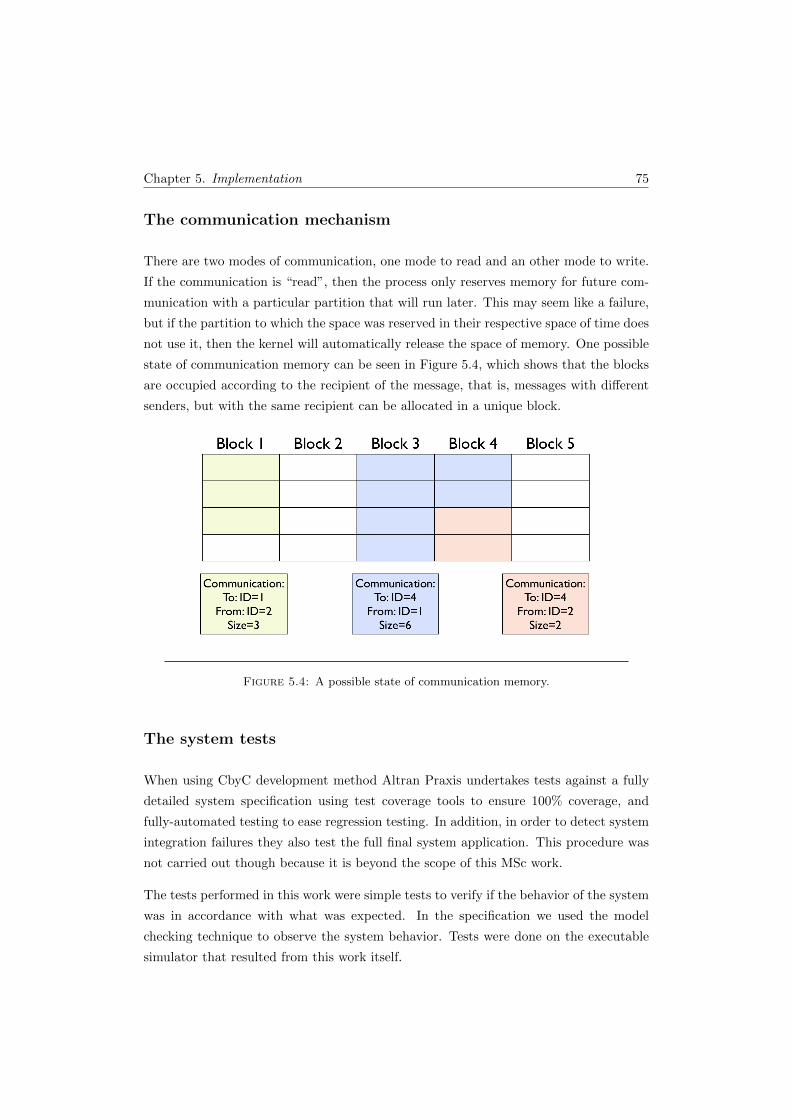
Chapter 5. Implementation 75
The communication mechanism
There are two modes of communication, one mode to read and an other mode to write.
If the communication is “read”, then the process only reserves memory for future com-
munication with a particular partition that will run later. This may seem like a failure,
but if the partition to which the space was reserved in their respective space of time does
not use it, then the kernel will automatically release the space of memory. One possible
state of communication memory can be seen in Figure 5.4, which shows that the blocks
are occupied according to the recipient of the message, that is, messages with different
senders, but with the same recipient can be allocated in a unique block.
Figure 5.4: A possible state of communication memory.
The system tests
When using CbyC development method Altran Praxis undertakes tests against a fully
detailed system specification using test coverage tools to ensure 100% coverage, and
fully-automated testing to ease regression testing. In addition, in order to detect system
integration failures they also test the full final system application. This procedure was
not carried out though because it is beyond the scope of this MSc work.
The tests performed in this work were simple tests to verify if the behavior of the system
was in accordance with what was expected. In the specification we used the model
checking technique to observe the system behavior. Tests were done on the executable
simulator that resulted from this work itself.
Chapter 5. Implementation 76
For these tests, we created a Ada package that allowed the visualization of the system
state, i.e. allowed us to compare the system behavior and the state of the variable
packages (packages with state) with the expected result. The Ada package created
allowed us to see the state of the following variable packages: SYT.Partitions Table,
SYT.Communications Table, SYT.PIFP Table, SYT.PartitionsExecutionSequence Table,
SEF.Errors Table, and Hardware.Mem.
Tests performed consisted of checking if it was the correct behavior, in accordance with
the selected configuration file (config.dat), by viewing the state of the system. Various
configuration files were created to test several possible scenarios. The different scenarios
that were tested can be separated into two groups:
• initialization: that tests the correct start of the system, such as the memory al-
location, the creation of partitions and processes, and the load of static tables
(PIFP Table and PartitionsExecutionSequence Table);
• execution: that tests the normal behavior of the system, like the memory access
control, the partitions exchange, the processes execution within a given partition,
and the communications between partitions matching the established PIFP.
Overall, any tests that may be undertaken complement the static analysis of the system
in order to confirm its dynamic behavior.
Results
The INFORMED stage is extremely useful because it allows us to have a mapping from
the formal design to the code prior to writing the code.
The static analysis can start with only the specification packages. This lets us know if
we adhere to the constraints of the SPARK language. With the specifications concluded,
we move on to the development of the bodies and consequently the implementation of
operations. With the facilities of the tools for SPARK we examine and verify the code
as we go. The operations can be analyzed with the SPARK Examiner to verify the data
and information flow properties of the code against the annotations in the specification.
Thus, we obtain the check of code before it is compiled.
When the code of the packages is complete, the SPARK Examiner provides a check for
run-time errors. This allows us to make sure that the code is free of errors that can cause

Chapter 5. Implementation 77
a run-time exception, such as accessing arrays outside their bounds or the overflow of
numeric types.
SPARK Examiner generates a number of VCs (Verification Conditions) for each sub-
program which needs to be shown true to conclude the proof of the subprogram. With
the POGS we always have an overview of the validation of the project. When there
are VCs that could not be discharged automatically, we can consult the file .siv of the
subprogram and see the problem. With this method it was possible to find some basic
flaws that had remained undetected. Figure 5.5 is an extract of the final result of POGS
and, as we can see, the Examiner and the Simplifier were able to prove all VCs in a fully
automatic way.
Figure 5.5: POGS summary.
Chapter 6
Conclusions
This chapter concludes the work described in this dissertation. An overview of the main
purpose of this study and its value to the scientific community is made. It is presented a
comparison of the results achieved with the initial objectives proposed; some limitations
that occurred during the work development also are pointed out. Finally, we present
some recommendations for future work, both regarding possible extensions/improve-
ments in the scope of this work or referring to new works with a similar development
methodology.
6.1 Main aim and objectives
We can say that the main aim initially indicated, the use of CbyC development method
to build a secure partitioning microkernel-based simulator, in order to confirm that it is
indeed possible to develop systems able to achieve high levels of certification, was overall
achieved.
As explained above, in Chapter 3, we outlined five objectives in order to achieve the
main aim. The work undertaken and the results obtained in each step are summarized
below.
1. To investigate the system requirements: this was indeed an essential step of
the work. It enabled the collection of the necessary information in order to move
78
Chapter 6. Conclusions 79
forward towards the system implementation goal. The documents SKPP [72] and
ARINC-653 [137] were used as reference;
2. To use the Z notation to create a high level specification: this step was
important for a full understanding of the features and properties of the system.
It enabled the creation of one specification (formal model), with the requirements
achieved in the previous step, in an unambiguous manner. In order to help the
understanding of the features and properties of the system, we used an animator
(ProZ) to obtain a more visual and interactive perspective of the specification.
The resulting model is simple but very representative of the system core;
3. To construct a design of the system with INFORMED process: with the
completion of this step, we produced an architecture that respects the specification
created above. Although the formal specification has been started first, the final
versions of the two stages were completed simultaneously. It allowed us, based on
the information contained in the formal specification to develop an architecture,
that besides helping in the elimination of unnecessary exchange of information,
it also serves as a complementary component that facilitates the passage of the
formal model for the packages used in the implementation of the system;
4. To implement the system in SPARK: the purpose of this step is to make the
various packages of the system. It is divided into two stages: first, the specification
creation; secondly, the bodies. The package specifications were created with the
assistance of the formal model and the resulting architecture from the INFORMED
design. These specifications include the Ada signature of the operations and the
respective SPARK annotations. With this, we carried out a basic check - between
the code and the annotations - to the information flow of operations. After the
completion of the specification packages, their respective implementations (the
body packages) were created. In the implementation, annotations that allowed the
following checks were inserted: data flow analysis, information flow analysis, and
proof of the absence of run-time errors. The properties of the formal specification
were included in the implementation as SPARK proof annotations;
5. To verify the system (using the SPARK Examiner toolset): the SPARK
Examiner tool was used over the resulting implementation from the previous step,
in order to perform the verification that the properties described in the specifica-
tions were matched in the code. Thus, we have the possibility to make an early
checking of the code (before compilation), so that we can prevent the introduction
of some common mistakes, for example the use of uninitialized variables. We can
Chapter 6. Conclusions 80
also check that we have no run-time errors, such as the access outside array or
the overflow of numeric types. The SPARK approach reduces the need for testing,
replacing it with analysis. The SPARK Examiner and SPADE Simplifier tools
were used on the implementation source code, in order to discharge the associ-
ated proof obligations (Verification Conditions (VCs) generated). The VCs who
have not been automatically proved were inspected, thereby finding some errors
that may would have been unnoticed; also, some annotations were remade so that
so they can be discharged automatically. In this way, we can reduce the num-
ber of VCs not discharged. However, some VCs were not automatically proved,
these could/should be further analyzed and proved, by hand or with the aid of a
semi-automatic prover, such as the Proof Checker tool.
The work reported in this dissertation addresses two subjects of great importance, as
the Formal Methods and the Operating Systems. The first one is important to assure
that a piece of software is well designed and implemented, and the second is also very
important because is the core of any system - the services that run on it depend directly
on its reliability. It is therefore inevitable, or at least it would be desirable, especially
when it comes to critical systems, that the construction of OS were carried out with the
use of formal methods. The work presented here, aims to highlight some aspects of this
combination in order to contribute to a better understanding of the needs and benefits
that may result from its use. This type of works, usually count on the association of
a large team with high technical skills and many years of experience in both areas. It
is clear enough that both of the subjects covered in this work have a high complexity;
the case study (secure partitioning microkernel) that has very advanced OS concepts
and the verification of software that becomes more complex and elaborate as the system
size increases. It was assumed from the very beginning that the lack of experience
would impose an important component of learning in the two fields in order to achieve
the objective. However, despite the learning effort done, we are aware that a greater
knowledge in these two areas is required to fully achieve the goals. There are two points,
one in each area, that limited our work. In the FM area, we talk about the notion of
manual proof; in the OS field, we talk about the integration with hardware. To some
extent these aspects constituted a limitation, restricting the scope of our work. In spite
of the difficulties above, it is expected that the results obtained may provide a basis for
new approaches on the subject, enabling knowledge about the properties and structures
necessary for its development.
Chapter 6. Conclusions 81
Evaluating this work globally, it can be concluded that the various steps followed that
compose the CbyC development method represent an added value when we want to
build a system with high standards of reliability. As explained previously in Chapter
2, the fact that a software has been fully proved does not guarantee that it really does
what it is expected to do. It may ensure that what ever is carried out is done without
errors. However, the use of the CbyC development method allows one to visualize and
understand, throughout the several steps, the system behavior, thus minimizing the risk
above. Even if the software does not need to achieve high levels of certification, this
methodology is very good to minimize mistakes and ultimately enables to make better
software.
6.2 Contributions
The verification and certification of software is an area of enormous importance as it
aims to ensure that no problems arise in delicate areas, safeguarding the preservation
of human life and the environment that surrounds it. The subject under study is also
of great relevance since it is a microkernel-based approach, which is clearly the central
defining feature of an OS.
The final aim of this work was not only the system per se but also to better understand
the development process and to increase the confidence on it. This work was part of a
perspective to enable the increase of awareness and recognition that formal methods of
software development can be used in a practical context. It is essentially a platform for
knowledge transfer and use of advanced tools for software engineering in an important
area such as safety critical.
The methodology used was based in the CbyC development method, which has been ap-
plied successfully in several contexts by Altran Praxis. As Anthony Hall says, “Correct-
ness by Construction is a radical, effective and economical method of building software
with high integrity especially for security-critical and safety-critical applications”. This
methodology was used in the Tokeneer project that intended to demonstrate that it was
possible to develop systems up to the level of rigor required by the highest standards of
the Common Criteria.
Our motivation emerges from the same line of the Tokeneer project (with the differences
of context and inherent limitations), but with another subject of study. The chosen case
study was a secure partitioning microkernel, which is very important and absolutely
Chapter 6. Conclusions 82
necessary in some critical systems. As previously mentioned, there are a considerable
number of efforts towards the formalization and verification of kernels, nevertheless the
majority does not concern this particular type of microkernel with partition and security
properties. Only in the commercial field this kind of system exists with high levels of
certification.
The contribution of this case study is therefore essentially a help to convince the software
safety community that is really possible to develop secure systems in a rigorous way
without neglecting the costs. Even so, we are aware that our work has not reached yet
a state that complies to the level of rigor required by the standards of the highest levels
of certification, which are required when security systems are concerned. Nevertheless,
all the steps undertaken during our work and the fulfillment as match as possible of the
CbyC development method allows us to assure that our secure partitioning microkernel-
based simulator does indeed what it was meant to.
We can say that the use of the CbyC development method leads us to develop well built
systems with a high level of quality. We strongly believe that this work may serve as a
basis in the development of other new works in the regards to the verification field using
FM.
6.3 Future work
Some suggestions for future contributions to improve the final result have emerged
throughout this work. The main topics are presented below.
• to make a formal specification more complete, in order to encompass the whole
system, in which all the properties of the system are proved, with more concrete
elements for a direct mapping to implementation;
• to automate the passage of the properties of formal specification for the SPARK
proof annotations, ensuring that the properties contained in the specification are
rigorously passed on to the implementation;
• to add proof annotations to enable a full system coverage, and afterwards, if nec-
essary, to prove all verification conditions generated by the SPARK tools, with
the proof assistant or by hand, thereby ensuring that the implementation of the
system is error-free;

Bibliography 83
• to investigate the “concurrency part”1 of SPARK in order to add some concurrency
properties, like time, since this work only used the “sequential part” of SPARK ;
• to change some aspects in order to make the system more flexible, like removing
the restriction on the fixed number of processes per partition;
• to add functionality to the kernel, such as support for keyboard or external devices,
in order to make broader use of the system;
• the followed step-by-step development method lead us to some choices, like specific
methods used in the various steps, that can be replaced if considered more conve-
nient (for example, changing the formal specification language, if people involved
have more experience in another formal language).
As a final remark, it should be noted that, in order to help and guide in the choices and
restrictions required by the hardware in works with a strong low level component, it is
extremely useful that the team involved in it may count on members with high skills on
OS. This is in fact an important factor both to guarantee the correct implementation
in the hardware available, and to ensure thereafter a level of acceptable performance,
given the wide range of peculiarities that can affect this.
1The “concurrency part” of SPARK, also known as RavenSPARK, was based on the RavenscarProfile [138] that defines a subset of the tasking features of Ada (giving deterministic concurrency)providing the means to construct highly-reliable concurrent programs.
Bibliography
[1] J. Bowen, “Formal Methods in Safety-Critical Standards,” IEEE Computer,
vol. 27, pp. 168–177, 1994. (Cited on pages v and vii.)
[2] J. P. Bowen and M. G. Hinchey, “Ten Commandments of Formal Methods... Ten
Years Later,” IEEE Computer, vol. 39, no. 1, pp. 40–48, 2006. (Cited on pages v
and vii.)
[3] “Altran Praxis - SPARK.” Web Page. http://www.altran-praxis.com/spark.
aspx. accessed May-2011. (Cited on pages v, vii, 3, 11, and 19.)
[4] “Altran Praxis - Correctness by Construction approach.” Web Page. http://
www.altran-praxis.com/cbyc.aspx. accessed July-2011. (Cited on pages v, vii,
and 19.)
[5] J. Alves-foss, W. S. Harrison, P. Oman, and C. Taylor, “The MILS Architecture for
High-Assurance Embedded Systems,” International Journal of Embedded Systems,
vol. 2, pp. 239–247, 2006. (Cited on pages v and vii.)
[6] J. Barnes, R. Chapman, R. Johnson, J. Widmaier, D. Cooper, and B. Everett,
“Engineering the Tokeneer Enclave Protection Software,” in 1st IEEE Interna-
tional Symposium on Secure Software Engineering, Mar. 2006. (Cited on page 3.)
[7] K.-K. Lau and Z. Wang, “Verified component-based software in SPARK: experi-
mental results for a missile guidance system,” Ada Lett., vol. XXVII, pp. 51–58,
November 2007. (Cited on page 3.)
[8] “The Tokeneer Project.” Web Page. http://www.adacore.com/tokeneer. ac-
cessed December-2009. (Cited on pages 3 and 73.)
[9] J. Woodcock, P. G. Larsen, J. Bicarregui, and J. Fitzgerald, “Formal methods:
Practice and experience,” ACM Comput. Surv., vol. 41, pp. 19:1–19:36, October
2009. (Cited on page 6.)
84

Bibliography 85
[10] “Frama-C.” Web Page. http://frama-c.cea.fr. accessed November-2010.
(Cited on pages 7 and 11.)
[11] T. Ball and S. Rajamani, “The SLAM Toolkit,” in Computer Aided Verification
(G. Berry, H. Comon, and A. Finkel, eds.), vol. 2102 of Lecture Notes in Computer
Science, pp. 260–264, Springer Berlin / Heidelberg, 2001. (Cited on page 7.)
[12] “Formal Methods Links, by Mark Utting.” Web Page. http://www.cs.waikato.
ac.nz/~marku/formalmethods.html. accessed August-2010. (Cited on page 8.)
[13] P. Hofner and G. Struth, “Can Refinement be Automated?,” Electron. Notes
Theor. Comput. Sci., vol. 201, pp. 197–222, March 2008. (Cited on page 8.)
[14] J. M. Spivey, Understanding Z: a specification language and its formal semantics.
New York, NY, USA: Cambridge University Press, 1988. (Cited on page 8.)
[15] “Formal Methods Wiki.” Web Page. http://formalmethods.wikia.com. ac-
cessed May-2011. (Cited on page 8.)
[16] “Community Z Tools.” Web Page. http://czt.sourceforge.net. accessed
January-2010. (Cited on page 8.)
[17] “The fuzz type-checker for Z.” Web Page. http://spivey.oriel.ox.ac.uk/
mike/fuzz. accessed December-2009. (Cited on pages 8 and 55.)
[18] “The ProofPower.” Web Page. http://www.lemma-one.com/ProofPower. ac-
cessed January-2010. (Cited on page 8.)
[19] M. Leuschel and M. Butler, “ProB: A Model Checker for B,” in Formal Methods
Europe 2003 (A. Keijiro, S. Gnesi, and M. Dino, eds.), vol. 2805, pp. 855–874,
Springer-Verlag, LNCS, 2003. (Cited on pages 8, 9, and 55.)
[20] “The HOL-Z.” Web Page. http://www.brucker.ch/projects/hol-z. accessed
January-2010. (Cited on page 8.)
[21] J.-R. Abrial, The B-book: assigning programs to meanings. New York, NY, USA:
Cambridge University Press, 1996. (Cited on pages 8 and 45.)
[22] P. Behm, P. Benoit, A. Faivre, and J.-M. Meynadier, “Meteor: A successful ap-
plication of B in a large project,” in Proceedings of the Wold Congress on Formal
Methods in the Development of Computing Systems-Volume I - Volume I, FM ’99,
(London, UK), pp. 369–387, Springer-Verlag, 1999. (Cited on page 9.)
Bibliography 86
[23] F. Badeau and A. Amelot, “Using B as a High Level Programming Language
in an Industrial Project: Roissy VAL,” in ZB 2005: Formal Specification and
Development in Z and B (H. Treharne, S. King, M. Henson, and S. Schneider,
eds.), vol. 3455, Springer Berlin / Heidelberg, 2005. (Cited on page 9.)
[24] K. Robinson, “The B method and the B toolkit,” in Algebraic Methodology and
Software Technology (M. Johnson, ed.), vol. 1349 of Lecture Notes in Computer
Science, pp. 576–580, Springer Berlin / Heidelberg, 1997. (Cited on page 9.)
[25] “Atelier B.” Web Page. http://www.atelierb.eu. accessed January-2010. (Cited
on page 9.)
[26] “Rodin.” Web Page. http://rodin.cs.ncl.ac.uk. accessed December-2010.
(Cited on page 9.)
[27] J.-R. Abrial, Modeling in Event-B: System and Software Engineering. New York,
NY, USA: Cambridge University Press, 1st ed., 2010. (Cited on page 9.)
[28] C. B. Jones, Software Development: A Rigorous Approach. Upper Saddle River,
NJ, USA: Prentice Hall PTR, 1980. (Cited on pages 9 and 45.)
[29] J. Fitzgerald and P. G. Larsen, Modelling Systems: Practical Tools and Techniques
in Software Development. New York, NY, USA: Cambridge University Press, 2009.
(Cited on page 9.)
[30] J. Fitzgerald, P. G. Larsen, P. Mukherjee, N. Plat, and M. Verhoef, Validated
Designs For Object-oriented Systems. Santa Clara, CA, USA: Springer-Verlag
TELOS, 2005. (Cited on page 9.)
[31] “VDMTools.” Web Page. http://www.vdmtools.jp/en. accessed May-2011.
(Cited on page 9.)
[32] “Overture tool project.” Web Page. http://www.overturetool.org. accessed
May-2011. (Cited on page 9.)
[33] S. Agerholm and P. G. Larsen, “A Lightweight Approach to Formal Methods,” in
Proceedings of the International Workshop on Current Trends in Applied Formal
Method: Applied Formal Methods, FM-Trends 98, (London, UK), pp. 168–183,
Springer-Verlag, 1999. (Cited on page 10.)
[34] S. Easterbrook, R. Lutz, R. Covington, J. Kelly, Y. Ampo, and D. Hamilton,
“Experiences Using Lightweight Formal Methods for Requirements Modeling,”
IEEE Trans. Softw. Eng., vol. 24, pp. 4–14, January 1998. (Not cited.)
Bibliography 87
[35] R. F. Paige and J. S. Ostroff, “Specification-Driven Design with Eiffel and Agents
for Teaching Lightweight Formal Methods,” in TFM, pp. 107–123, 2004. (Not
cited.)
[36] J. Bryans, J. Fitzgerald, A. Romanovsky, and A. Roth, “Formal Modelling and
Analysis of Business Information Applications with Fault Tolerant Middleware,”
in Proceedings of the 2009 14th IEEE International Conference on Engineering of
Complex Computer Systems, ICECCS ’09, (Washington, DC, USA), pp. 68–77,
IEEE Computer Society, 2009. (Cited on page 10.)
[37] D. Jackson, Software Abstractions: Logic, Language, and Analysis. The MIT
Press, 2006. (Cited on page 10.)
[38] G. Holzmann, SPIN Model Checker, The: Primer and Reference Manual. Addison-
Wesley Professional, 2003. (Cited on pages 10 and 44.)
[39] J. Bengtsson, K. G. Larsen, F. Larsson, P. Pettersson, and W. Yi, “Uppaal
— a Tool Suite for Automatic Verification of Real–Time Systems,” in Proc. of
Workshop on Verification and Control of Hybrid Systems III, no. 1066 in Lecture
Notes in Computer Science, pp. 232–243, Springer–Verlag, Oct. 1995. (Cited on
page 10.)
[40] Y. Yu, P. Manolios, and L. Lamport, “Model Checking TLA+ Specifications,” in
CHARME, pp. 54–66, 1999. (Cited on page 11.)
[41] L. Lamport, Specifying Systems: The TLA+ Language and Tools for Hardware
and Software Engineers. Addison-Wesley Longman Publishing Co., Inc., 1st ed.,
July 2002. (Cited on page 11.)
[42] L. Lamport, “The Temporal Logic of Actions,” ACM Trans. Program. Lang. Syst.,
vol. 16, no. 3, pp. 872–923, 1994. (Cited on page 11.)
[43] “TLA+ toolbox.” Web Page. http://www.tlaplus.net/tools/tla-toolbox. ac-
cessed May-2011. (Cited on page 11.)
[44] C. A. R. Hoare, “An axiomatic basis for computer programming,” Commun. ACM,
vol. 12, pp. 576–580, October 1969. (Cited on page 11.)
[45] B. Meyer, “Applying ”Design by Contract”,” IEEE Computer, vol. 25, no. 10,
pp. 40–51, 1992. (Cited on page 11.)
[46] B. Meyer, Eiffel: the language. Upper Saddle River, NJ, USA: Prentice-Hall, Inc.,
1992. (Cited on page 11.)
Bibliography 88
[47] B. Meyer, “Eiffel: a language and environment for software engineering,” J. Syst.
Softw., vol. 8, no. 3, pp. 199–246, 1988. (Cited on page 11.)
[48] “Spec Sharp.” Web Page. http://research.microsoft.com/en-us/projects/
specsharp. accessed November-2010. (Cited on page 11.)
[49] P. Baudin, J.-C. Filliatre, C. Marche, B. Monate, Y. Moy, and V. Prevosto, ACSL:
ANSI/ISO C Specification Language, version 1.4, 2009. http://frama-c.cea.
fr/acsl.html. (Cited on page 11.)
[50] “Java Modeling Language.” Web Page. http://www.eecs.ucf.edu/~leavens/
JML. accessed November-2010. (Cited on page 11.)
[51] “ESC/Java2.” Web Page. http://kind.ucd.ie/products/opensource/
ESCJava2. accessed November-2010. (Cited on page 11.)
[52] R. Helm, I. M. Holland, and D. Gangopadhyay, “Contracts: specifying behavioral
compositions in object-oriented systems,” in OOPSLA/ECOOP ’90: Proceedings
of the European conference on object-oriented programming on Object-oriented pro-
gramming systems, languages, and applications, (New York, NY, USA), pp. 169–
180, ACM, 1990. (Cited on page 11.)
[53] J. Barnes, High Integrity Software: The SPARK Approach to Safety and Security.
Boston, MA, USA: Addison-Wesley Longman Publishing Co., Inc., 2003. (Cited
on pages 12, 14, 19, and 26.)
[54] J. M. Spivey, The Z notation: a reference manual. Hertfordshire, UK, UK: Prentice
Hall International (UK) Ltd., 1992. (Cited on page 22.)
[55] Altran Praxis, “Tool Development and Support - INFORMED Design Method for
SPARK,” 2010. (Cited on pages 24 and 25.)
[56] Altran Praxis, “SPARK Examiner - User Manual,” 2010. (Cited on page 26.)
[57] Altran Praxis, “SPARK Simplifier - User Manual,” 2010. (Cited on page 27.)
[58] Altran Praxis, “SPADE Proof Checker - User Manual,” 2010. (Cited on page 27.)
[59] Altran Praxis, “POGS - POGS User Manual,” 2010. (Cited on page 27.)
[60] J. P. Anderson, “Computer Security technology planning study,” tech. rep.,
Deputy for Command and Management System, USA, 1972. (Cited on page 29.)
Bibliography 89
[61] “Common Criteria for Information Technology Security Evaluation.” Web Page.
http://www.commoncriteriaportal.org. accessed May-2010. (Cited on
page 30.)
[62] J. Liedtke, “On µ-kernel construction,” in SOSP ’95: Proceedings of the fifteenth
ACM symposium on Operating systems principles, (New York, NY, USA), pp. 237–
250, ACM, 1995. (Cited on pages 31 and 47.)
[63] P. B. Hansen, “The nucleus of a multiprogramming system,” Commun. ACM,
vol. 13, no. 4, pp. 238–241, 1970. (Cited on page 31.)
[64] R. Rashid, R. Baron, R. Forin, D. Golub, and M. Jones, “Mach: A system software
kernel,” in Proceedings of the 1989 IEEE International Conference, COMPCON,
pp. 176–178, Press, 1989. (Cited on pages 31 and 43.)
[65] J. M. Rushby, “Design and verification of secure systems,” SIGOPS Oper. Syst.
Rev., vol. 15, no. 5, pp. 12–21, 1981. (Cited on pages 32 and 49.)
[66] J. Rushby and B. Randell, “A Distributed Secure System,” IEEE Computer,
vol. 16, pp. 55–67, July 1983. (Cited on page 35.)
[67] B. Randell and J. Rushby, “Distributed Secure Systems: Then and Now,” in Pro-
ceedings of the Twenty-Third Annual Computer Security Applications Conference,
(Miami Beach, FL), pp. 177–198, IEEE Computer Society, Dec. 2007. Invited
“Classic Paper” presentation. (Cited on page 35.)
[68] R. T. C. for Aeronautics (RTCA) Inc., DO-178B: Software Considerations in Air-
borne Systems and Equipment Certification. Radio Technical Commission for Aero-
nautics (RTCA), 1992. (Cited on page 35.)
[69] “The Boeing Company.” Web Page. http://www.boeing.com. accessed June-
2011. (Cited on page 36.)
[70] “Real-Time Innovations.” Web Page. http://www.rti.com. accessed June-2011.
(Cited on page 36.)
[71] “Wind River.” Web Page. http://www.windriver.com. accessed June-2011.
(Cited on page 36.)
[72] “Validated Protection Profile - U.S. Government Protection Profile for Separation
Kernels in Environments Requiring High Robustness, Version 1.03,” 2007. (Cited
on pages 37, 79, and 97.)
Bibliography 90
[73] “Green Hills, Aerospace and Defense.” Web Page. http://www.ghs.com/
AerospaceDefense.html. accessed December-2009. (Cited on page 38.)
[74] “Green Hills, INTEGRITY-178B.” Web Page. http://www.ghs.com/security/
security_home.html. accessed December-2009. (Cited on page 38.)
[75] “LinuxWorks.” Web Page. http://www.lynuxworks.com. accessed May-2010.
(Cited on page 38.)
[76] “SYSGO Embedding Innovations.” Web Page. http://www.sysgo.com. accessed
May-2010. (Cited on page 38.)
[77] G. Klein, “Operating System Verification — An Overview,” Sadhana, vol. 34,
pp. 27–69, Feb. 2009. (Cited on pages 41 and 49.)
[78] P. Neumann, R. Boyer, R. Feiertag, K. Levitt, and L. Robinson, “A provably secure
operating system: The system, its applications, and proofs, second edition, report
csl-116,” tech. rep., Computer Science Laboratory, SRI International, Menlo Park,
CA, USA, 1980. (Cited on page 41.)
[79] B. J. Walker, R. A. Kemmerer, and G. J. Popek, “Specification and verification
of the UCLA Unix security kernel,” Commun. ACM, vol. 23, no. 2, pp. 118–131,
1980. (Cited on pages 41 and 42.)
[80] W. R. Bevier, A verified operating system kernel. PhD thesis, The University
of Texas at Austin, 1987. Supervisor-Boyer, Robert S. and Supervisor-Moore, J.
Strother. (Cited on pages 41 and 43.)
[81] L. Robinson and K. N. Levitt, “Proof techniques for hierarchically structured
programs,” Commun. ACM, vol. 20, no. 4, pp. 271–283, 1977. (Cited on page 41.)
[82] P. G. Neumann and R. J. Feiertag, “PSOS Revisited,” in ACSAC ’03: Proceedings
of the 19th Annual Computer Security Applications Conference, (Washington, DC,
USA), p. 208, IEEE Computer Society, 2003. (Cited on page 42.)
[83] T. A. Berson and J. G. L. Barksdale, “KSOS - Development methodology for a se-
cure operating system,” Managing Requirements Knowledge, International Work-
shop on, vol. 0, p. 365, 1979. (Cited on page 42.)
[84] E. J. McCauley and P. J. Brongowski, “KSOS - The design of a secure operating
system,” Managing Requirements Knowledge, International Workshop on, vol. 0,
p. 345, 1979. (Cited on page 42.)
Bibliography 91
[85] W. Boebert, R. Kaln, W. Young, and S. Hansohn, “Secure Ada Target: Issues,
System Design, and Verification,” Security and Privacy, IEEE Symposium on,
vol. 0, p. 176, 1985. (Cited on page 42.)
[86] M. Gargano, M. Hillebrand, D. Leinenbach, and W. Paul, “On the Correctness of
Operating System Kernels,” Theorem Proving in Higher Order Logics, pp. 1–16,
2005. (Cited on page 42.)
[87] T. In der Rieden and A. Tsyban, “CVM – A Verified Framework for Microkernel
Programmers,” Electron. Notes Theor. Comput. Sci., vol. 217, pp. 151–168, 2008.
(Cited on page 42.)
[88] J. Dorrenbacher, Formal Specification and Verification of a Microkernel. PhD
thesis, Saarland University, November 2010. (Cited on page 42.)
[89] M. Daum, On the Formal Foundation of a Verification Approach for System-Level
Concurrent Programs. PhD thesis, Saarland University, Aug. 2010. (Cited on
page 42.)
[90] W. R. Bevier, “Kit: A Study in Operating System Verification,” IEEE Trans.
Softw. Eng., vol. 15, no. 11, pp. 1382–1396, 1989. (Cited on page 43.)
[91] R. Boyer and J. Moore, A Computational Logic. ACM monograph series, Academic
Press, 1979. (Cited on page 43.)
[92] M. Kaufmann, J. S. Moore, and P. Manolios, Computer-Aided Reasoning: An
Approach. Norwell, MA, USA: Kluwer Academic Publishers, 2000. (Cited on
page 43.)
[93] W. R. Bevier and L. M. Smith, “A Mathematical Model of the Mach Kernel,”
tech. rep., High Level Architectural Design, Technical Report 103, Computational
Logic, Inc, 1994. (Cited on page 43.)
[94] R. L. Ford, R. T. Simon, W. R. Bevier, and L. M. Smith, “The Specification-
Based Testing of a Trusted Kernel: MK++,” in ICFEM ’97: Proceedings of the
1st International Conference on Formal Engineering Methods, (Washington, DC,
USA), p. 151, IEEE Computer Society, 1997. (Cited on page 43.)
[95] T. open Group, “MK++ Kernel Executive Summary,” tech. rep., Open Software
Foundation Research Institute, 1995. (Cited on page 43.)
[96] G. Duval and J. Julliand, “Modeling and Verification of the RUBIS µ-Kernel with
SPIN,” in Proceedings of the First SPIN Workshop, 1995. (Cited on page 44.)
Bibliography 92
[97] J. M. Faria, “Formal Development of Solutions for Real-Time Operating System
with TLA+/TLC,” Master’s thesis, Universidade do Porto, Portugal, 2008. (Cited
on page 44.)
[98] M. Archer, E. Leonard, and M. Pradella, “Analyzing security-enhanced Linux
policy specifications,” in POLICY ’03: Proceedings of the 4th IEEE International
Workshop on Policies for Distributed Systems and Networks, (Washington, DC,
USA), p. 158, IEEE Computer Society, 2003. (Cited on page 44.)
[99] R. Spencer, S. Smalley, P. Loscocco, M. Hibler, D. Andersen, and J. Lepreau,
“The Flask Security Architecture: System Support for Diverse Security Policies,”
in SSYM’99: Proceedings of the 8th conference on USENIX Security Symposium,
(Berkeley, CA, USA), pp. 11–11, USENIX Association, 1999. (Cited on page 44.)
[100] B. Ford, M. Hibler, J. Lepreau, P. Tullmann, G. Back, and S. Clawson, “Micro-
kernels meet recursive virtual machines,” in OSDI ’96: Proceedings of the second
USENIX symposium on Operating systems design and implementation, (New York,
NY, USA), pp. 137–151, ACM, 1996. (Cited on page 44.)
[101] M. Archer, C. Heitmeyer, and E. Riccobene, “Using TAME to prove invariants
of automata models: Two case studies,” in FMSP ’00: Proceedings of the third
workshop on Formal methods in software practice, (New York, NY, USA), pp. 25–
36, ACM, 2000. (Cited on page 44.)
[102] N. Shankar, S. Owre, J. M. Rushby, and D. W. J. Stringer-Calvert, PVS Prover
Guide. Computer Science Laboratory, SRI International, Menlo Park, CA, Sept.
1999. (Cited on page 44.)
[103] J. D. Guttman, A. L. Herzog, J. D. Ramsdell, and C. W. Skorupka, “Verifying
information flow goals in security-enhanced Linux,” J. Comput. Secur., vol. 13,
no. 1, pp. 115–134, 2005. (Cited on page 44.)
[104] S. Fowler and A. J. Wellings, “Formal Analysis of a Real-Time Kernel Specifica-
tion,” in FTRTFT ’96: Proceedings of the 4th International Symposium on Formal
Techniques in Real-Time and Fault-Tolerant Systems, (London, UK), pp. 440–458,
Springer-Verlag, 1996. (Cited on page 45.)
[105] S. Fowler and A. Wellings, “Formal development of a real-time kernel,” in RTSS
’97: Proceedings of the 18th IEEE Real-Time Systems Symposium, (Washington,
DC, USA), p. 220, IEEE Computer Society, 1997. (Cited on page 45.)
Bibliography 93
[106] F. Jahanian and A. K. Mok, “Safety analysis of timing properties in real-time
systems,” IEEE Trans. Softw. Eng., vol. 12, pp. 890–904, September 1986. (Cited
on page 45.)
[107] M.-Y. Zhu, L. Luo, and G.-Z. Xiong, “A provably correct operating system: δ-
core,” SIGOPS Oper. Syst. Rev., vol. 35, no. 1, pp. 17–33, 2001. (Cited on page 45.)
[108] M. Y. Zhu and C. W. Wang, “A Higher-Order Lambda Calculus: PowerEpsilon,”
tech. rep., Beijing Institute of Systems Engineering, 1991. (Cited on page 45.)
[109] I. D. Craig, Formal Models of Operating System Kernels. Secaucus, NJ, USA:
Springer-Verlag New York, Inc., 2006. (Cited on pages 45, 51, and 57.)
[110] J. S. Shapiro and S. Weber, “Verifying Operating System Security,” tech. rep.,
University of Pennsylvania, Philadelphia, PA, USA, 1997. (Cited on page 46.)
[111] J. S. Shapiro, J. M. Smith, and D. J. Farber, “EROS: a fast capability system,” in
SOSP ’99: Proceedings of the seventeenth ACM symposium on Operating systems
principles, (New York, NY, USA), pp. 170–185, ACM, 1999. (Not cited.)
[112] J. S. Shapiro and S. Weber, “Verifying the EROS Confinement Mechanism,” in SP
’00: Proceedings of the 2000 IEEE Symposium on Security and Privacy, (Wash-
ington, DC, USA), p. 166, IEEE Computer Society, 2000. (Cited on page 46.)
[113] J. Shapiro, M. S. Doerrie, E. Northup, and M. Miller, “Towards a verified, general-
purpose operating system kernel,” in Proc. NICTA Formal Methods Workshop on
OS Verification, pp. 1–19, NICTA Technical Report 0401005T-1, National ICT
Australia, 2004. (Cited on page 46.)
[114] K. Elphinstone, G. Klein, P. Derrin, T. Roscoe, and G. Heiser, “Towards a prac-
tical, verified kernel,” in HOTOS’07: Proceedings of the 11th USENIX workshop
on Hot topics in operating systems, (Berkeley, CA, USA), pp. 1–6, USENIX Asso-
ciation, 2007. (Cited on page 47.)
[115] G. Klein, K. Elphinstone, G. Heiser, J. Andronick, D. Cock, P. Derrin, D. Elka-
duwe, K. Engelhardt, R. Kolanski, M. Norrish, T. Sewell, H. Tuch, and S. Win-
wood, “seL4: formal verification of an OS kernel,” in SOSP ’09: Proceedings of
the ACM SIGOPS 22nd symposium on Operating systems principles, (New York,
NY, USA), pp. 207–220, ACM, 2009. (Cited on page 47.)
Bibliography 94
[116] H. Tuch, G. Klein, and G. Heiser, “OS verification: now!,” in HOTOS’05: Pro-
ceedings of the 10th conference on Hot Topics in Operating Systems, (Berkeley,
CA, USA), pp. 7–12, USENIX Association, 2005. (Cited on page 47.)
[117] K. Elphinstone, “Future Directions in the Evolution of the L4 Microkernel,” in
Proc. NICTA Formal Methods Workshop on OS Verification, NICTA Technical
Report 0401005T-1, National ICT Australia, 2004. (Cited on page 47.)
[118] G. Klein and H. Tuch, “Towards Verified Virtual Memory in L4,” in TPHOLs
Emerging Trends ’04 (K. Slind, ed.), (Park City, Utah, USA), p. 16 pages, Sept.
2004. (Cited on page 47.)
[119] H. Tuch and G. Klein, “Verifying the L4 virtual memory subsystem,” in Proc.
NICTA Formal Methods Workshop on OS Verification (G. Klein, ed.), pp. 73–97,
NICTA Technical Report 0401005T-1, National ICT Australia, 2004. (Cited on
page 47.)
[120] R. Kolanski and G. Klein, “Formalising the L4 microkernel API,” in CATS ’06:
Proceedings of the 12th Computing: The Australasian Theroy Symposium, (Dar-
linghurst, Australia, Australia), pp. 53–68, Australian Computer Society, Inc.,
2006. (Cited on page 47.)
[121] M. Hohmuth, H. Tews, and S. G. Stephens, “Applying source-code verification to
a microkernel: the VFiasco project,” in EW 10: Proceedings of the 10th workshop
on ACM SIGOPS European workshop, (New York, NY, USA), pp. 165–169, ACM,
2002. (Cited on page 47.)
[122] H. Tews, “Formal Methods in the Robin project: Specification and verification of
the Nova Microhypervisor,” 2007. (Cited on page 48.)
[123] H. Tews, T. Weber, and M. Volp, “A Formal Model of Memory Peculiarities for
the Verification of Low-Level Operating-System Code,” Electron. Notes Theor.
Comput. Sci., vol. 217, pp. 79–96, 2008. (Cited on page 48.)
[124] J. Rushby, “Proof of Separability—A verification technique for a class of secu-
rity kernels,” in Proc. 5th International Symposium on Programming, vol. 137 of
Lecture Notes in Computer Science, (Turin, Italy), pp. 352–367, Springer-Verlag,
Apr. 1982. (Cited on page 49.)
[125] P. Ammann, “A Safety Kernel for Traffic Light Control,” in Proc. of the Tenth
Annual Conference on Computer Assurance, pp. 71–81, 1994. (Cited on page 49.)
Bibliography 95
[126] W. Martin, P. White, F. S. Taylor, and A. Goldberg, “Formal Construction of the
Mathematically Analyzed Separation Kernel,” in ASE ’00: Proceedings of the 15th
IEEE international conference on Automated software engineering, (Washington,
DC, USA), p. 133, IEEE Computer Society, 2000. (Cited on page 49.)
[127] W. B. Martin, P. D. White, and F. S. Taylor, “Creating High Confidence in a
Separation Kernel,” Automated Software Engg., vol. 9, no. 3, pp. 263–284, 2002.
(Cited on page 49.)
[128] Y. V. Srinivas, Y. V. Srinivas, R. Jullig, and R. Jullig, “Specware: Formal support
for composing software,” in Mathematics of Program Construction, pp. 399–422,
Springer-Verlag, 1995. (Cited on page 49.)
[129] L. Luo and M.-Y. Zhu, “Partitioning based operating system: a formal model,”
SIGOPS Oper. Syst. Rev., vol. 37, no. 3, pp. 23–35, 2003. (Cited on page 50.)
[130] D. Greve, R. Richards, and M. Wilding, “A summary of intrinsic partitioning
verification,” in Proceedings of the Fifth International Workshop on the ACL2
Theorem Prover and Its Applications (ACL2), 2004. (Cited on page 50.)
[131] D. G. Matthew, M. Wilding, and W. M. V. Eet, “A Separation Kernel Formal
Security Policy,” in Proc. Fourth International Workshop on the ACL2 Theorem
Prover and Its Applications, 2003. (Cited on page 50.)
[132] C. L. Heitmeyer, M. Archer, E. I. Leonard, and J. McLean, “Formal specifica-
tion and verification of data separation in a separation kernel for an embedded
system,” in CCS ’06: Proceedings of the 13th ACM conference on Computer and
communications security, (New York, NY, USA), pp. 346–355, ACM, 2006. (Cited
on page 50.)
[133] C. Heitmeyer, M. Archer, E. Leonard, and J. McLean, “Applying Formal Methods
to a Certifiably Secure Software System,” IEEE Trans. Softw. Eng., vol. 34, no. 1,
pp. 82–98, 2008. (Cited on page 50.)
[134] C. E. Landwehr, C. L. Heitmeyer, and J. McLean, “A security model for military
message systems,” ACM Trans. Comput. Syst., vol. 2, no. 3, pp. 198–222, 1984.
(Cited on page 50.)
[135] I. D. Craig, Formal Refinement for Operating System Kernels. Secaucus, NJ, USA:
Springer-Verlag New York, Inc., 2007. (Cited on pages 51 and 57.)
Bibliography 96
[136] A. B. Passos, “Towards a formally designed and verified embedded operating sys-
tem: case study using the B Method,” Master’s thesis, Universidade da Beira
Interior, Portugal, 2009. (Cited on page 51.)
[137] “ARINC 653-P1-2 Avionics Application Software Standard Interface, Part 1 -
Required Services,” 2006. (Cited on pages 79 and 97.)
[138] A. Burns, B. Dobbing, and T. Vardanega, “Guide for the use of the Ada Ravenscar
Profile in high integrity systems,” Ada Lett., vol. XXIV, no. 2, pp. 1–74, 2004.
(Cited on page 83.)
Appendix A
Requirements
The list of the requirements is presented in this appendix. The documents SKPP [72]
and ARINC-653 [137] were used as reference to this survey of requirements.
SKPP is a Common Criteria Protection Profile for separation kernels and ARINC-653
is a standard specification for system partitioning and scheduling, particularly in the
avionics industry.
Similarities between SKPP and ARINC-653 are quite obvious. Both are used in appli-
cations requiring a design for high robust environments. The main difference is in com-
munication. In SKKP communication between applications requires an authorization,
whereas in ARINC-653 is not required any permission. Both SKPP and ARINC-653
provide a definition of mechanism that tries to address the enabling of multiple appli-
cations to be executed. The difference in SKPP is that each application should execute
not only in a safe environment but also in a secure one.
Below are presented the functional requirements of the system. A functional requirement
is a type of requirement that specifies a function that a system or component must be
able to perform.
The Table A.1 show the format in which the system requirements are presented.
97
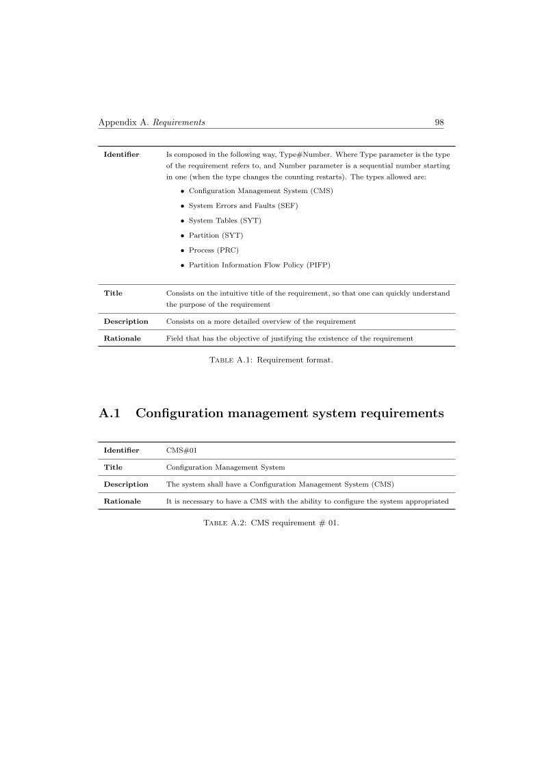
Appendix A. Requirements 98
Identifier Is composed in the following way, Type#Number. Where Type parameter is the type
of the requirement refers to, and Number parameter is a sequential number starting
in one (when the type changes the counting restarts). The types allowed are:
• Configuration Management System (CMS)
• System Errors and Faults (SEF)
• System Tables (SYT)
• Partition (SYT)
• Process (PRC)
• Partition Information Flow Policy (PIFP)
Title Consists on the intuitive title of the requirement, so that one can quickly understand
the purpose of the requirement
Description Consists on a more detailed overview of the requirement
Rationale Field that has the objective of justifying the existence of the requirement
Table A.1: Requirement format.
A.1 Configuration management system requirements
Identifier CMS#01
Title Configuration Management System
Description The system shall have a Configuration Management System (CMS)
Rationale It is necessary to have a CMS with the ability to configure the system appropriated
Table A.2: CMS requirement # 01.
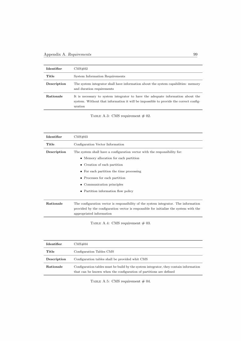
Appendix A. Requirements 99
Identifier CMS#02
Title System Information Requirements
Description The system integrator shall have information about the system capabilities: memory
and duration requirements
Rationale It is necessary to system integrator to have the adequate information about the
system. Without that information it will be impossible to provide the correct config-
uration
Table A.3: CMS requirement # 02.
Identifier CMS#03
Title Configuration Vector Information
Description The system shall have a configuration vector with the responsibility for:
• Memory allocation for each partition
• Creation of each partition
• For each partition the time processing
• Processes for each partition
• Communication principles
• Partition information flow policy
Rationale The configuration vector is responsibility of the system integrator. The information
provided by the configuration vector is responsible for initialize the system with the
appropriated information
Table A.4: CMS requirement # 03.
Identifier CMS#04
Title Configuration Tables CMS
Description Configuration tables shall be provided whit CMS
Rationale Configuration tables must be build by the system integrator, they contain information
that can be known when the configuration of partitions are defined
Table A.5: CMS requirement # 04.
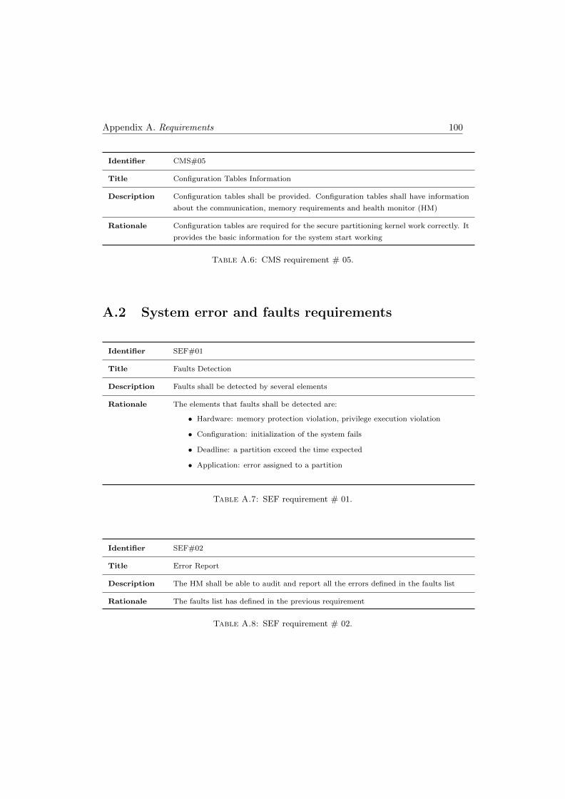
Appendix A. Requirements 100
Identifier CMS#05
Title Configuration Tables Information
Description Configuration tables shall be provided. Configuration tables shall have information
about the communication, memory requirements and health monitor (HM)
Rationale Configuration tables are required for the secure partitioning kernel work correctly. It
provides the basic information for the system start working
Table A.6: CMS requirement # 05.
A.2 System error and faults requirements
Identifier SEF#01
Title Faults Detection
Description Faults shall be detected by several elements
Rationale The elements that faults shall be detected are:
• Hardware: memory protection violation, privilege execution violation
• Configuration: initialization of the system fails
• Deadline: a partition exceed the time expected
• Application: error assigned to a partition
Table A.7: SEF requirement # 01.
Identifier SEF#02
Title Error Report
Description The HM shall be able to audit and report all the errors defined in the faults list
Rationale The faults list has defined in the previous requirement
Table A.8: SEF requirement # 02.
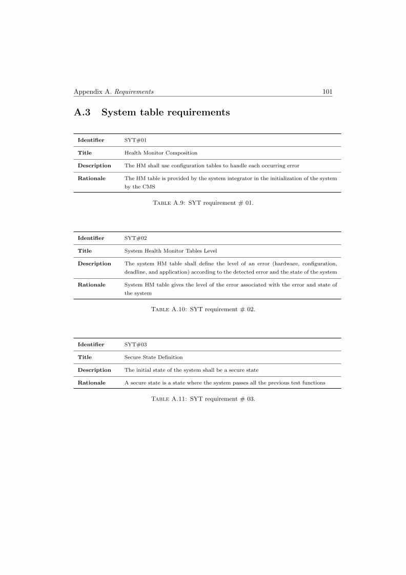
Appendix A. Requirements 101
A.3 System table requirements
Identifier SYT#01
Title Health Monitor Composition
Description The HM shall use configuration tables to handle each occurring error
Rationale The HM table is provided by the system integrator in the initialization of the system
by the CMS
Table A.9: SYT requirement # 01.
Identifier SYT#02
Title System Health Monitor Tables Level
Description The system HM table shall define the level of an error (hardware, configuration,
deadline, and application) according to the detected error and the state of the system
Rationale System HM table gives the level of the error associated with the error and state of
the system
Table A.10: SYT requirement # 02.
Identifier SYT#03
Title Secure State Definition
Description The initial state of the system shall be a secure state
Rationale A secure state is a state where the system passes all the previous test functions
Table A.11: SYT requirement # 03.
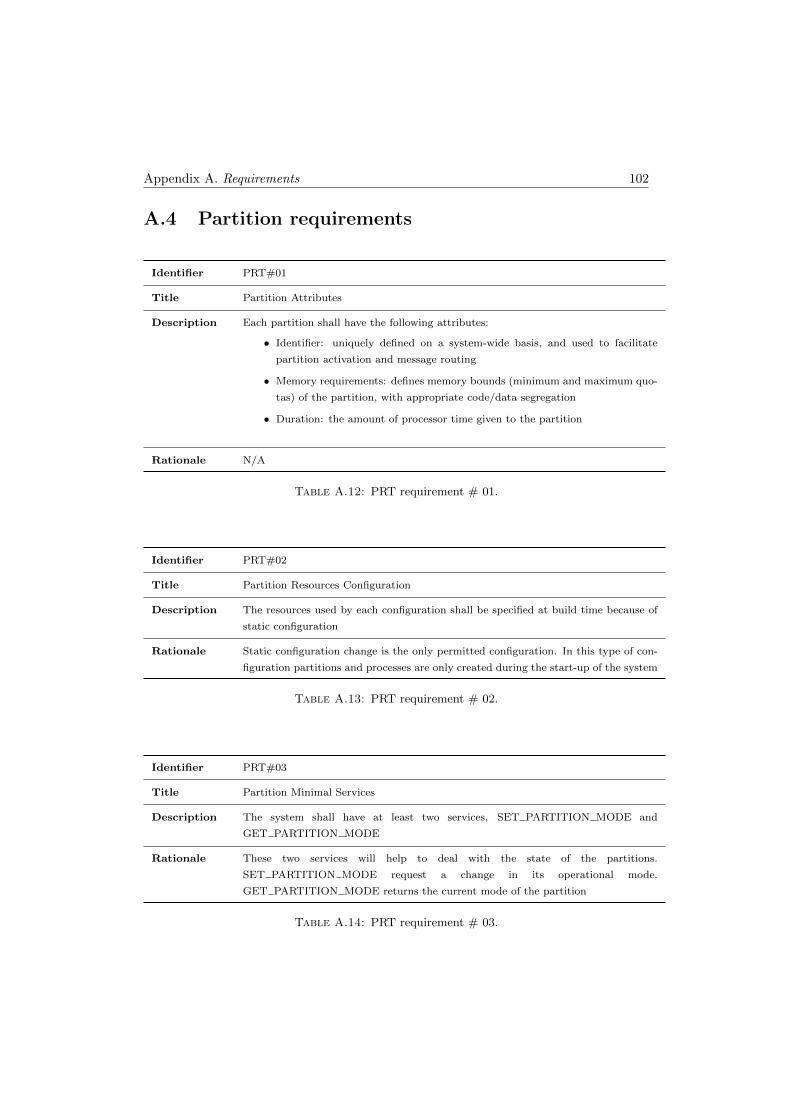
Appendix A. Requirements 102
A.4 Partition requirements
Identifier PRT#01
Title Partition Attributes
Description Each partition shall have the following attributes:
• Identifier: uniquely defined on a system-wide basis, and used to facilitate
partition activation and message routing
• Memory requirements: defines memory bounds (minimum and maximum quo-
tas) of the partition, with appropriate code/data segregation
• Duration: the amount of processor time given to the partition
Rationale N/A
Table A.12: PRT requirement # 01.
Identifier PRT#02
Title Partition Resources Configuration
Description The resources used by each configuration shall be specified at build time because of
static configuration
Rationale Static configuration change is the only permitted configuration. In this type of con-
figuration partitions and processes are only created during the start-up of the system
Table A.13: PRT requirement # 02.
Identifier PRT#03
Title Partition Minimal Services
Description The system shall have at least two services, SET PARTITION MODE and
GET PARTITION MODE
Rationale These two services will help to deal with the state of the partitions.
SET PARTITION MODE request a change in its operational mode.
GET PARTITION MODE returns the current mode of the partition
Table A.14: PRT requirement # 03.
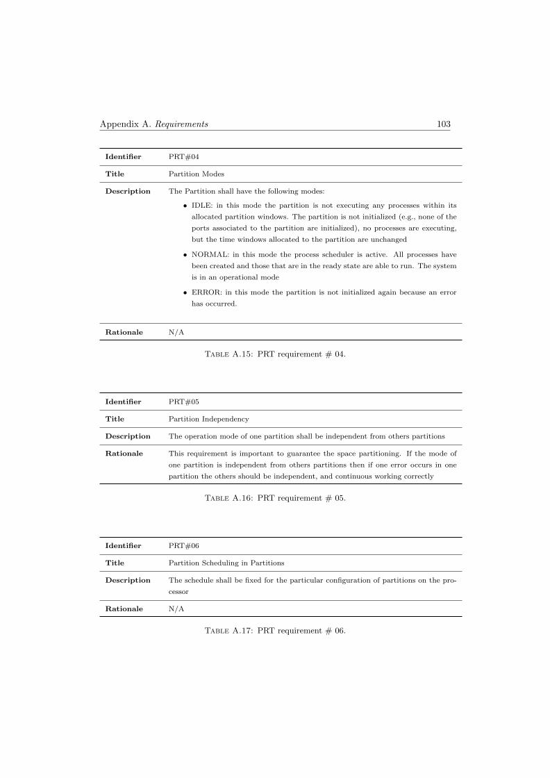
Appendix A. Requirements 103
Identifier PRT#04
Title Partition Modes
Description The Partition shall have the following modes:
• IDLE: in this mode the partition is not executing any processes within its
allocated partition windows. The partition is not initialized (e.g., none of the
ports associated to the partition are initialized), no processes are executing,
but the time windows allocated to the partition are unchanged
• NORMAL: in this mode the process scheduler is active. All processes have
been created and those that are in the ready state are able to run. The system
is in an operational mode
• ERROR: in this mode the partition is not initialized again because an error
has occurred.
Rationale N/A
Table A.15: PRT requirement # 04.
Identifier PRT#05
Title Partition Independency
Description The operation mode of one partition shall be independent from others partitions
Rationale This requirement is important to guarantee the space partitioning. If the mode of
one partition is independent from others partitions then if one error occurs in one
partition the others should be independent, and continuous working correctly
Table A.16: PRT requirement # 05.
Identifier PRT#06
Title Partition Scheduling in Partitions
Description The schedule shall be fixed for the particular configuration of partitions on the pro-
cessor
Rationale N/A
Table A.17: PRT requirement # 06.
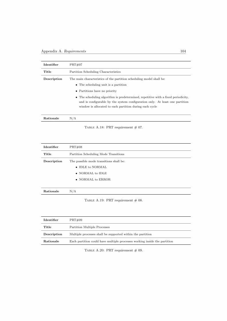
Appendix A. Requirements 104
Identifier PRT#07
Title Partition Scheduling Characteristics
Description The main characteristics of the partition scheduling model shall be:
• The scheduling unit is a partition
• Partitions have no priority
• The scheduling algorithm is predetermined, repetitive with a fixed periodicity,
and is configurable by the system configuration only. At least one partition
window is allocated to each partition during each cycle
Rationale N/A
Table A.18: PRT requirement # 07.
Identifier PRT#08
Title Partition Scheduling Mode Transitions
Description The possible mode transitions shall be:
• IDLE to NORMAL
• NORMAL to IDLE
• NORMAL to ERROR
Rationale N/A
Table A.19: PRT requirement # 08.
Identifier PRT#09
Title Partition Multiple Processes
Description Multiple processes shall be supported within the partition
Rationale Each partition could have multiple processes working inside the partition
Table A.20: PRT requirement # 09.
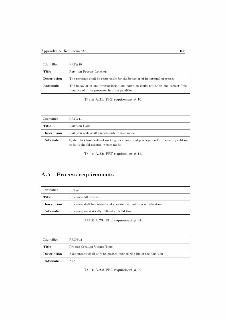
Appendix A. Requirements 105
Identifier PRT#10
Title Partition Process Isolation
Description The partition shall be responsible for the behavior of its internal processes
Rationale The behavior of one process inside one partition could not affect the correct func-
tionality of other processes in other partition
Table A.21: PRT requirement # 10.
Identifier PRT#11
Title Partition Code
Description Partition code shall execute only in user mode
Rationale System has two modes of working, user mode and privilege mode. In case of partition
code, it should execute in user mode
Table A.22: PRT requirement # 11.
A.5 Process requirements
Identifier PRC#01
Title Processes Allocation
Description Processes shall be created and allocated at partition initialization
Rationale Processes are statically defined at build time
Table A.23: PRC requirement # 01.
Identifier PRC#02
Title Process Creation Unique Time
Description Each process shall only be created once during life of the partition
Rationale N/A
Table A.24: PRC requirement # 02.
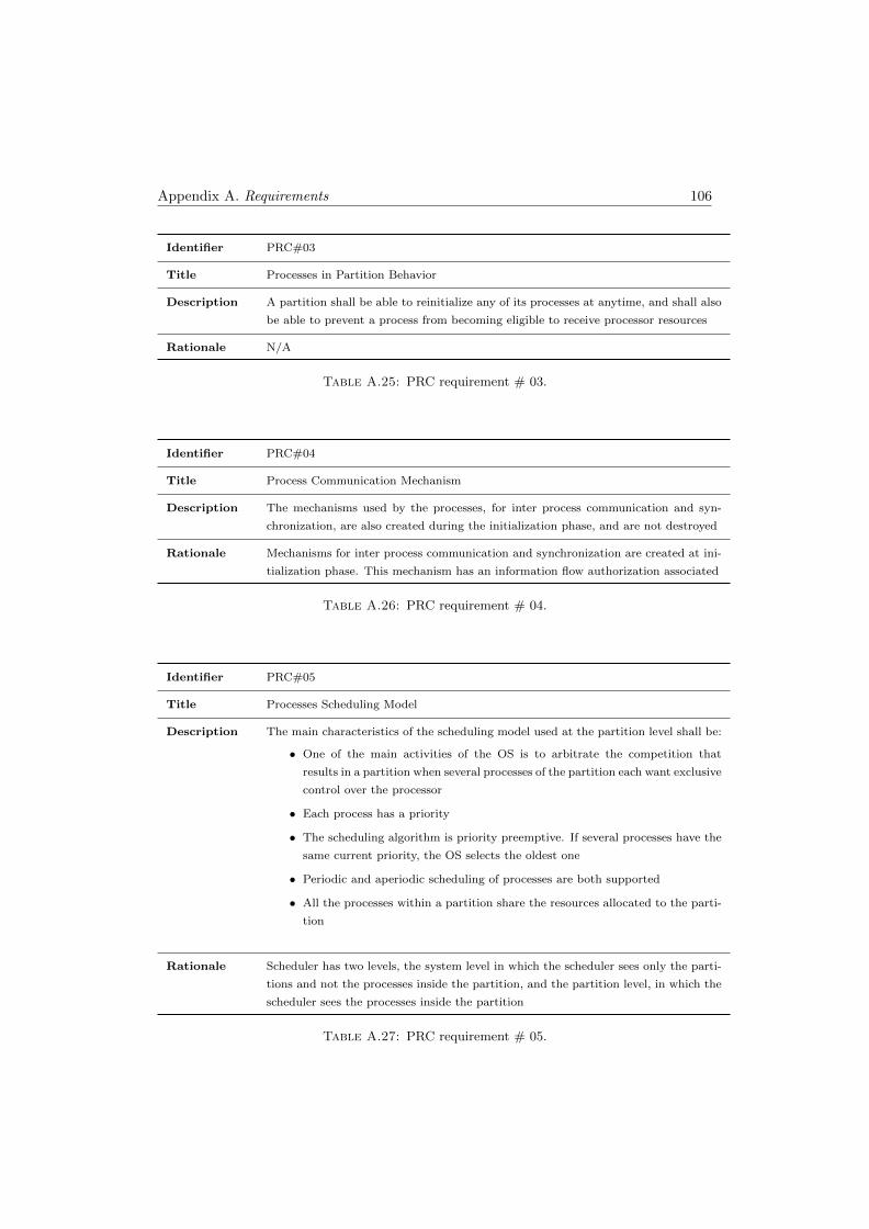
Appendix A. Requirements 106
Identifier PRC#03
Title Processes in Partition Behavior
Description A partition shall be able to reinitialize any of its processes at anytime, and shall also
be able to prevent a process from becoming eligible to receive processor resources
Rationale N/A
Table A.25: PRC requirement # 03.
Identifier PRC#04
Title Process Communication Mechanism
Description The mechanisms used by the processes, for inter process communication and syn-
chronization, are also created during the initialization phase, and are not destroyed
Rationale Mechanisms for inter process communication and synchronization are created at ini-
tialization phase. This mechanism has an information flow authorization associated
Table A.26: PRC requirement # 04.
Identifier PRC#05
Title Processes Scheduling Model
Description The main characteristics of the scheduling model used at the partition level shall be:
• One of the main activities of the OS is to arbitrate the competition that
results in a partition when several processes of the partition each want exclusive
control over the processor
• Each process has a priority
• The scheduling algorithm is priority preemptive. If several processes have the
same current priority, the OS selects the oldest one
• Periodic and aperiodic scheduling of processes are both supported
• All the processes within a partition share the resources allocated to the parti-
tion
Rationale Scheduler has two levels, the system level in which the scheduler sees only the parti-
tions and not the processes inside the partition, and the partition level, in which the
scheduler sees the processes inside the partition
Table A.27: PRC requirement # 05.
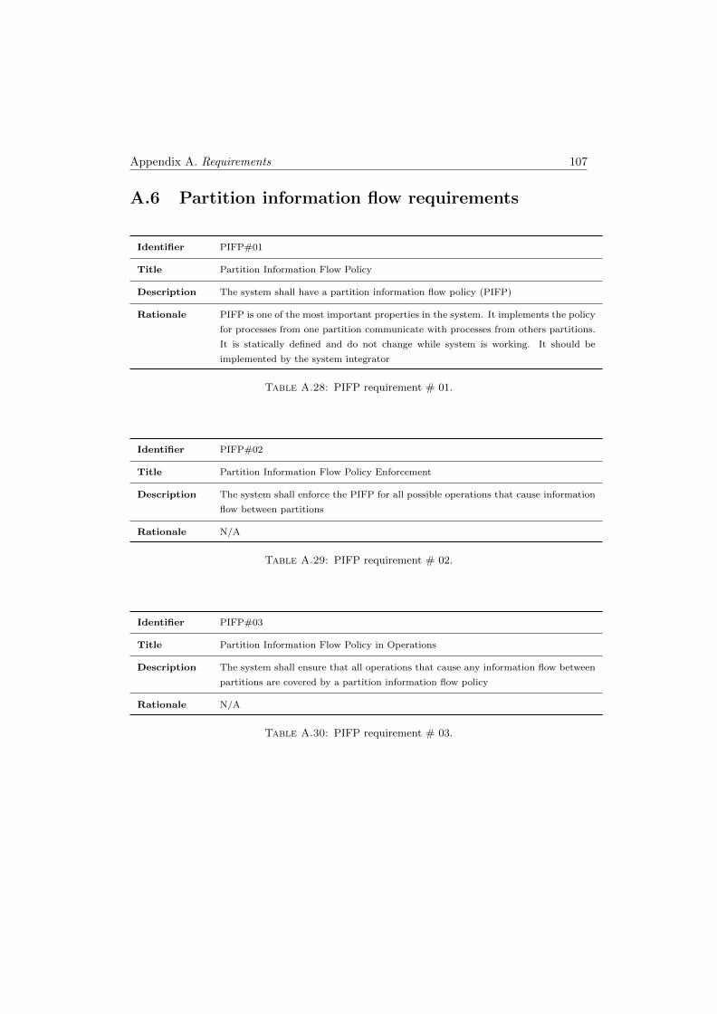
Appendix A. Requirements 107
A.6 Partition information flow requirements
Identifier PIFP#01
Title Partition Information Flow Policy
Description The system shall have a partition information flow policy (PIFP)
Rationale PIFP is one of the most important properties in the system. It implements the policy
for processes from one partition communicate with processes from others partitions.
It is statically defined and do not change while system is working. It should be
implemented by the system integrator
Table A.28: PIFP requirement # 01.
Identifier PIFP#02
Title Partition Information Flow Policy Enforcement
Description The system shall enforce the PIFP for all possible operations that cause information
flow between partitions
Rationale N/A
Table A.29: PIFP requirement # 02.
Identifier PIFP#03
Title Partition Information Flow Policy in Operations
Description The system shall ensure that all operations that cause any information flow between
partitions are covered by a partition information flow policy
Rationale N/A
Table A.30: PIFP requirement # 03.
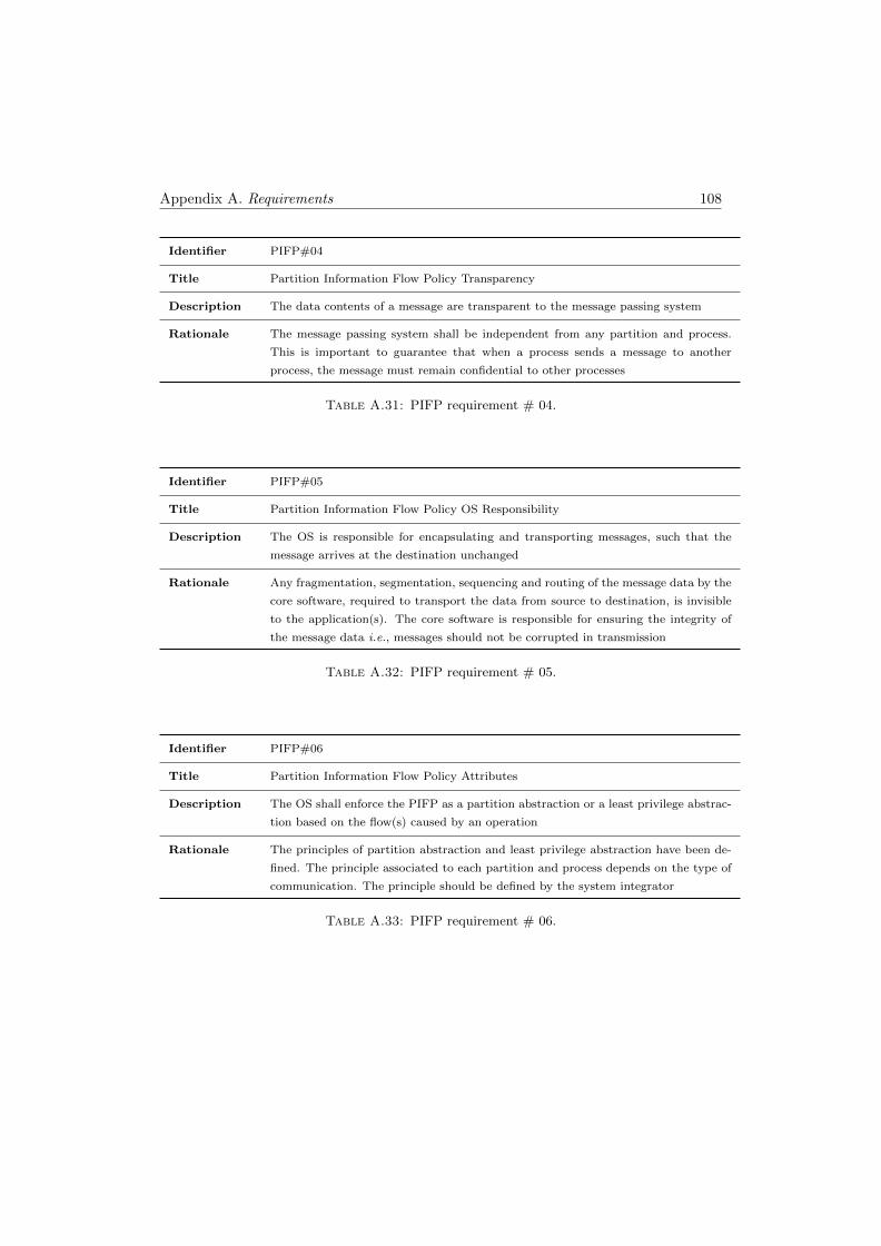
Appendix A. Requirements 108
Identifier PIFP#04
Title Partition Information Flow Policy Transparency
Description The data contents of a message are transparent to the message passing system
Rationale The message passing system shall be independent from any partition and process.
This is important to guarantee that when a process sends a message to another
process, the message must remain confidential to other processes
Table A.31: PIFP requirement # 04.
Identifier PIFP#05
Title Partition Information Flow Policy OS Responsibility
Description The OS is responsible for encapsulating and transporting messages, such that the
message arrives at the destination unchanged
Rationale Any fragmentation, segmentation, sequencing and routing of the message data by the
core software, required to transport the data from source to destination, is invisible
to the application(s). The core software is responsible for ensuring the integrity of
the message data i.e., messages should not be corrupted in transmission
Table A.32: PIFP requirement # 05.
Identifier PIFP#06
Title Partition Information Flow Policy Attributes
Description The OS shall enforce the PIFP as a partition abstraction or a least privilege abstrac-
tion based on the flow(s) caused by an operation
Rationale The principles of partition abstraction and least privilege abstraction have been de-
fined. The principle associated to each partition and process depends on the type of
communication. The principle should be defined by the system integrator
Table A.33: PIFP requirement # 06.
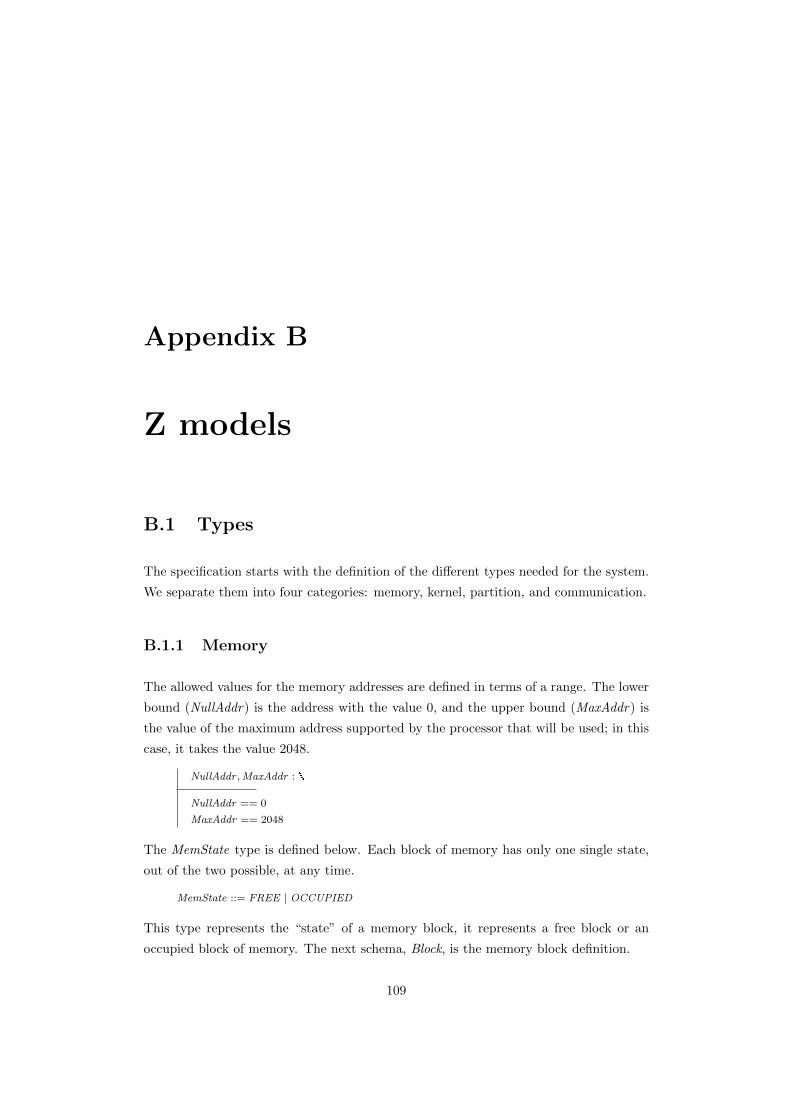
Appendix B
Z models
B.1 Types
The specification starts with the definition of the different types needed for the system.
We separate them into four categories: memory, kernel, partition, and communication.
B.1.1 Memory
The allowed values for the memory addresses are defined in terms of a range. The lower
bound (NullAddr) is the address with the value 0, and the upper bound (MaxAddr) is
the value of the maximum address supported by the processor that will be used; in this
case, it takes the value 2048.
NullAddr ,MaxAddr :
NullAddr == 0
MaxAddr == 2048
The MemState type is defined below. Each block of memory has only one single state,
out of the two possible, at any time.
MemState ::= FREE | OCCUPIED
This type represents the “state” of a memory block, it represents a free block or an
occupied block of memory. The next schema, Block, is the memory block definition.
109
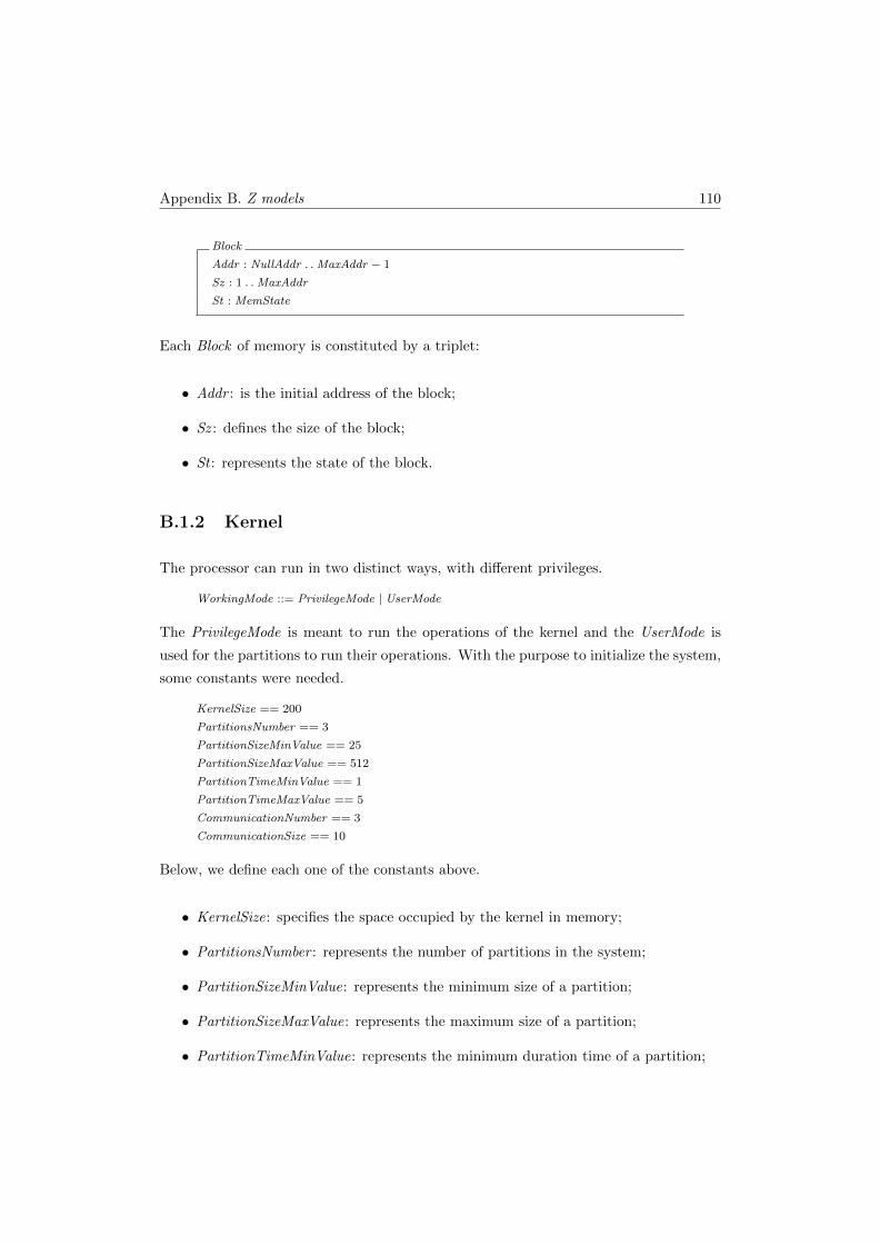
Appendix B. Z models 110
Block
Addr : NullAddr . .MaxAddr − 1
Sz : 1 . .MaxAddr
St : MemState
Each Block of memory is constituted by a triplet:
• Addr : is the initial address of the block;
• Sz : defines the size of the block;
• St : represents the state of the block.
B.1.2 Kernel
The processor can run in two distinct ways, with different privileges.
WorkingMode ::= PrivilegeMode | UserMode
The PrivilegeMode is meant to run the operations of the kernel and the UserMode is
used for the partitions to run their operations. With the purpose to initialize the system,
some constants were needed.
KernelSize == 200
PartitionsNumber == 3
PartitionSizeMinValue == 25
PartitionSizeMaxValue == 512
PartitionTimeMinValue == 1
PartitionTimeMaxValue == 5
CommunicationNumber == 3
CommunicationSize == 10
Below, we define each one of the constants above.
• KernelSize: specifies the space occupied by the kernel in memory;
• PartitionsNumber : represents the number of partitions in the system;
• PartitionSizeMinValue: represents the minimum size of a partition;
• PartitionSizeMaxValue: represents the maximum size of a partition;
• PartitionTimeMinValue: represents the minimum duration time of a partition;
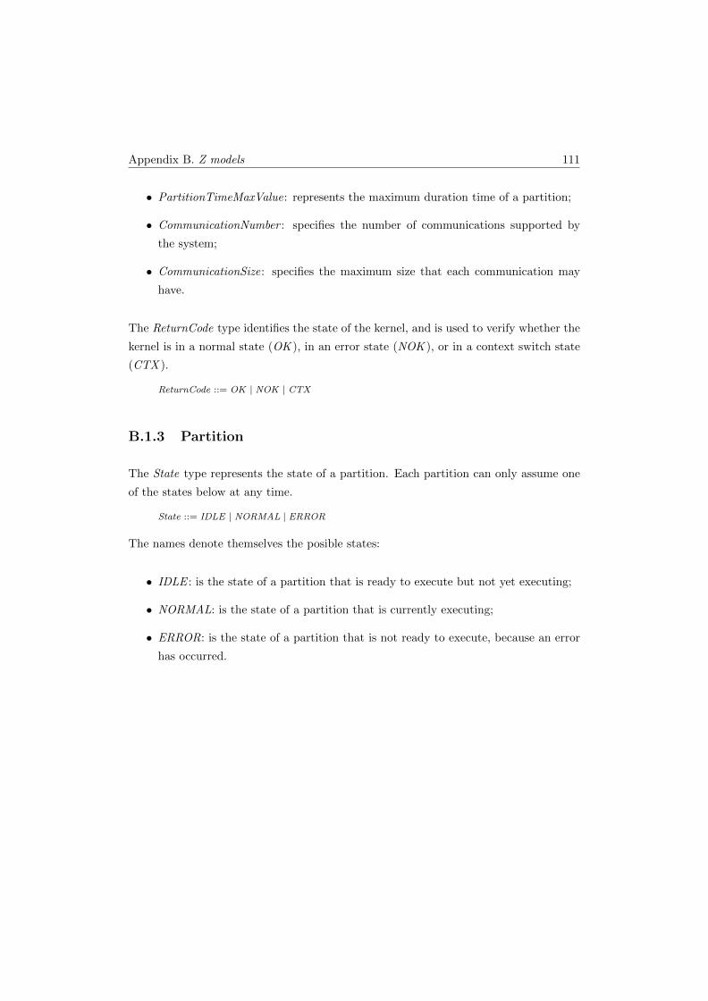
Appendix B. Z models 111
• PartitionTimeMaxValue: represents the maximum duration time of a partition;
• CommunicationNumber : specifies the number of communications supported by
the system;
• CommunicationSize: specifies the maximum size that each communication may
have.
The ReturnCode type identifies the state of the kernel, and is used to verify whether the
kernel is in a normal state (OK ), in an error state (NOK ), or in a context switch state
(CTX ).
ReturnCode ::= OK | NOK | CTX
B.1.3 Partition
The State type represents the state of a partition. Each partition can only assume one
of the states below at any time.
State ::= IDLE | NORMAL | ERROR
The names denote themselves the posible states:
• IDLE : is the state of a partition that is ready to execute but not yet executing;
• NORMAL: is the state of a partition that is currently executing;
• ERROR: is the state of a partition that is not ready to execute, because an error
has occurred.
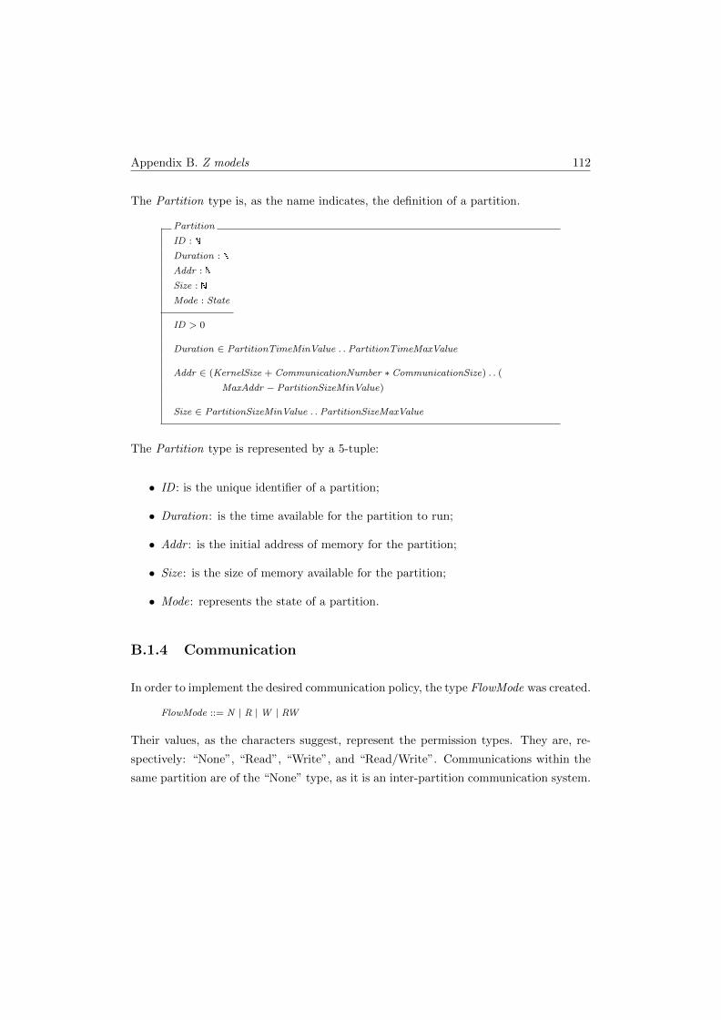
Appendix B. Z models 112
The Partition type is, as the name indicates, the definition of a partition.
Partition
ID :
Duration :
Addr :
Size :
Mode : State
ID > 0
Duration ∈ PartitionTimeMinValue . . PartitionTimeMaxValue
Addr ∈ (KernelSize + CommunicationNumber ∗ CommunicationSize) . . (
MaxAddr − PartitionSizeMinValue)
Size ∈ PartitionSizeMinValue . . PartitionSizeMaxValue
The Partition type is represented by a 5-tuple:
• ID : is the unique identifier of a partition;
• Duration: is the time available for the partition to run;
• Addr : is the initial address of memory for the partition;
• Size: is the size of memory available for the partition;
• Mode: represents the state of a partition.
B.1.4 Communication
In order to implement the desired communication policy, the type FlowMode was created.
FlowMode ::= N | R |W | RW
Their values, as the characters suggest, represent the permission types. They are, re-
spectively: “None”, “Read”, “Write”, and “Read/Write”. Communications within the
same partition are of the “None” type, as it is an inter-partition communication system.
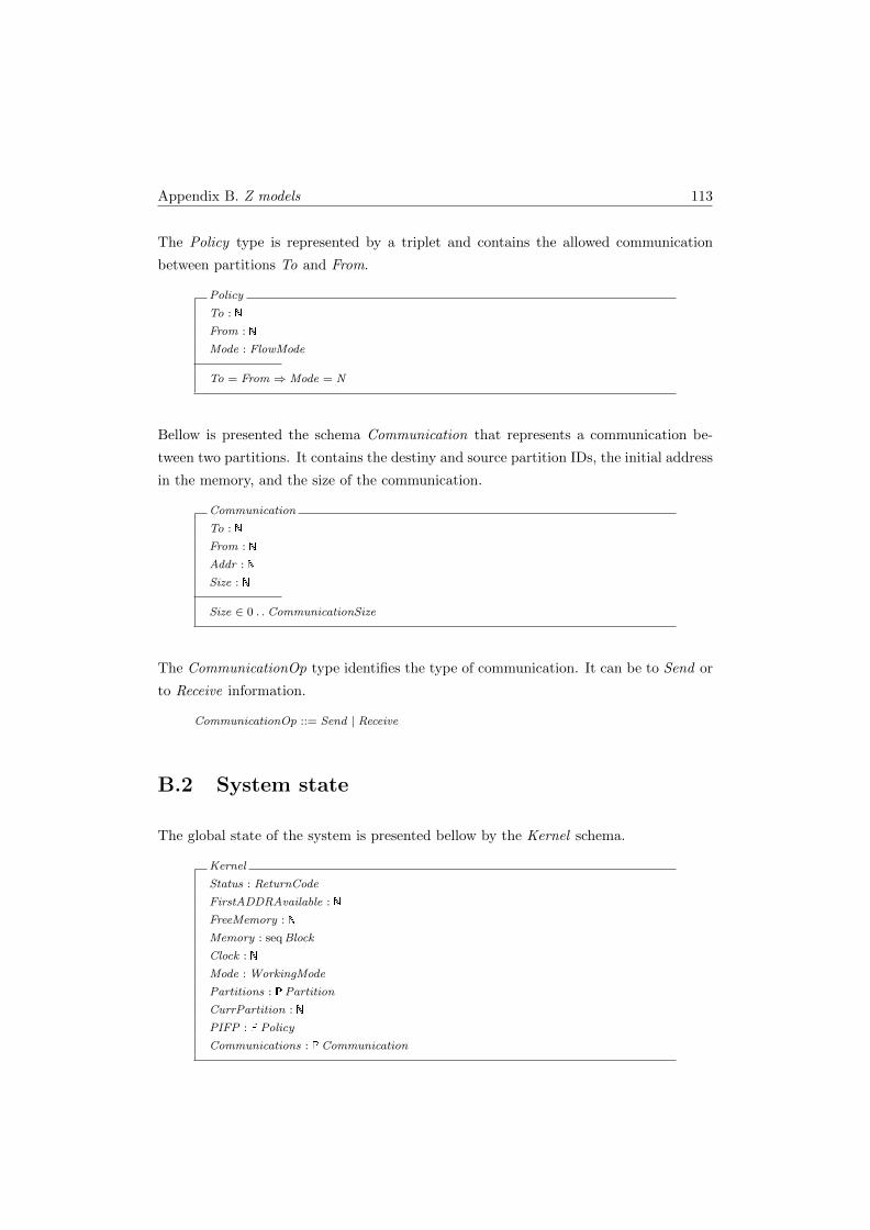
Appendix B. Z models 113
The Policy type is represented by a triplet and contains the allowed communication
between partitions To and From.
Policy
To :
From :
Mode : FlowMode
To = From ⇒ Mode = N
Bellow is presented the schema Communication that represents a communication be-
tween two partitions. It contains the destiny and source partition IDs, the initial address
in the memory, and the size of the communication.
Communication
To :
From :
Addr :
Size :
Size ∈ 0 . . CommunicationSize
The CommunicationOp type identifies the type of communication. It can be to Send or
to Receive information.
CommunicationOp ::= Send | Receive
B.2 System state
The global state of the system is presented bellow by the Kernel schema.
Kernel
Status : ReturnCode
FirstADDRAvailable :
FreeMemory :
Memory : seqBlock
Clock :
Mode : WorkingMode
Partitions : �Partition
CurrPartition :
PIFP : �Policy
Communications : �Communication
Appendix B. Z models 114
The kernel is represented by:
• Status: represents the state of the system, it is updated along the time by the
operations;
• FirstADDRAvailable: assumes the first address of free memory;
• FreeMemory : assumes the size of free memory;
• Memory : is constituted by a sequence of memory blocks;
• Clock : is the representation of the elapsed time;
• Mode: shows the working mode allowed at the moment;
• Partitions: a set with the system partitions;
• CurrPartition: represents the running partition;
• PIFP : a set that contains the communications policies for all the system partitions;
• Communications: a set that contains the communications performed by the sys-
tem.
This global system state is changed, along the time, by the operations executed. These
operations were divided into four categories: 1)Initialization operations: that deal with
the initialization of the system; 2)Partition operations: that comprise the operations
of the partitions; 3)User operations: contain the operations that can run in UserMode;
4)Kernel operations: comprise the operations that can run in PrivilegeMode.
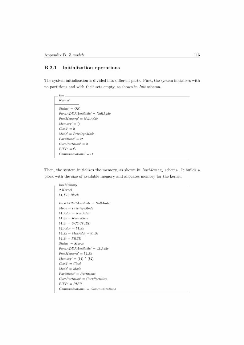
Appendix B. Z models 115
B.2.1 Initialization operations
The system initialization is divided into different parts. First, the system initializes with
no partitions and with their sets empty, as shown in Init schema.
Init
Kernel ′
Status′ = OK
FirstADDRAvailable′ = NullAddr
FreeMemory ′ = NullAddr
Memory ′ = 〈〉Clock ′ = 0
Mode′ = PrivilegeMode
Partitions′ = �
CurrPartition ′ = 0
PIFP ′ = �
Communications′ = �
Then, the system initializes the memory, as shown in InitMemory schema. It builds a
block with the size of available memory and allocates memory for the kernel.
InitMemory
∆Kernel
b1, b2 : Block
FirstADDRAvailable = NullAddr
Mode = PrivilegeMode
b1.Addr = NullAddr
b1.Sz = KernelSize
b1.St = OCCUPIED
b2.Addr = b1.Sz
b2.Sz = MaxAddr − b1.Sz
b2.St = FREE
Status′ = Status
FirstADDRAvailable′ = b2.Addr
FreeMemory ′ = b2.Sz
Memory ′ = 〈b1〉 � 〈b2〉Clock ′ = Clock
Mode′ = Mode
Partitions′ = Partitions
CurrPartition ′ = CurrPartition
PIFP ′ = PIFP
Communications′ = Communications

Appendix B. Z models 116
After that, the system communications are initialized by InitCommunications schema
with the defined size for communications.
InitCommunications
∆Kernel
b1, b2 : Block
c : Communication
FirstADDRAvailable 6= NullAddr
Mode = PrivilegeMode
#Communications < CommunicationNumber
b1.Addr = FirstADDRAvailable
b1.Sz = CommunicationSize
b1.St = OCCUPIED
b2.Addr = b1.Addr + b1.Sz
b2.Sz = FreeMemory − b1.Sz
b2.St = FREE
c.To = 0
c.From = 0
c.Addr = b1.Addr
c.Size = 0
Status′ = Status
FirstADDRAvailable′ = b2.Addr
FreeMemory ′ = b2.Sz
Memory ′ = front Memory � 〈b1〉 � 〈b2〉Clock ′ = Clock
Mode′ = Mode
Partitions′ = Partitions
CurrPartition ′ = CurrPartition
PIFP ′ = PIFP
Communications′ = Communications ∪ {c}
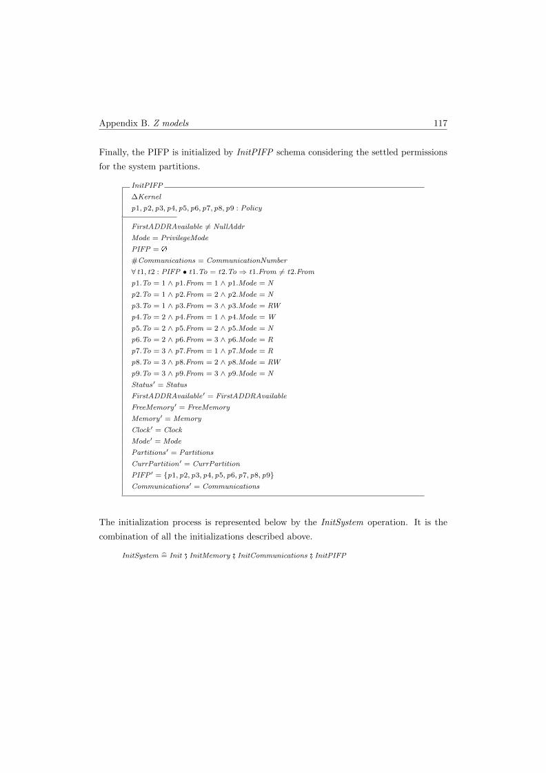
Appendix B. Z models 117
Finally, the PIFP is initialized by InitPIFP schema considering the settled permissions
for the system partitions.
InitPIFP
∆Kernel
p1, p2, p3, p4, p5, p6, p7, p8, p9 : Policy
FirstADDRAvailable 6= NullAddr
Mode = PrivilegeMode
PIFP = �
#Communications = CommunicationNumber
∀ t1, t2 : PIFP • t1.To = t2.To ⇒ t1.From 6= t2.From
p1.To = 1 ∧ p1.From = 1 ∧ p1.Mode = N
p2.To = 1 ∧ p2.From = 2 ∧ p2.Mode = N
p3.To = 1 ∧ p3.From = 3 ∧ p3.Mode = RW
p4.To = 2 ∧ p4.From = 1 ∧ p4.Mode = W
p5.To = 2 ∧ p5.From = 2 ∧ p5.Mode = N
p6.To = 2 ∧ p6.From = 3 ∧ p6.Mode = R
p7.To = 3 ∧ p7.From = 1 ∧ p7.Mode = R
p8.To = 3 ∧ p8.From = 2 ∧ p8.Mode = RW
p9.To = 3 ∧ p9.From = 3 ∧ p9.Mode = N
Status′ = Status
FirstADDRAvailable′ = FirstADDRAvailable
FreeMemory ′ = FreeMemory
Memory ′ = Memory
Clock ′ = Clock
Mode′ = Mode
Partitions′ = Partitions
CurrPartition ′ = CurrPartition
PIFP ′ = {p1, p2, p3, p4, p5, p6, p7, p8, p9}Communications′ = Communications
The initialization process is represented below by the InitSystem operation. It is the
combination of all the initializations described above.
InitSystem = Init � InitMemory � InitCommunications � InitPIFP

Appendix B. Z models 118
B.2.2 Partiton operations
The NewPartition schema creates a new partition in the system. For this purpose, it
receives the ID (id? ), the duration (d? ), and the size (s? ) as parameters.
NewPartition
∆Kernel
id?, d?, s? :
b1, b2 : Block
p : Partition
Mode = PrivilegeMode
#Partitions < PartitionsNumber
PIFP 6= �
∀ pr : Partition | pr ∈ Partitions • pr .ID 6= id?
id? ∈ 1 . . PartitionsNumber
d? ∈ PartitionTimeMinValue . . PartitionTimeMaxValue
s? ∈ PartitionSizeMinValue . . PartitionSizeMaxValue
s? ∈ 1 . . FreeMemory
b1.Addr = FirstADDRAvailable
b1.Sz = s?
b1.St = OCCUPIED
b2.Addr = FirstADDRAvailable + b1.Sz
b2.Sz = FreeMemory − b1.Sz
b2.St = FREE
p /∈ Partitions
p.ID = id?
p.Duration = d?
p.Addr = FirstADDRAvailable
p.Size = s?
p.Mode = IDLE
Status′ = Status
FirstADDRAvailable′ = b2.Addr
FreeMemory ′ = b2.Sz
Memory ′ = front Memory � 〈b1〉 � 〈b2〉Clock ′ = Clock
Mode′ = Mode
Partitions′ = Partitions ∪ {p}CurrPartition ′ = CurrPartition
PIFP ′ = PIFP
Communications′ = Communications

Appendix B. Z models 119
In PartitonResumes schema, a partition that is ready (the CurrPartition) enters the
critical section and is then activated - its mode is changed from IDLE to NORMAL.
The partition can only become active if no other partition is active.
PartitonResumes
∆Kernel
p1, p2 : Partition
Status = OK
Mode = PrivilegeMode
#Partitions = PartitionsNumber
¬ (∃ p : Partition | p ∈ Partitions • p.Mode = NORMAL)
p1 ∈ Partitions
p1.ID = CurrPartition
p1.Mode = IDLE
p2.ID = p1.ID
p2.Duration = p1.Duration
p2.Addr = p1.Addr
p2.Size = p1.Size
p2.Mode = NORMAL
Status′ = Status
FirstADDRAvailable′ = FirstADDRAvailable
FreeMemory ′ = FreeMemory
Memory ′ = Memory
Clock ′ = Clock
Mode′ = UserMode
Partitions′ = (Partitions \ {p1}) ∪ {p2}CurrPartition ′ = CurrPartition
PIFP ′ = PIFP
Communications′ = Communications
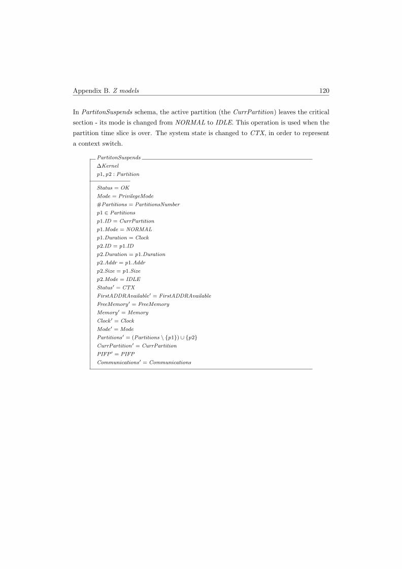
Appendix B. Z models 120
In PartitonSuspends schema, the active partition (the CurrPartition) leaves the critical
section - its mode is changed from NORMAL to IDLE. This operation is used when the
partition time slice is over. The system state is changed to CTX, in order to represent
a context switch.
PartitonSuspends
∆Kernel
p1, p2 : Partition
Status = OK
Mode = PrivilegeMode
#Partitions = PartitionsNumber
p1 ∈ Partitions
p1.ID = CurrPartition
p1.Mode = NORMAL
p1.Duration = Clock
p2.ID = p1.ID
p2.Duration = p1.Duration
p2.Addr = p1.Addr
p2.Size = p1.Size
p2.Mode = IDLE
Status′ = CTX
FirstADDRAvailable′ = FirstADDRAvailable
FreeMemory ′ = FreeMemory
Memory ′ = Memory
Clock ′ = Clock
Mode′ = Mode
Partitions′ = (Partitions \ {p1}) ∪ {p2}CurrPartition ′ = CurrPartition
PIFP ′ = PIFP
Communications′ = Communications
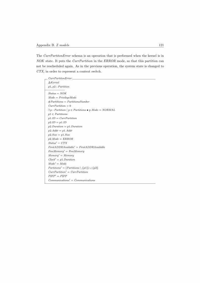
Appendix B. Z models 121
The CurrPartitonError schema is an operation that is performed when the kernel is in
NOK state. It puts the CurrPartition in the ERROR mode, so that this partition can
not be rescheduled again. As in the previous operation, the system state is changed to
CTX, in order to represent a context switch.
CurrPartitonError
∆Kernel
p1, p2 : Partition
Status = NOK
Mode = PrivilegeMode
#Partitions = PartitionsNumber
CurrPartition > 0
∃ p : Partition | p ∈ Partitions • p.Mode = NORMAL
p1 ∈ Partitions
p1.ID = CurrPartition
p2.ID = p1.ID
p2.Duration = p1.Duration
p2.Addr = p1.Addr
p2.Size = p1.Size
p2.Mode = ERROR
Status′ = CTX
FirstADDRAvailable′ = FirstADDRAvailable
FreeMemory ′ = FreeMemory
Memory ′ = Memory
Clock ′ = p1.Duration
Mode′ = Mode
Partitions′ = (Partitions \ {p1}) ∪ {p2}CurrPartition ′ = CurrPartition
PIFP ′ = PIFP
Communications′ = Communications

Appendix B. Z models 122
The GetDuration schema, does not change the system state. This is a read operation
and it returns the allowed duration (the time slice) of a given partition.
GetDuration
ΞKernel
id? :
time! :
p : Partition
Status = OK
Mode = PrivilegeMode
#Partitions = PartitionsNumber
time! = p.Duration
p ∈ Partitions
p.ID = id?

Appendix B. Z models 123
B.2.3 User operations
For the purpose of this work, both the read and write operations were implemented as
a single operation, ReadWrite. This was because the concern is only on whether the
operation can access a particular memory space. The ReadWrite operation receives, as
parameters, the address (a? ) and the size (s? ) of memory that it wants to access. If
the desired memory space belongs to the CurrPartition, the system state remains OK,
otherwise, it is changed to NOK.
ReadWrite
∆Kernel
a? :
s? :
p : Partition
Status = OK
Mode = UserMode
s? > 0
p ∈ Partitions
p.ID = CurrPartition
p.Mode = NORMAL
Status′ = if (p.Addr ≤ a? ∧ (p.Addr + p.Size ≥ a? + s?))
then (OK ) else (NOK )
FirstADDRAvailable′ = FirstADDRAvailable
FreeMemory ′ = FreeMemory
Memory ′ = Memory
Clock ′ = Clock
Mode′ = Mode
Partitions′ = Partitions
CurrPartition ′ = CurrPartition
PIFP ′ = PIFP
Communications′ = Communications
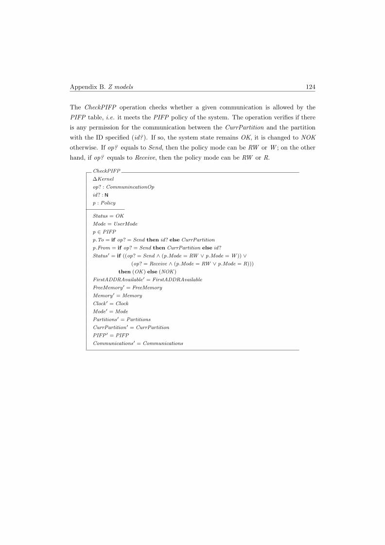
Appendix B. Z models 124
The CheckPIFP operation checks whether a given communication is allowed by the
PIFP table, i.e. it meets the PIFP policy of the system. The operation verifies if there
is any permission for the communication between the CurrPartition and the partition
with the ID specified (id? ). If so, the system state remains OK, it is changed to NOK
otherwise. If op? equals to Send, then the policy mode can be RW or W ; on the other
hand, if op? equals to Receive, then the policy mode can be RW or R.
CheckPIFP
∆Kernel
op? : CommunincationOp
id? :
p : Policy
Status = OK
Mode = UserMode
p ∈ PIFP
p.To = if op? = Send then id? else CurrPartition
p.From = if op? = Send then CurrPartition else id?
Status′ = if ((op? = Send ∧ (p.Mode = RW ∨ p.Mode = W )) ∨(op? = Receive ∧ (p.Mode = RW ∨ p.Mode = R)))
then (OK ) else (NOK )
FirstADDRAvailable′ = FirstADDRAvailable
FreeMemory ′ = FreeMemory
Memory ′ = Memory
Clock ′ = Clock
Mode′ = Mode
Partitions′ = Partitions
CurrPartition ′ = CurrPartition
PIFP ′ = PIFP
Communications′ = Communications
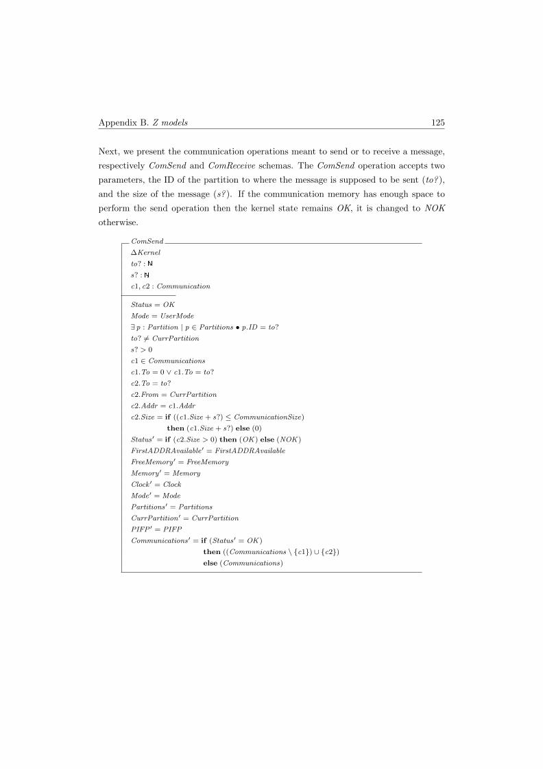
Appendix B. Z models 125
Next, we present the communication operations meant to send or to receive a message,
respectively ComSend and ComReceive schemas. The ComSend operation accepts two
parameters, the ID of the partition to where the message is supposed to be sent (to? ),
and the size of the message (s? ). If the communication memory has enough space to
perform the send operation then the kernel state remains OK, it is changed to NOK
otherwise.
ComSend
∆Kernel
to? :
s? :
c1, c2 : Communication
Status = OK
Mode = UserMode
∃ p : Partition | p ∈ Partitions • p.ID = to?
to? 6= CurrPartition
s? > 0
c1 ∈ Communications
c1.To = 0 ∨ c1.To = to?
c2.To = to?
c2.From = CurrPartition
c2.Addr = c1.Addr
c2.Size = if ((c1.Size + s?) ≤ CommunicationSize)
then (c1.Size + s?) else (0)
Status′ = if (c2.Size > 0) then (OK ) else (NOK )
FirstADDRAvailable′ = FirstADDRAvailable
FreeMemory ′ = FreeMemory
Memory ′ = Memory
Clock ′ = Clock
Mode′ = Mode
Partitions′ = Partitions
CurrPartition ′ = CurrPartition
PIFP ′ = PIFP
Communications′ = if (Status′ = OK )
then ((Communications \ {c1}) ∪ {c2})else (Communications)
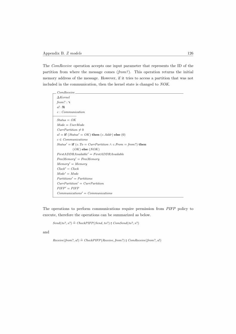
Appendix B. Z models 126
The ComReceive operation accepts one input parameter that represents the ID of the
partition from where the message comes (from? ). This operation returns the initial
memory address of the message. However, if it tries to access a partition that was not
included in the communication, then the kernel state is changed to NOK.
ComReceive
∆Kernel
from? :
a! :
c : Communication
Status = OK
Mode = UserMode
CurrPartition 6= 0
a! = if (Status′ = OK ) then (c.Addr) else (0)
c ∈ Communications
Status′ = if (c.To = CurrPartition ∧ c.From = from?) then
(OK ) else (NOK )
FirstADDRAvailable′ = FirstADDRAvailable
FreeMemory ′ = FreeMemory
Memory ′ = Memory
Clock ′ = Clock
Mode′ = Mode
Partitions′ = Partitions
CurrPartition ′ = CurrPartition
PIFP ′ = PIFP
Communications′ = Communications
The operations to perform communications require permission from PIFP policy to
execute, therefore the operations can be summarized as below.
Send(to?, s?) = CheckPIFP(Send , to?) � ComSend(to?, s?)
and
Receive(from?, a!) = CheckPIFP(Receive, from?) � ComReceive(from?, a!)
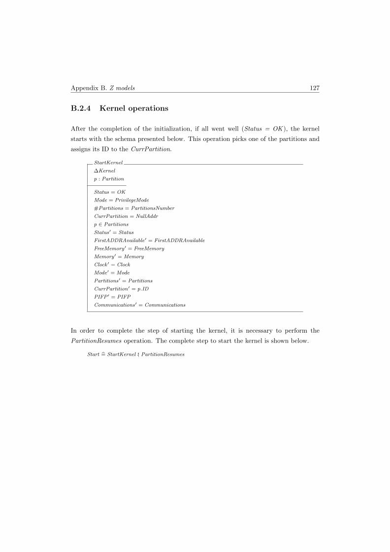
Appendix B. Z models 127
B.2.4 Kernel operations
After the completion of the initialization, if all went well (Status = OK ), the kernel
starts with the schema presented below. This operation picks one of the partitions and
assigns its ID to the CurrPartition.
StartKernel
∆Kernel
p : Partition
Status = OK
Mode = PrivilegeMode
#Partitions = PartitionsNumber
CurrPartition = NullAddr
p ∈ Partitions
Status′ = Status
FirstADDRAvailable′ = FirstADDRAvailable
FreeMemory ′ = FreeMemory
Memory ′ = Memory
Clock ′ = Clock
Mode′ = Mode
Partitions′ = Partitions
CurrPartition ′ = p.ID
PIFP ′ = PIFP
Communications′ = Communications
In order to complete the step of starting the kernel, it is necessary to perform the
PartitionResumes operation. The complete step to start the kernel is shown below.
Start = StartKernel � PartitionResumes

Appendix B. Z models 128
The UpdateComTable schema is utilized to update the communication table, deleting
the entries that have both a To partition that has just run, and a To partition that has
in ERROR mode. This operation is performed in the context switch mechanism.
UpdateComTable
∆Kernel
p : Partition
c1, c2 : Communication
Status = CTX
Mode = PrivilegeMode
p ∈ Partitions
p.Mode = ERROR
c1 ∈ Communications
c1.To = CurrPartition ∨ c1.To = p.ID
c2.To = 0
c2.From = 0
c2.Addr = c1.Addr
c2.Size = CommunicationSize
Status′ = Status
FirstADDRAvailable′ = FirstADDRAvailable
FreeMemory ′ = FreeMemory
Memory ′ = Memory
Clock ′ = Clock
Mode′ = Mode
Partitions′ = Partitions
CurrPartition ′ = CurrPartition
PIFP ′ = PIFP
Communications′ = (Communications \ {c1}) ∪ {c2}
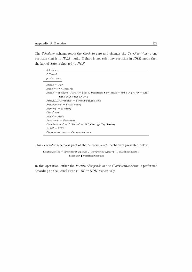
Appendix B. Z models 129
The Scheduler schema resets the Clock to zero and changes the CurrPartition to one
partition that is in IDLE mode. If there is not exist any partition in IDLE mode then
the kernel state is changed to NOK.
Scheduler
∆Kernel
p : Partition
Status = CTX
Mode = PrivilegeMode
Status′ = if (∃ prt : Partition | prt ∈ Partitions • prt .Mode = IDLE ∧ prt .ID = p.ID)
then (OK ) else (NOK )
FirstADDRAvailable′ = FirstADDRAvailable
FreeMemory ′ = FreeMemory
Memory ′ = Memory
Clock ′ = 0
Mode′ = Mode
Partitions′ = Partitions
CurrPartition ′ = if (Status′ = OK ) then (p.ID) else (0)
PIFP ′ = PIFP
Communications′ = Communications
This Scheduler schema is part of the ContextSwitch mechanism presented below.
ContextSwitch = (PartitionSuspends ∨ CurrPartitonError) � UpdateComTable �
Scheduler � PartitionResumes
In this operation, either the PartitionSuspends or the CurrPartitonError is performed
according to the kernel state is OK or NOK respectively.
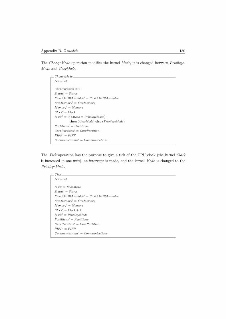
Appendix B. Z models 130
The ChangeMode operation modifies the kernel Mode, it is changed between Privilege-
Mode and UserMode.
ChangeMode
∆Kernel
CurrPartition 6= 0
Status′ = Status
FirstADDRAvailable′ = FirstADDRAvailable
FreeMemory ′ = FreeMemory
Memory ′ = Memory
Clock ′ = Clock
Mode′ = if (Mode = PrivilegeMode)
then (UserMode) else (PrivilegeMode)
Partitions′ = Partitions
CurrPartition ′ = CurrPartition
PIFP ′ = PIFP
Communications′ = Communications
The Tick operation has the purpose to give a tick of the CPU clock (the kernel Clock
is increased in one unit), an interrupt is made, and the kernel Mode is changed to the
PrivilegeMode.
Tick
∆Kernel
Mode = UserMode
Status′ = Status
FirstADDRAvailable′ = FirstADDRAvailable
FreeMemory ′ = FreeMemory
Memory ′ = Memory
Clock ′ = Clock + 1
Mode′ = PrivilegeMode
Partitions′ = Partitions
CurrPartition ′ = CurrPartition
PIFP ′ = PIFP
Communications′ = Communications
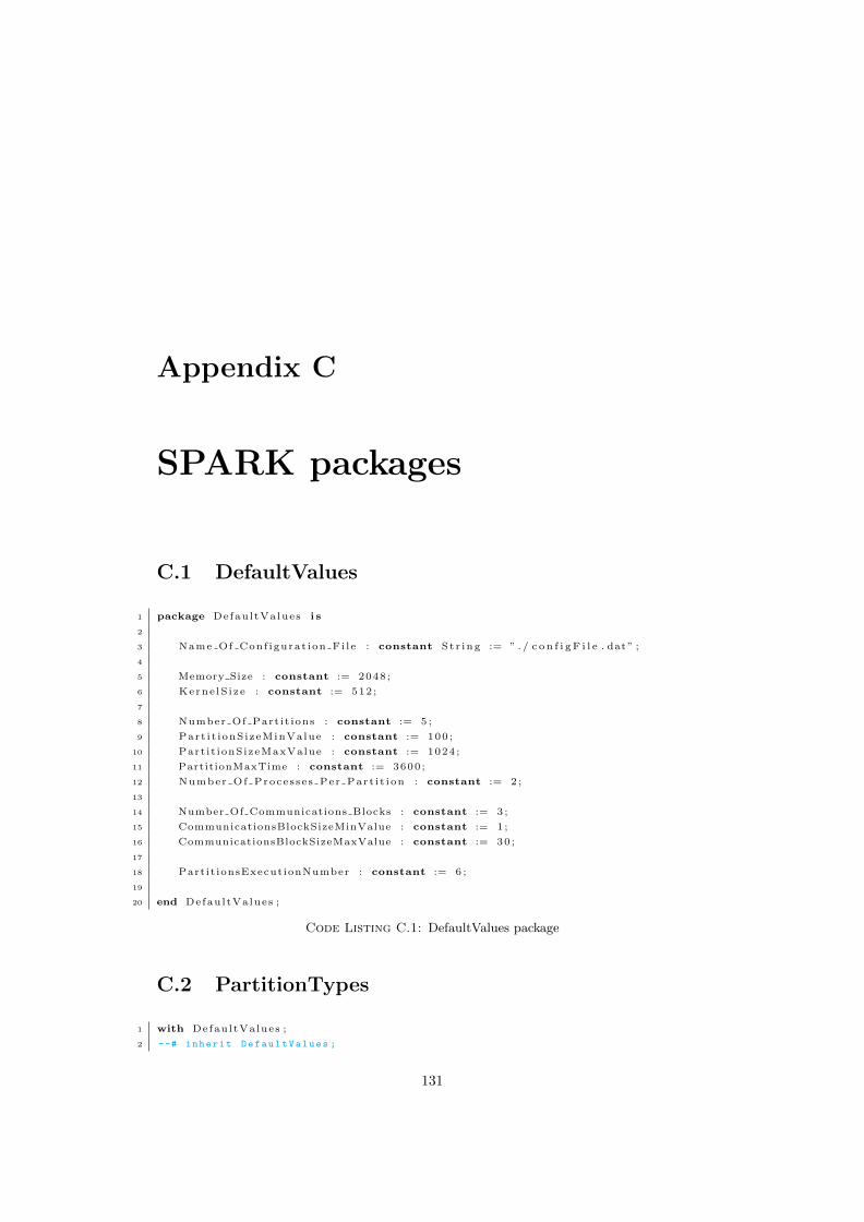
Appendix C
SPARK packages
C.1 DefaultValues
1 package DefaultValues i s
2
3 Name Of Conf igurat ion Fi le : constant St r ing := ” . / c o n f i g F i l e . dat” ;
4
5 Memory Size : constant := 2048 ;
6 Kerne lS i ze : constant := 512 ;
7
8 Number Of Part it ions : constant := 5 ;
9 Part i t ionSizeMinValue : constant := 100 ;
10 Part it ionSizeMaxValue : constant := 1024 ;
11 PartitionMaxTime : constant := 3600 ;
12 Number Of Processes Per Part i t ion : constant := 2 ;
13
14 Number Of Communications Blocks : constant := 3 ;
15 CommunicationsBlockSizeMinValue : constant := 1 ;
16 CommunicationsBlockSizeMaxValue : constant := 30 ;
17
18 Partit ionsExecutionNumber : constant := 6 ;
19
20 end DefaultValues ;
Code Listing C.1: DefaultValues package
C.2 PartitionTypes
1 with DefaultValues ;
2 --# inherit DefaultValues ;
131
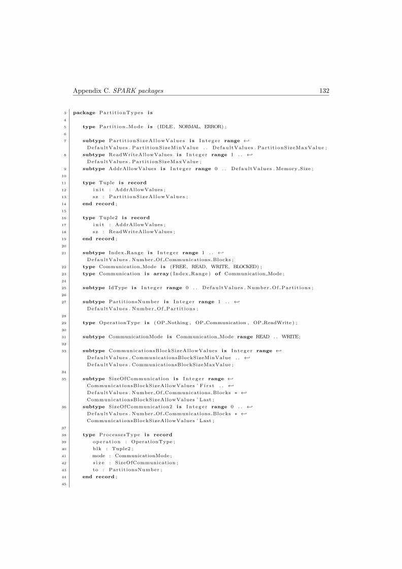
Appendix C. SPARK packages 132
3 package Part i t ionTypes i s
4
5 type Part it ion Mode i s (IDLE , NORMAL, ERROR) ;
6
7 subtype Part i t i onS i z eAl l owVa lues i s I n t eg e r range ←↩
DefaultValues . Part i t ionSizeMinValue . . DefaultValues . Part it ionSizeMaxValue ;
8 subtype ReadWriteAllowValues i s I n t eg e r range 1 . . ←↩
DefaultValues . Part it ionSizeMaxValue ;
9 subtype AddrAllowValues i s I n t eg e r range 0 . . DefaultValues . Memory Size ;
10
11 type Tuple i s record
12 i n i t : AddrAllowValues ;
13 sz : Par t i t i onS i zeA l l owVa lues ;
14 end record ;
15
16 type Tuple2 i s record
17 i n i t : AddrAllowValues ;
18 sz : ReadWriteAllowValues ;
19 end record ;
20
21 subtype Index Range i s I n t eg e r range 1 . . ←↩
DefaultValues . Number Of Communications Blocks ;
22 type Communication Mode i s (FREE, READ, WRITE, BLOCKED) ;
23 type Communication i s array ( Index Range ) of Communication Mode ;
24
25 subtype IdType i s I n t eg e r range 0 . . DefaultValues . Number Of Part it ions ;
26
27 subtype Partit ionsNumber i s I n t eg e r range 1 . . ←↩
DefaultValues . Number Of Part it ions ;
28
29 type OperationType i s ( OP Nothing , OP Communication , OP ReadWrite ) ;
30
31 subtype CommunicationMode i s Communication Mode range READ . . WRITE;
32
33 subtype CommunicationsBlockSizeAllowValues i s I n t eg e r range ←↩
DefaultValues . CommunicationsBlockSizeMinValue . . ←↩
DefaultValues . CommunicationsBlockSizeMaxValue ;
34
35 subtype SizeOfCommunication i s I n t eg e r range ←↩
CommunicationsBlockSizeAllowValues ’ F i r s t . . ←↩
DefaultValues . Number Of Communications Blocks ∗ ←↩
CommunicationsBlockSizeAllowValues ’ Last ;
36 subtype SizeOfCommunication2 i s I n t eg e r range 0 . . ←↩
DefaultValues . Number Of Communications Blocks ∗ ←↩
CommunicationsBlockSizeAllowValues ’ Last ;
37
38 type ProcessesType i s record
39 operat ion : OperationType ;
40 blk : Tuple2 ;
41 mode : CommunicationMode ;
42 s i z e : SizeOfCommunication ;
43 to : Partit ionsNumber ;
44 end record ;
45
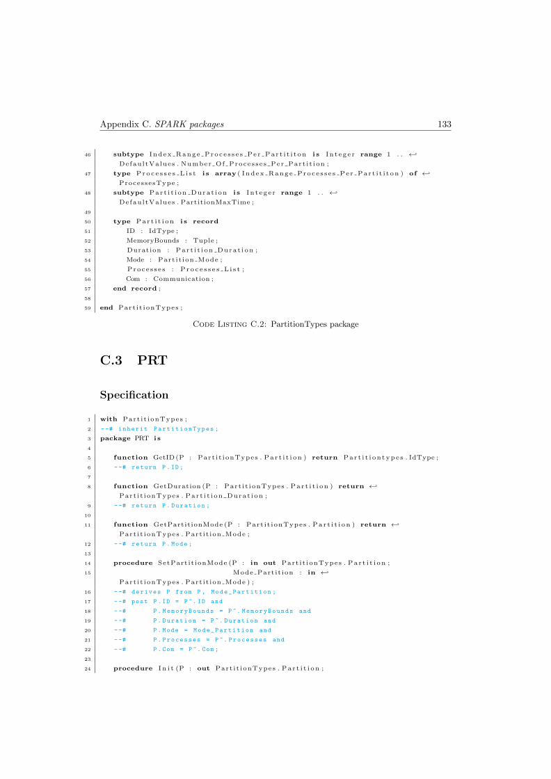
Appendix C. SPARK packages 133
46 subtype Index Range Proce s s e s Pe r Par t i t i t on i s I n t eg e r range 1 . . ←↩
DefaultValues . Number Of Processes Per Part i t ion ;
47 type P r o c e s s e s L i s t i s array ( Index Range Proce s s e s Pe r Par t i t i t on ) of ←↩
ProcessesType ;
48 subtype Par t i t i on Dura t i on i s I n t eg e r range 1 . . ←↩
DefaultValues . PartitionMaxTime ;
49
50 type P a r t i t i o n i s record
51 ID : IdType ;
52 MemoryBounds : Tuple ;
53 Duration : Par t i t i on Dura t i on ;
54 Mode : Part it ion Mode ;
55 Proce s s e s : P r o c e s s e s L i s t ;
56 Com : Communication ;
57 end record ;
58
59 end Part i t ionTypes ;
Code Listing C.2: PartitionTypes package
C.3 PRT
Specification
1 with Part i t ionTypes ;
2 --# inherit PartitionTypes ;
3 package PRT i s
4
5 function GetID (P : Part i t ionTypes . P a r t i t i o n ) return Par t i t i on type s . IdType ;
6 --# return P. ID ;
7
8 function GetDuration (P : Part i t ionTypes . P a r t i t i o n ) return ←↩
Part i t ionTypes . Par t i t i on Dura t i on ;
9 --# return P. Duration ;
10
11 function GetPartitionMode (P : Part i t ionTypes . P a r t i t i o n ) return ←↩
Part i t ionTypes . Part it ion Mode ;
12 --# return P. Mode ;
13
14 procedure SetPart it ionMode (P : in out Part i t ionTypes . P a r t i t i o n ;
15 Mode Part it ion : in ←↩
Part i t ionTypes . Part it ion Mode ) ;
16 --# derives P from P , Mode_Partition ;
17 --# post P. ID = P ~. ID and
18 --# P. MemoryBounds = P ~. MemoryBounds and
19 --# P. Duration = P ~. Duration and
20 --# P. Mode = Mode_Partition and
21 --# P. Processes = P ~. Processes and
22 --# P. Com = P ~. Com ;
23
24 procedure I n i t (P : out Part i t ionTypes . P a r t i t i o n ;
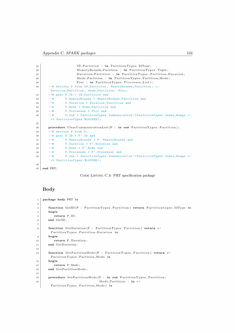
Appendix C. SPARK packages 134
25 ID Par t i t i on : in Part i t ionTypes . IdType ;
26 MemoryBounds Partition : in Part i t ionTypes . Tuple ;
27 Durat i on Par t i t i on : in Part i t ionTypes . Par t i t i on Dura t i on ;
28 Mode Part it ion : in Part i t ionTypes . Part it ion Mode ;
29 Proc : in Part i t ionTypes . P r o c e s s e s L i s t ) ;
30 --# derives P from ID_Partition , MemoryBounds_Partition , ←↩
Duration_Partition , Mode_Partition , Proc ;
31 --# post P. ID = ID_Partition and
32 --# P. MemoryBounds = MemoryBounds_Partition and
33 --# P. Duration = Duration_Partition and
34 --# P. Mode = Mode_Partition and
35 --# P. Processes = Proc and
36 --# P. Com = PartitionTypes . Communication ’( PartitionTypes . Index_Range ←↩
=> PartitionTypes . BLOCKED );
37
38 procedure ClearCommunicationList (P : in out Part i t ionTypes . P a r t i t i o n ) ;
39 --# derives P from P;
40 --# post P. ID = P ~. ID and
41 --# P. MemoryBounds = P ~. MemoryBounds and
42 --# P. Duration = P ~. Duration and
43 --# P. Mode = P ~. Mode and
44 --# P. Processes = P ~. Processes and
45 --# P. Com = PartitionTypes . Communication ’( PartitionTypes . Index_Range ←↩
=> PartitionTypes . BLOCKED );
46
47 end PRT;
Code Listing C.3: PRT specification package
Body
1 package body PRT i s
2
3 function GetID (P : Part i t ionTypes . P a r t i t i o n ) return Par t i t i on type s . IdType i s
4 begin
5 return P. ID ;
6 end GetID ;
7
8 function GetDuration (P : Part i t ionTypes . P a r t i t i o n ) return ←↩
Part i t ionTypes . Par t i t i on Dura t i on i s
9 begin
10 return P. Duration ;
11 end GetDuration ;
12
13 function GetPartitionMode (P : Part i t ionTypes . P a r t i t i o n ) return ←↩
Part i t ionTypes . Part it ion Mode i s
14 begin
15 return P. Mode ;
16 end GetPartitionMode ;
17
18 procedure SetPart it ionMode (P : in out Part i t ionTypes . P a r t i t i o n ;
19 Mode Part it ion : in ←↩
Part i t ionTypes . Part it ion Mode ) i s
Appendix C. SPARK packages 135
20 begin
21 P. ID := P. ID ;
22 P. MemoryBounds := P. MemoryBounds ;
23 P. Duration := P. Duration ;
24 P. Mode := Mode Part it ion ;
25 P.Com := P.Com;
26 P. Proce s s e s := P. Proce s s e s ;
27 end SetPart it ionMode ;
28
29 procedure I n i t (P : out Part i t ionTypes . P a r t i t i o n ;
30 ID Par t i t i on : in Part i t ionTypes . IdType ;
31 MemoryBounds Partition : in Part i t ionTypes . Tuple ;
32 Durat i on Par t i t i on : in Part i t ionTypes . Par t i t i on Dura t i on ;
33 Mode Part it ion : in Part i t ionTypes . Part it ion Mode ;
34 Proc : in Part i t ionTypes . P r o c e s s e s L i s t ) i s
35 begin
36 P. ID := ID Par t i t i on ;
37 P. MemoryBounds := MemoryBounds Partition ;
38 P. Duration := Durat i on Par t i t i on ;
39 P. Mode := Mode Part it ion ;
40 P. Proce s s e s := Proc ;
41 P.Com := Part i t ionTypes . Communication ’ ( Part i t ionTypes . Index Range => ←↩
Part i t ionTypes .BLOCKED) ;
42 end I n i t ;
43
44 procedure ClearCommunicationList (P : in out Part i t ionTypes . P a r t i t i o n ) i s
45 begin
46 P. ID := P. ID ;
47 P. MemoryBounds := P. MemoryBounds ;
48 P. Duration := P. Duration ;
49 P. Mode := P. Mode ;
50 P.Com := Part i t ionTypes . Communication ’ ( Part i t ionTypes . Index Range => ←↩
Part i t ionTypes .BLOCKED) ;
51 end ClearCommunicationList ;
52
53 end PRT;
Code Listing C.4: PRT body package
C.4 TablesTypes
1 with DefaultValues , Part i t ionTypes ;
2 --# inherit DefaultValues , PartitionTypes ;
3 package TablesTypes i s
4
5 type Par t i t i on sTab l e i s array ( Part i t ionTypes . Partit ionsNumber ) of ←↩
Part i t ionTypes . P a r t i t i o n ;
6
7 type Blocks Sta te i s (FREE, OCCUPIED) ;
8
9 type TupleCommunication i s record
10 i n i t : Part i t ionTypes . AddrAllowValues ;
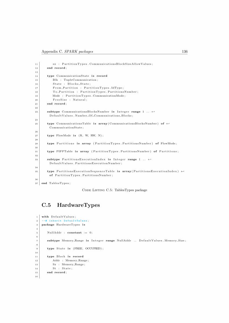
Appendix C. SPARK packages 136
11 sz : Part i t ionTypes . CommunicationsBlockSizeAllowValues ;
12 end record ;
13
14 type CommunicationState i s record
15 Blk : TupleCommunication ;
16 State : B locks Sta te ;
17 From Part i t ion : Part i t ionTypes . IdType ;
18 To Part i t i on : Part i t ionTypes . Partit ionsNumber ;
19 Mode : Part i t ionTypes . CommunicationMode ;
20 FreeS i ze : Natural ;
21 end record ;
22
23 subtype CommunicationsBlocksNumber i s I n t eg e r range 1 . . ←↩
DefaultValues . Number Of Communications Blocks ;
24
25 type CommunicationsTable i s array ( CommunicationsBlocksNumber ) of ←↩
CommunicationState ;
26
27 type FlowMode i s (R, W, RW, N) ;
28
29 type P a r t i t i o n s i s array ( Part i t ionTypes . Partit ionsNumber ) of FlowMode ;
30
31 type PIFPTable i s array ( Part i t ionTypes . Partit ionsNumber ) of P a r t i t i o n s ;
32
33 subtype Part i t i onsExecut ionIndex i s I n t eg e r range 1 . . ←↩
DefaultValues . Partit ionsExecutionNumber ;
34
35 type Part i t ionsExecut ionSequenceTable i s array ( Par t i t i onsExecut ionIndex ) ←↩
of Part i t ionTypes . Partit ionsNumber ;
36
37 end TablesTypes ;
Code Listing C.5: TablesTypes package
C.5 HardwareTypes
1 with DefaultValues ;
2 --# inherit DefaultValues ;
3 package HardwareTypes i s
4
5 NullAddr : constant := 0 ;
6
7 subtype Memory Range i s I n t eg e r range NullAddr . . DefaultValues . Memory Size ;
8
9 type State i s (FREE, OCCUPIED) ;
10
11 type Block i s record
12 Addr : Memory Range ;
13 Sz : Memory Range ;
14 St : State ;
15 end record ;
16
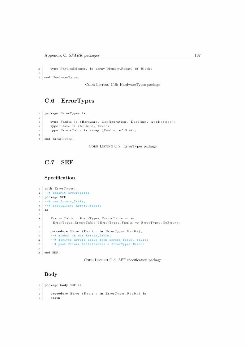
Appendix C. SPARK packages 137
17 type PhysicalMemory i s array ( Memory Range ) of Block ;
18
19 end HardwareTypes ;
Code Listing C.6: HardwareTypes package
C.6 ErrorTypes
1 package ErrorTypes i s
2
3 type Faults i s ( Hardware , Conf igurat ion , Deadline , Appl i cat ion ) ;
4 type State i s ( NoError , Error ) ;
5 type ErrorsTable i s array ( Faults ) of State ;
6
7 end ErrorTypes ;
Code Listing C.7: ErrorTypes package
C.7 SEF
Specification
1 with ErrorTypes ;
2 --# inherit ErrorTypes ;
3 package SEF
4 --# own Errors_Table ;
5 --# initializes Errors_Table ;
6 i s
7
8 Errors Table : ErrorTypes . ErrorsTable := ←↩
ErrorTypes . ErrorsTable ’ ( ErrorTypes . Faults => ErrorTypes . NoError ) ;
9
10 procedure Error ( Fault : in ErrorTypes . Faults ) ;
11 --# global in out Errors_Table ;
12 --# derives Errors_Table from Errors_Table , Fault ;
13 --# post Errors_Table ( Fault ) = ErrorTypes . Error ;
14
15 end SEF ;
Code Listing C.8: SEF specification package
Body
1 package body SEF i s
2
3 procedure Error ( Fault : in ErrorTypes . Faults ) i s
4 begin
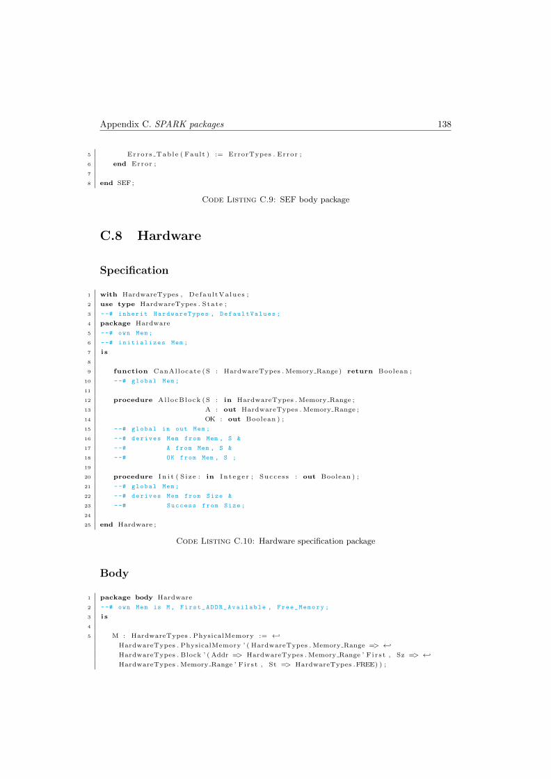
Appendix C. SPARK packages 138
5 Errors Table ( Fault ) := ErrorTypes . Error ;
6 end Error ;
7
8 end SEF ;
Code Listing C.9: SEF body package
C.8 Hardware
Specification
1 with HardwareTypes , DefaultValues ;
2 use type HardwareTypes . State ;
3 --# inherit HardwareTypes , DefaultValues ;
4 package Hardware
5 --# own Mem ;
6 --# initializes Mem ;
7 i s
8
9 function CanAllocate (S : HardwareTypes . Memory Range ) return Boolean ;
10 --# global Mem ;
11
12 procedure AllocBlock (S : in HardwareTypes . Memory Range ;
13 A : out HardwareTypes . Memory Range ;
14 OK : out Boolean ) ;
15 --# global in out Mem ;
16 --# derives Mem from Mem , S &
17 --# A from Mem , S &
18 --# OK from Mem , S ;
19
20 procedure I n i t ( S i z e : in I n t eg e r ; Success : out Boolean ) ;
21 --# global Mem ;
22 --# derives Mem from Size &
23 --# Success from Size ;
24
25 end Hardware ;
Code Listing C.10: Hardware specification package
Body
1 package body Hardware
2 --# own Mem is M , First_ADDR_Available , Free_Memory ;
3 i s
4
5 M : HardwareTypes . PhysicalMemory := ←↩
HardwareTypes . PhysicalMemory ’ ( HardwareTypes . Memory Range => ←↩
HardwareTypes . Block ’ ( Addr => HardwareTypes . Memory Range ’ F i r s t , Sz => ←↩
HardwareTypes . Memory Range ’ F i r s t , St => HardwareTypes .FREE) ) ;
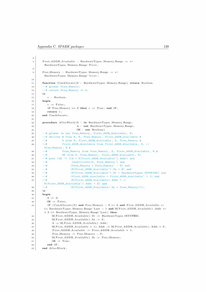
Appendix C. SPARK packages 139
6
7 First ADDR Available : HardwareTypes . Memory Range := ←↩
HardwareTypes . Memory Range ’ F i r s t ;
8
9 Free Memory : HardwareTypes . Memory Range := ←↩
HardwareTypes . Memory Range ’ f i r s t ;
10
11 function CanAllocate (S : HardwareTypes . Memory Range ) return Boolean
12 --# global Free_Memory ;
13 --# return Free_Memory >= S;
14 i s
15 r : Boolean ;
16 begin
17 r := False ;
18 i f Free Memory >= S then r := True ; end i f ;
19 return r ;
20 end CanAllocate ;
21
22 procedure AllocBlock (S : in HardwareTypes . Memory Range ;
23 A : out HardwareTypes . Memory Range ;
24 OK : out Boolean )
25 --# global in out Free_Memory , First_ADDR_Available , M;
26 --# derives M from M , S , Free_Memory , First_ADDR_Available &
27 --# A from M , First_ADDR_Available , S , Free_Memory &
28 --# First_ADDR_Available from First_ADDR_Available , S , ←↩
Free_Memory , M &
29 --# Free_Memory from Free_Memory , S , First_ADDR_Available , M &
30 --# OK from S , Free_Memory , First_ADDR_Available , M;
31 --# post ( OK -> (( A = M( First_ADDR_Available ~) . Addr ) and
32 --# CanAllocate (S , Free_Memory ~) and
33 --# ( Free_Memory = Free_Memory ~ - S) and
34 --# (M( First_ADDR_Available ~) . Sz = S) and
35 --# (M( First_ADDR_Available ~) . St = HardwareTypes . OCCUPIED ) and
36 --# ( First_ADDR_Available = First_ADDR_Available ~ + 1) and
37 --# (M( First_ADDR_Available ). Addr = ←↩
M( First_ADDR_Available ~) . Addr + S) and
38 --# (M( First_ADDR_Available ). Sz = Free_Memory )));
39 i s
40 begin
41 A := 0 ;
42 OK := False ;
43 i f ( CanAllocate (S) and Free Memory − S >= 0 and First ADDR Available ←↩
<= HardwareTypes . Memory Range ’ Last − 1 and M( First ADDR Available ) . Addr ←↩
+ S <= HardwareTypes . Memory Range ’ Last ) then
44 M( First ADDR Available ) . St := HardwareTypes .OCCUPIED;
45 M( First ADDR Available ) . Sz := S ;
46 A := M( First ADDR Available ) . Addr ;
47 M( First ADDR Available + 1) . Addr := M( First ADDR Available ) . Addr + S ;
48 First ADDR Available := First ADDR Available + 1 ;
49 Free Memory := Free Memory − S ;
50 M( First ADDR Available ) . Sz := Free Memory ;
51 OK := True ;
52 end i f ;
53 end AllocBlock ;
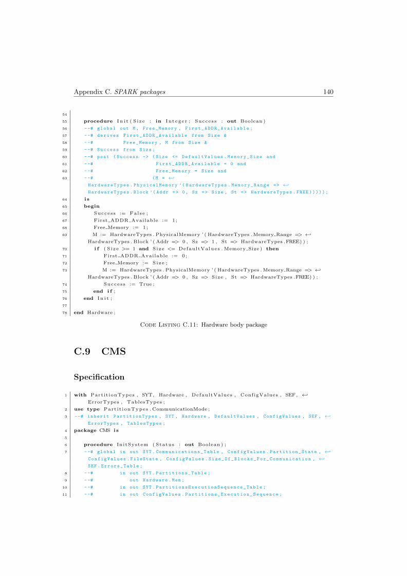
Appendix C. SPARK packages 140
54
55 procedure I n i t ( S i z e : in I n t eg e r ; Success : out Boolean )
56 --# global out M , Free_Memory , First_ADDR_Available ;
57 --# derives First_ADDR_Available from Size &
58 --# Free_Memory , M from Size &
59 --# Success from Size ;
60 --# post ( Success -> ( Size <= DefaultValues . Memory_Size and
61 --# First_ADDR_Available = 0 and
62 --# Free_Memory = Size and
63 --# (M = ←↩
HardwareTypes . PhysicalMemory ’( HardwareTypes . Memory_Range => ←↩
HardwareTypes . Block ’( Addr => 0, Sz => Size , St => HardwareTypes . FREE )))));
64 i s
65 begin
66 Success := False ;
67 First ADDR Available := 1 ;
68 Free Memory := 1 ;
69 M := HardwareTypes . PhysicalMemory ’ ( HardwareTypes . Memory Range => ←↩
HardwareTypes . Block ’ ( Addr => 0 , Sz => 1 , St => HardwareTypes .FREE) ) ;
70 i f ( S i z e >= 1 and S i z e <= DefaultValues . Memory Size ) then
71 First ADDR Available := 0 ;
72 Free Memory := S i z e ;
73 M := HardwareTypes . PhysicalMemory ’ ( HardwareTypes . Memory Range => ←↩
HardwareTypes . Block ’ ( Addr => 0 , Sz => Size , St => HardwareTypes .FREE) ) ;
74 Success := True ;
75 end i f ;
76 end I n i t ;
77
78 end Hardware ;
Code Listing C.11: Hardware body package
C.9 CMS
Specification
1 with Part it ionTypes , SYT, Hardware , DefaultValues , ConfigValues , SEF, ←↩
ErrorTypes , TablesTypes ;
2 use type Part i t ionTypes . CommunicationMode ;
3 --# inherit PartitionTypes , SYT , Hardware , DefaultValues , ConfigValues , SEF , ←↩
ErrorTypes , TablesTypes ;
4 package CMS i s
5
6 procedure In i tSystem ( Status : out Boolean ) ;
7 --# global in out SYT . Communications_Table , ConfigValues . Partition_State , ←↩
ConfigValues . FileState , ConfigValues . Size_Of_Blocks_For_Communication , ←↩
SEF . Errors_Table ;
8 --# in out SYT . Partitions_Table ;
9 --# out Hardware . Mem ;
10 --# in out SYT . PartitionsExecutionSequence_Table ;
11 --# in out ConfigValues . Partitions_Execution_Sequence ;
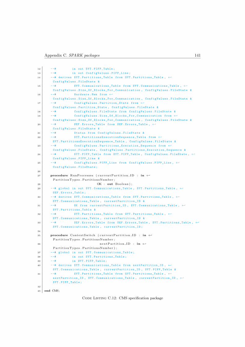
Appendix C. SPARK packages 141
12 --# in out SYT . PIFP_Table ;
13 --# in out ConfigValues . PIFP_Line ;
14 --# derives SYT . Partitions_Table from SYT . Partitions_Table , ←↩
ConfigValues . FileState &
15 --# SYT . Communications_Table from SYT . Communications_Table , ←↩
ConfigValues . Size_Of_Blocks_For_Communication , ConfigValues . FileState &
16 --# Hardware . Mem from ←↩
ConfigValues . Size_Of_Blocks_For_Communication , ConfigValues . FileState &
17 --# ConfigValues . Partition_State from ←↩
ConfigValues . Partition_State , ConfigValues . FileState &
18 --# ConfigValues . FileState from ConfigValues . FileState &
19 --# ConfigValues . Size_Of_Blocks_For_Communication from ←↩
ConfigValues . Size_Of_Blocks_For_Communication , ConfigValues . FileState &
20 --# SEF . Errors_Table from SEF . Errors_Table , ←↩
ConfigValues . FileState &
21 --# Status from ConfigValues . FileState &
22 --# SYT . PartitionsExecutionSequence_Table from ←↩
SYT . PartitionsExecutionSequence_Table , ConfigValues . FileState &
23 --# ConfigValues . Partitions_Execution_Sequence from ←↩
ConfigValues . FileState , ConfigValues . Partitions_Execution_Sequence &
24 --# SYT . PIFP_Table from SYT . PIFP_Table , ConfigValues . FileState , ←↩
ConfigValues . PIFP_Line &
25 --# ConfigValues . PIFP_Line from ConfigValues . PIFP_Line , ←↩
ConfigValues . FileState ;
26
27 procedure RunProcesses ( cu r r en tPa r t i t i on ID : in ←↩
Part i t ionTypes . Partit ionsNumber ;
28 OK : out Boolean ) ;
29 --# global in out SYT . Communications_Table , SYT . Partitions_Table , ←↩
SEF . Errors_Table ;
30 --# derives SYT . Communications_Table from SYT . Partitions_Table , ←↩
SYT . Communications_Table , currentPartition_ID &
31 --# OK from currentPartition_ID , SYT . Communications_Table , ←↩
SYT . Partitions_Table &
32 --# SYT . Partitions_Table from SYT . Partitions_Table , ←↩
SYT . Communications_Table , currentPartition_ID &
33 --# SEF . Errors_Table from SEF . Errors_Table , SYT . Partitions_Table , ←↩
SYT . Communications_Table , currentPartition_ID ;
34
35 procedure ContextSwitch ( cu r r en tPa r t i t i on ID : in ←↩
Part i t ionTypes . Partit ionsNumber ;
36 nextPar t i t i on ID : in ←↩
Part i t ionTypes . Partit ionsNumber ) ;
37 --# global in out SYT . Communications_Table ;
38 --# in out SYT . Partitions_Table ;
39 --# in SYT . PIFP_Table ;
40 --# derives SYT . Communications_Table from nextPartition_ID , ←↩
SYT . Communications_Table , currentPartition_ID , SYT . PIFP_Table &
41 --# SYT . Partitions_Table from SYT . Partitions_Table , ←↩
nextPartition_ID , SYT . Communications_Table , currentPartition_ID , ←↩
SYT . PIFP_Table ;
42
43 end CMS;
Code Listing C.12: CMS specification package
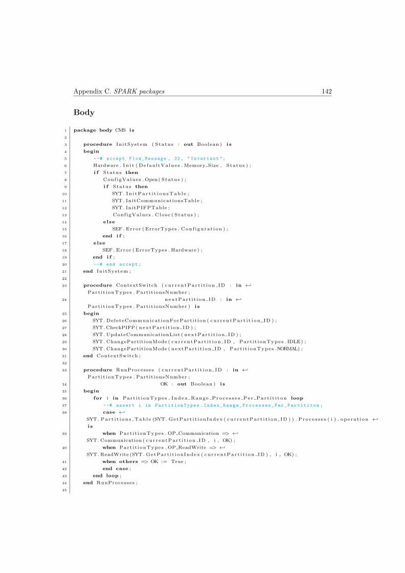
Appendix C. SPARK packages 142
Body
1 package body CMS i s
2
3 procedure In i tSystem ( Status : out Boolean ) i s
4 begin
5 --# accept Flow_Message , 22 , " Invariant ";
6 Hardware . I n i t ( DefaultValues . Memory Size , Status ) ;
7 i f Status then
8 ConfigValues . Open( Status ) ;
9 i f Status then
10 SYT. I n i t P a r t i t i o n s T a b l e ;
11 SYT. InitCommunicationsTable ;
12 SYT. InitPIFPTable ;
13 ConfigValues . Close ( Status ) ;
14 else
15 SEF . Error ( ErrorTypes . Conf igurat ion ) ;
16 end i f ;
17 else
18 SEF . Error ( ErrorTypes . Hardware ) ;
19 end i f ;
20 --# end accept ;
21 end In i tSystem ;
22
23 procedure ContextSwitch ( cu r r en tPa r t i t i on ID : in ←↩
Part i t ionTypes . Partit ionsNumber ;
24 nextPar t i t i on ID : in ←↩
Part i t ionTypes . Partit ionsNumber ) i s
25 begin
26 SYT. DeleteCommunicationForPartit ion ( cu r r en tPa r t i t i on ID ) ;
27 SYT. CheckPIFP( nextPar t i t i on ID ) ;
28 SYT. UpdateCommunicationList ( nextPar t i t i on ID ) ;
29 SYT. ChangePartitionMode ( cur r entPar t i t i on ID , Part i t ionTypes . IDLE) ;
30 SYT. ChangePartitionMode ( nextPart i t ion ID , Part i t ionTypes .NORMAL) ;
31 end ContextSwitch ;
32
33 procedure RunProcesses ( cu r r en tPa r t i t i on ID : in ←↩
Part i t ionTypes . Partit ionsNumber ;
34 OK : out Boolean ) i s
35 begin
36 for i in Part i t ionTypes . Index Range Proce s s e s Pe r Par t i t i t on loop
37 --# assert i in PartitionTypes . Index_Range_Processes_Per_Partititon ;
38 case ←↩
SYT. Par t i t i on s Tab l e (SYT. GetPart i t ionIndex ( cu r r en tPa r t i t i on ID ) ) . Proce s s e s ( i ) . operat ion ←↩
i s
39 when Part i t ionTypes . OP Communication => ←↩
SYT. Communication ( cur r entPar t i t i on ID , i , OK) ;
40 when Part i t ionTypes . OP ReadWrite => ←↩
SYT. ReadWrite (SYT. GetPart i t ionIndex ( cu r r en tPa r t i t i on ID ) , i , OK) ;
41 when others => OK := True ;
42 end case ;
43 end loop ;
44 end RunProcesses ;
45
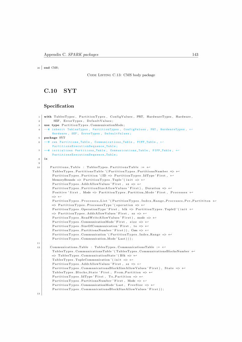
Appendix C. SPARK packages 143
46 end CMS;
Code Listing C.13: CMS body package
C.10 SYT
Specification
1 with TablesTypes , Part it ionTypes , ConfigValues , PRT, HardwareTypes , Hardware ,
2 SEF, ErrorTypes , DefaultValues ;
3 use type Part i t ionTypes . CommunicationMode ;
4 --# inherit TablesTypes , PartitionTypes , ConfigValues , PRT , HardwareTypes , ←↩
Hardware , SEF , ErrorTypes , DefaultValues ;
5 package SYT
6 --# own Partitions_Table , Communications_Table , PIFP_Table , ←↩
PartitionsExecutionSequence_Table ;
7 --# initializes Partitions_Table , Communications_Table , PIFP_Table , ←↩
PartitionsExecutionSequence_Table ;
8 i s
9
10 Par t i t i on s Tab l e : TablesTypes . Par t i t i on sTab l e := ←↩
TablesTypes . Part i t i onsTab le ’ ( Part i t ionTypes . Partit ionsNumber => ←↩
Part i t ionTypes . Par t i t i on ’ ( ID => Part i t ionTypes . IdType ’ F i r s t , ←↩
MemoryBounds => Part i t ionTypes . Tuple ’ ( i n i t => ←↩
Part i t ionTypes . AddrAllowValues ’ F i r s t , sz => ←↩
Part i t ionTypes . Part i t i onS izeAl lowValues ’ F i r s t ) , Duration => ←↩
Pos i t ive ’ f i r s t , Mode => Part i t ionTypes . Partit ion Mode ’ F i r s t , Proce s s e s ←↩
=> ←↩
Part i t ionTypes . P ro c e s s e s L i s t ’ ( Part i t ionTypes . Index Range Proce s s e s Pe r Par t i t i t on ←↩
=> Part i t ionTypes . ProcessesType ’ ( operat ion => ←↩
Part i t ionTypes . OperationType ’ F i r s t , blk => Part i t ionTypes . Tuple2 ’ ( i n i t ←↩
=> Part i t ionTypes . AddrAllowValues ’ F i r s t , sz => ←↩
Part i t ionTypes . ReadWriteAllowValues ’ F i r s t ) , mode => ←↩
Part i t ionTypes . CommunicationMode ’ F i r s t , s i z e => ←↩
Part i t ionTypes . SizeOfCommunication ’ F i r s t , to => ←↩
Part i t ionTypes . PartitionsNumber ’ F i r s t ) ) , Com => ←↩
Part i t ionTypes . Communication ’ ( Part i t ionTypes . Index Range => ←↩
Part i t ionTypes . Communication Mode ’ Last ) ) ) ;
11
12 Communications Table : TablesTypes . CommunicationsTable := ←↩
TablesTypes . CommunicationsTable ’ ( TablesTypes . CommunicationsBlocksNumber ←↩
=> TablesTypes . CommunicationState ’ ( Blk => ←↩
TablesTypes . TupleCommunication ’ ( i n i t => ←↩
Part i t ionTypes . AddrAllowValues ’ F i r s t , sz => ←↩
Part i t ionTypes . CommunicationsBlockSizeAllowValues ’ F i r s t ) , State => ←↩
TablesTypes . Blocks State ’ F i r s t , From Part i t ion => ←↩
Part i t ionTypes . IdType ’ F i r s t , To Part i t i on => ←↩
Part i t ionTypes . PartitionsNumber ’ F i r s t , Mode => ←↩
Part i t ionTypes . CommunicationMode ’ Last , FreeS i ze => ←↩
Part i t ionTypes . CommunicationsBlockSizeAllowValues ’ F i r s t ) ) ;
13

Appendix C. SPARK packages 144
14 PIFP Table : TablesTypes . PIFPTable := ←↩
TablesTypes . PIFPTable ’ ( Part i t ionTypes . Partit ionsNumber => ←↩
( TablesTypes . Par t i t i on s ’ ( Part i t ionTypes . Partit ionsNumber => ←↩
TablesTypes . FlowMode ’ Last ) ) ) ;
15
16 Part i t i onsExecut ionSequence Table : ←↩
TablesTypes . Part i t ionsExecut ionSequenceTable := ←↩
TablesTypes . Part i t ionsExecut ionSequenceTable ’ ( TablesTypes . Par t i t i onsExecut ionIndex ←↩
=> TablesTypes . Part i t ionsExecut ionIndex ’ F i r s t ) ;
17
18
19 procedure I n i t P a r t i t i o n s T a b l e ;
20 --# global out Partitions_Table ;
21 --# in out ConfigValues . Partition_State ;
22 --# in out Hardware . Mem ;
23 --# in out ConfigValues . FileState ;
24 --# in out ConfigValues . Size_Of_Blocks_For_Communication ;
25 --# in out SEF . Errors_Table ;
26 --# out PartitionsExecutionSequence_Table ;
27 --# in out ConfigValues . Partitions_Execution_Sequence ;
28 --# derives Partitions_Table from Hardware . Mem , ConfigValues . FileState &
29 --# Hardware . Mem from Hardware . Mem , ConfigValues . FileState &
30 --# ConfigValues . Partition_State from ←↩
ConfigValues . Partition_State , ConfigValues . FileState &
31 --# ConfigValues . FileState from ConfigValues . FileState &
32 --# SEF . Errors_Table from SEF . Errors_Table , ←↩
ConfigValues . FileState , Hardware . Mem &
33 --# PartitionsExecutionSequence_Table from ConfigValues . FileState &
34 --# ConfigValues . Partitions_Execution_Sequence from ←↩
ConfigValues . Partitions_Execution_Sequence , ConfigValues . FileState &
35 --# ConfigValues . Size_Of_Blocks_For_Communication from ←↩
ConfigValues . Size_Of_Blocks_For_Communication , ConfigValues . FileState ;
36
37 procedure InitCommunicationsTable ;
38 --# global in out Communications_Table ;
39 --# in out Hardware . Mem ;
40 --# in ConfigValues . Size_Of_Blocks_For_Communication ;
41 --# derives Communications_Table from Communications_Table , Hardware . Mem , ←↩
ConfigValues . Size_Of_Blocks_For_Communication &
42 --# Hardware . Mem from Hardware . Mem , ←↩
ConfigValues . Size_Of_Blocks_For_Communication ;
43
44 procedure InitPIFPTable ;
45 --# global in out PIFP_Table ;
46 --# in out ConfigValues . FileState ;
47 --# in out configValues . PIFP_Line ;
48 --# in out SEF . Errors_Table ;
49 --# derives configValues . PIFP_Line from configValues . PIFP_Line , ←↩
ConfigValues . FileState &
50 --# PIFP_Table from PIFP_Table , configValues . PIFP_Line , ←↩
ConfigValues . FileState &
51 --# ConfigValues . FileState from ConfigValues . FileState &
52 --# SEF . Errors_Table from SEF . Errors_Table , ConfigValues . FileState ;
53
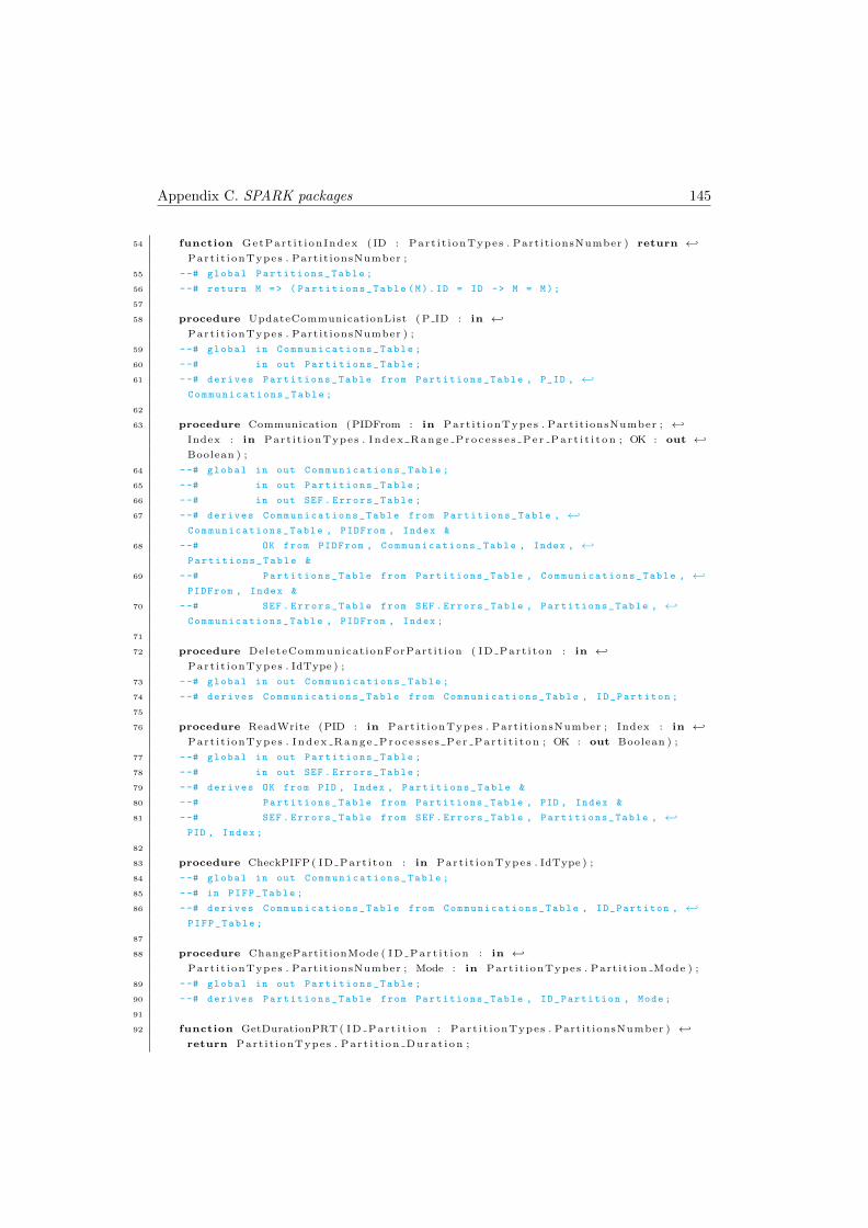
Appendix C. SPARK packages 145
54 function GetPart i t ionIndex ( ID : Part i t ionTypes . Partit ionsNumber ) return ←↩
Part i t ionTypes . Partit ionsNumber ;
55 --# global Partitions_Table ;
56 --# return M => ( Partitions_Table (M). ID = ID -> M = M);
57
58 procedure UpdateCommunicationList ( P ID : in ←↩
Part i t ionTypes . Partit ionsNumber ) ;
59 --# global in Communications_Table ;
60 --# in out Partitions_Table ;
61 --# derives Partitions_Table from Partitions_Table , P_ID , ←↩
Communications_Table ;
62
63 procedure Communication (PIDFrom : in Part i t ionTypes . Partit ionsNumber ; ←↩
Index : in Part i t ionTypes . Index Range Proce s s e s Pe r Par t i t i t on ; OK : out ←↩
Boolean ) ;
64 --# global in out Communications_Table ;
65 --# in out Partitions_Table ;
66 --# in out SEF . Errors_Table ;
67 --# derives Communications_Table from Partitions_Table , ←↩
Communications_Table , PIDFrom , Index &
68 --# OK from PIDFrom , Communications_Table , Index , ←↩
Partitions_Table &
69 --# Partitions_Table from Partitions_Table , Communications_Table , ←↩
PIDFrom , Index &
70 --# SEF . Errors_Table from SEF . Errors_Table , Partitions_Table , ←↩
Communications_Table , PIDFrom , Index ;
71
72 procedure DeleteCommunicationForPartit ion ( ID Part i ton : in ←↩
Part i t ionTypes . IdType ) ;
73 --# global in out Communications_Table ;
74 --# derives Communications_Table from Communications_Table , ID_Partiton ;
75
76 procedure ReadWrite (PID : in Part i t ionTypes . Partit ionsNumber ; Index : in ←↩
Part i t ionTypes . Index Range Proce s s e s Pe r Par t i t i t on ; OK : out Boolean ) ;
77 --# global in out Partitions_Table ;
78 --# in out SEF . Errors_Table ;
79 --# derives OK from PID , Index , Partitions_Table &
80 --# Partitions_Table from Partitions_Table , PID , Index &
81 --# SEF . Errors_Table from SEF . Errors_Table , Partitions_Table , ←↩
PID , Index ;
82
83 procedure CheckPIFP( ID Part i ton : in Part i t ionTypes . IdType ) ;
84 --# global in out Communications_Table ;
85 --# in PIFP_Table ;
86 --# derives Communications_Table from Communications_Table , ID_Partiton , ←↩
PIFP_Table ;
87
88 procedure ChangePartitionMode ( ID Par t i t i on : in ←↩
Part i t ionTypes . Partit ionsNumber ; Mode : in Part i t ionTypes . Part it ion Mode ) ;
89 --# global in out Partitions_Table ;
90 --# derives Partitions_Table from Partitions_Table , ID_Partition , Mode ;
91
92 function GetDurationPRT ( ID Par t i t i on : Part i t ionTypes . Partit ionsNumber ) ←↩
return Part i t ionTypes . Par t i t i on Dura t i on ;
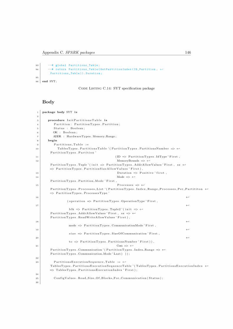
Appendix C. SPARK packages 146
93 --# global Partitions_Table ;
94 --# return Partitions_Table ( GetPartitionIndex ( ID_Partition , ←↩
Partitions_Table )). Duration ;
95
96 end SYT;
Code Listing C.14: SYT specification package
Body
1 package body SYT i s
2
3 procedure I n i t P a r t i t i o n s T a b l e i s
4 P a r t i t i o n : Part i t ionTypes . P a r t i t i o n ;
5 Status : Boolean ;
6 OK : Boolean ;
7 ADDR : HardwareTypes . Memory Range ;
8 begin
9 Par t i t i on s Tab l e :=
10 TablesTypes . Part i t i onsTab le ’ ( Part i t ionTypes . Partit ionsNumber => ←↩
Part i t ionTypes . Par t i t i on ’
11 ( ID => Part i t ionTypes . IdType ’ F i r s t ,
12 MemoryBounds => ←↩
Part i t ionTypes . Tuple ’ ( i n i t => Part i t ionTypes . AddrAllowValues ’ F i r s t , sz ←↩
=> Part i t ionTypes . Part i t i onS izeAl lowValues ’ F i r s t ) ,
13 Duration => Pos i t ive ’ f i r s t ,
14 Mode => ←↩
Part i t ionTypes . Partit ion Mode ’ F i r s t ,
15 Proce s s e s => ←↩
Part i t ionTypes . P ro c e s s e s L i s t ’ ( Part i t ionTypes . Index Range Proce s s e s Pe r Par t i t i t on ←↩
=> Part i t ionTypes . ProcessesType ’
16 ←↩
( operat ion => Part i t ionTypes . OperationType ’ F i r s t ,
17 ←↩
blk => Part i t ionTypes . Tuple2 ’ ( i n i t => ←↩
Part i t ionTypes . AddrAllowValues ’ F i r s t , sz => ←↩
Part i t ionTypes . ReadWriteAllowValues ’ F i r s t ) ,
18 ←↩
mode => Part i t ionTypes . CommunicationMode ’ F i r s t ,
19 ←↩
s i z e => Part i t ionTypes . SizeOfCommunication ’ F i r s t ,
20 ←↩
to => Part i t ionTypes . PartitionsNumber ’ F i r s t ) ) ,
21 Com => ←↩
Part i t ionTypes . Communication ’ ( Part i t ionTypes . Index Range => ←↩
Part i t ionTypes . Communication Mode ’ Last ) ) ) ;
22
23 Part i t i onsExecut ionSequence Table := ←↩
TablesTypes . Part i t ionsExecut ionSequenceTable ’ ( TablesTypes . Par t i t i onsExecut ionIndex ←↩
=> TablesTypes . Part i t ionsExecut ionIndex ’ F i r s t ) ;
24
25 ConfigValues . Read Size Of Blocks For Communication ( Status ) ;
26
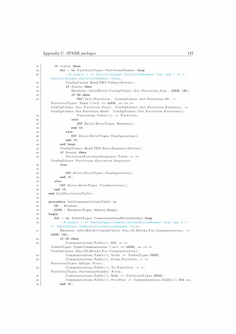
Appendix C. SPARK packages 147
27 i f s t a tu s then
28 for i in Part i t ionTypes . Partit ionsNumber loop
29 --# assert i <= PartitionTypes . PartitionsNumber ’ last and i >= ←↩
PartitionTypes . PartitionsNumber ’ first ;
30 ConfigValues . Read PRT Values ( Status ) ;
31 i f Status then
32 Hardware . Al locBlock ( Conf igValues . Ge t Pa r t i t i on S i z e , ADDR, OK) ;
33 i f OK then
34 PRT. I n i t ( Par t i t i on , Conf igValues . Get Part i t ion ID , ←↩
Part i t ionTypes . Tuple ’ ( i n i t => ADDR, sz => ←↩
ConfigValues . G e t P a r t i t i o n S i z e ) , Conf igValues . Get Part i t ion Durat ion , ←↩
ConfigValues . Get Partit ion Mode , Conf igValues . G e t Pa r t i t i on Pro c e s s e s ) ;
35 Par t i t i on s Tab l e ( i ) := P a r t i t i o n ;
36 else
37 SEF . Error ( ErrorTypes . Hardware ) ;
38 end i f ;
39 else
40 SEF . Error ( ErrorTypes . Conf igurat ion ) ;
41 end i f ;
42 end loop ;
43 ConfigValues . Read PRT Exec Sequence ( Status ) ;
44 i f Status then
45 Part i t i onsExecut ionSequence Table := ←↩
ConfigValues . Par t i t i ons Execut i on Sequence ;
46 else
47
48 SEF . Error ( ErrorTypes . Conf igurat ion ) ;
49 end i f ;
50 else
51 SEF . Error ( ErrorTypes . Conf igurat ion ) ;
52 end i f ;
53 end I n i t P a r t i t i o n s T a b l e ;
54
55 procedure InitCommunicationsTable i s
56 OK : Boolean ;
57 ADDR : HardwareTypes . Memory Range ;
58 begin
59 for i in TablesTypes . CommunicationsBlocksNumber loop
60 --# assert i <= TablesTypes . CommunicationsBlocksNumber ’ last and i ←↩
>= TablesTypes . CommunicationsBlocksNumber ’ first ;
61 Hardware . Al locBlock ( Conf igValues . Size Of Blocks For Communication , ←↩
ADDR, OK) ;
62 i f OK then
63 Communications Table ( i ) . Blk := ←↩
TablesTypes . TupleCommunication ’ ( i n i t => ADDR, sz => ←↩
ConfigValues . Size Of Blocks For Communicat ion ) ;
64 Communications Table ( i ) . State := TablesTypes .FREE;
65 Communications Table ( i ) . From Part i t ion := ←↩
Part i t ionTypes . IdType ’ F i r s t ;
66 Communications Table ( i ) . To Part i t i on := ←↩
Part i t ionTypes . PartitionsNumber ’ F i r s t ;
67 Communications Table ( i ) . Mode := Part i t ionTypes .READ;
68 Communications Table ( i ) . FreeS i ze := Communications Table ( i ) . Blk . sz ;
69 end i f ;
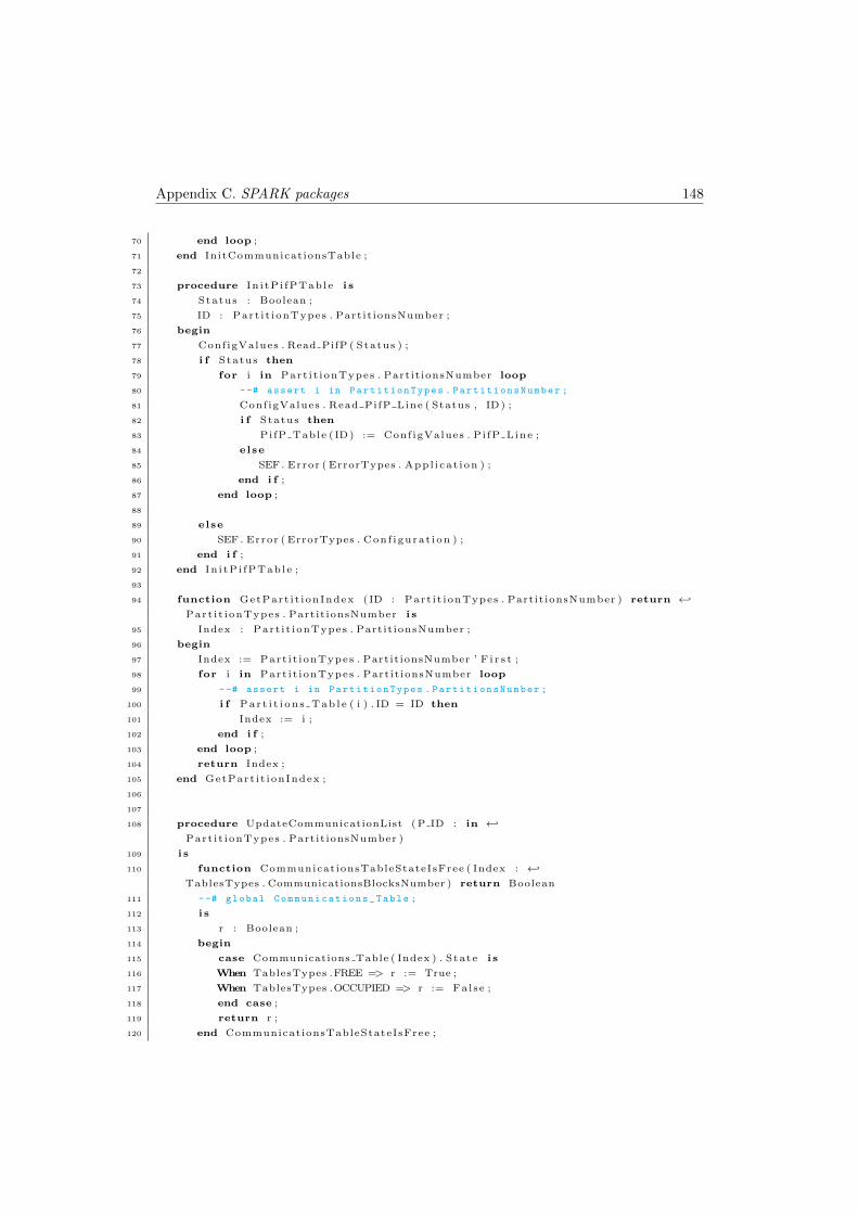
Appendix C. SPARK packages 148
70 end loop ;
71 end InitCommunicationsTable ;
72
73 procedure In i tP i fPTab le i s
74 Status : Boolean ;
75 ID : Part i t ionTypes . Partit ionsNumber ;
76 begin
77 ConfigValues . Read PifP ( Status ) ;
78 i f Status then
79 for i in Part i t ionTypes . Partit ionsNumber loop
80 --# assert i in PartitionTypes . PartitionsNumber ;
81 ConfigValues . Read PifP Line ( Status , ID) ;
82 i f Status then
83 PifP Table ( ID) := Conf igValues . Pi fP Line ;
84 else
85 SEF . Error ( ErrorTypes . Appl i cat ion ) ;
86 end i f ;
87 end loop ;
88
89 else
90 SEF . Error ( ErrorTypes . Conf igurat ion ) ;
91 end i f ;
92 end In i tP i fPTab le ;
93
94 function GetPart i t ionIndex ( ID : Part i t ionTypes . Partit ionsNumber ) return ←↩
Part i t ionTypes . Partit ionsNumber i s
95 Index : Part i t ionTypes . Partit ionsNumber ;
96 begin
97 Index := Part i t ionTypes . PartitionsNumber ’ F i r s t ;
98 for i in Part i t ionTypes . Partit ionsNumber loop
99 --# assert i in PartitionTypes . PartitionsNumber ;
100 i f Par t i t i on s Tab l e ( i ) . ID = ID then
101 Index := i ;
102 end i f ;
103 end loop ;
104 return Index ;
105 end GetPart i t ionIndex ;
106
107
108 procedure UpdateCommunicationList ( P ID : in ←↩
Part i t ionTypes . Partit ionsNumber )
109 i s
110 function CommunicationsTableStateIsFree ( Index : ←↩
TablesTypes . CommunicationsBlocksNumber ) return Boolean
111 --# global Communications_Table ;
112 i s
113 r : Boolean ;
114 begin
115 case Communications Table ( Index ) . State i s
116 When TablesTypes .FREE => r := True ;
117 When TablesTypes .OCCUPIED => r := False ;
118 end case ;
119 return r ;
120 end CommunicationsTableStateIsFree ;
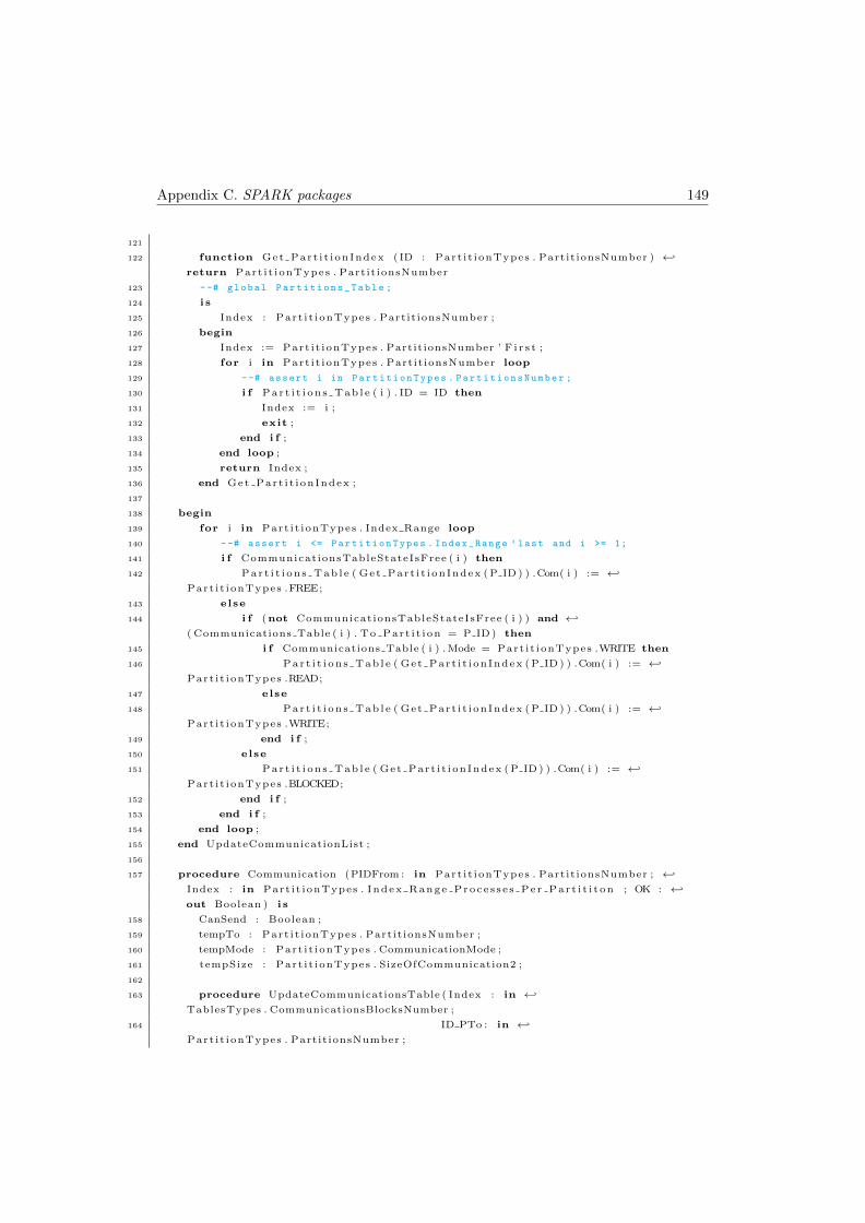
Appendix C. SPARK packages 149
121
122 function Get Part i t i onIndex ( ID : Part i t ionTypes . Partit ionsNumber ) ←↩
return Part i t ionTypes . Partit ionsNumber
123 --# global Partitions_Table ;
124 i s
125 Index : Part i t ionTypes . Partit ionsNumber ;
126 begin
127 Index := Part i t ionTypes . PartitionsNumber ’ F i r s t ;
128 for i in Part i t ionTypes . Partit ionsNumber loop
129 --# assert i in PartitionTypes . PartitionsNumber ;
130 i f Par t i t i on s Tab l e ( i ) . ID = ID then
131 Index := i ;
132 exit ;
133 end i f ;
134 end loop ;
135 return Index ;
136 end Get Part i t i onIndex ;
137
138 begin
139 for i in Part i t ionTypes . Index Range loop
140 --# assert i <= PartitionTypes . Index_Range ’ last and i >= 1;
141 i f CommunicationsTableStateIsFree ( i ) then
142 Par t i t i on s Tab l e ( Get Part i t i onIndex ( P ID ) ) .Com( i ) := ←↩
Part i t ionTypes .FREE;
143 else
144 i f (not CommunicationsTableStateIsFree ( i ) ) and ←↩
( Communications Table ( i ) . To Part i t i on = P ID ) then
145 i f Communications Table ( i ) . Mode = Part i t ionTypes .WRITE then
146 Par t i t i on s Tab l e ( Get Part i t i onIndex ( P ID ) ) .Com( i ) := ←↩
Part i t ionTypes .READ;
147 else
148 Par t i t i on s Tab l e ( Get Part i t i onIndex ( P ID ) ) .Com( i ) := ←↩
Part i t ionTypes .WRITE;
149 end i f ;
150 else
151 Par t i t i on s Tab l e ( Get Part i t i onIndex ( P ID ) ) .Com( i ) := ←↩
Part i t ionTypes .BLOCKED;
152 end i f ;
153 end i f ;
154 end loop ;
155 end UpdateCommunicationList ;
156
157 procedure Communication (PIDFrom : in Part i t ionTypes . Partit ionsNumber ; ←↩
Index : in Part i t ionTypes . Index Range Proce s s e s Pe r Par t i t i t on ; OK : ←↩
out Boolean ) i s
158 CanSend : Boolean ;
159 tempTo : Part i t ionTypes . Partit ionsNumber ;
160 tempMode : Part i t ionTypes . CommunicationMode ;
161 tempSize : Part i t ionTypes . SizeOfCommunication2 ;
162
163 procedure UpdateCommunicationsTable ( Index : in ←↩
TablesTypes . CommunicationsBlocksNumber ;
164 ID PTo : in ←↩
Part i t ionTypes . Partit ionsNumber ;
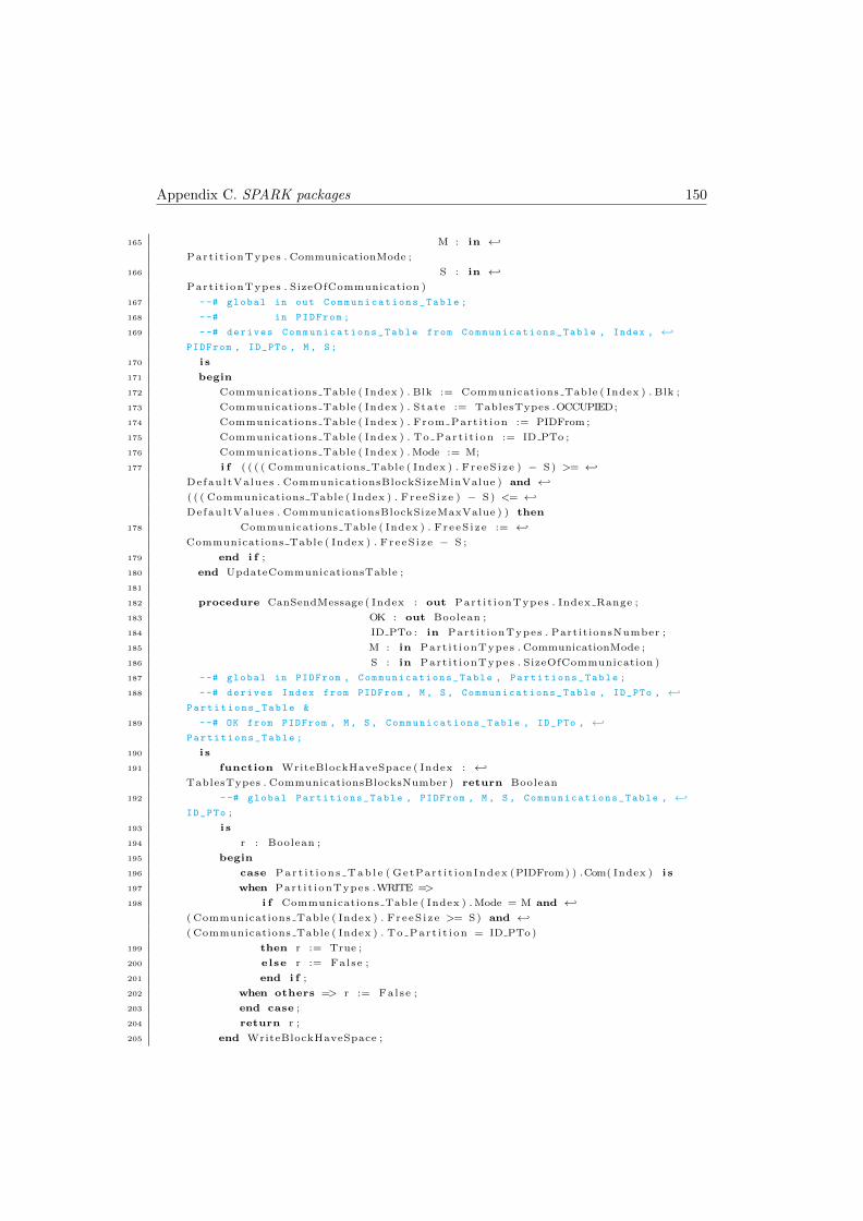
Appendix C. SPARK packages 150
165 M : in ←↩
Part i t ionTypes . CommunicationMode ;
166 S : in ←↩
Part i t ionTypes . SizeOfCommunication )
167 --# global in out Communications_Table ;
168 --# in PIDFrom ;
169 --# derives Communications_Table from Communications_Table , Index , ←↩
PIDFrom , ID_PTo , M , S;
170 i s
171 begin
172 Communications Table ( Index ) . Blk := Communications Table ( Index ) . Blk ;
173 Communications Table ( Index ) . State := TablesTypes .OCCUPIED;
174 Communications Table ( Index ) . From Part i t ion := PIDFrom ;
175 Communications Table ( Index ) . To Part i t i on := ID PTo ;
176 Communications Table ( Index ) . Mode := M;
177 i f ( ( ( ( Communications Table ( Index ) . FreeS i ze ) − S) >= ←↩
DefaultValues . CommunicationsBlockSizeMinValue ) and ←↩
( ( ( Communications Table ( Index ) . FreeS i ze ) − S) <= ←↩
DefaultValues . CommunicationsBlockSizeMaxValue ) ) then
178 Communications Table ( Index ) . FreeS i ze := ←↩
Communications Table ( Index ) . FreeS i ze − S ;
179 end i f ;
180 end UpdateCommunicationsTable ;
181
182 procedure CanSendMessage ( Index : out Part i t ionTypes . Index Range ;
183 OK : out Boolean ;
184 ID PTo : in Part i t ionTypes . Partit ionsNumber ;
185 M : in Part i t ionTypes . CommunicationMode ;
186 S : in Part i t ionTypes . SizeOfCommunication )
187 --# global in PIDFrom , Communications_Table , Partitions_Table ;
188 --# derives Index from PIDFrom , M , S , Communications_Table , ID_PTo , ←↩
Partitions_Table &
189 --# OK from PIDFrom , M , S , Communications_Table , ID_PTo , ←↩
Partitions_Table ;
190 i s
191 function WriteBlockHaveSpace ( Index : ←↩
TablesTypes . CommunicationsBlocksNumber ) return Boolean
192 --# global Partitions_Table , PIDFrom , M , S , Communications_Table , ←↩
ID_PTo ;
193 i s
194 r : Boolean ;
195 begin
196 case Par t i t i on s Tab l e ( GetPart i t ionIndex (PIDFrom) ) .Com( Index ) i s
197 when Part i t ionTypes .WRITE =>
198 i f Communications Table ( Index ) . Mode = M and ←↩
( Communications Table ( Index ) . FreeS i ze >= S) and ←↩
( Communications Table ( Index ) . To Part i t i on = ID PTo)
199 then r := True ;
200 else r := False ;
201 end i f ;
202 when others => r := False ;
203 end case ;
204 return r ;
205 end WriteBlockHaveSpace ;

Appendix C. SPARK packages 151
206
207 function BlockIsFree ( Index : ←↩
TablesTypes . CommunicationsBlocksNumber ) return Boolean
208 --# global PIDFrom , Partitions_Table ;
209 i s
210 r : Boolean ;
211 begin
212 case Par t i t i on s Tab l e ( GetPart i t ionIndex (PIDFrom) ) .Com( Index ) i s
213 when Part i t ionTypes .FREE => r := True ;
214 when others => r := False ;
215 end case ;
216 return r ;
217 end BlockIsFree ;
218
219 begin
220 OK := False ;
221 Index := 1 ;
222 for i in Part i t ionTypes . Index Range loop
223 --# assert i <= PartitionTypes . Index_Range ’ last and i >= 1;
224 i f WriteBlockHaveSpace ( i ) then
225 OK := True ;
226 Index := i ;
227 exit ;
228 end i f ;
229 i f BlockIsFree ( i ) then
230 OK := True ;
231 Index := i ;
232 exit ;
233 end i f ;
234 end loop ;
235 end CanSendMessage ;
236
237 procedure SendMessageSpl it (OK : out Boolean ;
238 ID PTo : in Part i t ionTypes . Partit ionsNumber ;
239 M : in Part i t ionTypes . CommunicationMode ;
240 S : in Part i t ionTypes . SizeOfCommunication )
241 --# global in out Communications_Table , Partitions_Table ;
242 --# in PIDFrom ;
243 --# derives OK from PIDFrom , M , S , Communications_Table , ←↩
ID_PTo , Partitions_Table &
244 --# Communications_Table from M , S , ID_PTo , Partitions_Table , ←↩
Communications_Table , PIDFrom &
245 --# Partitions_Table from M , S , Communications_Table , ID_PTo , ←↩
PIDFrom , Partitions_Table ;
246 i s
247 S i zeLe f t , SizeLeft Temp : Part i t ionTypes . SizeOfCommunication2 ;
248 Part it ions Table Temp : TablesTypes . Par t i t i on sTab l e ;
249 Communications Table Temp : TablesTypes . CommunicationsTable ;
250 Flag : Boolean ;
251
252 procedure WriteBlockHaveSpace ( Index : in ←↩
TablesTypes . CommunicationsBlocksNumber ; r : out Boolean )
253 --# global in out Communications_Table_Temp ;
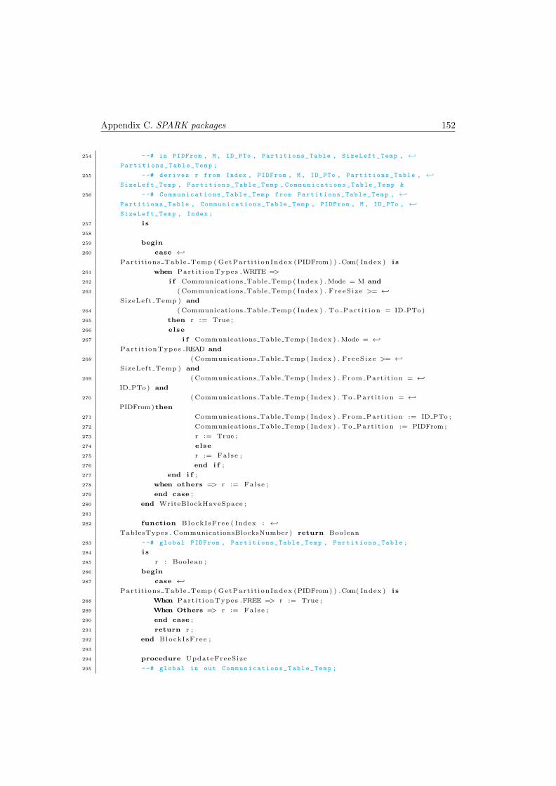
Appendix C. SPARK packages 152
254 --# in PIDFrom , M , ID_PTo , Partitions_Table , SizeLeft_Temp , ←↩
Partitions_Table_Temp ;
255 --# derives r from Index , PIDFrom , M , ID_PTo , Partitions_Table , ←↩
SizeLeft_Temp , Partitions_Table_Temp , Communications_Table_Temp &
256 --# Communications_Table_Temp from Partitions_Table_Temp , ←↩
Partitions_Table , Communications_Table_Temp , PIDFrom , M , ID_PTo , ←↩
SizeLeft_Temp , Index ;
257 i s
258
259 begin
260 case ←↩
Part it ions Table Temp ( GetPart i t ionIndex (PIDFrom) ) .Com( Index ) i s
261 when Part i t ionTypes .WRITE =>
262 i f Communications Table Temp ( Index ) . Mode = M and
263 ( Communications Table Temp ( Index ) . FreeS i ze >= ←↩
SizeLeft Temp ) and
264 ( Communications Table Temp ( Index ) . To Part i t i on = ID PTo)
265 then r := True ;
266 else
267 i f Communications Table Temp ( Index ) . Mode = ←↩
Part i t ionTypes .READ and
268 ( Communications Table Temp ( Index ) . FreeS i ze >= ←↩
SizeLeft Temp ) and
269 ( Communications Table Temp ( Index ) . From Part i t ion = ←↩
ID PTo) and
270 ( Communications Table Temp ( Index ) . To Part i t i on = ←↩
PIDFrom) then
271 Communications Table Temp ( Index ) . From Part i t ion := ID PTo ;
272 Communications Table Temp ( Index ) . To Part i t i on := PIDFrom ;
273 r := True ;
274 else
275 r := False ;
276 end i f ;
277 end i f ;
278 when others => r := False ;
279 end case ;
280 end WriteBlockHaveSpace ;
281
282 function BlockIsFree ( Index : ←↩
TablesTypes . CommunicationsBlocksNumber ) return Boolean
283 --# global PIDFrom , Partitions_Table_Temp , Partitions_Table ;
284 i s
285 r : Boolean ;
286 begin
287 case ←↩
Part it ions Table Temp ( GetPart i t ionIndex (PIDFrom) ) .Com( Index ) i s
288 When Part i t ionTypes .FREE => r := True ;
289 When Others => r := False ;
290 end case ;
291 return r ;
292 end BlockIsFree ;
293
294 procedure UpdateFreeSize
295 --# global in out Communications_Table_Temp ;
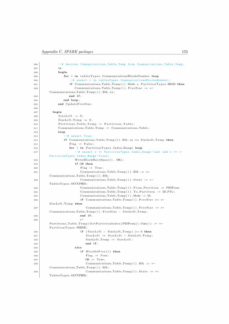
Appendix C. SPARK packages 153
296 --# derives Communications_Table_Temp from Communications_Table_Temp ;
297 i s
298 begin
299 for i in tablesTypes . CommunicationsBlocksNumber loop
300 --# assert i in tablesTypes . CommunicationsBlocksNumber ;
301 i f Communications Table Temp ( i ) . Mode = Part i t ionTypes .READ then
302 Communications Table Temp ( i ) . FreeS i ze := ←↩
Communications Table Temp ( i ) . Blk . sz ;
303 end i f ;
304 end loop ;
305 end UpdateFreeSize ;
306
307 begin
308 S i z e L e f t := S ;
309 SizeLeft Temp := S ;
310 Part it ions Table Temp := Par t i t i on s Tab l e ;
311 Communications Table Temp := Communications Table ;
312 loop
313 --# assert True ;
314 i f Communications Table Temp (1) . Blk . sz >= SizeLeft Temp then
315 Flag := False ;
316 for i in Part i t ionTypes . Index Range loop
317 --# assert i <= PartitionTypes . Index_Range ’ last and i >= ←↩
PartitionTypes . Index_Range ’ first ;
318 WriteBlockHaveSpace ( i , OK) ;
319 i f OK then
320 Flag := True ;
321 Communications Table Temp ( i ) . Blk := ←↩
Communications Table Temp ( i ) . Blk ;
322 Communications Table Temp ( i ) . State := ←↩
TablesTypes .OCCUPIED;
323 Communications Table Temp ( i ) . From Part i t ion := PIDFrom ;
324 Communications Table Temp ( i ) . To Part i t i on := ID PTo ;
325 Communications Table Temp ( i ) . Mode := M;
326 i f Communications Table Temp ( i ) . FreeS i ze >= ←↩
SizeLeft Temp then
327 Communications Table Temp ( i ) . FreeS i ze := ←↩
Communications Table Temp ( i ) . FreeS i ze − SizeLeft Temp ;
328 end i f ;
329 ←↩
Part it ions Table Temp ( GetPart i t ionIndex (PIDFrom) ) .Com( i ) := ←↩
Part i t ionTypes .WRITE;
330 i f ( S i z e L e f t − SizeLeft Temp ) >= 0 then
331 S i z e L e f t := S i z e L e f t − SizeLeft Temp ;
332 SizeLeft Temp := S i z e L e f t ;
333 end i f ;
334 else
335 i f BlockIsFree ( i ) then
336 Flag := True ;
337 OK := True ;
338 Communications Table Temp ( i ) . Blk := ←↩
Communications Table Temp ( i ) . Blk ;
339 Communications Table Temp ( i ) . State := ←↩
TablesTypes .OCCUPIED;
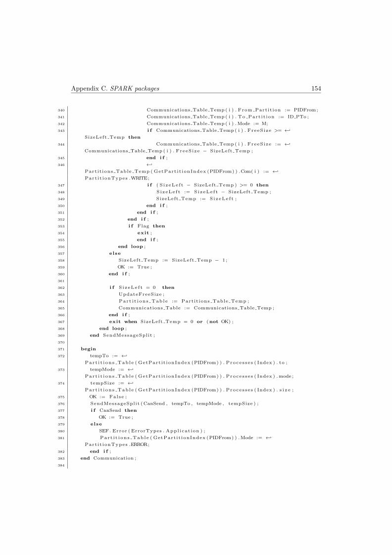
Appendix C. SPARK packages 154
340 Communications Table Temp ( i ) . From Part i t ion := PIDFrom ;
341 Communications Table Temp ( i ) . To Part i t i on := ID PTo ;
342 Communications Table Temp ( i ) . Mode := M;
343 i f Communications Table Temp ( i ) . FreeS i ze >= ←↩
SizeLeft Temp then
344 Communications Table Temp ( i ) . FreeS i ze := ←↩
Communications Table Temp ( i ) . FreeS i ze − SizeLeft Temp ;
345 end i f ;
346 ←↩
Part it ions Table Temp ( GetPart i t ionIndex (PIDFrom) ) .Com( i ) := ←↩
Part i t ionTypes .WRITE;
347 i f ( S i z e L e f t − SizeLeft Temp ) >= 0 then
348 S i z e L e f t := S i z e L e f t − SizeLeft Temp ;
349 SizeLeft Temp := S i z e L e f t ;
350 end i f ;
351 end i f ;
352 end i f ;
353 i f Flag then
354 exit ;
355 end i f ;
356 end loop ;
357 else
358 SizeLeft Temp := SizeLeft Temp − 1 ;
359 OK := True ;
360 end i f ;
361
362 i f S i z e L e f t = 0 then
363 UpdateFreeSize ;
364 Par t i t i on s Tab l e := Part it ions Table Temp ;
365 Communications Table := Communications Table Temp ;
366 end i f ;
367 exit when SizeLeft Temp = 0 or (not OK) ;
368 end loop ;
369 end SendMessageSpl it ;
370
371 begin
372 tempTo := ←↩
Par t i t i on s Tab l e ( GetPart i t ionIndex (PIDFrom) ) . Proce s s e s ( Index ) . to ;
373 tempMode := ←↩
Par t i t i on s Tab l e ( GetPart i t ionIndex (PIDFrom) ) . Proce s s e s ( Index ) . mode ;
374 tempSize := ←↩
Par t i t i on s Tab l e ( GetPart i t ionIndex (PIDFrom) ) . Proce s s e s ( Index ) . s i z e ;
375 OK := False ;
376 SendMessageSpl it (CanSend , tempTo , tempMode , tempSize ) ;
377 i f CanSend then
378 OK := True ;
379 else
380 SEF . Error ( ErrorTypes . Appl i cat ion ) ;
381 Par t i t i on s Tab l e ( GetPart i t ionIndex (PIDFrom) ) . Mode := ←↩
Part i t ionTypes .ERROR;
382 end i f ;
383 end Communication ;
384
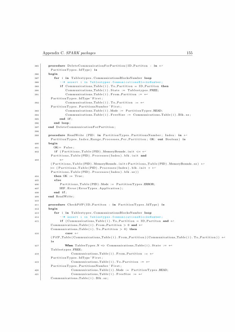
Appendix C. SPARK packages 155
385 procedure DeleteCommunicationForPartit ion ( ID Part i ton : in ←↩
Part i t ionTypes . IdType ) i s
386 begin
387 for i in Tablestypes . CommunicationsBlocksNumber loop
388 --# assert i in Tablestypes . CommunicationsBlocksNumber ;
389 i f Communications Table ( i ) . To Part i t i on = ID Part i ton then
390 Communications Table ( i ) . State := Tablestypes .FREE;
391 Communications Table ( i ) . From Part i t ion := ←↩
Part i t ionTypes . IdType ’ F i r s t ;
392 Communications Table ( i ) . To Part i t i on := ←↩
Part i t ionTypes . PartitionsNumber ’ F i r s t ;
393 Communications Table ( i ) . Mode := Part i t ionTypes .READ;
394 Communications Table ( i ) . FreeS i ze := Communications Table ( i ) . Blk . sz ;
395 end i f ;
396 end loop ;
397 end DeleteCommunicationForPartit ion ;
398
399 procedure ReadWrite (PID : in Part i t ionTypes . Partit ionsNumber ; Index : in ←↩
Part i t ionTypes . Index Range Proce s s e s Pe r Par t i t i t on ; OK: out Boolean ) i s
400 begin
401 OK:= False ;
402 i f ( Pa r t i t i on s Tab l e (PID) . MemoryBounds . i n i t <= ←↩
Par t i t i on s Tab l e (PID) . Proce s s e s ( Index ) . blk . i n i t and
403 ←↩
( Pa r t i t i on s Tab l e (PID) . MemoryBounds . i n i t+Par t i t i on s Tab l e (PID) . MemoryBounds . sz ) ←↩
>= ( Par t i t i on s Tab l e (PID) . Proce s s e s ( Index ) . blk . i n i t + ←↩
Par t i t i on s Tab l e (PID) . Proce s s e s ( Index ) . blk . sz ) )
404 then OK := True ;
405 else
406 Par t i t i on s Tab l e (PID) . Mode := Part i t ionTypes .ERROR;
407 SEF . Error ( ErrorTypes . Appl i cat ion ) ;
408 end i f ;
409 end ReadWrite ;
410
411 procedure CheckPifP ( ID Part i ton : in Part i t ionTypes . IdType ) i s
412 begin
413 for i in Tablestypes . CommunicationsBlocksNumber loop
414 --# assert i in Tablestypes . CommunicationsBlocksNumber ;
415 i f ( Communications Table ( i ) . To Part i t i on = ID Part i ton and ←↩
Communications Table ( i ) . From Part i t ion > 0 and ←↩
Communications Table ( i ) . To Part i t i on > 0) then
416 case ←↩
( Pi fP Table ( Communications Table ( i ) . From Part i t ion ) ( Communications Table ( i ) . To Part i t i on ) ) ←↩
i s
417 When TablesTypes .N => Communications Table ( i ) . State := ←↩
Tablestypes .FREE;
418 Communications Table ( i ) . From Part i t ion := ←↩
Part i t ionTypes . IdType ’ F i r s t ;
419 Communications Table ( i ) . To Part i t i on := ←↩
Part i t ionTypes . PartitionsNumber ’ F i r s t ;
420 Communications Table ( i ) . Mode := Part i t ionTypes .READ;
421 Communications Table ( i ) . FreeS i ze := ←↩
Communications Table ( i ) . Blk . sz ;
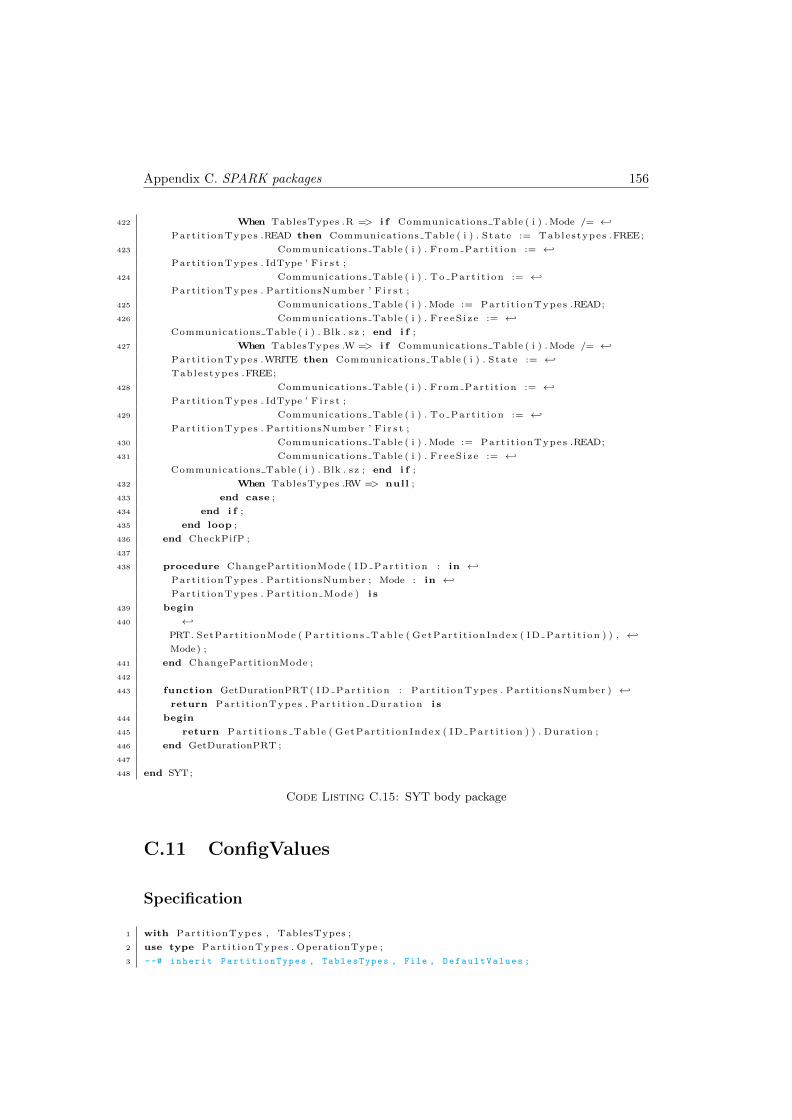
Appendix C. SPARK packages 156
422 When TablesTypes .R => i f Communications Table ( i ) . Mode /= ←↩
Part i t ionTypes .READ then Communications Table ( i ) . State := Tablestypes .FREE;
423 Communications Table ( i ) . From Part i t ion := ←↩
Part i t ionTypes . IdType ’ F i r s t ;
424 Communications Table ( i ) . To Part i t i on := ←↩
Part i t ionTypes . PartitionsNumber ’ F i r s t ;
425 Communications Table ( i ) . Mode := Part i t ionTypes .READ;
426 Communications Table ( i ) . FreeS i ze := ←↩
Communications Table ( i ) . Blk . sz ; end i f ;
427 When TablesTypes .W => i f Communications Table ( i ) . Mode /= ←↩
Part i t ionTypes .WRITE then Communications Table ( i ) . State := ←↩
Tablestypes .FREE;
428 Communications Table ( i ) . From Part i t ion := ←↩
Part i t ionTypes . IdType ’ F i r s t ;
429 Communications Table ( i ) . To Part i t i on := ←↩
Part i t ionTypes . PartitionsNumber ’ F i r s t ;
430 Communications Table ( i ) . Mode := Part i t ionTypes .READ;
431 Communications Table ( i ) . FreeS i ze := ←↩
Communications Table ( i ) . Blk . sz ; end i f ;
432 When TablesTypes .RW => null ;
433 end case ;
434 end i f ;
435 end loop ;
436 end CheckPifP ;
437
438 procedure ChangePartitionMode ( ID Par t i t i on : in ←↩
Part i t ionTypes . Partit ionsNumber ; Mode : in ←↩
Part i t ionTypes . Part it ion Mode ) i s
439 begin
440 ←↩
PRT. SetPart it ionMode ( Pa r t i t i on s Tab l e ( GetPart i t ionIndex ( ID Par t i t i on ) ) , ←↩
Mode) ;
441 end ChangePartitionMode ;
442
443 function GetDurationPRT ( ID Par t i t i on : Part i t ionTypes . Partit ionsNumber ) ←↩
return Part i t ionTypes . Par t i t i on Dura t i on i s
444 begin
445 return Par t i t i on s Tab l e ( GetPart i t ionIndex ( ID Par t i t i on ) ) . Duration ;
446 end GetDurationPRT ;
447
448 end SYT;
Code Listing C.15: SYT body package
C.11 ConfigValues
Specification
1 with Part it ionTypes , TablesTypes ;
2 use type Part i t ionTypes . OperationType ;
3 --# inherit PartitionTypes , TablesTypes , File , DefaultValues ;
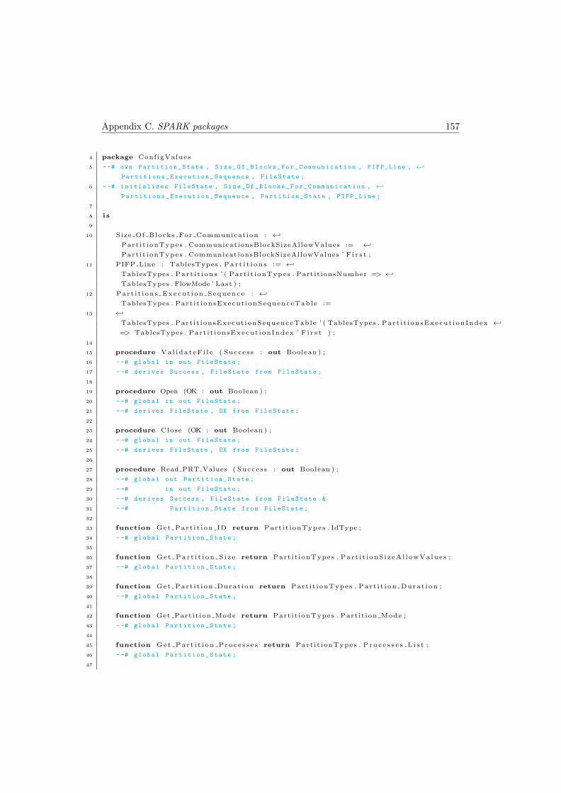
Appendix C. SPARK packages 157
4 package ConfigValues
5 --# own Partition_State , Size_Of_Blocks_For_Communication , PIFP_Line , ←↩
Partitions_Execution_Sequence , FileState ;
6 --# initializes FileState , Size_Of_Blocks_For_Communication , ←↩
Partitions_Execution_Sequence , Partition_State , PIFP_Line ;
7
8 i s
9
10 Size Of Blocks For Communicat ion : ←↩
Part i t ionTypes . CommunicationsBlockSizeAllowValues := ←↩
Part i t ionTypes . CommunicationsBlockSizeAllowValues ’ F i r s t ;
11 PIFP Line : TablesTypes . P a r t i t i o n s := ←↩
TablesTypes . Pa r t i t i on s ’ ( Part i t ionTypes . Partit ionsNumber => ←↩
TablesTypes . FlowMode ’ Last ) ;
12 Part i t i ons Execut i on Sequence : ←↩
TablesTypes . Part i t ionsExecut ionSequenceTable :=
13 ←↩
TablesTypes . Part i t ionsExecut ionSequenceTable ’ ( TablesTypes . Par t i t i onsExecut ionIndex ←↩
=> TablesTypes . Part i t ionsExecut ionIndex ’ F i r s t ) ;
14
15 procedure Va l i da t eF i l e ( Success : out Boolean ) ;
16 --# global in out FileState ;
17 --# derives Success , FileState from FileState ;
18
19 procedure Open (OK : out Boolean ) ;
20 --# global in out FileState ;
21 --# derives FileState , OK from FileState ;
22
23 procedure Close (OK : out Boolean ) ;
24 --# global in out FileState ;
25 --# derives FileState , OK from FileState ;
26
27 procedure Read PRT Values ( Success : out Boolean ) ;
28 --# global out Partition_State ;
29 --# in out FileState ;
30 --# derives Success , FileState from FileState &
31 --# Partition_State from FileState ;
32
33 function Get Part i t i on ID return Part i t ionTypes . IdType ;
34 --# global Partition_State ;
35
36 function G e t P a r t i t i o n S i z e return Part i t ionTypes . Par t i t i onS i zeAl l owVa lues ;
37 --# global Partition_State ;
38
39 function Get Par t i t i on Durat ion return Part i t ionTypes . Par t i t i on Dura t i on ;
40 --# global Partition_State ;
41
42 function Get Part it ion Mode return Part i t ionTypes . Part it ion Mode ;
43 --# global Partition_State ;
44
45 function Get Pa r t i t i on Pro c e s s e s return Part i t ionTypes . P r o c e s s e s L i s t ;
46 --# global Partition_State ;
47
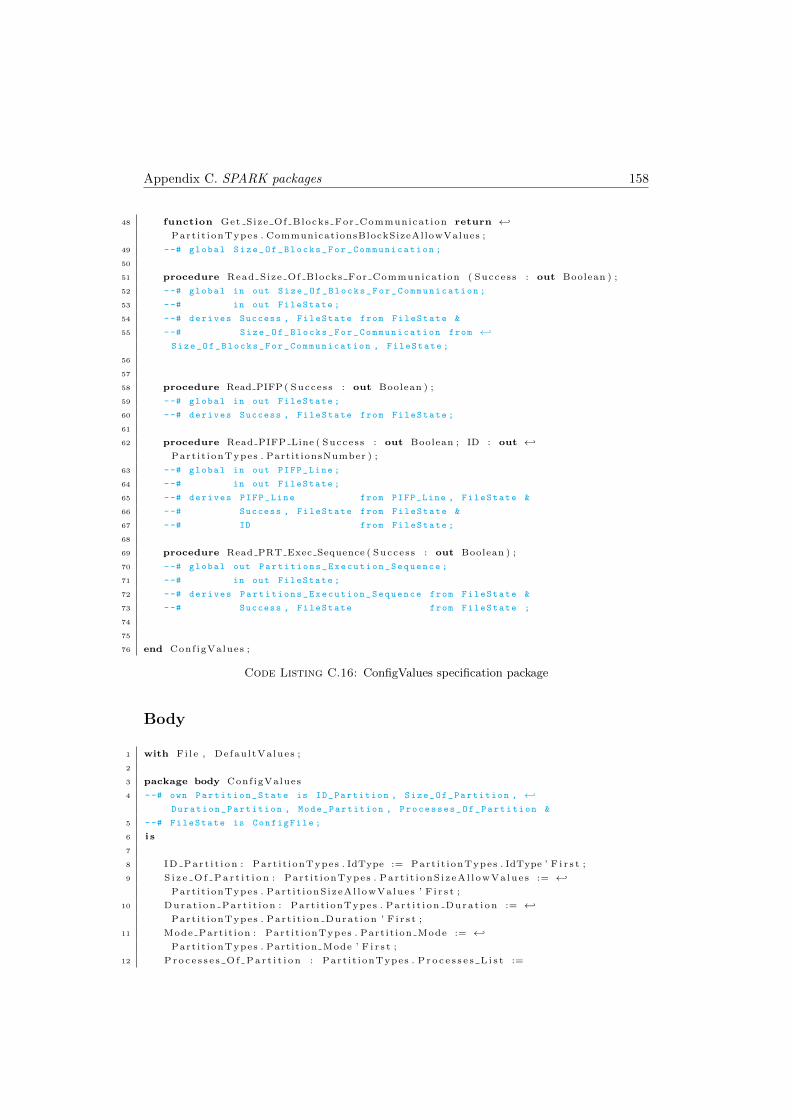
Appendix C. SPARK packages 158
48 function Get Size Of Blocks For Communicat ion return ←↩
Part i t ionTypes . CommunicationsBlockSizeAllowValues ;
49 --# global Size_Of_Blocks_For_Communication ;
50
51 procedure Read Size Of Blocks For Communication ( Success : out Boolean ) ;
52 --# global in out Size_Of_Blocks_For_Communication ;
53 --# in out FileState ;
54 --# derives Success , FileState from FileState &
55 --# Size_Of_Blocks_For_Communication from ←↩
Size_Of_Blocks_For_Communication , FileState ;
56
57
58 procedure Read PIFP ( Success : out Boolean ) ;
59 --# global in out FileState ;
60 --# derives Success , FileState from FileState ;
61
62 procedure Read PIFP Line ( Success : out Boolean ; ID : out ←↩
Part i t ionTypes . Partit ionsNumber ) ;
63 --# global in out PIFP_Line ;
64 --# in out FileState ;
65 --# derives PIFP_Line from PIFP_Line , FileState &
66 --# Success , FileState from FileState &
67 --# ID from FileState ;
68
69 procedure Read PRT Exec Sequence ( Success : out Boolean ) ;
70 --# global out Partitions_Execution_Sequence ;
71 --# in out FileState ;
72 --# derives Partitions_Execution_Sequence from FileState &
73 --# Success , FileState from FileState ;
74
75
76 end ConfigValues ;
Code Listing C.16: ConfigValues specification package
Body
1 with Fi l e , DefaultValues ;
2
3 package body ConfigValues
4 --# own Partition_State is ID_Partition , Size_Of_Partition , ←↩
Duration_Partition , Mode_Partition , Processes_Of_Partition &
5 --# FileState is ConfigFile ;
6 i s
7
8 ID Par t i t i on : Part i t ionTypes . IdType := Part i t ionTypes . IdType ’ F i r s t ;
9 S i z e O f P a r t i t i o n : Part i t ionTypes . Par t i t i onS i zeAl l owVa lues := ←↩
Part i t ionTypes . Part i t i onS izeAl lowValues ’ F i r s t ;
10 Durat i on Par t i t i on : Part i t ionTypes . Par t i t i on Dura t i on := ←↩
Part i t ionTypes . Par t i t i on Durat ion ’ F i r s t ;
11 Mode Part it ion : Part i t ionTypes . Part it ion Mode := ←↩
Part i t ionTypes . Partit ion Mode ’ F i r s t ;
12 P r o c e s s e s O f P a r t i t i o n : Part i t ionTypes . P r o c e s s e s L i s t :=
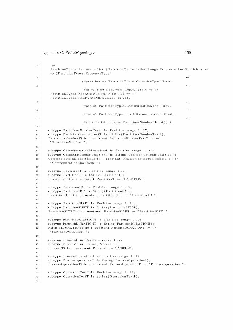
Appendix C. SPARK packages 159
13 ←↩
Part i t ionTypes . P ro c e s s e s L i s t ’ ( Part i t ionTypes . Index Range Proce s s e s Pe r Par t i t i t on ←↩
=> ( Part i t ionTypes . ProcessesType ’
14 ←↩
( operat ion => Part i t ionTypes . OperationType ’ F i r s t ,
15 ←↩
blk => Part i t ionTypes . Tuple2 ’ ( i n i t => ←↩
Part i t ionTypes . AddrAllowValues ’ F i r s t , sz => ←↩
Part i t ionTypes . ReadWriteAllowValues ’ F i r s t ) ,
16 ←↩
mode => Part i t ionTypes . CommunicationMode ’ F i r s t ,
17 ←↩
s i z e => Part i t ionTypes . SizeOfCommunication ’ F i r s t ,
18 ←↩
to => Part i t ionTypes . PartitionsNumber ’ F i r s t ) ) ) ;
19
20 subtype Partit ionsNumberTextI i s P o s i t i v e range 1 . . 1 7 ;
21 subtype PartitionsNumberTextT i s St r ing ( Partit ionsNumberTextI ) ;
22 Part i t ionsNumberTit le : constant PartitionsNumberTextT := ←↩
” Partit ionsNumber ” ;
23
24 subtype CommunicationBlocksSizeI i s P o s i t i v e range 1 . . 2 4 ;
25 subtype CommunicationBlocksSizeT i s St r ing ( CommunicationBlocksSizeI ) ;
26 Communicat ionBlocksSizeTit le : constant CommunicationBlocksSizeT := ←↩
” CommunicationBlocksSize ” ;
27
28 subtype P a r t i t i o n I i s P o s i t i v e range 1 . . 9 ;
29 subtype Part i t ionT i s St r ing ( P a r t i t i o n I ) ;
30 P a r t i t i o n T i t l e : constant Part i t ionT := ”PARTITION” ;
31
32 subtype Par t i t i on IDI i s P o s i t i v e range 1 . . 1 2 ;
33 subtype Partit ionIDT i s St r ing ( Par t i t i on IDI ) ;
34 Par t i t i on IDTi t l e : constant Partit ionIDT := ” Part i t i onID ” ;
35
36 subtype Part i t ionSIZEI i s P o s i t i v e range 1 . . 1 4 ;
37 subtype Partit ionSIZET i s St r ing ( Part i t i onSIZEI ) ;
38 Par t i t i onSIZETi t l e : constant Partit ionSIZET := ” Part i t ionSIZE ” ;
39
40 subtype PartitionDURATIONI i s P o s i t i v e range 1 . . 1 8 ;
41 subtype PartitionDURATIONT i s St r ing ( PartitionDURATIONI ) ;
42 PartitionDURATIONTitle : constant PartitionDURATIONT := ←↩
”PartitionDURATION ” ;
43
44 subtype Proce s s I i s P o s i t i v e range 1 . . 7 ;
45 subtype ProcessT i s St r ing ( Proce s s I ) ;
46 Proc e s sT i t l e : constant ProcessT := ”PROCESS” ;
47
48 subtype ProcessOperat ionI i s P o s i t i v e range 1 . . 1 7 ;
49 subtype ProcessOperationT i s St r ing ( ProcessOperat ionI ) ;
50 Proces sOperat ionTi t l e : constant ProcessOperationT := ” ProcessOperat ion ” ;
51
52 subtype OperationTextI i s P o s i t i v e range 1 . . 1 3 ;
53 subtype OperationTextT i s St r ing ( OperationTextI ) ;
54
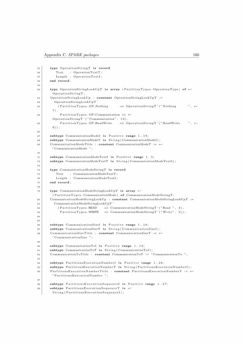
Appendix C. SPARK packages 160
55 type OperationStr ingT i s record
56 Text : OperationTextT ;
57 Length : OperationTextI ;
58 end record ;
59
60 type OperationStringLookUpT i s array ( Part i t ionTypes . OperationType ) of ←↩
OperationStr ingT ;
61 OperationStringLookUp : constant OperationStringLookUpT :=
62 OperationStringLookUpT ’
63 ( Part i t ionTypes . OP Nothing => OperationStringT ’ ( ”Nothing ” , ←↩
7) ,
64 Part i t ionTypes . OP Communication => ←↩
OperationStringT ’ ( ”Communication” , 13) ,
65 Part i t ionTypes . OP ReadWrite => OperationStringT ’ ( ”ReadWrite ” , ←↩
9) ) ;
66
67 subtype CommunicationModeI i s P o s i t i v e range 1 . . 1 8 ;
68 subtype CommunicationModeT i s St r ing ( CommunicationModeI ) ;
69 CommunicationModeTitle : constant CommunicationModeT := ←↩
”CommunicationMode ” ;
70
71 subtype CommunicationModeTextI i s P o s i t i v e range 1 . . 5 ;
72 subtype CommunicationModeTextT i s St r ing ( CommunicationModeTextI ) ;
73
74 type CommunicationModeStringT i s record
75 Text : CommunicationModeTextT ;
76 Length : CommunicationModeTextI ;
77 end record ;
78
79 type CommunicationModeStringLookUpT i s array ←↩
( Part i t ionTypes . CommunicationMode ) of CommunicationModeStringT ;
80 CommunicationModeStringLookUp : constant CommunicationModeStringLookUpT :=
81 CommunicationModeStringLookUpT ’
82 ( Part i t ionTypes .READ => CommunicationModeStringT ’ ( ”Read ” , 4) ,
83 Part i t ionTypes .WRITE => CommunicationModeStringT ’ ( ”Write” , 5) ) ;
84
85
86 subtype CommunicationSizeI i s P o s i t i v e range 1 . . 1 8 ;
87 subtype CommunicationSizeT i s St r ing ( CommunicationSizeI ) ;
88 CommunicationSizeTit le : constant CommunicationSizeT := ←↩
”CommunicationSize ” ;
89
90 subtype CommunicationToI i s P o s i t i v e range 1 . . 1 6 ;
91 subtype CommunicationToT i s St r ing ( CommunicationToI ) ;
92 CommunicationToTitle : constant CommunicationToT := ”CommunicationTo ” ;
93
94 subtype Part it ionsExecut ionNumberI i s P o s i t i v e range 1 . . 2 6 ;
95 subtype PartitionsExecutionNumberT i s St r ing ( Part it ionsExecut ionNumberI ) ;
96 Part i t ionsExecut ionNumberTit le : constant PartitionsExecutionNumberT := ←↩
” Partit ionsExecutionNumber ” ;
97
98 subtype Part i t i onsExecut ionSequence I i s P o s i t i v e range 1 . . 2 7 ;
99 subtype Part i t ionsExecut ionSequenceT i s ←↩
St r ing ( Par t i t i onsExecut ionSequence I ) ;
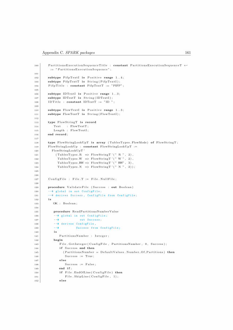
Appendix C. SPARK packages 161
100 Part i t i on sExecut i onSequenceT i t l e : constant Part i t ionsExecut ionSequenceT ←↩
:= ” Part i t i onsExecut ionSequence ” ;
101
102 subtype PifpTextI i s P o s i t i v e range 1 . . 4 ;
103 subtype PifpTextT i s St r ing ( Pi fpTextI ) ;
104 P i f p T i t l e : constant PifpTextT := ”PIFP” ;
105
106 subtype IDTextI i s P o s i t i v e range 1 . . 3 ;
107 subtype IDTextT i s St r ing ( IDTextI ) ;
108 IDTit l e : constant IDTextT := ”ID ” ;
109
110 subtype FlowTextI i s P o s i t i v e range 1 . . 3 ;
111 subtype FlowTextT i s St r ing ( FlowTextI ) ;
112
113 type FlowStringT i s record
114 Text : FlowTextT ;
115 Length : FlowTextI ;
116 end record ;
117
118 type FlowStringLookUpT i s array ( TablesTypes . FlowMode) of FlowStringT ;
119 FlowStringLookUp : constant FlowStringLookUpT :=
120 FlowStringLookUpT ’
121 ( TablesTypes .R => FlowStringT ’ ( ” R ” , 2) ,
122 TablesTypes .W => FlowStringT ’ ( ” W ” , 2) ,
123 TablesTypes .RW => FlowStringT ’ ( ” RW” , 3) ,
124 TablesTypes .N => FlowStringT ’ ( ” N ” , 2) ) ;
125
126
127 Con f i gF i l e : F i l e .T := F i l e . Nu l lF i l e ;
128
129 procedure Va l i da t eF i l e ( Success : out Boolean )
130 --# global in out ConfigFile ;
131 --# derives Success , ConfigFile from ConfigFile ;
132 i s
133 OK : Boolean ;
134
135 procedure ReadPartitionsNumberValue
136 --# global in out ConfigFile ;
137 --# out Success ;
138 --# derives ConfigFile ,
139 --# Success from ConfigFile ;
140 i s
141 Partit ionsNumber : I n t eg e r ;
142 begin
143 F i l e . GetInteger ( Conf igFi l e , PartitionsNumber , 0 , Success ) ;
144 i f Success and then
145 ( Partit ionsNumber = DefaultValues . Number Of Part it ions ) then
146 Success := True ;
147 else
148 Success := False ;
149 end i f ;
150 i f F i l e . EndOfLine ( Con f i gF i l e ) then
151 F i l e . SkipLine ( Conf igFi l e , 1) ;
152 else
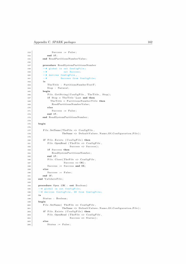
Appendix C. SPARK packages 162
153 Success := False ;
154 end i f ;
155 end ReadPartitionsNumberValue ;
156
157 procedure ReadSystemPartitionsNumber
158 --# global in out ConfigFile ;
159 --# out Success ;
160 --# derives ConfigFile ,
161 --# Success from ConfigFile ;
162 i s
163 TheTit le : PartitionsNumberTextT ;
164 Stop : Natural ;
165 begin
166 F i l e . GetStr ing ( Conf igFi l e , TheTitle , Stop ) ;
167 i f Stop = TheTitle ’ Last and then
168 TheTit le = Part i t ionsNumberTit le then
169 ReadPartitionsNumberValue ;
170 else
171 Success := False ;
172 end i f ;
173 end ReadSystemPartitionsNumber ;
174
175 begin
176
177 F i l e . SetName( TheFile => Conf igFi l e ,
178 TheName => DefaultValues . Name Of Conf igurat ion Fi le ) ;
179
180 i f F i l e . Ex i s t s ( Con f i gF i l e ) then
181 F i l e . OpenRead ( TheFile => Conf igFi l e ,
182 Success => Success ) ;
183 i f Success then
184 ReadSystemPartitionsNumber ;
185 end i f ;
186 F i l e . Close ( TheFile => Conf igFi l e ,
187 Success => OK) ;
188 Success := Success and OK;
189 else
190 Success := False ;
191 end i f ;
192 end Va l i da t eF i l e ;
193
194 procedure Open (OK : out Boolean )
195 --# global in out ConfigFile ;
196 --# derives ConfigFile , OK from ConfigFile ;
197 i s
198 Status : Boolean ;
199 begin
200 F i l e . SetName( TheFile => Conf igFi l e ,
201 TheName => DefaultValues . Name Of Conf igurat ion Fi le ) ;
202 i f F i l e . Ex i s t s ( Con f i gF i l e ) then
203 F i l e . OpenRead ( TheFile => Conf igFi l e ,
204 Success => Status ) ;
205 else
206 Status := False ;

Appendix C. SPARK packages 163
207 end i f ;
208 OK := Status ;
209 end Open ;
210
211 procedure Close (OK : out Boolean )
212 --# global in out ConfigFile ;
213 --# derives ConfigFile , OK from ConfigFile ;
214 i s
215 Status : Boolean ;
216 begin
217 F i l e . Close ( TheFile => Conf igFi l e ,
218 Success => Status ) ;
219 OK := Status ;
220 end Close ;
221
222 procedure Read PRT Values ( Success : out Boolean )
223 --# global out ID_Partition , Size_Of_Partition , Duration_Partition , ←↩
Mode_Partition , Processes_Of_Partition ;
224 --# in out ConfigFile ;
225 --# derives Success , ConfigFile from ConfigFile &
226 --# ID_Partition , Size_Of_Partition , Duration_Partition , ←↩
Mode_Partition , Processes_Of_Partition from ConfigFile ;
227
228 i s
229 Process : Part i t ionTypes . ProcessesType ;
230
231 procedure ReadPar t i t i onTi t l e
232 --# global in out ConfigFile ;
233 --# out Success ;
234 --# derives ConfigFile ,
235 --# Success from ConfigFile ;
236 i s
237 TheTit le : Part i t ionT ;
238 Stop : Natural ;
239 begin
240 F i l e . GetStr ing ( Conf igFi l e , TheTitle , Stop ) ;
241 i f Stop = TheTitle ’ Last and then
242 TheTit le = P a r t i t i o n T i t l e then
243 i f F i l e . EndOfLine ( Con f i gF i l e ) then
244 F i l e . SkipLine ( Conf igFi l e , 1) ;
245 Success := True ;
246 else
247 Success := False ;
248 end i f ;
249 else
250 Success := False ;
251 end i f ;
252 end ReadPar t i t i onTi t l e ;
253
254 procedure ReadPartit ionID
255 --# global in out ConfigFile ;
256 --# out Success ;
257 --# out ID_Partition ;
258 --# derives ConfigFile , Success from ConfigFile &
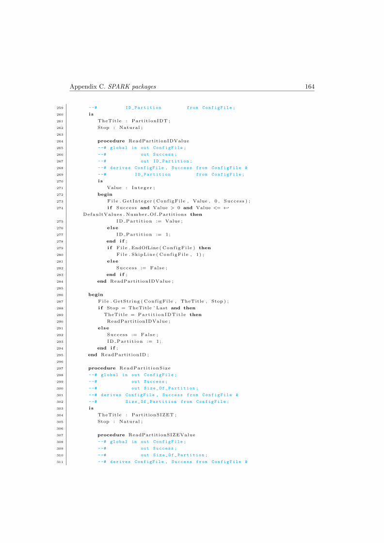
Appendix C. SPARK packages 164
259 --# ID_Partition from ConfigFile ;
260 i s
261 TheTit le : Part it ionIDT ;
262 Stop : Natural ;
263
264 procedure ReadPartit ionIDValue
265 --# global in out ConfigFile ;
266 --# out Success ;
267 --# out ID_Partition ;
268 --# derives ConfigFile , Success from ConfigFile &
269 --# ID_Partition from ConfigFile ;
270 i s
271 Value : In t eg e r ;
272 begin
273 F i l e . GetInteger ( Conf igFi l e , Value , 0 , Success ) ;
274 i f Success and Value > 0 and Value <= ←↩
DefaultValues . Number Of Part it ions then
275 ID Par t i t i on := Value ;
276 else
277 ID Par t i t i on := 1 ;
278 end i f ;
279 i f F i l e . EndOfLine ( Con f i gF i l e ) then
280 F i l e . SkipLine ( Conf igFi l e , 1) ;
281 else
282 Success := False ;
283 end i f ;
284 end ReadPartit ionIDValue ;
285
286 begin
287 F i l e . GetStr ing ( Conf igFi l e , TheTitle , Stop ) ;
288 i f Stop = TheTitle ’ Last and then
289 TheTit le = Par t i t i on IDTi t l e then
290 ReadPartit ionIDValue ;
291 else
292 Success := False ;
293 ID Par t i t i on := 1 ;
294 end i f ;
295 end ReadPartit ionID ;
296
297 procedure ReadPart i t i onS ize
298 --# global in out ConfigFile ;
299 --# out Success ;
300 --# out Size_Of_Partition ;
301 --# derives ConfigFile , Success from ConfigFile &
302 --# Size_Of_Partition from ConfigFile ;
303 i s
304 TheTit le : Partit ionSIZET ;
305 Stop : Natural ;
306
307 procedure ReadPartitionSIZEValue
308 --# global in out ConfigFile ;
309 --# out Success ;
310 --# out Size_Of_Partition ;
311 --# derives ConfigFile , Success from ConfigFile &
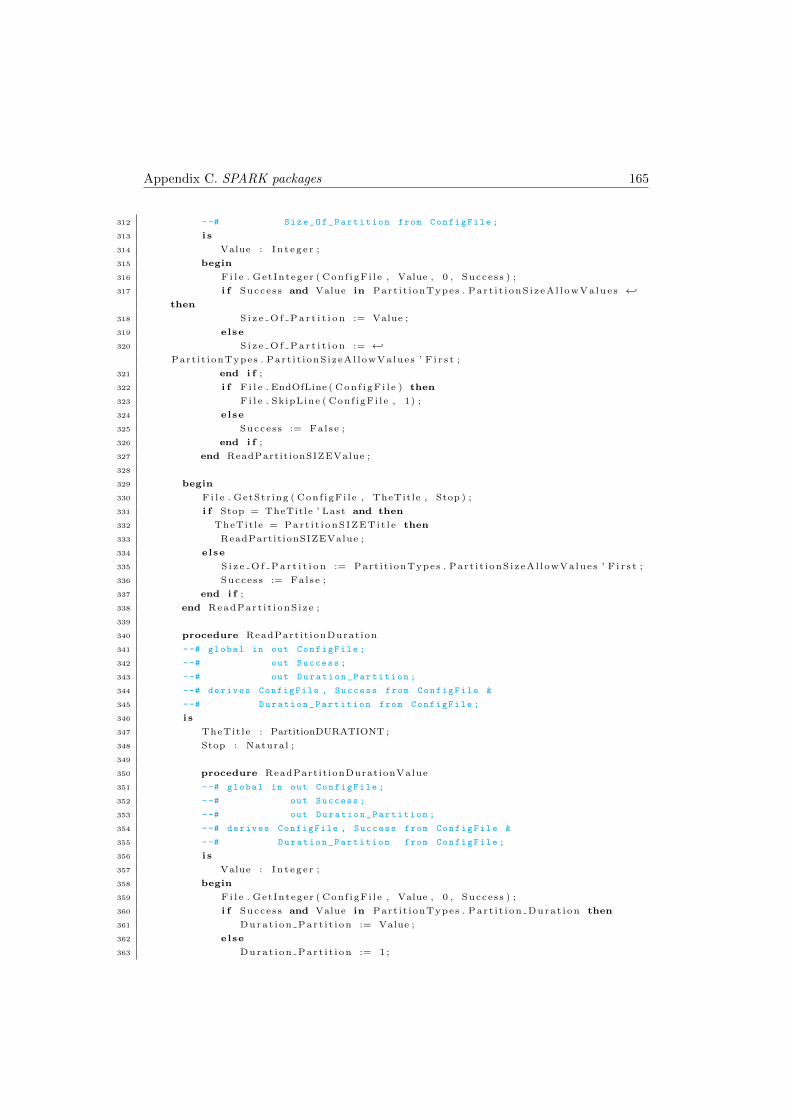
Appendix C. SPARK packages 165
312 --# Size_Of_Partition from ConfigFile ;
313 i s
314 Value : In t eg e r ;
315 begin
316 F i l e . GetInteger ( Conf igFi l e , Value , 0 , Success ) ;
317 i f Success and Value in Part i t ionTypes . Par t i t i onS i zeAl l owVa lues ←↩
then
318 S i z e O f P a r t i t i o n := Value ;
319 else
320 S i z e O f P a r t i t i o n := ←↩
Part i t ionTypes . Part i t i onS izeAl lowValues ’ F i r s t ;
321 end i f ;
322 i f F i l e . EndOfLine ( Con f i gF i l e ) then
323 F i l e . SkipLine ( Conf igFi l e , 1) ;
324 else
325 Success := False ;
326 end i f ;
327 end ReadPartitionSIZEValue ;
328
329 begin
330 F i l e . GetStr ing ( Conf igFi l e , TheTitle , Stop ) ;
331 i f Stop = TheTitle ’ Last and then
332 TheTit le = Par t i t i onSIZETi t l e then
333 ReadPartitionSIZEValue ;
334 else
335 S i z e O f P a r t i t i o n := Part i t ionTypes . Part i t i onS izeAl lowValues ’ F i r s t ;
336 Success := False ;
337 end i f ;
338 end ReadPart i t i onS ize ;
339
340 procedure ReadPart it ionDurat ion
341 --# global in out ConfigFile ;
342 --# out Success ;
343 --# out Duration_Partition ;
344 --# derives ConfigFile , Success from ConfigFile &
345 --# Duration_Partition from ConfigFile ;
346 i s
347 TheTit le : PartitionDURATIONT ;
348 Stop : Natural ;
349
350 procedure ReadPart it ionDurationValue
351 --# global in out ConfigFile ;
352 --# out Success ;
353 --# out Duration_Partition ;
354 --# derives ConfigFile , Success from ConfigFile &
355 --# Duration_Partition from ConfigFile ;
356 i s
357 Value : In t eg e r ;
358 begin
359 F i l e . GetInteger ( Conf igFi l e , Value , 0 , Success ) ;
360 i f Success and Value in Part i t ionTypes . Par t i t i on Dura t i on then
361 Durat i on Par t i t i on := Value ;
362 else
363 Durat i on Par t i t i on := 1 ;
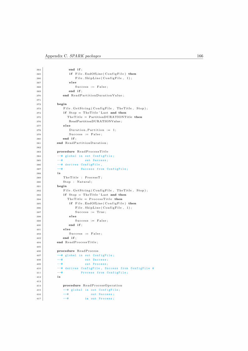
Appendix C. SPARK packages 166
364 end i f ;
365 i f F i l e . EndOfLine ( Con f i gF i l e ) then
366 F i l e . SkipLine ( Conf igFi l e , 1) ;
367 else
368 Success := False ;
369 end i f ;
370 end ReadPart it ionDurationValue ;
371
372 begin
373 F i l e . GetStr ing ( Conf igFi l e , TheTitle , Stop ) ;
374 i f Stop = TheTitle ’ Last and then
375 TheTit le = PartitionDURATIONTitle then
376 ReadPartitionDURATIONValue ;
377 else
378 Durat i on Par t i t i on := 1 ;
379 Success := False ;
380 end i f ;
381 end ReadPart it ionDurat ion ;
382
383 procedure ReadProcessTit le
384 --# global in out ConfigFile ;
385 --# out Success ;
386 --# derives ConfigFile ,
387 --# Success from ConfigFile ;
388 i s
389 TheTit le : ProcessT ;
390 Stop : Natural ;
391 begin
392 F i l e . GetStr ing ( Conf igFi l e , TheTitle , Stop ) ;
393 i f Stop = TheTitle ’ Last and then
394 TheTit le = Proc e s sT i t l e then
395 i f F i l e . EndOfLine ( Con f i gF i l e ) then
396 F i l e . SkipLine ( Conf igFi l e , 1) ;
397 Success := True ;
398 else
399 Success := False ;
400 end i f ;
401 else
402 Success := False ;
403 end i f ;
404 end ReadProcessTit le ;
405
406 procedure ReadProcess
407 --# global in out ConfigFile ;
408 --# out Success ;
409 --# out Process ;
410 --# derives ConfigFile , Success from ConfigFile &
411 --# Process from ConfigFile ;
412 i s
413
414 procedure ReadProcessOperation
415 --# global in out ConfigFile ;
416 --# out Success ;
417 --# in out Process ;
Appendix C. SPARK packages 167
418 --# derives ConfigFile , Success from ConfigFile &
419 --# Process from Process , ConfigFile ;
420 i s
421 TheTit le : ProcessOperationT ;
422 RawOperation : OperationTextT ;
423 Stop : Natural ;
424 Matched : Boolean := False ;
425
426 begin
427 Process . operat ion := Part i t ionTypes . OperationType ’ F i r s t ;
428 F i l e . GetStr ing ( Conf igFi l e , TheTitle , Stop ) ;
429 i f Stop = TheTitle ’ Last and then
430 TheTit le = Proce s sOperat i onTi t l e then
431
432 F i l e . GetLine ( Conf igFi l e , RawOperation , Stop ) ;
433 for OP in Part i t ionTypes . OperationType loop
434 --# assert OP in PartitionTypes . OperationType ;
435 i f Stop = OperationStringLookUp (OP) . Length then
436 --# assert OP in PartitionTypes . OperationType and
437 --# Stop in OperationTextI ;
438 Matched := True ;
439 for I in OperationTextI range 1 . . Stop loop
440 --# assert OP in PartitionTypes . OperationType and
441 --# Stop in OperationTextI and
442 --# Stop = Stop % and
443 --# I in OperationTextI and
444 --# I <= Stop ;
445 i f OperationStringLookUp (OP) . Text ( I ) /= ←↩
RawOperation ( I ) then
446 Matched := False ;
447 exit ;
448 end i f ;
449 end loop ;
450 end i f ;
451 i f Matched then
452 Process . operat ion := OP;
453 exit ;
454 end i f ;
455 end loop ;
456 Success := Matched ;
457 else
458 Success := False ;
459 end i f ;
460 end ReadProcessOperation ;
461
462 procedure ReadProcessCommunicationMode
463 --# global in out ConfigFile ;
464 --# out Success ;
465 --# in out Process ;
466 --# derives ConfigFile , Success from ConfigFile &
467 --# Process from Process , ConfigFile ;
468 i s
469 TheTit le : CommunicationModeT ;
470 RawMode : CommunicationModeTextT ;
Appendix C. SPARK packages 168
471 Stop : Natural ;
472 Matched : Boolean := False ;
473
474 begin
475 Process . mode := Part i t ionTypes .READ;
476 F i l e . GetStr ing ( Conf igFi l e , TheTitle , Stop ) ;
477 i f Stop = TheTitle ’ Last and then
478 TheTit le = CommunicationModeTitle then
479 F i l e . GetLine ( Conf igFi l e , RawMode , Stop ) ;
480 for M in Part i t ionTypes . CommunicationMode loop
481 --# assert M in PartitionTypes . CommunicationMode ;
482 i f Stop = CommunicationModeStringLookUp (M) . Length then
483 --# assert M in PartitionTypes . CommunicationMode and
484 --# Stop in CommunicationModeTextI ;
485 Matched := True ;
486 for I in CommunicationModeTextI range 1 . . Stop loop
487 --# assert M in PartitionTypes . CommunicationMode and
488 --# Stop in CommunicationModeTextI and
489 --# Stop = Stop % and
490 --# I in CommunicationModeTextI and
491 --# I <= Stop ;
492 i f CommunicationModeStringLookUp (M) . Text ( I ) /= ←↩
RawMode( I ) then
493 Matched := False ;
494 exit ;
495 end i f ;
496 end loop ;
497 end i f ;
498 i f Matched then
499 Process . mode := M;
500 exit ;
501 end i f ;
502 end loop ;
503 Success := Matched ;
504 else
505 Success := False ;
506 end i f ;
507 end ReadProcessCommunicationMode ;
508
509 procedure ReadProcessCommunicationSize
510 --# global in out ConfigFile ;
511 --# out Success ;
512 --# in out Process ;
513 --# derives ConfigFile , Success from ConfigFile &
514 --# Process from Process , ConfigFile ;
515 i s
516 TheTit le : CommunicationSizeT ;
517 Stop : Natural ;
518
519 procedure ReadProcessCommunicationSizeValue
520 --# global in out ConfigFile ;
521 --# out Success ;
522 --# in out Process ;
523 --# derives ConfigFile , Success from ConfigFile &

Appendix C. SPARK packages 169
524 --# Process from Process , ConfigFile ;
525 i s
526 Value : In t eg e r ;
527 begin
528 Process . s i z e := 2 ;
529 F i l e . GetInteger ( Conf igFi l e , Value , 0 , Success ) ;
530 i f Success and Value in ←↩
Part i t ionTypes . CommunicationsBlockSizeAllowValues then
531 Process . s i z e := Value ;
532 end i f ;
533 i f F i l e . EndOfLine ( Con f i gF i l e ) then
534 F i l e . SkipLine ( Conf igFi l e , 1) ;
535 else
536 Success := False ;
537 end i f ;
538 end ReadProcessCommunicationSizeValue ;
539
540 begin
541 Process . s i z e := 2 ;
542 F i l e . GetStr ing ( Conf igFi l e , TheTitle , Stop ) ;
543 i f Stop = TheTitle ’ Last and then
544 TheTit le = CommunicationSizeTit le then
545 ReadProcessCommunicationSizeValue ;
546 else
547 Success := False ;
548 end i f ;
549 end ReadProcessCommunicationSize ;
550
551 procedure ReadProcessCommunicationTo
552 --# global in out ConfigFile ;
553 --# out Success ;
554 --# in out Process ;
555 --# derives ConfigFile , Success from ConfigFile &
556 --# Process from Process , ConfigFile ;
557 i s
558 TheTit le : CommunicationToT ;
559 Stop : Natural ;
560
561 procedure ReadProcessCommunicationToValue
562 --# global in out ConfigFile ;
563 --# out Success ;
564 --# in out Process ;
565 --# derives ConfigFile , Success from ConfigFile &
566 --# Process from Process , ConfigFile ;
567 i s
568 Value : In t eg e r ;
569 begin
570 Process . to := Part i t ionTypes . PartitionsNumber ’ F i r s t ;
571 F i l e . GetInteger ( Conf igFi l e , Value , 0 , Success ) ;
572 i f Success and Value > 0 and Value <= ←↩
DefaultValues . Number Of Part it ions then
573 Process . to := Value ;
574 end i f ;
575 i f F i l e . EndOfLine ( Con f i gF i l e ) then
Appendix C. SPARK packages 170
576 F i l e . SkipLine ( Conf igFi l e , 1) ;
577 else
578 Success := False ;
579 end i f ;
580 end ReadProcessCommunicationToValue ;
581
582 begin
583 Process . to := Part i t ionTypes . PartitionsNumber ’ F i r s t ;
584 F i l e . GetStr ing ( Conf igFi l e , TheTitle , Stop ) ;
585 i f Stop = TheTitle ’ Last and then
586 TheTit le = CommunicationToTitle then
587 ReadProcessCommunicationToValue ;
588 else
589 Success := False ;
590 end i f ;
591 end ReadProcessCommunicationTo ;
592
593
594 begin
595 Process . operat ion := Part i t ionTypes . OP Communication ;
596 Process . blk . i n i t := 1 ;
597 Process . blk . sz := 1 ;
598 Process . mode := Part i t ionTypes .READ;
599 Process . s i z e := 2 ;
600 Process . to := Part i t ionTypes . PartitionsNumber ’ F i r s t ;
601
602 ReadProcessOperation ;
603 i f Process . operat ion = Part i t ionTypes . OP Communication then
604 ReadProcessCommunicationMode ;
605 i f Success then
606 ReadProcessCommunicationSize ;
607 end i f ;
608 i f Success then
609 ReadProcessCommunicationTo ;
610 end i f ;
611 end i f ;
612 end ReadProcess ;
613
614 begin
615
616 ID Par t i t i on := 1 ;
617 S i z e O f P a r t i t i o n := Part i t ionTypes . Part i t i onS izeAl lowValues ’ F i r s t ;
618 Durat i on Par t i t i on := 1 ;
619 Mode Part it ion := Part i t ionTypes . IDLE ;
620 Process . operat ion := Part i t ionTypes . OP Nothing ;
621 Process . blk . i n i t := 1 ;
622 Process . blk . sz := 1 ;
623 Process . mode := Part i t ionTypes .READ;
624 Process . s i z e := 2 ;
625 Process . to := Part i t ionTypes . PartitionsNumber ’ F i r s t ;
626 P r o c e s s e s O f P a r t i t i o n := ←↩
Part i t ionTypes . P ro c e s s e s L i s t ’ ( Part i t ionTypes . Index Range Proce s s e s Pe r Par t i t i t on ←↩
=> Process ) ;
627 ReadPar t i t i onTi t l e ;
Appendix C. SPARK packages 171
628 i f Success then
629 ReadPartit ionID ;
630 --# assert True ;
631 i f Success then
632 ReadPart i t i onS ize ;
633 end i f ;
634 --# assert True ;
635 i f Success then
636 ReadPart it ionDurat ion ;
637 end i f ;
638 i f Success then
639 for i in Part i t ionTypes . Index Range Proce s s e s Pe r Par t i t i t on loop
640 --# assert i in ←↩
PartitionTypes . Index_Range_Processes_Per_Partititon ;
641 ReadProcessTit le ;
642 --# assert True ;
643 i f Success then
644 ReadProcess ;
645 end i f ;
646 --# assert True ;
647 P r o c e s s e s O f P a r t i t i o n ( i ) := Process ;
648 end loop ;
649 end i f ;
650 i f Success then
651 Mode Part it ion := Part i t ionTypes . IDLE ;
652 end i f ;
653 end i f ;
654
655 end Read PRT Values ;
656
657 function Get Part i t i on ID return Part i t ionTypes . IdType
658 --# global ID_Partition ;
659 i s
660 begin
661 return ID Par t i t i on ;
662 end Get Part i t i on ID ;
663
664 function G e t P a r t i t i o n S i z e return Part i t ionTypes . Par t i t i onS i zeAl l owVa lues
665 --# global Size_Of_Partition ;
666 i s
667 begin
668 return S i z e O f P a r t i t i o n ;
669 end G e t P a r t i t i o n S i z e ;
670
671
672 function Get Par t i t i on Durat ion return Part i t ionTypes . Par t i t i on Dura t i on
673 --# global Duration_Partition ;
674 i s
675 begin
676 return Durat i on Par t i t i on ;
677 end Get Par t i t i on Durat ion ;
678
679 function Get Part it ion Mode return Part i t ionTypes . Part it ion Mode
680 --# global Mode_Partition ;

Appendix C. SPARK packages 172
681 i s
682 begin
683 return Mode Part it ion ;
684 end Get Part it ion Mode ;
685
686 function Get Pa r t i t i on Pro c e s s e s return Part i t ionTypes . P r o c e s s e s L i s t
687 --# global Processes_Of_Partition ;
688 i s
689 begin
690 return P r o c e s s e s O f P a r t i t i o n ;
691 end Ge t Pa r t i t i on Pro c e s s e s ;
692
693 procedure Read Size Of Blocks For Communication ( Success : out Boolean )
694 --# global in out Size_Of_Blocks_For_Communication ;
695 --# in out ConfigFile ;
696 --# derives Success , ConfigFile from ConfigFile &
697 --# Size_Of_Blocks_For_Communication from ←↩
Size_Of_Blocks_For_Communication , ConfigFile ;
698
699 i s
700 procedure SetDe fau l t s
701 --# global out Size_Of_Blocks_For_Communication ;
702 --# derives Size_Of_Blocks_For_Communication from ;
703 i s
704 begin
705 Size Of Blocks For Communicat ion := 4 ;
706 end SetDe fau l t s ;
707
708 procedure ReadCommunicationBlocksSizeValue
709 --# global in out ConfigFile ;
710 --# out Success ;
711 --# in out Size_Of_Blocks_For_Communication ;
712 --# derives ConfigFile ,
713 --# Success from ConfigFile &
714 --# Size_Of_Blocks_For_Communication from ←↩
Size_Of_Blocks_For_Communication , ConfigFile ;
715 i s
716 Value : In t eg e r ;
717 begin
718 F i l e . GetInteger ( Conf igFi l e , Value , 0 , Success ) ;
719 i f Success and then
720 ( Value >= 1 and Value <= ←↩
DefaultValues . CommunicationsBlockSizeMaxValue ) then
721 Success := True ;
722 Size Of Blocks For Communicat ion := Value ;
723 else
724 Success := False ;
725 end i f ;
726
727 i f F i l e . EndOfLine ( Con f i gF i l e ) then
728 F i l e . SkipLine ( Conf igFi l e , 1) ;
729 F i l e . SkipLine ( Conf igFi l e , 1) ;
730 else
731 Success := False ;
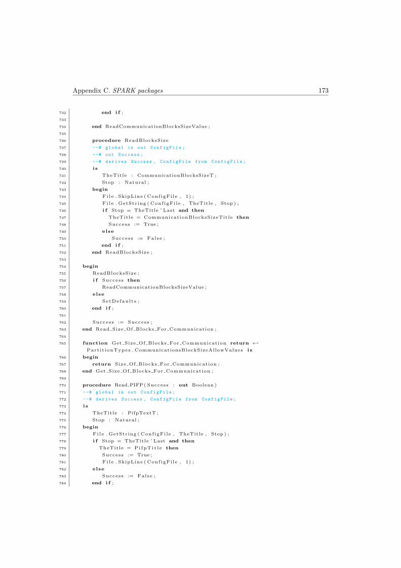
Appendix C. SPARK packages 173
732 end i f ;
733
734 end ReadCommunicationBlocksSizeValue ;
735
736 procedure ReadBlocksSize
737 --# global in out ConfigFile ;
738 --# out Success ;
739 --# derives Success , ConfigFile from ConfigFile ;
740 i s
741 TheTit le : CommunicationBlocksSizeT ;
742 Stop : Natural ;
743 begin
744 F i l e . SkipLine ( Conf igFi l e , 1) ;
745 F i l e . GetStr ing ( Conf igFi l e , TheTitle , Stop ) ;
746 i f Stop = TheTitle ’ Last and then
747 TheTit le = Communicat ionBlocksSizeTit le then
748 Success := True ;
749 else
750 Success := False ;
751 end i f ;
752 end ReadBlocksSize ;
753
754 begin
755 ReadBlocksSize ;
756 i f Success then
757 ReadCommunicationBlocksSizeValue ;
758 else
759 SetDe fau l t s ;
760 end i f ;
761
762 Success := Success ;
763 end Read Size Of Blocks For Communication ;
764
765 function Get Size Of Blocks For Communicat ion return ←↩
Part i t ionTypes . CommunicationsBlockSizeAllowValues i s
766 begin
767 return Size Of Blocks For Communicat ion ;
768 end Get Size Of Blocks For Communicat ion ;
769
770 procedure Read PIFP ( Success : out Boolean )
771 --# global in out ConfigFile ;
772 --# derives Success , ConfigFile from ConfigFile ;
773 i s
774 TheTit le : PifpTextT ;
775 Stop : Natural ;
776 begin
777 F i l e . GetStr ing ( Conf igFi l e , TheTitle , Stop ) ;
778 i f Stop = TheTitle ’ Last and then
779 TheTit le = P i f p T i t l e then
780 Success := True ;
781 F i l e . SkipLine ( Conf igFi l e , 1) ;
782 else
783 Success := False ;
784 end i f ;
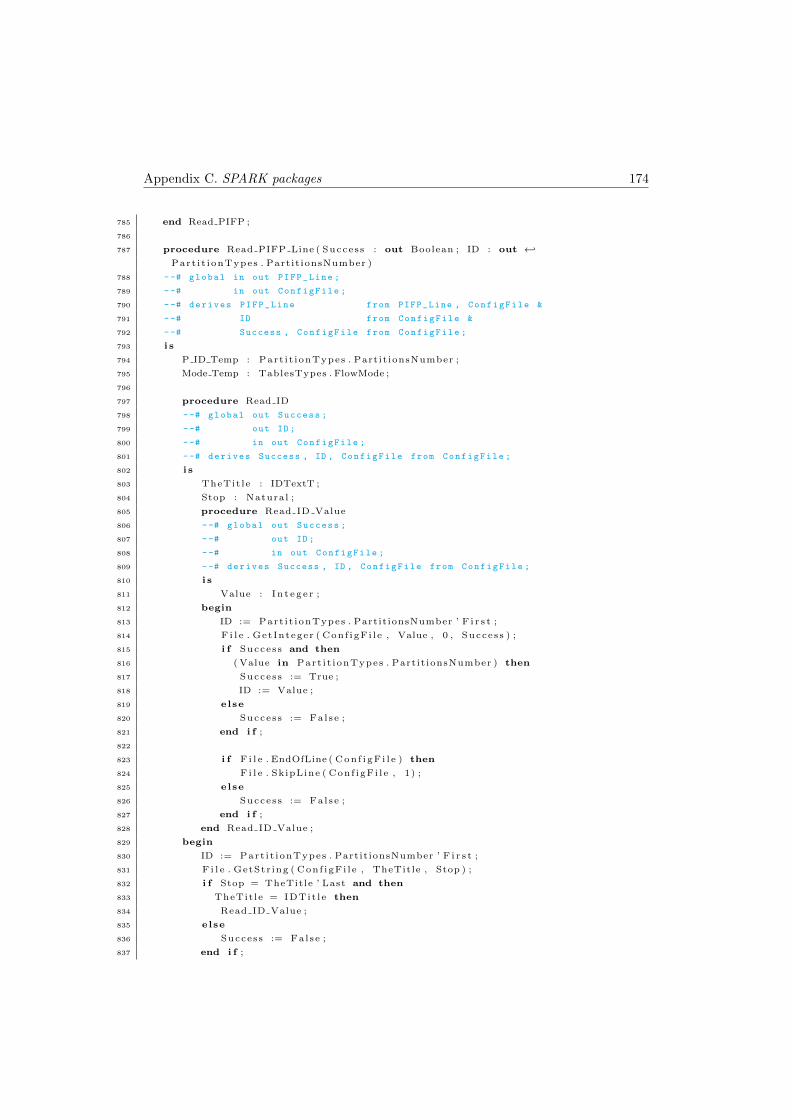
Appendix C. SPARK packages 174
785 end Read PIFP ;
786
787 procedure Read PIFP Line ( Success : out Boolean ; ID : out ←↩
Part i t ionTypes . Partit ionsNumber )
788 --# global in out PIFP_Line ;
789 --# in out ConfigFile ;
790 --# derives PIFP_Line from PIFP_Line , ConfigFile &
791 --# ID from ConfigFile &
792 --# Success , ConfigFile from ConfigFile ;
793 i s
794 P ID Temp : Part i t ionTypes . Partit ionsNumber ;
795 Mode Temp : TablesTypes . FlowMode ;
796
797 procedure Read ID
798 --# global out Success ;
799 --# out ID ;
800 --# in out ConfigFile ;
801 --# derives Success , ID , ConfigFile from ConfigFile ;
802 i s
803 TheTit le : IDTextT ;
804 Stop : Natural ;
805 procedure Read ID Value
806 --# global out Success ;
807 --# out ID ;
808 --# in out ConfigFile ;
809 --# derives Success , ID , ConfigFile from ConfigFile ;
810 i s
811 Value : In t eg e r ;
812 begin
813 ID := Part i t ionTypes . PartitionsNumber ’ F i r s t ;
814 F i l e . GetInteger ( Conf igFi l e , Value , 0 , Success ) ;
815 i f Success and then
816 ( Value in Part i t ionTypes . Partit ionsNumber ) then
817 Success := True ;
818 ID := Value ;
819 else
820 Success := False ;
821 end i f ;
822
823 i f F i l e . EndOfLine ( Con f i gF i l e ) then
824 F i l e . SkipLine ( Conf igFi l e , 1) ;
825 else
826 Success := False ;
827 end i f ;
828 end Read ID Value ;
829 begin
830 ID := Part i t ionTypes . PartitionsNumber ’ F i r s t ;
831 F i l e . GetStr ing ( Conf igFi l e , TheTitle , Stop ) ;
832 i f Stop = TheTitle ’ Last and then
833 TheTit le = IDTit le then
834 Read ID Value ;
835 else
836 Success := False ;
837 end i f ;
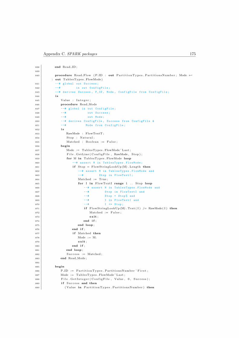
Appendix C. SPARK packages 175
838 end Read ID ;
839
840 procedure Read Flow ( P ID : out Part i t ionTypes . Partit ionsNumber ; Mode ←↩
: out TablesTypes . FlowMode)
841 --# global out Success ;
842 --# in out ConfigFile ;
843 --# derives Success , P_ID , Mode , ConfigFile from ConfigFile ;
844 i s
845 Value : In t eg e r ;
846 procedure Read Mode
847 --# global in out ConfigFile ;
848 --# out Success ;
849 --# out Mode ;
850 --# derives ConfigFile , Success from ConfigFile &
851 --# Mode from ConfigFile ;
852 i s
853 RawMode : FlowTextT ;
854 Stop : Natural ;
855 Matched : Boolean := False ;
856 begin
857 Mode := TablesTypes . FlowMode ’ Last ;
858 F i l e . GetLine ( Conf igFi l e , RawMode , Stop ) ;
859 for M in TablesTypes . FlowMode loop
860 --# assert M in TablesTypes . FlowMode ;
861 i f Stop = FlowStringLookUp (M) . Length then
862 --# assert M in TablesTypes . FlowMode and
863 --# Stop in FlowTextI ;
864 Matched := True ;
865 for I in FlowTextI range 1 . . Stop loop
866 --# assert M in TablesTypes . FlowMode and
867 --# Stop in FlowTextI and
868 --# Stop = Stop % and
869 --# I in FlowTextI and
870 --# I <= Stop ;
871 i f FlowStringLookUp (M) . Text ( I ) /= RawMode( I ) then
872 Matched := False ;
873 exit ;
874 end i f ;
875 end loop ;
876 end i f ;
877 i f Matched then
878 Mode := M;
879 exit ;
880 end i f ;
881 end loop ;
882 Success := Matched ;
883 end Read Mode ;
884
885 begin
886 P ID := Part i t ionTypes . PartitionsNumber ’ F i r s t ;
887 Mode := TablesTypes . FlowMode ’ Last ;
888 F i l e . GetInteger ( Conf igFi l e , Value , 0 , Success ) ;
889 i f Success and then
890 ( Value in Part i t ionTypes . Partit ionsNumber ) then
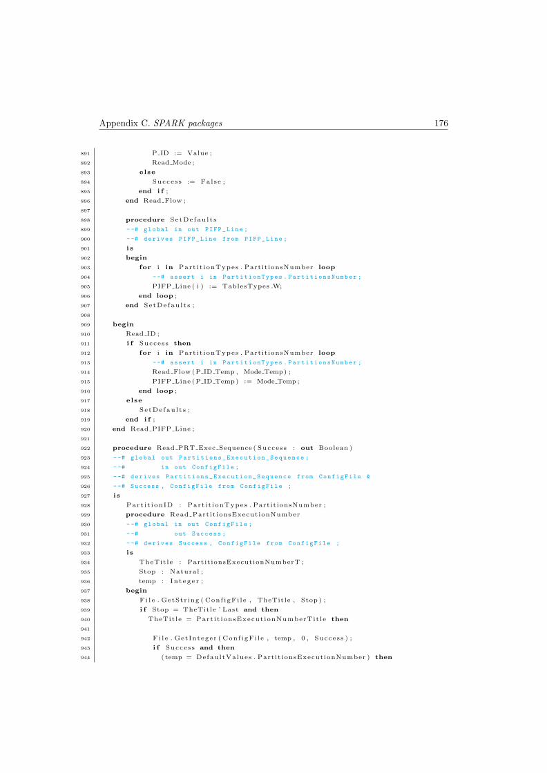
Appendix C. SPARK packages 176
891 P ID := Value ;
892 Read Mode ;
893 else
894 Success := False ;
895 end i f ;
896 end Read Flow ;
897
898 procedure SetDe fau l t s
899 --# global in out PIFP_Line ;
900 --# derives PIFP_Line from PIFP_Line ;
901 i s
902 begin
903 for i in Part i t ionTypes . Partit ionsNumber loop
904 --# assert i in PartitionTypes . PartitionsNumber ;
905 PIFP Line ( i ) := TablesTypes .W;
906 end loop ;
907 end SetDe fau l t s ;
908
909 begin
910 Read ID ;
911 i f Success then
912 for i in Part i t ionTypes . Partit ionsNumber loop
913 --# assert i in PartitionTypes . PartitionsNumber ;
914 Read Flow (P ID Temp , Mode Temp) ;
915 PIFP Line (P ID Temp) := Mode Temp ;
916 end loop ;
917 else
918 SetDe fau l t s ;
919 end i f ;
920 end Read PIFP Line ;
921
922 procedure Read PRT Exec Sequence ( Success : out Boolean )
923 --# global out Partitions_Execution_Sequence ;
924 --# in out ConfigFile ;
925 --# derives Partitions_Execution_Sequence from ConfigFile &
926 --# Success , ConfigFile from ConfigFile ;
927 i s
928 Part i t i onID : Part i t ionTypes . Partit ionsNumber ;
929 procedure Read Partit ionsExecutionNumber
930 --# global in out ConfigFile ;
931 --# out Success ;
932 --# derives Success , ConfigFile from ConfigFile ;
933 i s
934 TheTit le : PartitionsExecutionNumberT ;
935 Stop : Natural ;
936 temp : In t eg e r ;
937 begin
938 F i l e . GetStr ing ( Conf igFi l e , TheTitle , Stop ) ;
939 i f Stop = TheTitle ’ Last and then
940 TheTit le = Part i t ionsExecut ionNumberTit le then
941
942 F i l e . GetInteger ( Conf igFi l e , temp , 0 , Success ) ;
943 i f Success and then
944 ( temp = DefaultValues . Partit ionsExecutionNumber ) then
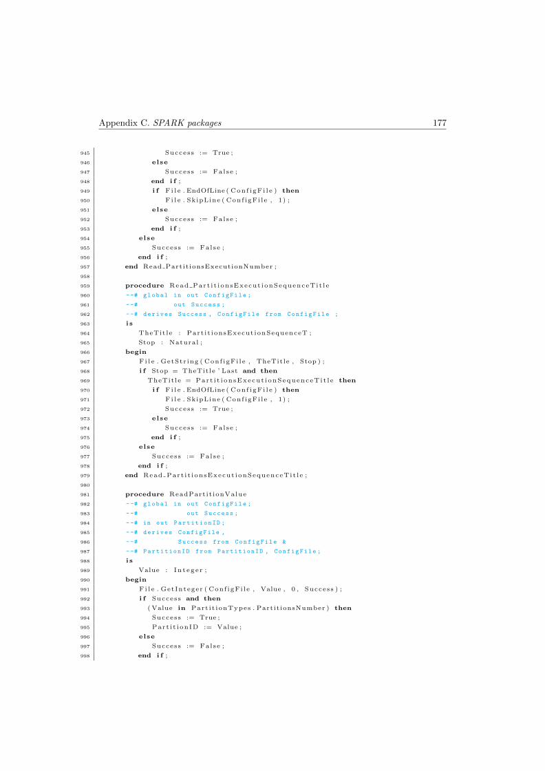
Appendix C. SPARK packages 177
945 Success := True ;
946 else
947 Success := False ;
948 end i f ;
949 i f F i l e . EndOfLine ( Con f i gF i l e ) then
950 F i l e . SkipLine ( Conf igFi l e , 1) ;
951 else
952 Success := False ;
953 end i f ;
954 else
955 Success := False ;
956 end i f ;
957 end Read Partit ionsExecutionNumber ;
958
959 procedure Read Part i t i onsExecut ionSequenceTi t l e
960 --# global in out ConfigFile ;
961 --# out Success ;
962 --# derives Success , ConfigFile from ConfigFile ;
963 i s
964 TheTit le : Part i t ionsExecut ionSequenceT ;
965 Stop : Natural ;
966 begin
967 F i l e . GetStr ing ( Conf igFi l e , TheTitle , Stop ) ;
968 i f Stop = TheTitle ’ Last and then
969 TheTit le = Par t i t i onsExecut i onSequenceT i t l e then
970 i f F i l e . EndOfLine ( Con f i gF i l e ) then
971 F i l e . SkipLine ( Conf igFi l e , 1) ;
972 Success := True ;
973 else
974 Success := False ;
975 end i f ;
976 else
977 Success := False ;
978 end i f ;
979 end Read Part i t i onsExecut ionSequenceTi t l e ;
980
981 procedure ReadPart it ionValue
982 --# global in out ConfigFile ;
983 --# out Success ;
984 --# in out PartitionID ;
985 --# derives ConfigFile ,
986 --# Success from ConfigFile &
987 --# PartitionID from PartitionID , ConfigFile ;
988 i s
989 Value : In t eg e r ;
990 begin
991 F i l e . GetInteger ( Conf igFi l e , Value , 0 , Success ) ;
992 i f Success and then
993 ( Value in Part i t ionTypes . Partit ionsNumber ) then
994 Success := True ;
995 Part i t i onID := Value ;
996 else
997 Success := False ;
998 end i f ;
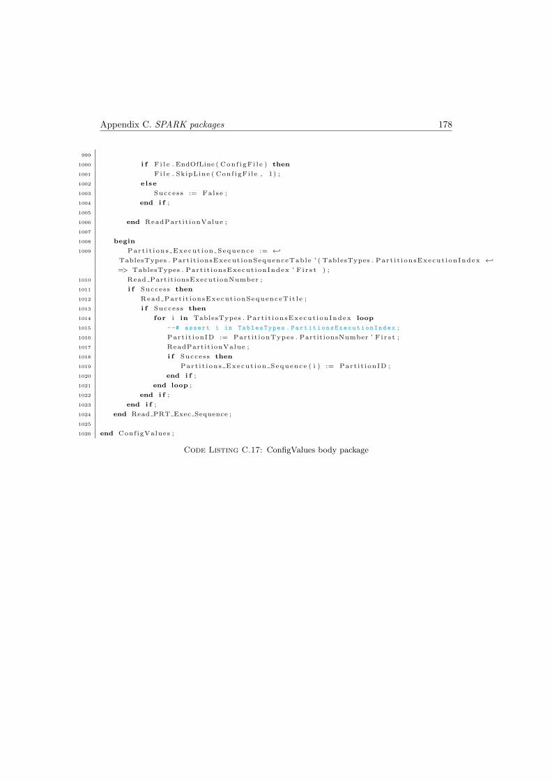
Appendix C. SPARK packages 178
999
1000 i f F i l e . EndOfLine ( Con f i gF i l e ) then
1001 F i l e . SkipLine ( Conf igFi l e , 1) ;
1002 else
1003 Success := False ;
1004 end i f ;
1005
1006 end ReadPart it ionValue ;
1007
1008 begin
1009 Part i t i ons Execut i on Sequence := ←↩
TablesTypes . Part i t ionsExecut ionSequenceTable ’ ( TablesTypes . Par t i t i onsExecut ionIndex ←↩
=> TablesTypes . Part i t ionsExecut ionIndex ’ F i r s t ) ;
1010 Read Partit ionsExecutionNumber ;
1011 i f Success then
1012 Read Part i t i onsExecut ionSequenceTi t l e ;
1013 i f Success then
1014 for i in TablesTypes . Par t i t i onsExecut ionIndex loop
1015 --# assert i in TablesTypes . PartitionsExecutionIndex ;
1016 Part i t i onID := Part i t ionTypes . PartitionsNumber ’ F i r s t ;
1017 ReadPart it ionValue ;
1018 i f Success then
1019 Part i t i ons Execut i on Sequence ( i ) := Part i t i onID ;
1020 end i f ;
1021 end loop ;
1022 end i f ;
1023 end i f ;
1024 end Read PRT Exec Sequence ;
1025
1026 end ConfigValues ;
Code Listing C.17: ConfigValues body package
Appendix D
Example of a configuration file
An example of a valid configuration file is presented in this appendix. In this configu-
ration file, as we can see in the first three lines, the kernel has 3 partitions, it has 20
blocks of memory for communication, and every one is divided in 4. Each partition has
obligatorily 2 processes, as we can see in line number four.
The partition with ID=1, as we can see in between lines twenty and twenty-nine, has
size=350, has a duration=12, and has one process that wants to communicate with the
partition with ID=2, to “Write” and the message size is 5. It has another process to do
“Nothing”. The partition with ID=2, as we can see in between lines six and eighteen,
has size=149, has a duration=3 and has two processes that want to communicate; both
want to communicate with partition ID=1, one is to “Read” being the message size
4, and the other is to “Write” being the message size 1. Finally, the partition with
ID=3, as we can see in between lines thirty-one and thirty-seven, has size=170, has a
duration=11 and both processes are specified to do “Nothing”.
The cycle of execution consists of 4 partitions, and the sequence is respectively, ID=2,
ID=1, ID=2, ID=3, as we can see in between lines thirty-eight and forty-three. The
partition information flow policy, as we can see from line forty-five until de end of the
file, is composed by: the partition ID=1, can communicate with partitions ID=2 and
ID=3 to “Read/Write”; the partition which ID=2 only can communicate with partition
ID=1 to “Read/Write”; and the partition ID=3 can not communicate with any of them.
179
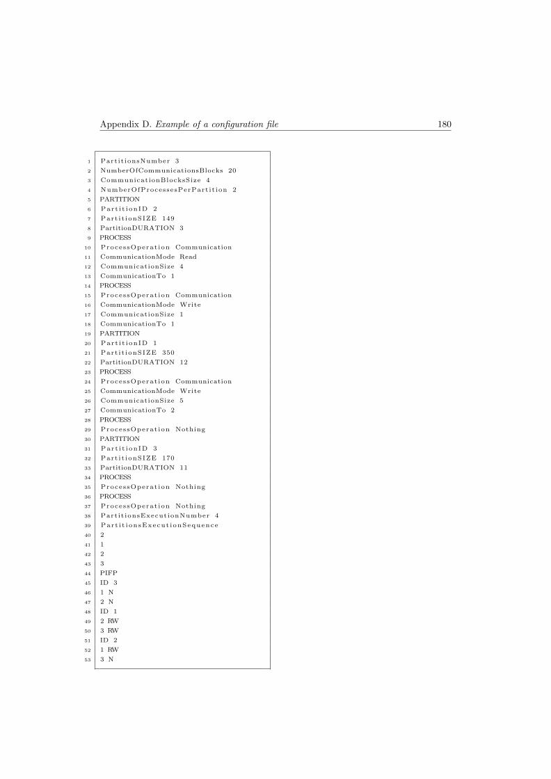
Appendix D. Example of a configuration file 180
1 Partit ionsNumber 3
2 NumberOfCommunicationsBlocks 20
3 CommunicationBlocksSize 4
4 NumberOfProcessesPerPart it ion 2
5 PARTITION
6 Part i t i onID 2
7 Part i t ionSIZE 149
8 PartitionDURATION 3
9 PROCESS
10 ProcessOperat ion Communication
11 CommunicationMode Read
12 CommunicationSize 4
13 CommunicationTo 1
14 PROCESS
15 ProcessOperat ion Communication
16 CommunicationMode Write
17 CommunicationSize 1
18 CommunicationTo 1
19 PARTITION
20 Part i t i onID 1
21 Part i t ionSIZE 350
22 PartitionDURATION 12
23 PROCESS
24 ProcessOperat ion Communication
25 CommunicationMode Write
26 CommunicationSize 5
27 CommunicationTo 2
28 PROCESS
29 ProcessOperat ion Nothing
30 PARTITION
31 Part i t i onID 3
32 Part i t ionSIZE 170
33 PartitionDURATION 11
34 PROCESS
35 ProcessOperat ion Nothing
36 PROCESS
37 ProcessOperat ion Nothing
38 Partit ionsExecutionNumber 4
39 Part i t i onsExecut ionSequence
40 2
41 1
42 2
43 3
44 PIFP
45 ID 3
46 1 N
47 2 N
48 ID 1
49 2 RW
50 3 RW
51 ID 2
52 1 RW
53 3 N