formal analysis of security properties in trusted ... · formal analysis of security properties in...
TRANSCRIPT

Formal Analysis of Security Properties inTrusted Computing Protocols
by
Younes Seifi
Bachelor of Science in Software Engineering (Sharif University of Technology) –1997
Master of Science in Software Engineering (Amir Kabir University ofTechnology) – 2000
Thesis submitted in accordance with the regulations for
the Degree of Doctor of Philosophy
Information Security InstituteFaculty of Science and Engineering
Queensland University of Technology
March 3, 2014


Keywords
Coloured Petri Nets; CPN; CPN/Tools; security analysis; TPM; SKAP; OSAP;
Trusted Computing, ASK-CTL;
i

ii

Abstract
The contributions of this thesis are divided into three different areas. The first
one is introducing a general methodology to create a Coloured Petri Net (CPN)
model of a security protocol. The proposed methodology identifies steps to cre-
ate, validate and verify the model. It describes how the model is created based on
the protocol definition, then suggests approaches to create, simulate and validate
the model faster. A number of well-known approaches such as parameterisation
are included in the methodology to address CPN problems such as state space
explosion.
Our next contribution is identifying security properties relevant to trusted
computing. Applying the CPN model creation methodology, two Trusted Plat-
form Module (TPM) authorisation protocols have been modelled. It is illustrated
how the authentication property can be modelled and analysed in both proto-
cols. Then for a TPM-based Oblivious Transfer (OT) protocol three different
properties have been identified and modelled using CPN.
The last contribution is verification of modelled properties. The Compu-
tational Tree Logic (CTL) is used to verify modelled authorisation protocols
authentication property and three different security properties of an OT proto-
col. The verification step requires expanding the protocol model to include an
intruder. The Dolev-Yao intruder model is used as the most powerful adversary
for analysis. The achievement of all three contributions introduces a method
that can be applied to analyse standard (such as secrecy and authentication)
and TPM related security properties of integrated platforms such as trusted
computing with multiple cooperating sub-platforms.
iii

iv

Contents
Front Matter i
Keywords . . . . . . . . . . . . . . . . . . . . . . . . . . . . . . . . . . i
Abstract . . . . . . . . . . . . . . . . . . . . . . . . . . . . . . . . . . . iii
Table of Contents . . . . . . . . . . . . . . . . . . . . . . . . . . . . . . v
List of Figures . . . . . . . . . . . . . . . . . . . . . . . . . . . . . . . . xi
List of Tables . . . . . . . . . . . . . . . . . . . . . . . . . . . . . . . . xvii
Previously Published Material . . . . . . . . . . . . . . . . . . . . . . . xxi
Acknowledgements . . . . . . . . . . . . . . . . . . . . . . . . . . . . . xxiii
1 Introduction 1
1.1 Research objectives . . . . . . . . . . . . . . . . . . . . . . . . . . 4
1.2 Outline . . . . . . . . . . . . . . . . . . . . . . . . . . . . . . . . . 4
2 Background 7
2.1 Security Properties . . . . . . . . . . . . . . . . . . . . . . . . . . 8
2.2 Formal methods . . . . . . . . . . . . . . . . . . . . . . . . . . . . 9
2.2.1 Dolev-Yao intruder model . . . . . . . . . . . . . . . . . . 11
2.3 Formal security analysis tools . . . . . . . . . . . . . . . . . . . . 12
2.3.1 The Naval Research Laboratory Protocol Analyser . . . . 13
2.3.2 BAN logic . . . . . . . . . . . . . . . . . . . . . . . . . . . 13
2.3.3 GNY logic . . . . . . . . . . . . . . . . . . . . . . . . . . . 14
2.3.4 BGNY logic . . . . . . . . . . . . . . . . . . . . . . . . . . 14
2.3.5 Brutus . . . . . . . . . . . . . . . . . . . . . . . . . . . . . 14
2.3.6 Interrogator analysis tool . . . . . . . . . . . . . . . . . . . 15
2.3.7 AVISPA tool . . . . . . . . . . . . . . . . . . . . . . . . . 15
2.3.8 ProVerif tool . . . . . . . . . . . . . . . . . . . . . . . . . 16
2.3.9 The CryptoVerif tool . . . . . . . . . . . . . . . . . . . . . 16
v

2.3.10 The Scyther tool . . . . . . . . . . . . . . . . . . . . . . . 16
2.3.11 Hermes tool . . . . . . . . . . . . . . . . . . . . . . . . . . 17
2.3.12 SHVT . . . . . . . . . . . . . . . . . . . . . . . . . . . . . 17
2.3.13 Coloured Petri Nets . . . . . . . . . . . . . . . . . . . . . . 18
2.3.14 Summary of analysis tools . . . . . . . . . . . . . . . . . . 19
2.4 CPN modelling . . . . . . . . . . . . . . . . . . . . . . . . . . . . 21
2.4.1 CPN/Tools . . . . . . . . . . . . . . . . . . . . . . . . . . 23
2.4.2 Modelling a sample protocol . . . . . . . . . . . . . . . . . 23
2.4.3 State space analysis . . . . . . . . . . . . . . . . . . . . . . 26
2.4.4 Computational Tree Logic (CTL) . . . . . . . . . . . . . . 27
The CPN/Tools ASK-CTL . . . . . . . . . . . . . . . . . . 28
2.4.5 Using CPN to model security protocols . . . . . . . . . . . 29
2.5 Trusted Computing (TC) . . . . . . . . . . . . . . . . . . . . . . . 30
2.5.1 Trusted Computing Group (TCG) . . . . . . . . . . . . . . 30
2.5.2 Transitive Trust . . . . . . . . . . . . . . . . . . . . . . . . 31
2.5.3 Trusted Platform Module (TPM) . . . . . . . . . . . . . . 33
2.5.4 Design goals of the TPM . . . . . . . . . . . . . . . . . . . 34
2.5.5 TPM command validation protocols . . . . . . . . . . . . . 35
How command validation works . . . . . . . . . . . . . . . 36
Protocols that support command validation . . . . . . . . 38
Object-Independent Authorisation Protocol (OIAP) . . . . 38
Object-Specific Authorisation Protocol (OSAP) . . . . . . 39
Authorisation Data Insertion Protocol (ADIP) . . . . . . . 39
Authorisation Data Change Protocol (ADCP) . . . . . . . 40
Asymmetric Authorisation Change Protocol (AACP) . . . 40
2.5.6 Introducing some programming interfaces to TPM . . . . . 41
2.6 Attacks against TPM and its related components . . . . . . . . . 42
2.6.1 The off-line dictionary attack on TCG TPM . . . . . . . . 43
2.6.2 Software, reset and timing attacks against TPM . . . . . . 43
Software attacks . . . . . . . . . . . . . . . . . . . . . . . 43
Reset attack . . . . . . . . . . . . . . . . . . . . . . . . . . 43
Timing attack . . . . . . . . . . . . . . . . . . . . . . . . . 44
2.6.3 Attacks based on composition of insecure protocol . . . . . 45
2.6.4 Attacks against trusted platform communications . . . . . 45
2.6.5 Attacks against TSS . . . . . . . . . . . . . . . . . . . . . 46
vi

2.6.6 Attacks against TPM using chosen sequence of commands 46
2.6.7 Replay attack in TCG specification . . . . . . . . . . . . . 47
2.6.8 Attack against shared authorisation data in TCG TPM . . 47
2.7 Summary . . . . . . . . . . . . . . . . . . . . . . . . . . . . . . . 48
3 Using formal methods in TPM analysis 51
3.1 Needham-Schroeder Public Key (NSPK) protocol . . . . . . . . . 52
3.2 Creating Al-Azzoni’s NSPK CPN model . . . . . . . . . . . . . . 53
3.2.1 Al-Azzoni NSPK CPN model creation . . . . . . . . . . . 53
3.2.2 modelling the Al-Azzoni NSPK intruder . . . . . . . . . . 58
3.2.3 Including the intruder in the Al-Azzoni NSPK model . . . 59
3.2.4 Discussion of Al-Azzoni’s NSPK model . . . . . . . . . . . 63
3.3 Proposal of a methodology to CPN model design . . . . . . . . . 68
3.3.1 Identifying communication principals . . . . . . . . . . . . 69
3.3.2 Identifying messages sent and received by principals . . . . 70
3.3.3 Designing CPN model of each protocol exchange . . . . . . 71
3.3.4 Designing places and transitions of each module . . . . . . 72
3.3.5 Validating model . . . . . . . . . . . . . . . . . . . . . . . 75
3.3.6 Designing, validating and integrating intruder model . . . 76
Intruder database . . . . . . . . . . . . . . . . . . . . . . . 77
Intruder model design . . . . . . . . . . . . . . . . . . . . 77
Intruder transitions guard . . . . . . . . . . . . . . . . . . 78
Intruder extra places (enabler places) . . . . . . . . . . . . 78
Intruder initial values and special requirements . . . . . . 78
Intruder model test and integration . . . . . . . . . . . . . 79
3.3.7 Verifying model using ASK-CTL . . . . . . . . . . . . . . 82
3.3.8 Adding configurability to the model (if required) . . . . . . 82
3.4 Recommendations to create CPN model . . . . . . . . . . . . . . 93
3.5 Discussion of general modelling methodology . . . . . . . . . . . . 94
3.6 Summary . . . . . . . . . . . . . . . . . . . . . . . . . . . . . . . 95
4 Analysis of two TPM protocols 97
4.1 Applied approaches to model OSAP and SKAP . . . . . . . . . . 98
4.1.1 Modelling and verification of authentication property . . . 98
4.1.2 Intruder model and database . . . . . . . . . . . . . . . . . 99
4.1.3 Sequence token mechanism . . . . . . . . . . . . . . . . . . 100
vii

4.1.4 Parameterisation . . . . . . . . . . . . . . . . . . . . . . . 101
Using parameterisation to divide state space . . . . . . . . 101
Creating a configurable model . . . . . . . . . . . . . . . . 102
4.1.5 Error-discovery mechanism . . . . . . . . . . . . . . . . . . 102
4.2 Modelling OSAP . . . . . . . . . . . . . . . . . . . . . . . . . . . 103
4.2.1 OSAP protocol description . . . . . . . . . . . . . . . . . . 103
4.2.2 OSAP CPN model . . . . . . . . . . . . . . . . . . . . . . 106
4.2.3 OSAP intruder model . . . . . . . . . . . . . . . . . . . . 110
4.2.4 Authentication property verification in the OSAP model . 110
4.2.5 Discussion of OSAP model . . . . . . . . . . . . . . . . . . 112
4.3 Modelling SKAP . . . . . . . . . . . . . . . . . . . . . . . . . . . 114
4.3.1 SKAP protocol description . . . . . . . . . . . . . . . . . . 115
4.3.2 SKAP CPN model . . . . . . . . . . . . . . . . . . . . . . 117
4.3.3 SKAP intruder model . . . . . . . . . . . . . . . . . . . . 120
4.3.4 Authentication property verification in the SKAP model . 120
4.3.5 Discussion of SKAP model . . . . . . . . . . . . . . . . . . 123
4.4 Summary . . . . . . . . . . . . . . . . . . . . . . . . . . . . . . . 125
5 Security properties analysis in a TPM-based protocol 127
5.1 Simple OT using TPM . . . . . . . . . . . . . . . . . . . . . . . . 128
5.2 Modelling simple oblivious transfer protocol . . . . . . . . . . . . 130
5.2.1 Intruder model . . . . . . . . . . . . . . . . . . . . . . . . 131
5.3 Modelling simple OT protocol using CPN . . . . . . . . . . . . . 133
5.4 Protocol properties verification using ASK-CTL . . . . . . . . . . 135
5.4.1 Verification of first protocol property (secrecy) . . . . . . . 136
5.4.2 Verification of second protocol property . . . . . . . . . . . 137
5.4.3 Verification of third protocol property . . . . . . . . . . . . 138
5.5 Discussion . . . . . . . . . . . . . . . . . . . . . . . . . . . . . . . 142
5.6 Summary . . . . . . . . . . . . . . . . . . . . . . . . . . . . . . . 142
6 Conclusion and future work 145
6.1 Summary . . . . . . . . . . . . . . . . . . . . . . . . . . . . . . . 145
6.2 Limitations . . . . . . . . . . . . . . . . . . . . . . . . . . . . . . 146
6.3 Future work . . . . . . . . . . . . . . . . . . . . . . . . . . . . . . 147
viii

A Appendix: OSAP CPN model 149
A.1 User substitution transitions . . . . . . . . . . . . . . . . . . . . . 156
A.1.1 Modelling TPM OSAP(pkh, no osap) sub. transition . . . . 156
A.1.2 Modelling ‘Process TPM OSAP Response’ sub. transition 157
A.1.3 Modelling ‘Create Shared Secret User’ sub. transition 158
A.1.4 Modelling TPM CreateWrapKey(...) sub. transition . . . 158
A.2 Intruder substitution transitions . . . . . . . . . . . . . . . . . . . 164
A.2.1 Modelling Intruder 1 sub. transition . . . . . . . . . . . . 164
A.2.2 Modelling Intruder 2 sub. transition . . . . . . . . . . . . 167
A.2.3 Modelling Intruder 3 sub. transition . . . . . . . . . . . 168
A.2.4 Modelling Intruder 4 sub. transition . . . . . . . . . . . . 170
A.3 TPM substitution transitions in OSAP . . . . . . . . . . . . . . . 175
A.3.1 Modelling ‘Process TPM OSAP’ sub. transition . . . . . . 175
A.3.2 Modelling ‘Send TPM OSAP Response’ sub. transition . . 176
A.3.3 Modelling ‘Create Shared Secret TPM’ sub. transition . 177
A.3.4 Modelling ‘Process TPM CreateWrapKey message’ . . . . 178
A.3.5 Modelling ‘Send TPM CreateWrapKey Response’ . . . . . 178
B Appendix: SKAP CPN model 181
B.1 Intruder substitution transitions in SKAP . . . . . . . . . . . . . 189
B.1.1 The ‘I1 frd’ functionality . . . . . . . . . . . . . . . . . 191
B.1.2 The ‘I1 crt’ functionality . . . . . . . . . . . . . . . . . 192
B.1.3 The ‘Intruder 2’ functionality . . . . . . . . . . . . . . . 192
B.1.4 The I2 crt functionality . . . . . . . . . . . . . . . . . . . 193
B.1.5 The I2 frd functionality . . . . . . . . . . . . . . . . . . . 194
B.1.6 The ‘Intruder 3’ functionality . . . . . . . . . . . . . . . 195
B.1.7 The I3 frd functionality . . . . . . . . . . . . . . . . . . . 195
B.1.8 The I3 crt functionality . . . . . . . . . . . . . . . . . . . 195
B.1.9 The I3 crt crtwk functionality . . . . . . . . . . . . . . . 196
B.1.10 The I3 crt hmac functionality . . . . . . . . . . . . . . . . 196
B.1.11 The I3 e newauth functionality . . . . . . . . . . . . . . . 197
B.1.12 The I k1 k2 functionality . . . . . . . . . . . . . . . . . . 197
B.1.13 The ‘Intruder 4’ functionality . . . . . . . . . . . . . . . 197
B.1.14 The I4 frd functionality . . . . . . . . . . . . . . . . . . . 197
B.1.15 The ‘I4 crt’ functionality . . . . . . . . . . . . . . . . . 198
B.1.16 The ‘I4 crt hmac’ functionality . . . . . . . . . . . . . . 198
ix

B.1.17 The ‘I4 crt ne1’ functionality . . . . . . . . . . . . . . . 198
B.1.18 The ‘I4 keyblob’ functionality . . . . . . . . . . . . . . . 198
B.2 User substitution transitions in SKAP . . . . . . . . . . . . . . . 210
B.2.1 The U1 functionality . . . . . . . . . . . . . . . . . . . . . 210
B.2.2 The U2 functionality . . . . . . . . . . . . . . . . . . . . . 211
B.2.3 The Ukeys functionality . . . . . . . . . . . . . . . . . . . 211
B.2.4 The U3 functionality . . . . . . . . . . . . . . . . . . . . . 212
B.2.5 The U4 functionality . . . . . . . . . . . . . . . . . . . . . 213
B.3 TPM substitution transitions in SKAP . . . . . . . . . . . . . . . 215
B.3.1 The T1 functionality . . . . . . . . . . . . . . . . . . . . . 216
B.3.2 The T2 functionality . . . . . . . . . . . . . . . . . . . . . 217
B.3.3 The Tkeys functionality . . . . . . . . . . . . . . . . . . . 218
B.3.4 The T3 functionality . . . . . . . . . . . . . . . . . . . . . 218
B.3.5 The T4 functionality . . . . . . . . . . . . . . . . . . . . . 220
C Appendix: Oblivious Transfer Protocol CPN model 221
C.0.6 Colour set definition . . . . . . . . . . . . . . . . . . . . . 221
C.0.7 CPN model pages . . . . . . . . . . . . . . . . . . . . . . . 227
Bibliography 243
Index 256
x

List of Figures
2.1 Sample of a communication protocol . . . . . . . . . . . . . . . . 25
2.2 The CPN model of a simple communication protocol . . . . . . . 25
2.3 The CPN model simple protocol with an initial marking . . . . . 26
2.4 The CPN model of a simple communication protocol in CPN/Tools 26
2.5 Transitive trust applied to system boot from a static root of trust(from [62]) 32
2.6 The TPM component architecture (from [62]) . . . . . . . . . . . 33
2.7 The command validation sessions and end points . . . . . . . . . 37
2.8 The OIAP sequence . . . . . . . . . . . . . . . . . . . . . . . . . . 39
2.9 The object creation using ADIP . . . . . . . . . . . . . . . . . . . 40
2.10 Updating child authorisation data using ADCP . . . . . . . . . . 41
2.11 The trusted boot process [114] . . . . . . . . . . . . . . . . . . . . 44
3.1 The Needham-Schroeder public key authentication protocol . . . . 52
3.2 An attack against NSPK authentication protocol . . . . . . . . . 52
3.3 The CPN model of NSPK without intruder . . . . . . . . . . . . . 54
3.4 The colour sets, variables and functions of NSPK model without
intruder . . . . . . . . . . . . . . . . . . . . . . . . . . . . . . . . 55
3.5 The sub-module of Entity A . . . . . . . . . . . . . . . . . . . . . 56
3.6 The sub-module of Entity B . . . . . . . . . . . . . . . . . . . . . 57
3.7 The function of checking authentication property of NSPK protocol 58
3.8 The sub-module of intruder . . . . . . . . . . . . . . . . . . . . . 59
3.9 The colour sets, variables and functions of NSPK model with in-
truder . . . . . . . . . . . . . . . . . . . . . . . . . . . . . . . . . 60
3.10 The NSPK protocol with intruder . . . . . . . . . . . . . . . . . . 61
3.11 The modules of intruder substitution transition . . . . . . . . . . 62
3.12 The intruder module of substitution transition T1 in Figure 3.11 . 62
3.13 The intruder module of substitution transition T2 in Figure 3.11 . 63
3.14 The intruder module of substitution transition T3 in Figure 3.11 . 64
xi

3.15 The CPN model of Entity A used for analysis . . . . . . . . . . . 65
3.16 The CPN model of Entity B used for analysis . . . . . . . . . . . 65
3.17 The authentication function used to check auth. property of NSPK 66
3.18 The running AuthViolation2 function and node 9521 occurrence
graph . . . . . . . . . . . . . . . . . . . . . . . . . . . . . . . . . . 66
3.19 The bindings of occurrence graph of Figure 3.18 . . . . . . . . . . 67
3.20 The messages sequence based on the bindings of Figure 3.19 . . . 67
3.21 The sample protocol . . . . . . . . . . . . . . . . . . . . . . . . . 69
3.22 The message fields of sample protocol shown in Figure 3.21 . . . . 71
3.23 The list of Figure 3.22 CPN model colour sets . . . . . . . . . . . 72
3.24 The list of CPN model colour sets . . . . . . . . . . . . . . . . . . 72
3.25 The sample protocol without intruder . . . . . . . . . . . . . . . . 73
3.26 The first process of principal A (pa1 page in Figure 3.25) . . . . . 74
3.27 The com. channel of exchange one (COMMCHL1a page) . . . . . 74
3.28 The first process of principal B (pb1 page) . . . . . . . . . . . . . 75
3.29 The second process of principal B (pb2 page) . . . . . . . . . . . . 76
3.30 The com. channel of exchange two (COMMCHL2a page) . . . . . 76
3.31 The second process of principal A (pa2 page) . . . . . . . . . . . . 77
3.32 The sample protocol with intruder . . . . . . . . . . . . . . . . . . 79
3.33 The ample protocol with intruder colour sets and variables . . . . 80
3.34 The first process of principal A in the sample protocol with the
intruder (pa1 page) . . . . . . . . . . . . . . . . . . . . . . . . . . 81
3.35 The second process of principal A in the sample protocol with the
intruder (pa2 page) . . . . . . . . . . . . . . . . . . . . . . . . . . 82
3.36 The first process of principal B in the sample protocol with the
intruder (pb1 page) . . . . . . . . . . . . . . . . . . . . . . . . . . 83
3.37 The second process of principal B in the sample protocol with the
intruder (pb2 page) . . . . . . . . . . . . . . . . . . . . . . . . . . 84
3.38 The intruder process of exchange one in the sample protocol (int1
page ) . . . . . . . . . . . . . . . . . . . . . . . . . . . . . . . . . 85
3.39 Forwarding the stored message sub-process in the intruder one
(i1frd page) . . . . . . . . . . . . . . . . . . . . . . . . . . . . . 86
3.40 Creating the new message sub-process in ‘intruder 1’ (i1crt
page) . . . . . . . . . . . . . . . . . . . . . . . . . . . . . . . . . . 86
xii

3.41 The intruder process of exchange two in the sample protocol (int2
page) . . . . . . . . . . . . . . . . . . . . . . . . . . . . . . . . . . 87
3.42 Forwarding the stored message sub-process in intruder two (i2frd
page) . . . . . . . . . . . . . . . . . . . . . . . . . . . . . . . . . . 87
3.43 Creating new message sub-process in the ‘intruder 2’ (i2crt
page) . . . . . . . . . . . . . . . . . . . . . . . . . . . . . . . . . . 88
3.44 New declared colour sets and values for the sample configurable
model . . . . . . . . . . . . . . . . . . . . . . . . . . . . . . . . . 88
3.45 The required guard for the first transition . . . . . . . . . . . . . 88
3.46 The configurable model of sample protocol with the intruder . . . 88
3.47 The colour sets of configurable model . . . . . . . . . . . . . . . . 89
3.48 The first process of principal A in the configurable model (pa1 page) 89
3.49 The second process of principal A in the configurable model (pa2
page) . . . . . . . . . . . . . . . . . . . . . . . . . . . . . . . . . . 90
3.50 The first process of principal B in the configurable model (pb1 page) 90
3.51 The second process of principal B in the configurable model (pb2
page) . . . . . . . . . . . . . . . . . . . . . . . . . . . . . . . . . . 91
3.52 The com. channel of first exchange in the configurable model . . . 91
3.53 The com. channel of second exchange in the configurable model . 91
3.54 The first intruder of the configurable model . . . . . . . . . . . . 92
3.55 The second intruder of the configurable model . . . . . . . . . . . 92
3.56 The sample protocol with intruder while intruders have cooperations 94
4.1 The sent message is changed by the intruder . . . . . . . . . . . . 100
4.2 The intruder has bypassed receiver . . . . . . . . . . . . . . . . . 100
4.3 The error-discovery mechanism . . . . . . . . . . . . . . . . . . . 103
4.4 The OSAP sequence diagram . . . . . . . . . . . . . . . . . . . . 104
4.5 The main page of OSAP protocol CPN model . . . . . . . . . . . 109
4.6 The result of OSAP ASK-CTL formula . . . . . . . . . . . . . . . 112
4.7 The page U2 module of the OSAP CPN model . . . . . . . . . . . 113
4.8 The SKAP sequence diagram . . . . . . . . . . . . . . . . . . . . 115
4.9 The used constants in communication channel mode . . . . . . . . 119
4.10 The main page of SKAP protocol CPN model . . . . . . . . . . . 119
4.11 The main CPN page of SKAP protocol User principal . . . . . . . 120
4.12 The main page of SKAP protocol TPM principal CPN model . . 121
4.13 The main page of SKAP protocol intruders CPN model . . . . . . 122
xiii

4.14 The result of SKAP ASK-CTL formula . . . . . . . . . . . . . . . 123
4.15 The page of u1 module of the SKAP CPN model . . . . . . . . . 124
5.1 The simple oblivious transfer protocol steps . . . . . . . . . . . . 130
5.2 The simple OT protocol with more detail for CPN implementation 131
5.3 The simple OT protocol diagram with intruder capabilities . . . . 132
5.4 The intruder actions to open secrets . . . . . . . . . . . . . . . . . 132
5.5 The intruder actions to open secrets using PCR extension . . . . . 133
5.6 The intruder actions to open secrets using decryption . . . . . . . 133
5.7 The main CPN page of the simple OT protocol . . . . . . . . . . 134
5.8 The ASK-CTL formula of 1st condition (secrecy property) . . . . 136
5.9 The result of ASK-CTL formula for the first condition . . . . . . 137
5.10 The ML code for the second condition ASK-CTL formula . . . . . 138
5.11 The result of ASK-CTL formula for the second condition . . . . . 139
5.12 The ML code for the third condition ASK-CTL formula . . . . . . 141
5.13 The result of ASK-CTL formula for the third condition . . . . . . 141
A.1 The colorsets of OSAP model . . . . . . . . . . . . . . . . . . . . 154
A.2 The list of OSAP model variables . . . . . . . . . . . . . . . . . . 155
A.3 The initial value of the intruder database . . . . . . . . . . . . . . 155
A.4 The TPM OSAP(pkh, no osap) (page U1) CPN model . . . . . . . 157
A.5 The ‘Process TPM OSAP Response’ (page U2) CPN model. . . . 158
A.6 The ‘Create Shared Secret User’ (page U3) CPN model . . . 159
A.7 The TPM CreateWrapKey(...) (page U4) CPN model. . . . . . . 161
A.8 The Create XOR (page U4 1) CPN model. . . . . . . . . . . . . . 162
A.9 The ‘Prepare TPM CreateWrapKey’ (page U4 2) CPN model . . 162
A.10 The ‘Compute HMAC’ (page U4 3) CPN model . . . . . . . . . . . 162
A.11 The ‘Process TPM CreateWrapKey(...) Response’ (page U5)
CPN model . . . . . . . . . . . . . . . . . . . . . . . . . . . . . . 163
A.12 The Intruder 1(page Int 1) CPN model . . . . . . . . . . . . . . 165
A.13 The function fakedxchg1() details. . . . . . . . . . . . . . . . . . 166
A.14 The function fakedxchg2() details . . . . . . . . . . . . . . . . . 168
A.15 The Intruder 2 (page Int 2) CPN model . . . . . . . . . . . . . 169
A.16 The Intruder 3 (page Int 3) CPN model . . . . . . . . . . . . . 172
A.17 The Int 3 1 page CPN model . . . . . . . . . . . . . . . . . . . . 173
A.18 The ML-Function of fakedxchg3(...) . . . . . . . . . . . . . . . 173
xiv

A.19 The Intruder 4 (page Int 4) CPN model . . . . . . . . . . . . . 174
A.20 The ML-Function of fakedxchg4(...) . . . . . . . . . . . . . . . 174
A.21 The ‘Process TPM OSAP’ (page T1) substitution transition . . . 176
A.22 The ‘Send TPM OSAP Response’(page T2) substitution transition 177
A.23 The ‘Create Shared Secret TPM’ (page T3) substitution tran-
sition . . . . . . . . . . . . . . . . . . . . . . . . . . . . . . . . . . 177
A.24 The ‘Process TPM CreateWrapKey message’ (page T4) CPN model179
A.25 The ‘Send TPM CreateWrapKey Response’ (page T5) CPN model 180
B.1 The list of SKAP CPN model colour sets . . . . . . . . . . . . . . 187
B.2 The list of SKAP model variables . . . . . . . . . . . . . . . . . . 188
B.3 The CPN model of ‘Intruder 1’ page . . . . . . . . . . . . . . . 190
B.4 The CPN model of I1 frd page . . . . . . . . . . . . . . . . . . . 191
B.5 The CPN model of I1 crt page . . . . . . . . . . . . . . . . . . . 192
B.6 The CPN model of ‘Intruder 2’ page . . . . . . . . . . . . . . . 194
B.7 The CPN model of I2 crt page . . . . . . . . . . . . . . . . . . . 199
B.8 The CPN model of I2 frd page . . . . . . . . . . . . . . . . . . . 200
B.9 The CPN model of SKAP ‘Intruder 3’ page . . . . . . . . . . . 201
B.10 The CPN model of SKAP I3 frd page . . . . . . . . . . . . . . . 202
B.11 The CPN model of SKAP I3 crt page . . . . . . . . . . . . . . . 202
B.12 The CPN model of SKAP I3 crt crtwk page . . . . . . . . . . . 203
B.13 The CPN model of SKAP I3 crt hmac page . . . . . . . . . . . . 204
B.14 The CPN model of SKAP I3 e newauth page . . . . . . . . . . . 204
B.15 The CPN model of SKAP I k1 k2 page . . . . . . . . . . . . . . . 205
B.16 The CPN model of SKAP ‘Intruder 4’ page . . . . . . . . . . . 205
B.17 The SKAP model ML-Functions . . . . . . . . . . . . . . . . . . . 206
B.18 The CPN model of SKAP I4 frd page . . . . . . . . . . . . . . . 207
B.19 The CPN model of SKAP I4 crt page . . . . . . . . . . . . . . . 207
B.20 The CPN model of SKAP I4 crt hmac page . . . . . . . . . . . . 208
B.21 The CPN model of SKAP I4 crt ne1 page . . . . . . . . . . . . . 209
B.22 The CPN model of SKAP I4 keyblob page . . . . . . . . . . . . 209
B.23 The CPN model of SKAP U1 page . . . . . . . . . . . . . . . . . 211
B.24 The CPN model of SKAP U2 page . . . . . . . . . . . . . . . . . 212
B.25 The CPN model of SKAP UKeys page . . . . . . . . . . . . . . . 213
B.26 The CPN model of SKAP U3 page . . . . . . . . . . . . . . . . . 214
B.27 The CPN model of SKAP U4 page . . . . . . . . . . . . . . . . . 215
xv

B.28 The CPN model of SKAP T1 page . . . . . . . . . . . . . . . . . 216
B.29 The CPN model of SKAP T2 page . . . . . . . . . . . . . . . . . 217
B.30 The CPN model of SKAP Tkeys page . . . . . . . . . . . . . . . 218
B.31 The CPN model of SKAP T3 page . . . . . . . . . . . . . . . . . 219
B.32 The CPN model of SKAP T4 page . . . . . . . . . . . . . . . . . 220
C.1 The list of model colour sets . . . . . . . . . . . . . . . . . . . . . 222
C.2 The list of the TPM secrecy model variables . . . . . . . . . . . . 227
C.3 The first page of the Bob CPN model . . . . . . . . . . . . . . . . 227
C.4 The first page of the TPM CPN model . . . . . . . . . . . . . . . 228
C.5 The second page of the Bob CPN model . . . . . . . . . . . . . . 229
C.6 The Alice CPN page . . . . . . . . . . . . . . . . . . . . . . . . . 230
C.7 The third page of the Bob CPN model . . . . . . . . . . . . . . . 231
C.8 The extend PCR page . . . . . . . . . . . . . . . . . . . . . . . . 232
C.9 The Bob page to open first secret by PCR extension . . . . . . . . 233
C.10 The BS1 TPM2 page to manage Bob sent commands to open S1 . . 233
C.11 The Bob page to open second secret by PCR extension . . . . . . 234
C.12 The BS2 TPM2 page to manage Bob sent commands to open S2 . . 234
C.13 The IC1S1-ex sub-page of page Extnd-PCR . . . . . . . . . . . . . 235
C.14 The IC1 TPM2 sub-page . . . . . . . . . . . . . . . . . . . . . . . 236
C.15 The IC1S2 ex sub-page of page Extnd PCR . . . . . . . . . . . . . 237
C.16 The IC1 TPM2 sub-page . . . . . . . . . . . . . . . . . . . . . . . 237
C.17 The IC2S2 ex sub-page of page Extnd PCR . . . . . . . . . . . . . 238
C.18 The IC2 TPM2 sub-page . . . . . . . . . . . . . . . . . . . . . . . 239
C.19 The IC2S1-ex sub-page of page Extnd-PCR . . . . . . . . . . . . . 240
C.20 The IC2 TPM3 sub-page . . . . . . . . . . . . . . . . . . . . . . . . 240
C.21 The CPN model of Dec sec substitution transition in Main page . 241
C.22 The detail of model functions . . . . . . . . . . . . . . . . . . . . 241
C.23 The CPN model of sec err ex page . . . . . . . . . . . . . . . . 242
xvi

List of Tables
2.1 Advantages of the studied security analysis tools . . . . . . . . . . 20
2.2 Disadvantages of the studied security analysis tools . . . . . . . . 20
3.1 The sequence token value at the end of each substitution transition 84
xvii

xviii

Declaration
The work contained in this thesis has not been previously submitted for a degree
or a diploma at any higher education institution. To the best of my knowledge
and belief, the thesis contains no material previously published or written by
another person except where due reference is made.
xix
QUT Verified Signature

xx
Previously Published Material
The following papers have been published or presented, and contain material
based on the content of this thesis.
1- Seifi, Y., Suriadi, S., Foo, E. and Boyd, C. Analysis of Object-Specific
Authorisation Protocol (OSAP) using Coloured Petri Nets, AISC2012.
2- Seifi, Y. Suriadi, S., Foo, E. and Boyd, C. Security properties analysis in a
TPM-based protocol, International Journal of Security and Networks, Accepted
for publication.
3- Seifi, Y. Suriadi, S., Foo, E. and Boyd, C. Analysis of two Authoriza-
tion Protocols using Coloured Petri Nets, International Journal of Information
Security, Accepted for publication.
xxi

xxii

Acknowledgements
I may not have reached this point in my studies without supoort and inspiration
offered to me by my supervisors. I am deeply grateful to them and would like to
express my thanks to my principle supervisor Dr. Ernest Foo and my associate
supervisors Prof. Colin Boyd and Dr. Suriadi Suriadi.
I wish to thank Dr. Leonie Simpson and Dr. Moe Wynn for being in the
internal panel of my final seminar. I also thank Dr. Jason Reid for being in the
panel of my confirmation seminar. I thank all three external reviewers who have
reviewed my work.
In addition, my time in Information Security Institute (ISI) and level 9 of
Margaret street building has been so nice and unique. I had a chance to find
new friends from various countries and cultures whose support and friendship
helped me work better. I would like to thank: Mr. Ali Alhamdan, Dr. Bandar
Alhaqbani, Ms. Chai Wen Chuah, Ms. Christine Yates, Ms. Elham Abdi, Dr.
Farzad Salim, Mr. Fayez Alqahtani, Dr. Hani Alzaid, Mr. Hashem Almakrami,
Dr. Ian Stoodley, Mr. IS, Dr. Kenneth Radke, Dr. Khamsum Kinley, Dr.
Long Ngo, Mr. Raphael Amoah, Mr. Reza Hassanzadeh, Ms. Roheena Khan,
Mr. Sajal Bhatia, Mr. Sirous Panahi, Mr. Nishchal Kush. Special thanks to Ms.
Elizabeth Hansford and Ms. Christine Kincaid for their administrative assistance
and Mr. Gleb Sechenov for his technical help.
I would like to thank all my Iranian friends in Brisbane and Gold Coast for
their friendship and help. I started my PhD when my son was only 6 months.
Through the journey of my PhD his smiles and cute face helped me to forget
all difficulties and be full of energy to continue my research. Thanks a lot dear
master Ehsan. I have been fortunate to have kind mother and brother. I wish
to thank them for their encouragement and wonderful posted gifts. Last but
not least I would like to thank my kind wife Nastaran Zanjani for her support
throughout the course of my PhD. Without her support and patience I would
xxiii

not have been able to finish.
xxiv

Chapter 1
Introduction
Spreading communication networks and increasing connectivity over the Internet
mean that more Internet-based applications are developed. Applications such as
e-governance, online banking and online payment use and transfer important in-
formation that needs high levels of security. To secure these applications security
protocols are developed. In spite of great efforts in design, implementation and
deploying security protocols flaws continue to be found in a number of security
protocols. To reduce security protocols flaws, a variety of approaches have been
proposed. Two of them are analysing security protocols specially during design
phase and the other one is creating a trusted platform that can be used to store a
number of secrets in an untampered location. Analysis of security protocols can
be done using different approaches including state exploration methods such as
Coloured Petri Nets (CPN). The trusted platform technology provides trusted
storage, reporting and measurement for security protocols and computer systems
by deploying a small chip named Trusted Platform Module (TPM).
Security protocols are aimed at providing goals (or properties) such as se-
crecy (data is transfered in a manner that only intended users can read it) or
authentication (providing the identity proof of one user for a remote user). Se-
curity protocols involve a set of principals, actors or agents that are playing a
protocol role and exchanging protocol messages. In security protocols it is im-
portant to reach their goals even in the presence of intruders and hostile agents.
Security protocols achieve their goals using cryptographic primitives such as key
agreement, authentication, one way hash function, symmetric or asymmetric en-
1

2 Chapter 1. Introduction
cryption or Message Authentication Code (MAC), which is why these protocols
sometimes are named as cryptographic protocols.
A number of security protocols such as Needham-Schroeder Public Key (NSPK)
after a few years of usage have been shown to be flawed [83]. A flaw can be created
in the protocol starting from the design step down to the implementation then
deployment steps. Design is the first step where that flaw can be created. Flaws
in this phase will apply to all the next steps, thus they are very critical. Security
protocol implementation step is another phase that due to divergence between
protocol specification and implementation a flaw can be introduced. These diver-
gences are often caused by incorrect interpretation of ambiguous specification [13]
or by programming mistakes [119]. The last step of introducing flaws is program-
ming mistakes that create vulnerability . Vulnerability is a security problem that
may occur for any software and application that receives input data from both
security protocols and public channel(s). The unpredicted or unhandled input
data from public channel may cause the protocol implementation to crash or
produce unforeseen results and affects on other security policies. Stack overflow
is a well-known example for vulnerabilities that can run arbitrary code on the
computer that the application is running on.
To reduce the flaws in design phase it is required to verify security proto-
cols. Security protocol verification is faced with a number of problems. The
difficulty with cryptographic protocols, unbounded number of attacks that arise
from unbounded dishonest agents behaviour, and having concurrent protocol
sessions with interleaved messages are some of them. Mitigating these issues
without protocol models and automated tools to analyse the model is difficult.
To address the problems, formal methods are introduced. Formal methods are
mathematical tools for protocol modelling, verification and analysis.
Coloured Petri Nets (CPN) is an extension of Petri nets that is used to
model and analyse communication protocols, software and engineering systems,
security protocols and concurrent systems. CPN uses graphical shapes, such as
circle and square, with a small number of primitives to make model creation
an easy process. It is supported by a number of tools that like other model
checking tools create state space. The state space can be used to verify different
properties. Because of their simplicity and providing detailed information about
the model, CPN models are suitable to provide a better understanding of the
model. Another advantage of CPN is its wide usage in comparison with other

3
general purpose analysis tools. It can be used to verify user defined security goals
that have not been defined in available tools earlier. These new security goals
will be possibly available in systems such as trusted computing.
Trusted Computing (TC) provides facilities to achieve the required goals so
the system or protocol works as expected. TC is designed to provide a higher
level of security. The most important part of trusted computing is a chip named
Trusted Platform Module (TPM). TPM has recently been designed and deployed
in various computer systems to provide a robust platform of trust and a vault
for storing important data. TPM is tamper resistant so the stored date in it can
not be accessed by malicious agents. The first TPM specification was released
in early 2001. The chip is designed and created through the efforts of more than
140 software, network, hardware and operating system companies including IBM,
Microsoft, Intel and Toshiba. It helps to produce roots of trust for reporting,
measuring and storing important data. A suit of protocols are designed for
trusted computing that are communicating with TPM to fulfill different goals.
At this time one of the issues about TPM is analysing TPM-related proto-
cols. Some TPM-based protocols (such as Trusted Network Connect protocol to
connect systems parts via network to the TPM) have been implemented based
on specifications which have not been analysed till now. Any divergence between
TPM-based protocols specification and implementation can make the system in-
secure and information assets will be compromised. It can cause user trust in
TPM-based systems to decline. To avoid this, more investigation in design and
analysis of TPM protocols is required. It is better to put more focus on analysing
protocols that play a key role in TPM usage. Authorisation protocols are one of
the most important TPM security protocols that are used to authenticate users
and processes that are going to access the TPM secrets. The commands sent to
the TPM that affect TPM secrets should be authenticated before run time, using
authorisation protocols. Their important role makes them a suitable choice for
analysis.
This research introduces a methodology to analyse TPM-based protocols us-
ing Coloured Petri Nets (CPN) general purpose modelling tool. The CPN state
space tool is applied to produce all the possible protocol states then verifying
a number of properties in protocol design stage. The authentication properties
of two different authorisation protocols are analysed using a new authentication
model. Later the secrecy property of a proposed TPM-based protocol is anal-

4 Chapter 1. Introduction
ysed. The TPM chip in the future will be used in a variety of systems and
protocols where communications with TPM can affect its defined security goals
and properties for the designated system. As any failure in these properties is
considered a TPM failure, thus it is required to define new properties and analyse
them. In this research these properties are named TPM-related security prop-
erties . Two TPM-related security properties are analysed using CPN in order
to demonstrate CPN suitability to analyse different properties of trusted com-
puting protocols. The TPM-related security properties have never been defined
and analysed before. They are properties while specific purpose security analysis
tools do not capture, CPN can easily be used to model and analyse them. Other
advantages such as wide usage, simplicity, easy to understand models and usage
in analysing security protocols have made CPN a suitable tool for this research.
1.1 Research objectives
This research contributes to formally analyse security properties in trusted com-
puting security protocols. As TPM is communicating with different parts of
trusted computing system, it is required to analyse a variety of security proper-
ties. Therefore, two TPM-security related properties in a TPM-based protocol
are analysed. This research proposes a new methodology and new CPN models
for different properties to model and verify them. In this research new techniques
are applied to create CPN models faster. We use existing CPN/Tools tool to
create all the new proposed models. Our research goals specifically are:
• Development of a suitable analysis methodology to enable users to explore
TPM protocols.
• Identification and formal description of security properties relevant to trusted
computing.
• Formal analysis of specific TPM security properties.
1.2 Outline
This thesis is organized as follows.

1.2. Outline 5
• Chapter 2: This chapter introduces the required background to under-
stand other chapters. As this research analyses trusted computing related
protocols using Coloured Petri Nets more details about CPN, state space
analysis, ASK-Computational Tree Logic (ASK-CTL), CPN usage in mod-
elling security protocols, Trusted Computing and possible attacks against
TPM are described.
• Chapter 3: This chapter illustrates how CPN as a formal method can be
used to analyse security protocols. After reproducing Al-Azzoni Needham-
Schroeder Public Key (NSPK) protocol model in CPN/Tools (the original
model is developed in Design/CPN) a general methodology for modelling
and verification of security protocols is introduced. This method adds
the advantage of CPN/Tools computational tree logic (ASK-CTL) usage
for verification as a new feature to the Al-Azzoni approach to model and
analyse NSPK protocol.
Chapter 3 contribution is designing a general methodology that ex-
plicitly illustrates steps of designing protocol CPN model. The proposed
methodology applies ASK-CTL as a new approach to verify variety of se-
curity properties.
• Chapter 4: This chapter describes how two TPM protocols are analysed
using CPN. The model is created following Chapter 3 guidelines. An
intruder based on Dolev-Yao model is used to analyse the authentication
property of Object Specific Authorisation Protocol (OSAP) and Session
Key Authorisation Protocol (SKAP) protocols. A number of approaches
are applied to reduce the possibility of state space explosion in the model.
Chapter 4 contributions are designing a new method for analysing au-
thentication property and a new mechanism (named error-discovery) to
reduce the time taken to find errors in the model.
• Chapter 5: This chapter presents verification of a TPM-based oblivious
transfer protocol properties using CPN. To analyse the protocol secrecy
property, a new adversary model (different from the intruder model used in
the previous chapter to analyse the authentication property) is proposed.
The CPN applicability in analysing two security related properties is shown
in this chapter by creating models for both properties and applying ASK-
CTL to verify the properties.

6 Chapter 1. Introduction
Chapter 5 contributions are designing an intruder model which is in-
tegrated with one of the protocol principals to analyse secrecy property,
designing new model for two TPM-related security properties then writing
two new ASK-CTL formulas to verify the properties.
• Chapter 6: This chapter summarises the research and its possible future
extensions.

Chapter 2
Background
This chapter illustrates some concepts helpful in understanding the next chap-
ters. The next sub-section illustrates a high level view of security properties. It
mainly focuses on authentication, secrecy and TPM-related security properties
that are analysed in this research. After the first sub-section formal methods in
analysing security protocols and their properties are illustrated. Applying for-
mal methods manually is a difficult error-prone task that makes usage of analysis
tools inevitable. Thus, a number of security analysis tools are illustrated next
to formal methods. At the end of analysis tools section they are compared with
each other. After the comparison, a suitable tool for this research in order to
analyse trusted computing security protocols is selected. Then the selected tool
is illustrated with more detail. This research goal it to introduce a method to
analyse trusted computing protocols and properties. Thus, after illustrating the
selected tool, trusted computing and a number of its important protocols are
explained. The most important protocols of trusted computing are authorisa-
tion protocols. Therefore, TPM authorisation protocols are illustrated as trusted
computing protocols that their analysis is more important than other protocols.
Attacks against trusted computing protocols are illustrated next to perform bet-
ter TPM protocol analysis. We conclude the chapter with a summary.
7

8 Chapter 2. Background
2.1 Security Properties
Security properties demonstrate the fulfillment of one or more security goal(s)-
such as confidentiality, authentication, integrity or anonymity- by the security
protocol. They can be defined from a low-level or high-level view point [108]. In
low-level viewpoint such as the network user point of view, there is no difference
between trusted or untrusted users. The security properties are expressed us-
ing explicit or implicit assumptions that are followed by a user communication
partner. For example, it is usually assumed the communication partner never
discloses shared secrets to third parties. In high-level viewpoint both trusted and
untrusted protocol users are identified. Trusted users should be careful about
access of untrusted users to the privileged information. In this research the sec-
ond category (high-level viewpoint) is applied. A number of important security
properties are:
1. Confidentiality (or secrecy) is achieved if users can send and receive mes-
sages while for any user other than the intended recipient’s it is impossible
to recover plain messages. Confidentiality is defined by the International
Telecommunication Union (ITU) as “ [...] the property that information
is not made available or disclosed to unauthorised individuals, entities or
processes ” [1] . Confidentiality is one of the properties analysed in this
research. An intruder tries to open encrypted messages using her or his
knowledge stored in a database. When an adversary can find a suitable de-
cryption key, s/he is able to decrypt the message and can gain access, thus
the secrecy property is violated, otherwise the secrecy property is achieved.
2. Authentication is granted when the received messages can be guaranteed
to be authentic. This means, when it is claimed a message is coming from a
particular source, then the message is really coming from that source. This
property holds when forging messages is impossible. The authentication
property is defined by ITU as “The provision of assurance of the claimed
identity of an entity ” [1]. This property is analysed in two protocols in
this research. In the analysed protocols, when the authentication property
is violated, an intruder can bypass one of the protocol agents and send
faked messages to the other principals that have been accepted by recipi-
ents, otherwise the authentication property is granted. Analysis details are
presented in corresponding chapters.

2.2. Formal methods 9
3. Non-repudiation is concerned with both agents involved in a transaction.
In the case of denying the transaction by any of the agents, this property
obtains enough evidence to judge that a transaction has occurred. This
property is defined by ITU as follows [1]:
The goal of the non-repudiation service is to collect, maintain,
make available and validate irrefutable evidence concerning a
claimed event or action in order to resolve disputes about the
occurrence or non-occurrence of the event or action. [...] non-
repudiation involves the generation of evidence that can be used
to prove that some kind of event or action has taken place, so
that this event or action cannot be repudiated later.
4. Integrity can be seen:
• As the confidentiality dual or converse [108], there is no information
leakage by different users with different abilities from dishonest user
or adversary to honest user.
• As an assurance that a message has not been tampered, can be pro-
vided using a checksum or hash value.
Authentication and secrecy properties are formally verified in Chapters 4 and 5.
The verification is performed in authorisation protocols (illustrated in Section
2.5.5) and an oblivious transfer protocol (introduced in 5.1). After analysis
of these two properties, in Chapter 5 a new property (TPM-related security
property) will be defined, then analysed using the introduced modelling tool in
Section 2.4;
2.2 Formal methods
Meadows [88] defines formal methods as a combination of mathematical or logical
models of a system and its requirements, together with an effective procedure or
proof to determine whether a system satisfies its requirements or not. Formal
verification is applied to prove or disprove the correctness of systems, protocols
and algorithms by applying mathematics to create a formal specification. The
increased complexity of systems in different fields has magnified the importance
of formal verification techniques. For example, these techniques are widely used

10 Chapter 2. Background
to prove the correctness of a digital circuit, software source codes, combinational
circuits and cryptographic protocols.
There are two different formal methods to model and analyse security pro-
tocols [9]. The first approach, referred to as computational models, uses a com-
putational view of cryptographic primitives [101]. The second approach, often
referred to as formal model or symbolic model, uses an algebraic view of crypto-
graphic primitives. The computational models considering data as a bit string
assume a bounded computational power for intruder, their aim is to show that
under some constraints the probability of violating an assumption is negligible.
Symbolic models are based on following perfect encryption or hashing algo-
rithm assumptions:
1. The only way of data decryption is access to the decryption key;
2. The encryption key is not revealed by encrypted data;
3. The decryption algorithm is able to detect whether a cipher text is en-
crypted using the expected encryption key or not;
4. The original data is impossible to be retrieved from hashed data;
5. Different data are hashed to different values;
6. New generated data are always different from existing data and the prob-
ability of a correct guess is negligible;
7. A public (or private) key does not reveal its private (or public) key.
Symbolic models, because of their high level view, allow simple reasoning about
security protocol properties. Pironti [101] considers a few analysis techniques for
symbolic models including use of theorem proof and state exploration in order to
automated verification of Dolev-Yao intruder model (illustrated in Section 2.2.1).
This research applies state exploration in order to analyse protocols.
The state exploration method analyses all possible protocol runs. In spite
of finding a correctness proof, this approach looks for violation instances of the
security property. A number of researchers ([86] and [15]) have found in order
to give a correctness proof even a protocol non-exhaustive finite search after
satisfying some particular conditions can be enough. It is possible to combine
the state exploration method with inductive theorem proving techniques to reach

2.2. Formal methods 11
to a full security proof (used by Escober in Maude-NPA tool [57]). The majority
of security protocol verification tools are based on the state exploration method
rather than on the theorem proving approach [98].
State exploration can be implemented in different ways to analyse security
protocols. One approach is building specifically designed tools to analyse security
protocols. Tools such as NRL Protocol Analyser [91], Maude-NPA [57], OFMC
[20] and S3A [55] are in this category. The other approach followed by a number
of researchers is to show how general purpose state exploration tools is used
in order to analyse security protocols properties. FDR [85] and Spin [87]
model checkers are in this category. One problem with all state exploration
tools is state explosion. The number of explored states and state paths increases
exponentially with number of protocol sessions and states. In this research as it
is required to analyse a number of security properties that their model have not
been previously designed (e.g., TPM-security related properties), general purpose
state exploration category of formal methods (for simplicity in this research it
is sometimes named formal method) are selected and used. The application of
state exploration in this research needs creating a Dolev-Yao intruder model,
described in next sub-section.
2.2.1 Dolev-Yao intruder model
In the previous section computational models and symbolic models were men-
tioned as the main formal methods of security protocol analysis. Applying sym-
bolic models usually needs modelling an intruder. In the literature there are
two types of intruder models [96]-formal approach and computational approach.
The adversary formal approach, as the most well-known model, is introduced
by Dolev-Yao [126]. Dolev-Yao model states security protocols cryptographic
operations using high-level formal expressions. The computational approach,
on the other hand, focuses on low-level models based on cryptographical algo-
rithms. This research applies a formal Dolev-Yao intruder model (sometimes is
named Dolev-Yao attacker, Dolev-Yao adversary or Dolev-Yao model) in order
to analyse protocol, thus it is illustrated in more detail.
The Dolev-Yao model is based on a set of assumptions. The most impor-
tant one is an adversary’s ability in manipulating sent and received messages
in different ways. The intruder is able to communicate with different agents in
the protocol. It is able to alter different message parts, create and send faked

12 Chapter 2. Background
messages, and replay messages.
Dolev and Yao have considered adversary as an active eavesdropper because
intruder at first eavesdrops on communication channel, then tries to delete, al-
ter, redirect, reorder, reuse, inject old or new created messages, or decrypt the
message using her or his knowledge and abilities. The passive intruders have less
abilities, they only record and intercept protocol messages.
The Dolev-Yao intruder knows the individual parts of each message [90]. For
example, if a message contains Eκ(χ), the encryption of χ using key, κ, the
intruder knows that the carried message contains χ, encrypted using key κ with
an encryption algorithm. In other words, the intruder does not see the traveled
messages over the network as a string of binary digits. It manipulates them as
the individual parts and components they consist of. The intruder’s operations
are restricted to defined actions for involved principals in the protocol. The
adversary is not able to compromise the security by breaking encrypted messages.
This research applies Dolev-Yao’s model to analyse authentication, secrecy and
TPM-related security properties. Applying the intruder model in order to analyse
each property needs defining different abilities for the intruder that are illustrated
separately in corresponding chapters. The analysis is performed using automatic
security analysis tools.
2.3 Formal security analysis tools
Because of a large number of steps that need to be tracked, manual formal anal-
ysis of security protocols is an error prone task. Formal analysis tools eliminate
manual analysis errors. They provide formal evidence that a security protocol
satisfies or does not satisfy its properties under specific assumptions. Differ-
ent formal analysis tools such as AVISPA [122, 16], BAN logic [33], PVS [97],
GNY logic [61], BGNY logic [31], Brutus [41], Interrogator [93], Scyther [44],
AVISS [17], Casper [60, 84], SHVT [104], CryptoVerif [28], Hermes [30], NRL
protocol analyser [92], Isabelle [99], PRISM [81], Athena [113], Securify [42] and
ProVerif [27] are developed to verify security properties. A number of them are
illustrated in Sections 2.3.1 to 2.3.13, then one of them that fulfills this research
requirements will be selected.
2.3. Formal security analysis tools 13
2.3.1 The Naval Research Laboratory Protocol Analyser
The Naval Research Laboratory (NRL) Protocol Analyser (NPA) was developed
by Catherine Meadows in 1994 [92]. It is written in Prolog [25]. It is a special
purpose verification system used to verify cryptographic protocols, authentica-
tion protocols and key distribution protocols. To use the NPA approach for the
verification of protocols, a set of state machines and interaction among them is
considered. At first, a set of non-secure states are defined by the users then the
NRL tool attempts to prove that these set of states are unreachable. The tool
uses a backward search to reach an initial state from a non-secure state. Find-
ing such a path corresponds to an attack, otherwise the tool enters an infinite
loop that proves insecure states are not reachable. This tool is used to analyse
unbounded number of protocol sessions. In this tool protocol specification and
non-secure states have to be provided by the user, thus it is not a fully automatic
tool.
The main limitation of this tool is that an exhaustive search in itself is not an
efficient suitable method because most of the time; state space is infinite. Mead-
ows has shown how this task can be made easier by automating the generation
of lemmas involving the use of formal languages [91]. The main problem with
use of NPA in this research is its special purpose design.
2.3.2 BAN logic
Burrows, Abadi, and Needham (BAN) logic is a well known security analysis
approach introduced in 1990 [33]. It consists of possible beliefs held by com-
municating principals, several universal initial assumptions for the protocol and
principals and a set of inference rules in order to derive new beliefs from the old
ones. To represent whether a protocol is correct or incorrect, inference rules de-
rive the final goal statement using all the previously evaluated statements. The
main advantage of the BAN logic is its simplicity. The BAN logic limitations are
disability in catching some kinds of flaws, and its usage to analyse only authenti-
cation protocols [101]. The BAN logic usage as a specific purpose tool to analyse
only authentication protocols has made it an unsuitable tool for our research.

14 Chapter 2. Background
2.3.3 GNY logic
The Gong, Needham and Yahalom (GNY) logic is an extension of BAN logic [61].
The following advantages over the BAN logic are defined for GNY logic:
1. This logic considers different instances for protocol runs at different times.
Each protocol instance is able to interact with others.
2. This logic allows the message content to be released.
3. This logic in comparison with the defined assumptions for the BAN needs
less assumptions to be defined.
4. This logic distinguishes between what one possesses and what one believes
in.
To use this logic some explicit assumptions are required and final conclusion
to show the security state of the protocol is built on the assumptions. The GNY
logic such as the BAN logic only addresses authentication properties. Therefore,
it is unsuitable for this research.
2.3.4 BGNY logic
The Brackin GNY (BGNY) logic was introduced by Brackin [31] in 1990 as an
extended version of GNY. This logic is applied to provide the proof of authentica-
tion properties in cryptographic protocols by software. The BGNY logic extends
the GNY logic by including multiple encryption, message authentication codes,
hash operations, key-exchange algorithms and hash codes as keys [37]. Similar
to GNY, this logic is only able to analyse authentication property. Thus, it is
not suitable for this research.
2.3.5 Brutus
Brutus was developed by Clarke in 2000. It is a tool specifically designed to
analyse security protocols [41]. Brutus uses a protocol specification language to
describe security properties. The specification language precisely defines what
information is known by all the protocol agents (including intruder) and what
information is not known. It is able to check a finite number of states, thus
it cannot provide a proof all the times. The main advantage of this tool is

2.3. Formal security analysis tools 15
its built-in intruder model [98]. The build-in intruder model helps user to not
design intruder abilities explicitly. As this tool is applied to analyse only security
protocols using its built-in intruder model, it is not suitable for this research. The
method introduced in this research can be used.
2.3.6 Interrogator analysis tool
Interrogator analysis tool was developed in 1987 by Millen [93]. It is a Prolog
program to find vulnerabilities in network cryptographic key distribution proto-
cols [115]. It models protocols formally using state machines that are communi-
cating together. The intruder is able to intercept, destroy and modify messages.
A number of goals are defined for the intruder. The intruder goals are achieved
in the protocol final state. The Interrogator searches for all possible attacks
and verifies the protocol to find whether the final state is reached or not. This
protocol is specifically designed for key distribution protocols, therefore it is not
suitable for this research to analyse different properties.
2.3.7 AVISPA tool
Automated Validation of Internet Security Protocols and Applications (AVISPA)
is an initiative between the CASSIS group at INRIA, Nancy (France), the Siemens
AG, Munich (Germany), the Artificial Intelligence Laboratory (AI-Lab) at DIST,
Universita di Genova (Italy) and the Information Security Group at ETHZ,
Zurich (Switzerland). Its aim is to provide new tools and techniques to anal-
yse security protocols of the next generation networks and applications. The
AVISPA tool is developed as the main outcome of this project. This tool pro-
vides a formal language to specify security protocols and properties [16]. It
integrates four different back-end tools [45]. The user definition of protocol is
interpreted to an intermediate format then is analysed under the Dolev-Yao in-
truder model assumptions [126] by the back-end tools. This tool is possibly a
good candidate for this research. However, its Dolev-Yao intruder model limits
its usages and makes use of different intruder models impossible. Therefore, it
is not used in this research.

16 Chapter 2. Background
2.3.8 ProVerif tool
Blanchet has developed ProVerif for automated reasoning about security pro-
tocols security properties using formal methods [6]. It supports a number of
cryptographic primitives including digital signature, bit-commitment, symmet-
ric and asymmetric cryptography, hash functions and signature proofs of knowl-
edge. It is capable of evaluating secrecy and authentication properties. It is
used to verify the certified email protocol [8], analysing the Just Fast Keying
protocol [7, 10], study the integrity of Plutus file system [29, 77], analyse the
F sharp (programming language) usage in implementing cryptographic proto-
cols [22, 23, 24], e-voting privacy properties analysis [19, 49, 79], and analyse the
anonymity properties of trusted computing [18, 50].
This tool, like many other tools, uses Prolog rules to represent the protocol
and the intruder. It is possible to use Proverif to analyse unlimited numbers of
protocol runs. The Dolev-Yao intruder model is built into the tool, thus it is not
required to add the intruder to protocol model. This tool is specifically designed
to analyse authentication and secrecy properties. Thus, Proverif usage in order
to analyse variety of security protocol properties has limitations that makes it
unsuitable for this research.
2.3.9 The CryptoVerif tool
CryptoVerif is a security analysis tool developed in 2006 by Bruno Blanchet [28].
It analyses security protocols using computational model. In contrast to ProVerif
that uses Dolev-Yao intruder model, CryptoVerif does not rely on that. This tool
[in order to handle message authentication codes (MAC), signatures, hash func-
tions and shared and public-key encryption] uses a generic method to specify
security properties. However, this tool supports a limited number of crypto-
graphic primitives and is used only to analyse high-level primitive such as en-
cryption and signature [28, 26]. It is difficult for the user to apply CryptoVerif
in order to analyse various properties in different levels. Thus, this tool is not
used for this research.
2.3.10 The Scyther tool
Scyther was developed in Eindhoven University of Technology by Cas Cremers
in 2006 [46]. This tool is one of the newest tools designed for security protocol

2.3. Formal security analysis tools 17
verification, falsification (finding attacks against the protocol) and analysis suc-
cessfully applied in both research and teaching [44]. It provides a graphical user
interface, command-line tool and python scripting interface. Scyther takes the
protocol description and parameters as input then produces a summary report
and a graph for each discovered attack. The protocol is defined as a collection of
roles acting in parallel. The protocol definition can be instantiated several times
to find possible flaws when multiple sessions are running concurrently. It is even
possible to combine multiple instances of different protocols to find possible at-
tacks during their concurrent run. Use of this tool has revealed a significant
number of multi-protocol attacks [43].
Scyther does not allow user to state new properties. It implements only a
limited number of properties including authentication and secrecy [64]. This
limitation makes use of the Scyther tool for this research difficult.
2.3.11 Hermes tool
Hermes tool was designed to verify the secrecy properties of cryptographic proto-
cols by Bozga in 2003 [30]. This tool has been created as part of French initiative
Explanation and Automated Verification (EVA). This tool primarily focuses on
secrecy properties; however, it is able to discover some cases of authenticity at-
tacks [82]. Hermes has no restriction on the number of participants, size of
the messages, or the number of sessions. A protocol and its secrets are defined
in order to use Hermes; then, Hermes provides an attack against the protocol
or proves that the secret will not be revealed to the intruders by executing the
protocol. The Hermes tool can only analyse one secrecy property and therefore
is not suitable for this research.
2.3.12 SHVT
The Simple Homomorphism Verification Tool (SHVT) was developed for Secure
Information Technology by the Fraunhofer Institute (http://www.sit.fraunhofer.de/)
in 2004. The main goal of this tool is to find, detect and eliminate system faults
before their installation during the design stage [104]. The aim of the tool is to
test the software to check that it operated in accordance with its goals and ex-
pectations and it covered certain security properties. This tool not only inspects
static perspectives of the system can also enable the simulation and analysis of

18 Chapter 2. Background
system variations.
SHVT includes a simulator, a debugger and components to verify and vi-
sualize system behaviour and states. Use of these parts standards, protocols,
architectures, models, specifications and communication interfaces can be anal-
ysed. The model-based analysis method, that is used by this tool, can be used
by security agencies, development departments and research groups. This tool
is currently used in order to generate test cases for smart cards, to analyse the
Trusted Platform Module, to analyse web services, and for security policy anal-
ysis. Because of the flexibility of this tool to analyse a variety of systems, it is a
suitable tool for this research. However, its usage is limited and is not publicly
used by many researchers. Thus, SHVT is not selected to fulfill the contributions
of this research goals.
2.3.13 Coloured Petri Nets
The history of Petri Nets goes back to the work of Carl Adam Petri during his
Ph.D. thesis [100] in Germany in 1962. A Petri Net is a graphical and mathe-
matical tool to verify systems and protocols. Petri Nets, in the graphical forms,
are like flowcharts and network diagrams, while in mathematical forms, they are
like algebra and logic subjects. Many researchers have used Petri Nets to analyse
and verify systems in different areas of science such as artificial intelligence, par-
allel processing system, control systems, numerical analysis and communication
protocols (such as alternating bit protocol (ABP) modelling and verification by
Diaz [52]).
Coloured Petri Nets (as an extension to Petri Nets) were introduced firstly
in 1981 and were improved later as a graphical language to model and analyse
concurrent systems by Jensen [76, 67, 68, 69, 72, 70, 71]. Coloured Petri Nets
(CP-nets or CPNs) provide a framework for construction, validation and verifica-
tion of different types of systems [73]. They have been considered as a language
to model and validate systems like communication protocols, software and en-
gineering systems [74]. Practical implementations of CPN for business process
modelling, manufacturing systems, agent system and workflow modelling are
available now.
There are two distinctive advantages of Coloured Petri Nets usage–they pro-
vide a graphical presentation to easily understand model, and they have a small
number of primitives, making them easy to learn and use. Furthermore, there ex-

2.3. Formal security analysis tools 19
ists a large variety of algorithms for the analysis of Coloured Petri Nets. Several
computer tools aid in this process [12]. Their ability to model different proper-
ties has made Coloured Petri Nets an appropriate analysis tool for cryptographic
protocols.
The most important common aspects considered for modelled systems by
CPN are communications, concurrency and synchronisation [75]. What makes
use of CPN for system modelling important is the complexity of modern sys-
tem. The complexity makes designing, debugging and validating created models
difficult. CPN provides a visual model of system behaviour that makes formal
analysis of it possible. Jensen introduces insight, completeness and correctness
as benefits of creating a model [75]. Creating a model for a system helps de-
velopers to be more familiar with the system and leads to new insights into
various aspects of the system. CPN models are executable and to create these
executable models, specifications must be completely understood and they must
be complete as well. Creating system model helps designers to find gaps in def-
initions. Executing a model and simulating it several times helps detect flaws
and errors by designers. The designer can remove the found flaws and errors in
order to improve correctness of the model. The CPN has been recently used to
verify cryptographic and security protocols [14]. Section 2.4 provides more detail
about the CPN and its usage in modelling.
Coloured Petri Net is a general purpose formal method that, in comparison
with other introduced specific-purpose tools in the Section 2.3, can be used to
model more attributes of security protocols and systems. It can be applied
during the protocol design stage in order to validate the protocol. After the
design stage, multiple security properties can be modelled and verified using the
CPN model. But specific-purpose analysis tools are used to analyse specific and
limited number of security properties. Therefore, Coloured Petri Net could be a
suitable tool in order to analyse protocols and security properties of this research.
2.3.14 Summary of analysis tools
A summary of the studied analysis tools, their advantages and disadvantages are
shown in Tables 2.1 and 2.2. The first column in Table 2.1 shows the tool name
and second column is tool features that are important and related to this research.
According to the studied features, the last column in Table 2.1 demonstrates
whether the tool is suitable for this research or not. For example, CryptoVerif

20 Chapter 2. Background
Analysis Important features Suitabilitytool related to this research
NRL PA Special purpose NoBAN logic Special purpose, No
Designed for authentication protocolsGNY logic Analyses authentication properties NoBGNY logic Analyses authentication properties NoBrutus Special purpose tool NoInterrogator Designed for key distribution protocols NoAVISPA tool Uses Dolev-Yao attacker model NoProVerif tool Designed to analyse secrecy and authentication NoCryptoVerif tool Analyses high-level primitives NoScyther tool Analyses authentication and secrecy NoHermes tool Suitable to analyse secrecy NoSHVT tool Special purpose tool NoCPN Widely used by researchers, Yes
Analyses different properties,Analyses different abstraction levels
Table 2.1: Advantages of the studied security analysis tools
Analysis Disadvantage(s)tool related to this research
NRL PA Not suitable to analyse various security protocolsBAN logic Not suitable to analyse user-defined propertiesGNY logic Not suitable to analyse properties except authenticationBGNY logic Not suitable to analyse various security protocolsBrutus Not suitable to analyse user-defined propertiesInterrogator Not suitable to analyse various security protocolsAVISPA Various attacker models can not be appliedProVerif Can not be used to analyse various security propertiesCryptoVerif Only analyses high-level primitivesScyther Not suitable to analyse properties except auth. and secrecyHermes Analyses only one security propertySHVT Has not been used and supported widelyCPN Modeling process is time consuming
Table 2.2: Disadvantages of the studied security analysis tools

2.4. CPN modelling 21
is not suitable for this research because it only analyses high-level primitives;
but, the applied tool in this research should be able to analyse different levels of
security property abstraction. According to the provided information in Table
2.1 CPN row, CPN is a tool with wide usage and support that can be used
to analyse variety of protocols and properties in different levels of abstraction.
Therefore, the CPN is selected in this research in order to analyse protocols and
their properties. The next section will describe the use of CPN in detail.
2.4 CPN modelling
The CPN usage in order to model creation provides a number of advantages. This
section, after illustrating a few advantages, reviews various drawing objects and
components that are used to create the CPN models. The CPN model creation
is performed in various tools including CPN/Tools that is used to create this
research models and will be illustrated in Section 2.4.1. Illustration of a sample
protocol creation using CPN in Section 2.4.2 provides fundamental steps in CPN
modelling. The CPN models are analysed using state space tool. This tool is
illustrated in Section 2.4.3. The state space tool provides a graph that is used in
order to verify model properties including security properties. The verification
is done using computational tree logic. This logic will be illustrated briefly in
Section 2.4.4. The last sub-section of Section 2.4 will illustrate previous works
on CPN usage in modelling security protocols.
The CPN graphical modelling interface makes it an easy to use, understand
and user-friendly tool. In contrast to many formal tools, CPN comes with exten-
sive documentation and support thanks to its large, well-established user com-
munity. Created models based on complete, precise and well-understood models
are executable. The process of model creation, execution and simulation helps
protocol designers to detect flaws and errors in the protocol design, and may
subsequently improve the protocol.
Most importantly, CPN, as a general purpose formal modelling tool, allows
a systematically exhaustive exploration of the mathematical model for suitable
sub-models. All the possible states of the CPN model are created and put in a
directed graph, named state space (state space is illustrated with more detail in
the Section 2.4.3), using state space tools. Then, standard state space analysis
techniques (such as Computational Tree Logic (CTL) or Linear Temporal Logic

22 Chapter 2. Background
(LTL)) use the generated state space to verify both standard predefined or user-
defined CPN model properties . The formal analysis can be assisted by the use of
tools such as CPN/Tools [74, 75], that is applied for this research. It is illustrated
briefly in the Section 2.4.1.
One of the major parts of the Coloured Petri Nets is Standard Metalanguage
(SML or standard ML). The SML is combined with Petri Nets to produce
Coloured Petri Nets. It is an important language in the ML family. ML as
a general-purpose functional programming language is developed by Milner in
1970s at the university of Edinburgh.
The CPN models of systems describe different states and transitions between
them. They are depicted as graphical drawings composed of places, transitions,
arcs and inscriptions. Places are shown using circles and ellipses to describe the
system states. The domain of the place tokens is written next to it by means of
an inscription called place colour set . Transitions are shown by rectangles and
describe actions. Arcs are arrows used to connect transitions and places to each
other. Arc inscriptions can be written in CPN ML language for any arc. Input
arc inscriptions define the binding of tokens from input places to transitions.
The output arc inscriptions define tokens that will be put into the output place
of a transition. Tokens are discrete numbers of marks stored in places. Zero or
more tokens of the colour set of the place can be stored in a place. A data value
from a given type for each token is considered. The token data value defines
the token colour . The colour set of a place is the set of all the tokens that can
exist in a place. An inscription below the place is used in order to write the
colour set of each place . Different values can be assigned to each variable that
specifies its binding . In a specific time the number of tokens and their colours in
all the individual places specifies the marking of the CPN. In only one place the
number of tokens and their colours specify the place marking. It is possible to
write an inscription next to each place to determine the place initial marking.
The binding elements of each transition is defined as a pair, consisting of
transition and binding of all the transition variables. Specific inscriptions named
guards can be considered for transitions. Inscriptions are boolean expressions,
when they are evaluated as true, in order to enable the transition.
In large systems, CPN models can be structured into a number of related
modules. Modules usage makes working with model in different levels of ab-
straction possible, hence model is referred to as hierarchical CPN model . The

2.4. CPN modelling 23
hierarchy of modules can be structured structured based on bottom-up or top-
down style. Each module creates a CPN page. Tokens do not move between
different pages of the CPN model; rather, pages are connected through special
places that are marked as either an input, an output or an input/output socket.
The place that constitutes the interface through that one page exchanges tokens
with the other pages is an input/output port . The input socket is an input place of
substitution transition. The output places of substitution transitions are output
socket . It is possible for tokens to move between different pages using a fusion
set . Fusion sets glue a number of places in one or more CPN pages together to
create a compound place across the model. CPN models can be implemented
using a variety of tools including CPN/Tools, that is illustrated in Section 2.4.1.
2.4.1 CPN/Tools
CPN/Tools was developed at Aarhus University as the result of the CPN2000
project between 2000 to 2010 by the CPN group. The CPN2000 project has
been sponsored by George Mason University, Nokia, Danish National Centre
for IT Research (CIT), Hewlett-Packard and Microsoft. From 2010, CPN/Tools
is transfered to Eindhoven University of technology in Netherlands. The main
CPN/Tools designers are Kurt Jensen, Sren Christensen, Lars M. Kristensen,
and Michael Westergaard.
CPN/Tools has been developed to replace the Design/CPN tool by redesign-
ing its Graphical User Interface (GUI) completely. The new GUI contains im-
proved interaction techniques [103]. This tool automates a number of protocol
and system modelling, simulation and analysis tasks. A quick survey of this tool
and its usage is provided by Jensen [75]. CPN and CPN/Tools have been used to
model protocols by different researchers. Section 2.4.2 briefly explains how CPN
can be applied to model protocols. It illustrates CPN model of a simple commu-
nication protocol that sends a packet from source to destination. The extension
of the used approach for sample protocol will be applied in next chapter in order
to model an authentication protocol and propose a modelling methodology.
2.4.2 Modelling a sample protocol
In Figure 2.1, entity A wants to send the “CPN Sample” message to entity B.
This message at first is available only for entity A, then it will be transmitted

24 Chapter 2. Background
through communication channel to entity B. To transform this model to an
equivalent CPN model a step-by-step approach will be used. In Figure 2.2 there
are three different entities (A, B and the communication channel) that data is
stored in or transmitted through. In the CPN model, CPN places, equivalent to
these entities, must be created.

2.4. CPN modelling 25
“CPN Sample” Entity A Entity B
Figure 2.1: Sample of a communication protocol
To define the CPN places A, B and the communication channel in any CPN
modelling tool it is necessary to determine their colour set. Transmitted data is
a sequence of characters; therefore, string colour set is declared for each place.
It is necessary to connect these places together in the CPN model. The arc
components in CPN are used to this purpose. After adding arcs to the CPN
model it is necessary to assign necessary inscriptions to each arc. In this ex-
ample, inscriptions are the variables that CPN tokens have stored in them. In
more complicated models, conditional expressions written in ML language can
be assigned to each arc using inscriptions.
So far our model consists of places and arcs. In CPN, it is impossible for
tokens to directly move from one place to another. It is necessary to add a
transition to manipulate tokens and transfer them between places. Transitions
(that are drawn as rectangles) represent CPN model actions. For this sample
two different actions, ‘send packet’ and ‘receive packet’, are considered.
The created model is shown in Figure 2.2.
P P
colour set=
string colour set=
string
Send Packet Receive Packet Com.
Channel A
P P
Variable of type
packet_type
colour set=
string
B
Figure 2.2: The CPN model of a simple communication protocol
The colour set of the assigned arc variable P must be the same as the places
colour set, so variable P is declared as string. To send the “CPN sample” string
from A to B, a token with suitable marking is put inside A. Initial marking of
a place is defined in CPN for assigning initial value to tokens of a place. After
considering “CPN Sample” as the initial marking of place A, the illustrated new
model in Figure 2.3 will be created.

26 Chapter 2. Background
Send Packet Receive Packet Com.
Channel B A
colour set= string
colour set= string
colour set= string
P P P P
Variable of type packet_type
Initial marking = CPN Sample
Figure 2.3: The CPN model simple protocol with an initial marking
It is possible to enable or disable transitions by assigning a guard inscription
to them. For example, the [P=\Hello"] guard can be added to the ‘Send
Packet’ transition to enable or disable it. The ‘Send Packet’ transition will
be enabled when the value of stored token in variable P is equal to “Hello”.
Otherwise, ‘Send Packet’ is always disabled.
This model (with minor changes) can be implemented in CPN simulation
tools. The created model of sample protocol in CPN/Tools is shown in Figure
2.4. The CPN/Tools has been used to implement CPN models in this research.
CPN/Tools is a free tool for academic and commercial usage. It is possible
to use this tool to simulate behaviour of modelled system. It is suitable for
evaluating different properties of model using state-space method or simulation-
based performance analysis. The created model of sample protocol in CPN/Tools
is shown in Figure 2.4. After creating the model, state space analysis and CTL
are used for model analysis and property verification. They are illustrated in the
next sub-section.
Figure 2.4: The CPN model of a simple communication protocol in CPN/Tools
2.4.3 State space analysis
Simulation of a CPN model analyses a finite number of executions. It can demon-
strate the model is working correctly. However, it is impossible to guarantee the
correctness of a model with 100% certainty because all the possible executions

2.4. CPN modelling 27
are not covered.
A full state space generation [74](Occurrence Graph–OG, reachability graph/tree)
calculates all possible executions of the model. It calculates all reachable mark-
ings and binding elements of the CPN model. The result is represented in a
directed graph where its nodes are a set of reachable markings and the arcs
correspond to the occurring binding elements. Occurrence sequence describes
different occurring steps and the reached intermediate markings to execute a
CPN model. If a marking via an occurrence sequence from the initial marking is
reachable, then it is called a reachable marking . In most cases after producing all
states the Strongly Connected Component Graph (SCC-graph) is generated. The
SCC-graph nodes are sub-graphs called Strongly Connected Components (SCC).
Disjoint division of the nodes in the state space creates the SCC. This division
is in a manner that two state space nodes are in the same SCC if, and only if,
they are mutually reachable. Therefore, a path exists in the state space from the
first node to the second node and vice versa. The structure of the SCC-graph
provides information about the behaviour of the model [74].
State space analysis or model checking is mainly used for model based veri-
fication of concurrent systems. It is applied successfully in many formal models
as the analysis method. State space explosion is its main limitation. Even for
small models with limited transitions and places the number of the number of
state space nodes may be infinite. The CPN models should be designed carefully
to prevent state space explosion. More information about the state space can be
studied in [74]. In the CPN modelling tools such as CPN/Tools there is a tool
to apply state space analysis.
2.4.4 Computational Tree Logic (CTL)
Temporal logics like CTL are able to reason about certain facts based on model’s
state [38]. CTL provides a model of time such that its structure is like a tree.
In this structure the future is not determined and different paths occur in the
future. Each branch might be an actual path that is realised. Software applica-
tions like model checkers use CTL in formal verification of hardware or software
artifacts. CTL is able to specify when specific conditions are satisfied. For ex-
ample, when all the program variables are negative, or when at least two cars
speed is 30 kilometere more than the speed limit. Knowing this information
helps programmers and designers to keep the number of negative numbers is a

28 Chapter 2. Background
specific limit or to increase control over the drivers speed limit during specific
times. This research uses CPN/Tools, so ASK/CTL, that is specifically designed
for this tool, is illustrated with more detail in the next sub-section.
The CPN/Tools ASK-CTL
ASK-CTL is an extension of CTL [40] temporal logic implemented in CPN/Tools.
This extension takes into account both the state information and arc information.
The ASK-CTL statement is interpreted over the state space of the Coloured Petri
Net model. Then the model checker of CPN/Tools checks the formula over the
state space and defines whether it is true or false. Christensen has provided
complete information about the ASK-CTL [39].
This research uses ASK-CTL to verify the CPN model properties. The ASK-
CTL formula usage in order to verify CPN model properties, will ensure that
all the specific verified properties are valid in a specific marking of the model.
Without the ASK-CTL verification, some parts of the property in a marking
might be found valid; but, other parts of the property might be found invalid.
To use ASK-CTL, the required library must be installed in CPN/Tools, then
its different parts are available. There are two main parts in ASK-CTL. The
first part implements the language. The second part implements model checker.
In the first part there are formulas used to express path properties. A path is a
sequence of transition occurrences and states in the state space. The transition
between the states is constrained by the arc direction. Path is either finite or
infinite. A number of ASK-CTL predicates used in this research are:
1. EXIST UNTIL(F1,F2): In this predicate F1 and F2 are boolean formula.
This operator returns true if there exists a path whereby F1 holds in every
marking along the path from a given marking (e.g., M0) until it reaches
another marking whereby F2 holds.
2. AND(F1, F2): This operator returns true if both F1 and F2 hold.
3. OR(F1, F2): This operator returns true if either F1 or F2 or both are true.
4. FORALL UNTIL(F1,F2): This operator returns true if for all the paths from
a given marking (e.g., M0) F1 holds in every marking until it reaches a
marking whereby F2 holds.
2.4. CPN modelling 29
5. POS(F1): This operator is equivalent to EXIST UNTIL(TRUE, F1). It
returns true if there exists a path starting from a given marking (e.g., M0)
that finally reaches to another marking whereby F1 holds.
The model check part is used to check the formula. In this research the following
formula is used for checking the model:
val eval node:Arc -> Node -> bool
The eval node function is applied in order to evaluate state formulas. It
takes the ASK-CTL formula and a state from where model checking is started
as input arguments. The function after checking the formula will return true or
false.
2.4.5 Using CPN to model security protocols
There are a number of instances where researchers use CPN to analyse proto-
cols. Coloured Petri Nets have been used for analysing cryptographic protocol
by Doyle [54]. They have modelled each legitimate protocol entity and intruder
using Petri Net Objects (PNO). The intruder can perform a variety of actions.
The ultimate goal of the analysis is to determine whether the protocol can with-
stand intruder attacks and actions or not. The large number of attacks that
the intruder may pursue makes hand analysis impossible. Prolog is used for
analysis in Doyle’s research. This research provides a model for handset authen-
tication protocol used in CT2 and CT2Plus wireless communication protocols
and analyses them. The Station-to-Station (STS) authenticated key agreement
with key confirmation security protocol [53] is analysed using CPN by Aly and
Mustafa [14]. They use CPN to model all the protocol objects and intruder
actions.
Al-Azzoni has used a hierarchical CPN model to analyse the TMN key ex-
change protocol [12]. The proposed approach at first models TMN entities. The
intruder CPN model is designed and added to the protocol model in the next
step. The Design/CPN tool is used to analyse the created model. The con-
cept of the DB-place is introduced to simplify representation of the intruder’s
knowledge. Al-Azzoni uses the application of the token passing scheme to re-
solve the problem of state space explosion that occurs during the simulation in
Design/CPN. The Al-Azzoni Needham-Schroder Public Key (NSPK) authenti-
cation protocol CPN model is reproduced in CPN/Tools in next chapter. Then,

30 Chapter 2. Background
CPN will be applied in analysing trusted computing. Before applying CPN in
analysing the trusted computing, the next section illustrates this technology, its
most important parts, design goals, and its protocols.
2.5 Trusted Computing (TC)
Trusted Computing Group (TCG) has defined trusted computing as a computer
system for which an entity inside the system is responsible for supervision of
system behaviour to be ensure the system behaves the way it is predicted to [116].
The mechanism invented by TCG and intended to achieve this aim is the TPM
chip. According to the Kauer [78] definition, Trusted Computing (TC) is a
technology trying to answer two main questions:
1. Which software is running on a remote computer (remote attestation)?
2. How can assurance be provided that different users and processes can access
to stored secrets only using a specific software stack? (sealed memory)
For any trusted platform that trusted computing is built based on it, at least
three different basic features are considered [62]: protected capabilities, integrity
measurements and integrity reporting. These features should always be provided
by any trusted platform. Another important dimension of TC is the concept of
‘trust’. TCG [116] defines trust as “expectation that a device will behave
in a particular manner for a specific purpose”. The TCG, transitive trust,
trusted platform module, TPM design goals and TPM authorisation protocols
are trusted computing concepts related to this research that will be illustrated
later.
2.5.1 Trusted Computing Group (TCG)
Trusted Computing Group (TCG) is an initiative started by AMD, IBM, Hewlett-
Packard, and Microsoft. It has been working since 2003 to create the building
blocks of trusted platform. The result of these efforts is the creation of a Trusted
Platform Module chip and its related standards. The products implementing
these standards are now available [118]. The TCG group continues to improve
existing standards and specifications of trusted computing and to invent new
ones to create more trusted platforms with the support of leading hardware and
software companies such as the Intel and the Toshiba [117].

2.5. Trusted Computing (TC) 31
The TPM chip, the main outcome of the TCG, adds roots of trust into com-
puter platform to establish a chain of trust (discussed in the next section). Be-
cause roots misbehaviours are not detectable, roots-of-trust are assumed to be
trusted. There are currently three different roots of trust considered by TCG:
1. Root of Trust for Measurement (RTM)– a computing engine that can com-
pute a measurement for all software on a system by creating a hash digest
based on them.
2. Root of Trust for Storage (RTS)– a secure storage that can store RTM
values.
3. Root of Trust for Reporting (RTR)– a reliable mechanism to report values
stored by RTS to other entities.
The roots of trust are controlled by a Core Root of Trust for Measurement
(CRTM). CRTM is a set of instructions stored inside a secure location within a
TPM, that computing engine of the chip runs it. The CRTM can be used as a
root of chain of the transitive trust [62].
2.5.2 Transitive Trust
Transitive trust, also known as Inductive Trust or trust chain, [62] is introduced
as a process that uses root of trust to give required trustworthy descriptions of
a group of functions or processes to other functions. In transitive trust at first
root of trust (a small chip such as CRTM) is considered as trusted. The trust
boundary is limited only to the trusted part. The trusted part is able to start
interaction with another untrusted part to investigate whether its behaviour is
as the same as its expected behaviour or not. If the current behaviour is as
the same as the predicted behaviour, then the trust chain and boundary will be
extended by including the second part into the initial trust chain and boundary.
It is possible to evaluate other parts by the second trusted part then include
them into the trust chain and extend the trust boundary. This process is shown
in Figure 2.5 [62]. During this process, the second group of functions (OS loader
code) provides a description for the first group of functions (CRTM code) and
for the root of trust. If they accepted this description (the hash digest created
for that part of code is equal to the hash digest stored in PCR of TPM) the
trust boundary (components included in the trust chain that at the beginning

32 Chapter 2. Background
contains only CRTM code and Roots of Trust) will be extended to include the
second function. This process can be iterated for other functions. When the
trust boundary extends to another group (such as OS code or Application code),
the execution flow can be transferred to that group. In Figure 2.5, transitive
trust is applied for the system boot process to add functions like OS code, which
do not reside inside the root of trust, to the trust boundary.
Figure 2.5: Transitive trust applied to system boot from a static root oftrust(from [62])
To create a trusted computing platform it is important to make transitive
trust trustworthy [78]. Three main conditions have been considered to make the
process of extending the chain of hashes and trust boundary trustworthy [78]:
1. Trustworthy first code: the first code (called CRTM), that controls the
sequence of chain and works with Platform Configuration Registers (PCR),
must be trustworthy;
2. Non-resettable PCRs: resetting PCRs must be impossible for any hardware
and software; and
3. Contiguous chain: the codes in the chain must all be hashed and there
must be no code that is executed but not hashed.
However, it has been shown [48] that intruders can change the flow of program
execution using software attack methods such as a buffer overflow attack.

2.5. Trusted Computing (TC) 33
The trust chain is built on CRTM and TPM. CRTM is usually a firmware
that is designed by chip manufacturers. Analysis of CRTM is beyond the scope
of this research. However, accessing TPM to make and expand the trust chain,
running different TPM functions, storing and retrieving secret keys that make
the first ring of trust chain and are used to extend it are important for this
research. Therefore, a brief explanation of the TPM structure and components
is provided in the next section.
2.5.3 Trusted Platform Module (TPM)
Production of a chip named TPM is the main outcome of TCG efforts. Building
blocks of this chip, input/output interface, non-volatile storage, Platform Config-
uration Register(PCR), Attestation Identity Key (AIK), program code, Random
Number Generator (RNG), SHA-1 hash engine, key generation part, RSA engine,
Opt-In part and execution engine of small codes are shown in Figure 2.6 [62]. Be-
cause of the good manufacturing process, industry review and engineering prac-
tices it is assumed that all building blocks of the TPM are trusted. The evidence
of engineering practice and industry review is contained in the Common Criteria
(CC) certification results [62]. Based on the TCG TPM specifications, Atmel,
Figure 2.6: The TPM component architecture (from [62])
Broadcom, Infineon, National Semiconductor and ST-Microelectronic have pro-
duced their own TPMs. There are minor divergences between these products and
TCG specification in cases such as the number of PCRs that do not effect the

34 Chapter 2. Background
trust of the platform [106]. The TPM manufacturer, after creating each TPM,
generates and stores a unique 2048-bit RSA key pair named Endorsement Key
(EK) inside the TPM. The private key of EK is never exposed outside the TPM.
The public part of the EK is revealed outside the TPM. The taking ownership
process of the TPM is not done by manufacturer. The TPM owner, after running
a TPM command, takes TPM ownership. As the result of the taking ownership
process, another important TPM key, named Storage Root Key (SRK), will be
generated by the TPM. The SRK like EK never leaves the TPM; they are
both stored in the TPM’s non-volatile storage. The only way to access SRK
is demonstrating knowledge of a shared secret named authorisation data, auth-
Data, authorisation secret or authorisation password . Attestation Identity Keys
(AIKs) are the other important TPM key. They are usually considered as an
alias for the EK. Each TPM produces different AIKs to maintain its anonymity
during its communication with different sources by generating a unique AIK for
the communication.
2.5.4 Design goals of the TPM
Challener [34] has considered six main design goals for TPM. These main goals
are:
1. Secure Report about the Environment: One of the first design goals
of the TCG was to provide a trusted way to find some information about
the environment the software is running in. Finding such a trusted way is
very difficult; because, if the software is asked “Are you software that I can
trust?”. We can only trust the answer when the software is a trusted and
genuine software. The TCG committee wants to add this feature to the
TPM by including capabilities such as Platform Configuration Registers
(PCRs) in the TPM.
2. Secure Storage: A second design goal of the TCG is to provide methods
for storing both data and signing keys in a secure place. For this purpose
two different methods can be used. First method, is involving a separate
storage medium in order to store data securely. The second method, uses
encryption and decryption for storage and retrieval of data to the media.
In the first technique, as the data cannot be deleted without access to the
data, better protection against denial of service attack is provided. The

2.5. Trusted Computing (TC) 35
second technique is cheeper than the first one, it can be used to virtually
store unlimited amount of secure storage.
3. Secure Signatures: Using the same key in real applications for both
storage and signatures, is not suitable. Because in some situations, storing
encrypted data with the public portion of the key and signing data with
the private portion of the key are inverse operations. TPM has used some
smaller keys to sign the data and has used bigger keys (2048-bit RSA key)
for secure storage of data.
4. Secure Identity: During the TPM production the EK is produced and
stored inside TPM. Because of privacy restrictions, the EK usage outside
TPM by a single user or multiple users, to introduce their identity is impos-
sible. Thus various AIKs, or identity keys as an alias to EK, are produced
for each user or process. They can only be revealed using the TPM EK,
AIK certificate and cooperating with Certificate Authority (CA).
5. Isolation of Users in a Multiple User Environment: TPM has an
internal random number generator that its produced keys are unique for
each TPM. These numbers can be easily differentiated from the numbers
on other TPM’s. These numbers can be used in multiple user environments
to easily differentiate users from each other.
6. Internal Random Number Generation: In order to create internal
random numbers, each TPM contains a true random-bit generator used to
seed random number generation.
2.5.5 TPM command validation protocols
TPM command validation protocols (or Authorisation protocols) are one of the
most important categories of protocols defined by TCG [116]. TCG enforces all
commands to the TPM that affect or reveal platform secrets to be authorised.
To demonstrate the level of access for various TPM commands, the following
possible options are discussed by Mitchell [94]:
1. Demonstration of TPM physical presence at the platform: On three par-
ticular occasion physical presence at the platform is necessary to execute
commands:

36 Chapter 2. Background
• When commands that control the TPM before installing owner are
operating;
• When authorisation information is lost by the TPM owner; and
• When the host platform is not able to communicate with the TPM.
On these occasions particular dedicated jumpers or switches should be
manipulated.
2. Cryptographic authorisation usage: This mechanism uses an authorisation
value to authorise access to the TPM-protected objects. A variety of autho-
risation data is held by TPM. One of them is a unique 160-bit TPM owner
authorisation data (authData) that any TPM command should input.
This research focus is on analysing cryptographic authorisation protocols.
The important role of these protocols has made them a good candidate to be
analysed in Chapter 4.
There are a number of commands that do not need to be authorised. This
category of commands is considered as informational commands (i.e., command
containing no security or privacy information). The TPM GetCapability function
can be considered as a sample of this group. This function is used to retrieve
manufacturing information of the TPM. It does not change or transfer any serial
number, key ID or platform ID. In the next sections authorisation protocols and
their functionality will be illustrated.
How command validation works
All the entities in the computer platform submit TPM specific Application Pro-
gramming Interface (API) functions to the TPM to be executed. These entities
are processes, threads and embedded controllers. To send a command a secure
channel between the TPM and entity will be created.
A typical TPM with different authorisation sessions trying to connect to it
is depicted in Figure 2.7 from TCG specification architecture [116]. For each
session the following information is allocated:
1. A unique session identifier
2. A unique nonce for each end point
3. A hash digest for sent or received messages

2.5. Trusted Computing (TC) 37
Figure 2.7: The command validation sessions and end points
4. A short term secret in order to tie message exclusively to a specific object
or to encrypt message traffic
These sessions are established to provide authorised access to the TPM. Any
entity that decides to participate in an authorisation session must provide a
pass-phrase, which is used to authorise and authenticate it. The pass-phrase,
authorisation secret or Attestation Identity Key (AIK) is a 160-bit value that is
ideally random and non-guessable. The size of this secret is the same as the size
of a SHA-1 operation result. After hashing secrets, salts and any other values
the result will be a fixed sized value called authorisation data (authData).
Authorisation data can be associated with any TPM object,TPM command,
TPM command interface or TPM itself. Before creating authData an authorised
session between the caller and TPM is created. Any message in an authorised
session consists of three different parts: message container, TPM command and
session state. Message container identifies message type, size and its format.
TPM command contains command name, Input/Output (I/O) parameters and
return code of command. The last part, session state, is storing session identifier
(session ID), control flag and digest values of messages in the session.
Before moving to any next step of protocol, both the TPM and the caller

38 Chapter 2. Background
confirm the validity of the message. To prevent a replay attack, a fresh nonce
is sent with each message. The number of concurrent sessions is left as an
implementation decision. However, it is mandated by TCG Core Services (TCS)
that this number must not be less than three sessions. Moreover, any exchanged
message between the TPM and the caller must be atomic (either the message
exchange between the TPM and the caller is finished successfully or the message
exchange is rejected) and accepting new requests by the TPM before processing
the previous request is impossible.
Authorisation protocols have been designed in a manner that never rely on
security properties (such as using secure protocols like transport layer security-
TLS) of communication protocols. When a TPM is communicating with other
parties, it always assumes them as untrusted in relation to itself. So authentica-
tion protocols are applied in order to grant any access to the TPM.
Protocols that support command validation
Two different categories of command validation protocols are introduced by the
TCG. The first category consists of Object-Independent Authorisation Protocol
(OIAP) and Object-Specific Authorisation Protocol (OSAP) protocols that other
commands apply to establish authorised sessions. In the second category, Autho-
risation Data Insertion Protocol (ADIP), Authorisation Data Change Protocol
(ADCP) and Asymmetric Authorisation Change Protocol (AACP) are used to
manage objects under the control of the TPM. During the next sections these
protocols will be illustrated.
Object-Independent Authorisation Protocol (OIAP)
OIAP is a challenge-response protocol used to provide an authorised session be-
tween TPM and external entities. Using this session the TCS principal demon-
strates its knowledge of authorisation data. Messages during this protocol have
been depicted in Figure 2.8 (Figure is from the TCG specifications architecture
document [116]).
Three different parts -TCG core services (TCS), OIAP session and TPM- are
participating in OIAP. The most important exchanges that can affect TPM op-
eration are between TPM and OIAP session. Messages exchanged between TCS
and OIAP session are used to define how an OIAP session will be implemented.
Message flows 1 to 5 are used for session establishment. Flows (6-15) are used

2.5. Trusted Computing (TC) 39
Figure 2.8: The OIAP sequence
to wrap TPM commands. This message flow can be used to carry multiple TPM
commands in concurrent sessions. TCS in flows 16 to 17 determines whether any
other command will be run or not. Using these two message flows it is possible
to end or continue the session. Unfortunately, there is no time limit considered
for established session and when TPM session structures are exhausted a denial
of service attack is highly probable.
Object-Specific Authorisation Protocol (OSAP)
OSAP, like OIAP, is a challenge-response protocol. It is used by the TPM object
caller to demonstrate its knowledge about authorisation data. This protocol is
used to provide access to only one type of TPM object, but OIAP can be used
to admit requests for different types of objects.
All the OSAP sequences are the same as OIAP except numbers two and four.
In flow two, the target TPM object is identified and another third nonce is used.
For flow four, another new nonce (the forth one) is supplied. These additional
new nonces are used to create an ephemeral secret used to create the MAC.
Authorisation Data Insertion Protocol (ADIP)
When the caller decides to instantiate a new TPM object it must be considered as
the child of the caller object and its pass-phrase will be considered as the child of
the parent’s one. In order to use the parent object, the child object must prove its

40 Chapter 2. Background
knowledge of the associated parent’s authorisation data. To this purpose, ADIP
uses OSAP to build an authorised session with parent object using a reference
to authorisation data of parent, a command regarding creating a new object
and authorisation data of the new child. Then a new object will be created as
the child of parent object and its reference will be sent to the caller through
OSAP session. A summary of this protocol is shown in Figure 2.9, from TCG
specifications architecture [116]. The TPM CreateWrapKey() command uses this
protocol.
Figure 2.9: The object creation using ADIP
Authorisation Data Change Protocol (ADCP)
The ADCP protocol is used to change the authorisation data of a TPM object
that has a parent. To this purpose both the authData of child object and its
related authData in parent must be changed. This protocol uses OIAP or OSAP
to establish session between the owner of the parent object and TCS agent.
This protocol is normally used to change or set authorisation data for pro-
tected entities. After applying the change, the result will be sent to caller by the
ADCP protocol. Figure 2.10, from TCG specifications architecture [116], shows
the schema of this protocol.
Asymmetric Authorisation Change Protocol (AACP)
This protocol, like ADCP, is used to change the authData, but it does not allow
the parent to be informed about this change. The TPM ChangeAuthAsymStart()
and TPM ChangeAuthAsym Finish() commands use this protocol. The TCG

2.5. Trusted Computing (TC) 41
Figure 2.10: Updating child authorisation data using ADCP
advises a normal TPM ChangeAuth() command inside a transport session with
confidentiality be used instead of AACP [94].
2.5.6 Introducing some programming interfaces to TPM
TPM has some stored data and facilities that can be used by each software, device
driver, and operating system. This special place ensures that, during the boot-
strap, TPM is available before any other device is initialised. The TCG Device
Driver Library (TDDL) handles communication between software and the TPM.
Different parts of the TDDL library based on the Challener classification [34]
are:
1. TPM device driver: The TPM device drivers can be easily written using
the TDDL. This library is a part of TCG Software Stack (TSS) library
and can be used from it. However, sometimes if TDDL is being used from
TSS some conflicts occur that makes the situation undefined. Thus, it is
better that call TDDL directly not through TSS.
2. Using BIOS and TDDL Directory: Most programmers prefer to use
high-level interfaces to access the TPM and communicate with it. But some
programmers take the advantage of trusted boot need to directly commu-
nicate with the TPM. At this time the access to the TSS is not available
and programmers must grant their direct access to the TPM through the
BIOS or the TDDL.
3. Trusted Boot: One of the main goals of the TPM is to provide facilities

42 Chapter 2. Background
to ensure that during boot process the operating system has not been com-
promised. To establish a “trusted boot” the entire boot chain, including
the master boot record, boot loader, kernel, drivers, and all file references
and executions during boot must not change. To this purpose, TCG has
provided static root of trust and dynamic root of trust, which can be used
by the programmers.
4. The TCG Software Stack: All the programmers who want to use the
TPM and write trusted computing applications must use the Trusted Com-
puting Group Software Stack (TSS). The TSS specifications make an archi-
tecture that makes the access to the TPM possible. All access is indepen-
dent from vendor or other specific implementation issue. The TSS provides
some Application Programming Interfaces (APIs) allowing programmers to
gain access to all capabilities of the TPM.
5. Using TPM Keys: It is possible that using TPM-generated keys a new
key hierarchy for different environments is created. The necessary codes
and commands to create these hierarchies that are not included in TSS
can come from two different external libraries– OpenSSL’s libcrypto and
libcrypt.
In the previous section trusted computing and a number of its important
concepts were introduced. In order to determine the analysis scope and select-
ing a suitable case study it is required to introduce the attacks against the TPM
chip. According to these attacks the boundary of analysis can be established and
research stages can be defined easier. As the result of this review and the impor-
tant role of authorisation protocols, this research focuses on the authorisation
protocol (specifically OSAP and its improvement) analysis.
2.6 Attacks against TPM and its related com-
ponents
To improve TPM security, continuous analysis of its components and protocols
by TCG and researchers is necessary. TCG has not published any analysis of
TPM components and protocols yet. However, there are a few published attacks
and analysis by other researchers for TPM that will be summarised in next

2.6. Attacks against TPM and its related components 43
sub-sections. The main advantage of discussing these attacks is to define the
scope of this research, to find which parts are more important for analysis, and
to investigate on what TPM parts, protocols and properties researchers have
currently focused.
2.6.1 The off-line dictionary attack on TCG TPM
Chen and Ryan have shown that a specific kind of off-line dictionary attack
is possible against TPM [35]. Processes before connecting to the TPM and
using its secrets must provide a proof for their knowledge about a secret named
authData. Chen and Ryan have shown that in certain circumstances dictionary
attacks against authData is possible. Their proposed solution, based on Jablon
SPEKE method, derives a strong secret key based on the weak authData between
TPM and user processes [65, 66]. Chen and Ryan have stated their method in a
way that it can be integrated with TPM command architecture.
2.6.2 Software, reset and timing attacks against TPM
Sparks [114] has considered three different attacks against TPM. These cate-
gories are software attacks, reset attacks and timing attacks discussed through
next sub-sub-sections.
Software attacks
One of the key facilities of TPM is its ability to provide attestation of a piece of
code or software for a third party. TPM, using a key derived from its secret key,
provides a digital signature for a required piece of code and stores it, then sends
it to the third party at time of request. The issue here is that, for a requester,
there is no way to be sure whether the code has been changed after creating the
signature or not.
Reset attack
During previous sections the transitive trust was introduced. Trusted boot is an
instance of transitive trust shown in Figure 2.11. This figure demonstrates how
trust can be transferred from the TPM to the application code at the highest
level. During this process for loading, each process is first measured (a hash digest
for it is created) and the result is reported to the TPM. If these measurements

44 Chapter 2. Background
are compatible with what is stored in the PCRs, then the code can be loaded
and executed. More detail about this process can be found in [114]. The main
problem with this process happens when a hardware reset is received by the
TPM, independent of resetting the whole system, then TPM thinks that the
system is restarted and enters into an unpredicted state. This state is the time
that the BIOS has started its operation without any communication with TPM.
In this state the Platform Control Register (PCR) values will be reset and it is
possible to initialise the TPM using a malicious device driver.
TPM + BIOS
Boot Loader
OS Code
Application Code
1. measure Boot loader
4. measure OS Code
7. measure Application Code
3. load Boot
loader
6. load OS
Code
9. load
application
code
Trusted Boot Process
5. Report OS Code
measurements to
TPM
8. Report Application
Code measurements
to TPM
2. Report boot loader
measurements to
TPM
Figure 2.11: The trusted boot process [114]
Timing attack
This attack is based on Brumley and Boneh’s attack against OpenSSL [114]. In
this attack Sparks performs a “TPM Seal” operation on a special set of input

2.6. Attacks against TPM and its related components 45
strings [114]. Then, Sparks measures the differences in the amount of time it takes
to complete each operation. Using this measurement it will be possible to iterate
through and successfully “guess” each bit of a key. This attack needs about
2100 timing samples per bit. Providing each sample takes about 0.8 second,
thus this attack will take close to forty days to be completed. The long duration
of completing the attack makes it out of Sparks research time scope [114].
2.6.3 Attacks based on composition of insecure protocol
Sevnic [111] has proposed a protocol for “securely distributing and storing se-
crets”, “independent of a specific usage-control application” that ensures “the
server only distributes given secret data to trusted clients”. This protocol uses
TPM’s main features like RTM, RTR and RTS. It has been informally analysed
against the Man-in-the-Middle attack and the security against dishonest users
by authors. The result shows that this protocol is secure. Toegl has formally
analysed this protocol using NuSMV model checker [120]. Toegl has found that
the protocol allows an intruder to give a client an arbitrary secret without its
notification. Toegl [120] considers lack of authentication in TPM as the main
reason for this attack. He has proposed an alternative protocol to overcome this
issue.
This kind of attack can be considered less serious than attacks against TPM
protocols designed in TCG specifications. For example, the found attack by
Chen and Ryan causes all the protocols and commands that use TPM to be
affected [36]. Thus, the trust chain will not be valid after this type of attacks and
any application inside trust boundary will be affected. However, the discovered
attack by Toegl [120] does not effect the whole TPM. It only treats higher levels
of trust chain than TPM chip.
2.6.4 Attacks against trusted platform communications
The trusted platform module has been considered reasonably tamper resistant.
However, its communications with other components of the trusted platform are
still insecure against passive attacks. Intruders can mount passive attacks on
TPM communication interface that allows eavesdropping TPM critical informa-
tion. The TPM information can be eavesdropped on by mounting passive attacks
on the TPM communication interface. Kursawe [80] has shown passive attacks

46 Chapter 2. Background
can be mounted on the communication channel using inexpensive hardware. It is
suspected that even active attacks are possible against communication interfaces
that can circumvent the whole chain of trust provided by trusted platforms.
2.6.5 Attacks against TSS
Trusted or TCG Software Stack (TSS) is designed to provide access to the TPM
by TCG. Software based its requirements uses different levels of provided services
by TSS. Access to this stack is possible using interfaces and functions designed
by TPM. The functions have provided a wide attack surface (In a software
environment attack surface is a code that unauthorised users can run it) that
makes finding common programming errors in them critical.
The carried out security test by Toth [121] considers the Trusted (or TCG)
Core Services (TCS) layer as the main target of security test. They have designed
a test scenario to automate test of TCG software stack. During this test, 135237
test cases have been evaluated and only 403 errors have been found in services.
In order to design test cases, a specific format is defined for different API calls
then input generator applications have been developed to create a variety of
API calls. Finally a module is created that detects problems such as time-outs,
program crashes and memory exhaustions. These test cases have been evaluated
by the SEARCH laboratory on TPM-enabled personal computers.
2.6.6 Attacks against TPM using chosen sequence of com-
mands
Gurgens [63] conducted a methodical security analysis of a large part of the TPM
specifications in 2007. She has designed a formal model then by implementing
it in SHVT verification tool, illustrated in the Section 2.3.12, has emulated and
verified TPM. The verification is done based on four different scenarios: secure
boot, secure storage, remote attestation and data migration. To evaluate these
scenarios the following eight different cases for the knowledge of intruder and
accessibility of TPM secrets have been considered [63].
1. The intruder knows the authorisation data of the TPM owner.
2. The intruder knows the authorisation data of the SRK.
3. The intruder knows the authorisation data of the key to be used.

2.6. Attacks against TPM and its related components 47
4. The intruder knows the authorisation data of the key to be used in addition
to the authorisation data of all the keys that are located above in the key
hierarchy.
5. The intruder does not know any authorisation data.
6. The intruder has access to the TPM.
7. The intruder owns (or does not own) another TPM2.
8. The intruder does not have any access to the TPM but has access to the
platform (other system parts except TPM).
This research has revealed certain problems that lead to security flaws. For
example, if an intruder only knows a key authorisation data and does not have
access to the SRK, s/he can use the TPM key, for example for data decryption,
only if the key is already loaded to the TPM.
2.6.7 Replay attack in TCG specification
Authorisation protocols are one of the core components of the trusted computing
platform proposed by trusted computing group. Whenever one process needs ac-
cess to any TPM secret it uses these protocols. One of these protocols is Object-
Independent Authorisation Protocol (OIAP). TCG has tried to protect OIAP
against replay and MiTM attacks. These attacks have been addressed using
a rolling nonce paradigm and Hashed Message Authentication Code (HMAC).
However, Bruschi [32] has shown a flaw in protocol design that makes a replay at-
tack possible. If this attack is not be prevented compromising correct behaviour
of a trusted computing platform will be possible.
2.6.8 Attack against shared authorisation data in TCG
TPM
Authorisation protocols are used to grant or deny access to a process to TPM
secrets. These protocols use knowledge of a process about authorisation data to
decide access. Authorisation data for each process is made based on and derived
from the Storage Root Key (SRK). When a command is sent to the TPM its
related authData is hashed using an HMAC algorithm. The produced hash digest

48 Chapter 2. Background
is sent along with command to the TPM. Because the SRK authorisation data
(srkAuth) is assumed to be available for everyone, Chen and Ryan [36] proved
that sharing authData of command between different users has some significant
undesirable consequences. For example, revealing srkAuth to the intruder can
“fake all the storage capabilities of the TPM, including key creation, sealing,
unsealing and unbinding”. Chen and Ryan [36] proposed a new protocol named
the Session Key Authorisation Protocol (SKAP) to resolve this problem.
Attacks, such as timing, reset, or against trusted platform communications
need special equipment to be analysed. In order to analyse composition of inse-
cure protocols or TSS different combinations should be analysed. In this case the
analysis needs more time in comparison with a single protocol analysis. There-
fore, these attacks and analyses are not selected as the case study to apply the
proposed methodology.
The Chen and Ryan’s analysis is one of the newest performed TPM analyses.
They analyse authorisation protocol that its security is important for trusted
computing. These protocols and their analysis takes less time, therefore this re-
search has analysed authorisation protocols using a new approach to demonstrate
the approach suitability.
2.7 Summary
Trusted Computing (TC) and its major outcome TPM, is supposed to be used
more in the future security systems. During the next few years usage of TPM
capabilities makes security systems more secure. One of the most important
parts of the TPM are its protocols that are used to communicate with the TPM
from inside or outside of the local computer. It is important to analyse these
protocols using various analysis tools. A few such protocols have been analysed
till now. TPM protocols need to be carefully analysed using well-known analysis
approaches called formal methods.
The application of formal methods in analysing security protocols requires
defining goals (properties) of the security protocol. In this chapter confiden-
tiality, authentication, non-repudiation and integrity properties were illustrated
briefly. Analysis of these properties and security protocols was performed us-
ing two main formal methods– computational model and symbolic model. The
symbolic model, by defining cryptographic features as a black box, ignores low-

2.7. Summary 49
level primitives of security protocols. It is implemented using different methods
including state space exploration applied by general purpose analysis methods
such as CPN.
Coloured Petri Net (CPN), is a general purpose well-known, widely-used for-
mal analysis method. The CPN features are compared in this chapter with key
primitives of a number of security analysis tools. At the end of the comparison,
CPN is selected as the analysis tool for this research because it is:
1. widely used by researchers
2. a general purpose tool to analyse variety of properties specially new TPM-
related security properties that have not been analysed by specific-purpose
tools yet.
3. a formal model method that its usage is more than computational methods.
4. a tool that can be used to analyse different abstraction levels of security
properties.
The application of CPN in analysing trusted computing needs to be intro-
duced to the major parts of the TC. The trusted computing concept, TCG,
authorisation protocols or command validation protocols and programming in-
terfaces to TPM were described in this chapter. Because of their important role
in providing access to the TPM, authorisation protocols were selected for further
analysis.
Using the CPN in analysing TPM protocols needs introducing previously
reported attacks and performed analysis’s against TPM and trusted platform.
They are introduced before concluding this chapter. The first part of the next
chapter applies CPN to reproducing a protocol model in a new tool then it
proposes a general methodology based on the case study modelling experiences.

50 Chapter 2. Background

Chapter 3
Using formal methods in TPM
analysis
A variety of formal methods and tools are used in order to analyse the design of
TPM protocols. These formal methods are applied:
1. To analyse TPM protocols available in TCG specifications such as autho-
risation protocols.
2. To verify new protocols that are invented in order to deliver new features
and primitives such as Sevnic protocol [111] analysed by Toegl [120].
The applied formal methods can be either special-purpose or general purpose.
The previous chapter mentioned benefits of using general purpose methods such
as CPN in analysing TPM protocols. This chapter introduces a general mod-
elling approach to create the security protocol CPN model. This methodology
is proposed, after studying previously analysed Needham-Schroeder Public Key
(NSPK) CPN model [12] as case study. Although modelling experiences of Chap-
ters 4 and 5 are illustrated after this chapter, there are recommendations and
steps included in the methodology based on them. This chapter is organised
as follows: After illustrating the Needham-Schroeder Public Key protocol, it is
described how Al-Azzoni‘s NSPK CPN model can be replicated in a new CPN
modelling tool (CPN/Tools). Then, according to the creation steps of Al-Azzoni
model and adding a few more steps learnt from modelling experiences from Chap-
ters 4 and 5 , a new methodology is proposed to design a protocol CPN model.
51

52 Chapter 3. Using formal methods in TPM analysis
The proposed methodology is the contribution of this chapter. The chapter is
concluded with a summary.
3.1 Needham-Schroeder Public Key (NSPK) pro-
tocol
Needham-Schroeder [95] is a public key authentication protocol with the main
goal to provide mutual authentication. It is a famous protocol that is used in
order to evaluate many tools and formal methods. This protocol is depicted in
Figure 3.1. It is assumed that each agent initially knows the other’s public key.1− A sends to B : Ebp {ID(A), Na}2−B sends to A : Eap {Na, Nb}3− A sends to B : Ebp {Nb}
Figure 3.1: The Needham-Schroeder public key authentication protocol
In Figure 3.1, A and B are two principals that need to authenticate each
other. EK{M} means encrypt message M using key K. The public key of A is
ap and the public key of B is bp. ID(A) is the identity of A. Na and Nb are two
different random nonces that have been created by A and B respectively. After
message 2, B is authenticated for A and A is confident that it is communicating
with B . After the final message, A is authenticated for B and B will be confident
that it is communicating with A. This protocol was used for several years, till
an attack against it was reported by Lowe [83](shown in Figure 3.2).
1− A sends to I : Eki {ID(A), Na}2− I(A) sends to B : Ebp {ID(A), Na}3−B sends to I(A) : Eap {Na, Nb}4− I sends to A : Eap {Na, Nb}5− A sends to I : Eki {Nb}6− I(A) sends to B : Ebp {Nb}
Figure 3.2: An attack against NSPK authentication protocol
Lowe introduced another entity in the protocol- an intruder. I is considered
as the identity of the intruder in this attack and ki is the intruder key. In
message 2, I poses as A and sends its identity to B . In stage 3, B sends a

3.2. Creating Al-Azzoni’s NSPK CPN model 53
message to an agent that B thinks is A. This attack happens when dishonest
agents are involved in communications. The intruder in this attack have access
to the nonces and is able to store and use them in further communications with
A or B . The session created between the intruder and A is a real session but the
session between the intruder and B is a fake session. B thinks is communicating
with A not the intruder.
This attack can easily be prevented by changing the protocol [83]. In the
next sections it will be illustrated how this protocol can be modelled using CPN.
This model is analysed in CPN/Tools using state space method to discover the
attack mentioned above.
3.2 Creating Al-Azzoni’s NSPK CPN model
This section re-implements Al-Azzoni NSPK protocol CPN model [12] in CPN/Tools
(in spite of the Design/CPN tool, that is applied by Al-Azzoni in their research)
as the case study. The experiences from modelled NSPK are applied in order
to propose a structured security protocol CPN model methodology in the next
section. In the following sub-sections NSPK protocol and an attack against are
illustrated. Then the protocol and intruder CPN models will be designed and
merged together. Finally, the created state space will be used to analyse the
model.
3.2.1 Al-Azzoni NSPK CPN model creation
The approach used in Al-Azzoni’s thesis [11] to design a CPN model of NSPK
is to construct a series of models. The first model is of the NSPK (according to
Figure 3.1 protocol steps) that does not consist of any intruder. The intruder
model is created after the NSPK CPN model, then both of the models are merged.
This new model is analysed to find a situation where the mutual authentication
property is contradicted. For example, if the NSPK wants to authenticate A to
B and B to A, but at the end, another entity C, has been authenticated for A or
B, then the authentication property of NSPK has been disputed.
The design of Figure 3.1 NSPK protocol CPN model follows a top-down
hierarchical approach. The highest level of Al-Azzoni’s NSPK hierarchical CPN
model is shown in Figure 3.3. At the left side of this model SP1s and SP1 places
as well as ‘Start NSPK’ transition have been considered. The token transmitted

54 Chapter 3. Using formal methods in TPM analysis
cc
c c
cc
s
s
s
Entity B
EntityB_03
Entity A
EntityA_02
P3
C
P2
C
1`s
S
P1
C
S EntityA_02 EntityB_03
SP1
SP1s
Start NSPK
Figure 3.3: The CPN model of NSPK without intruder
between them is of colour set S, that is defined as a starter token. This place
and transition make it possible to start the protocol from entity A. ‘Entity A’
and ‘Entity B’, corresponding to the A and B entities in Figure 3.1, are two
substitution transitions that their sub-modules will be illustrated. Three different
transitions of NSPK protocol has been implemented in this model. The content
of messages transmitted in NSPK exchanges has the format of {identity of entity,
random nonce, public key}. The first part is the identity of the sender or the
receiver entity, the second part is a random nonce produced by sender or receiver
and the last part is public key of an entity which the sent and received messages
will be encrypted using that. Thus, the C colour set is defined as product of
colour sets of identity, public key and random nonce. All of these colour sets
are shown in Figure 3.4 to demonstrate how Figure 3.1 protocol messages are
mapped to CPN colour sets.
Following the hierarchical design approach, after creating highest level of
NSPK CPN model, the CPN models of next level, including ‘Entity A’ and
‘Entity B’ modules, are designed. Figure 3.5 shows the CPN model of ‘Entity
A’. This entity creates then sends message Ebp{ID(A), Na}, in the first exchange
of Figure 3.1, to entity B. To create the message, the identity of the receiver
is retrieved from place P1. After using the token stored in P1, it is necessary
to return it again to P1 because only one token exists and it will be required
for next exchanges. The token of nonce Na will be produced in place P2 and

3.2. Creating Al-Azzoni’s NSPK CPN model 55
Figure 3.4: The colour sets, variables and functions of NSPK model withoutintruder
through variable n and corresponding arc it will be sent to transition T1. This
arc the like previous one should be bi-directional. Place P3 is used to prevent
transition T1 be triggered more than once. Place SP1 contains a token from
upper level model which its main role is to create correct sequence between places
and transitions. According to identity field of received message, PublicKey(i)
inscription determines which public key must be used to encrypt message. Finally
the sent token will contain identity of initiator of protocol, a nonce created by
initiator and public key of receiver. When this message is sent to place P5,
enabler token of place p3 will be moved to P4 that makes first exchange of
protocol disabled and enables other sequences that are started from or are ended
to entity A. When this token is received by P5 it will be sent again to model in
Figure 3.3 and the token will be available in place P1 of this model.

56 Chapter 3. Using formal methods in TPM analysis
s
i
(n2, X, PublicKey(i))
i
n1
n2
n1
n2
n1
k2
(n1, n2, k1)
e
(A, n, PublicKey(i))
ee
n
i
T2
[k1= DecryptionKey(k2)]
T3
T1
SP1
InS
P5
OutC
P13
OutC
P12
FI_B_02
1`B
I
P11
I
P10
FI_Na_02
1`Na
N
P9
N
P8
N
P4
E
P3
1`e
E
P7
1`Kapr
K
P6
InC
P2
FI_Na_02
1`Na
N
P1
FI_B_02
1`B
IFI_B_02
FI_Na_02
In
FI_Na_02
FI_B_02
Out
Out
In
Figure 3.5: The sub-module of Entity A
Then the entity B, shown in Figure 3.6, will be enabled and a token sent
by entity A will be available in place P1 of entity B. The DecryptionKey(k)
function checks whether decryption key for message decrypted using key k is
available for B or not. If this decryption key can be found then token (I,n,k)
will be decrypted and I, n and decryption key of k will be stored in P2, P4 and
P3 respectively. The decryption key, K, must always be available in place P3,
therefore, when it has been removed from P3 it is necessary to return it again to
that place. Thus, a bi-directional arc is used to connect T1 transition to place
P3. After decrypting the message, T2 will create Eap{Na, Nb} and sends it from
socket P7 to port P2 of Figure 3.3. The Nb part of this message is created by B
but the Na part is transferred from the message sent by A to the message that
will be sent. The receiver identity of the message is determined based on what
has been retrieved from the original message and stored in P2. Because P2, P6
and P10 are all members of the FI A 03 fusion set, any change in one of their
tokens will be available for the other ones.
After sending token Eap{Na, Nb} to entity A, it will be received in place P6. If
the decryption key of k1 is Kapr (private key of a) then this message is decrypted
in transition T2 by entity A. Then, Na and Nb tokens will be stored in P8 and P9

3.2. Creating Al-Azzoni’s NSPK CPN model 57
i
i
n
DecryptionKey(k)
(n,X,k)
(n1,n2,PublicKey(i))
i
n2
n1n
DecryptionKey(k)
i
(i,n,k)
T3
T2T1 P7
Out C
P6FI_A_03
I
P10FI_A_03
I
P12
I
P9FI_Kbpr_03
1`Kbpr
K
P11FI_NB_03
1`Nb
N
P8In
C
P2FI_A_03
I
P3
FI_Kbpr_03
1`Kbpr
K
P5
FI_NB_03
1`Nb
N
P4
N
P1In
CIn
FI_NB_03
FI_Kbpr_03
FI_A_03
In
FI_NB_03FI_Kbpr_03
FI_A_03
FI_A_03
Out
Figure 3.6: The sub-module of Entity B
places. Then transition T3 will create the last message of protocol. This message
can be created only when n1 retrieved from the message sent through exchange
2, is equal to Na. To find which key must be used to encrypt this message, the
stored identity in the FI B 02 fusion set at the first exchange will be retrieved
from place P12. Then PublicKey(i) will determine suitable key. The identity
of entity which is authenticated for A will be stored in place P11. When the last
message is sent to P13 it will be transmitted to place P3 of the model at the
upper level and then will be sent to entity B.
Entity B will put the token of this message in place P8. When the decryption
key of the received message is equal to the private key of entity B (Kbpr) and
the stored nonce in the token is the same as the created nonce by B, then i (this
is identity of the entity that has sent the first message and is stored in FI A 03
fusion set after receiving first message by entity B) will be retrieved from P10
fusion set and will be stored in P12 place. Thus, P12 has finally a token that
defines identity of entity authenticated by B.
Analysing created model using CPN/Tools state space tool and running func-
tion AuthViolation1 in Figure 3.7 will determine which entity has been authen-

58 Chapter 3. Using formal methods in TPM analysis
ticated. For this model that no intruder is included in, result of this function
must always be A.
fun AuthViolation1():Node list= PredAllNodes (fn n =>cf (B, Mark.EntityB_03'P12 1 n) > 0orelsecf (In, Mark.EntityB_03'P12 1 n)>0)";
AuthViolation1();
Figure 3.7: The function of checking authentication property of NSPK protocol
3.2.2 modelling the Al-Azzoni NSPK intruder
In order to design a CPN model of the intruder, it is first necessary to define
its abilities. The capabilities considered in this model are based on the Dolev-
Yao [126] model; that the intruder is able to carry messages and is able to decrypt
them, or even create new cipher texts.
In Figure 3.8 a CPN model designed for an intruder is shown. This model
consists of four main parts part (a) to part (d), which are shown in Figure
3.8. Part (a) is responsible for getting the message and storing it in a database
named intruder database or intruder knowledge. The intruder database stores
intercepted messages and their parts such as encrypted messages, identities, keys,
nonces and faked messages created by intruder. Places that have stored the
intruder data are member of the FG DB global fusion set that makes access to
this data possible for all places in any page of CPN model. In Figure 3.8, place
P2 is of colour set DB and stores the received tokens in intruder database. It is
possible to use the stored message in part (a) by intruder later and to send it to
any other entity again.
After storing the message, part (b) of model checks whether the decryption
key of received message is available or not in the database of the intruder. If this
key can be found, then the message will be decrypted and all of its parts will be
stored in the database through places P5 and P6.
When the intruder decides to create and send message it can use two different
approaches. The first one is retrieving one encrypted message from the database
and sending it to an entity. This process is done by part (c) of the intruder

3.2. Creating Al-Azzoni’s NSPK CPN model 59
(d)
(c)
(b) (a)
Figure 3.8: The sub-module of intruder
model in Figure 3.8. The encrypted message is fetched from place P11 and then
will be sent through socket P13.
The other approach is creating a new message using what is stored in database.
Part (d) of Figure 3.8 fetches two different identities or nonces from P7 and P8,
then using a key fetched from P10, encrypts them. It sends the result to the
place P13. This place is an output port and sends result to the desired entity.
The implementation of the intruder model requires defining new colour sets
for the intruder database. Figure 3.9 shows the colour sets, variables and func-
tions of the NSPK model that are integrated with the intruder. After designing
the intruder model, it can be integrated with the NSPK model without the in-
truder. The new model will be illustrated in the next section.
3.2.3 Including the intruder in the Al-Azzoni NSPK model
It has been assumed based on Dolev-Yao model [126] that intruder is able to
carry and change all messages sent and received between any two parties in
NSPK protocol. Thus, the intruder behaviours must be added to any message
exchange in protocol. NSPK has three different exchanges that the intruder
actions must be integrated with. This results in the new protocol model shown

60 Chapter 3. Using formal methods in TPM analysis
Figure 3.9: The colour sets, variables and functions of NSPK model with intruder
in Figure 3.10. In this model any message can be intercepted by the intruder and
sent to any entity with or without change. The Figure 3.10 intruder sub-modules
are shown in Figure 3.11.
In Figure 3.11, three instances of the intruder CPN model have been consid-
ered for each message exchange. These models are exactly the same, but they
cannot be run concurrently. They have been shown in Figures 3.12 to 3.14. In
all of these models an initial marking is considered for the intruder database (the
initial marking is stored in the designed fusion set for intruder database which
in NSPK model is FG DB). This initial marking determines what intruder knows
at the beginning of the simulation. This knowledge is the identity of entity A
(A), identity of entity B (B), identity of intruder (In), public key of intruder (Ki),
public key of A (Kap), and public key of B (Kbp).

3.2. Creating Al-Azzoni’s NSPK CPN model 61
ss
s
ss
ss
s
s
ss
s
cc
c c
c
c
cc
c c
cc
s
s
s
s
s
s
End Int
StartA EndA
Start Int
End BStart B
Entity B
EntityB_03
Intruder
Intruder_04
Entity A
EntityA_02
SP6e
FI_S_01
1`s
S
SP2e
FI_S_01
1`s
S
SP1s
FI_S_01
1`s
S
SP5s
FI_S_01
1`s
S
SP3s
FI_S_01
1`s
S
SP4e
FI_S_01
1`s
S
P6
C
P3
C
P2
C
P5
C
P4
C
P1
C
SP6
S
SP5
S
SP4
S
SP3
S
SP2
S
SP1
S
FI_S_01FI_S_01
FI_S_01
FI_S_01 FI_S_01
FI_S_01
EntityA_02
Intruder_04
EntityB_03
Figure 3.10: The NSPK protocol with intruder
The state space tool of the CPN/Tools (Section 2.4.3) is used in order to
analyse the NSPK CPN model. To start the simulation it is assumed that entity
A sends a message to intruder. Thus, ‘1`In’ is the first available token in place
P1 of Figure 3.15.
At the end of the analysis, the tokens inside place P12 define which entities
have been authenticated for entity B. When no intruder is considered inside
the model, only A will be found in P12 at the end of analysis, as noted in the
Section 3.2.1. After adding the intruder if its identity is found in P12, it means
that the intruder has masqueraded as an authentic user for entity B. This is
a contradiction in the authentication property of the NSPK protocol. Another
contradiction in this property is when A is communicating with the intruder but
the intruder pretends to B that it is A, and the identity of A is found in place
P12.
To check the mentioned contradictions, after the state space analysis, the ML
function (metalanguage function is illustrated briefly in the Section 2.4) of Figure
3.17 will be executed to find whether, when entity A initiates a communication
with the intruder, at least one token with identity A is found inside place P12. If

62 Chapter 3. Using formal methods in TPM analysis
s
s
s
s
s
s
c
c
cc
c
c
T3
IntruderC_07_clone_2
T2
IntruderC_06_clone_1
T1
IntruderC_05
S
P6Out
C
P3
InC
P2
OutC
P5In
C
P4
OutC
P1
InC
SP1
InS
In
In
Out
In
Out
In
Out
IntruderC_05
IntruderC_06_clone_1
IntruderC_07_clone_2
SP2
OutOut
Figure 3.11: The modules of intruder substitution transition
cIN(t2)
cIN(t2)s
e
cIN(t2) cIN(t2)
c
e
scC(c)
c cC(c) cC((t1,t2,k))
cK(DecryptionKey(k))
e
cIN(t2)
cIN(t1)
(t1,t2,k)cK(k)
e
cIN(t1)
s
s
s
ss
Tmp1
T1 T2
T4
T3
P14FG_DB
1`cIN(A)++1`cIN(B)++1`cIN(In)++1`cK(Ki)++1`cK(Kap)++1`cK(Kbp)
DB
IP4FP_S_05
S
helper
1`e
E
P8bFG_DB
1`cIN(A)++1`cIN(B)++1`cIN(In)++1`cK(Ki)++1`cK(Kap)++1`cK(Kbp)
DB
P8
DB
P6FG_DB
1`cIN(A)++1`cIN(B)++1`cIN(In)++1`cK(Ki)++1`cK(Kap)++1`cK(Kbp)
DB
P5FG_DB
1`cIN(A)++1`cIN(B)++1`cIN(In)++1`cK(Ki)++1`cK(Kap)++1`cK(Kbp)
DB
P3
1`e
E
P4FG_DB
1`cIN(A)++1`cIN(B)++1`cIN(In)++1`cK(Ki)++1`cK(Kap)++1`cK(Kbp)
DB
IP2FP_S_05
S
P2FG_DB
1`cIN(A)++1`cIN(B)++1`cIN(In)++1`cK(Ki)++1`cK(Kap)++1`cK(Kbp)
DB
IP1FP_S_05 S
SP1In
S
P1In
C
IP3FP_S_05
S
P12FI_E_05
1`e
E
P11FG_DB
1`cIN(A)++1`cIN(B)++1`cIN(In)++1`cK(Ki)++1`cK(Kap)++1`cK(Kbp)
DB
P13Out
C
SP2Out
S
P10FG_DB
1`cIN(A)++1`cIN(B)++1`cIN(In)++1`cK(Ki)++1`cK(Kap)++1`cK(Kbp)
DB
P9FI_E_05
1`e
E
P7FG_DB
1`cIN(A)++1`cIN(B)++1`cIN(In)++1`cK(Ki)++1`cK(Kap)++1`cK(Kbp)
DBFG_DB
FI_E_05
FG_DB
Out
FG_DB
FI_E_05
FP_S_05
In
In
FP_S_05
FG_DB
FP_S_05
FG_DB
FG_DB
FG_DB
FG_DB
FP_S_05
FG_DB
Out
Figure 3.12: The intruder module of substitution transition T1 in Figure 3.11
the result of this function shows that there are markings for place P12, where the
identity of token inside P12 is A, then those markings will be considered as states
that the authentication property of NSPK has contradicted. Then, by creating
occurrence graph of those nodes, it is possible to find bindings that make attacks
against the protocol possible.
After entering the state space tool and running AuthViolation2 function a
few markings will be found that indicate the authentication property has been
violated. These markings and the occurrence graph of reaching node 9521 are
shown in Figure 3.18.
Using Figure 3.18 bindings have been found and are shown in Figure 3.19.

3.2. Creating Al-Azzoni’s NSPK CPN model 63
cIN(t2)
cIN(t2)
s
e
cIN(t2)
c
e
scC(c)
c
cC(c) cC((t1,t2,k))
cK(DecryptionKey(k))
e
cIN(t2)
cIN(t1)
(t1,t2,k)cK(k)
e
cIN(t1)
s
ss
ss
Tmp1
T1 T2
T4T3
P14FG_DB
1`cIN(A)++1`cIN(B)++1`cIN(In)++1`cK(Ki)++1`cK(Kap)++1`cK(Kbp)
DB
IP4FP_S_06
S
helper
1`e
E
P8bFG_DB
1`cIN(A)++1`cIN(B)++1`cIN(In)++1`cK(Ki)++1`cK(Kap)++1`cK(Kbp)
DB
P8
DB
P6FG_DB
1`cIN(A)++1`cIN(B)++1`cIN(In)++1`cK(Ki)++1`cK(Kap)++1`cK(Kbp)
DB
P5FG_DB
1`cIN(A)++1`cIN(B)++1`cIN(In)++1`cK(Ki)++1`cK(Kap)++1`cK(Kbp)
DB
P3
1`e
E
P4FG_DB
1`cIN(A)++1`cIN(B)++1`cIN(In)++1`cK(Ki)++1`cK(Kap)++1`cK(Kbp)
DB
IP2FP_S_06
S
P2FG_DB
1`cIN(A)++1`cIN(B)++1`cIN(In)++1`cK(Ki)++1`cK(Kap)++1`cK(Kbp)
DB
IP1FP_S_06
S
SP1In
S
C
IP3FP_S_06
S
P12FI_E_06
1`e
E
P11FG_DB
1`cIN(A)++1`cIN(B)++1`cIN(In)++1`cK(Ki)++1`cK(Kap)++1`cK(Kbp)
DB
P13Out
C
SP2Out
S
P10FG_DB
1`cIN(A)++1`cIN(B)++1`cIN(In)++1`cK(Ki)++1`cK(Kap)++1`cK(Kbp)
DB
P9FI_E_06
1`e
E
P7FG_DB
1`cIN(A)++1`cIN(B)++1`cIN(In)++1`cK(Ki)++1`cK(Kap)++1`cK(Kbp)
DBFG_DB
FI_E_06
FG_DB
Out
Out
FG_DB
FI_E_06
FP_S_06
In
FP_S_06
FG_DB
FP_S_06
FG_DB
FG_DB
FG_DB
FG_DB
FP_S_06
FG_DB
P1InIn
cIN(t2)
Figure 3.13: The intruder module of substitution transition T2 in Figure 3.11
Using these bindings, a sequence of sent and received messages, shown in Figure
3.20, will be created. This sequence is exactly the reported attack against the
NSPK protocol reported by Lowe [83].
3.2.4 Discussion of Al-Azzoni’s NSPK model
Al-Azzoni models NSPK using CPN as a case study. He introduces a general
implicit approach for modelling protocols using CPN. The approach does not
clarify required modelling steps in order to model security protocols and proper-
ties. CPN usage as a formal method for security protocols modelling and analysis
requires a methodology to define steps as precise as possible.
There are issues with CPN models such as state space explosion and finding
modelling errors as quick as possible that need to be addressed by the modelling
approach. The created NSPK model by Al-Azzoni only uses a sequence token
in order to reduce the possibility of state space explosion. There are other ap-
proaches such as parameterisation that can be used in order to analyse models
with state space explosion. In a suitable methodology it is better to integrate
a number of solutions. Thus, the new proposed methodology in the next sub-
section not only uses sequence token mechanism, but also applies parameterisa-
tion (using parameters in order to create configurable models that CPN model
parts can be included or excluded (in or from) the main model– this mechanism

64 Chapter 3. Using formal methods in TPM analysis
cIN(t2)
cIN(t2)
s
e
cIN(t2) cIN(t2)
c
e
scC(c)
c
cC(c) cC((t1,t2,k))
cK(DecryptionKey(k))
e
cIN(t2)
cIN(t1)
(t1,t2,k)cK(k)
e
cIN(t1)
s
ss
ss
Tmp1
T1 T2
T4T3
P14FG_DB
1`cIN(A)++1`cIN(B)++1`cIN(In)++1`cK(Ki)++1`cK(Kap)++1`cK(Kbp)
DB
IP4FP_S_07
S
helper
1`e
E
P8bFG_DB
1`cIN(A)++1`cIN(B)++1`cIN(In)++1`cK(Ki)++1`cK(Kap)++1`cK(Kbp)
DB
P8
DB
P6FG_DB
1`cIN(A)++1`cIN(B)++1`cIN(In)++1`cK(Ki)++1`cK(Kap)++1`cK(Kbp)
DB
P5FG_DB
1`cIN(A)++1`cIN(B)++1`cIN(In)++1`cK(Ki)++1`cK(Kap)++1`cK(Kbp)
DB
P3
1`e
E
P4FG_DB
1`cIN(A)++1`cIN(B)++1`cIN(In)++1`cK(Ki)++1`cK(Kap)++1`cK(Kbp)
DB
IP2FP_S_07
S
P2FG_DB
1`cIN(A)++1`cIN(B)++1`cIN(In)++1`cK(Ki)++1`cK(Kap)++1`cK(Kbp)
DB
IP1FP_S_07
S
SP1In
S
P1In
C
IP3FP_S_07
S
P12FI_E_07
1`e
E
P11FG_DB
1`cIN(A)++1`cIN(B)++1`cIN(In)++1`cK(Ki)++1`cK(Kap)++1`cK(Kbp)
DB
P13Out
C
SP2Out
S
P10FG_DB
1`cIN(A)++1`cIN(B)++1`cIN(In)++1`cK(Ki)++1`cK(Kap)++1`cK(Kbp)
DB
P9FI_E_07
1`e
E
P7FG_DB
1`cIN(A)++1`cIN(B)++1`cIN(In)++1`cK(Ki)++1`cK(Kap)++1`cK(Kbp)
DBFG_DB
FI_E_07
FG_DB
Out
Out
FG_DB
FI_E_07
FP_S_07
In
In
FP_S_07
FG_DB
FP_S_07
FG_DB
FG_DB
FG_DB
FG_DB
FP_S_07
FG_DB
Figure 3.14: The intruder module of substitution transition T3 in Figure 3.11
is illustrated in Section 4.1.4) in order to produce configurable models. The
new methodology uses the new error-discovery mechanism (illustrated in Section
4.1.5) in order to facilitate finding model errors.
The Al-Azzoni’s modelling approach uses the ML function to verify model
properties. The designed function only checks whether specific tokens with pre-
dicted colours are available in designated places at the end of analysis (final
marking) or not. However, there are conditions or properties that should be
held in all the state space markings. These properties can be analysed using
Computational Tree Logic (CTL), applied in new proposed methodology as the
verification technique. CTL is able to verify various properties using simple in-
struction. The next sub-section tries to clarify modelling steps by proposing a
new methodology. Error-discovery and parameterisation mechanisms, their ad-
vantages and how they can be implemented will be illustrated in the Chapter
4.

3.2. Creating Al-Azzoni’s NSPK CPN model 65
i
(n2, X, PublicKey(i))
s
in1
n2
n1
n2
n1
DecryptionKey(k1)
(n1, n2, k1)
se
(A, n, PublicKey(i))
se
es
n
i
T2
[(n1=Na orelse n1=Nb) andalso (n2=Na orelse n2=Nb)]
T3
T1
C
SP2
Out S
P13
OutC
P12
FI_B_02
1`In
I
P11
I
P10FI_Na_02
1`Na
N
P9
N
P8
N
P4
E
P3
1`e
E
P7
1`Kapr
K
P6
InC
SP1
InS
P2
FI_Na_02N
P1
FI_B_02
1`In
IFI_B_02
In
In
FI_B_02
Out
Out
P5
OutOut
FI_Na_02
FI_Na_02
1`Na
Figure 3.15: The CPN model of Entity A used for analysis
When A Initiates a session with IWhen A Initiates a session with B
s
s
i
i
n
DecryptionKey(k)
(n,X,k)
s
s
(n1,n2,PublicKey(i))
i
n2
n1n
DecryptionKey(k)
e
i
(i,n,k)
T3
[(n=Na orelse n=Nb)andalso(i=A orelse i=B orelse i=In)]
T2T1
[(n=Na orelse n=Nb)andalso(i=A orelse i=B orelse i=In)]
Sp2Out
S
P7Out
C
P6FI_A_03
I
P10FI_A_03
I
P12
I
P9FI_Kbpr_03
1`Kbpr
K
P11FI_NB_03
1`Nb
N
P8In
C
SP1In
S
P2FI_A_03
I
P3
FI_Kbpr_03
1`Kbpr
K
P5
FI_NB_03
1`Nb
N
P4
N
P3b
1`e
E
P1In
CIn
FI_NB_03
FI_Kbpr_03
FI_A_03
In
In
FI_NB_03FI_Kbpr_03
FI_A_03
FI_A_03
Out
Out
Figure 3.16: The CPN model of Entity B used for analysis

66 Chapter 3. Using formal methods in TPM analysis
fun AuthViolation2():Node list
= PredAllNodes(fn n =>
cf(A, Mark.EntityB_03‘P12 1 n)>0);
AuthViolation2();
Figure 3.17: The authentication function used to check auth. property of NSPK
Figure 3.18: The running AuthViolation2 function and node 9521 occurrencegraph

3.2. Creating Al-Azzoni’s NSPK CPN model 67
1:1->2 NSPK_01`StartA 1: {} 4:2->5 EntityA_02`T1 1: {n=Na, i=In} 5:5->6 NSPK_01`EndA 1: {} 7:6->8 NSPK_01`Start_Int 1: {} 9:8->10 IntruderC_05`T1 1: {c=(A,Na,Ki)} 13:10->14 IntruderC_05`T2 1: {k=Ki,t2=Na,t1=A} 36:14->37 IntruderC_05’Tmp1 1: {t2=Na} 88:37->89 IntruderC_05`T3 1: {t2=Na, k=Kbp,t1=A} 185:89->186 NSPK_01`End_Int 1: {} 291 : 186->292 NSPK_01`Start_B 1: {} 314 : 292->315 EntityB_03`T1 1: {n=Na, k=Kbp, i=A} 317: 315->318 EntityB_03`T2 1: {n1=Na, i=A, n2=Nb} 320:318->321 NSPK_01`End_B 1: {} 326:321->327 NSPK_01`Start_Int 1: {} 332:327->333 IntruderC_06_clone_1`T1 1: {c=(Na,Nb,Kap)} 346:333->347 IntruderC_06_clone_1`T2 1: {k=Ki,t2=Na,t1=A} 453:347->454 IntruderC_06_clone_1`T4 1: {c=(Na,Nb,Kap)} 742:454->743 NSPK_01`End_Int 1: {} 1235:743->1236 NSPK_01`StartA 1: {} 1875:1236->1858 EntityA_02`T2 1: {n1=Na,k1=Kap,n2=Nb} 1990:1858->1991 EntityA_02`T3 1: {n2=Nb, i=In,n1=Na} 1997:1991->1998 NSPK_01`EndA 1: {} 2007:1998->2008 NSPK_01`Start_Int 1: {} 2023:2008->2024 IntruderC_07_clone_2`T1 1: {c=(Nb,X,Ki)} 2044:2024->2045 IntruderC_07_clone_2`T2 1: {k=Ki,t2=X,t1=Nb} 2195:2045->2195 IntruderC_07_clone_2`Tmp1 1: {t2=X} 2828:2195->2828 IntruderC_07_clone_2`T3 1: {t2=X,k=Kbp,t1=Nb} 4400:2828->4400 NSPK_01`End_Int 1: {} 6687:4400->6687 NSPK_01`Start_B 1: {} 9185:6687->9185 EntityB_03`T3 1: {n=Nb, k=Kbp, i=A} 9513:9185->9513 NSPK_01`End 1: {} 9521:9513->9521 NSPK_01`Start_B 1: {}
Figure 3.19: The bindings of occurrence graph of Figure 3.18
Eki(A,Na) Ebp(A,Na)
Ebp(Nb) Eki(Nb)
Figure 3.20: The messages sequence based on the bindings of Figure 3.19
68 Chapter 3. Using formal methods in TPM analysis
3.3 Proposal of a methodology to CPN model
design
Al-Azzoni has designed the NSPK model [12] applying implicit modelling steps.
Producing similar models as fast as possible needs following specific steps. Re-
producing A-Azzoni’s NSPK CPN model, then creating two new CPN models for
two TPM command validation protocols in Chapter 4, has helped us to introduce
a methodology to produce protocol protocol CPN models.
The proposed order of steps, is recommended according to followed stages
in this research to create the protocol model. Different designers may reorder
them in different ways. However, accordig to this research experiments, all the
steps are required. It is possible to merge a number of steps but all the related
operations should be conducted.
In the proposed order, adding configurability to the model is the last step
because it is mainly used in order to prevent state space explosion which is
discovered in final modelling stages. If the state space explosion can be predicted
before starting modelling or in early stages of modelling, it is possible to integrate
it with steps 1 to 5 of the methodology. The following steps are proposed for our
methodology. These steps details are illustrated in the following sub-sections.
1. Identifying communication principals.
2. Identifying sent and received messages by principals.
3. Designing suitable colour set for sent or received messages.
4. Designing CPN model of each protocol exchange.
5. Designing places and transitions of each module.
6. Validating the model.
7. Designing, validating and integrating intruder model.
8. Verifying model using ASK-CTL.
9. Adding configurability to the model (if required).

3.3. Proposal of a methodology to CPN model design 69
3.3.1 Identifying communication principals
The first step to design a protocol CPN model is identifying the different entities
involved in protocol communications. For each entity one substitution transition
is considered. Entity functionalities can be modelled in different sub-transitions
and be included in the model. Applying the proposed approach to model proto-
cols in this research, the following assumptions are made:
1. Only two principals (sender and receiver) are involved in the protocol.
2. There is no concurrent session.
3. Each principal is communicating with only one other principal at the same
time.
4. Compatible packets with protocol specifications are accepted and pro-
cessed. Other packets terminate the protocol session.
5. Each protocol principal processes one input packet at a time.
6. Both sender and receiver are following their specified role in the protocol.
It is impossible for them to change their role, for example, from sender to
receiver, for a short period of time.
7. Each principal follows the protocol sequences and never skips any stage.
A sample communication protocol with two identified principals A and B is
shown in Figure 3.21. This sample will be used to illustrate the next steps. In
this figure ‘Principal A’ sends the message1 to ‘Principal B’, then, in response
to that, ‘Principal B’ sends the message2 to ‘Principal B’.
Message2
Message1
Principal A Principal B
Figure 3.21: The sample protocol

70 Chapter 3. Using formal methods in TPM analysis
3.3.2 Identifying messages sent and received by principals
Different protocol entities send and receive a number of messages during protocol
session. Precise identification of these messages and assigning their processing
role to corresponding modules is an important part of CPN model design. For
each identified message, the following steps are performed to form CPN model.
1. For each message, considering following recommendations, a colour set is
designed;
(a) The colour set is designed based on the number of fields in the message,
and their data types;
(b) All the fields are put together in one structure using the product,
record or union CPN colour sets;
(c) Regardless of the protocol, a number of colour sets are required for
control and configuration purposes. These colour sets are:
i. Colour set of sequence token mechanism: Using this colour set
suitable page of CPN model is enabled and other pages are dis-
abled (sequence token mechanism is illustrated in more detail in
the Section 4.1.3);
ii. Model configuration colour set: These colour sets is used to in-
clude and exclude different parts in or from model (see Section
4.1.4 for more detail); and
iii. Error discovery colour set: In complicated models it is not always
easy to find after which stage model is terminated. Adding an
error discovery mechanism to the CPN model facilitates finding
model errors faster (this mechanism is illustrated in more detail
in the Section 4.1.5).
2. A number of variables are declared for defined colour sets. Like any other
CPN models, variables are required to transfer tokens between places and
transitions. Allocating suitable names to the variables increases the read-
ability of the model and simplifies its tracing. Applying naming conventions
such as following guidelines is highly recommended:
(a) Each variable name starts with lower case letter v in order to differ-
entiate between variable names and other names;

3.3. Proposal of a methodology to CPN model design 71
(b) The suffix after the first letter, contains the colour set or an abbre-
viation of it. The suffix facilitates type checking during tracing the
model for designer. For example, the variable vcsERROR1 defines a
variable holding the tokens of type csERROR.
Figure 3.22 demonstrates two identified messages (Message1 and Message2) of
Figure 3.21.
Message2{field3:colorset3, field4:colorset4 + CPN modelling info.}
Message1{field1:colorset1, field2:colorset2 + CPN modelling info.}
Principal A Principal B
Compose
Message1
Compose
Message2
Extract & check
Message1
Extract & check
Message2
Figure 3.22: The message fields of sample protocol shown in Figure 3.21
The Message1 is composed of field1, field2, CPN modelling, and config-
uration information colour sets. The Message2 is composed of field3, field4
and required modelling information. According to identified messages and their
fields, required colour sets and variables are declared and shown in Figures 3.23
and 3.24.
3.3.3 Designing CPN model of each protocol exchange
The next step is to develop a CPN model for each protocol message exchange
(like Figure 3.25). Sender substitution transition composes the separate fields to
create the sent message. Then, the created message is transfered through com-
munication channel. In models without an intruder, the communication channel
is modelled using a transition connected to input and output arcs in order to
receive the message from the input place then send it to the output place. In
models with the intruder, the communication channel substitution transition is
replaced by intruder sub-model. After the message transmission, the receiver
substitution transition decomposes it and applies all the required checks on re-
ceived message. For example, it controls whether received integrity checksums
are consistent with expected checksums. The failure of any check raises an er-
ror that is managed using an error-control or error-discovery mechanism. In this
mechanism the error message is stored in a designed global error fusion set. Then
the protocol is terminated. This mechanism is detailed in the Section 4.1.5.
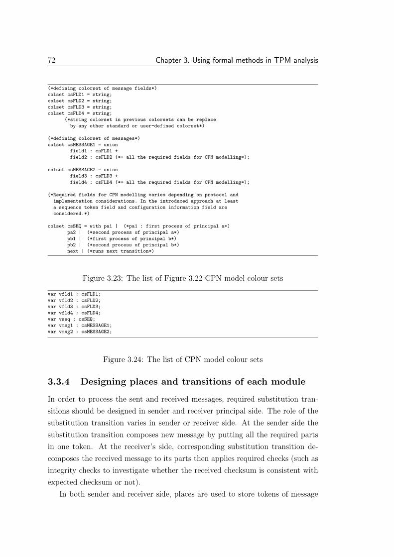
72 Chapter 3. Using formal methods in TPM analysis
(*defining colorset of message fields*)
colset csFLD1 = string;
colset csFLD2 = string;
colset csFLD3 = string;
colset csFLD4 = string;
(*string colorset in previous colorsets can be replace
by any other standard or user-defined colorset*)
(*defining colorset of messages*)
colset csMESSAGE1 = union
field1 : csFLD1 +
field2 : csFLD2 (*+ all the required fields for CPN modelling*);
colset csMESSAGE2 = union
field3 : csFLD3 +
field4 : csFLD4 (*+ all the required fields for CPN modelling*);
(*Required fields for CPN modelling varies depending on protocol and
implementation considerations. In the introduced approach at least
a sequence token field and configuration information field are
considered.*)
colset csSEQ = with pa1 | (*pa1 : first process of principal a*)
pa2 | (*second process of principal a*)
pb1 | (*first process of principal b*)
pb2 | (*second process of principal b*)
next | (*runs next transition*)
Figure 3.23: The list of Figure 3.22 CPN model colour sets
var vfld1 : csFLD1;
var vfld2 : csFLD2;
var vfld3 : csFLD3;
var vfld4 : csFLD4;
var vseq : csSEQ;
var vmsg1 : csMESSAGE1;
var vmsg2 : csMESSAGE2;
Figure 3.24: The list of CPN model colour sets
3.3.4 Designing places and transitions of each module
In order to process the sent and received messages, required substitution tran-
sitions should be designed in sender and receiver principal side. The role of the
substitution transition varies in sender or receiver side. At the sender side the
substitution transition composes new message by putting all the required parts
in one token. At the receiver’s side, corresponding substitution transition de-
composes the received message to its parts then applies required checks (such as
integrity checks to investigate whether the received checksum is consistent with
expected checksum or not).
In both sender and receiver side, places are used to store tokens of message

3.3. Proposal of a methodology to CPN model design 73
vseq
vseq
vmsg2 vmsg2 vmsg2 vmsg2
vmsg1vmsg1vmsg1vmsg1
Principal Asecond process
pa2
Principal Bsecond process
pb2
Principal Bfirst
processpb1
Commchannel 2
COMMCHL2a
Commchannel 1
COMMCHL1a
Principal Afirst
processpa1
start sendingmsg2
csSEQ
receivedmessage
twocsMESSAGE2
sentmessage
two
csMESSAGE2
csMESSAGE1
sentmessage
onecsMESSAGE1pa1 COMMCHL1a
COMMCHL2a
pb1
pb2pa2
receivedmessage
one
Figure 3.25: The sample protocol without intruder
fields. It is required to assign a suitable colour set to each place based on the
message field domain. Initial marking of place is used to assign default or initial
value to message fields. If the stored token in place is used globally in the model,
place is considered as a member of fusion set (illustrated in the Section 2.4).
Double arcs are usually used to connect fusion set members to the transition. In
hierarchical CPN models (illustrated in the Section 2.4), usually in each page a
number of places are input or output port. These places provide communication
between pages by connecting to corresponding sockets. The required input or
output tag and tool are available in tools such as CPN/Tools. Transitions are
used to combine different places to create the transfered message in each ex-
change. Guards are used to enable and disable transitions. The first transition
in each page uses a guard to check whether the received sequence token is con-
sistent with the current page or not. If they are not matched, the session will be
terminated. For all the connected arcs to the transition, whether they are input
or output, a suitable variable as inscription should be assigned. The modules of
Figure 3.25 model are shown in Figures 3.26 to 3.31.
In Figure 3.26 the details of pa1 module in Figure 3.25 is modelled. In this
figure, two tokens are fetched from ‘field 1 token’ and ‘field 2 token’
places and are stored in vfld1 and vfld2 variables. The ‘Compose message 1’
transition creates (vfld1, vfld2, vseq) output token using the stored tokens
in vfld1, vfld2 and vseq variables. The stored token in vseq variable is used
in order to apply sequence token mechanism. The produced output token will
be stored in ‘message one’ output port.
The stored token in the output port is passed to the ‘sent message one’
place in Figure 3.25. Then it is stored in ‘input message one’ place of Figure

74 Chapter 3. Using formal methods in TPM analysis
First process of principal A (pa1)
vseq
vfld2
(vfld1, vfld2, vseq)vfld1 Composemessage 1
messageone
OutcsMESSAGE1
sequencetoken
pb1
csSEQ
field 1token
csFLD1
field 2token
csFLD2
Out
1 1`pb1
Figure 3.26: The first process of principal A (pa1 page in Figure 3.25)
3.27. This token is simply passed to ‘output message one’ place by ‘Pass
message 1’ transitions. The token is stored in ‘received message one’ place
in Figure 3.25. Then, it is passed to the ‘Principal B first process’ module.
Passmessage 1
outputmessage
oneOut
csMESSAGE1
inputmessage
oneIn
csMESSAGE1In Out
Communication channel 1 (first format)
(vfld1, vfld2, vseq)(vfld1, vfld2, vseq)
Figure 3.27: The com. channel of exchange one (COMMCHL1a page)
The sent token through communication channel is received then processed by
the pb1 module. At first, the input token is stored in ‘message one’ input port
in Figure 3.28. Then, its fields are stored in ‘field 1 token’ and ‘field 2
token’ places. Sequence token mechanism is applied after checking the sequence
token colour by the [vseq=pb1] guard. Finally, the ‘start sending msg2’
transition changes the sequence token colour to 1`next in order to enable the
pb2 module (as seen in Figure 3.25) that creates the ‘principal B’ response.
The ‘Principal B second process’ (Figure 3.29) creates the B response to
the received message. Like pa1, this module fetches all the required tokens from
‘field 3 token’, ‘field 4 token’ and ‘next transition’ places. It then

3.3. Proposal of a methodology to CPN model design 75
1`next vseq
vfld1
vfld2
vseq
(vfld1, vfld2, vseq)
Process message 1
csSEQ
field 2token
csFLD2
field 1token
csFLD1
sequencetoken
csSEQ
messageone
IncsMESSAGE1
In
First process of principal B (pb1)
start sendingmsg2
start sendingmsg2OutOut
[vseq=pb1]
Figure 3.28: The first process of principal B (pb1 page)
stores them in vfld3, vfld4 and vseq variables. Finally, using the variables, the
‘Compose message 2’ transition creates (vfld3, vfld4, vseq) output token,
then stores it in ‘message two’ output port. The output token will be moved
to ‘sent message two’ place in Figure 3.25.
The ‘Comm channel 2’ module acts as a communication channel. Similar
to ‘Comm channel 1’, the stored token in ‘Sent message two’ is transfered to
‘input message two’ place in Figure 3.30. The ‘pass message 2’ moves the
input token to ‘output message two’ output port. The output port transfers
the token to ‘received message two’ place in Figure 3.25.
The ‘Principal A second process’ module in Figure 3.25 processes the
Principal B response. The ‘Process message 2’ transition, after receiving the
input token, applies the [vseq=pa2] guard in order to apply sequence token
mechanism and check whether pa2 page is enabled or disabled. When the page
is enabled, the (vfld3, vfld4, vseq) input token is decomposed. Then the
input token parts are stored in ‘field 3 token’ and ‘field 4 token’ places.
Finally, the sample protocol ends.
3.3.5 Validating model
The CPN model, before including the intruder, needs to be tested and validated.
Model testing is performed using the simulation tool embedded in the CPN/Tools

76 Chapter 3. Using formal methods in TPM analysis
Second process of principal B (pb2)
next
vseq
(vfld3, vfld4, vseq)
vfld4
vfld3Composemessage 2
current sequence
IncsSEQ
next transition
pa2
csSEQ
messagetwo
OutcsMESSAGE2
field 4token
csFLD4
field 3token
csFLD3Out
In
1 1`pa2
Figure 3.29: The second process of principal B (pb2 page)
(vfld3, vfld4, vseq) Passmessage 2
inputmessage
twoIn
csMESSAGE2
outputmessage
twoOut
csMESSAGE2Out In
(vfld3, vfld4, vseq)
Communication channel 2 (first format)
Figure 3.30: The com. channel of exchange two (COMMCHL2a page)
(discussed in the Section 2.4.1). The model should be traced to check whether
all the protocol steps are based on its specifications or not. If the protocol is
modelled exactly based on its specifications without any divergence, the protocol
should start from its initial state then, after following a limited number of steps,
ends at one of its final states. For protocols with different initial markings,
different independent tests are required. After validating the model operation,
the intruder will be included in the model.
3.3.6 Designing, validating and integrating intruder model
The Dolev-Yao is a popular powerful model where intruder is the medium that
carries the message. The intruder is able to forward, delete, edit, store and
create message. To implement the Dolev-Yao CPN model it is integrated with

3.3. Proposal of a methodology to CPN model design 77
vcfg
(vfld3, vfld4, vseq, vcfg)
vfld4
vfld3
Processmessage 2
[vseq=pa2]
currentconfig
COMMCHL
csCONFIG
messagetwo
IncsMESSAGE2
field 4token
csFLD4
field 3token
csFLD3In
Figure 3.31: The second process of principal A (pa2 page)
the communication channel. Sent messages through the channel are received by
the input socket of the intruder. Then, at the end of the intruder operation,
the output token is sent toward the receiver through the intruder output port.
Following operations and parts are required to model the intruder.
Intruder database
The intruder’s knowledge and initial values are stored in an incremental database.
Messages passed through the intruder, and all of the message components (fields)
are stored in the database. The intruder database colour set is a UNION
of colour sets of stored messages and their fields in the database. All of the
intruder CPN model pages need access to the intruder database. Implementing
the intruder database as a fusion set is a method to provide global accessibility
to it.
Intruder model design
In designing the intruder CPN model according to the Dolev-Yao approach, the
following functionalities are considered:
1. Intruder stores the received message in the intruder database.
2. Intruder decomposes input message to its parts then stores the received
message components in the intruder database.
3. Intruder fetches a previously stored message in its database then forwards
it toward the receiver.

78 Chapter 3. Using formal methods in TPM analysis
4. Intruder fetches separate fields of message from its database. Then the
intruder composes a new message using retrieved fields. Finally, intruder
sends the created message toward receiver.
Based on the modelled security property sometimes extra actions and op-
erations are required to be conducted by intruder. For example, to model the
authentication property the intruder needs to bypass the receiver. Modelling by-
pass operation needs creating new connections between intruders. Thus standard
intruder functionalities should be changed.
Intruder transitions guard
A guard for the first transition of each intruder page is required to prevent
concurrent runs of multiple instances of the intruder. This guard checks whether
the input sequence token for any intruder is equal to the predicted one or not.
If ‘yes’ the intruder will proceed with processing the input message, otherwise
the session will be terminated. It is possible to configure CPN models with more
complexity using more complicated guards for intruder transitions.
Intruder extra places (enabler places)
The intruder uses arcs to retrieve tokens from the database and to send pro-
duced messages to corresponding places. When the intruder creates a new faked
message after fetching the required data from the database, it returns them to
the intruder database for future use. Double arcs are used for fetching tokens
from the intruder database and returning them to it. When all the connected
arcs to the transition are double arcs, the input tokens always will be available
for the transition, thus the transition always will be enabled. To prevent un-
limited activation of transitions, special places with only one token should be
created and connected to the always enabled transitions. Putting one token in
the added place (named enabler place) enables the transition connected to the
enabler place only once. After consuming the token, the transition will never be
enabled again. An initial token is required for this type of places.
Intruder initial values and special requirements
The initial knowledge of the intruder is stored in database fields. The content
of the fields, which specifies the intruder knowledge, are defined and stored in

3.3. Proposal of a methodology to CPN model design 79
the database before starting the model simulation. Depending on the analysed
security property, the intruder structure varies. Intruders can cooperate with
each other in order to violate a specific property. It is even possible to create
connections between intruders and various parts of the CPN model in order to
perform new operations.
Intruder model test and integration
We recommend to model developers, after considering suitable initial marking,
check the separate parts of the intruder model in order to be more confident about
their operation, then simulate the integrated intruder CPN model. The tested
intruder CPN model (or models) can be integrated with the protocol model. It is
recommended to follow a hierarchical approach (top-down or bottom-up) in order
to facilitate and decrease the integration phase errors. Figure 3.32 demonstrates
the CPN model of sample protocol (Figure 3.21) integrated with intruder. The
new colour sets of model and revised substitution transitions are shown in Figures
3.33 to 3.42.
vmsg1vmsg1
vmsg2 vmsg2
vseq
vseq
vmsg2 vmsg2
vmsg1vmsg1
Intruder 2
int2
Intruder 1
int1
Principal Asecond process
pa2
Principal Bsecond process
pb2
Principal Bfirst
processpb1
Principal Afirst
processpa1
start sendingmsg2
csSEQ
receivedmessage
twocsMESSAGE2
sentmessage
two
csMESSAGE2
receivedmessage
onecsMESSAGE1
sentmessage
onecsMESSAGE1pa1 pb1
pb2pa2
int1
int2
Figure 3.32: The sample protocol with intruder
The colour sets and variables of the model integrated with the intruder, are
shown in Figure 3.33. In the figure, int1 and int2 are added to the csSEQ
colour set to extend sequence token mechanism and including intruder in it. The
new csINTDB colour set is defined in order to create intruder database. There
are two messages carried in sample protocol. Thus, two different fields named
fimsg1 and fimsg2 are defined to store these messages in intruder database.
Four different fields named, fifld1, fifld2, fifld3 and fifld4, are defined
in intruder database in order to store fimsg1 and fimsg2 parts in the database.
The operation of the pa1 (Figure 3.34), pa2 (Figure 3.35), pb1 (Figure 3.36)

80 Chapter 3. Using formal methods in TPM analysis
colset INT = int;
colset csFLD1 = string;
colset csFLD2 = string;
colset csFLD3 = string;
colset csFLD4 = string;
colset csSEQ = with pa1 |
pa2 | pb1 | pb2 |
int1 | int2 | next;
colset csMESSAGE1 = product
csFLD1 * csFLD2 * csSEQ;
colset csMESSAGE2 = product
csFLD3 * csFLD4 * csSEQ;
colset csINTDB = union
fifld1 : csFLD1 +
fifld2 : csFLD2 +
fifld3 : csFLD3 +
fifld4 : csFLD4 +
fimsg1 : csMESSAGE1 +
fimsg2 : csMESSAGE2;
var vfld1 : csFLD1;
var vfld2 : csFLD2;
var vfld3 : csFLD3;
var vfld4 : csFLD4;
var vseq : csSEQ;
var vmsg1 : csMESSAGE1;
var vmsg2 : csMESSAGE2;
Figure 3.33: The ample protocol with intruder colour sets and variables
and pb2 (Figure 3.37) pages in Figure 3.32 are similar to the corresponding pages
of pa1, pa2, pb1, pb2 substitution transitions in Figure 3.25. The only differ-
ence between these pages and corresponding pages, before adding the intruder, is
in the assigned values to the sequence token. For example, in the model without
the intruder sequence token, marking after leaving the pa1 page is changed to a
value that enables a suitable communication channel page. But, after adding the
intruder, the sequence token marking changes to a value that enables an intruder
CPN page.
The intruder model in Figure 3.38 applies all the intruder operations on sent
message from principal A to B through first protocol exchange. Intruder at
first stores the received message in ‘message one’ input port and its parts in
intruder database by enabling ‘Store message one and its fields in DB’
transition. The 1`fifld1(vfld1)++1`fifld2(vfld2)++1`fimsg1(vmsg1) in-
scription stores vfld1, vfld2 and vmsg1 in the fifld1, fifld2 and fimsg1
database fields respectively. Then, ‘fetch and forward message’ or ‘create
and send new message’ or ‘user-defined actions’ is enabled. Intruder in
the first substitution transition fetches one message from its database. In the
second substitution transition, the intruder creates a new message by fetching

3.3. Proposal of a methodology to CPN model design 81
First process of principal A (pa1)
vseq
vfld2
(vfld1, vfld2, vseq)vfld1 Composemessage 1
messageone
OutcsMESSAGE1
sequencetoken
pb1
csSEQ
field 1token
csFLD1
field 2token
csFLD2
Out
1 1`pb1
Figure 3.34: The first process of principal A in the sample protocol with theintruder (pa1 page)
required fields from intruder database. The last substitution transition, which
its detail is not defined in this research, implements the required operations for
interaction between intruders or user-defined actions. The result token of all sub-
stitution transitions is stored in ‘new message one’ place. Then the required
checks are applied and the produced token will be sent to the recipient principal
through the ‘output message one’ output port.
The intruder first sub-module, i1frd, is shown in Figure 3.39. The ‘Fetch
and forward message 1’ transition fetches a token with the same colour set as
the first sent message from the intruder database, stores it in vmsg1 variable,
then sends it to the ‘new message one’ output socket.
The intruder second sub-module, i1crt, detail is shown in Figure 3.40. The
required tokens to produce a message, field1 and field2, are fetched from
fifld1 and fifld2 database fields then, after storing them in vfld1 and vfld2
variables, they are used to create new (vfld1, vfld2, next) token. The cre-
ated token is stored in the ‘new message one’ output port.
The last intruder substitution transition is defined based on the analysed
property, interactions and cooperations between intruders. There is no specific
model defined for that in this methodology. The operation of the second intruder
(Figure 3.41) and its sub-modules (i2frd and i2crt) are the same as first in-
truder and its sub-modules. Therefore, they are not illustrated and only their
models are shown in Figures 3.41, 3.42, and 3.43.

82 Chapter 3. Using formal methods in TPM analysis
Second process of principal A (pa2)
(vfld3, vfld4, vseq)
vfld4
vfld3
Processmessage 2
[vseq=pa2]
messagetwo
IncsMESSAGE2
field 4token
csFLD4
field 3token
csFLD3In
Figure 3.35: The second process of principal A in the sample protocol with theintruder (pa2 page)
3.3.7 Verifying model using ASK-CTL
After creating protocol CPN model, including required parts in order to verify
security property and validating the model, security property should be verified.
In our proposed methodology ASK-CTL is applied on created protocol state
space to verify the property. The ASK-CTL ability to verify multiple protocol
marking at the same time, makes it a flexible method for protocol verification.
3.3.8 Adding configurability to the model (if required)
Configurable models include or exclude some parts in or from the model. They
increase traceability, simplicity and readability of the model in different config-
urations. In the sample protocol CPN model it is possible to include or exclude
the intruder in or from the CPN model by considering different configurations.
Intruder exclusion simplifies model simulation to investigate whether the CPN
model works properly or not. Including the intruder in a previously tested model
makes testing the new model more robust and easier.
Model configurations are selected by assigning different values to the defined
constants (values in the CPN model) in the declaration part of the model. At
the beginning of compiling the CPN model using the CPN/Tools according to
the assigned value to the configuration constant, the corresponding configuration
will be selected. For example in our models, when {vcfg=INTRUDER}, intruder
is included in the model. Assigning COMMCHL using {vcfg=COMMCHL} inscription

3.3. Proposal of a methodology to CPN model design 83
First process of principal B (pb1)
1`next
vseq
vfld1
vfld2
vseq
(vfld1, vfld2, vseq)
start sendingmsg2
Process message 1
[vseq=pb1]
start sendingmsg2Out
csSEQ
field 2token
csFLD2
field 1token
csFLD1
sequencetoken
csSEQ
messageone
IncsMESSAGE1
In
Out
Figure 3.36: The first process of principal B in the sample protocol with theintruder (pb1 page)
to vcfg exclude the intruder from CPN model. The colour sets and values of
Figure 3.44 can be defined then added to the Figure 3.33 colour sets in order to
produce different configurations for Figure 3.32 model. The final model colour
sets and variables are shown in Figure 3.47.
When a configurable model is designed, to prevent running excluded parts of
the model, suitable guards or inscriptions should be added to all or a number
of transitions and guards. For example, in ‘Intruder 1’ and ‘Intruder 2’
models, for the first transition (the first enabled transition when a CPN page is
activated) a guard like Figure 3.45 is required.
The sequence of enabling protocol CPN pages is controlled by sequence token
mechanism. In configurable models the token value changes based on model
current configuration. In the sample model, table 3.1 shows the value of sequence
token at the end of different substitution transitions. For example, at the end of
pa1 page when intruder is included in the model, int1 value is assigned to the

84 Chapter 3. Using formal methods in TPM analysis
Second process of principal B (pb2)
nextvseq
(vfld3, vfld4, vseq)
vfld4
vfld3Composemessage 2
current sequence
IncsSEQ
next transition
pa2
csSEQ
messagetwo
OutcsMESSAGE2
field 4token
csFLD4
field 3token
csFLD3Out
In
1 1`pa2
Figure 3.37: The second process of principal B in the sample protocol with theintruder (pb2 page)
Next substitution transitionCurrent substit. trans. vcfg=INTRUDER vcfg=COMMCHLPrincipal A (pa1) Int1 pb1Principal B (pb1) pb2 pb2Principal B (pb2) Int2 pa2Intruder1 pb1 unknownIntruder2 pa2 unknown
Table 3.1: The sequence token value at the end of each substitution transition
sequence token in order to enable first intruder page.
Table 3.1 is created by assuming no communication between ‘Intruder 1’
and ‘Intruder 2’. Assuming this cooperation ‘Intruder 1’ is able to assign
different values to the sequence token to move it either toward ‘principal B’
first process or ‘Intruder 2’. To send the sequence token to ‘Intruder 2’,
new paths between intruders must be created. The applied changes to the sample
protocol to make it a configurable model are shown in Figures 3.46 to 3.55.
In Figure 3.46 required sub-models for all the communication channels and
intruder models are included. In Figure 3.47 required colour sets, values and
variables for configurable model are shown. The sent and received message colour
sets in this Figure are changed in order to include configuration field in them.

3.3. Proposal of a methodology to CPN model design 85
vmsg1
vmsg1
vmsg1
vmsg1
vmsg1
vseq
vseq
vseq
next
(vfld1, vfld2, vseq)vmsg1
1`fifld1(vfld1)++1`fifld2(vfld2)++1`fimsg1(vmsg1)
(vfld1, vfld2, vseq)
(vfld1, vfld2, vseq)
Do necessary checks
user-defined actions
i1ud
create and send new message
i1crt
fetch andforward message
i1frd
Store messageone and its fields in DB
Process message 1
[vseq=int1]
outputmessage
oneOutcsMESSAGE1
new message
onecsMESSAGE1
createand send new
messagecsSEQ
intruderDB
INTDBcsINTDB
tmp message
onecsMESSAGE1
messageone
IncsMESSAGE1
In
INTDB
Out
i1frd
i1crt
i1ud
Figure 3.38: The intruder process of exchange one in the sample protocol (int1page )
The first process of principal A model is shown in Figure 3.48. Its operation
and components are mostly similar to the Figure 3.26 and Figure 3.34. The only
difference is adding a place ‘current config’ to the model to keep track of
model configuration. The model configuration token is fetched from ‘current
config’ then is stored in vcfg variable to be transfered through the model.
The pa2 (Figure 3.49) and pb1 (Figure 3.50) models are similar to their corre-
sponding models before (Figures 3.31 and 3.28) or after (Figures 3.35 and 3.36)
including intruder. The only difference is in input message token that includes
a configuration token.
The second page of principal B, pb2, in Figure 3.51 produces the received
message response that, in configurable model, is sent either to the communication
channel or the intruder. Therefore, its functionality in the configurable model
will be different in non-configurable models. This model, in addition to required
fields of the response message, fetches the current model configuration token from
‘current config’ place and then stores it in the message response then sends

86 Chapter 3. Using formal methods in TPM analysis
vmsg1
fimsg1(vmsg1)
vseq Fetch and forwardmessage 1
intruderDB
INTDBcsINTDB
new message
oneOut
csMESSAGE1
createand send new
messageIn
csSEQIn Out
INTDB
Figure 3.39: Forwarding the stored message sub-process in the intruder one(i1frd page)
1`fifld1(vfld1)++1`fifld2(vfld2)
(vfld1, vfld2, next)vseq Fetch fields
and send new message 1
intruderDB
INTDBcsINTDB
new message
oneOut
csMESSAGE1
createand send new
messageIn
csSEQIn Out
INTDB
Figure 3.40: Creating the new message sub-process in ‘intruder 1’ (i1crtpage)
the message toward either the communication channel or the intruder.
In Figure 3.52, when model configuration has excluded intruder and [vcfg=COMMCHL]
guard is evaluated to true, ‘Pass message 1’ transition will be enabled and
received message token is passed to the next principal. The second exchange
communication channel model in Figure 3.53 is similar to first communication
channel.
The intruder models functionality, in Figures 3.54 and 3.55 are similar to
intruder operations in non-configurable models. They are only different in the
[vseq=int1 andalso vcfg=INTRUDER] guard of first transition that, when in
current configuration no intruder is included (vcfg=COMMCHL is true), prevents
intruder pages to be enabled.

3.3. Proposal of a methodology to CPN model design 87
vmsg2
vmsg2
vmsg2
vmsg2
vmsg2
vseq
vseq
vseq
next
(vfld3, vfld4, vseq) vmsg2
1`fifld1(vfld3)++1`fifld2(vfld4)++1`fimsg2(vmsg2)
(vfld3, vfld4, vseq)
(vfld3, vfld4, vseq)
Do necessary checks
user-defined actions
i2ud
create and send new message
i2crt
fetch andforward message
i2frd
Store messageone and its fields in DB
Process message 2
[vseq=int1]
outputmessage
oneOutcsMESSAGE2
new message
twocsMESSAGE2
createand send new
messagecsSEQ
intruderDB
INTDBcsINTDB
tmp message
twocsMESSAGE2
messagetwo
IncsMESSAGE2
In
INTDB
Out
i2frd
i2crt
i2ud
Figure 3.41: The intruder process of exchange two in the sample protocol (int2page)
vmsg2
fimsg2(vmsg2)
vseq Fetch and forwardmessage 2
intruderDB
INTDBcsINTDB
new message
oneOut
csMESSAGE2
createand send new
messageIn
csSEQIn Out
INTDB
Figure 3.42: Forwarding the stored message sub-process in intruder two (i2frdpage)
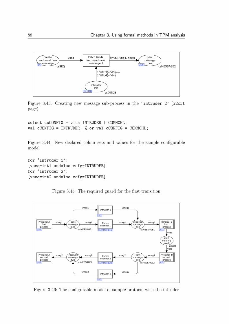
88 Chapter 3. Using formal methods in TPM analysis
1`fifld3(vfld3)++1`fifld4(vfld4)
(vfld3, vfld4, next)vseq Fetch fields and send new
message 1
intruderDB
INTDBcsINTDB
new message
oneOut
csMESSAGE2
createand send new
messageIn
csSEQIn Out
INTDB
Figure 3.43: Creating new message sub-process in the ‘intruder 2’ (i2crtpage)
colset csCONFIG = with INTRUDER | COMMCHL;
val cCONFIG = INTRUDER; % or val cCONFIG = COMMCHL;
Figure 3.44: New declared colour sets and values for the sample configurablemodel
for ‘Intruder 1’:
[vseq=int1 andalso vcfg=INTRUDER]
for ‘Intruder 2’:
[vseq=int2 andalso vcfg=INTRUDER]
Figure 3.45: The required guard for the first transition
vmsg1vmsg1
vmsg2 vmsg2
vseq
vseq
vmsg2 vmsg2 vmsg2 vmsg2
vmsg1vmsg1vmsg1vmsg1
Intruder 2
int2
Intruder 1
int1
Principal Asecond process
pa2
Principal Bsecond process
pb2
Principal Bfirst
processpb1
Commchannel 2
COMMCHL2a
Commchannel 1
COMMCHL1a
Principal Afirst
processpa1
start sendingmsg2
csSEQ
receivedmessage
twocsMESSAGE2
sentmessage
two
csMESSAGE2
receivedmessage
one
sentmessage
onecsMESSAGE1pa1 COMMCHL1a
COMMCHL2a
pb1
pb2pa2
int1
int2
csMESSAGE1
Figure 3.46: The configurable model of sample protocol with the intruder

3.3. Proposal of a methodology to CPN model design 89
colset INT = int;
colset csFLD1 = string;
colset csFLD2 = string;
colset csFLD3 = string;
colset csFLD4 = string;
colset csSEQ = with pa1 |
pa2 | pb1 | pb2 | int1 |
int2 | next;
colset csCONFIG = with
INTRUDER | COMMCHL;
colset csMESSAGE1 = product
csFLD1 * csFLD2 * csSEQ * csCONFIG;
colset csMESSAGE2 = product
csFLD3 * csFLD4 * csSEQ * csCONFIG;
var vfld1 : csFLD1;
colset csINTDB = union
fifld1 : csFLD1 +
fifld2 : csFLD2 +
fifld3 : csFLD3 +
fifld4 : csFLD4 +
fimsg1 : csMESSAGE1 +
fimsg2 : csMESSAGE2;
var vfld2 : csFLD2;
var vfld3 : csFLD3;
var vfld4 : csFLD4;
var vseq : csSEQ;
var vcfg : csCONFIG;
var vmsg1 : csMESSAGE1;
var vmsg2 : csMESSAGE2;
val cCONFIG = COMMCHL;
Figure 3.47: The colour sets of configurable model
First process of principal A (pa1)
vseq
vcfgvfld2
(vfld1, vfld2, vseq, vcfg)vfld1 Composemessage 1
messageone
OutcsMESSAGE1
sequencetoken
pb1
csSEQ
field 1token
csFLD1
field 2token
csFLD2
currentconfig
GF_cfg
COMMCHL
csCONFIG
Out
GF_cfg
Figure 3.48: The first process of principal A in the configurable model (pa1 page)

90 Chapter 3. Using formal methods in TPM analysis
Second process of principal A (pa2)
(vfld3, vfld4, vseq, vcfg)
vfld4
vfld3
Processmessage 2
[vseq=pa2]
messagetwo
IncsMESSAGE2
field 4token
csFLD4
field 3token
csFLD3In
Figure 3.49: The second process of principal A in the configurable model (pa2page)
1`next vseq
vfld1
vfld2
vseq
(vfld1, vfld2, vseq, vcfg)
Process message 1
[vseq=pb1]
csSEQ
field 2token
csFLD2
field 1token
csFLD1
sequencetoken
csSEQ
messageone
IncsMESSAGE1
In
start sendingmsg2
start sendingmsg2OutOut
First process of principal B (pb1)
Figure 3.50: The first process of principal B in the configurable model (pb1 page)

3.3. Proposal of a methodology to CPN model design 91
Second process of principal B (pb2)
next
vcfg
vseq
(vfld3, vfld4, vseq, vcfg)
vfld4
vfld3Composemessage 2
current sequence
IncsSEQ
currentconfig
GF_cfg
COMMCHL
csCONFIG
next transition
pa2
csSEQ
messagetwo
OutcsMESSAGE2
field 4token
csFLD4
field 3token
csFLD3Out
In
GF_cfg
Figure 3.51: The second process of principal B in the configurable model (pb2page)
(vfld1, vfld2, vseq, vcfg) (vfld1, vfld2, vseq, vcfg)Passmessage 1
[vcfg=COMMCHL]
outputmessage
oneOut
csMESSAGE1
inputmessage
oneIn
csMESSAGE1In Out
Communication channel 1 (first format)
Figure 3.52: The com. channel of first exchange in the configurable model
(vfld3, vfld4, vseq, vcfg)Pass
message 2
inputmessage
twoIn
csMESSAGE2
outputmessage
twoOut
csMESSAGE2Out In
[vcfg=COMMCHL](vfld3, vfld4, vseq, vcfg)
Communication channel 2 (first format)
Figure 3.53: The com. channel of second exchange in the configurable model

92 Chapter 3. Using formal methods in TPM analysis
vmsg1
vmsg1
vseq
next
(vfld1, vfld2, vseq, vcfg)vmsg1
1`fifld1(vfld1)++1`fifld2(vfld2)++1`fimsg1(vmsg1)
(vfld1, vfld2, vseq, vcfg)
(vfld1, vfld2, vseq, vcfg)
property-basedprocess
i1chgp
create and send new message
i1crt
fetch andforward message
i1frd
Store messageone and its fields in DB
Process message 1
csMESSAGE1
new message
onecsMESSAGE1
createand send new
message
intruderDB
INTDBcsINTDB
tmp message
onecsMESSAGE1
messageone
IncsMESSAGE1
In
INTDB
i1frd
i1crt
i1chgp
vmsg1
vseq
vseq vmsg1
vmsg1
[vseq=int1 andalsovcfg=INTRUDER]
Do necessary checks
outputmessage
oneOutOut
csSEQ
Figure 3.54: The first intruder of the configurable model
vmsg2
vmsg2
vmsg2
vseq
next
(vfld3, vfld4, vseq, vcfg) vmsg2
1`fifld1(vfld3)++1`fifld2(vfld4)++1`fimsg2(vmsg2)
(vfld3, vfld4, vseq, vcfg)
(vfld3, vfld4, vseq, vcfg)
Do necessary checks
property-basedprocess
i2chgp
create and send new message
i2crt
fetch andforward message
i2frd
Store messageone and its fields in DB
Process message 2
outputmessage
oneOutcsMESSAGE2
new message
twocsMESSAGE2
createand send new
message
intruderDB
INTDBcsINTDB
tmp message
twocsMESSAGE2
messagetwo
IncsMESSAGE2
In
INTDB
Out
i2frd
i2crt
i2chgp
vmsg2
[vseq=int1 andalsovcfg=INTRUDER]
vmsg2
vseq
vseqcsSEQ
Figure 3.55: The second intruder of the configurable model

3.4. Recommendations to create CPN model 93
3.4 Recommendations to create CPN model
Created CPN models based on previous methodology need minor corrections,
optimisation and improvement. Based on experiences from modelling NSPK
and two protocols in Chapter 4, a number of recommendations are provided in
the following list. While a number of them (such as recommendation 2) can be
easily applied during modelling, application of others (like recommendation 3) is
more complicated and requires creating sub-models.
1. For transitions where all input arcs are double arc, an enabler place should
be considered. A limited number of tokens (based on the number of times
transition will be enabled) are stored in the enabler place as the place initial
value.
2. All the tokens read from a member of a global fusion set should be returned
to these places using double arcs. If tokens are not returned, members of
fusion sets in other pages do not provide required tokens to connected
transitions. Thus, they never will be enabled.
3. Concurrent access to one intruder database field causes deadlock. Deadlock
prevention for the fields with multiple concurrent access can be managed
by serialising access to the field.
4. In order to prevent state space explosion as much as possible, the size of
the intruder database should be kept as small as possible by:
(a) Avoiding storage of duplicate tokens in the database.
(b) If it is possible to compute any token based on the value of other
stored tokens, storing it in the database is not recommended.
(c) If a specific token is used in protocol late stages its early computation
and storage in intruder database is not recommended. It is better to
compute then store it in the database as late as possible.
5. Hierarchical design and implementation of CPN models is highly recom-
mended to reduce modelling complexity. It increases model readability on
the screen and prevents unnecessary scrolls. Both top-down or bottom-up
approaches can be used.

94 Chapter 3. Using formal methods in TPM analysis
6. Each CPN model needs an initiator to start running protocol. To specify
the initiator, required tokens are stored as initial marking in places that
will be enabled at the start of modelling, before all the other places.
7. The illustrated approach to model the intruder does not assume any com-
munication between intruders. Designing the CPN model of cooperat-
ing intruders needs more operations (substitution transitions in intruder
model that through them intruders communicate with each other) and in-
put/output ports to be implemented. Figure 3.56 shows the Figure 3.25
sample protocol while intruders have communication ability. The detailed
models of ‘Intruder 1’ and ‘Intruder 2’ modules in Figure 3.56 are
not designed at current state of this research.
vmsg1vmsg1
vmsg2 vmsg2
vseq
vseq
vmsg2 vmsg2
vmsg1vmsg1
Principal Asecond process
pa2
Principal Bsecond process
pb2
Principal Bfirst
processpb1
Principal Afirst
processpa1
start sendingmsg2
csSEQ
receivedmessage
twocsMESSAGE2
sentmessage
two
csMESSAGE2
receivedmessage
onecsMESSAGE1
sentmessage
onecsMESSAGE1pa1 pb1
pb2pa2
Intruder 1
int1int1
csSEQ
end cooperations
csSEQ
start cooperation
Intruder 2
int2int2
vseq vseqRequired cooperations
coopcoop
Figure 3.56: The sample protocol with intruder while intruders have cooperations
3.5 Discussion of general modelling methodol-
ogy
The general modelling methodology proposes a framework to generate security
protocol CPN model. Successful application of the proposed steps in Chapters 4
and 5 demonstrates the methodology helps produce models in less time. Created
models can be used to develop a library of CPN objects and toolboxes (palettes
in CPN/Tools) to generate CPN models. At the end of the modelling, usage of
logics such as computational tree logic in order to model verification makes the
approach more powerful.

3.6. Summary 95
The proposed steps and processes generally talk about an intruder based
on the Dolev-Yao model. The usage of other intruder models may change the
methodology. Moreover, the designed approach is proposed after analysing the
authentication property of protocols. Therefore, analysis of other security prop-
erties may change the methodology and its steps.
The proposed methodology has been designed after producing a number of
CPN models. As future work it is better to analyse a variety of different proto-
cols, such as key management, key agreement or authentication protocols with
different goals, in order to revise the methodology based on successful experi-
ences and experiments. After analysing each protocol, the modelling experiences
and feedbacks can be applied on the methodology in order to decrease errors,
optimise steps and make it more efficient.
3.6 Summary
This chapter illustrated CPN usage in protocol modelling. It replicated the
Needham-Schroder public key (NSPK) protocol CPN model of Al-Azzoni in
CPN/Tools (in spite of its ancestor Design/CPN). The successful implemen-
tation of the Design/CPN NSPK Al-Azzoni model in CPN/Tools demonstrates
the applicability of CPN/Tools to produce CPN models for security protocols.
The modelling outcome and experiences, in addition to the experiences from
Chapters 4 and 5, are used in order to propose a general modelling methodology
using CPN. The methodology makes Al-Azzoni approach more structured by
proposing specific steps. The included verification step adds the advantages and
capabilities of ASK-CTL to the methodology and makes it more powerful in
comparison with Al-Azzoni method. The next chapter will introduce how OSAP
and SKAP protocols can be modelled and analysed using CPN and CPN/Tools.

96 Chapter 3. Using formal methods in TPM analysis

Chapter 4
Analysis of two TPM protocols
TCG enforces sent commands to the TPM that affect or reveal TPM secrets
to be authorised. Authorisation protocols are used to authenticate users and
processes before access to the TPM internal secrets be granted to them. Their
importance has made them good candidate for analysis and applying proposed
CPN modelling approach.
The Object-Specific Authorisation Protocol (OSAP) establishes a session to
prove knowledge of authorisation data for one TPM object. Multiple commands
can be authorised without establishing additional sessions, in order to obtain
access to a specific object. This command minimizes the exposure of long-term
authorisation values [94]. The shared authData problem is found in OSAP by
Chen and Ryan [36]. They have solved this issue in new SKAP protocol by
encrypting the authData [36].
In this chapter two hierarchical CPN models are created for both an OSAP
and SKAP authorisation protocols in the CPN/Tools by applying the method-
ology described in the previous chapter. A state space is generated from the
created model. This is then used to analyse the authentication property. In
particular, a number of states representing the violation situations of the au-
thentication property are defined. Then, using state space analysis and CTL,
the violation conditions of the authentication property are determined and veri-
fied. This chapter outline is:
1. Illustrating used methods and approaches in modelling.
97
98 Chapter 4. Analysis of two TPM protocols
2. Modelling OSAP protocol, its intruder, verification of the OSAP authenti-
cation property and discussion in the Section 4.2.
3. Modelling SKAP protocol, its intruder, verification of the SKAP authenti-
cation property and discussion in the Section 4.3.
4. Chapter conclusion.
4.1 Applied approaches to model OSAP and
SKAP
In this chapter the OSAP and SKAP CPN models are created by applying Chap-
ter 3 proposed methodology. Then in order to analyse authentication property,
in both protocols the property and required Dolev-Yao intruder CPN models
are designed and integrated with protocol model. As the result of integrating
intruder and authentication property models with protocol models and applying
the Section 4.1 approaches new models have the following features:
1. The risk of state space explosion is low.
2. The model errors can be found faster.
3. In order to facilitate model validation multiple configurations are combined
in one model.
4. It is possible to identify whether authentication property can be violated
by intruder or not.
These approaches are illustrated in the next sections.
4.1.1 Modelling and verification of authentication prop-
erty
Authentication protocols can be modelled [124, 59], analysed [21, 105] or verified
[56, 89, 107, 125] in different ways. When the authentication property is violated
intruder can manipulate user and TPM interactions. The intruder is able to
start and finish a session with either user or TPM without involving the other
agent. To verify this criterion a specific CPN model for the intruder should be

4.1. Applied approaches to model OSAP and SKAP 99
designed that provides necessary interactions between intruders to bypass TPM.
The intruder model details are illustrated in the Section 4.1.2.
A simple way to demonstrate the violation of the authentication property is
demonstrating the ability of an intruder to complete the OSAP or SKAP pro-
tocol successfully (that is, with the user accepting the new session authorisation
data at the end of the protocol without even involving the TPM whatsoever in
the process). In other words, in our model, the authentication property of the
OSAP or SKAP protocol is violated if the intruder intercepts the message dur-
ing first and third message exchanges and does not forward the message to the
TPM; instead, the Intruder 2 and Intruder 4 modules are executed following
the interception of the messages (from the user) during first and third message
exchange respectively.
A suitable ASK-CTL formula is required to verify not only if a session has
ended successfully but also if TPM is involved in the protocol exchanges or not.
Our proposed ASK-CTL formulas for verification of OSAP and SKAP models
are illustrated in Section 4.2.4 and Section 4.3.4.
In this chapter the CPN/Tools state space is used in order to evaluate the
authentication property of both OSAP and SKAP protocols for the first time.
To evaluate the authentication property, after creating and validating the proto-
col CPN model, to verify the authentication property, several formal notations,
predicates, and operator are defined at first. Then, a condition (in an ASK-
CTL statement) that its fulfillment will violate the authentication property of
the OSAP (SKAP) protocol is formalised. Finally, the ASK-CTL statement is
executed to verify if the authentication property can be violated.
4.1.2 Intruder model and database
The intruder model can be designed differently based on intruder capabilities,
interactions with other intruders and entities, the modelled protocol and property
of interest. Our intruder model is based on the Dolev-Yao [126] approach to verify
the authentication property. The Dolev-Yao model (as illustrated in the Section
2.2.1) assumes the intruder as the medium that transfers messages and is able to
edit, remove, forward, duplicate and create new messages. In other words, the
intruder acts as a man in the middle who can modify sent and received messages
between the TPM and the user or can bypass the TPM altogether. Intruder
interaction with other entities follows either the model of Figure 4.1 or Figure

100 Chapter 4. Analysis of two TPM protocols
4.2.
genuine
message
faked
message
Intruder Receiver Sender
Figure 4.1: The sent message is changed by the intruder
genuine
message
faked
message
Intruder 1 Receiver Sender
Intruder 2 Receiver Sender
Figure 4.2: The intruder has bypassed receiver
At the start of the protocol the intruder has some initial public knowledge,
like any other principal involved in the protocol. This knowledge increases by
intercepting sent or received messages. Therefore, a suitable data structure for
storage, such as the proposed one by Al-Azzoni [12], is required. In this re-
search, the intruder database is implemented using a user-defined colour set,
named csINTDB. This colour set is union of different fields that intruder stores
intercepted tokens in them. Intruder uses the stored tokens in order to create
faked messages in different protocol stages.
4.1.3 Sequence token mechanism
CPN models with large state space usually suffer from the state space explosion
problem. State space explosion occurs when the number of state space occurrence
graph nodes increases significantly such that the state space cannot be computed.
State space explosion can be prevented by optimising the designed model or using
tools that apply more optimised state space generation algorithms such as that
introduced by Westergaard [123]. This research focuses on optimising the model.
Al-Azzoni proposes a token passing mechanism to prevent concurrent runs of the
protocol sessions and message exchanges [11]. In the protocol model a token with
constant colour moves between transitions and pages. Only pages and transitions
that the sequence token reaches can be run and activated. Thus, the concurrent
run of multiple pages will be impossible.
The proposed sequence token mechanism improves the Al-Azzoni approach
and makes it more readable specially in complex models by proposing a special

4.1. Applied approaches to model OSAP and SKAP 101
colour set (in this research it is named csSEQ). This colour set defines one
member for each CPN page. These values are allocated to a token (named
sequence token) which circulates between pages based on protocol sequences.
The guard of the first transition of each page compares the sequence token value
with a unique predefined value for the page (that is a member of csSEQ colour
set). When the compared values are equal the page will be enabled; otherwise,
the sequence token is passed to the next page. Inside any page of the model
the assigned value of the sequence token is ‘next’. At the end of the page the
unique value of next page is retrieved from the csSEQ colour set and is allocated
to the sequence token. Using this approach the previous and next page of any
CPN page model can be distinguished easily and readability of model increases.
Applying the sequence token mechanism prevents the parallel run of protocol
sessions. To analyse parallel concurrent sessions this approach can be extended
by adding a suitable page identifier for concurrent pages and designing a suitable
mechanism to determine next possible active page at the end of each page.
4.1.4 Parameterisation
Parameterisation is a technique used by researchers to change included compo-
nents in the model to create different sub-models. In this approach the model
operation changes by setting different constants to different predefined values.
This research uses parameterisation to divide state space and to create config-
urable models.
Using parameterisation to divide state space
To prevent state space explosion, state space can be divided into a number of
sub-sets. The state space division is achieved by dividing the CPN model in
sub-models using parameterisation.
Parameterisation is a method to define a number of setting values (constants)
in the declaration part of the CPN model. Assigning different values (constants)
to the settings during the compile time of the model generates different CPN
sub-models. Usage of a specific set of values for the parameters enables one
sub-set of the model behaviour to be generated during simulation. Thus, after
computing the state space a smaller SCC graph is generated. It is clear that for
a smaller CPN sub-model the possibility of state space explosion is less than the
union of the sub-model with another CPN sub-model.

102 Chapter 4. Analysis of two TPM protocols
To investigate specific criteria, specially while finding a violation condition,
the smaller CPN model with smaller SCC graph is searched first. Any violation
condition available in smaller SCC graph will be available in its union with an-
other SCC graph. If the violation condition could not be found in the smaller
graph then its union with other sub-graphs will be searched for violation condi-
tion. This approach works only when violation condition can be found in one of
the sub-graphs or the union of all sub-graphs is not faced with state space explo-
sion. To apply this method properly, finding suitable sub-graphs and designing
required parameters in the model are important.
Creating a configurable model
CPN models need to be tested to discover possible bugs. The unvalidated mod-
els possibly contain infinite loops that cause state space explosion. To facilitate
model validation it is better to divide the model into different independent mod-
ules and test each module separately. In CPN/Tools there is no special tool in
order to divide model to sub-models and validate sub-models separately. So it
is recommended to design a configurable model that only specific parts of the
model are activated by setting different constants. After testing each module it
can be included in the model again by resetting the configuration defined values.
4.1.5 Error-discovery mechanism
The error-discovery approach is proposed as a new technique in this research
to facilitate the discovery of errors (unpredicted markings that stop the model
simulation or state space creation, but the modelling is not in the end marking)
that occur during the model simulation. The mechanism stores information
regarding errors that have occurred in specific places using special tokens with
suitable values. The stored token value precisely describes the error. The model
developer can easily reproduce the error marking and trace the model before
and after the error marking. To implement the error-discovery mechanism after
identifying model errors a colour set with a specific value for each error was
specified.
To implement the mechanism, a suitable colour from error-discovery colour
set is assigned to a token. Then the token is stored in a global fusion set (with
the same colour set as the error token). At the end of the protocol or other

4.2. Modelling OSAP 103
stages, by checking the available tokens in error global fusion set the last error
can be easily found.
1`termses
verr
1`incorrect_hmac1
vhmac1
vhmac2 vhmac2
vhmac1
terminatemodel
Extract HMAC from input
exrt HMAC
compute HMAC
cmp HMAC
compare HMACs
csSEQ
Global Error
errorcsERROR
tmp ERROR
csERROR
extractedHMAC
csHMAC
computed HMAC
csHMAC
error
cmp HMAC
exrt HMAC
end session
[not (vhmac1=vhmac2)]
verr
Figure 4.3: The error-discovery mechanism
For example, in Figure 4.3 when an integrity HMAC is received, it is ex-
tracted by ‘Extract HMAC from input’ substitution transition and stored in
‘extracted HMAC’ place. Based on stored values by receiver entity another
HMAC is computed and will be stored in the ‘computed HMAC’ place. The
received HMAC and computed HMAC are compared by the ‘compare HMACs’
transition. When they are not equal an error has happened so a specific token
and incorrect hmac1 predefined value will be stored in the ‘tmp ERROR’ place.
The ‘terminate model’ transition by storing 1`termses token in the ‘end
session’ place indicates session termination. Storage of 1`incorrect hmac1 er-
ror token in the ‘Global Error’ place (as a member of global fusion set error)
will help to find where and why the error has happened.
4.2 Modelling OSAP
OSAP is a challenge response protocol used to authorise users of protected TPM
objects by demonstrating their knowledge of the authorisation data. A shared
secret key (denoted as S) is generated at the end of a successful OSAP session.
A sample usage of this protocol is illustrated by Chen and Ryan [35] whereby
the OSAP protocol was executed first before the user called the TPM to create a
key as the child of a parent key. Figure 4.4 (slightly modified from [35]) illustrates
the protocol sequence. The next sub-section illustrates the protocol.
4.2.1 OSAP protocol description
To facilitate easy referencing of the messages being interchanged in this protocol,
each message being sent and received (shown in Figure 4.4 is labeled: the label of
the first message being sent from the user to the TPM is OSAP Msg#1, followed

104 Chapter 4. Analysis of two TPM protocols
by OSAP Msg#2 (from the TPM back to the user), and so on (OSAP Msg#3
and OSAP Msg#4 ). To ensure a more coherent link between the protocol and
our formal CPN model, Figure 4.4 also explicitly captures the internal processing
conducted by both the user and TPM (represented by the ‘Process TPM OSAP’,
‘Process TPM CreateWrapKey message’, ‘Process TPM OSAP response’, and
‘Process TPM CreateWrapKey(...) Response’ boxes .
TPM
� = hmac���� �����
, �����
OSAP_Msg#2 : �ℎ, �� , �����
OSAP_Msg#4 : keyblob,��( , hmac)��
( , ��
Process TPM_CreateWrapKey message
Process TPM_OSAP
USER
� = hmac���� �����
, �����
OSAP_Msg#1 :TPM_OSAP,-ℎ, �����
OSAP_Msg#3 :TPM_CreateWrapKey�ℎ, ,-ℎ, ��, ⋯ , �671�, �� ⊕
�89�:;ℎ , ℎ<�=)�� , ��
Process TPM_OSAP response
Process TPM_CreateWrapKey(...) Response
Figure 4.4: The OSAP sequence diagram
A brief description of this protocol is provided below, followed by a description
of how it is formally modelled using CPN.
1. In the first step, the user initiates an OSAP protocol session by sending the
TPM OSAP command to the TPM which consists of the parent key handle of
the TPM (pkh) and a nonce value. The authorisation data of the parent key
(ad(pkh)) when a group of users are authorised to use a key may be shared
among them. In particular, the storage root key (SRK) authorisation data
(srkAuth) is assumed to be a widely known value to permit anyone to
create a child key of SRK.
2. Upon receiving the TPM OSAP command, the TPM generates two new nonces
(ne, nosape ) and creates a new session authorisation handle ah. These new
items are sent to the user as a response.
3. Based on the information exchanged so far, the TPM and user should be
able to calculated a shared secret key (S) for this session as long as they
know the corresponding (and supposedly secret) authorisation data related
to pkh (denoted as ad(pkh). This shared secret is calculated using the HMAC
algorithm.

4.2. Modelling OSAP 105
4. Once the shared secret is successfully generated, user can then send privi-
leged commands to the TPM. In this example, the user calls the TPM CreateWrapKey
command. Messages generated during the OSAP session, including the ah,
and pkh. Additionally, a new nonce no is created to ensure message fresh-
ness as well as a new authorisation data (denoted as newauth) for the new
child key. After creating the child key in TPM, processes that use it should
provide newauth to the TPM. Otherwise, they are not authorised their ac-
cess to the new key is rejected. Since newauth is a ‘secret’ authorisation
data for this session, it needs to be encrypted through an XOR-operation
with the hash value of the shared secret S and the previous nonce value sent
by the TPM (ne). The encrypted newauth is named encNewAuth. Fur-
thermore, to demonstrate the knowledge of S, the user creates an HMAC
value (keyed on S) of encNewAuth and other supporting values– such as
the nonces.
5. When this command is received, the TPM checks the HMAC (keyed on S)
to make sure that the TPM CreateWrapKey message was generated by an
authenticated user. If it passes, it then creates the new key. The private
key of the new key and new authData are put in an encrypted (keyed on
S ) package. The encrypted package and public key are put in keyblob.
The keyblob is returned by the TPM and is authenticated with an HMAC
(whose message consists of no and n′o nonces) and is keyed on S.
6. The user then decrypts the package and check the newauth data to make
sure that it is the same as the one the user created initially. If it passes,
the user then accepts the provided key.
To create the CPN model of the OSAP protocol and the corresponding
TPM CreateWrapKey command, the following steps (based on proposed general
methodology) are followed:
1. A CPN model for the protocol and the corresponding intruder is designed
and implemented. This stage consists of a number of steps including:
(a) identification of participating entities in the protocol (user, TPM, and
intruder model),
(b) the declaration of required colour sets, variables, ML functions, the
entities colour sets and variables are illustrated in Appendix A

106 Chapter 4. Analysis of two TPM protocols
(c) determination of appropriate hierarchical structure of the CPN model
to ensure model readability and composability,
(d) the modelling of the main behaviours of protocol entities and the
messages being exchanged using CPN/Tools,
The main page of the CPN model is illustrated in the Section 4.2.2. More
detailed information about modules, substitution transitions, variables,
ML-functions and other parts of CPN model are available in the technical
report [109].
Our approach to capture the necessary modelling construct in order to
verify the authentication property of the OSAP protocol and verifying its
authentication property follows the ones already described in the Section
4.1.1 and the Section 4.1.2. To implement intruder database and sequence
token mechanism csINTDB and csSEQ colour sets are designed and imple-
mented.
Further details of our intruder model is provided in the Appendix A. Note
that since the intruder behavior related to OSAP Msg#1 and OSAP Msg#2
are similar to the intruder behavior in OSAP Msg#3 and OSAP Msg#4,
only the intruder CPN models related to OSAP Msg#1 and OSAP Msg#2
are illustrated in the Appendix A.
2. The generated CPN model is then validated through simulation to ensure
that the model behaves as specified in the standard. The CPN model was
validated through simulation supported by the CPN/Tools. By studying
the simulation report, it is verified that the model exhibits the correct
behaviours as specified by the standard.
3. Once the model is validate, state space of the model is then calculated.
4. The authentication property of the protocol is then formalised as a CTL-
statement which is then queried against the state space of the model to
verify the satisfaction of the property.
4.2.2 OSAP CPN model
User, TPM and intruder entities are identified in order to design the CPN model
(methodology step 1 ). Then sent and received messages are recognised (methodol-

4.2. Modelling OSAP 107
ogy step 2 ). The necessary colour set definition as well as the required functions
to represent the black-box behaviour of some of the cryptographic operations are
then declared (methodology step 3 ). These are detailed in the Appendix A.
After designing colour sets, variables and required functions, based on the
shown protocol in Figure 4.4 the main page of the CPN model is designed
(methodology step 4 ). The OSAP protocol is composed of four different ex-
changes. In any exchange, TPM and the user are either the sender or receiver,
but the intruder acts as both the sender and receiver. The protocol is started
from the user and it finally ends to the user. To make the model more readable
and to simplify the modelling process, a hierarchical CPN model is proposed
in Figure 4.5. In order to apply the methodology step 5, required substitution
transitions of Figure 4.5 are designed. The detail information of the substitution
transitions are illustrated in Appendix A. The first substitution transition of
this model is used to create the TPM OSAP (pkh, nosapo ) message. This message
is sent to the TPM. However, the intruder can intercept this message. The in-
truder, using the Intruder 1 substitution transition, can intercept the message.
Then it is able to send the original or faked message either toward TPM or user.
Because of the message and protocol specific format and structure in Figure 4.5,
when it sends the message to the TPM, message can be processed only by the
‘Process TPM OSAP’ substitution transition. When Intruder 1 decides to send
the message to the user, the message should be created by intruder 2. Thus,
the method of message movement is changed from the Figure 4.1 approach to
the Figure 4.2 approach.
By selecting the Figure 4.1 approach the message is processed by the ‘Process
TPM OSAP’ substitution transition. Then the message OSAP Msg#2 and shared
secret S are created by ‘Send TPM OSAP Response’ and ‘Create Shared Secret
TPM’ substitution transitions. The result will be sent toward user. Intruder 2
is able to intercept the message. It can send the faked message to either user
or TPM. However, because sending the new message directly from Intruder 2
to Intruder 3 and then to the TPM does not affect analysis of authentication
property no path between Intruder 2 and Intruder 3 is created.
The ‘Process TPM OSAP Response’ after processing the message, creates
shared secret. Then transition TPM CreateWrapKey(...) generates the OSAP Msg#3
message and sends it to the TPM. This message is processed the same as
OSAP Msg#1 . It is intercepted by Intruder 3. Then it will be forwarded

108 Chapter 4. Analysis of two TPM protocols
to either TPM or Intruder 4. When it is forwarded to the TPM it will be pro-
cessed by ‘Process TPM CreateWrapKey message’. The forwarded message to
the Intruder 4 will be replaced by a faked message. In the former case ‘Send
TPM CreateWrapKey Response’ will be executed in the next step. In the lat-
ter case after Intruder 4, ‘Process TPM CreateWrapKey(...) Response’ is
executed and the protocol will be ended.
In OSAP Msg#1 message, the role of ‘Exclude Intruder 1’ and ‘Include
Intruder 1’ transitions is configuring the model. When Intruder 1 is ex-
cluded from the model, the ‘Exclude Intruder 1’ transition is enabled ([not
vinc int] is evaluated as true), intruder is bypassed and TPM OSAP message
moves from ‘Sent TPM OSAP message 1’ to the ‘Received TPM OSAP message’
place. Including Intruder 1 in the model (by setting vinc int to true) en-
ables ‘Include Intruder 1’ transition and sends the TPM OSAP message to
the Intruder 1. To implement required configuration, equivalent places and
transitions (like what is designed for OSAP Msg#1) are designed for messages
OSAP Msg#2, OSAP Msg#3 and OSAP Msg#4 .
At the start of protocol the token of sequence token mechanism with colour
set of csSEQ and the colour of user1, is stored in the place ‘Start Session 1’.
This colour determines that TPM OSAP(pkh, no osap) (with the substitution
transition name of U1) is the first substitution transition that will be enabled.
This token moves from one transition to the other and specifies the sequence of
the protocol run.

4.2. Modelling OSAP 109
vw
rapkey_rs
p
vosap_re
s
vosap_re
s
vosap_re
s
vosap_m
sg
vosap_m
sg
vosap_m
sg
vosap_re
s
vosap_re
s
vw
rapkey_m
sg
vw
rapkey_m
sg
vw
rapkey_rs
p
int2
vseq
vseq
int4
vseq
vseq
vseq
vseq
vosap_re
s
()
()
vosap_m
sg
()
()
vw
rapkey_rs
p
()
vw
rapkey_m
sg
() vw
rapkey_m
sg
() ()
vosap_re
s
()
()() ()
vosap_re
s
vosap_m
sg
()
vosap_m
sg
seq
[vin
c_in
t=tr
ue]
[vin
c_in
t=fa
lse]
[vin
c_in
t=fa
lse]
[not
vin
c_in
t]
[vseq=
bypass2]
[vseq=
bypass1]
[bypass_tp
m=
fals
e]
[bypass_tp
m=
fals
e]
[bypass_tp
m=
fals
e]
[bypass_tp
m=
fals
e]
[bypass_tp
m=
fals
e]
csW
RAPKEY_RESPO
NSE
csW
RAPKEY_M
SG
csO
SAP_M
SG
csSEQ
csSEQ
csSEQ
csSEQ
csO
SAP_RESPO
NSE
UN
IT
UN
IT
csW
RAPKEY_RESPO
NSE
UN
IT
csW
RAPKEY_M
SG
UN
IT
UN
IT
UN
IT
UN
IT
csO
SAP_RESPO
NSE
csO
SAP_M
SG
csO
SAP_M
SG
1`user1
csSEQ
Pro
cess
TPM
_O
SAP R
esponse
U2
U2
vw
rapkey_rs
p
End S
essio
n 1
Sta
rt S
essio
n 1
TPM
_O
SAP(p
kh,
no_osap)
U1
U1
Sent
TPM
_O
SAP
message1
vosap_m
sg
vosap_m
sg
Intr
uder_
1
Int_
1In
t_1
Exclu
de
Intr
uder
1
Bypass
Token 1
Run
Intr
uder
2Cut
Sequence 1
vseq
csSEQ
Run int
Token2
vseq
vosap_re
s
csO
SAP_RESPO
NSE
Pro
cess
TPM
_O
SAP
T1
T1
Receiv
ed
TPM
_O
SAP
message
Sta
rt S
eq
2
Send T
PM
_O
SAP
Response
T2
T2
Sta
rt S
hare
d
Secre
t
Cre
ate
Share
d S
ecre
tTPM
T3
T3
CSO
1
GF_seq
GF_seq
Sent
TPM
_O
SAP
message2
Inclu
de
Intr
uder
1
Intr
uder_
2
Int_
2In
t_2
Sent
TPM
_O
SAP
Response2
csO
SAP_RESPO
NSE
End S
SCre
ation
Hash is
Done
Receiv
ed T
PM
_O
SAP
Response
Sta
rt c
reating
Share
d S
ecre
t
Cre
ate
Share
d S
ecre
tU
ser
U3
U3
Sta
rt S
eq
3
Inclu
de
Intr
uder
2Sent
TPM
_O
SAP
Response1
Exclu
de
Intr
uder
2
vw
rapkey_m
sg
TPM
_Cre
ate
Wra
pKey
Receiv
ed m
essage
Pro
cess
TPM
_Cre
ate
Wra
pKey
message
T4
T4
Sta
rt S
eq
4
Send
TPM
_Cre
ate
Wra
pKey
Response
T5
T5
vw
rapkey_m
sg
vseq
csSEQ
vseq
TPM
_Cre
ate
Wra
pKey
Sent
Response1
TPM
_Cre
ate
Wra
pKey(.
..)
U4
U4
TPM
_Cre
ate
Wra
pKey
Sent
message1
Exclu
de
Intr
uder
3
[vseq=
bypass1]
[vin
c_in
t=tr
ue]
[vin
c_in
t=tr
ue]
TPM
_Cre
ate
Wra
pKey
Rec R
esponse
Pro
cess
TPM
_Cre
ate
Wra
pKey(.
..)
Response
U5
U5
vw
rapkey_rs
p
[vin
c_in
t=tr
ue]
csW
RAPKEY_RESPO
NSE
Run int
Token 4
Run
Intr
uder
4
[vseq=
bypass2]
CSO
2G
F_seq
GF_seq
Cut
Sequence 2
Bypass
Token 2
Intr
uder_
3
Int_
3In
t_3
TPM
_Cre
ate
Wra
pKey
Sent
message2
Inclu
de
Intr
uder
3
csW
RAPKEY_M
SG
vw
rapkey_m
sg
Inclu
de
Intr
uder
4
TPM
_Cre
ate
Wra
pKey
Sent
Response2
vw
rapkey_rs
p
Intr
uder_
4
Int_
4In
t_4
TPM
_O
SAP
Response
Exclu
de
Intr
uder
4
[vin
c_in
t=fa
lse]
vw
rapkey_rs
p
Figure 4.5: The main page of OSAP protocol CPN model

110 Chapter 4. Analysis of two TPM protocols
The complete model of the OSAP protocol is validated (methodology step 6)
in CPN/Tools. The validation results demonstrates model is working properly.
It starts from initial marking and finally ends to its final state that OSAP session
has ended successfully. The intruder model as well as different configurations are
implemented in parallel with the OSAP model. Thus, methodology steps 7 and
9 are merged with methodology step 5 .
4.2.3 OSAP intruder model
To implement intruder database, sequence token mechanism csINTDB and csSEQ
colour sets are designed. More information about csSEQ and csINTDB is provided
in Sections 4.1.2, 4.1.3 and Appendix A.
The OSAP intruder after processing each message stores it and its parts
(fields) in the database. Then either a whole message is fetched from database
or a new message by fetching separate fields from database is created. Then the
result is sent to either user or TPM. Intruder after message storage can bypass
the TPM and change the protocol sequence to another intruder (Figure 4.1).
The value of new message fields can be guessed by intruder. These values are
differentiated from others by adding letter i suffix (for example ahi in colour set
5 of Figure A.1). Details of OSAP intruder model and modelling approach are
illustrated in Appendix A.
The csINTDB (OSAP intruder database) initial values that are assumed to be
publicly known, which include the parent key handle – pkh and the corresponding
authorisation data ad(pkh)1, are stored in it as its initial marking.
4.2.4 Authentication property verification in the OSAP
model
The OSAP authentication property verification (methodology step 8) is based
on introduced approach in the Section 4.1.1. The OSAP authentication property
violation condition can be formalised using the ASK-CTL statement. To do so,
the following notations and predicates are defined:
1. let M be the set of all reachable marking of the OSAP CPN model,
2. M0 be the initial marking of the OSAP CPN model,
1This assumption is consistent with the formal model shown previously in [36].

4.2. Modelling OSAP 111
3. [M0〉 be the set of all reachable markings from M0,
4. POSAP SessionReceived TPM OSAP message be a CPN place with the name of Received TPM OSAP message
on the CPN page called OSAP Session,
5. Marking(Mi, POSAP SessionReceived TPM OSAP message) represents the set of tokens at the
CPN place
POSAP SessionReceived TPM OSAP message at a marking Mi where Mi ∈M0〉,
6. MNoOSAPMsg = {Mi|Mi ∈ [M0〉 ∧|Marking(Mi, P
OSAP SessionReceived TPM OSAP message)| == 0} be a set of markings rep-
resenting the situation whereby no initial OSAP message (that is, message
from user to the TPM in OSAP Msg#1) is received by the TPM,
7. MNoCreateWrapKeyMsg = {Mi|Mi ∈ [M0〉 ∧|Marking(Mi, P
OSAP SessionTPM CreateWrapKey Received message)|
== 0 } be a set of markings representing the situation whereby no CreateWrapkey
message (that is, message from user to the TPM in OSAP Msg#3 ) is re-
ceived by the TPM, and
8. MEndSuccess = {Mi|Mi ∈ [M0〉 ∧|Marking(Mi, P
OSAP SessionEnd Session 1 )| > 0} be a set of markings representing the
situation whereby the OSAP session was completed and accepted by the
user as successful.
The main applied ASK-CTL operator in order to formalise violation condition
of the authentication property is the EXIST UNTIL(F1,F2) operator (F1 and F2
are boolean formula). This operator returns true if there exists a path whereby
F1 holds in every marking along the path from a given marking (e.g., M0) until
it reaches another marking whereby F2 holds.
Having described the above notations, predicates, and operator, it is now
possible to formally assert that the authentication property of the OSAP protocol
is violated if, from M0, the ASK-CTL statement (4.1) returns true.
EXIST UNTIL((MNoOSAPMsg ∧
MNoCreateWrapKeyMsg),MEndSuccess)(4.1)
Results : The state space of our OSAP model is generated and the ASK-CTL
statement is executed (4.1). The model shows that the ASK-CTL statement

112 Chapter 4. Analysis of two TPM protocols
(4.1) is true (Figure 4.6) which means that the authentication property of the
OSAP protocol does not hold. The modelling OSAP approach and its results are
published in [110].
Figure 4.6: The result of OSAP ASK-CTL formula
4.2.5 Discussion of OSAP model
The goal of the Section 4.2 is to analyse OSAP protocol using CPN. The analysis
results show the authentication property of OSAP as reported by Chen and Ryan
can be violated. As the model assumptions are the same as Chen and Ryan’s [36]
the applicability of CPN for protocol modelling is demonstrated in this study.
The applied steps to create model and to analyse it are according to Chapter 3
methodology. Successful implementation of model approves methodology steps
and its suitability for protocol modelling.
The OSAP model without optimisation is faced with state space explosion.
The parameterisation and sequence token mechanisms by investigating a smaller
sub-set of model for verification and running model pages and transitions sequen-
tially, are applied to manage the OSAP state space and eliminate the explosion.
It is difficult to decide about model state space explosion possibility then usage
of these mechanisms from early stages of modelling. State space explosion occurs
not for all the models. Thus, to keep the consistency of modelling methodology
steps, it is required to apply them to all the models. Otherwise, more exceptions
and criteria (to test possibility of state space explosion) are required to be added

4.2. Modelling OSAP 113
to the methodology.
The parameterisation mechanism is implemented in OSAP model via two
boolean parameters: the vinc int and the vexcl tpms. Assigning true or false
value to vinc int includes or excludes the intruder in or from OSAP model.
Assigning true or false value to vexcl tpms will bypass the TPM or includes it
in the OSAP model.
The OSAP sequence token mechanism is implemented based on the illustrated
approach in the Section 4.1.3 using csSEQ colour set (colour set 3 of Figure
A.1). In page U2 of the OSAP model (Figure 4.7) the sequence token enters
the page through CSI place (as a member of global fusion set GF seq). The
[vseq=user2] guard of ‘Process TPM OSAP Response’ when the value of token
is user2 enables the transition and page, otherwise they are both disabled. The
next page after u2 (U3) is enabled, by assigning user3 to the sequence token and
storing it in the CSO place.
user3
e
(vah,vne,vne_osap)
vne_osap vnevah
Process TPM_OSAPResponse
[vseq=user2]
CSO
GF_seqcsSEQ
CSIGF_seq
csSEQ
ne_osap_user
ne_osap_usercsNONCE
ne_user
ne_usercsNONCE
ah_user
ah_user
csOSAP_RESPONSE
Start SharedSecret
OutUNIT
Out
ah_user ne_user
GF_seq GF_seq
vseq
csAUTH_HANDLE
ne_osap_user
ReceivedTPM_OSAP ResponseInIn
Figure 4.7: The page U2 module of the OSAP CPN model
By implementing the approaches described earlier (parameterisation and se-
quence token mechanism), it managed to calculate the full state space of the
model in a more or less acceptable time. However, there are problems in mod-
elling OSAP that are addressed in the SKAP modelling sections.
The first one is the integrated intruder with protocol CPN model. The in-
cluded transitions and modules of intruder increases model complexity and sim-
ulation steps. So protocol model validation will be more complex. One solution
is to design and test the model first, then integrate the intruder with it. One of
the main disadvantage of the proposed solution is possible changes in protocol
model at the final stages of modelling. Because of the integrated intruder in this

114 Chapter 4. Analysis of two TPM protocols
case, the protocol model cannot be validated separately. Therefore, the problem
remains.
The second problem is finding errors and reproducing their marking in the
integrated model. When an error (unpredicted marking) occurs (for example
the input token is not compatible with the designated input token format) in
OSAP model the protocol is faced with unpredicted situation that terminates
the protocol. Because of indeterministic nature of the model, finding the path
from initial marking to the marking where error occurred, is a time consuming
process. The model debugger should trace all possible bindings to reach the error
marking.
The next section uses CPN modelling methodology in order to model SKAP.
Configurable model and error-discovery mechanisms are proposed as solutions
for the first and second problem.
4.3 Modelling SKAP
SKAP is designed by Chen and Ryan [36] to solve both shared authData [36]
and the weak authData [35] problems. Encrypted transport session complexity is
avoided in this new protocol. SKAP is based on expensive public-key cryptogra-
phy. The following advantages over existing OSAP are reported for SKAP [36]:
1. In SKAP different objects within the same session are allowed, and like
OSAP to avoid repeatedly requesting the same authData from a user,
SKAP can cache a session secret.
2. It is a long-lived session. In contrast with OSAP after introducing a new
authData by a command, session can continue and its termination is not
necessary.
3. AuthData can be shared among users. Users who share the authData
cannot impersonate the TPM.
4. It does not expose low-entropy2 authData to off-line dictionary attacks.
2In information theory, the entropy (or Shanon entropy) of a data is defined as the averagenumber of bits per symbol to encode it [112].

4.3. Modelling SKAP 115
�SKAP_Msg#1�:TPM_SKAP���ℎ, �����������
�SKAP_Msg#3�: TPM_CreateWrapKey�$ℎ, ��ℎ, %&,⋯ , (%)�*�%(+$,-ℎ��,
ℎ/$)�0�%,11, %2, %&, … �
Process TPM_SKAP response
Process TPM_CreateWrapKey(...) Response
45 = hmac:�$;���ℎ�, %2 , 1�
4* = ℎ/$):�$;���ℎ�, %2 , 2�
45 = hmac:�$;���ℎ�, %2 , 1�
4* = ℎ/$):�$;���ℎ�, %2 , 2�
�SKAP_Msg#2�: $ℎ, %2
�SKAP_Msg#4�: keyblob, %2B , hmacC0
�%,11, %2B , %&, … �
Process TPM_CreateWrapKey message
Process TPM_SKAP
USER TPM
Figure 4.8: The SKAP sequence diagram
4.3.1 SKAP protocol description
Figure 4.8, based on figure 3, drawn by Chen and Ryan [36] illustrates the
message exchanges between a TPM process and a user process. In this figure
each message exchange is differentiated from others using a name. The names
of message interchanges 1 to 4, like OSAP, are SKAP Msg#1, SKAP Msg#2,
SKAP Msg#3 and SKAP Msg#4 . To illustrate model design approach, ‘Process
TPM SKAP’, ‘Process TPM SKAP response’, ‘Process TPM CreateWrapkey message’
and ‘Process TPM CreateWrapkey(...) Response’ are added to both TPM
and user side. The user process starts from a parent key whose handle is pkh and
its authdata, ad(pkh), is a public value. For example, the parent key might be
‘Storage Root Key (SRK)’ . The secret part of the parent key sk(pkh) is known
only to the TPM, but all user processes know the public part pk(pkh). By follow-
ing the SKAP protocol a high-entropy 160-bit random number session secret S is
generated by the user process. Then the encrypted S with the public part of the
parent key (pk(pkh)) is sent to the TPM. In TPM specifications RSA-OAEP [2]
is used as encryption algorithm, so it is proposed for use in SKAP. In the next
step the TPM responds with first rolling nonce, ne and authorisation handle ah.
Then both TPM and user compute K1 and K2 keys based on S, ad(pkh) and
ne using a MAC function. Theoretically any secure MAC function can be used,
but TCG specification uses HMAC [5] so SKAP designers use that too. Then
user sends TPM CreateWrapKey along with encK2(newauth) and authorisation
HMAC. This command uses the (sk(pkh), pk(pkh)) key that the session was
established for that. The HMAC is keyed on K1 that is known only to the TPM
and user process. Other processes or users that know the authData of key does

116 Chapter 4. Analysis of two TPM protocols
not have access to the K1. Moreover, even if underlying authData is low en-
tropy K1 is high entropy. The introduced new authorisation data newauth by
TPM CreateWrapKey command is encrypted using K2. Encryption is done using
the secret key K2 with a symmetric encryption algorithm. Any secure symmet-
ric algorithm can be used in general. More specifically, SKAP designers in order
to guarantee against not only eavesdropping but also unauthorised modification,
suggest authenticated encryption methods [4] like AES key wrap with AES block
cipher [3]. The TPM creates a keyblob for the newly created key and sends it as
TPM CreateWrapKey response to user process. When any message is received
by user that shows either K1 or K2 has been used it is convinced that s/he must
be communicating by TPM. Receiving any message encrypted using either K1
or K2 by TPM approves knowing ad(pkh) by its communication partner. This
protocol can be modelled using different tools. This section illustrates the CPN
usage for modelling mentioned steps.
The modelling methodology steps are applied as follows in order to create
SKAP protocol CPN model and verify its authentication property:
1. The sender, receiver and intruder principals are identified following the
methodology step 1 .
2. The messages SKAP Msg#1 to SKAP Msg#4 (Figure 4.8) are identified follow-
ing the methodology step 2 .
3. The required colour sets and variables of the protocol are identified follow-
ing the methodology step 3 . They are all shown in Figures B.1 and B.2 of
the Appendix B.
4. The Figure 4.10 model is designed following the methodology step 4 in order
to demonstrate protocol exchanges and principals.
5. The CPN models of user, TPM and intruder modules in Figure 4.10 are
shown in Figures 4.11, and 4.12 and 4.13. The sub-modules of the Figures
4.11 to 4.13 are illustrated in Appendix B.
6. In designing SKAP CPN model, intruder model and actions of different
configurations are predictable from the early stages of CPN model design,
thus they are designed in parallel with protocol model. After creating the
integrated model it is validated. Therefore, in designing SKAP CPN model,
methodology steps 6, 7 and 9 are merged.

4.3. Modelling SKAP 117
7. The last applied step in modelling SKAP is methodology step 8 . At this
step the SKAP authentication property is verified using ASK-CTL. This
step is illustrated in the Section 4.3.4.
In the first step the highest level of CPN model including the sender, receiver,
intruder and communication channel are designed. Two different configurations
are predicted for SKAP protocol. In the first configuration intruder is excluded
from CPN model. The second configuration, integrates intruder CPN model
with SKAP CPN model. It is used to verify the authentication property.
To implement configurability, error-discovery mechanism and intruder database
csCONFIG, csERROR and csINTDB colour sets are designed. Their details as well
as other colour sets and model variables are illustrated in the Appendix B.
SKAP authentication property verification is manipulated using an intruder
model designed based on Figures 4.1 and 4.2. Figure 4.13 shows the SKAP
intruder CPN model.
The CPN model validation using simulation is done in CPN/Tools. During
the simulation intruder is excluded from model. Simulation results show model
is compliant with SKAP definitions. Then, intruder is included in the model by
changing configuration. New model is validated again. For valid model state
space is calculated. Finishing state space calculation in an acceptable and short
time demonstrates state space explosion has not occurred. The run of ASK-CTL
formula after state space creation verifies authentication property.
4.3.2 SKAP CPN model
Designed colour sets, variables and functions are building blocks of the SKAP
CPN model (Figure 4.10) used to verify the SKAP protocol (Figure 4.8). Figure
4.10 is a hierarchical CPN model composed of user, intruder or communication
channel and TPM substitution transitions. Messages sent by the user are stored
either in TPM SKAP msg1 or CWrapKey msg1 places. After passing through the
intruder or communication channel these messages are provided for TPM substi-
tution transition by TPM SKAP msg2 or CWrapKey msg2 places. The TPM answer
to these messages will be sent back to the user starting from either ‘TPM SKAP
response1’ or ‘CWrapKey response1’ places.
The USER substitution transition in Figure 4.10, is modelled in Figure 4.11
with more detail. In Figure 4.11, user is the protocol initiator. So token 1`user1

118 Chapter 4. Analysis of two TPM protocols
as the name of first active page of CPN model is put in ‘start session’ place of
colour set csSEQ. The ‘Send TPM SKAP()’ produces TPM SKAP (pkh, Spk(pkh))
message and puts it in ‘sent TPM SKAP message’ output port. It will be pro-
cessed by corresponding substitution transitions in intruder or TPM CPN mod-
els. The response to the sent message, (ah,ne), will be received in ‘rcvd TPM SKAP
response’ place. According to Figure 4.8 sequences, received message should
be processed and then K1 and K2 must be created by user. The ‘Process
TPM SKAP() Response’ and ‘Create User Keys’ substitution transitions do
these processes. Then TPM CreateWK substitution transition creates the ‘TPM CreateWrapKey(ah,
pkh, no, ..., encK2(newauth)), hmacK1(null, ne, no, ...)’ message then sends
it through ‘sent TCWK message’ output port to the intruder or TPM. The re-
sponse to this message is received by ‘rcvd TCWK response’ and will be pro-
cessed by ‘Process TPM CreateWK Response’ substitution transition.
The TPM substitution transition of Figure 4.10 is shown in Figure 4.12.
The input messages are stored in ‘rcvd TPM SKAP message’ or ‘rcvd TCWK
message’ input ports. They are processed by ‘Process TPM SKAP’ or ‘Process
TPM CreateWK’ substitution transitions. TPM after receiving the message SKAP Msg#1,
processes it then starts creating the second message exchange in ‘Send TPM SKAP
Response’ substitution transition. The ‘Create TPM Keys’ substitution tran-
sition, before message has been sent from ‘Sent TPM SKAP response2’ output
port, creates TPM keys, K1 and K2. The TPM response to the SKAP Msg#3 is
created by ‘Send TPM CreateWK Response’ substitution transition, then is sent
through ‘sent TCWK response’ output port to either intruder or user.
Intruder substitution transition (in Figure 4.10) details is shown in Figure
4.13. It is composed of two parallel models that are selected based on model
configuration (communication channel or intruder). In communication channel
mode (when [vcfg=COMCH] is TRUE) only ‘Comm Channel 1’, ‘Comm Channel
2’, ‘Comm Channel 3’ and ‘Comm channel 4’ transitions are enabled. They
pass available tokens in input ports to the connected output port. The commu-
nication channel mode is used to check protocol operation based on its specifi-
cations. To activate it cCONFIG value is set to COMCH and Figure 4.9 values are
assigned to the corresponding constant values.
In intruder mode ([vcfg=INTRUDER]), ‘Intruder 1’, ‘Intruder 2’, ‘Intruder
3’ and ‘Intruder 4’ substitution transitions are enabled (while ‘Comm Channel
1’ to ‘Comm Channel 4’ are disabled). The intruder possible functionalities are

4.3. Modelling SKAP 119
cNEXT_USER1=tpm1 %(next CPN page after user1 sub. transition,
%tpm1 for COMMCHL mode, int1 for INTRUDER mode)
cNEXT_TPM2=user2 %(next CPN page after tpm2 sub. transition,
%user2 for COMMCHL mode, int2 for INTRUDER mode)
cNEXT_USER3=tpm3 %(next CPN page after user3 sub. transition,
%tpm3 for COMMCHL mode, int3 for INTRUDER mode)
cNEXT_TPM4=user4 %(next CPN page after tpm4 sub. transition,
%user4 for COMMCHL mode, int4 for INTRUDER mode)
Figure 4.9: The used constants in communication channel mode
implemented in these substitution transitions. The ‘Intruder 1’ and ‘Intruder
3’ can act based on both Figure 4.1 and Figure 4.2 models. While acting
based on Figure 4.1 model they only intercept the message and after storing
it in the database forward original or faked message to its destination. These
intruders when follow Figure 4.2 approach, after storing message can bypass
TPM and enable either ‘Intruder 2’ (after ‘Intruder 1’) or ‘Intruder 4’
(after ‘Intruder 3’). The ‘Intruder 1’ when bypasses TPM enables ‘Cut
sequence 1’ transition then ‘Intruder 2’ will be enabled. The operation of
‘Intruder 1’ is similar to ‘Intruder 3’ so in the Appendix B only ‘Intruder
1’ is illustrated. Also ‘Intruder 2’ is acting similar to ‘Intruder 4’, thus
only ‘Intruder 2’ is illustrated in Appendix B.
SKAP page
(vcmd, vencauth, (vsesk1,vnull,vne,vno), vseq, vcfg)
(vkeyblob, vne1, vhmac, cNEXT_TPM4, cCONFIG)
Intruders orCommunication Channel
Ints
USER
USER
TPM
TPM
TPM_SKAP_msg2
csSKAP_MSG
CWrapKeyresponse2
csCRTWK_RES
TPM_SKAPresponse2
csSKAP_RES
CWrapKeyresponse1
csCRTWK_RES
TPM_SKAPresponse1
csSKAP_RES
CWrapKey_msg2
csCRTWK_MSG
CWrapKey_msg1
csCRTWK_MSG
TPM_SKAP_msg1
csSKAP_MSG
TPMUSER
Ints
Figure 4.10: The main page of SKAP protocol CPN model

120 Chapter 4. Analysis of two TPM protocols
ProcessTPM_CreateWK
ResponcseU4
TPM_CreateWK
U3
Create UserKeys
Ukeys
Process TPM_SKAP()
ResponseU2
SendTPM_SKAP()
U1
start session
1`user1
csSEQ
end_session
csSEQ
Start Seq 3
csSEQ
Start User key creation
csSEQ
rcvd TCWKresponse
IncsCRTWK_RES
sent TPM_SKAPmessage
OutcsSKAP_MSG
sent TCWKmessage
OutcsCRTWK_MSG
rcvd TPM_SKAPresponse
IncsSKAP_RES
In
Out
Out
In
U1
U2
Ukeys
U3
U4
1
Figure 4.11: The main CPN page of SKAP protocol User principal
4.3.3 SKAP intruder model
The SKAP intruder model is designed based on the intruder definition of the
Section 4.1.2. It is similar to the OSAP intruder model of the Section 4.2.3.
The only difference is replacing OSAP fields by corresponding SKAP fields. Its
details are illustrated in Appendix B. The intruder’s database initial marking,
like OSAP, only contains publicly known values, which include the parent key
handle (pkh), corresponding authorisation data, ad(pkh), and public key of the
defined key, pkh.3
4.3.4 Authentication property verification in the SKAP
model
The SKAP authentication property verification is based on the Section 4.1.1
approach.
3This assumption is consistent with the formal model shown previously in [36].

4.3. Modelling SKAP 121
vcrtwk_res
(vah, vne, vseq,vcfg)
vcrtwk_msg
vskap_msg
vseq
(vah,vne,vtmpseq, vcfg) vskap_resTPM Keys
are created
Create TPM Keys
Tkeys
SendTPM_CreateWK
Responcse
T4
ProcessTPM_CreateWK
T3
Send TPM_SKAPResponse
T2
Process TPM_SKAP()
T1
End TPM key creation
csSEQ
sent TPM_SKAPresponse1
csSKAP_RES
Start Seq 2
csSEQ
Start TPM key creation
csSEQ
Start Seq 4
csSEQ
rcvd TCWKmessage
In
csCRTWK_MSG
sent TCWKresponse
OutcsCRTWK_RES
rcvd TPM_SKAPmessage
In
csSKAP_MSG
sent TPM_SKAPresponse2
Out
csSKAP_RES
Out
In
Out
In
T1
T2
T3
T4
Tkeys
Figure 4.12: The main page of SKAP protocol TPM principal CPN model
The authentication violation condition can be formalise using the ASK-CTL
statement. To do so, the following notations and predicates are defined:
1. let M be the set of all reachable marking of the SKAP CPN model,
2. M0 be the initial marking of the SKAP CPN model,
3. [M0〉 be the set of all reachable markings from M0,
4. P SKAPTPM SKAP msg1 be a CPN place with the name of TPM SKAP msg1 on the
CPN page called SKAP,
5. Marking(Mi, PSKAPTPM SKAP msg1) represents the set of tokens at the CPN place
P SKAPTPM SKAP msg1 at a marking Mi where Mi ∈ [M0〉,
6. MNoSKAPMsg = {Mi|Mi ∈ [M0〉 ∧ |Marking(Mi, P
SKAPTPM SKAP msg2)| == 0} be a set of markings representing the
situation whereby no initial SKAP message (that is, message from user to
the TPM in SKAP Msg#1 ) is received by the TPM,
7. MNoCreateWrapKeyMsg = {Mi|Mi ∈ [M0〉 ∧ |Marking(Mi, P
SKAPCWrapKey msg2)|
== 0} be a set of markings representing the situation whereby no CreateWrapKey

122 Chapter 4. Analysis of two TPM protocols
Ints page
(vpkh,vess, vseq, vcfg)
(vpkh,vess, vseq, vcfg)
(vah, vne, vseq,vcfg)
(vah, vne, vseq,vcfg)
(vcrtwk, (vsesk2,vnewauth), (vsesk1,vnull,vne,vno), vseq, vcfg)
(vcrtwk, (vsesk2,vnewauth), (vsesk1,vnull,vne,vno), vseq, vcfg)
(vkeyblob, vne1, vhmac, vseq, vcfg)
(vkeyblob, vne1, vhmac, vseq, vcfg)
(vkeyblob, vne1, vhmac, vseq, vcfg)
(vkeyblob, vne1, vhmac, vseq, vcfg)
(vcrtwk, (vsesk2,vnewauth), (vsesk1,vnull,vne,vno), vseq, vcfg)
(vcrtwk, (vsesk2,vnewauth), (vsesk1,vnull,vne,vno), vseq, vcfg)
(vah, vne, vseq,vcfg)
(vah, vne, vseq,vcfg)
(vpkh,vess, vseq, vcfg)
(vpkh,vess, vseq, vcfg)
vseq
int4
vseq
vseq
vseq
int2
vseq
vseq
CommChannel 1
[vcfg=COMCH]
Intruder 1
I1
[vcfg=INTRUDER]
CutSequence 1
[vseq=bypass1]
Intruder 2
I2
[vcfg=INTRUDER]
CommChannel 2
[vcfg=COMCH]
CommChannel 3
[vcfg=COMCH]
Intruder 3
I3
[vcfg=INTRUDER]
CutSequence 2
[vseq=bypass2]
Intruder 4
I4
[vcfg=INTRUDER]
CommChannel 4
[vcfg=COMCH]
Run intruder4
csSEQ
bypass tpm2
csSEQ
Run intruder2
csSEQ
bypass tpm1
csSEQ
TPM_SKAPresponse2
OutcsSKAP_RES
CWrapKeyresponse1
IncsCRTWK_RES
TPM_SKAPmessage1
In
csSKAP_MSG
CWrapKeymessage1
In
csCRTWK_MSG
CWrapKeymessage2
Out
csCRTWK_MSG
CWrapKeyresponse2
Out
csCRTWK_RES
TPM_SKAPmessage2
Out
csSKAP_MSG
TPM_SKAPresponse1
In
csSKAP_RES
In
Out
Out
OutIn
In
In
Out
I4
I3
I2
I1
Figure 4.13: The main page of SKAP protocol intruders CPN model
message (that is, message from user to the TPM in SKAP Msg#3 ) is re-
ceived by the TPM, and
8. MEndSuccess = {Mi|Mi ∈ [M0〉 ∧ |Marking(Mi, P
USEREnd Session)| > 0} be a set of markings representing the situ-
ation whereby the SKAP session was completed and accepted by the user
as successful.
The used EXIST UNTIL(F1,F2) operator to verify OSAP protocol is applied to
formalise SKAP authentication property. Having described the above notations,
predicates, and operator, it is possible to formally assert that the authentica-
tion property of the SKAP protocol is not violated if, from M0, the ASK-CTL
statement (4.2) returns false.
EXIST UNTIL((MNoSKAPMsg ∧
MNoCreateWrapKeyMsg),MEndSuccess)(4.2)
Results : The state space of the SKAP model is generated, then the above
ASK-CTL statement is executed. The model shows that the above ASK-CTL
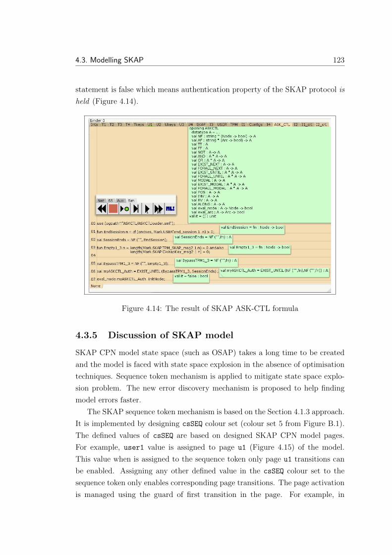
4.3. Modelling SKAP 123
statement is false which means authentication property of the SKAP protocol is
held (Figure 4.14).
Figure 4.14: The result of SKAP ASK-CTL formula
4.3.5 Discussion of SKAP model
SKAP CPN model state space (such as OSAP) takes a long time to be created
and the model is faced with state space explosion in the absence of optimisation
techniques. Sequence token mechanism is applied to mitigate state space explo-
sion problem. The new error discovery mechanism is proposed to help finding
model errors faster.
The SKAP sequence token mechanism is based on the Section 4.1.3 approach.
It is implemented by designing csSEQ colour set (colour set 5 from Figure B.1).
The defined values of csSEQ are based on designed SKAP CPN model pages.
For example, user1 value is assigned to page u1 (Figure 4.15) of the model.
This value when is assigned to the sequence token only page u1 transitions can
be enabled. Assigning any other defined value in the csSEQ colour set to the
sequence token only enables corresponding page transitions. The page activation
is managed using the guard of first transition in the page. For example, in

124 Chapter 4. Analysis of two TPM protocols
page u1 (Figure 4.15) the [vseq=user1] guard of transition ‘Start creating
exchange 1’ prevents enabling page transitions except when sequence token
value is user1. At the end of each page last transition determines the next active
page. In page u1, the last transition, ‘Send TPM SKAP() message’ evaluates
cNEXT USER14 value to find the next active page of CPN model. In SKAP model
the sequence token is integrated with sent or received messages between user,
TPM and intruder, but it is implemented in OSAP model using a global fusion
set.
vseq
vseq
vseq
vjo
vess
(vss,vpubkey)
vpubkey
vss
1`s
vpkh
Start creatingexchange 1
[vseq=user1]
Encrypt SessionSecret (S) using
RSA_OAEP
csSEQ
1`jo
csSEQ
csESS
Public key ofLoaded key
pk_pkh_user
1`pk_pkh_pub
csTPMKEY
Ss_user
csSS
1`pkh
csPKH
start session
IncsSEQ
csSKAP_MSG
In
s_user
pk_pkh_user
[vseq=user1]
Generate SessionSecret (S)
start exchangeone
JO
Enc. Session Secret
Send TPM_SKAP()message
pkhpkh_userpkh_user
sent TPM_SKAPmessage
OutOut
(vpkh,vess, cNEXT_USER1, cCONFIG)
1
1
1
1
Figure 4.15: The page of u1 module of the SKAP CPN model
In SKAP configurable model either a communication channel or an intruder
can be included in the model between user and TPM to review implementation
compatibility with protocol specifications or to verify authentication property.
In the proposed intruder CPN model of SKAP, Figure 4.13, in the first con-
figuration (cCONFIG=COMCH) intruder substitution transitions are excluded from
model. The sent packets from TPM or user pass through the communication
channel without any change. In this mode protocol implementation is verified.
The second configuration (cCONFIG=INTRUDER) includes intruder in the model.
4a constant value that when intruder is included in model the first intruder page sequencevalue (int1) is assigned to it. The first TPM page sequence value (tpm1) is assigned to thisconstant when intruder is excluded from model

4.4. Summary 125
The involved intruder in the message exchanges intercepts all the messages and
is able to save, edit and forward them. To activate these modes suitable val-
ues should be assigned to cCONFIG, cNEXT USER1, cNEXT TPM2, cNEXT USER3 and
cNEXT TPM4 values of Figure B.2 (lines 26 to 30). The application of configura-
bility in simulating each sub-model as a smaller part of model with less state
space nodes makes model validation process faster (during validation less places
and transitions are simulated).
The error-discovery mechanism is a new applied technique in modelling SKAP.
This technique by storing special tokens in specific places at the time of error
detection determines the error location in model and the reason of happening
error. This mechanism is designed following the approach of the Section 4.1.5.
It is implemented in SKAP CPN model using csERROR colour set (colour set 12
in Figure B.1). For any discovered error its corresponding value is selected from
the csERROR colour set. Then a token with the selected colour will be stored in
error global fusion set. After protocols termination, the stored token in error
fusion set determines where error has happened and why.
4.4 Summary
Usage of previous chapter CPN general modelling methodology to create OSAP
and SKAP protocols CPN models in this chapter and finding the previously re-
ported results by Chen and Ryan, demonstrates CPN and proposed methodology
applicability to model and analyse TPM security protocols and authentication
property. The applied approach analyses the authentication property by adding
a Dolev-Yao based intruder to the protocol model. ASK-CTL verifies the vio-
lation condition of the authentication property and produces consistent results
with Chen and Ryan’s work [36].
The proposed method to analyse the OSAP protocol has improved to model
SKAP by adding error-discovery and configurability mechanisms to the CPN
model. Error-discovery helps find errors faster, which is important in complex
models. The configurability assists with including or excluding an intruder (or
other parts) to or from the model. This facilitates model validation and com-
parison with its specifications. The provided flexibility by configurability makes
model simulation easier. After satisfying Chapter 4 first contribution by mod-
elling and verification of OSAP and SKAP authentication property then second

126 Chapter 4. Analysis of two TPM protocols
contribution by successful application of error-discovery mechanism, next chapter
focuses on modelling secrecy and two other properties.

Chapter 5
Security properties analysis in a
TPM-based protocol
The previous chapter focuses on analysing the authentication property of the
OSAP and SKAP protocols using CPN. This chapter concentrates on CPN
usage for analysing secrecy and two TPM-related security properties. These
properties are analysed in the Delaune proposed protocol [51].
The TPM-related security property term is introduced for the first time in
our research. These properties such as authentication or secrecy were not defined
earlier. This research has generally considered TPM-related security properties
as properties that are defined in trusted computing and systems that TPM is
operating on them. According to the interactions between TPMs and different
parts of the trusted computing system, these properties are defined differently.
Two samples of TPM-related security properties are defined and then analysed
in this section.
Delaune protocol can be considered as a simple oblivious transfer (OT) pro-
tocol. In an OT protocol, the sender transfers a part of potentially many parts of
information to a receiver, but remains oblivious as to what piece has been trans-
fered. OT was firstly introduced by Rabin [102] in 1981. In the first form of OT,
the sender sends a message with the probability 0.5 to the receiver. The sender
remains oblivious as to whether the receiver received the message or not. Rabin’s
OT scheme [102] is based on the RSA cryptosystem. The 1-2 OT (‘1 out of 2
oblivious transfer’) was developed by Even, Goldreich, and Lempel [58] in order
127

128 Chapter 5. Security properties analysis in a TPM-based protocol
to build protocols for secure multi-party computation later. The generalised ‘1
out of n oblivious transfer’ scheme is used where the user receives exactly one
database element without the server getting to know which element was queried,
and without the user knowing anything about the other elements that were not
retrieved. Crepeau has shown the 1-2 OT and Rabin’s OT are equivalent [47].
Because of the significance of the applications that can be built based on OT, it
is considered as a fundamental and important problem in cryptography. Delaune
[51] proposed protocol the initiator (Alice) sends two encrypted secrets to the
receiver (Bob) to decrypt only one of them while Bob, after opening one secret,
will not inform Alice what secret he has opened. Alice is not allowed to swap
the values of secrets after sending them to Bob.
Analysis of Delaune protocol security properties needs different intruder mod-
els with different abilities. Thus, a new intruder model is introduced whose
abilities are decryption and TPM PCR extension. The intruder uses his or her
abilities to try to violate the protocol secrecy property. While Delaune veri-
fies only secrecy property [51], CPN model is used to verify all three protocol
assumed properties.
In this chapter, after an introduction to the protocol and intruder model,
the protocol CPN model creation steps will be illustrated. Then, three protocol
properties including secrecy and two TPM-related properties will be formalised
and verified using ASK-CTL. The chapter is concluded with a summary.
5.1 Simple OT using TPM
The simple OT protocol is introduced by Delaune [51] to demonstrate TPM usage
in protocol design. There are two secrets –S1 and S2– that are only known by
Alice. Delaune has designed a protocol to ensure the following three properties:
1. Anybody, except Alice, for example Bob, can learn only one of the secrets.
Any effort to learn the second secret will be unsuccessful.
2. Alice commits to the secrets before knowing Bob’s choice. She cannot
change her decision according to the Bob’s decision.
3. Bob can open one of the secrets after Alice commits to them, without any
help from, or interaction with, Alice.

5.1. Simple OT using TPM 129
According to the first property definition, either S1 or S2 is visible for Bob.
Therefore, it is considered secrecy property. The other two properties are defined
specifically for the introduced OT protocol with TPM included in them. Thus,
in this research they are considered as TPM-related security property. Such
a protocol can easily be designed using a TPM. It is assumed that two keys,
K1 and K2 are already loaded in the TPM. The private and public parts of
these keys are pri(K1), pri(K2), pbk(K1) and pbk(K2). One of these keys is
locked to the h(u0, a1) (the initial value of PCR, u0, has been extended– the used
operation to assign a value to a PCR– with constant a1) and the other key is
locked to h(u0, a2) (the initial value of PCR, u0, has been extended with constant
a2).
Bob can use Certifykey command to obtain the certificate of these keys and
their lock values. After receiving the certificates, Alice uses the first public key,
pbk(K1), to encrypt the first secret (S1) and the second public key, pbk (K2)
to encrypt the second secret (S2), then sends both cipher texts to Bob. To open
the first secret, S1, Bob extends the PCR with a1 then decrypts the first cipher
text using Unbind TPM command. If Bob decides to open the second secret he
extends the PCR with the a2 then decrypts the second cipher text using Unbind
TPM command. Because PCR extension is not reversible, Bob cannot retrieve
both secrets. The steps of this protocol are shown in Figure 5.1.

130 Chapter 5. Security properties analysis in a TPM-based protocol
TPM Alice PCA Bob
(Intruder)
5)Open
either
S1 or S2
1) TPM_Certifykey(Args for key1)
TPM_Certifykey(Args for key2)
2) Cert.1, h(u0, a1)
Cert.2, h(u0, a2)
4) Epbk(K1)(S1), Epbk(K2)(S2)
3) Cert.1 and Cert.2
5b)Open
S2
TPM_Extend()
TPM_Extend() result
TPM_Unbind()
TPM_Unbind() result
5a)Open
S1
TPM_Extend()
TPM_Extend() result
TPM_Unbind()
TPM_Unbind() result
Figure 5.1: The simple oblivious transfer protocol steps
Bob could obtain both secrets by rebooting the TPM, as follows. First Bob
extends the PCR with a1 and uses Unbind with K1 then, after rebooting the
system, he extends the PCR with a2 and uses Unbind with K2. Delaune [51]
during her analysis has supposed that Bob cannot reboot the TPM. If Bob can
reboot the TPM, he can extend the PCR to another value so he can reveal the
other secret. The purpose of this chapter is to show how TPM-related properties
can be analysed so different assumptions does not affect our analysis.
5.2 Modelling simple oblivious transfer proto-
col
Modelling and analysis of the protocol CPN model is based on Figure 5.2 that
is created by adding more detail and a number of processes to the Figure 5.1
diagram.
In both models (Figure 5.1 and Figure 5.2) Bob is acting as a normal user
without any malicious action. To analyse protocol, Bob1 is able to perform
1In this protocol Bob is trying to open both S1 and S2 secrets. He acts as an intruder trying
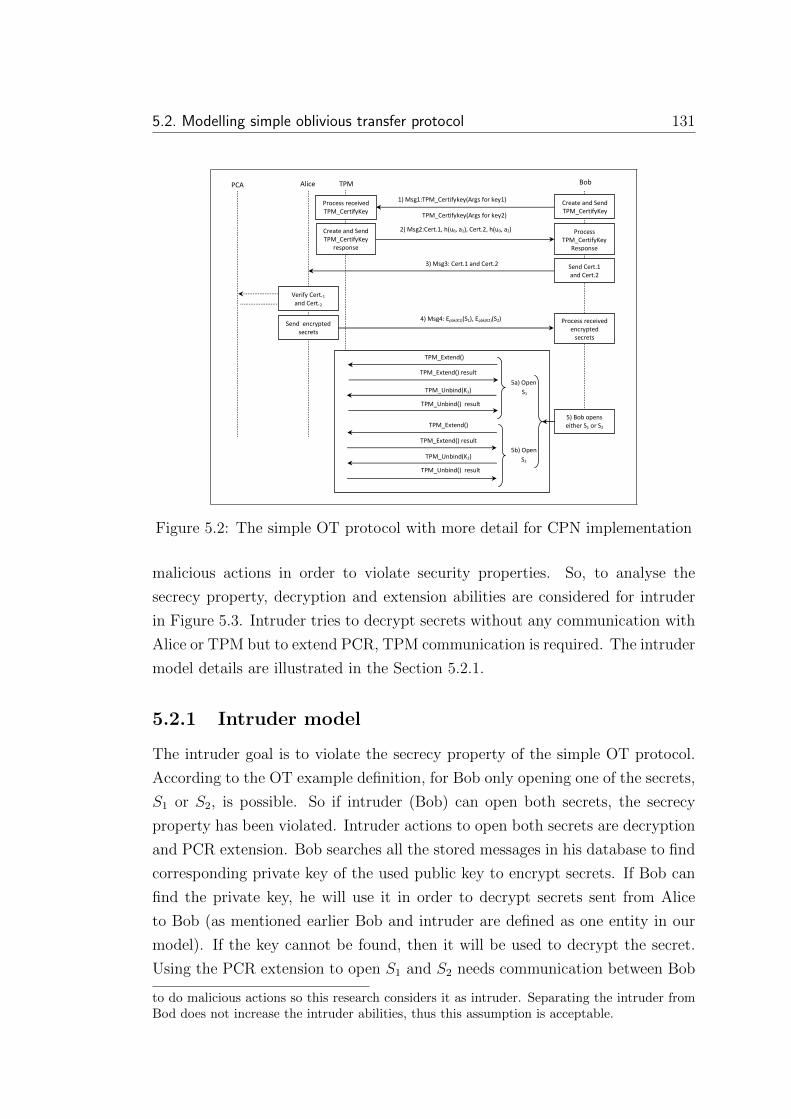
5.2. Modelling simple oblivious transfer protocol 131
Bob Alice PCA
1) Msg1:TPM_Certifykey(Args for key1)
TPM_Certifykey(Args for key2)
2) Msg2:Cert.1, h(u0, a1), Cert.2, h(u0, a2)
3) Msg3: Cert.1 and Cert.2
4) Msg4: Epbk(K1)(S1), Epbk(K2)(S2)
5) Bob opens
either S1 or S2
Create and Send
TPM_CertifyKey
Process received
TPM_CertifyKey
Create and Send
TPM_CertifyKey
response
Process
TPM_CertifyKey
Response
Send Cert.1
and Cert.2
Process received
encrypted
secrets
Verify Cert.1
and Cert.2
Send encrypted
secrets
TPM
5a) Open
S1
TPM_Extend()
TPM_Extend() result
TPM_Unbind(K1)
TPM_Unbind() result
5b) Open
S2
TPM_Extend()
TPM_Extend() result
TPM_Unbind(K2)
TPM_Unbind() result
Figure 5.2: The simple OT protocol with more detail for CPN implementation
malicious actions in order to violate security properties. So, to analyse the
secrecy property, decryption and extension abilities are considered for intruder
in Figure 5.3. Intruder tries to decrypt secrets without any communication with
Alice or TPM but to extend PCR, TPM communication is required. The intruder
model details are illustrated in the Section 5.2.1.
5.2.1 Intruder model
The intruder goal is to violate the secrecy property of the simple OT protocol.
According to the OT example definition, for Bob only opening one of the secrets,
S1 or S2, is possible. So if intruder (Bob) can open both secrets, the secrecy
property has been violated. Intruder actions to open both secrets are decryption
and PCR extension. Bob searches all the stored messages in his database to find
corresponding private key of the used public key to encrypt secrets. If Bob can
find the private key, he will use it in order to decrypt secrets sent from Alice
to Bob (as mentioned earlier Bob and intruder are defined as one entity in our
model). If the key cannot be found, then it will be used to decrypt the secret.
Using the PCR extension to open S1 and S2 needs communication between Bob
to do malicious actions so this research considers it as intruder. Separating the intruder fromBod does not increase the intruder abilities, thus this assumption is acceptable.
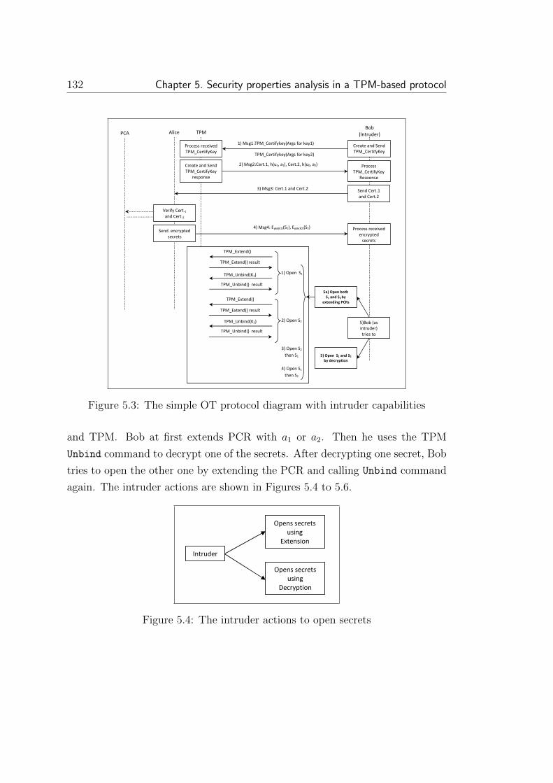
132 Chapter 5. Security properties analysis in a TPM-based protocol
Bob
(Intruder) Alice PCA
1) Msg1:TPM_Certifykey(Args for key1)
TPM_Certifykey(Args for key2)
2) Msg2:Cert.1, h(u0, a1), Cert.2, h(u0, a2)
3) Msg3: Cert.1 and Cert.2
4) Msg4: Epbk(K1)(S1), Epbk(K2)(S2)
5a) Open both
S1 and S2 by
extending PCRs
Create and Send
TPM_CertifyKey
Process received
TPM_CertifyKey
Create and Send
TPM_CertifyKey
response
Process
TPM_CertifyKey
Response
Send Cert.1
and Cert.2
Process received
encrypted
secrets
Verify Cert.1
and Cert.2
Send encrypted
secrets
TPM
5) Open S1 and S2
by decryption
5)Bob (as
intruder)
tries to
1) Open S1
TPM_Extend()
TPM_Extend() result
TPM_Unbind(K1)
TPM_Unbind() result
2) Open S2
TPM_Extend()
TPM_Extend() result
TPM_Unbind(K2)
TPM_Unbind() result
3) Open S2
then S1
4) Open S1
then S2
Figure 5.3: The simple OT protocol diagram with intruder capabilities
and TPM. Bob at first extends PCR with a1 or a2. Then he uses the TPM
Unbind command to decrypt one of the secrets. After decrypting one secret, Bob
tries to open the other one by extending the PCR and calling Unbind command
again. The intruder actions are shown in Figures 5.4 to 5.6.
Opens secrets
using
Extension
Opens secrets
using
Decryption
Intruder
Figure 5.4: The intruder actions to open secrets

5.3. Modelling simple OT protocol using CPN 133
Opens only S1
using extension
Opens only S2
using extension
Opens S1 then S2
using extension
Opens S2 then S1
using extension
Intruder
Figure 5.5: The intruder actions to open secrets using PCR extension
Bob searches
his DB to find
suitable
private key
Bob
DB
Bob tries to
decrypt
encrypted secrets
using fetched key
Figure 5.6: The intruder actions to open secrets using decryption
5.3 Modelling simple OT protocol using CPN
To create the protocol CPN model, the introduced methodology steps in Chapter
3 are followed. Figure 5.3 protocol steps are used in order to design the CPN
model pages. The model main page is shown in Figure 5.7.
The Start place initial marking is 1`start protocol to initiate the pro-
tocol from this place. At first the B I1 substitution transition is enabled. It
is the first Bob (or intruder) process that creates the TPM CertifyKey com-
mand, then sends it to the TPM. The created command token is stored in
the ‘sent TPM CertifyKey’ place. Next, the ‘comm channel1’ transition for-
wards the first protocol message from ‘sent TPM CertifyKey’ toward ‘rcvd

134 Chapter 5. Security properties analysis in a TPM-based protocol
Main Page
vmsg4vmsg4
vmsg3 vmsg3
vmsg2vmsg2
vmsg1 vmsg1
Extract finalerror and Bob_I
knowledge
sec_err_ext
Open secrets by decryption
Dec_sec
Open secretsby extending PCR
Extnd_PCR
B_I3
B_I3
Alice
Alice
TPM1
TPM1
B_I2
B_I2
B_I1
B_I1
commchannel4
commchannel3
commchannel2
commchannel1
Errors
csERROR
Bob_S2
csSECRET
Bob_S1
csSECRET
end_session
csSEQ
start extractingBob knowledge
csSEQ
start opening secrets by
extending PCR
csSEQ
start opening secrets by
decryption
csSEQ
ReceivedEncrypted
Secrets
csDblSecrets_Msg
Sent Encrypted
Secrets
csDblSecrets_Msg
receivedcertificates
csDbl_Cert_Msg
sentcertificates
csDbl_Cert_Msg
receivedTPM_CertifyKey
Response
csTPM_CertifyKey_Res_Msg
sentTPM_CertifyKey
Response
csTPM_CertifyKey_Res_Msg
rcvdTPM_CertifyKey
csTPM_CertifyKey_Msg
Start
1`start_protocol
csSEQ
sentTPM_CertifyKey
csTPM_CertifyKey_Msg B_I1
B_I2
TPM1
Alice
B_I3
Extnd_PCR
Dec_sec
sec_err_ext
Figure 5.7: The main CPN page of the simple OT protocol
TPM CertifyKey’. Then, the first protocol message is processed by the first TPM
substitution transition, TPM1. This substitution transition processes the received
TPM CertifyKey message, then stores the response in the ‘sent TPM CertifyKey
Response’ place as the second protocol message. Response message is processed
by second Bob process (B I2). Certificates of the stored keys in the TPM are
sent to Alice in the next step. They are processed and verified by Alice sub-
stitution transition. Certificate verification possibly needs communication with
the privacy certificate authority (PCA). The required communications are not
modelled in this analysis. Alice using pbk(K1) and pbk(K2) public keys en-
crypts both of the secrets and stores the result (Epbk(K1)(S1),Epbk(K2)(S2)) in
‘Sent Encrypted Secrets’ place. The stored message four, after forwarding
by ‘comm channel4’ will be processed by B I3. Then Bob tries to open both
of the secrets by either decrypting received messages or extending PCRs. Two
substitution transitions– ‘Open secrets by decryption’ and ‘Open secrets
by extending PCR’– are designed for this purpose.
At the end of the protocol, a sequence token with the endses marking is
stored in ‘start extracting Bob knowledge’ place. The last substitution
transition, ‘Extract final error and Bob I knowledge’, is designed for ver-
ification purposes. It collects intruder knowledge, protocol warnings, and errors
from different pages then stores them in Bob S1, Bob S2, and Errors places.
These places marking are used in the ASK-CTL formulas to verify different pro-

5.4. Protocol properties verification using ASK-CTL 135
tocol properties. The main page sub-pages, required colour sets and variables are
illustrated in Appendix 3. Three different pages are used to write the ASK-CTL
formulas and verify them that are illustrated in the next section.
5.4 Protocol properties verification using ASK-
CTL
The protocol secrecy violation property (1st condition) and other protocol prop-
erties (2nd and 3rd condition) are formalised using the ASK-CTL. To do so, the
following notations and predicates are defined:
1. let M be the set of all reachable marking of the sample protocol CPN
model;
2. M0 be the initial marking of the protocol CPN model;
3. [M0〉 be the set of all reachable markings from M0;
4. PMAINend session be a CPN place with the name of end session on the CPN
page called MAIN;
5. Marking(Mi, PMAINend session) represents the set of tokens at the CPN place
PMAINend session at a marking Mi where Mi ∈M0〉;
6. MOpen S1 = {Mi|Mi ∈ [M0〉∧|Marking(Mi, PMAINBob s1 )| > 0} is a set of marking
representing the situation whereby S1 has been opened successfully by Bob;
and
7. MOpen S2 = {Mi|Mi ∈ [M0〉∧|Marking(Mi, PMAINBob s2 )| > 0} is a set of marking
representing the situation whereby S2 has been opened successfully by Bob;
The main ASK-CTL operators used to formalise protocol properties when F1
and F2 are boolean formula are:
1. AND(F1, F2): This operator returns true if both F1 and F2 are hold.
2. OR(F1, F2): This operator returns true if either F1 or F2 or both are true.

136 Chapter 5. Security properties analysis in a TPM-based protocol
3. FORALL UNTIL(F1,F2): This operator returns true if for all the paths from
a given marking (e.g., M0) F1 holds in every marking until it reaches a
marking whereby F2 holds.
4. POS(F1): This operator is equivalent to EXIST UNTIL(TRUE, F1). It re-
turns true if there exists a path starting from a given marking (e.g., M0)
that finally reaches to another marking whereby F1 holds.
Having described the above notations, predicates and operators, the protocol
properties can now formally assert.
5.4.1 Verification of first protocol property (secrecy)
The protocol secrecy property holds when there is no marking in the state space
where both S1 and S2 are opened. So the result of Formula (5.1), starting from
M0, is false. The written ML code for the ASK-CTL formula and its result
is demonstrated in Figures 5.8 and 5.9. If the result of Figure 5.8 be true then
intruder has opened both S1 and S2. This marking can be removed by redesigning
the protocol.
Results : The state space of the model is generated, and the ASK-CTL state-
ment for Formula (5.1) is written (Figure 5.8) and executed. The model shows
that the ASK-CTL statement (5.8) is false (Figure 5.9), which means that the
first protocol property (secrecy property) holds .
POS(MOpen s1 ∧ MOpen s2) (5.1)
00
01
02
03
04
use (ogpath^"ASKCTL/ASKCTLloader.sml");
fun Open_S1_S2 n = cf(s1, Mark.MAIN'Bob_S1 1 n) > 0 andalso cf(s2, Mark.MAIN'Bob_S2 1 n) >0;
val Opened_S1_and_S2 = POS(NF ("", Open_S1_S2));
eval_node Opened_S1_and_S2 InitNode;
Figure 5.8: The ASK-CTL formula of 1st condition (secrecy property)

5.4. Protocol properties verification using ASK-CTL 137
Figure 5.9: The result of ASK-CTL formula for the first condition
5.4.2 Verification of second protocol property
The second protocol condition (Alice commits to the secrets before knowing
Bob’s choice) is verified by evaluating two sub-conditions, the former is before
the marking that Alice commits on S1 and S2 and the latter is after the Alice
commitment marking on S1 and S2. Before Alice commits on S1 and S2 for all
the markings starting from initial marking (e.g., M0), S1 and S2 are not opened.
Thus, the result of Formula (5.2) is true. After Alice’s commitment on S1 and
S2 for all the markings, Alice does not change her commitment until Bob opens
S1 or S2. Therefore, the result of Formula 5.3 will be true. The second protocol
condition holds if both sub-conditions (5.2 and 5.3 formulas) are true.
1. MSecrets Committed = {Mi|Mi ∈ [M0〉 ∧ |Marking(Mi, PAlicesecret commitment)| > 0}
is a set of marking representing the situation whereby Alice has committed
to the secrets; and
2. MChange in commitment = {Mi|Mi ∈ [M0〉 ∧ |Marking(Mi, PAlicesecret commitment)| 6=
1} is a set of marking representing the situation whereby Alice has changed
her commitment to the secrets.
FORALL UNTIL((¬(MOpen s1 ∧ MOpen s2)),MSecrets Committed) (5.2)
FORALL UNTIL(¬MChange in commitment, (MOpen s1 ∨ MOpen s2)) (5.3)
The written ML code for the ASK-CTL formula and its result are demonstrated
in Figures 5.10 and 5.11. As the initial marking for the second sub-condition is

138 Chapter 5. Security properties analysis in a TPM-based protocol
not InitNode, thus the state space function of line 18 in Figure (5.10) is used to
find the initial marking for second sub-condition.
Results : The state space of the model is generated and the ASK-CTL state-
ments for Formulas 5.2 and 5.3 are written in Figure 5.10) lines 8 and 14. After
executing both ASK-CTL formulae, the result in Figure 5.11 shows, that the
ASK-CTL statements are true, which means that the second protocol property
holds .
SearchNodes(EntireGraph, fn n => (cf (commited, Mark.Alice'secret_commitment 1 n) > 0), NoLimit, fn n => ((cf(s1, Mark.MAIN'Bob_S1 1 n) > 0) orelse (cf(s2, Mark.MAIN'Bob_S2 1 n) > 0)), [], op ::);
fun cmtlength n = length (Mark.Alice'secret_commitment 1 n) =1;
val no_change_in_alice_commitment = NF ("", cmtlength);
val s1_or_s2_opened = OR (s1_opened, s2_opened) ;
val second_sub_cond = FORALL_UNTIL(no_change_in_alice_commitment, s1_or_s2_opened) ;
eval_node second_sub_cond 88;
use (ogpath^"ASKCTL/ASKCTLloader.sml");
fun commitment n = cf (commited, Mark.Alice'secret_commitment 1 n) > 0;
val secrets_commited = NF ("", commitment);
fun open_s1 n = cf (s1, Mark.MAIN'Bob_S1 1 n) > 0;
val s1_opened = NF ("s1 opened", open_s1);
fun open_s2 n = cf(s2, Mark.MAIN'Bob_S2 1 n) > 0;
val s2_opened = NF ("s2 opened", open_s2);
val s1_and_s2_not_opened = NOT(AND(s1_opened, s2_opened));
val first_sub_cond = FORALL_UNTIL(s1_and_s2_not_opened, secrets_commited) ;
eval_node first_sub_cond InitNode;
val second_property = AND(first_sub_cond, second_sub_cond);
00
01
02
03
04
05
06
07
08
09
10
11
12
13
14
15
16
17
18
Figure 5.10: The ML code for the second condition ASK-CTL formula
5.4.3 Verification of third protocol property
According to the last protocol property, Bob can open one of the secrets without
any interaction with Alice after she has committed to the secrets. In order to
verify the property, at first the ASK-CTL function in line 18 of Figure 5.12 is

5.4. Protocol properties verification using ASK-CTL 139
Figure 5.11: The result of ASK-CTL formula for the second condition
applied to find the marking where Alice commits on S1 and S2. Then, from the
commitment marking till the marking that either secret S1 or S2 is opened, for all
the paths if Alice does not change her commitment and Bob does not start a new
interaction with Alice the third condition (Formula 5.4) will hold . To illustrate
the last condition with more detail the following functions and predicates are
defined:
1. Minteraction ended = {Mi|Mi ∈ [M0〉∧|Marking(Mi = ended, PAliceinteract bob ended)| >
0} is a set of marking representing the situation whereby Alice has ended
interaction with Bob.
2. Mno interaction started = {Mi|Mi ∈ [M0〉∧|Marking(Mi=started, PAliceinteract bob ended)| =
0} is a set of marking representing the situation whereby Alice has not
started new interaction with Bob.
3. Mcommitted interact ended = AND(Msecrets committed,Minteraction ended) is a mark-
ing that Alice has committed to the secrets and her interaction with Bob
has ended.
4. Mcommitted ended not started = AND(Mcommitted interact ended,Mno interaction started)
is a marking that Alice has committed to the secrets and has ended her
interaction with Bob and she has never started a new interaction with Bob.

140 Chapter 5. Security properties analysis in a TPM-based protocol
5. Ms1 or s2 opened = OR(MOpen S1,MOpen S2) is a marking that Bob has opened
either S1 or S2.
Having described the above notations, predicates and operator, it is now
possible to formally assert that the third condition of the OT protocol holds
if the ASK-CTL statement (5.4) returns true. The written ML code for the
ASK-CTL formula and its result are demonstrated in Figures 5.12 and 5.13.
Results : The state space of the model is generated and the ASK-CTL state-
ment for Formula (5.4) is written in Figure 5.12 and executed. The result shows
that the ASK-CTL statement in line 15 of Figure 5.12 is true (Figure 5.13),
which means that the third protocol property holds .
FORALL UNTIL(Mcommitted ended not started,Ms1 or s2 opened) (5.4)

5.4. Protocol properties verification using ASK-CTL 141
00
01
02
03
04
05
06
07
08
09
10
11
12
13
14
15
16
17
18
fun end_interaction n = cf (ended, Mark.Alice'interact_bob_ended 1 n) > 0;
val interaction_ended = NF ("", end_interaction);
fun no_interaction n = cf (started, Mark.Alice'interact_bob_ended 1 n) = 0;
val no_interaction_started = NF ("", no_interaction);
val commited_interact_ended = AND (secrets_commited, interaction_ended) ;
val commited_ended_not_started = AND (commited_interact_ended, no_interaction_started);
fun open_s1 n = cf (s1, Mark.MAIN'Bob_S1 1 n) > 0;
val s1_opened = NF ("", open_s1);
fun open_s2 n = cf (s2, Mark.MAIN'Bob_S2 1 n) > 0;
val s2_opened = NF ("", open_s2);
val s1_or_s2_opened = OR (s1_opened, s2_opened);
val third_property = FORALL_UNTIL(commited_ended_not_started, s1_or_s2_opened) ;
eval_node third_property 88;
use (ogpath^"ASKCTL/ASKCTLloader.sml");
fun commitment n = cf (commited, Mark.Alice'secret_commitment 1 n) > 0;
val secrets_commited = NF ("", commitment);
SearchNodes(EntireGraph, fn n => (cf (commited, Mark.Alice'secret_commitment 1 n) > 0), NoLimit, fn n => ((cf(s1, Mark.MAIN'Bob_S1 1 n) > 0) orelse (cf(s2, Mark.MAIN'Bob_S2 1 n) > 0)), [], op ::);
Figure 5.12: The ML code for the third condition ASK-CTL formula
Figure 5.13: The result of ASK-CTL formula for the third condition

142 Chapter 5. Security properties analysis in a TPM-based protocol
5.5 Discussion
In this chapter, the methodology proposed in Chapter 3 is applied to make
the protocol CPN model faster. The designer knows what steps are required
to be followed and therefore it is easier to start a modelling process then that
process can finish faster. The intruder model used for Chapter 3 methodology
is designed in order to analyse only authentication property. Thus, this chapter
has proposed a different intruder compared with Chapter 3 intruder model to
analyse secrecy property. As the proposed intruder model has not been available,
its design is more time consuming in comparison with other parts of the CPN
model. It is better to include the secrecy property analysis intruder model in the
methodology in the future.
Analysis of TPM-related security properties is mainly based on including
requirements in CPN model then writing suitable ASK-CTL formula. These
properties analysis does not require any intruder, therefore a number of modelling
steps, related to intruder model creation, are ignored. This type of model is not
included in the methodology. In future this type of model should be included
in the methodology section. The verification step for secrecy and TPM-related
security properties is similar to authentication. The formula is written using
ASK-CTL then is verified using CPN/Tools state space.
Analysis of Delaune OT protocol secrecy property using other special purpose
analysis tools such as ProVerif, is feasible. However, introduced TPM-Related
security properties cannot be analysed using special purpose tools designed in
order to analyse pre-defined security properties. General purpose tools such as
CPN are a suitable analysis tool in order to analyse user-defined properties, such
as the analysed properties in this chapter.
5.6 Summary
In this chapter the Delaune OT TPM-based protocol CPN model was presented.
This model was applied in order to analyse secrecy and two TPM-related security
properties. The secrecy property was successfully analysed by designing a new
intruder model, which is integrated with one of the protocol agents in order to
fulfill the first contribution of this chapter.
The two other chapter contributions to design new model for two TPM-
related security properties then writing two new ASK-CTL formulas to verify

5.6. Summary 143
the properties, were successfully satisfied by designing a new model suitable to
analyse TPM-related properties then writing two ASK-CTL formulas that can
verify the properties in the CPN/Tools state space environment. The successful
CPN usage to analyse OT properties demonstrates how it can be applied to
analyse variety of attributes (authentication, secrecy and OT properties). This
flexibility makes CPN a useful formal method to analyse security properties.

144 Chapter 5. Security properties analysis in a TPM-based protocol

Chapter 6
Conclusion and future work
This chapter summarises the thesis result, discusses a few limitations and finally
introduces possible future works. First it is illustrated how research goals are
fulfilled and are covered in different chapters. Then it is discussed a few research
limitations. Finally, possible future work and research is listed.
6.1 Summary
The main contribution of this research is to demonstrate the applicability of
Coloured Petri Nets in the modelling and verification of security properties in
real-world protocols, specifically trusted-computing protocols. The Al-Azzoni
NSPK authentication protocol implementation is in Design/CPN which is not
supported by its developers at the moment. This research re-implements Al-
Azzoni CPN model of NSPK authentication protocol in CPN/Tools after apply-
ing minor changes in the original CPN model in Design/CPN tool. The NSPK
modelling experiences are used in proposing a general methodology to create
protocol CPN model. Then the designed case studies with OSAP and SKAP
based on the proposed methodology are able to arrive at the same conclusion
reported by Chen and Ryan [36] and demonstrate the methodology correctness.
Our initial simple modelling approach used with OSAP is improved in our SKAP
analysis by proposing new error-discovery mechanism, improving the Al-Azzoni’s
sequence token approach and applying known configurable model mechanism in
order to make the approach more usable. The OSAP and SKAP protocol and
145

146 Chapter 6. Conclusion and future work
intruder models are applied to analyse the authentication property of both pro-
tocols.
Analysis of Delaune simple OT protocol [51] verifies secrecy and two more
protocol properties. Secrecy analysis is able to arrive at the same conclusion
reported by Delaune [51]. Analysis of other OT protocol properties demonstrates
how non-security properties can be modelled and verified separately in a protocol.
CPN as a general purpose modelling language can be used to combine security
properties of security protocols with security aspects of other parts of system.
In systems such as trusted computing where different platforms are cooperating
with each other, this can be a suitable choice for analysing the system. The
analysis of three different properties of simple OT protocol demonstrates this
applicability.
The introduced research contributions (Section 1.1) are specifically covered
as follows:
1. Contribution 1: Covered in the Chapter 3 by proposing a general method-
ology to create CPN model of TPM protocols.
2. Contribution 2: Achieved in Chapters 4 and 5 by modelling authentica-
tion and secrecy properties.
3. Contribution 3: Fulfilled for security properties in Chapters 4 and 5.
Two non-security properties have been analysed in Chapter 5 to completely
cover the third goal.
6.2 Limitations
In the created models with CPN/Tools, any changes in protocol and its message
structure can cause significant cascaded changes in the CPN model. However,
this strong connection between parts helps designers to be more familiar with
the protocol specification. This dependency can be reduced by designing a more
general approach and more general components. Another CPN usage drawback
is state space explosion. The possibility of explosion cannot be predicted till the
end of protocol modelling.

6.3. Future work 147
6.3 Future work
As future work, the general methodology can be expanded to cover more in-
truder models and security properties such as integrity, trust, robustness and
availability.
Designing and implementing variant colorsets that can be used for modelling
different messages with different colorsets is another research area. Future work
could investigate adding a number of components to the CPN/Tools to imple-
ment general purpose variant colorset.
In this research the intruder abilities are based on stored knowledge in a
database and a number of defined fixed actions (extension and decryption). As
future work a rule-base and an inference engine can be designed for intruder
(specially used intruder for secrecy analysis). The inference engine based on
rule-base rules can generate new rules and adds them to the intruder knowledge
to make the intruder more powerful.
The error-discovery method can be extended to an error-handling mechanism
that makes the behaviour of model entities more intelligent. The new intelligent
error-handling mechanism based on different errors forces the model to follow dif-
ferent paths, be terminated or initialised. If there is any error that its happening
is an evidence for protocol violation by intruder this mechanism can manage it by
user or TPM as well. Special error-handling mechanisms can be designed for the
intruder to take advantage of the occurred errors in the model. The intelligent
intruder can do different actions based on occurred errors in user or TPM side.
It can hide intruder errors from the user or TPM.
The existing configurability mechanism can be improved by designing more
configurations (CPN sub-models) that include or exclude different transitions,
pages and substitution transitions to or from the model. In the current config-
urability mechanism the initial marking of places does not change in different
configurations. Designing an approach that can apply different markings and
configurations at the same time can be another extension for the model.
A few more suggested future works are:
1. Analysis of a combination of different properties in different platforms.
2. Applying the secrecy intruder model for other protocols.
3. Making the proposed intruder model and database of OT protocol more
general.

148 Chapter 6. Conclusion and future work
4. Developing a library of CPN models for various intruder models and secu-
rity properties to facilitate analysis process.
5. Analysis of more protocol properties.
6. Analysis of a variety of security properties using different adversary models
then updating the methodology considering new experiences.
7. Improving error-discovery by adding error-handling and error-recovery to
different parts of the model.
8. Finding methods for predicting state space explosion.

Appendix A
Appendix: OSAP CPN model
The required steps for modelling the OSAP protocol and the main model pages
are illustrated in the Section 4.2. This appendix provides more detail about the
OSAP model colour sets, variables and CPN pages. The list of all defined colour
sets and declared variables based on them is shown in Figures A.1 and A.2.
149

150 Appendix A. Appendix: OSAP CPN model
The colour sets 1 to 4 (in Figure A.1) are CPN/Tools standard colour sets.
The user-defined colour sets are illustrated as follows:
01 colset csTERMS = with null | ah |
ahi | no_osap | ne | ne_osap |
ne_osap1 | no | ne1 | ni1 |
pkh_pub | pkhi | keyblob |
keyblobi | ad_pkh_pub | newauth;
This colour set defines all the terms used in the protocol. These terms are
the components of each sent and received message. No other terms can be used.
The existence of letter‘i’ at the end of the term, indicates that the term has been
created by the intruder.
02 colset csATTACK = with posattack | negattack;
The csATTACK colour set determines whether an attack has occurred or not.
When an attack has occurred a token with the value of posattack is put in
a designated place. When no attack has occurred a token with the value of
negattack is put in the designed place.
03 colset csSEQ = with user1 | user2 |
user3 | user4 | user41 | user42 |
user43 | user5 | int1 | int2 | int3 |
int4 | intx3 | tpm1 |tpm2 | tpm3 |
tpm4 | tpm5 | bypass1 |
bypass2 | endses | terminateses;
The state space explosion is one of the most important problems of modelling
protocols by CPN. To prevent this problem csSEQ colour set is designed to
define which transitions can be run in any state. When in a typical state the
user1 transition should be enabled, all the other transitions will be deactivated
to decrease the state space nodes.
04 colset csAUTH_HANDLE = subset csTERMS with [ah,ahi];

151
This colour set defines which authorisation handles can be created or used. The
ah is used by TPM and the user. The ahi is another authorisation handle that
is faked by the intruder.
05 colset csNONCE = subset csTERMS with [no_osap,
ne, ne_osap, no, ne1, ni1];
This colour set defines all the nonces that are used or created by the user, TPM
and intruder.
06 colset csPUBKH = subset csTERMS with [ pkhi, pkh_pub];
This colour set defines the public key handle used by the user, TPM and intruder.
07 colset csAUTH_DATA = subset csTERMS with [ad_pkh_pub,newauth];
This colour set defines the authorisation data.
08 colset csOSAP_MSG = product
csPUBKH * csNONCE;
In the first protocol exchange, shown in Figure 4.4, sent message format is defined
by this colour set.
09 colset csOSAP_RESPONSE = product
csAUTH_HANDLE * csNONCE * csNONCE;
The format of the TPM response to the OSAP message (the 2nd interchange of
Figure 4.4) is defined by the csOSAP RESPONSE.
10 colset csSHARED_SECRET = product csAUTH_DATA * csNONCE * csNONCE;
The TPM and the user are both able to create a shared secret. To define the
format of the secret csSHARED SECRET colour set is used .
11 colset csKEYBLOB = product
csSHARED_SECRET * csAUTH_DATA;

152 Appendix A. Appendix: OSAP CPN model
This colour set defines the keyblob structure as the product of shared secret and
authData structures.
12 colset csXOR_OUTPUT = product csSHARED_SECRET * csNONCE *
csAUTH_DATA;
This is a colour set designed to temporarily store the result of the XOR function.
13 colset csHMAC_OUTPUT = product csSHARED_SECRET * csNONCE *
csNONCE;
This is a colour set designed to temporarily store the result of the HMAC func-
tion.
14 colset csWRAPKEY_INPUT = product csAUTH_HANDLE *
csPUBKH * csNONCE * csXOR_OUTPUT;
This colour set stores all the inputs of the TPM CreateWrapKey function.
15 colset csWRAPKEY_MSG = product csWRAPKEY_INPUT * csHMAC_OUTPUT;
The message sent in exchange number 3 of the protocol is sent by the user to
the TPM and is stored in this colour set.
16 colset csWRAPKEY_RESPONSE = product csKEYBLOB *
csNONCE * csHMAC_OUTPUT;
The response of the TPM to TPM CreatWrapKey function is stored in a message
of type csWRAPKEY RESPONSE.
17 colset csINTDB = union
fipkh : csPUBKH +
finonce : csNONCE +
fiah : csAUTH_HANDLE +
fixor_output : csXOR_OUTPUT +
fihmac_output : csHMAC_OUTPUT +
fikeyblob : csKEYBLOB +

153
fiosap_msg : csOSAP_MSG +
fiosap_res : csOSAP_RESPONSE +
fiwrapkey_msg : csWRAPKEY_MSG +
fiwrapkey_rsp : csWRAPKEY_RESPONSE +
fiwrapkey_input : csWRAPKEY_INPUT +
fiss : csSHARED_SECRET +
fiauthdata : csAUTH_DATA;
The intruder has a database where stores its knowledge. This database is a
location to accumulate all the intercepted messages by intruder. It also stores
the initial knowledge of the intruder. The colour set csINTDB is designed for this
purpose. The initial value of intruder’s database is shown in Figure A.3. In this
figure the part 1`fiauth handle(ahi) means that one token with value of ahi
should be put in the fiauth handle field of intruder’s database. The other fields
have the similar meaning. For example, 1`finonce(ni1) means that a nonce
with value of ni1 is put in the finonce field of the database.

154 Appendix A. Appendix: OSAP CPN model
01 colset csTERMS = with null | ah |
ahi | no_osap | ne | ne_osap |
ne_osap1 | no | ne1 | ni1 |
pkh_pub | pkhi | keyblob |
keyblobi | ad_pkh_pub | newauth;
02 colset csATTACK = with posattack | negattack;
03 colset csSEQ = with user1 | user2 |
user3 | user4 | user41 | user42 |
user43 | user5 | int1 | int2 | int3 |
int4 | intx3 | tpm1 |tpm2 | tpm3 |
tpm4 | tpm5 | bypass1 |
bypass2 | endses | terminateses;
04 colset csAUTH_HANDLE = subset csTERMS with [ah,ahi];
05 colset csNONCE = subset csTERMS with [no_osap,
ne, ne_osap, no, ne1, ni1];
06 colset csPUBKH = subset csTERMS with [ pkhi, pkh_pub];
07 colset csAUTH_DATA = subset csTERMS with [ad_pkh_pub,newauth];
08 colset csOSAP_MSG = product
csPUBKH * csNONCE;
09 colset csOSAP_RESPONSE = product
csAUTH_HANDLE * csNONCE * csNONCE;
10 colset csSHARED_SECRET = product
csAUTH_DATA * csNONCE * csNONCE;
11 colset csKEYBLOB = product
csSHARED_SECRET * csAUTH_DATA;
12 colset csXOR_OUTPUT = product
csSHARED_SECRET * csNONCE * csAUTH_DATA;
13 colset csHMAC_OUTPUT = product
csSHARED_SECRET * csNONCE * csNONCE;
14 colset csWRAPKEY_INPUT = product
csAUTH_HANDLE * csPUBKH *
csNONCE * csXOR_OUTPUT;
15 colset csWRAPKEY_MSG = product
csWRAPKEY_INPUT * csHMAC_OUTPUT;
16 colset csWRAPKEY_RESPONSE = product
csKEYBLOB * csNONCE * csHMAC_OUTPUT;
17 colset csINTDB = union
fipkh : csPUBKH +
finonce : csNONCE +
fiah : csAUTH_HANDLE +
fixor_output : csXOR_OUTPUT +
fihmac_output : csHMAC_OUTPUT +
fikeyblob : csKEYBLOB +
fiosap_msg : csOSAP_MSG +
fiosap_res : csOSAP_RESPONSE +
fiwrapkey_msg : csWRAPKEY_MSG +
fiwrapkey_rsp : csWRAPKEY_RESPONSE +
fiwrapkey_input : csWRAPKEY_INPUT +
fiss : csSHARED_SECRET +
fiauthdata : csAUTH_DATA;
Figure A.1: The colorsets of OSAP model

155
var e : UNIT;
var vseq, vseq1, vseq2 : csSEQ;
var tmpstr : STRING;
var vosap_res : csOSAP_RESPONSE;
var vne, vne1, vnonce1,
vnonce2 , vne_osap,
vne_osap1, vno,
vno_osap : csNONCE;
var vah : csAUTH_HANDLE;
var vosap_msg : csOSAP_MSG;
var vauthdata, vnewauth : csAUTH_DATA;
var vss: csSHARED_SECRET;
var vxor_output : csXOR_OUTPUT;
var vwrapkey_input,
vwrapkey_output: csWRAPKEY_INPUT;
var vwrapkey_msg: csWRAPKEY_MSG;
var vwrapkey_rsp : csWRAPKEY_RESPONSE;
var vhmac_output, vhmac_user,
vhmac_tpm: csHMAC_OUTPUT;
var vkeyblob:csKEYBLOB;
var vpkh, vpkhu, vkh : csPUBKH;
Figure A.2: The list of OSAP model variables
1‘fipkh(pkh_pub) ++
1‘finonce(ni1) ++
1‘fiauthdata(ad_pkh_pub)
Figure A.3: The initial value of the intruder database

156 Appendix A. Appendix: OSAP CPN model
A.1 User substitution transitions
There are a number of transitions and substitution transitions designed to process
messages sent and received by the user. The TPM OSAP(pkh, no osap) substi-
tution transition (page U1 in Figure 4.5) creates the TPM OSAP (pkh, no osap)
message then sends it to the TPM. The ‘Process TPM OSAP Response’ substi-
tution transition (page U2) processes TPM answer to TPM OSAP (pkh, no osap)
command. Then ‘Create Shared Secret User’ (page U3) produces session
shared secret for user usage. The TPM CreateWrapKey(...) ((page U4)) gener-
ates TPM CreateWrapKey(...) command for sending toward TPM in the next
step. The ‘Process TPM CreateWrapKey(...) Response’ substitution tran-
sition(page U5) is the last user process. The next sub-sections illustrate user
pages with more detail.
A.1.1 Modelling TPM OSAP(pkh, no osap) sub. transition
The CPN model of TPM OSAP(pkh, no osap) substitution transition is shown in
Figure A.4. The TPM OSAP transition needs three tokens from the no osap user,
pkh user and ‘call TPM OSAP’ places to be run. The token of the ‘call
TPM OSAP’ place is provided from the ‘Start Session 1’ in the upper page of
the model. This token is the sequence token that will be passed through different
transitions to determine the correct sequence of the protocol. The value of this
token is compared by a specific constant (eg. user1) in the guard [vseq=user1]
of transition TPM OSAP. When the value of this guard is true, the transition can
be run. After running the transition TPM OSAP, sequence token moves to the
place Seq.
Other two required tokens, no osap and pkh user, are stored in no osap user
and pkh user places as the initial value. This assumption is acceptable because
the no osap is a nonce that is created by the user and the pkh user is a value that
is known publicly. These two tokens are returned by double arcs to their initial
places after the TPM OSAP transition is enabled to provide these tokens for other
stages of the protocol when the user needs them again. As no osap is used by the
user to create the shared secret and to make the model as simple and readable
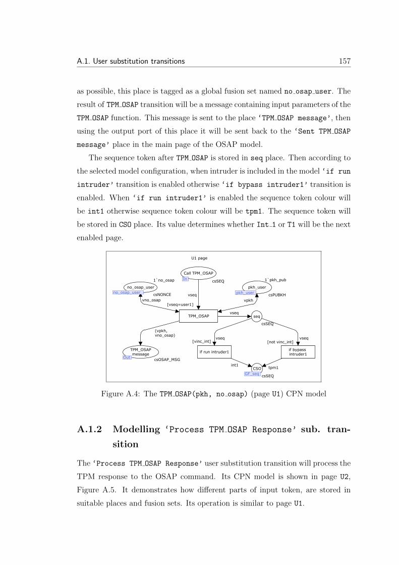
A.1. User substitution transitions 157
as possible, this place is tagged as a global fusion set named no osap user. The
result of TPM OSAP transition will be a message containing input parameters of the
TPM OSAP function. This message is sent to the place ‘TPM OSAP message’, then
using the output port of this place it will be sent back to the ‘Sent TPM OSAP
message’ place in the main page of the OSAP model.
The sequence token after TPM OSAP is stored in seq place. Then according to
the selected model configuration, when intruder is included in the model ‘if run
intruder’ transition is enabled otherwise ‘if bypass intruder1’ transition is
enabled. When ‘if run intruder1’ is enabled the sequence token colour will
be int1 otherwise sequence token colour will be tpm1. The sequence token will
be stored in CSO place. Its value determines whether Int 1 or T1 will be the next
enabled page.
vseq vseq
vseq
tpm1int1
vpkh
(vpkh,vno_osap)
vno_osap
vseq
[vinc_int]
TPM_OSAP
[vseq=user1]
seq
csSEQ
pkh_user
pkh_user
1`pkh_pub
csPUBKH
csSEQ
TPM_OSAPmessage
OutcsOSAP_MSG
no_osap_user
no_osap_user
1`no_osap
csNONCE
Call TPM_OSAP
IncsSEQ
In
no_osap_user pkh_user
Out
if bypass intruder1
CSO
GF_seqGF_seq
U1 page
[not vinc_int]
if run intruder1
Figure A.4: The TPM OSAP(pkh, no osap) (page U1) CPN model
A.1.2 Modelling ‘Process TPM OSAP Response’ sub. tran-
sition
The ‘Process TPM OSAP Response’ user substitution transition will process the
TPM response to the OSAP command. Its CPN model is shown in page U2,
Figure A.5. It demonstrates how different parts of input token, are stored in
suitable places and fusion sets. Its operation is similar to page U1.

158 Appendix A. Appendix: OSAP CPN model
user3vseq
e
(vah,vne,vne_osap)
vne_osap vnevah
Process TPM_OSAPResponse
[vseq=user2]
CSO
GF_seqcsSEQ
CSIGF_seq
csSEQ
ne_osap_user
ne_osap_usercsNONCE
ne_user
ne_usercsNONCE
ah_user
ah_user
csAUTH_HANDLE
ReceivedTPM_OSAP ResponseIn
csOSAP_RESPONSE
Start SharedSecret
OutUNIT
Out
In
ah_user ne_userne_osap_user
GF_seq GF_seq
Figure A.5: The ‘Process TPM OSAP Response’ (page U2) CPN model.
The next step is creating the shared secret by user. The ‘Create Shared
Secret User’, Figure A.6, substitution transition does this.
A.1.3 Modelling ‘Create Shared Secret User’ sub. tran-
sition
This substitution transition (Figure A.6) generates the shared secret and puts it
in the ‘shared secret user’ place. The shared secret is generated based on
content of ‘authdata pkh user’, ne osap user and no osap user places. The
CSI place is used to move the current state token of model to the ‘generate
shared secret user’. The CSO place stores the next state of model sequence
token, user41, in the GF seq global fusion set. The current sequence of the pro-
tocol is moved to the ‘generate shared secret user’ by ‘Start creating
Shared Secret’ place and then will be moved to the next transitions by ‘Start
Seq 3’.
A.1.4 Modelling TPM CreateWrapKey(...) sub. transition
TPM CreateWrapKey(...) (page U4) is the next substitution transition from the
user side to be run. It produces the following message:
TPM CreateWrapKey(ah, pkh, no, ..., SHA1(S, ne)⊕newauth), hmacS(ne, no, ...)

A.1. User substitution transitions 159
user41
()
()
vne_osapvauthdata vno_osap
GENERATE SHARED SECRET USER
[vseq=user3]
CSOGF_seq
csSEQ
CSIGF_seq
csSEQ
ne_osap_user
ne_osap_user csNONCE
authdata_pkhuser
AD_Pkh_User
1`ad_pkh_pub
csAUTH_DATA
shared secretuser
shared_secret_user csSHARED_SECRET
no_osap_user
no_osap_user
1`no_osap
csNONCE
Start creatingShared Secret
InUNIT
UNIT
In
no_osap_user
shared_secret_user
AD_Pkh_User ne_osap_user
GF_seq GF_seq
U3 page
vseq (vauthdata, vne_osap,vno_osap)
Start Seq3
OutOut
Figure A.6: The ‘Create Shared Secret User’ (page U3) CPN model
Figure A.7 demonstrates the substitution transition whole model.
To simplify modelling, Create XOR substitution transition (page U4 1), pro-
duces the
SHA1(S, ne)⊕ newauth
part of message. Its model is designed in page U4 1, Figure A.8. In page U4 1,
‘Create XOR WrapKey’ transition fetches the required tokens from ‘new auth’,
‘SHARED SECRET USER’ and ‘ne user’ places. The created result will be sent
to the ‘xor output’ place then using the output port the result is sent back to
the ‘xor result’ place in page U4 and will be used later.
The ‘Prepare TPM CreateWrapKey’ substitution transition in Figure A.7,
(complete model is available in Figure A.9), produces
TPM CreateWrapKey(ah, pkh, no, ..., SHA1(S, ne)⊕ newauth)
part of message. The result of Create XOR is sent to ‘Prepare TPM CreateWrapKey’,
using the ‘xor result’ input port. In Figure A.9 ah, pkh and no are provided by
ah user, pkh user and no user places. The result is stored in ‘WrapKey SHA’.
This token will remain in WrapKey SHA till the other part, hmacS(ne, no, ...), is
created.

160 Appendix A. Appendix: OSAP CPN model
The ‘Compute HMAC’ transition (in Figure A.7) produces hmacS(ne, no, ...).
The detailed model is shown in page U4 3(Figure A.10). In page U4 3 like pre-
vious models, required inputs are provided from ‘ne user’, ‘shared secret
user’ and ‘no user’ places. The result is sent to page U4, Figure A.7 and will
be stored in hmac S 1 place. The ‘Send TPM CreateWrapKey Message’ transi-
tion can now be enabled to store the result in ‘TPM CreateWrapKey Packet’.
The provided output port will move the token to the ‘TPM CreateWrapKey Sent
message1’ place in main page(Session 1) of the model.
The next colour of sequence token in page U4 will be assigned to it according to
including or excluding intruder in or from the model. When intruder is included
in the model run intruders is enabled then int3 colour is assigned to the
sequence token. Otherwise bypass intruder3 is enabled then tpm4 is assigned
to the sequence token.
Modelling ‘Process TPM CreateWrapKey(...)Response’
This page, Figure A.11, processes the input token and its fields. The input token
comes from the ‘TPM CreateWrapKey Response’ input port and is stored in
‘Whole rsp msg’ place. Its keyblob, n′e and hmacS(n′
e, no, ...) parts are stored
in ‘received keyblob’, ne1 user and hmac s user1 places respectively.
After processing the input token, ‘Compute Hash’ transition computes the
hash according to the user information. Then stores the result in ‘computed
Hash’ place. The ‘Check integrity Hash’ transition does an integrity check
on received hash by comparing it with computed hash in the next step. If
both of them be equal then endses colour will be assigned to vseq2 otherwise
terminateses colour will be assigned to vseq2.
The ‘compare authDatas’ transition applies another integrity check on re-
ceived authData. Then according to the result, assigns either endses or terminateses
to the vseq1. The AND transition evaluates the result of both integrity checks.
If they be both equal to endses then session will be ended normally, otherwise
session will be terminated.

A.1. User substitution transitions 161
vseq vseq
vwrapkey_inputhmac_output
()
()
()
vhmac_output
xor_output
wrapkey_output
[vinc_int] [not vinc_int]
Compute HMAC
U4_3
Send TPM_CreateWrapKey
Message
Prepare TPM_CreateWrapKey
U4_2
Create_XOR
U4_1
csSEQ
csSEQ
csSEQ
Comput HMAC
UNIT
csHMAC_OUTPUT
WrapKey_SHA
xor_result
csXOR_OUTPUT
Start Seq3
InUNIT
In
U4_1xor_output
hmac_S_1
seq
CSO
GF_seqGF_seq
int3
bypass intruder3
tpm4
vseq
[vseq=user4]
U4 page
run intruder3TPM_CreateWrapKey
PacketOutOut
csWRAPKEY_MSG
(vwrapkey_input, vhmac_output)
CSI
GF_seqGF_seq
vseq
csWRAPKEY_INPUT
U4_2
U4_3
Figure A.7: The TPM CreateWrapKey(...) (page U4) CPN model.

162 Appendix A. Appendix: OSAP CPN model
e
e
user42vseq
e
e
vss
vnevnewauth
Create newauth
Create_XOR_WrapKey
[vseq=user41]
UNIT
CSOGF_seq
csSEQ
1`()
UNIT
CSIGF_seq
csSEQ
end
UNIT
SHARED SECRETUSER
shared_secret_user csSHARED_SECRET
ne_userne_user
csNONCE
new_authnew_auth_user
csAUTH_DATA
xor_outputOut
csXOR_OUTPUT
Start XORIn
UNITIn
Out
new_auth_user ne_user
shared_secret_user
GF_seq
GF_seq
1`newauth
JO1
tmp
(vss, vne, vnewauth)
U4_1 page
Figure A.8: The Create XOR (page U4 1) CPN model.
user43
vseq e
vxor_output
()
vnovah vpkh
Prepare TPM_CreateWrapKey
[vseq=user42]
CSIGF_seq
csSEQ
1`()
UNIT
CSOGF_seq
csSEQ
ComputeHash
OutUNIT
no_user
no_user
1`no
ah_user
ah_user csAUTH_HANDLE
pkh_user
pkh_user
1`pkh_pub
csPUBKH
xor_result
IncsXOR_OUTPUT
WrapKey_SHA
OutcsWRAPKEY_INPUT
Out
In
pkh_userah_user no_user
Out
GF_seq
GF_seq
(vah, vpkh,vno,vxor_output)
U4_2 page
csNONCE
JO1
Figure A.9: The ‘Prepare TPM CreateWrapKey’ (page U4 2) CPN model
U4_3 page
vne
e
() vss vno
GenerateHMAC_S
[vseq=user43]
ne_userne_user csNONCE
CSIGF_seq
csSEQ
JO1
1`()
UNIT
CSOGF_seq
csSEQ
shared secretuser
shared_secret_usercsSHARED_SECRET
no_user
no_user
1`no
csNONCE
hmac_S
OutcsHMAC_OUTPUT
UNIT
Out
no_usershared_secret_user
GF_seqGF_seq
ne_userStart HMAC
InIn
user4vseq(vss,vne,vno)
Figure A.10: The ‘Compute HMAC’ (page U4 3) CPN model

A.1. User substitution transitions 163
vseqvseq
if vseq1=endses andalso vseq2=endses then endseselse terminateses
vseq1 vseq2
vauthdata (vss,vne1,vno)
evseq(vkeyblob, vne, vhmac_output)
vwrapkey_rsp
vwrapkey_rsp
vne
vhmac_output
retreive authData
Check integrityHash
Store WrapKeyResponse
Retreive WrapKeyResponse fields
csSEQ
csSEQ
csSEQ
csAUTH_DATA
csAUTH_DATA
csSEQ
hmac_s_user2
received_hmaccsHMAC_OUTPUT
no_user
no_user
1`no
csNONCE
shared secretuser
shared_secret_user csSHARED_SECRET
computed HASH
csHMAC_OUTPUT
1`()
UNIT
CSIGF_seq
csSEQ
Whole rsp msg
csWRAPKEY_RESPONSE
received keyblob
KeyBlob_UsercsKEYBLOB
csNONCE
hmac_s_user1
received_hmac
csWRAPKEY_RESPONSE
received_hmacKeyBlob_User
GF_seq
shared_secret_userno_user
received_hmac
JO1
[vseq=user5]
vkeyblob
vne1vss
Compute Hash
AND
CSO3
GF_seqGF_seq
CompareauthData's
(vss,vauthdata)
vauthdata
csHMAC_OUTPUT
vnewauth
TPM_CreateWrapKeyResponse
InIn
U5 page
ne1_user
[vseq=endses orelsevseq= terminateses]
received authData
vno
vhmac_uservhmac_tpm
new_authuser
new_auth_usernew_auth_user
TmpCSO1
TmpCSO2
if vauthdata=vnewauth then endseselse terminateses
if vhmac_tpm=vhmac_user then endseselse terminateses
End ProcessTPM_CreateWrapKey(...)
Responseend
OutOut
Figure A.11: The ‘Process TPM CreateWrapKey(...) Response’ (page U5)CPN model
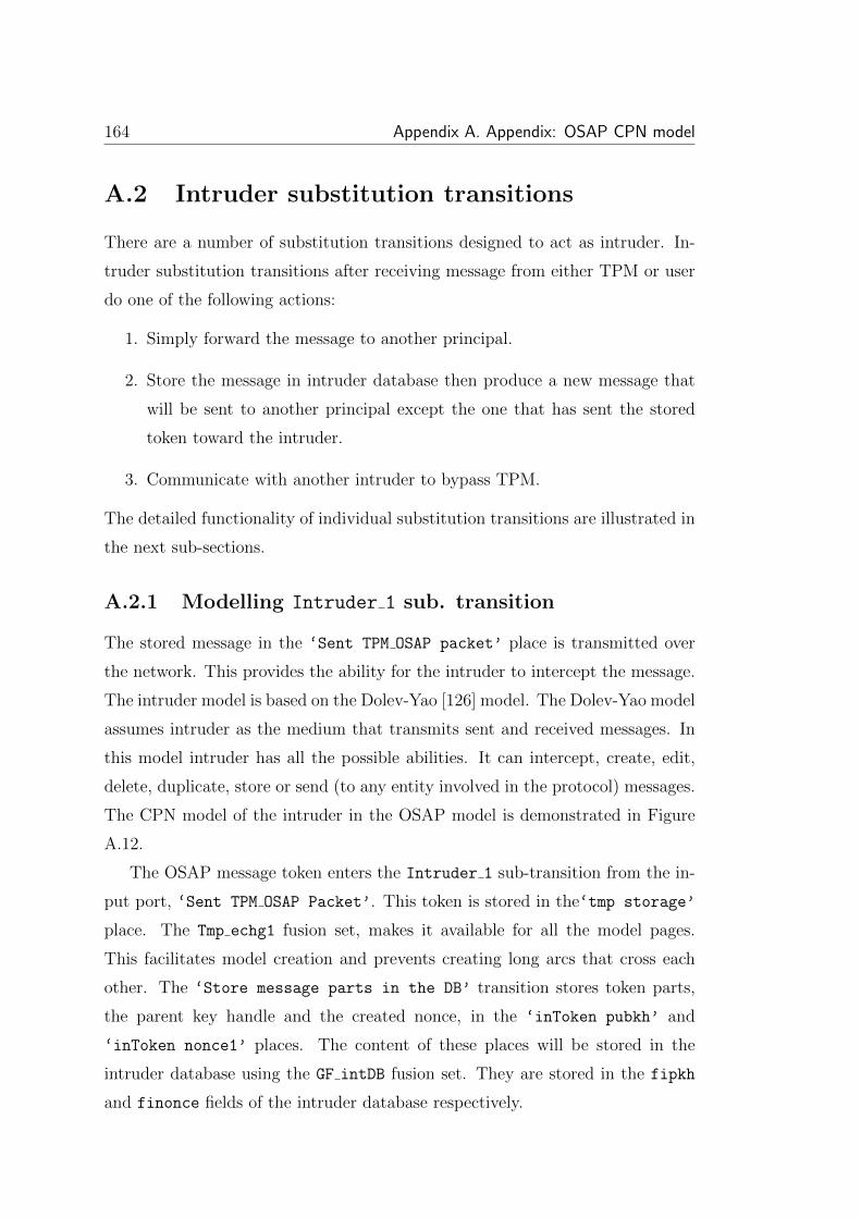
164 Appendix A. Appendix: OSAP CPN model
A.2 Intruder substitution transitions
There are a number of substitution transitions designed to act as intruder. In-
truder substitution transitions after receiving message from either TPM or user
do one of the following actions:
1. Simply forward the message to another principal.
2. Store the message in intruder database then produce a new message that
will be sent to another principal except the one that has sent the stored
token toward the intruder.
3. Communicate with another intruder to bypass TPM.
The detailed functionality of individual substitution transitions are illustrated in
the next sub-sections.
A.2.1 Modelling Intruder 1 sub. transition
The stored message in the ‘Sent TPM OSAP packet’ place is transmitted over
the network. This provides the ability for the intruder to intercept the message.
The intruder model is based on the Dolev-Yao [126] model. The Dolev-Yao model
assumes intruder as the medium that transmits sent and received messages. In
this model intruder has all the possible abilities. It can intercept, create, edit,
delete, duplicate, store or send (to any entity involved in the protocol) messages.
The CPN model of the intruder in the OSAP model is demonstrated in Figure
A.12.
The OSAP message token enters the Intruder 1 sub-transition from the in-
put port, ‘Sent TPM OSAP Packet’. This token is stored in the‘tmp storage’
place. The Tmp echg1 fusion set, makes it available for all the model pages.
This facilitates model creation and prevents creating long arcs that cross each
other. The ‘Store message parts in the DB’ transition stores token parts,
the parent key handle and the created nonce, in the ‘inToken pubkh’ and
‘inToken nonce1’ places. The content of these places will be stored in the
intruder database using the GF intDB fusion set. They are stored in the fipkh
and finonce fields of the intruder database respectively.

A.2. Intruder substitution transitions 165
bypass1
bypass1
vseq
vseq
vseq
vseq
vseq
vseq
vseq
finonce(vno_osap)
tpm1
fakedxchg1(vosap_msg)vosap_msg
vosap_msg
(vpkh, vno_osap)
vosap_msg
vseq
e
e
e
e
vseq
vseq
fipkh(vpkh)
(vpkh,vno_osap)vosap_msg
vosap_msg
vosap_msg
vseq
vseq
finonce(vno_osap)
fipkh(vpkh)
fiosap_msg(vosap_msg)
fiosap_msg(vosap_msg)
Bypass all TPMtransitions
[vseq=int1]
Bypass one TPMtransition
[vseq=int1]
TPMincluded
[ not vexcl_tpms andalso vinc_int]
TPM excluded
[vexcl_tpms andalso vinc_int]
check attack
start fieldsstorage
Create newmessage
[vseq=int1]
Forward stored message
[vseq=int1]
Store Whole message
in DB
[vseq=int1]
Store message parts
in DB
[vseq=int1]
ST2_2
csSEQ
ST2
csSEQ
inTokennonce1
GF_intDB csINTDB
CSO
GF_seq csSEQ
Run intruder2
OutcsSEQ
tmp outputTPM_OSAPmessage
csOSAP_MSG
int1change
csATTACK
CSI
GF_seqcsSEQ
JO4
1`()
UNIT
JO3
1`()
UNIT
JO2
1`()
UNIT
JO1
1`()
UNIT
ST1
csSEQ
tmp storage
Tmp_echg1 csOSAP_MSG
Sent TPM_OSAP
Tmp_echg1 csOSAP_MSG
ST2_1
csSEQ
outTokennonceGF_intDB
csINTDB
outTokenpubkhGF_intDB
csINTDB
IntruderDB
GF_intDBcsINTDB
Whole token
GF_intDBcsINTDB
inTokenpubkh
GF_intDB csINTDB
Sent TPM_OSAP
PacketIncsOSAP_MSG
outputTPM_OSAPmessageOut
csOSAP_MSG
Out
GF_intDB
GF_intDB
GF_intDB
GF_intDB
Tmp_echg1
GF_seq
GF_intDB
Out
GF_seq
In
Tmp_echg1
GF_intDB
1
1
1
1
Figure A.12: The Intruder 1(page Int 1) CPN model
The arc that connects ‘Store message parts in DB’ transition to the ‘tmp
storage’ place is a double arc that after a token is consumed by the transition
returns it again to the place. In some cases (that all the other required tokens
to fir the transition are provided) this makes a transition permanently enabled.
To prevent this the ‘JO 1’ enabler place, with just one token, is connected to
the transitions. This mechanism, enabling just once, allows a transition to only
be enabled once.
The transitions located in the intruder’s page can be enabled if the sequence
token value is int1. To enforce this condition all the transitions have the guard
[vseq=int1]. This sequencer token, moves from the first transition of the page
to the last one.
The transition ‘Store Whole message in DB’ after ‘Store message parts
in DB’ transition is enabled then stores the whole message in the intruder
database. The ‘JO 2’ and ‘Sent TPM OSAP’ places connected to this transi-
tion act the same as the illustrated ‘JO 1’ and ‘tmp storage’ places.
Intruder, after storing the message parts and the whole message checks whether
according to the model configuration TPM is excluded from the model or is in-
cluded in it. If TPM is excluded then ‘TPM excluded’ will be enabled. There-

166 Appendix A. Appendix: OSAP CPN model
fore, intruder does not perform any action and only bypasses the TPM. Intruder
then sends sequence token to Intruder 2 to enable it. Otherwise, TPM is in-
cluded in the model thus intruder tries to send a message toward that. The sent
message is produced by performing one of the following actions.
These actions are forwarding one of the stored messages to the TPM, creating
new messages and sending them to the TPM or bypassing the TPM completely.
One of the ‘Forward stored message’, ‘Create new message’ or ‘Bypass
one TPM transition’ transitions will be run randomly to do one of mentioned
actions.
The result of forwarding a message or creating a message will be stored in the
‘tmp output TPM OSAP message’ place. The ‘check attack’ transition will
check whether the new message is completely faked by the intruder or not. If
the attack has occurred, a posattack token will be stored in the ‘int1 change’
place, otherwise a token with negattack value will be added to the place. Func-
tion fakedxchg1 in Figure A.13 checks whether the content of the sent token is
fully based on the intruder’s knowledge or not. If ‘yes’ then it means the token
is faked. If ‘no’ it means the token is genuine.
fun fakedxchg1 (vosap_msg: csOSAP_MSG):csATTACK =
case vosap_msg of
(pkh_pub, no_osap) => negattack
| _ => posattack;
Figure A.13: The function fakedxchg1() details.
After verification, the result output token will be sent to the place ‘output
TPM OSAP message’. Then using the output port token will be forwarded to the
TPM. The current sequence of the model will change to the tpm1 by storing
tpm2 token in the CSO place.
The ‘Bypass one TPM transition’ is enabled when intruder decides to
send no message to the TPM. In this case the current sequence of the model,
bypass1, is put in the ‘Run intruder 2’ place. In CPN/Tools version 3.0.2 it is
not possible to connect a port directly to a fusion set. Thus a few transitions and
places are inserted between Intruder 1 and Intruder 2 transitions to connect

A.2. Intruder substitution transitions 167
them to each other in main model page.
A.2.2 Modelling Intruder 2 sub. transition
The Int 2 page (Figure A.15) can be enabled in two different situations: first
when TPM answer to the sent TPM OSAP enters the page, second when TPM is
bypassed by Intruder 1.
In the first case, TPM response to TPM OSAP is stored in ‘Sent TPM OSAP
Response’. The message and its parts are stored in intruder database by ‘Store
Whole message in DB’ and ‘Store message parts in DB’ transitions. Then
sequence token reaches to ST3. Intruder can randomly select either to forward
one of the stored messages in its database to the user by enabling ‘forward
stored message’ or to create a new message by enabling ‘Start create new
message’. In the former case the fetched message after storing in ‘Tmp Received
TPM OSAP Response’ is checked by ‘check attack’ transition and fakedxchg2()
(Figure A.14). Then it is sent toward user from ‘Received TPM OSAP Response’
output port. The fakedxchg2() function operation is similar to fakedxchg1().
In the latter case, intruder starts creating a new message. To prevent concurrent
access to finonce database field, vne opsap and vne are sequentially retrieved
by ‘fetch vne osap’ and ‘fetch vne’ transitions.vne, vne osap and fetched
vah are used by ‘create new message’ transition to compose the new message.
The next applied processes to created message to be sent outside the page are
similar to forwarded messages.
In the second case, when Intruder 1 has passed the sequence token to
Intruder 2, ‘TPM is bypassed’ transition is enabled. When sequence token
reaches to ST2 place, according to the model configuration, either ‘TPM is
included’ or ‘TPM is excluded’ transition is enabled. Excluding TPM from
the model prevents storing messages sent by TPM in intruder database. Thus
intruder cannot forward any6 messages. The only possible intruder action is
creating new message and sending it toward user. The intruder actions in a
configuration that TPM is included in the model are forwarding or creating new
message that will be followed by enabling either ‘Forward stored message’ or
‘Create new message’.

168 Appendix A. Appendix: OSAP CPN model
fun fakedxchg2 (vosap_res:csOSAP_RESPONSE): csATTACK =
case vosap_res of
(ah, ne, ne_osap) => negattack
| _ => posattack;
Figure A.14: The function fakedxchg2() details
A.2.3 Modelling Intruder 3 sub. transition
The Intruder 3 functionality, Figure A.16, is similar to Intruder 1. The in-
truder at first, stores the complete message,
TPM CreateWrapKey(ah, pkh, no, ..., SHA1(S, ne)⊕newauth), hmacS(ne, no, ...)
in its database. Then the intruder starts storing message parts recursively. The
TPM CreateWrapKey(ah, pkh, no, ..., SHA1(S, ne)⊕ newauth)
and hmacS(ne, no, ...) are processed separately. Extracting the hmacS(ne, no, ...)
parts (S, ne and no) is impossible thus the whole message is stored in fihmac output
database field of database. The shared secret is created based on public data,
therefore in this research it is assumed that intruder is able to store shared secret
in fiss field.
The complete TPM CreateWrapKey(ah, pkh, no, ..., SHA1(S, ne)⊕newauth)
message is stored in fiwrapkey input field of intruder’s database. The ah, pkh
and no will be stored in fiah, fipkh and finonce fields of the database respec-
tively.
The end of storing messages is the start of producing new messages to send
them to the TPM. When the sequence token reaches to ST6, if TPM is included
in model configuration then intruder performs its normal actions (including for-
warding a stored message, creating new message or bypassing TPM) otherwise
the only possible action is TPM bypass. Forwarding a message is performed by
fetching it from fiwrapkey msg field. TPM is bypassed when ‘Bypass TPM’ is
enabled. Finally, a message is created when ‘Int create new exchange 3’ is

A.2. Intruder substitution transitions 169
fiah(ah)
vseq
vseq
vseq
vseq
vseq
vseq
vseq
vseq
vseq
vne_osap
vne
vseq
vne
finonce(vne)
vseq vseq
vne_osap
finonce(vne_osap)
vseq
finonce(vne_osap)
finonce(vne)
vseq
vosap_res
vosap_res
vosap_res
user2e
e
e
e
vseq
vseq
vseq
vseq
(vah, vne, vne_osap)
vosap_res
vosap_res
fiah(vah)
fiosap_res(vosap_res)
fiah(vah)
put intruderah in DB
TPM isincluded
[not vexcl_tpms]
TPM isExcluded
[vexcl_tpms]
Start fetchingnonce
[vseq=int2]
fetch vne
[vseq=int2]
fetch vne_osap
[vseq=int2]
TPM isBypassed
[vseq=int2]
check attack
Forward stored message
[vseq=int2]
Create newmessage
[vseq=int2]
Store Whole message
in DB
[vseq=int2]
Store message parts
in DB
[vseq=int2]
intruderah
GF_intDB csINTDB
ST2_2
csSEQ
ST2
csSEQ
csSEQ
ST3_3
csSEQ
tmpvne
csNONCE
tmpvne_osap
csNONCE
outTokenne
GF_intDB csINTDB
outTokenne_osap
GF_intDB csINTDB
ST3_2
csSEQ
ST3_1
csSEQ
inTokenne_osap
GF_intDB csINTDB
inTokenne
GF_intDB csINTDB
csSEQ
int2change
csATTACK
Tmp Received TPM_OSAP Response
csOSAP_RESPONSE
csSEQ
CSOGF_seq csSEQ
JO1
1`()
UNIT
JO2
1`()
UNIT
1`()
UNIT
1`()
ST3
csSEQ
ST1
csSEQ
TPM_OSAP Response
Tmp_xch2csOSAP_RESPONSE
csOSAP_RESPONSE
outTokenah
GF_intDB csINTDB
csINTDB
Wholetoken
GF_intDBcsINTDB
inTokenah
GF_intDB csINTDB
csOSAP_RESPONSE
csOSAP_RESPONSE
GF_intDB
GF_intDB
GF_intDB
Tmp_xch2
GF_seq
GF_intDB
GF_intDB
GF_intDBGF_intDB
GF_intDB
vseq
user2
JO3
vseq
Start create newmessage(vah, vne, vne_osap)
Received TPM_OSAP ResponseOutOut
fakedxchg2 (vosap_res)
Int_2 page
IntruderDB
GF_intDBGF_intDB
fiosap_res(vosap_res)
CSIGF_seqGF_seq
vseq
BypassToken
InIn
Sent TPM_OSAP ResponseInIn
start fieldsstoragevosap_res
tmp storage
Tmp_xch2Tmp_xch2
ST2_1vseq
UNIT
JO4
Figure A.15: The Intruder 2 (page Int 2) CPN model
enabled. The CPN model of this transition is designed in Int 3 1 page and is
shown in Figure A.17.
Page Int 3 1 at first creates SHA1(S, ne)⊕newauth) part of faked message
by Create XOR WrapKey transition. The required inputs are fetched from the in-
truder fiss, finonce and fiauthdata database fields. The result will be used to
produce TPM CreateWrapKey(ah, pkh, no, ..., SHA1(S, ne) ⊕ newauth) part.
The ah, pkh and no are fetched from the fiah, fipkh and finonce fields.
The result is temporarily stored in WrapKey SHA place till ‘Generate HMAC S 1’
computes hmacS(ne, no, ...) by fetching required parameters sequentially from
finonce and fiss database fields then stores the result in hmac S 1 place. The
send transition combines tokens of both WrapKey SHA and hmac S 1 places to
produce the following final message,

170 Appendix A. Appendix: OSAP CPN model
TPM CreateWrapKey(ah, pkh, no, ..., SHA1(S, ne)⊕newauth), hmacS(ne, no, ...)
This message is stored in ‘TPM CreateWrapKey’ place and finally will be sent
to the Int 3 page using the TPM CreateWrapKey output port. Storing tpm4 token
in CSO place will change the global state of model. The ‘End create Exchg’
place by receiving the tpm4 token from end transition finishes the Int 3 1 page
and returns to the Int3 page.
The produced tokens by either ‘Forward stored message’ or ‘Int create
new exchange 3’ are stored in ‘tmp TPM CreateWrapKey Received Packet’
place. The ‘check attack’ transition by calling fakedxchg3(vwrapkey msg),
Figure A.18, ML-function investigates whether the third message sequence of pro-
tocol is faked or not. If the packet is faked a ‘posattack’ token will be put in the
‘int3 change’ place. The produced packet is stored in ‘TPM CreateWrapKey
Received Packet’ then will be sent to the ‘TPM CreateWrapKey Received Packet’
place in the Session 1 page using the output port. This packet is processed by
‘Process TPM CreateWrapKey message’ that its model is shown in T4 page.
A.2.4 Modelling Intruder 4 sub. transition
The Int 4 page (Figure A.19) functionality is similar to Int 2. The n′e and
keyblob parts of the input message at first are stored in fikeyblob and finonce
fields of the intruder’s database by ‘Store message parts in DB’ transition.
In the next step the transition ‘Store whole hmac’ stores the hmacS(n′e, no, ...)
part of the input in fihmac output field. The ‘Store Whole message in DB’
transition is enabled then (keyblob, n′e, hmacS(n′
e, no, ...)) is stored in the intruder
database fiwrapkey rsp field.
The sequence token after storing input message and its parts reaches to
the ST5 place. At this stage intruder can either enables ‘Forward stored
token’ to fetch a message from fiwrapkey rsp field then forwards it toward
user by storing it in ‘TPM CreateWrapkey Response’ or it can enable ‘Start
to create new message’ to start composing a message. To compose a new mes-
sage, shared secret (S ) and hmacS(n′e, no, ...) are produced by ‘Create shared

A.2. Intruder substitution transitions 171
secret intruder’ and ‘Generate output HMAC’ transitions. Then they are
composed by ‘Create new exchange’ to create the new message and storing it
in ‘TPM CreateWrapkey Response’ place. The stored response message will be
checked by fakedxchg4() ML-function (Figure A.20) then is sent to the user.
The Int 4 page can be enabled by entering sequence token from ‘Bypass
Token’ input port. In this case Intruder 3 has bypassed the TPM. After by-
passing TPM by Intruder 3 if the model applied configuration includes all the
TPMs then sequence token is passed to ST5 and the model operation will be sim-
ilar to when page is enabled by enteringTPM CreateWrapKey response message in
‘TPM CreateWrapKey Sent Response’ input port. Otherwise, TPM is excluded
from the current model configuration, therefore forwarding a complete response
by fetching it from intruder database is impossible. The only feasible action for
intruder is creating a new message thus ‘all TPM processes are Excluded’
transition is enabled then intruder starts creating a new message following the
previously illustrated steps.

172 Appendix A. Appendix: OSAP CPN modelIn
t_3 p
age
vseq
vseq
vseq
vseq
vseq
vseq vseq
vseq
vseq
vseq
finonce(v
no)
bypass2
tpm
4vseq
vseq
e
e
e
e
e
fihm
ac_outp
ut(
vhm
ac_outp
ut)
vseq
vseq
vseq
vseq
vseq
vseq
vseq
vseq
vseq
vseq
vseq
(vw
rapkey_in
put
, vhm
ac_outp
ut)
vw
rapkey_m
sg
vw
rapkey_m
sg
vw
rapkey_m
sg
intx
3
fixor_
outp
ut(
vxor_
outp
ut)
vxor_
outp
ut
(vss,v
ne,v
auth
data
)
vxor_
outp
ut
fipkh(v
pkh)
fiah(v
ah)
(vah,
vpkh,
vno,
vxor_
outp
ut)
fiss(v
ss)
(vss,
vne,
vno)
vw
rapkey_in
put
vhm
ac_outp
ut
fiw
rapkey_in
put(
vw
rapkey_in
put)
fiw
rapkey_m
sg(v
wra
pkey_m
sg)
fiw
rapkey_m
sg(v
wra
pkey_m
sg)
TPM
inclu
ded
[ not
vexcl_
tpm
s
andals
o
vin
c_in
t]
[vexcl_
tpm
s
andals
o
vin
c_in
t]
Bypass T
PM
[vseq=
int3
]
End
Int3
Sta
rt f
ield
sto
rage
Int
cre
ate
new
exchange 3
Int_
3_1
sto
re W
hole
XO
R
[vseq=
int3
]
extr
act
XO
Rfield
s
[vseq=
int3
]
sto
re f
ield
s o
fw
rapkey_in
put
[vseq=
int3
]
sto
re f
ield
shm
ac
[vseq=
int3
]
Forw
ard
sto
red
message
[vseq=
int3
]
Sto
rew
hole
message
[vseq=
int3
]
Sto
re m
essage
part
s in D
B
[vseq=
int3
]
ST6_3
csSEQ
csSEQ
ST6
csSEQ
inToken
no2
GF_in
tDB
csIN
TD
B
Run intr
uder
4O
ut
csSEQ
tmp T
PM
_Cre
ate
Wra
pKey
Receiv
ed P
acket
csW
RAPKEY_M
SG
csATTACK
CSO
GF_seq
csSEQ
End
Intr
uder
3
csSEQ
CSI
GF_seq
csSEQ
JO 5
1`()
UN
IT
JO 4
1`()
UN
IT
JO 1
1`()
UN
IT
JO 2
1`()
UN
IT
JO 3
1`()
UN
IT
Whole
hm
ac
GF_in
tDB
csIN
TD
B
ST5
csSEQ
ST4
csSEQ
ST3
csSEQ
ST2
csSEQ
ST1
csSEQ
TM
P S
tora
ge2
tmp_xchg3
csW
RAPKEY_M
SG
TM
P S
tora
ge1
tmp_xchg3
csW
RAPKEY_M
SG
ST6_1
Whole
XO
R t
oken
GF_in
tDB
csIN
TD
B
Share
d
Secre
t
GF_in
tDB
csIN
TD
B
all f
ield
sw
rapkey_in
put csW
RAPKEY_IN
PU
T
all f
ield
shm
ac
csH
MAC_O
UTPU
T
Whole
Wra
pkey_in
put
GF_in
tDB
csIN
TD
B
Intr
uder
DB
GF_in
tDB
csIN
TD
B
Whole
exchange 3
GF_in
tDB
csIN
TD
B
inToken
xor
csXO
R_O
UTPU
T
inToken
pkh
GF_in
tDB
csIN
TD
B
inToken
ah
GF_in
tDB
csIN
TD
B
TPM
_Cre
ate
Wra
pKey
Sent
Packet
IncsW
RAPKEY_M
SG
csW
RAPKEY_M
SG
In
GF_in
tDB
GF_in
tDB
tmp_xchg3
GF_seq
Out
GF_in
tDB
GF_in
tDB
GF_in
tDB
GF_in
tDB
GF_in
tDB
tmp_xchg3
GF_in
tDB
GF_seq
GF_in
tDB
Int_
3_1
vw
rapkey_m
sg
int3
change
fakedxchg3(v
wra
pkey_m
sg)
ST6_2
TPM
exclu
ded
Com
pute
new
auth
vw
rapkey_m
sg
vseq
vseq
vw
rapkey_m
sg
csSEQ
t2
check a
ttack
TPM
_Cre
ate
Wra
pKey
Receiv
ed P
acket
Out
Out
vw
rapkey_m
sg
Figure A.16: The Intruder 3 (page Int 3) CPN model

A.2. Intruder substitution transitions 173
()
() () () () () ()
vnevno
finonce(vne) finonce(vno)
vno
vne
tpm4
e
e
e
tpm4
vwrapkey_msg
vwrapkey_msg
(vwrapkey_input, vhmac_output)
vhmac_output
vwrapkey_input
(vss, vne, vno)
fiss(vss)
vxor_output
(vah,vpkh,vno,vxor_output)
()
finonce(vno)fiah(vah)fipkh(vpkh)
vseq
vseq
(vss, vne, vnewauth)
vseq
fiss(vss)finonce(vne)
fiauthdata(vnewauth)
Start ComputeHash
fetch ne_osap_user
fetch no_user
end
SendGenerateHMAC_S_1
Prepare TPM_CreateWrapKey
do XOR
[vseq=intx3]
Create_XOR_WrapKey
[vseq=intx3]
ST3
UNIT
ST2
UNIT
ST1
UNIT
tmpno_user
csNONCEtmp
ne_osap_usercsNONCE
CSOGF_seq
csSEQ
JO3
1`()
UNIT
JO2
1`()
UNIT
JO1
1`()
UNIT
End createExchg
OutcsSEQ
TPM_CreateWrapKey
OutcsWRAPKEY_MSG
TPM_CreateWrapKeyPacket
csWRAPKEY_MSG
hmac_S_1
csHMAC_OUTPUT
SHARED SECRETintruder
GF_intDB csINTDB
ne_osap_userint
GF_intDBcsINTDB
no_userint 2
GF_intDBcsINTDB
WrapKey_SHA
csWRAPKEY_INPUT
ComputeHash
UNIT
no_userint
GF_intDBcsINTDB
ah_userint
GF_intDB csINTDB
pkh_userint
GF_intDBcsINTDB
xor_output
csXOR_OUTPUT
Start XOR
csSEQ
SHARED SECRETIntruder 1
GF_intDB csINTDB
ne_userint
GF_intDB csINTDB
new_authint
GF_intDB csINTDB
Start Creatingnew exchg
IncsSEQ
In GF_intDBGF_intDBGF_intDB
GF_intDBGF_intDB GF_intDB
GF_intDBGF_intDB
GF_intDB
Out
Out GF_seq
Int_3_1 page
Figure A.17: The Int 3 1 page CPN model
fun fakedxchg3 (vwrapkey_msg:csWRAPKEY_MSG) : csATTACK =
case vwrapkey_msg of
((ah,pkh_pub,no,((ad_pkh_pub,ne_osap,no_osap),
ne,newauth_user)),((ad_pkh_pub,ne_osap,no_osap),ne,no))=>negattack
| _ => posattack;
Figure A.18: The ML-Function of fakedxchg3(...)

174 Appendix A. Appendix: OSAP CPN modelIn
t_4 p
age
vseq
vseq
vseq
vseq
vne_osap
vseq
vseq
vseq
vseq
vseq
vseq
vno_osap
vne_osap
finonce(v
ne_osap)
finonce(v
no_osap)
vseq
fiauth
data
(vnew
auth
)
vseq
vseq
vseq
vseq
vseq
vseq
vseq
vseq
vseq
vseq
vseq
vseq
vseq
finonce(v
no)
finonce(v
ne1)
vno
vne1
vw
rapkey_rs
p
(vkeyblo
b,
vne1,
vhm
ac_outp
ut)
vw
rapkey_rs
pvw
rapkey_rs
p
finonce(v
ne1)
e
vseq
fihm
ac_outp
ut(
vss,v
ne1,v
no)
fiss(v
ss)
vhm
ac_outp
ut
vseq
vseq
vseq
vseq
vseq
e (vss,v
ne1,v
no)
fihm
ac_outp
ut(
vhm
ac_outp
ut)
vseq
fakedxchg4(v
wra
pkey_rs
p)
vw
rapkey_rs
pvw
rapkey_rs
p
(vkeyblo
b,
vne,
vhm
ac_outp
ut)
vw
rapkey_rs
p
user5
vseq
e
e
e
e
vseq
vseq
vseq
finonce(v
ne)
fikeyblo
b(v
keyblo
b)
fiw
rapkey_rs
p(v
wra
pkey_rs
p)
fiw
rapkey_rs
p(v
wra
pkey_rs
p)
vhm
ac_outp
ut
fikeyblo
b(v
keyblo
b)
Com
pute
new
auth
[vseq=
int4
]
Sta
rt t
oCre
ate
Keyblo
b
[vseq=
int4
]
[vseq=
int4
]
fetc
h
vno_osap
[vseq=
int4
]
Cre
ate
Share
dSecre
t in
truder
[vseq=
int4
]
Cre
ate
Keyblo
b
[vseq=
int4
]
t2t1
all T
PM
pro
cesses
are
Exclu
ded
[vexcl_
tpm
s]
all T
PM
s
are
inclu
ded
[not
vexcl_
tpm
s]
[vseq=
int4
]
fetc
h
hm
ac n
e1
[vseq=
int4
]
Sta
rt t
o c
reate
new
message
[vseq=
int4
]
sta
rt f
ield
ssto
rage
Genera
te
outp
ut
HM
AC
[vseq=
int4
]
Sto
re h
mac
part
s in D
B
[vseq=
int4
]Sto
rew
hole
hm
ac
[vseq=
int4
]
TPM
is
Bypassed
[vseq=
int4
]
check a
ttack
Cre
ate
new
exchange
[vseq=
int4
]
Forw
ard
sto
red
token
[vseq=
int4
]
Sto
re W
hole
message
in D
B
[vseq=
int4
]
Sto
rem
essage p
art
s in D
B
[vseq=
int4
]
ST8
csSEQ
ST7
csSEQ
ST6_3
csSEQ
ST6_2
csSEQ
ST6_1 csSEQ
tmp
ne_osap csN
ON
CE
tmp
no_osap csN
ON
CE
intr
uder
keyblo
b
GF_in
tDB
csIN
TD
B
ST6
csSEQ
ad_pkh
GF_in
tDB
csIN
TD
B
csIN
TD
BcsIN
TD
B
new
auth
GF_in
tDB
csIN
TD
B
share
d s
ecre
tTPM
2 csSH
ARED
_SECRET
ST4_2
csSEQ
ST4_1
csSEQ
ST4
csSEQ
csIN
TD
B
outT
oken
hm
ac n
e1
GF_in
tDB
csIN
TD
B
csN
ON
CE
csSEQ
ST5_2
csSEQ
csSEQ
tmpTPM
_Cre
ate
Wra
pKey
Response
tmp_xchg4
csW
RAPKEY_RESPO
NSE
tmp
sto
rage
tmp_xchg4
csW
RAPKEY_RESPO
NSE
inToken
ne2
GF_in
tDB
csIN
TD
B
JO 5
1`()
UN
IT
ST9
csSEQ
outT
oken
hm
ac S
S
GF_in
tDB
csIN
TD
B
ST2
csSEQ
ST1
csSEQ
JO 6
1`()
UN
IT
inToken
hm
ac
GF_in
tDB
csIN
TD
B
inToken
hm
ac2
tmp_sto
rage
csH
MAC_O
UTPU
T
Bypass
Token
IncsSEQ
int4
change
csATTACK
TPM
_Cre
ate
Wra
pKey
Response
csW
RAPKEY_RESPO
NSE
CSI
GF_seq
csSEQ
CSO
GF_seq
csSEQ
JO 4
1`()
UN
IT
JO 3
1`()
UN
IT
JO 2
1`()
UN
IT
JO 1
1`()
UN
IT
ST5
csSEQ
ST3
csSEQ
csIN
TD
B
outT
oken
keyblo
b
GF_in
tDB
csIN
TD
B
Intr
uder
DB
GF_in
tDB
csIN
TD
B
Whole
Token
GF_in
tDB
csIN
TD
B
inToken
hm
ac1
tmp_sto
rage
csH
MAC_O
UTPU
T
inToken
keyblo
bG
F_in
tDB
csIN
TD
B
TPM
_Cre
ate
Wra
pKey
final Response
Out
csW
RAPKEY_RESPO
NSE
TPM
_Cre
ate
Wra
pKey
Sent
Response
IncsW
RAPKEY_RESPO
NSE
GF_in
tDB
GF_in
tDB
GF_in
tDB
GF_seq
tmp_xchg4
GF_in
tDB
GF_in
tDB
Intm
p_xchg4
In
tmp_sto
rage
GF_in
tDB
GF_in
tDB
tmp_sto
rage
GF_seq
Out
GF_in
tDB
GF_in
tDB
GF_in
tDB
GF_in
tDB
vss
vseq
fetc
h
vne_osap
ne_osap
GF_in
tDB
GF_in
tDB
no_osap
GF_in
tDB
GF_in
tDB
fiauth
data
(new
auth
)
vseq
fikeyblo
b(v
ss,v
new
auth
)
user5
fihm
ac_outp
ut(
vhm
ac_outp
ut)outT
oken
hm
ac
GF_in
tDB
GF_in
tDB
csIN
TD
B
vseq
tmp
hm
ac n
o
fetc
h
hm
ac n
oST5_3
outT
oken
hm
ac n
oG
F_in
tDB
GF_in
tDB
vseq
tmp
hm
ac n
e1
vne1
vno
ST5_1
csN
ON
CE
outT
oken
ne
GF_in
tDB
GF_in
tDB
(vauth
data
,vne_osap,
vno_osap)
fiauth
data
(vauth
data
)vno_osap
vseq
Figure A.19: The Intruder 4 (page Int 4) CPN model
fun fakedxchg4 (vwrapkey_rsp:csWRAPKEY_RESPONSE) : csATTACK =
case vwrapkey_rsp of
(((ad_pkh_pub,ne_osap,no_osap),newauth_user),
ne1,((ad_pkh_pub,ne_osap,no_osap),ne1,no))=> negattack
| _ => posattack;
Figure A.20: The ML-Function of fakedxchg4(...)

A.3. TPM substitution transitions in OSAP 175
A.3 TPM substitution transitions in OSAP
The first TPM substitution transition, ‘Process TPM OSAP’, (page T1) extracts
TPM OSAP command parameters then sends back its response to the user by ‘send
TPM OSAP Response’ substitution transition(page T2). The session shared se-
cret for TPM usage is created by ‘Create Shared Secret TPM’ (page T3).
The third protocol message, OSAP Msg#3, is treated by ‘Process TPM Create
WrapKey message’(page T4) Its response is produced by ‘Send TPM CreateWrapKey
Response’ and is sent to the user. These substitution transitions are illustrated
with more detail in next sub-sections.
A.3.1 Modelling ‘Process TPM OSAP’ sub. transition
The transition ‘Process TPM OSAP’ (A.21) after receiving the TPM OSAP com-
mand message in ‘Received TPM OSAP Message’ stores its parts in ‘pkh from
user’ and no osap tpm places. Then ‘Compare pkhs’ transition compares the
TPM pkh (pkh tpm) and received pkh together. If they were equal then next
TPM substitution transition (T2) will be enabled otherwise session will be ter-
minated.

176 Appendix A. Appendix: OSAP CPN model
e
vseq
(vpkh,vno_osap)
vno_osap
Compare pkh's
[vseq=tpm1]
CSOGF_seq
csSEQ
1`pkh_pub
csPUBKH
csSEQ
csPUBKH
no_osap_tpm
no_osap_tpm csNONCE
csOSAP_MSG
UNIT
no_osap_tpm
GF_seq
CSI
GF_seqGF_seq
Received TPM_OSAP Message
InIn
vpkh
pkh_tpm
pkh_tpmpkh_tpm
PROCESSTPM_OSAP
Message
vpkhvpkhu
if vpkhu=vpkh then 1`tpm2else 1`terminateses
End processingTPM_OSAP msg
OutOut
T1 page
pkh from user
Figure A.21: The ‘Process TPM OSAP’ (page T1) substitution transition
A.3.2 Modelling ‘Send TPM OSAP Response’ sub. transi-
tion
TPM after processing TPM OSAP message prepares the response using ‘Send
TPM OSAP Response’ substitution transition (page T2, Figure A.22). The re-
quired tokens to create the response are provided by ne osap tpm, ne tpm and
ah tpm places. The result will be stored in the ‘TPM OSAP Response’ place.
The CSI and CSO places are used to change the current sequence of the model in
the GF seq fusion set. The ‘Create Shared Secret’ place transfers sequence
to ‘Create Shared Secret TPM’ substitution transition (in main page of the
CPN model) after triggering ‘SEND TPM OSAP RESPONSE’.

A.3. TPM substitution transitions in OSAP 177
T2 page
tpm3vseq
e
()
vahvnevne_osap
SEND TPM_OSAP RESPONSE
[vseq=tpm2]
CSIGF_seq
csSEQ
CSOGF_seq
csSEQ
ah_tpm
1`ah
csAUTH_HANDLE
ne_tpm
ne_tpm
1`ne
csNONCE
ne_osap_tpm
ne_osap_tpmcsNONCE
Start Seq2
InUNIT
Create Shared Secret
OutUNIT
TPM_OSAP Response
OutcsOSAP_RESPONSE
Out
Out
In
ne_osap_tpm ne_tpm
GF_seqGF_seq
1`ne_osap
(vah, vne,vne_osap)
Figure A.22: The ‘Send TPM OSAP Response’(page T2) substitution transition
A.3.3 Modelling ‘Create Shared Secret TPM’ sub. transi-
tion
The ‘Create Shared Secret TPM’ substitution transition in main page of the
CPN model, Figure A.23, produces the TPM shared secret. To generate the
shared secret required token are fetched from ne osap tpm, no osap tpm and
‘authdata pkh tpm’ places. The double arcs are used to return tokens after
‘GENERATE SHARED SECRET TPM transition is enabled. The result will be stored
in the shared secret TPM global fusion set.
vseq
vseq vseq
e
vno_osapvauthdata
[vinc_int]
GENERATE SHAREDSECRET TPM
[vseq=tpm3]
csSEQ
CSIGF_seq
csSEQ
UNIT
ne_osap_tpm
ne_osap_tpmcsNONCE
no_osap_tpm
no_osap_tpm
shared secret TPM
shared_secret_tpmcsSHARED_SECRET
authdata_pkhtpm
ad_pkh_tpm
1`ad_pkh_pub
csAUTH_DATA
UNIT
ad_pkh_tpm
shared_secret_tpm
no_osap_tpmne_osap_tpm
GF_seq
(vauthdata,vne_osap,vno_osap)
[not vinc_int]
vne_osap
CreateShared Secret
InIn
vseq
user2
e
if bypass intruder2
seq
CSOGF_seqGF_seq
int2
if run intruder2End
Creating SCOutOut
csSEQ
1`ne_osap
T3 page
csNONCE
Figure A.23: The ‘Create Shared Secret TPM’ (page T3) substitution transi-tion
When both ‘Create Shared Secret TPM’ and ‘Send TPM OSAP Response’
substitution transitions of page Session 1 are run the ‘Hash is Done’ transi-

178 Appendix A. Appendix: OSAP CPN model
tion in the model main page can be enabled. Then the response of the TPM
to the TPM OSAP message will be stored in the ‘Sent TPM OSAP Response1’
place in main page of the model. According to the model configuration when
intruders are included in the model, ‘if run intruder2’ will be enabled oth-
erwise ‘if bypass intruder2’ will be enabled to determine the next model
transition to be run.
A.3.4 Modelling ‘Process TPM CreateWrapKey message’
This substitution transition, Figure A.24, is the forth TPM processing page. It
processes the TPM CreateWrapKey(....) message and stores its input parame-
ters in designated places.
The ‘Retrieve no’ transition stores hmacS(ne, no, ...) in hmac S user place
and TPM CreateWrapKey(ah, pkh, no, ..., SHA1(S, ne)⊕newauth) in ‘tmp Wrapkey’
place. The no nonce, used by TPM to produce last message of protocol, is ex-
tracted by ‘extract no’ transition and will be stored in no TPM place. Af-
ter extracting message parts ‘Compute Hash’ will compute the hmac using
its knowledge. Then ‘Check integrity Hash’ compares computed and re-
ceived hmacs. The successful integrity check enables next TPM substitution
transition (T5). The TPM creates final message and sends it to the user by
‘Send TPM CreateWrapKey Response’ transition. Otherwise, the unsuccessful
integrity check will terminate the session.
A.3.5 Modelling ‘Send TPM CreateWrapKey Response’
In this page, Figure A.25, at first hmacS(n′e, no, ...) is generated by ‘Generate
HMAC S’ place. To generate it S from ‘shared secret TPM’, n′e from ne1 TPM 1
and no from no TPM fusion sets are fetched. The result is stored in ‘hmac s TPM’
place. The ‘Generate HMAC S’ transition is enabled when [vseq=tpm5] is eval-
uated to TRUE. Then ‘Create Keyblob’ is enabled to produce keyblob and
stores it in keyblob TPM place. The ‘Prepare Response of Wrapkey’ com-
poses keyblob, n′e, hmacS(n′
e, no, ...) using ne1 TPM 2, hmac s TPM and keyblob TPM
tokens. The result is stored in ‘TPM CreateWrapKey Response’. Depending on

A.3. TPM substitution transitions in OSAP 179
e
vne
vss
vno
vno
(vah, vpkh,vno, vxor_output)
vss
Compute Hash
extract no
Retrieve no
1`()
UNIT
csSEQ
hmac_S_user2
received_hmaccsHMAC_OUTPUT
ne_tpm
ne_tpm
1`ne
csNONCE
csHMAC_OUTPUT
csSHARED_SECRET
csSEQ
tmpWrapkey
hmac_S_user
received_hmaccsHMAC_OUTPUT
csSHARED_SECRET
no_TPM
no_tpm
UNIT
csWRAPKEY_MSG
no_tpm
received_hmac
ne_tpm
received_hmac
vwrapkey_input
csNONCE
CSIGF_seqGF_seq
vhmac_output
SSTPM
shared_secret_tpmshared_secret_tpm
JO4
CSOGF_seqGF_seq
()
vhmac_tpm
vseq
(vwrapkey_input, vhmac_output)
TPM_CreateWrapKeyMessage
InIn[vseq=tpm4]
T4 page
shared secretTPM
shared_secret_tpmshared_secret_tpm
csWRAPKEY_INPUT
vhmac_user
computed Hash
end
OutOut
Check integrityHash
if vhmac_tpm=vhmac_user then tpm5else terminateses
(vss,vne,vno)
Figure A.24: The ‘Process TPM CreateWrapKey message’ (page T4) CPNmodel
model configuration either Intruder 4 (when intruder is included in model) or U5
(when intruder is excluded from the model) substitution transition in Session 1
page will be enabled.

180 Appendix A. Appendix: OSAP CPN model
vseq
user5
vseq vseq
(vss,vnewauth)
vnewauth
e
vseq
()
vkeyblob
vss
vno
(vss,vne1,vno)
vhmac_output
[vinc_int] [not vinc_int]
Generate HMAC_S
[vseq=tpm5]
Prepare Response ofWrap Key
[vseq=tpm5]
csSEQ
start creatkeyblob
UNIT
csSHARED_SECRET
1`newauth
csAUTH_DATA
JO2
1`()
UNIT
1`()
UNITCSI
GF_seq csSEQ
ne1_TPM_2ne1_tpm
1`ne1
csNONCE
keyblob_TPM
csKEYBLOB
shared secretTPM
shared_secret_tpm
no_TPMno_tpm
csNONCE
hmac_s_TPM
csHMAC_OUTPUT
ne1_TPM_1
ne1_tpm
1`ne1
csNONCE
Start Seq4
InUNIT
csWRAPKEY_RESPONSE
In
ne1_tpmno_tpmshared_secret_tpm
ne1_tpm
vne1
csSHARED_SECRET
e
JO1
e
GF_seq
csSEQ
if run intruder4if bypass intruder4
int4
seq
CSOGF_seqGF_seq
SHARED SECRETTPM2
shared_secret_tpmshared_secret_tpm
vseq
vne1
TPM_CreateWrapKeyResponse
OutOut
(vkeyblob,vne1,vhmac_output)
vss
Create Keyblob
e
New_authDatatpm
new_auth_tpmnew_auth_tpm
T5 page
Figure A.25: The ‘Send TPM CreateWrapKey Response’ (page T5) CPN model

Appendix B
Appendix: SKAP CPN model
The required steps of modeling SKAP protocol and the main model pages are
illustrated in the Section 4.3. This appendix provides more detail about SKAP
model colour sets, variables and CPN pages. The list of all defined colour sets
and declared variables based on them is shown in Figure B.1 and B.2. The colour
sets 1 to 4 (in Figure B.1) are CPN/Tools standard colour sets. The user-defined
colour sets are illustrated as follows:
181

182 Appendix B. Appendix: SKAP CPN model
05 colset csSEQ = with user1 | user2 | user3 | user4 | user5 |
tpm1 | tpm2 | tpm3 | tpm4 | tpm5 | int1 | int2 | int3 |
int4 | intkeycrt | bypass1 | bypass2 | tpmkeycrt |
userkeycrt | jo | endses | termses | next ;
The csSEQ is the colour set defined to implement sequence token mechanism.
This colour set usage in guard inscrription of the page first transition prevents
concurrent runs of CPN pages. This mechanism details are provided in Section
4.1.3. To make a page active, it is necessary to assign corresponding value of
that page in csSEQ colour set to sequence token. For example, to make first
user page active, user1 value should be assigned to sequence token. To move
sequence token inside a page from one transition to the other, the next value
should be assigned to sequence token.
06 colset csCONFIG = with COMCH |
INTRUDER ;
This colour set is used to define which mode will be the CPN model active mode.
In communication channel mode COMCH will be assigned to corresponding config-
uration variable. In intruder mode, INTRUDER will be assigned to configuration
variable.
07 colset csTERMS = with null | response | s | sk_pkh_pri |
pk_pkh_pub | ne1 | newkey | nokey | ah | ne | ad_pkh_pub |
c1 | c2 | pkh | no | newauth | ahi | ni | si | newkeyi |
newauthi | pkhi | ad_pkh_pubi | pk_pkh_pubi ;
The csTERM colour set defines all the terms used in protocol modelling. The
chosen terms are defined exactly based on the structure of protocol messages.
For example, ah stands for authorisation handle. Intruder is added to the model
for analysis purposes and does not exist in the original protocol model. They are
suggested by designer. The used terms for intruder are differentiated with other
terms by adding i suffix. For example, ni is the created nonce by intruder.
08 colset csCONST = subset csTERMS with [c1, c2];

183
This colour set is used to define constants ‘1’ and ‘2’ that are used in the protocol.
09 colset csATTACK = with posattack | negattack;
The intruder after creating a message checks it to investigate whether it is a
faked message or not. For the faked messages a token with the posattack value
will be stored in corresponding place otherwise a negattack token is stored.
10 colset csARG = subset csTERMS with [null];
This colour set is designed to model used null parameters in SKAP Msg#3 and
SKAP Msg#4 Stages of protocol.
11 colset csSS = subset csTERMS with [s, si];
This colour set is a subset of csTERMS to store shared secret S
12 colset csERROR = with
correct_enc1 | incorrect_enc1 | correct_ah | incorrect_ah |
correct_pkh1 | incorrect_pkh1 | correct_pkh2 |
incorrect_pkh2 | correct_newauth | incorrect_newauth |
correct_hmac1 | incorrect_hmac1 | correct_hmac2 |
incorrect_hmac2 | correct_keyblob | incorrect_keyblob;
The csERROR colour set is used to implement error-discovery mechanism . Based
on different situations that error can occur different colours are designed. For
example, when in SKAP Msg#3, ah is sent from user to the TPM, the received
value by TPM is compared with the sent amount by TPM. If they were equal,
the result of comparison will be a token with correct ah value otherwise the
result will be a token with incorrect ah value.
13 colset csPKH = subset csTERMS with [pkh,pkhi];
The members of csPKH colour set are parent key handle(pkh) and faked parent
key handle by intruder(pkhi).

184 Appendix B. Appendix: SKAP CPN model
14 colset csKEY = subset csTERMS with [sk_pkh_pri, pk_pkh_pub,
pk_pkh_pubi, newkey, newkeyi, nokey];
The csKEY colour set defines all the used keys in the protocol modelling. Each
part of allocated name has its specific meaning. For example, sk pkh pri stands
for the secret key of parent key handle which is a private value. Intruder is
able to fake public keys so keys such as pk pkh pubi and newkeyi are defined.
15 colset csNONCE = subset csTERMS with [no, ne, ne1, ni];
The csNONCE colour set defines all the used nonces in protocol stages.
16 colset csTPMKEY = subset csKEY with [sk_pkh_pri,
pk_pkh_pub, nokey];
The stored keys in TPM are defined by csTPMKEY colour set.
17 colset csESS = product csSS * csTPMKEY;
The encrypted shared secret csESS colour set is designed to store Spk(pkh).
18 colset csAUTH_DATA = subset csTERMS with
[ad_pkh_pub, ad_pkh_pubi, newauth, newauthi];
This colour set is designed for storing authorisation data of parent key handle,
faked by intruder and new authorisation data.
19 colset csAH = subset csTERMS with [ah, ahi];
This colour set is used for tokens carrying authorisation handle.
20 colset csSKAP_MSG = product csPKH * csESS * csSEQ * csCONFIG;
This colour set is used for tokens and places carrying or storing TPM SKAP(pkh,
Spk(pkh) message. The last two fields csSEQ*csCONFIG are added for modelling
purposes. They carry sequence token and current configuration of model.
21 colset csSKAP_RES = product csAH * csNONCE * csSEQ * csCONFIG;

185
This colour set stores the TPM response ah, ne to the TPM SKAP(pkh, Spk(pkh))
request.
22 colset csSESSIONKEY = product csSS * csAUTH_DATA *
csNONCE * csCONST;
To store either K1 or K2 session secrets, the csSESSIONKEY colour set is used. It
is a product of S, ad(pkh), ne, and ‘1’ or ‘2’ colour sets.
23 colset csKEYBLOB = product csSESSIONKEY * csKEY;
Is the colour set of used keyblob in SKAP Msg#4.
24 colset csCRTWK=product csAH * csPKH * csNONCE;
Is the used colour set for modelling ah, pkh, no arguments of TPM CreateWrapKey
command.
25 colset csENCAUTH = product csSESSIONKEY * csAUTH_DATA;
Is used for modelling encK2(newauth) part of TPM CreateWrapKey command.
26 colset csHMAC = product csSESSIONKEY * csARG * csNONCE *
csNONCE;
Is used for modelling hmacK1(null, ne, no) part of SKAP Msg#3.
27 colset csCRTWK_MSG = product
csCRTWK * csENCAUTH * csHMAC * csSEQ * csCONFIG;
The complete message of SKAP Msg#3 is modelled b this colour set. It is product
of all the message parts (csCRTWK*csENCAUTH*csHMAC). The last two colour sets
(csSEQ and csCONFIG) are used for modelling purposes.
28 colset csCRTWK_RES = product
csKEYBLOB * csNONCE * csHMAC * csSEQ * csCONFIG;

186 Appendix B. Appendix: SKAP CPN model
This colour set is designed for modelling TPM response to the TPM CreateWrapKey
command. It is created as the product of csKEYBLOB, csNONCE and csHMAC mes-
sage parts. Like csCRTWK MSG colour set, the last two parts are used for modelling
purposes.
29 colset csINTDB = union
fiskap_msg : csSKAP_MSG + fipkh : csPKH +
fiess : csESS + ficrtwk_msg : csCRTWK_MSG +
fiencauth : csENCAUTH + fihmac : csHMAC +
fiskap_res : csSKAP_RES + fiah : csAH +
fino : csNONCE + fine : csNONCE +
ficrtwk_res : csCRTWK_RES +
fikeyblob : csKEYBLOB +
fine1 : csNONCE + fiss : csSS +
finewauth : csAUTH_DATA +
fiauthdata : csAUTH_DATA +
fikey : csKEY;
The csINTDB colour set is designed to create an intruder database that stores
all the messages passed through it. Intruder can store in the database complete
messages and their parts. For each message and its parts, required fields are
available in the database. Illustration of SKAP model CPN pages is provided in
next sub-sections.

187
01 colset UNIT = unit;
02 colset INT = int;
03 colset BOOL = bool;
04 colset STRING = string;
05 colset csSEQ = with user1 | user2 | user3 | user4 | user5 | tpm1 | tpm2 | tpm3 | tpm4 |
tpm5 | int1 | int2 | int3 | int4 | intkeycrt | bypass1 | bypass2 | tpmkeycrt |
userkeycrt | jo | endses | termses | next ;
06 colset csCONFIG = with COMCH |
INTRUDER ;
07 colset csTERMS = with null | response | s | sk_pkh_pri | pk_pkh_pub | ne1 | newkey |
nokey | ah | ne | ad_pkh_pub | c1 | c2 | pkh | no | newauth | ahi | ni | si |
newkeyi | newauthi | pkhi | ad_pkh_pubi | pk_pkh_pubi ;
08 colset csCONST = subset csTERMS with [c1, c2];
09 colset csATTACK = with posattack | negattack;
10 colset csARG = subset csTERMS with [null];
11 colset csSS = subset csTERMS with [s, si];
12 colset csERROR = with
correct_enc1 | incorrect_enc1 | correct_ah | incorrect_ah | correct_pkh1 |
incorrect_pkh1 | correct_pkh2 | incorrect_pkh2 | correct_newauth |
incorrect_newauth | correct_hmac1 | incorrect_hmac1 | correct_hmac2 |
incorrect_hmac2 | correct_keyblob | incorrect_keyblob;
13 colset csPKH = subset csTERMS with [pkh,pkhi];
14 colset csKEY = subset csTERMS with [sk_pkh_pri, pk_pkh_pub,
pk_pkh_pubi, newkey, newkeyi, nokey];
15 colset csNONCE = subset csTERMS with [no, ne, ne1, ni];
16 colset csTPMKEY = subset csKEY with [sk_pkh_pri, pk_pkh_pub, nokey];
17 colset csESS = product csSS * csTPMKEY;
18 colset csAUTH_DATA = subset csTERMS with
[ad_pkh_pub, ad_pkh_pubi, newauth, newauthi];
19 colset csAH = subset csTERMS with [ah, ahi];
20 colset csSKAP_MSG = product csPKH * csESS * csSEQ * csCONFIG;
21 colset csSKAP_RES = product csAH * csNONCE * csSEQ * csCONFIG;
22 colset csSESSIONKEY = product csSS * csAUTH_DATA*csNONCE*csCONST;
23 colset csKEYBLOB = product csSESSIONKEY * csKEY;
24 colset csCRTWK=product csAH * csPKH * csNONCE;
25 colset csENCAUTH = product csSESSIONKEY * csAUTH_DATA;
26 colset csHMAC = product csSESSIONKEY * csARG * csNONCE *csNONCE;
27 colset csCRTWK_MSG = product
csCRTWK * csENCAUTH * csHMAC * csSEQ * csCONFIG;
28 colset csCRTWK_RES = product
csKEYBLOB * csNONCE * csHMAC * csSEQ * csCONFIG;
29 colset csINTDB = union
fiskap_msg : csSKAP_MSG + fipkh : csPKH +
fiess : csESS + ficrtwk_msg : csCRTWK_MSG +
fiencauth : csENCAUTH + fihmac : csHMAC +
fiskap_res : csSKAP_RES + fiah : csAH +
fino : csNONCE + fine : csNONCE +
ficrtwk_res : csCRTWK_RES +
fikeyblob : csKEYBLOB +
fine1 : csNONCE + fiss : csSS +
finewauth : csAUTH_DATA +
fiauthdata : csAUTH_DATA +
fikey : csKEY;
Figure B.1: The list of SKAP CPN model colour sets

188 Appendix B. Appendix: SKAP CPN model
01 var vcfg : csCONFIG;
02 var vseq, vtmpseq, vjo:csSEQ;
03 var vpubkey,vskey:csTPMKEY;
04 var vskap_msg:csSKAP_MSG;
05 var verr : csERROR;
06 var vad_pkh, vnewauth,
07 vnewauthi:csAUTH_DATA;
08 var vpkh, vpkh1, vpkh2 : csPKH;
09 var vah, vah1, vah2:csAH;
10 var vne, vno, vne1:csNONCE;
11 var vss:csSS;
12 var vess:csESS;
13 var vskap_res:csSKAP_RES;
14 var vsesk1,vsesk2, vsesk:csSESSIONKEY;
15 var vconst1,vconst2:csCONST;
16 var vencauth:csENCAUTH;
17 var vnewkey : csKEY;
18 var vhmac, vhmac1,
19 vhmac2:csHMAC;
20 var vcrtwk:csCRTWK;
21 var vcrtwk_msg:csCRTWK_MSG;
22 var vcrtwk_res:csCRTWK_RES;
23 var vnull:csARG;
24 var vkeyblob : csKEYBLOB;
25 var vkey: csKEY;
26 val cCONFIG = INTRUDER;
27 val cNEXT_USER1 = int1;
28 val cNEXT_TPM2 = int2;
29 val cNEXT_USER3 = int3;
30 val cNEXT_TPM4 = int4;
Figure B.2: The list of SKAP model variables

B.1. Intruder substitution transitions in SKAP 189
B.1 Intruder substitution transitions in SKAP
There are a number of transitions designed for intruder to model its behaviour
The main intruder actions are retrieving data from received messages then storing
them in its database, forwarding received messages from TPM or user toward
user or TPM, creating new messages based on stored tokens in intruder database
and sending them toward TPM or user. The next sub-sections are illustrating
pages that implement mentioned roles.
The ‘Intruder 1’ functionality
The input token is stored in ‘TPM SKAP message1’ (Figure B.3) place by ‘Temporarily
Store TPM SKAP’ transition. This transition is enabled when [vseq=int1 andalso
vcfg=INTRUDER] is evaluated to TRUE (the sequence token value is int1 and
current configuration of model is INTRUDER). The arc inscription of transition,
(vpkh, vess, vseq, vcfg), demonstrates included fields of token. Variable
vpkh contains pkh part of message, vess keeps Spk(pkh), vseq holds sequence
token and vcfg is current system configuration.
The double arc between transition ‘Temporarily Store TPM SKAP’ and place
‘TPM SKAP message1’ makes the transition always enabled. To prevent that
JO1 place with initial value of “1`JO” is used. The number of tokens (only one)
in this place determines the number of times (just once) ‘Temporarily Store
TPM SKAP’ will be enabled. After temporary storage of input token, ‘store
SKAP msg message and its parts in DB’ transition stores whole the message
and its parts using the following arc inscription, in intruder database through
‘message and parts’ place as a member of INT DB fusion set.
“1`fiskap msg(vskap msg)
++1`fipkh(vpkh)
++1`fiess(vess)”
The next step after message storage is forwarding stored message, creating a
new message or bypassing TPM. The ‘forward stored TPM SKAP msg’ substi-
tution transition fetches one previously stored message from database and stores
it in ‘TPM SKAP message’ place. The ‘create new TPM SKAP msg’ substitu-

190 Appendix B. Appendix: SKAP CPN model
vjo
vskap_msg
(vpkh,vess, vseq, vcfg)
vskap_msg
vjo
(vpkh,vess, vseq, vcfg)
fakedxchg1(vskap_msg)bypass1
vseq
vskap_msg
(vpkh,vess, vseq, vcfg)
next
TemporarilyStore TPM_SKAP
[vseq = int1andalso vcfg = INTRUDER]
bypass TPM1
forward stored TPM_SKAP msg
I1_frd
create new TPM_SKAP msg
I1_crt
check attack
store skap_msgmessage and its
parts in DB
1`jo
csSEQ
JO1
1`jo
csSEQ
int1change
csATTACK
Run intruder2
OutcsSEQ
TPM_SKAPmessage
csSKAP_MSG
tmp TPM_SKAPmessage
csSKAP_MSG
select the next action
csSEQ
message andparts
INT_DBcsINTDB
TPM_SKAPmessage2
OutcsSKAP_MSG
TPM_SKAPmessage1
IncsSKAP_MSG
In
Out
INT_DB
Out
I1_crt
I1_frd
I1 page
1`fiskap_msg(vskap_msg) ++ 1`fipkh(vpkh) ++ 1`fiess(vess)
JO2
1
1
Figure B.3: The CPN model of ‘Intruder 1’ page
tion transition fetches message fields separately from intruder database. Then
composes them in a new message and sends the result to the TPM. The new
message can be created by intruder later so its storage is not necessary. Ac-
cording to the introduced intruder models, intruder can bypass TPM and send
a faked message toward user in SKAP Msg#2. To bypass TPM, ‘bypass TPM1’
transition is activated and sequence token is sent to the ‘Intruder 2’ through
‘Run Intruder 2’ output port.
Created and forwarded messages by intruder and stored in ‘TPM SKAP message’
are checked by ‘fakedxchg1(vskap msg1)’ function (Figure B.17). For faked
messages a token is stored in ‘int1 change’ place. This token is used by ASK-
CTL formula to verify model. The output token of intruder page is sent to the
TPM through ‘TPM SKAP message2’ output port.

B.1. Intruder substitution transitions in SKAP 191
B.1.1 The ‘I1 frd’ functionality
This page (Figure B.4) forwards one of previously stored SKAP messages in
intruder database toward TPM to be processed. The message is fetched from
database through ‘intruder DB’ place as a member of INT DB(intruder database)
fusion set. The sequence token is transfered to this page when ‘Intruder 1’
has decided to bypass TPM and has enabled ‘bypass TPM1’ transition. The
sequence token has moved from input port ‘Start forwarding’ toward ‘fetch
stored TPM SKAP msg’ transition to enable it. When this transition is enabled
the fetched token by it is stored in ‘tmp TPM SKAP message’. This message will
be forwarded to TPM through ‘TPM SKAP message’ output port after ‘forward
stored TPM SKAP msg’ transition is enabled.
I1_frd page
vseq
vseq
vseq (vpkh,vess, vtmpseq, vcfg)
vskap_msg
fiskap_msg(vskap_msg)
(vpkh,vess,tpm1, vcfg)
find storedmessage
fetch stored TPM_SKAP msg
forward stored TPM_SKAP msg
ST2
csSEQ
tmp TPM_SKAPmessage
csSKAP_MSG
intruder DB
INT_DB
csINTDB
rcvd TPM_SKAPmessage
Out
csSKAP_MSG
start forwarding
IncsSEQ
In Out
INT_DB
Figure B.4: The CPN model of I1 frd page

192 Appendix B. Appendix: SKAP CPN model
B.1.2 The ‘I1 crt’ functionality
This page (Figure B.5) by fetching random tokens for each field of SKAP message
from intruder database creates new message and forwards it toward TPM. The
sequence token enters to this page from ‘start to create new TPM SKAP’ in-
put place. Then by enabling ‘fetch TPM SKAP fields’, fetches required fields
using ‘1`fipkh(vpkh)++1`fiess(vess)’ inscription from database. The result
will be sent toward TPM through ‘rcvd TPM SKAP message’ output port.
I1_crt page
vseq
vseq
vseq
1`fipkh(vpkh)++1`fiess(vess)
(vpkh,vess,tpm1,cCONFIG)
start to create new TPM_SKAP
fetch TPM_SKAPfields
ST1
csSEQ
intruder DB
INT_DBcsINTDB
start creating new message
IncsSEQ
rcvd TPM_SKAPmessage
OutcsSKAP_MSG
Out
In
INT_DB
Figure B.5: The CPN model of I1 crt page
B.1.3 The ‘Intruder 2’ functionality
The intruder input token is stored in ‘TPM SKAP response1’ place(Figure B.6).
A copy of it is temporarily stored in ‘tmp TPM SKAP response’ place after tran-
sition ‘store temporary TPM SKAP response’ is enabled. Temporary storage
of input token by intruder is required because creating an arc with an inscription
like ‘vskap res, (vah, vne, vseq, vcfg)’ to store both input message and
its fields in CPN/Tool is not allowed. Like ‘Intruder 1’, to enable first tran-

B.1. Intruder substitution transitions in SKAP 193
sition of ‘Intruder 2’, [vseq=int2 andalso vcfg=INTRUDER] guard should
be true. The JO1 place (with 1`jo initial marking) is used to enable ‘store
temporary TPM SKAP response’ just once (connected double arc to the tran-
sition enables ‘store temporary TPM SKAP response’ transition for an un-
limited number of times). After temporary token storage ‘store skap res
message and its parts in DB’ transition stores whole the message and its
parts using (1`fine(vne)++1`fiah(vah)++1`fiskap res(vskap res)) arc in-
scription in intruder database. The ‘message and parts’ place is a member of
INT DB fusion set and all the tokens stored in it are stored in intruder database.
‘TPM bypass token’ place is another input port to the ‘Intruder 2’ page
that intruder functionality can be started from it. This place is starting place
of ‘Intruder 2’ when TPM is bypassed by ‘Intruder 1’. Regardless of
page enabled input port, ‘Start creating new message’ place will store a
sequence token of value next to randomly choose the next intruder action. The
‘Intruder 2’ actions except bypass TPM that is not available for ‘Intruder
2’ are the same as ‘Intruder 1’. Random selection of ‘forward stored
TPM SKAP res’ substitution transition causes intruder to fetch one previously
stored TPM SKAP response message from its database and to send it to the
user. If ‘create new TPM SKAP res’ transition be chosen, message fields are
fetched from intruder database separately. They compose a new message and
will be stored in ‘TPM SKAP response’ place. The created message is checked
by fakedxchg2(vskap res) function (Figure B.17) to investigate whether it is
a faked message or not. For the faked messages a posattack token is stored
in ‘int2 change’ place. Finally, created message whether it is faked or not, is
stored in ‘TPM SKAP response2’ place to be sent to the user.
B.1.4 The I2 crt functionality
The ‘Intruder 2’ to create a new message based on her or his stored knowledge
in database uses this substitution transition. The sequence token moves the
control to this page from ‘start creating new message’ input port (Figure
B.7). Then the required fields are fetched from INT DB fusion set using ‘intruder
DB’ place. The 1`fiah(vah)++1`fine(vne) inscription fetches a token from

194 Appendix B. Appendix: SKAP CPN model
I2 page
next
next
vjo
vskap_res
vskap_res
(vah, vne, vseq, vcfg)
vseq
vjo
1`fine(vne) ++1`fiah(vah) ++1`fiskap_res(vskap_res)
(vah, vne, vseq, vcfg)
(vah, vne, vseq, vcfg)
fakedxchg2(vskap_res)
vskap_res
TPM is bypassed
[vseq=int2]
store skap_resmessage and its
parts in DB
store temporaryTPM_SKAPresponse
[vseq=int2andalsovcfg=INTRUDER]
check attack
create new TPM_SKAP res
I2_crt
forward stored TPM_SKAP res
I2_frd
JO1
1`jo
csSEQ
TPMbypass token
IncsSEQ
JO2
1`jo
csSEQ
message andparts
INT_DBcsINTDB
tmp TPM_SKAPresponse
csSKAP_RES
TPM_SKAPresponse
csSKAP_RES
start creating new message
csSEQ
int2change
csATTACK
TPM_SKAPresponse1
IncsSKAP_RES
TPM_SKAPresponse2
OutcsSKAP_RESOut
In
INT_DB
In
I2_frd I2_crt
1
1
Figure B.6: The CPN model of ‘Intruder 2’ page
fiah and fine fields and stores them in vah and vne variables.
By appending user2 as the value of sequence token and cCONFIG to determine
the current model configuration to fetched tokens, the response token is created
and stored in ‘tmp TPM SKAP response’ place. The ‘create new TPM SKAP
res’ transition moves the new stored message response in vskap res variable to
the ‘rcvd TPM SKAP response’ output port.
B.1.5 The I2 frd functionality
The ‘Intruder 2’ to forward a previously stored SKAP response in its database
toward user enables this substitution transition. The ‘start forwarding’ (Fig-
ure B.8) input port after receiving sequence token moves it toward ‘fetch

B.1. Intruder substitution transitions in SKAP 195
TPM SKAP res’ transition. The SKAP response is fetched from fiskap res field
of database and is stored in vskap res variable. The result after adding se-
quence token and configuration information will be sent to the user2 through
‘rcvd TPM SKAP response’ output port.
B.1.6 The ‘Intruder 3’ functionality
The ‘Intruder 3’ substitution transition (Figure B.9) is operating the same as
‘Intruder 1’. The difference is in the colour set of messages that are processed.
It follows the following steps:
1. The TPM CreateWrapKey message is stored in a temporary place.
2. The input token and its parts are stored in intruder database.
3. Intruder fakes the K1 and K2 session keys.
4. The intruder randomly chooses one of the following actions and enables
the corresponding transition or substitution transition:
(a) forwards one of stored TPM CreateWrapKey messages to the TPM.
(b) Creates a faked TPM CreateWrapKey message using its stored knowl-
edge in database and sends it to the TPM.
(c) Bypasses TPM and moves the sequence token to the ‘Intruder 4’.
The details are similar to ‘Intruder 2’ and no more illustration is required.
B.1.7 The I3 frd functionality
The I3 frd substitution transition (Figure B.10) like I1 frd and I2 frd is de-
signed to fetch one message from intruder database and to forward it toward
TPM.
B.1.8 The I3 crt functionality
The I3 crt substitution transition (Figure B.11) like I2 Crt and I1 Crt is used
by intruder to create a new message by fetching required fields from intruder

196 Appendix B. Appendix: SKAP CPN model
database. The created message will be sent to the TPM from ‘rcvd CrtWK msg’
output port. The TPM CreateWrapKey message is more complicated than create
message substitution transition of ‘Intruder 1’ and ‘Intruder 2’. Thus three
substitution transitions (‘int3 create TPM CrtWrapKey’, ‘int3 create encrypted
newauth’ and ‘int3 create hmac’) are designed for the model to make it more
structural and simple. The ‘int3 create TPM CrtWrapKey’ creates (ah, pkh,
no) part of TPM CreateWrapKey, ‘int3 create encrypted newauth’ creates
encK2(newauth) and ‘int3 create hmac’ creates hmacK1(null, ne, no) part.
The created token by each of them will be stored in ‘TPM CRTWK’, Enc(newauth)
or hmac(null, ne, no) respectively. They all will be combined together by ‘create
new crtwk msg’ transition and the result will be sent to TPM through ‘rcvd
CrtWK msg’ output port.
B.1.9 The I3 crt crtwk functionality
The I3 crt crtwk substitution transition (Figure B.12), as mentioned earlier in
the I3 crt functionality section, produces the (ah, pkh, no) part of TPM CreateWrapKey
message. It fetches required values from fipkh, fino and fiah fields of database
and stores them in vpkh, vno and vah variables respectively. The fetched fields
should be returned to the database for future usage, so the double arcs have
been used to fetch data from intruder database. The created token is sent to the
I3 crt through TPM CRTWK output port.
B.1.10 The I3 crt hmac functionality
The I3 crt hmac substitution transition (Figure B.13) is designed to create the
hmac part of TPM CreateWrapkey message. It fetches ne, no from fine and fino
fields of database and stores them in vne and vno variables. The null constant
value is fetched from a place with csARG colour set and 1‘null initial value. The
created message is finally sent through hmac(null,ne,no) output port to the
hmac(null,ne,no) socket in page I3 crt.

B.1. Intruder substitution transitions in SKAP 197
B.1.11 The I3 e newauth functionality
The I3 e newauth substitution transition (Figure B.14) creates the encrypted
newauth using K2. The intruder at first produces a faked newauth named
newauthi then after encrypting it using K2 sends it to the Enc(newauth) socket
in page I3 Crt.
B.1.12 The I k1 k2 functionality
Intruder using its knowledge can fake session keys K1 and K2. The I K1 K2
(Figure B.15) fetches required data from fine, fiss and fiauthdata database
fields and stores them in vne. vss and vad pkh variables. The ‘Create K1’ and
‘create K2’ transitions using the variables will create K1 and K2. The session
keys are used in different intruder pages so they are stored in global fusion sets
k1 int and k2 int. The output port of this page just moves the sequence token
to the parent page.
B.1.13 The ‘Intruder 4’ functionality
The ‘Intruder 4’ (Figure B.16) operates the same as ‘Intruder 2’. It is
enabled either when the last exchange (SKAP Msg#4) is sent from TPM to the
user or when ‘Intruder 3’ has bypassed the TPM. In the former case the input
message is stored in ‘CWrapKey response’ input port and then is processed the
same as ‘Intruder 2’. In the later case sequence token is passed to this page
from ‘TPM bypass token’ input port. Then like ‘Intruder 2’ intruder using
its knowledge either forwards or creates a message and sends it to fakedxchg4()
function (Figure B.17) to be checked.
The produced token is sent to the ‘CWrapKey response2’ socket of SKAP
main page (Figure 4.10) through ‘CWrapKey response2’ output port.
B.1.14 The I4 frd functionality
The I4 frd substitution transition (Figure B.18) like I2 frd forwards one of the
stored messages in intruder database to the user.

198 Appendix B. Appendix: SKAP CPN model
B.1.15 The ‘I4 crt’ functionality
The ‘I4 crt’ substitution transition (Figure B.19) like I2 Crt creates a new
message based on intruder database knowledge and then sends it to the user.
To decrease the complexity of paged model ‘int4 create hmac’, ‘int4 fetch
ne1’ and ‘int4 create keyblob’ are designed for the model.
B.1.16 The ‘I4 crt hmac’ functionality
The ‘I4 crt hmac’ substitution transition (Figure B.20) creates the hmacK1(null, n′e, no)
part of SKAP Msg#4.
B.1.17 The ‘I4 crt ne1’ functionality
The ‘I4 crt ne1’ substitution transition (B.21) simply fetches ne1 (the equiv-
alent value of n′e in the protocol) from database and stores it in ne1 output
port.
B.1.18 The ‘I4 keyblob’ functionality
The ‘I4 keyblob’ substitution transition (B.22) creates the keyblob using ses-
sion key K2 and new created key by intruder.

B.1. Intruder substitution transitions in SKAP 199
I2_crt page
vseq
vseq
vseq
vskap_res
(vah,vne, user2, cCONFIG)
1`fiah(vah)++1`fine(vne)
vskap_res
retreive fieldsfrom DB
fetch ah andne
create new TPM_SKAP res
ST1
csSEQ
tmp TPM_SKAPresponse
csSKAP_RES
intruder DB
INT_DBcsINTDB
start creating new message
IncsSEQ
rcvd TPM_SKAPresponse
OutcsSKAP_RES
Out
InINT_DB
Figure B.7: The CPN model of I2 crt page

200 Appendix B. Appendix: SKAP CPN model
I2_frd page
vseq
vseq
vseq
(vah,vne, vtmpseq, vcfg)
vskap_res
fiskap_res(vskap_res)
(vah,vne, user2,vcfg)
Fetch TPM_SKAP res
from DB
fetch TPM_SKAP res
forward stored TPM_SKAP res
ST1
csSEQ
tmp TPM_SKAPresponse
csSKAP_RES
intruder DB
INT_DB
csINTDB
start forwarding
IncsSEQ
rcvd TPM_SKAPresponse
OutcsSKAP_RES
Out
InINT_DB
Figure B.8: The CPN model of I2 frd page

B.1. Intruder substitution transitions in SKAP 201
I3 page
vseq
next
next
vjo
vcrtwk_msg
vcrtwk_msg
(vcrtwk, (vsesk2,vnewauth), (vsesk1,vnull,vne,vno), vseq, vcfg)
fakedxchg3(vcrtwk_msg)
vcrtwk_msg
bypass2
vseq
(vcrtwk, (vsesk2,vnewauth), (vsesk1,vnull,vne,vno), vseq, vcfg)
vjo
((vah,vpkh,vno), vencauth, vhmac, vseq, vcfg)
1`ficrtwk_msg(vcrtwk_msg) ++1`fiencauth(vencauth) ++ 1`fihmac(vhmac) ++1`fino(vno) ++1`fiah(vah)
create intruderK1 and K2
I_k1_k2
check attackbypass TPM3
create new crtwk msg
I3_crt
forward stored crtwk msg
I3_frd
store temporaryCrtWK_msg
[vseq=int3andalsovcfg=INTRUDER]
store crtwk_msgmsg and its parts in DB
start creatingintruder's keys
csSEQ
JO1
1`jo
csSEQ
int3change
csATTACK
Run intruder2
OutcsSEQ
JO2
1`jo
csSEQ
tmp rcvd crtwk msg
csCRTWK_MSG
CrtWK msg and parts
INT_DBcsINTDB
output CrtWKmsg
csCRTWK_MSG
select the next action
csSEQ
CWrapKeymessage1
In
csCRTWK_MSG
CWrapKeymessage2
OutcsCRTWK_MSG
Out
In
INT_DB
Out
I3_frd
I3_crt
I_k1_k2
11
Figure B.9: The CPN model of SKAP ‘Intruder 3’ page

202 Appendix B. Appendix: SKAP CPN model
I3_frd
vseq
vseq
vseq
(vcrtwk, vencauth, vhmac, vtmpseq, vcfg)
vcrtwk_msg
ficrtwk_msg(vcrtwk_msg)
(vcrtwk, vencauth, vhmac, tpm3, vcfg)
start fetching fields
fetch stored crtwk msg
forward stored crtwk msg
ST1
csSEQ
tmp CrtWKmsg
csCRTWK_MSG
intruder DB
INT_DB
csINTDB
rcvd CrtWKmsg
Out
csCRTWK_MSG
start forwarding
IncsSEQ
In Out
INT_DB
Figure B.10: The CPN model of SKAP I3 frd page
I3_crt
vseq
vseq
vseqvseqvseqvseqvseq
vencauth vhmacvcrtwk
vcrtwk vhmac
vencauth
(vcrtwk, vencauth,vhmac, tpm3, cCONFIG)
Start creatingrequired fields
int3 createencryptednewauth
I3_e_newauth
int3 createhmac
I3_crt_hmac
int3 createTPM_CrtWrapkey
I3_crt_crtwk
create new crtwk msg
ST3
csSEQ
ST2
csSEQ
ST1
csSEQ
Enc(newauth)
csENCAUTH
hmac(null,ne,no)
csHMAC
TPM CRTWK
csCRTWK
start creating new message
IncsSEQ
rcvd CrtWKmsg
Out
csCRTWK_MSG
OutIn
I3_crt_crtwk I3_crt_hmacI3_e_newauth
Figure B.11: The CPN model of SKAP I3 crt page

B.1. Intruder substitution transitions in SKAP 203
I3_crt_crtwk
fino(vno) fiah(vah)
vseq
vseq
fipkh(vpkh)
(vah,vpkh,vno)
int3 createTPM_CrtWrapkey
STOOut
csSEQ
STIIn
csSEQ
intruder pkh, ah,no
INT_DB
csINTDB
TPM CRTWK
OutcsCRTWK
Out
INT_DB
In
Out
Figure B.12: The CPN model of SKAP I3 crt crtwk page

204 Appendix B. Appendix: SKAP CPN model
I3_crt_hmac
fino(vno)
fihmac(vhmac)
vsesk1
vhmac
(vsesk1,vnull,vne,vno)
vseq
fine(vne)
vnull
vseq
Createhmac
fetch hmacfrom DB
k1k1_int
csSESSIONKEY
intruderne
INT_DBcsINTDB
null
1`null
csARG
STIIn
csSEQ
hmac(null,ne,no)
OutcsHMAC
OutIn INT_DB
k1_int
1
Figure B.13: The CPN model of SKAP I3 crt hmac page
I3_e_newauth
finewauth(newauthi)
finewauth(vnewauthi)
next
next
vencauth
vencauth
vencauth
vencauth
vjo
vencauth
fiencauth(vencauth)
vseq
vseq (vsesk2,vnewauth)
vsesk2
send Enc(newauthi)
send fetchedEnc(newauth)
fetch encrypted newauth
from int DB
Create intruderencrypted newauth
Create intrudernewauth
JO
1`jo
csSEQ
STO
Out csSEQ
fetchedEnc(newauth)
csENCAUTH
STIIn
csSEQ
Enc(newauthi)
csENCAUTH
k2k2_int
csSESSIONKEY
stored enc.newauth
INT_DB
csINTDB
intruderEnc(newauth)
OutcsENCAUTH
OutINT_DB k2_intInOut
1
Figure B.14: The CPN model of SKAP I3 e newauth page

B.1. Intruder substitution transitions in SKAP 205
I_k1_k2 page
fiss(vss) fiss(vss)
vseq
vseq
fiauthdata(vad_pkh) fiauthdata(vad_pkh)
fine(vne)fine(vne)
(vss, vad_pkh, vne, c1)
vseq
vconst1
(vss, vad_pkh, vne, c2)
vconst2
vseq Create intruder K1
Create intruder K2
k2k2_int
csSESSIONKEY
c2
1`c2
csCONST
k1k1_int
csSESSIONKEY
ST2
csSEQ
c1
1`c1
csCONST
intruder DB
INT_DBcsINTDB
start creating K1 and K2
IncsSEQ
K1 & K2 are created
OutcsSEQ
Out In
INT_DB
k1_intk2_int
1 1
Figure B.15: The CPN model of SKAP I k1 k2 page
I4 page
vjo
vcrtwk_res
vcrtwk_res
((vsesk2, vnewkey), vne1, (vsesk1, vnull, vne1, vno), vseq, vcfg)
fakedxchg4(vcrtwk_res)
vcrtwk_res
next
vseq
vjo
next
1`ficrtwk_res(vcrtwk_res) ++1`fikeyblob(vkeyblob) ++1`fine1(vne1) ++1`fihmac(vhmac)
(vkeyblob, vne1, vhmac, vseq, vcfg)
((vsesk2, vnewkey), vne1, (vsesk1, vnull, vne1, vno), vseq, vcfg)
check attack
TPM is bypassed
store crtwk_resmessage and its
parts in DB
store temporaryCrtWK
response
[vseq=int4 andalsovcfg=INTRUDER]
create new crtwk res
I4_crt
forward stored crtwk res
I4_frd
JO1
1`jo
csSEQ
int4change
csATTACK
Crtwkresponse
csCRTWK_RES
TPMbypass token
IncsSEQ
JO2
1`jo
csSEQ
start creating new message
csSEQ
message andparts
INT_DBcsINTDB
tmp crtwkresponse
csCRTWK_RES
CWrapKeyresponse1
IncsCRTWK_RES
CWrapKeyresponse2
OutcsCRTWK_RES
Out
In
INT_DB
In
I4_frd
I4_crt
1 1`jo
1
Figure B.16: The CPN model of SKAP ‘Intruder 4’ page

206 Appendix B. Appendix: SKAP CPN model
fun decryptionkey
(key:csTPMKEY):csTPMKEY =
case key of sk_pkh_pri => pk_pkh_pub |
pk_pkh_pub => sk_pkh_pri |
_ => nokey;
fun fakedxchg1 (vskap_msg: csSKAP_MSG):csATTACK =
case vskap_msg of
(pkh,(s, pk_pkh_pub), tpm1, INTRUDER) => negattack |
_ => posattack;
fun fakedxchg2 (vskap_res:csSKAP_RES):csATTACK =
case vskap_res of
(ah, ne, user2, INTRUDER) => negattack |
_ => posattack;
fun fakedxchg3(vcrtwk_msg:csCRTWK_MSG):csATTACK =
case vcrtwk_msg of
((ah,pkh,no),
((s,ad_pkh_pub,ne,c2),newauth),
((s,ad_pkh_pub,ne,c1),null,ne,no),
tpm3, INTRUDER) => negattack |
_ => posattack;
fun fakedxchg4(vcrtwk_res:csCRTWK_RES):csATTACK =
case vcrtwk_res of
(((s,ad_pkh_pub,ne,c2),newkey),ne1,
((s,ad_pkh_pub,ne,c1),null,ne1,no),
user4, INTRUDER)=> negattack |
_ => posattack;
Figure B.17: The SKAP model ML-Functions

B.1. Intruder substitution transitions in SKAP 207
I4_frd
vseq
vseq
vseq(vkeyblob, vne1, vhmac, vtmpseq, vcfg)
vcrtwk_res
ficrtwk_res(vcrtwk_res)
(vkeyblob, vne1, vhmac, user4,vcfg)
forward crtwk res
fetch crtwk res
forward stored crtwk res
ST1
csSEQ
tmp Crtwkresponse
csCRTWK_RES
intruder DB
INT_DB
csINTDB
start forwarding
IncsSEQ
rcvd Crtwkresponse
Out
csCRTWK_RES
Out
In
INT_DB
Figure B.18: The CPN model of SKAP I4 frd page
I4_crt
vseq
vseq
vseq
vhmacvne1
vkeyblob
(vkeyblob, vne1, vhmac, user4,cCONFIG)
Create fields
int4 createkeyblob
I4_keyblob
int4 fetchne1
I4_crt_ne1
int4 createhmac
I4_crt_hmac
create new crtwk res
ST1
csSEQ
keyblob
csKEYBLOB
ne1
csNONCE
hmac(K1, null,) dup stringwidth pop 2 div neg 0 rmoveto shownewpath 44.000000 -14.000000 moveto(ne1, no)
csHMAC
ST3
csSEQ
ST2
csSEQ
start creating new message
IncsSEQ
rcvd Crtwkresponse
Out
csCRTWK_RES
Out In
I4_crt_hmac I4_crt_ne1 I4_keyblob
Figure B.19: The CPN model of SKAP I4 crt page

208 Appendix B. Appendix: SKAP CPN model
I4_crt_hmac
vseq
(vsesk1, vnull,vne1, vno)
vsesk1 fino(vno)
fine1(vne1)vnull
Createhmac
k1k1_int
csSESSIONKEY
intruder ne1
INT_DBcsINTDB
intruder DB
INT_DBcsINTDB
null
1`null
csARG
ST2In
csSEQ
hmac(K1, null,) dup stringwidth pop 2 div neg 0 rmoveto shownewpath 44.000000 -14.000000 moveto(ne1, no)
OutcsHMAC
Out
In
INT_DB
INT_DB
k1_int
1
Figure B.20: The CPN model of SKAP I4 crt hmac page
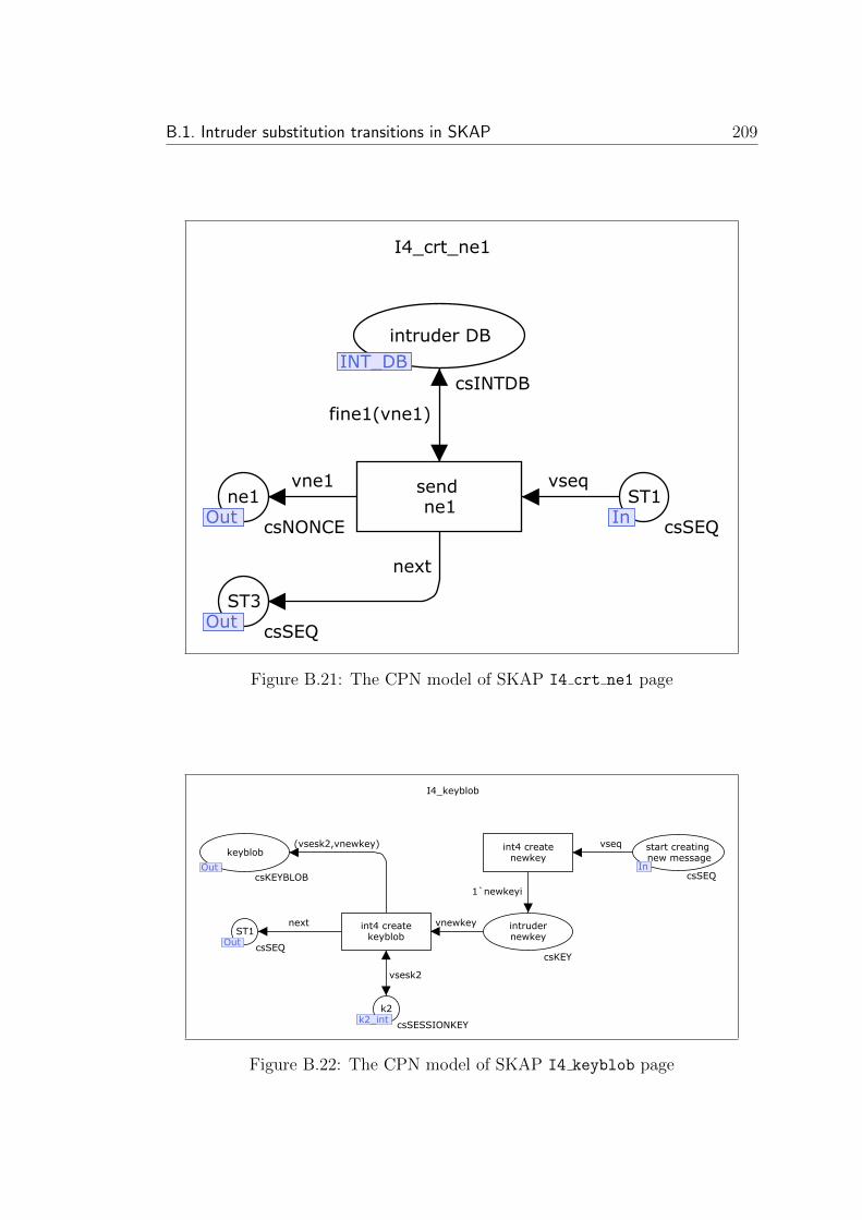
B.1. Intruder substitution transitions in SKAP 209
I4_crt_ne1
vseq
fine1(vne1)
vne1
next
send ne1
intruder DB
INT_DB
csINTDB
ne1Out
csNONCE
ST1In
csSEQ
ST3Out
csSEQOut
InOut
INT_DB
Figure B.21: The CPN model of SKAP I4 crt ne1 page
I4_keyblob
vseq
vsesk2
vnewkey
1`newkeyi
(vsesk2,vnewkey)
next
int4 createnewkey
int4 createkeyblob
k2k2_int
csSESSIONKEY
intrudernewkey
csKEY
keyblob
OutcsKEYBLOB
start creating new message
IncsSEQ
ST1Out
csSEQOut
InOut
k2_int
Figure B.22: The CPN model of SKAP I4 keyblob page
210 Appendix B. Appendix: SKAP CPN model
B.2 User substitution transitions in SKAP
There are a number of transitions designed to process messages sent or received
by the user. The U1 creates the message sent to the TPM in the first ex-
change. The TPM response to this message is processed by U2. Then U3 creates
TPM CreateWrapKey and sends it to the TPM. Its answer is finally processed by
U4. The UKeys substitution transition is designed to create user session keys K1
and K2. In the next sub-sections these substitution transitions are illustrated.
B.2.1 The U1 functionality
The U1 page(Figure B.23), is the first model page that is enabled. The sequence
token is stored in ‘start session’ as its initial marking. The existence of this
token with user1 value enables the ‘Start creating exchange 1’ transition.
So its border is thicker than the other transitions and places. The ‘Generate
Session Secret(S)’ transition creates the session secret S and stores it in place
S as a member of global fusion set s user. The ‘Encrypt Session Secret (S)
using RSA OAEP’ transition after fetching public key part of parent key han-
dle from ‘Public Key of Loaded key’ place encrypts the shared secret S and
stores the result in ‘Enc. Session Secret’ place. The connected double arc
to the ‘Encrypt Session Secret (S) using RSA OAEP’ enables it infinitely.
To prevent this problem and to enable the transition just once the JO place
with only one token (with ‘JO’ value) is used. Increasing the number of initial
marking tokens can increase the number of times that transition will be enabled.
The token of encrypted session secret (vss, vpubkey) will be stored in ‘Enc.
Session Secret’ place. Transition ‘Send TPM SKAP() message’ by putting
pkh token and vess in one token creates TPM SKAP (pkh, Spk(pkh)) then by
adding CNEXT USER1 and cCONFIG to determine the next page after U1 and the
current configuration of model (either COMMCH or INTRUDER) creates the out-
put token (vpkh, vess, cNEXT USER1, cCONFIG) and sends it toward either
intruder or TPM from ‘sent TPM SKAP message’ output port.

B.2. User substitution transitions in SKAP 211
vseq
vseq
vseq
vjo
vess
(vss,vpubkey)
vpubkey
vss
1`s
vpkh
Start creatingexchange 1
[vseq=user1]
Encrypt SessionSecret (S) using
RSA_OAEP
csSEQ
1`jo
csSEQ
csESS
Public key ofLoaded key
pk_pkh_user
1`pk_pkh_pub
csTPMKEY
Ss_user
csSS
1`pkh
csPKH
start session
IncsSEQ
csSKAP_MSG
In
s_user
pk_pkh_user
[vseq=user1]
Generate SessionSecret (S)
start exchangeone
JO
Enc. Session Secret
Send TPM_SKAP()message
pkhpkh_userpkh_user
sent TPM_SKAPmessage
OutOut
(vpkh,vess, cNEXT_USER1, cCONFIG)
1
1
1
1
Figure B.23: The CPN model of SKAP U1 page
B.2.2 The U2 functionality
The U2 substitution transition (Figure B.24 ) stores the received response of
TPM to the TPM SKAP (pkh, Spk(pkh)) from input port in ‘rec. TPM SKAP
response’ place. The ‘Store TPM SKAP() Response Parts’ transition stores
input message parts ah and ne in ah and ne places. The ah and ne will be used
later to create SKAP Msg#3 message. So U2 transition stores them in ah user and
ne user global fusion sets for later usages. The sequence token with userkeycrt
colour is moved to the next CPN page to create the user K1 and K2 keys.
B.2.3 The Ukeys functionality
The Ukeys module (Figure B.25) creates K1 and K2 for user. The ‘Create
User K1’ transition fetches ne, ad(pkh) S and constant 1 from ne, ad pkh user,
S and c1 places and after using them to create vss, vad pkh, vne, c1 output

212 Appendix B. Appendix: SKAP CPN model
(vah,vne, vseq,vcfg)
1`userkeycrt
vnevah StoreTPM_SKAP()
Response Parts
[vseq=user2]
nene_user
csNONCE
ahah_user
csAH
Start User key creation
OutcsSEQ
rec. TPM_SKAPresponse
IncsSKAP_RES
In
Out
ah_user ne_user
Figure B.24: The CPN model of SKAP U2 page
token (which is K1 = hmacS(ad(pkh), ne, 1)) returns all of them (except c1
which is not used later) to their places for future usage. The ‘Create User
K2’ transition creates (K2 = hmacS(ad(pkh), ne, 2)) by fetching required tokens
from ne, ad pkh user, S and c2 places. The created (vss, vad pkh, vne, c2)
token is stored in K2 place, as a member of k2 user global fusion set, for further
usage by other pages of model.
B.2.4 The U3 functionality
The U3 module (Figure B.26) is responsible of creating TPM CreateWrapKey
message of SKAP Msg#3. Three different sections of model create ah, pkh, no,
encK2(newauth) and hmacK1(null, ne, no). They are stored in ‘TPM CRTWK’,
Enc(newauth) and hmac(null, ne, no) places. Finally, ‘send TPM CRTWK’

B.2. User substitution transitions in SKAP 213
vss
vss
vad_pkh vad_pkh
vne vne
vseq1`user3
(vss, vad_pkh,vne,c2)
vconst2
(vss, vad_pkh,vne,c1)
vseq vseq
vconst1
Create User K1
[vseq=userkeycrt]
Create User K2
Ss_user
csSS
ad_pkh_user
ad_pkh_user
1`ad_pkh_pub
csAUTH_DATA
nene_user
csNONCE
K2k2_user
csSESSIONKEY
c2
1`c2
csCONST
K1k1_user
csSESSIONKEY
ST1
csSEQ
c1
1`c1
csCONST
End Userkey creation
OutcsSEQ
Start User key creation
IncsSEQ
InOut
k1_userk2_user
ne_user
ad_pkh_user
s_user
1
1 1
Figure B.25: The CPN model of SKAP UKeys page
transition puts all the tokens in (vcrtwk, vencauth, vhmac, cNEXT USER3,
cCONFIG) and stores it in ‘sent TPM CRTWK message’ place to be ssent to other
pages through output port. In the first section ‘Create TPM CrtWrapkey’ tran-
sition fetches required tokens and creates the ah, pkh, no part. In the second sec-
tion ‘Encrpt newauth’ fetches vnewauth and vsesk2 and creates encK2(newauth).
In the last section ‘Create hmac’ fetchesK1, null, ne, and no to create (vsesk1,
vnull, vne, vno) and stores it in hmac(null, ne, no) place for further usage
by ‘send TPM CRTWK’;
B.2.5 The U4 functionality
The input token of the U4 page (Figure B.27) is stored in ‘Rec CRTWK response’
input port. The [vseq=user4] guard of ‘Process TPM CRTWK Response’ tran-
sition is used to implement sequence token mechanism. The fields of input
token are extracted by ‘Extract Fields’ transition. They will be stored in
‘ne1 User’, ‘Received Hmac’ and keyblob places. Then user regenerates
the HMAC by ‘Create hmac’ transition and using the stored tokens in no,
K1 and null places. The result is stored in hmac(K1, null, ne1, no) place.
The ‘Compare Hacs’ place compares the input hmac in ‘Received Hmac’ place
with regenerated hmac. The comparison result is stored by ‘if vhmac1=vhmac2
then correct hmac2 else incorrect hmac2’ inscription in error1 place. If
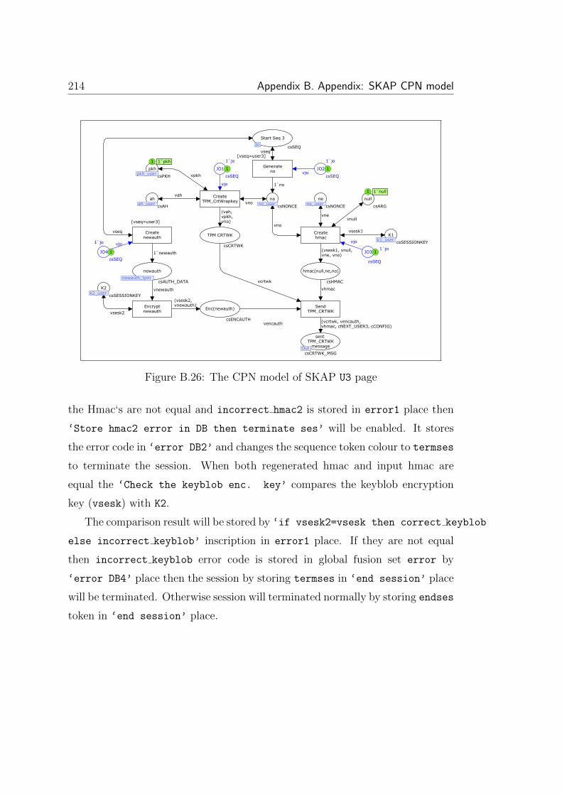
214 Appendix B. Appendix: SKAP CPN model
vjovjo
vjo
vjo
vseq
vcrtwk
vhmac
vencauth (vcrtwk, vencauth, vhmac, cNEXT_USER3, cCONFIG)
(vsesk1, vnull, vne, vno)
vsesk1
vnull
vno
vne
(vsesk2,vnewauth)
vsesk2
vnewauth
1`newauth
(vah,vpkh,vno)
vseq
vah
vpkh
vno
1`no
SendTPM_CRTWK
Createhmac
Encryptnewauth
Createnewauth
[vseq=user3]
Generateno
[vseq=user3]
CreateTPM_CrtWrapkey
JO4
1`jo
csSEQ
JO2
1`jo
csSEQ
JO1
1`jo
csSEQ
JO31`jo
csSEQ
hmac(null,ne,no)
csHMAC
K1k1_user
csSESSIONKEY
null
1`null
csARG
nene_user
csNONCE
Enc(newauth)
csENCAUTH
K2k2_user
csSESSIONKEY
newauth
newauth_tpmcsAUTH_DATA
TPM CRTWK
csCRTWK
ahah_user
csAH
nono_user
csNONCE
pkhpkh_user
1`pkh
csPKH
Start Seq 3
IncsSEQ
sent TPM_CRTWK
messageOutcsCRTWK_MSG
Out
In
pkh_user
no_userah_user
newauth_tpm
k2_user
ne_user
k1_user
1
11
1
1 1`null
1 1`pkh
Figure B.26: The CPN model of SKAP U3 page
the Hmac‘s are not equal and incorrect hmac2 is stored in error1 place then
‘Store hmac2 error in DB then terminate ses’ will be enabled. It stores
the error code in ‘error DB2’ and changes the sequence token colour to termses
to terminate the session. When both regenerated hmac and input hmac are
equal the ‘Check the keyblob enc. key’ compares the keyblob encryption
key (vsesk) with K2.
The comparison result will be stored by ‘if vsesk2=vsesk then correct keyblob
else incorrect keyblob’ inscription in error1 place. If they are not equal
then incorrect keyblob error code is stored in global fusion set error by
‘error DB4’ place then the session by storing termses in ‘end session’ place
will be terminated. Otherwise session will terminated normally by storing endses
token in ‘end session’ place.

B.3. TPM substitution transitions in SKAP 215
endses
verr
verrverr
if vsesk2=vsesk then correct_keyblobelse incorrect_keyblob
vsesk2
(vsesk, vkey)
verr
termses
verr
verr
if vhmac1 = vhmac2 then correct_hmac2else incorrect_hmac2
vkeyblob
vhmac1
vhmac2
vne1
(vsesk1, vnull,vne1, vno)vsesk1
vnull
vno
vhmacvne1
(vkeyblob,vne1,vhmac,vseq, vcfg)
(vkeyblob,vne1,vhmac,vseq, vcfg)
(vkeyblob,vne1,vhmac,vseq, vcfg)
end session
[verr=correct_keyblob]
Store keybloberror in DB thenterminate ses
[verr=incorrect_keyblob]
Check thekeyblob enc.
key
[verr = correct_hmac2]
Store hmac2 error in DB thenterminate ses
[verr=incorrect_hmac2]
CompareHmacs
Createhmac
Extract Fields
ProcessTPM_CRTWP
Response
[vseq=user4]
error 1
csERROR
error DB4
errorcsERROR
K2k2_user
csSESSIONKEY
error DB2
errorcsERROR
error1
csERROR
keyblob
csKEYBLOB
hmac(K1, null, ) dup stringwidth pop 2 div neg 0 rmoveto shownewpath 46.000000 -14.000000 moveto(ne1, no)
csHMAC
K1k1_user
csSESSIONKEY
null
1`null
csARG
no
no_user csNONCE
Received Hmac
csHMAC
ne1 User
csNONCE
Rec CRTWK response
TmpcsCRTWK_RES
end session
OutcsSEQ
Rec CRTWKresponse
IncsCRTWK_RES
In
Out
no_user
k1_user
error
k2_user
error
Figure B.27: The CPN model of SKAP U4 page
B.3 TPM substitution transitions in SKAP
TPM is interacting with either user or intruder to process received messages or
create TPM responses. In the TPM page of Figure 4.12 substitution transi-
tion ‘Process TPM SKAP()’ (page T1) processes the input message from ‘rcvd
TPM SKAP message’ input port.
The response to this message is produced by ‘Send TPM SKAP Response’
substitution transition (page T2). Before sending this message to the output
‘sent TPM SKAP response2’, the session keys K1 and K2 are produced in the
TPM side by ‘Create TPM Keys’ substitution transition in page TKeys of the
model. The ‘Process TPM CreateWK’ substitution transition implemented in
page T3 processes the TPM CreateWrapKey message and sends the response to it
by ‘Send TPM CreateWK Response’ substitution transition. The details of T1,
T2, TKeys, T3 and T4 pages are illustrated in the next sub-sections.

216 Appendix B. Appendix: SKAP CPN model
B.3.1 The T1 functionality
The input token to the T1 page (Figure B.28) is stored in ‘rec. TPM SKAP
message’ input port. Then after controlling the sequence token value by [vseq=tpm1]
guard the input message parts will be extracted by ‘Store TPM SKAP() parts’
transition. The extracted user pkh will be compared with TPM pkh (stored in
pkh tpm global fusion set) by ‘compare pkh of tpm and user’ the result error
token will be stored in error place. If the user and TPM pkh was not equal then
incorrect pkh1 will be stored in ‘error DB1’ place and session will be termi-
nated, otherwise the ‘check decryption Key’ transition will compare the de-
cryption key of vess with sk pkh pri using if decryptionKey(vpubkey)=sk pkh pri
then correct enc1 else incorrect enc1 inscription. If they were unequal
then incorrect enc1 error code will be stored in error global fusion set and
session will be terminated. Otherwise, the decrypted session secret vss will be
stored in place S(member of s tpm fusion set). Then by changing sequence token
value to 1`tpm2 the next TPM process (page T2) will be run.
(vpkh,vess, vseq,vcfg)
verr
vskey
vpkh2
vjo
verr
verr
(vss, vpubkey)
if decryptionkey(vpubkey) = sk_pkh_pri then correct_enc1else incorrect_enc1
verr
verr
verr
if vpkh1=vpkh2 then correct_pkh1else incorrect_pkh1
vpkh1
vess
vess
vess
1`tpm2
(vss,vpubkey)
(vpkh,vess, vseq,vcfg)
vss
(vpkh,vess,vseq,vcfg)
vpkh
Store encryption related error in DB and terminate ses
[verr =incorrect_enc1]
check decryptionkey
Store pkh relatederror in DB thenterminate ses
[verr = incorrect_pkh1]
compare pkh oftpm and user
compare tpm and user pkh
[verr=correct_pkh1]
Process TPM_SKAP()
[vseq=tpm1]
Dec. SessionSecret
[verr = correct_enc1]
Store TPM_SKAP()
Parts
[vseq=tpm1]
JO
1`jo
csSEQ
error2
csERROR
error DB1
errorcsERROR
error
csERROR
Enc Session Secret1
csESS
pkhpkh_tpm
1`pkh
csPKH
secret key ofLoaded key1
pk_pkh_pri
1`sk_pkh_pri
csTPMKEY
Ss_tpm
csSS
Tmp. TPM_SKAPmessage
csSKAP_MSG
receivedpkh
csPKH
rec. TPM_SKAPmessage
In
csSKAP_MSG
Start Seq 2
OutcsSEQ
Out
In
s_tpm
pk_pkh_pri
pkh_tpm
error
csESSEnc Session
Secret2
1 1
1
Figure B.28: The CPN model of SKAP T1 page

B.3. TPM substitution transitions in SKAP 217
B.3.2 The T2 functionality
The T2 page (Figure B.29) creates a new nonce ne and authorisation handle
ah. Then stores them in ne tpm and ah tpm global fusion sets for future TPM
usage. In the next step the TPM SKAP response is created and is stored in
‘sent TPM SKAP response1’ output port. Assigning 1`tpmKeycrt value to the
sequence token will enable Tkeys page to create K1 and K2 TPM session keys.
1`ne
vjo
1`tpmkeycrt
vseq
1`ah
(vah,vne, tpmkeycrt, cCONFIG)
vne
vah
Create ne and ah of the session
[vseq=tpm2]
Create and sendTPM_SKAP response
JO1
1`jo
csSEQ
ah
ah_tpm csAH
nene_tpm
csNONCE
sent TPM_SKAPresponse1
OutcsSKAP_RES
Start TPM key creation
OutcsSEQ
Start Seq 2
IncsSEQ
In
OutOut
ne_tpm ah_tpm
1
Figure B.29: The CPN model of SKAP T2 page

218 Appendix B. Appendix: SKAP CPN model
B.3.3 The Tkeys functionality
In the Tkeys page (Figure B.30) ‘Create TPM K1’ and ‘Create TPM K2’ tran-
sitions create K1 and K2 using tokens in ne, ad pkh tpm and S places. The result
will be stored in K1 and K2 places. The tokens of these places will be accessible
for all the TPM pages by k1 tpm and k2 tpm global fusion sets.
vss vss
vne vne
vad_pkh vad_pkh
(vss, vad_pkh, vne, vconst2)
(vss, vad_pkh, vne, vconst1)
vseqcNEXT_TPM2 vseq vseq
vconst2 vconst1
Create TPM K2
Create TPM K1
[vseq=tpmkeycrt]
Ss_tpm
csSS
nene_tpm
csNONCE
ad_pkh_tpm
ad_pkh_tpm
1`ad_pkh_pub
csAUTH_DATA
K2k2_tpm
csSESSIONKEY
K1k1_tpm
csSESSIONKEY
c2
1`c2
csCONST
c1
1`c1
csCONST
ST1
csSEQ
End TPM key creation
OutcsSEQ
Start TPM key creation
In csSEQInOut
k1_tpmk2_tpm
ad_pkh_tpm
ne_tpm
s_tpm
1
1 1
Figure B.30: The CPN model of SKAP Tkeys page
B.3.4 The T3 functionality
The T3 page (Figure B.31) like other pages at first extracts message parts (using
‘Extract TPM CRTWK’ and ‘Extract ah, pkh, no’ places). Then the following
integrity checks will be applied on different parts of received message:
1. The ‘Compare ahs’ compares the received ah vah1 with the TPM ah in
‘tpm ah’ place. Based on the comparison result correct ah or incorrect ah
token will be stored in error1 place. When both TPM and user ah are
equal the other parts of message will be compared and next integrity check
will be applied, otherwise session will be terminated by storing termses
and incorrect ah tokens in ‘Start Seq 4’ and ‘error DB1’ places.
2. The ‘compare pkhs’ transition will compare stored TPM pkh in pkh
place with received pkh (available in ‘rec. pkh’ place). The compar-
ison result is stored in error2 place. If the pkh values are not equal then

B.3. TPM substitution transitions in SKAP 219
incorrect pkh2 is stored in global error fusion set and session will be ter-
minated. Otherwise, the ‘correct pkh2’ token will be stored in error2
and the next integrity check will be done.
3. The ‘Compare Rec. K2 and stored K2’ transition will compare the stored
TPM session secret (K2) in K2 tpm fusion set with session secret stored to-
ken in Enc(newauth). If they were both equal the next step of model will
be started. Otherwise, the incorrect newauth error code will be stored
in error global fusion set through ‘error DB1’ place then session will be
terminated.
4. The ‘Compare Hmacs’ place compares the received hmac in ‘Received
Hmac’ place with computed hamc by ‘Create hmac’ transition. The re-
sult of comparison (correct hmac1 or incorrect hmac1) will be stored in
error4 place. When incorrect hmac1 as the result of unequal hmacs is
produced, the error code and termses tokens will be stored in error fusion
set and ‘Start Seq 4’ output port, then session will be terminated.
tpm4
termses
termses
termses
(vcrtwk, vencauth,vhmac, vseq,vcfg)
vseq
1`next
(vsesk2,vnewauth)
vnewauth
verr
verr
verr
if vsesk=vsesk2 then correct_newauthelseincorrect_newauth
vsesk
verr
vencauth
verr
verr
verr
if vpkh1=vpkh2 then correct_pkh2else incorrect_pkh2
vpkh2
vpkh1
verr
verr
verr
if vah1=vah2 then correct_ahelse incorrect_ah
vah1
vah2
vno
vah
vpkh if vhmac1=vhmac2 then correct_hmac1else incorrect_hmac1
vhmac2
vne
vsesk1
vhmac
vhmac1
vnull
vno
(vah,vpkh, vno)
vcrtwk
DecryptEnc(newauth)
[verr=correct_newauth]
Store newauth related error in
DB then terminate
[verr=incorrect_newauth]
Start creating exchange 4
[verr = correct_hmac1]
Store hmac relatederror in DB thenterminate ses
[verr=incorrect_hmac1]
Compare Rec. K2 andstored K2
[verr=correct_pkh2]
Store pkh relatederror in DB thenterminate ses
[verr=incorrect_pkh2]
comparepkhs
[verr=correct_ah]
Store ah relatederror in DB thenterminate ses
[verr = incorrect_ah]
Compareahs
CompareHmacs
Createhmac
[verr=correct_newauth]
Extract ah, pkh, no
Extract TPM_CRTWK
ProcessTPM_CRTWK
[vseq=tpm3]
ST1
csSEQ
error3
csERROR
TPM K2k2_tpm
csSESSIONKEY
newauth
csAUTH_DATA
Enc(newauth)
csENCAUTH
error2
csERROR
pkhpkh_tpm
1`pkh
csPKH
error1
csERROR
error DB1
errorcsERROR
tpmah
ah_tpm csAH
no2no_tpm
csNONCE
rec ah
csAH
rec.pkh
csPKH
error4
csERROR
nene_tpm
csNONCE
K1k1_tpm
csSESSIONKEY
Received Hmac
csHMAC
hmac(null,ne,no)
csHMAC
null
1`null
csARG
nono_tpm
csNONCE
TPM CRTWK
csCRTWK
Rec CRTWKmessage
Tmp
csCRTWK_MSG
Start Seq 4
OutcsSEQ
Rec Cmdmessage
IncsCRTWK_MSG
In
Out
no_tpm
k1_tpm
ne_tpm
no_tpm
ah_tpm
error
pkh_tpm
k2_tpm
(vcrtwk, vencauth,vhmac, vseq, vcfg)
(vsesk1,vnull,vne,vno)
verr
(vsesk2,vnewauth)
verr
(vcrtwk, vencauth,vhmac, vseq,vcfg)
1
1
Figure B.31: The CPN model of SKAP T3 page
The creation of correct hmac1 as the result of hmac comparison will en-
able the ‘Start creating exchange 4’ transition. This transition by assigning

220 Appendix B. Appendix: SKAP CPN model
tpm4 to the sequence token will enable the next TPM page to start the exchange
between TPM and user.
B.3.5 The T4 functionality
In the T4 page (Figure B.32) ‘Generate ne1’, ‘Create hmac’ and ‘Create
keyblob’ transitions create n′e, hmacK1(null, n
′e, no, ...) and keyblob parts of
last exchange. The results are stored in ne1, hmac(K1, null, ne1, no) and
keyblob places. The ‘Create & send TPM CRTWK Response’ transition com-
poses 1, 2 and 3 to create the final message and by storing it in ‘sent Cmd
response’ output port sends it to the user.
next
next
(vsesk2,vnewkey)
vnewkey
vsesk2
1`ne1
vseq
(vkeyblob, vne1, vhmac, cNEXT_TPM4, cCONFIG)
vkeyblob
vne1
vhmac
vno
(vsesk1, vnull,vne1, vno)
vsesk1
vne1
vnull
Create KeyblobGenerate
ne1
[vseq=tpm4]
Create & sendTPM_CRTWK
Response
Createhmac
start creatingkeyblob
csSEQ
newkey
1`newkey
csKEY
K2k2_tpm
csSESSIONKEY
keyblob
csKEYBLOB
nono_tpm
csNONCE
hmac(K1, null,) dup stringwidth pop 2 div neg 0 rmoveto shownewpath 44.000000 -14.000000 moveto(ne1, no)
csHMAC
K1k1_tpm
csSESSIONKEY
ne1ne1_tpm
csNONCE
null
1`null
csARG
Start Seq 4
IncsSEQ
sent Cmdresponse
OutcsCRTWK_RES
Out
In
ne1_tpm
k1_tpm no_tpm
k2_tpm
1
1`newkey
1
Figure B.32: The CPN model of SKAP T4 page

Appendix C
Appendix: Oblivious Transfer
Protocol CPN model
The required steps for modelling and analysing properties of a TPM-based pro-
tocol are illustrated in Chapter 5. This appendix provides more detail about the
model colour sets, variables and CPN pages.
C.0.6 Colour set definition
The used colour sets to implement CPN model are listed in Figure C.1. The first
four colour sets are standard colour sets that are available in all the CPN models
designed using CPN/Tools. Other colour sets are illustrated briefly.
221

222 Appendix C. Appendix: Oblivious Transfer Protocol CPN model
01 colset UNIT = unit;
02 colset INT = int;
03 colset BOOL = bool;
04 colset STRING = string;
05 colset csSEQ = with
tpm1 | tpm2 | tpm3 | bob_int1 | bob_int2 | bob_int3 |
alice1 | jo | start_protocol | chg_cmt | endses | next;
06 colset csERROR = with
s1_opened_by_dec | s2_s1_extended | s2_opened_by_dec |
s1_s2_extended | try_opening_s1 | try_opening_s2 | no_error;
07 colset csPUBKEY = with pubk_k1 | pubk_k2 | nopub_k;
08 colset csSECRET = with s1 | s2 | commited | not_commited;
09 colset csPRIKEY = with prik_k1 | prik_k2 | nopri_k;
10 colset csINARG_CERTIFY_KEY = with
arg_certkey1 | arg_certkey2;
11 colset csPCR_EXTENDED = BOOL;
12 colset csTPM_CertifyKey_Msg = product
csINARG_CERTIFY_KEY * csINARG_CERTIFY_KEY * csSEQ;
13 colset csCERT = with cert1 | cert2;
14 colset csPCR_INIT = with u0;
15 colset csBOBINTERACT = with started | ended;
16 colset csPCR_VALUE = with a1 | a2;
17 colset csPCR_DIGEST = product
csPCR_INIT * csPCR_VALUE;
18 colset csTPM_CertifyKey_Res = product
csCERT * csPCR_DIGEST;
19 colset csTPM_CertifyKey_Res_Msg = product
csTPM_CertifyKey_Res *
csTPM_CertifyKey_Res * csSEQ;
20 colset csDbl_Cert_Msg = product
csCERT * csCERT * csSEQ;
21 colset csENC_S = product
csPUBKEY * csSECRET;
22 colset csDblSecrets_Msg = product
csENC_S * csENC_S * csSEQ;
23 colset csTPM_EXTEND = with tpm_extend_args;
24 colset csTPM_EXTEND_RES = with tpm_extend_res;
25 colset csTPM_UNBIND = with tpm_unbind_args;
26 colset csTPM_UNBIND_RES = with tpm_unbind_res;
27 colset csINTDB = union
fipub_key1 : csPUBKEY +
fipub_key2 : csPUBKEY +
fipri_key1 : csPRIKEY +
fipri_key2 : csPRIKEY +
fis1 : csSECRET +
fis2 : csSECRET;
Figure C.1: The list of model colour sets
05 colset csSEQ = with
tpm1 | tpm2 | tpm3 | bob_int1 | bob_int2 | bob_int3 | alice1 |
jo | start_protocol | chg_cmt | endses | next;
This colour set is designed to implement sequence token mechanism. As il-
lustrated in Section 4.1.3, this mechanism prevents concurrent run of protocol
sessions and pages, thus decreases the possibility of state space explosion.

223
06 colset csERROR = with
s1_opened_by_dec | s2_opened_by_dec | s2_s1_extended |
s1_s2_extended | try_opening_s1 | try_opening_s2 | no_error;
This colour set implements the error-discovery mechanism. Depending on the
intruder malicious action, suitable colour is selected from this colour set and after
assigning it to the error token result will be stored in a global fusion set. For
example, when intruder opens the first secret, S1, the s1 opened by dec colour
will be assigned to the error token and the result will be stored in error global
fusion set.
08 colset csSECRET = with S1 | S2 | commited | not_commited;
This colour set is designed to define the protocol secrets, S1 and S2. The
committed and not commited colours are used to demonstrate whether Alice
(sender) has committed to the secrets or not.
07 colset csPUBKEY = with pubk_k1 | pubk_k2 | nopub_k;
This colour set defines public key part of the stored keys in TPM. For imple-
mentation requirements the nopub k colour set is defined that means the public
part of the key without public key.
09 colset csPRIKEY = with prik_k1 | prik_k2 | nopri_k;
This colour set defines private key part of the stored keys in TPM. For imple-
mentation requirements the nopri k colour set is defined that means the private
part of the key without private key.
10 colset csINARG_CERTIFY_KEY = with arg_certkey1 | arg_certkey2;
This colour set is defined to demonstrate the input parameters of the sent
TPM Certifykey commands to the TPM by Bob. The details of the parame-
ters are not important for the analysis so only one colour set member for whole
the arguments has been considered.
11 colset csPCR_EXTENDED = BOOL;

224 Appendix C. Appendix: Oblivious Transfer Protocol CPN model
This colour set is used as a flag to demonstrate whether the PCR is extended
or not. After extending the PCR a token of this colour set and TRUE colour will
be stored in a global fusion set to prevent further extensions. The default colour
for the stored token in the global fusion set is FALSE.
12 colset csTPM_CertifyKey_Msg = product
csINARG_CERTIFY_KEY * csINARG_CERTIFY_KEY * csSEQ;
The first message sent from Bob to the TPM is names Msg1. The colour set of this
message is csTPM CertifyKey Msg that is the product of two TPM Certifykey
command arguments and one csSEQ (to implement the sequence token mecha-
nism) colour set.
13 colset csCERT = with cert1 | cert2;
This colour set is designed to model tokens carrying certificates between protocol
principals.
14 colset csPCR_INIT = with u0;
This colour set is defined to assign initial colour to the PCR.
15 colset csBOBINTERACT = with started | ended;
When TPM starts an interaction with Bob a token of colour set csBOBINTERACT
with started colour will be stored in designated place. At the end of the TPM
interaction with Bob the previous start token is removed from the place and a
new token with colour ended will be stored in place.
16 colset csPCR_VALUE = with a1 | a2;
This colour set defines the values (a1 and a2) that can be assigned to the PCR.
17 colset csPCR_DIGEST = product
csPCR_INIT * csPCR_VALUE;

225
This colour set defines the HMAC result of PCR extension. To extend PCR,
its initial value and the value that will be assigned to the PCR at the end are
important so the csPCR DIGEST is the product of csPCR INIT and csPCR VALUE
colour sets.
18 colset csTPM_CertifyKey_Res = product
csCERT * csPCR_DIGEST;
The TPM response to the TPM Certifykey command is sent to the Bob using
tokens with this colour set.
19 colset csTPM_CertifyKey_Res_Msg = product
csTPM_CertifyKey_Res * csTPM_CertifyKey_Res * csSEQ;
The TPM response to the first message is returned to Bob using second protocol
message. It contains certificates, the values they are locked to and the part that
implements sequence token mechanism.
20 colset csDbl_Cert_Msg = product
csCERT * csCERT * csSEQ;
This colour set is designed to transfer third protocol message that contains two
certificates.
21 colset csENC_S = product
csPUBKEY * csSECRET;
To encrypt each secret, the secret value and the used public key for encryption are
required. So this colour set is defined as the product of csPUBKEY and csSECRET.
22 colset csDblSecrets_Msg = product
csENC_S * csENC_S * csSEQ;
This colour set defines the forth protocol message.
23 colset csTPM_EXTEND = with
tpm_extend_args;
226 Appendix C. Appendix: Oblivious Transfer Protocol CPN model
This colour set is used to model sent TPM Extend command from Bob to the
TPM.
24 colset csTPM_EXTEND_RES = with
tpm_extend_res;
This colour set returns the answer token of the TPM to the TPM Extend com-
mand.
25 colset csTPM_UNBIND = with
tpm_unbind_args;
This colour set is used to model sent TPM Unbind command from Bob to the
TPM.
26 colset csTPM_UNBIND_RES = with
tpm_unbind_res;
This colour set returns the answer token of the TPM to the TPM Unbind com-
mand.
27 colset csINTDB = union
fipub_key1 : csPUBKEY +
fipub_key2 : csPUBKEY +
fipri_key1 : csPRIKEY +
fipri_key2 : csPRIKEY +
fis1 : csSECRET +
fis2 : csSECRET;
This colour set is defined to store intruder knowledge in a global fusion set.
Secrets, private and public parts of the different keys can be stored in intruder
database.
The list of the defined variables using previous colour sets is shown in Figure
C.2

227
var vseq, vjo:csSEQ;
var verr : csERROR;
var varg_certifykey1,
varg_certifykey2 : csINARG_CERTIFY_KEY;
var vcert1, vcert2:csCERT;
var vpcr_digest1,
vpcr_digest2:csPCR_DIGEST;
var vtpm_certifykey_res1 ,
vtpm_certifykey_res2 :
csTPM_CertifyKey_Res;
var vTPM_CertifyKey_Res_Msg :
csTPM_CertifyKey_Res_Msg;
var vsec1, vsec2, vsec3 : csSECRET;
var vpub_key1, vpub_key2 :csPUBKEY;
var vpri_key1, vpri_key2 : csPRIKEY;
var venc_s1, venc_s2 : csENC_S;
var vtpm_extend:csTPM_EXTEND;
var vtpm_extend_res:csTPM_EXTEND_RES;
var vbinteract : csBOBINTERACT;
var vtmp_unbind : csTPM_UNBIND;
var vpcr_extended :csPCR_EXTENDED;
var vtpm_unbind_res : csTPM_UNBIND_RES;
var vmsg1:csTPM_CertifyKey_Msg;
var vmsg2:csTPM_CertifyKey_Res_Msg;
var vmsg3:csDbl_Cert_Msg;
var vmsg4:csDblSecrets_Msg;
Figure C.2: The list of the TPM secrecy model variables
C.0.7 CPN model pages
The B I1 page functionality
The ‘Send TPM Certify Key’ transition of this page (Figure C.3) simply creates
first protocol message, then by storing it in ‘sent TPM CertifyKey’ output port
sends it to the TPM.
B_I1 page
(arg_certkey1, arg_certkey2, tpm1)
vseq
Send TPM_Certify_Key
[vseq=start_protocol]
Start
In
1`start_protocol
csSEQ
sentTPM_CertifyKey
Out
csTPM_CertifyKey_Msg
Out
In
Figure C.3: The first page of the Bob CPN model

228 Appendix C. Appendix: Oblivious Transfer Protocol CPN model
The TPM1 page functionality
This page (Figure C.4) creates certificates and the values that they are locked to
them. The results are stored in ‘TPM CertifyKey Response 1’ and ‘TPM CertifyKey
Response 2’ places. Then after combining with bob int2 sequence token will
be sent to the Bob from ‘sent TPM CertifyKey Response’ output port.
TPM1 page
(varg_certifykey1, varg_certifykey2, vseq)
(vtpm_certifykey_res1,vtpm_certifykey_res2,bob_int2)
vtpm_certifykey_res1
vtpm_certifykey_res2
(vcert2,vpcr_digest2)
(vcert1, vpcr_digest1)
vcert2
vpcr_digest2
vpcr_digest1
vcert1
1`next
1`(u0,a2)
1`(u0,a1)
1`next
1`cert2
1`cert1
1`next
1`next
1`next
1`next
Create ResponseTPM_CertifyKey2
Create ResponseTPM_CertifyKey1
Create TPM_CertifyKey
Response Message
Create Cert1, Cert2, PCR_Digest_1 and
PCR_Digest_2
Sign HASH(public key, related params)
using AIK
Process TPM_CertifyKey
[vseq=tpm1]
TPM_CertifyKeyResponse 2
csTPM_CertifyKey_Res
TPM_CertifyKeyResponse 1
csTPM_CertifyKey_Res
Start creatingTPM_CerifyKey
ResponsescsSEQ
PCR_Digest_2
csPCR_DIGEST
PCR_Digest_1
csPCR_DIGEST
Certificate_2
csCERT
Certificate_1
csCERT
Start CertCreation
csSEQ
Start Signing
csSEQ
rcvdTPM_CertifyKey
IncsTPM_CertifyKey_Msg
sentTPM_CertifyKey
ResponseOut
csTPM_CertifyKey_Res_Msg
Out
In
Figure C.4: The first page of the TPM CPN model
The B I2 page functionality
This page (Figure C.5) after extracting TPM CertifyKey responses stores them
in ‘TPM CertifyKey Response 1’ and ‘TPM CertifyKey Response 2’ places.
Then by combining both of the received certificates and alice1 sequence token
in one token, stores the result in ‘sent certificates’ output port.
The Alice page functionality
In this page (Figure C.6) Alice at first stores a token with colour started in
the interact bob started place to demonstrate an interaction commencement
with Bob. Then after extracting certificates and storing them in ‘Certificate
1’ and ‘Certificate 2’ places commits to the S1 and S2 secrets. After secret

229
B_I2 page
(vtpm_certifykey_res1,vtpm_certifykey_res2,vseq)
(vcert1, vcert2, alice1)
vcert1 vcert2
vcert1vcert2
(vcert1, vpcr_digest1)(vcert2, vpcr_digest2)
vtpm_certifykey_res2vtpm_certifykey_res1
sendCertificate1 and
Certificate2
verifyCertificate1 and
Certificate2
processTPM_CertifyKey
Response Message
[vseq=bob_int2]
Certificate 1
csCERT
Certificate 2
csCERT
TPM_CertifyKeyResponse 2
csTPM_CertifyKey_Res
TPM_CertifyKeyResponse 1
csTPM_CertifyKey_Res
receivedTPM_CertifyKey
ResponseIn
csTPM_CertifyKey_Res_Msg
sentcertificates
OutcsDbl_Cert_Msg
Out
In
Figure C.5: The second page of the Bob CPN model
commitment, Alice stores a token with committed colour in secret commitment
place. The marking of this place is used in ASK-CTL formulas to find the
marking from that Alice has committed to the secrets. Secrets are encrypted
by ‘Encrypt S1 and S2’ and finally will be transmitted to Bob through ‘Sent
Encrypted Secrets’ output port. At the end of the interaction with Bob,
a token with ended colour will be stored in interact bob ended. As both
interact bob started and interact bob ended are members of the B INTERACT
global fusion set, storing token with colour ended and eliminating token with
colour started in them can be monitored in all the pages of the model. So the
marking of them or any other member of the B INTERACT fusion set can be used
in ASK-CTL formulas to demonstrate whether any new session between Bob and
Alice has been initiated or not.

230 Appendix C. Appendix: Oblivious Transfer Protocol CPN model
Alice Page
vbinteract 1`ended
1`started
1`next
1`commited
1`next
1`next
1`s2
1`s1
1`next
1`next
(vcert1, vcert2, vseq)
((vpub_key1, vsec1) ,(vpub_key2, vsec2), bob_int3)
vjo
1`(vpub_key1, vsec1) ++1`(vpub_key2, vsec2)
vsec2
vpub_key21`(vpub_key1, vsec1) ++1`(vpub_key2, vsec2)
vpub_key1
vsec1
1`next
vcert1
vcert2 vcert2
vcert1
Alice has commited to secret1 and
secret2
Alice commits to secret1 and
secret2
Send encryptedsecrets to the
Bob
Encrypt S1and S2
verify Cert1 and Cert2
process receivedcertificates
[vseq=alice1]
interact_bob_ended
B_INTERACTcsBOBINTERACT
interact_bob_started
B_INTERACTcsBOBINTERACT
secret_commitment
A_Commited csSECRET
End of secretcommitment
csSEQ
start secretcommitment
csSEQ
enableonly once
1`jo
csSEQ
Encrypted Secrets
csENC_S
Pub key K2 in Alice side
tpm_pubk_k2
1`pubk_k2
csPUBKEY
Pub key K1 in Alice side
tpm_pubk_k1
1`pubk_k1
csPUBKEY
Secret 2
Alice_S2 csSECRET
Secret 1
Alice_S1 csSECRET
start sendingsecret
csSEQ
Certificate 2
csCERT
Certificate 1
csCERT
Sent Encrypted
Secrets
Out csDblSecrets_Msg
receivedcertificates
IncsDbl_Cert_Msg
In
Out
Alice_S1
Alice_S2
tpm_pubk_k1
tpm_pubk_k2
A_Commited
B_INTERACT
B_INTERACT
Figure C.6: The Alice CPN page
The B I3 page functionality
In this page (Figure C.7), Bob after receiving encrypted secret tokens from Al-
ice stores them in ENC s1 and ENC s2 global fusion sets. Then as an intruder,
Bob tries to open both secrets by PCR extension or decrypting received mes-
sages. To implement this procedure a token with next colour will be stored in
‘open Secrets by extending PCR or S1 and S2 decryption’ place. Ran-
dom selection of either ‘Open secrets by extending PCR’ or ‘Open secrets
by decryption’ will forward the sequence token to ‘start opening secrets
by extending PCR’ or ‘start opening secrets by decryption’ output ports.
The enabled corresponding substitution transitions in the Main page will imple-
ment the Bob selection.
The Extnd PCR page functionality
Bob in this page (Figure C.8), by applying different combinations of PCR ex-
tension tries to open one or two secrets. Combinations of PCR extension are

231
B_I3 page
vseq vseq
(venc_s1, venc_s2, vseq)
vseqvseq
1`next
1`next
1`next
venc_s2
venc_s1
Open secrets bydecryption
Open secrets by extending PCR
Try either decryptionor PCR extention
Process Received Message
[vseq=bob_int3]
start malicious action
csSEQ
open Secrets by extending PCR or
S1 and S2 decryption
csSEQ
Encrypted Secret 2
ENC_S2csENC_S
Encrypted Secret 1
ENC_S1csENC_S
ReceivedEncrypted
SecretsIn
csDblSecrets_Msg
start opening secrets by
decryptionOut csSEQ
start opening secrets by
extending PCROut csSEQOut Out
In
ENC_S1
ENC_S2
Figure C.7: The third page of the Bob CPN model
performed to open S1, S2, S1 first then S2 or S2 first then S1. The required
model is in BS1opn, BS2opn, IC1S1 ex and IC1S2 ex, IC2S2 ex and IC2S1 ex
pages respectively.
The BS1opn page functionality
In this page (Figure C.9) Bob sends a TPM Extend command to the TPM to ex-
tend the PCR. Then after processing TPM response by ‘Process TPM EXTEND RES’
transition sends a TPM Unbind command to the TPM. TPM answer to this com-
mand is processed by ‘Process TPM UNBIND RES’ transition then s1 and endses
tokens will be stored in corresponding global fusion set and database field.

232 Appendix C. Appendix: Oblivious Transfer Protocol CPN model
Extnd_PCR
vseq
vseq
vseq
vseqvseq
vseq
Select one option randomly
Only open secret 2
BS2opn
Only opensecret 1
BS1opn
second choice:Open Secret 2
by extending PCR
IC2S2_ex
first choice:Open Secret 1
by extending PCR
IC1S1_ex
second choiceOpen Secret 1
by extending PCR
IC2S1_ex
first choiceOpen Secret 2
by extending PCR
IC1S2_ex
Start optionselection
csSEQ
open secret2
csSEQ
open secret1
csSEQ
start opening secrets by
extending PCRIncsSEQ
end session
OutcsSEQ
Out
In
IC1S2_ex IC2S1_ex
IC1S1_ex IC2S2_exBS1opn BS2opn
Figure C.8: The extend PCR page
The BS1 TPM2 page functionality
Bob after deciding to open S1 communicates with TPM through BS1 TPM2 page
(Figure C.10) to send TPM Extend and TPM Unbind commands and receiving the
TPM reply.
The BS2opn page functionality
The BS2opn page (Figure C.11) like BS1opn tries to open S2 secret by calling
TPM Extend and TPM Unbind commands.
The BS2 TPM2 page functionality
Bob after deciding to open S1 communicates with TPM through BS2 TPM2 page
(Figure C.12) to send TPM Extend and TPM Unbind commands and receiving the
TPM reply.

233
BS1opn Page
1`fis1(s1)
vtpm_extend_res
1`endses
1`next1`tpm_extend_args
1`next
1`tpm_unbind_args
1`next
vtpm_unbind_res
Send TPM_Extendto the TPM
Process TPM_Extend_Res
Send TPM_Unbindto the TPM
Process TPM_Unbind_Res
intruderprivate
keysINT_DB
1`fipub_key1(pubk_k1)++1`fipub_key2(pubk_k2)
csINTDB
receivedTPM_Extend_Res
bS1_msg2 csTPM_EXTEND_RES
SentTPM_Extend
bS1_msg1 csTPM_EXTEND
sentTPM_Unbind
bS1_msg3 csTPM_UNBIND
startunbind
csSEQ
receivedTPM_Unbind_Res
bS1_msg4 csTPM_UNBIND_RES
Try to open Secret 1
IncsSEQ
end session
OutcsSEQ
Out
In
bS1_msg4
bS1_msg3
bS1_msg1
bS1_msg2
INT_DB
Figure C.9: The Bob page to open first secret by PCR extension
BS1_TPM2 page
1`tpm_extend_res
1`tpm_unbind_res
1`next
1`next
vtmp_unbind
vtpm_extend
vpcr_extended
1`next
vpcr_extended
vpcr_extended
1`true1`next
Send TPM_Unbind
Response
Verify TPM_Extend
[not vpcr_extended]
Send TPM_Extend
Response
[not vpcr_extended]
Verify TPM_Unbind
[vpcr_extended]
sentTPM_EXTEND_RES
bS1_msg2 csTPM_EXTEND_RES
sentTPM_Unbind
response
bS1_msg4 csTPM_UNBIND_RES
send unbindresult
csSEQ
ReceivedTPM_Unbind
bS1_msg3 csTPM_UNBIND
ReceivedTPM_Extend
bS1_msg1 csTPM_EXTEND
PCR Extended
pcr_extend
1`false
csPCR_EXTENDED
send extendresult
csSEQ
pcr_extend
bS1_msg1
bS1_msg3
bS1_msg4
bS1_msg2
Figure C.10: The BS1 TPM2 page to manage Bob sent commands to open S1

234 Appendix C. Appendix: Oblivious Transfer Protocol CPN model
BS2opn
1`fis2(s2)
1`next
1`endses
vtpm_unbind_res
1`tpm_extend_args
vtpm_extend_res
1`next
1`next
1`tpm_unbind_args
Process TPM_Unbind_Res
Send TPM_Extendto the TPM
Process TPM_Extend_Res
Send TPM_Unbindto the TPM
intruderprivate
keysINT_DB
1`fipub_key1(pubk_k1)++1`fipub_key2(pubk_k2)
csINTDB
receivedTPM_Unbind_Res
bS2_msg4csTPM_UNBIND_RES
SentTPM_Extend
bS2_msg1 csTPM_EXTEND
receivedTPM_Extend_Res
bS2_msg2csTPM_EXTEND_RES
startunbind
csSEQ
sentTPM_Unbind
bS2_msg3 csTPM_UNBIND
Try to open Secret 2
IncsSEQ
end session
OutcsSEQ
Out
In
bS2_msg3
bS2_msg2
bS2_msg1
bS2_msg4
INT_DB
Figure C.11: The Bob page to open second secret by PCR extension
BS2_TPM2 page
vtpm_extend
vpcr_extended
1`next
1`tpm_unbind_res
1`next
vpcr_extended vtmp_unbind
1`next
vpcr_extended
1`true
1`tpm_extend_res
1`next
Verify TPM_Extend
[not vpcr_extended]
Send TPM_Unbind
Response
Verify TPM_Unbind
[vpcr_extended]
Send TPM_Extend
Response
[not vpcr_extended]
ReceivedTPM_Extend
bS2_msg1 csTPM_EXTEND
sentTPM_Unbind
response
bS2_msg4 csTPM_UNBIND_RES
ReceivedTPM_Unbind
bS2_msg3csTPM_UNBIND
send unbindresult
csSEQ
PCR Extended
pcr_extend
1`false
csPCR_EXTENDED
sentTPM_Extend
response
bS2_msg2 csTPM_EXTEND_RES
send extendresult
csSEQ
bS2_msg2pcr_extend
bS2_msg3
bS2_msg4
bS2_msg1
Figure C.12: The BS2 TPM2 page to manage Bob sent commands to open S2

235
Pages Bob uses to open both secrets
Bob can follow normal or malicious behaviour. If normal behaviour, then Bob
tries to open only one secret (either page BS1opn or BS2opn is enabled), while dur-
ing his malicious behaviour, his intention is to open both secrets. To open both
secrets at first S1 can be opened (IC1S1 ex page is enabled) then S2 (IC1S2 ex
page is enabled) or vice versa (IC2S2 ex page is enabled then IC2S1 ex page).
A short description of IC1S1 ex, IC1S2 ex, IC2S2 ex and IC2S1 ex pages is
provided in the next sub-sections.
The IC1S1 ex page functionality
The operation of this page (Figure C.13) is similar to BS1opn page.
IC1S1_ex page
Intruder Choice 1 (S1->S2): Extend PCR to open S1
1`fis1(s1)
1`next
1`next
1`next
1`tpm_extend_args 1`next
vtpm_extend_res
1`next
1`tpm_unbind_args
1`next
vtpm_unbind_res
open secret1
Send TPM_Extendto the TPM
Process TPM_Extend_Res
Send TPM_Unbindto the TPM
Process TPM_Unbind_Res
start opening secret 1
csSEQ
Bob_Intrudersecret 1
INT_DB
1`fipub_key1(pubk_k1)++1`fipub_key2(pubk_k2)
csINTDB
SentTPM_Extend
i_c1_msg1csTPM_EXTEND
Try to open Secret 1
IncsSEQ
receivedTPM_Extend_Res
i_c1_msg2csTPM_EXTEND_RES
sentTPM_Unbind
i_c1_msg3csTPM_UNBIND
startunbind
csSEQ
open secret2
OutcsSEQ
receivedTPM_Unbind_Res
i_c1_msg4csTPM_UNBIND_RES
i_c1_msg4
Out
i_c1_msg3
i_c1_msg2
Ini_c1_msg1
INT_DB
Figure C.13: The IC1S1-ex sub-page of page Extnd-PCR
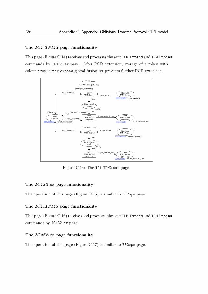
236 Appendix C. Appendix: Oblivious Transfer Protocol CPN model
The IC1 TPM2 page functionality
This page (Figure C.14) receives and processes the sent TPM Extend and TPM Unbind
commands by IC1S1 ex page. After PCR extension, storage of a token with
colour true in pcr extend global fusion set prevents further PCR extension.
IC1_TPM2 page
Bob Choice 1 (S1->S2)
vpcr_extended
vpcr_extended
vpcr_extended
1`true
1`tpm_unbind_res
1`next
1`next
vtmp_unbind
1`tpm_extend_res
1`next
1`next
vtpm_extend
Send TPM_UnBind
Response
Verify TPM_UnBind
[vpcr_extended]
Send TPM_Extend
Response
[not vpcr_extended]
Verify TPM_Extend
[not vpcr_extended]
PCR Extended
pcr_extend
1`false
csPCR_EXTENDED
sentTPM_Unbind
response
i_c1_msg4 csTPM_UNBIND_RES
send unbindresult
csSEQ
ReceivedTPM_Unbind
i_c1_msg3 csTPM_UNBIND
sentTPM_Extend
response
i_c1_msg2 csTPM_EXTEND_RES
send extendresult
csSEQ
ReceivedTPM_Extend
i_c1_msg1 csTPM_EXTENDi_c1_msg1
i_c1_msg2
i_c1_msg3
i_c1_msg4
pcr_extend
Figure C.14: The IC1 TPM2 sub-page
The IC1S2-ex page functionality
The operation of this page (Figure C.15) is similar to BS2opn page.
The IC1 TPM3 page functionality
This page (Figure C.16) receives and processes the sent TPM Extend and TPM Unbind
commands by IC1S2 ex page.
The IC2S2-ex page functionality
The operation of this page (Figure C.17) is similar to BS2opn page.

237
IC1S2_ex
Intruder Choice 1 (S1->S2): Extend PCR to open S2
verr
1`s1_s2_extended
1`fis2(s2)
1`next
1`next
1`endses
1`next
1`tpm_extend_args
vtpm_extend_res
1`next
1`tpm_unbind_args
1`next
vtpm_unbind_res
OpenS2
Send TPM_Extendto the TPM
Process TPM_Extend_Res
Send TPM_Unbindto the TPM
Process TPM_Unbind_Res
Bob_Intrudersecret 2
INT_DB
1`fipub_key1(pubk_k1)++1`fipub_key2(pubk_k2)
csINTDB
open secret2
csSEQ
errors andnotifications1
csERR
1`no_error
csERROR
Try to open Secret 2
IncsSEQ
SentTPM_Extend
i_c1_msg5csTPM_EXTEND
receivedTPM_Extend_Res
i_c1_msg6
csTPM_EXTEND_RES
sentTPM_Unbind
i_c1_msg7
csTPM_UNBIND
startunbind
csSEQ
end session
OutcsSEQ
receivedTPM_Unbind_Res
i_c1_msg8
csTPM_UNBIND_RES
i_c1_msg8
Out
i_c1_msg7
i_c1_msg6
i_c1_msg5 In
csERR
INT_DB
Figure C.15: The IC1S2 ex sub-page of page Extnd PCR
IC1_TPM3 page
Bob Choice 1 (S1->S2)
1`try_opening_s2
verr1`next
vpcr_extended
vtpm_extend
1`tpm_extend_res
1`next
1`next
1`tpm_unbind_res
1`next
vtmp_unbind
1`next
S2 can not be opened
[vpcr_extended]
Send TPM_Extend
Response
[not vpcr_extended]
Verify TPM_Extend
Send TPM_UnBind
Response
Verify TPM_UnBind
errors andnotifications1
csERR
1`no_error
csERROR
errors andnotifications2
csERR
1`no_error
csERROR
PCR Extended
pcr_extend
1`false
csPCR_EXTENDED
ReceivedTPM_Extend
i_c1_msg5 csTPM_EXTEND
sentTPM_Extend
response
i_c1_msg6 csTPM_EXTEND_RES
send extendresult
csSEQ
sentTPM_Unbind
response
i_c1_msg8 csTPM_UNBIND_RES
ReceivedTPM_Unbind
i_c1_msg7 csTPM_UNBIND
send unbindresult
csSEQ
i_c1_msg7
i_c1_msg8
i_c1_msg6
i_c1_msg5pcr_extend
csERR
csERR
Figure C.16: The IC1 TPM2 sub-page

238 Appendix C. Appendix: Oblivious Transfer Protocol CPN model
IC2S2_ex page
Intruder Choice 2 (S2->S1): Extend PCR to open S2
1`fis2(s2)
1`next
1`next
1`next
1`next
1`tpm_extend_args
vtpm_extend_res
1`next
1`tpm_unbind_args
1`next
vtpm_unbind_res
open secret 2
Send TPM_Extendto the TPM
Process TPM_Extend_Res
Send TPM_Unbindto the TPM
Process TPM_Unbind_Res
start openingsecret 2
csSEQ
Bob_Intrudersecret 2
INT_DB
1`fipub_key1(pubk_k1)++1`fipub_key2(pubk_k2)
csINTDB
Try to open Secret 2
IncsSEQ
SentTPM_Extend
i_c2_msg1 csTPM_EXTEND
receivedTPM_Extend_Res
i_c2_msg2csTPM_EXTEND_RES
sentTPM_Unbind
i_c2_msg3csTPM_UNBIND
startunbind
csSEQ
open secret2 and end
sessionOutcsSEQ
receivedTPM_Unbind_Res
i_c2_msg4csTPM_UNBIND_RES
i_c2_msg4
Out
i_c2_msg3
i_c2_msg2
i_c2_msg1In
INT_DB
Figure C.17: The IC2S2 ex sub-page of page Extnd PCR
The IC2 TPM2 page functionality
This page (Figure C.18) receives and processes the sent TPM Extend and TPM Unbind
commands by IC1S1 ex page. After PCR extension, storage of a token with
colour true in pcr extend global fusion set prevents further PCR extension.

239
IC2_TPM2 page
Bob Choice 2 (S2->S1)
vpcr_extended
vpcr_extended
vpcr_extended
1`true
vtpm_extend
1`tpm_extend_res
1`next
1`next
1`tpm_unbind_res
1`next
vtmp_unbind
1`next
Send TPM_Extend
Response
[not vpcr_extended]
Verify TPM_Extend
[not vpcr_extended]
Send TPM_UnBind
Response
Verify TPM_UnBind
[vpcr_extended]
PCR Extended
pcr_extend
1`false
csPCR_EXTENDED
ReceivedTPM_Extend
i_c2_msg1csTPM_EXTEND
sentTPM_Extend
responsei_c2_msg2 csTPM_EXTEND_RES
send extendresult
csSEQ
sentTPM_Unbind
responsei_c2_msg4 csTPM_UNBIND_RES
ReceivedTPM_Unbind
i_c2_msg3csTPM_UNBIND
send unbindresult
csSEQ
i_c2_msg3
i_c2_msg4
i_c2_msg2
i_c2_msg1
pcr_extend
Figure C.18: The IC2 TPM2 sub-page
The IC2S1 ex page functionality
The operation of this page (Figure C.19) is similar to BS1opn page.
The IC2 TPM3 page functionality
This page (Figure C.20) receives and processes the sent TPM Extend and TPM Unbind
commands by IC2S1 ex page.
The Dec Sec page functionality
This page (Figure C.21) demonstrates the Bob approach to decrypt secrets. After
receiving each secret, Bob as an intruder checks his database content to see
whether the corresponding private key for the encrypted secret is available or
not. If yes the secret will be decrypted and stored in the Bob database.
The decryptionkey(vpub key1)=vpri key1 and decryptionkey(vpub key2)=vpri key2
inscriptions of ‘Try to Decrypt Secret 1’ and ‘Try to Decrypt Secret 2’
transitions are used to check private key availability in the intruder database. If
the private key could be found then a s1 and s2 token will be stored in intruder

240 Appendix C. Appendix: Oblivious Transfer Protocol CPN model
IC2S1_ex Page
Intruder Choice 2 (S2->S1): Extend PCR to open S1
1`fis1(s1)
1`endses
1`s2_s1_extended
verr
1`next
1`next
1`next
1`tpm_extend_args
vtpm_extend_res
1`next
1`tpm_unbind_args
1`next
vtpm_unbind_res
OpenS1
Send TPM_Extendto the TPM
Process TPM_Extend_Res
Send TPM_Unbindto the TPM
Process TPM_Unbind_Res
Bob_Intrudersecret 1
INT_DB
1`fipub_key1(pubk_k1)++1`fipub_key2(pubk_k2)
csINTDB
Start Opening Secret 1
csSEQ
errors andnotifications1
csERR
1`no_error
csERROR
SentTPM_Extend
i_c2_msg5 csTPM_EXTEND
receivedTPM_Extend_Res
i_c2_msg6 csTPM_EXTEND_RES
sentTPM_Unbind
i_c2_msg7csTPM_UNBIND
startunbind
csSEQ
receivedTPM_Unbind_Res
i_c2_msg8 csTPM_UNBIND_RES
end session
OutcsSEQ
Try to open Secret 1
In csSEQIn
Out
i_c2_msg8
i_c2_msg7
i_c2_msg6
i_c2_msg5
csERR
INT_DB
Figure C.19: The IC2S1-ex sub-page of page Extnd-PCR
IC2_TPM3
Bob Choice 2 (S2->S1)
1`try_opening_s1
verr
1`next
vpcr_extended
vpcr_extended
vtpm_extend
1`tpm_extend_res
1`next
1`next
1`tpm_unbind_res
1`next
vtmp_unbind
1`next
S1 can not be opened
[vpcr_extended]
Send TPM_Extend
Response
[not vpcr_extended]
Verify TPM_Extend
Send TPM_UnBind
Response
Verify TPM_UnBind
errors andnotifications2
csERR
1`no_error
csERROR
errors andnotifications1
csERR
1`no_error
csERROR
PCR Extended
pcr_extend
1`false
csPCR_EXTENDED
ReceivedTPM_Extend
i_c2_msg5 csTPM_EXTEND
sentTPM_Extend
response
i_c2_msg6 csTPM_EXTEND_RES
send extendresult
csSEQ
sentTPM_Unbind
responsei_c2_msg8 csTPM_UNBIND_RES
ReceivedTPM_Unbind
i_c2_msg7csTPM_UNBIND
send unbindresult
csSEQ
i_c2_msg7
i_c2_msg8
i_c2_msg6
i_c2_msg5pcr_extend
csERR
csERR
Figure C.20: The IC2 TPM3 sub-page

241
database through ‘Bob Intruder secret 1’ and ‘Bob Intruder secret 2’
places. The decryptionkey() function code is shown in Figure C.22.
Dec_sec page
1`endses1`endses
1`next1`next
1`fis1(s1)
verr
1`s1_opened_by_dec
1`fis2(s2)
(vpub_key2, vsec2) verr
1`s2_opened_by_dec
fipri_key2(vpri_key2)fipri_key1(vpri_key1)
(vpub_key1, vsec1)
Try to DecryptSecret 2
[decryptionkey(vpub_key2)=vpri_key2]
Try to DecryptSecret 1
[decryptionkey(vpub_key1)=vpri_key1]
Bob_Intrudersecret 1
INT_DB
1`fipub_key1(pubk_k1)++1`fipub_key2(pubk_k2)
csINTDB
errors andnotifications1
csERR
1`no_error
csERROR
Bob_Intrudersecret 2
INT_DB
1`fipub_key1(pubk_k1)++1`fipub_key2(pubk_k2)
csINTDB
instance 2Encrypted Secret 2
ENC_S2csENC_S
errors andnotifications2
csERR
1`no_error
csERROR
intruderprivate
keysINT_DB
1`fipub_key1(pubk_k1)++1`fipub_key2(pubk_k2)
csINTDB
instance 2Encrypted Secret 1
ENC_S1csENC_S
start opening secrets by
decryptionIncsSEQ
end session
OutcsSEQ
Out
In
ENC_S1
INT_DB
csERR
ENC_S2
INT_DB
csERR
INT_DB
Figure C.21: The CPN model of Dec sec substitution transition in Main page
fun decryptionkey (key:csPUBKEY):csPRIKEY =
case key of pubk_k1 => prik_k1 |
pubk_k2 => prik_k2 |
_ => nopri_k;
Figure C.22: The detail of model functions
The sec err ex page functionality
The ‘Extract final error and Bob I knowledge’ substitution transition, is
the last transition of the Main page. Its main purpose is to collect a number
of tokens from different pages in Bob S1, Bob S2 and Errors places of the Main
page to verify the model. The verification will be performed using ASK-CTL
formula.
The sec err ex (Figure C.23) is the designed sub-page for this substitution
transition. The ‘Extract S1’, ‘Extract S2’ and error transitions extract S1,
S2 and error tokens from ‘Intruder S1’, ‘Intruder S2’ and ‘errors and notifica-

242 Appendix C. Appendix: Oblivious Transfer Protocol CPN model
tions1’ places then by storing them in ‘Bob S1’, ‘Bob S2’ and Errors output
ports send them to the Main page.
sec_err_ext page
1`next 1`next1`next
1`next1`next
1`next
vseq
vsec1 fis1(vsec1)
vseq
vsec2
fis2(vsec2)verrverr
Extract S1
Extract error, S1, S2
Extract S2error
Start error
csSEQ
start S1
csSEQ
start S2
csSEQ
Intruder S2
INT_DB
1`fipub_key1(pubk_k1)++1`fipub_key2(pubk_k2)
csINTDB
errors andnotifications1
csERR
1`no_error
csERROR
Intruder S1
INT_DB
1`fipub_key1(pubk_k1)++1`fipub_key2(pubk_k2)
csINTDB
Errors
Out
1`no_error
csERROR
Bob S1
OutcsSECRET
end session
OutcsSEQ
start extractingBob knowledge
IncsSEQ
Bob S2
OutcsSECRET
Out
In
Out
Out
Out
INT_DB
csERRINT_DB
Figure C.23: The CPN model of sec err ex page

Bibliography
[1] Security Frameworks for Open Systems. ITU-T Rec. X.810 - X.815,
November 1995.
[2] ISO/IEC 18033-2. : Information technology - Security techniques - En-
cryption algorithms - Part 2: Asymetric ciphers, 2006.
[3] ISO/IEC 18033-3. : Information technology - Security techniques - En-
cryption algorithms - Part 3: Block ciphers, 2005.
[4] ISO/IEC 19772. : Information technology - Security techniques - Authen-
ticated encryption, 2009.
[5] ISO/IEC 9797-2. Information technology - Security techniques - Messasge
Authenrication Codes (MACs) - Part 2: Mechanisms using a dedicated
hash-function, 2002.
[6] M. Abadi and B. Blanchet. Computer-assisted verification of a protocol
for certified email. Science of Computer Programming, 58(1-2):3–27, 2005.
[7] M. Abadi, B. Blanchet, and C. Fournet. Just fast keying in the pi calcu-
lus. ACM Transactions on Information and System Security (TISSEC),
10(3):9, 2007.
[8] M. Abadi, N. Glew, B. Horne, and B. Pinkas. Certified email with a light
on-line trusted third party: Design and implementation. In Proceedings of
the 11th international conference on World Wide Web, May, pages 07–11,
2002.
243

244 BIBLIOGRAPHY
[9] Martın Abadi and Phillip Rogaway. Reconciling Two Views of Cryptogra-
phy (The Computational Soundness of Formal Encryption). In IFIP TCS,
pages 3–22, 2000.
[10] W. Aiello, S.M. Bellovin, M. Blaze, R. Canetti, J. Ioannidis, A.D.
Keromytis, and O. Reingold. Just fast keying: Key agreement in a hostile
internet. ACM Transactions on Information and System Security (TIS-
SEC), 7(2):242–273, 2004.
[11] I. Al-Azzoni. The verification of cryptographic protocols using Coloured
Petri Nets. Master’s thesis, Department of Software Engineering, 2004.
[12] Issam Al-Azzoni, Douglas G. Down, and Ridha Khedri. Modeling and
Verification of Cryptographic Protocols Using Coloured Petri Nets and
design/cpn. Nord. J. Comput., 12(3):200–228, 2005.
[13] M.R. Albrecht, K.G. Paterson, and G.J. Watson. Plaintext recovery attacks
against SSH. In Security and Privacy, 2009 30th IEEE Symposium on,
pages 16–26. IEEE, 2009.
[14] S. Aly and K. Mustafa. Protocol verification and analysis using Colored
Petri Nets. Depaul University. July, July 2003.
[15] Myrto Arapinis, Stephanie Delaune, and Steve Kremer. From One Session
to Many: Dynamic Tags for Security Protocols. In LPAR, pages 128–142,
2008.
[16] Alessandro Armando, David A. Basin, Yohan Boichut, Yannick Cheva-
lier, Luca Compagna, Jorge Cuellar, Paul Hankes Drielsma, Pierre-Cyrille
Heam, Olga Kouchnarenko, Jacopo Mantovani, Sebastian Modersheim,
David von Oheimb, Michael Rusinowitch, Judson Santiago, Mathieu Tu-
ruani, Luca Vigano, and Laurent Vigneron. The AVISPA Tool for the
Automated Validation of Internet Security Protocols and Applications. In
CAV, pages 281–285, 2005.

BIBLIOGRAPHY 245
[17] Alessandro Armando, David A. Basin, Mehdi Bouallagui, Yannick Cheva-
lier, Luca Compagna, Sebastian Modersheim, Michael Rusinowitch, Math-
ieu Turuani, Luca Vigano, and Laurent Vigneron. The AVISS Security
Protocol Analysis Tool. In CAV, pages 349–353, 2002.
[18] M. Backes, C. Hritcu, and M. Maffei. Automated verification of remote
electronic voting protocols in the applied pi-calculus. In Computer Security
Foundations Symposium, 2008. CSF’08. IEEE 21st, pages 195–209. IEEE,
2008.
[19] Michael Backes, Stefan Lorenz, Matteo Maffei, and Kim Pecina. The
CASPA Tool: Causality-Based Abstraction for Security Protocol Analysis.
In Computer Aided Verification, pages 419–422. 2008.
[20] David A. Basin, Sebastian Modersheim, and Luca Vigano. OFMC: A
symbolic model checker for security protocols. Int. J. Inf. Sec., 4(3):181–
208, 2005.
[21] M. Bellare, R. Canetti, and H. Krawczyk. A modular approach to the
design and analysis of authentication and key exchange protocols. In Pro-
ceedings of the thirtieth annual ACM symposium on Theory of computing,
pages 419–428. ACM, 1998.
[22] K. Bhargavan, C. Fournet, and A. Gordon. Verified reference implementa-
tions of WS-Security protocols. Web Services and Formal Methods, pages
88–106, 2006.
[23] K. Bhargavan, C. Fournet, A.D. Gordon, and N. Swamy. Verified imple-
mentations of the information card federated identity-management proto-
col. In Proceedings of the 2008 ACM symposium on Information, computer
and communications security, pages 123–135. ACM, 2008.
[24] K. Bhargavan, C. Fournet, A.D. Gordon, and S. Tse. Verified interoperable
implementations of security protocols. ACM Transactions on Programming
Languages and Systems (TOPLAS), 31(1):5, 2008.

246 BIBLIOGRAPHY
[25] Matt Bishop. Computer Security: Art and Science. Addison-Wesley, Au-
gust 2003.
[26] B. Blanchet and A. Chaudhuri. Automated formal analysis of a protocol
for secure file sharing on untrusted storage. In Security and Privacy, 2008.
SP 2008. IEEE Symposium on, pages 417–431. IEEE, 2008.
[27] Bruno Blanchet. An Efficient Cryptographic Protocol Verifier Based on
Prolog Rules. In CSFW, number 0-7695-1146-5, pages 82–96. IEEE Com-
puter Society, 2001.
[28] Bruno Blanchet. A Computationally Sound Mechanized Prover for Security
Protocols. In IEEE Symposium on Security and Privacy, pages 140–154,
2006.
[29] Bruno Blanchet. A Computationally Sound Mechanized Prover for Security
Protocols. IEEE Trans. Dependable Sec. Comput., 5(4):193–207, 2008.
[30] L. Bozga, Y. Lakhnech, and M. Perin. Hermes: An automatic tool for
verification of secrecy in security protocols. In Computer Aided Verification,
pages 219–222. Springer, 2003.
[31] S.H. Brackin. A HOL extension of GNY for automatically analyzing cryp-
tographic protocols. In Computer Security Foundations Workshop, 1996.
Proceedings., 9th IEEE, pages 62–76. IEEE, 1996.
[32] Danilo Bruschi, Lorenzo Cavallaro, Andrea Lanzi, and Mattia Monga. Re-
play Attack in TCG Specification and Solution. In ACSAC, pages 127–137,
2005.
[33] Michael Burrows, Martin Abadi, and Roger Needham. A logic of authen-
tication. ACM Trans. Comput. Syst., 8(1):18–36, 1990.
[34] D. Challener, K. Yoder, R. Catherman, D. Stafford, and L. V. Doorn. A
Practical Guide to Trusted Computing. IBM Press, 1st edition, December
2007.

BIBLIOGRAPHY 247
[35] L. Chen and M. Ryan. Offline dictionary attack on TCG TPM weak autho-
risation data, and solution. Future of Trust in Computing, pages 193–196,
2009.
[36] L. Chen and M. Ryan. Attack, solution and verification for shared autho-
risation data in TCG TPM. Formal Aspects in Security and Trust, pages
201–216, 2010.
[37] Q. Chen, C. Zhang, and S. Zhang. Overview of security protocol analysis.
Secure Transaction Protocol Analysis, pages 17–72, 2008.
[38] A. Cheng, S. Christensen, and K.H. Mortensen. Model checking Coloured
Petri Nets exploiting strongly connected components. Citeseer, 1997.
[39] S. Christensen and K.H. Mortensen. Design/CPN ASK-CTL Manual,
1996.
[40] E.M. Clarke, E.A. Emerson, and A.P. Sistla. Automatic verification
of finite-state concurrent systems using temporal logic specifications.
ACM Transactions on Programming Languages and Systems (TOPLAS),
8(2):244–263, 1986.
[41] E.M. Clarke, S. Jha, and W. Marrero. Verifying security protocols with
Brutus. ACM Transactions on Software Engineering and Methodology
(TOSEM), 9(4):443–487, 2000.
[42] V. Cortier. A guide for Securify, 2003.
[43] C. Cremers. Feasibility of multi-protocol attacks. In Availability, Reliability
and Security, 2006. ARES 2006. The First International Conference on,
page 8 pp., 2006.
[44] C. Cremers. The Scyther Tool: Verification, falsification, and analysis of se-
curity protocols. In Computer Aided Verification, pages 414–418. Springer,
2008.

248 BIBLIOGRAPHY
[45] Cas. Cremers and P. Lafourcade. Comparing State Spaces in Automatic
Security Protocol Verification. In 7th International Workshop on Auto-
mated Verication of Critical Systems (AVoCS). Elsevier Science Publishers
B. V., 2007.
[46] C.J.F. Cremers. Scyther: Semantics and verification of security protocols,
2006.
[47] C. Crepeau. Equivalence between two flavours of oblivious transfers. In
Advances in CryptologyCRYPTO87, pages 350–354. Springer, 2006.
[48] L Davi, AR Sadeghi, and M Winandy. Dynamic integrity measurement and
attestation: towards defense against return-oriented programming attacks.
pages 49–54. ACM, 2009.
[49] S. Delaune, S. Kremer, and M. Ryan. Verifying privacy-type properties of
electronic voting protocols. Journal of Computer Security, 17(4):435–487,
2009.
[50] S. Delaune, M. Ryan, and B. Smyth. Automatic verification of privacy
properties in the applied pi calculus. Trust Management II, pages 263–
278, 2008.
[51] Stephanie Delaune, Steve Kremer, Mark Dermot Ryan, and Graham Steel.
Formal Analysis of Protocols Based on TPM State Registers. In CSF,
pages 66–80, 2011.
[52] M. Diaz. Petri Nets: Fundamental models, verification and applications.
Wiley-ISTE, 2010.
[53] W. Diffie, P.C. Oorschot, and M.J. Wiener. Authentication and authen-
ticated key exchanges. Designs, Codes and Cryptography, 2(2):107–125,
1992.
[54] E.M. Doyle, S. Tavares, and H. Meijer. Automated security analysis of
cryptographic protocols using Coloured Petri Net specifications. Master’s
thesis, Queen' s University at Kingston, 1997.

BIBLIOGRAPHY 249
[55] Luca Durante, Riccardo Sisto, and Adriano Valenzano. Automatic testing
equivalence verification of spi calculus specifications. ACM Trans. Softw.
Eng. Methodol., 12(2):222–284, 2003.
[56] B. Dutertre and S. Schneider. Using a PVS embedding of CSP to verify
authentication protocols. Theorem Proving in Higher Order Logics, pages
121–136, 1997.
[57] S. Escobar, C. Meadows, and J. Meseguer. Maude-NPA: Cryptographic
protocol analysis modulo equational properties. Foundations of Security
Analysis and Design V, pages 1–50, 2009.
[58] S. Even, O. Goldreich, and A. Lempel. A randomized protocol for signing
contracts. Communications of the ACM, 28(6):637–647, 1985.
[59] B. Fontan, S. Mota, T. Villemur, P. Saqui-Sannes, and J.P. Courtiat. UML-
based modeling and formal verification of authentication protocols. 2006.
[60] Lowe Gavin. Casper: A compiler for the analysis of security protocols.
Journal of Computer Security, 6(1):53–84, 1998.
[61] L. Gong, R. Needham, and R. Yahalom. Reasoning about Belief in Cryp-
tographic Protocols. 1990.
[62] D. Grawrock. TCG Specification Architecture Overview Revision 1. 4, 2nd
August 2007.
[63] Sigrid Gurgens, Carsten Rudolph, Dirk Scheuermann, Marion Atts, and
Rainer Plaga. Security Evaluation of Scenarios Based on the TCG’s TPM
Specification. In ESORICS, pages 438–453, 2007.
[64] G. Hollestelle and S. Mauw. Systematic analysis of attacks on security
protocols. Master’s Thesis, Technical University of Eindhover, Department
of Mathematics and Computer Science, 2005.
[65] David P. Jablon. Extended Password Key Exchange Protocols Immune to
Dictionary Attacks. In WETICE, pages 248–255, 1997.

250 BIBLIOGRAPHY
[66] DP Jablon. Strong password-only authenticated key exchange. ACM SIG-
COMM Computer Communication Review, 26(5):26, 1996.
[67] K. Jensen. Coloured Petri Nets. Basic Concepts, Analysis Methods and
Practical Use. Basic Concepts. Springer, Berlin, vol. 1., 1992.
[68] K. Jensen. Coloured Petri Nets. Basic Concepts, Analysis Methods and
Practical Use. Analysis Methods. Springer, Berlin, vol. 2, 1994.
[69] K. Jensen. A brief introduction to Coloured Petri Nets. Tools and Algo-
rithms for the Construction and Analysis of Systems, pages 203–208, 1997.
[70] K. Jensen. Coloured Petri Nets. Basic Concepts, Analysis Methods and
Practical Use, volume Volume 1, Basic Concepts. Monographs in Theo-
retical Computer Science. Berlin, Heidelberg, New York: Springer-Verlag,
2nd corrected printing 1997, ISBN: 3-540-60943-1, 1997.
[71] K. Jensen. Coloured Petri Nets. Basic Concepts, Analysis Methods and
Practical Use., volume Volume 2, Analysis Methods. Monographs in Theo-
retical Computer Science. Berlin, Heidelberg, New York: Springer-Verlag,
2nd corrected printing 1997, ISBN: 3-540-58276-2, 1997.
[72] K. Jensen. Coloured Petri Nets. Basic Concepts, Analysis Methods and
Practical Use. Practical use. Springer, Berlin, vol. 3, 1997.
[73] K. Jensen. An Introduction to the Practical Use of Coloured Petri Nets.
In In: Reisig, W., Rozenberg, G. (eds.): Lectures on Petri nets II. LNCS
1492., pages 237–292. Berlin, Heidelberg, New York: Springer Verlag,,
1998.
[74] K Jensen. Special section on Coloured Petri Nets. International Journal
on Software Tools for Technology Transfer (STTT), 9(3):209–212, 2007.
[75] K. Jensen, L.M. Kristensen, and L. Wells. Coloured Petri Nets and CPN
Tools for modelling and validation of concurrent systems. International
Journal on Software Tools for Technology Transfer (STTT), 9(3):213–254,
2007.

BIBLIOGRAPHY 251
[76] Kurt Jensen. How to Find Invariants for Coloured Petri Nets. In MFCS,
pages 327–338, 1981.
[77] M. Kallahalla, E. Riedel, R. Swaminathan, Q. Wang, and K. Fu. Plutus:
Scalable secure file sharing on untrusted storage. In Proceedings of the 2nd
USENIX Conference on File and Storage Technologies, pages 29–42, 2003.
[78] B. Kauer. OSLO: Improving the security of Trusted Computing. In Pro-
ceedings of 16th USENIX security symposium on usenix security sympo-
sium, page 16. USENIX Association, 2007.
[79] S. Kremer and M. Ryan. Analysis of an electronic voting protocol in the
applied pi calculus. Programming Languages and Systems, pages 140–140,
2005.
[80] K Kursawe, D Schellekens, and B Preneel. Analyzing trusted platform
communication. Citeseer, 2005.
[81] M. Kwiatkowska, G. Norman, and D. Parker. PRISM 2.0: A tool for
probabilistic model checking. In Quantitative Evaluation of Systems, 2004.
QEST 2004. Proceedings. First International Conference on the, pages 322–
323. IEEE, 2004.
[82] Hugo Andres Lopez. Frameworks for the Analysis of Security Protocols, A
Survey. Technical report, September 2006.
[83] G. Lowe. An attack on the Needham-Schroeder public-key authentication
protocol. Information processing letters, 56(3):131–133, 1995.
[84] G. Lowe. Casper: A compiler for the analysis of security protocols. In
Computer Security Foundations Workshop, 1997. Proceedings., 10th, pages
18–30. IEEE, 2002.
[85] Gavin Lowe. Breaking and Fixing the Needham-Schroeder Public-Key
Protocol Using FDR. Software - Concepts and Tools, 17(3):93–102, 1996.
[86] Gavin Lowe. Towards a Completeness Result for Model Checking of Secu-
rity Protocols. In CSFW, pages 96–105, 1998.
252 BIBLIOGRAPHY
[87] Paolo Maggi and Riccardo Sisto. Using SPIN to Verify Security Properties
of Cryptographic Protocols. In SPIN, pages 187–204, 2002.
[88] C. Meadows. Formal methods for cryptographic protocol analysis: emerg-
ing issues and trends. Selected Areas in Communications, IEEE Journal
on, 21(1):44–54, 2003.
[89] C. Meadows and C. Meadows. Formal verification of cryptographic pro-
tocols: A survey. Advances in CryptologyASIACRYPT’94, pages 133–150,
1995.
[90] Catherine Meadows. A System for the Specification and Verification of
Key Management Protocols. In IEEE Symposium on Security and Privacy,
pages 182–197, 1991.
[91] Catherine Meadows. Language generation and verification in the NRL
protocol analyzer. In CSFW, pages 48–61, 1996.
[92] Catherine Meadows. The NRL Protocol Analyzer: An Overview. J. Log.
Program., 26(2):113–131, 1996.
[93] J. K. Millen, S. C. Clark, and S. B. Freedman. The Interrogator: Proto-
col Secuity Analysis. Software Engineering, IEEE Transactions on, SE-
13(2):274–288, 1987.
[94] C. Mitchell. Trusted computing, volume 6. Iet, 2005.
[95] R.M. Needham and M.D. Schroeder. Using encryption for authentication
in large networks of computers. Communications of the ACM, 21(12):999,
1978.
[96] O.K Olsen. Adversary modelling. Master’s thesis, Department of Computer
Science and Media Technology, Gjvik University College,, 2005.
[97] S Owre, J Rushby, and N Shankar. PVS: A prototype verification system.
Automated DeductionCADE-11, pages 748–752, 1992.

BIBLIOGRAPHY 253
[98] R. Patel, B. Borisaniya, A. Patel, D. Patel, M. Rajarajan, and A. Zisman.
Comparative Analysis of Formal Model Checking Tools for Security Pro-
tocol Verification. In Recent Trends in Network Security and Applications:
Third International Conference, CNSA 2010, Chennai, India, July 23-25,
2010 Proceedings, volume 89, page 152. Springer, 2010.
[99] L.C. Paulson. Isabelle: A generic theorem prover. Springer, 1994.
[100] C. A. Petri. Fundamentals of a Theory of Asynchronous Information Flow.
In IFIP Congress, pages 386–390, 1962.
[101] A. Pironti, D. Pozza, and R. Sisto. Automated Formal Methods for Security
Protocol Engineering. Cyber Security Standards, Practices and Industrial
Applications: Systems and Methodologies, page 138, 2011.
[102] M.O. Rabin. How to exchange secrets by oblivious transfer. Technical
report, Technical Report TR-81, Harvard Aiken Computation Laboratory,
1981.
[103] Anne V. Ratzer, Lisa Wells, Henry Michael Lassen, Mads Laursen, Ja-
cob Frank Qvortrup, Martin Stig Stissing, Michael Westergaard, Søren
Christensen, and Kurt Jensen. CPN tools for Editing, Simulating, and
Analysing Coloured Petri Nets. In ICATPN, pages 450–462, 2003.
[104] J Repp, R Rieke, and F Publica. Simple Homomorphism Verification Tool
(SHVT)-Manual, 2004.
[105] A.D. Rubin and P. Honeyman. Formal methods for the analysis of authen-
tication protocols. Technical report, Citeseer, 1993.
[106] Ahmad-Reza Sadeghi, Marcel Selhorst, Christian Stuble, Christian Wachs-
mann, and Marcel Winandy. TCG inside?: a note on TPM specification
compliance. In STC, pages 47–56, 2006.
[107] S. Schneider. Verifying authentication protocols in CSP. Software Engi-
neering, IEEE Transactions on, 24(9):741–758, 1998.

254 BIBLIOGRAPHY
[108] S. Schneider and R. Holloway. Modelling security properties with CSP.
Citeseer, 1996.
[109] Y. Seifi, S. Suriadi, E. Foo, and C. Boyd. Analysis of Object-Specific
Authorization Protocol (OSAP) using Coloured Petri Nets - Version 1.0.
Technical report, Queensland University of Technology, June 2011.
[110] Y. Seifi, S. Suriadi, E. Foo, and C. Boyd. Analysis of Object-Specific
Authorization Protocol (OSAP) using Coloured Petri Net. In AISC2012
proceedings, January 2012.
[111] P. E. Sevinc, M. Strasser, and D. Basin. Securing the Distribution and
Storage of Secrets with Trusted Platform Modules. WISTP2007, pages
53–66, 2007.
[112] C.E. Shannon, W. Weaver, R.E. Blahut, and B. Hajek. The mathematical
theory of communication, volume 117. University of Illinois press Urbana,
1949.
[113] Dawn Xiaodong Song. Athena: A New Efficient Automatic Checker for
Security Protocol Analysis. In CSFW, pages 192–202, 1999.
[114] E Sparks. A security assessment of trusted platform modules. Computer
science technical report. http://www. ists. dartmouth. edu/library/341. pdf,
June , 2007.
[115] A. Tarigan et al. Survey in Formal Analysis of Security Properties of
Cryptographic Protocol. Universitat Bielefeld, 2002.
[116] TCG. TCG specification Architecture Overview Revision 1.4, August 2007.
[117] TCG. Replacing Vulnerable Software with Secure Hardware: The Trusted
Platform Module (TPM) and How to Use It in the Enterprise, 2008.
[118] TCG. Enterprise Security: Putting the TPM to Work, September 2005.
[119] OpenSSL Team. OpenSSL Security Advisor, 2009.

BIBLIOGRAPHY 255
[120] R. Toegl, G. Hofferek, K. Greimel, A. Leung, R. C. W. Phan, and R. Bloem.
Formal Analysis of a TPM-Based Secrets Distribution and Storage Scheme.
In Young Computer Scientists, 2008. ICYCS 2008. The 9th International
Conference for, pages 2289–2294, 2008.
[121] Gergely Toth, Gabor Koszegi, and Zoltan Hornak. Case study: automated
security testing on the trusted computing platform. In EUROSEC, pages
35–39, 2008.
[122] Luca Vigano. Automated Security Protocol Analysis With the AVISPA
Tool. Electr. Notes Theor. Comput. Sci., 155:61–86, 2006.
[123] M. Westergaard, S. Evangelista, and L. Kristensen. ASAP: An Extensible
Platform for State Space Analysis. Applications and Theory of Petri Nets,
pages 303–312, 2009.
[124] T.Y.C. Woo and S.S. Lam. A semantic model for authentication proto-
cols. In Research in Security and Privacy, 1993. Proceedings., 1993 IEEE
Computer Society Symposium on, pages 178–194. IEEE, 1993.
[125] T.Y.C. Woo and S.S. Lam. Verifying authentication protocols: Methodol-
ogy and example. In Network Protocols, 1993. Proceedings., 1993 Interna-
tional Conference on, pages 36–45. IEEE, 1993.
[126] A. Yao. On the security of public key protocols. IEEE Transactions on
Information Theory, 29(2):198–208, 1983.

Index
AACP, 38, 40
ABP, 18
ADCP, 38, 40
ADIP, 38, 39
AIK, 33, 34, 37
API, 36, 42
Arc, 22
Arc inscription, 22
ASK-CTL, 28
authData, 34, 37, 43
Authorisation, 35
AVISPA, 15
BAN, 13
BGNY, 14
Binding, 22
Binding elements, 22
BIOS, 41
Brutus, 14
CC, 33
Colour set, 22
configurability, 117
CPN/Tools, 22
CRTM, 31, 32
CryptoVerif, 16
CTL, 21, 27
EK, 34
Enabler place, 78
Error-Discovery, 102
EVA, 17
Fusion set, 23
GNY, 14
Guards, 22
GUI, 23
Hermes, 17
HMAC, 47
I/O port, 23
Input socket, 23
Interrogator, 15
ITU, 8
LTL, 22
Marking, 22
ML, 22
NPA, 13
NSPK, 29, 52
NuSMV, 45
OG, 27
OIAP, 38
OSAP, 38, 39
OT, 127
256

INDEX 257
Output socket, 23
parameterisation, 101
PCA, 134
PCR, 32–34
Place, 22
PNO, 29
Proverif, 16
RTM, 31
RTR, 31
RTS, 31
SCC, 27
SCC-graph, 27
Scyther, 16
SHVT, 17
SKAP, 48
SML, 22
Socket, 23
SPEKE, 43
SRK, 34, 47
srkAuth, 48
STS, 29
TC, 30
TCG, 30
TCS, 38, 46
TDDL, 41
TLS, 38
Token, 22
TPM, 33
tpm-related-security-property, 127
Transition, 22
TSS, 41, 42