forced-convection h eat-transfer measurements...
TRANSCRIPT
ORNL-TM-4079
3 0
FORCED-CONVECTION H EAT-TRANSFER MEASUREMENTS WITH
A MOLTEN FLUORIDE SALT MIXTURE FLOWING IN A SMOOTH TUBE
J. W . Cooke
B. c o x

This report was prepared as an account of work sponsored by the United States Government. Neither the United States nor the United States Atomic Energy Commission, nor any of their employees, nor any of their contractors, subcontractors, or their employees, makes any warranty, express or implied, or assumes any legal liability or responsibility for the accuracy, completeness or usefulness of any information, apparatus, product or process disclosed, or represents that i t s use would not infringe privately owned rights.

W
Contract NO. W-7405-eng-26
/
Reactor Division
MARCH 1973
OAK RIDGE NATIONAL LABORATORY Oak Ridge, Tennessee 37830
UNION CARBIDE CORPORATION for the
U. S. ATOMIC ENERGY COMMISSION
operated by .


iii
W c;
coNTms - Page
Abstract.. . . . . . . . . . . . . . . . . . . . . . . . . . . . . 1
Introduction . . . . . . . . . . . . . . . . . . . . . . . . . . . . 1
Description of the Apparatus . . . . . . . . . . . . . . . . . . . . 2
Operating Procedures . . . . . . . . . . . . . . . . . . . . . . . . 11
Calculations . . . . . . . . . . . . . . . . . . . . . . . . . . . . 1 5
Results . . . . . . . . . . . . . . . . . . . . . . . . . . . . . . 16
Discussion . . . . . . . . . . . . . . . . . . . . . . . . . . . . . . 24
Conclusions . . . . . . . . . . . . . . . . . . . . . . . . . . . . 27
Acknowledgments . . . . . . . . . . . . . . . . . . . . . . . . . . 27
References . . . . . . . . . . . . . . . . . . . . . . . . . . . . . 27 f
t
.c ’ .
Appendix A -Additional Details of the Experimental System . . . . . 29
Appendix B - Experimental Data . . . . . . . . . . . . . . . . . . . 37
Appendix C -Computer Program . . . . . . . . . . . . . . . . . . . 43 Appendix D - Chemical Analyses and Physical Properties of the Salt . 55

t

bi n
FORCED-CONVECTION HEAT-TRANSFER MEASUREMENTS WITH A MOLTEN FLUORIDE SALT MIXTURE FLOWING IN A SMOOTH TUBE
J. W. Cooke B. Cox
ABSTRACT
Heat-transfer coeff ic ients were determined experimentally f o r a proposed MSBR f u e l salt (LiF-BeF,-ThF4-UF4;67.5-20.0-12 .O-0.5 mole 4 ) flowing by forced convection through a 0.18-in.-n> hori- zontal, c i r cu la r tube f o r the following range of variables:
Reynolds modulus 400 - 30,600 Prandtl modulus 4 - 14 Average f l u i d temperature (OF)
Heat f lux (Btu/hr f t2 ) 1050 - 1550 22,000 - 560,000
Within these ranges, the heat-transfer coeff ic ient was found t o vary from 320 up t o 6900 Btu/hr*ft2 OF (Nusselt modulus of 6.5 t o 138). equations :
Correlations of the experimental data resul ted i n the
w i t h
w i t h and
with
heat
an average absolute deviation of 6.g for NRe < 1000;
an average absolute deviation of 4.1$ f o r 3500 < NRe < 12,000;
an average absolute deviation of 6.2$ f o r NRe > 12,000.
Keywords: Heat t ransfer , fused salts, forced convection, exchangers, f l u i d flow, correlat ions.
INTRODUCTION
The design of molten salt reactors requires detailed informt ion about the t ransport properties of the proposed fuel , coolant and blanket
mixtures. Although the molten salts generally behave as normal f lu ids
w i t h respect t o heat transfer,' the poss ib i l i t y of unexpected e f fec ts ,
1

2
LI such as nonwetting of metallic surfaces or the formation of low-conductance surface f i l m s , indicates that heat-transfer measurements for specif ic re- c
actor salts are needed.=
w i t h a proposed reactor f u e l of mixed fluoride salts (LiF-BeFsThF4-UF4;
67.5-20.0-12.0-0.5 mole 8 ) . The technique employs forced convection of
the l iquid salts through a smooth thin-walled Hastelloy N tube.
ance heating supplies the tube w i t h a uniform heat flux.
par t icular ly well suited t o the molten sal t system because the e l ec t r i ca l
resistance of the molten salt is very large compared with t h a t of the metal tube.
constant over the en t i r e temperature range of the measurements, which
simplifies the achievement of an ax ia l ly uniform heat flux. a constant heat capacity of the molten salt i n the observed temperature
range mkes possible several convenient assumptions i n the calculation of local f lu id bulk temperatures.
This report describes heat-transfer experiments
e
Resist-
This method i s
Furthermore, the resistance of Hastelloy N remains nearly
In addition,
DESCRIPTION OF THE APPARATUS
The apparatus fo r studying heat t ransfer with the molten salt system is shown schetmtically i n Fig. 1 and i n the photograph, Fig. 2. Molten salt flows by means of gas pressure through a small diameter, e l ec t r i ca l ly
heated tes t section. The f l o w of molten salt alternates i n direct ion as
pressure from an ine r t gas supply is added t o e i the r of two storage ves- sels located a t each end of the t e s t channel. Each 6-ga1. salt reservoir
is suspended from a weigh c e l l whose recorded s ignal indicates the flow
rate.
valves that control the flow of i ne r t gas t o the reservoirs.
The flow of salt reverses au tomt ica l ly by the act ion of solenoid
The r a t e of
flow of the salt m y be varied from 0.25 t o 1.7 gal/min, emptying a
reservoir i n from 3 t o 20 minutes.
The weigh ce l l c i r c u i t shown i n Fig. 3 i l l u s t r a t e s t he e l ec t r i ca l
and mechanical systems tha t control the flow of gas and thereby the flow
of molten salt .
section, t o prevent it from sagging, by means of counter weights connected
by f lex ib le cables.
A second suspension system maintains tension on the t e s t
The t e s t section consists of a smooth Hastelloy N
tube, 24.5 in. long, O.25-in. outside diameter, and 0.035-in.-wall

r REVERSE FLOW CONNECTING TUBING
.
ir
1
I
I 1 1 1 1
1 1 i 1 (It2 _ .-_. L.
\ MIXING CHAMBER
*SALT TANK SALT TANK -
ORNL-OWG 66-42942
ARGON
VALVE
E- ELECTRIC HEATERS
W
Fig. 1. Schematic diagram for determining the heat-transfer characteristics of molten salt by forced convection.

4
Fig. 2. as that of Fig. 1.
Photograph of the apparatus viewed from the same aspect

c
MECHANICAL /EL;--
HONEYWELL RECORDER CONTROL
I 1 i I
ORNL-DWG 72- 4 4510
------ 1 I I
SOLENOID VALVE -
GAS ‘t
TANK
,,4
-
Fig. 3. Weigh cell circuit for molten salt heat-transfer system.

b
thickness and is resistance heated with a 60 Hz ac power supply.
d e t a i l of the mixing chambers located at each end of the t e s t sect ion is shown i n Fig. A-1, Appendix A .
with the power c i r c u i t serve a l so as end plates of the disk-and-donut
mixing chambers. The e l ec t r i ca l power t o the t e s t sect ion is supplied by a 440/25 v, 25 kva
transformer and is measured with a General Elec t r ic watt transducer, a l s o
shown i n Fig. 4. of vermiculite powder contained i n a sheet metal t ray .
and connecting tubes a re heated by auxi l iary clamshell and Calrod heaters
placed i n positions indicated i n Fig. 1. A typ ica l thea te r c i r c u i t f o r an
auxi l iary heater is depicted i n Fig. 5 .
A
The electrodes connecting the t e s t section
The power c i r c u i t t o the t e s t sect ion is shown i n Fig. 4.
The t e s t sect ion is insulated with a 3-in.-thick layer The salt reservoirs
The i n l e t and out le t salt temperatures a re measured by four, 40-mil- diam, Chromel-Alumel sheathed thermocouples inserted in to two wells i n each mixing chamber (Fig. Arl). The temperature d is t r ibu t ion along the
t e s t sect ion is measured by a se r i e s of 24 Chromel-Alumel thermocouples (0.005-in.-diam wire) spot welded a t 1-in. intervals t o the outside tube
w a l l . The scheme f o r attaching these thermocouples is shown i n Fig. A-2.
Details of a salt reservoir can be seen i n Fig. A-3. The in t e r io r
of these tanks as well as the t e s t sect ion and the mixing chanibers a re
s t r e s s relieved and hydrogen f i r e d before they a re assembled. A data acquis i t ion system provides fo r t h e a u t o m t i c monitoring of
the temperatures; record is mde ,by a paper printout and a paper tape punch. In t h i s system a multichannel Vidar data recorder reads emf signals from each thermocouple, from the weigh c e l l s , and from the power
c i r c u i t i n a sequential switching arrangement known as a "crossbar
scanner."
fo r the Vidar system.
i n Fig. 6 and i n a photograph i n Fig. 7.
The manufacturer claims an accuracy of b e t t e r than +O.5"F The data recording equipment is shown schematically
The weigh c e l l and wattmeter ca l ibra t ion curves and a l i s t of per-
t inent experimental equipment may be found i n Appendix A as Fig. A-4, Fig. A-5, and Table A-1, respectively.
L)

. .. . . .. .- *-
ORNL-DWG 72-ttstt
# . 7 PANELBOARO POTENTIAL FRAME GROUND
POWER TRANSFORMER TRANSFORMER I 1 .. r-,-T- "
SIGNAL TO VIDAR
- - WATTMETER
TEST SECTION FRAME GROUND
4
Fig. 4. Test-section power c i r c u i t f o r molten salt heat-transfer experiment.

8
NEUTRAL
W .
HOT
EVl= VOLTMETER E i I=AMMETER
ORNL-DWG 72-1 4542 POWER CIRCUIT
145 V AC
E i I o-'50v @ O - I O A , ,~ @- - -< :XF:MENT
f TEMPERATURE
I I
-- -- RELAY I CONTROLLER

9
SEQUENTIAL - .
TAPE PUNCH
.1 .
ORNL-DWG 72-14543
t VIDAR DIGITAL
VOLTMETER
TE REF. JUNCTION
Q Fig. 6. Thermocouple c i r c u i t f o r molten salt heat-transfer system.

Fig. 7. Photograph of data recording equipment.
c , I a

U - . .
.
hd I
I
I n preparation fo r the addition of the molten salt mixtures, the system including the t e s t sect ion is heated t o the desired temperature leve l above the melting point of the salt mixture.
of the molten salt is then introduced in to one of the reservoirs by the
force of argon gas pressure. Salt is forced back and f o r t h through the t e s t sect ion as the operation of the apparatus is tes ted - fo r leaks, blockages, thermocouple and data recording functioning, e tc .
i n i t i a l checkout procedure, the system is put on a standby mode by vent- ing the gas pressure t o the atmosphere and allowing the salt t o siphon t o
equal levels i n both reservoirs.
tes t -sect ion thermocouples by minimizing the heating of the t e s t section.
Approximately 165 l b
After the
* The standby mode is used t o protect the
Before each run, temperatures i n the t e s t section a r e ra ised t o about
lOOOOF over a period of 45 minutes and the salt flow is reestablished. A
fixed flow r a t e is established and power t o the tes t -sect ion heater is in-
creased t o the desired heat f lux.
s t a t e conditions, a l l parameters - power input, flow ra te , and tempera-
tures - are continuously recorded,
reservoir is nearly empty, and the heat f lux is momentarily reduced t o
about half the operating value t o prevent a temperature excursion i n the
t e s t sect ion a t the time of zero flow. The upper range of f l a w ra tes is
l imited by the time required t o empty one of the reservoirs. the temperature exceeds the desired level , the system is allowed to cool
by reducing the power t o the t e s t sect ion and other appropriate heaters.
When the temperatures indicate steady-
The flow of salt i s reversed when one
Whenever
Periodic cal ibrat ions of radial heat losses were made by measuring the power required t o m i n t a i n an empty t e s t sect ion i n an isothermal condition as a function of temperature leve l . The information furnished
by t h i s ca l ibra t ion is used i n each run, when an isothermal check of the tes t -sect ion thermocouples is obtained a t the desired temperature leve l
* This procedure resul ted i n several salt leaks when a number of power
f a i lu re s occurred during the standby condition. Melting of the confined salt was invariably accompanied by rupture of the thin-walled tubing due t o the expansion of the salt upon p a r t i a l melting. cedure would be t o drain the salt in to one reservoir, allowing unrestrained expansion of the salt during melting if an unexpected freeze should occur.
A be t t e r standby pro-

12
wi th the hot salt flowing and only enough heat added t o the t e s t sect ion
t o equal the radial heat loss.
couple readings from an i so therm1 run show a scatter band of f4'F about
the average outside w a l l temperature. The sheathed thermocouples i n the mixing chambers read s l i g h t l y higher during isothermal runs and a r e be-
lieved t o be more accurate.
fo r standardization and the tube wall readings a r e corrected t o t h i s standard .
In Fig. 8, typ ica l tes t - sec t ion thermo-
Their readings, therefore, provide the basis
Extensive t e s t s were conducted t o insure the r e l i a b i l i t y of the
apparatus and experimental procedures. The first tes t -sect ion tube pro- duced e r r a t i c a x i a l temperature patterns which d i d not improve w i t h more
thermal insulation of the t e s t section.
temperature prof i les were traced t o the t e s t section, i n which a hole had
burned through the w a l l and had been repaired by welding. Excessive weld material protruding in to the tube was thought t o have disturbed the tem-
perature and velocity prof i les .
the d i f f i cu l ty .
Subsequently, the anomalous ax ia l
Replacement of the t e s t sect ion eliminated
Other possible sources of e r ror were investigated during t h e search f o r the cause of the temperature i r r egu la r i t i e s . E lec t r ica l conduction
through the molten salt would r e s u l t i n addi t ional heating of the salt,
but the r a t i o of the r e s i s t i v i t y of the salt t o that of the t e s t sect ion
is greater than 2500, indicating very l i t t l e heat generated i n the salt i n
t h i s manner. Additional calculations of the radial temperature d i s t r i -
bution4 confirmed that not more than 0.2$ of the power was expended by
e l e c t r i c a l conduction i n the salt. Temperature var ia t ions due t o f r ee convection a r e believed t o be
la rger than those a t t r ibu tab le t o in te rna l heating; but according t o the
c r i t e r ion of Shannon and DePew,' f r ee convection i n the horizontal t e s t -
section posit ion is insignificant compared with forced convection i n the range of Reynolds numbers described i n t h i s work.
A s an addi t ional check of natural-convection effects , the reactor f u e l salt experiments were repeated w i t h the t e s t sect ion anchored i n a
ve r t i ca l posit ion while other equipment arrangements and operational pro-
cedures remained unchanged.
e f fec ts of f r ee convection i n the ve r t i ca l and horizontal posit ions.
The object of the change was t o compare the A
W

om DWG 6g-ncj28
X, dietance from Inlet (in.)
Fig. 8. Tube wall thermocouple readings during isothermal salt flow.

14
crack developed i n one of t h e piping connections t o the tes t sect ion a f t e r 8 runs and repairs were not attempted.
the v e r t i c a l runs d id not show any difference i n the e f f ec t of f r e e con- vection as related t o the or ientat ion of the tes t section. The data are presented l a t e r i n the report and i n Appendix B.
However, the r e su l t s of
The poss ib i l i ty of heat conduction losses t o the electrodes a t the
ends of the t e s t sect ion prompted calculations t o be made based on the
conservative assumptions of miximum heat f lux and a minimum Reynolds
number. The r e su l t s of these calculations show that the net heat con-
duction i n the a x i a l direct ion is less than 0.1% of t h e t o t a l heat gen-
erated i n the tes t sect ion a t a distance of 0.25 i n . from the entrance.
The e l e c t r i c a l r e s i s t i v i t y of the Hastelloy N tes t - sec t ion tube
var ies less than 1% i n the temperature range of 1000 t o 1500°F and the
heat capacity of the salt var ies less than 54 over the same temperature range. The var ia t ion of the radial heat loss along length of tube i s
less than lo$ and the heat loss i t s e l f is less than 54. voltage drop measured along the tes t sect ion ver i f ied the uniformity of
the heat f lux generated i n the tes t -sect ion w a l i and provided a check of
the wall thickness and tube radius var ia t ion as a function of i t s length.
A constant a x i a l
Experiments conducted with a well-known heat-transfer salt (€ITS)* provided a final tes t i n the new tes t sect ion of the experimental pro-
cedure. Ear l ie r experiments2 showed that HTS data a r e well correlated by standard heat-transfer equations. present system demonstrated that the outside w a l l temperatures remined
pa ra l l e l t o the mean salt temperature over half of the tes t - sec t ion length, indicating f i l l y developed flow and a constant heat-transfer coeff ic ient .
I n 11 runs with HTS, the experimentally determined values of the heat-
The experiments with HTS i n the
transfer coeff ic ient were compared with those predicted by standard cor-
re la t ions . Ten of the values of the heat-transfer coef f ic ien t were
within 134 of that predicted by the Sieder-Tate correlation' and the other
value w a s within 254.
the €ITS was removed by extensively flushing w i t h water and drying i n
heated vacuum f o r 10 days.
Before the system was charged w i t h reactor salts,
* HTS: KNO, -NaNO,-NaNO, (44-49-7 mole 4 ) .
u t

15
t
L
c
i
CALCULATIONS
The loca l coefficient of forced-convective heat t ransfer i s defined by the equation
where
h =
q = A = t =
coefficient of heat t ransfer , Btu/hr*ft2 OF; along tube; heat-transfer r a t e t o f lu id , Btu/hr;
heat-transfer (inner) surface area, f t2 ;
temperature, OF; t m , f l u i d mixed mean at any inner surface of the tube a t any posi t ion x; of the tube a t any posit ion x.
Beyond the thermal and hydrodynamic entrance regions, ,
Q, a t posi t ion x
position; ts, &, outer surface
h X reaches an asymp- t o t i c value.
occur when (t - t ) reaches a constant value. For a constant heat f lux, (q/A)x, t h i s l imit ing value w i l l
S m X
The inside tube wall temperature is related t o the measured outside tube wall temperature by the equation
where k = t he rm1 conductivity of f lu id , Btu/hr.ft-OF; G, thermal
conductivity of tube;
L = t es t - sec t ion length, f t ;
r = tes t -sect ion tube rad ius , f t ; rS, inner surface; rw,
t h i s is the solut ion t o the one-dimensional steady-state heat conduction
equation with a source term and a heat loss, qL, a t the outside w a l l ? The only variable on the right-hand s ide of Eq. (2) is the thermal con-
duct ivi ty of the metal wall, %, which remains nearly constant over small temperature r i s e s along the tube.
t and t W m
developed.
outer surface;
Thus, when the temperature prof i les
a r e para l le l , the f l u i d flow i n the tube is essent ia l ly f u l l y

16
For most of the measurements, the heat gained by the f l u i d i n
traversing the tes t section was calculated by the equation
q = w C ( t - t ) . p m,o m , i i n which
= specif ic heat of f l u i d a t constant pressure, Btu/lb OF,
= mass flow rate, lb/hr, cP w
and subscripts
o = out le t
i = inlet .
Ld c
For the l a t e r measurements (Runs 210 through 220), the heat gained by the
f lu id was determined from the e l ec t r i ca l heat generation i n the tes t
( 3 )
section corrected for the calibrated heat loss.
input i n t h i s manner, the influence of t h e uncertainties i n measuring the
f l u i d mixed-mean i n l e t and out le t temperatures can be reduced.
By calculating the heat
The computer program used fo r reducing the experimental data is given i n Appendix C.
RESULTS
Heat-transfer coefficients were determined experimentally i n 70 runs
covering the laminar, t ransi t ion, and turbulent flow regimes. Ten runs with HTS t o tes t the equipment are included w i t h data shown i n Appendix B. The physical properties and chemical analyses of the molten salt a r e l i s t e d
i n Appendix D, Tables D-1 and D-2, respectively.
The duration of a run usually permitted time fo r three thermocouple
scans t o demonstrate thermal steady s t a t e .
w a l l temperatures and mean f lu id temperatures. A s t r a igh t l i n e is drawn
between t h e mean inlet and mean out le t f l u i d temperatures by assuming con-
s t an t physical properties of the molten salt and uniform heat t ransfer
over the inner surface of the tes t -sect ion w a l l . These assumptions a re
supported by the constant heat capacity of the molten salt i n the observed
temperature range and the constant resistance of the Hastelloy N t es t
section mentioned ea r l i e r .
Figure 9 shows typica l outside
. *
. *
. b d

ORNL-DWG 72-115t7
1600 3 5 n ............. 5 u w ........... I-
t 500 L
II
4300
t 2 0 0
1100
k to00
4 I * *
e l e e e
e
0
I
I I 0
TUBE OUTER WALL
FLUID I
R U N ' ~ ~ ~ , N R , = 5 9 7
RUN 157, N ~ ~ = 2 8 , 1 0 4 1400 1200
I
1400
tow ~
0 5 10 45 20 2 5
X, DISTANCE FROM INLET (in.)
Fig. 9. Axial temperature prof i les fo r molten salt flowing i n a smooth tube a t l a m i n a r (N t r ans i t i on (N = 4277) f E w .
Re = 597), turbulent (NRe = 28,104), and

18
Three regions of N are shown i n Fig. 9 - t he l a m i n a r , t ransi t ion, Re and turbulent at NRe = 597, 4277, and 28,104, respectively. The co- e f f i c i en t of heat t ransfer h assumes i ts l imit ing value rapidly f o r
turbulent flow; but i n laminar and t r ans i t i on flows, a s igni f icant entrance region is evident. when h
Fig. 10 for the t r ans i t i on flow run.
boundary layers become f i l l y developed, h The tes t section is not long enough for hx t o reach the l imit ing value
i n laminar flow.
length, coupled w i t h the parameter D/L, are used i n developing the l a m - inar flow correlations; whereas, the l imit ing constant h values are used fo r the t rans i t ion and turbulent heat-transfer correlations.
X
This entrance region is seen more c lear ly is plotted versus the distance along the tes t sect ion x as i n
X A f t e r the thermal and hydrodynamic
decreases t o a l imit ing value. X
Therefore, integrated values of hx over the en t i r e tube
Standard heat-transfer correlations for the three flow regimes a re given i n the following discussion of Eqs. (4) through (8). data from the 70 runs are then presented i n the dimensionless forms of standard correlations for comparison using the data l i s t ed i n Appendix B
and the physical properties i n Table D-1.
the equations of Sieder and T a t @ and Martinell i and Boelter’ are,
respectively:
Heat-transfer
1. For l a m i n a r , forced flow i n the absence of natural convection,
and
NNU = 1.62 CNRe Npr (D/L)]” . 2. For t r ans i t i on region flow beyond the entrance region, a modified
form of Hausen equation2 is:
3. For turbulent flow, the equations recommended i n Ref. 9 and a t t r ibu ted t o McAdams and t o Sieder and Tate a re respectively:
0 . 8 0.4
NFY ’ N~~ = 0.023 N~~
LJ
(7) 0 . 8
NNu = 0.027 NRe $-” (p/pS)’*l4 f
cd

10 15 x, distance from inlet (In.)
20 25
Fig. 10. Axial variation of the heat-transfer coefficient (NRe = 4277).

20
where
= Nusselt modulus, hD/k, dimensionless, = Prandtl modulus, C pfk, dimensionless,
"u
%e = Reynolds modulus, pVD/p, dimens ionless, NPr P
and
V
D = inside diameter of tube, f t ,
p
p
= mean veloci ty of f lu id , f t /hr ,
= f lu id density evaluated a t f lu id mixed-mean temperature, lb/ft3,
= f l u i d viscosi ty evaluated a t f lu id mixed-mean temperature, l b /h r* f t ; ps, evaluated at temperature of the inner surface of the tube.
Equations (4), (6), and (8) a r e compared with the experimental data
i n Fig. 11.
region but a r e s l i gh t ly below the equations representing the t r ans i t i on and turbulent regions. For example, i n the range 3500 < N < 30,000, the
data l i e about 13% below Eqs. (6) and (8). not be correlated i n the t r ans i t i on range 2000 < N
entrance e f fec ts that pers is ted over the length of the t e s t section. The l a m i n a r data do not fit Eq. ( 5 ) as well as Eq. (4), as shown by comparing
Figs. 12 and 11.
i n the correlat ion of the data fo r NRe > 10,000 over that of Eq. (8) [compare Figs. 13 and 113.
The experimental r e su l t s a r e i n good agreement i n the laminar
Re The heat-transfer data could
< 4000because of Re
Similarly, Eq. (7) provides no s igni f icant improvement
The data plotted i n Figs. 11 through 13 suggest t h a t the experimental
data f o r laminar and turbulent flow can be f i t t e d t o Functions of the
form:
(9 ) n
NRe ' Ordinate =
where K and n a r e dimensionless constants having d i f fe ren t values fo r l a m i n a r and turbulent flows and the "ordinate" is the ordinate used i n Fig. 11.
carr ied out assuming a constant value (l/3) for the Prandtl modulus
exponent.
rect ion term.
was included, the values for the Reynolds modulus exponent, n, came
closer t o the commonly accepted values of l / 3 f o r laminar flow and 0.8 fo r turbulent flow.
Least-squares f i ts of the data t o the form of Eq. ( 9 ) were
These f i t s were t r i e d with and without a viscosi ty r a t i o cor-
We found t h a t when the viscosi ty r a t i o correction term
The resul t ing equations f i t t i n g the experimental
ld .
. I,

21
.
I" td 2 5 io3 2 5 to4 2 5 lo5
N R ~ , REYNOLDS MODULUS
Fig. 11. Comparisons of the molten salt data for Eqs. ( b ) , ( 6 ) , and (8).

22
ORNL-OWG 12-11515
a w
t-
I 9
IOZ 2 5 2 5 IO' NRa, REYNOLDS MODULUS
Fig. 12. Comparison of laminar flow data of molten sal t with Eq. ( 5 ) .

23
- ORNL- DWG 72- 1t516
z 0 5 z 3 LL
U W LL tn z U t- I
W I
a
f4
g - 1,
Y P 3
2'
lo3 2 5 2 5
NRe 9 REYNOLDS MODULUS
io5
Fig. 13. Comparison of t r ans i t i on and turbulent data of molten salt w i t h Eq. (7).

24
data are LB (.
"u = 1.89 [NRe NPr (D/L)]"'"" (P/P~)O'~* I
w i t h an average absolute deviation of 6.6% f o r N C 1000; and Re
with an average absolute deviation of 6.+ f o r NRe > 12,000.
Because the data i n the t r ans i t i on region d id not follow the form
of Eq. ( g ) , the equation f o r the experimental data i n t h i s range of NRe
was obtained by adjusting the coeff ic ient i n Eq. (6 ) , giving the following
re la t ion:
0
"u = 0.107 ( q e 3 - 135) Npr (P/Ps)0'14 , with an average absolute deviation of 4.1$ f o r 3500 < NRe < 12,000.
The heat-transfer measurements mde with the t e s t sect ion oriented i n
a v e r t i c a l posi t ion t o t e s t fo r the possible e f f ec t s of f r e e convection are i n good agreement w i t h the standard correlat ions, except f o r four higher points (see Figs. 11 and 1 3 ) . with downflow i n contradiction t o the predicted enhancement of heat trans- fe r w i t h upflow. Thus, a s y s t e m t i c thermocouple e r ro r i n one of the
mixing chanibers is the most probable cause of the higher r e su l t s w i t h
These higher points were obtained
downflow.
DISCUSSION
The re su l t s indicate that the prQposed reactor f u e l salt behaves as
a normal f l u i d i n the range 0.5 C N < 100 with regard t o heat t ransfer . Pr It should be noted t h a t uncertaint ies i n the physical properties of the
salts r e f l e c t as great an e f fec t on the correlat ions as does the un-
cer ta in ty i n the heat-transfer coeff ic ient .
Our data l i e below the standard correlat ions i n the turbulent and
t r ans i t i on regions but not i n the laminar region. If the deviations i n
our da ta were caused by low-conductance surface films or entrained gas,
one would expect the e f fec t t o be apparent i n a l l three regions.
cer ta in ty i n the viscosi ty of the salt might explain the.discrepancies i n
An un-

25
the turbulent and the t rans i t ion regions since the heat-transfer function
i n the l a m i n a r region is almost independent of the viscosity.
the lower values i n the t rans i t ion regime could be the r e su l t of the f a i lu re of t he t h e r m 1 boundary layer t o f u l l y develop over the length of the t e s t s ec t ion.
I n addition,
The problem of boundary-layer development is most pronounced i n the range of Reynolds number 2000 4 N
persisted fo r the en t i r e length of the tes t section.
could be produced up t o NRe = 5000 a t higher w a l l heat fluxes. i l l u s t r a t e s the apparent effect of heat flux on the entrance region length.
A t NRe = 3762 and a w a l l heat f lux of 2.55 X 10' Btu/hr.ft2, there is no
region of constant heat-transfer coefficient. prof i les at a s i m i l a r Reynolds number, NRe = 3565 and the lower w a l l heat
f lux of 0.74 X lo6 Btu/hr*ft2 show a constant heat-transfer coefficient
over most of t he tes t -sect ion length. Since the viscosi ty of the f l u i d decreases w i t h increasing temperature, heat t ransfer from the tube w a l l
9.10 m y be exerting a s tab i l iz ing e f fec t on t h e l a m i n a r boundary layer,
thus delaying t rans i t ion .
< 4000, where entrance e f fec ts Re The same ef fec t
Figure 14
I n contrast , temperature
Future experiments with the fue l salt should include system modi-
f icat ions so that the entrance region ef fec ts i n t r ans i t i on flow can be better evaluated. Possible modifications would be the inser t ion of an unheated calming sect ion pr ior t o heat addition t o permit establishment
of the hydrodynamic boundary layer before changing the temperature pro- f i l e .
Another poss ib i l i ty would be t o increase the length of' the tes t sect ion while minta in ing a constant heat f lux along the length.
This would separate the two effects t h a t now occur simultaneously.
A suff ic ient ly long tube might allow f u l l y developed flow patterns t o be reached before the tes t -sect ion ex i t .

I500
1400
1 300
v % W a a a w n z W I-
1200
i too
1200
t too
26
ORNL-DWG 72-11 519
0 TUBE OUTER WALL I FLUID
I
NRe=3762, q/A=2.55X405 Btu/hr.ft 2
0 I I I I
I
h e -3565, - q/A=0.74Xt05 Btu/hr.ft2
io00 0 5 10 (5 20 25
X, DISTANCE FROM INLET (in.]
Fig. 14. Comparison of axial temperature prof i les of the molten salt a t similar NRe with heat f lux varied by a fac tor of 3.5.
LJ .
.
t

27
CONCLUSIONS
*
r
hd
We have found molten f luoride salt mixtures t o behave, f o r the most par t , as normal f lu ids w i t h respect t o forced-convection heating i n a
smooth tube.
l i t e r a t u r e heat-transfer correlations, one must r ea l i ze t h a t some un- ce r t a in t i e s e x i s t i n the physical properties of the sal t and t h a t t he
standard correlat ions themselves are based on heat-transfer data using
f lu ids such as air, steam, water, petroleum, etcb, which exhibi t a &20$
s c a t t e r band around the standard curves.
Although the present r e su l t s average -13% below the standard
No evidence of the existence or influence of low-conductance surface
films, such as corrosion products, gases, or oxides, was found i n the
present s tudies .
f ind the heat-transfer coeff ic ient t o vary along the length of the tube i n a mnner which appeared related t o a delay i n the t r ans i t i on t o tu r -
I n the Reynolds modulus range from 2000 t o 5000, w e did
bulent flow.
s t ab i l i z ing influence of heating a f l u i d whose viscosi ty has a large
negative temperature coeff ic ient . We intend t o make fur ther s tudies of t h i s phenomenon.
We believe t h i s delay i n t r ans i t i on is abetted by the
R .
1.
2.
ACKNOWLEDGMENTS
The design, construction, and operation of these experiments w e r e
mde possible by the able ass is tance of J. J. Keyes, Jr., H. W. Hoffman,
L. Miller, J. W. Krewson, W. A . B i r d , and L. G. Alexander.
REFERENCES
H. W. Hoffman, Turbulent Forced-Convection Heat Transfer i n Circular Tubes Containing Molten Sodium Hydroxide, USAEC Report ORNL-1370, Oak Ridge National Laboratory, October 1952; see a l s o Proceedings of the 1953 Heat Transfer and Fluid Mechanics Ins t i t u t e , m d University Press, Stanford, California, 1953.
H. W. Hoffman and S. I. Cohen, Fused Salt Heat Transfer - P a r t 111: Forced-Convection Heat Transfer i n Circular Tubes Containing the Salt Mixture NaNOz-NaN03-KN03, USAEC Report ORNL-2433, Oak Ridge National Laboratory, k r c h 1960.

3.
4.
5.
6.
7.
8.
9.
10.
11.
12.
13 9
28
H. W. Hoffman and J. Lones, Fused Sa l t Heat Transfer - Part 11: Forced-Convection Heat Transfer i n Circular Tubes Containing NaK-XI?-LiF Eutectic, USAEC Report ORNL-1777, Oak Ridge National Laboratory, February 1955.
H. F. Poppendiek and L. D. Palmer, Application of Temperature Solu- t ions f o r Forced-Convection Systems with Volume Heat Sources t o General Convection Problems, USAEC Report ORNL-1933, Oak Ridge National Laboratory, September 1955.
R. L. Shannon and C. A . DePew, Forced Laminar Flow Convection i n a Horizontal Tube with Variable Viscosity and Free-Convection Effects, ASME Technical Paper 68-w/m-20.
E. N. Sieder and G. E. Tate, Heat Transfer and Pressure Drops of Liquids i n Tubes, Ind. Eng. Chem. 28(12): 1429-1435 (1936).
P. F. Massier, A Forced-Convection and Nuclear-Boiling Heat-Transfer Test Apparatus, JPL-TR-32-47, J e t Propulsion Laboratory, &%arch 3, 1961.
E. R. G. Eckert, A . J. Diaguila, and A . N. Curren, Experiments on Mixed-Free-and-Forced-Convective Heat Transfer Connected with Tur- bulent Flow Through a Short Tube, NACA TN-2974, National Advisory Committee f o r Aeronautics, July 1953.
W. M. Rohsenow and H. Y. Choi, Heat, Ivhss, and Momentum Transfer, Prentice-Hall, Englewood C l i f f s , New Jersey, 1961.
H. Schlichting, Boundary Layer Theory, 4th ed., McGraw-Hill, New York, 1960.
A. R. Wazzan, The S tab i l i t y of Incompressible F la t P la te Laminar Boundary Layer i n Water with Temperature Dependent Viscosity, pp. 184-202- i n Proceedings of the Sixth Southeastern Seminar- on Thermal Sciences, Raleigh, North Carolina, April 13-14, 1970.
S. Cantor, ed., Physical Properties of Molten-Salt Reactor Fuel, Coolant, and Flush Sal ts , USAEC Report O R N L - T M - ~ ~ ~ ~ , Oak Ridge National Laboratory, August 1968.
J. W. Cooke, Thermophysical Properties, pp. 89-93 i n MSRE Semiann. Progr. Rept. Aug. 31, 1969, USAM: Report Om-4449, Oak Ridge National Laboratory.

r
APPENDIX A
ADDITIONAL DFPAILS OF THE EXPERl3LEWXAL SYSTEM

\

. . .... .". ..... I " ".. . . . ... . . .,. .... . _. . - .. . l_."l _I._. ___.l.ll . . . . ~~~
LAVITE WEDGE TO HOLD THERMOCOUPLES AGAl NST WALL
0.040 in. CHROMEL-ALUMEL STAINLESS STEEL SHEATH THERMOCOUPLE
0 R N L- DWG 72-11522
8 HOLES 5/32in.DlAM EQUALLY SPACED ON
1 '346 in. DIAM CIRCLE
f in. SCH. 40 PIPE
FA '/4 x 0.035 in. TUBES,
in DlAM HOLE
SECTION A-A
Fig. A-1 . Mixing chamber weldment.

32
ORNL-DWG 72-11524
HCERAMIC FIBER INSULATION SLEEVE
36 GA. C. A. BARE WIRE SPOT WELDED T O TH TEST SECTION
TEST SECT10
Fig . A-2. Scheme for the attachment of a test-section thermocouple.

U 33
ORWL-OW6 72-1%523
\ \ \
v2 I 0.042 in. DIP LEG TUBE
f l % x0.035 in. THERMOCOUPLE WELL
TUBE
Fig. A-3. Detail of a Salt reservoir.

90
80
'ii 70 @
& 4 50 0
40
30
ORNL- DWG 72- 11521
0 INCREASING WEIGHT . DECREASING WEIGHT
STANDARD WEIGHT (pounds)
90
80
70
60
50
40
30
Fig. A-4. Weigh cell calibration curve.

35
w F
c
800
600
e 0 1 -400
200
0
ORNL-DWG 72-44520
0 20 40 60 SIGNAL ( millivolts)
Fig . A-5 . Wattmeter calibration curve.
400

36
PERTINENT EXPERIBENTAL EQUIPMENT
Accuracy Equipment Capacity or Range
Load Cells BLH electronics Type T3Pl and T3P2B
500 lb ( 1 5 6 overload) 3 mv/v input
+o.o+ full sca le (see Fig. A-4)
S t r i p Recorder Honeywell L-2 Special Model BY1532W- (W") - ( I V ) A l (modified)
+_0.25$ f u l l scale
Current Transformer Nothelfer windings 25 kva (prim. & sec.) Labs, Incorporated 48 v prim. Model 14388 4 x 250 amp sec
Digi ta l Voltmeter Vidar +_lo mv t o flOOO v i n Model 521 6 decade stages
+o.o~$ of f u l l sca le . ( l ea s t count 1.0 pv)
System Coupler Vidar - Model 650-12
Scanner Cunningham Scannex Control Model O O O l l 3 G
Tape Digi ta l Pr in te r Franklin Electronics, Inc . Tape Punch Process Tally Corporation Model 1665 Tape Drive Model Pl5O Tape Reader Model 1848
Wattmeter General Electr ic
Watt Transducer Type 4701
2.5 - 10.0 i n 2.5 s teps
(see Fig. A-5)
Thermocouple Reference - Junction Cornpensat or Universal Compensator Model RJ4801-CS
.
fO 75%

37
6d c

.

..
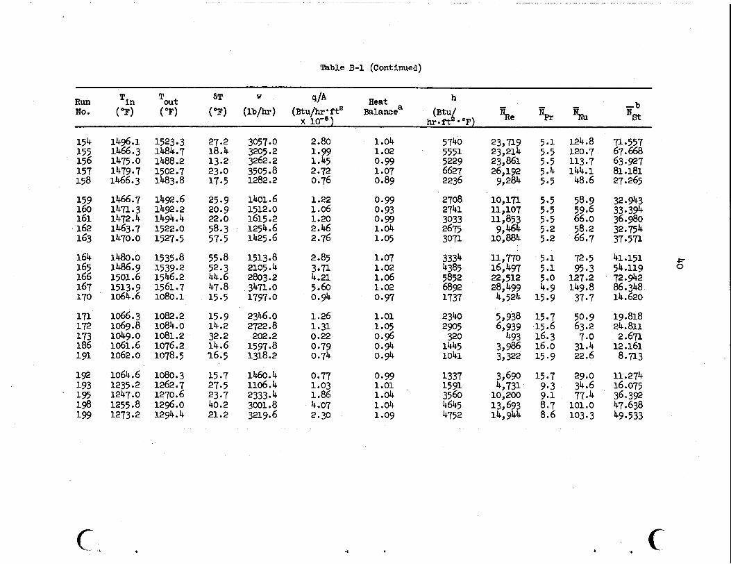
Table B-1. Experimental Data for Heat-Transfer Studies Using the Salt LiF-BeFo-ThF4-UF4; 67.5-20.0-12.0-0.5 mole $
4/A Heat h - b 6T W Tout Run Tin No. ( OF) (OF) %e NPr "u %t (OF) (lb/hr) (Btu/hr*fta Balancea ("q
x 10-6) h e f t *OF)
1388.3 1362.7 1383 9 7 1379.1 1418.0
1456.2 1488.2 1097 9 1082.7 1081.5
1089.8 logo. 6 1029.6 1036.3 1062.8
1075.4 1048.2 1064.0 1076. g 1093 5
1460.4
1469.4 1477.0 1486.7
1460.6
1436.0 1415.8
1436.6 1438.4
1474.4
1507 9 1537.8 1156.4 1163.3 1177.1
1159.9 1160.2 1118.7 1134.8 1117.7
1135.7 1103.4 1115. g 1131 .o 1148.3
1482.9
1501.8
1489.5 1488.4
1513.4
47.7 53.1 54.7 57.5 56.4
51.7 49.6 58-5 80.6 95.6
70.1 69.6 89.1 98.5 54.9
60.3 55 -2 51.9 54.1 54.8
22.5 28.9 19.0 24.8 26.7
2532.0
1807.2 1387.2
1185.0 2191.2
3206.4 1636.8 250.8 279.6
256.2
1785 .o
1910.8 2007.6 2199.6 2307.6 2506.8
1166.4
2968.2
227.4
221.4 155.4
1700.4 2093.4 2458.2 2784.6
4.07 2.48 3.33 2.30 4.16
5-17 5.36 3.23 0.68 0.90
0.54 0.60 0.66 0.52 3-30
3.87 3.73 3 -85 4.20 4.63
0.89 1.66
2.05 2.51
l .34
1.05
1.05
1.12 1.01
1.04
1.04 1.00
f.O1 1 .oo
1.02 0.97 0-93 0.93 1.04
1.04 1.04 1 .Ob 1.04
1.05
1.03
0.94 1.03 1.01 1 .oo 1.09
4882 2831 3617 2302 4590
6192 6462 1936 396 427
407 381. 357 358
1940
2200
2513 2727 3068
2230 3434 3977 4573 5426
2129
15,993 8,345
11,419 7,495
14,917
21,647 25,119 5,005
738 839
673 760 550 405
4,940
5,523 5,304 6,026 6,573 7,583
8,393 12,260 15,282
21,235 18,300
6.3 6.6 6.3 6.3 5 *8
5.5 5.1
13.1 13.5 13.3
13.5 13.4 15.9 15.3 14.5
13.8 15.0
13.2
5 -6 5.5 5.5 5 *4 5.6
14.6 14.0
106.1 61.5 78.6 50.0 99.8
134.6 140.4 42.1 8.6 9.2
8.8 8.3 7.7 7.8
42.2
47.8 46.3 54.7
66.7
48.5 74.7 86.4 99.5
117 9
59.2
56.000
26.270
31 902 41.497
54.082
74.415 79 762 16-713 3 359 3.563 3.488 v)
3 9 265 2.821
16.148
w
2.944
18.56? 17.459 20.984 23.072 26.549
27.007
56.022 65.520
41.743 48.472
~ . . .. . . . . . . . - .- . . .
Table €3-1 (Continued)
h
hrof t *OF)
- - - -b q/A Heat 6T W Run Tin Tout (OF) (OF) (OF) (lb/hr) (Btu/hr*ft' Balancea @tu/ %e NPr "U NSt x io+)
NO.
154 155 156 157 158
159 160 161 162 163
1496.1 1466.3 1475.0 1479- 7 1466.3
1466.7 1471.3 1472.4
1470.0
1480.0
1463.7
1486.9 1501.6 1513 9 9 1064.6
1066.3 1069.8
1061.6 1062. o 1049.0
1064.6
1247.0
1273.2
1235 e2
1255.8
1523 3 1484.7 1488.2 1502.7 1483.8
1492.6 1492.2 1494.4 1522.0 1527 5
1535.8 1539.2 1546.2 1561.7 1080.1
1082.2
1081.2 1076.2 1078.5
1080.3 1262.7 1270.6 1296.0
1084.0
1294.4
27.2
13.2 23.0 17.5
25.9 20.9 22.0 58.3 57.5
55.8 52.3 44.6 47.8 15.5
15.9
18.4
14.2
14.6 32.2
16.5
15.7 27.5 23.7 40.2 21.2
3057 0 3205.2 3262.2 3505 8 1282.2
1401.6 1512.0 1615.2 1254.6 1425.6
1513.8 2135.4 2803.2 3471.0 1797 0
2346.0 2722.8 202.2 1597.8 1318.2
1106.4 2333 4 3001.8 3219.6
1460.4
2.80 1.99 1.45 2.72 0.76
1.22 1.06 1.20 2.46 2.76
2.85 3-71 4.21 5.60 0.9
1.26 1.31 0.22 0.79 0.74
0.77 1.03 1.86
2.30 4.07
1.04 1.02 0.99 1.07 0.89
0.99 0.93 0.99 1.04 1.05
1.07 1.02 1.06 1.02 0-97
1.01 1.05 0.9 0.9 0.94
0.99 1.01 1.04 1.04 1.09
5740 5551 5229 6627 2236
2708 2741 3033 2675 3071
3334 4385 5852 6892 1737
2340 2905 320 1445 1041
1337 1591 3560 4645 4752
23,719
23,861 26,192 9,284
10,171
11,853 9,464
16,497 22,512 28,499 4,524
5 , 938 6,939 493
3,986 3,322
3,690 4,731 10,200 13,693 14,944
23,214
11,107
10,884
11 770
5.1 5.5 5.5 5.4 5.5
5-5 5.5 5.5 5 -2 5 92
5 01 5 01 5 00 4.9 15.9
15.7 15.6 16.3 16.0 15.9
15 -7 9.3 9-1 8.7 8.6
124.8 120.7 113.7 144.1 48.6
58.9 59.6 66.0 58.2 66.7
72.5 95.3 127.2 149.8 37.7
50.9 63.2 7.0 31.4 22.6
29.0 34.6 77.4 101.0 103.3
71 557 67.668 63.927 81.181 27.265
32.943 33 394 36.980 32.754 37 571
41.151 54.119 72.942
14.620 86.348
19.818 24.811 2.671 12.161 8.713
16.075 36.39
49.533
11.274
47.638
-!= 0
a * ., c

.. . . . . .. . . . . . . . ... . ... - . ~ . ... .... " . . . , .. . . ~. ..I. I _ _ _ _ _ .__" ,._I__.I. .. ~ ....-...----I.
6' I
Table B-1 (Continued)
h - - - -b 9/A Heat a
x h r - f t *OF)
61 W Run Tin Tout ( OF) (OF) (OF) (lb/hr) (Btu/hr*fta Balance (BtUl %e NPr "u *st
No.
200 1279.6 1303.7 24.1 3392.4 2.76 1.07 5050 16,088.0 8.4 109.8 53.017 201' 1237.8 1263.8 26.0 1351.2 1.18 1.07 2406 5,892.4 9.14 52.3 24.7 202' 1250.7 1272.6 21.9 1717.8 I. .27 1.01 2762 7,660.9 8.94 60.0 28.6 203' 1252.2 1276.2 24.0 2050.2 1.66 1.16 4029 9,200.0 8.89 87.6 41.9 204' 1258.4 1282.4 24.0 2299.2 1.86 0.99 3625 10,435.5 8-79 78.8 37.7
205' 1229.9 1255.0 25.0 1395.0 1.18 1.01 2119 5,910.9 9.41 46-1 21.5 206' 1231.7 1255.4 23.7 1704.0 1.36 1.10 3004 7,238.9 9-39 65.3 30.7 207C 1243.6 1268.1 24.5 2036.4 1.68 0.97 3122 8,947.4 9-08 67.9 32.1 208c 1247;2 1270.6 23.4 2338.8 1.84 1.12 4337 10,359.7 9-00 94.2 44.9
210 211 212 213
214 215 216 21 7
218 219 220
1132.4 1168.4 1203.4 1138.1
1097. 9 1248.1 1258.3 1280.6
1288.1 1293.8 1118.5
1156.1
1226.7 1168.7
1149.6 1256.1 1276.2 1310.6
1383.2
1215.4
1341.7
1155 - 7
70.1 150.8 59.9 30.6
51.7 8.0 18.0 30.1
53.6
136.1 89.4
2110 2105 2102 2654
2807 2887 2914 2791
275 3 1593 1140
1.69 3.38 1.69 2.76
4.92 0.79 1-77 2.85
5 -03 5.04 1.51
1.01 1.01
1 .Ob 1.03
1.01 0.97 1.03 1.05
1.03 1.03 1.02
2416 3049 2823 3477
3573 4335 4490 4616
4915 2999 1082
6,512 7,696 8,230 8,566
8,297 12,374 12,957 13,454
14,035 8,620 3,554
12.5 10.8 10.2 12 ;2
13.3 9.2 8.8 8.2
7.7 7.3 12.8
52.5 66.3 61.4 75 -6
77.7 94.2 97.6 100.3
106.9 65.2 23.5
22.15 28.96 27 89 32-07
c- P
31 -27 44.98 46.89 49.10
52 56 32.12 9.60
a Heat balance = (sensible heat gained by f l u i d + heat l o s s ) / ( e l e c t r i c a l heat generation). %ist = a Isu (W P r (p/ps).-0*l4 .
Test sect ion oriented ve r t i ca l ly . C

mble B-2. Experimental Data for Heat-Transfer Studies Using the Salt Hitec (KNO, -NaN08-NaNG ; 44-49-7 mole $)
h d A Heat - - b
6T W Tin Tout Run No.
(OF) (OF) (OF) (lb/hr) (Btu/b:bta x 10 1 Balancea %e % %u ijst
87 537.6 677.3 139.7 157.2 0.85 0.99 283 5 2,314 9.3 17.0 7.34 88 540.8 591.3 50.5 1375.2 2.69 1.05 24%. 4 15,450 11.3 150.0 64.3 89 567.5 621.0 53.4 2071.8 4.30 0.9 3516.6 25,640 10.2 211.0 93.1 96 574.8 624.3 49.5 2195.4 4.21 1.08 4450.9 27,578 10.1 267.1 119.7 97 601.4 650.7 49.3 1589.4 3.04 1.00 3045.6 21,716 9.3 182.7 84.2 98 698.4 658.5 50.1 1097.4 2.13 1.06 2473.8 15,349 9.1 148.4 69.3 gg 618.5 672.5 54.0 630.6 1.32 1.03 1386.4 9,165 8.7 83.2 39.2
101 608.8 702.4 93.6 592.8 2.15 1.10 1332.4 9,065 8-3 79-9 37.6 102 633.1 657.2 24.1 640.2 0.60 0.99 1656.8 9,142 8.9 99.4 47.7 103 618.8 634.8 16.1 1551.6 0.97 1.05 4151.9 20,848 9.4 249.1 117.6 104 582.2 669.1 86.9 1603.8 5.41 0.99 3096.6 22,357 9.1 185.8 84.1
Heat balance = (sensible heat gained by fluid + heat loss)/(electrical heat generation). a

43
APPENDIX C
COMPUTE3 PROGRAM

.


ISN C078 GO TO 420 ISN 0679 408 D l 11 11 576.+ 11110.-1576. )/l36.0O-33.001*l Dl I l-33.03)l ISN 0080 IF lDlIl.GE.1635.. LNO.D(Il.LE.16l9.l D l I l=01 II+Oo.4
ISN 0090 ISN 0091 -I.-- I S M 0092 ISN OC93 ISN .O.C94 ISN 0095
23 FiIRHATilH DO 25 1=1
J=D! -- P R I N
2 4 FORM 25 C ON1
ISN 0096 D l 4 l l - D U l ISN 0 0 9 1 01 42 I =DU( IJN. acoa- - . - ~ FTC=OUJ+I 194 0099 C TC =DU I42 ISN 0100 UYAVG=AVG ISN 0101 C4LL TKEA
- - _. - -
'I 4
ISN 0102 PRINT 51
U R Q l O f - ___ _ _ - Q 0 . 3 8 . - l l ~ . N . - ISN 010s PRINT 52.i.W-II i . c t r i
ISN 0103 5 1 F'3RMAT lH1 r4Xr9HSUBSCPI PT 16X16HU CATL*9Xr6HC CAT4 1
ISN 0106 52 FCRYA 11 1 X r I 3 9 OX rF e.2rOX 9 FO.2 I ISN 0107 5 8 C ON11 hUE
C COhSTANTS FOLLCW. THE THERMAL K ' S #RE TEPP CCPENDENT R1=.180/2.
ISN O l l l ISN 0112
ISN 0113 ISN 011.4 ISN 0115 ISN 0116 ISN 0117 ISN 0118 ISN 0119 I sN_-0
ISN 0 194 0 ISN 0 ISN 0 L9-0 ISN 0 ISN 0 ISN (r ISN 0
1SK.Q I S Y 0
1SN 0
ISN a
19 a
!?
.I u 11 12 .2
12
!O _.
! I !2 13 !4 13 ... . . !6 !7
C
.. ..
n3 R4 K 1 K 1 a3 K4
L. SP DA
n=
ole-0.5
xLI l l= .750 TSNO-OF C G N S T A N ~ S
. . - XLlI )=XLlwl+DX
6 0 CONTI hUE T4D=lO (271 +Dl281 112. 141 = I D (29) +Dl301 I 12. T88 I= (Ol31 l+Dl32l ) 12. 1 8 6 0 ~ ~ 0 ~ 3 3 1 ~ 0 1 3 4 ~ l 1 2 ~ IFlTAO.GT.TAIlG0 TC 61 T I =TAX G J TO 62
6 1 74=TAO
7944 7988
79080 79801
79cc 19cc1 79CCZ 79cc3
7900 80
804 b0a1
808 80c 80d
81a 818 100 101 110
aoE
1 20 132 133 134 135 136 137 139 140 141 1 SO 160 110 180 190 20t 210 220 2 30 236 240 2 50 255 260 270 280 285 2 90 390 305 310 315 320 325 330 335 340
c ,

: I 1 1 1 1 i I I 1 I 1 i 1 1 I 1
SN G 5h 6
LSN 0 ‘SN 0 SN 9 SN 0
I SN- _O SN 0
ISN 0 iSN 0 ISN 0 ISN 0
1SN 0 1 9 4 0 ISN 0 ISN 0 ISN 0
19! -0
1 1 1 1 1 1 1 I 1 1 1 I 1
1 1 1 1
i
3 3 3 4 4 4 4 4 4 4 4 4 4
5 ,5 ,5 5
3
6 6 2 IFlTBBO.GT.TB8Il 6(! T J 6 3 ’b - TB b i t~ e1 9 G 1 TO 64 0 63 199=Tf180 1 64 C3NTINM 2 I F IT4-188l66r68r68 -- 3 ... 6 6 l IN=T4 4 i i u t = i a e 5 63 TO 70 *6 58 TIN-TFB 1 lDUT=TA *8 70 CONTINM
.- - . I F ITA-T.B81 .73 r?l.r71 71 ’60 12 I = l * 2 4
11 WZ5-I 12 TO11 l=ClMl 13 7 2 CONTINCE 14 G(1 TO 80
345 350 355 3 60 365 390
410 420 53c 440 450 460 470 475 480 490 500
400
!sn 0152. 73-00 15 J=lp24 . . 510 ISN 0156 T O ~ I I = C ( I l 520 ISN 0157 7 5 CONTINCE 530 ISN 0158 8C CONTINLE 540
C CARE YUST bE TLKEN klTH REGARD TO SIGN CCLVENTION FOR FOLL’WIING 0 AN0 01 550 ISN 0159 QWM=400. /03.6*0 ~41)*200.*3.412/0149~ 560
ISN oid5 OtL=K4*.315*17. I O . /12. 01 IO 143l-OI25l I /OXL+lD(44i -01 26 I l /bxBl
ISN 0169
1% 0171 OBAL=I9F-OlCLLI /OW*
s = % O T * SPH1 *I TOUT-1 I N I ISM 0170 OODP= OF /12. *3.14*~1*Ll* i44.
1.sn-o17r-. _ _ - - _ x i ~ . ~ e - . . - _ _ . . . ISN 0113 X l = X l - e250
ISN 0175 X2 =X 2- 2 50 1% 0174 X2=F TC +C TC-1
18- o n & . 110 PRINT 111 ISW 0117 11 1 F JRMAT I lHlr09X r l H X r l l Xr3HXIDr 10x1 1HH r l l X r ZHTBr 1 l X rZHTIrllXr2HTO
8 r l2X v2HNtJr 1 1 X r 2rR €9 12X r2HPR I - ~ - _ - . - - ISN 0118 ISN 0119 ISM 0180 ISN 0181 ISN 0182
IS?+ 0183 ISN 0184 I!% 0185 ISN 0186 1% 018s ISN 0189 ISN 0190 194 0191
11 2
- e 6 -
XOO-X/ 12.*RlI TB 11 )=TIN t QoCP*3 ~ 1 4 * 2 ~ * R l * X / ~ O C T / S P H 1 / 1 4 4 ~ H I I I *OtOP/ I T I I I 1-1 e t I I I C4LL PPCP(AEh0rPRNCr Ivu rRHOrTB( I I r R l r CCkOr SPHlt MOOT I
510 5 75 576 577 578 580 585 590 610 640 650 660 71 0 720 730 140 810 823 821
840 841
a30
e45 a so 851 852 862 863 064 865 870
890 895
e 80

. C P R 1 N l 97.G
I S N 0247 PRINT 410rCDDP
ISM 0 1 9 2 ISN 0 1 9 3 ISN 0194 ISN 0195 ISN 0196 I S N 0191 I.SY-0 19 8 ISN 0199
I S N 0201 ISN 0202 ISN 0203 1sN-Bzb4 I S Y 0205 1% ape 1SN 0207 ISN 0208 1SN OM9
I s N orno
- . NUN011 l = H l I )*2.*Pl /12./CCNO PRINT 114rX r X O O * H I I l * T I 1 I I 9 1 1 I 1 I ;TO1 I l r NUN01 1 lrREYO*PPNO
1 1 4 FORMAT (1HO19F13.4) 1 1 5 CONTINLE
HA VGOA VG I H rFTC r CTC 9x1 X2 1 PRINT 450rHAVG
I _ _ 450 F3RMATI lH3?~AVG H BTU/HRSOFTOEGF 0 * rClO.2) I M4VGdVGf T ~ ~ F T C ~ C T C I X ~ 9x21 I PRINT 4 5 1 9 LAVG
BAVG~AVGITB~FTC ~CTCIXI rX2) I PRlNT 452nPAVG
4 5 1 FORMkTl1HO~'AVG INhER MALL TEMP DLGF 0 'rF10.3)
452 - FORMAl11.HO~8.AVC RULK TEPP OEGF = 'rF10.31 04VGoA VG I TO*FTC *CTC*Xl 9x2 1
1 PRINT 4 5 3 * C A S
I 1 PR 1 NT 4 5 4 hUAVG
453 FORMATllHO~*AVG OUTER MALL TEMP DLGF 0 *rF10.31 NUAVGoAVCI kLNOrFTt tCTC 9 x 1 rX2 j
. . I S N 0228 PRINT 99rRHO ISN. 0 2 2 9 9 9 FqRMAT 11HOv'BULK SALT OENSITV LfVFT3 * r T 3 5 r F l b . Z l ISN 0230 PRINT l001PU ISN 0 2 3 1 100 FORMAT IlHC*.BULK SALT VISCOSITV LBlHPFT = 'rT35rF10.3l ISN 0 2 3 2 - _---- .-..!w_N~--~@1 *corn, - ISN 0233 101 FORMAT I lHOv'BULK SALT CCNO BTU/HRFTDEt%F * * T35*F10.5) ISN 0234 PRINT 4 7 2 e T I N I S N 0235 472 FORMATl lHO~* INLET TEPP OEGF 'r135rF10.31 1% 0236 PRINT 473rTOUT ISN 0 2 3 7 473 FORMATl lH0~'OUfLET TEMP DEGF 0 ' .T35.F10~31
ISN 0240 4 1 4 F 3 R M A T l l H O ~ * T O U l - T I N DEGF 0 ' rT35tF10.3) I S M 0241 PRINT 471 . C D M - - . - - . - . .._. ISM 0242 411 FURYllTf lHOr*MASS FLOk PATE LE/HR 0 'rT35*F10.3) ISN 0 2 4 3 PRINT 477.EENO I S N _ O ~ . _ _ _ - . . 4 ? 7 . F 3 ~ ~ l l T f IHC**RULK REVNCLCS NO& 0 ' *T35*F10.21 ISN 0 2 4 5 PRINT 4 7 6 PRNO ISN O H 6 478 F'JRYAT (lHC*'BULK PRANCTL hO. 0 * r T 3 5 r F 1 0 . 3 l
897 900 91 0 9 2 0 930 935 940 9 5 0 9 5 5 9 60 970 975 900 5 9c 9 9 5
low 1005 1010 101 5 1017
1019 1020a 102 OB
102993 l 0 2 0 B 2 1020c 10200 1020E 1020F 10z0t 1020J
1020J3 102OJ4 102055 1 0 2 0 L l 102012 1020L3
1050 1055 1060 1065 1080 1090 1110 1120 11 30 1140 A 1 50 1160
A180 11 85 11 90 1200 1210 1220 1230
ioin
i i ro
c

4 C.
ISN 0248 470 FgRMAT(lHO**NET HEAT FLUI PTU/HRSOFT = * 11331E12.51 ISN 0279 - P R l Y T 4f6*CBAL ISN 0250 476 FORMAT (lHO**HEAT BAL4hCE **135*F13.3J ISN 0251 DEFH=MOOT*SPHl*( TOUT-TIN J / (2.*3.14*RI *L/ 144.W WAVG-BAY(;l I ISN 0252 P4 I NT 475 t CEFH ISN 0253 415 FC)RMAT(lHl t * H BY DEF BlU/HPSQFlDEGF **T35rF10.2J I S H P ~ 4 - ~. . - - NNO*D€FHf2.*R1/12. /CCNC ISN 0255 P R I Y T 4751 tNNO ISN 0256 4751 FORMAT (lHO**NUSSELT NC. * rT35rFlO.21
C FROM MERE ON THE YNO USE0 ltILL BE THE INTEGRATED VALUE ISN 0257 ISN 0258 1 9 - on9 ISN 0260 ISN 0261 ISN 0262 ISN 0263 ISH 0264
ISN 0266 IsH-0267 ISN 0268
E ?! -o_-B3-- -
NYO=NUAVG GRNO= 01 **3*EETA*32 .2*RHO**2* (WAVG-BAVGI / ( YU/36CO. l**Z PRIYT -9Bl-rGRIO
GLN0*3.14/4. *RENO*PRhO+Z .*R1/ (X2-Xl I PRINT 4752 rGLNO
4752 FORMAT flHO*'tRAETL NO.(C-81 *rT35*F10.41 BTRHa.O722*lGRNO*PRhO+Z . * R l / ( X Z - X 1) J **O.75
B ~ S ' - F ~ R M A T ~ ~ H O ~ * G R A S H O F ho. = a r ~ 3 5 r ~ 1 0 . 4 ~
09F =NNO/PR hO**O.4 OBHICOND/( Z.*R1/12. J +C .023*( RENO1+0.8 J*( PRNO**O.4) - - PRINT 4111 . e m
ISN O h 4 ISN On5 I F (TA-188) 2001210r210 1mLons- 200 D ~ ~ = ~ O ~ ~ D ~ * I . l _ S * ( ~ Z N O . ~813~139-. 33- - ISM one. .210 DLH~COND/Dl*l~75*~GLhO + BTRCl*r0.33
ISN 0290 STH=SM*(ML*W.l4l ISN 0281 COLH=O.O23*(Dl *GJ*+O .9/Ol*CCNO*rd.667*SPHl**O.33
ISN 0277 GO TO 220
ISN 0279 220 CONlINUE
____ ISN 0267 -- COLH~_CLH*~U**O~.33/MU**O.8 I94 02eO FGRNO=FGPNC/W**2
I F (TA-TBBI 230&!40*240
ISN 0291 GO TO 250
1% 9293 - 250 CONTINUE ISN 0294 CF .CF/YU**C.?3
ISN 0292 240 CL MH 2 L W / YU**G 33 * t 1 + 0 e 0 15* (FG PNC I **Om 3 3 I
i3N Oh5 CRENO=RE NO ISN 0296 PRINT 4911 tCOLH ISN 0291 4811 FIRM41 (lHC**COLBURh T t R B H BTtI/HRSPFlDEGF * iT35rF10.2J ISN 0298 C4LL PROP( REM)*PRNC* IrU rRHOtWAVGtR1 t CCNOt SPHlrMDOT J ISN 0299- STlM=SlTH/ (MW*0.141 ISN 0300 ISN 0301 ISN 0302
1235 1240 1245 1250 1260 1270 1290 1291 1292
1292a 12928
1293 1294 1295 1296 1297 1298 1299 1300 1301 1310 1320 1330 1340 1350 1355 1351 1358 1360
136011 . 13608
1360c 13600 136DE
1361 1361A
1361400 1361AO 1361A1
13618 136181
1361C 13610
1136101 136102 136103 136104 136105 1361D6 i 3 6 I ~ 7 1 3 6 1 ~ 8
1361E 13b1f
1362 13628 1362C
1363 1364

ISN O P 3 . 492 FJRMAT(lHOr-!S-T TUROULEkT H @fU/HRSCFTOEGF ' rT35rF10.2) ISN OM4 PqtNT 4821 rHTRW ISN 0305 4C21 FORMAT (IMOr'HAUSCh TR H ATU/MRSOFTDEGF ' rT35rF10.2 # ISN 0306 PRINT 483rSlM ISN 0307 493 FORMAT (IHOr'S-1 LAMlNIR H BTU/HRSQFTCEGF *rT35rF10.2) ISN 0308 PRINT 484.DLH
isW oi i6 ISN 0320 485 F3RMAT IlHOr'S-T FICTOR ' rT35rF10.3)
ISN 0322 PRINT 486rETL 1SN 0323 496 FJRMATtlHUr'EFF TUDE LENGTH I N * rT35rF10.3# ISN 0324 VRAT+I VRAT/MU)**O.14
P R I N l 485 r STF
JSY..-03zL ___I_ ~. €_Twa5Ll -. --- .- . . I- - . ..
ISN 0325 PRINT 4 e i r m ~ ISIS 0 3 2 6 487 FORMAT ( l H O r * V I S R I T I O TO 0.14 'rT3SrF10.4)
ISN 0328 PRINT 4e8.CFACT 032-2 . - - .QFMES~E*YMT- _ .__
isN 05% 488 FORMAT (1HOr'MART FACTCR 0 rT35rF19.3)
ISN 0330 CALL VLSf lC rFTCrCTCrZ I c A LOOK A T A SMCOM CURVE TWRU DATA POINIS PAY BE EDUCATIONAL
ISN 0331 GO TO 6 -ASLQX+OBz _ _ __ ..-€YO - _ _ __ ___ . - __ AEONS FOR EXTERNAL- REFEREKES
Y
1365 1366
13bbA 1361 1368
1369A 1 3 6 9
136902 1369C1 1369C2 1369C3 1369C4 1869C5 1369C6 1370a 13708 1370c
1372 ~ 1373
1374 1375 1376 1377 1378 1379 1380 1390 1391 1400 1401
i369e I
u 0
t Y c c

COMPILER CPTIONS - NAPEL M A I N ~ C P T ~ O 2 ~ C I Y E C N f ~ 6 ) , S O U R t f , E B C O f t , Y O L I S T ~ O E C K ~ L O A O ~ ~ A P C THIS FUNCTICN CCCYITS 3R0 CROFR CRTHOGCY4L SINS BY AVERAGING VALUES A C BEGINYINC k I T H NO. Y A T X I AN0 ENOINO U I T H I CCNSECUTIVE VALUES AT X Z A
ISN 0002 FUNCTICN AbG(**Y*I t X l * X Z l A ISN 0003 OIWNSION Y(50l 9X(?iOIrb(4lrP('50r4I *SP2(50*41 A I S N 0004 REAL NPILS A ISN n005 A ( l I = O A I S N 0006 A L ( Z I = O A 1% OC07 A(3I=O A I S N 0008 At4110 A 1SN 0009 P( 1111 =I. A I S N 0010 P( 1 r 2 I =I. A
* 1 1
82 3 3 4 Y
1 7
NOEO I T NO1 0 NOXREF .o 1
!O
i5 PO io IO '0 '2 '3
io
ISN .Qoll--. - __ - . P( 1 p . 3 ) 11.1 ISN 0012 P 1 * 41 -1 . ISN 0013 NP-1-1 I S N 0014 DO 490 L m 2 . l ISN OCIS X t L I =L-1
A 74 A 75 A 90 A 95 A 97
A210 1220 A230 A240
I S N 0030 550 C9NTINUE A250 I S N 0031 1513 0032 ISr C 0 3 3 I W DQ3-% ISN 0035 I S N 0036 ISN OC37 ISN 0038 I S N 0039 t SN .0040
ISN OC41 ISN 0 0 4 t ISN 0043
PRINT 6 C O
09 730 J s l r I 600 F'JRMAT ( l H l * l 0 H O R I C I N A L *13HLEAST S C I I A R t S t l O H PGEVI
L $%A 1 U*.P ( J p l I + I t 2 I *Y (J t 2 I +A( 3 1 * F-( J * 3 I + A ( 4 I *e( J 4 1 POE V I (LS-Y tJ+ W l I 1*100./Y( J+M-II PRINT 650*Y(J+C-L I*LS*PCkV
65 0 FOR MA 7 (Ft3.2 t 5 X ~ F 8 . 2 r5X F8 e 2 I 700 CJNTINLE
x 3 =x2- x I
8 /2.1 I 4 b 8
A(4I * (X3-6 .*X3**2/kP+30 ./hP/ NP-I.I*(X3**3/3 .-X3**2 /2. 1-20 ./PP/(NP-I I / ( NP-2.1 * (X3**4 /4 . -X3**3+X3*X3l I
AVG=AI NT/X3 RE TURN €10
.. .
A270 4200 A290 a3c0 A305 A310 A320 A330 A340 A350 A351 A352 A353 A354 A390 A440 A450

COMPILER O f T I OMS - NAY€= M A I N r C P l ~ 0 2 r L I M E C N T ~ 6 0 rSOURCEtEBCUICrYOL1 ST rOECKrLOADrYAPrNOFOI T r N O I OrNOXREF T-THTS F i J N Z ' t l O K W f C R h I N E S ?t#iRRAL K FOR IhCR-8 K 10
194 o m 2 FUNCTICN T l t T E M P F l K 2 0
- .- - ._- - - -.
I S N 0003 TEMPCI tTEWPF-32.1*5. /9. K 3 0 I S N @OO$ I F ~ I E M P C - 4 4 0 ~ l L O r l O r Z O K 4 0 ISN 0035 10 TK=O.ltO+ ( .155-.128) /ZOO .+tTEwPC-?09 1 K 50
?opt.-. .- - GO TO 80 K 6 0 ISN OC07 2 0 I F -tE-kPC=JOO. 1 3 0 r 3 0 1 4 0 K 7 0 ISN 0008 k00 3 C TK =O 1 60+ t e l 74s. 160 1 16 C. ( TE CPC -440 1 I S M OW9 63 TO 00
1m 0011 5 0 TK=0.174+( . 1 9 3 - ~ 1 7 4 1 / 1 0 0 ~ * t T E ~ P C - 5 0 ~ . ~
I S M 0013 65 I F t l E M P C - 7 4 0 . 1 7 0 r 7 O r 7 5
ISN O C l O $0 IF ( lEWPC-68C.15Or5Or6C
!FoCl_z_. - _. GO _t_o eo. I S N 0014 IC TK=U.ZOB+~ . ~ ~ O - . ~ O B I / ~ C . * ( T E C P C ~ ~ O . ) 194 0 0 1 5 GO TO 80
ISM 0017 B C TK=TK*57.82 ISN E016 1 5 TK=0.230+( .248-.2308 /160.*tTFMPC-140.)
Y
R E TURN . €YO
t d
K 90
u110 K 1 2 0 U 1 3 0 K 1 4 0 K 1 5 0 K 1 6 0
U300 ((301
uiao
a1r0

. ..
CCJMP I LC R OP T I ON 5 - NA YE MA I hr IYP 1102 * L I NCCNT 1 6 0 *SOUR CEr t BCOI Cr YOL I ST I OECK r LOA0 r MAPI YO€ 01 Tr NC'I C r NOXREF 1: THIS SUaPlJlrYfkE TAMES 1h AFRLV Y YHCSC 1 S l VILUE IS 4 1 M h I T H I TOTAL A 1 9
I S M O M 2 I S M OC03 I S M 9034 I S N 0005- I S N 0006 194 OW7 Irn 0038 ISN too9 ISN 0010 ISN 0011 I S M 0012 ISN 0013 ISN 0014 ISN 0015 ISM OOl6
.. . .
C CONS~CUTIVE VALUES 4NO REPLACES THIS A R R I V U I T k AN NTH ORCER F I T S!J8ROUTINE V L S t V i M i I r Y l 01 W € NS I ON V I50 I r X I 5 0 I r A I 4 I I P I 50 9 4 I rS P 2 I 501 4 I REAL lyP.LS
A 0 1 1 0 414I=O P I 1 r l I = l . P.ll.21 =I. P t 1 r 31 =l . P I 1 e41 4. NP.1-1 0'1 490 L I Z 9 1 XILl=L- l P I L . l l = 1.
I 52- .ow - . - . - P!& t 2 l =l . -2. * X I L l / hP ISN 0018 I S N 0019
P I L 931 -1 m - 6 . * X I L l /hP+5 *X iL I * I X I L l - 1 I /NP/ l NP-1 I P I L r 4 k -1 .-12.*XlLl /NP*3O.*X I L I * ( X I L l -1 . I /NP/lNP-1. I
a -2O.*X 111 *I X I 11-1. I *I X I L 1-2 I /NP/ I NP-1 I /I NP-2 I ISN 0 0 2 0 490 CONTI I IM ISN 00.21 SP2 I I r 1 I =NP*l. 1sw-oa_zz- - - 1SN 0 0 2 3 I S M 0 0 2 4
. SP21 - - -. . - 1921 = I hP+l I * I hP+2 . I / I 3 e*NPl SPZI 1131 * I NP*l. l * lNP+2 . I *(NP+? I / I 5.+lrP) /I NP-1 I SPZI 1 - 4 1 *I hP*1. I *I hP+2 - 1 *I NP*3. I* ( NP*4. I / I 7.*NPl I1 NP-1 I /lNP-2. I
194 002s 0'1-550 J-1 r 4
1SN 0 0 2 7 A ( J l = A I Jl +VtK*M- l l * P ISC! oozs - -bP. C ONTI.hUE I S M OC29 ISN 0 0 3 0 550 CONTINUE ISN OC31 PRINT 600 ISN 0 0 3 2 630 FIRMAT 11Hlr lOHORIG1h4L ISN 0033 09 700 J= l r I IS!! c o r __ - - _. I F lN.LT.31 A l 4 l * O ISb 0 0 3 6 IFlN.LT.2l A131+0
1% 0026 00 soa a = i 9 t
A I 5 1 *A I J l / J P Z l I IJI.
K r J l
13HLEAST SCUARES r 10H POEV I
ISN OC38 I S M 0040 I S N 0041 ISM o w
1 F IN. 11.1 I LSsL I11 *P( J r 1 1+112 I * P I 512 1441 3 l * F l J r 3 ) + A I P Ok VI I L 2-V I J+ Y- 1) I *100. / V L .I+ M-1 I
A 12) I'J
) *P I Jr 4 I
lur.9*3 - - 65 0 FORMAT [email protected] ISN nC44 V I J+M-l I =LS I S M OC45 XC C'JNTINUE ISN 0046 RE 1URN Isrl O C 4 7 E YO
A l l A 2 0 A 30 A35 b 4 0 A50 A 60 A 70 A 7 2 A73 A 74 A 75 A 90 A95 A 97
A100 a110 A120 A 1 30 A 1 3 1 A135 A140 A150 A I 60 A170 1 2 0 0 A210 A220 A230 A240 A250 A270 A280 A290 A294 A295 A296 A300 A305 A31C A320 A 3 3 0 A350 A370 A371
ul W


55
,
APPETJDIX D
CHEMICAL ANALYSES AND PHYSICAL PROPERTIES OF THE SALT

i

li II
57
Table D . l . Analyses of the Fluoride Salt Mixture (LiF-BeFz-ThFc-UF4; 67.5-20.0-12.0-0.5 mole 4 )
Before, During, and After Heat- Transfer Determinations
Weight 4 Impurity
Before Duringa After
L i
Be Th
U
F N i
Cr Fe
S N a
7.14 2-57
1.87 42.1
45.4
20 PPm
e 5 PPm
78 PPm C10 ppm
-
7-27 2-53
1.84 41.3
46.4 -
6.64 2.46
43.5
45.4 1.72
-
- 0.66
a Analysis made jus t p r ior t o removal of the f i rs t t e s t section.
\

58
Table D.2. Thermophysical Woperty Data f o r Molten Salt Mixture LIF-BeF,-ThF4 -uE, (67.5-20-12-0.5 Mole $1
Uncertainty Ref. ~~~~ ~~~
p ( lb / f t -h r ) = 0.187 exp [8000/T(oR)]a k (BtU/hr*ft-OF) = 0.69 b
p (lb/ft3) = 230.89 - 22.54 X lom3 t C
Liquidus temperature e 895 "Fa
(Btu/lb* OF) = 0. 32ka P
12
13
12
12
12
aEstimated values f o r the salt mixture LiF-BeFz-ThF4-UF4 (68-20-
bMeasured value fo r the subject salt mixture.
11.7-0.3 mole 4).
f

59
ORNL-TM-4079
' L
c
1. 2. 3. 4. 5. 6. 7. 8. 9. 10. 11.
12-21. 22.
23-27. 28. 29. 30 9
31 32 33 34 9
35 36 9
37 38 39. 40. 41. 42. 43 44. 45
46-55. 56 57 58 59. 60. 61. 62.
INT-L DISTRIBUTION
L. B. Alexander J. L. Anderson S. E. Beall M. Bender E. S. B e t t i s E. G. Bohlmann C . J. Borkowski C. E. Boyd R. B. Briggs R. H. Chapman S. J. Claiborne, Jr. J. W. Cooke W. B. Co t t r e l l B. Cox (K-25) F. L. Culler J. H. DeVan J. R. DiStefano S. J. Di t to A . S. Dworkin W. P. Eatherly D. M. Eissenberg J. R. Engel D. E. Ferguson L. M. Fe r r i s A. P. Fraas J. H. Frye C. H. Gabbard R. B. Gallaher W. R. Gambill R. H. Guymon P. N. Haubenreich R. B. Heimdahl H. W. HoffkDan W. R. Huntley P. R . KEtsten R. J. Ked1 J. J. Keyes, Jr. 0. H. Klepper A. I. Krakoviak T. S. Kress
63 9
64. 65 66. 67 68. 69 70 71 72. 73 74 75 76 9
77 9
78 79 9
80. 81.
82-83. 84. 85 86. 87 88. 89 90 91 92 93 94 95 96 9
97. ~
98 99
100-102. 103
104-105 106.
J. W. Krewson C . G. Lawson M. I. Lundin R. N. Lyon H. G. MacPherson R. E. MacPherson H. E. McCoy H. C . McCurdy D. L. McElroy H. A. McLain L. E. McNeese J. R. McWherter A . S. Meyer A. J. Miller S. L. Milora W. R . Mixon R. L. Moore A. M. Perry J. Pidkowicz M. W. Rosenthal W. K. Sartory Dunlap Scott J. H. Shaffer Myrtleen Sheldon J. D. Sheppard M. J. Skinner I. Spiewak D. A . Sunberg R. E. Thoma D. G. Thomas D. B. Trauger J. R. Weir G. D. Whitman R . P. Wichner M. K. Wilkinson A . M. Weinberg Central Research Y-12 Document Reference Section Laboratory Records Laboratory Records - Record Copy

107.
108.
109-111.
112-113.
114-130. 131-132.
133 134-135.
136. 137
138-1351 140.
60
EXTERNAL DISTRIBUTION
Branch Chief, Special Technology, RDT, USAEC, Washington, DC 20545 Director, Division of Reactor Development and Technology, USAM:, Washington, DC 20545 Director, Division of Reactor Licensing, USAEC, Washington, IX! 20545 Director, Division of Reactor Standards, USAEC, Washington, IX! 20545 Manager, Technical Information Center, USAEC (For ACRS Members) MSBR Program Manager, USAM:, Washington, DC 20545 Research and Technical Support Division, USAEC, OR0 Technical Information Center, USAEC D. F. Cope, RDT S i t e Office, ORNL A. R. DeGrazia, USAEC, Washington, IX! 20545 Norton Haberman, USAEC, Washington, Dc 20545 Kermit Laughton, RlYT S i t e Office, ORNL
‘L
?