force gauges kraftmessgeräte force gauges...force gauges, with or without an interface are ideal...
TRANSCRIPT
KraftmessgeräteKraftmessgeräte
www.pce-instruments.com/english 8382 www.pce-instruments.com/us
Force gaugesForce gauges
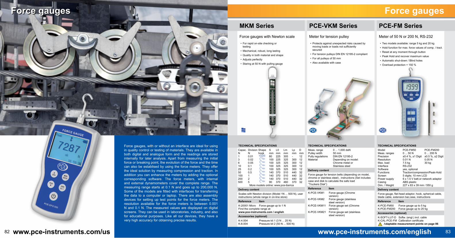
Force gauges, with or without an interface are ideal for using in quality control or testing of materials. They are available in both digital and analogue form and the readings are stored internally for later analysis. Apart from measuring the initial force or breaking point, the evolution of the force and the time can also be establised by using the force meters. They offer the ideal solution by measuring compression and traction. In addition you can enhance the meters by adding the optional corresponding software. The force meters, with internal and external dynamometers cover the complete range. The measuring range starts at 0.1 N and goes up to 200,000 N. Some of the models are fitted with interfaces for transferring the data to a computer or laptop. There are also assembly devices for setting up test points for the force meters. The resolution available for the force meters is between 0.001 N and 0.1 N. The measured values are displayed on digital screens. They can be used in laboratories, industry, and also for educational purposes. Like all our devices, they have a very high accuracy for obtaining precise results.
Force gauges
TECHNICAL SPECIFICATIONSMeas. range 0 ... 1,000 daNPulley width 50 mmPully regulations DIN EN 12195-2Material Depending on model: Chrome metal or Stainless steelDelivery contentForce gauge for tension belts (depending on model, chrome or stainless steel) , instructions (Set includes case and disk to calculate the safe load “Truckers Disk”)Reference Item K-PCE-VKM1 Force gauge (Chrome version) K-PCE-VKM2 Force gauge (stainless steel version) K-PCE-VKM11 Force gauge set (Chrome version) K-PCE-VKM21 Force gauge set (stainless steel version)
PCE-VKM SeriesMeter for tension pulley• Protects against unexpected risks caused by
moving loads or loads not sufficiently secured
• For tension pulleys DIN EN 12195-2 compliant• For all pulleys of 50 mm• Also available with case
TECHNICAL SPECIFICATIONSCapac. Division Shape S L0 Lm Lp DN N hook mm mm mm mm mm1 0.01 80 225 305 - 123 0.02 100 225 325 300 126 0.05 100 325 325 300 1210 0.1 100 325 325 300 1225 0.2 100 325 325 300 1250 0.5 140 370 510 440 32100 1 140 370 510 440 32200 2 140 370 510 440 32500 5 90 370 460 370 32
More models online: www.pce-ibericaDelivery contentScales with Newton division (Model 1N ... 500 N), user instructions (whole range in on-line store)Reference Item K-20001 Micro Force gauge up to 1 N Find the complete range at: www.pce-instruments.com / englishAccessories (optional) K-4.004 Pressure kit 1 (3 N ... 25 N) K-8.004 Pressure kit 2 (50 N ... 500 N)
MKM SeriesForce gauges with Newton scale• For rapid on-site checking or
testing• Mechanical, robust, long lasting• Quality in both material and shape• Adjusts perfectly• Staring at 50 N with pulling gauge
TECHNICAL SPECIFICATIONSModel PCE-FM50 PCE-FM200Meas. ranges 0 ... 50 N 0 ... 200 NPrecision ±0.4 %, ±1 Digit ±0.5 %, ±2 DigitResolution 0.01 N 0.05 NMax. load 7.5 kg 30 kgInterface RS-232Software yes, optionalFunctions Traction/compression/Peak-HoldScreen 5 digits; 10 mm LCDPower supply 6 x 1.5 V batt.or network adaptorCasing ABS plasticDim. / Weight 227 x 83 x 39 mm / 550 gDelivery contentForce gauge, flat-head adaptor, hook, spherical cable, blade cable, extension bar,case, instructionsReference Item K-PCE-FM50 Force gauge up to 5 kg K-PCE-FM200 Force gauge up to 20 kg Accessories (optional) K-SOFT-LUT-D Softw. (engl.) incl. cable K-CAL-PCE-FM Calibration certificate
Adaptable measurement points on page 86
PCE-FM SeriesMeter of 50 N or 200 N, RS-232• Two models available: range 5 kg and 20 kg• Hold function for max. force values of comp. / tract. • Reset at any moment through button • Peak Hold and recover maximum value• Automatic shut-down / Blind holes• Overload protection = 150 %

TOPseller
TOPseller
85www.pce-instruments.com/englishwww.pce-instruments.com/us84
Force gaugesForce gauges
TECHNICAL SPECIFICATIONSMeas. range 0 ... 500 N Resolution 0.05 N Precision ±0.2 % of meas. rangeMax. overload. 50 % of meas. rangeInterval Adjustable 10 / 5 / 2 / 1 valuesScreen Graphic screen, 160 x 128 pxMemory Manual or automaticInterface RS-232 series / 9 pol., USB 2.0 Operating cond. -10 ... +40 °C / 20 ... 80 % R.h.Power supply NiMH batteries or network adapt.Force input part 7 mm length, 6 mm threadDim. / Weight 144 x 73 x 33 mm / 700 gDelivery contentDynamometer., flat cable adpt., spherical, blade, hook, bar (90 mm), softw., cable RS232, network cable, instr.Reference Item K-PCE-DFG 500 Force gauge up to 500 N Accessories (optional) K-CAL-FG Calibration certificate K-ADP-UNI Meas. point plate adapt.
Adaptable measurement points on page 86
PCE-DFG 500Digital dynamometer up to 500 N• 0.2 % error of range / overload protection ±50 %• FunctionPEAK (MIN / MAX) / limit values• Memory for 1,000 values / graph analysis• Screen graphic with automatic alignment• Automatic shut-down / robust aluminium casing.
TECHNICAL SPECIFICATIONSMeas. range 0 ... 100 kg / 0 ... 981 NPrecision ±0.5 % ±2 digits / ±5 NResolution 0.05 kg / 0.2 NMeas. unit Gram / NewtonMax. overload. 50 % (Max. 150 kg)Interface RS-232Software Yes, optionalFunctions Traction/compresion/Peak-HoldScreen 5 digits; 10 mm LCDPower supply 6 x batteries 1.5 V or networkDimensions Cell: 130 x 51 x 18 mmWeight Ext. cell: 380 g / device: 450 gDelivery contentDynamometer with external cell with 2m cable, case, user instructionsReference Item K-PCE-FM1000 Dynamometer up to 100 kg Accessories (optional) K-SOFT-LUT-D Software incl. cable RS-232 K-CAL-FG III Calibration certificate K-NET-LUT Network component
Adaptable measurement points on page 86
PCE-FM1000Dynamometer with ext. cell, <1,000N• External cell with 2 m cable• Hook and screw-in bracket for the sensor• RS232 interface/software & meas. point (option.)• Hold function / reset button• Peak Hold and recover maximum value• Overload protection = 150 %
TECHNICAL SPECIFICATIONSMeas. range 20.00 kg, 44.10 lb, 196.12 NPrecision ±0.5 % + 2 dig., with 23 ±5 °CResolution 0.01 kg, 0.01 lb, 0.02 NScreen Min. 0.02 kg, 0.07 lb, 0.3 NMemory SD memory card 1 ... 16 GBInterface RS-232 / USBScreen 5 digits, 16 mm LCDMax. overload. Max. 30 kg Power supply 6 x 1.5 V AA or adaptor 9 VOperating cond. Temperature: 0 ... +50 °C Humidity: < 80 % R.h.Dim. / Weight 215 x 90 x 45 mm / 650 gDelivery content Force gauge, SD card, card reader, 1x 120 mm extension, 4x adaptors, case, instructionsReference Item K-PCE-FG 20 SD Force gauge Accessories (optional) K-CAL-FG Calibration certificate K-ADP-UNI Meas. point plate adapt.
Adaptable measurement points on page 86
PCE-FG 20SDForce gauge / SD card / 200 N• Meas. range: 0 ... 196,12 N (< 20 kg) • Units of measurement: kg, lb, N• Data memory on SD card• Interface RS-232• Maximum value function• Screw-in extension bar• Reset button
Cable length Approx. 3 m (external cell)Weight without cell Approx. 400 g (without batteries)Delivery content Series PCE-FB with internal cellMeter (depending on model), cab. adaptor blade, flat, spherical, hook, extension bar (90mm), software incl. data cable, network component, case, instructionsDelivery content Series PCE-FB K with external cellMeter (depending on model), external cell incl. hook and bracket, network adaptor, software for analysis and control, RS-23 cable, case, instructionsReference Item K-PCE-FB-200 Force gauge, up to 200 N K-PCE-FB-500 Force gauge, up to 500 N K-PCE-FB-1K Force gauge, up to 1,000 N K-PCE-FB-2K Force gauge, up to 2,000 N K-PCE-FB-10K Force gauge, up to 10,000 N K-PCE-FB-50K Force gauge, up to 50,000 N K-PCE-FB 100K Force gauge, up to 100,000 N K-PCE-FB-150K Force gauge, up to 150,000 N Accessories (optional) K-CAL-FG Calibration certificate K-ADP-UNI Meas. point plate adapt.
Adaptable measurement points on page 86
TECHNICAL SPECIFICATIONSMeter with int. cell Meas. range ResolutionPCE-FB 200 200 N (20 kg) 0.05 N (5 g)PCE-FB 500 500 N (50 kg) 0.10 N (10 g)Meter with ext. cell Meas. range ResolutionPCE-FB 1K 1,000 N (100 kg) 0.2 N (20 g)PCE-FB 2K 2,000 N (200 kg) 0.5 N (50 g)PCE-FB 10K 10,000 N (1,000 kg) 2 N (200 g)PCE-FB 50K 50,000 N (5,000 kg) 10 N (1 kg)PCE-FB 100K 100,000 N (10,000 kg) 20 N (1 kg)PCE-FB 150K 150,000 N (15,000 kg) 50 N (5 kg)Margin of error ±0.1 % of measurement rangeGravitation zone Manually adjustable or by GPSMeasurement units N, g, lb, oz, kg, kgf, lbf, ozfCalibration Possible with 2 weights F2Interval 10 values / sec or 40 values / seg.Functions Traction/Compression/PEAK, (MIN. - MAX. - Hold) / value limit / measures in real-time with software Screen Graphic screen 61 x 34 mm / automatic alignment / backlight, automat. - 0.025 s - 99.9 s (adj.)Software / Interface Incl., for analysis and control, RS-232 and USBPower supply 4x batteries Ni-MH or network component ~230 VOperating cond. -10 ... +40 °CDynam. dimensions. 210 x 110 x 40 mmReceiver 11 mm length, thread M6 x 9 mm (internal cell)
PCE-FB SerieDynamometer for traction and compression with large intervals and Mini SD• Meas. range up to 150 kN (150,000 N) / Max. overload. 20%• Can choose large intervals (10 Hz / 40 Hz)• Internal memory (up to 6,400 values) mini SD card• Value limit function / compares measured values• Statistical evaluation with graphs, multi-lingual menu• Graphic screen with automatic alignment / auto OFF (adjustable)• Incl. analysis software for PC / USB and RS-232 interface

TOPseller
87www.pce-instruments.com/englishwww.pce-instruments.com/us86
Schulungen / ServicePraxisorientierte Geräte-SchulungErweitern Sie Ihr Know-How mit praxisnahen Schulungen von PCE Deutschland
Jede Schulung wird individuell auf die Teilnehmer zugeschnitten.
Diese Schulungen richten sich an Personen, die ein Gerät bei PCE erworben haben, technische Grundvoraussetzungen besitzen und so schnell wie möglich zielgerichtet arbeiten möchten. In praxisorientierten Schulungen wird Ihnen gezeigt wie Sie mit dem Gerät arbeiten müssen um gute und aussagekräftige Messergebnisse zu erhalten.
Die Schulungen können in den Seminarräumen von PCE stattfinden oder auch direkt bei Ihnen in der Firma.
Dauer: In der Regel 4 Stunden (2 Stunden Kennenlernen des Gerätes, 2 Stunden praktische Übungen)
Terminierung: Individuelle Vereinbarung
Voraussetzungen: Die Teilnehmer sollten als Voraussetzungen Grundkenntnisse in dem jeweiligen Fachgebiet besitzen.
Praktische Übung
Theoretische Einweisung
Force gauges
TECHNICAL SPECIFICATIONSForce range 0 ... 509 kg / 0 ...5,000 NDisplacement Max. 214 mmVelocity 0 ... 240 mm /min (adjustable)Use Automatic or manual buttonsPower supply 230 V / 50 HzDim. / Weight 1020 x 400 x 260 mm / ap. 60 kgNecessary adaptors (optional)PCE-PTR 200 / PCE-FM 50 / 200 K-ADP-UNIPCE-FB 200 / 500 K-ADP-UNIPCE-FG 50 / PCE-FG 200 K-ADP-UNI PCE-FG 20SD / PCE-DFG 500 K-ADP-UNIDelivery contentTesting post, power supple cable, instructionsReference Item K-PCE-MTS500 Motorized testing post Accessories (optional) K-ADP-UNI Adaptor for one device K-PCE-SJJ05 Clamp PCE-SJJ05 K-PCE-SJJ11 Clamp PCE-SJJ11 K-PCE-SJJ13 Clamp PCE-SJJ13
PCE-MTS500Motorized testing post• Force range up to 5,000 N or 509 kg• Max. displacement 214 mm• Adjustable velocity (0 ... 240 mm / min)• Manual and automatic modes / automatic shut-down
when finished • Without adaptor can use with PCE-FM1000, PCE-
FG 1K / 2K / 5K and PCE-FB 1K / 2K / 10K
TECHNICAL SPECIFICATIONSForce range 0 ... 101.9 kg / 0 ... 1,000 NDisplacement Max. 345 mmVelocity -Use Manual with handlePower supply -Dim. / Weight 530 x 250 x 230 mm / approx. 7 kgNecessary adaptors (optional)PCE-FM1000 K-FG-ADPPCE-FB 200 / PCE-FB 500 K-ADP-UNIPCE-FG 50 / PCE-FG 200 K-ADP-UNIPCE-FG 20SD / PCE-DFG 500 K-ADP-UNIDelivery contentTesting post, user instructionsReference Item K-LTS-20 Testing post 425.00Accessories (optional) K-FG-ADP Adaptor for PCE-FM1000 K-ADP-UNI Adaptor for one device K-KG-LTS-20 Clamp KG-LTS-20 K-PCE-SJJ05 Clamp PCE-SJJ05 K-PCE-SJJ11 Clamp PCE-SJJ11
LTS-20Testing post with wide range• Force range up to 1000 N or 101.9 kg• Max. displacement. 345 mm / Use: Handle• Without adaptor can use with PCE-PTR 200,
PCE-FM50 and PCE-FM200 • With adaptor for PCE-FM1000, PCE-FG 50 / 200 /
20SD, PCE-FB 200/ 500 and PCE-DFG 500
TECHNICAL SPECIFICATIONSForce range 0 ... 50.9 kg / 0 ... 500 NDisplacement Max. 335 mmVelocity -Use Manual with handlePower supply Button battery for digital meterDim. / Weight 540 x 210 x 128 mm / ap. 8.8 kgNecessary adaptors (optional)PCE-PTR 200 / PCE-FM50 / PCE-FM200 K-ADP-UNIPCE-FB 200 / PCE-FB 500 K-ADP-UNIPCE-FG 50 / PCE-FG 200 K-ADP-UNIPCE-FG 20SD / PCE-DFG 500 K-ADP-UNIDelivery contentTesting post, digital meter, battery, instructionsReference Item K-PCE-FTS50 Testing point Accessories (optional) K-ADP-UNI Adaptor for one device K-PCE-SJJ05 Clamp PCE-SJJ05 K-PCE-SJJ11 Clamp PCE-SJJ11 K-PCE-SJJ13 Clamp PCE-SJJ13
PCE-FTS50Testing post with digital measurement• Max. displacement. 335 mm / Use: Handle• Force range up to 500 N or 50.9 kg• With adaptor, compatible with PCE-PTR 200, PCE-
FM50 / 200, PCE-FG 50 / 200 / 20SD, PCE-FB 200 / 500 and PCE-DFG 500
• Delivery without adaptor and force meter

89www.pce-instruments.com/english88 www.pce-instruments.com/us
TECHNICAL SPECIFICATIONSMeas. range 250 ... 500 kN 1,000 ... 5,000 kNZero signal in unassembled state 0.02 mV/V 0.02 mV/VNominal unique value 2 mV/V 2 mV/VDeviation of unique rel. value ≤ 0.1 % ≤ 0.1 %Deviation rel. linearity ≤ 0.05 % ≤ 0.05 %Rel. amplitude at invariable position ≤ 0.08 % ≤ 0.08 %Compound error ≤ 0.08 % ≤ 0.1 %Reference temperature +21 °C +21 °CNominal temperature range -10 ... +40 °C -10 ... +40 °CRel. deformation error ≤ 0.04 % after 30 min. ≤ 0.05 % after 30 min. ≤ 0.012 % after 8 h ≤ 0.015 % after 8 hTemperature influence at nominal value per 10 K ≤ 0.02 % ≤ 0.01 %Temperature influence at zero signal per 10 K ≤ 0.04 % ≤ 0.02 %Input resistance 750 Ω ±25 Ω 400 Ω ±25 ΩOutput resistance 700 Ω ±2 Ω 350 Ω ±2 ΩInsulation resistance > 5 GΩ > 5 GΩPower supply tension Max. 15 V Max. 15 VNominal range of power supply tension 5 ... 10 V 5 ... 10 VForce limit ≤ 150 % ≤ 150 %Breaking force ≥ 300 % ≥ 300 %Dynamic charge allowed Max. ≤ 70 % Max. ≤ 70 %Protection type IP 68 IP 67
Delivery contentElectronic force transducer, 5m insulated cable / 6 threads / open ended, user instructionsReference Item K-PCE-HD 25 Transducer 25 kN K-PCE-HD 50 Transducer 50 kN K-PCE-HD 100 Transducer 100 kN K-PCE-HD 250 Transducer 250 kN K-PCE-HD 350 Transducer 350 kN K-PCE-HD 500 Transducer 500 kN K-PCE-HD 1000 Transducer 1.000 kN K-PCE-HD 3000 Transducer 3.000 kN K-PCE-HD 5000 Transducer 5.MN Accessories (optional) K-PCE-MMT 1 Electronic analysis K-PCE-PL-7 Binder plug, 7 poles K-PCE-PL-12 Binder plug, 12 poles K-PCE-TEDS TEDS in the plug K-PCE-GND Earth cable
TECHNICAL SPECIFICATIONSMeas. error ≤ ±0.05 % of valueProcessor 32 bit RISC μProcessor, 128 kB FlashTransf. A/D 24 bitFrequency 50 ... 2.000 Hz, regulableOutput Analógica 0 ... 2 V DCLim. val. signal. 2 outputs Open CollectorMemory 128 kB Flash, 2 GB SD cardScreen 2,8“ graph. LCD hinterleuchtetInterface USBPower supply 4 batteries NiMHBattery life ≥ 10 hMaterial case die cast aluminium RAL 7035 Dimens. / weight 170 x 75 x 35 mm / 620 gDelivery contentManometer, case, 2GB SD card, USB cable, USB charger, factory calibration cert., instr.Reference Item K-PCE-MMT 1 Manometer Accessories (optional) K-CAL-HD ISO calibration certificate K-SOFT-T Software (max. 600 kN more on request)
PCE-MMT EAnalysis Electronics for PCE-HD Series• Optional connection with incremental signals
Wegsignals ( 5 V TTL)• Assembly with 2 M6 threads on the front and back
panels• The stored data can be exported in csv format
through USB• Screen resolution of ±50,000 digits• Records measurement curves
Force gaugesForce gaugesPCE-HD SerieHeavy duty dynamometer in metal casing up to 5,000 kN• Meas. range of 250 ... 500 kN and of 1,000 ... 5,000 kN• Manufactured in stainless steel, hermetically soldered• TEDS module optional in plug available• One compression pump piece guarantees the correct introduction of the force
Dimensions in mm 200 kN 350 kN 500 kNA Ø 100 114 124B 48 48 58C 35 35 45D 13 13 13E Ø 25 26 35F Ø 80 86 95G 122.5 136.5 146.5H 15 20 20N M10 x 1.5 M12 x 1.75 M12 x 1.75R 50 50 160
Dimensions in mm 1,000 kN 3,000 kN 5,000 kNA 135 135 180B 100 100 140C 175 175 220D 75 75 75
PCE-HD Series Technical Drawings

90 91www.pce-instruments.com/englishwww.pce-instruments.com/us
PCE-UTU Series
Dimensions Ext. meas. [mm] Weight Working space [mm]Nº item Width Height Depth Base app. kg Width Height Depth D C F E A B GPCE-UTU 2 700 1,370 480 90 155 450 1,000 430PCE-UTU 5 700 1,370 480 90 155 450 1,000 430PCE-UTU 10 700 1,370 480 90 160 450 1,000 590PCE-UTU 20 700 1,370 480 90 180 450 1,000 590PCE-UTU 30 700 1,370 480 90 19 450 1,000 590PCE-UTU 50 700 1,370 480 90 200 450 1,000 590PCE-UTU 100 880 1,610 550 300 300 500 1,200 500
Software SoftPCEApplication software for receiving data and creating reports:• Records force diagram, time and track• Saves the data in file compatible with Excel• Automatic calculation of Max., Min., mean value• Searches / views the mean point (regulator)• Zoom function / manually limit the scale• Direct print-out of the diagram• Creates PDF reports with Max., Min., mean value,
with fields marked on the diagram• Can load data from previous tests• Electronic control of the analysis: up, down, return to
zero, track at zero, force at zero, adjust velocity, start testing controlled by force or track
Universal testing machine - two columnsNominal load up to Max. 100 kNPrecision class 0.5 / EN 7500-1Meas. IncrementalStandard elevation 1,000 mm (without tension and tension adaptor)Velocity 0.001 ... 500 mm/min Resolution: 1 μmPower supply 230 V AC, 50 HzChassis 2 columns of polished guides, 2 sphere lathes, Column protections vice grips, Circuit breaker, Powder casing coating Colour: RAL 7035
TransducerInstalled under the movable flutes for compression and traction forces, incl. assembly material, male socket, female socket and wiring
Meas. range 1 ... 100 kNNominal value 2 mV/VNom. val. rel. dev. ≤ ±0.1 %Lin. rel. dev. ≤ ±0,.2 %Rel. def. error ≤ ±0.03 % after 30 min. ≤ ±0.07 % after 8 hRegulations EN ISO 7500-1, class 0.5Overload 50 %Protection IP 67TEDS module In-built, IEEE 1451-4 compliant, Auto. sensor recognition.
Control and analysis electronicsDisplays force and track on the LCD screenProgramming guided through menuData recording 1 kHzFunctions Force and track regulaion, manual positioning, development of a programmed process, specify velocity of track, return to initial position, cycles, specify limit values for force / track time, reset of force display and track to 0, adjustable meter factor, fraction recog., memory max. value, select environment (in combination with a second transducer)Screen LCD Units N, mm (additional can be ordered)Interface RS-232Del. cont. Casing, cable connection to the testing machine of 2.5 m, instr.Reference Item
Consult pricing
Note: The universal testing machines are always delivered with a security device and electric shut-down. All the models have security contact ports and rear walls permanently installed. The ports and the rear walls are made by MAKROLON ®, which means they are shock resistant and they do not splinter. This means that they are DIN 51233 regulation compliant. The testing machines are sealed with the EC signal and are delivered with a declaration of compliance to the EU (EC).
Force gauges Force gaugesPCE-MMT IForce Gauge for PCE-TF Series• records measurement curves• saved data can be exported in csv format via USB• selectable units (N, kg, Ibs)• display resolution of ±50.000 digits• die cast aluminium case RAL7035
TECHNICAL SPECIFICATIONSMeas. range 1000 / 5000 NAccuracy ≤±0.05 % of nominal valueProcessor 32 bit RISC μprocessor, 128 kB flashA/D converter 24bitFrequency 50 ... 2000 Hz, adjustableF. signal output analogue 0 ... 2 V dcLimit value sign. 2 open collector outputsMemory 128 kB flash, 2 GB SD cardDisplay 2.8“ graphical LC display, backlightInterface USBPower supply 4 NiMH rech. batteries, life: ≥ 10 hDimens. / weight 170 x 75 x 35 mm / approx. 800 gINCLUDESHand-held device, adaptor f. tensile and compressive f., charger, rech. batt., factory certificate, case, manualITEM NO. ITEM K-PCE-MMT I hand-held deviceOPTIONAL ACCESSORIES K-CAL-HD ISO calibration certificate K-SOFT-T software
only in connection with TF series test stands
TECHNICAL SPECIFICATIONSModel PCE-TF 3 PCE-TF 5Force range ≤1000 N ≤5000 NTraverse limit resolution 0.1 mm Load limit elektronic (optional) Drive motorTest speed 50 ... 200 mm/minPower supply 230 V / 50 Hz / 1 AOverall height 885 mm 870 mmOverall width 300 mm 485 mmOverall depth 360 mm 310 mmOverall stroke 550 mm 620 mmWorking space W / D 120 x 110 mm 345 x 310 mmRadius of action 57 mm 167 mmCrossbeam length 57 mm - - -Crossbeam borehole Ø 14 mm M12Base plate borehole M8 M12Weight approx. 21 kg approx. 43 kgINCLUDESTest stand (one of the models), crossbeam to fix hand-held devices, certificate of conformity, manual
To ensure safe transport, please order wooden transport box separately!
ITEM NO. ITEM K-PCE-TF 3 one-column test stand, electr. K-PCE-TF 5 two-column test stand, electr. OPTIONAL ACCESSORIES PCE-TF3 K-PCE-STOP limit switch K-PCE-SE1 safety equipment K-PCE-BEFM fixing material K-PCE-KISTE2 wooden transport box OPTIONAL ACCESSORIES PCE-TF5 K-PCE-LLI load limit (electronic) K-PCE-SE2 safety equipment K-PCE-BEFM fixing material K-PCE-KISTE4 wooden transport box
Note: Users of test frames are obliged to carry out a hazard evaluation according to work protection laws before first use. This includes, for example, that the device must stand stable. It must also be observed that only skilled personnel works with the equipment and that unathorised persons do not have access to the equipment.
PCE-TF SeriesElectronic Test Stand für Tensile and Compressive Force
adaptors for 5000 N
adaptors for 1000 N

TOPseller
93www.pce-instruments.com/english92 www.pce-instruments.com/us
Dimensions in mm A B C D E F Weight1 t 190 118 Ø 14 151 16 38 1.1 kg2,5 t 233 118 Ø 22 173 25 42 1.7 kg5 t 250 118 Ø 27 180 30,5 45 2.1 kg10 t 325 118 Ø 48 213 47 64 3.9 kg20 t 378 141 Ø 55 233 57 74 6.8 kg35 t 405 156 Ø 66 245 67 84 9.4 kg50 t 450 180 Ø 76 264 77 94 14.4 kg100 t 640 260 Ø 100 380 99 113 39.3 kg
Delivery contentLoading crane, remote control with screen, batteries, certificate, PC cable, software, instructionsReference Item K-KAK-F/FFB201-1 Loading crane, 1t K-KAK-F/FFB201-2,5 Loading crane, 2.5 t K-KAK-F/FFB201-5 Loading crane, 5 t K-KAK-F/FFB201-10 Loading crane, 10 t K-KAK-F/FFB201-20 Loading crane, 20 t K-KAK-F/FFB201-35 Loading crane, 35 t K-KAK-F/FFB201-50 Loading crane, 50 t K-KAK-F/FFB201-100 Loading crane, 100 t Accesorios opc. K-CAL-XKW-222 Factory calib. 1 ... 35 t K-CAL-XKW-242 Factory calib. 50 ... 100 t K-XKC-107 Charger for up to 4 batteries
KAK-F SeriesLoading crane• Screen on the remote control • Precision class 0.2 %• Units kg, t, lbs, to, kN • Wireless data transmission• With maximum value• Long-life battery of 140 h
TECHNICAL SPECIFICATIONSLoading craneMeas. range 1 / 2,5 / 5 / 10 / 20 / 35 / 50 / 100 tLoad limit 150 % FnomBreaking load 500 % FnomReference temp. +23 °COperating cond. -10 ... +40 °CDim. / Weight See tablePower supply Batteries, lifetime approx. 140 hProtection IP 54 (EN 60529)Remote controlFrequency Wave ISM 868.3 MHzSignal strength 10 mW (7dBm)Transm. rate 1 value per secondSignal reach App. 40 m (int.); app. 150 m (ext.)Screen LCD, 5 digits, fig. height 14 mmResolution 1.5 kg (1 t); 1 kg (2.5 ... 5 t); 10 kg (10 ... 50 t); 50 kg (100 t)Interface Mini-USB-B, 5 polesPower supply 3 ... 4.8 V DC (3 batteries or AA batteries), or vía USBOperating cond. -10 ... +50 °CDimensions 82.1 x 161, x 53.8 mmWeight 240 g (without batteries)Protection IP 54 (EN 600529)
Force gauges Force gauges
Reference Item K-PCE-DDM 3 Loading crane, 30 kN K-PCE-DDM 5 Loading crane, 50 kN K-PCE-DDM 10 Loading crane, 100 kN K-PCE-DDM 20 Loading crane, 200 kN K-PCE-DDM 50 Loading crane, 500 kN DimensionsModel A B C D Ø H MaterialPCE-DDM 3 260 123 37 195 51 365 AluminiumPCE-DDM 5 285 123 57 210 58 405 AluminiumPCE-DDM 10 320 120 57 230 92 535 SteelPCE-DDM 20 420 128 74 260 127 660 SteelPCE-DDM 50 465 150 104 305 184 930 Steel
TECHNICAL SPECIFICATIONSModel Meas. range Resolution Minimum loadPCE-DDM 3 3,000 kg / 30 kN 1 kg / 10 N 10 kg / 100 NPCE-DDM 5 5,000 kg / 50 kN 2 kg / 20 N 40 kg / 400 NPCE-DDM 10 10,000 kg / 100 kN 5 kg / 50 N 100 kg / 1 kNPCE-DDM 20 20,000 kg / 200 kN 10 kg / 100 N 200 kg / 20 kNPCE-DDM 50 50,000 kg / 500 kN 20 kg / 200 N 400 kg / 40 kNMax load 150 % of meas. range (without screen)Breaking load 300 % of meas. rangePrecision ±0.1 % of meas. range Tare range Max. 20 % of meas. range Screen LCD 22 mm height figuresUnits kg / t / lbs / N / kNWireless range ca. 80 mMeas. rate 2.5 HzOperating cond. -10 ... +40 °CPower supply 3 x AA 1.5 V batteries with lifetime of 50 hoursDimensions Depending on drawingProtection IP 54Delivery contentLoading crane (one of the models), handheld screen, shackles, batteries, case, instructions
PCE-DDMMobile Force Gauge for moving loads with measurement range of heavy loads up to 100 t• 7 models available / lightweight due to the aluminium casing / compact shape• Measurement units: kg / t / lbs / N / kN; gravitational range adjustable• PEAK Hold function / adding function / Auto TARA OFF function• Graphic screen / long-life battery• Models > 3 t with wireless screen

www.pce-instruments.com/us www.pce-instruments.com/english94 95
TECHNICAL SPECIFICATIONSMeas. rangee 0 ... 20 kg / 0 ... 196 NPrecision ±0.5 %, ±2 digitsResolution 10 g / 0.05 NUnits Grams / NewtonMax. overload 30 kgInterface RS-232Software yes, optionalFunctions Fruit hardness with Peak-HoldScreen 5-digit; 10 mm LCDPower supply 6 x batteries 1.5 V or network adp.Casing material Plastic ABSDim. / Weight 227 x 83 x 39 mm / 550 gDelivery contentPenetrometer, tips (Ø 6.8, 11 mm), 2 fixing rings, conversion table, bag, instructionsReference Item K-PCE-PTR 200 Penetrometer Accessories (optional) K-SOFT-LUT-USB Cable USB + Software K-CAL-FG ISO Certificate calibration K-NET-LUT Network adaptor
PCE-PTR 200Penetrometer for fruit • Combines 3 normal penetrometers in one single
device / conversion table for kg/cm2
• Hold function for max. value. / reset • Peak Hold and recall of max. value.• Auto shut-down function / battery display• Interface RS-232
Force gauges Force gauges
TECHNICAL SPECIFICATIONSModel Meas. Ø of the Height of the range cell cell [kN] [mm] [mm]HF-AE-500 0 ... 500 115 187HF-AE-1000 0 ... 1,000 130 158HF-AE-2000 0 ... 2,000 130 158HF-AE-3000 0 ... 3,000 150 200Precision class ±0.5 %Overload protection 150 %Interface / Screen USB / LCDPower supply 3 x 3 V elem. primary AADim. / Weight 165 x 83 x 47 mm / 400 gDelivery contentForce gauge (one of the 4 models incl. ext. meas. cell, software, USB cable, box, instructions
Reference Item K-HF-AE-500 Dynamometer, 500 kN K-HF-AE-1000 Dynamometer, 1000 kN K-HF-AE-2000 Dynamometer, 2000 kN K-HF-AE-3000 Dynamometer, 3000 kN
HF-AE SerieCompression dynamometer 3,000 kN• Very robust screen with batteries• Minimum and maximum value display• USB 2.0 interface• For forces of 500kN up to 3MN• Incl. software ASTAS for PC
TECHNICAL SPECIFICATIONSModel MLE-F 5 MLE-F 10 MLE-F 20Meas. range 4 x 5 t 4 x 10 t 4 x 20 tCompr. surface 10 N/mm² 20 N/mm² 40 N/mm²Screen 5.000 kg 10.00 t 20.00 tDisplays Current val., Max. (net, gross), cent. Gravity / Overload / batt. statusOverload/break 150 % / 500 %Wireless screen ON / OFF / tare / gross / net / centre gravity / max. value displayInterface / Screen USB / LCDPower supply 4 x 1.5 V AA batteries Dim. / Weight 78 x 159 x 47mm / 240 gDelivery contentPortable dynamometers (4 units), remote control, batteries, user instructionsReference Item K-MLE-F 5 Dynamometers (4 x 5 t) K-MLE-F 10 Dynamometers (4 x 10 t) K-MLE-F 20 Dynamometers (4 x 20 t) Accessories (optional) K-CAL-EF-DZ ISO certificate (compression)
MLE-F SerieCompression dynamometer 4 x 20 t • Measure pressure / very robust screen• Nom. charges 20 t / 40 t / 80 t (with 4 cells each)• Precision 0.2 % • Screen and remote control included• With USB 2.0 interface• Mobile due to batteries
TECHNICAL SPECIFICATIONSMeas. range 0 ... 20 MPa (0 ... 3,000 psi)Resolution 0.01 MPa (1 psi)Precision ±1 % (complete meas. range)Meas. surface Heads Ø 20 or 50 mmMaterials For use in all types of surfaces Obligatory: level of evenessMemory Internal, for 200 meaurementsSoftw. + cable Yes, acc. optional(RS-232)Screen LCDOperating cond. 0 ... +50 °C / 0 ... 80 % R.h.Power supply 2 x AAA batteriesDim. / Weight 40 x 20 x 15 cm / 5,5 kgDelivery contentTester, 20 heads (20mm), abrasion pad, glue, cleaning cloths, cutter, case, instructionsReference Item K-PT-AT-A Adhesion tester. Accessories (optional) K-PT-AT-AK Glue components
PT-AT-AAdhesion force tester• Measures the adhesions of metal, wood and plastic• ASTM D4541, ISO 4624 regulations • Water and dust proof, shock resistant• Measures in any position / ideal for exterior• Dolly head which adjusts automatically• Electronically controlled hydraulic pump
TECHNICAL SPECIFICATIONSMeas. range 0 ... 995 NPrecision / resolut. ±10 N / 64 x 128 pxFunctions Effective force (Fe), max. (Fs)Power supply Internal: 6 V battery NiMh, 700 mA External: 230 V DC / 12 V ACOperating cond. +5 ... +40 °CDimensions Cell Ø 100 x 115 mmWeight 3.5 kgDelivery contentForce dynamometer, hammer, charger, instructionsReference Item K-SKM 2 Closing force dynamometer Accessories (optional) K-SKM-KOF Case
SKM 2For closing doors 2001/85/EG• Measures the closing force of automatic doors
closing installations• Lit LCD screen / battery powered• According to §29 StVZO and 2001/85/EG• Measures effective force (Fe) and max. force (Fs)
SKM 1.0Closing force dynamometer • Measures the closing force of windows or doors• Lit LCD screen• Automatic shut-down • Continuous use for 8 hours• Portable with battery-power
TECHNICAL SPECIFICATIONSNominal load 1,000 NPrecision ±3 NScreen 1 NMeas. rate Adjustable: 10, 20, 100 HzCable connection via swan neck, L= 200 mmScreen 12 digits, 2 linesPower supply 4 x batteries, type AAUser time 8 h continuousOperating cond. 0 ... +50 °CCell meas. 78 x 145 x 44 mmWeight 0.7 kgProtection IP 40Delivery contentClosing force dynamometer, Calibration certificate of factory protocol, user instructionsReference Item K-SKM 1.0 Closing dynamometer Accessories (optional) K-CAL-FG ISO Calibration certificate

97www.pce-instruments.com/english96 www.pce-instruments.com/us
Force gauges Force gaugesSM-SerieTransducer with external digital screen• Meas. range from 50 N ... 250.000 N• Linearity: ±0.03 % F.S• Overload protection ±150 % nominal load• Cable length 1.5 m• For traction and compression forces• Red screen from -19,999 … 99,999 digits • Installation depth: 120 mm without terminal
TECHNICAL SPECIFICATIONSModel Nominal loadTransducer SM-50 N 0 ... 50 NTransducer SM-100 N 0... 100 NTransducer SM-200 N 0 ... 200 NTransducer SM-500 N 0 ... 500 NTransducer SM-1000 N 0 ... 1,000 NTransducer SM-2000 N 0 ... 2,000 NTransducer SM-3000 N 0 ... 3,000 NTransducer SM-5000 N 0 ... 5,000 NTransducer SM-10 KN 0 ... 10,000 NTransducer SM-20 KN 0 ... 20,000 NTransducer SM-50 KN 0 ... 50,000 NTransducer SM-250 KN 0 ... 250,000 NTransducer precisionLinearity ±0.05 % Nominal loadHysterisis ±0.05 % Nominal loadReproducibility ±0.01 % OutputTemperatureCompl. temp. range -15 ... +65 °COper. temp. range -55 ... +90 °CElectricalOutput signal 3,00 mV/V (nominal)Bridge resistance 350Power supply tension 15 VDC
KMB-SerieBolt for traction and compression forces up to 250 kN• Measures traction and compression forces• Extremely compact design• For use with standard elements• Meas. range from 0.4 ... 250 kN• Low energy consumption• Good refitting
TECHNICAL SPECIFICATIONSModel Nominal force Nominal value Resistance of (kN) (mV/V) nominal bridgeKMB12 (Aluminium) 0.4 / 0.63 / 1 /1.6 1 350 ΩKMB16 (Aluminium) 0.4 / 1 / 1.6 / 2.5 / 4 1 350 ΩKMB20 (Aluminium) 1.6 / 2.5 / 4 1 350 ΩKMB35 (Aluminium) 4 / 6.3 0.75 700 ΩKMB16 (St. Steel) 6.3 / 10 1 350 ΩKMB20 (St. Steel) 6.3 / 10 / 16 1 350 ΩKMB35 (St. Steel) 10 / 16 / 25 / 40 / 63 0.75 700 ΩKMB50 (St. Steel) 100 / 160 / 250 1.5 700 ΩMax. force 160 %Force limit 300 % / 100 %Max. tension power supply 10 V DCOperating cond. -10 ... +70 °CCable length 5 mDelivery contentBolt (depending on model), user instructionsReference Item K-KMB-Serie Price to be consultedAccessories (optional)K-MV125GK-U Process measurement MV125
AXIS-LOAD-ABolt with in-built screen up to 150 kN• For traction and compression forces / long measurement intervals• Automatic shut-down / Selectable measurement units• IP 67 protection• Tare over the complete range• Overload alarm when passes the nominal value
TECHNICAL SPECIFICATIONSModel MKB-A / 12-5 MKB-A / 20-10 MKB-A /36-50 MKB / 48-100 Meas. range 0 ... 7.5 kN 0 ... 15 kN 0 ... 75 kN 0 ... 150 kNUnit 0.5 kg 1kg 1 kg 10 kg Nominal load 5 kN 10 kN 50 kN 100 kN Max. load 7.5 kN 15 kN 75 kN 150 kN Breaking force 15 kN 30 kN 150 kN 300 kNPrecision ±0.5 % of nominal loadOperating cond. -20 ... +85 °CPower supply Lithium 3 V button battery (for approx. 4,000 readings)Tare range 100 % of nominal loadOverload warning when passes the nominal loadDelivery contentBolt-Screen depending on model (0 ... 150 kN), user instructionsReference Item K-MKB-A / 12-5 Bolt, 7.5 kN K-MKB-A / 20-10 Bolt, 15 kN K-MKB-A / 36-50 Bolt, 75 kN K-MKB / 48-100 Bolt, 150 kN Accessories (optional) K-CAL-FG ISO Calibration certificate
MechanicalCalibration TractionOverload prot ±150 % Nominal loadCable length 1.5 m
TECHNICAL SPECIFICATIONS of the screenScreen meas. 92.0 + 0.8 x 45.0 + 0.6 mmAssembly Screw elementsMaterial PC Polycarbonate, black, L94V-0Protection Standard IP 65 (front panel), IP 00 (rear part)Conection Terminal; line section up to 2.5 mm²Comm. points 1 LED per commutation pointScreen time 0.1 ... 10.0 secondsScreen Figure height: 14 mm Range: -19,999 ... 99,999Operating cond. 0 … +50 °C / 0 ... 80 % R.h.Dimensions 96 x 48 x 120 mmWeight ca. 300 gEMV EN 613260Safety EN 61010; EN 60664-1
Delivery contentTransducer series SM (50N ... 250kN) , screen, user instructionsReference Item K-SM-50 N Transducer 50 N K-SM-100 N Transducer 100 N K-SM-200 N Transducer 200 N K-SM-500 N Transducer 500 N K-SM-1000 N Transducer 1 kN K-SM-2000 N Transducer 2 kN K-SM-3000 N Transducer 3 kN K-SM-5000 N Transducer 5 kN K-SM-10 KN Transducer 10 kN K-SM-20 KN Transducer 20 kN K-SM-50 KN Transducer 50 kN K-SM-250 KN Transducer 250 kN Accessories (optional) K-CAL-FG Calibration certificate
• Flashing screen when passes the limit value• Sensor calibration with in-built commutation output• Permanent measurement min. / max.• Arithmetic function• Zero point stabilization• Blocks programme when code is entered• IP 65 protection on front panel

TOPseller
99www.pce-instruments.com/english98 www.pce-instruments.com/us
TECHNICAL SPECIFICATIONSPCE-TTM 2 Meas. range 2 Nm / 200 Ncm / 200 gfm / 20 lbfinResolution 0.001 Nm / 0.1 Ncm / 0.1 gfm / 0.01 lbfinPCE-TTM 5Meas. range 5 Nm / 500 Ncm / 500 gfm / 50 lbfinResolution 0.001 Nm / 0.1 Ncm / 0.1 gfm / 0.01 lbfinPCE-TTM 10Meas. range 10 Nm / 1,000 Ncm / 1,000 gfm / 100 lbfinResolution 0.01 Nm / 1 Ncm / 1 gfm / 0.1 lbfinPrecision ±0.5 % F.SInterval Adjustable up to 1,000 values per secondDirection Turns to left and rightSample size Ø 20 mm ... Ø 180 mmMeasurement units Nm / Ncm / kgfm / gfm / lbfinPlug fastening Can be taken apart without tools / gummedFunctions Peak-Hold (displays max. value), measures limit value (Min. / OK / Max.), internal memory (manual and automatic), Statistics function (graphs and table), printing protocol GLP (optional printer), menu in various languages (DE / GB / ES / PL)Memory For series up to 6.400 values by pressing a button or automatic (parameters are configurable)Overload protection Max. 125 %
PCE-TTMTorque meter for thread closings• Meas. range up to 10 Nm / 1,000 Ncm• Measuring resolution from 0.001 Nm / 0.1 Ncm• Measurement speed up to 1,000 Hz• Selectable measurement units (Nm / Ncm / kgfm / gfm / lbfin)• Power supply by battery or network• Statistical analysis
Torque meters
TECHNICAL SPECIFICATIONSMeas. range 147.1 Ncm / 13.02 lbfin / 15 kgfcmResolution High: 0.1 Ncm / 0.01 lbfin / 0.01 kgfcm Low: 1 Ncm / 0.1 lbfin / 0.1 kgfcmPrecision ±1.5 % +5 digitsUnits Ncm, kgfcm, lbfinOverload max. 150 %Interface / Softw. RS-232 / yes, optionalFunctions Peak-, Data-, Min.-, Max.-HoldScreen/power LCD / 9 V batteryDimensions Sensor: Ø 48 x 160 mm Device: 180 x 72 x 32 mmWeight Sensor: 665 g / Device: 225 gDelivery contentTorque meter, incl. external sensor, drill bit key, case, instructionsReference Item K-PCE-TM 80 Torque meter Accessories (optional) K-SOFT-PCE-TM Software incl. cable RS-232 K-RS232-USB Adaptor RS232 to USB K-CAL-PCE-TM 80 ISO Calibration certificate
PCE-TM 80Torque meter up to 127 Ncm• 3 selectable units (Ncm, kgfcm, lbfin)• Interface RS-232 / optional software availab• Sensor with standard portable drill bits• Adjustable resolution / automatic shut-down• Maintains max value. (Peak-Hold)
Reference Item K-HTG2-0.5NC Meter, 50,00 Ncm K-HTG2-2NC Meter, 200,0 Ncm K-HTG2-5NC Meter, 500,0 Ncm K-HTG2-10NC Meter, 1,000 Ncm K-HTG2-2 Meter, 2 kNm K-HTG2-5 Meter, 5 kNm K-HTG2-10 Meter, 10 kNm Accessories (optional) K-CAL-HTG ISO calibration certificate K-TA-03 Tightening 1,2 ... 13 mm Ø K-TA-04 Tightening 0,5 ... 4 mm Ø (Caution: only for 50.00 Ncm) K-TA-00 Standard tightening replacement 0,5 ... 6,5 mm Ø K-SW-10 Software for data recording online K-CB-204 Cable RS-232 (3 m) K-CB-104 Cable analogue output
TECHNICAL SPECIFICATIONSMeas. range Depending on model up to 10,000 NmPrecision ±0.5 % Full Scale (FS) ±1 digitScreen 4 digits, height 14 mmZero point 10 % Full Scale A/D transfer.: 24 bitOverload 150 % Full Scale (end meas. range), Acoustic signal from 110 % Full Scale (end meas. range) Open Collector with overload output signal (OVL)Memory Flash, Max. 1,000 values Available: PeakInterface RS-232, analogue & Mitutoyo DigimaticOutput anal.. ±2 V DCOperating cond. 5 ... +40 °C / Max. 85 % r. F.Power supply NiMH batteries (approx. 8 h cont. use Charge time approx. 10 h) and/or netw. 230 V ACDimensions 220 x 78 x 32 mm (Screen)Sensor 150 x 39 mm (L x Ø)Weight Device 440 g / Sensor 530 gDelivery contentTorque meter, estuche, sensor, mandrel (TA-00 (0,5 ... 6.5 mm Ø)), cable 2 m, control protocol, instrucc.
HTG2 SerieTorque meter up to 5,000 Nm (different tightening mandrels optional)• Limit values, Min. (-NG), Max. (+NG) adjustable, with Open Collector output and LED diode• Overload 150 % FS, ssignal from 110 % (OVL)• Elevated frequency, frequency 1,000 /s• Different adaptors available
Torque meters
Interface RS-232 and USB Software Software for direct measurement includedScreen LCD graphicsOperating cond. 0 ... +50 °C, under 80 % R.h.Power supply 4 x batteries 1.5 V AA (not included in delivery content)Dimensions 345 x 236 x 160 mm Weight Approx. 4.5 kgDelivery contentTorque meter for thread closings, software, network adaptor, user instructionsReference Item K-PCE-TTM 2 Torque meter K-PCE-TTM 5 Torque meter K-PCE-TTM 10 Torque meter Accessories (optional) K-CAL-PCE-TTM ISO calibration certificate
100 101www.pce-instruments.com/englishwww.pce-instruments.com/us
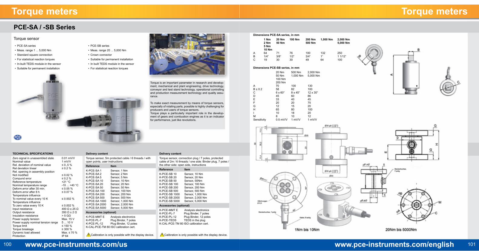
Dimensions PCE-SA series, in mm 1 Nm 20 Nm 100 Nm 200 Nm 1,000 Nm 2,000 Nm 2 Nm 50 Nm 500 Nm 5,000 Nm 5 Nm 10 Nm A 64 71 76 100 132 250B 1/4“ 3/8“ 1/2“ 3/4“ 1“ 1 1/12“C 19 30 30 49 64 100
Dimensions PCE-SB series, in mm 20 Nm 500 Nm 2,000 Nm 50 Nm 1,000 Nm 5,000 Nm 100 Nm 200 Nm A 70 100 130B ± 0.2 58 82 100C 6 x 60° 8 x 45° 12 x 30°D 45 60 86E 33 40 45F 20 20 75G 12 15 20H 65 80 100I 10 18 20M 8 10 12Sensitivity 0.5 mV/V 1 mV/V 1 mV/V
TECHNICAL SPECIFICATIONSZero signal in unassembled state 0.01 mV/VNominal value 1 mV/VRel. deviation of nominal value ≤ 0.,5 %Rel deviation linear ≤ 0.2 %Rel. opening in assembly position Not modified ≤ 0.02 %Compund error ≤ 0.2 %Reference temperature +21 °CNominal temperature range -10 ... +40 °CDeform.error after 30 min. ≤ 0.05 % Deform.error after 8 h ≤ 0.07 %Temperature influence To nominal value every 10 K ≤ 0.002 %Temperature influence To zero value every 10 K ≤ 0.002 % Input resistance 400 Ω ± 25 ΩOutput resistance 350 Ω ± 2 ΩInsulation resistance > 5 GΩPower supply tension Max. 15 VPower supply nominal tension range 5 ... 10 VTorque limit ≤ 150 %Torque breakage ≥ 300 %Dynamic load allowed Max. ≤ 70 %Protection IP 64
Delivery contentTorque sensor, 5m protected cable / 6 threads / with open points, user instructionsReference Item K-PCE-SA 1 Sensor, 1 Nm K-PCE-SA 2 Sensor, 2 Nm K-PCE-SA 5 Sensor, 5 Nm K-PCE-SA 10 Sensor, 10 Nm K-PCE-SA 20 Sensor, 20 Nm K-PCE-SA 50 Sensor, 50 Nm K-PCE-SA 100 Sensor, 100 Nm K-PCE-SA 200 Sensor, 200 Nm K-PCE-SA 500 Sensor, 500 Nm K-PCE-SA 1000 Sensor, 1,000 Nm K-PCE-SA 2000 Sensor, 2,000 Nm K-PCE-SA 5000 Sensor, 5,000 Nm Accessories (optional) K-PCE-MMT E Analysis electronics K-PCE-PL-7 Plug Binder, 7 poles K-PCE-PL-12 Plug Binder, 12 poles K-CAL-PCE-TM 80 ISO calibration cert.
Calibration is only possible with the display device.
Delivery contentTorque sensor, connection plug / 7 poles, protected cable of 2m / 6 threads / one side: Binder plug, 7 poles / the other side: open side, instructionsReference Item K-PCE-SB 10 Sensor, 10 Nm K-PCE-SB 20 Sensor, 20 Nm K-PCE-SB 50 Sensor, 50Nm K-PCE-SB 100 Sensor, 100 Nm K-PCE-SB 200 Sensor, 200 Nm K-PCE-SB 500 Sensor, 500 Nm K-PCE-SB 1000 Sensor, 1,000 Nm K-PCE-SB 2000 Sensor, 2,000 Nm K-PCE-SB 5000 Sensor, 5,000 Nm Accessories (optional) K-PCE-MMT E Analysis electronics K-PCE-PL-7 Plug Binder, 7 poles K-PCE-PL-12 Plug Binder, 12 poles K-PCE-TEDS TEDS in the plug K-CAL-PCE-TM 80 ISO calibration cert.
Calibration is only possible with the display device.
Torque meters Torque metersPCE-SA / -SB SeriesTorque sensor• PCE-SA series• Meas. range 1 ... 5,000 Nm• Standard square connection• For statistical reaction torques • In-built TEDS module-in the sensor• Suitable for permanent installation
• PCE-SB series• Meas. range 20 ... 5,000 Nm• Crown connector• Suitable for permanent installation• In built TEDS module in the sensor• For statistical reaction torques
Torque is an important parameter in research and develop-ment, mechanical and plant engineering, drive technology, conveyor and test stand technology, operational controlling and production measurement technology and quality assu-rance.
To make exact measurement by means of torque sensors, especially of rotating parts, possible is highly challenging for producers and users of torque sensors.Torque plays a particularly important role in the develop-ment of gears and combustion engines as it is an indicator for performance, just like revolutions.