for vehicle owner's manual - linquist · ceiver equipment (such as cb, walkie-talkie, ham...
TRANSCRIPT

Owner's Manualfor Vehicle

325Ci330Ci

Foreword
Congratulations, and thank you for choosing a BMW.
Thorough familiarity with your vehicle will provide you with enhanced control and security when you drive it. Therefore we have one request:
Please take the time to read this Owner's Manual and familiarize yourself with the information that we have compiled for you before starting off in your new BMW. The manual contains important data and instructions intended to assist you in obtaining maximum satisfaction from your BMW's unique array of advanced technical features. It also contains information on vehicle maintenance designed to enhance operating safety while simultaneously helping you to maintain your BMW's value throughout an extended service life. For additional information refer to the supple-mental manuals.
This Owner's Manual should be considered a permanent part of this vehicle. It should stay with the vehicle when sold to provide the next owner with important operating, safety and maintenance information.
This manual is supplemented by a Service and Warranty Information Booklet (US models) or a Warranty and Service Guide Booklet (Canadian models). We recommend that you read this publication thoroughly.
Your BMW is covered by the following warranties:
– New Vehicle Limited Warranty
– Limited Rust Perforation Warranty
– Federal Emissions System Defect Warranty
– Federal Emissions Performance Warranty
– California Emission Control System Limited Warranty
Detailed descriptions of these warranties are provided in the Service and Warranty Information Booklet (US models) or in the Warranty and Service Guide Booklet (Canadian models).
We wish you an enjoyable driving experience.
BMW AG

Contents
Ove
rvie
w
Cockpit 14Instrument cluIndicator and Multifunction s
(MFL) 21Hazard warninRefueling 22Fuel specificaTire inflation p
Rollover protection system 61
es Opening and closing:
Vehicle Memory, Key Memory 63
Driving:Ignition lock 64Starting the engine 64Switching off the engine 65Parking brake 66Manual transmission 66Automatic transmission with
Steptronic 67Indicator/Headlamp flasher 69Washer/Wiper system/
Rain sensor 70Cruise control 72
Everything under control:Odometer 74
Adjustments:Correct sitting posture 48Seats 48
Tachometer 74Energy control 74Fuel gauge 75Temperature gauge 75Service Interval Display 75Check Control 76Computer 76
Technology for safety and driving convenience:Park Distance Control (PDC) 79Automatic Stability Control plus
Traction (ASC+T) 80
Contents
(bleached without chlorine, suitable for recycling).
Co
ntr
ols
an
d f
eat
urster 15
warning lamps 17teering wheel
g triangle 22
tions 23ressures 24
Keys 28Central locking system 28Opening and closing
– via the remote control 29– via the door lock 31– from the inside 32
Luggage compartment lid 33Luggage compartment 35Alarm system 36Electric power windows 38Manual convertible top 39Fully-automatic convertible
top 42Wind deflector 46
© 2001 Bayerische Motoren WerkeAktiengesellschaftMunich, GermanyReprinting, including excerpts, only with the written consent of BMW AG, Munich. Order No. 01 41 0 156 190US English VIII/01Printed in GermanyPrinted on environmentally friendly paper
Adjusting electric power seats 49
Lumbar support 50Head restraints 50Entering the rear 51Safety belts 52Seat and mirror memory 53Seat heating 54Steering wheel 54Mirrors 55
Passenger safety systems:Airbags 56Transporting children safely 59

5n
w
In the engine compartment:
Hood 118
ure
s
nc
eDynamic Stability Control (DSC) 81
Special operating instructions:Break-in procedures 108
Over
vie
Cont
rols
Mai
nten
ance
Engine compartment essentials 119
Washer fluids 120Engine oil 121Coolant 123Brake fluid 124
Maintenance:The BMW Maintenance
System 125
Laws and regulations:Technical modifications 126California Proposition
65 Warning 126OBD interface socket 127
Interior conveniences:Glove compartment 96BMW Universal Transmitter 97
Repa
irs
Data
Inde
x
Co
ntr
ols
an
d f
eat
Op
era
tio
n, m
ain
ten
aTire Pressure Monitor (RDC) 83Flat Tire Monitor 85
Lamps:Parking lamps/Low beams 87Instrument lighting 88High beams/Standing lamps 88Fog lamps 88Interior lamps 89
Controlling the climate for pleasant driving:Air conditioning 90Automatic climate control 93
Driving notes 109Antilock Brake System
(ABS) 109Brake system 109Hardtop 110
Wheels and tires:Tire inflation pressure 113Tire condition 113Tire replacement 114Wheel and tire
combinations 116Winter tires 116
Storage compartments 99Cellular phone 100Ashtray, front 100Ashtray, rear 101
Loading and transporting:Ski bag 102Cargo loading 103Roof-mounted luggage rack for
the hardtop 105
Contents
ex
Everything from A to Z 150
es taReplacement procedures: Engine data 144Ind
Ow
ne
r se
rvic
e p
roc
ed
ur
Te
ch
nic
al d
aOnboard tool kit 130Windshield wiper blades 130Lamps and bulbs 130Changing a wheel 135Battery 139Fuses 139
Assistance, giving and receiving:Jump-starting 140Towing the vehicle 141
Dimensions 145Weights 146Capacities 147


8n
Notes on the O
We have made ethat you are ablein this Owner's Mpossible. The fasspecific topics isindex at the end.only an initial oveyou will find this iThe detailed tablintended to stimuencourage you tothe manual.
Should you wish some time in the
Your individual vehicle
On purchasing your BMW, you have decided in favor of a model with individ-ualized equipment and features. This Owner's Manual describes all models and equipment that BMW offers within the same group.
We hope you will understand that equipment and features are included that you might not have chosen for your vehicle. You can easily identify any differences with the aid of the asterisk
*
used to identify all optional equipment and accessories.
If your BMW features equipment which
wner's Manualvery effort to ensure to find what you need anual as quickly as test way to find by using the detailed If you wish to gain rview of your vehicle, n the first chapter.e of contents is late your interest and read the remainder of
to sell your BMW at future, please d over this Owner's
Symbols usedIndicates precautions that must be followed precisely in order to
avoid the possibility of personal injury and serious damage to the vehicle.<
Contains information that will assist you in gaining the optimum
benefit from your vehicle and enable you to care more effectively for your vehicle.<
Refers to measures that can be taken to help protect the
environment.<
is not described in this Owner's Manual (car radio or telephone, for instance), supplementary Owner's Manuals are enclosed. We ask you to read these manuals as well.
remember to hanManual to the new owner; it is legal part of the vehicle.
If you have any additional questions, your BMW center will be glad to advise you.
< Marks the end of a specific item of information.
* Indicates special equipment, country-specific equipment and optional extras.
Identifies systems or components, which can either be activated or
adapted to suit an individual driver's requirements (Vehicle Memory, Key Memory), refer to page 62.Remember that activation and adjust-ments on some of these systems can only be performed at your BMW center.<
NotesSymbolsYour individual vehicle
Status at timeBMW pursues aongoing developensure that our embody the higstandards combstate-of-the-art reason, it is posdescribed in thisdiffer from thosecan errors and oruled out. You aappreciate that recognized on tillustrations or dOwner's Manua
9n
Over
view
Cont
rols
nanc
e
of printing policy of continuous, ment conceived to
vehicles continue to hest quality and safety ined with advanced, technology. For this sible that the features Owner's Manual could on your vehicle. Nor missions be entirely re therefore asked to no legal claims can be
Mai
nte
Repa
irs
Data
he basis of the data, escriptions in this l.
Inde
x
Status at time of printingFor your own safety

10n
For your own saUse unleadecontaining u
10 % ethanol or oup to 2.8% oxyge15 % MTBE or 3%equivalent amounnot void the appliccovering defects imanship. Field excated significant dquality (volatility, ctives, for exampleoffered for sale in Canada. The use may result in drivestalling problems,certain environmeas high ambient tealtitude.Should you encoulems which you surelated to the fuelrecommend that yswitching to a recbrand.Failure to comply mendations may rmaintenance.Obey all applicablhandling gasoline
dar detectors, components, brake nes (including
table cellular phone le without using an
antenna) or trans-ch as CB, walkie-
similar) may cause the vehicle, ty, interfere with al system or affect W Limited
our BMW center for
fetyd gasoline only. Fuels p to and including ther oxygenates with n by weight (i.e. methanol plus an
t of co-solvent) will able warranties
n materials or work-perience has indi-ifferences in fuel omposition, addi-
) among gasolines
Important safety information!
For your own safety, use genuine parts and accessories approved by BMW.
When you purchase accessories tested and approved by BMW and Original BMW Parts, you simultaneously acquire the assurance that they have been thor-oughly tested by BMW to ensure optimum performance when installed on your vehicle.
BMW warrants these parts to be free
radios, amplifiers, rawheels, suspension dust shields, telephooperation of any porfrom within the vehicexternally mounted ceiver equipment (sutalkie, ham radio or extensive damage tocompromise its safethe vehicle's electricthe validity of the BMWarranty. Contact y
n.
mote control to e compartment
he vehicle. Refer to more details.<
eplacement, or ission control may be performed pair establishment
ny certified auto-
e parts ou should consult ction of this
the United States and of poor-quality fuels ability, starting and especially under ntal conditions, such mperature and high
nter driveability prob-spect could be
you are using, we ou respond by ognized high-quality
with these recom-esult in unscheduled
from defects in material and workman-ship.
BMW will not accept any liability for damage resulting from installation of parts and accessories not approved by BMW.
BMW cannot test every product on the market to determine whether it can be used on a BMW safely and without risk to either the vehicle, its operation, or its occupants.
Original BMW Parts, BMW Accessories and other products approved by BMW, together with professional advice on using these items, are available from all BMW centers.
additional informatio
Do not use key or relock doors or luggagwith anyone inside tpages 29 and 31 for
Maintenance, rrepair of the em
devices and systemsby any automotive reor individual using amotive part.<
Symbol on vehiclIndicates that ythe relevant se
e safety rules when .< Installation and operation of non-BMW
approved accessories such as alarms,
Owner's Manual for information on a particular part or assembly.

The following
REPORTIN
If you believeimmediately iNorth Americ
If NHTSA recgroup of vehividual proble
To contact NWashington, also obtain o
11n
Over
view
Cont
rols
nanc
e
th, you should ing BMW of
000.
ct exists in a
applies only to vehicles owned and operated in the US.
G SAFETY DEFECTS
that your vehicle has a defect which could cause a crash or could cause injury or deanform the National Highway Traffic Safety Administration (NHTSA) in addition to notifya, LLC., P.O. Box 1227, Westwood, New Jersey 07675-1227, Telephone (201) 307-4
eives similar complaints, it may open an investigation, and if it finds that a safety defe
Mai
nte
Repa
irs
Data
volved in indi-
-0123 in0590. You can
cles, it may order a recall and remedy campaign. However, NHTSA cannot become inms between you, your dealer, or BMW of North America, LLC.
HTSA, you may either call the Auto Safety Hotline toll-free at 1-800-424-9393 (or 366D.C. area) or write to: NHTSA, U.S. Department of Transportation, Washington, D.C. 2ther information about motor vehicle safety from the Hotline.
Inde
x
12n

13n
Over
view
Cont
rols
aint
enan
ce
Overview
Controls and features
Operation, maintenance
MRe
pair
sDa
tade
x
Owner service procedures
Index
Technical data
In
Overview

14n
Cockpit
eams 87
rs 69
69
3 Wiper/Washer system/Rain sensor 70
4 Hazard warning flashers
5 Central locking system 28
ar window defroster 91, 95
orn: the entire surface
justing the steering wheel 54
g lamps 88
1 Parking lamps/Low b
2 > Turn signal indicato> Standing lamps 88> High beams 88> Headlamp flasher> Computer 76
6 Re
7 H
8 Ad
9 Fo
15n
Over
view
Cont
rols
Mai
nten
ance
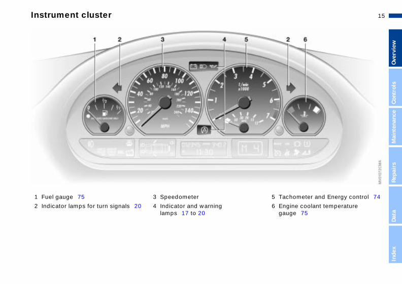
Instrument cluster
Repa
irs
Data
Inde
x
turn signals 20
3 Speedometer
4 Indicator and warning lamps 17 to 20
Tachometer and Energy control 74
Engine coolant temperature gauge 75
1 Fuel gauge 75
2 Indicator lamps for
5
6

16n
Instrument cluster
to zero 74
ontrol 76
10 Display for
>
Trip odometer/Odometer 74
>
Clock 76
>
Service Interval 75
>
Computer 76
lector lever and program display r automatic transmission 18, 69
ontrol button for the clock 76
dicator and warning
11 Sefo
12 C
13 In
mps 17 to 20 la7 Indicator and warninglamps 17 to 20
8 Reset trip odometer
9 Indicator for Check C

17n
Over
view
Cont
rols
Mai
nten
ance
Repa
irs
ta
Indicator and warning lamps
Brake warning lamp
●
If the lamp comes on when the parking brake is not engaged:
ck the brake fluid level. Before ing further, be sure to comply with instructions on pages 109 and 124
Brake warning lamp for Cana-dian models.
Tire Pressure Monitor (RDC)/Flat Tire Monitor
●
In addition, an acoustic signal is nded: a tire failure has occurred. uce vehicle speed immediately and the vehicle. Avoid hard brake lications. As you steer the vehicle, caution to avoid overcorrecting. additional information refer to es 83, 85
p di-
elt is
<
chedrivthe
souRedstopappuseForpag
DaIn
dex
Technology that monitors itself The system runs an operational check on the indicator and warning lamps identified with the ● symbol each time you switch on the ignition. They each light up once for different periods of time.
If a fault should occur in one of these systems, the corresponding lamp does not go out after the engine is started, or it lights up while the vehicle is moving. You will see how to react in the following section.
Red: stop immediatelyBattery charge current ●The battery is no longer beingcharged. Indicates a defective
alternator drive belt or a problem withthe alternator's charge circuit. Pleasecontact the nearest BMW center.
If the drive belt is defective, stoand switch off the engine imme
ately to prevent overheating and serious engine damage. If the drive bis defective, increased steering effortalso required.<
Engine oil pressure ●Stop the vehicle immediately
and switch off the engine.Check the engine oil level; top off as required. If the oil level is correct: please contact the nearest BMW center.
Do not continue driving, as the engine could sustain serious
damage from inadequate lubrication.
18n
Indicator and warning lamps
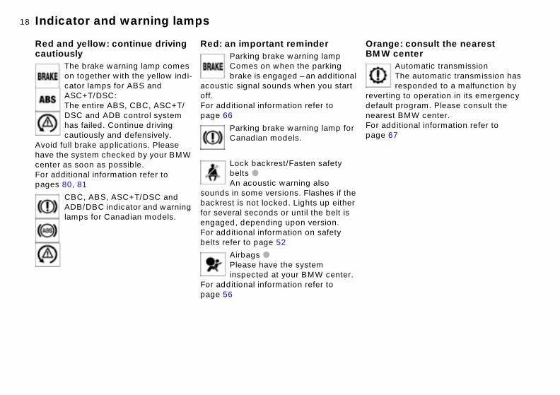
ge: consult the nearest center
Automatic transmissionThe automatic transmission has responded to a malfunction by
ing to operation in its emergency lt program. Please consult the st BMW center.ditional information refer to
67
l
OranBMW
revertdefauneareFor adpage
Red and yellow: continue driving cautiously
The brake warning lamp comes on together with the yellow indi-cator lamps for ABS and ASC+T/DSC:The entire ABS, CBC, ASC+T/DSC and ADB control system has failed. Continue driving cautiously and defensively.
Avoid full brake applications. Please have the system checked by your BMW center as soon as possible.For additional information refer to pages 80, 81
CBC, ABS, ASC+T/DSC and
Red: an important reminderParking brake warning lampComes on when the parking brake is engaged – an additiona
acoustic signal sounds when you start off. For additional information refer to page 66
Parking brake warning lamp forCanadian models.
Lock backrest/Fasten safety belts ●
An acoustic warning also sounds in some versions. Flashes if the
ADB/DBC indicator and warning lamps for Canadian models.
backrest is not locked. Lights up eitherfor several seconds or until the belt is engaged, depending upon version.For additional information on safety belts refer to page 52
Airbags ●Please have the system inspected at your BMW center.
For additional information refer to page 56

19n
Over
view
Cont
rols
Mai
nten
ance
Repa
irs
ta
Indicator and warning lamps
Automatic Stability Control plus Traction (ASC+T)/Dynamic Stability Control (DSC) indicator lamp and brake warning lamp
●
The indicator lamps remain on: the DSC
and ADB/DBC have n switched off with the button or are ctive.se consult the nearest BMW
ter. additional information refer to e 81
DSC and ADB indicator and warning lamps for Canadian models.
Dynamic Brake Control (DBC)
●
Malfunction in DBC system. Conventional braking efficiency
vailable and unrestricted.e the system repaired by your BMW ter. additional information refer to e 82
.r
,
us
e
e as l. of
beedefePleacenForpag
is aHavcenForpag
DaIn
dex
Yellow: check as soon as possibleAntilock Brake System (ABS) ●ABS has been deactivated in response to system malfunction.
Conventional braking performance remains available with no loss of effi-ciency. Please have the system inspected at your BMW center.For additional information refer to page 109
ABS warning lamp for Canadian models.
Engine oil levelComes on during driving: the engine oil level has fallen to the
Brake pads ●Have the brake pads checkedFor additional information refe
to page 109
Tire Pressure Monitor (RDC)/Flat Tire Monitor ●Check tire inflation pressures
refer to pages 24, 83, 85
Automatic Stability Control plTraction (ASC+T)/Dynamic Stability Control (DSC) ●
Indicator lamp flashes:The system is actively regulating drivtorque and braking force.The indicator lamp stays lit:ASC+T has been switched off with th
absolute minimum; refill as soon as possible. Do not drive more than approx. 30 miles (50 km) until you do.For additional information refer to page 121
Engine oil levelComes on after the engine has been switched off: add engine
oil at the earliest opportunity (next time you stop to refuel).For additional information refer to page 121
button or it is defective, or the DSC hbeen switched off, ADB is operationaPlease contact a BMW center in casea malfunction.Additional information beginning on page 80

20n
Indicator and warning lamps
: for your information
High beamsComes on when the high beams are on or the headlamp flasher
uated.ditional information refer to 69, 88
Blue
is actFor adpages
Add washer fluidThe washer fluid is too low. Top off the fluid at the earliest
opportunity. For additional information refer to page 120
SERVICE ENGINE SOON ●If the indicator lamp comes on either continuously or intermit-
tently, this indicates a fault in the emis-sions-related electronic systems. Although the vehicle remains opera-tional, you should have the systems checked at your BMW center at the earliest possible opportunity. For addi-tional information refer to page 127
SERVICE ENGINE SOON
Green: for your informationTurn signal indicatorFlashes when the turn signal is operated.
Rapid flashing indicates a system malfunction.For additional information refer to page 69
Cruise controlLights up when the cruise control is activated: available for
operation via the multifunction steeringwheel.For additional information refer to page 72
warning lamp for Canadian models.
Engine electronics ●There is a fault in the electronic engine-management system.
You can continue to drive with reduced engine output or engine speed. Please have the system inspected at your BMW center.
Add coolantThe coolant level is too low. Add coolant at the earliest opportu-
nity. For additional information refer to page 123
Fog lampsLights up whenever you switch on the fog lamps.
For additional information refer to page 88

21n
Over
view
Cont
rols
Mai
nten
ance
Repa
irs
Data
Multifunction steering wheel (MFL)
*
me
ise control: select a stored setting.
ise control: store and accelerate (+) ecelerate and store (–).
ise control: activate/interrupt/deac-te.
te
ndn
n
t
Volu
Cru
Cruor d
Crutiva
Inde
x
The buttons integrated in the multifunc-tion steering wheel (MFL) are provided so that you can operate a number of accessories quickly and without being distracted from traffic conditions. You may operate:
> Selected radio functions> The cruise control> Selected cellular phone functions.
The controls are active only when the corresponding systems and
accessories are switched on.<
Press briefly:
Switch between phone, radio, cassetand CD.
Forward:
> RadioPress briefly: station scan in FM baExtended pressure: search functio
> CDPress briefly: jump to next trackExtended pressure: search functioin track
> CassettePress briefly: stop track scan or fas
Receive a phone call, initiate dialing, terminate a call.
forwardExtended pressure: fast forward
> PhoneScan personal phone book.
Rewind/reverse: functions as fast forward.

22n
Hazard warning triangle
*
Refueling
Always observe all safety precau-tions posted at the service station handling fuel. carry spare fuel containers in ehicle. Whether empty or full, containers can leak, cause an sion, or lead to fire in the event of ision.
<
whenNeveryour vtheseexploa coll
:
The hazard warning triangle is stored in the luggage compartment lid inside the container for the onboard tools.
To open the container, loosen the wing
Fuel filler doorAlways switch off the engine before refueling, as it is not
possible to add fuel with the engine
nut.Always observe all legal regula-tions requiring a warning triangle
to be carried in the vehicle.<
running, and attempts may also triggerthe SERVICE ENGINE SOON lamp.<
Press on the rear edge of the fuel filler door to open and close it.
If an electrical malfunction occurs, youcan unlock the fuel filler door manually
1. Unlock the trim panel on the right side of the luggage compartment
2. Pull the button with the fuel pump symbol.

23n
Over
view
Cont
rols
Mai
nten
ance
Refueling Fuel specifications
engine uses lead-free gasoline .
uired fuel:
remium Unleaded Gasoline, in. 91 AKI. KI = Anti Knock Index
Never use leaded fuel, as it would cause permanent and irreversible
age to the oxygen sensor and the lytic converter.<
e pt
r . e
or
Theonly
Req
> PmA
damcata
Repa
irs
Data
Inde
x
Simple and environmentally friendly
Open the filler cap carefully to prevent fuel from spraying out.
Refill early to avoid damaging thcatalytic converter; never attem
to drive to the last drop of fuel in the tank.<
Close the fuel cap carefully afterefueling until a "click" is heard.
While closing, be sure not to squeezethe strap which is fastened to the capA loose or missing cap will activate thmessage CHECK FILLER CAP lamp the SERVICE ENGINE SOON lamp.<
Tank capacity: approx. 16.6 gal. (63 liters), incl. a reserve capacity of approx. 2.1 gal. (8 liters).
Fuel spray may cause injury.<
Keep the filler cap in the bracket (arrow) attached to the fuel filler door.
When refueling, insert the filler nozzle completely into the filler pipe. Pulling the nozzle out of the pipe during refu-eling
> results in premature pump shutoff> and will reduce the effectiveness of
the vapor recovery system on the pump.
As long as the filler nozzle is used prop-erly, the fuel tank is full whenever the nozzle shuts off the first time.

24nTire inflation pressures
ply with tire approval ificationsflation pressures in the table
to BMW approved tire sizes and anufacturers. Your BMW center is ar with these pressures. Higher ures may be specified for tires by other manufacturers.
vehicle is equipped with tires that ly meet US standards, but also ean standards. We recommend clusive use of BMW approved
-
ComspecThe inapplytire mfamilipressmade
Your not onEuropthe extires.
The specified inflation pressures areprovided on a sticker attached to the B-pillar and visible with the driver's door open.
Check the tire pressures on a regular basis – at least twice a
month – and before every extended journey. Otherwise, incorrect tire pres-sure can lead to poor handling, to tire damage and accidents.Remember to check the inflation pres-sure in the space-saver or standard spare tire. Inflate the spare tire to the highest inflation pressure of any tire on your vehicle.<
Checking tire pressuresAll pressures are specified in the stan-dard units of pressure for your country, psi or kilopascal, and apply to cold tires (tires at ambient temperature, refer to tire pressure table on the following page).
Vehicles with Tire Pressure Monitor (RDC)/Flat Tire Monitor: after correcting the inflation pressures, reactivate the system, refer to pages 83, 85.
Another instruction plate regarding inflation pressures on the door pillar indicates which system is equipped on your vehicle.
25n
Over
view
Cont
rols
Mai
nten
ance
Tire inflation pressures
(250) 44 (300)
(250)–
–44 (300)
225/45 R 17 91 Q M+S
(270) 46 (320)
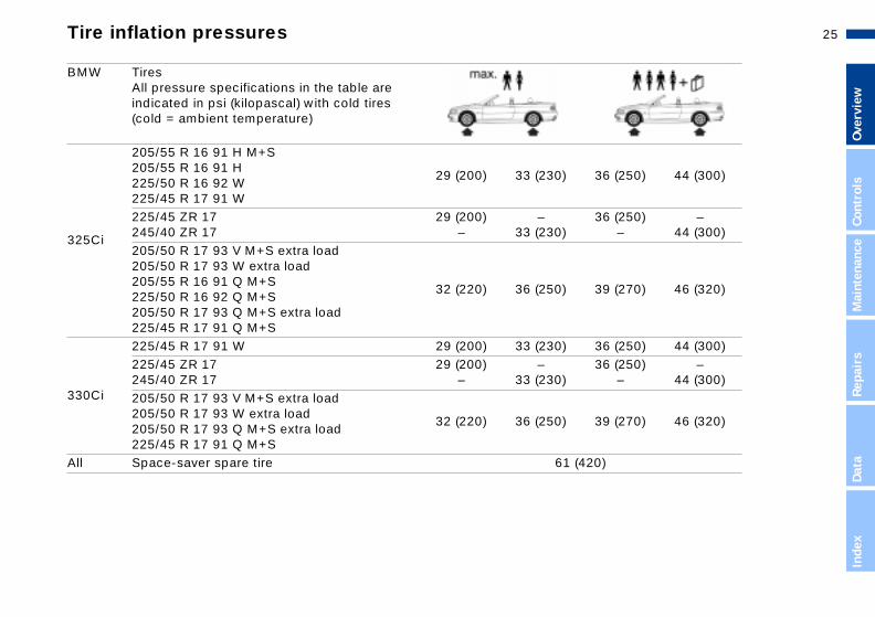
330Ci
225/45 R 17 91 W 29 (200) 33 (23225/45 ZR 17245/40 ZR 17
29 (200)–
–33 (23
205/50 R 17 93 V M+S extra load205/50 R 17 93 W extra load205/50 R 17 93 Q M+S extra load225/45 R 17 91 Q M+S
32 (220) 36 (25
All Space-saver spare tire
0) 36
0)36
0) 39
Repa
irs
Data
Inde
x
(250) 44 (300) (250)–
–44 (300)
(270) 46 (320)
0) 36
0)36
0) 39
61 (420)
BMW TiresAll pressure specifications in the table are indicated in psi (kilopascal) with cold tires (cold = ambient temperature)
325Ci
205/55 R 16 91 H M+S205/55 R 16 91 H225/50 R 16 92 W225/45 R 17 91 W
29 (200) 33 (23
225/45 ZR 17245/40 ZR 17
29 (200)–
–33 (23
205/50 R 17 93 V M+S extra load205/50 R 17 93 W extra load205/55 R 16 91 Q M+S225/50 R 16 92 Q M+S205/50 R 17 93 Q M+S extra load
32 (220) 36 (25

26n

27n
Over
view
Cont
rols
e
Overview
and features
maintenance
Controls
Operation,
Mai
nten
anc
Repa
irs
Data
Inde
x
Owner service procedures
Index
Technical data

28nKeys Central locking system
onceptentral locking system is ready for tion whenever the driver's door is d. The system engages and es the locks on the
rsage compartment lid
l filler doorve compartment.
entral locking system can be ted
outside via the remote control ell as via the driver's door lock inside by pressing a button.
ting it from inside does not lock
,
The cThe coperaclosereleas
> doo> lugg> fue> glo
The copera
> fromas w
> from
Activa
el filler door, refer to page 32. the system is actuated from the e, the anti-theft system is acti- simultaneously. Both the door and release handles remain d. The alarm system is also armed armed.ed from the inside, the central g system unlocks automatically in ent of an accident, except on that have been locked individu-ing the lock buttons, refer to
32. In addition, the hazard ng flashers and interior lamps on.
the fuWhenoutsidvatedlocks lockeor dis
If locklockinthe evdoorsally uspage warnicome
The key set1 Master keys with remote control
determine the functions of the Key Memory, refer to page 63. You can
2 Spare key for storage in a safe placesuch as in your wallet. This key is notintended for constant use
3 Door and ignition keyThe locks for the luggage compart-ment lid and the glove compartment cannot be operated with this key – this is useful for valet parking, for example.
mark individual keys for subsequent identification by applying the colored decals that you received when accepting delivery of your vehicle
Each master key is equipped with an extended-life battery. This
battery is recharged in the ignition lock during normal operation. For this reason, if you have a master key that is not in regular use you should use that keys approx. once a year while driving for an extended period to charge the battery, refer also to page 29.<
29n
Over
view
Cont
rols
Mai
nten
ance
Repa
irs
Data
ex
Opening and closing – via the remote control
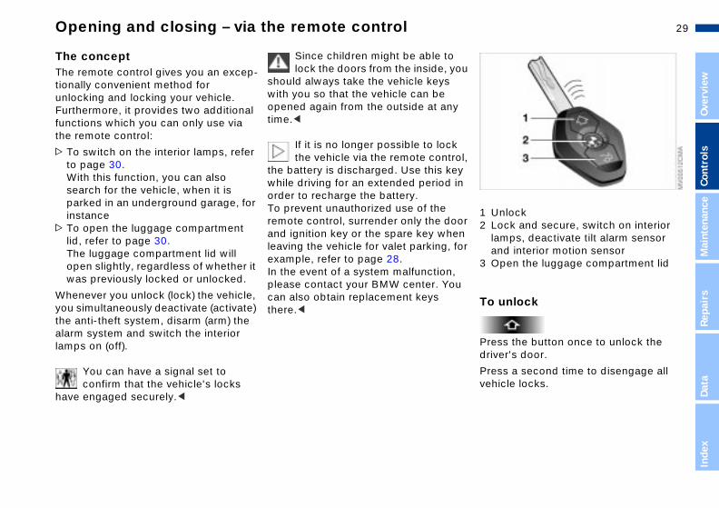
nlockock and secure, switch on interior mps, deactivate tilt alarm sensor nd interior motion sensorpen the luggage compartment lid
unlock
ss the button once to unlock the er's door.
ss a second time to disengage all icle locks.
ou
ol, y in
or n or
u
1 U2 L
laa
3 O
To
Predriv
Preveh
Ind
The conceptThe remote control gives you an excep-tionally convenient method for unlocking and locking your vehicle. Furthermore, it provides two additional functions which you can only use via the remote control:
> To switch on the interior lamps, refer to page 30.With this function, you can also search for the vehicle, when it is parked in an underground garage, for instance
> To open the luggage compartment lid, refer to page 30.The luggage compartment lid will
Since children might be able tolock the doors from the inside, y
should always take the vehicle keys with you so that the vehicle can be opened again from the outside at anytime.<
If it is no longer possible to lockthe vehicle via the remote contr
the battery is discharged. Use this kewhile driving for an extended period order to recharge the battery.To prevent unauthorized use of the remote control, surrender only the doand ignition key or the spare key wheleaving the vehicle for valet parking, fexample, refer to page 28.
open slightly, regardless of whether it was previously locked or unlocked.
Whenever you unlock (lock) the vehicle, you simultaneously deactivate (activate) the anti-theft system, disarm (arm) the alarm system and switch the interior lamps on (off).
You can have a signal set to confirm that the vehicle's locks
have engaged securely.<
In the event of a system malfunction,please contact your BMW center. Yocan also obtain replacement keys there.<

30nOpening and closing – via the remote control
S owners onlyansmitter and receiver units ly with part 15 of the FCC (Federal unication Commission) regula-
Operation is governed by the ing:
D: LX8EWSLX8FZVSLX8FZVE
liance statement: evice complies with part 15 of the ules. Operation is subject to the
ing two conditions:
device may not cause harmful rference, and device must accept any interfer-e received, including interference t may cause undesired operation.
Any unauthorized modifications to these devices could void the authority to operate the equip-<
For UThe trcompCommtions.follow
FCC I
CompThis dFCC Rfollow
> Thisinte
> thisenctha
user'sment.
To lock and secure
Press the button.
Do not lock the vehicle if there are passengers still inside, because
they would not be able to unlock the doors.<
To switch on the interior lamps
With the vehicle locked, press the button.
To open the luggage compartment lid
Press the button.
The luggage compartment lid will openslightly, regardless of whether it was previously locked or unlocked.
Before and after a trip, be sure that the luggage compartment lid
has not been opened unintentionally.<
Panic mode (trigger alarm)
To switch off the tilt alarm sensor* and interior motion sensor*
Press the button a second time imme-diately after locking.For additional information refer to page 37.
Provided that the alarm system is armed, you can respond to imminent danger by holding down the button for between two and five seconds. Press the button to cancel the alarm.
External systemsThe remote control system's operationmay be affected by other units or equipment operating in the immediate vicinity of your vehicle.
If this should occur, you can still open and close the vehicle using the master key in either the door or luggage compartment lid locks.

31n
Over
view
Cont
rols
Mai
nten
ance
Repa
irs
Data
Inde
x
Opening and closing – via the door lock
nual operation he event of electrical malfunction)
n the key to the extreme left or right nlock/lock the driver's door.
d
d
-
Ma(in t
Turto u
One turn of the key in the driver's door lock unlocks the driver's door only. Turning the key a second time unlocks all of the remaining doors, the luggage compartment lid and the fuel filler door.
Convenience operationYou can also operate the power windows and the fully-automatic convertible top via the door lock.
> To open: with the door closed, holthe key in the "Unlock" position
> To close: with the door closed, holthe key in the "Lock" position.
Watch the closing process carefully and be sure that no one is
trapped by the closing motion. Releasing the key stops the opera-tion.<
Do not lock the vehicle if there are passengers still inside, because
they would not be able to unlock the doors.<
You can have a signal set to confirm that the vehicle's locks
have engaged securely.<

32nOpening and closing – from the inside
ck the doorser use the central locking button
ock both doors at once
ss down the individual door lock tons. The fuel filler door remains cked. To prevent the driver from
ng inadvertently locked out of the icle, the driver's door lock button not engage as long as the door is n.
Since children might be able to lock the doors from the inside, you d always take the vehicle's keys ou so that you can open the le again from the outside at any
To lo> Eith
to lor
> prebutunlobeivehwillope
shoulwith yvehictime.<
You can use this button to control the central locking system whenever the doors are closed. The doors and luggage compartment lid are unlocked
To unlock and open the doors> Either unlock the doors together with
the button for the central locking system and then pull each of the release handles above the armrests or
> pull the release handle for each doortwice: the first pull unlocks the door,and the second one opens it.
or locked only. The anti-theft system is not activated.
If only the driver's door was unlocked from the outside and
you press the button, then, with the driver's door still open, the passenger-side door, the luggage compartment lid and the fuel filler door will unlock, too. If the driver's door is closed, it will be locked.<
The central locking system can be locked automatically as soon as
you begin to drive if you desire. This can be adjusted to be key-specific.<

33n
Over
view
Cont
rols
Mai
nten
ance
Repa
irs
Data
Inde
x
Luggage compartment lid
open from the inside*e luggage compartment lid has not n locked separately, you can open it this button in the footwell on the er's side when the vehicle is ionary.
d.
)
ll
To If thbeewithdrivstat
The lockOnly the master keys fit in the lock of the luggage compartment lid, refer to page 28.
To open from the outsidePress the button in the handle recess(arrow): the luggage compartment lidopens slightly.
To secure separatelyLock the glove compartment using the master key.
This locks the luggage compartment lid and disconnects it from the central locking system. This feature can be used to prevent unauthorized access to the luggage compartment when you hand over the door and ignition key for valet parking, for instance, refer to page 28.
The luggage compartment is lit whenthe luggage compartment lid is opene
Manual operation(in the event of electrical malfunction
Turn the master key all the way to theleft – the luggage compartment lid wiopen slightly.
The luggage compartment is locked again as soon as you close the lid.

34nLuggage compartment lid
gency releaseever releases the luggage artment lid from the luggage artment's interior.
EmerThis lcompcomp
To closeThe handle recesses in the interior trim panel of the luggage compartment lid
Operate the vehicle only when theluggage compartment lid is
closed. Otherwise, exhaust fumes could penetrate into the interior of the vehicle. Should it be absolutely neces-sary to operate the vehicle with the luggage compartment lid open (with closed convertible top):> Close all windows> Turn up the blower to increase the air
supply from the air conditioning or automatic climate control, refer to page 90 or 93.<
(arrows) make it easier to pull the lid down.
To avoid injuries, be sure that the travel path of the luggage
compartment lid is clear when closing it, following the same precautions as with all closing procedures.<

35n
Over
view
Cont
rols
Mai
nten
ance
s
Luggage compartment
enlarge the luggage partment
h the convertible top closed, you enlarge the luggage compartment. o this, flip the handle outward and
ss it down and toward the front of vehicle (arrow). The convertible top
y p-
its
To comWitcanTo dprethe
Repa
irDa
taIn
dex
compartment panel is now raised and secured.
et ready to open the convertible , follow the steps in reverse order.
Before lowering the convertible top, always check to ensure that
luggage compartment panel has rned to its original position, refer to e 40 or 43. Attempts to lower the with the panel folded up can lead to icle damage.<
To gtop
the retupagtopveh
Lift the floor panel up and hook it1. Press the button (arrow)2. Grab it by the handle and pull up
3. Raise and secure the floor panel busing the fitting on the weatherstriping on the drip rail (arrow) to suspend it.
Carefully replace the hanger in holder when lowering the floor
panel back into place.<

36nLuggage compartment Alarm system*
m and disarm the alarm m the vehicle is locked or unlocked e driver's door lock or with the e control, the alarm system is also aneously armed or disarmed.
You can have different acknowl-edgment signals set to confirm g and disarming.<
an open the luggage compart-lid even when the system is by pressing the button on the
:
To arsysteWhenvia thremotsimult
armin
You cment armed
e control, refer to page 30. When losed, the lid is once again ed.
remotit is csecur
The fittings at the corners of the luggage compartment provide you with a convenient means of attaching luggage nets* and flexible straps for securing luggage.
Refer also to Cargo loading on page 103.
The conceptThe vehicle alarm system responds:
>When a door, the hood or the luggage compartment lid is opened
> To movements inside the vehicle (interior motion sensor)
> To variations in the vehicle's tilt anglesuch as those occurring during attempts to steal the wheels or tow the vehicle
> To interruption of battery voltage.
The system responds to unauthorized vehicle entry and attempted theft by simultaneously activating the following
> The acoustic alarm sounds for
30 seconds> The hazard warning flashers are acti-vated for approx. five minutes
> The high beams flash on and off in rhythm with the hazard warning flashers.

37n
Over
view
Cont
rols
Mai
nten
ance
Alarm system*
rior motion sensorctivate the interior motion sensor r to Avoiding unintentional alarms e previous column) if children or als are to remain in the vehicle.
US owners only transmitter and receiver units ply with part 15 of the FCC (Federal munication Commission) regula-
s. Operation is governed by the wing:
ID: LTQSDR2G5
pliance statement: device complies with part 15 of the Rules. Operation is subject to the
he
.
on e
se s
InteDea(refein thanim
ForThecomComtionfollo
FCC
ComThisFCC
Repa
irs
Data
Inde
x
wing two conditions:
his device may not cause harmful terference, andis device must accept any interfer-
nce received, including interference at may cause undesired operation.
Any unauthorized modifications to these devices could void the
r's authority to operate the equip-t.<
r
d rm r is
follo
> Tin
> theth
usemen
Indicator lamp displays> The indicator lamp below the interior
rearview mirror flashes continuously:the system is armed
> The indicator lamp flashes for 10 seconds when the system is disarmed: an attempted entry has been detected in the period since tsystem was armed.
Following triggering of an alarm, the indicator lamp will flash continuously
Avoiding unintentional alarmsThe tilt alarm sensor and interior motisensor may be switched off at the samtime. You can do this to prevent a falalarm from being triggered in garagewith elevator ramps, for instance, or when the vehicle is transported by trailer or train:
> The indicator lamp flashes during arming: the door(s), the hood or the luggage compartment lid are not completely closed. Even if you do not close the alerted area(s), the remaining areas are secured, and the indicator lamp will flash continuously after 10 seconds. However, the inte-rior motion sensor is not activated
> The indicator lamp goes out when the system is disarmed: no manipulation or attempted intrusions have been detected in the period since the system was armed
Lock the vehicle twice (= arm the system). Press the button on the remote control twice in succession olock the vehicle twice with the key.The indicator lamp lights up briefly anthen flashes continuously. The tilt alasensor and the interior motion sensoare deactivated as long as the systemarmed.

38nElectric power windows
the ignition has been switched off:an still use the electric power ws for up to 15 minutes, as long one opens any of the front doors.
When leaving the vehicle, always remove the ignition key from the nd remember to close the doors vent children from operating the r windows and injuring them-, etc.<
nvenience closing via the door efer to page 31.
After You cwindoas no
lock ato prepoweselves
For colock r
-
To open and close windowFrom ignition key position 1:
> Press the switch up to the pressure
To operate all the side windows> Press the switch up to the pressure
point: the windows retract as long as
point: the window retracts as long as you maintain pressure on the switch
> Press the switch briefly past the pres-sure point (only on driver's door): the window moves automatically. Pressing the switch again stops the opening cycle.
You can close the window in the same manner by pulling the switch.
you maintain pressure on the switch> Press the switch briefly past the pres
sure point: the windows move auto-matically. Pressing the switch again stops the opening cycle.
You can close all windows in the samemanner by pulling the switch.
39n
Over
view
Cont
rols
Mai
nten
ance
pair
s
Manual convertible top
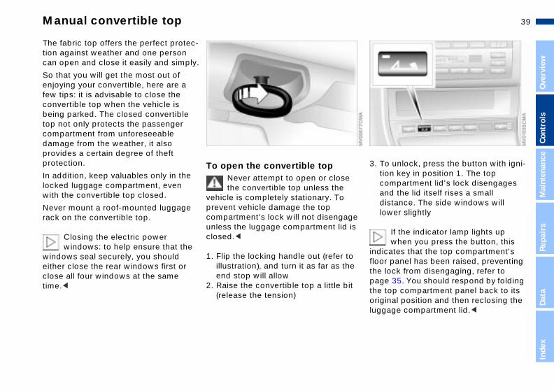
o unlock, press the button with igni-on key in position 1. The top ompartment lid's lock disengages nd the lid itself rises a small istance. The side windows will wer slightly
If the indicator lamp lights up
e s
3. Tticadlo
ReDa
taIn
dex
when you press the button, this cates that the top compartment's r panel has been raised, preventing lock from disengaging, refer to e 35. You should respond by folding top compartment panel back to its inal position and then reclosing the age compartment lid.<
e
t
indifloothe pagthe origlugg
The fabric top offers the perfect protec-tion against weather and one person can open and close it easily and simply.
So that you will get the most out of enjoying your convertible, here are a few tips: it is advisable to close the convertible top when the vehicle is being parked. The closed convertible top not only protects the passenger compartment from unforeseeable damage from the weather, it also provides a certain degree of theft protection.
In addition, keep valuables only in the locked luggage compartment, even with the convertible top closed.
To open the convertible topNever attempt to open or closethe convertible top unless the
vehicle is completely stationary. To
Never mount a roof-mounted luggage rack on the convertible top.Closing the electric power windows: to help ensure that the
windows seal securely, you should either close the rear windows first or close all four windows at the same time.<
prevent vehicle damage the top compartment's lock will not disengagunless the luggage compartment lid iclosed.<
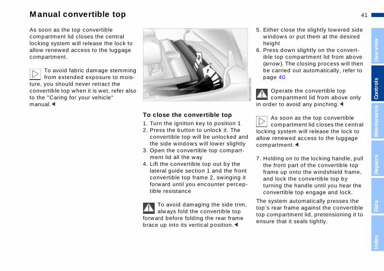
1. Flip the locking handle out (refer toillustration), and turn it as far as thend stop will allow
2. Raise the convertible top a little bi(release the tension)

40nManual convertible top
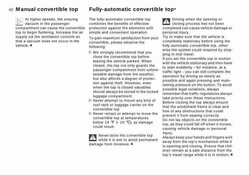
ss down slightly on the convert- top compartment lid from above ow). The closing process will then carried out automaticallyer close the slightly lowered side dows or put them at the desired ght.
1
8. Preible(arrbe
9. Eithwinhei
To prevent finger injuries, always grip the convertible top compart-lid from above.erlock device helps avoid damage vehicle by preventing the ge compartment lid from opening s the convertible top compartment ompletely closed.<
ment An intto theluggaunleslid is c
4. Position the rear convertible top frame vertically and grip it firmly
You can make it easier to raise the
5. Reach into the recess created whenthe convertible top compartment is lifted and pull it all the way by hand
6. Lay the rear convertible top frame in
rear convertible top frame bypressing the area indicated by the arrow.<
the convertible top compartment 2
Let go of the rear convertible top frame before laying the convert-
ible top down, otherwise, the side trim panel could be damaged.<
7. Raise the front of the top and pull it back for storage
Now finish pushing the convertibletop all the way down into the
convertible top compartment. This makes it easier to close the convertibletop compartment lid, especially at lower temperatures.<
41n
Over
view
Cont
rols
Mai
nten
ance
pair
s
Manual convertible top
ither close the slightly lowered side indows or put them at the desired eightress down slightly on the convert-le top compartment lid from above rrow). The closing process will then e carried out automatically, refer to age 40
Operate the convertible top compartment lid from above only
rder to avoid any pinching.<
As soon as the top convertible compartment lid closes the central
ing system will release the lock to w renewed access to the luggage partment.<
olding on to the locking handle, pull e front part of the convertible top
d y
5. Ewh
6. Pib(abp
in o
lockallocom
7. Hth
ReDa
taIn
dex
frame up onto the windshield frame, and lock the convertible top by turning the handle until you hear the onvertible top engage and lock.
system automatically presses the 's rear frame against the convertible compartment lid, pretensioning it to ure that it seals tightly.
,
c
Thetoptopens
As soon as the top convertible compartment lid closes the central locking system will release the lock to allow renewed access to the luggage compartment.
To avoid fabric damage stemming from extended exposure to mois-
ture, you should never retract the convertible top when it is wet, refer also to the "Caring for your vehicle" manual.<
To close the convertible top1. Turn the ignition key to position 12. Press the button to unlock it. The
convertible top will be unlocked an
the side windows will lower slightl3. Open the convertible top compart-ment lid all the way
4. Lift the convertible top out by the lateral guide section 1 and the front convertible top frame 2, swinging it forward until you encounter percep-tible resistance
To avoid damaging the side trimalways fold the convertible top
forward before folding the rear framebrace up into its vertical position.<
42nManual convertible top Fully-automatic convertible top*
Driving when the opening or closing process has not been leted can cause vehicle damage or nal injury. make sure that the vehicle is letely stationary before using the utomatic convertible top, other-he system could respond by stop-n mid-travel. set the convertible top in motion e vehicle stationary and then have
rt suddenly – for instance, at a light – you can still complete the tion by driving as slowly as ble and again pressing and main-g pressure on the button. To avoid
-
comppersoTry tocompfully-awise tping iIf youwith thto statrafficoperapossitainin
ble legal violations, always ber that traffic regulations always
riority over these instructions.e closing the top always ensure e windshield frame is clear and f any obstructions that could nt it from seating correctly.t lay objects on the convertible s they could fall off when it moves, g vehicle damage or personal
.s keep your hands and fingers well from the top's mechanism while it ning and closing. Ensure that chil-emain at a safe distance from the travel range while it is in motion.<
possirememtake pBeforthat thfree opreveDo notop, acausininjuryAlwayaway is opedren rtop's
At higher speeds, the ensuing vacuum in the passenger
compartment can cause the convertible top to begin fluttering. Increase the air supply via the ventilation controls so that a vacuum does not occur in the vehicle.<
The fully-automatic convertible top combines the benefits of effective protection against the elements with simple and convenient operation.
To gain maximum satisfaction from yourconvertible, please observe the following:
>We strongly recommend that you close the convertible top before leaving the vehicle parked. When closed, the top not only guards the passenger compartment from unforeseeable damage from the weather, but also affords a degree of protec-tion against theft. However, even when the top is closed valuables
should always be stored in the lockedluggage compartment> Never attempt to mount any kind of roof rack or luggage carrier on the convertible top
> Never retract or attempt to move theconvertible top at temperatures below 14 7 (– 10 6), as damage could result.
Never store the convertible top while it is wet to avoid permanent
damage from moisture.<

43n
Over
view
Cont
rols
Mai
nten
ance
Repa
irs
Data
Fully-automatic convertible top*
aintain pressure on the corre-ponding button for the convertible p operation. The red indicator lamp
ashes whenever the convertible top echanism is in operation. It goes ut when the opening or closing rocess has been completed. it continues flashing after the ontrol button is released, the rocess has not completed opening r closing. The operation can be esumed in the desired direction by ressing the button again. the yellow indicator lamp lights up ontinuously with the button ressed, the convertible top ompartment panel has been raised nd the top cannot be moved, refer step 2.
The convertible top stops moving immediately when the button is
ased. You can resume operation in desired direction by pressing the on again.<
n ng off.
ng
,
4. MstoflmopIfcporpIfcpcato
relethe butt
Inde
x
When closing the electric power windows while underway, always
remember to either start by closing the rear windows or to close all of them at once. Failure to adhere to this sequence can prevent the windows from sealing tightly at high speeds.<
At higher speeds, the ensuing vacuum in the passenger
compartment can cause the convertible top to begin fluttering. Increase the air supply via the ventilation controls so that a vacuum does not occur in the vehicle.<
1 Close
2 Open
To open and close
From ignition key position 1 and withthe vehicle stationary.To avoid placing unnecessary loads othe battery, you should avoid operatithe top when the engine is switched
1. Read and comply with the precedisafety precautions
2. Before opening the convertible topensure that the convertible top compartment panel is back down into its original position, refer to page 35
3. Ensure that the luggage compart-ment lid is closed
44nFully-automatic convertible top*
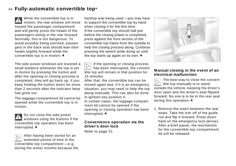
al closing in the event of an rical malfunctionThe best way to close the convert-ible top manually is to stand e the vehicle, keeping the driver's pen and the driver's seat flipped
rd. No one is to be in the rear seat this operation.<
move the insert between the rear ts. Take the trim off of the guide
-
Manuelect
outsiddoor oforwaduring
1. Resea
rod and flip it forward. Press down hard on the emergency lock (arrow). After a brief pause, the mechanismthe convertible top compartment will be released
for lid
While the convertible top is in motion, the rear window will move
toward the passenger compartment and will gently press the heads of the passengers sitting in the rear forward. Normally, this is not dangerous. To avoid possibly being pinched, passen-gers in the back seat should lean their heads slightly forward while the convertible top is in motion.<
The side power windows are lowered a small distance whenever the top is set in motion by pressing the button and after the opening or closing process is completed, they will go back up, if you
hardtop was being used — you may haveto support the convertible top by hand when closing it for the first time: If the convertible top should halt just before the closing phase is completed, press against the front section of the convertible top frame from the outside tohelp the closing process along. Continuepressing the switch while doing so until the top starts up again on its own.<
If the opening or closing process has been interrupted, the convert
ible top will remain in that position for 15 minutes.After that, the convertible top can be
keep holding the button down for more than 2 seconds after the indicator lamp has gone out.
The luggage compartment lid cannot be opened while the convertible top is in motion.
Do not close the side power windows using the buttons if the
convertible top operation has been interrupted.<
After having been stored for an extended period of time in the
convertible top compartment — e.g. during the winter months because the
moved again and, if it is an emergencysituation, you may need to help the topalong manually. This can also be done in ignition key position 0.In certain cases, the luggage compart-ment lid cannot be opened if the opening or closing operation has beeninterrupted.<
Convenience operation via the driver's door lockRefer to page 31.

45n
Over
view
Cont
rols
Mai
nten
ance
Repa
irs
Fully-automatic convertible top*
se a screwdriver to lift out the cover anel that is in the center of the front onvertible top framesert the Allen wrench (stored next the emergency lock; refer to
age 44) in the 6-point socket rrow)ull down on the front convertible p frame as far as possible. omplete the closing process by ontinuing to turn the wrench to the
op
ng d
lip n-
4. Upc
5. Intop(a
6. PtoCc
Data
Inde
x
ft. Turn until the front convertible p frame has locked onto the wind-
hield frame. The system automati-ally presses the top's rear frame gainst the convertible top compart-ent lid, pretensioning it to ensure at it seals tightly.
letoscamth
If the mechanism for the convert-ible top compartment lid does not
unlock, then insert the Allen wrench 1 into the recess 2 and turn clockwise to release it
2. If the luggage compartment lid is closed, open the convertible top compartment lid up as far as the stwill allow
3. Lift out the convertible top by holdi
on to the lateral guide section 1 anthe front convertible top frame 2. Position the rear convertible top frame vertically and close the convertible top compartment lid. Fthe rear convertible top frame dowward
46nFully-automatic convertible top* Wind deflector*
he convertible top open, the wind tor keeps air movement in the nger compartment to a minimum, roviding you with a pleasant
even at higher speeds. The wind tor comes in a protective sleeve, ecause of its slim dimensions, can sily stored in the luggage artment.
llatione the wind deflector out of its tective sleeve
With tdeflecpassethus pdrive,deflecand bbe eacomp
Insta1. Tak
pro
Please consult your BMW center to have the defect corrected.<
In the event of an electrical malfunction, never open the
convertible top manually. The convert-ible top compartment lid cannot be locked, and would open while you are driving.<

47n
Over
view
Cont
rols
Mai
nten
ance
Repa
irs
Wind deflector
Operate the convertible top compartment lid from above only
rder to avoid any pinching.h the wind deflector in place: to id damaging the wind deflector er push the front seats all the way k.<
ovalow the same procedure as when alling, just reverse the steps.
t
he o d
t-
d
in oWitavonevbac
RemFollinst
Data
Inde
x
-
is of.
2. Flip out both sides and lock into place. It is essential for the two components marked in the illustra-tion (arrows) to mesh at this point
3. Hold the wind deflector so that thesmaller half points toward the fronand guide the mounting pin for theside piece into the proper opening
4. Pull back on the mounting pin for t
other side piece by using a slide, sthat the mounting pin can be guideinto the opening provided5. Unlock the convertible top comparment lid via the convertible top control button, refer to page 43, anopen the convertible top compart-ment lid
6. Flip the back half of the wind deflector backward, so that the mounts are lying on the vehicle
7. Close the convertible top compartment lid via the convertible top control button. The wind deflectornow attached so that it is theft-pro

48nCorrect sitting posture Seats
adjusting your seat, always rve the following precautionsNever try to adjust your seat while operating the vehicle. The seat respond with unexpected move- and the ensuing loss of vehicle l could lead to an accident. Never ith the backrest reclined to an e horizontal angle (important for assengers to remember). Keep ckrest relatively upright to mini-
the risk of sliding under the safety nd sustaining injury in an acci-
adjustment
l
Whenobse
couldment,controride wextremfront pthe bamize belt adent.<
Seat
er seat, refer to page 49d restraint, refer to page 50ering the rear, refer to page 51
> Pow> Hea> Ent
For relaxed and fatigue-free driving you should select a sitting position that reflects your personal requirements. Correct posture combines with safety belts and airbags to enhance occupant safety in the event of an accident. To ensure that the vehicle's safety systems provide you with optimal protection, we request that you direct your careful attention to the following section.
For supplementary information on transporting children refer to page 59.
Sitting correctly with airbagsAlways maintain an adequate distance between yourself and the
Safe with safety beltsNever allow more than one personto wear a single safety belt. Never
allow infants or small children to ride ina passenger's lap. Avoid twisting the belt while routing it firmly across the hips and shoulder, wear it as snugly against your body as possible. Do not allow the belt to rest against hard or fragile objects. Do not route the belt across your neck, or run it across sharpedges. Be sure that the belt does not become caught or jammed. Avoid wearing bulky clothing and pull on the lap belt periodically to retension it overyour shoulders. In the event of a fronta
airbags. Always hold the steering wheel by the rim to keep any chance of injury to hands or arms to an absolute minimum should the airbag be deployed. Never allow any objects, individuals or animals to obstruct the areas between passengers and airbags.Never use the front airbag's cover as a storage tray or support for objects of any kind. Never allow front passengers to rest their feet or legs on the airbag cover.<
For airbag locations and additional information on airbags refer to page 56.
impact, a loose lap belt could slide overyour hips, leading to abdominal injury. In addition, the safety belt's restraint effectiveness is reduced if it is worn loosely. Expectant mothers should always wear their safety belts, taking care to position the lap belt against thelower hips, where it will not exert pres-sure against the abdominal area.<
For information on using the safety belts refer to page 52.
49n
Over
view
Cont
rols
Mai
nten
ance
Repa
irs
Adjusting electric power seats
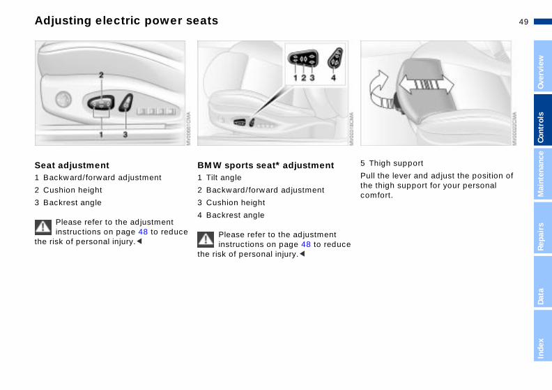
h support
e lever and adjust the position of igh support for your personal rt.
5 Thig
Pull ththe thcomfo
Data
Inde
x
Seat adjustment1 Backward/forward adjustment
2 Cushion height
BMW sports seat* adjustment1 Tilt angle
2 Backward/forward adjustment
3 Backrest angle
Please refer to the adjustment instructions on page 48 to reduce
the risk of personal injury.<
3 Cushion height
4 Backrest angle
Please refer to the adjustment instructions on page 48 to reduce
the risk of personal injury.<

50nLumbar support* Head restraints
angle
on the head restraints manually in eferred position.
2 Tilt
Positithe pr
AdjustmentYou can adjust the backrest's contour for additional support in the curvature
Front head restraints1 Height
Head restraints reduce the risk of
of your spine's lumbar region.The upper hips and spinal column receive supplementary support to help you maintain a relaxed, upright posture.
> Press the front/rear of the switch: increase/decrease curvature
> Press the upper/lower end of the switch: increase the upper/lower curvature.
spinal injury in the event of an accident.Adjust the head restraint so that its center is approximately at the height ofyour ears.When moving the head restraints up ordown, avoid placing hands and fingersbetween the head restraint and the upper edge of the backrest to avoid thepossibility of injury.<
51n
Over
view
Cont
rols
Mai
nten
ance
Head restraints Entering the rear
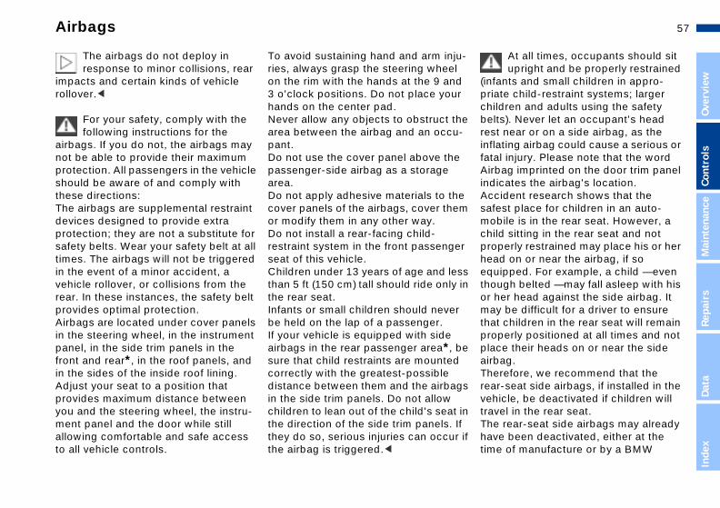
seat-integrated safety belt system allows for easy access to the rear.
ift lever 1 up and tilt the backrest rward
ar
e
lt
ll-r. ut
he
TheSGS
1. Lfo
Repa
irs
Data
Inde
x
ress and hold button 2 in driving irection until the seat moves to the esired positionfter entering the rear, fold back and ck the backrest
ress button 2 opposite the direction f travel and hold. The seat moves ack into its previous position. If the utton 2 is released beforehand, the eat stops in the respective position.
2. Pdd
3. Alo
4 Pobbs
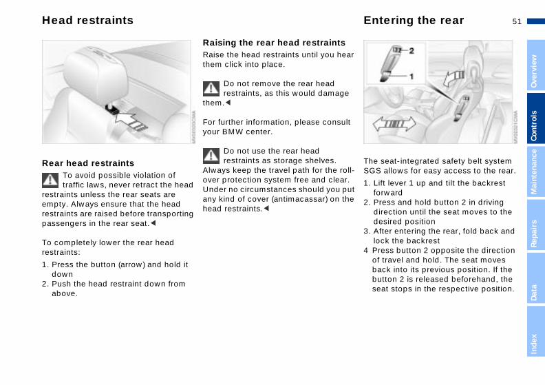
Rear head restraintsTo avoid possible violation of traffic laws, never retract the head
restraints unless the rear seats are
Raising the rear head restraintsRaise the head restraints until you hethem click into place.
Do not remove the rear head restraints, as this would damag
them.<
For further information, please consuyour BMW center.
Do not use the rear head restraints as storage shelves.
Always keep the travel path for the roover protection system free and cleaUnder no circumstances should you pany kind of cover (antimacassar) on t
empty. Always ensure that the head restraints are raised before transporting passengers in the rear seat.<
To completely lower the rear head restraints:
1. Press the button (arrow) and hold it down
2. Push the head restraint down from above.
head restraints.<

52nEntering the rear Safety belts
Always detach the rear safety belts from their retainers before ng.<
To avoid undesired movement at high speeds, always store the rear belts in their retainers when they t in use.<
If the safety belt system has been subjected to the stresses involved accident or otherwise damaged: the entire safety belt mechanism ed by your BMW center. In addi-ave your BMW center inspect the belt anchors. Failure to observe
weari
safetyare no
in an have replaction, hsafety
recaution can prevent the safety from providing the intended level tection.<
this pbelts of pro
You can lock a backrest that has been tilted forward. This makes
sense when, for instance, someone is climbing into the rear on an incline. To do this, press against the backrest until you hear it click into place. To move it back into place, you do not need to first unlock it by moving the lever 1.<
Lock both backrests while driving, otherwise there is a danger of an
unexpected movement causing an accident.<
The indicator lamp in the instrument cluster will flash to alert you that the
Always wear your safety beltAlways fasten your safety belt before starting off. As supplemental restraint
backrest is not locked in place, refer to page 18.
devices, the airbags are designed to enhance the effectiveness of the safetybelts, and not to replace them.
To closeMake sure you hear the lock engage inthe belt buckle.
To open1. Press the red button in the belt
buckle2. Hold the belt3. Guide the belt back into its reel.
The safety belt system will automati-cally adapt to your body contours.

53n
Over
view
Cont
rols
Mai
nten
ance
Seat and mirror memory*
You can have this feature programmed so that when you
the remote control from your sonalized key to unlock your door, r seat, head restraint and exterior ors will all move into your own ferred positions.<
Before activating the programmed adjustment feature ensure that the
well behind the driver's seat is ty and unobstructed. If you fail to o, persons or objects could be
red or damaged if the seat should e backward.<
n u
3,
-
useperyoumirrpre
footempdo sinjumov
Repa
irs
Data
Inde
x
n
You can store and recall three different driver's seat and exterior mirror posi-tions.
The head restraint setting is
To select a stored settingDo not select a memory positiowhile the vehicle is moving. If yo
do so, there is a risk of accident fromunexpected seat movement.<
Ignition key in position 1:
> Briefly press memory button 1, 2 oras desired.Movement stops immediately whenone of the seat-adjustment or memory buttons is activated duringthe adjustment process.
With the driver's door closed and theignition key either removed or in position 0 or 2:
stored in memory, but the lumbar support is not.<
To store1. Ignition key position 1 or 22. Select the desired seat, head
restraint and exterior mirror positions3. Press the MEMORY button: the indi-
cator lamp in the button lights up4. Press memory button 1, 2 or 3, as
desired: indicator lamp goes out.
>Maintain pressure on the desired memory button (1, 2 or 3) until the adjustment process is completed.
If you press the MEMORY buttoaccidentally: press the button
again; the indicator lamp goes out.<

54nSeat and mirror memory* Seat heating** Steering wheel
stmenth the locking lever downward
just the steering column's rake reach to suit your seat position
Adju1. Pus2. Ad
and
l the lever back in.Never adjust the steering wheel while the vehicle is moving, other-ou run the risk of an accident due xpected movement.<
3. Pul
wise yto une
Passenger-side exterior mirror tilt function(Automatic curb monitor*)
The seat cushion and backrest can be heated with the ignition key in position 2.
You can select different heating modes
1. Move the mirror selector switch 1 to the "driver's mirror" position2. When the selector lever is placed in "Reverse," the passenger-side mirror tilts downward. This allows the driver to see the area directly adjacent to the vehicle during parking (curbs, etc.).
You can deactivate this automatic feature by setting the mirror selection switch to the "passenger side" position.
by repeatedly pressing the buttons.
You can also switch the higher heatingmodes off directly:Press the button and hold it slightly longer.

55n
Over
view
Cont
rols
Mai
nten
ance
Mirrors
rior rearview mirror educe glare from vehicles behind when you are driving at night, tilt mirror by turning the button.
u-
de ex e
es
InteTo ryouthe
Repa
irs
Data
Inde
x
icles without alarm system: the small lever forward.
is
i-
VehTilt
To adjust exterior mirrors1 Switch for 4-way adjustment2 Selection switch for changing
between mirrors
To adjust manuallyThe mirrors can also be adjusted manally:
Press the edge of the lens.Storing mirror settings, refer to Seat and mirror memory on page 53.
The mirror on the passenger's sifeatures a lens with a more conv
surface than the mirror installed on thdriver's side. When estimating the distance between yourself and othertraffic, bear in mind that the objects reflected in the mirror are closer thanthey appear. This means that estimatof the distance to following traffic
should not be regarded as precise. Thprecaution also applies to the non-spherical outer section of the lens.<Electric defrostingBoth mirrors are automatically heatedwhen you turn the ignition key to postion 2.

56nMirrors Airbags
ator lampThe indicator lamp displays the operational status of the airbag system from ignition key posi-
.
m operational:
indicator lamp comes on briefly n you turn the ignition key to ition 1 or higher.
m malfunction:
indicator lamp fails to go out r the engine has been started, or es on again during normal
ing.
Indic
tion 1
Syste
> Thewhepos
Syste
> Theaftecomdriv
e respond to any malfunctions in stem by immediately having it cted at your BMW center; other-he airbag could fail to respond to cident in which both the angle and verity of the impact would lly trigger airbag deployment.
The side airbags in the rear passenger area* of your vehicle lready have been deactivated at the time of manufacture or by a center. You may have them acti- if you desire to do so. Please ct your BMW center for additional ation.<
, .
Pleasthe syinspewise tan acthe senorma
may aeitherBMWvatedcontainform
Interior rearview mirror withautomatic dimming featureThis mirror automatically dims through
1 Front airbags on the driver and passenger sides
2 Side airbags on the driver and
an infinitely-variable range. It returns to its clear, undimmed mode whenever you engage reverse.To ensure that the mirror continues to operate efficiently, ensure that the photocells remain clear and unob-structed. One photocell is integrated in the mirror's lens (arrow), while the other is located at an offset position on the rear of the mirror. Refrain from attaching stickers to the windshield in the area immediately in front of the mirror.
passenger sides (front and rear*)
Protective effectThe front airbags supplement the safetybelts by providing additional protectionin the event of a severe frontal collisionin which the protection afforded by thebelts alone may no longer be sufficientThe head protection system and side airbags help provide protection in the event of a collision from the side. Eachof the side airbags is designed to help support the seat occupant's upper body.
For information on the correct sitting posture refer to page 48.
57n
Over
view
Cont
rols
Mai
nten
ance
Airbags
At all times, occupants should sit upright and be properly restrained
nts and small children in appro-te child-restraint systems; larger dren and adults using the safety s). Never let an occupant's head near or on a side airbag, as the ting airbag could cause a serious or l injury. Please note that the word ag imprinted on the door trim panel cates the airbag's location. ident research shows that the st place for children in an auto-ile is in the rear seat. However, a
d sitting in the rear seat and not perly restrained may place his or her d on or near the airbag, if so
u-l d r
he -
e m
r
(infapriachilbeltrestinflafataAirbindiAccsafemobchilprohea
Repa
irs
Data
Inde
x
ipped. For example, a child — even gh belted — may fall asleep with his er head against the side airbag. It be difficult for a driver to ensure children in the rear seat will remain perly positioned at all times and not e their heads on or near the side ag. refore, we recommend that the -seat side airbags, if installed in the icle, be deactivated if children will el in the rear seat. rear-seat side airbags may already e been deactivated, either at the of manufacture or by a BMW
ss in
r
be
gs
in If r if
equthouor hmaythatproplacairbTherearvehtravThehavtime
The airbags do not deploy in response to minor collisions, rear
impacts and certain kinds of vehicle rollover.<
For your safety, comply with the following instructions for the
airbags. If you do not, the airbags may not be able to provide their maximum protection. All passengers in the vehicle should be aware of and comply with these directions: The airbags are supplemental restraint devices designed to provide extra protection; they are not a substitute for safety belts. Wear your safety belt at all times. The airbags will not be triggered
To avoid sustaining hand and arm injries, always grasp the steering wheeon the rim with the hands at the 9 an3 o'clock positions. Do not place youhands on the center pad. Never allow any objects to obstruct tarea between the airbag and an occupant. Do not use the cover panel above thepassenger-side airbag as a storage area. Do not apply adhesive materials to thcover panels of the airbags, cover theor modify them in any other way. Do not install a rear-facing child-restraint system in the front passengeseat of this vehicle.
in the event of a minor accident, a vehicle rollover, or collisions from the rear. In these instances, the safety belt provides optimal protection. Airbags are located under cover panels in the steering wheel, in the instrument panel, in the side trim panels in the front and rear*, in the roof panels, and in the sides of the inside roof lining. Adjust your seat to a position that provides maximum distance between you and the steering wheel, the instru-ment panel and the door while still allowing comfortable and safe access to all vehicle controls.
Children under 13 years of age and lethan 5 ft (150 cm) tall should ride onlythe rear seat. Infants or small children should nevebe held on the lap of a passenger. If your vehicle is equipped with side airbags in the rear passenger area*, sure that child restraints are mountedcorrectly with the greatest-possible distance between them and the airbain the side trim panels. Do not allow children to lean out of the child's seatthe direction of the side trim panels. they do so, serious injuries can occuthe airbag is triggered.<

58nAirbags
the right way for a larger child to aring the seat belt when rear-side s (arrow) are provided.
This issit weairbag
center. Labels in the door opening should indicate the status of your rear- seat side airbags. If you are uncertain of their status, or wish to have the airbags activated or deactivated, please contact your BMW center.<
Even when all these guidelines are followed, there is still a small residual risk of injuries to the face, hands and arms occurring from airbag deployment in isolated instances. The ignition and inflation noise may provoke a mild temporary hearing loss in extremely sensitive individuals.
This is the right way for a child to sit in achild restraint when rear-side airbags (arrow) are provided.

59n
Over
view
Cont
rols
Mai
nten
ance
Repa
irs
Transporting children safely
mercially available child seats plying with the legal standard are
igned to be secured with a seat belt ith the seat belt portion of a combi-
on lap/shoulder belt. roperly or inadequately installed raint systems can increase the risk jury to children. Always read and w the instructions that come with
t n
Comcomdesor wnatiImprestof infollo
Data
Inde
x
system.
u use a child-restraint system with ther strap, three additional tether horage points (refer to the arrows in illustration) have been provided. ending on the location selected for ting in the rear passenger area, ch the tether strap to the corre-nding anchorage point to secure the d-restraint system. Remove the ter cover first.
the
If yoa teancthe Depseaattaspochilcen
LATCH child-restraint mounting system*The anchorage points for the child- restraint system are located behind the
To avoid undesired movement ahigher speeds, always store the
rear safety belts in their retainers whethey are not in use.<
upholstery at the positions indicated by the arrows.
Carefully slide the brackets through the gaps in the upholstery at the indicated locations.
Always follow all manufacturer's instructions and observe all safety
precautions when installing the LATCH child-restraint system.<
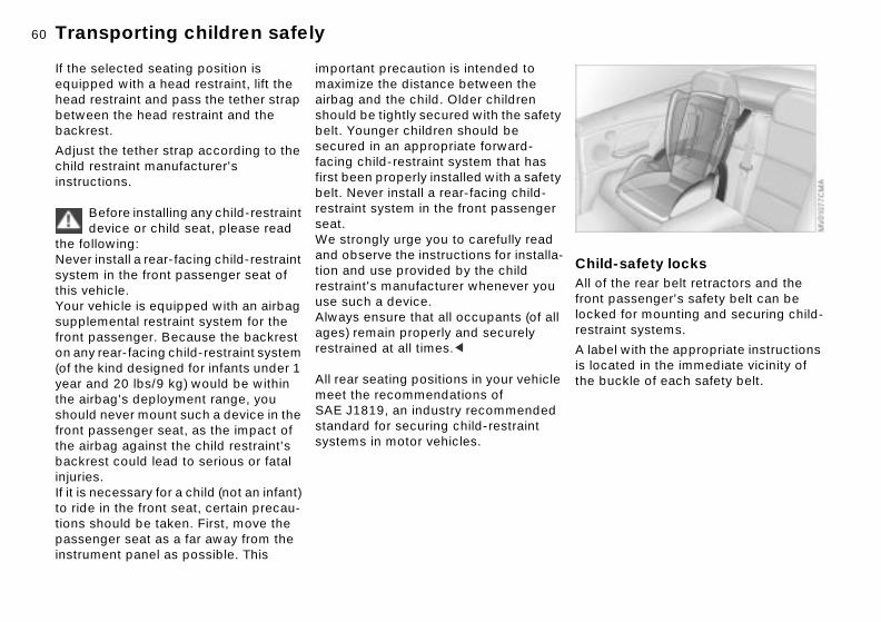
60nTransporting children safely
-safety locksthe rear belt retractors and the assenger's safety belt can be
d for mounting and securing child-int systems.
l with the appropriate instructions ted in the immediate vicinity of
-
ChildAll of front plockerestra
A labeis loca
the buckle of each safety belt.If the selected seating position is equipped with a head restraint, lift the head restraint and pass the tether strap between the head restraint and the backrest.
Adjust the tether strap according to the child restraint manufacturer's instructions.
Before installing any child-restraint device or child seat, please read
the following: Never install a rear-facing child-restraint system in the front passenger seat of this vehicle. Your vehicle is equipped with an airbag
important precaution is intended to maximize the distance between the airbag and the child. Older children should be tightly secured with the safetybelt. Younger children should be secured in an appropriate forward-facing child-restraint system that has first been properly installed with a safetybelt. Never install a rear-facing child-restraint system in the front passenger seat. We strongly urge you to carefully read and observe the instructions for installation and use provided by the child restraint's manufacturer whenever you use such a device.
supplemental restraint system for the front passenger. Because the backrest on any rear-facing child-restraint system (of the kind designed for infants under 1 year and 20 lbs/9 kg) would be within the airbag's deployment range, you should never mount such a device in the front passenger seat, as the impact of the airbag against the child restraint's backrest could lead to serious or fatal injuries. If it is necessary for a child (not an infant) to ride in the front seat, certain precau-tions should be taken. First, move the passenger seat as a far away from the instrument panel as possible. This
Always ensure that all occupants (of allages) remain properly and securely restrained at all times.<
All rear seating positions in your vehicle meet the recommendations of SAE J1819, an industry recommended standard for securing child-restraint systems in motor vehicles.

61n
Over
view
Cont
rols
Mai
nten
ance
Transporting children safely Rollover protection system
fter being automatically triggered, rotective function is not needed, the rollover protection system can
owered back into place. No special is needed for this.
e
, e ts
ar
le
he
,
If, aits pthenbe ltool
Repa
irs
Data
Inde
x
sing a screwdriver from the on-oard tool kit, remove the cover anel; to do this, position the screw-river under the notch (arrow)
i-
1. Ubpd
To lock the safety beltExtract the entire length of the belt from the inertia reel mechanism. Allow the reel to retract the belt somewhat and engage the buckle, then tighten the belt against the child-restraint system. The retraction mechanism is now locked. The belt cannot be extracted further. Always observe the installation instruc-tions provided by the manufacturer of the child-restraint system.
To release the safety beltRelease the safety belt, remove the child's seat and retract the safety belt to its end position on the belt retractor.
In the event of an accident or some other critical driving situation (extremtilting in the longitudinal or transverseaxis, loss of contact with the ground)the rollover protection system will beautomatically activated. The protectivbars located in the rear head restrainextend within fractions of a second.
In addition to the integrated rollover bin the windshield frame, the rollover protection system affords all the vehicoccupants necessary headroom.
Always keep the travel path for trollover protection system free
and clear. Under no circumstances should you cover the head restraints.
In the event of less serious accidentsthe safety belt will protect you and, depending on the severity of the accdent, so will the safety belt tensionerand the multi-stage airbag restraint system as well.<
62nRollover protection system
e same for the second protective you are not familiar with any of ocedures, consult your BMW r.
the rollover protection system ed out by your BMW center after been inadvertently triggered.
Do not move the convertible top under any circumstances if the er protection system has ded.t use the rear head restraints as e shelves.utely no modifications are to be to any of the rollover protection
's individual components or any wiring.our BMW center is to carry out ork on the rollover protection .
t
Do thbar. Ifthe prcente
Have checkit has
rollovextenDo nostoragAbsolmadesystemof its Only yany wsystem
Work done on the system that is carried out improperly could lead to failure inergency or accidental activation.ding having the system checked ure long-term operation: be scru-s in adhering to the Service al Display for maintenance inter-very 2 years at the latest, the roll-rotection system must be
cted at a BMW center.<
an emRegarto enspulouIntervvals. Eover pinspe
2. Pull up on the lever (arrow) toward the front of the vehicle and keep it in this position
3. Keep pressing down on the protec-tive bar 1 from on top until you hear iclick into place
4. Put the cover panel back in place
and press down firmly5. Press the rear part of the head restraint 2 to retract it.

63n
Over
view
Cont
rols
Mai
nten
ance
Repa
irs
Vehicle Memory, Key Memory
mples for Key Memory:
ocks the vehicle when you start off, fer to page 32utomatically adjusts the power seat nd exterior mirrors to your personal rogrammed settings when you nlock the vehicle, refer to page 53nlocks driver's door first, then roceeds to disengage the vehicle's maining locks, refer to page 29.
You will see this symbol through-out the Owner's Manual. It is to
ind you at appropriate places of the ings that are available to you.<
al
ith le
t le,
Exa
> Lre
> Aapu
> Upre
remsett
Data
Inde
x
e
ng
How the system functionsNo doubt you have reflected at one time or another on how great it would be if you could permanently configure
adjustment data for as many as four different individuals into the system.
The system then relies on a bilateral data exchange to identify the individuuser and dial in the selected settingswhenever the remote control unit is used to disengage the door locks.
Color-coded decals have been provided to help you distinguish indi-vidual keys with different settings.
What the system can doYour BMW center can provide you wdetails on the capabilities of the VehicMemory and Key Memory systems. Afew examples follow below:
your vehicle's various features and adjustments to mirror your own indi-vidual preferences. In engineering your vehicle, BMW has incorporated a number of options for personal adjust-ment that can be programmed into your vehicle at your BMW center.
The available configuration data fall into two categories, according to whether their primary orientation is the vehicle (Vehicle Memory) or the individual (Key Memory). Provided that each person has a separate remote-control key, you can have your BMW center enter
Examples for Vehicle Memory:
> Various signals as acknowledgmenwhen you lock or unlock your vehicrefer to pages 29, 31
> Activates/deactivates the "Follow mhome" lamp, refer to page 87
> Activates/deactivates daytime drivilamps, refer to page 87.

64nIgnition lock Starting the engine
re startingage the parking brakeure that the gearshift lever is in tral, or, with an automatic trans-sion, that the selector lever is in Press the clutch pedal at low peratures.
Do not allow the engine to run in enclosed spaces. The exhaust contain carbon monoxide, an ss and colorless, but highly toxic
hing the exhaust gases poses an e health risk, and can lead to
sciousness and death.
t
Befo> Eng> Ens
neumis
> Deptem
gasesodorlegas. Breatextremuncon
t leave the vehicle unattended he engine running. An unat-d vehicle with a running engine sents a potential safety hazard.<
When driving, standing at idle, and parking the vehicle, take care id contact between the hot st system and flammable mate-
grass, hay, leaves, etc.). Such ct could lead to a fire, resulting in s personal injury and property ge.<
not press the accelerator pedal le starting the engine.
Do nowith ttenderepre
to avoexhaurials (contaserioudama
> Do whi
0 Steering locked
1 Steering unlocked
2 Ignition on
Vehicles with manual transmis-sion:
Step on the clutch when starting the vehicle. A lockout prevents the engine from starting if the clutch is not depressed.<
Steering lockedThe key can only be inserted and removed in this position.
After removing the key, turn the steering wheel slightly to the left or righuntil you hear the lock engage.
The sound system remains operationalfor approx. 20 minutes after you switch
3 Start engine
Vehicles with automatic transmis-sion:
Do not move the selector lever from position "P" until the engine is running (ignition key position 2).Your vehicle is equipped with an inter-lock. Therefore, the ignition key cannot be turned to position 0 and removed until the selector lever is in position "P."<
off the ignition (ignition key in position 0or key removed). Simply switch it backon.
Steering unlocked You will find that it is often easier to turnthe ignition key from position 0 to posi-tion 1 when you move the steering wheel slightly to help disengage the lock.Individual electrical accessories are ready for operation.
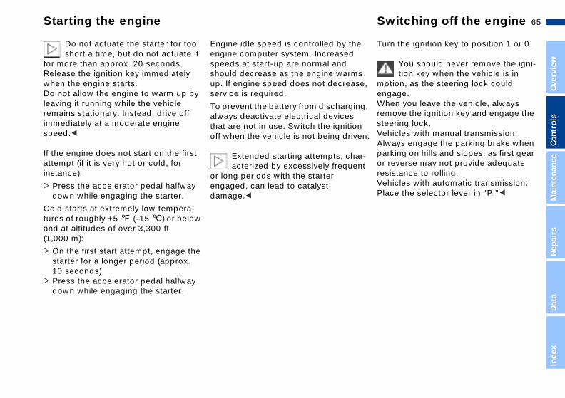
65n
Over
view
Cont
rols
Mai
nten
ance
Starting the engine Switching off the engine
n the ignition key to position 1 or 0.
You should never remove the igni-tion key when the vehicle is in
ion, as the steering lock could age.en you leave the vehicle, always ove the ignition key and engage the ring lock.icles with manual transmission:ays engage the parking brake when king on hills and slopes, as first gear everse may not provide adequate stance to rolling.icles with automatic transmission:e the selector lever in "P."<
s e,
g,
n en.
r-nt
Tur
motengWhremsteeVehAlwparor rresiVehPlac
Repa
irs
Data
Inde
x
Do not actuate the starter for too short a time, but do not actuate it
for more than approx. 20 seconds. Release the ignition key immediately when the engine starts.Do not allow the engine to warm up by leaving it running while the vehicle remains stationary. Instead, drive off immediately at a moderate engine speed.<
If the engine does not start on the first attempt (if it is very hot or cold, for instance):
> Press the accelerator pedal halfway down while engaging the starter.
Engine idle speed is controlled by theengine computer system. Increased speeds at start-up are normal and should decrease as the engine warmup. If engine speed does not decreasservice is required.
To prevent the battery from discharginalways deactivate electrical devices that are not in use. Switch the ignitiooff when the vehicle is not being driv
Extended starting attempts, chaacterized by excessively freque
or long periods with the starter engaged, can lead to catalyst damage.<
Cold starts at extremely low tempera-tures of roughly +5 7 (–15 6) or below and at altitudes of over 3,300 ft (1,000 m):
> On the first start attempt, engage the starter for a longer period (approx. 10 seconds)
> Press the accelerator pedal halfway down while engaging the starter.

66nParking brake Manual transmission
rse t only when the vehicle is letely stopped. Press the gearshift
ReveSeleccomp
to the left to overcome the slight ance.
you select reverse the backup will turn on automatically when nition key is in position 2.
Do not hold the vehicle in place on slopes by slipping or "riding" the . Use the parking brake instead. the clutch leads to severe and ture clutch wear.<
lever resist
Whenlampsthe ig
clutchRidingprema
The parking brake is primarily designed to prevent the vehicle from rolling while parked. It operates on the rear wheels.
If exceptional circumstances make it necessary to engage the
parking brake while the vehicle is in motion, do not pull it with excessive pressure. Keep your thumb pressed against the release button while care-fully pulling the lever up to apply moderate pressure.Excessive pressure can lead to over-braking and loss of traction (fishtailing)at the rear.The brake lamps do not come on whenthe parking brake is engaged.Vehicles with manual transmission:Always engage the parking brake whenparking on hills and slopes, as first gear
To engageThe detent engages automatically, the indicator lamp in the instrument cluster comes on when the ignition key is in position 2, refer to page 18.
To releasePull up slightly on the lever, press the button (arrow) and lower the lever.
or reverse may not provide adequate resistance to rolling. Vehicles with automatic transmission: Place the selector lever in "P."<
To avoid corrosion and one-sided braking, apply the parking brake lightlyfrom time to time when coasting to a standstill (at a traffic signal, for instance), provided that it is safe to do so.

67n
Over
view
Cont
rols
Mai
nten
ance
Repa
irs
Data
Automatic transmission with Steptronic*
While the vehicle is stationary and before shifting out of "Park" or
utral," depress the footbrake in er to disengage the selector lever's mechanism (Shiftlock).
d the footbrake down until starting The vehicle will otherwise "creep" n a drive position is engaged.<
To prevent the vehicle from starting off on its own, always
e the selector lever to position P and engage the parking brake re leaving your vehicle with the
ine running.not leave the vehicle unattended the engine running. An unattended icle with a running engine repre-ts a potential safety hazard.<
Parkct only when the vehicle is
ionary. Transmission locks to vent rear wheels from turning.
Reversect only when the vehicle is
ionary.
N
o r
"NeordlockHoloff. whe
movor NbefoengDo withvehsen
P Selestatpre
R Selestat
Inde
x
You can drive as with a normal auto-matic transmission. In addition, you can also shift manually.
When you move the selector lever from the "D" position to the left into the M/S range, the performance-oriented shift programs of the automatic transmission are engaged. Steptronic enters the manual selection mode and executes the desired shift whenever you tap the selector lever in the direction indicated by "+" or "–." When you wish to use the automatic transmission mode again, move the selector lever to the right into the "D" position.
Selector lever positionsP R N D M/S + –
Starting the engine
The engine can only be started in selector lever positions P ("Park") or ("Neutral").Range selectionA detent prevents inadvertent shifts tthe "Reverse" or "Park" selector levepositions. To disengage the detent, press the button on the front side of the shift knob (arrow).

68nAutomatic transmission with Steptronic*
daptive Transmission Control executes upshifts and downshifts hen the new gear will provide a le combination of engine and peed, for example ATC will not te downshifts if the engine speed high. The desired, then the actual briefly appear in the instrument r.
To accelerate quickly in the manual mode (to pass another le), shift down manually or employ ckdown mode.<
g from M/S to the selector lever ons P, R and N is possible only by through D.
.
The A(ATC)only wsuitabroad sexecuis toogear, cluste
vehicthe ki
Shiftinpositigoing
N NeutralSelect only when stopping for an extended period.
D Drive (automatic shift program)This position is designed for driving under all normal operating conditions. All forward gears are available.
Kickdown modeIn the kickdown mode, you achieve maximum acceleration and in position D top speed.Depress the accelerator pedal past the increased resistance point at the full-throttle position.
M/S Manual mode andSport ProgramMove the selector lever from D to M/S
to activate the Sport Program; SD appears in the display panel. The M/S mode is recommended for perfor-mance-oriented driving.Once in the M/S mode you can tap theselector lever to switch the automatic transmission from the Sport Program toits manual selection mode.This mode allows you to execute upshifts manually by tapping the lever toward "+," while downshifts are selected by tapping in the "–" directionThe displays M1 through M5 appear inthe display panel to indicate your current gear selection.

69n
Over
view
Cont
rols
Mai
nten
ance
Repa
irs
ata
Automatic transmission with Steptronic* Indicator/Headlamp flasher
igh beams (blue indicator lamp)
eadlamp flasher (blue indicator mp)
urn signal indicator (green indicator mps accompanied by a periodic licking sound from the relay)
signal brieflyss the lever up to but not beyond detent. It then returns to the center ition when released.
If the flashing of the turn signal
e
l w
u
he
1 H
2 Hla
3 Tlac
To Prethe pos
DIn
dex
indicators and the clicking from relay are both faster than normal, of the turn signal indicators has d.<
the onefaile
Available displays P R N D SD M1 M2 M3 M4 M5
Electronic transmission control
Bring the vehicle to a stop. Move thetransmission selector lever to "P." Engage the parking brake and turn thengine off (ignition key to position 0).
Wait a few seconds, then start the engine.If the indicator lamp goes out after a few seconds, normal transmission performance has been restored. Youmay continue to drive as usual. If the indicator lamp does not go out,you can place the selector lever in alpositions. However, the vehicle will noonly operate in 3rd and 4th gear.
If this happens, avoid extreme engineloads and consult the nearest BMW
moduleIf the indicator lamp comes on, there is a malfunction in the transmission system.
center.
Do not work in the engine compartment when a drive gear
(forward or reverse) is engaged. If yodo this, the vehicle could move.<
For towing or jump-starting, refer to tinformation beginning on page 140.

70nWasher/Wiper system
just the sensitivity of the rain r: otary dial 5.
itch off the rain sensor:n lever to position 0.
Deactivate the rain sensor in auto-matic car washes. Failure to ve this precaution could result in ge caused by undesired wiper tion.<
al wiper speed the vehicle is stationary, the s switch automatically to intermit-ipe (not on vehicles with rain r).
wiper speed the vehicle is stationary, the s operate at normal speed (not on les with rain sensor).
To adsensoTurn r
To swRetur
obserdamaactiva
NormWhenwipertent wsenso
Fast Whenwipervehic
0 Wipers retracted
1 Intermittent mode or rain sensor
2 Normal wipe
Rain sensor* The rain sensor is positioned on the windshield, directly ahead of the inte-rior rearview mirror.
To activate the rain sensor:
> From the ignition key in position 1 or higher, move the lever to position 1. The wipers will make at least one sweep across the windshield.
You can leave the lever in position 1 atall times. With the ignition key in posi-tion 1 or higher, all you then need to doto activate the rain sensor is
> briefly turn the rotary dial 5, or> clean the windshield 1, refer to
3 Fast wipe
4 Brief wipe
5 Rotary dial for control of the wipe interval or the sensitivity of the rain sensor
Intermittent operation(not on vehicles with rain sensor)
You can select any of four sweep inter-vals with rotary dial 5.In addition, the wipe interval varies automatically depending on road speed.
page 71.

71n
Over
view
Cont
rols
Mai
nten
ance
Repa
irs
ata
Washer/Wiper system
be
on
DIn
dex
0 Wipers retracted
1 Clean the windshield
Cleaning the windshield
Cleaning headlamps*When the vehicle's lighting system isswitched on, the headlamps will also cleaned every fifth time the automaticwindshield washer is activated.
Windshield washer nozzlesThe windshield washer nozzles are heated automatically* when the ignitikey is in position 2.
Do not use the washers if there is any danger that the fluid will
freeze on the windshield, as your vision could be obscured. Always use a wind-shield washer antifreeze in cold weather, refer to page 120.Do not use the washers when the reser-voir is empty. This could cause damage to the washer pump.<
The system sprays washer fluid against the windshield and activates the wipers for a brief period.

72nCruise control*
aintain and store speed accelerate
button (+) briefly:ystem maintains and stores the t vehicle speed. Every time you
e button, the speed increases by ph (1 km/h).
and hold button (+):ehicle accelerates without pres-n the accelerator pedal. When lease the button, the system
ains and stores the current speed.
If, on a downhill gradient, the engine braking effect is not suffi- the preset speed can be ded. Speed can drop on uphill s if the engine output is insuffi-<
To mor to
PressThe scurrentap th0.6 m
PressThe vsure oyou remaint
cient,exceegradecient.
.
You can store and automatically main-tain any desired vehicle speed above approx. 20 mph (30 km/h).
The cruise control is available whenever the engine is running and the system has been activated.
To activate the system
From ignition key position 2:Press the button and the indicator lampin the instrument cluster will come on, refer to page 20. You can now use the cruise control.
Do not use cruise control on twisting roads, when high traffic
density prevents driving at a constant speed, or when the road surface is slick(snow, rain, ice) or loose (rocks or gravel, sand).<
To deactivate the system
Press the button as often as needed until the indicator lamp in the instru-ment cluster goes out.
Cruise control is also deactivated whenthe ignition key is in position 0.
The speed stored in memory is deleted

73n
Over
view
Cont
rols
Mai
nten
ance
Repa
irs
Cruise control*
call up the stored speed
ss the button: vehicle accelerates to and main-s the last speed stored.
he
ed
e er
d
To
PreThetain
Data
Inde
x
To decelerate
Press button (–) briefly:If you are already driving with active cruise control, the speed is decreased by approx. 0.6 mph (1 km/h) every time you tap the button.
Press and hold button (–):With the cruise control active, the system automatically reduces the throttle opening to slow the vehicle. When you release the button, the system maintains and stores the current speed.
To interrupt the cruise control
When the system is activated, press tbutton. The indicator lamp stays on. You can use the cruise control again whenever you want by calling up thespeed that was stored last.
In addition, cruise control is interruptautomatically:
>When the brakes are applied >When you apply pressure to the
clutch pedal, or when you move thautomatic transmission selector levfrom D to N
> If you exceed or fall below the
programmed speed for an extendeperiod (by depressing the acceler-ator, for example).
74nOdometer Tachometer Energy control
tes the current fuel consumption g (in liters/100 km on Canadian ls). This allows you to see whether urrent driving style is conducive
Indicain mpmodeyour c
l economy with minimum exhaust ions.
the vehicle is stationary, the y goes to "Maximum" (zero on ian models).
to fueemiss
WhendisplaCanad
1 Odometer
2 Trip odometer
Do not operate the engine with the needle in the red overspeed zone of thegauge.
To protect the engine, the fuel supply is
Odometer You can activate the displays shown in the illustration with the ignition key in position 0 by pressing the button in the instrument cluster.Trip odometerTo reset the trip odometer to zero, press the button with the ignition key in position 1 or higher.
interrupted when you approach this sector.

75n
Over
view
Cont
rols
Mai
nten
ance
Fuel gauge Temperature gauge Service Interval Display
aining distance to service displays shown in the illustration ear for a few seconds when the tion key is in position 1 or after the
.
RemTheappigni
Repa
irs
Data
Inde
x
ine is started.
next service due appears with the sage OIL SERVICE or INSPEC-N, together with the distance aining in miles (kilometers) before next scheduled service. computer bases its calculations he remaining distance on operating ditions in the preceding period.
shing message and a "–" in front of number mean that the service rval has already been exceeded by distance shown on the display. se contact your BMW center for an ointment.
l.
r-ly
eng
ThemesTIOremthe Theof tcon
A flathe intethe Pleaapp
Once the indicator lamp stays on continuously, there are still approx. 2 gallons (8 liters) of fuel in the fuel tank.
BlueThe engine is still cold. Drive at moderate engine and vehicle speeds
For fuel tank capacity refer to page 147.
Certain operating conditions (such as those encountered in mountainous areas) may cause the needle to fluc-tuate slightly.
Please refuel early, since driving to the last drop of fuel can result in
damage to the engine and/or catalytic converter.<
When you switch on the ignition, the indicator lamp lights up briefly as an operation check.
RedWhen you switch on the ignition, the warning lamp comes on briefly to confirm that the system is operationa
If the lamp comes on during normal vehicle operation: the engine has oveheated. Shut off the engine immediateand allow it to cool down.
Checking coolant level, refer to page 123.
Between the blue and red zonesNormal operating range. The needle may rise as far as the edge of the redsector in normal operation.
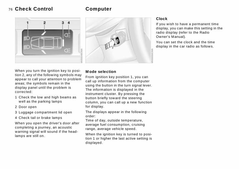
76nCheck Control Computer
k wish to have a permanent time y, you can make this setting in the display (refer to the Radio r's Manual).
an set the clock and the time y in the car radio as follows.
ClocIf youdisplaradio Owne
You cdispla
.
When you turn the ignition key to posi-tion 2, any of the following symbols may appear to call your attention to problem areas; the symbols remain in the
Mode selectionFrom ignition key position 1, you can call up information from the computer
display panel until the problem is corrected:
1 Check the low and high beams as well as the parking lamps
2 Door open
3 Luggage compartment lid open
4 Check tail or brake lamps
When you open the driver's door after completing a journey, an acoustic warning signal will sound if the head-lamps are still on.
using the button in the turn signal leverThe information is displayed in the instrument cluster. By pressing the button briefly toward the steering column, you can call up a new functionfor display.
The displays appear in the following order:Time of day, outside temperature, average fuel consumption, cruising range, average vehicle speed.
When the ignition key is turned to posi-tion 1 or higher the last active setting isdisplayed.

77n
Over
view
Cont
rols
Mai
nten
ance
Computer
warninge outside temperature drops to ut 37.5 7 (+3 6), then the puter will automatically switch to a lay of the outside temperature. In ition, a signal sounds as a warning the display flashes for a brief iod.
The ice warning does not alter the fact that surface ice can form at
peratures above 37.5 7 (+3 6), on ges or shaded road surfaces, for ance.<
et
IceIf thabocomdispaddandper
tembridinst
Repa
irs
Data
Inde
x
SettingsFrom ignition key position 1 and time displayed in the instrument cluster:
To set ahead: turn the button to the
Outside temperatureYou can change the units of measure(6/7) for the outside temperature display by pressing the right-hand res
right.
To set back: turn the button to the left.
The setting speed will increase the longer you continue to hold the button.
To change the display mode: press the button briefly.Every time you press the button, the clock display alternates between the 12-hour or 24-hour mode.
In ignition key position 0: the time is displayed for a few seconds after you press the left button, refer to Odometer on page 74.
button in the instrument cluster whilethe temperature display is active.

78nComputer
age speed continue to hold the button on the ignal lever, the average speed last yed is recalculated from that in time.
me spent when the vehicle is nary and the engine is switched ignored for the calculation.
AverIf youturn sdisplapoint
Any tistatiooff is
Average fuel consumptionIf you continue to hold the button on the turn signal lever, the average fuel
RangeThe computer bases its calculations forthe cruising range on the operating conditions in the preceding period andon the remaining fuel in the tank.
consumption last displayed is recalcu-lated from that point in time.

79n
Over
view
Cont
rols
Mai
nten
ance
Repa
irs
Data
Park Distance Control (PDC)*
The PDC does not remove the driver's personal responsibility for
luating the distance between the icle and any obstacles. Always ember that the sensors can neither ct nor provide warnings of obsta- located within their blind angles. applies especially in those cases re the system approaches the sical limits of ultrasonic measure-t, as occurs with tow bars and
er couplings, and in the vicinity of or wedge-shaped objects.tain sources of sound, such as a radio, could drown the PDC signal .<
Keep the sensors clean and free of ice or snow in order to ensure
they will continue to operate effec-ly.not apply high pressure spray to the sors for a prolonged period of time. ays maintain a distance of more 4 in (10 cm).<
us
er-
he
to
r
evavehremdeteclesThiswhephymentrailthinCerloudtone
thattiveDo senAlwthan
Inde
x
The conceptPDC provides extra safety and conve-nience during parking and all backing operations by providing an acoustic signal to indicate the distance between your rear bumper and the nearest object. The system features four ultra-sonic sensors mounted in your rear bumper. The monitoring range for the two corner sensors extends outward roughly 2 ft (60 cm), while two centrally located sensors detect objects at distances of up to approx. 5 ft (1.50 meters).
The system starts to operate automati-cally approx. one second after you
Acoustic signalsThe distance to the nearest object is indicated by a tone sounding at variointervals. As the distance between vehicle and object decreases, the intvals between the tones become shorter. A continuous tone indicates tpresence of an object less than 1 ft (30 cm) away.
The warning signal is canceled after approx. three seconds if the distancethe obstacle remains constant duringthis time (if you are moving parallel toa wall, for instance).
System malfunctions will be indicatedby a continuous high-pitched tone
select reverse or move the selector lever into the "R" position with the igni-tion key in position 2. PDC is deacti-vated when you shift back out of reverse.
when the system is activated the firsttime. Please refer the problem to youBMW center.

80nAutomatic Stability Control plus Traction (ASC+T)
h off the ASC+T the button; the indicator lamp s on and stays on.
lustration depicts the arrangement buttons if the vehicle is fully ped. This may vary, depending on uipment actually installed.
following rare situations, it may ective to deactivate the ASC+T rief period:
en rocking the vehicle or starting in deep snow or on loose surfacesen driving with snow chains.
To maintain vehicle stability, always drive with the ASC+T acti- whenever possible.<
SwitcPresscome
The ilof theequipthe eq
In thebe efffor a b
>Whoff
>Wh
vated
The conceptThis system optimizes vehicle stability and traction, especially when you are starting off, accelerating or when going through curves.ASC+T recognizes the danger present in traction loss and will increase driving stability and traction by reducing the engine's output, and if necessary, by applying the brakes to the rear wheels.
ASC+T is ready each time you start the engine.
Indicator lampThe indicator lamp in the instru-ment cluster goes out shortly after you switch on the ignition,
refer to pages 18, 19.
The indicator lamp flashes: ASC+T is actively controlling drive torque and braking intervention.
The indicator lamp fails to go out after the engine is started, or it comes on during normal driving and stays on:There is a system malfunction or the system was deactivated with the button. Consequently, interventions to increase driving stability (as described
in the preceding column) are no longeravailable. You can still drive the vehicleperfectly well without ASC+TIn the event of a fault, please contact your BMW center, refer to pages 18, 19.
81n
Over
view
Cont
rols
Mai
nten
ance
ASC+T Dynamic Stability Control (DSC)*
icator lampThe indicator lamp in the instru-ment cluster will go out shortly after the ignition has been
tched on, refer to pages 18, 19.
indicator lamp flashes: is actively controlling drive torque
braking intervention.
indicator lamp stays lit: has been deactivated manually; is operational. control intervention is not indi-d.
The indicator lamp and the brake warning lamps will remain on continuously:
it-
y g
is
y al
rt
Ind
swi
TheDSCand
TheDSCADBADBcate
Repa
irs
Data
Inde
x
The DSC, ADB and DBC have been deactivated with the button or are defective.
vehicle will remain completely rational, however, without DSC. In event of a fault, please consult your W center, refer to pages 18, 19.
Indicator and warning lamps for Canadian models.
c-
B) s - rit-
C
Theopethe BM
Switch the ASC+T back onPress the button again; the indicator lamp goes out.
The laws of physics cannot be repealed, even with ASC+T. An
appropriate driving style always remains the responsibility of the driver. We therefore urge you to avoid using the additional safety margin of the system as an excuse for taking risks.<
The conceptThe Dynamic Stability Control (DSC) maintains vehicle stability, even in crical driving situations.
The system optimizes vehicle stabilitduring acceleration and when startinfrom a full stop, as well as optimizingtraction. In addition, it recognizes unstable vehicle conditions, such as under- or oversteering, and, as far aspossible within the laws of physics, helps keeping the vehicle on a steadcourse by reducing the engine speedand brake applications to the individuwheels.
DSC is operational every time you sta
the engine. DSC incorporates the funtionality of the Automatic Differential Brake (ADB) and the Cornering BrakeControl (CBC).The Automatic Differential Brake (ADrelies on selective braking applicationat the drive wheels to furnish the functionality of a conventional limited-slipdifferential for enhanced traction in cical driving conditions such as those encountered on snow-covered road surfaces, etc.
The ADB is in standby mode when DSis deactivated.
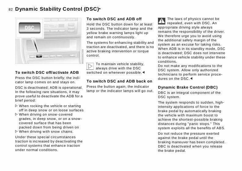
82nDynamic Stability Control (DSC)*
The laws of physics cannot be repealed, even with DSC. An priate driving style always ns the responsibility of the driver. erefore urge you to avoid using ditional safety margin of the as an excuse for taking risks.
ADB is in its standby mode, DSC ctivated; DSC does not intervene ance vehicle stability under these
tions.t make any modifications to the ystem. Allow only authorized
icians to perform service proce- on the DSC.<
mic Brake Control (DBC)is an integral component of the ystem.
ystem responds to sudden, high-ity applications of force to the pedal by automatically braking hicle with maximum boost to
ve the shortest-possible braking ces during "panic stops." This exploits all the benefits of ABS.
t reduce the pressure exerted
approremaiWe ththe adsystemWhenis deato enhcondiDo noDSC stechndures
DynaDBC DSC s
The sintensbrakethe veachiedistansystem
Do no
st the brake pedal until the g maneuver has been completed.is deactivated when you release ake pedal.
againbrakinDBC the br
To switch DSC off/activate ADBPress the DSC button briefly; the indi-cator lamp comes on and stays on.
To switch DSC and ADB offHold the DSC button down for at least 3 seconds. The indicator lamp and the yellow brake warning lamps light up and remain on continuously.
The systems for enhancing stability andtraction are deactivated, and there is noactive braking intervention or torque control.
To maintain vehicle stability, always drive with the DSC
switched on whenever possible.<
To switch DSC and ADB back on
DSC is deactivated; ADB is operational. In the following rare situations, it may prove useful to deactivate the ADB for a brief period:
>When rocking the vehicle or starting off in deep snow or on loose surfaces
>When driving on snow-covered grades, in deep snow, or on a snow-covered surface that has been packed down from being driven on
>When driving with snow chains.
Under these special circumstances traction is increased by deactivating the control systems that enhance traction under normal conditions.
Press the button again; the indicator lamp or the indicator lamps will go out.

83n
Over
view
Cont
rols
Mai
nten
ance
Repa
irs
Data
Tire Pressure Monitor (RDC)*
he event of loss in inflation ssuree inflation pressure has dropped ificantly over a long period of time ich is normal for any tire), the yellow cator lamp will come on.
alerts you to have the tires inflated he specified pressures as soon as sible.
If you are prompted to check the tire pressure shortly after a
ection has been made, this indi-s that the corrected values were accurate. Please check the inflation ssure again and make corrections ording to the inflation pressure e. Then activate the system once in.<
ot
e
C es to
e-
In tpreIf thsign(whindi
Thisto tpos
corrcatenot preacctablaga
Inde
x
i-r-
The conceptRDC monitors the tire pressures at all four wheels, even when the vehicle is moving. The system provides an alert whenever the inflation pressure drops significantly below the specified pres-sure in one or more tires.
In order for the system to learn the correct tire inflation pressure, check the inflation pressure in all tires according to the inflation pressure table on page 25 and make corrections as necessary. Then activate the system.
This indicator lamp in the instru-ment cluster will inform you if the tire pressure is not correct.
To activate the system1 Turn ignition key to position 2 (do n
start the engine)2 Press the button long enough for th
yellow indicator lamp in the instru-ment cluster to light up for a few seconds.
3 After a few minutes driving time, RDadopts the current inflation pressurin the tires as the reference valuesbe monitored.
You will only have to repeat this procdure following a correction of the tireinflation pressure. Otherwise, RDC functions automatically when the igntion key is in position 2, and thus opeates whenever the vehicle is driven.

84nTire Pressure Monitor (RDC)*
m interference devices using the same radio ncy can interfere with the RDC.
ellow indicator lamp will come on the malfunction.
dicator lamp also comes on
he event of a system fault wheel is mounted without the ropriate RDC electronics addition to the spare tire, addi-al wheels with RDC electronics being carried on board.
e contact your BMW center for onal information.
SysteLocalfreque
The yduring
The in
> in t> if a
app> if, in
tionare
Pleasadditi
In the event of a flat tireIf there is a tire failure with loss of pres-sure, the red warning lamp will come on. In addition, an acoustic signal is sounded.
If this occurs, reduce vehicle speed immediately and stop the vehicle in a safe location. Avoid hard brake applica-tions. Do not oversteer. Replace the wheel and flat tire.
The space-saver spare tire is provided for temporary use only in
the case of a flat tire. It does not have RDC electronics and is not monitored. The spare tire that has the same dimen-
The RDC cannot alert you to severe and sudden tire damage
caused by external factors.<
Have the tires changed by your BMW center.
Your BMW center has the information needed for working with RDC and is equipped with the necessary special tools.<
sions as the tires already mounted on the vehicle is equipped with the neces-sary RDC electronics and will be also monitored once the tires have been mounted and the system activated.<

85n
Over
view
Cont
rols
Mai
nten
ance
Flat Tire Monitor*
ress the button until the yellow indi-ator lamp in the instrument cluster ghts up. After a little while, the indi-ator lamp will go out by itselffter a few minutes driving time, the lat Tire Monitor adopts the current ressure levels as the reference and om that point on, can detect and
eport a flat tire.
he -
3. Pclic
4. AFpfrr
Repa
irs
Data
Inde
x
s or e m
n he ,
The conceptAs you drive, the Flat Tire Monitor keeps track of pressure levels in all four tires in order to detect and warn of any substantial pressure loss.
The system actually detects pressure loss by monitoring differences in the relative speeds of the four wheels. It interprets variations outside specified limits as severe pressure loss, and then responds by generating a warning.
Initializing the systemInitializing is necessary to familiarize tsystem with the correct inflation pressure.
Repeat this process after any changein tire inflation pressure, tire rotation replacement. Do not carry out furthersystem initialization after adjusting thinflation pressure and letting the syste"learn" the correct pressures.
1. Check the tire inflation pressures iall the tires, comparing them with tinflation pressure table on page 25and adjusting if necessary
2. Turn the ignition key to position 2

86nFlat Tire Monitor*
Check the tire inflation pressures on a regular basis, correcting as necessary, refer to page 24.ystem may respond to operation ppery or snow-covered road es with false warnings or delays ecting actual pressure loss.rmance-oriented driving (slip at ive wheels, high rates of lateral eration) can also increase the time e Flat Tire Monitor requires to
t a flat.<
m malfunctionsellow indicator lamp in the instru-cluster lights up and remains on
them The son slisurfacin detPerfothe draccelthat thdetec
SysteThe yment
he problem is corrected.
e refer the problem to your BMW r.
until t
Pleascente
To activate/deactivate the systemThe Flat Tire Monitor automatically assumes operation whenever you turn
In the event of a flat tireThe red warning lamp in the instrument cluster lights up to warn of pressure loss and tire
failure. This visual alert is accompaniedby an acoustic warning signal. Reduceyour speed immediately, and steer andbrake gently as you bring the vehicle toa stop.
To reset the warning lamp: after replacing the damaged tire you will need to reset the red warning lamp manually: maintain pressure on the FlatTire Monitor button until the warning lamp goes out. Then reinitialize the system.
the ignition key to position 2. Unlessmanually deactivated, it is always on during normal vehicle operation.
To deactivate the system: press the button, the yellow indicator lamp comes on.
To activate the system: press the button again, the indicator lamp goes out.
You should deactivate the system before driving with snow chains, as the chains can generate spurious warnings and/or prevent the system from detecting actual pressure loss.
The Flat Tire Monitor cannot provide you with advance warning
of sudden and severe tire damage caused by external factors.The system also does not detect the gradual and minor loss of pressure thatall tires display over extended periods of time.<

87n
Over
view
Cont
rols
Mai
nten
ance
Parking lamps/Low beams
omatic headlight control* When the switch is set to this position the system automati-cally activates and cancels the
beams in response to changes in ient light ( in tunnels, at dusk, etc.) ell as rain and snow.
The vehicle's external lights remain on constantly when you
tch on the front fog lamps after the dlights have come on automati-y.<
Automatic headlight control cannot serve as a substitute for
driver's judgement in determining
p he -ou
u off.
eft
Aut
lowambas w
swiheacall
the
Repa
irs
Data
Inde
x
n the vehicle lights should be tched on. For example, the sensors not able to detect fog. To avoid ty risks, you should respond to e kinds of low-visibility situations witching the headlights on manu-
.<
You can have the sensitivity of your vehicle's automatic head-
t control adjusted.<
wheswiare safethesby sally
ligh
Parking lampsThe front, rear and side vehicle lighting is switched on. You can use the parking lamps for
Follow me home lamps:When you activate the headlam
flasher after parking the vehicle with tlamps turned off, the low-beam headlamps will come on for a short time. Ycan also have this function deacti-vated.<
LIGHTS ON warningWhenever you open the driver's doorafter having turned the ignition key toposition 0, you will hear an acoustic signal for a few seconds to remind yoif the lamps have not been switched
Daytime driving lamps*
parking. For lighting on one side for parking as an additional feature, refer to page 88.Low beams When the ignition is switched off while the low beams are on, the headlamps go out and only the
parking lamps remain on.
If you desire, the light switch can be lin the second position: When the ignition is switched off, theexternal lighting is also switched off.
You can have your vehicle's daytime driving lamps set to
reflect your personal requirements.<

88nInstrument lighting High beams/Standing lamps Fog lamps
ampsThe green indicator lamp in the instrument cluster comes on to
Fog l
indicate that the front fog lamps .
If the automatic headlight control is on, the low beams will come on atically whenever you switch on nt fog lamps.<
are on
automthe fro
Turn the rotary dial to adjust the illumi-nation intensity.
1 High beams (blue indicator lamp)
2 Headlamp flasher (blue indicator lamp)
3 Standing lamps
Standing lamps, left or rightAs an additional feature, you can illuminate your vehicle on either side forparking:
With the ignition key in position 0, engage the lever in the appropriate turn-signal position.

89n
Over
view
Cont
rols
Mai
nten
ance
Interior lamps
.
Repa
irs
Data
Inde
x
a-
to s
r .<
The interior lamps operate automati-cally.
Switching the interior lamps on
Rear reading lampsRear reading lamps are also providedfor rear seat passengers when the hardtop is installed, refer to page 110
and off manuallyPress button 1 briefly:
If you want the interior lamps to remain off all the times, press and hold the button for approx. 3 seconds.
Press the button briefly to revert to normal operation.
Front reading lamps*Switch on and off with the button 2 adjacent to each lamp.
Switch on and off with the button adjcent to each lamp.
To avoid subjecting the battery excessive loads, all of the lamp
within the vehicle are automatically switched off approx. 15 minutes afteyou turn the ignition key to position 0

90nAir conditioning
and the side
area 92
4 Air supply 91
5 Temperature 91
6 Air distribution 91
r window defroster 91
conditioning 91
irculated-air mode 91
7 Rea
8 Air
9 Rec
1 Air onto the windshieldwindows
2 Air for the upper body
3 Air for the footwell

91n
Over
view
Cont
rols
Mai
nten
ance
Air conditioning
irculated-air modeYou can respond to unpleasant external odors by temporarily
pending the supply of outside air. system then recirculates the air ently within the vehicle.
If the windows should fog over in the recirculated-air mode, switch
f and increase the air supply as uired.<
ter p r
-
i-
Rec
susThecurr
it ofreq
Repa
irs
Data
Inde
x
r n
ra-le. d
Air supplyYou can select blower speeds from 1 to 4. The heating and ventilation become more and more effective as the air
supply settings are increased. In position 0, the blower and the heater are switched off. The outside air supply is blocked in position 0.
TemperatureIn order to increase the temperature of the passenger compartment, turn the temperature control to the
right (red). The temperature of the
Rear window defrosterWhen the rear window defrosis activated, the indicator lam
comes on. The rear window defrosteswitches off automatically.
The rear window defroster automatically assumes operation
within 5 minutes after the engine is started at outside temperatures belowapprox. 39 7 (+4 6).<
Air conditioningThe air is cooled and dehumidfied and – depending on the
temperature setting – rewarmed.
incoming air is kept constant.Air distributionYou can direct the emerging air toward the windows , toward your upper body or into the footwell . All inter-
mediate settings are possible. In the setting, there is a low flow of air onto
the windows to keep them free of condensation.
Depending on the weather, the wind-shield may fog over briefly when the engine is started. Switching on the aiconditioning will reduce condensatioforming on the windows.
Condensation forms in the air conditioning system during ope
tion, which then exits under the vehicTraces of condensed water of this kinare thus normal.<

92nAir conditioning
frost windows and remove ensation the blower speed control for the
To decond1. Set
low rate to position 4
n the rotary temperature control pletely to the right (red)
tary control for air distribution in ition
itch on the rear window defroster efrost the rear window.
airf
2. Turcom
3. Ropos
4. Swto d
Draft-free ventilationYou can adjust the blower controls for the upper body area to obtain the
MicrofilterThe built-in microfilter removes dust and pollen from the incoming air. Your BMW center will replace it during routine maintenance. A substantial reduction in airflow indicates that the filter needs to be replaced before scheduled maintenance.
optimum airflow rates and directions for your personal requirements:
1 Rotary dials for infinitely-variable opening and closing of the vent outlets
2 Selector levers for airflow direction
3 Rotary dial 3 allows you to control the temperature of the airflow from these outlets as desired.

93n
Over
view
Cont
rols
Mai
nten
ance
Repa
irs
Automatic climate control*
ld and the side
y area 95
e/Automatic ol (AUC) 95
5 Air supply 94
6 Temperature 94
7 Automatic air distribution 94
8 Individual air distribution 94
9 Interior temperature sensor – pleasekeep clear and unobstructed
Data
Inde
x
splay for temperature and air pply 94
defrost windows and remove ndensation 94
r conditioning 94
ar window defroster 95
10 Disu
11 Toco
12 Ai
13 Re
1 Air onto the windshiewindows
2 Air for the upper bod
3 Air for the footwell
4 Recirculated-air modrecirculated-air contr

94nAutomatic climate control*
frost windows and remove ensation
This program quickly removes ice and condensation from the
hield and the side windows.
onditioningThe air is cooled and dehumidi-fied and – depending on the
rature setting – rewarmed.nding on the weather, the wind- may fog over briefly when the e is started. Switching on the air tioning will reduce condensation g on the windows.
Condensation forms in the air conditioning system during opera-hich then exits under the vehicle.
s of condensed water of this kind us normal.<
To decond
winds
Air c
tempeDepeshieldengincondiformin
tion, wTraceare th
,
Tips for pleasant drivingUse the automatic system – switch on with AUTO button 7. Select the desired interior temperature.
Detailed setting options are described for you in the following section.
Automatic air distributionThe AUTO program adjusts the air distribution and the air
supply for you and – in addition to that – adapts the temperature to external influences (summer, winter) to meet preferences you can specify.
TemperatureThe interior temperature that appears in the display panel is a
general figure intended for reference purposes. We recommend 72 7 (+22 6) as a comfortable setting, evenif the air conditioning is on. When you start the vehicle, the system ensures that the selected temperature is achieved as quickly as possible. It thenmaintains this temperature, regardless of the season.
Air supplyBy pressing the left or right halfof the button, you can vary the
Individual air distributionYou can cancel the AUTO program by selecting specific distribution patterns to suit your own individual requirements.
While the AUTO program is then deacti-vated, the automatic airflow control remains in operation. The system directs air to the windows , the upper body and into the footwells . You can reactivate the automatic air distri-bution mode by selecting the AUTO button.
air supply. This deactivates the auto-matic control of the air supply, AUTO disappears from the display panel. Nevertheless, the automatic air distri-bution remains unchanged. You can reactivate the automatic air distributionmode by selecting the AUTO button.
When the lowest blower speed is set and you press the left half of the buttonall of the displays are canceled: the blower, heating and air conditioning areswitched off. The outside air supply is blocked. You can reactivate the systemby pressing any button for the auto-matic climate control.

95n
Over
view
Cont
rols
Mai
nten
ance
Repa
irs
Automatic climate control*
ft-free ventilation can adjust the blower controls for upper body area to select the imum airflow rates and directions for r personal requirements:
otary dials for infinitely-variable pening and closing of the vent utlets
elector levers for airflow direction
otary dial 3 allows you to control the
ter p r
-
DraYouthe optyou
1 Roo
2 S
3 R
Data
Inde
x
temperature of the airflow from these utlets as desired.
oAutomatic recirculated-air control (AUC)
You can respond to unpleasant external odors by temporarily
stopping the flow of outside air. The system then recirculates the air currently within the vehicle.
Press the button repeatedly to select one of three different operating modes.
> Indicator lamps off: outside airflow is on
> Left indicator lamp on – AUC mode: the system recognizes pollutants in the outside air and blocks the flow of air when necessary. The system then recirculates the air currently within the
Rear window defrosterWhen the rear window defrosis activated, the indicator lam
comes on. The rear window defrosteswitches off automatically.
The rear window defroster automatically assumes operation
within 5 minutes after the engine is started at outside temperatures belowapprox. 39 7 (+4 6).<
vehicle. Depending on the air quality, the automatic system then switches back and forth between outside air supply and recirculation of the air within the vehicle
> Right indicator lamp on: the flow of outside air into the vehicle is perma-nently blocked. The system then recirculates the air currently within the vehicle.
If the windows fog over in the recirculated-air mode, switch it off
and increase the air supply as required.<

96nAutomatic climate control* Glove compartment
ckwith one of the master keys. A r key will also be required to k the glove compartment.
If you turn over only your door and ignition key for valet parking, for ple, access to the glove compart-is not possible, refer to page 28.<
argeable flashlightashlight is located on the left-side of the glove compartment.ures integral overload-protection, an be left in its holder continu-
To loLock masteunloc
examment
RechThe flhand It featso it cously.
Be sure that the flashlight is switched off when it is inserted s holder. Failure to comply with recaution could lead to over-ing and damage.<
into itthis pcharg
Microfilter/activated-charcoal filterThe built-in microfilter removes dust and pollen from the incoming air. The activated-charcoal filter provides addi-tional protection by filtering gaseous pollutants from the outside air. Your BMW center replaces this combined filter as a standard part of your sched-uled maintenance. A substantial reduc-tion in airflow indicates that the filter needs to be replaced before scheduled maintenance. To open
Pull the handle. The lamp in the glove compartment comes on.
To closeFold the cover back up.
To prevent injury in the event of anaccident, close the glove
compartment immediately after use.<
97n
Over
view
Cont
rols
Mai
nten
ance
Repa
irs
BMW Universal Transmitter*
ecking for the conversion code etermine whether the original
d-held transmitter is provided with a version-code system, you may er read the instructions for the orig- hand-held transmitter or program a nnel key as described on the next e (left-hand column under gramming").
n press and hold the programmed nnel key of the BMW Universal smitter. If the indicator lamp of the
W Universal Transmitter flashes for seconds and then comes on dily, the original hand-held trans-er is provided with a conversion-e system. With a conversion-code tem, program the channel keys as cribed on the next page (right-hand mn under "Programming a hand- transmitter with conversion code").
-op
he e --
,
i- ral
e s
ChTo dhanconeithinalchapag"Pro
ThechaTranBMtwosteamittcodsysdescoluheld
Data
Inde
x
If you have additional questions, please consult your BMW center
all 1-800-355-3515. can also visit this website w.bmwusa.com.<
-
or cYouww
The concept The BMW Universal Transmitter replaces up to three hand-held trans-mitters of different devices such as garage-door openers, alarm systems, or door locking systems. The BMW Universal Transmitter recognizes and learns the transmitted signal of each of the original hand-held transmitters.
The signal of an original hand-held transmitter can be programmed on one of the three channel keys. Following that, each of the devices can be actuated with the appropriately-programmed channel key. The indicator lamp flashes to confirm transmission of
To Canadian residents: During programming, your hand
held transmitter may automatically sttransmitting after two seconds. This may not be long enough to program tBMW Universal Transmitter. If you arprogramming from one of these handheld transmitters, the Universal Transmitter's light may begin to flash in a series of double-blinks. If this occurscontinue to hold the key of the Universal Transmitter while you reactvate your hand-held transmitter. Youmay have to repeat this function sevetimes while programming.<
Before programming, read the
the signal.If the vehicle is sold, the memory of the channel keys should be cleared as described on page 99.
During programming and before every remote actuation of a
programmed device by the BMW Universal Transmitter, check to be sure that there are no persons, animals or objects within the actuation range of the device in order to prevent possible injuries or damage. Also, comply with the safety precautions of the original hand-held transmitter.<
"User information" section on page 99.<
Original hand-held transmitterIf this symbol is present on thpackaging or in the instructionof the original hand-held trans
mitter, it may be assumed that this hand-held transmitter is compatible with the BMW Universal Transmitter.

98nBMW Universal Transmitter*
ramming a hand-held mitter with conversion code Read and comply with the safety precautions on the previous <
programming the BMW Universal mitter, consult the instructions for ecific device. For using the BMW rsal Transmitter with a conver-ode system, note the following
emental programming instruc-
A second person facilitates programming of the BMW rsal Transmitter.<
gram the BMW Universal Trans-ter as described previously under ogramming"
Progtrans
page.
WhenTransthe spUnivesion-csuppltions:
Unive
1. Promit"Pr
ss and hold the programming key the receiver of the device for rox. two seconds until the gramming lamp on the device es on
ss the desired channel key of the W Universal Transmitter three es.
If you have additional questions, please consult your BMW center.<
-
2. Preon appprocom
3. PreBMtim
Programming 1 Channel keys
2 Indicator lamp
3. Hold the original hand-held trans-mitter up to the receiver integrated into the mirror, i.e., right near the keys, a maximum of 2 in (5 cm) away
Read and comply with the safety precautions on the previous
page.<
1. Turn the ignition key to position 2 2. For initial use: press and hold both
outside keys 1 until the indicator lamp 2 flashes, and then release them. The three channel keys are cleared
4. Press the transmission key of the original hand-held transmitter (arrow 2) and the desired channel key of the Integrated Universal Remote Control (arrow 1) simulta-neously. Release both keys as soon as the indicator lamp flashes rapidly
5. To program other original hand-heldtransmitters, repeat steps 3 and 4.
The corresponding channel key is nowprogrammed with the signal of the original hand-held transmitter.

99n
Over
view
Cont
rols
Mai
nten
ance
Repa
irs
BMW Universal Transmitter* Storage compartments
nt center armrest pen: press the button (arrow) and pward.
itional compartments and s* will find additional storage partments in the front doors and in center console. Storage nets are on front seat backrests.
-at
he e
in
t
FroTo olift u
AddnetYoucomthe the
Data
Inde
x
Clearing the channel keysRead and comply with the safety precautions on page 97.<
The memory of individual channel keys cannot be deleted. However, the three channel keys can be cleared together as follows:
> Press and hold both outside keys of the BMW Universal Transmitter until the indicator lamp flashes, and then release them.
All of the channel keys are cleared.
User informationDo not use this BMW Universal Transmitter with any garage door opener thlacks safety "stop" and "reverse" features as required by federal safetystandards (this includes any garage door opener model manufactured before April 1, 1982).
This device complies with part 15 of tFCC Rules. Operation is subject to thfollowing two conditions: as defined the regulations, this device may not cause harmful interference, and musaccept any interference received, including interference that may causeundesired operation.

100nStorage compartments Cellular phone* Ashtray, front*
pty on the edge of the open cover ): the ashtray moves up and can
To emPress(arrow
oved.
be rem
Beverage holder, coin boxA coin box and two beverage holders are provided in the center console.
Hands-free systemOn vehicles with telephone prepara-tion* or a communications package*,
the cover for the hands-free micro-phone is located on the headliner, nearthe interior lamp.For further information on using your cellular phone, refer to the separate Owner's Manual.

101n
Over
view
Cont
rols
Mai
nten
ance
Ashtray, front* Ashtray, rear*
in
d.
Repa
irs
Data
Inde
x
Cigarette lighterPress the lighter 1 in. You can remove the lighter from its socket for use as soon as it springs back out.
Hold or touch the hot cigarette lighter by the knob only. Holding
or touching it in other areas could result in burns.The cigarette lighter remains opera-tional when the ignition key has been removed. For this reason, children should never be left in the vehicle unat-tended.<
Cigarette lighter socket
To emptyPress on the edge of the raised coverthe opening direction (arrow): the ashtray moves up and can be remove
Suitable for attaching power supplies for flashlights, car vacuum cleaners, etc., up to a rating of approx. 200 watts at 12 volts. Avoid damage to the socket caused by inserting plugs of different shapes or sizes.

102nSki bag*
ss the release button in the gage compartment (arrow)e the magnetic holder to fasten cover panel to the back wall.
4. Prelug
5. Usthe
re the ski bag, perform the above in reverse sequence.
ring cargoSecure skis and any other objects stored in the bag by tightening the ing strap at the buckle.<
Make sure that the skis are clean before loading them into the bag. damage from sharp edges during g.<
,
To stosteps
Secu
retain
Avoidloadin
The ski bag allows the safe and clean transport of up to 4 pairs of standard skis or up to two snowboards.
The length of the ski bag and the addi-tional space provided in the luggage compartment make it possible to carry skis up to 6.8 ft (2.1 m) long. Because of the tapered shape of the bag, the ski bag can only accommodate two pairs of skis up to 6.8 ft (2.1 m) long.
Loading1. Take the safety belts out of their
holders
2. Press button downward (arrow) andremove the filler piece by pulling it forward
3. Extend the ski bag between the frontseats. The zipper provides conve-nient access to the inside of the bagand can also be left open to promotedrying

103n
Over
view
Cont
rols
Mai
nten
ance
Ski bag Cargo loading
With the convertible top closed, you can increase the space in the
age compartment, refer to page 35. recommend that you always fold convertible top compartment panel n as soon as you have removed
r cargo from the luggage compart-t. This way, you can be sure that
can always operate your convert- top at any time.he same time, when the top is ed you should fold the convertible compartment panel back up before
ing large objects in the luggage partment; this precaution will help
uce the likelihood of damage to er the convertible top compartment
luggWethe dowyoumenyouibleAt traistopstowcomredeith
Repa
irs
Data
Inde
x
our luggage.<
ndor y
When reattaching the cover, guide both bars into the guide and press
the cover back into place. Secure the safety belts in their holders again.<
Stowing cargo If you are transporting cargo in your BMW:
> Load heavy cargo as far forward as
possible – directly behind the luggage compartment partition – aas low as possible> Cover sharp edges and corners.

104nCargo loading
Securing cargo > For small, light items, use the rubber-lined, non-skid side of the floor mat
Always position and secure the cargo correctly. If you do not, it
can endanger the passengers during braking or evasive maneuvers.Do not exceed the approved gross vehicle weight or the approved axle loads, refer to page 146, otherwise thevehicle's operating safety is no longer assured and you are in violation of the law.Do not stow heavy or hard objects in the passenger compartment without securing them. Otherwise they could bethrown around during braking and evasive maneuvers and endanger the passengers.<
or secure using the luggage compart-ment net* or elastic straps
> For large, heavy pieces, consult your BMW center for load-securing devices*. Anchorages (arrow) are provided at the inner corners of the luggage compartment for attaching these devices.
Read and comply with the information enclosed with the load-securing devices.

105n
Over
view
Cont
rols
Mai
nten
ance
Repa
irs
Data
dex
Roof-mounted luggage rack for the hardtop*
,
In
A special roof-rack system is available as an optional extra for your BMW. Please observe the precautions included with the installation instruc-
You should therefore always remembernot to exceed the approved roof load capacity, the approved gross vehicle weight or the maximum axle loads when loading the rack. These weights are listed under Technical Data on page 146.
Make sure that the load is not too bulkyand attempt to distribute it evenly. Always load the heaviest pieces first (onthe bottom). Make sure that no objectswill be in the way when the luggage compartment lid is opening or closing.
Secure the roof luggage correctly and securely to prevent it from shifting or being lost during driving (danger to
tions.
AnchoragesAccess to the anchorages:To fold up the covers (arrow), please use the tool which is provided with the roof-rack system.
Loading and driving notesRoof-mounted luggage racks raise the center of gravity of the vehicle when they are loaded. For this reason, they exercise a major effect on the vehicle's handling and steering response.
following traffic).
Drive smoothly and avoid sudden acceleration or braking. Do not corner at high speeds.
The roof-mounted luggage rack and theroof load increase the aerodynamic resistance: increased fuel consumptionand additional stress on the vehicle's body are the result.

106n

107n
Over
view
Cont
rols
e
Overview
and features
maintenance
Controls
Operation,
Mai
nten
anc
Repa
irs
Data
Inde
x
Owner service procedures
Index
Technical data

108n
. You can prevent corrosion in the by periodically repeating this dure.
The brake lamps do not come on when you engage the parking . m for the brake system servo unit
ur BMW is available only when the e is running. When you move the le with the engine off – when g, for example – substantially r levels of pedal force will be ed to brake the vehicle.<
h
Break-in procedures
To ensure that your vehicle continues to provide maximum economy throughout an extended service life, we request that you devote careful attention to the following instructions.
Engine and differentialThe first 1,200 miles (2,000 km): Attempt to constantly vary both vehicle and engine speed during these initial miles while remembering to avoid engine speeds in excess of 4,500 rpm and/or vehicle speeds of over 100 mph (160 km/h):
Always obey all official speed limits.
TiresOwing to technical factors associated with their manufacture, tires do not achieve their full traction potential until an initial break-in period has elapsed. We thus ask you to drive with extra care during the first 200 miles (300 km).
Always obey all official speed limits.
When the vehicle is operated on wet or slushy roads, a wedge of
water may form between the tire and the road surface. This phenomenon is referred to as aquaplaning, or hydro-planing, and can lead to partial or complete loss of traction, vehicle
x. 300 miles (500 km) must e before the clutch starts to te at optimum efficiency. mber to engage the clutch care-uring this initial period.
Refrain from using full throttle and avoid pressing the accelerator beyond the kickdown point.
After the initial 1,200 miles (2,000 km) you can gradually increase both engine and vehicle speeds.
Please remember to observe the same break-in procedures if either the engine or the differential is replaced later in the course of the vehicle's service life.
control and braking effectiveness. Reduce your speed on wet roads.<
Brake systemApprox. 300 miles (500 km) must elapse before the brake pads and rotors achieve the optimal pad-surface and wear patterns required for trouble-free operation and an extended service life later on.
To break-in the separate parking brake drums, apply the parking brake lightly when coasting to a standstill (at a traffic signal, for instance); use caution to avoid posing a danger to other road
usersdrumsproce
brakeVacuuon yoenginvehictowinhigherequir
Clutc
ApproelapsoperaRemefully d
109n
Over
view
Cont
rols
Mai
nten
ance
Driving notes Antilock Brake System Brake system
ke fluid level e brake fluid level is too low and ke pedal travel has become longer, e may be a defect in one of the
ke system's hydraulic circuits.
Proceed to the nearest BMW center. It may be necessary to
ly higher levels of pressure to the al when stopping and braking ances may also be longer. Please ember to adapt your driving style ordingly.<
ps g, ty.
ull its
").
le
on.
d ts
BraIf thbratherbra
apppeddistremacc
Repa
irs
Data
Inde
x
its
Brakes: do not drive with your foot resting on the brake pedal. Even
light but consistent pedal pressure can lead to high temperatures, brake wear and possibly even brake failure.Aquaplaning: when driving on wet or slushy roads, reduce vehicle speed. If you do not, a wedge of water may form between the tires and the road surface. This phenomenon can lead to partial or complete loss of contact between the tires and road surface, vehicle control and braking ability.Driving through water: do not drive through water on the road if it is deeper than 1 ft (30 cm), and then only at walking speed. Otherwise, the vehicle's
The conceptThe Antilock Brake System (ABS) keethe wheels from locking during brakinthereby enhancing active driving safe
Braking with ABSIf you are in a situation that requires fbraking, you will exploit the full benefof the ABS system if you apply maximum pedal pressure ("panic stopSince the vehicle maintains steering responsiveness, you can avoid possibobstacles with a minimum of steeringeffort, despite the full brake applicati
Pulsation at the brake pedal combinewith sounds from the hydraulic circui
engine, the electrical systems and the transmission may be damaged.Clothes hooks (with hardtop): when hanging clothing from the hooks, be sure that they will not obstruct the driver's vision. Do not hang heavy objects on the hooks. If you do so, they could cause personal injury during braking or evasive maneuvers.<
indicates to the driver that ABS is in active mode.

110nBrake system Hardtop*
ot necessary to remove the fabric en in the winter, when the p is generally in constant use. u can also remove it at any time o problem. Before the fabric top
red in the convertible top artment, it must be absolutely dry er to avoid water spots and w from forming.ardtop offers reading lamps and s hooks that can be used just by
ing. In addition, a roof-rack can be ted, for more information, please ct your BMW center.
When suspending articles of
t
It is ntop evhardtoBut yowith nis stocompin ordmildeThe hclothepressmounconta
clothing from the hooks, be sure ey will not obstruct the driver's
. Do not hang heavy objects on oks. If you do so, they could personal injury during braking or e maneuvers.<
eople are required for installation oval. Work with extreme caution
er to avoid paint damage and ge to the body or hardtop.ilitate hardtop installation or al, you can obtain a specially
ned hardtop lift* or hardtop rack* r BMW center.
that thvisionthe hocauseevasiv
Two por remin orddamaTo facremovdesigat you
Disc brakesLimited vehicle use, extended periods with the vehicle parked or in storage, and operating conditions in which braking is restricted to gentle, low-pressure applications will all increase the tendency for corrosion to form on the rotors; this is often accompanied by a simultaneous accumulation of contamination on the brake pads. The pads must exert a certain minimal level of pressure against the rotors for the disc brakes' inherent self-cleaning effect to remain effective.
If the brake rotors are corroded, they will tend to respond to braking with a
with only a minimal amount of braking.By minimizing the loads placed on the brake system, this strategy helps ensure that optimal brake system response will remain available at all times. Use care to avoid exceeding theapproved engine-speed range, refer topage 74.
Do not coast with the clutch depressed or with the transmission
or selector lever in neutral. Do not coaswith the engine shut off. The engine provides no braking effect when the clutch is depressed and there is no power-assist for braking or steering
pulsating effect that even extended brake applications will fail to cure.
When driving in heavy rain and on wet roads it is useful to apply light pressure to the brake pedal every few miles. Monitor traffic conditions to ensure that this maneuver does not pose a hazard to you or to other road users. The heat generated in this process helps dry the pads and rotors to ensure that your brake system will respond with undi-minished efficiency when you need it.
When descending steep hills and extended grades, downshift to a gear that will allow you to continue safely
when the engine is not running.Never allow floor mats, carpets or any other objects to protrude into the area around the accelerator, clutch and brakepedals and obstruct their movement.<
Brake padsFor your own safety: use only brake pads that the manufacturer
has released for your particular vehiclemodel. The manufacturer cannot eval-uate non-approved brake pads to determine if they are suited for use, andtherefore cannot ensure the operating safety of the vehicle if they are installed.<

111n
Over
view
Cont
rols
Mai
nten
ance
Hardtop*
Release the front locking levers by pressing the buttons. The levers will release slightly. Raise the levers as far as the stop will allow
ly
od
4.
Repa
irs
Data
Inde
x
le
t-
he
StorageStoring the hardtop on the floor: Slide the styrofoam block that
came with the hardtop onto its center.
Installation1. Lower the side windows complete
and flip the sun blinds down. If necessary, remove the antenna r
The arrow on top of the styrofoam block has to be pointing upward when you are doing this.<
to avoid any damage2. On vehicles with manual convertib
top operation, first release the convertible top compartment lid, and, if necessary, open it some-what. On vehicles with fully-auto-matic convertible top operation, open the convertible top comparment lid slightly by pressing the button for the operation of the convertible top
3. Remove the trim pieces on both sides by pulling them off toward tback (arrow), and reclose the convertible top compartment lid

112nHardtop*
oval the same procedure as when
ling, just reverse the steps.
RemFollowinstal
5. Before installing, first flip the cover panels that are located underneath the left and right interior lamps down. To do this, press on the
9. To lock the hardtop in the front, keep pressing on the front locking levers until you hear them engage
10. Check the rubber weatherstrippingbetween the windshield frame and the top on both the left and right sides. If it is folded or bent out of place you should smooth it back into position by hand to ensure secure and reliable sealing.
Lift the hardtop carefully. Be extremely careful not to shift the
seals. Seals that have been shifted outof place or actually pulled out cause leaks.<
slight bump on the cover panel. There is a holder in the cover panel to securely store the trim pieces that have been removed (1)
6. Open the red release levers as far as the stop will allow (2)
7. Position the hardtop onto the supports with the help of a second person. Be sure to put the mount-ings exactly into the proper brackets
8. In the back, close the red locking levers by turning to the inside as far as the stop located behind the trim will allow. Flip the cover panels back into place
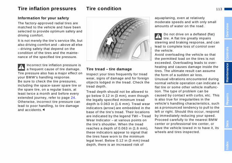
113n
Over
view
Cont
rols
Mai
nten
ance
aplaning, even at relatively erate speeds and with only small unts of water on the road.
Do not drive on a deflated (flat) tire. A flat tire greatly impairs
ring and braking response, and can to complete loss of control over vehicle. id overloading the vehicle so that permitted load on the tires is not eeded. Overloading leads to over-ting and causes damage inside the . The ultimate result can assume form of a sudden air loss.sual vibrations encountered during
mal vehicle operation can indicate a
Tire inflation pressures Tire condition
Information for your safetyThe factory-approved radial tires are matched to the vehicle and have been selected to provide optimum safety and driving comfort.
It is not merely the tire's service life, but also driving comfort and – above all else – driving safety that depend on the condition of the tires and the mainte-nance of the specified tire pressure.
Incorrect tire inflation pressure is a frequent cause of tire damage.
Tire pressure also has a major effect on your BMW's handling response.Be sure to check the tire pressures,
Tire tread – tire damageInspect your tires frequently for tread wear, signs of damage and for foreign objects lodged in the tread. Check the
Repa
irs
Data
Inde
x
tire or some other vehicle malfunc-. The type of problem can be sed by contact with curbs, etc. This lso true for irregularities in the icle's handling characteristics, such pronounced tendency to pull to the or right. Should this occur, respond mmediately reducing your speed. ceed carefully to the nearest BMW ter or professional tire center, or e the vehicle towed in to have it, its els and tires inspected.
including the space-saver spare tire or the spare tire, on a regular basis, at least twice a month and before every extended journey, refer to page 24. Otherwise, incorrect tire pressure can lead to poor handling, to tire damage and accidents.<
tread depth.
Tread depth should not be allowed to go below 0.12 in (3 mm), even though the legally specified minimum tread depth is 0.063 in (1.6 mm). Tread wearindicators (arrow) are embedded in thebase of the tire's tread. Their locations are indicated by the legend TWI – TreadWear Indicator – at various points on the tire's shoulder. When the tread reaches a depth of 0.063 in (1.6 mm), these indicators appear to signal that the tires have worn to the minimum legal level. Below 0.12 in (3 mm) tread depth, there is an increased risk of
aqumodamo
steeleadthe Avothe excheatiresthe Ununor
flat tioncauis avehas aleft by iProcenhavwhe

114nTire condition Tire replacement
ionaction grades, from highest to t, are AA, A, B, and C. grades represent the tire's ability p on wet pavement as measured controlled conditions on speci-overnment test surfaces of lt and concrete. A tire marked C ave poor traction performance.
The traction grade assigned to this tire is based on straight- braking traction tests, and does clude acceleration, cornering, planing, or peak traction charac-cs.<
-
TractThe trlowesThoseto stounderfied gasphamay h
aheadnot inhydroteristi
eraturemperature grades are A (the
st), B, and C, representing the resistance to the generation of nd its ability to dissipate heat
tested under controlled condi-on a specified indoor laboratory heel. ined high temperature can cause aterial of the tire to degenerate duce tire life, and excessive rature can lead to sudden tire . The grade C corresponds to a f performance which all nger vehicle tires must meet
-
TempThe tehighetire's heat awhentions test wSustathe mand retempefailurelevel opasse
Tire damage (up to and including sudden and complete air loss) can endanger the lives of both the vehicle occupants and other road users.<
To maintain good handling and vehicleresponse, use only tires of a single tread configuration from a single manufacturer.
DOT Quality GradesTread wear Traction AA A B C Temperature A B C
All passenger vehicle tires must conform to Federal Safety
Requirements in addition to these grades.<
Tread wear
The tread wear grade is a comparativerating based on the wear rate of the tirewhen tested under controlled condi-tions on a specified government test course. For example, a tire graded 150 would wear one and one-half (1 g) times as well on the government course as a tiregraded 100. The relative performance of tires depends upon the actual conditions of their use, however, and may depart significantly from the norm due to variations in driving habits, service practices and differences in road char-acteristics and climate.
115n
Over
view
Cont
rols
Mai
nten
ance
Tire replacement
ety tires*ety tires consist of self-supporting and special rims. The tire rein-ement ensures that the tire retains e residual safety in the event of
ssure drop and driving remains sible to a restricted degree. The icle is equipped with Tire Pressure itor (RDC) or Flat Tire Monitor,
ch indicate a flat tire. additional information on Tire Pres- Monitor (RDC) or Flat Tire Monitor r to page 83 or 85.
Safety tires are only possible in conjunction with Tire Pressure
itor (RDC) or Flat Tire Monitor.<
-he
as
l
e f
SafSaftiresforcsompreposvehMonwhiForsurerefe
Mon
Repa
irs
Data
Inde
x
under the Federal Motor Vehicle Safety Standard No. 109. Grades B and A represent higher levels of performance on the laboratory test wheel than the minimum required by law.
The temperature grade for each tire is defined for a tire that is
properly inflated and not overloaded. Excessive speed, underinflation, or excessive loading, either separately or in combination, can cause heat buildup and possible tire failure.<
Uniform Tire Quality Grading Quality grades can be found where applicable on the tire sidewall between
Tire ageThe date on which the tire was manufactured is indicated by the code on tsidewall:DOT ... 4101 indicates that the tire wmanufactured in week 41 of the year2001.
Although tires may have a theoreticaservice life of up to 10 years, BMW strongly recommends that you replacall tires after an absolute maximum o6 years.
tread shoulder and maximum section width. For example:
Tread wear 200 Traction AA Temperature A
Do not use retreaded tires, since driving safety may be impaired.
This is due to the possible variations in casing structures and, in some cases, to their extreme age, which can lead to a decrease in their durability.<

116nWheel and tire combinations
The right choiceNever mount wheels and tires that have not been specifically
approved by BMW for use on your particular model. Although other wheels and tires may theoretically have the same dimensions, variations in factors such as manufacturing tolerances can result in contact between tire and body-work, ultimately leading to serious acci-dents. BMW can not evaluate all tires and wheels on the market, and is thus unable to guarantee that the vehicle will continue to perform safely if unap-proved tires and/or wheels are mounted.<
The correct wheel and tire combi-nation affects various systems
that would otherwise be impaired, for example ABS, ATC, ASC+T/DSC and ADB/DBC.For this reason, use only tires of the same manufacture and tread configura-tion. In the event of a flat tire, for example, remount the approved wheel and tire combination as soon as possible.<

117n
Over
view
Cont
rols
Mai
nten
ance
Winter tires
ragere tires in a cool, dry place, tecting them against light whenever sible. Protect the tires against tact with oil, grease and fuel.
w chains*W narrow-link snow chains are nded for mounting on summer or ter tires in pairs at the rear wheels . Comply with all manufacturer's ty precautions when mounting the ins.
cannot mount snow chains with the wing tires:
/50 R 16 92
o
StoStoproposcon
SnoBMintewinonlysafecha
Youfollo
225
Repa
irs
Data
Inde
x
/45 R 17 91/40 ZR 17
n
225245
Choosing the right tireBMW recommends winter tires (M+S radial tires) for operation under inclement winter driving conditions. While all-season tires (M+S designa-tion) provide better winter traction than summer tires with the load ratings H, V, W, Y and ZR, they generally do not achieve the performance of winter tires.
In the interest of safe tracking and steering response, install winter tires made by the same manufacturer and with the same tread configuration on all four wheels.
Never exceed the maximum speed for which the winter tires
are rated.Unprofessional attempts by laymen tservice tires can lead to damage andaccidents.Have this work performed by trained professionals only. Any BMW center has the required technical knowledgeand the proper equipment and will behappy to assist you.<
Tire condition, tire pressureOnce the tire wears to below 0.16 in (4 mm), winter tires display a percep-tible decrease in their ability to cope with winter driving conditions, and
should be replaced in the interest of safety.Comply with the specified tire inflatiopressures — and be sure to have the wheel and tire assemblies balanced every time you change the tires.
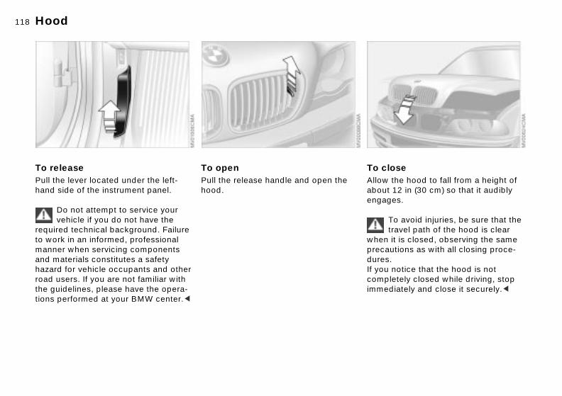
118n
ose the hood to fall from a height of 12 in (30 cm) so that it audibly
Hood
To releasePull the lever located under the left-hand side of the instrument panel.
To openPull the release handle and open the hood.
es.
To avoid injuries, be sure that the travel path of the hood is clear it is closed, observing the same utions as with all closing proce-. notice that the hood is not letely closed while driving, stop diately and close it securely.<
Do not attempt to service your vehicle if you do not have the
required technical background. Failure to work in an informed, professional manner when servicing components and materials constitutes a safety hazard for vehicle occupants and other road users. If you are not familiar with the guidelines, please have the opera-tions performed at your BMW center.<
To clAllowabout
engagwhenprecaduresIf youcompimme

119n
Over
view
Cont
rols
Mai
nten
ance
Repa
irs
Data
Engine compartment essentials
24
1
3 Coolant expansion tank 123
4 Reservoir for the headlamp and windshield washer system 120
ine oil filler neck 121
iliary terminal for p-starting 140
5 Eng
6 Auxjum
Inde
x
1 Brake fluid reservoir 1
2 Engine oil dipstick 12

120nWasher fluids
Headlamp* and windshield washer systemApproximate capacity is 5.6 US quarts
Antifreeze agents or intensive-cleaning washer fluids for the
washer systems are highly flammable. For this reason, keep them away from sources of flame and store only in orig-inal containers. Store them inaccessibleto children. Comply with the instruc-tions on the containers.<
(5.3 liters).
Fill with water and – if required – with a washer antifreeze (according to manu-facturer's recommendations).
We recommend that you mix the washer fluid before adding it to
the reservoir.<

121n
Over
view
Cont
rols
Mai
nten
ance
Engine oil
ing engine oilile you should wait until the level has pped to just above the lower mark re adding oil, you should never
s x. nd ss
AddWhdrobefo
Repa
irs
Data
Inde
x
w the oil level to fall below this k.
BMW engines are designed to operate without oil additives; the
of additives could lead to damage ome cases. This is also true for the ual transmission, the automatic smission, the differential, and the er steering system.<
ommendation: have the oil changed our BMW center.
allomar
usein smantranpow
Recat y
Checking oil level1. Park the vehicle on a level surface2. Switch the engine off after it has
reached normal operating tempera-
The oil volume between the two markon the dipstick corresponds to appro1.1 US quarts (1 liter). Do not fill beyothe upper mark on the dipstick. Exceoil will damage the engine.
ture3. After approx. 5 minutes, pull the
dipstick out and wipe it off with a clean lint-free cloth, paper towel, or similar material
4. Carefully push the dipstick all the way into the guide tube and pull it out again
5. The oil level should be between the two marks on the dipstick.
As with fuel economy, oil consumption is directly influenced by your driving style and vehicle operating conditions.

122nEngine oil
sity ratings sity is the oilflow rating as estab- in SAE classes.
election of the correct SAE class ds on the climatic conditions in ea where you drive your BMW.
Approved oils are in SAE classes 5W-40 and 5W-30.<
kinds of oil may be used for g in all ambient temperatures.
ViscoViscolished
The sdepenthe ar
Thesedrivin
Continuous exposure to used oil has caused cancer in laboratory
testing. For this reason, any skin areas that come into contact with oil should be thoroughly washed with soap and water.Always store oil, grease, etc., out of reach of children. Comply with all warning labels and information on lubri-cant containers.<
Comply with the applicable envi-ronmental laws regulating the
disposal of used oil.<
Specified engine oilsThe quality of the engine oil is extremely important for the operation and service life of an engine. Based onextensive testing, BMW has approved only certain grades of engine oil.
Use only approved "BMW High Performance Synthetic Oil."
If you are unable to obtain an approved"BMW High Performance Synthetic Oil," you may use small volumes of other synthetic oils for topping up between oil changes. Use only oils withthe specification API SH or higher.
Ask your BMW center for details concerning the specific "BMW
High Performance Synthetic Oil" or synthetic oils that have been approved.<
You can also call BMW of North America at 1-800-831-1117 or visit thiswebsite: www.bmwusa.com to obtain this information.

123n
Over
view
Cont
rols
Mai
nten
ance
Coolant
Comply with the applicable envi-ronmental laws regulating the
osal of extended-duty antifreeze corrosion inhibitor.<
e
nk
dispwith
Repa
irs
Data
Inde
x
e
he t
ler )
r
do
Do not add coolant to the cooling system when the engine is hot. If
you attempt to do so, escaping coolant can cause burns.To avoid the possibility of damage later on, never use anything other than factory-approved, nitrite and amino-free extended-duty antifreeze with corrosion inhibitor. Your BMW center is familiar with the official specifications. Antifreeze and anti-corrosion agents are hazardous to health. You should always store them in their original container and in a location which is out of reach of children.Extended-duty antifreeze with corro-sion inhibitor contains the flammable
Checking coolant levelCorrect coolant level when the enginis cold (approx. 68 7 or +20 6):
1. Open the cap for the expansion ta
substance ethylene glycol. For this reason, do not spill extended-duty anti-freeze with corrosion inhibitor on hot engine parts. It could ignite and cause serious burns.<by turning it slightly counterclock-wise to allow accumulated pressurto escape, then open
2. The coolant level is correct when tupper end of the red float is at leaseven with the upper edge of the filneck, but no more than 0.8 in (2 cmabove it – that is, up to the secondmark on the float (refer also to the schematic diagram next to the filleneck)
3. If necessary, add coolant.If the coolant is low, slowly add coolant until the correct level is reached – not overfill.

124nBrake fluid
,
Warning lampThe brake warning lamp comes on when the parking brake is
Brake fluid loss results in extended pedal travel. Refer to the information onpage 109.
Brake fluid is hygroscopic, that isit absorbs moisture from the air
over time.In order to ensure the brake system's safety and reliability, have the brake fluid changed every two years at a BMW center, refer to page 75 and to the Service and Warranty Information Booklet (US models) or the Warranty and Service Guide Booklet (Canadian models).Brake fluid is toxic and damages the
not engaged: the brake fluid level is too low, refer to page 17.
Brake warning lamp for Cana-dian models.
Adding brake fluidFor adding brake fluid or for deter-mining and correcting the cause of brake fluid loss, consult your BMW center. Your BMW center is familiar with the specifications for factory-approved brake fluids (DOT 4).
vehicle's paint. You should always storeit in original container and in a locationwhich is out of reach of children.Do not spill brake fluid and do not fill the brake fluid reservoir beyond the MAX mark. The brake fluid could igniteupon contact with hot engine parts andcause serious burns.<
Comply with the applicable envi-ronmental laws regulating
the disposal of brake fluid.<

125n
Over
view
Cont
rols
Mai
nte-
vice and Warranty Information klet (US models)/Warranty Service Guide Booklet nadian models) additional information on required ntenance intervals and procedures, se refer to the Service and
rranty Information Booklet (US els) or the Warranty and Service
de Booklet (Canadian models).
precaution against corrosion, if r vehicle is exposed to potential age from unimproved road aces we suggest that you have the y checked for damage from stone s and gravel at the same time.
The BMW Maintenance System
The BMW Maintenance System has been designed as a reliable means of providing maximum driving and oper-ating safety – and as cost-effectively as possible for you.
Service Interval DisplayWhile conventional systems rely on milage alone to determine when serviceis due, the BMW Maintenance System reflects the actual conditions under which the vehicle is operated: some miles are more strenuous than others.From a maintenance point of view, 62,000 miles (100,000 km) accumu-lated in short-distance urban driving arenot the equivalent of the same distancecovered at moderate cruising speeds inlong-distance highway travel.
The BMW Maintenance System moni-tors actual operating conditions as the basis for defining when the Engine Oil
Repa
irs
Data
Inde
x
We recommend that you refer all maintenance and repair opera-
s to your BMW center.sure that all maintenance work is firmed in the Service and Warranty rmation Booklet (US models), or in Warranty and Service Guide klet (Canadian models). These ies confirm that your vehicle has efitted from regular maintenance, are also required for warranty ms.<
Please keep in mind that regular main-tenance is not only necessary for the safety of your vehicle, but also plays a significant role in maintaining its resale value.
Service and Inspections I and II are due.
This service strategy accurately reflectsyour own vehicle's specific needs by defining maintenance intervals according to individual operating conditions. However, drivers who cover onlyextremely short distances – substan-tially less than 6,200 miles (10,000 km)annually – should still have the engine oil changed at least every 2 years, as itcontinues to age regardless of whetherthe vehicle is used on a regular basis.
-
SerBooand(CaFormaipleaWamodGui
As ayoudamsurfbodchip
tionBe conInfothe
Booentrbenandclai

126nTechnical modifications California Proposition 65 Warning
Light-emitting diodes (LEDs)Light-emitting diodes installed behind translucent lenses serve as the light source for many of the controls and displays in your vehicle. These LEDs are related to conventional lasers.
Do not remove the protective lens and avoid staring directly at the
unfiltered beam for extended periods (several hours), as inflammation of the iris could result.<
California laws require us to state the following warning:
Engine exhaust, some of its constituents, and certain vehicle
components contain or emit chemicals known to the State of California to cause cancer and birth defects or other reproductive harm.<
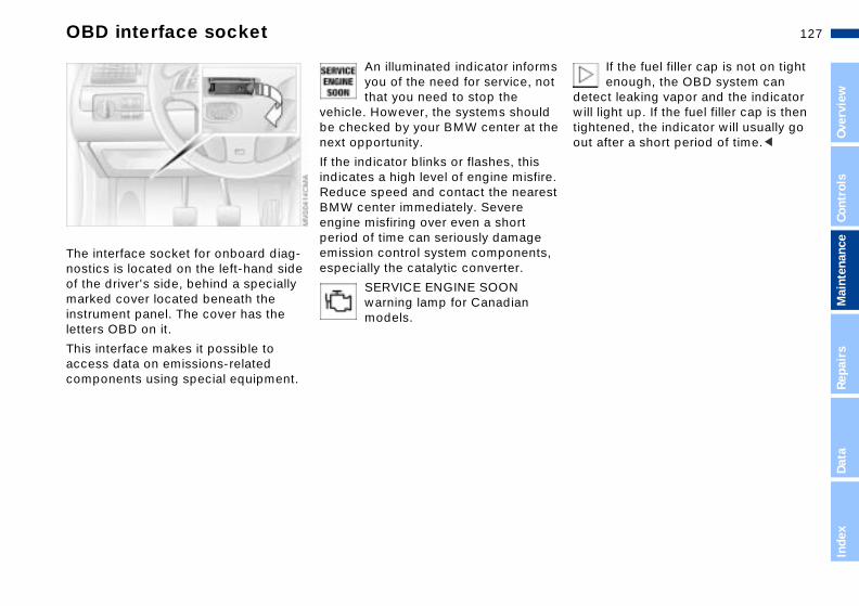
127n
Over
view
Cont
rols
Mai
nten
ance
OBD interface socket
If the fuel filler cap is not on tight enough, the OBD system can
ct leaking vapor and the indicator light up. If the fuel filler cap is then tened, the indicator will usually go after a short period of time.<
s ot
he
e. st
,
detewilltighout
Repa
irs
Data
Inde
x
The interface socket for onboard diag-nostics is located on the left-hand side of the driver's side, behind a specially marked cover located beneath the instrument panel. The cover has the
An illuminated indicator informyou of the need for service, nthat you need to stop the
vehicle. However, the systems shouldbe checked by your BMW center at tnext opportunity.
If the indicator blinks or flashes, this indicates a high level of engine misfirReduce speed and contact the neareBMW center immediately. Severe engine misfiring over even a short period of time can seriously damage emission control system componentsespecially the catalytic converter.
SERVICE ENGINE SOON warning lamp for Canadian
letters OBD on it.
This interface makes it possible to access data on emissions-related components using special equipment.
models.
128n
129n
Over
view
Cont
rols
e
Overview
and features
maintenance
Controls
Operation,
Mai
nten
anc
Repa
irs
Data
Inde
x
Owner service procedures
Index
Technical data
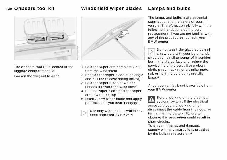
130n
mps and bulbs make essential butions to the safety of your le. Therefore, comply fully with the ing instructions during bulb ement. If you are not familiar with
f the procedures, consult your center.
Do not touch the glass portion of a new bulb with your bare hands even small amounts of impurities n to the surface and reduce the e life of the bulb. Use a clean paper napkin, or a similar mate-r hold the bulb by its metallic <
Onboard tool kit Windshield wiper blades Lamps and bulbs
The onboard tool kit is located in the luggage compartment lid.
Loosen the wingnut to open.
1. Fold the wiper arm completely out from the windshield
2. Position the wiper blade at an angle and pull the release spring (arrow)
acement bulb set is available from MW center.
Before working on the electrical system, switch off the electrical sory you are working on or nnect the cable from the negative al of the battery. Failure to ve this precaution could result in circuits.vent injuries and damage,
ly with any instructions provided bulb manufacturer.<
3. Fold the wiper blade down and unhook it toward the windshield
4. Pull the wiper blade past the wiper arm toward the top
5. Insert a new wiper blade and apply pressure until you hear it engage.
Use only wiper blades which have been approved by BMW.<
The lacontrivehicfollowreplacany oBMW
sinceburn iserviccloth,rial, obase.
A replyour B
accesdiscoterminobsershort To precompby the

131n
Over
view
Cont
rols
Mai
nten
ance
Lamps and bulbs
king lampsine compartment, left side:
urn the bulb holder to the left rrow) and remove it
e
ch ar ty
ve
ParEng
1. T(a
Repa
irs
Data
Inde
x
emove and replace the bulb.
att bulb
erhe by
2. R
5 w
Low and high beamsEngine compartment, left side:
1 Low beam
2 High beam
When cleaning the headlamps, please observe the following:
> Do not clean by wiping with a dry cloth (scratches). Never use abra-sives or strong solvents to clean thcovers
> Remove dirt and contamination (suas insects) by soaking with BMW CShampoo and then rinsing with plenof water
> Always use a deicer spray to remoaccumulated ice and snow – neveruse a scraper.<
Xenon lamps The service life of these bulbs is verylong and the probability of a failure is
H7 bulb, 55 watts
The H7 bulb is pressurized. There-fore, wear safety glasses and
protective gloves. Failure to comply with these precautions can result in physical injury if the bulb breaks.<
1. Press the two release catches at the front while simultaneously turning them to the left to remove the bulb holder
2. Remove and replace the bulb.
very low, provided that they are not switched on and off an unusual numbof times. If one of these bulbs shouldnevertheless fail, it is possible to continue driving with great caution using the fog lamps, provided local traffic laws do not prohibit this.
Because of the extremely high voltages involved, any work on t
lighting system should be carried out technically-qualified personnel only. Otherwise, there is a risk of fatal injury.<
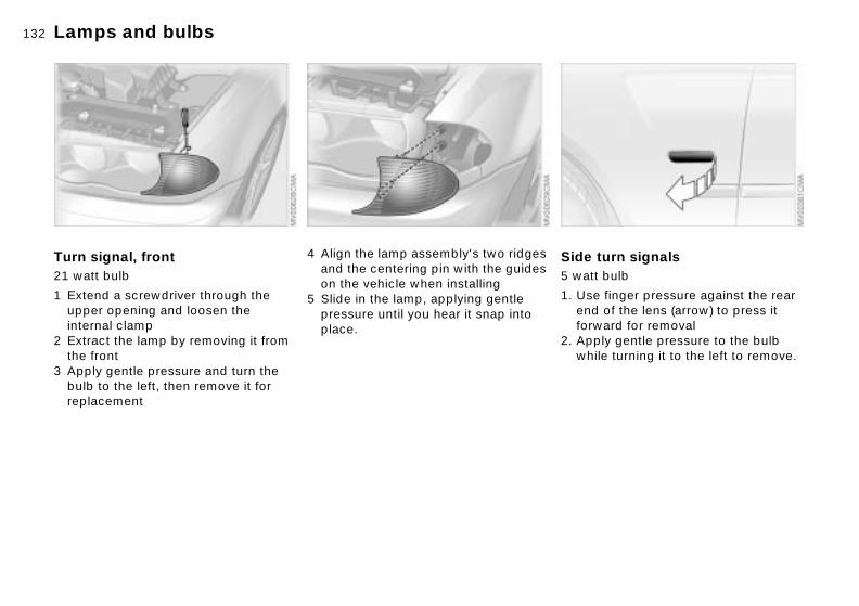
132nLamps and bulbs
turn signalst bulb
e finger pressure against the rear
Side 5 wat
1. Us
of the lens (arrow) to press it ard for removalply gentle pressure to the bulb ile turning it to the left to remove.
endforw
2. Apwh
Turn signal, front21 watt bulb
1 Extend a screwdriver through the
4 Align the lamp assembly's two ridgesand the centering pin with the guideson the vehicle when installing
5 Slide in the lamp, applying gentle
upper opening and loosen the internal clamp2 Extract the lamp by removing it from the front
3 Apply gentle pressure and turn the bulb to the left, then remove it for replacement
pressure until you hear it snap into place.
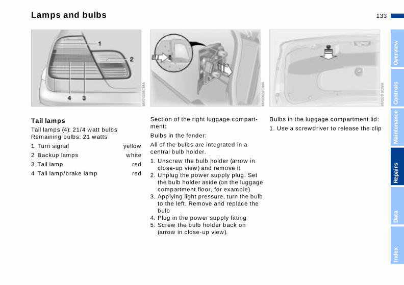
133n
Over
view
Cont
rols
Mai
nten
ance
Lamps and bulbs
bs in the luggage compartment lid:
se a screwdriver to release the clip
- Bul
1. U
Repa
irs
Data
Inde
x
t ge
lb e
Tail lampsTail lamps (4): 21/4 watt bulbs Remaining bulbs: 21 watts
1 Turn signal yellow
Section of the right luggage compartment:
Bulbs in the fender:
All of the bulbs are integrated in a
2 Backup lamps white
3 Tail lamp red
4 Tail lamp/brake lamp red
central bulb holder.
1. Unscrew the bulb holder (arrow in close-up view) and remove it
2. Unplug the power supply plug. Sethe bulb holder aside (on the luggacompartment floor, for example)
3. Applying light pressure, turn the buto the left. Remove and replace thbulb
4. Plug in the power supply fitting5. Screw the bulb holder back on
(arrow in close-up view).

134nLamps and bulbs
se plate lampst bulb
ce a screwdriver in the slot and
Licen5 wat
1. Pla
ss toward the left (arrow) to ase the lensplace the bulb.
prerele
2. Re
2. Fold the trim panel down (1). Release the bulb holder (2) and remove it
3. Applying light pressure, turn the bulb to the left. Remove and exchange the
Center (high-mount) brake lampLED strip on the rear window.
Please contact your BMW center in
bulb4. Press the bulb holder into place continuing until you hear it engage
5. Reinstall the trim panel with the clip.
case of a malfunction.

135n
Over
view
Cont
rols
Mai
nten
ance
Changing a wheel
at you will needrder to avoid rattling noises later, the position of the tools when you ove them and return them to their
r
he
ry ity
re
t,
WhIn onoterem
Repa
irs
Data
Inde
x
inal position when you are through g them.
ack 1aise the floor panel in the luggage ompartment, refer to page 35 and ndo the jack (arrow).hen you have completed work, fold e handle back and insert it in its
olderhock 2ocated behind the jack on the wall the luggage compartment. Loosen e wingnut to remove it
origusin
> JRcuWthh
> CLinth
Safety precautions for replacing flat tires and all wheel changes:
Stop the vehicle as far as possible from passing traffic. Park on a firm, flat, surface. Switch on the hazard warning flashers. Turn the steering wheel to the straight-ahead position and engage the steering lock. Shift into 1st or reverse (selector lever in Park with automatic transmission) and engage the parking brake.All passengers should be outside the vehicle and well away from your imme-diate working area (behind a guardrail, for example).If a warning triangle or portable hazard warning lamp is available, set it up on
Do not place wooden blocks or similaobjects under the jack. They could prevent the jack from extending to itsfull height and reduce its support capacity.Do not lie under the vehicle or start tengine when the vehicle is supportedby the jack – risk of fatal injury.<
Your BMW is equipped with a space-saver spare tire designed for temporause in maintaining the vehicle's mobilin an emergency.
To remove the space-saver spatire, lift the floor panel in the
luggage compartment completely ou
the roadside at an appropriate distance from the rear of the vehicle. Comply with all safety guidelines and regula-tions.Change the wheel only on a level, firm surface which is not slippery. Avoid jacking the vehicle on a soft or slippery support surface (snow, ice, loose gravel, etc.), as either the vehicle or the jack could slip sideways.Position the jack on a firm support surface.refer to page 35.<

136nChanging a wheel
sen the lug bolts by rotating half rnition the jack at the jacking point ows) closest to the flat tire with
-4. Loo
a tu5. Pos
(arr
jack base vertically below the king point and the entire surface he head of the jack will move into square recess of the jacking nt (refer to the detail in the next stration) when the jack is crankedntinue raising the vehicle up until wheel you are changing is raisedthe groundscrew the lug bolts and remove wheel
thejacof tthepoiillu
6. Cothefrom
7. Unthe
> Space-saver spare tireLocated next to the jack.Loosen the wing nut (arrow) by hand, remove the storage shelf and take the
Procedure1. Read and comply with the safety
precautions provided on the previouspage
2. Secure the vehicle to prevent it fromrolling:Place the chock against the rear surface of the front tire on the side opposite the side being raised. If thevehicle is parked on a downward slope, place the chock securely in front of the tire. If the wheel must bechanged on a surface with a more severe slope, take additional precautions to secure the vehicle from rolling
wheel out> Lug wrench – in the onboard tool kit
on the underside of the luggage compartment lid, refer to page 130.
3. Wheels with full wheel covers*: Reach into the ventilation openings and pull the cover off

137n
Over
view
Cont
rols
Mai
nten
ance
Changing a wheel
Only use original BMW full wheel covers, otherwise, the trim piece
not fit securely. The full wheel er may not be installed on the ce-saver spare tire, since this could age the cover.<
The vehicle jack is designed for changing wheels only. Do not
mpt to raise another vehicle model it or to raise any load of any kind. o so could cause accidents and
sonal injury.nsure continued safety, have the
tness of the lug bolts checked with librated lug wrench [torque specifi-on: 72 lb ft (72 100 Nm] at the
e
maycovspadam
attewithTo dperTo etigha cacati
Repa
irs
Data
Inde
x
iest opportunity.<
en storing a wheel in the spare tire ss take care to avoid bending the aded rod.
ht-alloy wheels other than original W light-alloy wheels have been nted, it may be necessary to use rent lug bolts for those wheels.
lace the defective tire as soon as sible and have the new wheel/tire nced.
n ity.or
to
irt y
earl
Whrecethre
If ligBMmoudiffe
Repposbala
8. Remove accumulations of mud and dirt from the mounting surfaces of the wheel and hub. Clean the lug bolts
9. Position the new wheel or the
13. Wheels with full wheel covers*: Place the wheel cover with the valve opening (arrow) over the valve. Use both hands to press thcover securely onto the rim
space saver spare tire on the hub and screw at least two lug bolts finger-tight into opposite bolt holes
10. Screw in the remaining lug bolts and screw in all the bolts in a diag-onal pattern
11. Lower the jack and remove it from beneath the vehicle
12. Tighten the lug bolts securely in a diagonal pattern
14. Check and correct the tire inflatiopressure at the earliest opportunVehicles with Tire Pressure Monit(RDC)/Flat Tire Monitor:After mounting the spare tire or correcting the tire inflation pres-sure, reactivate the system, referpage 83 or 85.
Protect valve stems and valves from dusing screw-on valve stem caps. Dirtvalve stems frequently lead to slow pressure loss.

138nChanging a wheel
Safety tires are only possible in conjunction with Tire Pressure or (RDC) or Flat Tire Monitor.<
defective wheel cannot be seen ch immediately from the outside, the tire inflation pressure at all heels.
Have the tires changed by your BMW center. For safety reasons, t have a safety tire repaired. Your center has the information d for working with safety tires equipped with the necessary
al tools.<
Monit
If the as sucheckfour w
do noBMWneedeand isspeci
If appropriate, please consult your BMW center to reequip your le from summer to winter tires – or ersa.<
-
vehicvice v
Driving with the space-saver spare tireDrive cautiously. Do not exceed a speed of 50 mph (80 km/h).
You can anticipate changes in vehicle handling such as delayed braking response, longer braking distances and sacrifices in roadholding.
The changes in handling characteristics will be even more pronounced in conjunction with winter tires.
Only one space-saver spare tire may be mounted at one time.
Reinstall wheels and tires of the same
Safety tires*Safety tires consist of self-supporting tires and special rims. The tire rein-forcement ensures that the tire retains some residual safety in the event of pressure drop and driving remains possible to a restricted degree. The vehicle is equipped with Tire Pressure Monitor (RDC) or Flat Tire Monitor, which indicate a flat tire.
Flat tireIf there is a tire failure, the red warninglamp symbol lights up. A supplemen-tary gong is also heard.For additional information on Tire Pres-
size and specification as soon aspossible. Maintain correct tire pres-sures, refer to page 25.<
sure Monitor (RDC) or Flat Tire Monitorrefer to page 83 or 85.
Reduce vehicle speed carefully to under 50 mph (80 km/h), avoiding hardbrake applications and steering maneuvers.
With the safety tires, you can drive another approx. 155 miles (250 km) to reach a safe parking location, a servicestation or the nearest BMW center. With a low vehicle load, this can also beconsiderably more than 155 miles (250 km).

139n
Over
view
Cont
rols
Mai
nten
ance
Battery Fuses
fuses are located in the glove partment behind a cover secured wo snap clips.
Do not attempt to repair a blown
s. i-
ng in
t.< Thecomby t
Repa
irs
Data
Inde
x
fuse or replace it with a fuse ing a different color or amperage g. To do this could cause a fire in vehicle resulting from a circuit over-.<
havratinthe load
Battery careThe battery is maintenance-free, that is, the original electrolyte will normally last for the service life of the battery under moderate climatic conditions.
Please consult your BMW center whenever you have any questions
concerning the battery. The battery is completely maintenance-free; the following section is provided for your information only.<
Never disconnect the battery when the engine is running; the
ensuing voltage surge would seriously damage the vehicle's onboard elec-
Charging the batteryWhen charging the battery in the vehicle, leave the engine off at all timeConnect the charge cables to the termnals in the engine compartment. For terminal locations refer to Jump-starting on page 140.
Return used batteries to a recyclipoint or your BMW center. Mainta
the battery in an upright position for transport and storage. Secure the battery against tilting during transpor
tronic systems.<

140n
Always adhere to this sequence when connecting jumper cables; to observe this procedure can o sparks at the battery terminals ose an injury hazard.<
rt the support vehicle's engine let it run at an increased idling ed for a few minutes. Start the ine on the vehicle needing the p-start, and allow it to run as al. If the first start attempt is not cessful, wait a few minutes ore another attempt in order to w the discharged battery to harge
Jump-starting
Do not use spray starter fluids to start the engine.
When your battery is discharged you can used two jumper cables to start your vehicle with power from the battery in a second vehicle. You can also use the same method to help start another vehicle. Always use jumper cables with fully insulated handles on the terminal clamps.
Do not touch high-voltage wiring and cables on a running engine.
Contact with components carrying high voltage can be harmful or fatal. Care-fully observe the following instructions
4. Start the engine on the support vehicle and allow it to run
5. Use one jumper cable (+) to connect the positive terminal of the battery in
fore disconnecting the jumper les let the engines run for a few utesn disconnect the jumper cables everse sequence.
nding on the cause of the fault, the battery recharged by your center.
to avoid personal injury and/or damage to one or both vehicles.<
1. Ensure that the battery in the support vehicle is also rated at 12 volts. This information is provided on the top of the battery casing
2. Do not disconnect your battery from your vehicle's electrical system. Switch off all electrical accessories in both vehicles
3. Make absolutely certain that there is no contact between the bodywork of the two vehicles – short circuit hazard
the support vehicle with the auxiliary positive terminal provided in the engine compartment of your BMW (arrow 1). The cover on this auxiliary terminal is identified by a "+" symbol. Remove by pulling the tab
6. Next, connect one end of the other jumper cable (–) to either the support vehicle's negative battery terminal or a suitable ground on its engine or bodywork. Connect the other end to the negative battery terminal or a suitable ground on the vehicle being started. There is a special nut on your BMW (2)
failurelead tand p
7. Staandspeengjumususucbefallorec
8. Becabmin
9. Thein r
Depehave BMW

141n
Over
view
Cont
rols
Mai
nten
ance
Towing the vehicle
ing with a commercial tow k
o not tow with sling-type equipmentse wheel-lift or flatbed equipment
w-p.
Towtruc> D> U
Repa
irs
Data
Inde
x
lease comply with applicable state wing laws.
Never allow passengers to ride in a towed vehicle for any reason.
er attach tie-down hooks, chains, ps, or tow hooks to tie rods, control s, or any other part of the vehicle pension, as severe damage to these ponents will occur, leading to
sible accidents.c
l ., rol se
> Pto
Nevstraarmsuscompos
Tow fittingThe screw-in tow fitting is stored in the onboard tool kit; be sure that it remains in the vehicle at all times. This fitting is
Rear:Press out the cover panel with a scredriver inserted in the recess at the to
Screw the tow fitting all the way
designed for installation in the tow sockets located at the front and rear of the vehicle, and is intended for towing on paved road surfaces only. This fitting should not be used to pull a vehicle out of deep snow, mud, sand, etc.Always comply with all applicable towing laws and regulations.Access to tow socketsFront:Press out the cover panel with a screw-driver inserted in the recess at the top.
in. Failure to screw the fitting althe way in can cause thread damageNever attach tie-down hooks, chainsstraps, or tow hooks to tie rods, contarms, or any other part of the vehiclesuspension, as severe damage to thecomponents will occur, leading to possible accidents.<
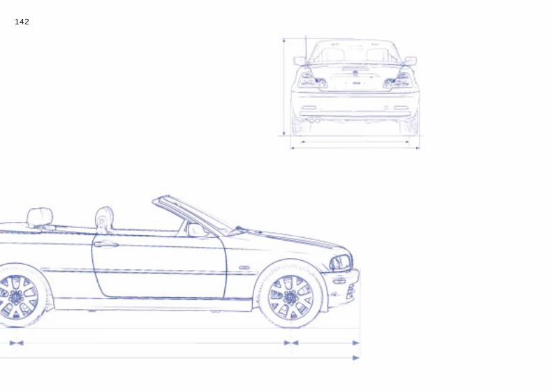
142n

143n
Over
view
Cont
rols
aint
enan
ce
Overview
Controls and features
Operation, maintenance
MRe
pair
sDa
tade
x
Owner service procedures
Index
Technical data
In
Index

144n
0Ci
,979)
)
)
.6))
gement system (DME)
Engine data
BMW 325Ci BM
DisplacementNumber of cylinders
cu in (cmm) 152.2 (2,494)6
186
Maximum powerat engine speed
hp (kW)rpm
184 (135)6,000
225,
Maximum torqueat engine speed
lb ft (Nm)rpm
175 (237)3,500
213,
Compression ratio e 10.5 10
StrokeBore
in (mm)in (mm)
2.95 (75)3.31 (84)
3.3.
Fuel-injection system Digital electronic engine
W 33
1.8 (2
5 (165900
4 (290500
.2
53 (8931 (84
-mana

145n
Over
view
Cont
rols
Mai
nten
ance
Repa
irs
Data
Inde
x
Dimensions
Minimum turning circle dia. 34.4 feet (10.5
m).
146nWeights
BMW 330Ci
3,616 (1,640)3,704 (1,675)
4,497 (2,040)4,575 (2,075)
2,094 (950)
2,579 (1,170)
165 (75)
9.2 (260)10.6 (300)
cluded)
ht.
BMW 325Ci
Curb weight (with one person, ready for operation, full tank of fuel, options not inwith manual transmissionwith automatic transmission
lbs. (kg) lbs (kg)
3,560 (1,615) 3,627 (1,645)
Approved gross vehicle weightwith manual transmissionwith automatic transmission
lbs (kg) lbs (kg)
4,442 (2,015) 4,509 (2,045)
Approved front axle loads lbs (kg) 2,083 (945)
Approved rear axle loads lbs (kg) 2,546 (1,155)
Approved maximum roof weight for the hardtop lbs (kg) 165 (75)
Luggage compartment capacity with the convertible top compartment raised
cu ft (l)cu ft (l)
9.2 (260)10.6 (300)
Never exceed either the approved axle loads or the approved gross vehicle weig
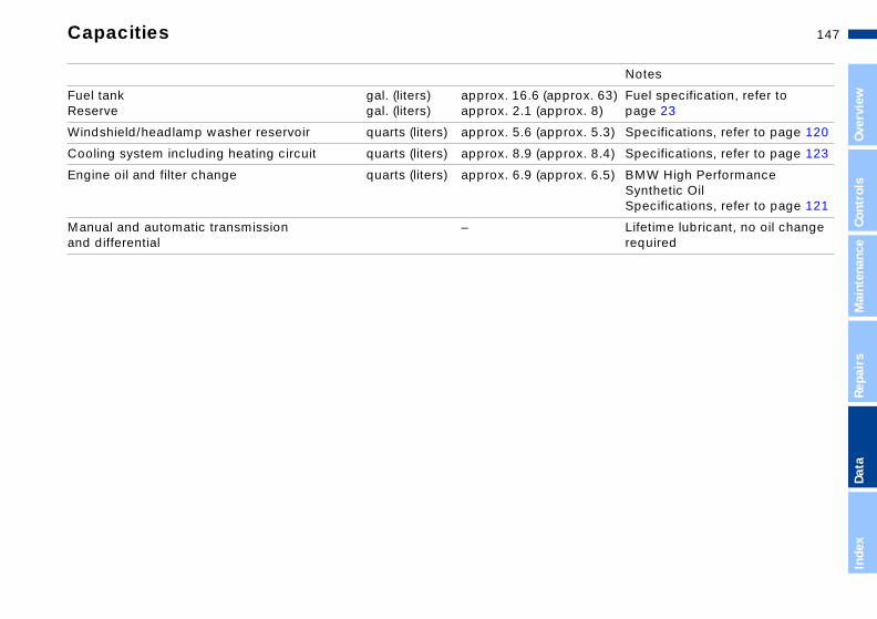
147n
Over
view
Cont
rols
Mai
nten
ance
Repa
irs
Data
Inde
x
Capacities
Notes
) Fuel specification, refer to page 23
) Specifications, refer to page 120
) Specifications, refer to page 123
) BMW High Performance Synthetic Oil Specifications, refer to page 121
Lifetime lubricant, no oil change required
pprox. 63prox. 8)
prox. 5.3
prox. 8.4
prox. 6.5
Fuel tank Reserve
gal. (liters)gal. (liters)
approx. 16.6 (aapprox. 2.1 (ap
Windshield/headlamp washer reservoir quarts (liters) approx. 5.6 (ap
Cooling system including heating circuit quarts (liters) approx. 8.9 (ap
Engine oil and filter change quarts (liters) approx. 6.9 (ap
Manual and automatic transmission and differential
–

148n

149n
Over
view
Cont
rols
aint
enan
ce
Overview
Controls and features
Operation, maintenance
MRe
pair
sDa
tade
x
Owner service procedures
Index
Technical data
In
Index
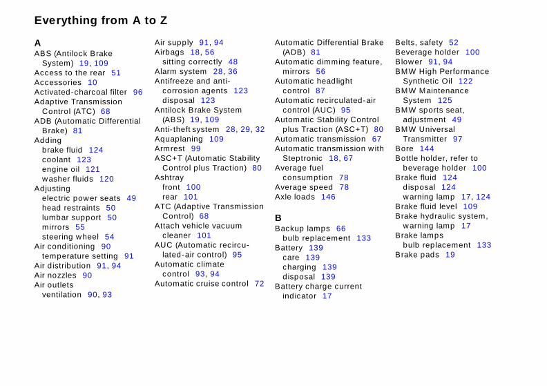
Everything from A to Z
A ABS (Antil
System)Access toAccessoriActivated-Adaptive T
Control ADB (Auto
Brake)Adding
brake flucoolantengine owasher
Adjusting electric head reslumbar smirrorssteering
Air condititempera
Air distribAir nozzleAir outlets
ventilati
l B
eat
d-
ontrol +T) 80 ion 67 ion with
Belts, safety 52 Beverage holder 100 Blower 91, 94 BMW High Performance
Synthetic Oil 122 BMW Maintenance
System 125 BMW sports seat,
adjustment 49 BMW Universal
Transmitter 97 Bore 144
ock Brake 19, 109
the rear 51 es 10 charcoal filter 96 ransmission
(ATC) 68 matic Differential 81
id 124
Air supply 91, 94 Airbags 18, 56
sitting correctly 48 Alarm system 28, 36 Antifreeze and anti-
corrosion agents 123 disposal 123
Antilock Brake System (ABS) 19, 109
Anti-theft system 28, 29, 32 Aquaplaning 109 Armrest 99
Automatic Differentia(ADB) 81
Automatic dimming fmirrors 56
Automatic headlight control 87
Automatic recirculatecontrol (AUC) 95
Automatic Stability Cplus Traction (ASC
Automatic transmissAutomatic transmiss
fl
p
ot
133
Bottle holder, refer to beverage holder 100
Brake fluid 124 disposal 124 warning lamp 17, 124
Brake fluid level 109 Brake hydraulic system,
warning lamp 17 Brake lamps
bulb replacement 133 Brake pads 19
123 il 121 uids 120
ower seats 49 traints 50 upport 50 55 wheel 54 ning 90 ure setting 91 tion 91, 94
ASC+T (Automatic Stability Control plus Traction) 80
Ashtray front 100 rear 101
ATC (Adaptive Transmission Control) 68
Attach vehicle vacuum cleaner 101
AUC (Automatic recircu-lated-air control) 95
Automatic climate
Steptronic 18, 67 Average fuel
consumption 78 Average speed 78 Axle loads 146
B Backup lamps 66
bulb replacementBattery 139
care 139 charging 139
nt
A-Z
us 90 on 90, 93
control 93, 94 Automatic cruise control 72
disposal 139 Battery charge curre
indicator 17
rake
ure,
air

Everything from A to Z 151n
Over
view
Cont
rols
ce
Brake sysbrake pabrake rocorrosiodefect incircuitsdisc bra
Break-in pBulbs and
replacem
C California
65 WarnCanned b
holderCapacitiesCar care, r
for your Car phoneCar wash
the "Carvehicle"
Care of uprefer tovehicle
er's
144
"Owner's ard
Coolant 123 capacity 147
Coolant temperature gauge 75
Cooling system, capacity 147
Copyright 4 Cornering Brake Control
(CBC) 18, 81 Correct sitting posture 48 Cruise control 72 Cruising range 78 Cup holder, refer to
tem 108, 109 ds 110 tors, n 110 hydraulic 109
kes 110 rocedure 108 lamps, ent 131
Cargo loading 103 CBC (Cornering Brake
Control) 18, 81 Cellular phone
refer also to the "Telephone Owner's Manual"
Center (high-mount) brake lamp 134
Center armrest 99 Central locking system 28
inside control button 32 Changing a wheel 135
Clock 76 refer also to the "Telephone OwnManual"
Clutch 108 Cockpit 14 Coin box 100 Compartments 99Compression ratioComputer 76
refer also to the Manual for OnboComputer"
Mai
nten
anRe
pair
s
Propositioning 126
everage 100
147 efer to the vehicle" m
100 systems, reing for you manual holstery m
ual cle and
ation via
onvertible
31
nel 35
beverage holder 100 Curb weight 146
D Data
dimensions 145 engine 144 weights 146
Daytime driving lamps 87 DBC (Dynamic Brake
Control) 82 Defrost windows 92, 94
"Caring anual
fer to r
aterials, for your
Charging the battery 139 Check Control 76 Check engine oil level 121 Checking coolant level 123 Checking tire pressures 24 Child-restraint systems 59 Cigarette lighter 101 Cleaning headlamps 71 Cleaning windshield 71
Configuring individsettings via VehiKey Memory 63
Consumption 78 display 75
Convenience operdriver's door lockfully-automatic ctop 31 power windows
Convertible top compartment pa
Data
Inde
x
lly tion 42
Digital clock 76 Dimensions 145 Dipstick, engine oil 121 Displacement 144
the "Caring" manual Convertible top, fu
automatic opera

Everything from A to Z
Display liDisplaysDisposal
antifreecorrosibatterybrake fengine
DistanceDoor keyDoors
electriclockingmanua
DOT Quatires 1
Draft-freeDrive belDriving nDSC (Dyn
ControDSC Dyn
ControDynamic
(DBC)Dynamic
(DSC)
Flat Tire Monitor 85, 115, 138
Flat tires 113, 135, 138 Floor panel, luggage
compartment 35 Fog lamps 88 Follow me home lamps 87 Front fog lamps 88 Front reading lamps 89 Fuel consumption 78 Fuel consumption
display 75
ghting 88 15
ze and anti-on agents 123
139 luid 124 oil 122 warning 79 s 28
al malfunction 31
E Easy access to the rear 51 Electric power seats,
adjustment 49 Electric power windows 38 Electrical malfunction
doors 31 fuel filler door 22 luggage compartment lid 33
Electrical malfunction, closing only
Engine data 144 Engine oil
consumption 121disposal 122 fluid capacity 147quality 122 specifications 122viscosity 122
Engine oil level 121check 121 indicator 19
Engine oil pressure
and ul operality Gr14 ventits 17 otes 1amic
l) 81 amic Sl 19, 8 B8
S1
65
6 7
Fuel filler door 22 electrical malfunction 22 manual operation 22
Fuel gauge 75 Fuel reserve indicator 75 Fuel specifications 23 Fuel tank capacity 147 Fuel tank gauge 75 Fuel-injection system 144 Fully-automatic convertible
top 42 electrical malfunction,
nlocking 29 tion 31 ades,
lation 92, 95
09 Stability
tability 1
Control
fully-automatic convertible top 44
Elements of operation 14 Emergency release of
luggage compartment lid from luggage compartment's interior 34
Energy Control 74 Engine and differential 108 Engine compartment
essentials 119 Engine coolant, refer to
indicator 17 Engine speed 144 Engine, starting 64 Engine, switching offEnlarging luggage
compartment 35 Entering the rear 51Exterior mirrors 55
F Failure messages 7Filling capacities 14
and closing only 44 manual closing 44
Fuses 139
rake2 tability Control 9, 81
coolant 123 Fittings, tow startingtowing 141
Flashlight 96

Everything from A to Z 153n
Over
view
Cont
rols
ce
1
Luggage compartment lid electrical malfunction 33 manual operation 33 operate via remote control 30
Luggage compartment lighting 33
Luggage compartment's interior, emergency release 34
Luggage rack 105 Lumbar support 50
G Garage-door opener 97 Gasoline gauge 75 Glove compartment 97 Gross vehicle weight 146
H Handbrake 66 Hands-free system 100
microphone 100 Hardtop 110 Hazard warning triangle 22
I Ice warning 77 Icy roads 77 Ignition keys 28 Ignition lock 64 Imprint 4 Indicator lamps 17 Inflation pressures,
tires 24, 113 INSPECTION 75 Instrument cluster 15 Instrument lighting 88
J Jack 135 Jump-starting 140
K Key Memory 63 Key set 28 Keys 28
L Lamps and bulbs,
replacement 13
Mai
nten
anRe
pair
s
Head resHeadlamHeadlamHeadlam
systemcapac
HeadlighHeated sHeavy caHeight 1High bea
bulb reHi
Ho
HoHo
int
s, bulb 4 g 87 ices 104
t 131
M M+S tires 117 Maintenance 125 Malfunction displays 76 Manual closing
fully-automatic convertible top 44
Manual convertible top 39 close 41 open 39
Manual operation doors 31
traints 50 p cover, care 131 p flasher 88 p washer
120 ity 147 t control 87 eats 54 rgo 103 45 ms 20, 69, 88 placement 131 formance Synthetic
Instrument panel 15 Interface socket for onboard
diagnostics (OBD) 127 Interior lamps 30, 89
remote control 30 Interior motion sensor 36
operating via remote control 30 switching off 37
Interior rearview mirror 55 with automatic dimming 56
Interlock 64
Lashing eyes 104LATCH child-restra
system 59 Length 145 License plate lamp
replacement 13LIGHTS ON warninLoad-securing devLock buttons 32 Low beams 87
bulb replacemenLug wrench 135
Data
Inde
x
ent 35
y 33
fuel filler door 22 luggage compartment lid 33
gh PerOil 122 lder for canned
beverages 100 od 118 rn 14
Luggage compartmcapacity 146 enlarging 35 floor panel 35 secure separatel

Everything from A to Z
13
ar
Rearview mirror 55 Recirculated-air mode 91 Refueling 22 Remote control 29 Remove window
condensation 92, 94 Replace windshield wiper
blades 130 Replacement keys 28 Replacing lamps and
bulbs 130 Reporting safety defects 11
Manual transmission 66 Manually controlled recircu-
lated-air 95 Master keys 28 MFL (Multifunction steering
wheel) 22 Microfilter 92, 96 Mirror defrosting 55 Mirror memory 53 Mirrors 55 Mobile phone, refer to
cellular phone 100
Oil change intervals, refer to the Service and Warranty Information Booklet (US models) or the Warranty and Service Guide Booklet (Canadian models)
Oil dipstick 121 Oil filter change 147 OIL SERVICE 75 Onboard computer 76
refer also to the "Owner's Manual for Onboard
Parking aid 79 Parking brake 66 Parking lamps
bulb replacementPDC (Park Distance
Control) 79 Phone, refer to cellul
phone 100 Pocket light 96 Power windows 38
M
M
MM
OOBOdOi
114
133
Reverse 66 Rollover protection
system 61 Roof weight 146 Roof-mounted luggage
rack 105
S Safe with safety belts 48 Safety belts 48, 52
seat-integrated 51 Safety defects, reporting 11
odifications, technical 10, 126 otion sensor, refer to interior motion sensor 36 ounting the roof rack 110 ultifunction steering wheel (MFL) 22
D interface socket 127 ometer 74
l
Computer" Onboard tool kit 130 Opening and closing
from the inside 32 via the door lock 31 via the remote control 29
Original hand-held transmitter 97
Outside temperature display 77
P
Q Quality Grades, tires
R Radiator 147 Rain sensor 70 RDC (Tire Pressure
Monitor) 83 Reading lamps
front 89 rear 89
Rear fog lamps bulb replacement
addicapaconsqualspecvisc
89
Safety tires 115, 138 Seat heating 54 Seat memory 53 Seat-integrated safety belt
system (SGS) 51
tives 121 city 147 umption 121 ity 122 ifications 122
osity 122
Paint care, refer to the "Caring for your vehicle" manual
Park assistant 79 Park Distance Control
(PDC) 79
Rear lamps 133 Rear reading lampsRear window
defroster 91, 95
1

Everything from A to Z 155n
Over
view
Cont
rols
ce
Seatsadjuadjuprec
SecurSecur
systSelect
tranServic
matmod
ServicDisp
SettinShiftloSide aSitting
airbSki baSocke
appSpareSpareSpeedSportsStandStartin
7 ot
13
ures
Transmitter keys 28 Transporting children
safely 59 Tread depth, tires 113 Tread wear 113 Trip odometer 74 Trunk lid, refer to luggage
compartment lid 33 Trunk, refer to luggage
compartment 35 Turn signal
indicators 20, 69 Turn signals
48 stment 48 stment autions 48
ing cargo 103 ing child-restraint em 59 or lever, automatic smission 67 e and Warranty Infor-ion Booklet (US els) 125 e Interval
Steering wheel lock 64 Stopping the vehicle 65 Storage compartments 99 Stowing cargo 103 Stroke 144 Switching off the engine 65 Symbols 8 Synthetic oils 122
T Tail lamps
bulb replacement 133
Tilt alarm sensor 3operating via remcontrol 30 switching off 37
Tire change 135 Tire condition 113Tire inflation
pressures 24, 1checking 24 indicator 83 monitoring 83
Tire inflation presstable 25
Mai
nten
anRe
pair
s
lay 7g the tck 67irbags correags 4g 102t for eliances key 2 tire 1om s
ingg
itor 38
inflation
114
141
bulb replacement 132 Turning radius 145
U Uniform Tire Quality
Grading 115 Universal Transmitter 97 Use antifreeze, radiator 123
V Vehicle keys 28
5, 125 emperature 91
56 ctly with 8
lectrical 101
8 35 r 15
Tank capacity 147 Technical data 144 Technical
modifications 10, 126 Telephone preparation 100 Temperature display
outside temperature 77 Temperature gauge
engine coolant 75 Temperature
layering 92, 95 Temperature setting 91, 94 Third brake light 134
Tire Pressure Mon(RDC) 83, 115, 1
Tire pressures 24refer also to tire pressures
Tire replacementTire tread 113 Tires 108 Tools 130 Torque 144 Tow fittings 141 Towing the vehicle
Data
Inde
x
Vehicle Memory 63 Vehicle weight 146 Vehicle, starting 64 Ventilation 90, 93
draft-free 92, 95
eteeat, adjustment 49 lamps 88 the engine 64
Track 145 Transmission 66
e
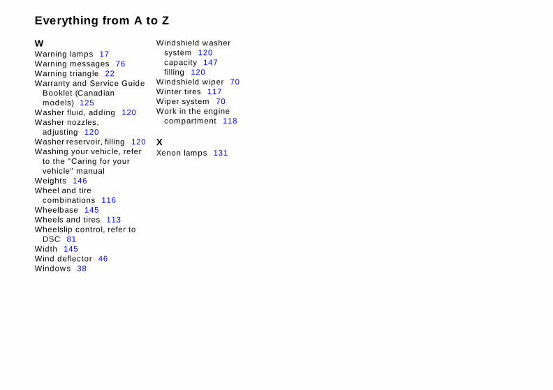
Everything from A to Z
W Warning lamps 1Warning messagWarning triangleWarranty and Se
Booklet (Canadmodels) 125
Washer fluid, addWasher nozzles,
adjusting 120 Washer reservoir
7 es 76 22
rvice Guide ian
ing 120
, filling 120 hicle, refer
Windshield washer system 120 capacity 147 filling 120
Windshield wiper 70 Winter tires 117 Wiper system 70 Work in the engine
compartment 118
X
Washing your veto the "Caring for your vehicle" manual
Weights 146 Wheel and tire
combinations 116 Wheelbase 145 Wheels and tires 113 Wheelslip control, refer to
DSC 81 Width 145 Wind deflector 46 Windows 38
Xenon lamps 131

Refueling
To ensure that you always have conve-nient access to all essential information when you stop for fuel, we recommend that you fill out the adjoining chart by entering the data that apply to your vehicle.Consult the index for individual specifi-cations.
Fuel
Please enter your preferred fuel here.
Engine oil
The oil volume between the two markson the dipstick corresponds to approx.
Designation
Quality
mer tires Winter tires
Rear Front Rear
1.1 US quarts (1 liter).
Tire inflation pressures
Up to 2 passengers
4 passengers plus luggage
Sum
Front

The UltimateDriving Machine
01
41
01
56
19
0ue
More about BMW
bmwusa.com

3 C
on
vert
ible
US
-En