for vehicle-mounted elevating and rotating aerial devices · pdf fileamerican national...
TRANSCRIPT

ANSI/SIA A92.2 – 2009
for
Vehicle-Mounted Elevating and Rotating Aerial Devices
American National Standards Institute 11 West 42nd Street New York, New York 10036
Licensed to Kirk Flickinger. ANSI order X_217606. Downloaded 3/23/2011 3:09 PM. Single user license only. Copying and networking prohibited.

Licensed to Kirk Flickinger. ANSI order X_217606. Downloaded 3/23/2011 3:09 PM. Single user license only. Copying and networking prohibited.

Date of Publication: September 1, 2009 This Standard will become effective March 1, 2010. This Standard was approved by the American National Standards Institute on July 14, 2009 The design and manufacturing requirements of this standard apply to all aerial platforms manufactured on or after the effective date. All other provisions of this standard apply to both new and existing units delivered by sale, lease, rental or for any form of beneficial use on or after the effective date. The effective date is established by the standards developer and not by the American National Standards Institute. This standard was developed under procedures accredited as meeting the criteria for American National Standards. The Consensus Committee that approved the standard was balanced to assure that individuals from competent and concerned interests have had an opportunity to participate. The proposed standard was made available for public review and comment which provides an opportunity for additional public input from industry, academia, regulatory agencies, and the public-at-large. The Scaffold Industry Association, Inc. (SIA) does not “approve,” “rate,” or “endorse” any item, construction, proprietary device or activity. The Scaffold Industry Association, Inc. (SIA) does not take any position with respect to the validity of any patent rights asserted in connection with any items mentioned in this document, and does not undertake to ensure anyone utilizing a standard against liability for infringement of any applicable Letters Patent, nor assume any such liability. Users of this standard are expressly advised that the determination of the validity of any such patent rights, and the risk of the infringement of such rights, is entirely their own responsibility. Participation by federal agency representative(s) or person(s) affiliated within the industry is not to be interpreted as government or industry endorsement of this standard. The Scaffold Industry Association, Inc. (SIA) accepts responsibility for only those interpretations issued in accordance with governing ANSI Essential Requirements which preclude the issuance of interpretations by individual volunteers.
Licensed to Kirk Flickinger. ANSI order X_217606. Downloaded 3/23/2011 3:09 PM. Single user license only. Copying and networking prohibited.

ANSI/SIA
A92.2-2009
AMERICAN NATIONAL STANDARD for VEHICLE-MOUNTED ELEVATING
AND ROTATING AERIAL DEVICES
Secretariat
Scaffold Industry Association, Inc. Approved July 14, 2009
American National Standards Institute, Inc
Licensed to Kirk Flickinger. ANSI order X_217606. Downloaded 3/23/2011 3:09 PM. Single user license only. Copying and networking prohibited.

AMERICAN NATIONAL STANDARD Approval of an American National Standard requires verification by ANSI that the requirements for due process, consensus, and other criteria for approval have been met by the standards developer. Consensus is established when, in the judgment of the ANSI Board of Standards Review, substantial agreement has been reached by directly and materially affected interests. Substantial agreement means much more that a simple majority, but not necessarily unanimity. Consensus requires that all views and objections be considered, and that a concerted effort be made toward their resolution. The use of American National Standards is completely voluntary; their existence does not in any respect preclude anyone, whether he has approved the standard or not, from manufacturing, marketing, purchasing, or using products, or procedures not conforming to the standards. The American National Standards Institute does not develop standards and will in no circumstances give an interpretation of any American National Standard. Moreover, no person shall have the right or authority to issue an interpretation of an American National Standard in the name of the American National Standards Institute. Requests for interpretations should be addressed to the secretariat or sponsor whose name appears on the title page of this standard. CAUTION NOTICE: This American National Standard may be revised or withdrawn any time. The procedures of the American National Standards Institute require that action be taken to reaffirm, revise, or withdraw this standard no later than five years from the date of approval. Purchasers of American National Standards may receive current information on all standards by calling or writing the American National Standards Institute. Published by Scaffold Industry Association, Inc. 400 Admiral Boulevard Kansas City, MO 64106 www.scaffold.org Copyright ©2009 by the Scaffold Industry Association, Inc. All rights reserved. No part of this publication may be reproduced in any form, in an electronic retrieval system or otherwise, without the prior written permission of the publisher.
Printed in the United States of America
Licensed to Kirk Flickinger. ANSI order X_217606. Downloaded 3/23/2011 3:09 PM. Single user license only. Copying and networking prohibited.

FOREWORD This foreword is not part of American National Standard for Vehicle-Mounted Elevating and Rotating Aerial Devices, ANSI/SIA A92.2-2009. This standard is one of a series on aerial platforms developed under the committee procedures of the American National Standards Institute. The A92 standards committee was organized by the Institute in 1948. The Scaffold Industry Association, Inc. serves as Secretariat. The primary objective of this standard is to prevent accidents associated with the use of Vehicle-Mounted Elevating and Rotating Aerial Devices by establishing requirements for design manufacture, installation, maintenance, performance, use and training. Interpretations and Suggestions for Improvement All inquiries requesting interpretation of the Committee’s approved American National Standards must be in writing and directed to the Secretariat. The A92 Committee shall approve the interpretation before submission to the inquirer. No one but the A92 Committee is authorized to provide any interpretation of this standard. The A92 Committee solicits comments on and criticism of the requirements of the standards. The standards will be revised from time to time where necessary or desirable, as demonstrated by the experience gained from the application of the standards. Proposals for improvement of this standard will be welcome. Proposals should be as specific as possible, citing the paragraph number(s), the proposed wording, and a detailed rationale for the proposal including any pertinent documentation. All requests for interpretation and all suggestions for improvement shall be forwarded in writing to the ASC A92 Committee, c/o Secretariat ~ Scaffold Industry Association, 400 Admiral Boulevard, Kansas City, MO 64106 This Standard was processed and approved for submittal to ANSI by Accredited Standards Committee Aerial Platforms, A92 Aerial Work Platforms. The ASC A92 committee approval of the standard does not necessarily imply that all committee members voted for its approval. At the time the ASC A92 committee approved this standard, the A92 Aerial Work Platforms Committee had the following members: Dave Merrifield, Chairman Lincoln L. Schoenberger, Vice-Chairman Acromet North America…………………………………………………………………………….Eric Schmidt AWPT…………………………………………………………………………………………….….Kevin O’Shea Alimak Hek, Inc…………………………………………………………………………………..Gregory Janda Altec HiLine, LLC………………………………………………………………………..………..Eric Lumberg Altec Industries……………………………………………………………………………………. Bryan Player American Rental Association…………………………………………………………………..Richard Stollery Arrowhead Aerial Products…………………………………………………………………..Sharon McCarty Arrowhead Product Development…………………………………………………………….Gary Werkhoven Association of Equipment Manufacturers………………………………………………………....Daniel Moss
Licensed to Kirk Flickinger. ANSI order X_217606. Downloaded 3/23/2011 3:09 PM. Single user license only. Copying and networking prohibited.

Beta Max, Inc……………………………………………………………………………………..Dennis Mannion Brewington & Company……………………………………………………………………John Brewington Jr. The Center for Construction Research……………………………………………..………..Michael McCann C.W. Wright Construction…………………………………………………………….……………Michael Stiles Diversified Inspections LLC……………………………………………………………………….Leland Bisbee Eckstine & Associates……………………………………………………………………………Dennis Eckstine Equipment Safety Consultants Inc………………………………………………...….Charles “Mark” Recard Equipment Technology LLC………………………………………………………………………….Brian Davis Evulich & Associates……………………………………………………………………………….Barris Evulich Florida Power & Light……………………………………………………………………………..Mike Paulson Ford Motor Company……………………………………………………………………….…….Ronald Bonner Fraco Products……………………………………………………………………………….Francois Villeneuve Genie Industries…………………………………………………………………………...……….Richard Curtin Global Rental Company……………………………………………………………………………Joshua Chard Haulotte Group……………………………………………………………………………….. Bernie Kiekebosch Hayden Enterprises……………………………………………………………………………..H.B. Hayden, Jr. Heath & Associates……………………………………………………………………………..Frederick Heath Hydro-Mobile, Inc……………………………………………………………………….……….Vincent DeQuoy Intercontinental Equipment Company LLC………………………………………….…….Gary McAlexander International Masonry Institute……………………………………………………….………Michael Kassman JLG Industries, Inc………………………………………………………………………….………Steven Forgas Kinectrics………………………………………………………………………………………………Ernest Jones Klimer Manufacturing………………………………………………………………………….. .. James Gordon Lee Electrical Construction……………………………………………………………………...…….John Cook Lift-A-Loft Corporation……………………………………………………………………….…..William Fulton MAT - 3 Inc……………………………………………………………………………………….……John Mlaker McDonough Construction…………………………………………………………………………..James Jensen MEC Aerial Work Platforms……………………………………………………………………….David White New York State Dept of Transportation………………………………………………….……Frank Bonesteel OEM Controls, Inc……………………………………………………………………...…Lincoln Schoenberger PCD, LLC…………………………………………………………………………………….…………Paul Young Phenix Technologies……………………………………………………………………….………….Mark Miller Pike Electric Inc………………………………………………………………………………..……Cliff Edwards Power Equipment Leasing Company, Inc……………………………………………………Tracy Schroeder Progress Energy, Carolina……………………………………………………………………..….David Benson Progress Energy, Florida………………………………………………………………………...Daniel Mueller Reynolds Engineering Servicing Inc………………………………………………………….Stephen Reynolds RSC Equipment Rental …………………………………………………………………………Kenneth Colonna Salt River Project………………………………………………………………………………..Raymond Ybarra Scaffold Industry Association…………………………………………………………………..David Merrifield Sexton's Equipment Rental, Inc……………………………………………………………...……..David Sexton Skyjack, Inc……………………………………………………………………………………..…….Brad Boehler Southern Company……………………………………………………………………………...…Douglas Bailey Sunbelt Rentals………………………………………………………………………………...……..Byron Adkins Terex Telelect…………………………………………………………………………………….…Elroy Severson The Von Corporation…………………………………………………………………..……Fred von Herrmann ThyssenKrupp Safway, Inc…………………………………………………………………………… Ted Beville Time Manufacturing Company……………………………………………………….…………James Christian United Rentals…………………………………………………………………………………………. Heidi Rawe
Licensed to Kirk Flickinger. ANSI order X_217606. Downloaded 3/23/2011 3:09 PM. Single user license only. Copying and networking prohibited.

USDOL/OSHA…………………………………………………………………………...…………Garvin Branch UpRight Powered Access………………………………………………………………….…….Nate Woodsmith Vollmer-Gray Engineering…………………………………………………………………..……..Paul Guthron Waco Boom Company………………………………………………………………………….. Jonathan Woods Xtreme Manufacturing……………………………………………………………………. Richard Hoffelmeyer At the time the ASC A92 committee approved this standard, the A92.2 Subcommittee on Vehicle-Mounted Elevating and Rotating Aerial Devices had the following members: Gary A. McAlexander, Chairman Douglas Bailey Michael Barrett Keith Beaucoudray Robert Borer Garvin Branch John Brewington, Jr. Randall Breyer Joshua Chard James Christian John Cook, Jr. Al Courchesne Brian Davis Cliff Edwards Richard Hoffelmeyer Chris Jeans
Ernest Jones Sharon McCarty David Merrifield Mark Miller John Mlaker Michael Paulson Stephen Reynolds, P.E. Tracy Schroeder Elroy Severson Bob Simon David Skarshaug, P.E. Michael Stiles Joe Vanderlugt Fred von Herrmann Gary Werkhoven Raymond Ybarra
Licensed to Kirk Flickinger. ANSI order X_217606. Downloaded 3/23/2011 3:09 PM. Single user license only. Copying and networking prohibited.

1. Scope, Purpose, Requirements, and Application ............................................................ 1 1.1 Scope. ............................................................................................................................ 14 1.1.1 Equipment Covered ................................................................................................. 14 1.1.2 Equipment Not Covered ........................................................................................... 14 1.3 Requirements. ................................................................................................................ 14 1.4 Application. ................................................................................................................... 14 2. Referenced and Related Standards ............................................................................... 15 2.1 Referenced Standards .................................................................................................... 15 2.2 Related Standards .......................................................................................................... 15 3. Definitions ..................................................................................................................... 16 4. Design Requirements ..................................................................................................... 18 4.1 Basic Principles. ............................................................................................................ 18 4.2 Structural Safety Factors ................................................................................................ 18 4.3 Controls. ........................................................................................................................ 19 4.3.1 General. .................................................................................................................... 19 4.3.2 Upper Controls ......................................................................................................... 19 4.3.3 Lower Controls ......................................................................................................... 19 4.3.4 Emergency Stop.. ...................................................................................................... 19 4.3.5 Outrigger Controls .................................................................................................... 19 4.3.6 Winch Control .......................................................................................................... 19 4.4 Travel Securing Device.................................................................................................. 19 4.4.1 Ladder Securing Device ............................................................................................ 19 4.4.2 Boom Securing Device ............................................................................................. 19 4.4.3 Platform Security ...................................................................................................... 19 4.5 Stability. ........................................................................................................................ 19 4.5.1 Stability on Level Surfaces........................................................................................ 19 4.5.2 Stability on Slopes. ................................................................................................... 19 4.5.3 Effects of Stability Test. ............................................................................................ 20 4.5.4 Slope Indicator .......................................................................................................... 20 4.5.5 Outrigger Interlock Device. ....................................................................................... 20 4.6 Bursting Safety Factors .................................................................................................. 20 4.7 Hydraulic Cylinders ....................................................................................................... 21 4.7.1 Safety Factors. .......................................................................................................... 21 4.7.2 Column Load. ........................................................................................................... 21 4.7.3 External Load. .......................................................................................................... 21 4.7.4 Threaded Components. ............................................................................................. 21 4.7.5 Hydraulic Pressure Rise. ........................................................................................... 21 4.8 Platform or Load Motion ............................................................................................... 21 4.8.1 System Protection ..................................................................................................... 21 4.8.2 Platform Creep. ......................................................................................................... 21 4.9 Platforms. ...................................................................................................................... 21 4.9.1 Guardrail System ...................................................................................................... 21 4.9.2 Ladder Type.............................................................................................................. 21 4.9.3 Folding Type Floors. ................................................................................................. 21 4.9.4 Anchorage(s) for Personal Fall Protection ................................................................. 22 4.9.4.1 Location ................................................................................................................ 22 4.9.4.2 Markings ............................................................................................................... 22 4.9.4.3 Strength Requirement. ........................................................................................... 22 4.9.4.4 Connector Requirement ......................................................................................... 22 4.9.4.5 Surface. ................................................................................................................. 22
Licensed to Kirk Flickinger. ANSI order X_217606. Downloaded 3/23/2011 3:09 PM. Single user license only. Copying and networking prohibited.

4.9.4.6 Pinch restriction .................................................................................................... 22 4.9.5 Buckets or Baskets .................................................................................................... 22 4.9.5.1 Non-insulating buckets or baskets designed for use with insulating liners .............. 22 4.9.5.2. Non-insulating buckets or baskets designed for use without liners . ...................... 22 4.9.5.3 Insulating baskets or buckets. ................................................................................ 22 4.9.5.4 Dimensions ........................................................................................................... 22 4.10 Markings ..................................................................................................................... 22 4.10.1 Type of Markings:................................................................................................... 22 4.10.2 Design of Markings ................................................................................................. 22 5. Electrical Systems, Devices and Test Procedures ......................................................... 22 5.1 Electrical Specifications. ................................................................................................ 22 5.1.1 Insulation .................................................................................................................... 22 5.1.2 Insulating Aerial Device Categories .......................................................................... 23 5.2 Electrical Requirements ................................................................................................. 23 5.2.1 Insulating Systems .................................................................................................... 23 5.2.1.1 Insulating Hydraulic Hoses. .................................................................................. 23 5.2.2 Vacuum Prevention Systems. .................................................................................... 23 5.2.3 Lower Test Electrode System for insulating Aerial Devices ...................................... 23 5.2.3.1 Conductive Bands ................................................................................................. 23 5.2.3.2 Conductive Connections........................................................................................ 24 5.2.3.3 Electrical Monitoring Circuit. ................................................................................ 24 5.2.4 Gradient Control Devices & Conductive Shield(s) .................................................... 24 5.2.4.1 Gradient Control Devices ...................................................................................... 24 5.2.4.2 Conductive Shield(s). ............................................................................................ 24 5.2.5 Chassis Insulating System ......................................................................................... 24 5.2.6 Upper Controls ......................................................................................................... 24 5.3 Electrical Tests for Insulating Aerial Devices................................................................. 25 5.3.1 Design Voltage Test. ................................................................................................. 25 5.3.2 Qualification Test ..................................................................................................... 25 5.3.3 Quality Assurance Test. ............................................................................................ 25 5.3.4 Periodic Electrical Test. ............................................................................................ 25 5.3.5 Before Use (Frequent) Test. ...................................................................................... 25 5.4 Electrical Test Procedures .............................................................................................. 25 5.4.1 General ..................................................................................................................... 25 5.4.2 Design, Qualification, and Quality Assurance Test Procedures.................................. 25 5.4.2.1 Test Procedures for Category A & B Aerial Devices ............................................. 25 5.4.2.2 Test Procedures for Category C Aerial Devices ..................................................... 26 5.4.2.3 Test Procedures for Aerial Ladders and Vertical Towers, with Insulating Boom Sections ................................................... 26 5.4.2.4 Test Procedures for Chassis Insulating Systems .................................................... 26 5.4.2.5 Test Procedures for Insulating Liners .................................................................... 26 5.4.2.6 Confirmation Test of Upper Control Components with High Electrical Resistance.. ........................................................................... 26 5.4.2.7 Test Procedures for Extensible Boom Aerial Devices with Permanent Electrodes... ................................................................................. 26 5.4.3 Periodic/Maintenance Test Procedures. ..................................................................... 26 5.4.3.1 Test Procedures for Category A and B Insulating Aerial Devices .......................... 26 5.4.3.2 Test Procedures for Category C Aerial Devices ..................................................... 27 5.4.3.3 Test Procedures for Aerial Ladders and Vertical Towers with Insulating Boom Sections.............................................. 28
Licensed to Kirk Flickinger. ANSI order X_217606. Downloaded 3/23/2011 3:09 PM. Single user license only. Copying and networking prohibited.

5.4.3.4 Test Procedures for Chassis Insulating Systems .................................................... 28 5.4.3.5 Test Procedures for Insulating Liners .................................................................... 28 5.4.3.6 Confirmation Test of Upper Control Components with High Electrical Resistance ............................................................................. 28 5.4.3.7 Test Procedures for Extensible Boom Aerial Devices without Permanent Electrodes or with Electrodes and Tested as a Category C Device. ......................................... 28 5.5 Electrical Test Equipment. ............................................................................................. 28 5.6 Electrical Certification ................................................................................................... 28 6. Responsibilities of Manufacturers ................................................................................ 29 6.1 General Responsibilities ................................................................................................ 29 6.2 Specifications ................................................................................................................ 29 6.2.1 Vehicle Specifications............................................................................................... 29 6.2.2 Aerial Device Specifications ..................................................................................... 29 6.2.2.1 General ................................................................................................................. 29 6.2.2.2 Capacity ................................................................................................................ 29 6.2.2.3 Rated Platform Height ........................................................................................... 29 6.2.2.4 Platform Reach. .................................................................................................... 29 6.2.2.5 Multiple Configurations ........................................................................................ 29 6.2.2.6 Design Voltage. .................................................................................................... 30 6.2.2.7 Qualification Voltage. ........................................................................................... 30 6.3 Quality Assurance. ......................................................................................................... 30 6.4 Manuals ......................................................................................................................... 30 6.5 Markings. ...................................................................................................................... 30 6.5.1 Application of Markings. .......................................................................................... 30 6.5.2 Identification Markings. ............................................................................................ 30 6.5.3 Operational Markings. .............................................................................................. 30 6.5.4 Instructional Markings .............................................................................................. 30 6.6 Mechanical Tests and Inspection. ................................................................................... 31 6.6.1 Operational Tests ...................................................................................................... 31 6.6.2 Visual Inspection. ..................................................................................................... 31 6.7 Electrical Tests .............................................................................................................. 31 6.8 Installation Instructions .................................................................................................. 31 6.9 Welding. ........................................................................................................................ 31 6.10 Training and Training Materials ................................................................................... 31 7. Responsibilities of Dealers and Installers ..................................................................... 31 7.1 General Responsibilities ................................................................................................ 31 7.2 Vehicle Specifications ................................................................................................... 31 7.3 Vehicle Weight Distribution .......................................................................................... 31 7.4 Manuals. ........................................................................................................................ 32 7.5 Installations. .................................................................................................................. 32 7.6 Quality Assurance. ......................................................................................................... 32 7.7 Weldings. ...................................................................................................................... 32 7.8 Training. ........................................................................................................................ 32 7.8.1 Dealer or Installer as User. .......................................................................................... 32 7.9 Maintenance Training. ................................................................................................... 32 8. Responsibilities of Owners ............................................................................................ 32 8.1 General Responsibilities ................................................................................................ 32 8.2 Inspection and Testing Classifications ........................................................................... 32 8.2.1 Initial Inspection and Test. ........................................................................................ 32 8.2.2 Regular Inspection and Tests..................................................................................... 32
Licensed to Kirk Flickinger. ANSI order X_217606. Downloaded 3/23/2011 3:09 PM. Single user license only. Copying and networking prohibited.

8.2.3 Frequent Inspection and Test: ................................................................................... 33 8.2.4 Periodic Inspection or Test ........................................................................................ 33 8.2.5 Post Event Inspection or Test. ................................................................................... 34 8.3 Inspection and Test Records .......................................................................................... 34 8.3.1 Frequent .................................................................................................................... 34 8.3.2 Periodic. ................................................................................................................... 35 8.4 Maintenance. ................................................................................................................. 35 8.4.1 Maintenance Training. .............................................................................................. 35 8.4.2 Weldings................................................................................................................... 35 8.5 Modifications................................................................................................................. 35 8.5.1 Alterations. ............................................................................................................... 35 8.6 Weight Distribution. ...................................................................................................... 35 8.7 Transfer of Ownership ................................................................................................... 35 8.8 Markings. ...................................................................................................................... 35 8.9 Parts. ............................................................................................................................. 35 8.10 Safety Bulletins............................................................................................................ 35 8.11 Manuals. ...................................................................................................................... 35 8.12 Training, Retraining, and Familiarization of Operators................................................. 35 8.12.1 General Training. ...................................................................................................... 35 8.12.2 Retraining. .............................................................................................................. 36 8.12.3 Familiarization ........................................................................................................ 36 8.13 Owner as a Lessor. ....................................................................................................... 36 9. Responsibilities of Users ................................................................................................ 36 9.1 General Responsibilities ................................................................................................ 36 9.2 Personnel. ...................................................................................................................... 36 9.3 Training, Retraining, and Familiarization of Operators .................................................. 36 9.3.1 General Training: ...................................................................................................... 36 9.3.2 Retraining ................................................................................................................. 37 9.3.3 Familiarization .......................................................................................................... 37 9.3.4 Proof of Training ...................................................................................................... 37 9.4 Application. ................................................................................................................... 37 9.5 Electrical Hazards. ......................................................................................................... 37 9.6 Bare-Hand Work............................................................................................................ 37 9.7 Lower Controls. ............................................................................................................. 37 9.8 Manufacturer’s Safety Bulletins. .................................................................................... 37 10. Responsibilities of Operators ...................................................................................... 37 10.1 General Responsibilities. ............................................................................................. 37 10.2 Personnel ..................................................................................................................... 37 10.3 Operation. .................................................................................................................... 37 10.4 Work Platform.. ........................................................................................................... 37 10.5 Brakes.......................................................................................................................... 37 10.6 Loading. ...................................................................................................................... 37 10.7 Alterations ................................................................................................................... 37 10.8 Observations ................................................................................................................ 37 10.8.1 Pre-start Inspection ................................................................................................. 38 10.9 Worksite ...................................................................................................................... 38 10.10 Precautions ................................................................................................................ 38 10.11 Mobile Operation ....................................................................................................... 38 10.11.1 Driver Precautions ................................................................................................ 38 10.12 Training, Retraining, and Familiarization of Operators ............................................... 39
Licensed to Kirk Flickinger. ANSI order X_217606. Downloaded 3/23/2011 3:09 PM. Single user license only. Copying and networking prohibited.
10.12.1 General Training ................................................................................................... 39 10.12.2 Retraining. ............................................................................................................ 39 10.12.3 Familiarization ...................................................................................................... 39 10.13 Electrical Hazard ....................................................................................................... 39 11. Responsibilities of Lessors or Lessees ......................................................................... 39 11.1 General Responsibilities .............................................................................................. 39 11.1.1 Lessor or Lessee as Dealer or Installer. ................................................................... 39 11.1.2 Lessor or Lessee as Owner ...................................................................................... 39 11.1.3 Lessor or Lessee as User. ........................................................................................ 39 11.1.4 Lessor or Lessee as Operator ................................................................................... 39 11.2 Ownership Responsibilities. ......................................................................................... 39 11.3 Obligations. ................................................................................................................. 40 11.3.1 Inspection and Test. ................................................................................................ 40 11.3.2 Responsibilities ....................................................................................................... 40 11.4 Training. ...................................................................................................................... 40 11.4.1 General Training ..................................................................................................... 40 11.4.2 Familiarization ........................................................................................................ 40 11.5 Communications. ......................................................................................................... 40 11.6 Use of Brokers. ............................................................................................................ 40 12. Responsibilities of Brokers .......................................................................................... 40 12.1 Broker Involved In a Sale ............................................................................................ 40 12.2 Broker Involved In a Lease .......................................................................................... 41
TABLES Table 1: Design, Quality Assurance and Qualification Test Values ...................................... 42 Table 2: Periodic Electrical Test Values ............................................................................. 44 Table 3: In-Field Tests ......................................................................................................... 45
FIGURES Figure 1: Dielectric Test Configuration for Category A & B Aerial Devices ........................ 46 Figure 2: Dielectric Test Configuration for Category A & B Aerial Devices ........................ 47 Figure 2A: Details of Lower Test Electrode Assembly & Conductive Shield ....................... 48 Figure 3: Dielectric Test Configuration for Category C Aerial Devices ................................ 49 Figure 3A: Optional Dielectric Test Configuration for Category C Aerial Devices .............. 50 Figure 4: Dielectric Test Configuration for Chassis Insulating Systems ............................... 51 Figure 4A: Suggested Shunting Arrangement for Chassis Insulating System ....................... 52 Figure 5: Boom Positions for Dielectric Test of Extensible Insulating Aerial Devices .......... 53 Figure 6: Typical Bonding Arrangements for Category A Aerial Devices ............................ 54 Figure 7: Confirmation Test of Upper Control Components w/High Electrical Resistance ... 55 Figure 8: Recommended Identification Plate Format ........................................................... 56
APPENDICES Appendix A – Electrical Test Terminology and Clarification ............................................... 57 Appendix B – DC Application ............................................................................................. 57 Appendix C – Application and Uses of Aerial Devices ....................................................... 58 Appendix D – Electrical Tests for Aerial Devices, Insulated Platforms and Insulated Ladders for AC Application ................................................... 58 Appendix E – Electircal Tests for Aerial Devices Built in Compliance to Earlier Editions of this Standard. ................................................................... 58 Appendix F – Precautions for Use of Aerial Devices on or near Energized Apparatus ....... 59 Appendix G – Recommended Identification & Instruction Symbols for Control Function …63
Licensed to Kirk Flickinger. ANSI order X_217606. Downloaded 3/23/2011 3:09 PM. Single user license only. Copying and networking prohibited.
14
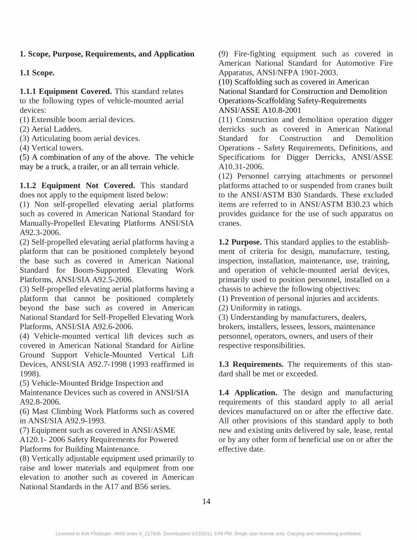
1. Scope, Purpose, Requirements, and Application 1.1 Scope. 1.1.1 Equipment Covered. This standard relates to the following types of vehicle-mounted aerial devices: (1) Extensible boom aerial devices. (2) Aerial Ladders. (3) Articulating boom aerial devices. (4) Vertical towers. (5) A combination of any of the above. The vehicle may be a truck, a trailer, or an all terrain vehicle. 1.1.2 Equipment Not Covered. This standard does not apply to the equipment listed below: (1) Non self-propelled elevating aerial platforms such as covered in American National Standard for Manually-Propelled Elevating Platforms ANSI/SIA A92.3-2006. (2) Self-propelled elevating aerial platforms having a platform that can be positioned completely beyond the base such as covered in American National Standard for Boom-Supported Elevating Work Platforms, ANSI/SIA A92.5-2006. (3) Self-propelled elevating aerial platforms having a platform that cannot be positioned completely beyond the base such as covered in American National Standard for Self-Propelled Elevating Work Platforms, ANSI/SIA A92.6-2006. (4) Vehicle-mounted vertical lift devices such as covered in American National Standard for Airline Ground Support Vehicle-Mounted Vertical Lift Devices, ANSI/SIA A92.7-1998 (1993 reaffirmed in 1998). (5) Vehicle-Mounted Bridge Inspection and Maintenance Devices such as covered in ANSI/SIA A92.8-2006. (6) Mast Climbing Work Platforms such as covered in ANSI/SIA A92.9-1993. (7) Equipment such as covered in ANSI/ASME A120.1- 2006 Safety Requirements for Powered Platforms for Building Maintenance. (8) Vertically adjustable equipment used primarily to raise and lower materials and equipment from one elevation to another such as covered in American National Standards in the A17 and B56 series.
(9) Fire-fighting equipment such as covered in American National Standard for Automotive Fire Apparatus, ANSI/NFPA 1901-2003. (10) Scaffolding such as covered in American National Standard for Construction and Demolition Operations-Scaffolding Safety-Requirements ANSI/ASSE A10.8-2001 (11) Construction and demolition operation digger derricks such as covered in American National Standard for Construction and Demolition Operations - Safety Requirements, Definitions, and Specifications for Digger Derricks, ANSI/ASSE A10.31-2006. (12) Personnel carrying attachments or personnel platforms attached to or suspended from cranes built to the ANSI/ASTM B30 Standards. These excluded items are referred to in ANSI/ASTM B30.23 which provides guidance for the use of such apparatus on cranes. 1.2 Purpose. This standard applies to the establish-ment of criteria for design, manufacture, testing, inspection, installation, maintenance, use, training, and operation of vehicle-mounted aerial devices, primarily used to position personnel, installed on a chassis to achieve the following objectives: (1) Prevention of personal injuries and accidents. (2) Uniformity in ratings. (3) Understanding by manufacturers, dealers, brokers, installers, lessees, lessors, maintenance personnel, operators, owners, and users of their respective responsibilities. 1.3 Requirements. The requirements of this stan-dard shall be met or exceeded. 1.4 Application. The design and manufacturing requirements of this standard apply to all aerial devices manufactured on or after the effective date. All other provisions of this standard apply to both new and existing units delivered by sale, lease, rental or by any other form of beneficial use on or after the effective date.
Licensed to Kirk Flickinger. ANSI order X_217606. Downloaded 3/23/2011 3:09 PM. Single user license only. Copying and networking prohibited.

15
2. Referenced and Related Standards
2.1 Referenced Standards. This standard is intended to be used in conjunction with the following standards.
ANSI/IEEE C2-2007 Part 4, National Electrical Safety Code. ANSI/ASSE Z359.1-2007, Safety Requirements for Personal Fall Arrest Systems, Subsystems and Components ANSI/ASSE Z535.1-2006, Safety Color Code. ANSI/ASSE Z535.3-2002, Criteria for Safety Symbols. ANSI/ASSE Z535.4-2002, Product Safety Signs and Labels. AWS D1.1-2006, Structural Welding Code - Steel. AWS D1.2-2003, Structural Welding Code – Aluminum. AWS B1.10-1999, Guide for the Non-Destructive Examination of Welds. IEEE/ASTM SI 10-2002 Standard for Use of the International System of Units (SI): The Modern Metric System IEEE Std. 4-1995, Standard Techniques for High Voltage Testing IEEE Std. 4a-2001, Amendment to IEEE Standard Techniques for High-Voltage Testing Federal Motor Vehicle Safety Standards SAE J517 Mar 2006, Hydraulic Hose 2.2 Related Standards. The standards listed here are for information only and are not essential for the completion of the requirements of this standard: ANSI/SIA A92.3-2006, Manually Propelled
Elevating Work Platforms. ANSI/SIA A92.5-2006, Boom-Supported Elevating Work Platforms. ANSI/SIA A92.6-2006, Self-Propelled Elevating Work Platforms. ANSI/SIA A92.7-1998 (1993 reaffirmed in 1998), Airline Ground Support Vehicle-Mounted Vertical Lift Devices. ANSI/SIA A92.8 -2006, Vehicle-Mounted Bridge Inspection and Maintenance Devices. ANSI/SIA A92.9-1993, Mast-Climbing Work Platforms ANSI/SIA A92.10-2008, Transport Platforms ANSI/ASME A120.1-2006, Safety Requirements for Powered Platforms for Building Maintenance. ANSI/ASSE A10.8-2001, Construction and Demolition Operations – Scaffolding - Safety Requirements. ANSI/ASSE A10.31-2006, Construction and Demolition Operations - Safety Requirements, Definitions, and Specifications for Digger Derricks. ANSI/ASME B30.5-2004, Mobile and Locomotive Cranes. ANSI/NFPA 1901-2003, Automotive Fire Apparatus. ANSI/ISA Z133.1-2006 Tree Care Operations - Pruning, Trimming, Repairing, Maintaining, and Removing Trees, and Cutting Brush - Safety Requirements. ASTM E114-2005, Ultrasonic Pulse-Echo Straight Beam Examination by Contact Method. ASTM E165-09, Standard Test Method for Liquid Penetrant Examination
Licensed to Kirk Flickinger. ANSI order X_217606. Downloaded 3/23/2011 3:09 PM. Single user license only. Copying and networking prohibited.

16
ASTM E709-08 Standard Guide for Magnetic Particle Examination ASTM F914-03, Acoustic Emission Testing of Insulated and Non-Insulated Aerial Personnel Devices without Supplemental Load Handling Attachments ASTM F1430-03, Acoustic Emission Testing of Insulated and Non-Insulated Aerial Personnel Devices with Supplemental Load Handling Attachments CAN/CSA C225-00 Vehicle-Mount Aerial Devices SAE J343 Jan 2004, Test and Test Procedures for SAE 100R Series Hydraulic Hose and Hose Assemblies 3. Definitions Aerial device. Any device, extensible, articulating, or both, which is primarily designed and used to position personnel. The device may also be used to handle material, if designed and equipped for that purpose. Aerial ladder. An aerial device consisting of a single or multiple-section rung ladder with or without a platform at the top. Anchorage(s). A secure point of attachment to be used with personal fall protection (PFP) equipment. Articulating-boom aerial device. An aerial device with two or more hinged boom sections. Authorized personnel. A person(s) approved or assigned to perform a specific type of duty(s) or to be at a specific location(s) at the job site. Bare-hand work. A technique of performing live line maintenance on energized conductors and equipment whereby one or more authorized persons work directly on an energized part after having been raised and bonded to the energized conductors or equipment. Broker. An independent business entity or person that arranges a lease or transfer of ownership of an aerial device, but is not the Lessor or does not make the actual transfer of ownership of the aerial device. Certification. A written statement, signed by a qualified person, verifying that the design,
manufacture, installation and testing of the aerial device is in accordance with this standard. Chassis. A vehicle on which the aerial device is mounted such as a truck, a trailer or an all-terrain vehicle. Chassis insulating system. An insulating system of dielectric components installed between the chassis and the upper insulating boom. Conductive shield (guard ring). A device used to shield the lower test electrode system from capacitive coupling. Dealer. A person or entity who buys (from a manufacturer or others) and who generally sells, rents, leases, and services aerial devices. Ductile materials. Materials that have a minimum elongation at failure of 10% in a gauge length of 2 inches (51 mm) on a standard test specimen. Equivalent entity. An organization, agency, or indi-vidual who, by possession of an appropriate technical degree, certificate, professional standing, or skill, and who, by knowledge, training, and experience, has demonstrated the ability to deal with the problems relating to the subject matter, the work, or the project. Extensible-boom aerial device. An aerial device, except the aerial ladder type, with a telescopic or extensible boom. Flashover. A disruptive electrical discharge at the surface of electrical insulation or in the surrounding medium, which may or may not cause permanent damage to the insulation. Guard rail system. A vertical barrier intended to protect personnel from falling to lower levels. Gradient control device. A device(s) at the upper end of an insulating boom that reduces electrical stress level(s) below that considered to be disruptive (commonly referred to as a “corona ring”). Instability. A condition of a mobile unit in which the sum of the moments tending to overturn the unit is equal to or exceeds the sum of the moments tending to resist overturning. Installer. A person(s) or entity who mounts an aerial device on a vehicle. Insulated. Separated from other conducting surfaces by a dielectric substance or air space offering a high resistance to the passage of electrical current and to disruptive discharge through the substance or space.
Licensed to Kirk Flickinger. ANSI order X_217606. Downloaded 3/23/2011 3:09 PM. Single user license only. Copying and networking prohibited.

17
When any object is said to be insulated, it is understood to be insulated in a manner suitable for the conditions to which it is subjected. Insulating aerial device. An aerial device with dielectric components designed and tested to meet the specific electrical insulating rating consistent with the manufacturer’s identification plate. Insulating liner. An aerial device basket or bucket insert made of material having a high dielectric strength. Lessee. A person(s) or entity to whom an aerial device is provided by lease, rental, loan, or other arrangement. A lessee may also be a dealer, user or operator. Lessor. A person(s) or entity who leases, rents, loans, or otherwise provides an aerial device to another party for the beneficial use of that party (the lessee). A lessor may also be a dealer, installer, manufacturer, owner, lessee, user or operator. Manual force. The load produced by person(s) in the platform working on a stationary object, external to the aerial device. These loads are generally horizontal in nature, and applied at the upper periphery of the platform. Manual of Responsibilities. A document containing definitions (Section 3) and the requirements including dielectric testing (Section 5) and the referenced Tables and Figures mandated in this Standard for the following entities: Dealers and Installers (Section 7), Owners (Section 8), Users (Section 9), Operators (Section 10), Lessors (Section 11), Lessees (Section 11) and Brokers (Section 12). Manufacturer. A person or entity who makes, builds, or produces an aerial device. Minimum Approach Distance (MAD). The closest distance a qualified person is permitted to approach either an energized or a grounded object, as applicable for the work method being used. Mobile operation. The uncradled use of the aerial device while the mobile unit is traveling. Mobile unit. A combination of an aerial device, its chassis, and related equipment. Non-destructive examination (NDE). The examination by various means of devices or their components without alteration of the original components, so that they may function as before. These include, but are not limited to, visual
inspection (VT), acoustic emissions (AE), magnetic particle (MT), liquid penetration (PT), ultrasonic (UT), and dielectric (DT). Non-ductile materials. Materials that have an elongation at failure of less than 10% in a gauge length of 2 inches (51 mm) on a standard test specimen. Operator. A person trained, authorized, and engaged in the operation of the aerial device. Override. The takeover of aerial device movement and winch control functions at the platform controls by the activation of the lower control station controls. Owner. A person or entity who has possession of an aerial device by virtue of proof of purchase. Platform. The personnel-carrying component of an aerial device, such as a bucket, basket, stand, or equivalent. Platform capacity. The component of rated load capacity consisting of the weight of personnel and all items carried on or in the platform including the liner. Platform height. The distance measured at maxi-mum elevation from the bottom of the platform to the ground. Platform reach. The distance measured horizontally from the centerline of the pedestal (rotation) to the outer edge (rail) of the platform. Qualified person. A person who, by possession of an appropriate technical degree, certificate, profes-sional standing, or skill, and who, by knowledge, training, and experience, has demonstrated the ability to deal with problems relating to the subject matter, the work, or the project. Rated load capacity (platform capacity + supple-mental capacity). The maximum loads, specified by the manufacturer, which can be lifted by the aerial device through the specified range of boom elevation and extension with specified options installed and in consideration of stability requirements. Unless oth-erwise specified, these loads are vertical. Rated platform height. The distance measured at maximum elevation from the bottom of the platform to the ground based on a chassis height of 40 inches (1 meter). Shall. The use of the word “shall” is to be under-stood as mandatory, and having the same effect as
Licensed to Kirk Flickinger. ANSI order X_217606. Downloaded 3/23/2011 3:09 PM. Single user license only. Copying and networking prohibited.

18
“must” and “will”. Should. The use of the word “should” is to be understood as advisory, and having the same effect as “recommended” Stability. A condition of a mobile unit in which the sum of the moments which tend to overturn the unit is less than the sum of the moments tending to resist overturning. Stowed position (of the boom). The position of the boom on the vehicle where it is intended for non-use and/or transport. Supplemental capacity. The component of rated load capacity which may be fixed directly to the boom(s), or to load carrying attachments on the aerial device. Telescopic aerial device. See extensible-boom aerial device. User. A person(s) or entity who has care, control and custody of the aerial device. This person(s) or entity may also be the employer of the operator, a dealer, an installer, lessee, lessor or operator. Vehicle. A carrier for an aerial device (see chassis). Vertical tower. Any aerial device with a platform which can be raised along a vertical axis. Voltage. Rated line voltage: The nominal phase to phase voltage at which electrical systems are rated. Design voltage: The maximum rated line voltage for which the aerial device has been designed, and for which it can be qualified. Qualification voltage: The rated line voltage for which the aerial device has been actually tested. 4. Design Requirements
4.1 Basic Principles. The design and manufacture of the aerial device shall comply with the principles outlined in this standard. Sound engineering principles and reasonable assumptions consistent with all data regarding intended use and anticipated environment shall be applied in the design of aerial devices, with due respect to the fact that the units carry personnel. 4.2 Structural Safety Factors. Structural elements of the aerial device which support the platform, the platform itself, and material carrying attachments, if
so equipped, shall have a design stress as stated herein. The calculated design stress shall be based on the combined rated load capacity and weight of the support structure. For ductile materials, the design stress shall not be more than 50% of minimum yield strength of the material. For non-ductile material(s) and fiberglass reinforced plastic, the design stress shall not be more than 20% of the minimum ultimate strength of the material. For chains, wire rope assemblies and components rated according to ultimate strengths, the design loads shall not be more than 20% of the ultimate strength. Some components that have been qualified by test and or acceptable design criteria shall be considered as providing equivalent levels of safety in accordance with this section. Examples include gears, gear boxes, threaded fasteners and bearings. For these components, the original manufacturer’s ratings shall not be exceeded. The analysis shall consider the effects of the following: -Stress concentrations -Dynamic loadings -Operation on a 5 degree slope -Ambient temperatures for which the aerial device has been designed. -Loads produced during travel and mobile operations. -Loads produced from wind. -Loads produced from manual forces applied at the upper periphery of the platform (Minimum value shall be 50 pounds applied horizontally for aerial devices designed to carry one person and 100 pounds applied horizontally for aerial devices designed to carry more than one person.) -Loads that include column loading
(Maximum load on any column at the rated load capacity of the aerial device in any position shall not exceed 50% of the load that would cause deformation.)
Licensed to Kirk Flickinger. ANSI order X_217606. Downloaded 3/23/2011 3:09 PM. Single user license only. Copying and networking prohibited.

19
4.3 Controls. 4.3.1 General. Aerial devices shall have both upper and lower controls for boom positioning. All controls shall be clearly identified as to their func-tion and protected from damage and unintentional actuation. The boom positioning and material carrying attachment controls shall return to their neutral position when released by the operator. 4.3.2 Upper Controls. Upper controls shall be in or beside the platform and readily accessible to the operator. On a two-platform aerial device, control operation from either platform shall be accomplished with reasonable ease and without the need to disengage personal fall protection equipment. In order to protect against unintentional actuation of the boom positioning controls at the platform, the use of an unlocking or enabling device shall precede the use of the control itself. The unlocking or enabling device shall return to the locked or disabled position when the control is released by the operator. The unlocking or enabling device may be incorpo-rated into each control. 4.3.3 Lower Controls. Lower controls shall be readily accessible in all boom positions and shall provide a means to override the boom positioning upper controls provided the upper control system is intact. The override mode shall maintain its function while unattended. The lower controls of insulating aerial devices shall be designed in such a manner that an operator is not placed in the electrical path between the aerial device and the ground. 4.3.4 Emergency Stop. An additional control shall be provided at the platform and at the lower controls to affect an emergency stop of the powered upper control functions. These controls shall be per-manently marked and shall not require continuous actuation for a stop condition. At the lower controls, the override control may be used as an emergency stop provided it is clearly identified as an “emergency stop”.
4.3.5 Outrigger Controls. When the aerial device is equipped with outrigger controls, these controls shall be guarded to protect against unintentional operation, and shall return to neutral when released by the operator. The controls shall be located so that the operator can see the outrigger being operated. 4.3.6 Winch Control. If the aerial device is equipped with a material handling winch at the upper boom, it shall have both upper and lower controls to operate the winch. The lower control shall provide for overriding the upper control provided the upper control system is intact. The lower winch control shall be accessible from the lower boom positioning controls.
4.4 Travel Securing Device. 4.4.1 Ladder Securing Device. Aerial ladders that are counterbalanced for ease in raising to, and lowering from, an operating position shall be equipped with a device to secure the ladder in the traveling position. 4.4.2 Boom Securing Device. Aerial devices shall be equipped either with a device(s) to secure the boom(s) or shall be designed to ensure that the boom(s) remain in the cradled position when in transport. 4.4.3 Platform Security. Platforms shall be designed to withstand vibration and shock loading during travel. 4.5 Stability. 4.5.1 Stability on Level Surfaces. Each aerial device, when mounted on a vehicle meeting the manufacturer’s minimum vehicle specifications, without readily removable tools and material and used in a specific configuration, shall comprise a mobile unit capable of sustaining a static load one and one-half times its rated load capacity, in every position in which the load can be placed within the definition of the specific configuration, when the
Licensed to Kirk Flickinger. ANSI order X_217606. Downloaded 3/23/2011 3:09 PM. Single user license only. Copying and networking prohibited.

20
vehicle is on a firm and level surface. The load shall be applied at one and one-half times the platform capacity at the center of the platform simultaneously with one and one-half times the lifting attachment supplemental capacity in its position of maximum overturning moment when so equipped. Simultaneous application of platform capacity and supplemental capacity shall be performed only on aerial devices that are designed for use with both types of load applied simultaneously. If having outriggers or other stabilizing components utilized is part of the definition of the configuration, they shall be so utilized according to the manufacturer’s instructions for purposes of determining whether the mobile unit meets the stability requirements. 4.5.2 Stability on Slopes. Each aerial device, when mounted on a vehicle meeting the manufacturer’s minimum vehicle specifications without readily removable tools and material and used in a specific configuration, shall comprise a mobile unit capable of sustaining a static load one and one-third times its rated load capacity in every position in which the load can be placed within the definition of the specific configuration when the vehicle is on a slope of 5 degrees in the direction of least stability. The load shall be applied at one and one-third times the platform capacity at the center of the platform simul-taneously with one and one third times the lifting attachment supplemental capacity in its position of maximum overturning moment when so equipped. If having outriggers or other stabilizing components utilized is part of the definition of the configuration, they shall be utilized according to the manufacturer’s instructions for purposes of determining whether the mobile unit meets the stability requirements. Simultaneous application of platform capacity and supplemental capacity shall be performed only on aerial devices that are designed for use with both types of load applied simultaneously. 4.5.3 Effects of Stability Test. None of the stability tests described in 4.5.1 and 4.5.2 shall produce instability of the mobile unit or cause permanent deformation of any component.
Note: During the stability test, the lifting of a tire(s) or outrigger(s) on the opposite side of the load does not necessarily indicate a condition of instability. 4.5.4 Slope Indicator. An indicator(s) shall be provided that is visible to the operator during set up to show whether the aerial device is positioned within limits permitted by the manufacturer. The allowable limits shall be shown on the unit and in the manual. For units designed for mobile operation such an indicator(s) shall be supplied in the cab. 4.5.5 Outrigger Interlock Device. When an aerial device is equipped with outriggers, and their use is required to pass the stability tests of this standard, an interlock device shall be provided that prevents the boom from being operated from the stowed position until the outriggers have been deployed. Deployment may be sensed when the outriggers meet resistance or by receipt of an indicative response that the outrigger deployment is beyond a predetermined position. The lifting of an outrigger during operation shall not disable boom functions. An interlock over-ride switch may be provided; however, the over-ride mode of operation shall disable automatically. Note: The operation of an outrigger interlocking device(s) does not assure aerial device stability. It serves only to remind the operator that the outriggers have not been deployed. See Section 10.10 (3). 4.6 Bursting Safety Factors. All hydraulic com-ponents whose failure could result in motion of the platform(s) or material lifting device or both shall have a minimum bursting strength of at least four times the maximum operating pressure for which the system is designed. All other hydraulic components normally rated according to bursting strength, such as hose, tubing, and fittings, shall have a minimum bursting strength of at least three times the operating pressure for which the system is designed. All other hydraulic components normally rated according to performance criteria, such as rated flow and pressure, life cycles, pressure drop, rpm, torque, and speed, shall have a minimum bursting strength of at least two times the maximum operating pressure for
Licensed to Kirk Flickinger. ANSI order X_217606. Downloaded 3/23/2011 3:09 PM. Single user license only. Copying and networking prohibited.

21
which the system is designed. Such components generally include pumps, motors, directional controls, and similar functional components.
4.7 Hydraulic Cylinders. 4.7.1 Safety Factors. Cylinder components subjected to hydraulic pressure shall comply with the requirements of Section 4.6. All other components of the cylinder shall comply with Section 4.2. 4.7.2 Column Load. The maximum load on any cylinder at the rated load capacity of the aerial device in any position shall not exceed one half of the load which would cause permanent deformation. 4.7.3 External Load. Stresses calculated for load carrying components shall include the additive effects of both external and internal forces, such as those resulting from hydraulic pressure. 4.7.4 Threaded Components. All threaded members used to secure critical components such as hydraulic pistons, barrel bases, head glands, and rod eyes, shall be secured against rotation by means of a suitable locking device. 4.7.5 Hydraulic Pressure Rise. A means shall be provided to limit pressure rise due to factors such as thermal expansion of hydraulic fluid and leakage that could result in stresses that exceed the yield strength of the material. 4.8 Platform or Load Motion 4.8.1 System Protection. The system shall be designed to prevent motion in the event of power loss. Where the operation of the aerial device is accomplished by hydraulic means, the system shall be equipped with appropriate devices to prevent motion of the platform(s) or material lifting device, or both, in the event of hydraulic line failure. This requirement does not apply to properly guarded metallic tubing installed between a holding device and the cylinder.
4.8.2 Platform Creep. Aerial devices shall be capable of successfully passing the following test to measure platform creep. An aerial device being tested shall be loaded to its maximum rated capacity and placed in the position where the platform creep vs. the motion of all the cylinders supporting the platform will be maximized. The oil within the cylinders shall be allowed to equalize with the ambient temperature prior to the test. The allowable platform creep in any direction shall not exceed 4” (100mm) in one hour. 4.9 Platforms. 4.9.1 Guardrail System. Platforms other than buckets or baskets shall include a guardrail system: (1) The guardrail system shall include a top rail around its upper periphery. The top rail shall be 42 inches (1067 mm) high, plus or minus 3 inches (76 mm) above the platform surface, designed to with-stand 300 pounds of force (1335 N) in any direction without ultimate failure. (2) The guardrail system shall include at least one rail approximately midway between the top rail and the platform surface, designed to withstand 300 pounds of force (1335 N) in any direction without ultimate failure. (3) The platform shall include toeboards or kick-plates on all sides. The minimum toeboard or kick-plate height shall be 4 inches (102 mm). Toeboards or kickplates may be omitted at the access opening. (4) The configuration of the aerial platform shall include access for personnel entering the platform when it is in the lowered position or stowed. Access steps or rungs shall have a slip resistant surface. Flexible materials such as cables, chains, or rope may be used across access opening(s) not more than 30 inches (762 mm) wide. 4.9.2 Ladder Type. Ladder type platforms are permissible. 4.9.3 Folding Type Floors. Platforms with folding type floors and steps or rungs may be used without rails and kickplates.
Licensed to Kirk Flickinger. ANSI order X_217606. Downloaded 3/23/2011 3:09 PM. Single user license only. Copying and networking prohibited.

22
4.9.4 Anchorage(s) for Personal Fall Protection 4.9.4.1 Location. The manufacturer shall provide anchorage(s) on the boom, platform or platform mounting. 4.9.4.2 Markings. Location of the anchorage(s) shall be identified and the number of anchorages shall equal or exceed the number of permissible occupants. More than one occupant may attach to a single anchorage if the anchorage is rated and identified as being for more than one person. 4.9.4.3 Strength requirement. Anchorages shall be capable of withstanding a static force of 3600 lbs. (16,000N) for each person allowed by the manufacturer on the attachment without reaching ultimate strength. The strength requirement shall apply only to the anchorage(s) and their attachments to the boom, platform or platform mounting. Note: This does not imply that the aerial device is meant to meet or comply with this load requirement. 4.9.4.4 Connector requirement. Anchorage shall be compatible with a lanyard connector complying with ANSI/ASSE Z359.1-2007. 4.9.4.5 Surface. Anchorage(s) surfaces shall be free from sharp edges. 4.9.4.6 Pinch restriction. A lanyard connector shall not pinch between components having relative movement with the anchorage(s). Note: See Sections 8.12.1, 9.3.1, 10.12.1 and 11.4.1 for more information pertaining to proper use of personal fall protection equipment. 4.9.5 Buckets or Baskets. 4.9.5.1 Non-insulating buckets or baskets designed for use with insulating liners. These non-insulating baskets shall be constructed from non-conductive materials. The basket shall be identified as non-insulating. Insulating liners for
these baskets shall be constructed from non-conductive materials and tested in accordance with Section 5.4.2.5. The liner shall be supported by the inside bottom surface of the basket. These non-insulating baskets shall not have drain holes or access openings. 4.9.5.2. Non-insulating buckets or baskets designed for use without liners. These non-insulating baskets may be constructed from conductive or non-conductive materials. The basket shall be identified as non-insulating. These non-insulating baskets may have drain holes and/or access openings. 4.9.5.3 Insulating baskets or buckets. Insulating baskets shall be constructed from non-conductive materials and shall have no drain holes or access openings. Insulating baskets shall be tested in accordance with the dielectric tests for liners Section 5.4.2.5. 4.9.5.4 Dimensions. Baskets or buckets shall conform to the inside dimensions shown in Figure 1.
4.10 Markings. 4.10.1 Type of Markings. An aerial device shall have the following markings: (1) Identification markings (2) Operational markings (3) Instructional markings 4.10.2 Design of Markings. Color, format and substance shall conform to the following Standards: ANSI/ASSE Z535.1-2006, Safety Color Code, ANSI/ASSE Z535.3-2002, Criteria for Safety Symbols and ANSI/ASSE Z535.4-2002, Product Safety Signs and Labels. 5. Electrical Systems, Devices and Test Procedures 5.1 Electrical Specifications. 5.1.1 Insulation. The aerial device manufacturer
Licensed to Kirk Flickinger. ANSI order X_217606. Downloaded 3/23/2011 3:09 PM. Single user license only. Copying and networking prohibited.

23
shall state in the manual and on the instruction plate(s) whether the aerial device is insulating or non-insulating. Note: Insulating aerial devices do not protect personnel from phase to phase or phase to ground contacts at the platform end. 5.1.2 Insulating Aerial Device Categories. (1) Category A. Aerial devices which are designed and manufactured for work in which the boom is considered primary insulation (bare-hand work) shall have all conductive components at the platform end bonded together to accomplish equipotential of all such components (Figure 6). Such aerial devices shall be marked at the platform indicating such bonding. These aerial devices shall be equipped with a lower test electrode system (Figure 2A). When these aerial devices are qualified for work above 138 kV, they shall be equipped with a gradient control device and conductive shield(s) over the lower test electrode system. For those aerial devices with ratings 138 kV and below, conductive shield(s) over the lower test electrode system are required. The necessity of a gradient control device is to be determined by the Qualification test. (2) Category B. Aerial devices which are equipped with a lower test electrode system (Figure 2A) but are designed and manufactured for work in which the boom is not considered as primary insulation, but secondary, such as that using insulating (rubber) gloves. Category B aerial devices can be rated higher than 46kV in order to facilitate changing them to Category A aerial devices for ‘bare-hand work’. The manufacturer is reminded to consider in the design that ‘bare-hand work’ requires the use of Category A aerial devices. Using Category B aerial devices on voltage levels above 46kV requires the use of live line tools with appropriate dielectric ratings. These tools are to be depended upon for primary protection, just as in all cases where the boom is used as secondary protection (Categories B and C). (3) Category C. Aerial devices which are not
equipped with a lower test electrode system and are designed and manufactured for work in which the boom is not considered as primary insulation, but secondary, such as that using insulating (rubber) gloves. These aerial devices are designed for voltages of 46kV and below. 5.2 Electrical Requirements. 5.2.1 Insulating Systems. The insulating portions of the aerial device shall be identified in the manual and on the aerial device. All components crossing the insulating portions of the aerial device shall have electrical insulating values consistent with the design voltage rating of the boom, and when pro-vided, of the chassis insulating system. The insulat-ing system shall maintain the electrical insulating values in all working boom positions as defined by the manufacturer. 5.2.1.1 Insulating Hydraulic Hoses. All hydraulic hoses crossing the insulating sections of the aerial device shall meet the insulating requirements of SAE J517. 5.2.2 Vacuum Prevention Systems. Category A & B aerial devices with insulating hydraulic lines which cross the insulating portions shall have a method to prevent vacuum formation in such lines and resulting reduction in dielectric strength. Category C aerial devices with a rated platform height greater than 50 feet (15.3 m) shall have this provision. 5.2.3 Lower Test Electrode System for Insulating Aerial Devices. A system to enable electrical current monitoring shall meet the following requirements Note: Details of a typical system are shown in Figure 2A 5.2.3.1 Conductive Bands. Conductive bands shall be installed permanently on the inside and outside surfaces of the insulating portion of the upper boom. The conductive bands shall be 2 inches
Licensed to Kirk Flickinger. ANSI order X_217606. Downloaded 3/23/2011 3:09 PM. Single user license only. Copying and networking prohibited.

24
minimum (approximately 50 mm) from the metal portion of the lower end of the insulating boom. 5.2.3.2 Conductive Connections. All hydraulic and pneumatic lines crossing the insulating portion of the upper boom shall have conductive couplings at a common point, which can be at a bulkhead, which connect the inside and outside of each line to the current monitoring circuit. All fiber optic lines crossing the insulating portion of the upper boom shall have conductive couplings at the common point (bulkhead) to enable connection of the inside and outside of each line to the current monitoring circuit. On fiber optic lines certified by test to be dielectrically sound and to not wick water, the coupling may be connected to the outer sheathing only. All other components that cross the insulating section of the upper boom, such as leveling rods, shall connect to the common point (bulkhead) that enables electrical current monitoring. 5.2.3.3 Electrical Monitoring Circuit. The conductive bands, fiber optic cable(s), hydraulic and pneumatic line(s), and any other item(s), such as leveling rods, shall be electrically connected individually at the common point (bulkhead) and monitored from a common pickup point. Provisions shall be made for the isolation of individual components to identify each leakage path. A shielded lead(s) to provide an electrical monitoring path shall be routed to a meter receptacle located on either the upper or lower boom, below the common point (bulkhead). There shall be separation between the shielded lead(s) and hydraulic lines, or suitable means of heat shielding for hydraulic lines, or conductive shield(s) over the lower test electrode system. Suitable access shall be provided to the common point (bulkhead) and to the electrical connections inside the boom. 5.2.4 Gradient Control Devices & Conductive Shield(s). 5.2.4.1 Gradient Control Devices. Gradient control device(s), when required, shall be: (1) Installed on the platform end of the insulating section of the upper boom; all conductive items,
including fittings at the platform, shall be bonded to the gradient control device and no conductive component may extend past the device(s) in any boom position. (2) Designed to prohibit installation in an orientation not intended by the manufacturer or shall be permanently marked to identify the manufacturer's intended orientation. Note: During the ac design voltage test the gradient control device shall not permit corona streamers to impinge on the insulating system. 5.2.4.2 Conductive Shield(s). Insulating aerial devices equipped with gradient control devices shall have the lower test electrode system equipped with a conductive shield (See Figure 2A) or an equivalent to reduce the capacitive coupling effect and to improve indication of resistive current. 5.2.5 Chassis Insulating System. The chassis insulating system may provide some protection for ground personnel should the portion of the aerial device between the upper insulating boom and the chassis insulating system inadvertently contact an energized conductor or apparatus such as a secondary circuit on a distribution system. When provided, the chassis insulating system does not have a voltage rating. Aerial devices with a chassis insulating system shall have means provided to bypass the chassis insulating system during electrical test, or bare-hand use (Figure 4A). Note: Insulating devices when used for bare-hand work (Category A) require shunting of an existing chassis insulating system. 5.2.6 Upper Controls. The upper control conductive components are bonded together on Category A machines, but such bonding is optional on Category B and Category C machines. Categories B and C machines may incorporate control systems with high electrical resistance components. Machines that incorporate components for their electrical resistance shall receive an initial confirmation test and be subjected to the requirements for periodic inspections (See Sections 5.4.2.6, 5.4.3.6). Controls that employ
Licensed to Kirk Flickinger. ANSI order X_217606. Downloaded 3/23/2011 3:09 PM. Single user license only. Copying and networking prohibited.

25
high electrical resistance components do not have a voltage rating and are not part of the insulating system that enables an aerial device to have an insulating rating. Whatever upper control arrangement is provided shall be identified. Specific warnings and advice shall be provided to the operator(s) that the upper controls do not provide protection in the event of electrical contact and are not a substitute for Minimum Approach Distances, cover-ups, rubber gloves and other personal protective equipment. 5.3 Electrical Tests for Insulating Aerial Devices. 5.3.1 Design Voltage Test. The manufacturer shall perform a test as shown in Table 1, per 5.4.2.1 (for Category A or B) or 5.4.2.2 (for Category C), on a prototype aerial device, to verify the line voltage for which the aerial device has been designed. 5.3.2 Qualification Test. Each insulating aerial device shall be tested in accordance with Section 5.4.2 to insure compliance with the electrical qualification requirements as appropriate. If the aerial device is altered or modified by the installer after the qualification test is performed, the original qualification test is not valid. Note: Alteration or modification includes such things as additions of an additional platform, a jib, a winch, or other auxiliary devices, and other altera-tions. The installer should also be cautioned that addition of devices shall be with written approval of the manufacturer in order that the requirement for design testing is met. 5.3.3 Quality Assurance Test. The manufacturer shall perform an electrical test on each insulating aerial device to a qualification voltage. Leakage shall not exceed the current leakage requirements as shown in Table 1. 5.3.4 Periodic Electrical Test. Each insulating aerial device shall be periodically electrically tested in accordance with Section 5.4.3 to verify the dielectric resistivity and detect conductivity
changes in its insulating sections.
5.3.5 Before Use (Frequent) Test. Each insulating aerial device may be electrically tested before use (frequently) in accordance with paragraphs 5.4.3.1 (10) (c), 5.4.3.1 (10) (d), and 5.4.3.2 (5) (c) to measure boom current from phase conductor to ground. 5.4 Electrical Test Procedures. 5.4.1 General. These specific electrical test pro-cedures are designed to ensure consistency in testing practices. Sound engineering practices must be utilized when designing electrical testing programs to maintain the dielectric integrity of insulating aerial devices. 5.4.2 Design, Qualification, and Quality Assurance Test Procedures. 5.4.2.1 Test Procedures for Category A & B Aerial Devices. (1) Bonding. All conductive material at the platform end of the insulating boom shall be electrically bonded during the test. (2) A Category A aerial device with a non-conductive platform shall have a metal liner installed and bonded prior to test as shown in Figure 6. (3) The lower test electrode system shall be inspected for completeness and tested for continuity to confirm that it is intact. Problems found shall be corrected before continuing the test. (4) All hydraulic lines crossing the insulating boom section shall be completely filled with oil during the test. (5) If continuity across joints is in doubt, shunting is required (Figure 2). (6) Chassis insulating systems, if equipped, shall be shunted as shown in Figure 4A. (7) The vehicle chassis or test stand shall be grounded. (8) The current meter receptacle shall be connected through a shielded cable to a current meter and then to ground. (9) Booms should be positioned as shown in Figure
Licensed to Kirk Flickinger. ANSI order X_217606. Downloaded 3/23/2011 3:09 PM. Single user license only. Copying and networking prohibited.

26
2 or Figure 5. (10) Test criteria of Table 1 shall be followed. (11) The current value for the test shall be documented as part of the qualification data. 5.4.2.2 Test Procedures for Category C Aerial Devices. (1) Bonding. All conductive material at the platform end of the insulating boom section shall be electrically bonded during the test (Figure 6). (2) All hydraulic lines crossing the insulating boom section shall be completely filled with oil during the test. (3) If continuity across joints is in doubt, shunting is required (Figures 3 or 5). (4) Chassis insulating systems, if equipped, shall be shunted as shown in Figure 4A. (5) The mobile unit shall be tested as shown in Figures 3 or 5. (6) The mobile unit or test stand shall be connected through a shielded cable to a current meter and then connected to ground. (7) Booms should be positioned as shown in Figure 3 or 5. (8) Test criteria of Table 1 shall be followed. (9) The current for the rated voltage test shall be documented as part of the qualification data. 5.4.2.3 Test Procedures for Aerial Ladders and Vertical Towers, with Insulating Boom Sections. (1) The test for aerial ladders shall be conducted with the upper section extended only far enough to permit the ladder platform to drop into its operating position or for a predetermined extended length, as indicated on the ladder section. (2) Aerial ladders or vertical towers that are stated by the manufacturer as insulated shall be tested in accordance with 5.4.2.2. (3) The test for vertical towers shall be conducted with the tower platform rails in a raised position within the confines of the platform with the unit in a normally stored position or as recommended by the manufacturer. 5.4.2.4 Test Procedures for Chassis Insulating Systems.
(1) All hydraulic lines crossing the insulating system shall be filled with oil during the test. (2) The mobile unit shall be connected to a current meter and then connected to ground through a shielded cable. (3) Position booms and test as shown in Figure 4. (4) Voltage shall be applied to the metal above the insulating system. (5) Test the insulating system to 50 kV ac for 3 minutes. The current shall not exceed 3 milliamps. 5.4.2.5 Test Procedures for Insulating Liners. Platform liners used for insulation shall be tested in a conductive liquid. The liquid level around both the inner and outer surfaces of the liner shall be within 6 inches (152 mm) of the top of the liner. The liner shall withstand a minimum of 50 kV ac for 1 minute without breakdown through the material. 5.4.2.6 Confirmation Test of Upper Control Components with High Electrical Resistance. Upper controls that incorporate components for their electrical resistance shall be tested to assure resistance by testing them at 40 kV ac for 3 minutes with a maximum current level of 400 microamperes (Figure 7). 5.4.2.7 Test Procedures for Extensible Boom Aerial Devices with Permanent Electrodes. Follow 5.4.2.1 except that the conductive shield(s), if so equipped, may be removed. 5.4.3 Periodic/Maintenance Test Procedures. 5.4.3.1 Test Procedures for Category A and B Insulating Aerial Devices. (1) Bonding. All conductive material at the upper end of the insulating boom shall be electrically bonded during the test as shown in Figure 6. (2) A non-conductive platform on a Category A aerial device shall have the metal liner installed and bonded prior to test. (3) The lower test electrode system shall be inspected for completeness and tested for continuity to confirm that it is intact. Problems found shall be corrected before continuing the test. (4) All hydraulic lines crossing the insulating boom
Licensed to Kirk Flickinger. ANSI order X_217606. Downloaded 3/23/2011 3:09 PM. Single user license only. Copying and networking prohibited.

27
section shall be completely filled with oil during the test. (5) If continuity across joints is in doubt, shunting is required (Figure 2). (6) Chassis insulating systems, if equipped, shall be shunted as shown in Figure 4A. (7) The vehicle chassis shall be grounded. (8) The current meter receptacle shall be connected through a shielded cable to a current meter (when used) and then to ground. (9) Booms should be positioned as shown in Figure 2 or Figure 5. (10) One of the following tests shall be performed:
(a) An ac test for the applicable unit rating in accordance with Table 2 criteria;
(b) A dc test for the applicable unit rating in accordance with Table 2 criteria; (c) In the field and with the vehicle grounded the insulated boom may be raised into a high voltage line whose voltage is as high or higher than the voltage to be worked, but not to exceed the Qualification Voltage of the aerial device. Current leakage shall not exceed values as shown in Table 3. This test shall be performed on a frequent basis to meet the Periodic Test requirement. (d) An energized ac line contact test in accordance with Table 3 criteria, where the vehicle is grounded and a fused and protected ammeter is placed between a high voltage line and the bonded metal fitting at the platform. A shunting arrangement shall be used while engaging or disengaging from the power line. The minimum voltage of the test line should be the maximum voltage of any circuit on which the aerial device is to be used. The maximum voltage of the test line must not exceed the qualification test voltage of the aerial device. This test may be used as the Periodic Test (1) if performed on a frequent basis or (2) when the test is performed on a periodic basis and the voltage of the test line is at least double that of any circuit on which the aerial device is to be used. The ammeter should be shielded from any stray electrical currents and should give the measurement of any leakage current
across the boom controls and any capacitive currents involved from the platform to ground.
Note: The test described in (10) (d) is not to be employed on aerial devices that are to be utilized for bare-hand work.
5.4.3.2 Test Procedures for Category C Aerial Devices. (1) Bonding. All conductive material at the platform end of the insulating boom section shall be electrically bonded during the test as shown in Figure 6. (2) All hydraulic lines crossing the insulating boom section shall be completely filled with oil during the test. (3) If continuity across joints is in doubt, shunting is required. (4) Chassis insulating systems, if provided, shall be shunted as shown in Figure 4A. (5) One of the following tests shall be performed:
(a) An ac or dc test for the applicable unit rating in accordance with Table 2 criteria. The mobile unit shall be insulated from all paths to ground as shown in Figure 3 or 5 with the mobile unit connected through a shielded coaxial cable to a current meter and then connected to ground. Booms are to be positioned as shown in Figure 3 or 5; (b) Alternate dc test for the applicable unit rating in accordance with Table 2 criteria. The mobile unit shall be grounded, and dc tests conducted per the alternate method in Figure 3A with a current meter connected between the voltage source and the unit. ;
(c) An energized ac line contact test in accordance with Table 3 criteria, where the vehicle is grounded, and a fused and protected ammeter is placed between a high voltage line and the bonded metal fitting at the platform. A shunting arrangement shall be used while engaging or disengaging from the power line. The minimum voltage of the test line should be the maximum voltage of any circuit on which the aerial device is to be used. The maximum voltage of the test line must not exceed the qualification
Licensed to Kirk Flickinger. ANSI order X_217606. Downloaded 3/23/2011 3:09 PM. Single user license only. Copying and networking prohibited.

28
test voltage of the aerial device. This test may be used as the Periodic Test (1) if performed on a frequent basis or (2) when the test is performed on a periodic basis and the voltage of the test line is at least double that of any circuit on which the aerial device is to be used. The ammeter should be shielded from any stray electrical currents, and should give the measurement of any leakage current across the boom and controls and any capacitive currents involved from the platform to ground. 5.4.3.3 Test Procedures for Aerial Ladders and Vertical Towers with Insulating Boom Sections. (1) The test for aerial ladders shall be conducted with the upper section extended only far enough to permit the ladder platform to drop into its operating position or for a predetermined extended length, as indicated on the ladder section. (2) Vertical towers shall be tested with the tower platform rails raised within the confines of the platform, and with the unit in its normally stored position or as recommended by the manufacturer. (3) Aerial ladders or vertical towers that are rated by the manufacturer as insulating shall be tested in accordance with 5.4.3.2. 5.4.3.4 Test Procedures for Chassis Insulating Systems. (1) Voltage shall be applied to the metal above the insulating system. (2) All hydraulic lines crossing the insulating system shall be filled with oil during the test. (3) The mobile unit shall be connected through a shielded cable to a current meter and then connected to ground. (4) Position and test booms as shown in Figure 4. (5) One of the following tests shall be performed:
(a) An ac voltage of 35 kV for 3 minutes. The current shall not exceed 3 milliamperes;
(b) A dc test voltage of 50 kV for 3 minutes. The current shall not exceed 100
microamperes. 5.4.3.5 Test Procedures for Insulating Liners.
One of the following tests shall be performed: (1) Platform liners used for insulation shall be tested in a conductive liquid. The liquid level around both the inner and outer surfaces of the liner shall be within 6 inches (152 mm) of the top of the liner. The liner shall withstand a minimum ac voltage of 35 kV for 1 minute or dc voltage of 100 kV for 3 minutes without breakdown through the material. (2) Alternate test method for platform liner is as follows: The entire surface inside and outside to within 6 inches (152 mm) of the top of the liner may be tested using other conductive electrodes such as wet cellulose sponges, wet cloth towels, or metal foil. The electrodes shall adhere closely to the inside and outside surface. Each side and the bottom of the liner may be tested one surface at a time if the procedure ensures that the area in all corners is tested. (For testing the bottom of the liner, the user may find it easier to use a mix of electrode materials such as a conductive liquid for the inside electrode and a wet cellulose sponge, wet cloth towel, or metal foil for the outside electrode). The liner shall withstand a minimum ac voltage of 35 kV for 1 minute, or dc voltage of 100 kV for 3 minutes without puncture of the liner wall. 5.4.3.6 Confirmation Test of Upper Control Components with High Electrical Resistance. Upper controls that incorporate components for their electrical resistance should be tested to assure resistance by testing them at either 40kV ac or 56kV dc for 3 minutes with a maximum current level of 400 microamperes for the ac test and 56 microamperes for the dc test. See Figure 7. 5.4.3.7 Test Procedures for Extensible Boom Aerial Devices without Permanent Electrodes or with Electrodes and Tested as a Category C Device. Follow 5.4.3.2. 5.5 Electrical Test Equipment. The test equipment shall meet the requirements of IEEE Std. 4-1995. The metering systems including measurement cable used to measure ac current shall have a system error of 5% or less.
Licensed to Kirk Flickinger. ANSI order X_217606. Downloaded 3/23/2011 3:09 PM. Single user license only. Copying and networking prohibited.

29
5.6 Electrical Certification. The qualification test required under Section 5.3.2 shall be documented by the entity performing such, with a certified report provided to the purchaser upon their request. 6. Responsibilities of Manufacturers
6.1 General Responsibilities. Each manufacturer of an aerial device covered by this standard shall comply with the requirements of Section 4 for Mechanical Design and Section 5 for Electrical Performance where related to a manufacturer and the requirements of this section.
6.2 Specifications. 6.2.1 Vehicle Specifications. The aerial device manufacturer shall provide to the installer the mini-mum values, as applicable, for the following characteristics of vehicles required to provide a stable and structurally sound vehicle for the aerial device: (1) The front gross axle weight rating (GAWR front). (2) The rear gross axle weight rating (GAWR rear). (3) The gross vehicle weight rating (GVWR). (4) The frame section modulus. (5) The yield strength of the vehicle frame. (6) The frame resisting bending moment (RBM). (7) The wheelbase dimension (WB). (8) The rear of cab to rear axle centerline dimension (CA). (9) The minimum axle weights of the mobile unit to achieve stability. 6.2.2 Aerial Device Specifications. 6.2.2.1 General. The aerial device manufacturer shall clearly state in the manual and on the aerial device the following information: (1) Make and model. (2) Rated load capacity. (3) Rated platform height. (4) Maximum pressure of the hydraulic system and voltage of the electrical control system. (5) Cautions and restrictions of operation, including the applicable ambient temperature range in which
the aerial device may be used. (6) Insulating aerial device category, if applicable. (7) Multiple configurations. 6.2.2.2 Capacity. Rated load capacity is of two distinct types: Platform Capacity and Supplemental Capacity. The capacity rating in either case shall be designated with boom or booms and load carrying attachments extended to the position of maximum overturning moment attainable throughout full rotation. Capacities of the aerial device in other positions shall be specified separately. The manufacturer shall state all applicable ratings in the manual and on placards affixed to the aerial device. It shall be indicated if these capacity ratings are based on fixed conditions of the load carrying attachments. 6.2.2.3 Rated Platform Height. The distance measured at maximum elevation from the bottom of the platform to the ground based on a chassis height of 40 inches (1 meter). 6.2.2.4 Platform Reach. The distance measured horizontally from the centerline of the pedestal (rotation) to the outer edge (rail) of the platform. 6.2.2.5 Multiple Configurations. When the aerial device supplied has multiple configurations, the manufacturer shall clearly describe these con-figurations, including the rated load capacity of each, in the manual and on the aerial device. Examples: (1) With outriggers or other stabilizing components utilized vs. not being utilized. (2) With chassis suspension locking device engaged vs. disengaged. (3) With one platform vs. more than one platform. (4) Used as a personnel-carrying and material-handling device. (5) With extensible aerial device retracted or extended. (6) When using the aerial device with the vehicle in motion. If the rated load capacity of the configuration is related to an angle which a boom(s) makes with the horizontal, the manufacturer shall install a means by which the angle of the boom(s) can be determined by the operator.
Licensed to Kirk Flickinger. ANSI order X_217606. Downloaded 3/23/2011 3:09 PM. Single user license only. Copying and networking prohibited.

30
6.2.2.6 Design Voltage. The manufacturer shall state the design voltage (ac or dc) in the manual. 6.2.2.7 Qualification Voltage. The manufacturer shall state the qualification voltage (ac or dc) in the manual and on the identification plate(s). Note: Section 5 details the procedures for Electrical Requirements.
6.3 Quality Assurance. The manufacturer shall have a documented quality assurance program which will ensure compliance with this standard. 6.4 Manuals. The manufacturer shall provide a separate operators manual and a separate parts/ maintenance manual for each aerial device. Two sets of manuals shall accompany each device. The manuals shall contain: (1) Descriptions, specifications, and ratings of the aerial device. (2) Operating instructions for the aerial device and its auxiliary systems. (3) Precautions relating to multiple configurations (6.2.2.5) such as performing aerial work from a moving vehicle. (4) Instructions regarding routine and frequency of recommended maintenance. (5) Replacement part information. (6) Instructional markings per 6.5.4. (7) Notice of the requirements of dealers, installers, owners, users, operators, lessors, lessees and brokers to comply with the appropriate section(s) of this standard; the addition of the Manual of Responsibilities satisfies this requirement. (8) Facsimiles of all safety and operating decals and their locations. 6.5 Markings. The aerial device shall have identi-fication, operation, and instruction placards, decals, plates or the equivalent, which are legible, and readily visible. In no event shall markings be applied which reduce the insulating properties of the aerial device. Markings on the aerial device may refer to unit manuals for additional identification, operation, and instructional material.
6.5.1 Application of Markings. The manufacturer shall install on each aerial device the markings or provide these markings with appropriate installation instructions. 6.5.2 Identification Markings. The manufacturer shall install or provide an identification plate(s) to indicate the following minimum information (see Figure 8 for recommended identification plate for-mat). (1) Make. (2) Model. (3) Insulating or non-insulating. (4) Qualification voltage and date of test. (5) Serial number. (6) Year of manufacture. (7) Rated load capacity. (8) Rated platform height. (9) Aerial device system pressure or aerial device control system voltage, or both. (10) Number of platforms. (11) Category of insulating aerial device (if applicable). (12) Ambient temperature range for which the aerial device is designed. (13) Name and location of manufacturer. (14) Installer. (15) Unit equipped with material handling attachment or not. 6.5.3 Operational Markings. The manufacturer shall install or provide markings describing the function of each control. (see Appendix G for recommended symbols for control functions). 6.5.4 Instructional Markings. Markings shall be determined by the manufacturer or the manufacturer and user jointly to indicate hazards in the operation of an aerial device. Instructional markings shall be provided for: (1) Electrical hazards involved in the operation of the machine to warn that an aerial device does not provide protection to the operator from contact with or in proximity to electrically charged equipment, conductor or other components when the operator is in contact with or in proximity to another electrical
Licensed to Kirk Flickinger. ANSI order X_217606. Downloaded 3/23/2011 3:09 PM. Single user license only. Copying and networking prohibited.

31
component. (2) Electrical hazards involved in the operation of the machine to warn that an aerial device, when working on or in proximity to energized conductors, shall be considered energized, and that contact with the aerial device or vehicle (including attached trail-ers) under those conditions may cause serious inju-ries. (3) Hazards that result from failure to operate the equipment in a prescribed manner. (4) Information related to the use and load rating of the equipment for material handling. (5) Information related to the use and load rating of the aerial device for multiple configurations. (6) Information related to operator cautions. (7) Information related to the use of the aerial device for mobile operation. (8) Notice of the requirement to comply with the appropriate section(s) of this standard. (9) Notice that fiberglass or plastic covers are not insulating. (10) Notice that the aerial device shall not be operated with missing covers or guards, except as required for maintenance to the aerial device. 6.6 Mechanical Tests and Inspection. 6.6.1 Operational Tests. In addition to the manufacturer’s prototype tests and quality assurance measures, each aerial device, including mechanisms, shall be tested by the manufacturer to the extent necessary to ensure compliance with the operational requirements of this section. Some examples are: (1) Boom(s) elevating and lowering mechanism. (2) Boom extension mechanism. (3) Rotating mechanism. (4) Stability tests. (5) Safety devices. Each aerial device shall be operated to verify the function of all safety devices. When the mobile unit is not completed by the manufacturer, such tests, which can be performed only after complete assembly and installation, shall be the responsibility of the final installer. 6.6.2 Visual Inspection. After testing, a visual inspection of all components shall be made for evidence of defects; such as deformation of any
component, loose connections, damaged wire rope, hydraulic leaks, and other items critical to the safe operation of the aerial device. 6.7 Electrical Tests. Insulating aerial devices shall be tested in accordance with the requirements of Section 5. 6.8 Installation Instructions. The manufacturer shall provide instructions for the proper installation of the aerial device to the entity or person who mounts the aerial device. 6.9 Welding. All welds whose failure could result in motion of the platform(s) shall meet the Structural Welding Code, AWS D1.1-2006 or AWS D1.2-2003. The manufacturer shall establish applicable welding quality assurance procedures for all weldments. Methods of non-destructive examination shall be described in the manufacturer’s quality assurance procedures. The manufacturer shall designate in an appropriate manual the welds to be examined, the extent of the examination, and the method of test. If non-destructive examination is designated, the particular method used shall be in accordance with AWS B1.10-1999. 6.10 Training and Training Materials. Manufacturers shall develop and offer training materials that aid dealers, owners, installers and users in the operation, inspection, testing and maintenance of the aerial device.
7. Responsibilities of Dealers and Installers
7.1 General Responsibilities. Each dealer or install-er as applicable shall comply with the requirements of this section. 7.2 Vehicle Specifications. Each dealer or installer, or both, who sells an aerial device shall inform the owner or user, or both, of the manufacturer’s mini-mum vehicle specifications. 7.3 Vehicle Weight Distribution. The installer shall be responsible for the weight distribution of the completed mobile unit in accordance with the
Licensed to Kirk Flickinger. ANSI order X_217606. Downloaded 3/23/2011 3:09 PM. Single user license only. Copying and networking prohibited.

32
requirements of the aerial device and the applicable regulations. Allowance shall be made for the weight of readily removable tools and material specified by the user. 7.4 Manuals. Upon delivery of the equipment to the owner or user, the dealer or installer shall provide the manuals as required by Paragraph 6.4 of this standard and manuals for auxiliary equipment added by the installer. 7.5 Installations. The installer shall comply with Sections 5 and 6 of this standard relating to proper installation and shall follow the instructions of the manufacturer. In the event the original manufacturer no longer exists, an equivalent entity may provide these instructions. The installer shall maintain access to the lower controls as described in section 4.3.3. The installer of an aerial device shall, before the mobile unit is placed in operation, perform stability tests in accordance with the requirements of 4.5.1 and 4.5.2, the operational and visual tests in accordance with the requirements of 6.6.1 and 6.6.2, and the appropriate electrical tests required in 5.4 of this standard. For insulating aerial devices, the installer shall assure conformance to the Qualification test requirements of 5.3.2 by either obtaining a certification of the test and performing a periodic test after installation, or by performing the Qualification test. The installer shall, when installing an aerial device on a chassis which is a highway vehicle, comply with all requirements of the applicable Federal Motor Vehicle Safety Standards in effect at the time of installation. Certification as a manufacturer (alteration, intermediate or final) of a motor vehicle under the Federal Motor Vehicle Safety Standards is required. The travel height of the mobile unit shall be posted in a location that is readily visible to the vehicle operator.
7.6 Quality Assurance. The installer shall have a documented quality assurance program which will ensure compliance with this standard. 7.7 Weldings. All welds made by the installer,
whose failure could result in motion of the platform(s) shall meet the Structural Welding Code AWS D1.1-2006 or AWS Dl.2-2003. The installer shall establish applicable welding quality assurance procedures for all weldments. 7.8 Training. The dealer or installer shall offer training or training materials that aid owners, users, operators, lessors and lessees in the operation, inspection, testing and maintenance of the aerial device. This training shall be offered initially and subsequently on request. 7.8.1 Dealer or Installer as User. Whenever a dealer or installer directs personnel to operate an aerial device (inspecting, sales demonstrations, or any form of use), the dealer or installer shall assume the responsibilities of users as specified in Section 9 of this standard. All personnel authorized to operate the aerial device shall have been trained in a program that meets the requirements of this standard. 7.9 Maintenance Training. Dealer maintenance personnel shall be trained in inspection, testing and maintenance of the aerial device in accordance with the manufacturer’s recommendations. 8. Responsibilities of Owners
8.1 General Responsibilities. Each owner shall comply with the requirements of this section. The following responsibilities pertain to the owner’s inspection, testing, maintenance, modification, train-ing, and transfer of ownership. These activities shall be performed by qualified person(s).
8.2 Inspection and Testing Classifications. 8.2.1 Initial Inspection and Test. Prior to initial use, all new or modified mobile units shall be inspected and tested to ensure compliance with the provisions of this standard. Certification by the manufacturer, dealer, final installer or an equivalent entity(s) meets this requirement. 8.2.2 Regular Inspection and Tests. The inspection
Licensed to Kirk Flickinger. ANSI order X_217606. Downloaded 3/23/2011 3:09 PM. Single user license only. Copying and networking prohibited.

33
procedure for mobile units is divided into two classifications based upon the intervals at which inspections and tests shall be performed. Intervals shall be set by the owner in accordance with the manufacturer’s recommendations. Such intervals are dependent upon component function and exposure to wear, deterioration and other agents which adversely affect component life. Two classifications are designated: (1) Frequent Inspection and Test: Daily to monthly intervals. (2) Periodic Inspection and Test: One to twelve month intervals. 8.2.3 Frequent Inspection and Test. Items determined by the owner in accordance with the manufacturer’s recommendations for each specific aerial device shall be inspected for defects. The following inspections and tests shall be performed by the operator immediately prior to first use at the beginning of each shift: (1) Conduct walk around visual inspection looking for damaged components, cracks or corrosion, excessive wear and any loose, deformed or missing bolts, pins, fasteners, locking devices and covers. (2) Check all controls and associated mechanisms for proper operation to include, but not limited to, the following:
a) Proper operation of interlocks. b) Controls return to neutral when released and not sticking. c) Control functions and operation clearly marked.
(3) Check visual and audible safety devices for proper operation. (4) Visually inspect fiberglass and insulating components for visible damage and contamination. (5) Check for missing or illegible operational and instructional markings. (6) Check hydraulic and pneumatic systems for observable deterioration and excessive leakage. (7) Check electrical systems related to the aerial device for malfunctions, signs of excessive deterioration, dirt and moisture accumulation. (8) Perform functional test to include, but not limited to, the following: (a) Set-up the aerial device for operation,
including outriggers. (b) Cycle the aerial device functions through the complete range of motion from the lower controls, except where operation through the complete range of motion would create a hazard.
(c) Check functionality of emergency controls. Any suspected items shall be carefully examined or tested and a determination made by a qualified person as to whether they constitute a safety hazard. All unsafe items shall be replaced or repaired before use. 8.2.4 Periodic Inspection or Test. An inspection of the mobile unit shall be performed at the intervals defined in 8.2.2 depending upon its activity, severity of service, and environment, or as specifically indicated below. (These inspections shall include the requirements of 8.2.3): (1) Structural members for deformation, cracks or corrosion. (2) Parts, such as pins, bearings, shafts, gears, rollers, locking devices, chains, chain sprockets, wire and synthetic ropes, and sheaves for wear, cracks or distortion. (3) Hydraulic and pneumatic relief valve settings. (4) Hydraulic system for proper oil level. (5) Hydraulic and pneumatic fittings, hoses, and tubing for evidence of leakage, abnormal deforma-tion or excessive abrasion. (6) Compressors, pumps, motors, and generators for loose fasteners, leaks, unusual noises or vibrations, loss of operating speed and excessive heating. (7) Hydraulic and pneumatic valves for malfunction and visible cracks in the external valve housing, leaks, and sticking spools. (8) Visually inspect any vacuum prevention systems and verify function of such systems. (9) Hydraulic and pneumatic cylinders and holding valves for malfunction and visible damage. (10) Hydraulic and pneumatic filters for cleanliness and the presence of foreign material in the system indicating other component deterioration. (11) Electrical systems and components for deterioration or wear including those not readily visible on a frequent inspection.
Licensed to Kirk Flickinger. ANSI order X_217606. Downloaded 3/23/2011 3:09 PM. Single user license only. Copying and networking prohibited.

34
(12) Performance test of all boom movements. (13) Condition and tightness of bolts and other fasteners in accordance with the manufacturer’s recommendation. (14) Welds, as specified by the manufacturer. (15) Legible and proper identification, operational, and instructional markings. (16) If the aerial device is rated as an insulating device, the electrical insulating components and system(s) shall be thoroughly inspected for lack of cleanliness and other conditions that compromise insulation. Then these components and system(s) shall be tested for compliance with the rating of the aerial device in accordance with one of the applicable methods and procedures as outlined in section 5.4.3 of this standard:
(a) If the aerial device is used for ac bare-hand work, the ‘in the field’ tests outlined in 5.4.3.1 (10) (c) may be relied upon when performed frequently, however the unit shall undergo an ac voltage test at least every three years in accordance with Table 2 criteria; (b) If the aerial device is used for dc bare-hand work, the ‘in the field’ tests outlined in 5.4.3.1 (10) (c) may be relied upon when performed frequently, however the unit shall undergo an appropriate dc over voltage test at least every three years; (c) After repair or replacement of any com-ponent that crosses the insulating system(s), or the repair or replacement of an insulating component(s) (e.g., hoses, leveling rods, boom coating, etc.), the unit shall be dielectrically tested in accordance with section 5.4.3; (d) An insulating replacement boom shall be tested to ensure conformance to 5.3.3 by the supplier; (e) Bare-hand work units shall be tested for the applicable unit rating in accordance with Table l (or appropriate dc test for units used on direct current lines, see Appendix B) after any major repair to the insulating boom or any insulating boom replacement. Major repair to the insulating boom shall include resurfacing or repainting of the exterior or interior boom surfaces. The removal and
subsequent reinstallation of a gradient control device is not considered a 'major repair' provided proper reinstallation of the gradient control device is performed by a qualified person in accordance with the manufacturer's instructions.
(17) If the aerial device has upper controls equipped with high electrical resistance components and the manufacturer so indicates, they shall be maintained as high electrical resistance components and should be electrically tested per 5.4.3.6. Any suspected items shall be carefully examined or tested and a determination made by a qualified person as to whether they constitute a safety hazard. All unsafe items shall be replaced or repaired before use. 8.2.5 Post Event Inspection or Test. After any reported event during which structural members of an aerial device or mobile unit are suspected of being subjected to loading or stresses in excess of design stress such as after an accident involving overturning of the mobile unit or application of unintended external mechanical or electrical forces to the aerial device, the aerial device shall be removed from service and subjected to the applicable periodic inspection requirements in 8.2.4. In addition to the periodic inspection, supplemental non-destructive examination procedures or other tests to assist in detecting possible structural damage to the aerial device may be required. All damaged items shall be replaced or repaired before the unit is returned to service. Return to service shall be approved by a qualified person. 8.3 Inspection and Test Records. 8.3.1 Frequent. Items to be inspected shall be designated to the operator or other authorized person making frequent inspections. Records of frequent inspections need not be made. However, where a safety hazard is found, it shall be reported in writing to a person responsible for the corrective action and that report and a record of the correction shall be maintained for five years, or as required by applicable regulations.
Licensed to Kirk Flickinger. ANSI order X_217606. Downloaded 3/23/2011 3:09 PM. Single user license only. Copying and networking prohibited.

35
8.3.2 Periodic. Written, or appropriately archived electronic, dated and signed reports and records shall be made of periodic inspections and tests and retained for a period of five years or as required by applicable regulations.
8.4 Maintenance. Maintenance and frequency of maintenance shall be determined by the owner in accordance with the manufacturer’s recommendations. 8.4.1 Maintenance Training. The owner shall train their maintenance personnel in inspection and maintenance of the aerial device in accordance with the manufacturer’s recommendations and Section 8 of this standard. 8.4.2 Weldings. Welding repairs of components or welds, designated as critical in the manufacturer’s manual shall be made in accordance with the manufacturer’s recommendations and shall meet the Structural Welding Code AWS D1.1-2006 or AWS D1.2-2003. Should the original manufacturer no longer exist, an equivalent entity may determine the required procedure. 8.5 Modifications. No modifications or additions which affect the stability, mechanical, hydraulic, or electrical integrity or the safe operation of the aerial device shall be made without the written approval of the manufacturer. If such modifications or changes are made, the capacity, operation, and maintenance instruction markings shall be changed accordingly. In no case shall the safety factors be reduced below those specified in this standard or below the manu-facturer’s design safety factors, whichever are greater. Should the original manufacturer no longer exist, an equivalent entity may approve required modification. 8.5.1 Alterations. Altering or disabling the function of safety devices, guards, or interlocks, if so equipped, is prohibited. 8.6 Weight Distribution. Changes in loading or additions made to the mobile unit after the final acceptance that affect weight distribution shall meet
applicable regulations by governmental agencies. In no case shall axle loads of the fully loaded vehicle exceed the Gross Axle Weight Ratings (GAWR) assigned by the manufacturer. Note: Any change in weight distribution may adversely affect stability. 8.7 Transfer of Ownership. When a change in ownership of an aerial device occurs, it shall be the responsibility of the seller to provide the manufacturer’s manual(s) for that aerial device to the purchaser. It is the responsibility of the purchaser to notify the manufacturer of the unit model and serial number and the name and address of the new owner within 60 days. If the owner uses other entities as agents (e.g., Brokers) for the sale or the arrangement of a sale of an aerial device(s) their responsibilities under this section continue. 8.8 Markings. The markings on the aerial device shall not be removed, defaced, or altered. All missing or illegible markings shall be promptly replaced. 8.9 Parts. When parts or components are replaced they shall be identical in specification and function to the original aerial device parts or components or shall provide an equal or greater factor of safety. 8.10 Safety Bulletins. Owners shall comply with safety related bulletins as received from the manufacturer, dealer or installer. 8.11 Manuals. The owner shall insure that the oper-ating manual(s) is stored on the mobile unit. 8.12 Training, Retraining, and Familiarization of Operators. 8.12.1 General Training. Only personnel who have received general instructions regarding the inspection, application and operation of aerial devices, including recognition and avoidance of haz-ards associated with their operation, shall operate an aerial device. Such items covered shall include, but not necessarily be limited to, the following issues and requirements: (1) The purpose and use of manuals.
Licensed to Kirk Flickinger. ANSI order X_217606. Downloaded 3/23/2011 3:09 PM. Single user license only. Copying and networking prohibited.

36
(2) That operating manuals are an integral part of the aerial device and must be properly stored on the vehicle when not in use. (3) A pre-start inspection. (4) Responsibilities associated with problems or malfunctions affecting the operation of the aerial device. (5) Factors affecting stability. (6) The purpose of placards and decals. (7) Workplace inspection. (8) Applicable safety rules and regulations, such as Part 4, ANSI C2-2007, National Electrical Safety Code (applies to utility workers as defined in ANSI C2). The above standard is an example; other indus-tries using aerial devices have safety rules pertinent to that industry. (9) Authorization to operate. (10) Operator warnings and instructions. (11) Actual operation of the aerial device. Under the direction of a qualified person, the trainee shall operate the aerial device for a sufficient period of time to demonstrate proficiency in the actual operation of the aerial device. (12) Proper use of personal fall protection equipment. Fall protection systems criteria and practices are covered in 29 CFR 1926.502. 8.12.2 Retraining. The operator shall be retrained, when so directed by the user, based on the user’s observation and evaluation of the operator. 8.12.3 Familiarization. When an operator is directed to operate an aerial device they are not familiar with, the operator, prior to operating, shall be instructed regarding the following items: (1) The location of the manuals. (2) The purpose and function of all controls. (3) Safety devices and operating characteristics specific to the aerial device. (4) Under the direction of a qualified person, the trainee shall operate the aerial device for a sufficient period of time to demonstrate proficiency in the actual operation of the aerial device. 8.13 Owner as a Lessor. When owners function as lessors, they shall have the same responsibilities as specified under Section 11 of this standard.
9. Responsibilities of Users.
9.1 General Responsibilities. Each User shall com-ply with the requirements of this section. 9.2 Personnel. Only trained and authorized person-nel shall be permitted to operate the aerial device. 9.3 Training, Retraining, and Familiarization of Operators. 9.3.1 General Training. Only personnel who have received general instructions regarding the inspection, application and operation of aerial devic-es, including recognition and avoidance of hazards associated with their operation, shall operate an aerial device. Such items covered shall include, but not necessarily be limited to, the following issues and requirements: (1) The purpose and use of manuals. (2) That operating manuals are an integral part of the aerial device and must be properly stored on the vehicle when not in use. (3) A pre-start inspection. (4) Responsibilities associated with problems or malfunctions affecting the operation of the aerial device. (5) Factors affecting stability. (6) The purpose of placards and decals. (7) Workplace inspection. (8) Applicable safety rules and regulations, such as Part 4, ANSI C2-2007, National Electrical Safety Code. (applies to utility workers as defined in ANSI C2). The above standard is an example; other indus-tries using aerial devices have safety rules pertinent to that industry. (9) Authorization to operate. (10) Operator warnings and instructions. (11) Actual operation of the aerial device. Under the direction of a qualified person, the trainee shall operate the aerial device for a sufficient period of time to demonstrate proficiency in the actual opera-tion of the aerial device. (12) Proper use of personal fall protection equipment. Fall protection systems criteria and practices are covered in 29 CFR 1926.502.
Licensed to Kirk Flickinger. ANSI order X_217606. Downloaded 3/23/2011 3:09 PM. Single user license only. Copying and networking prohibited.

37
9.3.2 Retraining. The operator shall be retrained, when so directed by the user, based on the user’s observation and evaluation of the operator. 9.3.3 Familiarization. When operators are directed to operate an aerial device with which they are not familiar, they shall receive prior instruction regarding the following items: (1) The location of the manuals. (2) The purpose and function of all controls. (3) Safety devices and operating characteristics specific to the aerial device. (4) Under the direction of a qualified person, the trainee shall operate the aerial device for a sufficient period of time to demonstrate proficiency in the actual operation of the aerial device. 9.3.4 Proof of Training. Users providing training should provide successful trainees a means to evidence their training and should provide such proof if requested by the trainee. The document evidencing training shall include the following information: (1) Name of trainee (2) Name of entity providing training or retraining (3) Name of trainer(s) (4) Clear identification of the make(s) and model(s) of the mobile unit(s) on which the operator has been trained. 9.4 Application. The employer and authorized operator(s) shall insure that the aerial device is used only for intended applications as defined in the operating manual and that all recognized safety practices are observed. Note: The User is directed to Appendix C for guidance as to appropriate applications. 9.5 Electrical Hazard. All applicable safety related work practices intended to protect from electrical hazards shall be defined and explained to the operator by a qualified person. The operator shall maintain the appropriate Minimum Approach Distance (MAD) from energized conductors and apparatus, commensurate with the operator’s qualifications. See Appendix F for the information
on the Minimum Approach Distances and other precautions. 9.6 Bare-Hand Work. For bare-hand work, a Category A aerial device shall be used. 9.7 Lower Controls. The lower controls of aerial devices shall not be used for continuous operation with personnel in the platform. 9.8 Manufacturer’s Safety Bulletins. The user shall comply with the applicable safety-related bulletins as received from the manufacturer, installer, dealer or owner. 10. Responsibilities of Operators 10.1 General Responsibilities. Each operator shall comply with the requirements of this section. 10.2 Personnel. Only trained and authorized per-sonnel shall be permitted to operate the aerial device. 10.3 Operation. During operation of the aerial device all platform occupants shall use appropriate fall protection connected to the aerial device anchorage(s). 10.4 Work Platform. The operator shall not use railings, planks, ladders or any other device in or on the work platform for achieving additional working height or reach. 10.5 Brakes. The vehicle parking brake(s) shall be set at all times that the boom is elevated except when the aerial device is being used in accordance with 10.11. 10.6 Loading. Any loading which includes a hori-zontal load shall be avoided unless the mobile unit is designed for that application. 10.7 Alterations. Altering or disabling the function of safety devices, guards or interlocks, if so equipped, is prohibited. 10.8 Observations. Observations during operation
Licensed to Kirk Flickinger. ANSI order X_217606. Downloaded 3/23/2011 3:09 PM. Single user license only. Copying and networking prohibited.

38
for any defects shall be conducted on an ongoing basis. 10.8.1 Pre-start Inspection. Items determined by the owner in accordance with the manufacturer’s recommendations for each specific aerial device shall be inspected for defects prior to each day’s operation. The following tests and inspections shall be performed by the operator once daily, prior to first use: (1) Conduct walk around visual inspection, looking for damaged components, cracks or corrosion, excessive wear and any loose, deformed or missing bolts, pins, fasteners, locking devices and covers. (2) Check all controls and associated mechanisms for proper operation to include, but not limited to, the following: (a) Proper operation of interlocks. (b) Controls return to neutral when released and not sticking. (c) Control functions and operation clearly marked. (3) Check visual and audible safety devices for proper operation. (4) Visually inspect fiberglass and insulating components for visible damage and contamination. (5) Check for missing or illegible operational and instructional markings. (6) Check hydraulic and pneumatic systems for observable deterioration and excessive leakage. . (7) Check electrical systems related to the aerial device for malfunction, signs of excessive deterioration, dirt, and moisture accumulation. (8) Perform functional test to include, but not limited, to the following: (a) Set-up aerial device for operation, including outriggers.
(b) Cycle each aerial device boom function through its complete range of motion from the lower controls, except where operation through the complete range of motion would create a hazard. (c) Check functionality of emergency controls.
Any suspected items shall be carefully examined or tested and a determination made by a qualified person as to whether they constitute a safety hazard.
All unsafe items shall be replaced or repaired before use.
10.9 Worksite. Before the aerial device is used the worksite shall be surveyed for hazards such as: (1) Insufficient supporting surfaces such as soft ground or tamped earth fills. (2) Ditches. (3) Excessive slopes, drop-offs, curbs, and floor obstructions. (4) Debris. (5) Overhead obstructions and electrical conductors. (6) Weather conditions. (7) Presence of unauthorized persons. (8) Road or worksite traffic. (9) Subsurface chambers such as underground utility components or septic systems. 10.10 Precautions. Before and during each use the operator shall: (1) Check for overhead obstructions and electrical conductors. (2) Insure that the load on the platform and/or load lifting device is in accordance with the manufacturer’s rated capacity. (3) Insure that outriggers and stabilizers are used if the manufacturer’s instructions require their use. (4) Insure that guardrails are properly installed, and the gates are closed. (5) Use outrigger pads when necessary to provide firm footing. 10.11 Mobile Operation. Before engaging in mobile operation the operator shall determine that the aerial device is specifically designed for mobile operation. 10.11.1 Driver Precautions. Before and during driving, the driver shall (1) Avoid traveling on any surface that adversely affects vehicle stability. (2) Maintain a safe distance from obstacles and overhead lines. (3) Maintain communications between driver and operator. (4) Under all travel conditions, the driver shall limit travel speed in accordance with conditions of the
Licensed to Kirk Flickinger. ANSI order X_217606. Downloaded 3/23/2011 3:09 PM. Single user license only. Copying and networking prohibited.

39
ground surface, congestion and slope. 10.12 Training, Retraining, and Familiarization of Operators. 10.12.1 General Training. Only personnel who have received general instructions regarding the inspection, application and operation of aerial devices, including recognition and avoidance of haz-ards associated with their operation, shall operate an aerial device. Such items covered shall include, but not necessarily be limited to, the following issues and requirements: (1) The purpose and use of manuals. (2) That operating manuals are an integral part of the aerial device and must be properly stored on the vehicle when not in use. (3) A pre-start inspection. (4) Responsibilities associated with problems or malfunctions affecting the operation of the aerial device. (5) Factors affecting stability. (6) The purpose of placards and decals. (7) Workplace inspection. (8) Applicable safety rules and regulations, such as Part 4, ANSI C2-2007, National Electrical Safety Code (applies to utility workers as defined in ANSI C2). The above standard is an example; other industries using aerial devices have safety rules pertinent to that industry. (9) Authorization to operate. (10) Operator warnings and instructions. (11) Proper use of personal fall protection equipment. Fall protection systems criteria and practices are covered in 29 CFR 1926.502. 10.12.2 Retraining. The operator shall be retrained, when so directed by the user, based on the user’s observation and evaluation of the operator. 10.12.3 Familiarization. When operators are directed to operate an aerial device with which they are not familiar, they shall be instructed, prior to operating the aerial device, regarding the following items: (1) The location of the manuals. (2) The purpose and function of all controls.
(3) Safety devices and operating characteristics specific to the aerial device. (4) Under the direction of a qualified person, the trainee shall operate the aerial device for a sufficient period of time to demonstrate proficiency in the actual operation of the aerial device. 10.13 Electrical Hazard. All applicable safety related work practices intended to protect personnel from electrical hazards shall be defined and explained to the operator by a qualified person. The operator shall maintain the appropriate Minimum Approach Distance (MAD) from energized conductors and apparatus, commensurate with the operator’s qualifications. See Appendix F for information on the Minimum Approach Distance and other precautions. 11. Responsibilities of Lessors or Lessees
11.1 General Responsibilities. Each lessor or lessee shall comply with the requirements of the applicable section or sections below. 11.1.1 Lessor or Lessee as Dealer or Installer. When a lessor or lessee uses the aerial device as a dealer or installer they shall have the same responsibilities as specified under Section 7 of this standard. 11.1.2 Lessor or Lessee as Owner. When a lessor or lessee uses the aerial device as an owner they shall have the same responsibilities as specified under Section 8 of this standard. 11.1.3 Lessor or Lessee as User. When a lessor or lessee uses the aerial device as a user they shall have the same responsibilities as specified under Section 9 of this standard. 11.1.4 Lessor or Lessee as Operator. When a lessor or lessee uses the aerial device as an operator they shall have the same responsibilities as specified under Section 10 of this standard. 11.2 Ownership Responsibilities. The lessor shall carry out the responsibilities of ownership specified
Licensed to Kirk Flickinger. ANSI order X_217606. Downloaded 3/23/2011 3:09 PM. Single user license only. Copying and networking prohibited.

40
in this standard which are not assigned to the lessee as the user. 11.3 Obligations. Upon delivery each lessor of an aerial device shall provide the operators manual and the ANSI/SIA A92.2-2009 Manual of Responsibilities for dealers, owners, users, operators, lessors, lessees and brokers of Vehicle Mounted Elevating and Rotating Aerial Devices. These manuals shall be stored on the mobile unit. 11.3.1 Inspection and Test. Prior to delivery, the lessor of an aerial device shall perform a frequent inspection as specified in Section 8.2.3 of this standard. 11.3.2 Responsibilities. Upon delivery, each lessor of an aerial device shall inform the lessee of their responsibilities in accordance with Section 8 as to inspection, testing and maintenance requirements; Section 9 as to user’s responsibilities; and Section 10 as to operator’s responsibilities. 11.4 Training. The lessor shall offer training or training materials that aid the lessee in the operation, inspection, testing and maintenance of the aerial device. This training shall be offered initially and subsequently on request. 11.4.1 General training. Only personnel who have received general instructions regarding the inspection, application and operation of aerial devic-es, including recognition and avoidance of hazards associated with their operation, shall operate an aerial device. Such items covered shall include, but not necessarily be limited to, the following issues and requirements: (1) The purpose and use of manuals. (2) That operating manuals are an integral part of the aerial device and must be properly stored on the vehicle when not in use. (3) A pre-start inspection. (4) Responsibilities associated with problems or malfunctions affecting the operation of the aerial device. (5) Factors affecting stability. (6) The purpose of placards and decals.
(7) Workplace inspection. (8) Applicable safety rules and regulations, such as Part 4, ANSI C2-2007, National Electrical Safety Code (applies to utility workers as defined in ANSI C2). The above standard is an example; other indus-tries using aerial devices have safety rules pertinent to that industry. (9) Authorization to operate. (10) Operator warnings and instructions. (11) Proper use of personal fall protection equipment. Fall protection systems criteria and practices are covered in 29 CFR 1926.502. (12) Electrical hazards and Minimum Approach Distance to energized conductors and apparatus. See Appendix F. 11.4.2 Familiarization. When operators are directed to operate an aerial device with which they are not familiar, they shall be instructed, prior to operating the aerial device, regarding the following items: (1) The location of the manuals. (2) The purpose and function of all controls. (3) Safety devices and operating characteristics specific to the aerial device. (4) Under the direction of a qualified person, the trainee shall operate the aerial device for a sufficient period of time to demonstrate proficiency in the actual operation of the aerial device. 11.5 Communications. In the event the manufacturer or installer provides the lessor manuals, bulletins, or other materials for the information of the user of an aerial device, the lessor shall pass them on to the user without delay. 11.6 Use of Brokers. If Brokers are employed in leasing, the responsibility of lessors and lessees as specified in this Section continue even though a Broker may be involved in the transaction. 12. Responsibilities of Brokers 12.1 Broker Involved In a Sale. A broker involved in a sale shall: (1) Assure that the entity actually transferring ownership knows the proper location and
Licensed to Kirk Flickinger. ANSI order X_217606. Downloaded 3/23/2011 3:09 PM. Single user license only. Copying and networking prohibited.

41
identification of proper personnel of the purchasing entity. (2) Confirm that operations and maintenance manuals are provided to the new owner. (3) Confirm that all parties are aware of their responsibilities under Section 8.7 of this standard. 12.2 Broker Involved In a Lease. A broker involved in a lease shall:
(1) Assure that the entity actually transferring possession knows the proper location and identification of the proper personnel of the lessee or user of the aerial device. (2) Confirm that the operators’ manual, maintenance manual, and a Manual of Responsibilities are provided to the lessee. (3) Confirm that all parties are aware of their responsibilities under Section 11.4 of this standard.
Licensed to Kirk Flickinger. ANSI order X_217606. Downloaded 3/23/2011 3:09 PM. Single user license only. Copying and networking prohibited.

42
TABLE 1 Design, Quality Assurance and Qualification Test Values for Insulating Aerial Devices with a
Lower Test Electrode System (Category A and Category B) Unit Rating Required 60 Hertz Rated
Voltage Test Required 60 Hertz Double-Rated Voltage Test
Either of These Withstand Tests
Rated Line Voltage (rms kV)
One Minute Test Voltage (rms kV)
Maximum Allowable Boom Current (rms microamperes)
One Minute Test Voltage (rms kV)
Maximum Allowable Boom Current (rms microamperes)
60 Hertz Two (2) Second Withstand Voltage Test (rms kV)
Switching Surge Withstand Voltage Test (crest kV)
46 & below 69 138 230 345 500 765
27 40 80 133 200 288 442
27 40 80 133 200 288 442
54 80 160 265 400 578 885
54 80 160 265 400 578 885
80 120 240 400 600 720 1105
114 170 340 565 850 1020 1560
Insulating Aerial Devices without a Lower Test Electrode System (Category C)
Unit Rating (rms kV)
60 Hertz Voltage (rms kV)
Maximum Allowable Current (rms microamperes)
Time of Test
46 & below 100 1000 3 minutes
Insulating Aerial Ladders and Insulating Vertical Aerial Towers
Unit Rating (rms kV)
60 Hertz Voltage (rms kV)
Maximum Allowable Current (rms microamperes)
Time of Test
46 & below 20 & below
100 50
1000 500
3 minutes 3 minutes
A method of calculating test voltages for units rated other than those tabulated here is as follows: 1. Rated voltage test is the rated line voltage divided by the square root of 3 or 1.732. 2. Double-rated test voltage is twice the rated voltage test value. 3. The two (2) second test withstand voltage is 3.0 times the rated voltage test value for rated line voltages up to and including 345 kV, and is 2.5 times the rated voltage test value for rated line voltages above 345 kV. The test shall consist of a two (2) second application of the required test voltage without
Licensed to Kirk Flickinger. ANSI order X_217606. Downloaded 3/23/2011 3:09 PM. Single user license only. Copying and networking prohibited.

43
flashover. 4. Switching-surge withstand voltage is the two (2) second withstand voltage times the square root of 2 or 1.414. The switching-surge withstand test shall consist of ten applications of both positive and negative polarity switching-surge test waves having a front of 150-350 micro-seconds and a tail of 2,500 to 4,000 microseconds without flashover. 5. Boom leakage currents for Category A and B must not exceed 1 microampere per kilovolt, line to ground for all 60 hertz test voltages. Appendage for Rated Line Voltage of 500 kV and Above The double-rated voltage and withstand voltages may be adjusted to meet the actual design requirements of a given system(s) on which the aerial device will be used. The Double-Rated Voltage Test may be replaced by a test equal to the maximum system voltage (kV max) plus the maximum voltage rise on system(s) where the switching surge factor is equal or less than 2.0 per unit. The Withstand Voltage Test may be based on the maximum system(s) value on the switching surge.
Example: The Double-Rated Voltage Test for a typical operating voltage of 765 kV (maximum of 800 kV) having a maximum switching surge factor of 1.9 per unit may be replaced with a maximum rated test equal to the maximum system voltage rise. The maximum percent system voltage rise can be as high as 30% depending on line conditions. For a 30% system voltage rise this test would equal kV max + 30% (kV max): that is 800 kV + 30% (800) = 1040 kV Line to Line 60 hertz or 600 kV Line to Ground 60 hertz.
The Two (2) Second Withstand Test for the same system parameters would be equal to 1.9 x kV max or 1.9 x 462 Line to Ground 60 hertz = 878 kV Line to Ground 60 hertz (rms). The Switching-Surge Withstand Test for the same system parameters would be equal to 1.9 x 462 x 1.414 = 1240 Line to Ground 60 hertz crest.
Licensed to Kirk Flickinger. ANSI order X_217606. Downloaded 3/23/2011 3:09 PM. Single user license only. Copying and networking prohibited.

44
TABLE 2 Periodic Electrical Test Values for Insulating Aerial Devices with a Lower Test Electrode System
(Category A and Category B)
Unit Rating
60 Hertz (rms) Test Direct Current Test
Rated Line Voltage (rms kV)
Voltage (rms kV)
Maximum Allowable Current (rms microamperes)
Time Voltage (kV)
Maximum Allowable Current (rms microamperes)
Time
46 & below 69 138 230 345 500 765
40 60 120 200 300 433 663
40 60 120 200 300 433 663
1 min. 1 min 1 min 1 min. 1 min. 1 min. 1 min.
56 84 168 280 420 606 928
28 42 84 140 210 303 464
3 min. 3 min. 3 min. 3 min. 3 min. 3 min. 3 min.
Insulating Aerial Devices without a Lower Test Electrode System (Category C)
Unit Rating 60 Hertz (rms) Test Direct Current Test
Rated Line Voltage (rms kV)
Voltage (rms kV)
Maximum Allowable Current (rms microamperes)
Time Voltage (kV)
Maximum Allowable Current (rms microamperes)
Time
46 & below
40 400 1 min. 56 56 3 min.
Insulating Aerial Ladders and Insulating Vertical Aerial Towers
Unit Rating
60 Hertz (rms) Test Direct Current Test
Rated Line Voltage (rms kV)
Voltage (rms kV)
Maximum Allowable Current (rms microamperes)
Time Voltage (kV)
Maximum Allowable Current (rms microamperes)
Time
46 & below 20 & below
40 20
400 200
1 min. 1 min.
56 28
56 28
3 min. 3 min.
Note: A method of calculating test voltages for units rated other than those tabulated here is as follows: a. The 60 Hz test values are equal to line to ground at the unit rating value times 1.5 b. Multiply the 60 Hz test values times 1.4 to arrive at the direct current values.
Periodic Electrical Test Values for Chassis Insulating Systems are listed in 5.4.3.4 Periodic Electrical Test Values for Insulating liners are listed in 5.4.3.5
Licensed to Kirk Flickinger. ANSI order X_217606. Downloaded 3/23/2011 3:09 PM. Single user license only. Copying and networking prohibited.

45
Periodic Electrical Test Values for confirmation test of upper control components with high electrical resistance are listed in 5.4.3.6.
TABLE 3 In-Field Tests for Insulating Aerial Devices
Method Called Out In Section 5.4.3.1 Item 10(c)
Aerial Device Category Voltage Maximum Allowable Current
Time of Test
A or B A or B
Line to Ground Line to Ground
1 microampere/kV ac 0.5 microampere/kV dc
3 minutes 3 minutes
Method Called Out in Section 5.4.3.1 Item 10(d) & Section 5.4.3.2 Item 5(c)
Aerial Device Category Voltage Maximum Allowable Current
Time of Test
B or C Line to Ground
30 microamperes/kV ac 3 minutes
Licensed to Kirk Flickinger. ANSI order X_217606. Downloaded 3/23/2011 3:09 PM. Single user license only. Copying and networking prohibited.

46
Licensed to Kirk Flickinger. ANSI order X_217606. Downloaded 3/23/2011 3:09 PM. Single user license only. Copying and networking prohibited.

47
Figure 2 – Dielectric Test Configuration for Category A & B Aerial Devices (Reference 5.4.2.1 & 5.4.3.1)
1. These boom positions are for outdoor testing. Other positions are acceptable, when indoor testing for example. The positions used for ac tests should be documented and accompany test documents for test repeatability. 2. Test stand or vehicle is to be grounded. 3. Chassis insulating system shunt (see Figure 4A). 4. Electrical continuity over this joint is necessary and may be verified by an ohmmeter or continuity meter. If there is no continuity across the joint, shunting is required.
Licensed to Kirk Flickinger. ANSI order X_217606. Downloaded 3/23/2011 3:09 PM. Single user license only. Copying and networking prohibited.

48
METER RECEPTACLE
NOTE: METER RECEPTACLE MUST BE SHORTED WHEN NOT IN U SE
Licensed to Kirk Flickinger. ANSI order X_217606. Downloaded 3/23/2011 3:09 PM. Single user license only. Copying and networking prohibited.

49
Figure 3 – Dielectric Test Configuration for Category C Aerial Devices (Reference 5.4.2.2 & 5.4.3.2)
1. Due to ac capacitive currents, these boom angles are more critical than for Category A and Category B aerial devices. 2. These boom positions are for outdoor testing. Other positions are acceptable, when indoor testing for example. The positions used for ac tests should be documented and accompany test documents for test repeatability. 3. Chassis insulating system shunt (see Figure 4A). 4. Electrical continuity over this joint is necessary and may be verified by an ohmmeter or continuity meter. If there is no continuity across the joint, shunting is required.
Licensed to Kirk Flickinger. ANSI order X_217606. Downloaded 3/23/2011 3:09 PM. Single user license only. Copying and networking prohibited.

50
Figure 3A – Optional Dielectric Test Configuration for Category C Aerial Devices (Reference 5.4.3.2)
1. Chassis insulating shunt system (see Figure 4A). 2. Electrical continuity over this joint is necessary and may be verified by an ohmmeter
or continuity meter. If there is no continuity across the joint, shunting is required. 3. The vehicle is to be grounded.
Licensed to Kirk Flickinger. ANSI order X_217606. Downloaded 3/23/2011 3:09 PM. Single user license only. Copying and networking prohibited.

51
Figure 4 – Dielectric Test Configuration for Chassis Insulating Systems (Reference 5.4.2.4 & 5.4.3.4)
These boom positions are for outdoor testing. Other positions are acceptable, when indoor testing for example. The positions used for ac test should be documented and accompany test documents for test repeatability. 1. Electrical continuity over this joint is necessary and may be verified by an ohmmeter or continuity meter. If there is no continuity across the joint, shunting is required.
Licensed to Kirk Flickinger. ANSI order X_217606. Downloaded 3/23/2011 3:09 PM. Single user license only. Copying and networking prohibited.

52
Figure 4A – Suggested Shunting Arrangement for Chassis Insulating System (Reference 5.2.5, 5.4.2.1, 5.4.2.2, 5.4.3.1 & 5.4.3.2)
Licensed to Kirk Flickinger. ANSI order X_217606. Downloaded 3/23/2011 3:09 PM. Single user license only. Copying and networking prohibited.

53
Figure 5 – Boom Positions for Dielectric Test of Extensible Insulating Aerial Devices (Reference 5.4.2.1, 5.4.2.2, 5.4.3.1 & 5.4.3.2)
1. Due to ac capacitive currents, the boom angle is more critical than for Category A and Category
B aerial devices. These boom positions are for outdoor testing. Other boom positions are acceptable, when indoor testing for example. The positions used for ac tests should be documented and accompany the test documents for test repeatability.
2. Electrical continuity over this joint is necessary and may be verified by an ohmmeter or continuity meter. If there is no continuity across this joint, shunting is required.
3. Chassis insulating system shunt (see Figure 4A). 4. An alternative set-up for dc testing may be employed similar to that shown in Figure 3A.
Licensed to Kirk Flickinger. ANSI order X_217606. Downloaded 3/23/2011 3:09 PM. Single user license only. Copying and networking prohibited.

54
Figure 6 – Typical Bonding Arrangements for Category A Aerial Devices (Reference 5.1.2; 5.4.2.1; 5.4.2.2; 5.4.3.1 & 5.4.3.2)
All conductive material at the platform end of the insulating boom must be electrically bonded (includes bucket mounting hardware, all controls, control valves, tool connections, engine kill switch and gradient control.)
Licensed to Kirk Flickinger. ANSI order X_217606. Downloaded 3/23/2011 3:09 PM. Single user license only. Copying and networking prohibited.

55
Figure 7 – Confirmation Test of Upper Control Components with High Electrical Resistance (Reference 5.4.2.6 & 5.4.3.6)
Licensed to Kirk Flickinger. ANSI order X_217606. Downloaded 3/23/2011 3:09 PM. Single user license only. Copying and networking prohibited.
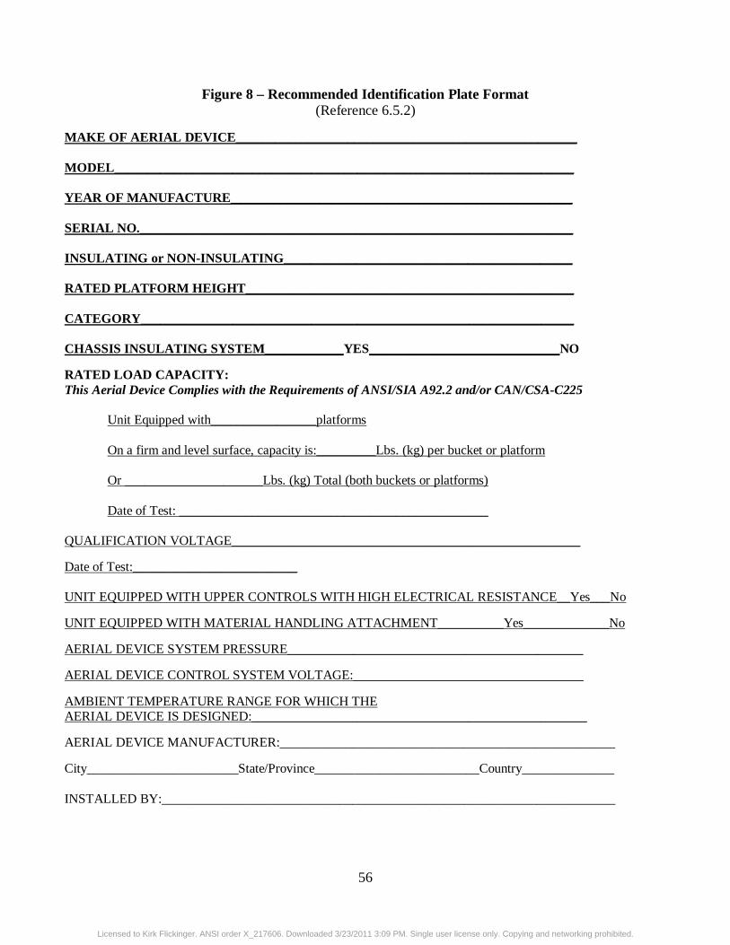
56
Figure 8 – Recommended Identification Plate Format (Reference 6.5.2)
MAKE OF AERIAL DEVICE____________________________________________________ MODEL______________________________________________________________________ YEAR OF MANUFACTURE____________________________________________________ SERIAL NO.__________________________________________________________________ INSULATING or NON-INSULATING____________________________________________ RATED PLATFORM HEIGHT__________________________________________________ CATEGORY__________________________________________________________________ CHASSIS INSULATING SYSTEM____________YES_____________________________NO
RATED LOAD CAPACITY: This Aerial Device Complies with the Requirements of ANSI/SIA A92.2 and/or CAN/CSA-C225
Unit Equipped with________________platforms
On a firm and level surface, capacity is:_________Lbs. (kg) per bucket or platform
Or _____________________Lbs. (kg) Total (both buckets or platforms)
Date of Test: _______________________________________________ QUALIFICATION VOLTAGE_____________________________________________________
Date of Test:_________________________ UNIT EQUIPPED WITH UPPER CONTROLS WITH HIGH ELECTRICAL RESISTANCE__Yes___No
UNIT EQUIPPED WITH MATERIAL HANDLING ATTACHMENT__________Yes_____________No
AERIAL DEVICE SYSTEM PRESSURE_____________________________________________
AERIAL DEVICE CONTROL SYSTEM VOLTAGE:___________________________________
AMBIENT TEMPERATURE RANGE FOR WHICH THE AERIAL DEVICE IS DESIGNED:___________________________________________________
AERIAL DEVICE MANUFACTURER:___________________________________________________
City_______________________State/Province_________________________Country______________ INSTALLED BY:_____________________________________________________________________
Licensed to Kirk Flickinger. ANSI order X_217606. Downloaded 3/23/2011 3:09 PM. Single user license only. Copying and networking prohibited.

57
The following Appendices (Appendix A-G) are furnished only to provide explanation, clarification, and potential guidance.
APPENDIX A – ELECTRICAL TEST TERMINOLOGY AND CLARIFI CATION 1) When an aerial device is to be used for ac application, Design tests shall be conducted with alternating current. These tests are conducted on the initial unit of a particular design. 2) Qualification tests are to be conducted per the appropriate section of Table 1, depending upon the rated voltage of intended use. 3) “Wet testing” is a description used for electrical testing after insulating components or insulating aerial devices have had water applied to them. This method is sometimes used in testing the resistivity and conductivity of insulating components, particularly the surface(s) of them. Properly maintained insulating components should not exhibit water absorption. The test values contained in this standard are for dry insulating components. 4) The leakage current recorded as part of the Qualification Test is to be provided as part of the test data, and can be used as a benchmark for future testing. 5) The term “certified test” is not used. The Qualification Test is the test that is certified as being accurate and applicable to a particular unit. APPENDIX B – DC APPLICATION When an aerial device is to be used for dc application as a Category A device, the following applies: Direct Current withstand Rated Line Voltage
Max* Boom Leakage Current
Time of Test
Double Rated Line Voltage
Over Voltage Test
“X” kV 0.5 microamperes /kV
3 minutes “2X”kV 2X(F) **kV
1) The double voltage and over voltage test are for 1 minute duration. 2) Record leakage current as data for future testing. * The leakage current should maintain a steady value for at least one minute before the test is concluded. ** F = Switching Factor or Over Voltage Factor.
Licensed to Kirk Flickinger. ANSI order X_217606. Downloaded 3/23/2011 3:09 PM. Single user license only. Copying and networking prohibited.

58
APPENDIX C – APPLICATION AND USES OF AERIAL DEVICES Category
Bare-Hand Gloving Live Line Tool* (e.g., Hot Stick)
Construction De-Energized
A B C Non-Insulating
X **
** X X
X X X X
X X X X
* Aerial Device is used as a work platform ** An aerial device manufactured as a Category A may be modified and used as a Category B and a Category B may be modified and used as a Category A in accordance with the manufacturer’s instructions. In the event that this is done, particular attention must be given to the appropriate qualification test, gradient control devices, conductive shields, conductive liners and bonding. Category B aerial devices can be rated higher than 46kV in order to facilitate changing them to Category A aerial devices for ‘bare-hand work’. Using Category B aerial devices on voltage levels above 46kV requires the use of live line tools with appropriate dielectric ratings. These tools are to be depended upon for primary protection, just as in all cases where the boom is used as secondary protection (Category B and C). APPENDIX D – ELECTRICAL TESTS FOR AERIAL DEVICES, IN SULATED PLATFORMS AND INSULATED LADDERS FOR AC APPLICATION Design
Qualification Periodic Field Periodic
Category A & B Category C Insulated Ladder and Platform
Table 1 Table 1 Table 1
Table 1 Table 1 Table 1
Table 2 Table 2 Table 2
Table 3 Table 3 Table 3
APPENDIX E – ELECTRICAL TESTS FOR AERIAL DEVICES BUI LT IN COMPLIANCE TO EARLIER EDITIONS OF THIS STANDARD. Previous A92.2 Standards allowed for dielectric ratings at 69kV and below* which do not meet this Edition. Previous testing requirements may be relied upon for those machines. However, use of the applicable tests herein provides confirmation of integrity. To assist users of these devices in application of periodic testing values of this standard, the following table is provided.
Licensed to Kirk Flickinger. ANSI order X_217606. Downloaded 3/23/2011 3:09 PM. Single user license only. Copying and networking prohibited.

59
Unit Rating
60 Hertz (rms) Test Direct Current Test
69 kV and Below
Voltage (kV)
Maximum Allowable Current (microamperes)
Time (Minutes)
Voltage (kV)
Maximum Allowable Current (microamperes)
Time (Minutes)
Measured Through Lower Electrode System
60 60 1 84 42 3
Measured without Lower Electrode System
60 600 1 84 84 3
* In an attempt to recognize that insulating aerial devices that are used for ‘gloving’ of electrical distribution voltages the rating of aerial devices were changed to ‘46kV and below’ in the 1990 Edition. The change in the rating was also meant to draw a clear distinction between machines rated for distribution voltages and those for the voltage levels of transmission lines. In the 1990 and later Editions, Category B aerial devices could be rated higher than 46kV in order to facilitate changing them to Category A aerial devices for ‘bare-hand work’. Using Category B aerial devices on voltage levels above 46kV requires the use of live line tools with appropriate dielectric ratings. These tools are to be depended upon for primary protection, just as in all cases where the boom is used as secondary protection (Categories B and C). APPENDIX F—PRECAUTIONS FOR USE OF AERIAL DEVICES ON OR NEAR ENERGIZED APPARATUS This appendix contains considerations for the determinations of Minimum Approach Distances to energized overhead power facilities for aerial devices and platform occupants and the differing levels of required skill and training corresponding to the differing levels of exposure to the associated hazards. Minimum Approach Distances are covered by various widely used industry standards and regulations. The most commonly known are OSHA Part 29 CFR 1900 and ANSI C2, the National Electrical Safety Code, which has been adopted by many State legislatures. In order to establish meaningful safe approach distances, both the insulation level of the aerial device and the qualification level(s) of the platform occupant(s) must be established. Definitions Insulating Aerial Device: An aerial device with dielectric components designed and tested to meet the specific electrical insulating rating consistent with the manufacturer’s identification plate. Non-insulating Aerial Device: An aerial device having no specific electrical rating. For purposes of determining Minimum Approach Distances, an insulating aerial device that is operating in an environment in which the voltages exceed those assigned to the device, is considered non-insulating. Unqualified Person: A person who does not have approval to approach energized lines and apparatus and has received no significant training regarding the electrical hazards involved in the placing of an aerial device, platform occupants and their tools closer to energized lines and facilities than the distances
Licensed to Kirk Flickinger. ANSI order X_217606. Downloaded 3/23/2011 3:09 PM. Single user license only. Copying and networking prohibited.

60
listed in Table A below. Qualified Person: A person who has received training, understands and is conversant in the electrical hazards involved in the placing of an aerial device, platform occupants and their tools closer to energized lines and facilities than the distances listed in Table A below, and has approval to perform the work. Note: This is an expansion to the “Qualified Person” definition in Section 3. It is designed to include the specialized knowledge required for determination of Minimum Approach Distances. To be qualified, different levels of training and skill are required depending upon the work to be accomplished and the electrical hazards associated with that work. Qualification levels range from the person unqualified to work on utility lines and associated facilities, but yet is subjected to significant risk of injury from electrical hazards in the performance of their work, to the level of a person that is qualified to work on, and in close proximity, to power utility lines and associated facilities. Qualified persons shall be trained and skilled to know the dangers involved and the methods to avoid them. Training shall be under the supervision of a person or persons qualified at that specific level or higher. It shall be clear that the term “qualified” represents different levels of training and skill. An example of work requiring a lesser amount of training is an aerial device operator and/or platform occupant performing maintenance on a building without any work objective relative to the energized conductors attached to the building. Training, however, is required for this aerial device operator and platform occupant(s) to know how to address those conductors. Note: Person(s) with the above lesser amount of training (and the aerial device and tools) can approach closer than the distances listed in applicable standards provided the energized conductors and associated facilities are guarded or covered with appropriate protective equipment. Such protective equipment shall be installed only by person(s) who has been qualified to do so. An example of work requiring a high level of training and skill is the person qualified to work on, and in close proximity, to power utility lines and associated facilities. Minimum Approach Distances for utility linemen are published and reviewed continually by the National Electrical Safety Code committees. They are found in the most recent edition of the Code in Part 4, Rules for Employees and in Part 29 CFR 1910.269, but they can be increased by the State or administrative authority having jurisdiction. Training of Qualified Person(s) is the responsibility of the employer or his designated contractor(s) and can be classroom, hands-on or a combination, as deemed appropriate by the employer for the degree of risk involved. An unqualified person, as an operator, shall not approach energized conductors or facilities that will place the insulating or non-insulating aerial device, the operator and other platform occupants, and their tools, closer to such facilities that the distances shown in Table A. A qualified communications person, as an operator, shall not approach energized conductors or facilities that will place the insulating or non-insulating aerial device, the operator and other platform occupants, and their tools, closer to such facilities than the distances set forth in Part 29 CFR 1910.268 and the National Electrical Safety Code.
Licensed to Kirk Flickinger. ANSI order X_217606. Downloaded 3/23/2011 3:09 PM. Single user license only. Copying and networking prohibited.

61
A qualified line clearance tree trimmer, as an operator, shall not approach energized conductors or facilities that will place the insulating or non-insulating aerial device, the operator and other occupants, and their tools, closer to such facilities than the distances set forth in Parts 29 CFR 1910.268, 1910.269, or ANSI/ISA Z133.1. A qualified lineman, as an operator, shall not approach energized conductors or facilities that will place the insulating or non-insulating aerial device, the operator and other platform occupants, and their tools, closer to such facilities than the distances set forth in Part 29 CFR 1910.269 and the National Electrical Safety Code. Higher levels of qualifications are required for electrical linemen to physically contact energized conductors and facilities from Category A, B, and C aerial devices. Table A Voltage
Minimum Approach Distance
Up to 50 kV Above 50 kV
10 feet 10 feet plus 4 inches for every 10 kV over 50 kV
Exception: For an aerial device in transit with the lift stowed, the clearance can be reduced to 4 feet for voltages of up to 50 kV. If the voltage is higher than 50 kV, the clearance shall be increased 4 inches for every 10 kV over that voltage. Ref: OSHA Part 29 CFR 1910.333(c)(3)(iii)(A)(1) The following standards contain tables and information that govern Minimum Approach Distances to energized overhead power facilities for users and operators of aerial devices: Part 29 CFR 1910.333 Selection and use of work practices Part 29 CFR 1910.268 Telecommunications Part 29 CFR 1910.269 Electric Power Generation, Transmissions and Distribution Part 29 CFR 1926.950 Power Transmission and Distribution ANSI/IEEE C2 National Electrical Safety Code, Part 4, Rules for the Operation of Electric Supply and Communications Lines and Equipment ANSI/ISA Z133.1 Tree Care Operations – Safety Requirements It is imperative that users and operators of aerial devices be familiar with the standard(s) pertinent to the type of work being performed. Handling Energized Apparatus When the boom tip jib and/or winch of a category B or C aerial device is used for handling energized conductors and apparatus, the energized conductors and apparatus shall be insulated from the boom tip with electrical protection devices that are rated, tested and maintained for the appropriate rated line voltage. Boom tip jibs used in material handling on aerial devices shall be considered non-insulating unless the jib has been rated, tested and maintained for the appropriate line voltage. Safety rules and work practices may vary significantly for different users, but one universal rule that applies is when jibs are used as a live-line tool with category B and C aerial devices, platform occupants(s) must use protective equipment such as gloves and cover-ups. If the winch line is used to lift energized apparatus, the energized apparatus shall be insulated from the jib tip with electrical protection devices that are rated, tested, and maintained for the appropriate line voltage. The winch line shall not be considered as
Licensed to Kirk Flickinger. ANSI order X_217606. Downloaded 3/23/2011 3:09 PM. Single user license only. Copying and networking prohibited.

62
insulating. For multi-phase lifting with conductor holders and a cross-arm, phase to phase protection shall be accomplished with a cross-arm that is rated, tested and maintained for appropriate line voltage. Live-line tools and jibs shall be used in agreement with manufacturer’s recommendations. Hooks used to lift loads must have a safety latch. A visual inspection must be performed periodically on all tools, winch lines, hooks and jibs used in live-line working to ensure structural integrity. Minimum Approach Distances shall be maintained by the electrical worker to assure clearances between objects at different electrical potential when performing live-line work. This applies to the worker’s reach including any non-insulating object above the insulated section of the aerial device. The Minimum Approach Distance may be obtained from sources such as but not limited to.: ANSI C-2 National Electrical Safety Code ANSI C-1 National Electrical Code Part 29 CFR 1926.950 Part 29 CFR 1910.269 Work practices Protective Equipment This subject varies widely depending upon employer safety rules; hence its use should be governed by company work rules and safety practices (example glove and cover-up). Such practices are predicated upon OHSA, ANSI C2 and recognized industry practice, such as but not limited to: Part 29 CFR 1910.335 Safeguards for Personnel Protection IEEE Std. 516-1995 Guide for Maintenance Methods on Energized Power lines Insulating Liners and Insulating Baskets A dielectrically tested insulating liner or insulating basket is intended to prevent electrical current flow through the lower extremities of the basket occupant. This is one element in a system approach that includes both work practices and materials designed to avoid electrical contact. Such a liner or basket shall not be considered primary insulation. Ground Persons An aerial device in close proximity (or contact) with an energized conductor can result in current flow that energizes the vehicle. Such an occurrence results in a potentially hazardous condition for all ground personnel who can contact the vehicle or any conductive object attached to it, such as a trailer. In some instances, ground gradients (step potentials) can be elevated to a dangerous level for those near, but not necessarily contacting, the vehicle or its attachments. Rules covering protection of ground persons can be obtained from sources such as but not limited to: Part 29 CFR 1910.333 ANSI C-2 National Electrical Safety Code ANSI C-1 National Electrical Code Part 29 CFR 1926.950 Part 29 CFR 1910.269 Work Practices
Licensed to Kirk Flickinger. ANSI order X_217606. Downloaded 3/23/2011 3:09 PM. Single user license only. Copying and networking prohibited.

63
APPENDIX G – RECOMMENDED IDENTIFICATION AND INSTRUCT ION SYMBOLS FOR CONTROL FUNCTIONS
The manufacturers of aerial devices complying with this standard have provided the following symbols and wording as suggested identification and instructional guides for aerial device controls.
Licensed to Kirk Flickinger. ANSI order X_217606. Downloaded 3/23/2011 3:09 PM. Single user license only. Copying and networking prohibited.

64
American National Standards for Aerial Work Platforms ANSI/SIA A92.2 Vehicle-Mounted Elevating and Rotating Aerial Devices ANSI/SIA A92.3 Manually Propelled Elevating Aerial Platforms ANSI/SIA A92.5 Boom-Supported Elevating Work Platforms ANSI/SIA A92.6 Self -Propelled Elevating Work Platforms ANSI/SIA A92.7 Airline Ground Support Vehicle-Mounted Vertical Lift Devices ANSI/SIA A92.8 Vehicle-Mounted Bridge Inspection and Maintenance Devices ANSI/SIA A92.9 Mast-Climbing Work Platforms ANSI/SIA A92.10 Transport Platforms ANSI/SIA A92 Standards are under continual development. Contact the Scaffold Industry Association for the current updated information. Scaffold Industry Association, Inc. 'The Voice of the Scaffold and Access Industry' 400 Admiral Boulevard Kansas City, MO 64106 Phone: 816-595-4860 Fax: 816-472-7765 Email: [email protected] Web: www.scaffold.org
Licensed to Kirk Flickinger. ANSI order X_217606. Downloaded 3/23/2011 3:09 PM. Single user license only. Copying and networking prohibited.