for use with two-component sealant and adhesive materials
TRANSCRIPT

3A6165MEN
Instructions - Parts
EFRElectric Fixed-Ratio Proportioner
For use with two-component sealant and adhesive materials. For professional use only.
Not approved for use in explosive atmospheres or hazardous locations.
2000 psi (13.8 MPa, 138 bar) Maximum Fluid Inlet Pressure3500 psi (24.1 MPa, 241 bar) Maximum Fluid Outlet Pressure
See page 3 for model information.
Important Safety InstructionsRead all warnings and instructions in this manual and in related manuals before using the equipment. Save these instruc-tions.

2 3A6165M
ContentsRelated Manuals . . . . . . . . . . . . . . . . . . . . . . . . . . . . . . 2Models . . . . . . . . . . . . . . . . . . . . . . . . . . . . . . . . . . . . . . 3Warnings . . . . . . . . . . . . . . . . . . . . . . . . . . . . . . . . . . . . 4
Keep Components A (Red) and B (Blue) Separate . . . . . . . . . . . . . . . . . . . . . . . . . . . . . . . . . . . . . . . . . 7Changing Materials . . . . . . . . . . . . . . . . . . . . . . . . . 7A (Red) and B (Blue) Components . . . . . . . . . . . . . 7
Component Identification . . . . . . . . . . . . . . . . . . . . . . 8Typical Installation . . . . . . . . . . . . . . . . . . . . . . . . . . 9Advanced Display Module (ADM) . . . . . . . . . . . . . 11
Installation . . . . . . . . . . . . . . . . . . . . . . . . . . . . . . . . . . 13Grounding . . . . . . . . . . . . . . . . . . . . . . . . . . . . . . . 13Power Requirements . . . . . . . . . . . . . . . . . . . . . . . 13Connect Power . . . . . . . . . . . . . . . . . . . . . . . . . . . 13Install Vented Oil Cap Before Using Equipment . . 15
Setup . . . . . . . . . . . . . . . . . . . . . . . . . . . . . . . . . . . . . . 16Flushing . . . . . . . . . . . . . . . . . . . . . . . . . . . . . . . . . 17Driver and Yoke Position . . . . . . . . . . . . . . . . . . . . 18Fluid Pathway . . . . . . . . . . . . . . . . . . . . . . . . . . . . 20CAN Cable Connections (With Day Tanks) . . . . . . 21Signal Connections . . . . . . . . . . . . . . . . . . . . . . . . 22
Operation . . . . . . . . . . . . . . . . . . . . . . . . . . . . . . . . . . . 26Startup . . . . . . . . . . . . . . . . . . . . . . . . . . . . . . . . . . 26Shutdown . . . . . . . . . . . . . . . . . . . . . . . . . . . . . . . . 27Pressure Relief Procedure . . . . . . . . . . . . . . . . . . . 27Adjust Material Inlet Pressure . . . . . . . . . . . . . . . . 28
Maintenance . . . . . . . . . . . . . . . . . . . . . . . . . . . . . . . . 29Preventative Maintenance Schedule . . . . . . . . . . . 29Check Oil Level . . . . . . . . . . . . . . . . . . . . . . . . . . . 29Change the Oil . . . . . . . . . . . . . . . . . . . . . . . . . . . . 30Bearing Pre-Load . . . . . . . . . . . . . . . . . . . . . . . . . . 30Calibrate the Electric Driver . . . . . . . . . . . . . . . . . . 30ADM - Battery Replacement and Screen Cleaning . . . . . . . . . . . . . . . . . . . . . . . . . . . . . . . . . . . . . . . . 31
Troubleshooting . . . . . . . . . . . . . . . . . . . . . . . . . . . . . 32EFR Error Codes . . . . . . . . . . . . . . . . . . . . . . . . . . 34
Parts . . . . . . . . . . . . . . . . . . . . . . . . . . . . . . . . . . . . . . . 43EFR Common System Parts . . . . . . . . . . . . . . . . . 43Fluid Section . . . . . . . . . . . . . . . . . . . . . . . . . . . . . 44Driver and Yoke Assembly . . . . . . . . . . . . . . . . . . . 45Electrical Assembly . . . . . . . . . . . . . . . . . . . . . . . . 47
Accessories . . . . . . . . . . . . . . . . . . . . . . . . . . . . . . . . . 48Voltex Dynamic Mix Valve . . . . . . . . . . . . . . . . . . . 48Applicator . . . . . . . . . . . . . . . . . . . . . . . . . . . . . . . . 48Dispense Valve Interface Kit . . . . . . . . . . . . . . . . . 48Inlet Regulator Kits . . . . . . . . . . . . . . . . . . . . . . . . . 48Additional Accessories . . . . . . . . . . . . . . . . . . . . . . 48EFR Supply System Accessories . . . . . . . . . . . . . 49
Advanced Display Module (ADM) Operation . . . . . . 55
ADM Screen Overview . . . . . . . . . . . . . . . . . . . . . . . . 56Home Screen . . . . . . . . . . . . . . . . . . . . . . . . . . . . 56Voltex Dynamic Mix Valve Run Screen . . . . . . . . . 58Index Menu . . . . . . . . . . . . . . . . . . . . . . . . . . . . . . 60
Software Update . . . . . . . . . . . . . . . . . . . . . . . . . . . . . 7117Y711 Software Update Procedure . . . . . . . . . . . 71
I/O Integration . . . . . . . . . . . . . . . . . . . . . . . . . . . . . . . 72I/O Integration Cable Colors . . . . . . . . . . . . . . . . . 73I/O Integration Diagrams . . . . . . . . . . . . . . . . . . . . 74Remote Sequence Selection . . . . . . . . . . . . . . . . . 77Foot Switch Connection . . . . . . . . . . . . . . . . . . . . 77
Wiring Diagrams . . . . . . . . . . . . . . . . . . . . . . . . . . . . . 78Power Wiring . . . . . . . . . . . . . . . . . . . . . . . . . . . . . 78
Dimensions . . . . . . . . . . . . . . . . . . . . . . . . . . . . . . . . . 79Technical Specifications . . . . . . . . . . . . . . . . . . . . . . 80California Proposition 65 . . . . . . . . . . . . . . . . . . . . . . 81Graco Standard Warranty . . . . . . . . . . . . . . . . . . . . . 82Graco Information . . . . . . . . . . . . . . . . . . . . . . . . . . . 82
Related ManualsManual Description
3A0019 Z-Series Chemical Pumps Instruc-tions-Parts
3A6482 APD20 Advanced Precision Driver Instructions
312185 MD2 Valve Instructions-Parts
3A6338 Communications Gateway Module Instal-lation Kit Instructions-Parts
3A6394 Z-Series Chemical Pumps High Wear Instructions-Parts
3A6321 ADM Token In-System Programming Instructions
3A8115 Voltex Dynamic Mix Valve Instruc-tions-Parts
3A0395 Stainless Steel Tank Stands Instructions-Parts
3A1299 Carbon Steel Tank Stands Instructions-Parts

Models
3A6165M 3
ModelsUse the following matrix to determine the 8-digit system part number.
NOTE: To order replacement parts, see the Parts section on page 43. The digits in the matrix do not correspond to the Ref. Nos. in the Parts drawings and lists.
* An EFR may be configured without pumps by designating “X” for both pump selections. Inlet/Outlet Fitting selec-tion is required to specify the fittings shipped with the system. Pumps can be purchased and assembled sepa-rately before placing the system into service. See the Z-Series Chemical Pumps Instructions-Parts manual.
+ EFR configurations with High-Wear pumps are only available with stainless steel Inlet/Outlet Fitting options, and cannot be selected in combination with standard EFR pumps.
EFR(First, Second
and Third Digits)Digit 4 Digit 5 Digit 6 Digit 7 Digit 8
System Designator Voltage Options Control Options A Side Pump B Side Pump Inlet/Outlet Fitting
OptionsEFR
(Electric Fixed-Ratio Pro-
portioner)
2 240V A ADM A 5 cc A 5 cc C Carbon and Stainless Steel
4 480V B 10 cc B 10 cc S Stainless SteelC 15 cc C 15 cc X Not ProvidedD 20 cc D 20 ccE 25 cc E 25 ccF 30 cc F 30 ccG 35 cc G 35 ccH 40 cc H 40 ccI 45 cc I 45 ccJ 50 cc J 50 ccK 60 cc K 60 ccL 65 cc L 65 ccM 70 cc M 70 ccN 75 cc N 75 ccO 80 cc O 80 ccP 86 cc P 86 ccQ 90 cc Q 90 ccR 100 cc R 100 ccS 105 cc S 105 ccT 120 cc T 120 ccU 140 cc U 140 ccV 150 cc V 150 ccW 160 cc W 160 ccX* No Pump X* No Pump
1 10 cc High Wear 1 10 cc High Wear
1B 20 cc Elite 1B 20 cc Elite1C 40 cc Elite 1C 40 cc Elite1D 80 cc Elite 1D 80 cc Elite1E 100 cc Elite 1E 100 cc Elite1F 120 cc Elite 1F 120 cc Elite1G 160 cc Elite 1G 160 cc Elite

Warnings
4 3A6165M
WarningsThe following warnings are for the setup, use, grounding, maintenance, and repair of this equipment. The exclama-tion point symbol alerts you to a general warning and the hazard symbols refer to procedure-specific risks. When these symbols appear in the body of this manual or on warning labels, refer back to these Warnings. Product-specific hazard symbols and warnings not covered in this section may appear throughout the body of this manual where applicable.
DANGERSEVERE ELECTRIC SHOCK HAZARDThis equipment can be powered by more than 240 V. Contact with this voltage will cause death or serious injury.• Turn off and disconnect power at main switch before disconnecting any cables and before servicing
equipment.• This equipment must be grounded. Connect only to grounded power source.• All electrical wiring must be done by a qualified electrician and comply with all local codes and
regulations.

Warnings
3A6165M 5
WARNINGSKIN INJECTION HAZARDHigh-pressure fluid from dispensing device, hose leaks, or ruptured components will pierce skin. This may look like just a cut, but it is a serious injury that can result in amputation. Get immediate surgical treatment.• Do not point dispensing device at anyone or at any part of the body.• Do not put your hand over the fluid outlet.• Do not stop or deflect leaks with your hand, body, glove, or rag.• Follow the Pressure Relief Procedure when you stop dispensing and before cleaning, checking, or
servicing equipment.• Tighten all fluid connections before operating the equipment.• Check hoses and couplings daily. Replace worn or damaged parts immediately.
FIRE AND EXPLOSION HAZARDFlammable fumes, such as solvent and paint fumes, in work area can ignite or explode. Paint or solvent flowing through the equipment can cause static sparking. To help prevent fire and explosion:• Use equipment only in well-ventilated area.• Eliminate all ignition sources; such as pilot lights, cigarettes, portable electric lamps, and plastic drop
cloths (potential static sparking). • Ground all equipment in the work area. See Grounding instructions.• Never spray or flush solvent at high pressure.• Keep work area free of debris, including solvent, rags and gasoline.• Do not plug or unplug power cords, or turn power or light switches on or off when flammable fumes
are present.• Use only grounded hoses.• Stop operation immediately if static sparking occurs or you feel a shock. Do not use equipment until
you identify and correct the problem.• Keep a working fire extinguisher in the work area.
TOXIC FLUID OR FUMES HAZARDToxic fluids or fumes can cause serious injury or death if splashed in the eyes or on skin, inhaled, or swallowed.• Read Safety Data Sheets (SDSs) to know the specific hazards of the fluids you are using.• Store hazardous fluid in approved containers, and dispose of it according to applicable guidelines.

Warnings
6 3A6165M
MOVING PARTS HAZARDMoving parts can pinch, cut or amputate fingers and other body parts.• Keep clear of moving parts.• Do not operate equipment with protective guards or covers removed.• Equipment can start without warning. Before checking, moving, or servicing equipment, follow the
Pressure Relief Procedure and disconnect all power sources.
EQUIPMENT MISUSE HAZARDMisuse can cause death or serious injury.• Do not operate the unit when fatigued or under the influence of drugs or alcohol.• Do not exceed the maximum working pressure or temperature rating of the lowest rated system
component. See Technical Specifications in all equipment manuals.• Use fluids and solvents that are compatible with equipment wetted parts. See Technical
Specifications in all equipment manuals. Read fluid and solvent manufacturer’s warnings. For complete information about your material, request Safety Data Sheets (SDSs) from distributor or retailer.
• Turn off all equipment and follow the Pressure Relief Procedure when equipment is not in use.• Check equipment daily. Repair or replace worn or damaged parts immediately with genuine
manufacturer’s replacement parts only.• Do not alter or modify equipment. Alterations or modifications may void agency approvals and create
safety hazards.• Make sure all equipment is rated and approved for the environment in which you are using it.• Use equipment only for its intended purpose. Call your distributor for information.• Route hoses and cables away from traffic areas, sharp edges, moving parts, and hot surfaces.• Do not kink or over bend hoses or use hoses to pull equipment.• Keep children and animals away from work area.• Comply with all applicable safety regulations.
PERSONAL PROTECTIVE EQUIPMENTWear appropriate protective equipment when in the work area to help prevent serious injury, including eye injury, hearing loss, inhalation of toxic fumes, and burns. Protective equipment includes but is not limited to:• Protective eyewear, and hearing protection.• Respirators, protective clothing, and gloves as recommended by the fluid and solvent manufacturer.
WARNING

Warnings
3A6165M 7
Keep Components A (Red) and B (Blue) Separate
Changing Materials
A (Red) and B (Blue) ComponentsNOTE: Material suppliers can vary in how they refer to plural component materials.
For all machines:
• The A (Red) side is intended for hardeners and catalysts.
• The B (Blue) side is intended for polyols, resins, and bases. Regardless of the configuration of material used, the high volume material must be in the B (Blue) side.
Cross-contamination can result in cured material in fluid lines which could cause serious injury or damage equipment. To prevent cross-contamination:
• Never interchange component A (red) and component B (Blue) wetted parts.
• Never use solvent on one side if it has been contaminated from the other side.
NOTICE
Changing the material types used in your equipment requires special attention to avoid equipment damage and downtime.
• When changing materials, flush the equipment multiple times to ensure it is thoroughly clean.
• Check with your material manufacturer for chemical compatibility.

Component Identification
8 3A6165M
Component Identification
Key:A A PumpB B PumpC Power Disconnect SwitchD Advanced Display Module (ADM)F Pump Yoke ShroudG Electric DriverH Incoming Power ConnectionJ Pump InletsK Pump OutletsM Driver Communication and I/O Connectors
N Lift RingP Pressure Relief Drain TubesR A-Side Outlet Drain/Relief Valve*S B-Side Outlet Drain/Relief Valve*
* Required components supplied with the system. EFR systems configured without pumps are provided with drain/relief valves, which must be installed after the pumps are assembled, but before placing the system into service.
FIG. 1: Component Identification
F
GH
C
M
A
S
B
D
K
J
N
PR

Component Identification
3A6165M 9
Typical Installation
* Required accessories not supplied with the proportioner.
✖ Optional accessories not supplied with the proportioner.
FIG. 2: Typical Installation with Supply Systems
Dispense Valve*
A Supply System*
B Supply System*
Power Cord with UserSupplied Dedicated Circuit ProtectionInlet Regulators ✖
EFR Proportioner

Component Identification
10 3A6165M
* Required accessories not supplied with the proportioner.
✖ Optional accessories not supplied with the proportioner.
FIG. 3: Typical Installation with Day Tanks
Dispense Valve*
A Day Tank* B Day Tank*
Power Cord with UserSupplied Dedicated Circuit Protection
Inlet Regulators ✖
EFR Proportioner
Component Identification
3A6165M 11
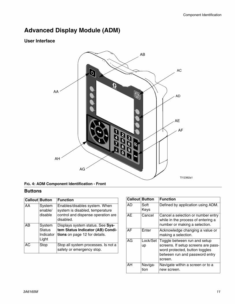
Advanced Display Module (ADM)User Interface
Buttons
FIG. 4: ADM Component Identification - Front
TI12362a1
AA
AB
AC
AE
AH
AG
AF
AD
Callout Button FunctionAA System
enable/ disable
Enables/disables system. When system is disabled, temperature control and dispense operation are disabled.
AB System Status Indicator Light
Displays system status. See Sys-tem Status Indicator (AB) Condi-tions on page 12 for details.
AC Stop Stop all system processes. Is not a safety or emergency stop.
AD Soft Keys
Defined by application using ADM.
AE Cancel Cancel a selection or number entry while in the process of entering a number or making a selection.
AF Enter Acknowledge changing a value or making a selection.
AG Lock/Setup
Toggle between run and setup screens. If setup screens are pass-word protected, button toggles between run and password entry screen.
AH Naviga-tion
Navigate within a screen or to a new screen.
Callout Button Function
Component Identification
12 3A6165M
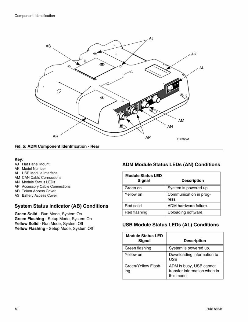
Key:AJ Flat Panel MountAK Model NumberAL USB Module InterfaceAM CAN Cable ConnectionsAN Module Status LEDsAP Accessory Cable ConnectionsAR Token Access CoverAS Battery Access Cover
System Status Indicator (AB) ConditionsGreen Solid - Run Mode, System OnGreen Flashing - Setup Mode, System OnYellow Solid - Run Mode, System OffYellow Flashing - Setup Mode, System Off
ADM Module Status LEDs (AN) Conditions
USB Module Status LEDs (AL) Conditions
FIG. 5: ADM Component Identification - Rear
AR
AK
AJ
AL
AP
ANAM
AS
ti12363a1
Module Status LED Signal Description
Green on System is powered up.
Yellow on Communication in prog-ress.
Red solid ADM hardware failure.
Red flashing Uploading software.
Module Status LED Signal Description
Green flashing System is powered up.
Yellow on Downloading information to USB
Green/Yellow Flash-ing
ADM is busy, USB cannot transfer information when in this mode

Installation
3A6165M 13
Installation
Grounding
EFR: grounded through the power cord (customer sup-plied).
Fluid supply containers: follow local code.
Object being dispensed: follow local code.
Solvent pails used when flushing: follow local code. Use only conductive metal pails, placed on a grounded surface. Do not place the pail on a nonconductive surface, such as paper or cardboard, which interrupts grounding continuity.
To maintain grounding continuity when flushing or relieving pressure: hold metal part of the dispense valve firmly to the side of a grounded metal pail, then trigger the dispense valve.
Power RequirementsThe system requires a dedicated circuit protected with a circuit breaker.
Connect Power1. Cut power cord wires to the following lengths:
• Ground wire - 6.5 inches (16.5 cm)• Power wires - 3.0 inches (7.6 cm)• Add ferrules as necessary. See FIG. 6.
2. Remove the four screws to separate the junction box cover (BA) and disconnect switch (C) from the junction box (BB) on the electrical driver.
All electrical wiring must be done by a qualified elec-trician and comply with all local codes and regula-tions.
The equipment must be grounded to reduce the risk of static sparking and electric shock. Electric or static sparking can cause fumes to ignite or explode. Improper grounding can cause electric shock. Grounding provides an escape wire for the electric current.
Voltage Phase Hz Current200-240 VAC 1 50/60 20 A400-480 VAC 1 50/60 10 A
FIG. 6: Power Cord
FIG. 7: Remove Junction Box Cover
BB
BA
C
Installation
14 3A6165M
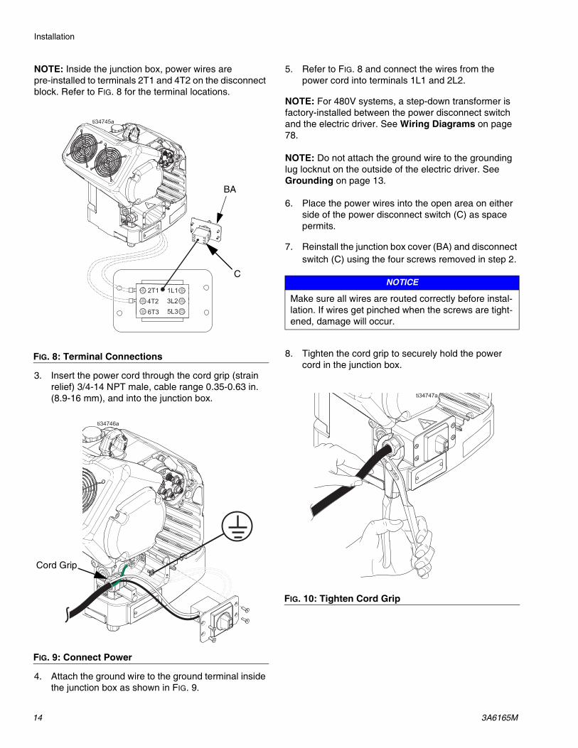
NOTE: Inside the junction box, power wires are pre-installed to terminals 2T1 and 4T2 on the disconnect block. Refer to FIG. 8 for the terminal locations.
3. Insert the power cord through the cord grip (strain relief) 3/4-14 NPT male, cable range 0.35-0.63 in. (8.9-16 mm), and into the junction box.
4. Attach the ground wire to the ground terminal inside the junction box as shown in FIG. 9.
5. Refer to FIG. 8 and connect the wires from the power cord into terminals 1L1 and 2L2.
NOTE: For 480V systems, a step-down transformer is factory-installed between the power disconnect switch and the electric driver. See Wiring Diagrams on page 78.
NOTE: Do not attach the ground wire to the grounding lug locknut on the outside of the electric driver. See Grounding on page 13.
6. Place the power wires into the open area on either side of the power disconnect switch (C) as space permits.
7. Reinstall the junction box cover (BA) and disconnect switch (C) using the four screws removed in step 2.
8. Tighten the cord grip to securely hold the power cord in the junction box.
FIG. 8: Terminal Connections
FIG. 9: Connect Power
BA
C
Cord Grip
NOTICE
Make sure all wires are routed correctly before instal-lation. If wires get pinched when the screws are tight-ened, damage will occur.
FIG. 10: Tighten Cord Grip

Installation
3A6165M 15
Install Vented Oil Cap Before Using EquipmentThe driver gear-box is shipped from the factory pre-filled with oil. The temporary unvented cap (PX) prevents oil leaks during shipment. This temporary cap must be replaced with the vented oil cap (PY), supplied with the equipment, before use.
NOTE: Prior to use, check oil level. Oil level should be half way up the sight glass.
FIG. 11: Unvented and Vented Oil Caps
PX
PY

Setup
16 3A6165M
SetupAfter placing the EFR in the desired area of operation:
NOTE: Make sure the EFR is placed on a level surface. See Dimensions on page 79 for space requirements.
1. Anchor the EFR to a fixed mounting location. See Dimensions on page 79.
2. Follow steps a through d to install pumps ordered separately for EFR systems configured without pumps. If the EFR is already configured with pumps, proceed to step 3.
a. Adjust the electric driver position to the correct ratio of the pumps selected. See Check Driver and Yoke Position and Change Driver and Yoke Position on page 19.
b. Install inlet fittings (provided with the EFR) onto the A and B pumps purchased separately. See Parts on page 43.
c. Install the pumps onto the EFR. See Parts on page 43. The B pump (larger volume) should be located on the side of the driver electrical con-nections. Use spring clamps (106) (provided with pumps) to couple the pump to yoke adapt-ers (216).
d. Install adapters (107) into the pump outlets, then install outlet manifold assemblies (108, 109) and drain tubes (112).
3. If applicable, assemble and connect the fluid inlet regulators to the EFR fluid inlets (J). See Inlet Reg-ulator Kits on page 48.
4. Connect the supply systems.
a. Install feed pumps for component A (Red) and B (Blue) supply drums. See FIG. 2, page 9.
b. Ensure the supply systems and, if applicable, the inlet regulators are off or set to zero pres-sure before connecting.
NOTE: Supply hoses from feed pumps should be 3/4 in. (19 mm) ID minimum.
c. Assemble, connect and tighten the component B (Blue) inlet hose to the B-pump inlet (J).
d. Assemble, connect and tighten the component A (Red) inlet hose to the A-pump inlet (J).
inlet pressuregauge
2000 psi max inlet pressure
J

Setup
3A6165M 17
5. Attach the fluid outlet hoses to the pump outlets (K). Adapter fittings may be required, see Additional Accessories on page 48.
6. Connect the outlet hoses to the dispense valve. Refer to your dispense valve component manual for com-plete installation instructions.
7. Pressure check the hoses. If there are no leaks, secure the outlet hoses together to protect them from damage.
Flushing
• Flush out old fluid with new fluid, or flush out old fluid with a compatible solvent before introducing new fluid.
• Use the lowest possible pressure when flushing.
• All fluid components are compatible with common sol-vents.
• To flush the entire system, circulate through the dis-pense valve and drain valve.
KTo avoid fire and explosion, always ground equipment and waste container. To avoid static sparking and injury from splashing, always flush at the lowest pos-sible pressure.

Setup
18 3A6165M
Driver and Yoke Position
The driver and yoke position must be set for the volume mix ratio of the system.
NOTE: The mix ratio is only determined by the size of the two pumps installed. Changing the driver and yoke position does not directly change the mix ratio, but it is required to balance the pressure between the two pumps.
Check Driver and Yoke Position1. Turn the power disconnect switch (C) to the OFF
position.
2. Perform the Pressure Relief Procedure on page 27.
3. Loosen the four screws and remove the pump yoke shroud (F).
4. Verify the correct pumps are mounted for your mix ratio by volume. Divide the displacement of the B-side pump by the displacement of the A-side pump (B/A) to calculate the volume ratio.
5. Verify the driver position is adjusted correctly for that mix ratio. If not, perform the following Change Driver and Yoke Position procedure.
NOTE: There are numbered indicator lines on the driver mounting plate and on the pump yoke that show the ratio adjustment.
F
Screws
IndicatorLines
Setup
3A6165M 19
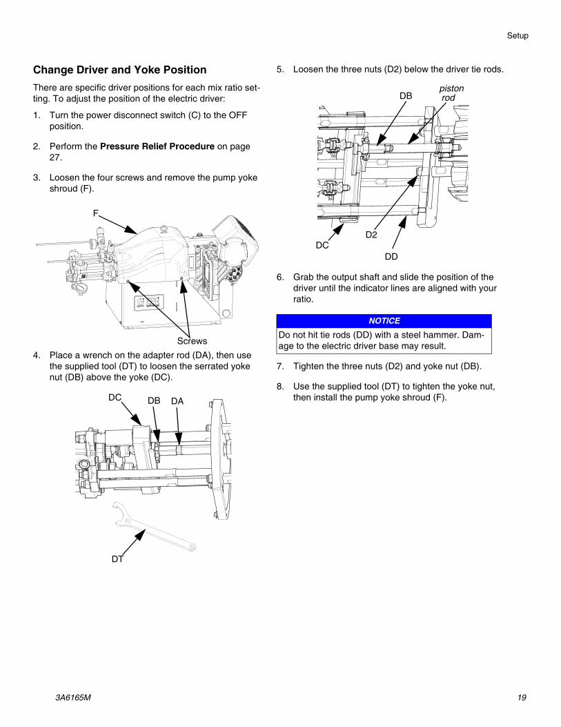
Change Driver and Yoke PositionThere are specific driver positions for each mix ratio set-ting. To adjust the position of the electric driver:
1. Turn the power disconnect switch (C) to the OFF position.
2. Perform the Pressure Relief Procedure on page 27.
3. Loosen the four screws and remove the pump yoke shroud (F).
4. Place a wrench on the adapter rod (DA), then use the supplied tool (DT) to loosen the serrated yoke nut (DB) above the yoke (DC).
5. Loosen the three nuts (D2) below the driver tie rods.
6. Grab the output shaft and slide the position of the driver until the indicator lines are aligned with your ratio.
7. Tighten the three nuts (D2) and yoke nut (DB).
8. Use the supplied tool (DT) to tighten the yoke nut, then install the pump yoke shroud (F).
F
Screws
DADBDC
DT
NOTICE
Do not hit tie rods (DD) with a steel hammer. Dam-age to the electric driver base may result.
pistonrodDB
DCD2
DD
Setup
20 3A6165M
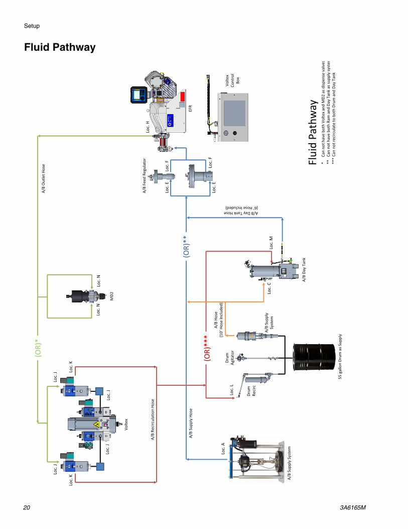
Fluid Pathway
����
����
��
��
�
����
��
����
����
�����
�
����
���
����
����
����
�
�� �
����
� ���
�
����
�����
���
����
����
��
��
����
���
����
����
� �
��!
!"
��������������� �#����� � ���! !"
����
$ !
�� �
���
��
����
%��
�����
����
� ���
���
�����
���
&��
'
(�)
*$�
&��
'+�
����
��
'
,��-
��
,��-
�+
,��-
�*
,��-
�*,�
�-�$
,��-
�$
,��-
��
,��-
�.,�
�-�.
,��-
�/,�
�-�/
,��-
�0,�
�-�0
,��-
�,
,��-
�(
,��-
�/,�
�-�/
$��
!�1�
�23
�
�%�"
4
�%�"
44
�%�"
444
4����
�+��
����
�2�5
�6�
�2�&
��
'���!
�(�)
����!
��� �
� �5�
5 �
44���
+���
����2
�5 �
6��2
����
���!
���
����
����
�����
��
�� �
444�
+���
�����
����
���
���
�6��
2���
����
�!��
���
���

Setup
3A6165M 21
CAN Cable Connections (With Day Tanks)
A Da
y Ta
nk
EFR
Volte
x Con
trol
Box
B Da
y Ta
nk
Port
1 o
r 2 12
2487
124003
124003
Supplied with
Voltex System

Setup
22 3A6165M
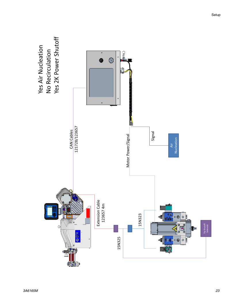
Signal ConnectionsN
o Ai
r Nuc
leat
ion
No
Reci
rcul
atio
n N
o 2K
Pow
er S
huto
ff
CAN
Cab
les
1217
28/1
2365
7
15N
323
Mot
or P
ower
/Sig
nal
Exte
nsio
n Ca
ble
1236
57 4
m
Setup
3A6165M 23
Yes A
ir N
ucle
atio
n N
o Re
circ
ulat
ion
Yes 2
K Po
wer
Shu
toff
Mot
or P
ower
/Sig
nal
Air
Nuc
leat
ion Sign
al
Exte
nsio
n Ca
ble
1236
57 4
m
Tip
Shut
off
Sole
noid
CAN
Cab
les
1217
28/1
2365
7
15N
325
15N
323

Setup
24 3A6165M
No
Air N
ucle
atio
n Ye
s Rec
ircul
atio
n N
o 2K
Pow
er S
huto
ff
15N
324
Mot
or P
ower
/Sig
nal
Exte
nsio
n Ca
ble
1236
57 4
m
CAN
Cab
les
1217
28/1
2365
7
Setup
3A6165M 25
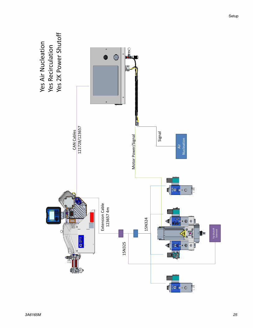
Yes A
ir N
ucle
atio
n Ye
s Rec
ircul
atio
n Ye
s 2K
Pow
er S
huto
ff
Mot
or P
ower
/Sig
nal
Air
Nuc
leat
ion Sign
al
Exte
nsio
n Ca
ble
1236
57 4
m
Tip
Shut
off
Sole
noid
CAN
Cab
les
1217
28/1
2365
7
15N
325
15N
324

Operation
26 3A6165M
Operation
Startup1. Use the supply systems to load the fluid.
NOTE: The EFR is tested with oil at the factory. Flush out the oil with a compatible solvent before dispensing.
a. Check that all machine connections are tight-ened. See Setup on page 16.
b. Verify both feed supply systems are connected to an air supply.
c. Turn the power disconnect switch (C) to the ON position.
d. Verify the machine is ON and the system status indicator (AB) is solid green. See System Sta-tus Indicator (AB) Conditions on page 12.
e. Turn both PRESSURE RELIEF/DISPENSE valves (R, S) to DISPENSE (pointing toward the outlet pressure gauges).
f. Start the supply systems. See Adjust Material Inlet Pressure on page 28.
g. Use supply systems to load the system.
h. To prime the pump, cycle the pump a few times or until air-free fluid dispenses. See Home Screen on page 56 for instructions on priming the pump through the ADM.
i. Hold the dispense valve nose piece, without a mixer installed, over two grounded waste con-tainers. Leave the mixer off and trigger the dis-pense valve until both fluids flow freely from the nose piece without any air.
j. With the valve closed, install the required mixer on the dispense valve. Refer to your dispense valve manual.
RS
Keep Components A and B Separate
Cross-contamination can result in cured material in fluid lines which could damage equipment or cause serious injury if injected or splashed on skin or in eyes. To prevent cross-contamination of the equip-ment’s wetted parts, never interchange component A and component B parts.
To prevent serious injury from splashing, dispense fluids at a low pressure.

Operation
3A6165M 27
Shutdown
1. Park the pumps.
a. From the Home screen, press the icon. Material will dispense. The pump will park auto-matically. Once the pump is parked, the pump will stop moving.
2. Press the enable/disable key on the ADM to disable the EFR.
3. Turn the power disconnect switch (C) to the OFF position.
4. Relieve fluid pressure from the supply system. See your appropriate supply system manual for instruc-tions on relieving fluid pressure.
5. Perform the Pressure Relief Procedure on page 27.
Pressure Relief ProcedureFollow the Pressure Relief Procedure whenever you see this symbol.
NOTE: The fittings on the pressure relief hoses are zinc plated carbon steel. The hoses are cured with sulfur. Check your materials for compatibility with zinc plating and sulfur before reusing any material that passed through them, as it may inhibit curing.
1. Press the enable/disable key on the ADM to disable the EFR, and verify it is inactive.
2. Relieve pressure and shut off the supply systems. See your appropriate supply system manual.
3. Turn the PRESSURE RELIEF/DISPENSE valves (R, S) to PRESSURE RELIEF/CIRCULATION (pointing toward the drain hoses). Route the fluid to grounded waste containers or supply tanks. Ensure gauges read 0.
4. For models with a dispense valve with a safety lock, engage the dispense valve safety lock.
This equipment stays pressurized until pressure is manually relieved. To help prevent serious injury from pressurized fluid, such as skin injection, splashing fluid and moving parts, follow the Pressure Relief Pro-cedure when you stop spraying and before cleaning, checking, or servicing the equipment.
S R

Operation
28 3A6165M
Adjust Material Inlet Pressure
Use the following procedure to adjust the fluid pressure to the system inlet. This process assumes that the sup-ply system consisting of a supply pump and outlet hose has already been loaded and primed and is ready to pro-vide material to the pump inlet.
1. Verify that the material supply pump does not pro-vide material pressure in excess of the maximum fluid inlet pressure of 2000 psi (13.8 MPa, 138 bar).
2. Verify that there is no pressure in the material supply pump.
3. If used, verify both fluid inlet regulators are function-ing properly. See the regulator component manual for detailed operating instructions.
4. Adjust both inlet regulators (if used) so that there is no air pressure on them and that the regulator pres-sure gauge reads zero.
5. Place a grounded container at the outlet of the relief lines from the manifold assemblies and secure the lines in place.
6. Turn the pressure relief valves (SA, SB) on the man-ifold to the drain/recirculation position.
7. Gradually increase the air pressure to the supply pump to provide no more than 2000 psi (13.8 MPa, 138 bar).
8. If a fluid inlet regulator is used, slowly increase the air pressure on the inlet regulator to allow material to flow though the pump and out of the drain hose. The required material pressure will vary depending on the material viscosity and flow rate.
9. Once material is flowing from the drain hose, slowly decrease pressure on the inlet regulator until flow stops.
10. Gradually increase pressure to the inlet regulator until material begins to flow again.
11. When material begins to flow out of the drain port, close the pressure relief valves (SA, SB).
NOTE: Record the pump inlet pressure gauge reading. Use this pressure as a starting point for adjusting the material feed pressure to meet application requirements.
NOTE: As a general rule for high viscosity materials, the dispense pressure must exceed the material inlet pres-sure by 2 to 3 times. Therefore, if the maximum dispense pressure is 2500 psi (17 MPa, 172 bar), the inlet pres-sure should be no more than 1250 psi (9 MPa, 86 bar). For lower viscosity, flowable materials, the dispense pressure should exceed the inlet pressure by 3-4 times. Use only enough feed pressure to adequately feed the EFR pumps. The minimum feed pressure is 70 psi (0.48 MPa, 4.83 bar).
12. The inlet pressure regulator is not self relieving. Reducing the material pressure at the regulator will not effect the pressure reading until the accumulated down stream pressure is relieved. Perform Pressure Relief Procedure on page 27.
NOTICE
Care must be taken when applying pressure to sys-tems equipped with an inlet pressure regulator on the inlet assembly. Too much pressure could result in a burst hose. Read both operation and service manuals for the pump/ram supply system and the inlet pressure regulator prior to loading material to the EFR system.

Maintenance
3A6165M 29
Maintenance
NOTE: See the Maintenance section in your component manuals for maintenance instructions for specific sys-tem components. See Related Manuals on page 2.
Grease Circulation Valves with Fusion Grease (117773)
Preventative Maintenance Schedule
The operating conditions of your particular system determine how often maintenance is required. Establish a preventative maintenance schedule by recording when and what kind of maintenance is needed, and then determine a regular schedule for checking your system.
Check Oil LevelCheck the oil level in sight glass (FC). (See FIG. 12.) The oil level should be near the halfway point of the sight glass when the sprayer is not running. If oil is low, open fill cap (FB) and add Graco Part No. 16W645 ISO 220 silicone-free synthetic EP gear oil. See FIG. 12.
The oil capacity is approximately 2.0 - 2.2 quarts (1.9 - 2.1 liters). Do not overfill.
Task Schedule
Change break-in oil in a new unit After first 200,000 -
300,000 cycles
Inspect fluid lines for leaks Daily
Grease circulation valves (S,R) with Fusion® grease (117773)
Weekly
Clean dispense valve mix cham-ber ports regularly, see dispense valve manual
See dispense valve manual
Clean dispense valve check valve screens, see dispense valve manual
See dispense valve manual
S R
NOTICE
Only use oil with Graco part number 16W645. Any other oil may not lubricate properly and can cause damage to the drive train.
FIG. 12: Sight Glass and Oil Fill Cap
FC
FB
FD

Maintenance
30 3A6165M
Change the OilNOTE: Change the oil after a break-in period of 200,000 to 300,000 cycles. After the break-in period, change the oil once per year.
1. Perform the Shutdown procedure on page 27.
2. Place a minimum 2 quart (1.9 liter) container under the oil drain port. Remove the oil drain plug (FA). Allow all oil to drain from the driver.
3. Reinstall the oil drain plug (FA). Torque to 18-23 ft-lb (25-30 N•m).
4. Open the fill cap (FB) and add Graco Part 16W645 ISO 220 silicone-free synthetic EP gear oil. Check the oil level in the sight glass (FC). (See FIG. 12.) Fill until the oil level is near the halfway point of the sight glass. The oil capacity is approximately 2.0 - 2.2 quarts (1.9 - 2.1 liters). Do not overfill.
5. Reinstall the fill cap.
Bearing Pre-Load
See FIG. 12. The bearing pre-loads (FD) are factory set and are not user adjustable. Do not adjust the bearing pre-loads.
Calibrate the Electric Driver
1. Park the pumps:
a. From the Home screen, press the icon. Material will dispense. The pump will park auto-matically. Once the pump is parked, the pump will stop moving.
2. Turn the power disconnect switch (C) to the OFF position.
3. Perform the Pressure Relief Procedure on page 27.
4. Loosen the four screws and remove the pump yoke shroud (F).
5. Remove the spring clamps coupling the pump to the yoke adapters. The driver will need to cycle freely during the calibration process.
FA
FB
FC
F
Screws
Spring Clamp

Maintenance
3A6165M 31
6. Turn the power disconnect switch (C) to the ON position.
7. Navigate to Maintenance Screen 1 on the ADM (see
page 68). Press to enter Calibration mode.
8. Press the icon to begin calibration. Wait for the calibration process to finish.
a. The driver output shaft will cycle back and forth slowly over the course of several minutes.
b. Mid-way through the auto-calibration process, the shaft will pause.
c. The shaft will cycle five or six times at a faster pace.
9. Verify the calibration process has been completed successfully. Successful calibration is indicated by
the green check mark displayed on the screen.
10. Exit the calibration screen.
11. Use the Jog function to move the yoke in position for coupling the pumps (see page 68).
12. Turn the power disconnect switch (C) to the OFF position.
13. Couple the pumps to the yoke adapter using the spring clamps removed previously.
14. Replace the pump yoke shroud (F).
15. Turn the power disconnect switch (C) to the ON position and resume operation.
ADM - Battery Replacement and Screen Cleaning
Battery ReplacementA lithium battery maintains the ADM clock when power is not connected.
To replace the battery:
1. Perform the Shutdown procedure on page 27.
2. Disconnect power to the ADM. This can be done by removing the CAN cable from the bottom of the ADM.
3. Remove battery access cover.
4. Remove the old battery and replace with a new CR2032 battery.
5. Properly dispose the old lithium battery according to local codes.
6. Replace battery access cover.
7. Connect the power to the ADM and reset the clock through Advanced Screen 1. See Advanced Screen 1 on page 67.
CleaningUse any alcohol-based household cleaner, such as glass cleaner, to clean the ADM. Spray on the rag then wipe ADM. Do not directly spray the ADM.
ti12364a1
Troubleshooting
32 3A6165M
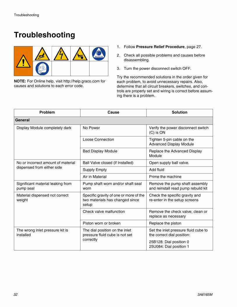
Troubleshooting
NOTE: For Online help, visit http://help.graco.com for causes and solutions to each error code.
1. Follow Pressure Relief Procedure, page 27.
2. Check all possible problems and causes before disassembling.
3. Turn the power disconnect switch OFF.
Try the recommended solutions in the order given for each problem, to avoid unnecessary repairs. Also, determine that all circuit breakers, switches, and con-trols are properly set and wiring is correct before assum-ing there is a problem.
Problem Cause Solution
General
Display Module completely dark No Power Verify the power disconnect switch (C) is ON
Loose Connection Tighten 5-pin cable on the Advanced Display Module
Bad Display Module Replace the Advanced Display Module
No or incorrect amount of material dispensed from either side
Ball Valve closed (if Installed) Open supply ball valve.
Supply Empty Add fluid
Air in Material Prime the machine
Significant material leaking from pump seal
Pump shaft worn and/or shaft seal worn
Remove the pump shaft assembly and reinstall read pump rebuild kit
Material dispensed not correct weight
Specific gravity of one or more of the two materials has changed since setup
Check the specific gravity and re-enter in the setup screens
Check valve malfunction Remove the check valve; clean or replace as necessary
Piston worn or broken Replace the piston
The wrong inlet pressure kit is installed
The dial position on the inlet pressure fluid cube is not set correctly
Set the inlet pressure fluid cube to the correct dial position:
25B128: Dial position 025U084: Dial position 1

Troubleshooting
3A6165M 33
The wrong pressure is displayed on the ADM/CGM
The dial position on the pressure fluid cube is not set correctly
Set the inlet pressure fluid cube to the correct dial position:
25B128: Dial position 025U084: Dial position 1
Incorrect pressure transducer is being used
Verify that the correct pressure transducer is being used. Change if necessary.
25B128: Use 15M669 pressure transducer25U084: Use 16P289 pressure transducer
Bad pressure transducer Replace the pressure transducer
Proportioning System
Proportioning pump does not hold pressure when stalled
Pump piston or intake valve leaking 1. Observe gauge to determine which pump is losing pressure.
2. Determine in which direction the pump has stalled by observing which directional valve indicator light is on.
3. Repair the valve.
Material imbalance Inadequate flow from pump; Increase fluid supply to proportion-ing pump:
• Use minimum 3/4 in. (19 mm) ID supply hose, as short as practi-cal
Clean inlet strainer screen
Worn pump inlet valve ball/seat or gasket
Erratic pump movement Pump cavitation Feed pump pressure is too low. Adjust pressure to maintain 100 psi (0.7 MPa, 7 bar) minimum.
Pump output low Obstructed fluid hose or dispense valve; fluid hose ID too small
Open, clear; use hose with larger ID.
Worn piston valve or intake valve in displacement pump
See pump manual 3A0019.
Inadequate feed pump pressure Check feed pump pressure and adjust to 100 psi (0.7 MPa, 7 bar) minimum.
Problem Cause Solution
Troubleshooting
34 3A6165M
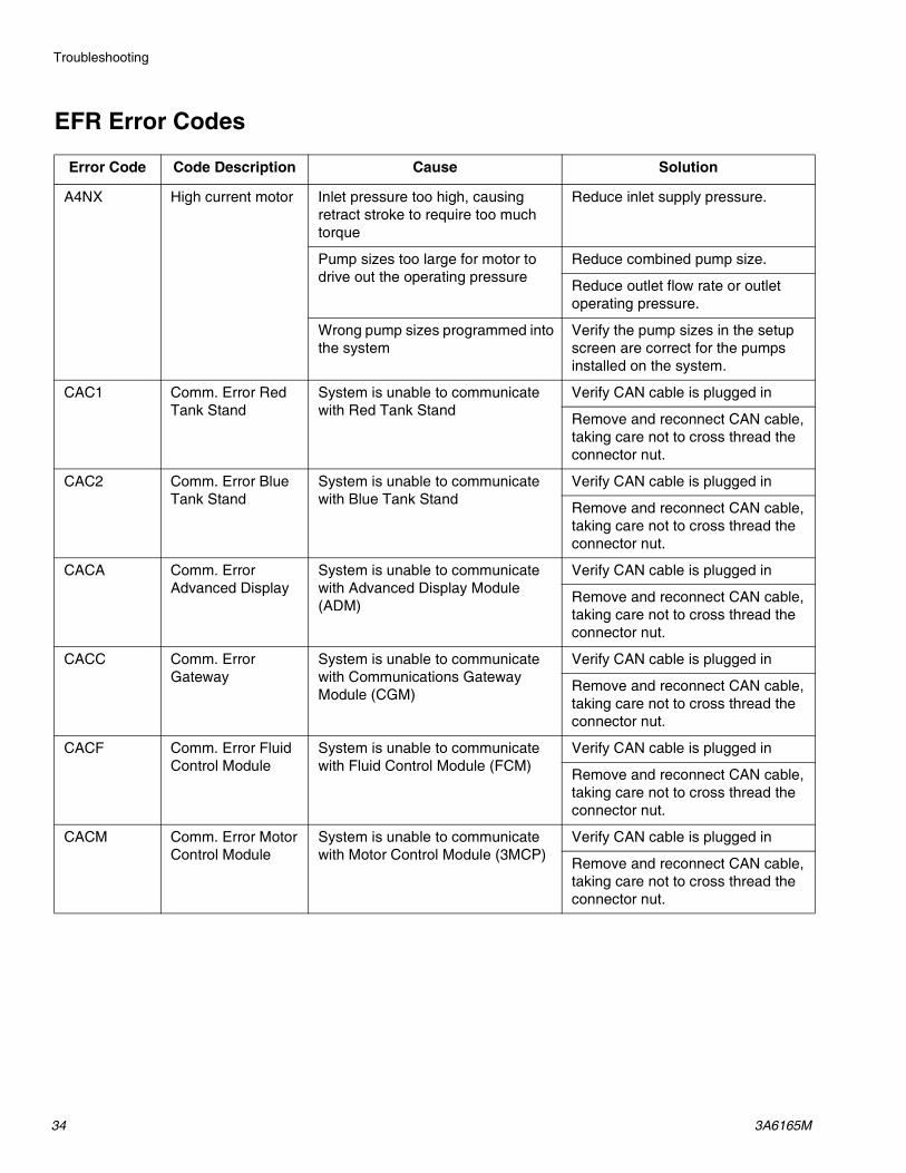
EFR Error Codes
Error Code Code Description Cause Solution
A4NX High current motor Inlet pressure too high, causing retract stroke to require too much torque
Reduce inlet supply pressure.
Pump sizes too large for motor to drive out the operating pressure
Reduce combined pump size.
Reduce outlet flow rate or outlet operating pressure.
Wrong pump sizes programmed into the system
Verify the pump sizes in the setup screen are correct for the pumps installed on the system.
CAC1 Comm. Error Red Tank Stand
System is unable to communicate with Red Tank Stand
Verify CAN cable is plugged in
Remove and reconnect CAN cable, taking care not to cross thread the connector nut.
CAC2 Comm. Error Blue Tank Stand
System is unable to communicate with Blue Tank Stand
Verify CAN cable is plugged in
Remove and reconnect CAN cable, taking care not to cross thread the connector nut.
CACA Comm. Error Advanced Display
System is unable to communicate with Advanced Display Module (ADM)
Verify CAN cable is plugged in
Remove and reconnect CAN cable, taking care not to cross thread the connector nut.
CACC Comm. Error Gateway
System is unable to communicate with Communications Gateway Module (CGM)
Verify CAN cable is plugged in
Remove and reconnect CAN cable, taking care not to cross thread the connector nut.
CACF Comm. Error Fluid Control Module
System is unable to communicate with Fluid Control Module (FCM)
Verify CAN cable is plugged in
Remove and reconnect CAN cable, taking care not to cross thread the connector nut.
CACM Comm. Error Motor Control Module
System is unable to communicate with Motor Control Module (3MCP)
Verify CAN cable is plugged in
Remove and reconnect CAN cable, taking care not to cross thread the connector nut.

Troubleshooting
3A6165M 35
CACV Comm. Error Voltex Dynamic Mix Valve Module
No 24 VDC power supply to ADM Reconnect or replace CAN cable connecting FCM and ADM. If CAN connection good, check 24V power supply wiring inside the controller enclosure. Make sure AC power to control enclosure is turned off before checking power supply. Yellow LED on FCM should be flashing.
Cross threaded CAN cable CAN cables carry 24 V DC power and communication between modules. A cross threaded CAN cable connector may cause problems with communication and/or power to modules. Carefully check for cross threaded CAN connections on the ADM and FCM. Yellow LED on FCM board should be flashing.
CCCC Comm. Error Gateway
Automation gateway lost communication with automation controller
Verify fieldbus cable is properly connected.
Verify host is communicating.
DDDA Pump Cavitation A Out of material Verify A material supply
Check valve not working properly Inspect and clean A side check valve. Check for leaking seals or damage to the ball
DDDB Pump Cavitation B Out of material Verify B material supply
Check valve not working properly Inspect and clean B side check valve. Check for leaking seals or damage to the ball
DHDA Leak Detected Outlet A
Pressure leaking from A side while stalled at pressure
Visually inspect the machine and hoses for signs of material leakage.
Inspect seals in pump and ball check.
DHDB Leak Detected Outlet B
Pressure leaking from B side while stalled at pressure
Visually inspect the machine and hoses for signs of material leakage.
Inspect seals in pump and ball check.
ECAA Air Nucleation Disabled for Dispense
The air nucleation dispense button was pressed on the home run screen and a dispense occurred.
No action necessary if desired. If not desired, press the button on the run screen again to enable the air nucleation during dispensing.
ECMA Motor Spinning Disabled for Dispense
The air nucleation dispense button was pressed on the home run screen and a dispense occurred.
No action necessary if desired. If not desired, press the button on the run screen again to enable the motor during dispensing.
Error Code Code Description Cause Solution

Troubleshooting
36 3A6165M
F3NX Unable to Maintain Flow Rate
Pump is unable to deliver the desired flow rate
Reduce flow rate
Increase pump sizes
Measure line voltage. Low line voltage may reduce maximum operating flow rate.
F4NX Setting Exceeds Max Output
Pump cannot cycle fast enough to achieve the desired flow rate
Reduce flow rate
Increase pump sizes
L1TA Red Tank Sensor Failure
Bad level sensor(s) Replace level sensor(s)
L2TA Red Low Material Tank low on material Fill tanks with material
Loose/broken connection If the tanks appear to have plenty of material, check to make sure the level sensor(s) is connected to the proper port and that the cord is not damaged.
Bad level sensor(s) Replace level sensor(s)
L3TA Red High Material Level
Defective fill valve If the tanks appear to have plenty of material, check to make sure the level sensor is connected to the proper port and that the cord is not damaged
Replace fill valve is leaking
Bad level sensor Replace level sensor
L6TA Red Auto Refill Timeout
No material is actually being fed Make sure the feed pumps are operating properly
Loose level sensor connection Check for loose or disconnected wires or plugs
Bad level sensor Replace level sensor
L1TB Blue Tank Sensor Failure
Bad level sensor(s) Replace level sensor(s)
L2TB Blue Low Material Tank low on material Fill tanks with material
Loose/broken connection If the tanks appear to have plenty of material, check to make sure the level sensor(s) is connected to the proper port and that the cord is not damaged.
Bad level sensor(s) Replace level sensor(s)
Error Code Code Description Cause Solution

Troubleshooting
3A6165M 37
L3TB Blue High Material Level
Defective fill valve If the tanks appear to have plenty of material, check to make sure the level sensor is connected to the proper port and that the cord is not damaged.
Replace fill valve is leaking
Bad level sensor Replace level sensor
L6TB Blue Auto Refill Timeout
No material is actually being fed Make sure the feed pumps are operating properly
Loose level sensor connection Check for loose or disconnected wires or plugs
Bad level sensor Replace level sensor
MAA0 Pump A Cycles Exceeds Limit Setting
The number of Pump A (or B) cycles has exceeded the limit entered on the Setup Maintenance 1 screen
Raise or enter 0 in the corresponding cycle counter limit. Set the corresponding Pump or Dispense Valve counter to 0.MAB0 Pump B Cycles
Exceeds Limit Setting
MED1 Dispense Valve Cycles Exceeds Limit Setting
The number of Dispense Valve cycles has exceeded the limit entered on the Setup Maintenance 1 screen
P1DA Low Pressure Alarm Outlet A
Pressure A is below user-defined dispense pressure limit
Check feed system for low or empty material.
Increase dispense rate.
Check pressure settings on setup screen.
P1DB Low Pressure Alarm Outlet B
Pressure B is below user-defined dispense pressure limit
Check feed system for low or empty material.
Increase dispense rate.
Check pressure settings on setup screen.
P1FA Low Pressure Alarm Inlet A
Pressure A is below user-defined dispense pressure limit
Check feed system for low or empty material.
Check feed system filters for blockage if installed.
Check for blockage in feed system.
Check pressure settings on setup screen.
Error Code Code Description Cause Solution
Troubleshooting
38 3A6165M
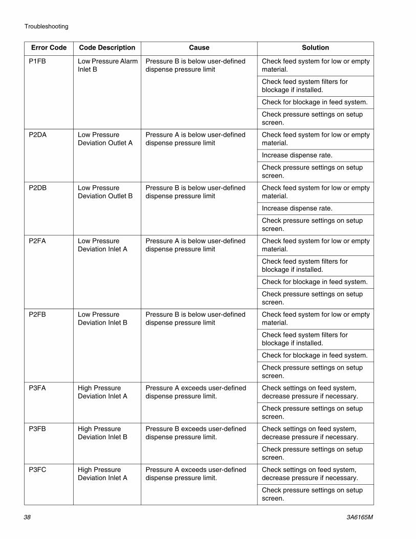
P1FB Low Pressure Alarm Inlet B
Pressure B is below user-defined dispense pressure limit
Check feed system for low or empty material.
Check feed system filters for blockage if installed.
Check for blockage in feed system.
Check pressure settings on setup screen.
P2DA Low Pressure Deviation Outlet A
Pressure A is below user-defined dispense pressure limit
Check feed system for low or empty material.
Increase dispense rate.
Check pressure settings on setup screen.
P2DB Low Pressure Deviation Outlet B
Pressure B is below user-defined dispense pressure limit
Check feed system for low or empty material.
Increase dispense rate.
Check pressure settings on setup screen.
P2FA Low Pressure Deviation Inlet A
Pressure A is below user-defined dispense pressure limit
Check feed system for low or empty material.
Check feed system filters for blockage if installed.
Check for blockage in feed system.
Check pressure settings on setup screen.
P2FB Low Pressure Deviation Inlet B
Pressure B is below user-defined dispense pressure limit
Check feed system for low or empty material.
Check feed system filters for blockage if installed.
Check for blockage in feed system.
Check pressure settings on setup screen.
P3FA High Pressure Deviation Inlet A
Pressure A exceeds user-defined dispense pressure limit.
Check settings on feed system, decrease pressure if necessary.
Check pressure settings on setup screen.
P3FB High Pressure Deviation Inlet B
Pressure B exceeds user-defined dispense pressure limit.
Check settings on feed system, decrease pressure if necessary.
Check pressure settings on setup screen.
P3FC High Pressure Deviation Inlet A
Pressure A exceeds user-defined dispense pressure limit.
Check settings on feed system, decrease pressure if necessary.
Check pressure settings on setup screen.
Error Code Code Description Cause Solution

Troubleshooting
3A6165M 39
P3FD High Pressure Deviation Inlet B
Pressure B exceeds user-defined dispense pressure limit.
Check settings on feed system, decrease pressure if necessary.
Check pressure settings on setup screen.
P3DA High Pressure Outlet A
Pressure A exceeds user-defined limit
Inspect for hardened material or obstructions to flow.
Attempt to purge material at a reduced flow rate.
Reduce operating pressure by reducing flow rate and/or restriction in the hose and valve.
Check pressure settings on setup screen.
P3DB High Pressure Outlet B
Pressure B exceeds user-defined limit
Inspect for hardened material or obstructions to flow.
Attempt to purge material at a reduced flow rate.
Reduce operating pressure by reducing flow rate and/or restriction in the hose and valve.
Check pressure settings on setup screen.
P3DC High Pressure Deviation Outlet A
Pressure A exceeds user-defined dispense pressure limit.
Inspect for hardened material or obstructions to flow.
Attempt to purge material at a reduced flow rate.
Reduce operating pressure by reducing flow rate and/or restriction in the hose and valve.
Check pressure settings on setup screen.
P3DD High Pressure Deviation Outlet B
Pressure B exceeds user-defined dispense pressure limit.
Inspect for hardened material or obstructions to flow.
Attempt to purge material at a reduced flow rate.
Reduce operating pressure by reducing flow rate and/or restriction in the hose and valve.
Check pressure settings on setup screen.
Error Code Code Description Cause Solution

Troubleshooting
40 3A6165M
P3FA High Pressure Inlet A
Supply pressure is too high Reduce inlet supply pressure. Inlet pressure should not exceed 67% of outlet pressure.
Outlet operating pressure is too low Increase outlet operating pressure. Outlet pressure should be at least 1.5x inlet pressure.
P3FB High Pressure Inlet B
Supply pressure is too high Reduce inlet supply pressure. Inlet pressure should not exceed 67% of outlet pressure.
Outlet operating pressure is too low Increase outlet operating pressure. Outlet pressure should be at least 1.5x inlet pressure.
P4DA High Pressure Outlet A
Pressure A exceeds system limit Inspect for hardened material or obstructions to flow.
Attempt to purge material at a reduced flow rate.
Reduce operating pressure by reducing flow rate and/or restriction in the hose and valve.
P4DB High Pressure Outlet B
Pressure B exceeds system limit Inspect for hardened material or obstructions to flow.
Attempt to purge material at a reduced flow rate.
Reduce operating pressure by reducing flow rate and/or restriction in the hose and valve.
P4DC High Pressure Alarm Outlet A
Pressure A exceeds user-defined dispense pressure limit.
Inspect for hardened material or obstructions to flow.
Attempt to purge material at a reduced flow rate.
Reduce operating pressure by reducing flow rate and/or restriction in the hose and valve.
P4DD High Pressure Alarm Outlet B
Pressure B exceeds user-defined dispense pressure limit.
Inspect for hardened material or obstructions to flow.
Attempt to purge material at a reduced flow rate.
Reduce operating pressure by reducing flow rate and/or restriction in the hose and valve.
Error Code Code Description Cause Solution

Troubleshooting
3A6165M 41
P4FA High Pressure Alarm Inlet A
Pressure A exceeds user-defined dispense pressure limit.
Check settings on feed system, decrease pressure if necessary.
Check pressure settings on setup screen.
P4FB High Pressure Alarm Inlet B
Pressure B exceeds user-defined dispense pressure limit.
Check settings on feed system, decrease pressure if necessary.
Check pressure settings on setup screen.
P6DA Pressure Sensor Error Outlet A
Loose or bad sensor connection to Motor Control Module
Check to make sure that the pressure sensor is properly connected to connector 6 of the Motor Control Module (MCM)
Faulty sensor Replace the Pressure Sensor
P6DB Pressure Sensor Error Outlet B
Loose or bad sensor connection to Motor Control Module
Check to make sure that the pressure sensor is properly connected to connector 5 of the Motor Control Module (MCM)
Faulty sensor Replace the Pressure Sensor
P6FA Pressure Sensor Error Inlet A
Loose or bad sensor connection to Motor Control Module
Check to make sure that the pressure sensor is properly connected to the connector 6 of the Fluid Control Module (FCM).
Faulty sensor Replace the Pressure Sensor
P6FB Pressure Sensor Error Inlet B
Loose or bad sensor connection to Motor Control Module
Check to make sure that the pressure sensor is properly connected to connector 5 of the Fluid Control Module (FCM).
Faulty sensor Replace the Pressure Sensor
P7DA Pressure Imbalance High A
Dispense line is clogged First try purging fresh material through the system. Then relieve pressure and check for cured material or obstructions in the dispense valve.
Orifice restrictions sized incorrectly Adjust orifice restrictions to balance pressure of A and B materials
Out of material Verify B material supply
Pressure imbalance is defined too low
Increase pressure imbalance amount from the Setup screen of the Advanced Display Module (ADM)
Error Code Code Description Cause Solution

Troubleshooting
42 3A6165M
P7DB Pressure Imbalance High B
Dispense line is clogged First try purging fresh material through the system. Then relieve pressure and check for cured material or obstructions in the dispense valve.
Orifice restrictions sized incorrectly Adjust orifice restrictions to balance pressure of A and B materials
Out of material Verify A material supply
Pressure imbalance is defined too low
Increase pressure imbalance amount from the Setup screen of the Advanced Display Module (ADM)
T4NX High Temperature Motor
Cooling fans not working properly Ensure cooling fans are clear of obstructions and operating properly
V1NX Low Voltage Motor AC voltage is too low Check wire connections and verify line voltage is within specification
V4NX High Voltage Motor AC voltage is too high Verify line voltage is within specification
WBNX Encoder Error Motor Encoder not plugged in Ensure encoder connector is fully plugged into the circuit board inside the driver
Faulty encoder Replace encoder
WMNX Controller Fault Motor
Faulty circuit board Replace motor control circuit board
WVCX Voltex Dynamic Mix Valve Motor Fault
Over Torque Cycle Power. Increase Ramp up time. Cycle power to unit.
Clean mixer. Cycle power to unit.
No power to motor Make sure that motor has power. Check power supply if need cycle power.
W5NX Encoder Calibration Motor
Encoder not calibrated Calibrate the Encoder from the maintenance screen of the Advanced Display Module (ADM)
Error Code Code Description Cause Solution
Parts
3A6165M 43
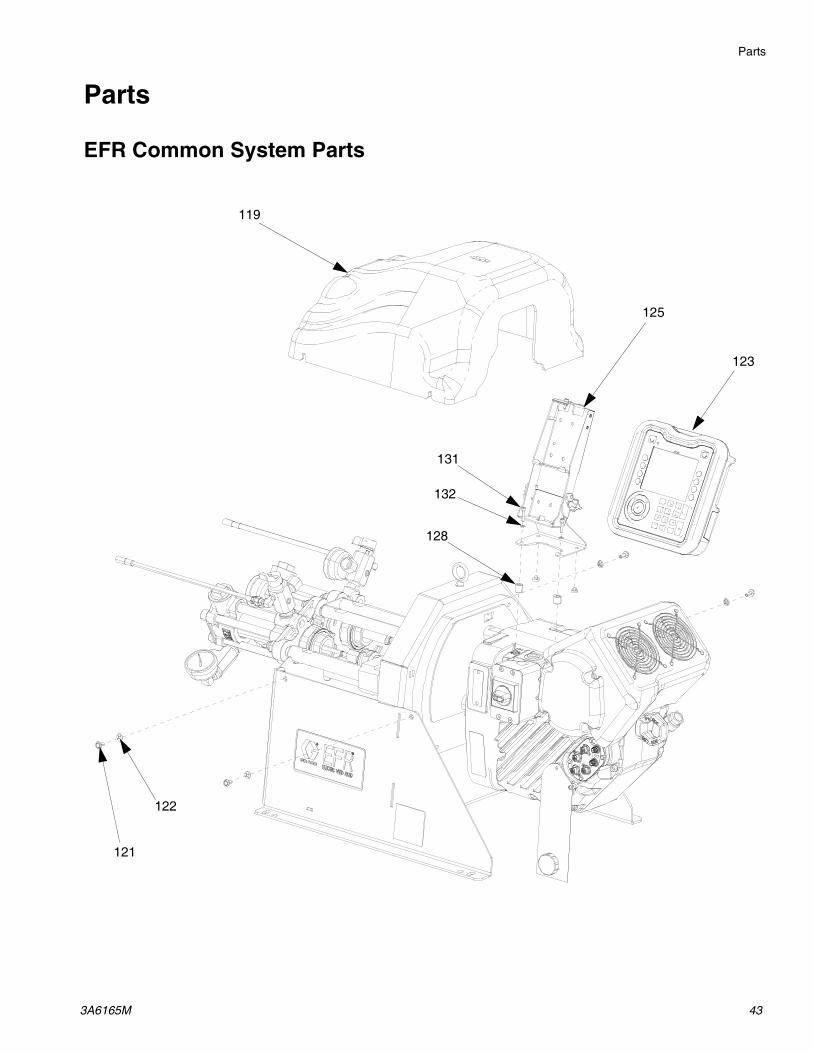
Parts
EFR Common System Parts
119
125
121
122
131
132
128
123
Parts
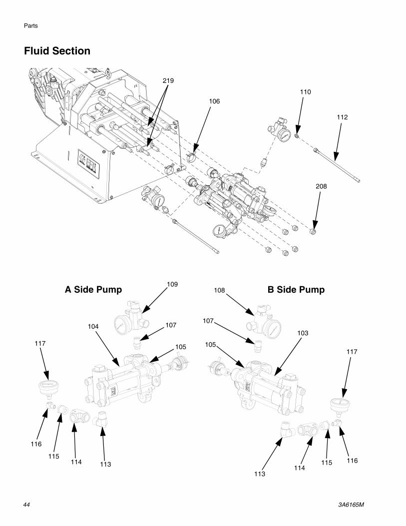
44 3A6165M
Fluid Section
106110
112
117
116115114
113
103
108
107
109
107104
116
115114 113
117
A Side Pump B Side Pump
208
105 105
219

Parts
3A6165M 45
Driver and Yoke Assembly201
202206 204
208
207
203
205
Apply blue thread-locker.
Torque to 0.8-1.13 N•m (7-10 in-lbs).
Torque to 20-27 N•m (15-20 ft-lbs).
Torque to 23-32 N•m (17-23 ft-lbs).
Torque to 67-81 N•m (50-60 ft-lbs).
Torque adapters to 122-135 N•m (90-100 ft-lbs).
Torque to 196-210 N•m (145-155 ft-lbs).
Press fit bushings into sleeve until flush.
Orient yoke group as shown for assembly. Slide yoke group onto adapter, then install tie rods.
1
2
3
4
5
6
7
8
9
4
217
218
216 214
212
2159
1 5
1 6
9
Detail B
See Detail B
2101 7
211
239
238
1
239
235
236
237
241
1 4
1 4
209
251
234
4
Parts
46 3A6165M
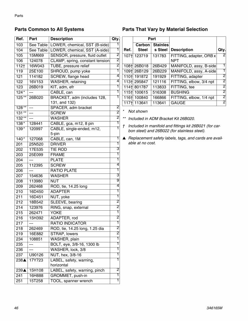
Parts Common to All Systems Parts That Vary by Material Selection
* Not shown
** Included in ADM Bracket Kit 26B020.
† Included in manifold and fittings kit 26B021 (for car-bon steel) and 26B022 (for stainless steel).
▲ Replacement safety labels, tags, and cards are avail-able at no cost.
Ref. Part Description Qty.103 See Table LOWER, chemical, SST (B-side) 1104 See Table LOWER, chemical, SST (A-side) 1105 15M669 SENSOR, pressure, fluid outlet 2106 124078 CLAMP, spring, constant tension 2112† 16W043 TUBE, pressure relief 2119 25E100 SHROUD, pump yoke 1121 114182 SCREW, flange head 4122 16V153 WASHER, retaining 4123 26B019 KIT, adm, efr 1124* --- CABLE, can 1125** 26B020 BRACKET, adm (includes 128,
131, and 132)1
128** --- SPACER, adm bracket 2131** --- SCREW 2132** --- WASHER 2138* 128441 CABLE, gca, m12, 8 pin 1139* 120997 CABLE, single-ended, m12,
5-pin1
140* 127068 CABLE, can, 1M 1201 25N520 DRIVER 1202 17E535 TIE ROD 3203 25E099 FRAME 1204 --- PLATE 1205 112395 SCREW 4206 --- RATIO PLATE 1207 154636 WASHER 3208 113980 NUT 9209 262468 ROD, tie, 14.25 long 4210 16D450 ADAPTER 1211 16D451 NUT, yoke 1212 18B542 SLEEVE, bearing 2214 123976 RING, snap, external 2215 262471 YOKE 1216 15H392 ADAPTER, rod 2217 --- RATIO INDICATOR 1218 262469 ROD, tie, 14.25 long, 1.25 dia 2219 16E882 STRAP, lowers 2234 108851 WASHER, plain 1235 --- BOLT, eye, 3/8-16, 1300 lb 1236 --- WASHER, lock, 3/8 1237 U90126 NUT, hex, 3/8-16 1238▲ 17Y723 LABEL, safety, warning,
horizontal1
239▲ 15H108 LABEL, safety, warning, pinch 2241 16H888 GROMMET, push-in 1251 15T258 TOOL, spanner wrench 1
Ref.
Part
Description Qty.Carbon
SteelStainless Steel
107† 123719 131783 FITTING, adapter, ORB x NPT
2
108† 26B018 26B429 MANIFOLD, assy, B-side 1109† 26B129 26B229 MANIFOLD, assy, A-side 1110† 191872 191929 FITTING, adapter 2113† 295847 121116 FITTING, elbow, 3/4 npt 2114† 801787 113833 FITTING, tee 2115† 100615 516308 BUSHING 2116† 100840 166866 FITTING, elbow, 1/4 npt 2117† 113641 113641 GAUGE 2

Parts
3A6165M 47
Electrical Assembly
* Not shown† Included in Transformer Kit 26A703▲ Replacement safety labels, tags, and cards are avail-
able at no cost.
220
221
231229
228
222
223224
225226
227
230
32
233
232
234
Ref. Description
240V Systems
480 V Systems
Part Qty. Part Qty.220 COVER, pump, lower 25E103 1 25E103 1
221† SCREW 114182 4 114182 8
222 JUNCTION BOX --- 1 --- 1
223 SCREW 117080 4 117080 4
224 SWITCH, disconnect, 40A
123970 1 123970 1
225 COVER, junction box --- 1 --- 1
226 SCREW 113768 4 113768 4
227 KNOB, disconnect, panel
--- 1 --- 1
228▲ LABEL, caution 189930 1 189930 1
229† PLUG, headless 3/4 npt 102726 1 --- -
FITTING, conduit, 3/4 npt
--- - --- 1
230† TRANSFORMER, 480V --- - --- 1
231 CORD GRIP, strain relief, 3/4-14 NPT male, cable range 0.35-0.63 in. (8.9-16 mm)
121171 1 121171 1
232† BUSHING, strain relief, 1”
--- - 126881 1
233▲† LABEL, safety, danger --- - 25E178 1
234† NUT, strain relief, 1” --- - 126891 1
240*† HARNESS, transformer, efr
--- - --- 1
Ref. Description
240V Systems
480 V Systems
Part Qty. Part Qty.

Accessories
48 3A6165M
AccessoriesNOTE: See the MD2 Valve Instructions-Parts manual for more information on mixers and accessories.
Voltex Dynamic Mix Valve
Applicator
Dispense Valve Interface Kit
Inlet Regulator Kits
Additional AccessoriesMiscellaneous
Communications Gateway Module (CGM)
The EFR Communication Gateway Module allows the user to control an EFR through an external control device such as a PLC. See EFR Communication Gate-way Module manual for more information.
Part Description25T670 Voltex Dynamic Mix Valve
25T750 Voltex Dynamic Mix Valve, Integrated
Part Description255179 Valve, Dispense, 1:1, Soft Seats
255180 Valve, Dispense, 1:1, Hard Seats
255181 Valve, Dispense, 10:1, Soft Seats
255182 Valve, Dispense, 10:1, Hard Seats
Part Description
26C485 MD2 Valve Solenoid, with cable
Part Description
26A704 SS Mastic Regulator Kit with fittings
26A705 CS Mastic Regulator Kit with fittings
Part Description
121728 Extension Cable for ADM, 4 meter
255244 Foot Switch with Guard and 4 meter Cable
17Z431 4 meter adapter cable for foot switch, 8-pin to 4-pin
120997 4 meter M12 pigtail cable (for valve control or sequence select)
128441 4 meter 8-pin M12 pigtail Integration/Trigger Cable
127948 Splitter cable, 3x 8-pin M12
Part Description
25B127 DeviceNet CGM Kit
26A700 EtherNet/IP CGM Kit
26A701 PROFIBUS CGM Kit
26A702 PROFINET CGM Kit
Accessories
3A6165M 49
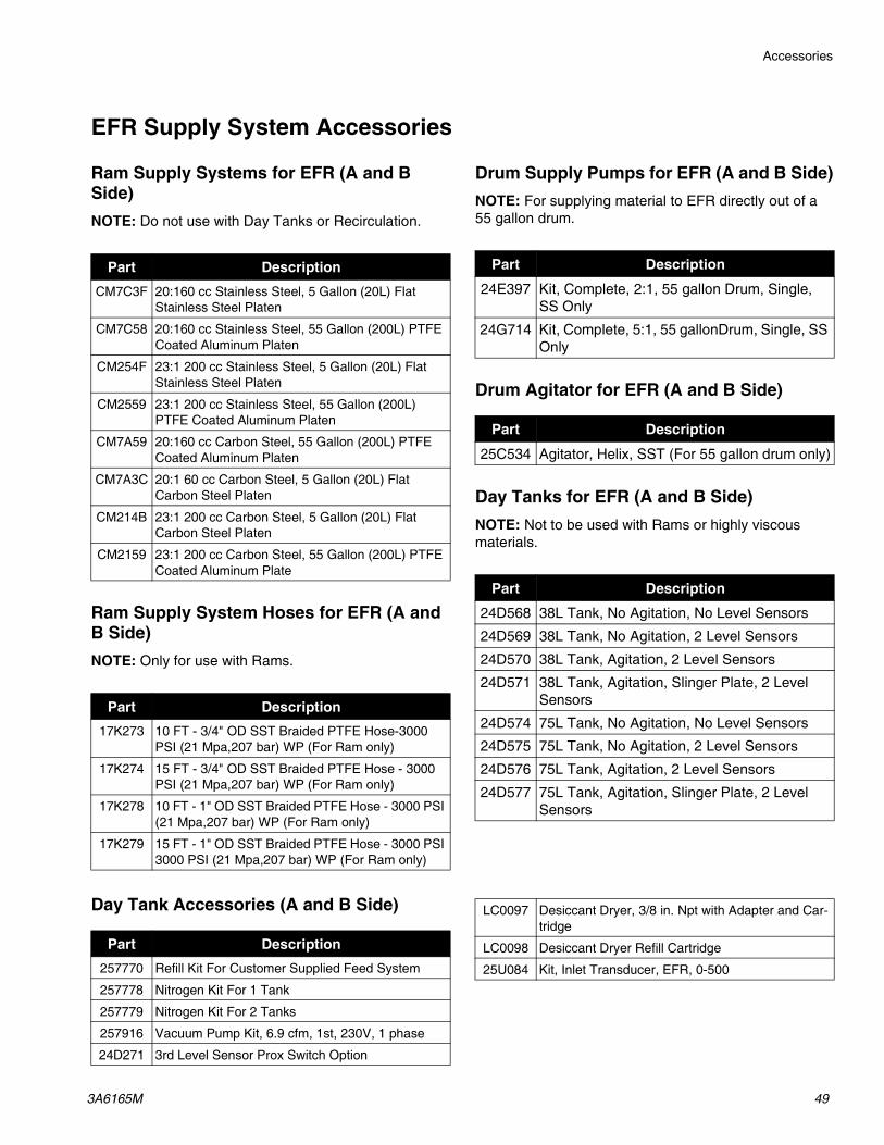
EFR Supply System Accessories
Ram Supply Systems for EFR (A and B Side)NOTE: Do not use with Day Tanks or Recirculation.
Ram Supply System Hoses for EFR (A and B Side)NOTE: Only for use with Rams.
Drum Supply Pumps for EFR (A and B Side)NOTE: For supplying material to EFR directly out of a 55 gallon drum.
Drum Agitator for EFR (A and B Side)
Day Tanks for EFR (A and B Side)NOTE: Not to be used with Rams or highly viscous materials.
Day Tank Accessories (A and B Side)
Part Description
CM7C3F 20:160 cc Stainless Steel, 5 Gallon (20L) Flat Stainless Steel Platen
CM7C58 20:160 cc Stainless Steel, 55 Gallon (200L) PTFE Coated Aluminum Platen
CM254F 23:1 200 cc Stainless Steel, 5 Gallon (20L) Flat Stainless Steel Platen
CM2559 23:1 200 cc Stainless Steel, 55 Gallon (200L) PTFE Coated Aluminum Platen
CM7A59 20:160 cc Carbon Steel, 55 Gallon (200L) PTFE Coated Aluminum Platen
CM7A3C 20:1 60 cc Carbon Steel, 5 Gallon (20L) Flat Carbon Steel Platen
CM214B 23:1 200 cc Carbon Steel, 5 Gallon (20L) Flat Carbon Steel Platen
CM2159 23:1 200 cc Carbon Steel, 55 Gallon (200L) PTFE Coated Aluminum Plate
Part Description17K273 10 FT - 3/4" OD SST Braided PTFE Hose-3000
PSI (21 Mpa,207 bar) WP (For Ram only)
17K274 15 FT - 3/4" OD SST Braided PTFE Hose - 3000 PSI (21 Mpa,207 bar) WP (For Ram only)
17K278 10 FT - 1" OD SST Braided PTFE Hose - 3000 PSI (21 Mpa,207 bar) WP (For Ram only)
17K279 15 FT - 1" OD SST Braided PTFE Hose - 3000 PSI 3000 PSI (21 Mpa,207 bar) WP (For Ram only)
Part Description
24E397 Kit, Complete, 2:1, 55 gallon Drum, Single, SS Only
24G714 Kit, Complete, 5:1, 55 gallonDrum, Single, SS Only
Part Description
25C534 Agitator, Helix, SST (For 55 gallon drum only)
Part Description
24D568 38L Tank, No Agitation, No Level Sensors
24D569 38L Tank, No Agitation, 2 Level Sensors
24D570 38L Tank, Agitation, 2 Level Sensors
24D571 38L Tank, Agitation, Slinger Plate, 2 Level Sensors
24D574 75L Tank, No Agitation, No Level Sensors
24D575 75L Tank, No Agitation, 2 Level Sensors
24D576 75L Tank, Agitation, 2 Level Sensors
24D577 75L Tank, Agitation, Slinger Plate, 2 Level Sensors
Part Description257770 Refill Kit For Customer Supplied Feed System
257778 Nitrogen Kit For 1 Tank
257779 Nitrogen Kit For 2 Tanks
257916 Vacuum Pump Kit, 6.9 cfm, 1st, 230V, 1 phase
24D271 3rd Level Sensor Prox Switch Option
LC0097 Desiccant Dryer, 3/8 in. Npt with Adapter and Car-tridge
LC0098 Desiccant Dryer Refill Cartridge
25U084 Kit, Inlet Transducer, EFR, 0-500
Accessories
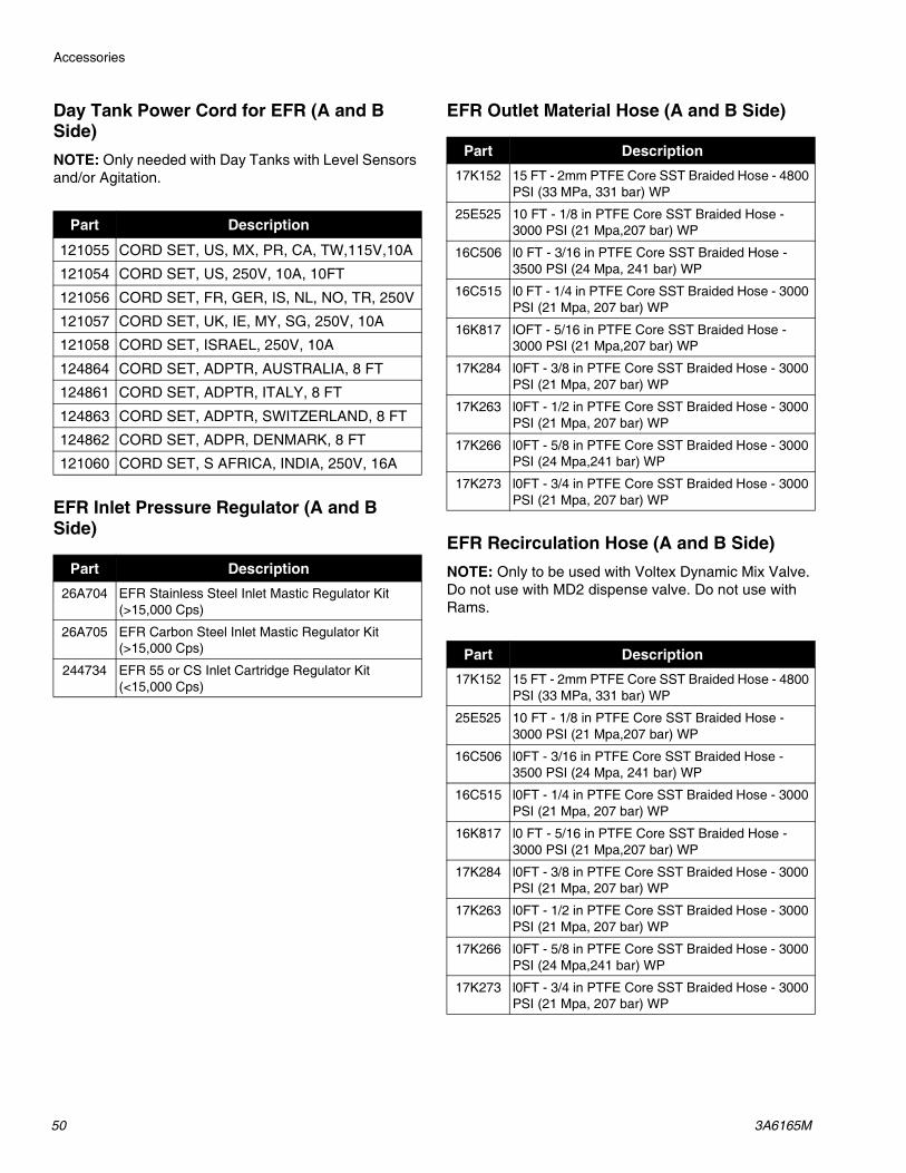
50 3A6165M
Day Tank Power Cord for EFR (A and B Side)NOTE: Only needed with Day Tanks with Level Sensors and/or Agitation.
EFR Inlet Pressure Regulator (A and B Side)
EFR Outlet Material Hose (A and B Side)
EFR Recirculation Hose (A and B Side)NOTE: Only to be used with Voltex Dynamic Mix Valve. Do not use with MD2 dispense valve. Do not use with Rams.
Part Description
121055 CORD SET, US, MX, PR, CA, TW,115V,10A
121054 CORD SET, US, 250V, 10A, 10FT
121056 CORD SET, FR, GER, IS, NL, NO, TR, 250V
121057 CORD SET, UK, IE, MY, SG, 250V, 10A
121058 CORD SET, ISRAEL, 250V, 10A
124864 CORD SET, ADPTR, AUSTRALIA, 8 FT
124861 CORD SET, ADPTR, ITALY, 8 FT
124863 CORD SET, ADPTR, SWITZERLAND, 8 FT
124862 CORD SET, ADPR, DENMARK, 8 FT
121060 CORD SET, S AFRICA, INDIA, 250V, 16A
Part Description26A704 EFR Stainless Steel Inlet Mastic Regulator Kit
(>15,000 Cps)
26A705 EFR Carbon Steel Inlet Mastic Regulator Kit (>15,000 Cps)
244734 EFR 55 or CS Inlet Cartridge Regulator Kit (<15,000 Cps)
Part Description17K152 15 FT - 2mm PTFE Core SST Braided Hose - 4800
PSI (33 MPa, 331 bar) WP
25E525 10 FT - 1/8 in PTFE Core SST Braided Hose - 3000 PSI (21 Mpa,207 bar) WP
16C506 l0 FT - 3/16 in PTFE Core SST Braided Hose - 3500 PSI (24 Mpa, 241 bar) WP
16C515 l0 FT - 1/4 in PTFE Core SST Braided Hose - 3000 PSI (21 Mpa, 207 bar) WP
16K817 lOFT - 5/16 in PTFE Core SST Braided Hose - 3000 PSI (21 Mpa,207 bar) WP
17K284 l0FT - 3/8 in PTFE Core SST Braided Hose - 3000 PSI (21 Mpa, 207 bar) WP
17K263 l0FT - 1/2 in PTFE Core SST Braided Hose - 3000 PSI (21 Mpa, 207 bar) WP
17K266 l0FT - 5/8 in PTFE Core SST Braided Hose - 3000 PSI (24 Mpa,241 bar) WP
17K273 l0FT - 3/4 in PTFE Core SST Braided Hose - 3000 PSI (21 Mpa, 207 bar) WP
Part Description17K152 15 FT - 2mm PTFE Core SST Braided Hose - 4800
PSI (33 MPa, 331 bar) WP
25E525 10 FT - 1/8 in PTFE Core SST Braided Hose - 3000 PSI (21 Mpa,207 bar) WP
16C506 l0FT - 3/16 in PTFE Core SST Braided Hose - 3500 PSI (24 Mpa, 241 bar) WP
16C515 l0FT - 1/4 in PTFE Core SST Braided Hose - 3000 PSI (21 Mpa, 207 bar) WP
16K817 l0 FT - 5/16 in PTFE Core SST Braided Hose - 3000 PSI (21 Mpa,207 bar) WP
17K284 l0FT - 3/8 in PTFE Core SST Braided Hose - 3000 PSI (21 Mpa, 207 bar) WP
17K263 l0FT - 1/2 in PTFE Core SST Braided Hose - 3000 PSI (21 Mpa, 207 bar) WP
17K266 l0FT - 5/8 in PTFE Core SST Braided Hose - 3000 PSI (24 Mpa,241 bar) WP
17K273 l0FT - 3/4 in PTFE Core SST Braided Hose - 3000 PSI (21 Mpa, 207 bar) WP

Accessories
3A6165M 51
ApplicatorsNOTE: Recirculation can only be with the Voltex Dynamic Mix Valve.
MD2 Dispense Valve Options
MD2 Dispense Valve Accessories
Part Description255179 1:1 MD2 Valve with Soft Seats (Do not use with
recirculation)
255180 1:1 MD2 Valve Hard Seats (Do not use with recir-culation)
255181 10:1 MD2 Valve with Soft Seats (Do not use with recirculation)
255182 10:1 MD2 Valve with Hard Seats (Do not use with recirculation)
25U256 Voltex with Table Top Controller (Do not use with recirculation)
25U257 Voltex with Wall Mount Controller (Do not use with recirculation)
25U258 Voltex with Table Top Controller and Recirculation
25U259 Voltex with Wall Mount Controller and Recircula-tion
Part Description255208 MD2 Dispense Valve Electric Handle
255244 Foot Switch Assembly with 4M Cord
255249 MD2 Dispense Valve Lever
Part Description258185 Orifice Kits
LC0077 3/16 x 32 ELEMENT MIXER - QTY (SO)
LC0078 1/4 x 24 ELEMENT MIXERS - QTY (50)
LC0079 3/8 x 24 ELEMENT MIXERS - QTY (50)
LC0080 3/8 x 36 ELEMENT MIXERS - QTY (50)
LC0081 3/8 Combo MIXERS - QTY (50)
LC0082 3/16 x 32ELEMENT MIXERS with Luer Lock - QTY (SO)
LC0083 1/4 X 24 ELEMENT MIXERS Luer Lock - QTY (50)
60/0111-1/50 1/2 x 24 ELEMENT MIXERS - QTY (1)
60/0117-1/50 1/2 x 36 ELEMENT MIXERS - QTY (1)
LC0084 3/16 x 32 ELEMENT MIXER - QTY (250)
LC0085 1/4 x 24 ELEMENT MIXERS - QTY (250)
LC0086 3/8 x 24 ELEMENT MIXERS - QTY (250)
LC0087 3/8 x 36 ELEMENT MIXERS - QTY (250)
LC0088 3/8 Combo MIXERS - QTY (250)
LC0089 3/16 x 32ELEMENT MIXERS with Luer Lock - QTY (250)
LC0090 1/4 X 24 ELEMENT MIXERS Luer Lock - QTY (250)
LC0063 Shroud and QTY (10) 3/16 x 32 ELEMENT MIXERS
LC0057 Shroud and QTY (10) 1/4 x 24 ELEMENT MIX-ERS
LC0058 Shroud and QTY (10) 3/8 x 24 ELEMENT MIX-ERS
LC0059 Shroud and QTY (10) 3/8 x 36 ELEMENT MIX-ERS
LC0060 Shroud and QTY (10) 3/8 Combo MIXERS
LC0061 Shroud and QTY (10) 3/16 x 32 ELEMENT MIXERS with Luer Lock
LC0062 Shroud and QTY (10) 1/4 X 24 ELEMENT MIX-ERS Luer Lock
LC0295 Shroud and QTY (10) 1/2 x 24 ELEMENT MIX-ERS
LC0296 Shroud and QTY (10) 1/2 x 36 ELEMENT MIX-ERS
258123 EFR Check Valve Kit
258124 EFR Check Valve Rebuild Kit
258128 EFR Inlet Pressure Transducer Kit
25U084 EFR Inlet Pressure Transducer Kit
25B127 EFR CGM DEVICENET KIT
26A700 EFR CGM ETHERNET IP KIT
26A701 EFR CGM PROFIBUS KIT
26A702 EFR CGM PROFINET KIT
26A703 EFR TRANSFORMER KIT
25N520 EFR HORIZONTAL DRIVER KIT
268020 EFR ADM BRACKET KIT
255244 FOOT SWITCH ASSEMBLY WITH 4M CORD
121728 CAN Cable for remote placement of ADM (4.0M)
123660 6m Extension Cord for Electric MD2 Valve Handle
Accessories
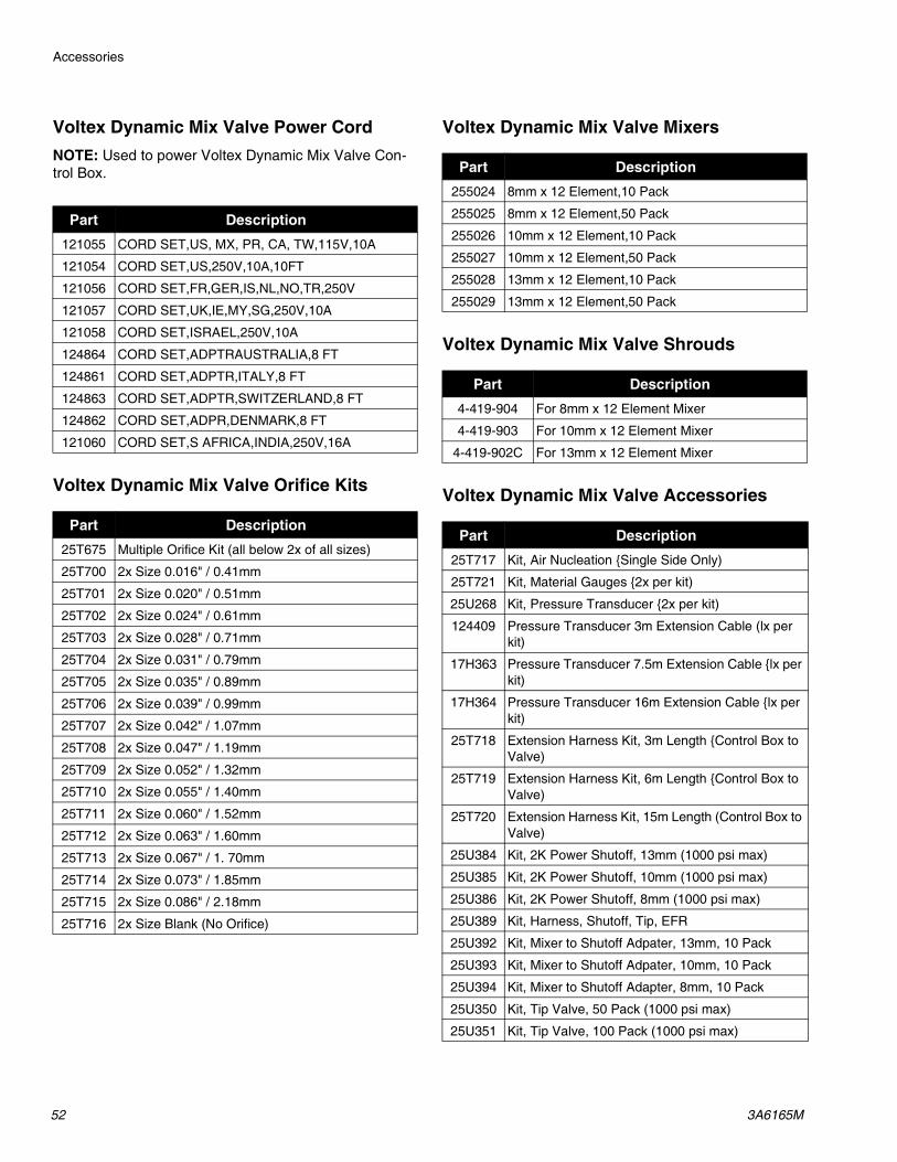
52 3A6165M
Voltex Dynamic Mix Valve Power CordNOTE: Used to power Voltex Dynamic Mix Valve Con-trol Box.
Voltex Dynamic Mix Valve Orifice Kits
Voltex Dynamic Mix Valve Mixers
Voltex Dynamic Mix Valve Shrouds
Voltex Dynamic Mix Valve Accessories
Part Description121055 CORD SET,US, MX, PR, CA, TW,115V,10A
121054 CORD SET,US,250V,10A,10FT
121056 CORD SET,FR,GER,IS,NL,NO,TR,250V
121057 CORD SET,UK,IE,MY,SG,250V,10A
121058 CORD SET,ISRAEL,250V,10A
124864 CORD SET,ADPTRAUSTRALIA,8 FT
124861 CORD SET,ADPTR,ITALY,8 FT
124863 CORD SET,ADPTR,SWITZERLAND,8 FT
124862 CORD SET,ADPR,DENMARK,8 FT
121060 CORD SET,S AFRICA,INDIA,250V,16A
Part Description25T675 Multiple Orifice Kit (all below 2x of all sizes)
25T700 2x Size 0.016" / 0.41mm
25T701 2x Size 0.020" / 0.51mm
25T702 2x Size 0.024" / 0.61mm
25T703 2x Size 0.028" / 0.71mm
25T704 2x Size 0.031" / 0.79mm
25T705 2x Size 0.035" / 0.89mm
25T706 2x Size 0.039" / 0.99mm
25T707 2x Size 0.042" / 1.07mm
25T708 2x Size 0.047" / 1.19mm
25T709 2x Size 0.052" / 1.32mm
25T710 2x Size 0.055" / 1.40mm
25T711 2x Size 0.060" / 1.52mm
25T712 2x Size 0.063" / 1.60mm
25T713 2x Size 0.067" / 1. 70mm
25T714 2x Size 0.073" / 1.85mm
25T715 2x Size 0.086" / 2.18mm
25T716 2x Size Blank (No Orifice)
Part Description255024 8mm x 12 Element,10 Pack
255025 8mm x 12 Element,50 Pack
255026 10mm x 12 Element,10 Pack
255027 10mm x 12 Element,50 Pack
255028 13mm x 12 Element,10 Pack
255029 13mm x 12 Element,50 Pack
Part Description4-419-904 For 8mm x 12 Element Mixer
4-419-903 For 10mm x 12 Element Mixer
4-419-902C For 13mm x 12 Element Mixer
Part Description25T717 Kit, Air Nucleation {Single Side Only)
25T721 Kit, Material Gauges {2x per kit)
25U268 Kit, Pressure Transducer {2x per kit)
124409 Pressure Transducer 3m Extension Cable (lx per kit)
17H363 Pressure Transducer 7.5m Extension Cable {lx per kit)
17H364 Pressure Transducer 16m Extension Cable {lx per kit)
25T718 Extension Harness Kit, 3m Length {Control Box to Valve)
25T719 Extension Harness Kit, 6m Length {Control Box to Valve)
25T720 Extension Harness Kit, 15m Length (Control Box to Valve)
25U384 Kit, 2K Power Shutoff, 13mm (1000 psi max)
25U385 Kit, 2K Power Shutoff, 10mm (1000 psi max)
25U386 Kit, 2K Power Shutoff, 8mm (1000 psi max)
25U389 Kit, Harness, Shutoff, Tip, EFR
25U392 Kit, Mixer to Shutoff Adpater, 13mm, 10 Pack
25U393 Kit, Mixer to Shutoff Adpater, 10mm, 10 Pack
25U394 Kit, Mixer to Shutoff Adapter, 8mm, 10 Pack
25U350 Kit, Tip Valve, 50 Pack (1000 psi max)
25U351 Kit, Tip Valve, 100 Pack (1000 psi max)
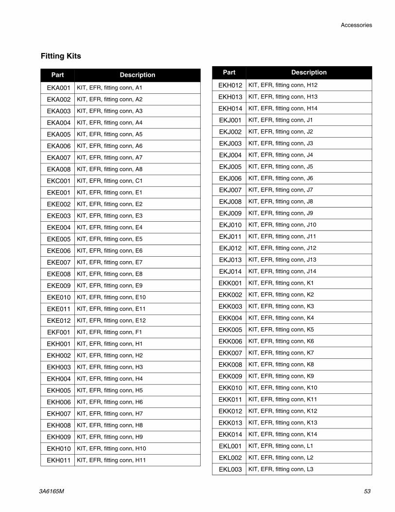
Accessories
3A6165M 53
Fitting Kits
Part Description
EKA001 KIT, EFR, fitting conn, A1
EKA002 KIT, EFR, fitting conn, A2
EKA003 KIT, EFR, fitting conn, A3
EKA004 KIT, EFR, fitting conn, A4
EKA005 KIT, EFR, fitting conn, A5
EKA006 KIT, EFR, fitting conn, A6
EKA007 KIT, EFR, fitting conn, A7
EKA008 KIT, EFR, fitting conn, A8
EKC001 KIT, EFR, fitting conn, C1
EKE001 KIT, EFR, fitting conn, E1
EKE002 KIT, EFR, fitting conn, E2
EKE003 KIT, EFR, fitting conn, E3
EKE004 KIT, EFR, fitting conn, E4
EKE005 KIT, EFR, fitting conn, E5
EKE006 KIT, EFR, fitting conn, E6
EKE007 KIT, EFR, fitting conn, E7
EKE008 KIT, EFR, fitting conn, E8
EKE009 KIT, EFR, fitting conn, E9
EKE010 KIT, EFR, fitting conn, E10
EKE011 KIT, EFR, fitting conn, E11
EKE012 KIT, EFR, fitting conn, E12
EKF001 KIT, EFR, fitting conn, F1
EKH001 KIT, EFR, fitting conn, H1
EKH002 KIT, EFR, fitting conn, H2
EKH003 KIT, EFR, fitting conn, H3
EKH004 KIT, EFR, fitting conn, H4
EKH005 KIT, EFR, fitting conn, H5
EKH006 KIT, EFR, fitting conn, H6
EKH007 KIT, EFR, fitting conn, H7
EKH008 KIT, EFR, fitting conn, H8
EKH009 KIT, EFR, fitting conn, H9
EKH010 KIT, EFR, fitting conn, H10
EKH011 KIT, EFR, fitting conn, H11
EKH012 KIT, EFR, fitting conn, H12
EKH013 KIT, EFR, fitting conn, H13
EKH014 KIT, EFR, fitting conn, H14
EKJ001 KIT, EFR, fitting conn, J1
EKJ002 KIT, EFR, fitting conn, J2
EKJ003 KIT, EFR, fitting conn, J3
EKJ004 KIT, EFR, fitting conn, J4
EKJ005 KIT, EFR, fitting conn, J5
EKJ006 KIT, EFR, fitting conn, J6
EKJ007 KIT, EFR, fitting conn, J7
EKJ008 KIT, EFR, fitting conn, J8
EKJ009 KIT, EFR, fitting conn, J9
EKJ010 KIT, EFR, fitting conn, J10
EKJ011 KIT, EFR, fitting conn, J11
EKJ012 KIT, EFR, fitting conn, J12
EKJ013 KIT, EFR, fitting conn, J13
EKJ014 KIT, EFR, fitting conn, J14
EKK001 KIT, EFR, fitting conn, K1
EKK002 KIT, EFR, fitting conn, K2
EKK003 KIT, EFR, fitting conn, K3
EKK004 KIT, EFR, fitting conn, K4
EKK005 KIT, EFR, fitting conn, K5
EKK006 KIT, EFR, fitting conn, K6
EKK007 KIT, EFR, fitting conn, K7
EKK008 KIT, EFR, fitting conn, K8
EKK009 KIT, EFR, fitting conn, K9
EKK010 KIT, EFR, fitting conn, K10
EKK011 KIT, EFR, fitting conn, K11
EKK012 KIT, EFR, fitting conn, K12
EKK013 KIT, EFR, fitting conn, K13
EKK014 KIT, EFR, fitting conn, K14
EKL001 KIT, EFR, fitting conn, L1
EKL002 KIT, EFR, fitting conn, L2
EKL003 KIT, EFR, fitting conn, L3
Part Description

Accessories
54 3A6165M
EKL004 KIT, EFR, fitting conn, L4
EKL005 KIT, EFR, fitting conn, L5
EKL006 KIT, EFR, fitting conn, L6
EKL007 KIT, EFR, fitting conn, L7
EKL008 KIT, EFR, fitting conn, L8
EKL009 KIT, EFR, fitting conn, L9
EKL010 KIT, EFR, fitting conn, L10
EKL011 KIT, EFR, fitting conn, L11
EKL012 KIT, EFR, fitting conn, L12
EKL013 KIT, EFR, fitting conn, L13
EKL014 KIT, EFR, fitting conn, L14
EKM001 KIT, EFR, fitting conn, M1
EKM002 KIT, EFR, fitting conn, M2
EKM003 KIT, EFR, fitting conn, M3
EKM004 KIT, EFR, fitting conn, M4
EKM005 KIT, EFR, fitting conn, M5
EKM006 KIT, EFR, fitting conn, M6
EKM007 KIT, EFR, fitting conn, M7
EKM008 KIT, EFR, fitting conn, M8
EKM009 KIT, EFR, fitting conn, M9
EKM010 KIT, EFR, fitting conn, M10
EKM011 KIT, EFR, fitting conn, M11
EKM012 KIT, EFR, fitting conn, M12
EKM013 KIT, EFR, fitting conn, M13
EKM014 KIT, EFR, fitting conn, M14
EKN001 KIT, EFR, fitting conn, N1
EKN002 KIT, EFR, fitting conn, N2
EKN003 KIT, EFR, fitting conn, N3
EKN004 KIT, EFR, fitting conn, N4
EKN005 KIT, EFR, fitting conn, N5
EKN006 KIT, EFR, fitting conn, N6
EKN007 KIT, EFR, fitting conn, N7
EKN008 KIT, EFR, fitting conn, N8
EKN009 KIT, EFR, fitting conn, N9
EKN010 KIT, EFR, fitting conn, N10
EKN011 KIT, EFR, fitting conn, N11
Part Description
EKN012 KIT, EFR, fitting conn, N12
EKN013 KIT, EFR, fitting conn, N13
EKN014 KIT, EFR, fitting conn, N14
Part Description

Advanced Display Module (ADM) Operation
3A6165M 55
Advanced Display Module (ADM) OperationWhen main power is turned on by turning the power dis-connect switch (C) to the ON position, the splash screen will be displayed until communication and initialization is complete.
To begin using the ADM, the machine must be on and enabled. To verify the machine is enabled, verify the System Status Indicator Light (AB) is illuminated green, see FIG. 4 on page 11. If the System Status Indicator Light is not green, press the ADM Power On/Off (AA)
button . The System Status Indicator Light will illu-minate yellow if the machine is disabled.
Perform the following tasks to fully setup your system.
1. Set general system settings. See Advanced Screen 1, page 67.
2. Set units of measure. See Setup Screen 1, page 63.
3. Enable/disable system features. See Setup Screen 2, page 63.
4. Define pump information. See Setup Screen 1, page 63.
5. Define shots. See Sequence Definition Screen 1, page 60.
6. Define sequences. See Sequence Definition Screen 3, page 62.
7. If desired, view/reset counters. See Maintenance Screen 1, page 68.
8. Enable/disable integration features. See Integra-tion Screen 1, page 69.
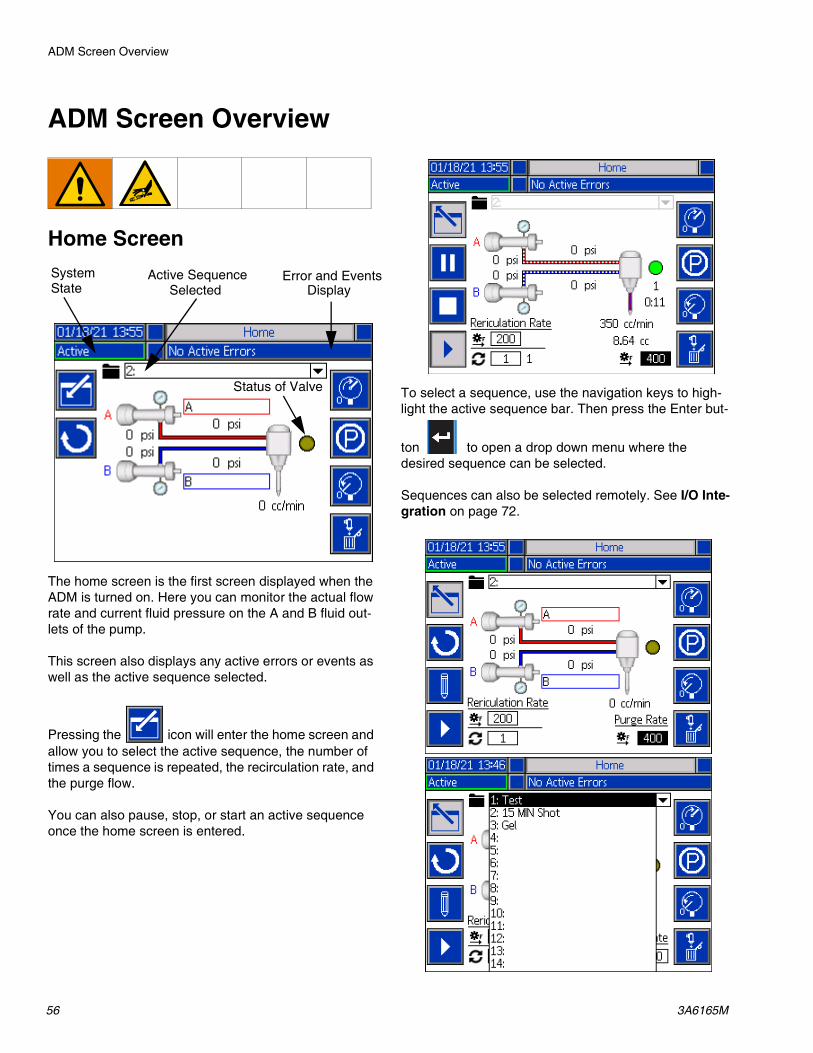
ADM Screen Overview
56 3A6165M
ADM Screen Overview
Home Screen
The home screen is the first screen displayed when the ADM is turned on. Here you can monitor the actual flow rate and current fluid pressure on the A and B fluid out-lets of the pump.
This screen also displays any active errors or events as well as the active sequence selected.
Pressing the icon will enter the home screen and allow you to select the active sequence, the number of times a sequence is repeated, the recirculation rate, and the purge flow.
You can also pause, stop, or start an active sequence once the home screen is entered.
To select a sequence, use the navigation keys to high-light the active sequence bar. Then press the Enter but-
ton to open a drop down menu where the desired sequence can be selected.
Sequences can also be selected remotely. See I/O Inte-gration on page 72.
Error and EventsDisplay
Active Sequence
Status of Valve
SystemState Selected

ADM Screen Overview
3A6165M 57
Along the right side of the home screen, there are icons that will allow the user to prime, park, de-pressurize, and purge the unit.
NOTE: The system must be active to access these icons. The only icon that can be selected when the sys-tem is inactive is the de-pressurize icon.
Prime: When pressed, the prime icon will prime the unit. The sequence that will run when the prime icon is pressed depends on the pressure preset set by the user. See Setup Screen 2 on page 63 for information on setting the Pressure Preset.
Park: When pressed, the park icon will park the pumps.
De-Pressurize: When pressed, the de-pressurize icon
will open the dispense valve, which will relieve pressure in the pump lines.
Purge: When pressed, the purge icon will purge material from the pumps. To stop purging material from
the pumps, press the purge icon again.
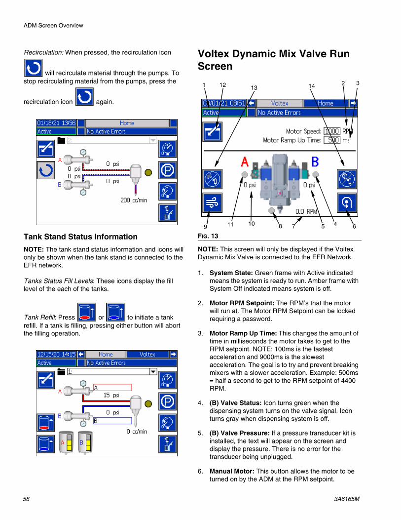
ADM Screen Overview
58 3A6165M
Recirculation: When pressed, the recirculation icon
will recirculate material through the pumps. To stop recirculating material from the pumps, press the
recirculation icon again.
Tank Stand Status InformationNOTE: The tank stand status information and icons will only be shown when the tank stand is connected to the EFR network.
Tanks Status Fill Levels: These icons display the fill level of the each of the tanks.
Tank Refill: Press or to initiate a tank refill. If a tank is filling, pressing either button will abort the filling operation.
Voltex Dynamic Mix Valve Run Screen
NOTE: This screen will only be displayed if the Voltex Dynamic Mix Valve is connected to the EFR Network.
1. System State: Green frame with Active indicated means the system is ready to run. Amber frame with System Off indicated means system is off.
2. Motor RPM Setpoint: The RPM’s that the motor will run at. The Motor RPM Setpoint can be locked requiring a password.
3. Motor Ramp Up Time: This changes the amount of time in milliseconds the motor takes to get to the RPM setpoint. NOTE: 100ms is the fastest acceleration and 9000ms is the slowest acceleration. The goal is to try and prevent breaking mixers with a slower acceleration. Example: 500ms = half a second to get to the RPM setpoint of 4400 RPM.
4. (B) Valve Status: Icon turns green when the dispensing system turns on the valve signal. Icon turns gray when dispensing system is off.
5. (B) Valve Pressure: If a pressure transducer kit is installed, the text will appear on the screen and display the pressure. There is no error for the transducer being unplugged.
6. Manual Motor: This button allows the motor to be turned on by the ADM at the RPM setpoint.
FIG. 13
1 12
11 109
2 3
45 678
13 14
ADM Screen Overview
3A6165M 59
7. Motor Actual RPM: Shows what speed the motor is at during the ramp period. It is not direct feedback from the motor.
8. Air nucleation valve indicator: Icon turns green if air nucleation is enabled and the valve is open. Icon turns gray when it is off.
9. Air Purge button: Will open the air nucleation valve indefinitely to blow out the material in the mixer.
10. (A) Valve Pressure: If a pressure transducer kit is installed, the text will appear on the screen and display the pressure. There is no error for the transducer being unplugged.
11. (A) Valve Status: Turns on when the dispensing system turns on the valve signal.
12. Edit Mode: Select to enter or exit the editing mode for the screen. Icon is gray when in edit mode and blue when off.
13. Air Nucleation Disable for Dispensing: Press this button to stop the air nucleation from running while dispensing. The icon turns grey to signal that the air nucleation has been disabled for dispensing. To re-enable the air nucleation for dispensing, press the button again. Every time a dispense occurs with the air nucleation disabled, an ECAA error will be placed into the events. See Troubleshooting on page 32 for more information on this error code.
14. Motor Spinning Disable for Dispensing: Press this button to stop the motor from spinning while dispensing. The icon turns grey to signal that the motor has been disabled for dispensing. To re-enable the motor for dispensing, press the button again. Every time a dispense occurs with the motor disabled, an ECMA error will be placed into the events. See Troubleshooting on page 32 for more information on this error code.

ADM Screen Overview
60 3A6165M
Index Menu
From the home screen, press the button to access the index. This screen provides access to Sequence Definition, Setup, Advanced, Maintenance, Shot Log, Events, Errors, and Integration screens.
Sequence Definition Screen 1
This screen allows users to create and edit sequences. From here, users are able to edit the flow rate, shot size and calibration of individual shot sizes in a selected sequence. There are four options available for the shot size, including operator mode, volume, mass/weight and seconds.
NOTE: If the user selects seconds for the shot size, cal-ibration will no longer be an option for the selected shot size.
NOTE: If the user selects operator mode for the shot size, the EFR will only dispense at the desired flow rate as long as an external trigger source or foot switch is active for that particular shot of the sequence.
NOTE: If the flow rate is set to zero, the EFR will wait for the specified amount of time before performing the next shot size.
New shot sizes can be added to a sequence by pressing
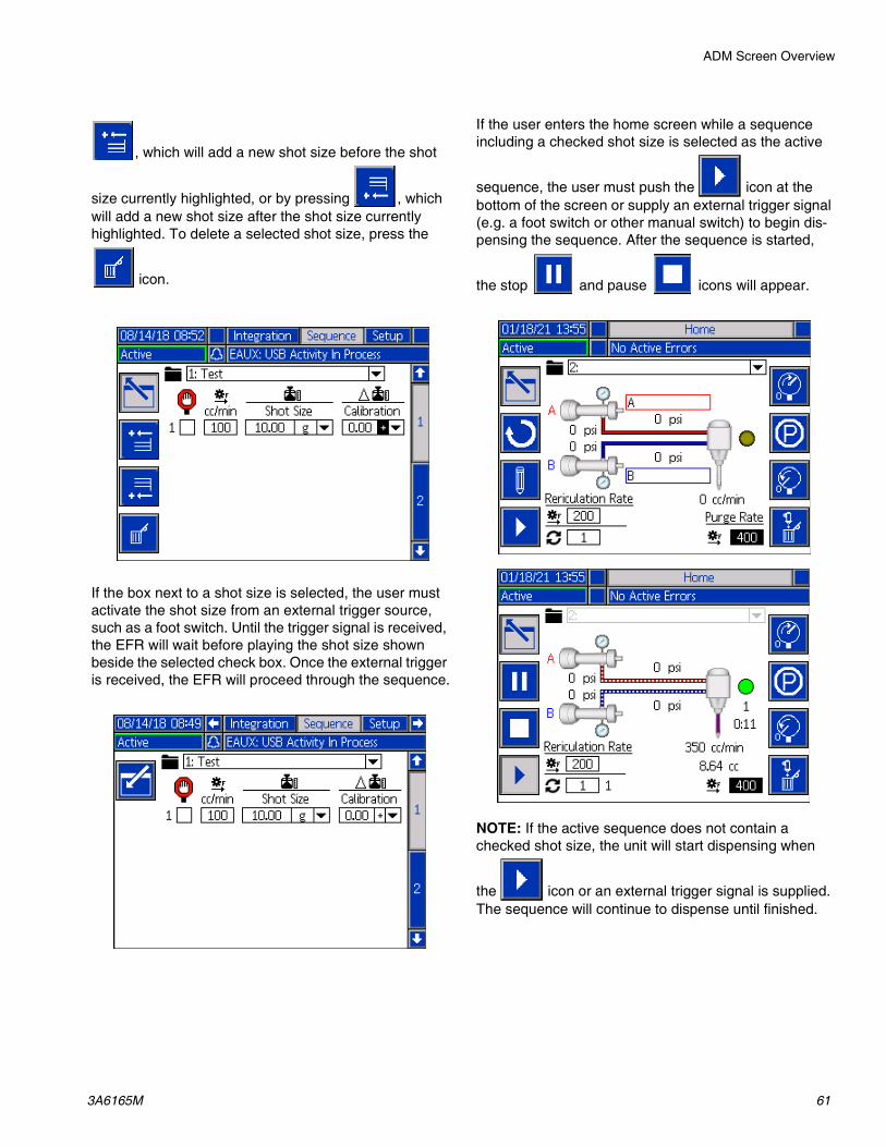
ADM Screen Overview
3A6165M 61
, which will add a new shot size before the shot
size currently highlighted, or by pressing , which will add a new shot size after the shot size currently highlighted. To delete a selected shot size, press the
icon.
If the box next to a shot size is selected, the user must activate the shot size from an external trigger source, such as a foot switch. Until the trigger signal is received, the EFR will wait before playing the shot size shown beside the selected check box. Once the external trigger is received, the EFR will proceed through the sequence.
If the user enters the home screen while a sequence including a checked shot size is selected as the active
sequence, the user must push the icon at the bottom of the screen or supply an external trigger signal (e.g. a foot switch or other manual switch) to begin dis-pensing the sequence. After the sequence is started,
the stop and pause icons will appear.
NOTE: If the active sequence does not contain a checked shot size, the unit will start dispensing when
the icon or an external trigger signal is supplied. The sequence will continue to dispense until finished.

ADM Screen Overview
62 3A6165M
Sequence Delays Screen 2
This screen allows the user to define delay settings for a sequence.
NOTE: On/Off delay for both the dispense valve and motor is not allowed.
NOTE: If multiple steps are defined in a sequence, the delays will be the same only if the step is triggered from an external source.
NOTE: If the Voltex Dynamic Mix Valve is connected, the sequence delays are disabled and the screen is hid-den.
Sequence Definition Screen 3
This screen allows the user to copy, delete, and name selected sequences. Use the arrow keys to select a sequence from the list. The sequence selected will be highlighted in green, as shown below.
NOTE: The sequence selected in this screen will also be shown in the Sequence Definition Screen 1, where it can be edited. See Sequence Definition Screen 1 on page 60.
To name a sequence, press the icon when the desired sequence is selected. A new screen, shown below, will appear and allow the user to edit the name of the selected sequence. Use the arrow keys to select the
desired letter and press to accept the letter.

ADM Screen Overview
3A6165M 63
Setup Screen 1
This screen allows the user to change the dispense mode, rate units, pressure units, pressure imbalance alarm, and the pump line, size and specific gravity of the A and B pumps.
Dispense Mode: The dispense mode can be set to either volume or weight. If the dispense mode is set to weight, the flow rate will be displayed in g/min, and if it is set to volume, the flow rate will be displayed in cc/min.
Rate Units: The rate units can be set to minute, second, or hour.
Pressure Units: The pressure units can be set to either psi or bar.
Pressure Imbalance Alarm: When checked, the pres-sure imbalance alarm will watch the pressure for both A and B pumps. If the pressure difference between pumps is greater then the pressure defined in the alarm box, an alarm will be triggered.
Pump Line: The pump line can currently only be set to Z-Series.
Size: The user can enter the size of the A and B pumps on the unit here.
Specific Gravity: The user can enter the specific gravity of the material being used here.
Setup Screen 2
This screen allows the user to set a Gel Timer and Pres-sure Preset.
Gel Timer: When enabled, the gel timer prevents mate-rial from curing in the mixer. The user can select a sequence to run, as well as the amount of idle time the machine can wait between dispenses. If the system does not dispense again before the set time runs out, the gel timer will dispense the preset sequence.
Enable: Check this box to enable the gel timer.
Idle Period: This is the amount of time the unit will remain idle before beginning to dispense.
Alarm: This is the amount of time the EFR will wait after the idle period has been reached. This allows time for the robot to move into the purge location.
Repeat Until: The selected sequence will be repeated until the specified amount of material has been purged.
Pressure Preset: The pressure preset allows the user to select the sequence that will run when the prime icon
is pressed on the home screen. The user can either select the Active Sequence, which is shown on the home screen, or one of the other sequences listed in the drop down menu for the pressure preset. Running the pressure preset allows the EFR to learn the running pressure and prime the system.
Repeat Until: The selected sequence will be repeated until the specified amount of material is reached during priming.

ADM Screen Overview
64 3A6165M
Setup Screen 3
This screen allows the user to define the recirculation mode that the EFR will operate in.
Recirculation Mode: There are three options available for Recirculation Mode (Timer, Manual, Disable).
• Timer: The EFR will recirculate for a specified amount of time after a previously set amount of time has expired.
NOTE: To start the timer feature in Recirculation Mode,
the recirculation icon must be pressed on the home screen. After the icon is pressed, the EFR will begin recirculating the pumps and count down the Recirculation On timer. Once the timer has expired, the EFR will count down the Recirculation Off timer before repeating the process. See page 64 for more informa-tion on the Recirculation On and Off timers.
NOTE: When a dispense is requested, or another fea-ture is enabled, the recirculation timer will be stopped.
• Manual: The EFR will begin recirculating when the
recirculation icon is pressed on the run screen. The EFR will continue recirculating until the
recirculation icon is pressed again.
• Disable: The EFR will disable all recirculation fea-tures.
Recirculation Rate: This is the rate at which the system will recirculate material. When the Recirculation Mode is set to Disable, this option will be grayed out.
Recirculation On: This is the amount of time the system will continue to recirculate if the Recirculation Mode is set to Timer.
Recirculation Off: This is the amount of time the system will wait before starting the Recirculation On timer when the Recirculation Mode is set to Timer.
Park Using Recirculation Valves: If checked, the park feature will park the pumps using the recirculation valves instead of the dispense valves.
Park After Recirculation is Completed: If checked, along with Park Using Recirculation Valves, the system will automatically start parking the system after recirculation is completed. This can be canceled at any time while parking the pumps.
NOTE: The Recirculation On and Recirculation Off time can only be set if the Recirculation Mode is set to Timer. Otherwise, Recirculation On and Recirculation Off will be grayed out.
NOTE: If Disable is selected for the Recirculation Mode, all other options on the screen will be grayed out.
Setup Screen 4
This screen allows the user to monitor inlet and outlet pressures of the EFR during a dispense. The user can specify a minimum and maximum allowable value for A and B for both inlet and outlet pressures. The user can also specify the level of alerts for each individual pres-sure limit. The alert options include Disabled, Deviation, and Alarm.
Disabled: No pressure monitoring will occur.
Deviation: The user will be notified if the pressure goes below the minimum or above the maximum, but further dispensing will be allowed to occur.
Alarm: If the pressure goes below the minimum or above the maximum, the current dispense will stop and further dispensing will not be allowed until the alarm is acknowledged.
NOTE: Inlet pressure monitoring is only available on systems with the Pressure Transducer Kit (25B128 or 25U084) installed. Setup screen 3 will only display outlet monitoring if the kit is not installed.
NOTE: Check the kit number displayed on the screen to visually confirm what inlet pressure kit is installed with the EFR.

ADM Screen Overview
3A6165M 65
Setup Screen 5
NOTE: This screen will only be displayed if the Voltex Dynamic Mix Valve is connected to the EFR network.
NOTE: To choose any of the following menu selections,
use the navigation buttons (BH) then press the enter key (BF) to activate that selection. Reference Advanced Display Module (ADM) on page 11 for screen ADM menu.
Edit Mode: Select to enter or exit the editing mode for the screen. Icon is gray when in edit mode and blue when off.
Air Nucleation: This will enable the air nucleation sole-noid valve. This cycles while dispensing to dose air into the mixed material.
Delay Time: Amount of time before the air nucleation valve toggles between the on time and off time.
On Time: Amount of time the air nucleation valve stays on before toggling off.
Off Time: Amount of time the air nucleation valve stays off before toggling back on.
Motor Speed: The RPM’s that the motor will run at. The Motor RPM Setpoint can be locked out using a pass-word.
Motor Ramp Up Time: This changes the amount of time in milliseconds the motor takes to get to the RPM set-point.
EFR Dispense Wait: This will cause the EFR to wait until the Voltex Dynamic Mix Valve motor is up to speed before dispensing.
NOTE: 100ms is the fastest acceleration and 9000ms is the slowest acceleration. The goal is to try and prevent breaking mixers with a slower acceleration. Example: 500ms = half a second to get to the RPM setpoint of 4400RPM.
Pressure Calibration:
NOTE: The pump transducer offset and the valve trans-ducer offset are shown in the Calibrate section.
a. Relieve pressure in the system using valve depressurization. See Pressure Relief Procedure on page 27.
b. Press the edit mode key .
c. Press the soft key to automatically reset the offsets to zero. You can also manually change the values and select minus or plus from the drop down menus as appropriate for the calibration.
d. Press the soft key to save your changes and exit editing mode.

ADM Screen Overview
66 3A6165M
Setup Screen 6
NOTE: This screen will only be displayed if a tank stand is connected to the EFR network.
This screen allows the user to specify the operating parameters for off-board, integrated tanks and indicate which positions have level sensors installed. See the the appropriate Tank Stand manual for information about installing level sensors. See Related Manuals on page 2. The user may select from the following refill settings: Disabled, Monitor, Manual, Auto Top-Off.
The following describes the system operation when each tank mode is selected.
Disabled:
• Disable tank operation.
Monitor:
• The top sensor generates a high level deviation and the bottom sensor generates a low level deviation.
• Refill is not supported, and no button is provided on the run screens to initiate refill.
• Errors will clear when the corresponding condition clears.
Manual:
• The low level sensor will generate a low level devia-tion.
• An icon is shown on the Run screens to initiate a manual refill operation at any time.
• Manual refill will continue until either the high level sensor sees material, the user abouts the refill via the refill button on the run screens, or the refill time-out expires.
• The low level alarm will clear when the condition clears.
Auto Top-Off:
• The low level sensor will generate a low level devia-tion.
• When the high level sensor does not see material, automatic refill will begin and continue until either the high level sensor sees material or until the refill time-out expires.
• The low level deviation will clear when the condition clears.
• An icon is shown on the Run screens to initiate an automatic refill operation at any time.
• This icon can also be used to abort a refill operation.
Refill Setting: If a refill setting other than Disabled is selected, the user must set at least two level sensor locations as installed by checking the check box on the screen. If all three locations are set to installed, the sys-tem will default to the Auto-Top Off refill setting and operate as follows:
• The low level sensor will generate a low level devia-tion.
• The high level sensor will generate a high level devi-ation and abort any automatic refill operation.
• When the middle sensor is not satisfied, automatic refill will begin and will run until either the middle sensor is satisfied, the high level sensor generates a deviation (if the middle sensor fails), or the refill time-out expires.
• The low level deviation and the high level deviation will clear when the condition clears.
• An icon is shown on the Run screens to initiate an automatic refill operation at any time. This icon can also be used to abort a refill operation.
Refill Timeout: The refill timeout setting may be set by the user as a means to abort the refill in the case of a high level sensor failure. When an automatic refill begins, the time-out counter will begin to count down. If the timer expires before the high level sensor is satis-fied, the refill will abort.

ADM Screen Overview
3A6165M 67
Advanced Screen 1
This screen allows the user to change the language, date, and time shown on the ADM. The user can also set up a password and change the screen saver here.
Advanced Screen 2
This screen allows the user to view and upgrade soft-
ware installed on the system. Clicking the icon will open a new screen that shows what software is cur-rently installed.
Advanced Screen 3
This screen allows the user to change the material names and ratio.

ADM Screen Overview
68 3A6165M
Maintenance Screen 1
This screen keeps track of the cycles of the A and B pump, both current and lifetime, as well as the number of times the dispense valve has opened and closed. The user can also jog the pumps from the maintenance screen.
The user can clear the current cycles for the pumps or the dispense valve by highlighting the desired pump (A
or B) or dispense valve and pressing the icon.
The user can press the arrows at the bottom of the
screen to jog the pumps forward or backward
.
The icon is used for the calibration of a new motor control board in the electric driver, and should only be pressed when the motor board is replaced or when error W5NX is active.
This screen also allows the user to generate an exces-sive Pump or Dispense Valve cycles advisory, if the cor-responding Pump or Valve cycles exceeds the number entered in the second column limit field. If a non-zero number is entered in that field, and the corresponding pump or valve cycles exceeds that value, the EFR will generate and log an advisory informing the user of the condition. To remove the advisory, either enter 0 in the Current counter, raise the Limit value, or enter zero for the limit value.
Maintenance Screen 2
This screen allows users to see the line voltage of the incoming AC power, the motor temperature, the per-centage of torque on the motor, and the position of the pumps.
The arrow located to the right of the pumps position indi-cates the direction the pumps are moving. When the arrow is green, the pumps are moving, and when the arrow is red, the system is going through a changeover.
A green arrow pointing up means the pump is moving towards the driver housing, and a green arrow pointing down means the pump is moving towards the pumps.
A red arrow pointing up signifies a top changeover, and a red arrow pointing down signifies a bottom change-over.

ADM Screen Overview
3A6165M 69
Shot Log
This screen shows users a list of all completed shots. Each shot entry includes a date and time stamp, the sequence selected, the amount dispensed, and that start pressures of the A and B pumps.
Events Screens
This screen shows users a list of events that have occurred in the system. Each event includes a descrip-tion and event code along with a date and time stamp. There are 20 pages, each holding 10 events. The 200 most recent events are shown.
Errors Screens
This screen shows users a list of errors that have occurred in the system. Each error entry includes a description and error code along with a date and time stamp. There are 5 pages, each holding 10 errors. The 50 most recent errors are shown.
Integration Screen 1
This screen allows the user to see when the unit is receiving inputs from a PLC, as well as when the unit is sending outputs to a PLC. Integration inputs must be enabled by checking the box for the EFR to use the sig-nal. If the check box is not checked, the EFR will ignore the signal.
For explanations of each integration pin, see I/O Inte-gration on page 72.

ADM Screen Overview
70 3A6165M
Integration Screens 2 and 3
This screen will appear when a CGM is connected.
This screen displays the setup screen for a connected CGM. See the Communications Gateway Module Instal-lation Kit Instructions-Parts manual for more informa-tion.
USB Plug-In Screen
This screen will appear when a USB device is plugged into the ADM.
Here the user can select dates to download data from the ADM to the USB device by pressing the left and right
arrow icons on either side of the screen .
Once the dates are selected, press the icon, and the download will begin. Information available to down-load onto a USB device includes shot log data, errors and events.
If the cancel icon is pressed, the USB download will be aborted.

Software Update
3A6165M 71
Software UpdateNOTE: If burning your own software token, see the ADM Token Programming manual. See Related Manuals on page 2. Otherwise, proceed to 17Y711 Software Update Procedure.
17Y711 Software Update ProcedureNOTE: A token can be found in the ADM token compart-ment.
When software is updated on the ADM the software is then automatically updated on all connected modules. A status screen is shown while software is updating to indicate progress.
1. Turn power disconnect switch (C) to the OFF position.
2. Remove ADM from bracket.
3. Remove token access panel (BK).
4. Insert and press EFR software upgrade token (TK, part no. 17Y711) firmly into slot.
NOTE: There is no preferred orientation of token.
5. Turn the power disconnect switch (C) to the ON position.
NOTE: When the ADM display turns on, you may see the following screens:
6. Remove token (TK).
7. Replace token access panel (BK).
8. Install ADM into bracket.
9. Press to continue to EFR operation screens.
BK
ADM
TK
NOTICEA status is shown while software is updating to indicate progress. To prevent corrupting the software load, do not remove token until the status screen disappears.
First:
Software is checking which modules will take the available updates.
Second:
Status of the update with approximate time until completion.
Third:
Updates are complete. Icon indicates update success/failure. See the following Icon table.
Icon Description
Update successful.
Update unsuccessful.
Update complete, no changes necessary.
Modules were updated or didn’t require an update; however, one or more modules need to be updated manually with a token.
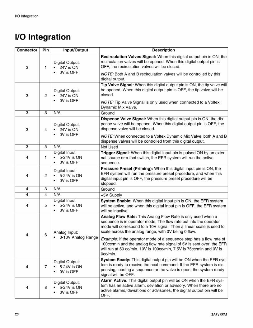
I/O Integration
72 3A6165M
I/O IntegrationConnector Pin Input/Output Description
3 1Digital Output:• 24V is ON• 0V is OFF
Recirculation Valves Signal: When this digital output pin is ON, the recirculation valves will be opened. When this digital output pin is OFF, the recirculation valves will be closed.
NOTE: Both A and B recirculation valves will be controlled by this digital output.
3 2Digital Output:• 24V is ON• 0V is OFF
Tip Valve Signal: When this digital output pin is ON, the tip valve will be opened. When this digital output pin is OFF, the tip valve will be closed.
NOTE: Tip Valve Signal is only used when connected to a Voltex Dynamic Mix Valve.
3 3 N/A Ground
3 4Digital Output:• 24V is ON• 0V is OFF
Dispense Valve Signal: When this digital output pin is ON, the dis-pense valve will be opened. When this digital output pin is OFF, the dispense valve will be closed.
NOTE: When connected to a Voltex Dynamic Mix Valve, both A and B dispense valves will be controlled from this digital output.
3 5 N/A Not Used
4 1Digital Input:• 5-24V is ON• 0V is OFF
Trigger Signal: When this digital input pin is pulsed ON by an exter-nal source or a foot switch, the EFR system will run the active sequence.
4 2Digital Input:• 5-24V is ON• 0V is OFF
Pressure Preset (Priming): When this digital input pin is ON, the EFR system will run the pressure preset procedure, and when this digital input pin is OFF, the pressure preset procedure will be stopped.
4 3 N/A Ground4 4 N/A +5V Supply
4 5Digital Input:• 5-24V is ON• 0V is OFF
System Enable: When this digital input pin is ON, the EFR system will be active, and when this digital input pin is OFF, the EFR system will be inactive.
4 6 Analog Input:• 0-10V Analog Range
Analog Flow Rate: This Analog Flow Rate is only used when a sequence is in operator mode. The flow rate put into the operator mode will correspond to a 10V signal. Then a linear scale is used to scale across the analog range, with 0V being 0 flow.
Example: If the operator mode of a sequence step has a flow rate of 100cc/min and the analog flow rate signal of 5V is sent over, the EFR will run at 50 cc/min. 10V is 100cc/min, 7.5V is 75cc/min and 0V is 0cc/min.
4 7Digital Output:• 5-24V is ON• 0V is OFF
System Ready: This digital output pin will be ON when the EFR sys-tem is ready to receive the next command. If the EFR system is dis-pensing, loading a sequence or the valve is open, the system ready signal will be OFF.
4 8Digital Output:• 5-24V is ON• 0V is OFF
Alarm Active: This digital output pin will be ON when the EFR sys-tem has an active alarm, deviation or advisory. When there are no active alarms, deviations or advisories, the digital output pin will be OFF.

I/O Integration
3A6165M 73
NOTE: The EFR software considers +5V as ON, which means the +5V supply on pin 3 of connector 4 can also be used as an external source to trigger digital input pins ON.
I/O Integration Cable ColorsThe following table shows the wire color codes for the M12, 8 pin bare leads 13.1 ft (4 m) pigtail cable (128441) supplied with the EFR for I/O integration from EFR connector 4.
Connector 3
Connector 4
Pin Color1 White2 Brown3 Green4 Yellow5 Gray6 Pink7 Blue8 Red

I/O Integration
74 3A6165M
I/O Integration DiagramsBefore any integration signals can be sent over the I/O connection(s), the integration inputs to the EFR must be enabled on Integration Screen 1, and the system must be in the active state. Once the system ready pin is ON, the EFR is ready to receive commands from the PLC.
To put the system in the active state, press the button on the ADM until the ADM LED status turns
green, and “Active” is displayed in the upper left corner of the display. The system can also be put into the active state by turning the system enable I/O pin ON.
Once the system is in the active state, dispense com-mands can be sent over the I/O pins. This can be seen in the diagrams shown below.
NOTE: A 100ms delay is suggested between each I/O signal.
When the pressure preset pin is ON and the system is in the active state, the system will start the priming feature. If the system or pressure preset pin turns OFF, the system will stop the priming feature.
Automation Inputs (EFR Outputs)
System Ready
Alarm Active
Valve Signal
Automation Outputs (EFR Inputs)
System Enable
Pressure Preset
EFR State
Priming Running
KeyEFR Priming in Process
EFR Discrete Signal Run Pressure Preset

I/O Integration
3A6165M 75
If the sequence is not in operator mode, a pulse on the trigger pin will result in the sequence being played.
Sending the sequence select bits is optional. If the sequence select bits are not sent, the EFR will use the current selected sequence.
If a shot is in operator mode throughout a sequence, the EFR will only dispense that shot if the trigger pin is ON. Once the trigger pin is OFF, the EFR will continue to the next shot in the sequence.
Sending the sequence select bits is optional. If the sequence select bits are not sent, the EFR will use the current selected sequence.
Automation Inputs (EFR Outputs)
System Ready
Alarm Active
Valve Signal
Automation Outputs (EFR Inputs)
Trigger Signal (Foot Switch)
System Enable
Sequence Select Bits (optional command)
EFR State
Sequence Running
KeyEFR Sequence is running
EFR Discrete Signal Run Sequence
Automation Inputs (EFR Outputs)
System Ready
Alarm Active
Valve Signal
Automation Outputs (EFR Inputs)
Trigger Signal (Foot Switch)
System Enable
Sequence Select Bits (optional command)
EFR State
Sequence Running
KeyEFR Sequence is running in Operator Mode
EFR Discrete Signal Run Sequence in Operator Mode
Analog Flow Rate Set Point Command can be used to modify flow rate on the fly
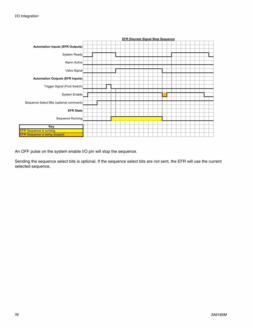
I/O Integration
76 3A6165M
An OFF pulse on the system enable I/O pin will stop the sequence.
Sending the sequence select bits is optional. If the sequence select bits are not sent, the EFR will use the current selected sequence.
Automation Inputs (EFR Outputs)
System Ready
Alarm Active
Valve Signal
Automation Outputs (EFR Inputs)
Trigger Signal (Foot Switch)
System Enable
Sequence Select Bits (optional command)
EFR State
Sequence Running
KeyEFR Sequence is runningEFR Sequence is being stopped
EFR Discrete Signal Stop Sequence

I/O Integration
3A6165M 77
Remote Sequence SelectionThe active sequence can be changed using Connector #1 (AP) on the ADM. Selection bits are pulled high by default and must be dropped low to select the desired sequence.
Foot Switch ConnectionConnect the foot switch (255244) by plugging the 5 pin female connector of cable 17Z431 to the foot switch connector. If the I/O integration cable (128441) is also desired, connect the splitter (127948) to connector 4 of the EFR, then connect the integration cable (128441) and cable 17Z431 to the splitter. If the I/O integration cable is not desired, connect cable 17Z431 to connector 4 of the EFR.
Sequence Number Selected
Sequence Selection
BIT0 (Conn. #1,
Pin #1)
Sequence Selection
BIT1 (Conn. #1,
Pin #2)
Sequence Selection
BIT2 (Conn. #1,
Pin #4)
Sequence Selection
BIT3 (Conn. #1,
Pin #5)None / Display Module
Selection
High High High High
1 Low High High High2 High Low High High3 Low Low High High4 High High Low High5 Low High Low High6 High Low Low High7 Low Low Low High8 High High High Low9 Low High High Low10 High Low High Low11 Low Low High Low12 High High Low Low13 Low High Low Low14 High Low Low Low15 Low Low Low Low
Brown
Gray
Black
Blue
White
2
3
1
5
4
SHOT SEL - BIT 0
SHOT SEL - BIT 2
SHOT SEL - BIT 3
SHOT SEL - BIT 1
COMMON
ADM Connector #1 (AP)
NOTE: The view shown looking at the pins on the endof the cable.

Wiring Diagrams
78 3A6165M
Wiring DiagramsNOTE: See the APD20 Advanced Precision Driver Instructions manual for driver internal wiring.
Power Wiring
X5H5
X4
H4
X1-X3X6-X9
H1-H3H6-H9
Customer Ground
CustomerPower In
Customer Ground
CustomerPower In

Dimensions
3A6165M 79
Dimensions
C
D
B
A
E
DimensionsA Machine Mounting Holes 21.5 in. (55 cm)
For 3/8 in. (10mm) Mounting Fasteners
B Machine Mounting Holes 21.1 in. (54 cm)
C Total Machine Height 22 in. (56 cm)
D Total Machine Length 50 in. (127cm)
E Total Machine Width 22.5 in. (57 cm)
F Mounting Hole Offset 12 in. (30 cm)
F

Technical Specifications
80 3A6165M
Technical Specifications
EFRUS Metric
Maximum fluid working pressure ‡ 3500 psi 24 MPa, 241 barMaximum fluid temperature 120°F 50°CFluid circulation ports 1/4 NPS(m)
Line voltage rating200-240V, 1ph, 50/60 Hz400-480V, 1ph, 50/60 Hz
Wetted partsStainless steel, zinc-plated carbon steel, brass, tungsten carbide, chrome, fluoroelastomer, PTFE, ultra-high molec-ular weight polyethylene, silicon nitride
Weight (not including supply pumps)240V systems 320 lbs 145 kg480V systems 401 lbs 182 kgFull load amperage240V systems 20A480V systems 10AFluid inlet pressure at inlet fitting
Pump Inlet 70 - 2000 psi 0.48 - 13.8 MPa, 4.8 - 138 bar
Fluid InletsComponent A 3/4 npt(f)Component B 3/4 npt(f)Fluid Outlets on ManifoldsComponent A 1/2 npt(f)Component B 1/2 npt(f)Notes‡ The maximum fluid working pressure for the base machine without hoses is 3500 psi (24.1 MPa,
241 bar). If hoses, valves or accessories rated at less than 3500 psi are installed, the system maxi-mum fluid working pressure becomes the rating of the hoses. The minimum pressure rating for hoses is 2000 psi. Do not install hoses with a pressure rating lower than 2000 psi.
All other brand names or marks are used for identification purposes and are trademarks of their respective owners.
PerformanceCombined Displacement
(A Pump + B Pump)Min Shot Size Min Output
FlowMax Output Flow
(20 cycles/min max)*Max Average Outlet
Pressure‡ **60 cc 0.3 cc 20 cc/min 1,200 cc/min 3,500 psi (241 bar)80 cc 0.3 cc 20 cc/min 1,600 cc/min 3,500 psi (241 bar)
100 cc 0.3 cc 20 cc/min 2,000 cc/min 3,500 psi (241 bar)120 cc 0.3 cc 20 cc/min 2,400 cc/min 3,500 psi (241 bar)140 cc 0.3 cc 20 cc/min 2,800 cc/min 3,400 psi (235 bar)160 cc 0.3 cc 20 cc/min 3,200 cc/min 3,000 psi (207 bar)
* Flow may be limited by the amount of pressure generated when using thick materials or with high restriction.
** High inlet pressures reduce this value, subtract 2x inlet pressure.

Technical Specifications
3A6165M 81
California Proposition 65CALIFORNIA RESIDENTS
WARNING: Cancer and reproductive harm – www.P65warnings.ca.gov.

All written and visual data contained in this document reflects the latest product information available at the time of publication. Graco reserves the right to make changes at any time without notice.
Original instructions. This manual contains English. MM 3A6165Graco Headquarters: Minneapolis
International Offices: Belgium, China, Japan, Korea
GRACO INC. AND SUBSIDIARIES • P.O. BOX 1441 • MINNEAPOLIS MN 55440-1441 • USACopyright 2018, Graco Inc. All Graco manufacturing locations are registered to ISO 9001.
www.graco.comRevision M, August 2021
Graco Standard WarrantyGraco warrants all equipment referenced in this document which is manufactured by Graco and bearing its name to be free from defects in material and workmanship on the date of sale to the original purchaser for use. With the exception of any special, extended, or limited warranty published by Graco, Graco will, for a period of twelve months from the date of sale, repair or replace any part of the equipment determined by Graco to be defective. This warranty applies only when the equipment is installed, operated and maintained in accordance with Graco’s written recommendations.
This warranty does not cover, and Graco shall not be liable for general wear and tear, or any malfunction, damage or wear caused by faulty installation, misapplication, abrasion, corrosion, inadequate or improper maintenance, negligence, accident, tampering, or substitution of non-Graco component parts. Nor shall Graco be liable for malfunction, damage or wear caused by the incompatibility of Graco equipment with structures, accessories, equipment or materials not supplied by Graco, or the improper design, manufacture, installation, operation or maintenance of structures, accessories, equipment or materials not supplied by Graco.
This warranty is conditioned upon the prepaid return of the equipment claimed to be defective to an authorized Graco distributor for verification of the claimed defect. If the claimed defect is verified, Graco will repair or replace free of charge any defective parts. The equipment will be returned to the original purchaser transportation prepaid. If inspection of the equipment does not disclose any defect in material or workmanship, repairs will be made at a reasonable charge, which charges may include the costs of parts, labor, and transportation.
THIS WARRANTY IS EXCLUSIVE, AND IS IN LIEU OF ANY OTHER WARRANTIES, EXPRESS OR IMPLIED, INCLUDING BUT NOT LIMITED TO WARRANTY OF MERCHANTABILITY OR WARRANTY OF FITNESS FOR A PARTICULAR PURPOSE.
Graco’s sole obligation and buyer’s sole remedy for any breach of warranty shall be as set forth above. The buyer agrees that no other remedy (including, but not limited to, incidental or consequential damages for lost profits, lost sales, injury to person or property, or any other incidental or consequential loss) shall be available. Any action for breach of warranty must be brought within two (2) years of the date of sale.
GRACO MAKES NO WARRANTY, AND DISCLAIMS ALL IMPLIED WARRANTIES OF MERCHANTABILITY AND FITNESS FOR A PARTICULAR PURPOSE, IN CONNECTION WITH ACCESSORIES, EQUIPMENT, MATERIALS OR COMPONENTS SOLD BUT NOT MANUFACTURED BY GRACO. These items sold, but not manufactured by Graco (such as electric motors, switches, hose, etc.), are subject to the warranty, if any, of their manufacturer. Graco will provide purchaser with reasonable assistance in making any claim for breach of these warranties.
In no event will Graco be liable for indirect, incidental, special or consequential damages resulting from Graco supplying equipment hereunder, or the furnishing, performance, or use of any products or other goods sold hereto, whether due to a breach of contract, breach of warranty, the negligence of Graco, or otherwise.
FOR GRACO CANADA CUSTOMERSThe Parties acknowledge that they have required that the present document, as well as all documents, notices and legal proceedings entered into, given or instituted pursuant hereto or relating directly or indirectly hereto, be drawn up in English. Les parties reconnaissent avoir convenu que la rédaction du présente document sera en Anglais, ainsi que tous documents, avis et procédures judiciaires exécutés, donnés ou intentés, à la suite de ou en rapport, directement ou indirectement, avec les procédures concernées.
Graco InformationSealant and Adhesive Dispensing EquipmentFor the latest information about Graco products, visit www.graco.com.For patent information, see www.graco.com/patents.TO PLACE AN ORDER, contact your Graco distributor, go to www.graco.com, or call to identify the nearest distributor.
If calling from the USA: 1-800-746-1334
If calling from outside the USA: 0-1-330-966-3000