for the following information ref. file no.: c1m1308225 - asus
TRANSCRIPT
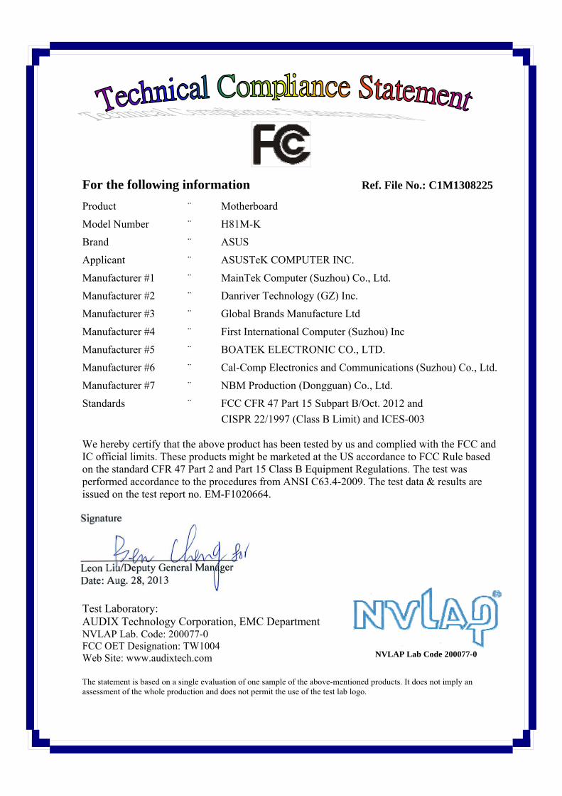
For the following information Ref. File No.: C1M1308225
Product : Motherboard
Model Number : H81M-K
Brand : ASUS
Applicant : ASUSTeK COMPUTER INC.
Manufacturer #1 : MainTek Computer (Suzhou) Co., Ltd.
Manufacturer #2 : Danriver Technology (GZ) Inc.
Manufacturer #3 : Global Brands Manufacture Ltd
Manufacturer #4 : First International Computer (Suzhou) Inc
Manufacturer #5 : BOATEK ELECTRONIC CO., LTD.
Manufacturer #6 : Cal-Comp Electronics and Communications (Suzhou) Co., Ltd.
Manufacturer #7 : NBM Production (Dongguan) Co., Ltd.
Standards : FCC CFR 47 Part 15 Subpart B/Oct. 2012 and CISPR 22/1997 (Class B Limit) and ICES-003 We hereby certify that the above product has been tested by us and complied with the FCC and IC official limits. These products might be marketed at the US accordance to FCC Rule based on the standard CFR 47 Part 2 and Part 15 Class B Equipment Regulations. The test was performed accordance to the procedures from ANSI C63.4-2009. The test data & results are issued on the test report no. EM-F1020664. Signature _____________________________ Leon Liu/Deputy General Manager Date: Aug. 28, 2013 Test Laboratory: AUDIX Technology Corporation, EMC Department NVLAP Lab. Code: 200077-0 FCC OET Designation: TW1004 Web Site: www.audixtech.com The statement is based on a single evaluation of one sample of the above-mentioned products. It does not imply an assessment of the whole production and does not permit the use of the test lab logo.
NVLAP Lab Code 200077-0

Page 1 of 36
AUDIX Technology Corporation Report No.: EM-F1020664
TEST REPORT FOR FCC DoC and INDUSTRY CANADA ASUSTeK COMPUTER INC.
Motherboard Model No.: H81M-K
Brand: ASUS Prepared for : ASUSTeK COMPUTER INC.
4F, No.150, Li-Te Rd., Peitou, Taipei, Taiwan
Prepared By : AUDIX Technology Corporation EMC Department
No. 53-11, Dingfu, Linkou Dist., New Taipei City 244, Taiwan Tel : (02) 2609-9301, 2609-2133 Fax : (02) 2609-9303
File Number : C1M1308225 (ACW Ref. No. ACWE-G1308020)
Report Number : EM-F1020664 Date of Test : Aug. 23 ~ 28, 2013 Date of Report : Aug. 28, 2013
Page 2 of 36
AUDIX Technology Corporation Report No.: EM-F1020664
TABLE OF CONTENTS
Description Page
TEST REPORT FOR COMPLIANCE DECLARATION ....................................................................3 1. GENERAL INFORMATION..........................................................................................................4
1.1.Description of Device (EUT).....................................................................................................................4 1.2.Tested Supporting System Details.............................................................................................................7 1.3.Description of Test Facility .....................................................................................................................11 1.4.Measurement Uncertainty........................................................................................................................11
2. POWERLINE CONDUCTED EMISSION MEASUREMENT................................................12 2.1.Test Equipment........................................................................................................................................12 2.2.Block Diagram of Test Setup ..................................................................................................................12 2.3.Powerline Conducted Emission Limit (FCC§15.107/ICES-003, Class B)..............................................12 2.4.Operating Condition of EUT ...................................................................................................................13 2.5.Test Procedure .........................................................................................................................................13 2.6.Powerline Conducted Emission Measurement Results ...........................................................................14
3. RADIATED EMISSION MEASUREMENT...............................................................................17 3.1.Test Equipment........................................................................................................................................17 3.2.Block Diagram of Test Setup ..................................................................................................................17 3.3.Radiation Emission Limit (FCC§15.109/CISPR 22/ICES-003, Class B) ...............................................19 3.4.Operating Condition of EUT ...................................................................................................................19 3.5.Test Procedure .........................................................................................................................................19 3.6.Radiated Emission Measurement Results................................................................................................21
4. DEVIATION TO TEST SPECIFICATIONS ..............................................................................30 5. PHOTOGRAPHS...........................................................................................................................31
5.1.Photos of Powerline Conducted Emission Measurement ........................................................................31 5.2.Photos of Radiated Emission Measurement at Open Area Test Site (30-1000MHz)..............................32 5.3.Photos of Radiated Emission Measurement at Semi-Anechoic Chamber (Above 1GHz) ......................34 5.4.Partner System.........................................................................................................................................36
APPENDIX I (Photos of EUT)

Page 3 of 36
AUDIX Technology Corporation Report No.: EM-F1020664
TEST REPORT FOR COMPLIANCE DECLARATION
Applicant : ASUSTeK COMPUTER INC. Manufacturer #1 : MainTek Computer (Suzhou) Co., Ltd. Manufacturer #2 : Danriver Technology (GZ) Inc. Manufacturer #3 : Global Brands Manufacture Ltd Manufacturer #4 : First International Computer (Suzhou) Inc Manufacturer #5 : BOATEK ELECTRONIC CO., LTD. Manufacturer #6 : Cal-Comp Electronics and Communications (Suzhou) Co., Ltd. Manufacturer #7 : NBM Production (Dongguan) Co., Ltd. EUT Description : Motherboard
(A) Model No. : H81M-K (B) Serial No. : N/A (C) Brand : ASUS (D) Power Supply : Power by PC System (E) Test Voltage : AC 120V/60Hz (via PC System)
Measurement Standard Used: FCC CFR 47 Part 15 Subpart B/Oct. 2012 and CISPR 22/1997 ANSI C63.4-2009 ICES-003 Issue 5 Aug. 2012
The device described above was tested by AUDIX Technology Corporation, to determine the maximum emission levels emanating from the device. The maximum emission levels were compared to the FCC Part 15 subpart B with the provisions of sections 15.107 and 15.109 and ICES-003 Class B limits both conducted and radiated emissions.
The measurement results are contained in this test report and AUDIX Technology Corporation is assumed full responsibility for the accuracy and completeness of these measurements. Also, this report shows that the EUT to be technically compliant with the FCC and IC official limits.
This report applies to above tested sample only and which shall not be reproduced in part without written approval of AUDIX Technology Corporation.
The report must not be used by the client to claim product certification, approval, or endorsement by NVLAP, NIST, or any agency of the Federal Government. Date of Test : Aug. 23 ~ 28, 2013 Date of Report : Aug. 28, 2013
Producer :
(Kitty Ni/Administrator) Signatory :
(Leon Liu/Deputy General Manager)
Name of the Representative of the Responsible Party :
Signature :
Page 4 of 36
AUDIX Technology Corporation Report No.: EM-F1020664
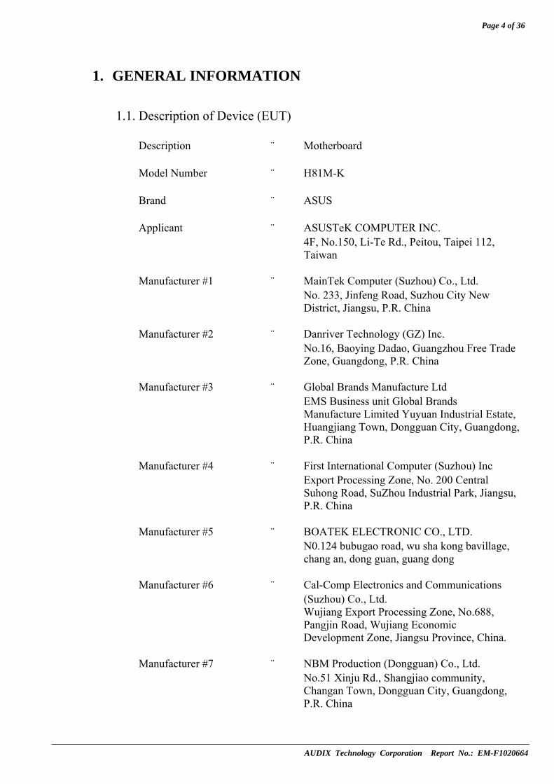
1. GENERAL INFORMATION
1.1. Description of Device (EUT) Description : Motherboard Model Number : H81M-K Brand : ASUS Applicant : ASUSTeK COMPUTER INC. 4F, No.150, Li-Te Rd., Peitou, Taipei 112,
Taiwan Manufacturer #1 : MainTek Computer (Suzhou) Co., Ltd. No. 233, Jinfeng Road, Suzhou City New
District, Jiangsu, P.R. China Manufacturer #2 : Danriver Technology (GZ) Inc. No.16, Baoying Dadao, Guangzhou Free Trade
Zone, Guangdong, P.R. China Manufacturer #3 : Global Brands Manufacture Ltd EMS Business unit Global Brands
Manufacture Limited Yuyuan Industrial Estate, Huangjiang Town, Dongguan City, Guangdong, P.R. China
Manufacturer #4 : First International Computer (Suzhou) Inc Export Processing Zone, No. 200 Central
Suhong Road, SuZhou Industrial Park, Jiangsu, P.R. China
Manufacturer #5 : BOATEK ELECTRONIC CO., LTD. N0.124 bubugao road, wu sha kong bavillage,
chang an, dong guan, guang dong Manufacturer #6 : Cal-Comp Electronics and Communications
(Suzhou) Co., Ltd. Wujiang Export Processing Zone, No.688,
Pangjin Road, Wujiang Economic Development Zone, Jiangsu Province, China.
Manufacturer #7 : NBM Production (Dongguan) Co., Ltd. No.51 Xinju Rd., Shangjiao community,
Changan Town, Dongguan City, Guangdong, P.R. China
Page 5 of 36
AUDIX Technology Corporation Report No.: EM-F1020664
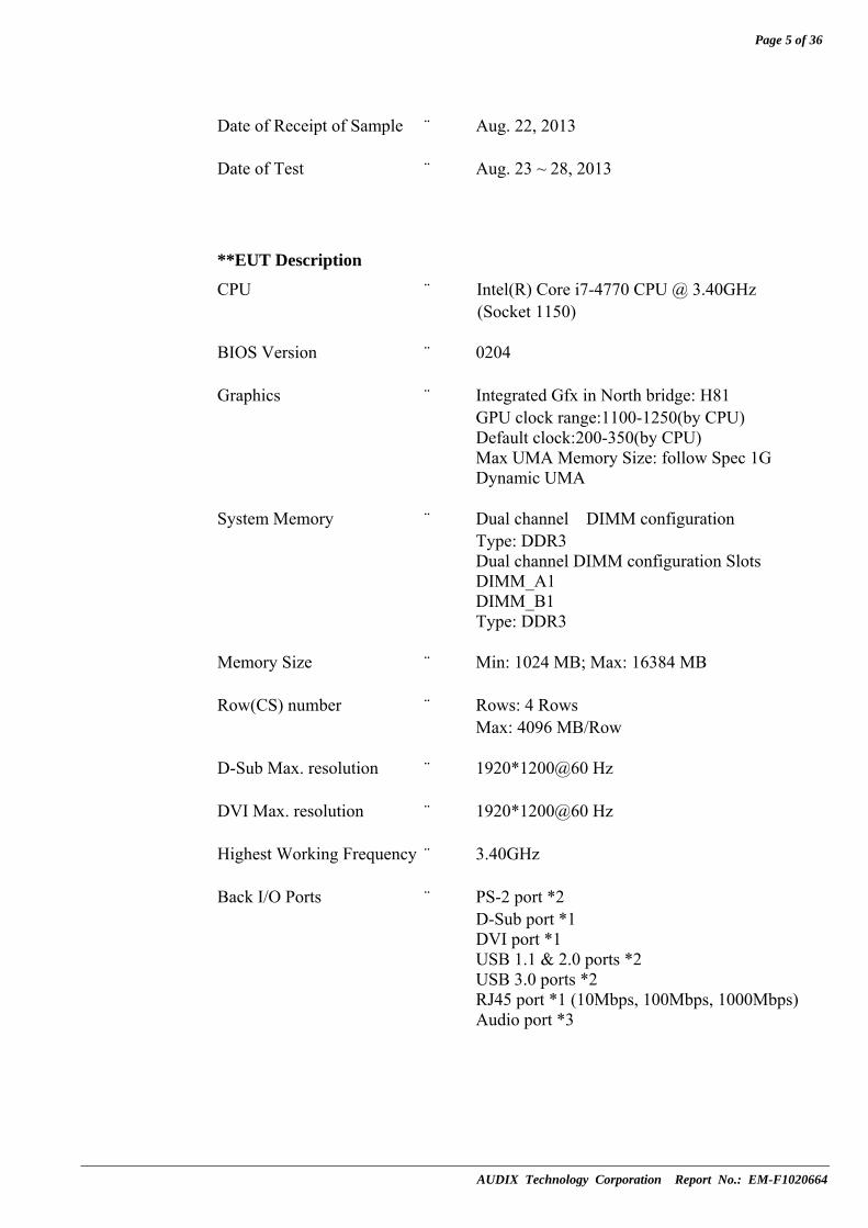
Date of Receipt of Sample : Aug. 22, 2013 Date of Test : Aug. 23 ~ 28, 2013
**EUT Description
CPU : Intel(R) Core i7-4770 CPU @ 3.40GHz (Socket 1150)
BIOS Version : 0204 Graphics : Integrated Gfx in North bridge: H81 GPU clock range:1100-1250(by CPU) Default clock:200-350(by CPU) Max UMA Memory Size: follow Spec 1G Dynamic UMA System Memory : Dual channel DIMM configuration Type: DDR3 Dual channel DIMM configuration Slots DIMM_A1 DIMM_B1 Type: DDR3 Memory Size : Min: 1024 MB; Max: 16384 MB Row(CS) number : Rows: 4 Rows Max: 4096 MB/Row D-Sub Max. resolution : 1920*1200@60 Hz DVI Max. resolution : 1920*1200@60 Hz Highest Working Frequency : 3.40GHz Back I/O Ports : PS-2 port *2 D-Sub port *1 DVI port *1 USB 1.1 & 2.0 ports *2 USB 3.0 ports *2 RJ45 port *1 (10Mbps, 100Mbps, 1000Mbps) Audio port *3

Page 6 of 36
AUDIX Technology Corporation Report No.: EM-F1020664
Remark: This EUT (Motherboard, within PC system) with the following test modes was pre-scanned. Finally, this report was selected the worst test mode to issue report.
The details of pre-scanned modes are as follows:
Operating of EUT VGA Interface, Resolutions and Frequencies
DVI + D-Sub, 1920*1200/60Hz DVI + D-Sub, 1600*1200/60Hz DVI + D-Sub, 1280*1024/75Hz
Full System
DVI + D-Sub, 640*480/60Hz
The worst test mode of finally reported are as follows:
Test Item Operating of EUT
VGA Interface, Resolutions and Frequencies
Powerline Conducted Emission
Measurement DVI + D-Sub, 1920*1200/60Hz
Radiated Emission Measurement
(30-1000MHz) DVI + D-Sub, 1600*1200/60Hz
Radiated Emission Measurement
(1-6GHz)
Full System
DVI + D-Sub, 1920*1200/60Hz
Page 7 of 36
AUDIX Technology Corporation Report No.: EM-F1020664
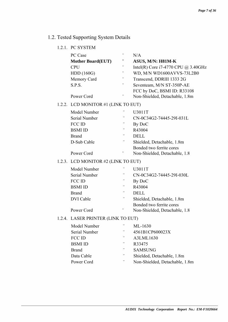
1.2. Tested Supporting System Details
1.2.1. PC SYSTEM
PC Case : N/A Mother Board(EUT) : ASUS, M/N: H81M-K CPU : Intel(R) Core i7-4770 CPU @ 3.40GHz HDD (160G) : WD, M/N WD1600AVVS-73L2B0 Memory Card : Transcend, DDRIII 1333 2G S.P.S. : Seventeam, M/N ST-350P-AE FCC by DoC, BSMI ID: R33108 Power Cord : Non-Shielded, Detachable, 1.8m
1.2.2. LCD MONITOR #1 (LINK TO EUT)
Model Number : U3011T Serial Number : CN-0C34G2-74445-29I-031L FCC ID : By DoC BSMI ID : R43004 Brand : DELL D-Sub Cable : Shielded, Detachable, 1.8m Bonded two ferrite cores Power Cord : Non-Shielded, Detachable, 1.8
1.2.3. LCD MONITOR #2 (LINK TO EUT)
Model Number : U3011T Serial Number : CN-0C34G2-74445-29I-030L FCC ID : By DoC BSMI ID : R43004 Brand : DELL DVI Cable : Shielded, Detachable, 1.8m Bonded two ferrite cores Power Cord : Non-Shielded, Detachable, 1.8
1.2.4. LASER PRINTER (LINK TO EUT)
Model Number : ML-1630 Serial Number : 4561B1CP600023X FCC ID : A3LML1630 BSMI ID : R33475 Brand : SAMSUNG Data Cable : Shielded, Detachable, 1.8m Power Cord : Non-Shielded, Detachable, 1.8m
Page 8 of 36
AUDIX Technology Corporation Report No.: EM-F1020664
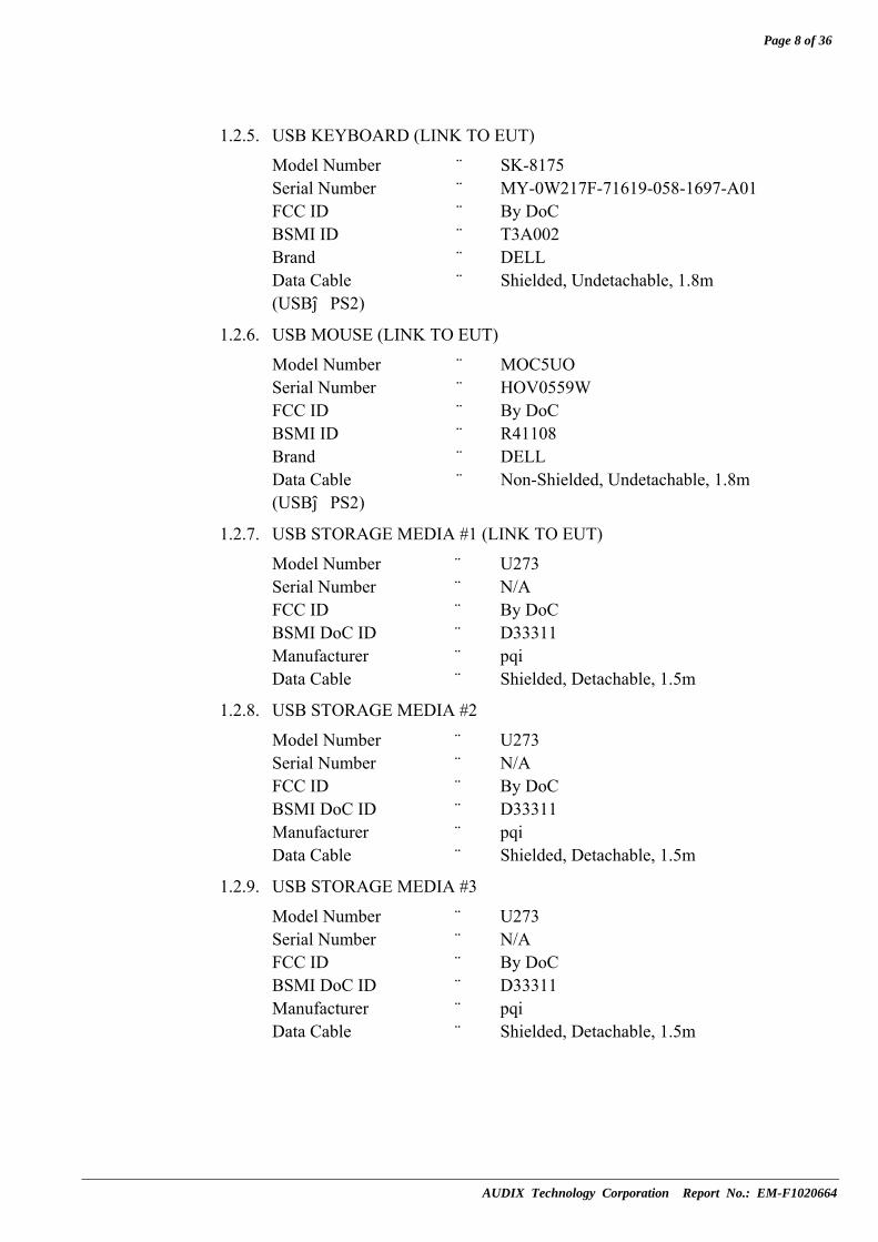
1.2.5. USB KEYBOARD (LINK TO EUT)
Model Number : SK-8175 Serial Number : MY-0W217F-71619-058-1697-A01 FCC ID : By DoC BSMI ID : T3A002 Brand : DELL Data Cable : Shielded, Undetachable, 1.8m (USB→PS2)
1.2.6. USB MOUSE (LINK TO EUT)
Model Number : MOC5UO Serial Number : HOV0559W FCC ID : By DoC BSMI ID : R41108 Brand : DELL Data Cable : Non-Shielded, Undetachable, 1.8m (USB→PS2)
1.2.7. USB STORAGE MEDIA #1 (LINK TO EUT)
Model Number : U273 Serial Number : N/A FCC ID : By DoC BSMI DoC ID : D33311 Manufacturer : pqi Data Cable : Shielded, Detachable, 1.5m
1.2.8. USB STORAGE MEDIA #2
Model Number : U273 Serial Number : N/A FCC ID : By DoC BSMI DoC ID : D33311 Manufacturer : pqi Data Cable : Shielded, Detachable, 1.5m
1.2.9. USB STORAGE MEDIA #3
Model Number : U273 Serial Number : N/A FCC ID : By DoC BSMI DoC ID : D33311 Manufacturer : pqi Data Cable : Shielded, Detachable, 1.5m

Page 9 of 36
AUDIX Technology Corporation Report No.: EM-F1020664
1.2.10. DRIVESTATION USB 3.0 HARD DRIVE #1 (LINK TO EUT)
Model Number : HD-HX1.0TU3-AP Serial Number : 15564891205996 FCC ID : By DoC BSMI DoC ID : D33093 Brand : BUFFALO USB Cable : Shielded, Detachable, 1.8m AC Adapter : M/N WA-24E12, S/N 9A9026429 Cord: Non-Shielded, Undetachable, 1.8m
1.2.11. DRIVESTATION USB 3.0 HARD DRIVE #2 (LINK TO EUT)
Model Number : HD-HX1.0TU3-AP Serial Number : 15564891206504 FCC ID : By DoC BSMI DoC ID : D33093 Brand : BUFFALO USB Cable : Shielded, Detachable, 1.8m AC Adapter : M/N WA-24E12, S/N 9A9026429 Cord: Non-Shielded, Undetachable, 1.8m
1.2.12. EARPHONE WITH MIC. & IN-LINE VOLUME CONTROL #1 (LINK TO EUT)
Model Number : HS10101 Serial Number : N/A FCC ID : By DoC BSMI ID : R34896 Manufacturer : UIO Audio Cable : Non-Shielded, Detachable,1.5m (2Pin)
1.2.13. EARPHONE WITH MIC. & IN-LINE VOLUME CONTROL #2
Model Number : HS10101 Serial Number : N/A FCC ID : By DoC BSMI ID : R34896 Manufacturer : UIO Audio Cable : Non-Shielded, Detachable,1.5m (2Pin)
1.2.14. WALKMAN (LINK TO EUT)
Model Number : RQ-P35LT-K Serial Number : HA08623 Manufacturer : Panasonic Data Cable : Non-Shielded, Detachable, 1.8m

Page 10 of 36
AUDIX Technology Corporation Report No.: EM-F1020664
** PARTNER PC SYSTEM** 1.2.15. PC SYSTEM (LINK TO EUT)
Model Number : DC8M Serial Number : 9VDSP1S FCC ID : By DoC BSMI ID : R33002 Manufacturer : DELL LAN Cable : Non-Shielded, Detachable, 10m Power Cord : Non-Shielded, Detachable, 1.8m
1.2.16. 24” LCD MONITOR
Model Number : 2408WFP Serial Number : GN-OG293H-74261-874-214S-A00 FCC ID : By DoC BSMI ID : R43002 Manufacturer : DELL Data Cable (D-Sub) : Shielded, Detachable, 1.8m Bonded two ferrite cores Power Cord : Non-Shielded, Detachable, 1.8m
1.2.17. USB KEYBOARD
Model Number : SK-8815 Serial Number : CN-ONM433-71616-7C5-0A4O FCC ID : By DoC BSMI ID : T3A002 Manufacturer : DELL USB Cable : Shielded, Undetachable, 2m Bonded a ferrite core
1.2.18. USB MOUSE
Model Number : MOC5UO Serial Number : HOV0559W FCC ID : By DoC BSMI ID : R41108 Manufacturer : DELL USB Cable : Shielded, Undetachable, 1.8m

Page 11 of 36
AUDIX Technology Corporation Report No.: EM-F1020664
1.3. Description of Test Facility Name of Firm : AUDIX Technology Corporation EMC Department
No. 53-11, Dingfu, Linkou Dist., New Taipei City 244, Taiwan
Test Site : No. 3 Shielded Room (C3/R5/Semi-AC2) No. 67-4, Dingfu, Linkou Dist., New Taipei City 244, Taiwan No. 5 Open Area Test Site No. 67-4, Dingfu, Linkou Dist., New Taipei City 244, Taiwan Federal Communication Commission Registration Number: 90992 Filing on August 03, 2010 No. 2 Semi-Anechoic Chamber No. 67-4, Dingfu, Linkou Dist., New Taipei City 244, Taiwan Federal Communication Commission Registration Number: 370172 Filing on July 20, 2010 NVLAP Lab. Code : 200077-0 TAF Accreditation No : 1724
1.4. Measurement Uncertainty
Test Item Frequency Range Uncertainty (dB)
Conduction Test 150kHz~30MHz ±1.73dB
30MHz~300MHz ±2.99dB Radiation Test
(Distance: 10m) 300MHz~1000MHz ±2.73dB
Radiation Test
(Distance: 3m) Above 1GHz ± 3.73dB
Remark : Uncertainty = kuc(y)
Page 12 of 36
AUDIX Technology Corporation Report No.: EM-F1020664
PC SYSTEM
2. POWERLINE CONDUCTED EMISSION MEASUREMENT
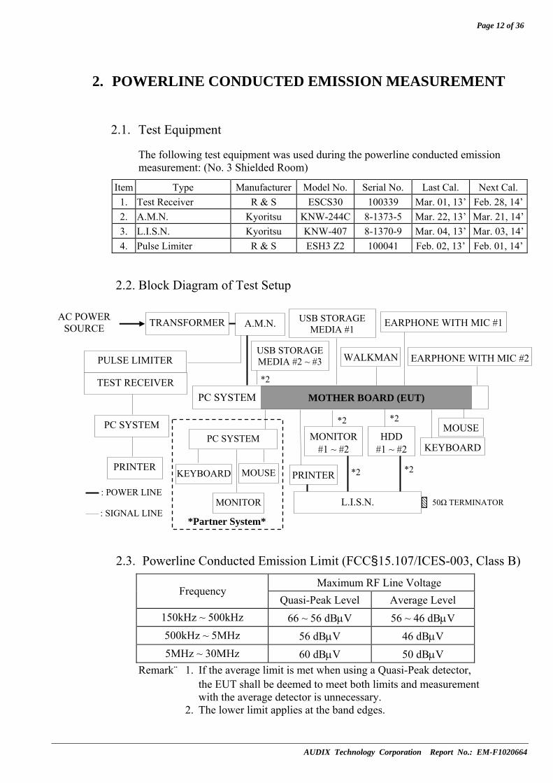
2.1. Test Equipment
The following test equipment was used during the powerline conducted emission measurement: (No. 3 Shielded Room)
Item Type Manufacturer Model No. Serial No. Last Cal. Next Cal. 1. Test Receiver R & S ESCS30 100339 Mar. 01, 13’ Feb. 28, 14’2. A.M.N. Kyoritsu KNW-244C 8-1373-5 Mar. 22, 13’ Mar. 21, 14’3. L.I.S.N. Kyoritsu KNW-407 8-1370-9 Mar. 04, 13’ Mar. 03, 14’4. Pulse Limiter R & S ESH3 Z2 100041 Feb. 02, 13’ Feb. 01, 14’
2.2. Block Diagram of Test Setup
2.3. Powerline Conducted Emission Limit (FCC§15.107/ICES-003, Class B)
Maximum RF Line Voltage Frequency
Quasi-Peak Level Average Level 150kHz ~ 500kHz 66 ~ 56 dBμV 56 ~ 46 dBμV 500kHz ~ 5MHz 56 dBμV 46 dBμV 5MHz ~ 30MHz 60 dBμV 50 dBμV
Remark: 1. If the average limit is met when using a Quasi-Peak detector, the EUT shall be deemed to meet both limits and measurement with the average detector is unnecessary.
2. The lower limit applies at the band edges.
: POWER LINE
TRANSFORMER
TEST RECEIVER
PC SYSTEM
PRINTER
50Ω TERMINATOR: SIGNAL LINE
PULSE LIMITER USB STORAGE MEDIA #2 ~ #3 WALKMAN
*Partner System*
MOUSE
MONITOR
A.M.N.
MONITOR#1 ~ #2 KEYBOARD
PRINTER
MOTHER BOARD (EUT)
L.I.S.N.
*2
EARPHONE WITH MIC #1
KEYBOARD
EARPHONE WITH MIC #2
USB STORAGE MEDIA #1
AC POWER SOURCE
PC SYSTEM MOUSE
*2
*2
HDD #1 ~ #2
*2
*2

Page 13 of 36
AUDIX Technology Corporation Report No.: EM-F1020664
2.4. Operating Condition of EUT PC system (EUT inside) Exercise Program and Condition
Operating System Windows 7
Test Program Burn In
Graphic Controller Display scrolling “H” (Arial 10) pattern with respective resolution.
Interface Controller Read/Write operation to hard disk
LAN Controller Data transfer to client
Audio Controller Run the program “Windows Media Player” and send 1kHz sound.
PS2 Port Write operation to PS/2 peripherals.
Serial Ports 1. Read/Write operation to USB storage or USB HDD.
2. Sent “H” (Arial 10) to printer
The other peripheral devices were driven and operated in turn during all testing.
2.5. Test Procedure The EUT (within PC system) was placed on table which was above the ground by 80cm and PC System’s power cord was connected to the power mains through an Artificial Mains Network (A.M.N.). The other peripheral devices power cords were connected to the power mains through a line impedance stabilization network (L.I.S.N.). This provided a 50 ohm coupling impedance for the measuring equipment. (Please refer to the block diagram of the test setup and photographs.) Both sides of A.C. line were checked for maximum conducted interference. In order to find the maximum emission, the relative positions of equipment and all of the interface cables were changed according to ANSI C63.4-2009 during conducted measurement. The bandwidth of the R&S Test Receiver ESCS 30 was set at 9kHz. The frequency range from 0.15MHz to 30MHz was pre-scanned with a peak detector. All the final readings from Test Receiver were measured with the Quasi-Peak detector and Average detector. (Remark: If the Average limit is met when using a Quasi-Peak detector, the Average detector is unnecessary)

Page 14 of 36
AUDIX Technology Corporation Report No.: EM-F1020664
2.6. Powerline Conducted Emission Measurement Results PASSED. (All emissions not reported below are too low against the prescribed limits.) The EUT (within PC system) with the following worst test mode (DVI + D-Sub, 1920*1200/60Hz) was performed during this section testing and to read Q.P. & AV. value, the test data are listed in next pages. EUT:Motherboard M/N:H81M-K Test Date:Aug. 26, 2013 Temperature:25 Humidity:55% The details are as follows:
Reference Test Data No.Mode Operating of EUT VGA Interface,
Resolutions and Frequencies Neutral Line
1. Full System DVI + D-Sub, 1920*1200/60Hz # 4 # 3

Page 15 of 36
AUDIX Technology Corporation Report No.: EM-F1020664

Page 16 of 36
AUDIX Technology Corporation Report No.: EM-F1020664

Page 17 of 36
AUDIX Technology Corporation Report No.: EM-F1020664
PC SYSTEM
3. RADIATED EMISSION MEASUREMENT
3.1. Test Equipment
The following test equipment was used during the radiated emission measurement:
3.1.1. For 30MHz-1000MHz Frequency (At No. 5 Open Area Test Site)
Item Type Manufacturer Model No. Serial No. Last Cal. Next Cal. 1. Spectrum Analyzer Anritsu E7405A MY42000134 Aug. 17, 13’ Aug. 16, 14’2. Test Receiver R & S ESCI 100555 May 9, 13’ May 08, 14’3. Pre-Amplifier HP 8447D 2944A07185 N/A N/A 4. Biconical Antenna Chase VBA6106A 1262 Mar. 02, 13’ Mar. 01, 14’5. Log Periodic Antenna Chase UPA6109 1061 Mar. 02, 13’ Mar. 01, 14’
3.1.2. For Above 1GHz Frequency (At No.2 Semi-Anechoic Chamber)
Item Type Manufacturer Model No. Serial No. Last Cal. Next Cal. 1. Spectrum Analyzer Agilent N9010A-526 MY48031076 Oct. 11, 12’ Oct. 10, 13’2. Amplifier Agilent 8449B 3008A02596 Jan. 09, 13’ Jan. 08, 14’3. Horn Antenna EMCO 3115 9609-4927 Jun. 17, 13’ Jun. 16, 14’
3.2. Block Diagram of Test Setup
3.2.1. Block Diagram of connection between EUT and simulators
: POWER LINE
: SIGNAL LINE
USB STORAGE MEDIA #2 ~ #3 WALKMAN
*Partner System*
MOUSE
MONITOR
MONITOR #1 ~ #2
KEYBOARD
MOUSE
PRINTER
MOTHER BOARD (EUT)
*2
EARPHONE WITH MIC #1
KEYBOARD
EARPHONE WITH MIC #2
USB STORAGE MEDIA #1
AC POWER SOURCE
PC SYSTEM
*2
HDD #1 ~ #2
*2

Page 18 of 36
AUDIX Technology Corporation Report No.: EM-F1020664
3.2.2. Open Area Test Site Setup Diagram (10m) for 30-1000MHz
3.2.3. Semi-Anechoic Chamber (3m) Setup Diagram for Above 1GHz
0.8 m
10m
ANTENNA ELEVATION VARIES FROM 1 TO 4 METERS
ANTENNA TOWER
GROUND PLANE
TURN TABLE
EUT
TEST EQUIPMENT
0.8 m
3m
ANTENNA TOWER
GROUND PLANE
TURN TABLE
EUT
TEST EQUIPMENT
ANTENNA ELEVATION VARIES FROM 1 TO 4 METERS
ABSORBER
Page 19 of 36
AUDIX Technology Corporation Report No.: EM-F1020664
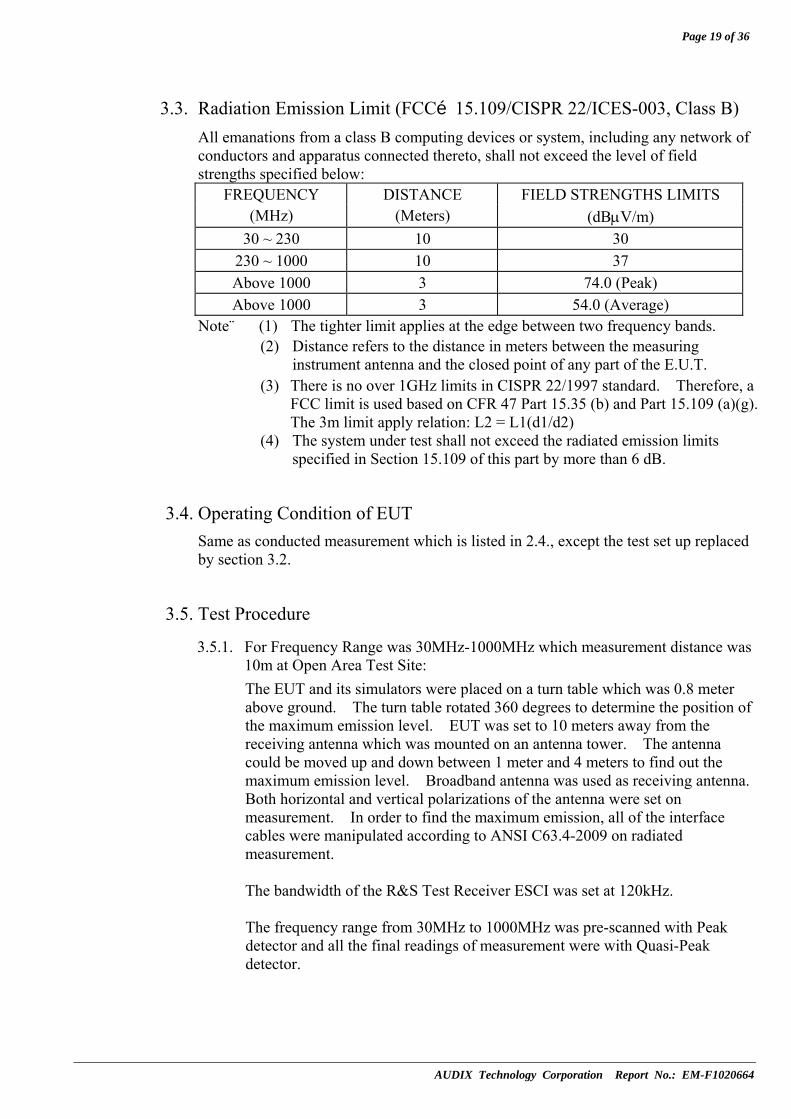
3.3. Radiation Emission Limit (FCC§15.109/CISPR 22/ICES-003, Class B) All emanations from a class B computing devices or system, including any network of conductors and apparatus connected thereto, shall not exceed the level of field strengths specified below:
FREQUENCY DISTANCE FIELD STRENGTHS LIMITS (MHz) (Meters) (dBμV/m)
30 ~ 230 10 30 230 ~ 1000 10 37 Above 1000 3 74.0 (Peak) Above 1000 3 54.0 (Average)
Note: (1) The tighter limit applies at the edge between two frequency bands. (2) Distance refers to the distance in meters between the measuring
instrument antenna and the closed point of any part of the E.U.T. (3) There is no over 1GHz limits in CISPR 22/1997 standard. Therefore, a
FCC limit is used based on CFR 47 Part 15.35 (b) and Part 15.109 (a)(g). The 3m limit apply relation: L2 = L1(d1/d2)
(4) The system under test shall not exceed the radiated emission limits specified in Section 15.109 of this part by more than 6 dB.
3.4. Operating Condition of EUT Same as conducted measurement which is listed in 2.4., except the test set up replaced by section 3.2.
3.5. Test Procedure
3.5.1. For Frequency Range was 30MHz-1000MHz which measurement distance was 10m at Open Area Test Site: The EUT and its simulators were placed on a turn table which was 0.8 meter above ground. The turn table rotated 360 degrees to determine the position of the maximum emission level. EUT was set to 10 meters away from the receiving antenna which was mounted on an antenna tower. The antenna could be moved up and down between 1 meter and 4 meters to find out the maximum emission level. Broadband antenna was used as receiving antenna. Both horizontal and vertical polarizations of the antenna were set on measurement. In order to find the maximum emission, all of the interface cables were manipulated according to ANSI C63.4-2009 on radiated measurement. The bandwidth of the R&S Test Receiver ESCI was set at 120kHz. The frequency range from 30MHz to 1000MHz was pre-scanned with Peak detector and all the final readings of measurement were with Quasi-Peak detector.

Page 20 of 36
AUDIX Technology Corporation Report No.: EM-F1020664
3.5.2. For Frequency Range was Above 1GHz which measurement distance was 3m at Semi-Anechoic Chamber: The EUT and its simulators were placed on a turn table which was 0.8 meter above ground. The portion of the test volume that was obstructed by absorber placed on the floor (30cm maximum). The turn table rotated 360 degrees to determine the position of the maximum emission level. EUT was set to 3 meters away from the receiving antenna which was mounted on an antenna tower. The antenna could be moved up and down between 1 meter and 4 meters to find out the maximum emission level. A calibrated Horn Antenna was used as a receiving antenna. Both horizontal and vertical polarization of the antenna were set on measurement, and both average and peak emission level were recorded form spectrum analyzer. In order to find the maximum emission level, all the interface cables were manipulated according to ANSI C63.4-2009 on radiated measurement. The resolution bandwidth of Agilent Spectrum Analyzer N9010A-526 was set at 1MHz The frequency range from Above 1GHz was checked with peak and average detector.

Page 21 of 36
AUDIX Technology Corporation Report No.: EM-F1020664
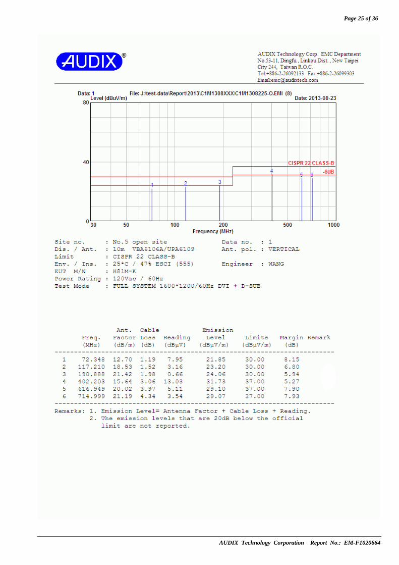
3.6. Radiated Emission Measurement Results PASSED. (All the emissions not reported below are too low against the prescribed limits.) For 30MHz-1000MHz frequency range: The EUT (within PC system) selected the worst test mode (DVI + D-Sub, 1600*1200/60Hz) was performed during this section testing and the test data are listed in 3.6.1. EUT:Motherboard M/N:H81M-K Test Date:Aug. 23, 2013 Temperature:25 Humidity:47% The details are as follows:
Reference Test Data No.Mode Operating of EUT VGA Interface,
Resolutions and Frequencies Horizontal Vertical
※1. Full System (Open Case) DVI + D-Sub, 1600*1200/60Hz # 4 # 3
2. Full System (Close Case) DVI + D-Sub, 1600*1200/60Hz # 2 # 1
※ The system under test shall not exceed the radiated emission limits specified in Section 15.109 of this part by more than 6 dB.
For frequency range above 1GHz: Finally, The EUT (within PC system) selected the worst test mode (DVI + D-Sub, 1920*1200/60Hz) was performed during this section testing and the test data are listed in section 3.6.2. EUT:Motherboard M/N:H81M-K Test Date:Aug. 28, 2013 Temperature:26 Humidity:51% The details are as follows:
Reference Test Data No.Mode Operating of EUT VGA Interface,
Resolutions and Frequencies Horizontal Vertical
1. Full System (Open Case) DVI + D-Sub, 1920*1200/60Hz # 7 # 8
2. Full System (Close Case) DVI + D-Sub, 1920*1200/60Hz # 5 # 6

Page 22 of 36
AUDIX Technology Corporation Report No.: EM-F1020664
3.6.1. Radiated Emission Measurement Results at Open Area Test Site (Frequency Range 30-1000MHz)
3. The worst emission was detected at 132.925MHz with corrected
signal level of 29.18dBμV/m (limit is 30.0dBμV/m) when the antenna was at horizontal polarization and was at 4m high and the turn table was at 115°.
4. 0°was the table front facing the antenna. Degree is calculated from 0°clockwise facing the antenna.
5. The EUT with open case was measured, the limit not exceed the radiated emission limits specified in Section 15.109 of this part by more than 6 dB.
*

Page 23 of 36
AUDIX Technology Corporation Report No.: EM-F1020664
3. The worst emission was detected at 190.205MHz with corrected
signal level of 26.81dBμV/m (limit is 30.0dBμV/m) when the antenna was at vertical polarization and was at 1m high and the turn table was at 270°.
4. 0°was the table front facing the antenna. Degree is calculated from 0°clockwise facing the antenna.
5. The EUT with open case was measured, the limit not exceed the radiated emission limits specified in Section 15.109 of this part by more than 6 dB.
*

Page 24 of 36
AUDIX Technology Corporation Report No.: EM-F1020664
Page 25 of 36
AUDIX Technology Corporation Report No.: EM-F1020664

Page 26 of 36
AUDIX Technology Corporation Report No.: EM-F1020664
3.6.2. Radiated Emission Measurement Results at Semi-Anechoic Chamber
(Frequency Range Above 1GHz)

Page 27 of 36
AUDIX Technology Corporation Report No.: EM-F1020664

Page 28 of 36
AUDIX Technology Corporation Report No.: EM-F1020664

Page 29 of 36
AUDIX Technology Corporation Report No.: EM-F1020664

Page 30 of 36
AUDIX Technology Corporation Report No.: EM-F1020664
4. DEVIATION TO TEST SPECIFICATIONS
【NONE】

Page 31 of 36
AUDIX Technology Corporation Report No.: EM-F1020664
5. PHOTOGRAPHS
5.1. Photos of Powerline Conducted Emission Measurement
FRONT VIEW OF CONDUCTED MEASUREMENT
BACK VIEW OF CONDUCTED MEASUREMENT
Page 32 of 36
AUDIX Technology Corporation Report No.: EM-F1020664
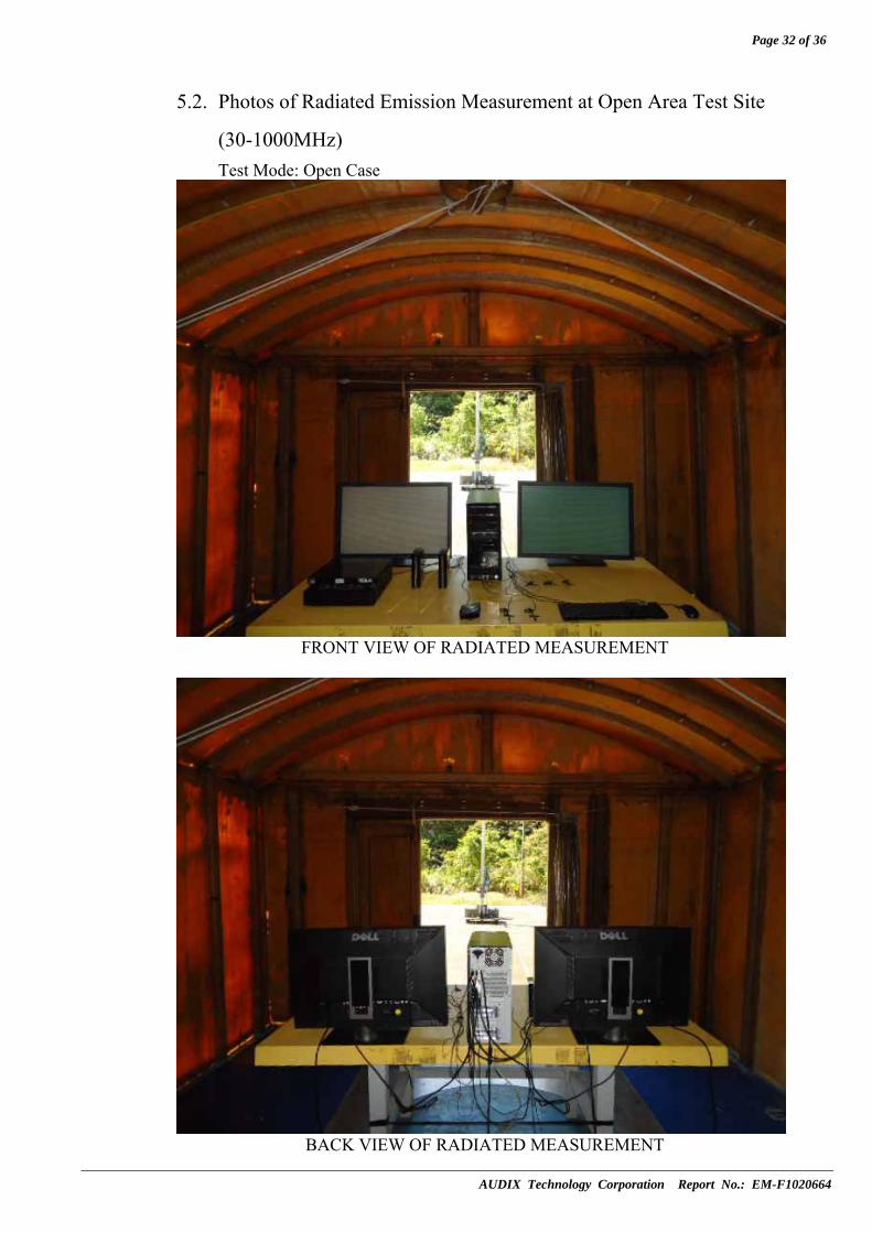
5.2. Photos of Radiated Emission Measurement at Open Area Test Site
(30-1000MHz) Test Mode: Open Case
FRONT VIEW OF RADIATED MEASUREMENT
BACK VIEW OF RADIATED MEASUREMENT

Page 33 of 36
AUDIX Technology Corporation Report No.: EM-F1020664
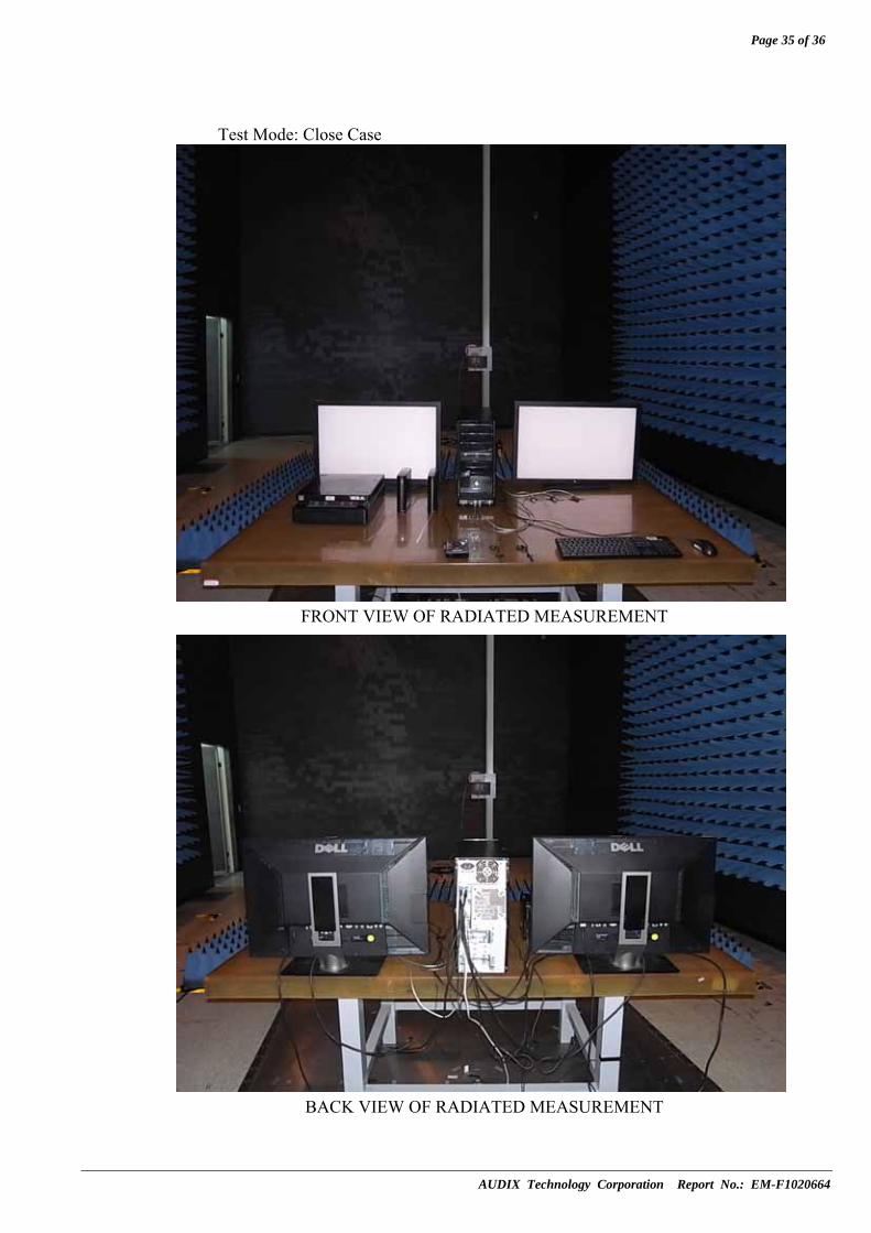
Test Mode: Close Case
FRONT VIEW OF RADIATED MEASUREMENT
BACK VIEW OF RADIATED MEASUREMENT
Page 34 of 36
AUDIX Technology Corporation Report No.: EM-F1020664
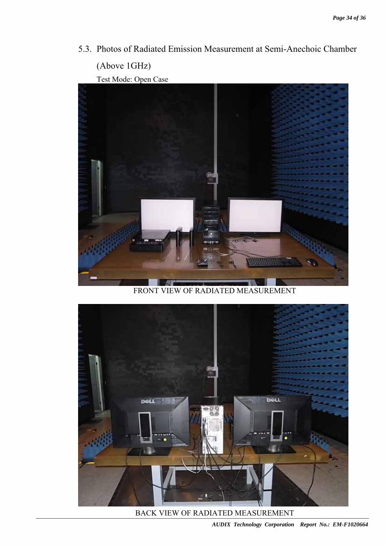
5.3. Photos of Radiated Emission Measurement at Semi-Anechoic Chamber
(Above 1GHz) Test Mode: Open Case
FRONT VIEW OF RADIATED MEASUREMENT
BACK VIEW OF RADIATED MEASUREMENT
Page 35 of 36
AUDIX Technology Corporation Report No.: EM-F1020664
Test Mode: Close Case
FRONT VIEW OF RADIATED MEASUREMENT
BACK VIEW OF RADIATED MEASUREMENT

Page 36 of 36
AUDIX Technology Corporation Report No.: EM-F1020664
5.4. Partner System

APPENDIX I
AUDIX Technology Corporation Report No.: EM-F1020664
APPENDIX I
(Photos of EUT)
(Total Page: 2 Pages)

APPENDIX I - Page 1 of 2
AUDIX Technology Corporation Report No.: EM-F1020664
Figure 1
Motherboard (Front View)
Figure 2 Motherboard (Back View)

APPENDIX I - Page 2 of 2
AUDIX Technology Corporation Report No.: EM-F1020664
Figure 3
Motherboard (Side View, I/O Ports)