for the dvc digital voice command system daa2 and dax ...fpssa.com.ar/sharre/14 daa2 and dax...
TRANSCRIPT
C2P/N 53265:C2 ECN 13-0775
Document 532659/11/2013 Rev:
For the DVC Digital VoiceCommand System
DAA2 and DAXAmplifiers
Manual
2 DAA2 & DAX — P/N 53265:C2 9/11/2013
Fire Alarm & Emergency Communication System LimitationsWhile a life safety system may lower insurance rates, it is not a substitute for life and property insurance!An automatic fire alarm system—typically made up of smoke detectors, heat detectors, manual pull stations, audible warning devices, and a fire alarm control panel (FACP) with remote notifi-cation capability—can provide early warning of a developing fire. Such a system, however, does not assure protection against property damage or loss of life resulting from a fire.
An emergency communication system—typically made up of an automatic fire alarm system (as described above) and a life safety communication system that may include an autonomous control unit (ACU), local operating console (LOC), voice commu-nication, and other various interoperable communication meth-ods—can broadcast a mass notification message. Such a system, however, does not assure protection against property damage or loss of life resulting from a fire or life safety event.
The Manufacturer recommends that smoke and/or heat detectors be located throughout a protected premises following the recommendations of the current edition of the National Fire Protection Association Standard 72 (NFPA 72), manufacturer's recommendations, State and local codes, and the recommendations contained in the Guide for Proper Use of System Smoke Detectors, which is made available at no charge to all installing dealers. This document can be found at http://www.systemsensor.com/appguides/. A study by the Federal Emergency Management Agency (an agency of the United States government) indicated that smoke detectors may not go off in as many as 35% of all fires. While fire alarm systems are designed to provide early warning against fire, they do not guarantee warning or protection against fire. A fire alarm system may not provide timely or adequate warning, or simply may not function, for a variety of reasons:
Smoke detectors may not sense fire where smoke cannot reach the detectors such as in chimneys, in or behind walls, on roofs, or on the other side of closed doors. Smoke detectors also may not sense a fire on another level or floor of a building. A second-floor detector, for example, may not sense a first-floor or basement fire.
Particles of combustion or “smoke” from a developing fire may not reach the sensing chambers of smoke detectors because:
• Barriers such as closed or partially closed doors, walls, chim-neys, even wet or humid areas may inhibit particle or smoke flow.
• Smoke particles may become “cold,” stratify, and not reach the ceiling or upper walls where detectors are located.
• Smoke particles may be blown away from detectors by air outlets, such as air conditioning vents.
• Smoke particles may be drawn into air returns before reach-ing the detector.
The amount of “smoke” present may be insufficient to alarm smoke detectors. Smoke detectors are designed to alarm at var-ious levels of smoke density. If such density levels are not cre-ated by a developing fire at the location of detectors, the detectors will not go into alarm.
Smoke detectors, even when working properly, have sensing limitations. Detectors that have photoelectronic sensing cham-bers tend to detect smoldering fires better than flaming fires, which have little visible smoke. Detectors that have ionizing-type sensing chambers tend to detect fast-flaming fires better than smoldering fires. Because fires develop in different ways and are often unpredictable in their growth, neither type of detector is necessarily best and a given type of detector may not provide adequate warning of a fire.
Smoke detectors cannot be expected to provide adequate warn-ing of fires caused by arson, children playing with matches (especially in bedrooms), smoking in bed, and violent explosions (caused by escaping gas, improper storage of flammable materi-als, etc.).
Heat detectors do not sense particles of combustion and alarm only when heat on their sensors increases at a predetermined rate or reaches a predetermined level. Rate-of-rise heat detec-tors may be subject to reduced sensitivity over time. For this reason, the rate-of-rise feature of each detector should be tested at least once per year by a qualified fire protection specialist. Heat detectors are designed to protect property, not life.
IMPORTANT! Smoke detectors must be installed in the same room as the control panel and in rooms used by the system for the connection of alarm transmission wiring, communications, signaling, and/or power. If detectors are not so located, a devel-oping fire may damage the alarm system, compromising its abil-ity to report a fire.
Audible warning devices such as bells, horns, strobes, speakers and displays may not alert people if these devices are located on the other side of closed or partly open doors or are located on another floor of a building. Any warning device may fail to alert people with a disability or those who have recently consumed drugs, alcohol, or medication. Please note that:
• An emergency communication system may take priority over a fire alarm system in the event of a life safety emergency.
• Voice messaging systems must be designed to meet intelligi-bility requirements as defined by NFPA, local codes, and Authorities Having Jurisdiction (AHJ).
• Language and instructional requirements must be clearly dis-seminated on any local displays.
• Strobes can, under certain circumstances, cause seizures in people with conditions such as epilepsy.
• Studies have shown that certain people, even when they hear a fire alarm signal, do not respond to or comprehend the meaning of the signal. Audible devices, such as horns and bells, can have different tonal patterns and frequencies. It is the property owner's responsibility to conduct fire drills and other training exercises to make people aware of fire alarm signals and instruct them on the proper reaction to alarm sig-nals.
• In rare instances, the sounding of a warning device can cause temporary or permanent hearing loss.
A life safety system will not operate without any electrical power. If AC power fails, the system will operate from standby batteries only for a specified time and only if the batteries have been properly maintained and replaced regularly.
Equipment used in the system may not be technically compat-ible with the control panel. It is essential to use only equipment listed for service with your control panel.
Telephone lines needed to transmit alarm signals from a prem-ises to a central monitoring station may be out of service or tem-porarily disabled. For added protection against telephone line failure, backup radio transmission systems are recommended.
The most common cause of life safety system malfunction is inadequate maintenance. To keep the entire life safety system in excellent working order, ongoing maintenance is required per the manufacturer's recommendations, and UL and NFPA stan-dards. At a minimum, the requirements of NFPA 72 shall be fol-lowed. Environments with large amounts of dust, dirt, or high air velocity require more frequent maintenance. A maintenance agreement should be arranged through the local manufacturer's representative. Maintenance should be scheduled monthly or as required by National and/or local fire codes and should be per-formed by authorized professional life saftety system installers only. Adequate written records of all inspections should be kept.
Limit-D-1-2013

DAA2 & DAX — P/N 53265:C2 9/11/2013 3
Installation PrecautionsAdherence to the following will aid in problem-free installation with long-term reliability:WARNING - Several different sources of power can be connected to the fire alarm control panel. Disconnect all sources of power before servicing. Control unit and associ-ated equipment may be damaged by removing and/or insert-ing cards, modules, or interconnecting cables while the unit is energized. Do not attempt to install, service, or operate this unit until manuals are read and understood.
CAUTION - System Re-acceptance Test after Software Changes: To ensure proper system operation, this product must be tested in accordance with NFPA 72 after any pro-gramming operation or change in site-specific software. Re-acceptance testing is required after any change, addition or deletion of system components, or after any modification, repair or adjustment to system hardware or wiring. All compo-nents, circuits, system operations, or software functions known to be affected by a change must be 100% tested. In addition, to ensure that other operations are not inadvertently affected, at least 10% of initiating devices that are not directly affected by the change, up to a maximum of 50 devices, must also be tested and proper system operation verified.
This system meets NFPA requirements for operation at 0-49º C/32-120º F and at a relative humidity 93% ± 2% RH (non-condensing) at 32°C ± 2°C (90°F ± 3°F). However, the useful life of the system's standby batteries and the electronic com-ponents may be adversely affected by extreme temperature ranges and humidity. Therefore, it is recommended that this system and its peripherals be installed in an environment with a normal room temperature of 15-27º C/60-80º F.
Verify that wire sizes are adequate for all initiating and indi-cating device loops. Most devices cannot tolerate more than a 10% I.R. drop from the specified device voltage.
Like all solid state electronic devices, this system may operate erratically or can be damaged when subjected to light-ning induced transients. Although no system is completely immune from lightning transients and interference, proper grounding will reduce susceptibility. Overhead or outside aerial wiring is not recommended, due to an increased susceptibility to nearby lightning strikes. Consult with the Technical Ser-vices Department if any problems are anticipated or encoun-tered.
Disconnect AC power and batteries prior to removing or inserting circuit boards. Failure to do so can damage circuits.
Remove all electronic assemblies prior to any drilling, filing, reaming, or punching of the enclosure. When possible, make all cable entries from the sides or rear. Before making modifi-cations, verify that they will not interfere with battery, trans-former, or printed circuit board location.
Do not tighten screw terminals more than 9 in-lbs. Over-tightening may damage threads, resulting in reduced terminal contact pressure and difficulty with screw terminal removal.
This system contains static-sensitive components. Always ground yourself with a proper wrist strap before han-dling any circuits so that static charges are removed from the body. Use static suppressive packaging to protect electronic assemblies removed from the unit.
Follow the instructions in the installation, operating, and pro-gramming manuals. These instructions must be followed to avoid damage to the control panel and associated equipment. FACP operation and reliability depend upon proper installation.
Precau-D1-9-2005
FCC WarningWARNING: This equipment generates, uses, and can radiate radio frequency energy and if not installed and used in accordance with the instruction manual may cause interference to radio communications. It has been tested and found to comply with the limits for class A computing devices pursuant to Subpart B of Part 15 of FCC Rules, which is designed to provide reasonable protection against such interference when devices are operated in a commercial environment. Operation of this equipment in a residential area is likely to cause interfer-ence, in which case the user will be required to correct the interference at his or her own expense.
Canadian Requirements
This digital apparatus does not exceed the Class A limits for radiation noise emissions from digital apparatus set out in the Radio Interference Regulations of the Cana-dian Department of Communications.
Le present appareil numerique n'emet pas de bruits radi-oelectriques depassant les limites applicables aux appa-reils numeriques de la classe A prescrites dans le Reglement sur le brouillage radioelectrique edicte par le ministere des Communications du Canada.
HARSH™, NIS™, and NOTI•FIRE•NET™ are all trademarks; and Acclimate® Plus, FlashScan®, NION®, NOTIFIER®, ONYX®, ONYXWorks®, UniNet®,VeriFire®, and VIEW® are all registered trademarks of Honeywell International Inc. Echelon® is a registered trademark and LonWorks™ is a trademark ofEchelon Corporation. ARCNET® is a registered trademark of Datapoint Corporation. Microsoft® and Windows® are registered trademarks of the MicrosoftCorporation.
©2013 by Honeywell International Inc. All rights reserved. Unauthorized use of this document is strictly prohibited.

4 DAA2 & DAX — P/N 53265:C2 9/11/2013
Software DownloadsIn order to supply the latest features and functionality in fire alarm and life safety technology to our customers, we make frequent upgrades to the embedded software in our products. To ensure that you are installing and programming the latest features, we strongly recommend that you download the most current version of software for each product prior to commissioning any system. Contact Technical Support with any questions about software and the appropriate version for a specific application.
Documentation FeedbackYour feedback helps us keep our documentation up-to-date and accurate. If you have any comments or suggestions about our online Help or printed manuals, you can email us.
Please include the following information:
•Product name and version number (if applicable)
•Printed manual or online Help
•Topic Title (for online Help)
•Page number (for printed manual)
•Brief description of content you think should be improved or corrected
•Your suggestion for how to correct/improve documentation
Send email messages to:
Please note this email address is for documentation feedback only. If you have any technical issues, please contact Technical Services.
Table of Contents
DAA2 & DAX — P/N 53265:C2 9/11/2013 5
Table of Contents
Section 1: General Information................................................................................................91.1: Overview........................................................................................................................................................91.2: Standards and Other Documents....................................................................................................................91.3: Supplemental Documentation......................................................................................................................101.4: Cautions and Warnings ................................................................................................................................10
Section 2: DAA2 Digital Audio Amplifiers ............................................................................ 112.1: Description...................................................................................................................................................11
2.1.1: Features..............................................................................................................................................112.1.2: Specifications.....................................................................................................................................12
CPS-24 Power Supply Board ...............................................................................................................12DAA2-5025/70 and DAA2-7525 Boards.............................................................................................13
2.1.3: DAA2 Layout ....................................................................................................................................15Connection Locations...........................................................................................................................15Indicators ..............................................................................................................................................18Switches................................................................................................................................................19
2.2: DAA2 Installation........................................................................................................................................192.2.1: Cabinet...............................................................................................................................................19
EQ Series Cabinets and Doors .............................................................................................................20CAB-4 Series........................................................................................................................................22
2.2.2: Batteries .............................................................................................................................................22CHS-BH1 Battery Chassis ...................................................................................................................23Within the CAB-4 Enclosure................................................................................................................23Outside the DAA2 Enclosure ...............................................................................................................23
2.2.3: Wiring................................................................................................................................................23AC Power .............................................................................................................................................23Batteries................................................................................................................................................24Alarm Bus.............................................................................................................................................25Digital Audio Ports A and B, Wire Connections .................................................................................27Digital Audio Ports A and B, Fiber and Wire/Fiber Connections........................................................27FFT Riser Connections.........................................................................................................................28RM-1 Remote Microphone Interface ...................................................................................................30Auxiliary Input A .................................................................................................................................30Speaker Circuits....................................................................................................................................30Wiring Fault Testing.............................................................................................................................38UL Power-limited (Class 2) Wiring Requirements ..............................................................................39
2.3: DAA2 Configuration ...................................................................................................................................402.3.1: Setting the Configuration Switches ...................................................................................................40
GND Fault Switch - SW1 on CPS-24 ..................................................................................................402WIRE/4WIRE Switch - SW1 on DAA2 Board..................................................................................40Address Switches - SW2, SW3 ............................................................................................................40PRIMARY AMP Switch - SW4...........................................................................................................41
2.3.2: Programming .....................................................................................................................................412.4: DAA2 Operation..........................................................................................................................................41
2.4.1: Sig Sil Control ...................................................................................................................................412.4.2: Volume Control - Master and Auxiliary............................................................................................412.4.3: FFT Communication .........................................................................................................................412.4.4: Trouble Messages ..............................................................................................................................412.4.5: Read/Alter Status...............................................................................................................................41
Section 3: DAX Digital Audio Amplifiers .............................................................................. 423.1: DAX Overview............................................................................................................................................42
3.1.1: Description.........................................................................................................................................423.1.2: Features..............................................................................................................................................423.1.3: Specifications.....................................................................................................................................43
Table of Contents
6 DAA2 & DAX — P/N 53265:C2 9/11/2013
AC Power - TB7 ...................................................................................................................................43Battery Connections - TB8, TB9..........................................................................................................43Battery Charger (DAX-35 Boards Only)..............................................................................................43Wire Digital Audio Ports A and B - TB1, TB2 ....................................................................................43Alarm Bus - TB3 ..................................................................................................................................43Speaker Circuits - TB4 and TB5 ..........................................................................................................44Backup from Alternate Amplifier - TB10 and TB11 ...........................................................................44
3.1.4: DAX Board Layouts ..........................................................................................................................45Connection Locations ...........................................................................................................................45DAX Indicators, Switches, and Jumper................................................................................................46Switches and Jumper ............................................................................................................................47
3.2: DAX Installation..........................................................................................................................................473.2.1: Cabinet ...............................................................................................................................................47
EQ Series Cabinets and Doors..............................................................................................................48CAB-4 Series ........................................................................................................................................50
3.2.2: Batteries .............................................................................................................................................50Within the CAB-4 Enclosure................................................................................................................51Outside the DAX Enclosure .................................................................................................................51
3.2.3: Wiring ................................................................................................................................................51AC Power..............................................................................................................................................51Batteries ................................................................................................................................................51Alarm Bus.............................................................................................................................................54Digital Audio Ports A and B.................................................................................................................55Speaker and Backup Circuits................................................................................................................56Wiring Fault Testing.............................................................................................................................63UL Power-limited (Class 2) Wiring Requirements ..............................................................................64
3.3: DAX Configuration .....................................................................................................................................653.3.1: Setting the Configuration Switches ...................................................................................................65
EARTH FAULT (Switch 5) - DAX-35 Only .......................................................................................65Address Switches..................................................................................................................................65
3.3.2: Programming .....................................................................................................................................653.4: DAX Operation ............................................................................................................................................65
3.4.1: Volume ..............................................................................................................................................653.4.2: Trouble Messages ..............................................................................................................................653.4.3: Read/Alter Status ...............................................................................................................................66
Section 4: BDA Backup Digital Amplifiers ........................................................................... 674.1: Features ........................................................................................................................................................674.2: Specifications ...............................................................................................................................................67
4.2.1: When Used with DAA2-75 ...............................................................................................................674.2.2: When Used with DAA2-50 ...............................................................................................................674.2.3: When Used with DAX-50 .................................................................................................................684.2.4: When Used with DAX-35 .................................................................................................................68
4.3: Board Layout ...............................................................................................................................................684.4: Installation....................................................................................................................................................69
4.4.1: DAA2.................................................................................................................................................694.4.2: DAX...................................................................................................................................................704.4.3: BDA Power and Control Cables........................................................................................................70
4.5: Configuration ...............................................................................................................................................714.5.1: Wattage Switches, SW5 - SW7 .........................................................................................................714.5.2: FAIL TEST Switch, SW4..................................................................................................................714.5.3: DAA2-50 Configurations with BDA.................................................................................................72
DAA2-75 Configurations with BDA....................................................................................................734.5.4: Operation ...........................................................................................................................................74
Volume .................................................................................................................................................74
Section 5: Fiber Option Modules........................................................................................... 755.1: Specifications ...............................................................................................................................................75
Table of Contents
DAA2 & DAX — P/N 53265:C2 9/11/2013 7
5.2: Layout ..........................................................................................................................................................765.3: Installation ...................................................................................................................................................77
5.3.1: DAA2 Installation..............................................................................................................................775.3.2: DAX Installation................................................................................................................................775.3.3: Single- or Multi-mode DVC (DVC-PCB or less) or DAA Installation ............................................78
Single-mode..........................................................................................................................................78Multi-mode ...........................................................................................................................................78
Appendix A: AC Current Draw Calculations ........................................................................79A.1: DAA2 Current Draw Calculations..............................................................................................................79
A.1.1: Worksheet Procedures ......................................................................................................................79A.1.2: Worksheets .......................................................................................................................................79
A.2: DAX Current Draw Calculations................................................................................................................81A.2.1: Worksheet Procedures ......................................................................................................................81A.2.2: Worksheets .......................................................................................................................................81
Appendix B: Battery Calculations ......................................................................................... 84B.1: DAA2 Battery Calculations ......................................................................................................................84B.2: DAX Battery Calculations ..........................................................................................................................86
Appendix C: DAA Digital Audio Amplifiers .......................................................................... 88C.1: Overview.....................................................................................................................................................88
C.1.1: Description........................................................................................................................................88C.1.2: Features .............................................................................................................................................89C.1.3: Specifications....................................................................................................................................90
DAA-PS Power Supply Board .............................................................................................................90DAA-5025/70 and DAA-7525 Boards.................................................................................................90
C.1.4: DAA Board Layouts .........................................................................................................................93Wire Versions.......................................................................................................................................93Fiber Versions ......................................................................................................................................95Indicators ..............................................................................................................................................96Switches and Jumper ............................................................................................................................98
C.2: Installation...................................................................................................................................................98C.2.1: Cabinet ..............................................................................................................................................98
CAB-3 Cabinets....................................................................................................................................99CAB-4 Series......................................................................................................................................100EQCAB Series Cabinets.....................................................................................................................100
C.2.2: Batteries ..........................................................................................................................................101In a CHS-BH1 Battery Chassis ..........................................................................................................102Within the CAB-4 Enclosure..............................................................................................................102Outside the DAA Enclosure ...............................................................................................................102
C.2.3: Wiring .............................................................................................................................................102Connecting the DAA Power Supply to AC Power.............................................................................102Connecting the DAA Power Supply to the Batteries .........................................................................103Connecting the Alarm and Trouble Buses..........................................................................................106Digital Audio Ports A and B on Wire Version Boards ......................................................................108RXA, RXB, TXA, TXB Fiber Version Board Connections ..............................................................108FFT Riser Connections.......................................................................................................................109Auxiliary Inputs A and B ...................................................................................................................110Speaker and Backup Circuits..............................................................................................................111In Riser Mode to CIM/CSM Series Canadian Room Isolator Modules.............................................115UL Power-limited (Class 2) Wiring Requirements ............................................................................118
C.3: Configuration ............................................................................................................................................119C.3.1: Setting the Configuration Switches ................................................................................................119
EFA and EFB (Switches 9 and 10).....................................................................................................1194WIRE (Switch 11) ............................................................................................................................119Address Switches................................................................................................................................120

Table of Contents
8 DAA2 & DAX — P/N 53265:C2 9/11/2013
Volume Control ..................................................................................................................................120C.4: Programming.............................................................................................................................................120C.5: Operation...................................................................................................................................................120
C.5.1: Pushbutton Controls ........................................................................................................................120C.5.2: Volume Control...............................................................................................................................121C.5.3: Read/Alter Status ............................................................................................................................121C.5.4: FFT Communication .......................................................................................................................121C.5.5: Trouble Messages ...........................................................................................................................121
C.6: Battery Calculations ..................................................................................................................................121
Index ...................................................................................................................................... 124
DAA2 & DAX — P/N 53265:C2 9/11/2013 9
Section 1: General Information
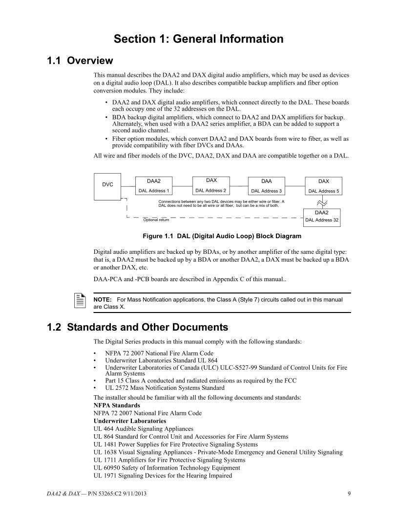
1.1 OverviewThis manual describes the DAA2 and DAX digital audio amplifiers, which may be used as devices on a digital audio loop (DAL). It also describes compatible backup amplifiers and fiber option conversion modules. They include:
• DAA2 and DAX digital audio amplifiers, which connect directly to the DAL. These boards each occupy one of the 32 addresses on the DAL.
• BDA backup digital amplifiers, which connect to DAA2 and DAX amplifiers for backup. Alternately, when used with a DAA2 series amplifier, a BDA can be added to support a second audio channel.
• Fiber option modules, which convert DAA2 and DAX boards from wire to fiber, as well as provide compatibility with fiber DVCs and DAAs.
All wire and fiber models of the DVC, DAA2, DAX and DAA are compatible together on a DAL.
Figure 1.1 DAL (Digital Audio Loop) Block Diagram
Digital audio amplifiers are backed up by BDAs, or by another amplifier of the same digital type: that is, a DAA2 must be backed up by a BDA or another DAA2, a DAX must be backed up a BDA or another DAX, etc.
DAA-PCA and -PCB boards are described in Appendix C of this manual..
1.2 Standards and Other DocumentsThe Digital Series products in this manual comply with the following standards:
• NFPA 72 2007 National Fire Alarm Code• Underwriter Laboratories Standard UL 864 • Underwriter Laboratories of Canada (ULC) ULC-S527-99 Standard of Control Units for Fire
Alarm Systems• Part 15 Class A conducted and radiated emissions as required by the FCC• UL 2572 Mass Notification Systems Standard
The installer should be familiar with all the following documents and standards:NFPA StandardsNFPA 72 2007 National Fire Alarm CodeUnderwriter LaboratoriesUL 464 Audible Signaling AppliancesUL 864 Standard for Control Unit and Accessories for Fire Alarm SystemsUL 1481 Power Supplies for Fire Protective Signaling SystemsUL 1638 Visual Signaling Appliances - Private-Mode Emergency and General Utility SignalingUL 1711 Amplifiers for Fire Protective Signaling SystemsUL 60950 Safety of Information Technology EquipmentUL 1971 Signaling Devices for the Hearing Impaired
DVCDAA2 DAXDAA DAX
DAA2
DAL Address 1 DAL Address 5DAL Address 3DAL Address 2
DAL Address 32Optional return
Connections between any two DAL devices may be either wire or fiber. A DAL does not need to be all wire or all fiber, but can be a mix of both.
NOTE: For Mass Notification applications, the Class A (Style 7) circuits called out in this manual are Class X.
10 DAA2 & DAX — P/N 53265:C2 9/11/2013
General Information Supplemental Documentation
UL 2572 Mass Notification Systems StandardUnderwriters Laboratories of Canada (ULC)ULC-S527-99 Standard of Control Units for Fire Alarm SystemsOtherFCC Part 15 Class A Conducted and Radiated Emissions
1.3 Supplemental DocumentationThe table below provides a list of documents referenced in this manual, as well as documents for other compatible devices.
Related Documentation Table
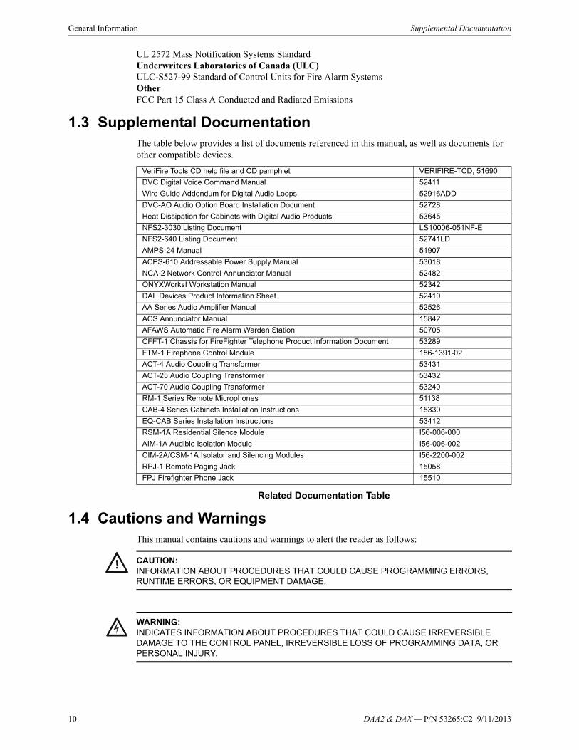
1.4 Cautions and WarningsThis manual contains cautions and warnings to alert the reader as follows:
VeriFire Tools CD help file and CD pamphlet VERIFIRE-TCD, 51690
DVC Digital Voice Command Manual 52411
Wire Guide Addendum for Digital Audio Loops 52916ADD
DVC-AO Audio Option Board Installation Document 52728
Heat Dissipation for Cabinets with Digital Audio Products 53645
NFS2-3030 Listing Document LS10006-051NF-E
NFS2-640 Listing Document 52741LD
AMPS-24 Manual 51907
ACPS-610 Addressable Power Supply Manual 53018
NCA-2 Network Control Annunciator Manual 52482
ONYXWorksI Workstation Manual 52342
DAL Devices Product Information Sheet 52410
AA Series Audio Amplifier Manual 52526
ACS Annunciator Manual 15842
AFAWS Automatic Fire Alarm Warden Station 50705
CFFT-1 Chassis for FireFighter Telephone Product Information Document 53289
FTM-1 Firephone Control Module 156-1391-02
ACT-4 Audio Coupling Transformer 53431
ACT-25 Audio Coupling Transformer 53432
ACT-70 Audio Coupling Transformer 53240
RM-1 Series Remote Microphones 51138
CAB-4 Series Cabinets Installation Instructions 15330
EQ-CAB Series Installation Instructions 53412
RSM-1A Residential Silence Module I56-006-000
AIM-1A Audible Isolation Module I56-006-002
CIM-2A/CSM-1A Isolator and Silencing Modules I56-2200-002
RPJ-1 Remote Paging Jack 15058
FPJ Firefighter Phone Jack 15510
! CAUTION:INFORMATION ABOUT PROCEDURES THAT COULD CAUSE PROGRAMMING ERRORS, RUNTIME ERRORS, OR EQUIPMENT DAMAGE.
!WARNING:INDICATES INFORMATION ABOUT PROCEDURES THAT COULD CAUSE IRREVERSIBLE DAMAGE TO THE CONTROL PANEL, IRREVERSIBLE LOSS OF PROGRAMMING DATA, OR PERSONAL INJURY.
DAA2 & DAX — P/N 53265:C2 9/11/2013 11
Section 2: DAA2 Digital Audio Amplifiers
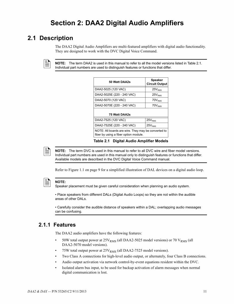
2.1 DescriptionThe DAA2 Digital Audio Amplifiers are multi-featured amplifiers with digital audio functionality. They are designed to work with the DVC Digital Voice Command.
Refer to Figure 1.1 on page 9 for a simplified illustration of DAL devices on a digital audio loop.
2.1.1 Features
The DAA2 audio amplifiers have the following features:
• 50W total output power at 25VRMS (all DAA2-5025 model versions) or 70 VRMS (all DAA2-5070 model versions).
• 75W total output power at 25VRMS (all DAA2-7525 model versions).
• Two Class A connections for high-level audio output, or alternately, four Class B connections.
• Audio output activation via network control-by-event equations resident within the DVC.
• Isolated alarm bus input, to be used for backup activation of alarm messages when normal digital communication is lost.
NOTE: The term DAA2 is used in this manual to refer to all the model versions listed in Table 2.1. Individual part numbers are used to distinguish features or functions that differ.
50 Watt DAA2s Speaker
Circuit Output
DAA2-5025 (120 VAC) 25VRMS
DAA2-5025E (220 - 240 VAC) 25VRMS
DAA2-5070 (120 VAC) 70VRMS
DAA2-5070E (220 - 240 VAC) 70VRMS
75 Watt DAA2s
DAA2-7525 (120 VAC) 25VRMS
DAA2-7525E (220 - 240 VAC) 25VRMS
NOTE: All boards are wire. They may be converted to fiber by using a fiber option module.
Table 2.1 Digital Audio Amplifier Models
NOTE: The term DVC is used in this manual to refer to all DVC wire and fiber model versions. Individual part numbers are used in this manual only to distinguish features or functions that differ. Available models are described in the DVC Digital Voice Command manual.
NOTE:Speaker placement must be given careful consideration when planning an audio system.
• Place speakers from different DALs (Digital Audio Loops) so they are not within the audible areas of other DALs.
• Carefully consider the audible distance of speakers within a DAL; overlapping audio messages can be confusing.
12 DAA2 & DAX — P/N 53265:C2 9/11/2013
DAA2 Digital Audio Amplifiers Description
• Amplifies one channel of digital audio (two channels using the BDA card as a second channel) and distributes it on up to four outputs.
• Remote microphone paging option with RM-1.
• FireFighter telephone (FFT) riser.
• Auxiliary input for 1.6Vp-p max. for each circuit when both AUXA L and AUXA R are used, or 3.2Vp-p max. for one when only one circuit (AUXA L or AUXR) is used, to be used for background music input, an interface with a telephone paging source, or other compatible audio sources. Includes user audio level adjustment feature.
• Uploads and downloads via the DVC. Programmable through VeriFire Tools.
• Up to 106 seconds of Backup Digital message storage (Emergency tone, Non-Emergency tone, and FFT busy tone) for use in the event of communication loss- either standard quality or high quality, from the VeriFire Tools message library or created by the installer.
• Disconnect of deeply-discharged battery (low battery disconnect).
• Backup amplifier options.
• Meets UL THD Distortion requirements for 500 Hz to 4 KHz bandwidth.Meets ULC THD Distortion requirements for 400 Hz to 4 KHz bandwidth.
2.1.2 Specifications
CPS-24 Power Supply Board
AC Power - TB1
120 VAC 60 Hz input*
220-240 VAC 50/60 Hz input (“E” versions)*
*Maximum AC draw varies by DAA2 model. These draws are given in Appendix A, “AC Current Draw Calculations”, along with a worksheet to determine the actual AC draw.
Recommended 12-14 AWG (1.6 mm O.D.) with 600 VAC insulation.
Fuse: 8 amps, 250V, 5 x 20 mm, Fast-Acting, ceramic. Notifier p/n 12117.
Secondary Power 5V and 24V AUX Outputs - TB2
24V AUX:
Power-limited (Class 2): 24V @ 0.5A
Utilizes wire sizes 12-18 AWG (3.31 mm2 - 2.08 mm2)
5V: Future Use
Battery Connections - TB3
Supplied cable connections to batteries for CAB-4 and CHS-BH1. For battery sharing, use 12 AWG either in the same cabinet or in conduit for no more than 20 ft (6.09 m).
Battery Charger
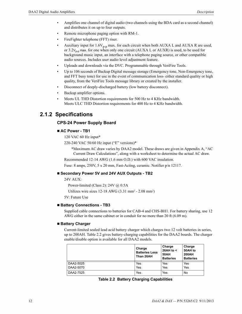
Current-limited sealed lead acid battery charger which charges two 12 volt batteries in series, up to 200AH. Table 2.2 gives battery-charging capabilities for the DAA2 boards. The charger enable/disable option is available for all DAA2 models.
Charge Batteries Less Than 26AH
Charge 26AH to < 50AH Batteries
Charge 50AH to 200AH Batteries
DAA2-5025DAA2-5070
YesYes
YesYes
YesYes
DAA2-7525 Yes Yes No
Table 2.2 Battery Charging Capabilities

DAA2 & DAX — P/N 53265:C2 9/11/2013 13
Description DAA2 Digital Audio Amplifiers
Charger voltage: 27.6 VDC.
For battery calculation worksheet and standby operating times, refer to Appendix B.1, “DAA2 Battery Calculations”, on page 84.
Utilizes wire sizes 12-18 AWG..
When AC power is lost, the deeply-discharged battery cutoff protection will be invoked at 17 volts. The power supply will be disconnected from the batteries. The power supply’s normal operation will be restored when AC power returns.
DAA2-5025/70 and DAA2-7525 Boards
Wire Digital Audio Ports A and B - TB2, TB3
Refer to the Wiring Guide, p/n 52916ADD, for acceptable wire types.
EIA-485 format.
Power-limited (Class 2) and supervised.
Refer to Section 5, “Fiber Option Modules”, on page 75 for fiber connection information. When a fiber option module is mounted on a DAA2, it disables the corresponding wire terminals. TB2 (Digital Audio Port A) is disabled when a fiber option board is connected at J9. TB3 (Digital Audio Port B) is disabled when a fiber option board is connected at J10.
Alarm Bus - TB4
Power-limited (Class 2) and supervised by source.
Recommended wiring: 14-18 AWG twisted-pair.
Requires 16VDC minimum @ 20mA across the terminals to activate. Nominal 24 VDC.
Remote Microphone Interface - TB5
RMI Power - +24VDC, power-limited @ 100mA.
Recommended wiring: 14-18 AWG twisted-pair, Max. 14 AWG.
Nominal AC signal strength 2.5VRMS, 3VRMS Max.
Power-limited (Class 2).
Supervised.
Max. distance between remote microphone and DAA2: 1000 ft (304.8 m).
FFT Riser - TB7
Power-limited (Class 2) output.
Supervised.
Class A or Class B operation.
Class B 2-wire connections require a 3.9k ohm 1/2 watt resistor (P/N R-3.9K).
Max. wiring resistance (including individual telephone zone to last handset) permitted is 50 ohms, 10,000 ft (3048 m) max. wiring distance at 14 AWG to last handset.
DAA2-5025 w/ BDA in Group 2 of VeriFire Tools programming*DAA2-5070 w/ BDA in Group 2 of VeriFire Tools programming*
No
No
No
No
No
No
* Refer to “DAA2-50 Configurations with BDA” on page 72 for further explanation.
Charge Batteries Less Than 26AH
Charge 26AH to < 50AH Batteries
Charge 50AH to 200AH Batteries
Table 2.2 Battery Charging Capabilities
NOTE: A 50 watt DAA2 with 2 groups will have its charger disabled automatically. Groups are explained in the Audio Groups appendix of the DVC Digital Voice Command manual.

14 DAA2 & DAX — P/N 53265:C2 9/11/2013
DAA2 Digital Audio Amplifiers Description
Auxiliary Input A (AUX A) - TB 9
Signal strength from low-level analog audio input (such as background music or telephone paging): 1.6Vp-p max. for each circuit when both AUXA L and AUXA R are used. 3.2Vp-p max. for one when only one (AUXA L or AUXA R) is used.
Optional supervision through programming.
Recommended wiring: 14-18 AWG, twisted-pair.
Supervision programmable.
Auxiliary input source must be within 20 ft. ( 6.1 m) of the DAA2, and within the same room.
Speaker Circuits - TB10, TB11, TB12 and TB13
Power-limited (Class 2) outputs.*
* Exception: A DAA2-5070 speaker circuit used with any Canadian Room Isolator module is non-power-limited. Speaker circuit 1 (TB10) can not be used.
DAA2-5025/70 - Each circuit rated up to 50 watts.**
DAA2-7525 - Each circuit rated up to 75 watts.**
**Total wattage may vary. Refer to “BDA Backup Digital Amplifiers” on page 67 for configurations.
Supervision determined by programming.
25VRMS - DAA2-5025/DAA2-7525 speaker circuits, 70VRMS - DAA2-5070 speaker circuits.
Recommended wiring: 12-18 AWG twisted-pair (shielded recommended).
Class B or Class A:
Class B requires 20k end-of-line resistors (included, P/N ELR-20K).
Class A requires 10k end-of-line resistors (included, P/N R-10K) on the return.
Backup - BKUP1 (TB14), BKUP2 (TB15), BKUP3 (TB16), BKUP4 (TB17)
High-level audio input.
• 25VRMS (DAA2-5025 and DAA2-7525).
• 70VRMS (DAA2-5070).
Recommended wiring: 14-18 AWG twisted-pair (shielded recommended).
Supervision:
•Not supervised when inactive. Supervised by backup source when active.
•Must be in the same room or enclosure.
DAA2 & DAX — P/N 53265:C2 9/11/2013 15
Description DAA2 Digital Audio Amplifiers
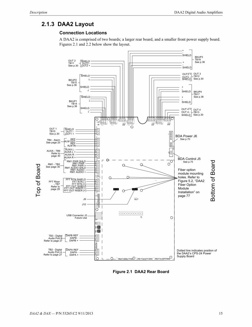
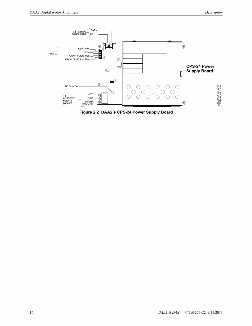
2.1.3 DAA2 Layout
Connection LocationsA DAA2 is comprised of two boards; a larger rear board, and a smaller front power supply board. Figures 2.1 and 2.2 below show the layout.
Figure 2.1 DAA2 Rear Board
OUT 4 +OUT 4 -SHIELD
+-SHIELD
+-SHIELD
SHIELD
+-SHIELD
SHIELDOUT1 -
+-
SHIELD-
+
OUT1 +
SHIELD
OUT3 +OUT3 -
BDA Power J6
BDA Control J5
OUT 3 TB12 See p.30
BKUP3 TB16 See p.36
OUT 4 TB13 See p.30
BKUP4 TB17 See p.36
OUT 1 TB10 See p.30
SHIELD-+BKUP1
TB14 See p.36
OUT 2 TB11 See p.30
SHIELDOUT2 -
OUT2 +
DAPA +DAPA -
DAPA REFTB2 - DigitalAudio Port A
Refer to page 27
DAPB +DAPB -
DAPB REFTB3 - DigitalAudio Port B
Refer to page 27
FFT OUT RISER (+)FFT OUT RISER (-)
FFT OUT SHIELDFFT RTN (+)FFT RTN (-)
FFT RTN SHIELDFFT Riser
- TB7Refer topage 28
AUXA R +AUXA R -AUXA L +AUXA L -
AUXA - TB9Refer topage 30
RM1 AUDIO SHLD
RM1 - TB5See page 30
RM1 AUDIO -RM1 AUDIO +
RM1 PWR SHLDRM1 PWR -RM1 PWR +
ALM IN
ALM OUTREF
REFTB4 - AlarmSee page 25
USB Connector J2Future Use
SHIELD-
+
SHIELD-+BKUP2
TB15 See p.36
Top
of B
oard
Bot
tom
of B
oard
Dotted line indicates position of the DAA2’s CPS-24 Power Supply Board
Fiber option module mounting holes. Refer to Figure 5.2, “DAA2 Fiber Option Module Installation” on page 77
J9
J10
See p.70
See p.70
16 DAA2 & DAX — P/N 53265:C2 9/11/2013
DAA2 Digital Audio Amplifiers Description
Figure 2.2 DAA2’s CPS-24 Power Supply Board
BAT +
BAT -TB3 - BatteryConnections
+24V AUX
COM
COM - Future Use
+5V AUX - Future Use
HOTNEU
EARTHGROUND
TB1AC INPUTRefer to page 23
CPS-24 Power Supply Board
DA
A2
PC
A b
rd.w
mf
CP
S24
-bbo
ard.
wm
f
TB2
AC Fuse F4
DAA2 & DAX — P/N 53265:C2 9/11/2013 17
Description DAA2 Digital Audio Amplifiers
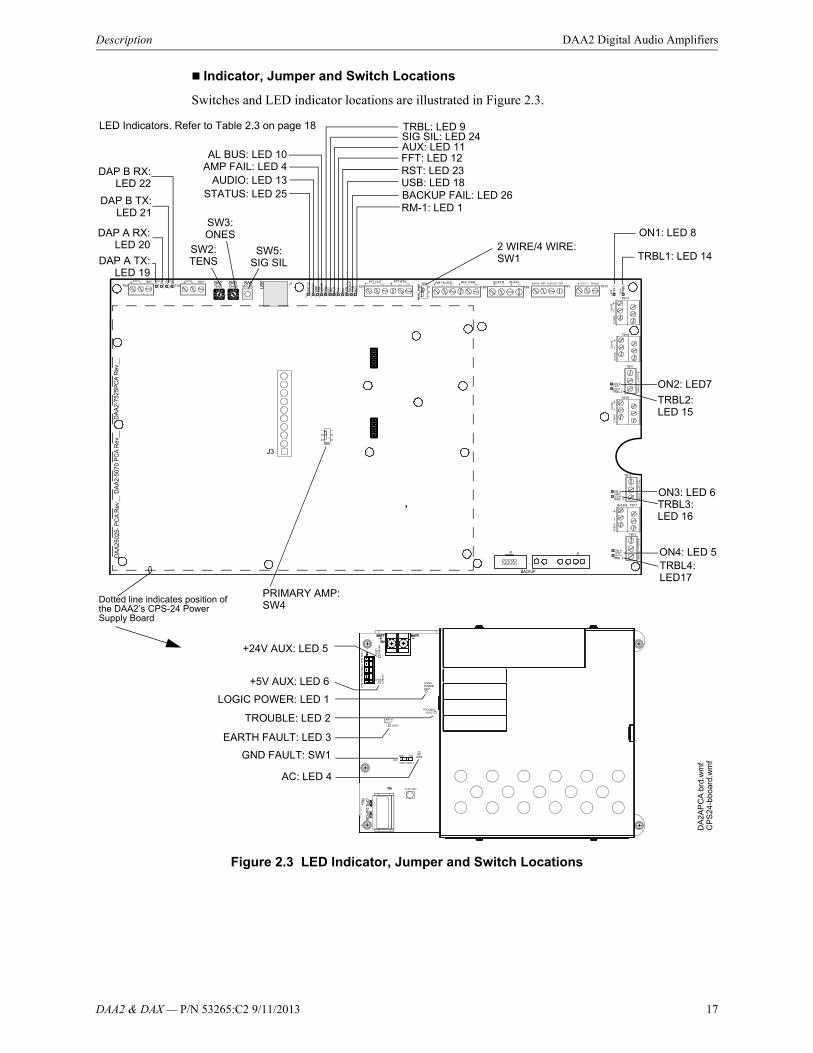
Indicator, Jumper and Switch Locations
Switches and LED indicator locations are illustrated in Figure 2.3.
Figure 2.3 LED Indicator, Jumper and Switch Locations
LED Indicators. Refer to Table 2.3 on page 18
DAP A TX:LED 19
DAP A RX:LED 20
DAP B TX:LED 21
DAP B RX:LED 22
AL BUS: LED 10AMP FAIL: LED 4
AUDIO: LED 13STATUS: LED 25
TRBL: LED 9SIG SIL: LED 24AUX: LED 11FFT: LED 12RST: LED 23USB: LED 18
ON1: LED 8
TRBL1: LED 14
SW3:ONES
SW2:TENS
SW5:SIG SIL
2 WIRE/4 WIRE:SW1
ON2: LED7
TRBL2: LED 15
ON3: LED 6TRBL3: LED 16
ON4: LED 5TRBL4: LED17
DA
2A
PC
A b
rd.w
mf
CP
S24
-bbo
ard
.wm
f
+24V AUX: LED 5
+5V AUX: LED 6
LOGIC POWER: LED 1
TROUBLE: LED 2
EARTH FAULT: LED 3
AC: LED 4
GND FAULT: SW1
BACKUP FAIL: LED 26RM-1: LED 1
Dotted line indicates position of the DAA2’s CPS-24 Power Supply Board
PRIMARY AMP:SW4
18 DAA2 & DAX — P/N 53265:C2 9/11/2013
DAA2 Digital Audio Amplifiers Description
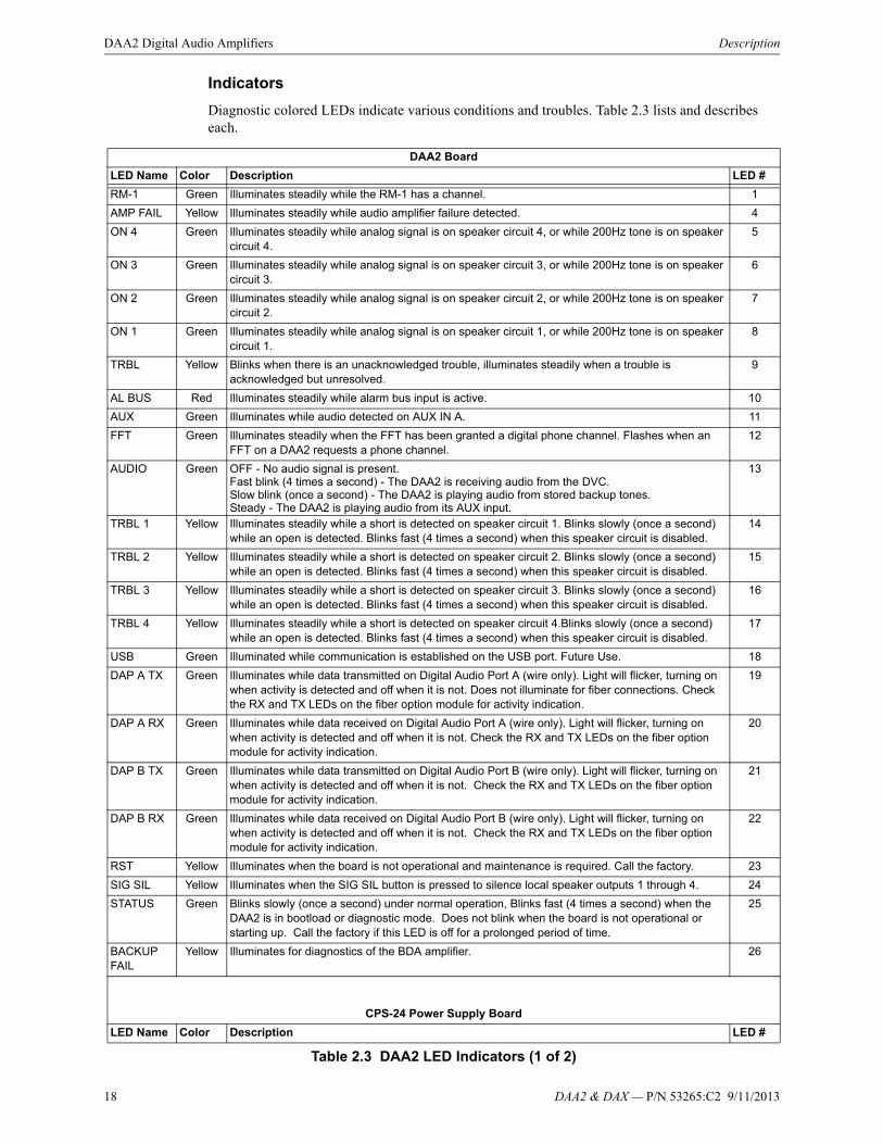
Indicators
Diagnostic colored LEDs indicate various conditions and troubles. Table 2.3 lists and describes each.
DAA2 Board
LED Name Color Description LED #
RM-1 Green Illuminates steadily while the RM-1 has a channel. 1
AMP FAIL Yellow Illuminates steadily while audio amplifier failure detected. 4
ON 4 Green Illuminates steadily while analog signal is on speaker circuit 4, or while 200Hz tone is on speaker circuit 4.
5
ON 3 Green Illuminates steadily while analog signal is on speaker circuit 3, or while 200Hz tone is on speaker circuit 3.
6
ON 2 Green Illuminates steadily while analog signal is on speaker circuit 2, or while 200Hz tone is on speaker circuit 2.
7
ON 1 Green Illuminates steadily while analog signal is on speaker circuit 1, or while 200Hz tone is on speaker circuit 1.
8
TRBL Yellow Blinks when there is an unacknowledged trouble, illuminates steadily when a trouble is acknowledged but unresolved.
9
AL BUS Red Illuminates steadily while alarm bus input is active. 10
AUX Green Illuminates while audio detected on AUX IN A. 11
FFT Green Illuminates steadily when the FFT has been granted a digital phone channel. Flashes when an FFT on a DAA2 requests a phone channel.
12
AUDIO Green OFF - No audio signal is present.Fast blink (4 times a second) - The DAA2 is receiving audio from the DVC.Slow blink (once a second) - The DAA2 is playing audio from stored backup tones.Steady - The DAA2 is playing audio from its AUX input.
13
TRBL 1 Yellow Illuminates steadily while a short is detected on speaker circuit 1. Blinks slowly (once a second) while an open is detected. Blinks fast (4 times a second) when this speaker circuit is disabled.
14
TRBL 2 Yellow Illuminates steadily while a short is detected on speaker circuit 2. Blinks slowly (once a second) while an open is detected. Blinks fast (4 times a second) when this speaker circuit is disabled.
15
TRBL 3 Yellow Illuminates steadily while a short is detected on speaker circuit 3. Blinks slowly (once a second) while an open is detected. Blinks fast (4 times a second) when this speaker circuit is disabled.
16
TRBL 4 Yellow Illuminates steadily while a short is detected on speaker circuit 4.Blinks slowly (once a second) while an open is detected. Blinks fast (4 times a second) when this speaker circuit is disabled.
17
USB Green Illuminated while communication is established on the USB port. Future Use. 18
DAP A TX Green Illuminates while data transmitted on Digital Audio Port A (wire only). Light will flicker, turning on when activity is detected and off when it is not. Does not illuminate for fiber connections. Check the RX and TX LEDs on the fiber option module for activity indication.
19
DAP A RX Green Illuminates while data received on Digital Audio Port A (wire only). Light will flicker, turning on when activity is detected and off when it is not. Check the RX and TX LEDs on the fiber option module for activity indication.
20
DAP B TX Green Illuminates while data transmitted on Digital Audio Port B (wire only). Light will flicker, turning on when activity is detected and off when it is not. Check the RX and TX LEDs on the fiber option module for activity indication.
21
DAP B RX Green Illuminates while data received on Digital Audio Port B (wire only). Light will flicker, turning on when activity is detected and off when it is not. Check the RX and TX LEDs on the fiber option module for activity indication.
22
RST Yellow Illuminates when the board is not operational and maintenance is required. Call the factory. 23
SIG SIL Yellow Illuminates when the SIG SIL button is pressed to silence local speaker outputs 1 through 4. 24
STATUS Green Blinks slowly (once a second) under normal operation, Blinks fast (4 times a second) when the DAA2 is in bootload or diagnostic mode. Does not blink when the board is not operational or starting up. Call the factory if this LED is off for a prolonged period of time.
25
BACKUP FAIL
Yellow Illuminates for diagnostics of the BDA amplifier. 26
CPS-24 Power Supply Board
LED Name Color Description LED #
Table 2.3 DAA2 LED Indicators (1 of 2)
DAA2 & DAX — P/N 53265:C2 9/11/2013 19
DAA2 Installation DAA2 Digital Audio Amplifiers
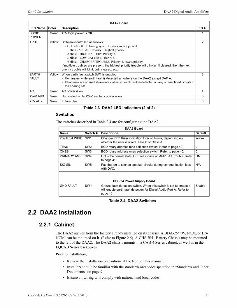
Switches
The switches described in Table 2.4 are for configuring the DAA2.
Table 2.4 DAA2 Switches
2.2 DAA2 Installation
2.2.1 Cabinet
The DAA2 arrives from the factory already installed on its chassis. A BDA-25/70V, NCM, or HS-NCM, can be mounted on it. (Refer to Figure 2.5). A CHS-BH1 Battery Chassis may be mounted to the left of the DAA2. The DAA2 chassis mounts in a CAB-4 Series cabinet, as well as in the EQCAB Series backboxes.
Prior to installation,
• Review the installation precautions at the front of this manual.
• Installers should be familiar with the standards and codes specified in “Standards and Other Documents” on page 9.
• Ensure all wiring will comply with national and local codes.
LOGIC POWER
Green +5V logic power is OK. 1
TRBL Yellow Software-controlled as follows:– OFF when the following system troubles are not present.– 1 blink - AC FAIL. Priority 1, highest priority.– 2 blinks - HIGH BATTERY. Priority 2.– 3 blinks - LOW BATTERY. Priority 3.– 4 blinks - CHARGER TROUBLE. Priority 4, lowest priority.
If multiple troubles are present, the highest priority trouble will blink until cleared, then the next priority trouble will blink until cleared, etc.
2
EARTH FAULT
Yellow When earth fault switch SW1 is enabled:• Illuminates while earth fault is detected anywhere on the DAA2 except DAP A.• If batteries are shared, illuminates when an earth fault is detected on any non-isolated circuits in
the sharing set.
3
AC Green AC power is on. 4
+24V AUX Green Illuminated while +24V auxiliary power is on. 5
+5V AUX Green Future Use 6
DAA2 Board
LED Name Color Description LED #
Table 2.3 DAA2 LED Indicators (2 of 2)
DAA2 Board
Name Switch # Description Default
2 WIRE/4 WIRE SW1 Changes FFT Riser indication to 2- or 4-wire, depending on whether the riser is wired Class B or Class A.
2-wire
TENS SW2 BCD rotary address tens selection switch. Refer to page 40. 0
ONES SW3 BCD rotary address ones selection switch. Refer to page 40. 0
PRIMARY AMP SW4 ON is the normal state. OFF will induce an AMP FAIL trouble. Refer to page 41.
ON
SIG SIL SW5 Pushbutton to silence speaker circuits during communication loss with DVC.
N/A
CPS-24 Power Supply Board
GND FAULT SW 1 Ground fault detection switch. When this switch is set to enable it will enable earth fault detection for Digital Audio Port A. Refer to page 40
Enable
20 DAA2 & DAX — P/N 53265:C2 9/11/2013
DAA2 Digital Audio Amplifiers DAA2 Installation
• Review the installation instructions in this section.
Locate the cabinet backbox on a surface that is in a clean, dry, vibration-free area. The top should be located so that all operational buttons, switches, displays, etc. are easily accessible and/or viewable to the operator - usually no more than 66 inches (1.7 m) above the floor. Allow sufficient clearance around the cabinet for the door to swing freely, and for easy installation and maintenance of equipment.
Follow the instructions below.
1. Mark and pre-drill two holes for the keyhole mounting bolts. Install bolts.
2. Select and punch open the appropriate cabinet knock-outs. (For selection guidelines, see “UL Power-limited (Class 2) Wiring Requirements” on page 39.)
3. Using the keyholes, mount the backbox on the two bolts.
4. Mark the location of the two lower holes, remove backbox and drill the mounting holes.
5. Mount the backbox over the top two screws, then install the remaining fasteners. Tighten all fasteners securely.
6. Feed wires through appropriate knockouts.
7. Install DAA2 according to the following instructions before installing the door per the CAB-4 Series Cabinet Installation Document.
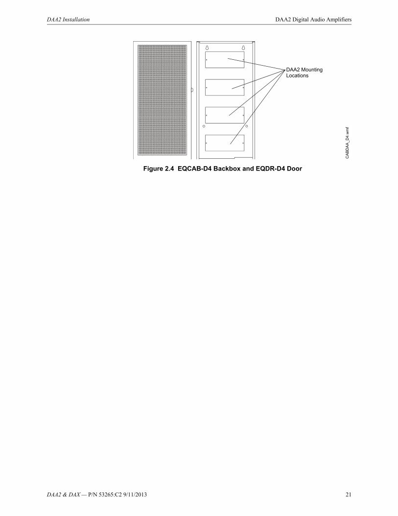
The DAA2 fills one row of any EQ or CAB-4 series cabinet.
EQ Series Cabinets and Doors
The EQ Series cabinets come in B, C, and D sizes. The row spacing allows DAA2 amplifiers to be mounted in any row, and the doors are equipped with ventilated panels for heat dissipation. The cabinets were designed so that all DAA2 boards can be used in any or all cabinet rows. Batteries must be accommodated in separate cabinets or battery backboxes.
The following models are available:
• EQCAB-D4 - Four rows. Accommodates four DAA2s. Consists of P/Ns EQBB-D4 (black backbox) and EQDR-D4 (black door with ventilated panels).
• EQCAB-C4 - Three rows. Accommodates three DAA2s. Consists of P/Ns EQBB-C4 (black backbox) and EQDR-C4 (black door with ventilated panels).
• EQCAB-B4 - Two rows. Accommodates two DAA2s. Consists of P/Ns EQBB-B4 (black backbox) and EQDR-B4 (black door with ventilated panels).
!WARNING:Wear a static discharge wrist strap to prevent equipment damage.
NOTE: Digital amplifiers can produce significant heat during their duty cycles. Different cabinets can handle different amounts of heat. Refer to the Heat Dissipation Calculation document (53645) to determine dissipation figures for the equipment you are installing, and match it with an appropriate cabinet.
DAA2 & DAX — P/N 53265:C2 9/11/2013 21
DAA2 Installation DAA2 Digital Audio Amplifiers
Figure 2.4 EQCAB-D4 Backbox and EQDR-D4 Door
DAA2 Mounting Locations
CA
BD
AA
_D4
.wm
f
22 DAA2 & DAX — P/N 53265:C2 9/11/2013
DAA2 Digital Audio Amplifiers DAA2 Installation
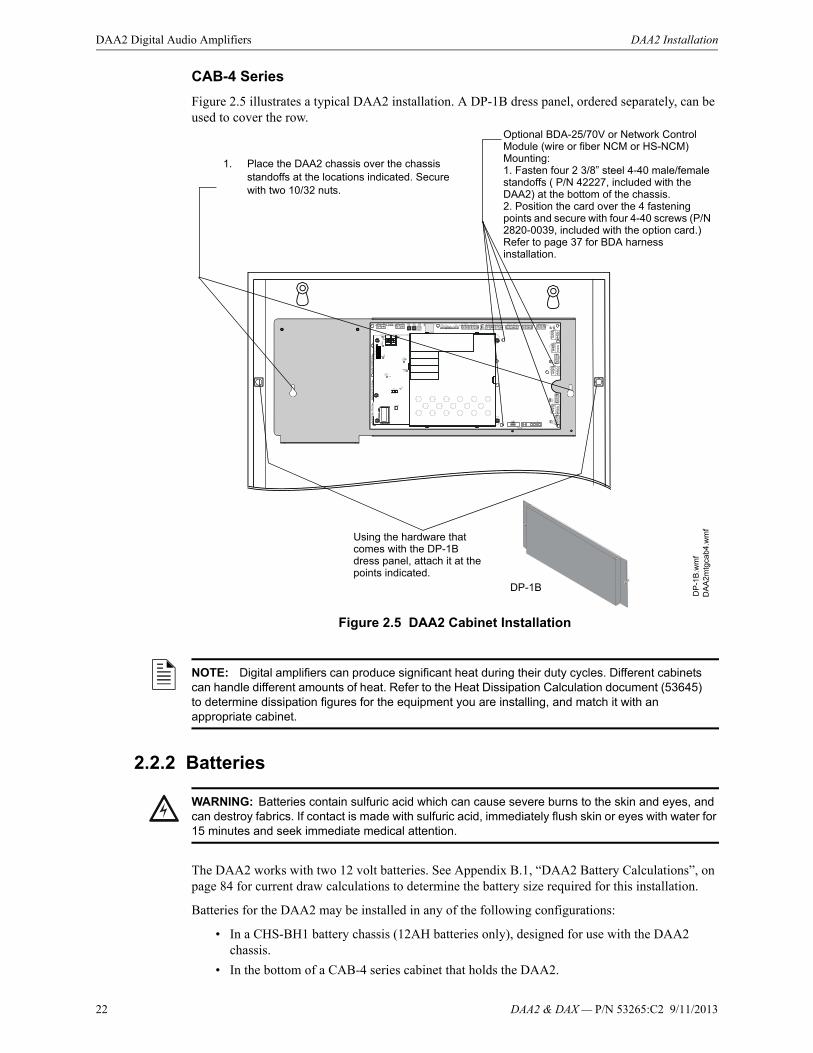
CAB-4 Series
Figure 2.5 illustrates a typical DAA2 installation. A DP-1B dress panel, ordered separately, can be used to cover the row.
Figure 2.5 DAA2 Cabinet Installation
2.2.2 Batteries
The DAA2 works with two 12 volt batteries. See Appendix B.1, “DAA2 Battery Calculations”, on page 84 for current draw calculations to determine the battery size required for this installation.
Batteries for the DAA2 may be installed in any of the following configurations:
• In a CHS-BH1 battery chassis (12AH batteries only), designed for use with the DAA2 chassis.
• In the bottom of a CAB-4 series cabinet that holds the DAA2.
1. Place the DAA2 chassis over the chassis standoffs at the locations indicated. Secure with two 10/32 nuts.
DA
A2
mtg
cab
4.w
mf
Using the hardware that comes with the DP-1B dress panel, attach it at the points indicated.
DP-1B
DP
-1B
.wm
f
Optional BDA-25/70V or Network Control Module (wire or fiber NCM or HS-NCM) Mounting:1. Fasten four 2 3/8” steel 4-40 male/female standoffs ( P/N 42227, included with the DAA2) at the bottom of the chassis.2. Position the card over the 4 fastening points and secure with four 4-40 screws (P/N 2820-0039, included with the option card.)Refer to page 37 for BDA harness installation.
NOTE: Digital amplifiers can produce significant heat during their duty cycles. Different cabinets can handle different amounts of heat. Refer to the Heat Dissipation Calculation document (53645) to determine dissipation figures for the equipment you are installing, and match it with an appropriate cabinet.
!WARNING: Batteries contain sulfuric acid which can cause severe burns to the skin and eyes, and can destroy fabrics. If contact is made with sulfuric acid, immediately flush skin or eyes with water for 15 minutes and seek immediate medical attention.
DAA2 & DAX — P/N 53265:C2 9/11/2013 23
DAA2 Installation DAA2 Digital Audio Amplifiers
• In a cabinet adjacent to the cabinet that holds a DAA2, with connections in conduit.
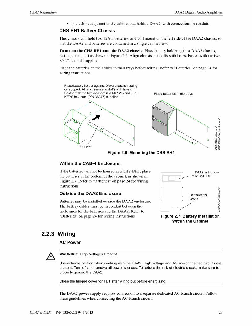
CHS-BH1 Battery Chassis
This chassis will hold two 12AH batteries, and will mount on the left side of the DAA2 chassis, so that the DAA2 and batteries are contained in a single cabinet row.
To mount the CHS-BH1 onto the DAA2 chassis: Place battery holder against DAA2 chassis, resting on support as shown in Figure 2.6. Align chassis standoffs with holes. Fasten with the two 8/32” hex nuts supplied.
Place the batteries on their sides in their trays before wiring. Refer to “Batteries” on page 24 for wiring instructions.
Within the CAB-4 Enclosure
If the batteries will not be housed in a CHS-BH1, place the batteries in the bottom of the cabinet, as shown in Figure 2.7. Refer to “Batteries” on page 24 for wiring instructions.
Outside the DAA2 Enclosure
Batteries may be installed outside the DAA2 enclosure. The battery cables must be in conduit between the enclosures for the batteries and the DAA2. Refer to “Batteries” on page 24 for wiring instructions.
2.2.3 Wiring
AC Power
The DAA2 power supply requires connection to a separate dedicated AC branch circuit. Follow these guidelines when connecting the AC branch circuit:
CH
S-B
Hto
DA
Ach
assi
sa.w
mf
CH
S-B
Hw
batts
a.w
mf
Place battery holder against DAA2 chassis, resting on support. Align chassis standoffs with holes. Fasten with the two washers (P/N 43123) and 8-32 KEPS hex nuts (P/N 36047) supplied.
Place batteries in the trays.
Support
Figure 2.6 Mounting the CHS-BH1
CA
B4D
wD
AA
bat
s.w
mf
DAA2 in top row of CAB-D4
Figure 2.7 Battery Installation Within the Cabinet
Batteries for DAA2
!WARNING: High Voltages Present.
Use extreme caution when working with the DAA2. High voltage and AC line-connected circuits are present. Turn off and remove all power sources. To reduce the risk of electric shock, make sure to properly ground the DAA2.
Close the hinged cover for TB1 after wiring but before energizing.

24 DAA2 & DAX — P/N 53265:C2 9/11/2013
DAA2 Digital Audio Amplifiers DAA2 Installation
• Label the branch circuit “Fire Alarm”.
• Connect the branch circuit to the line side of the main power feed of the protected premises.
• Do not power other equipment from the fire alarm branch circuit.
• Run the AC branch circuit wire continuously, without any disconnect devices, from the power source to the power supply.
• Overcurrent protection for the AC branch circuit must comply with Article 760 of the National Electrical Codes, as well as local codes.
• Use 12-14 AWG (1.6mm O.D.) wire with 600 VAC insulation for the AC branch circuit.
Connect primary power as follows:
1.Turn off the circuit breaker at the main power distribution panel.
2.Connect the earth ground terminal (TB1 EARTH) to a solid earth ground (a metallic, cold water pipe may be suitable in some installations). This connection is vital to maintaining the power supply’s immunity to unwanted transients generated by lightning and electrostatic discharge.
3. Connect the primary power neutral line to the terminal marked NEUTRAL and the primary power AC line to the terminal marked HOT.
Batteries
The DAA2 works with two 12 volt batteries. See Appendix B.1, “DAA2 Battery Calculations”, on page 84 for current draw calculations to determine the battery size required for this installation.
Battery cables (90”, 2.28 m) are included with the DAA2 for battery installation in any CAB-4 series cabinet that includes a DAA2 in one of the rows. Shorter battery cables (18”, 0.5 m) are included with the CHS-BH1. For battery sharing, use 12 AWG wire either in the same cabinet, or in conduit for no more than 20 ft. (6.09 m.).
Batteries Within the Same Enclosure as the DAA2
Refer to Figure 2.9 for battery connections.
Figure 2.9 Connecting Batteries to TB3 on the CPS-24
Figure 2.8 AC Power Connection
EARTH
NEUTRAL
HOT
DA
AC
PS
tb1
.wm
f
!WARNING: Do not connect the battery interconnect cable (See Figure 2.9) at this time. Leave the battery interconnect cable disconnected until after initial system power-up.
DA
AP
Sto
batt
s.w
mf
Battery Interconnect Cable, P/N
71070
Leave disconnected until after initial
system power-up.
Batteries in CHS-BH1, same cabinet row as DAA2
Batteries in different cabinet row than DAA2.
DA
AP
Sto
batts
a.w
mf
A B
P/N 75560 (pos)
P/N 75561 (neg)
P/N 75621 (neg)
P/N 71071 (pos)
DAA2 & DAX — P/N 53265:C2 9/11/2013 25
DAA2 Installation DAA2 Digital Audio Amplifiers
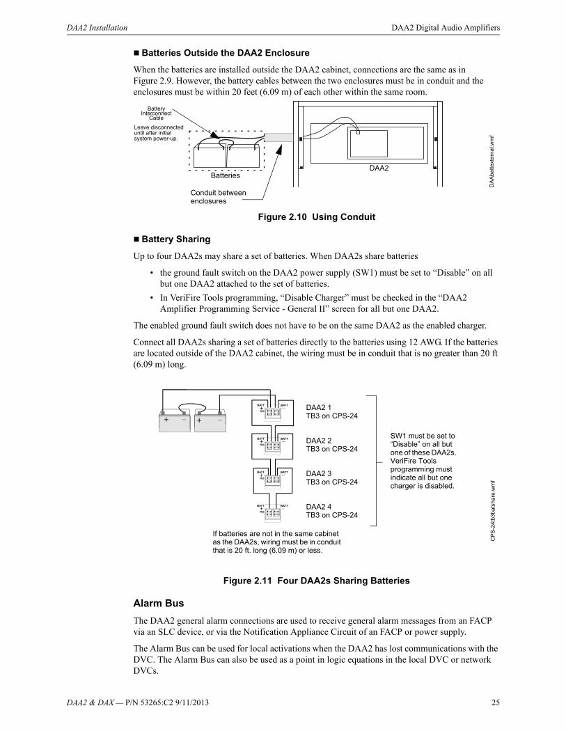
Batteries Outside the DAA2 Enclosure
When the batteries are installed outside the DAA2 cabinet, connections are the same as in Figure 2.9. However, the battery cables between the two enclosures must be in conduit and the enclosures must be within 20 feet (6.09 m) of each other within the same room.
Figure 2.10 Using Conduit
Battery Sharing
Up to four DAA2s may share a set of batteries. When DAA2s share batteries
• the ground fault switch on the DAA2 power supply (SW1) must be set to “Disable” on all but one DAA2 attached to the set of batteries.
• In VeriFire Tools programming, “Disable Charger” must be checked in the “DAA2 Amplifier Programming Service - General II” screen for all but one DAA2.
The enabled ground fault switch does not have to be on the same DAA2 as the enabled charger.
Connect all DAA2s sharing a set of batteries directly to the batteries using 12 AWG. If the batteries are located outside of the DAA2 cabinet, the wiring must be in conduit that is no greater than 20 ft (6.09 m) long.
Figure 2.11 Four DAA2s Sharing Batteries
Alarm Bus
The DAA2 general alarm connections are used to receive general alarm messages from an FACP via an SLC device, or via the Notification Appliance Circuit of an FACP or power supply.
The Alarm Bus can be used for local activations when the DAA2 has lost communications with the DVC. The Alarm Bus can also be used as a point in logic equations in the local DVC or network DVCs.
DA
Ab
atte
xter
na
l.wm
f
DAA2Batteries
Conduit between enclosures
Battery Interconnect
Cable
Leave disconnected until after initial system power-up.
If batteries are not in the same cabinet as the DAA2s, wiring must be in conduit that is 20 ft. long (6.09 m) or less.
CP
S-2
4tb
3ba
tsh
are
.wm
f
DAA2 1 TB3 on CPS-24
SW1 must be set to “Disable” on all but one of these DAA2s. VeriFire Tools programming must indicate all but one charger is disabled.
DAA2 2 TB3 on CPS-24
DAA2 3 TB3 on CPS-24
DAA2 4 TB3 on CPS-24

26 DAA2 & DAX — P/N 53265:C2 9/11/2013
DAA2 Digital Audio Amplifiers DAA2 Installation
Figure 2.12 Alarm Bus Connections to FCM-1
Figure 2.13 Alarm Bus Connections to NAC
Refer to the SLC manual and specific panel or power supply manual for more information.
FCM-1*
ALARM Bus to next DAA2ELR-47K, 1/2 watt resistor
DAA2
FZ
MF
CM
tpH
a.w
mf
TB4 TB4
14-18 AWG twisted-pair recommended
Program the control module at the FACP with an appropriate alarm Type ID per the FACP manual.
Alarm Bus requires 16VDC at 20mA across the terminals to activate. Nominal 24 VDC.
To Power Supply
+- SLC
from FACP
SLC to next device
+-
+ -
+
-*If the SLC device does not match the one in this figure, refer to the SLC manual appendix, which contains wiring conver-sion charts for type V and type H modules.
ALM REF ALM REFOUTIN ALM REF ALM REFOUTIN
NAC CircuitA -
A +
B +
B -
ALARM Bus to next DAA2
DA
AB
RD
tb4.
wm
fDAA2
TB4 TB4
ELR per panel or power supply manual.
14-18 AWG twisted-pair recommended
Listed compatible panel or power supply with onboard NAC circuits.
Alarm Bus requires 16VDC at 20mA across the
terminals to activate. Nominal 24VDC.
ALM REF ALM REFOUTIN ALM REF ALM REFOUTIN

DAA2 & DAX — P/N 53265:C2 9/11/2013 27
DAA2 Installation DAA2 Digital Audio Amplifiers
Digital Audio Ports A and B, Wire Connections
Digital Audio Ports A and B (DAP A and DAP B) allow digital communication with the DVC over the Digital Audio Loop (DAL); Amplifier programming from the DVC; control, audio, trouble, address and firefighter telephone data; and live voice paging can be communicated through these ports. They may also act as repeaters, in that what is received at one port is transmitted out the other. Events generated at the DAA2 will be transmitted out both ports.
Figure 2.14 Wire the DAA2 Digital Audio Loop Connections
Digital Audio Ports A and B, Fiber and Wire/Fiber Connections
DAA2 boards are wire, but may be converted partially or fully to fiber boards with the use of fiber option modules DS-FM and DS-SFM. (Refer to Section 5.3.1, “DAA2 Installation”, on page 77 for information on installing fiber option modules.) The fiber, or wire/fiber cabling between these ports provides a Digital Audio Loop (DAL) for programming; alarm, control, trouble, automatic audio messages, address and firefighter telephone data; and live voice paging communications.
Figure 2.15 illustrates an example of how a DAL can be formed using mixed wire and fiber connectors.
DVC
Refer to the Wiring Guide, p/n 52916ADD, for acceptable wire types and associated distances between ports.Do not splice a cable. Splicing will degrade the signal, and the recommended distance will no longer apply.
DAPA, TB3
DAPB, TB2REF
DAA2 #1
Optional Class A (Style 7) returnConnections are polarity sensitive.Connections are port sensitive. Always connect Port A to Port B.
DAA2 #2 DAA2 #32
TB2 TB2 TB2TB3 TB3 TB3
DAP AREF
DAP AREF
DAP AREF
DAP B
REFDAP B
REFDAP B
REF
REF
NOTE: Digital Audio Ports A and B must be wired in Class B (Style 4) or Class A (Style 7) configuration. Do not wire them in bus configuration.
NOTE: Class B (Style 4) configuration must be installed in accordance with the requirements for survivability from attack by fire in the National Fire Alarm Code, NFPA 72.
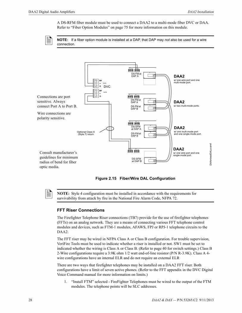
28 DAA2 & DAX — P/N 53265:C2 9/11/2013
DAA2 Digital Audio Amplifiers DAA2 Installation
A DS-RFM fiber module must be used to connect a DAA2 to a multi-mode fiber DVC or DAA. Refer to “Fiber Option Modules” on page 75 for more information on this module.
Figure 2.15 Fiber/Wire DAL Configuration
FFT Riser Connections
The Firefighter Telephone Riser connections (TB7) provide for the use of firefighter telephones (FFTs) on an analog network. They are a means of connecting various FFT telephone control modules and devices, such as FTM-1 modules, AFAWS, FPJ or RPJ-1 telephone circuits to the DAA2.
The FFT riser may be wired in NFPA Class A or Class B configuration. For trouble supervision, VeriFire Tools must be used to indicate whether a riser is installed or not. SW1 must be set to indicated whether the wiring is Class A or Class B. (Refer to page 40 for switch settings.) Class B 2-Wire configurations require a 3.9K ohm 1/2 watt end-of-line resistor (P/N R-3.9K). Class A 4-wire configurations have an internal ELR and do not require an external ELR
There are two ways that firefighter telephones may be installed on a DAA2 FFT riser. Both configurations have a limit of seven active phones. (Refer to the FFT appendix in the DVC Digital Voice Command manual for more information on limits.)
1. “Install FTM” selected - FireFighter Telephones must be wired to the output of the FTM modules. The telephone points will be SLC addresses.
NOTE: If a fiber option module is installed at a DAP, that DAP may not also be used for a wire connection.
DA
Am
ixed
DA
La.w
mf
Optional Class X (Style 7) return
DAA2w/ one wire port and one multi-mode port.
Consult manufacturer’s guidelines for minimum radius of bend for fiber optic media.
DAA2w/ two multi-mode ports.
Connections are port sensitive. Always connect Port A to Port B.
Wire connections are polarity sensitive.
DAA2w/ one multi-mode port and one single-mode port.
DAA2w/ one wire port and one single-mode port.
DVC
DS-FM at DAP A
DS-SFM at DAP B
DS-SFM at DAP A
DS-FM at DAP B
DS-FM at DAP A
DS-FM at DAP B
NOTE: Style 4 configuration must be installed in accordance with the requirements for survivability from attack by fire in the National Fire Alarm Code, NFPA 72.
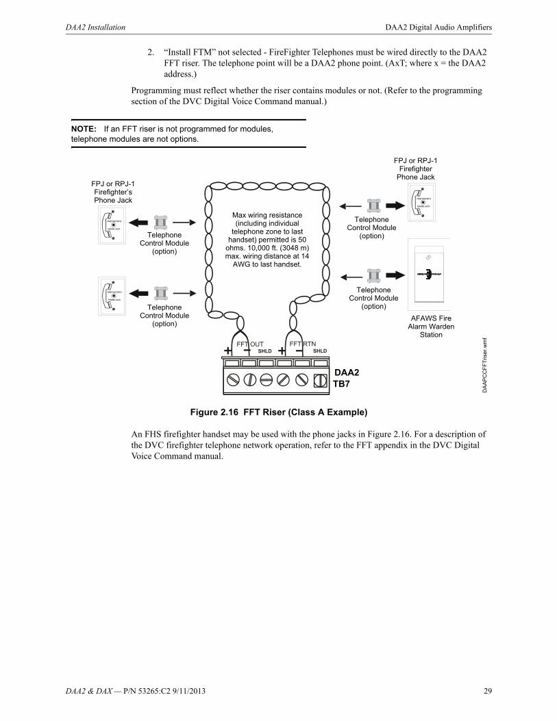
DAA2 & DAX — P/N 53265:C2 9/11/2013 29
DAA2 Installation DAA2 Digital Audio Amplifiers
2. “Install FTM” not selected - FireFighter Telephones must be wired directly to the DAA2 FFT riser. The telephone point will be a DAA2 phone point. (AxT; where x = the DAA2 address.)
Programming must reflect whether the riser contains modules or not. (Refer to the programming section of the DVC Digital Voice Command manual.)
Figure 2.16 FFT Riser (Class A Example)
An FHS firefighter handset may be used with the phone jacks in Figure 2.16. For a description of the DVC firefighter telephone network operation, refer to the FFT appendix in the DVC Digital Voice Command manual.
Telephone Control Module
(option)
DA
AP
CC
FF
Tris
er.w
mf
DAA2
AFAWS Fire Alarm Warden
Station
TB7
Max wiring resistance (including individual
telephone zone to last handset) permitted is 50
ohms. 10,000 ft. (3048 m) max. wiring distance at 14
AWG to last handset.
Telephone Control Module
(option)
Telephone Control Module
(option)
NOTE: If an FFT riser is not programmed for modules, telephone modules are not options.
FPJ or RPJ-1 Firefighter
Phone JackFPJ or RPJ-1 Firefighter’s Phone Jack
Telephone Control Module
(option)
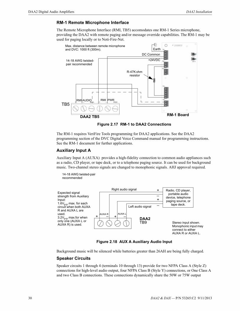
30 DAA2 & DAX — P/N 53265:C2 9/11/2013
DAA2 Digital Audio Amplifiers DAA2 Installation
RM-1 Remote Microphone Interface
The Remote Microphone Interface (RMI, TB5) accomodates one RM-1 Series microphone, providing the DAA2 with remote paging and/or message override capabilities. The RM-1 may be used for paging locally or to Noti-Fire-Net.
Figure 2.17 RM-1 to DAA2 Connections
The RM-1 requires VeriFire Tools programming for DAA2 applications. See the DAA2 programming section of the DVC Digital Voice Command manual for programming instructions. See the RM-1 document for further applications.
Auxiliary Input A
Auxiliary Input A (AUXA) provides a high-fidelity connection to common audio appliances such as a radio, CD player, or tape deck, or to a telephone paging source. It can be used for background music. Two-channel stereo signals are changed to monophonic signals. AHJ approval required.
Figure 2.18 AUX A Auxiliary Audio Input
Background music will be silenced while batteries greater than 26AH are being fully charged.
Speaker Circuits
Speaker circuits 1 through 4 (terminals 10 through 13) provide for two NFPA Class A (Style Z) connections for high-level audio output, four NFPA Class B (Style Y) connections, or One Class A and two Class B connections. These connections dynamically share the 50W or 75W output
DAA2 TB5 RM-1 Board
+24VDC
DC Common
R-47K ohm resistor
14-18 AWG twisted-pair recommended
Max. distance between remote microphone and DVC: 1000 ft (300m). Earth
Radio, CD player, portable audio
device, telephone paging source, or
tape deck.
_+
_+
Left audio signal
Right audio signal
DAA2TB9
Expected signal strength from Auxiliary Input:1.6Vp-p max. for each circuit when both AUXA R and AUXA L are used.3.2Vp-p max.for when only one (AUXA L or AUXA R) is used.
Stereo input shown. Monophonic input may connect to either AUXA R or AUXA L.
14-18 AWG twisted-pair recommended
AUXA R AUXA L_+ _+
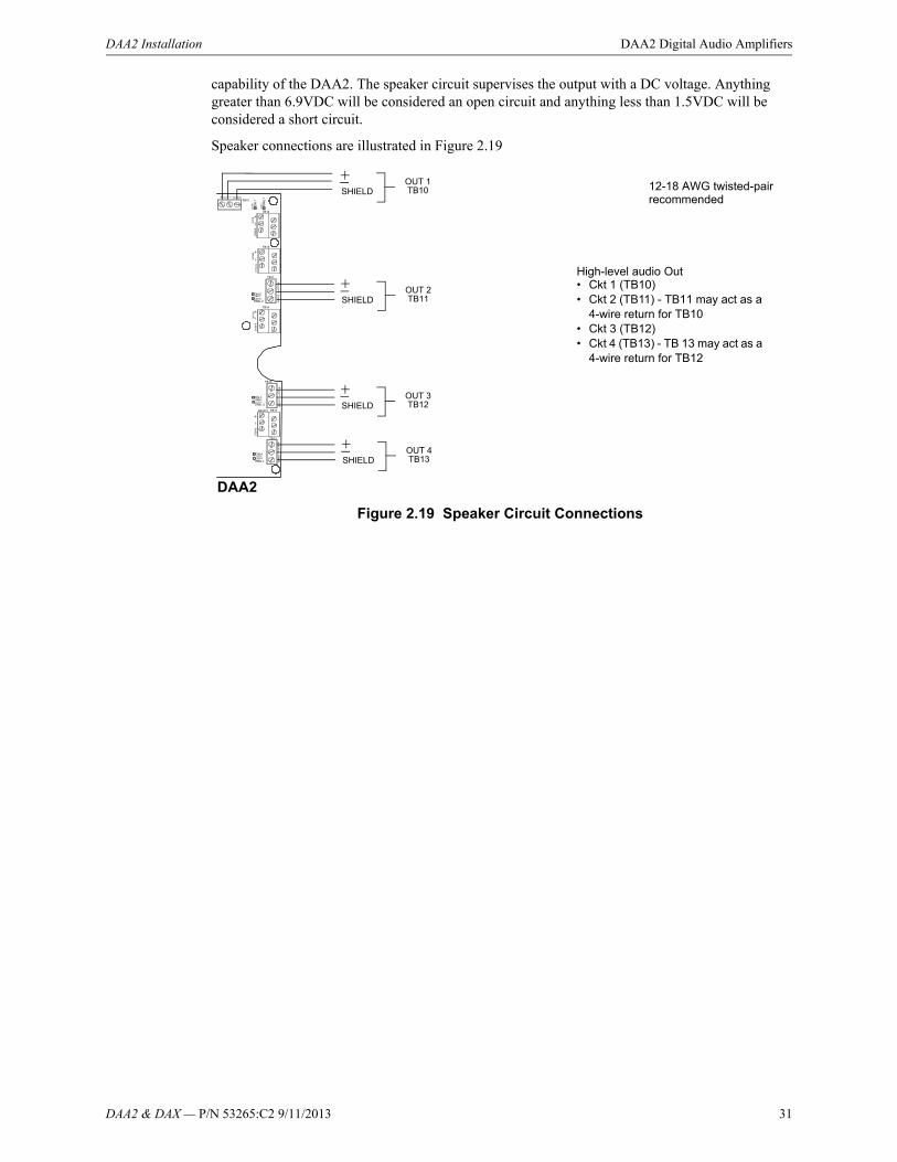
DAA2 & DAX — P/N 53265:C2 9/11/2013 31
DAA2 Installation DAA2 Digital Audio Amplifiers
capability of the DAA2. The speaker circuit supervises the output with a DC voltage. Anything greater than 6.9VDC will be considered an open circuit and anything less than 1.5VDC will be considered a short circuit.
Speaker connections are illustrated in Figure 2.19
High-level audio Out• Ckt 1 (TB10)• Ckt 2 (TB11) - TB11 may act as a
4-wire return for TB10• Ckt 3 (TB12)• Ckt 4 (TB13) - TB 13 may act as a
4-wire return for TB12
12-18 AWG twisted-pair recommended
SHIELDOUT 1TB10
SHIELDOUT 2TB11
SHIELDOUT 3TB12
SHIELDOUT 4TB13
Figure 2.19 Speaker Circuit Connections
DAA2

32 DAA2 & DAX — P/N 53265:C2 9/11/2013
DAA2 Digital Audio Amplifiers DAA2 Installation
In Normal (NAC) Mode
When a DAA2’s Riser Mode is programmed NORMAL (NAC) (refer to the DVC Digital Voice Command manual for programming description), the amplified signal from the DAA2 may be connected directly to speakers. Following are illustrations of Class A and Class B configurations (Figure 2.20).
Figure 2.20 Normal Riser Mode Class Configurations
Two DAA2 Class A (Style Z) Circuits Four DAA2 Class B (Style Y) Circuits
20k ohm end-of-line resistor,p/n ELR-20K
High-level Return
High-level Out
R-10K
R-10K
High-level Return
High-level Out
20k ohm end-of-line resistor,p/n ELR-20K
20k ohm end-of-line resistor,p/n ELR-20K
20k ohm end-of-line resistor,p/n ELR-20K
High Level Return
R-10K
High-level Out
20k ohm end-of-line resistor,p/n ELR-20K
20k ohm end-of-line resistor,p/n ELR-20K
One DAA2 Class A Circuit, Two Class B Circuits
TB10
TB11
TB12
TB13
SHIELD
OUT 1
SHIELD
OUT 2
SHIELD
OUT 3
SHIELD
OUT 4
TB10
TB11
TB12
TB13
SHIELD
OUT 1
SHIELD
OUT 2
SHIELD
OUT 3
SHIELD
OUT 4
TB10
TB11
TB12
TB13
SHIELD
OUT 1
SHIELD
OUT 2
SHIELD
OUT 3
SHIELD
OUT 4

DAA2 & DAX — P/N 53265:C2 9/11/2013 33
DAA2 Installation DAA2 Digital Audio Amplifiers
In Riser Mode to Additional Amplifiers
When a DAA2’s Riser Mode is programmed RISER MODE TO ADDITIONAL AMPLIFIERS (refer to the DVC Digital Voice Command manual for programming), the amplified signal from the DAA2 may be connected to an audio coupling transformer (ACT-25 for 25V amplifiers, ACT-70 for 70V amplifiers) to drive additional AA-Series amplifiers. This mode provides a 200 Hz supervisory tone required by analog amplifiers.
Figure 2.21 DAA2 Riser Mode to Additional Amplifiers
Refer to the ACT-25 or ACT-70 installation document for more information.
In Riser Mode to Control Modules
When a DAA2’s Riser Mode is programmed RISER MODE TO CONTROL MODULES (refer to the DVC Digital Voice Command manual for programming), the amplified signal from the DAA2 may be routed to multiple speaker circuits using SLC control modules.
The control module must disable the power supply monitoring to prevent acting as a load on the supervision voltage. For V-type control modules, this requires a resistor cut under the label. For H-type modules, a jumper must be removed under the label. For XP6-C modules, a jumper must be removed for each address.
To prevent unnecessarily charging and discharging the supervision voltage of a control module and the supervision voltage of the DAA2, connect the amplifier (+) to the power supply (-) on the control module. Connect the amplifier (-) to the control module power supply (+) input.
AA-100/AA-100Eor
AA-120/AA-120EAA-30/AA-30E
Audio Coupling Transformer
DAA2
Low-level Audio Low-level Audio
High-level AudioHigh-level AudioTo other audio coupling transformers or 20k ELR (Class B)
Optional 4-wire return from last audio coupling transformer
TB1
P1 P1
TB1
TB10
TB11
10k ELR (Class A)
DA
A2
AC
T.w
mf
AudioCoupling
Transformer
Up to 7 low-level
inputs
Up to 7 low-level
inputs

34 DAA2 & DAX — P/N 53265:C2 9/11/2013
DAA2 Digital Audio Amplifiers DAA2 Installation
Do not use background music in this mode. The DAA2 will provide speaker circuit supervision only when idle.
Two separate risers are a possible configuration when using a DAA2 with a BDA set for a second channel, in a second group.
In Riser Mode to RSM/AIM Series Canadian Room Isolator Modules
When a DAA2’s Riser Mode is programmed RISER MODE TO RSM/AIM SERIES MODULES (refer to the DVC Digital Voice Command manual for programming), the amplified signal from the DAA2 is routed to RSM-1A or AIM-1A room isolator modules.
AIM-1A - Provides isolation to a separate circuit on an audio riser. A short circuit on an AIM-1A speaker circuit will not disable other speaker circuits on the riser.
DAA2 TB10
DA
A2
spkr
cktr
ise
r.w
mf
20k ELR (Class B)
SLC Control Module
SLC Control ModuleSLC Control Module
Figure 2.22 DAA2 Riser Mode to Control Modules, Single Riser
DAA2
TB10
DA
A2
spkr
cktr
iser
2.w
mf
20k ELR (Class B)
XPC-6 SLC Control Module
Figure 2.23 DAA2 Riser Mode to Control Modules, Two Separate Risers
20k ELR (Class B)
TB12
XPC-6 SLC Control Module
Circuits 1 and 3
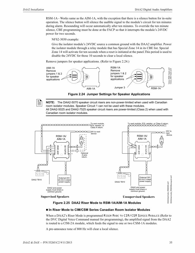
DAA2 & DAX — P/N 53265:C2 9/11/2013 35
DAA2 Installation DAA2 Digital Audio Amplifiers
RSM-1A - Works same as the AIM-1A, with the exception that there is a silence button for in-suite operation. The silence button will silence the audible signal to the module’s circuit for ten minutes during alarm. Resounding will occur automatically after ten minutes. To override the ten minute silence, CBE programming must be done at the FACP so that it interrupts the module’s 24VDC power for two seconds.
NFS2-3030 example:
Give the isolator module’s 24VDC source a common ground with the DAA2 amplifier. Power the isolator module through a relay module that has Special Zone 14 in its CBE list. Special Zone 14 will activate for ten seconds when a reset is initiated at the panel.This period is used to disable the 24VDC for those 10 seconds to clear a local silence.
Remove jumpers for speaker applications. (Refer to Figure 2.24.)
Figure 2.24 Jumper Settings for Speaker Applications
In Riser Mode to CIM/CSM Series Canadian Room Isolator Modules
When a DAA2’s Riser Mode is programmed RISER MODE TO CIM/CSM SERIES MODULES (Refer to the DVC Digital Voice Command manual for programming), the amplified signal from the DAA2 is routed to a CIM-2A module, which feeds the signal to one or two CSM-1A modules.
A pre-announce tone of 800 Hz will clear a local silence.
AIM-1ARemove jumpers 1 & 2 for speaker applications
RSM-1ARemove jumpers 1 & 2 for speaker applications
Jumper 3
Vo
ice_
AIM
-1ba
ck.w
mf
Vo
ice_
RS
M-1
back
.wm
f
AIM-1A RSM-1A
NOTE: The DAA2-5070 speaker circuit risers are non-power-limited when used with Canadian room isolator modules. Speaker Circuit 1 can not be used with these modules.All DAA2-5025 and DAA2-7525 speaker circuit risers are power-limited (Class 2) when used with Canadian room isolator modules.
RSM-1A/AIM-1A
RSM-1A/AIM-1A
External 24V UL/ULC Listed power supply
DAA2 TB10
DAA2 and power supply must share a
common ground.
DAA2 and power supply must share a
common ground.
External 24V UL/ULC Listed power supply
Optional 4-wire return.
Supervised Speakers Unsupervised Speakers
Figure 2.25 DAA2 Riser Mode to RSM-1A/AIM-1A Modules
24V to next device
To next module, EOL resistor, orClass A return.
To next module, EOL resistor, or Class A return.
24V to next device
DA
A2r
iser
mod
e_R
SM
AIM
.wm
f
DA
A2r
iser
mo
de_R
SM
AIM
unsu
pvd.
wm
f
DAA2 TB10

36 DAA2 & DAX — P/N 53265:C2 9/11/2013
DAA2 Digital Audio Amplifiers DAA2 Installation
Do not use background music in this mode. The DAA2 will provide speaker circuit supervision only when idle.
Speaker Backup Circuits - TB1, TB14, TB15, TB16
The DAA2 supports one-to-one or one-to-many backup amplifier applications. A BDA-25/70V backup amplifier may be used in a one-to-one backup application. Refer to “BDA Backup Digital Amplifiers” on page 67 for information on the BDA-25/70V amplifier. Each DAA2 must be designated a primary or backup amplifier through VeriFire Tools programming. The speaker wiring from backup to primary is unsupervised when the backup amplifier is not active; therefore the backup and primary amplifiers must be in the same enclosure, or in conduit within the same room.
Each backup terminal block contains two sets of terminals. One set may be used for “Backup In” applications, the other set for “Backup Through” applications..
NOTE: The DAA2-5070 speaker circuit risers are non power-limited when used with Canadian room isolator modules. Speaker Circuit 1 can not be used with these modules.All DAA2-5025 and DAA2-7525 speaker circuit risers are power-limited (Class 2) when used with Canadian room isolator modules.
Figure 2.26 DAA2 Riser Mode to CIM-2A/CSM-1A Modules
CIM-2ADAA2
To next module, EOL resistor, orClass A return.
CSM-1A
CSM-1A
DA
A2r
isrm
ode
_CIM
CS
M.w
mf
NOTE: In Style 4 wiring arrangements of the DAL (digital audio loop), it is recommended that the backup amplifier be located closer to the DVC than the primary DAA2 amplifiers on the DAL.
Each DAA2 acts as a repeater for the digital audio signal. If a primary amplifier falls off-line, the backup will not receive the signal if it is further down the DAL chain.
DVC
DVC
DAA2 Backup
DAA2 Backup
DAA2 Primary
DAA2 Primary
Recommended
Not Recommended

DAA2 & DAX — P/N 53265:C2 9/11/2013 37
DAA2 Installation DAA2 Digital Audio Amplifiers
One-to-One Backup Using BDA-25/70V
Figure 2.27 shows the installation of a BDA-25/70V backup digital amplifier onto the primary amplifier. Should the primary amplifier fail, all its messages will still be played by the BDA as programmed.
One-to-One or One-to-Many Backup Using BKUP Terminal Blocks
The BKUP1through BKUP4 terminals on the DAA2 may be used to connect a backup amplifier to one or more primary amplifiers.
One backup amplifier may be used to back up as many as 31 primary amplifiers. All primary amplifiers backed by the same backup amplifier must each be wired in the same style or combination of styles; for example, all wired Class A, or all wired Class B, or all wired with one Class A and two Class B circuits.
1. Attach four standoffs (p.n 42222) at locations indicated.
2. Align BDA over standoffs. Attach with four screws.
3. Attach power harnesses (included with BDA): Refer to Figure 4.4 on page 70
Power Harness Connections
BDA
DAA2
• J1 on BDA to J6 on DAA2• J2 on BDA to J5 on DAA2
Power Harness Connections
J2 J1J5 J6
Figure 2.27 One-to-one Backup Using BDA-25/70V
NOTE: Each backup terminal block contains two sets of terminals. One set may be used for “Backup In” applications, the other set for “Backup Through” applications.

38 DAA2 & DAX — P/N 53265:C2 9/11/2013
DAA2 Digital Audio Amplifiers DAA2 Installation
A backup amplifier can support one failed primary amplifier at a time. Should another primary amplifier also fail, depending on load, the backup amplifier may also fail, generating an AMPLIFIER LIMIT trouble until the load is reduced or reset.
Figure 2.28 One-to-one or One-to-Many Backup Using BKUP Terminal Blocks
Wiring Fault Testing
Test wire-to-wire faults with 0 (zero) ohm impedance.
DAP A+DAP A-REF A
TB2
TB3
DAP B+
DAP B-REF B
DVC
Speaker Circuit(OUT1, TB10)
To next primary amplifier for one-to-many backup*
DAA2 BACKUP
DAA2 PRIMARY
Speaker CircuitOUT2, TB11
Optional Class A Return
Digital Signal from DVC
BKUP1TB 14
BKUP2TB15
BKUP3TB16
Speaker CircuitOUT3, TB12
BKUP4TB17
Speaker CircuitOUT4, TB13
DAPA DAPBDAPA DAPB
To next primary amplifier for one-to-many backup*
To next primary amplifier for one-to-many backup*
To next primary amplifier for one-to-many backup*
*Note: No end-of-line resistor is necessary at the last primary amplifier backup terminal.

DAA2 & DAX — P/N 53265:C2 9/11/2013 39
DAA2 Installation DAA2 Digital Audio Amplifiers
UL Power-limited (Class 2) Wiring Requirements
Power-limited and non-power-limited circuit wiring must remain separated in the cabinet. All power-limited circuit wiring must remain at least 0.25 inches (6.35 mm) from any non-power-limited circuit wiring. All power-limited and non-power-limited circuit wiring must enter and exit the cabinet through different knockouts and/or conduits.
Figure 2.29 Typical Backbox Wiring
Figure 2.30 below illustrates power-limited wiring specific to a DAA2-5070 when it is used with any Canadian room isolator module.
Figure 2.30 DAA2-5070-specific Wiring with Canadian Room Isolator Modules
Power-limited (Class 2) circuits
Non-power-limited circuits
DA
AU
Lwiri
ng.
wm
f
Non-power-limited circuits
Non-power-limited circuits
Power-limited (Class 2) circuits
to Canadian room isolator
modules
to Canadian room isolator
modules
DAA2-5070
TB10 (Circuit 1) can not be used with Canadian room isolator modules
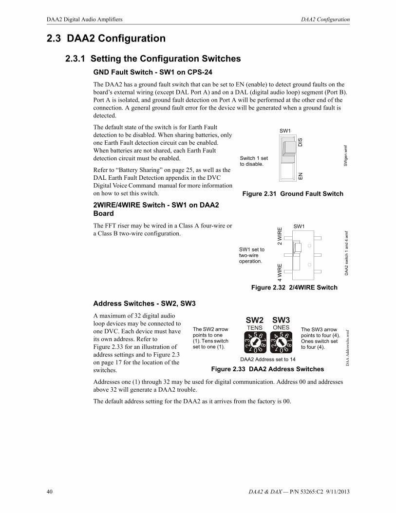
40 DAA2 & DAX — P/N 53265:C2 9/11/2013
DAA2 Digital Audio Amplifiers DAA2 Configuration
2.3 DAA2 Configuration
2.3.1 Setting the Configuration Switches
GND Fault Switch - SW1 on CPS-24
The DAA2 has a ground fault switch that can be set to EN (enable) to detect ground faults on the board’s external wiring (except DAL Port A) and on a DAL (digital audio loop) segment (Port B). Port A is isolated, and ground fault detection on Port A will be performed at the other end of the connection. A general ground fault error for the device will be generated when a ground fault is detected.
The default state of the switch is for Earth Fault detection to be disabled. When sharing batteries, only one Earth Fault detection circuit can be enabled. When batteries are not shared, each Earth Fault detection circuit must be enabled.
Refer to “Battery Sharing” on page 25, as well as the DAL Earth Fault Detection appendix in the DVC Digital Voice Command manual for more information on how to set this switch.
2WIRE/4WIRE Switch - SW1 on DAA2 Board
The FFT riser may be wired in a Class A four-wire or a Class B two-wire configuration.
Address Switches - SW2, SW3
A maximum of 32 digital audio loop devices may be connected to one DVC. Each device must have its own address. Refer to Figure 2.33 for an illustration of address settings and to Figure 2.3 on page 17 for the location of the switches.
Addresses one (1) through 32 may be used for digital communication. Address 00 and addresses above 32 will generate a DAA2 trouble.
The default address setting for the DAA2 as it arrives from the factory is 00.
Figure 2.31 Ground Fault Switch
SW1
Switch 1 set to disable. S
Wge
n.w
mfD
ISE
N
Figure 2.32 2/4WIRE Switch
SW1
SW1 set to two-wire operation.
DA
A2
sw
itch
1 a
nd
4.w
mf
4 W
IRE
2 W
IRE
Figure 2.33 DAA2 Address Switches
DAA2 Address set to 14
The SW2 arrow points to one (1). Tens switch set to one (1).
The SW3 arrow points to four (4). Ones switch set to four (4).
DA
A A
ddrs
wtc
hs.w
mf
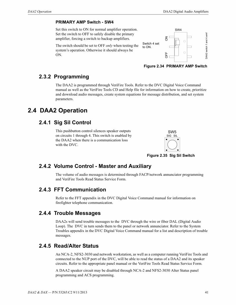
DAA2 & DAX — P/N 53265:C2 9/11/2013 41
DAA2 Operation DAA2 Digital Audio Amplifiers
PRIMARY AMP Switch - SW4
Set this switch to ON for normal amplifier operation. Set the switch to OFF to safely disable the primary amplifier, forcing a switch to backup amplifiers.
The switch should be set to OFF only when testing the system’s operation. Otherwise it should always be ON.
2.3.2 Programming
The DAA2 is programmed through VeriFire Tools. Refer to the DVC Digital Voice Command manual as well as the VeriFire Tools CD and Help file for information on how to create, prioritize and download audio messages, create system equations for message distribution, and set system parameters.
2.4 DAA2 Operation
2.4.1 Sig Sil Control
This pushbutton control silences speaker outputs on circuits 1 through 4. This switch is enabled by the DAA2 when there is a communication loss with the DVC.
2.4.2 Volume Control - Master and Auxiliary
The volume of audio messages is determined through FACP/network annunciator programming and VeriFire Tools Read Status Service Form.
2.4.3 FFT Communication
Refer to the FFT appendix in the DVC Digital Voice Command manual for information on firefighter telephone communication.
2.4.4 Trouble Messages
DAA2s will send trouble messages to the DVC through the wire or fiber DAL (Digital Audio Loop). The DVC in turn sends them to the panel or network annunciator. Refer to the System Troubles appendix in the DVC Digital Voice Command manual for a list and description of trouble messages.
2.4.5 Read/Alter Status
An NCA-2, NFS2-3030 and network workstation, as well as a computer running VeriFire Tools and connected to the NUP port of the DVC, will be able to read the status of a DAA2 and its speaker circuits. Refer to the appropriate panel manual or the VeriFire Tools Read Status Service Form.
A DAA2 speaker circuit may be disabled through NCA-2 and NFS2-3030 Alter Status panel programming and ACS programming.
Figure 2.34 PRIMARY AMP Switch
SW4
Switch 4 set to ON.
DA
A2
switc
h 1
and
4.w
mf
OF
F
O
N
Figure 2.35 Sig Sil Switch
SW5SIG SIL
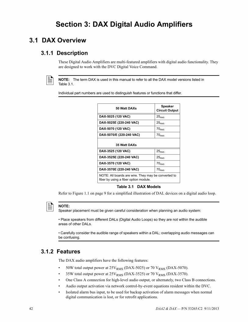
42 DAA2 & DAX — P/N 53265:C2 9/11/2013
Section 3: DAX Digital Audio Amplifiers
3.1 DAX Overview
3.1.1 Description
These Digital Audio Amplifiers are multi-featured amplifiers with digital audio functionality. They are designed to work with the DVC Digital Voice Command.
Refer to Figure 1.1 on page 9 for a simplified illustration of DAL devices on a digital audio loop.
3.1.2 Features
The DAX audio amplifiers have the following features:
• 50W total output power at 25VRMS (DAX-5025) or 70 VRMS (DAX-5070).
• 35W total output power at 25VRMS (DAX-3525) or 70 VRMS (DAX-3570).
• One Class A connection for high-level audio output, or alternately, two Class B connections.
• Audio output activation via network control-by-event equations resident within the DVC.
• Isolated alarm bus input, to be used for backup activation of alarm messages when normal digital communication is lost, or for retrofit applications.
NOTE: The term DAX is used in this manual to refer to all the DAX model versions listed in Table 3.1.
Individual part numbers are used to distinguish features or functions that differ.
50 Watt DAXsSpeaker
Circuit Output
DAX-5025 (120 VAC) 25RMS
DAX-5025E (220-240 VAC) 25RMS
DAX-5070 (120 VAC) 70RMS
DAX-5070/E (220-240 VAC) 70RMS
35 Watt DAXs
DAX-3525 (120 VAC) 25RMS
DAX-3525E (220-240 VAC) 25RMS
DAX-3570 (120 VAC) 70RMS
DAX-3570E (220-240 VAC) 70RMS
NOTE: All boards are wire. They may be converted to fiber by using a fiber option module.
Table 3.1 DAX Models
NOTE:Speaker placement must be given careful consideration when planning an audio system:
• Place speakers from different DALs (Digital Audio Loops) so they are not within the audible areas of other DALs.
• Carefully consider the audible range of speakers within a DAL; overlapping audio messages can be confusing.

DAA2 & DAX — P/N 53265:C2 9/11/2013 43
DAX Overview DAX Digital Audio Amplifiers
• Amplifies one channel of digital audio and distributes it on up to two outputs (50W maximum for DAX-50, 35W maximum for DAX-35).
• Uploads and downloads via the DVC.
• Up to 106 seconds of digital message storage for use during communication loss (emergency tone, non-emergency tone, and FFT busy tone) from the VeriFire Tools message library, or created by the installer.
• Battery charger (35 watt DAXs only).
• Backup amplifier options.
• Programmable through VeriFire Tools.
• Meets UL THD Distortion requirements for 500 Hz to 4 KHz bandwidth.Meets ULC THD Distortion requirements for 400 Hz to 4 KHz bandwidth.
3.1.3 Specifications
AC Power - TB7
120 VAC, 50/60 Hz input.*
220-240 VAC, 50/60 Hz input.*
*Maximum AC draw varies by DAX model. These draws are given in Appendix A, “AC Current Draw Calculations”, along with a worksheet to determine the actual AC draw.
Recommended wiring: 12-14 AWG (1.6mm O.D.) with 600 VAC insulation.
Battery Connections - TB8, TB9
Supplied cable connections to batteries for CAB-4. For battery sharing, use 12 AWG either in the same cabinet or in conduit for no more than 20 ft (6.09 m).
Battery Charger (DAX-35 Boards Only)
Current-limited sealed lead acid battery charger which charges two 12 volt batteries in series, up to 26AH.
Charger voltage: 27.6 VDC.
For battery calculation worksheet and standby operating times, refer to Appendix B, “Battery Calculations”, on page 84.
Utilizes wire sizes 12-18 AWG.
Battery Fuse (F2) 10A.
Wire Digital Audio Ports A and B - TB1, TB2
Refer to the Wiring Guide, p/n 52916ADD, for acceptable wire types.
EIA-485 format.
Power-limited (Class 2).
Refer to Section 5, “Fiber Option Modules”, on page 75 for fiber connections. When a fiber option module is mounted on a DAX, it disables the corresponding wire terminals. TB1 (Digital Audio Port A) is disabled when a fiber option board is connected at J2. TB2 (Digital Audio Port B) is disabled when a fiber option board is connected at J3.
Alarm Bus - TB3
Power-limited (Class 2) and supervised by source.
Recommended wiring: 14-18 AWG twisted-pair.
Requires 16 VDC @ 20mA across the terminals to activate. Nominal 24 VDC.
NOTE: 50 Watt DAX boards do not have an onboard battery charger. A UL 864 listed power supply rated for the battery requirements of the specific application is suitable for charging purposes.
44 DAA2 & DAX — P/N 53265:C2 9/11/2013
DAX Digital Audio Amplifiers DAX Overview
Speaker Circuits - TB4 and TB5
Power-limited (Class 2) outputs*
* Exception: A DAX-3570 and DAX-5070 speaker circuit used with any Canadian Room Isolator modules is non-power-limited.
DAX-5025/70 - Each circuit rated up to 50 watts.**
DAX-3525/70 - Each circuit rated up to 35 watts.**
**Total wattage may vary. Refer to “BDA Backup Digital Amplifiers” on page 67 for configurations.
Supervision determined by programming.
25VRMS - DAX-5025/DAX-3525 speaker circuits, 70VRMS - DAX-5070/DAX-3570 speaker circuits.
Recommended wiring: 12-18 AWG twisted-pair (shielded recommended).
Class B or Class A:
Class B requires 20k end-of-line resistors (included, P/N ELR-20K).
Class A requires 10k end-of-line resistors (included, P/N R-10K) on the return.
Backup from Alternate Amplifier - TB10 and TB11High-level audio input.
• 25VRMS (DAX-5025 and DAX-3525)
• 70VRMS (DAX-5070 and DAX-3570)
Recommended wiring: 14-18 AWG twisted-pair (shielded recommended).
• 25V (DAX-5025 and DAX-3525)
• 70V (DAX-5070 and DAX-3570)
Supervision:
• Not supervised when inactive. Supervised by backup source when active.
• Must be in the same room or enclosure.
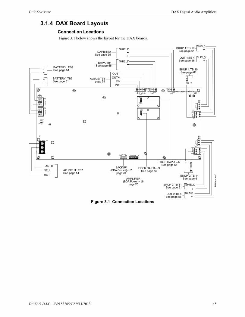
DAA2 & DAX — P/N 53265:C2 9/11/2013 45
DAX Overview DAX Digital Audio Amplifiers
3.1.4 DAX Board Layouts
Connection Locations Figure 3.1 below shows the layout for the DAX boards.
Figure 3.1 Connection Locations
HOT
NEU
EARTH
AC INPUT: TB7See page 51
- BATTERY: TB8See page 51-
++
OUT-
IN-OUT+
IN+
ALBUS:TB3page 54
DAPB:TB2See page 55 +
-
+
SHIELD-
SHIELD
+BKUP 1:TB 10See page 61
BACKUP(BDA Control) - J7
page 70
DA
Xbr
da.w
mf
FIBER DAP B - J3See page 56
SHIELD
+OUT 1:TB 4
See page 56
SH
IEL
D
+
SHIELD
+
SHIELD
+
SH
IEL
D
+
SHIELD
BATTERY: TB9See page 51
DAPA:TB1See page 55
BKUP 1:TB 10See page 61
BKUP 2:TB 11See page 61
BKUP 2:TB 11See page 61
OUT 2:TB 5See page 56
FIBER DAP A - J2See page 56
AMPLIFIER(BDA Power) - J6
page 70

46 DAA2 & DAX — P/N 53265:C2 9/11/2013
DAX Digital Audio Amplifiers DAX Overview
DAX Indicators, Switches, and Jumper
LED indicators, switches and jumpers are illustrated in below.
Figure 3.2 LED Indicators, Switches, and Jumper
Indicators
Diagnostic colored LEDs indicate various conditions and troubles. Table 3.1 lists and describes each.
DA
Xb
rd.w
mf
RXB: LED 4
BACKUP:LED 10
RESET:LED 1
TXB: LED 3
STATUS: LED 9AUDIO: LED 14
AMPFAIL: LED 6ALBUS: LED 11
TRBL:LED 15CHGR FAIL:LED 19BATT FAIL:LED 18SIGSIL:LED 20
TXA: LED 5 RXA: LED 4
ON1:LED 8
TRBL1:LED 13
ON2:LED 7
TRBL2:LED 12
AC POWER:LED 16
EARTH FAULT:LED 17
TENS (SW2)
EARTH FAULT (SW5)(35 watt DAX only)
ONES (SW3)
FUNCTION (SW4)
DAX Board
LED Name Color Description LED #
RESET Yellow Illuminates when the board is not operational and maintenance is required. Call the factory. 1
RXB Green Illuminates while data received on Digital Audio Port B (wire only). Light will flicker, turning on when activity is detected and off when it is not. Check the RX and TX LEDs on the fiber option module for activity indication.
2
TXB Green Illuminates while data transmitted on Digital Audio Port B (wire only). Light will flicker, turning on when activity is detected and off when it is not. Check the RX and TX LEDs on the fiber option module for activity indication.
3
RXA Green Illuminates while data received on Digital Audio Port A (wire only). Light will flicker, turning on when activity is detected and off when it is not. Check the RX and TX LEDs on the fiber option module for activity indication.
4
TXA Green Illuminates while data transmitted on Digital Audio Port A (wire only). Light will flicker, turning on when activity is detected and off when it is not. Does not illuminate for fiber connections. Check the RX and TX LEDs on the fiber option module for activity indication.
5
AMPFAIL Yellow Illuminates steadily while audio amplifier failure is detected. 6
ON2 Green Illuminates steadily while analog signal is on speaker circuit 2, or while 200Hz tone is on speaker circuit 2.
7
Table 3.1 DAX LED Indicators (1 of 2)

DAA2 & DAX — P/N 53265:C2 9/11/2013 47
DAX Installation DAX Digital Audio Amplifiers
Switches and Jumper
The switches described in Table 3.2 are for configuring the DAX.
Table 3.2 DAX Switches and Jumper
3.2 DAX Installation
3.2.1 Cabinet
The DAX arrives from the factory already installed on its chassis. A BDA-25/70V, NCM, or HS-NCM can be mounted on it. (Refer to Figure 3.4). The DAX chassis mounts in an EQ Series cabinet, as well as in a CAB-4 Series cabinet.
Prior to installation,
• Review the installation precautions at the front of this manual.
ON1 Green Illuminates steadily while analog signal is on speaker circuit 1, or while 200Hz tone is on speaker circuit 1.
8
STATUS Green Blinks slowly (once a second) under normal operation, Blinks fast (4 times a second) when the DAX is in bootload or diagnostic mode. Does not blink when the board is not operational or starting up. Call the factory if this LED is off for a prolonged period of time
9
BACKUP Yellow Illuminates for diagnostics of the BDA amplifier. 10
ALBUS Red Illuminates steadily while the alarm bus is active. 11
TRBL2 Yellow Illuminates steadily while a short is detected on speaker circuit 2. Blinks slowly (once a second) while an open is detected. Blinks fast (4 times a second) when this speaker circuit is disabled.
12
TRBL1 Yellow Illuminates steadily while a short is detected on speaker circuit 1. Blinks slowly (once a second) while an open is detected. Blinks fast (4 times a second) when this speaker circuit is disabled.
13
AUDIO Green OFF - No audio signal is present.Fast blink (4 times a second) - The DAX is receiving audio from the DVC.Slow blink (once a second)- The DAX is playing audio from stored backup tones.Steady - The DAX is playing audio from its AUX input.
14
TRBL Yellow Blinks when there is an unacknowledged trouble, illuminates steadily when a trouble is acknowledged but unresolved.
15
AC POWER Green Illuminates while AC power is present. 16
EARTH FAULT Yellow When EARTH FAULT switch SW5 is enabled:• Illuminates while earth fault is detected anywhere on the DAX except DAP A. • If batteries are shared, illuminates when an earth fault is detected on any non-isolated
circuits in the sharing set.
17
BATT FAIL Yellow Illuminates for a high or low battery trouble condition.• Fast blink (4 times a second) - high battery condition.• Slow blink (once a second) - low battery condition.
18
CHGR FAIL Yellow Illuminates during a fault with the battery charger. (DAX-35 only.) 19
SIGSIL Yellow Illuminates when local signal silence button has silenced one or more outputs. 20
DAX Board
LED Name Color Description LED #
Table 3.1 DAX LED Indicators (2 of 2)
Switches
NameSwitch/Jumper
Description Default
TENS SW2 BCD rotary address tens selection switch. Refer to page 65. 0
ONES SW3 BCD rotary address ones selection switch. Refer to page 65. 0
FUNCTION SW4 When not communicating with the DVC, this push-button switch acts as a signal silence/resound toggle switch for backup tones.
n/a
EARTH FAULT SW5 When this switch is set to enable it will enable earth fault detection for Digital Audio Port A. 35 watt DAX only.
Enabled
48 DAA2 & DAX — P/N 53265:C2 9/11/2013
DAX Digital Audio Amplifiers DAX Installation
• Installers should be familiar with the standards and codes specified in “Standards and Other Documents” on page 9.
• Ensure all wiring will comply with national and local codes.
• Review the installation instructions in this section.
Locate the cabinet backbox on a surface that is in a clean, dry, vibration-free area. The top should be located so that all operational buttons, switches, displays, etc. are easily accessible and/or viewable to the operator - usually no more than 66 inches (1.7 m) above the floor. Allow sufficient clearance around the cabinet for the door to swing freely, and for easy installation and maintenance of equipment.
Follow the instructions below.
1. Mark and pre-drill two holes for the keyhole mounting bolts. Install bolts.
2. Select and punch open the appropriate cabinet knock-outs. (For selection guidelines, see “UL Power-limited (Class 2) Wiring Requirements” on page 64.)
3. Using the keyholes, mount the backbox on the two bolts.
4. Mark the location of the two lower holes, remove backbox and drill the mounting holes.
5. Mount the backbox over the top two screws, then install the remaining fasteners. Tighten all fasteners securely.
6. Feed wires through appropriate knockouts.
7. Install DAX according to the following instructions before installing the door per the CAB-4 Series Cabinet Installation Document.
The DAX fills one row of any EQ or CAB-4 series cabinet.
EQ Series Cabinets and Doors
The EQ Series cabinets come in B, C, and D sizes. The row spacing allows DAX amplifiers to be mounted in any row, and the doors are equipped with ventilated panels for heat dissipation. The cabinets were designed so that all DAX boards can be used in any or all cabinet rows. Batteries must be accommodated in separate cabinets or battery backboxes.
The following models are available:
• EQCAB-D4 - Four rows. Accommodates four DAXs. Consists of P/Ns EQBB-D4 (black backbox) and EQDR-D4 (black door with ventilated panels).
• EQCAB-C4 - Three rows. Accommodates three DAXs. Consists of P/Ns EQBB-C4 (black backbox) and EQDR-C4 (black door with ventilated panels).
• EQCAB-B4 - Two rows. Accommodates two DAXs. Consists of P/Ns EQBB-B4 (black backbox) and EQDR-B4 (black door with ventilated panels).
!WARNING:Wear a static discharge wrist strap to prevent equipment damage.
NOTE: Digital amplifiers can produce significant heat during their duty cycles. Different cabinets can handle different amounts of heat. Refer to the Heat Dissipation Calculation document (53645) to determine dissipation figures for the equipment you are installing, and match it with an appropriate cabinet.
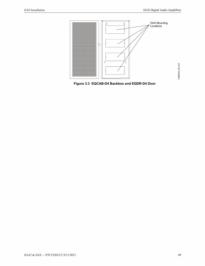
DAA2 & DAX — P/N 53265:C2 9/11/2013 49
DAX Installation DAX Digital Audio Amplifiers
Figure 3.3 EQCAB-D4 Backbox and EQDR-D4 Door
DAX Mounting Locations
CA
BD
AA
_D
4.w
mf
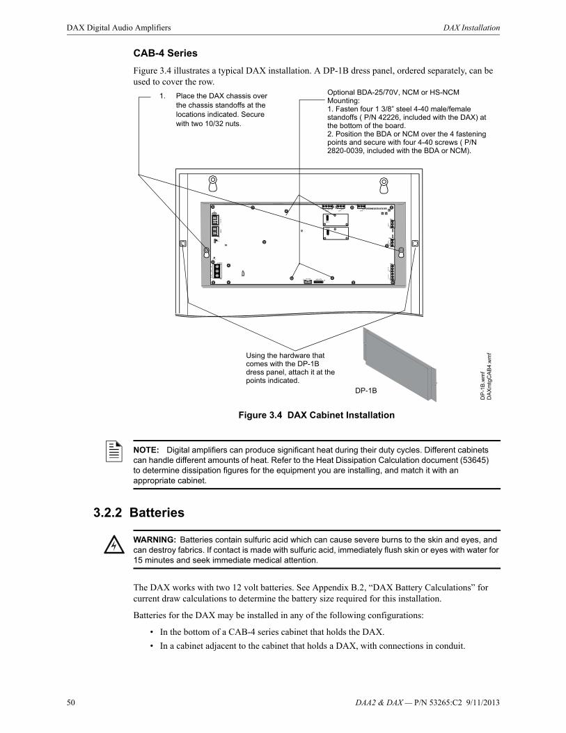
50 DAA2 & DAX — P/N 53265:C2 9/11/2013
DAX Digital Audio Amplifiers DAX Installation
CAB-4 Series
Figure 3.4 illustrates a typical DAX installation. A DP-1B dress panel, ordered separately, can be used to cover the row.
Figure 3.4 DAX Cabinet Installation
3.2.2 Batteries
The DAX works with two 12 volt batteries. See Appendix B.2, “DAX Battery Calculations” for current draw calculations to determine the battery size required for this installation.
Batteries for the DAX may be installed in any of the following configurations:
• In the bottom of a CAB-4 series cabinet that holds the DAX.
• In a cabinet adjacent to the cabinet that holds a DAX, with connections in conduit.
1. Place the DAX chassis over the chassis standoffs at the locations indicated. Secure with two 10/32 nuts.
DA
Xm
tgC
AB
4.w
mfUsing the hardware that
comes with the DP-1B dress panel, attach it at the points indicated.
DP-1B
DP
-1B
.wm
f
Optional BDA-25/70V, NCM or HS-NCM Mounting:1. Fasten four 1 3/8” steel 4-40 male/female standoffs ( P/N 42226, included with the DAX) at the bottom of the board.2. Position the BDA or NCM over the 4 fastening points and secure with four 4-40 screws ( P/N 2820-0039, included with the BDA or NCM).
NOTE: Digital amplifiers can produce significant heat during their duty cycles. Different cabinets can handle different amounts of heat. Refer to the Heat Dissipation Calculation document (53645) to determine dissipation figures for the equipment you are installing, and match it with an appropriate cabinet.
!WARNING: Batteries contain sulfuric acid which can cause severe burns to the skin and eyes, and can destroy fabrics. If contact is made with sulfuric acid, immediately flush skin or eyes with water for 15 minutes and seek immediate medical attention.
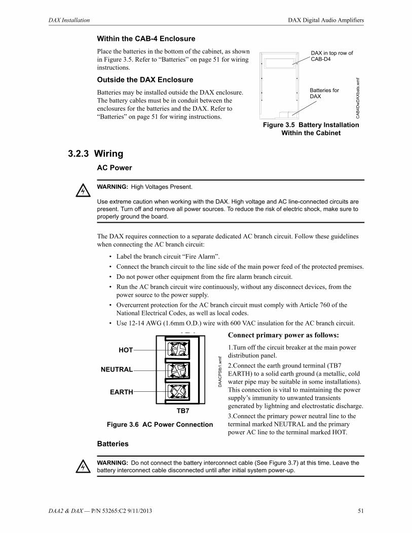
DAA2 & DAX — P/N 53265:C2 9/11/2013 51
DAX Installation DAX Digital Audio Amplifiers
Within the CAB-4 Enclosure
Place the batteries in the bottom of the cabinet, as shown in Figure 3.5. Refer to “Batteries” on page 51 for wiring instructions.
Outside the DAX Enclosure
Batteries may be installed outside the DAX enclosure. The battery cables must be in conduit between the enclosures for the batteries and the DAX. Refer to “Batteries” on page 51 for wiring instructions.
3.2.3 Wiring
AC Power
The DAX requires connection to a separate dedicated AC branch circuit. Follow these guidelines when connecting the AC branch circuit:
• Label the branch circuit “Fire Alarm”.
• Connect the branch circuit to the line side of the main power feed of the protected premises.
• Do not power other equipment from the fire alarm branch circuit.
• Run the AC branch circuit wire continuously, without any disconnect devices, from the power source to the power supply.
• Overcurrent protection for the AC branch circuit must comply with Article 760 of the National Electrical Codes, as well as local codes.
• Use 12-14 AWG (1.6mm O.D.) wire with 600 VAC insulation for the AC branch circuit.
Connect primary power as follows:
1.Turn off the circuit breaker at the main power distribution panel.
2.Connect the earth ground terminal (TB7 EARTH) to a solid earth ground (a metallic, cold water pipe may be suitable in some installations). This connection is vital to maintaining the power supply’s immunity to unwanted transients generated by lightning and electrostatic discharge.
3.Connect the primary power neutral line to the terminal marked NEUTRAL and the primary power AC line to the terminal marked HOT.
Batteries
CA
B4
Dw
DA
Xb
ats.
wm
f
DAX in top row of CAB-D4
Figure 3.5 Battery Installation Within the Cabinet
Batteries for DAX
!WARNING: High Voltages Present.
Use extreme caution when working with the DAX. High voltage and AC line-connected circuits are present. Turn off and remove all power sources. To reduce the risk of electric shock, make sure to properly ground the board.
Figure 3.6 AC Power Connection
EARTH
NEUTRAL
HOT
DA
AC
PS
tb1
.wm
f
TB7
!WARNING: Do not connect the battery interconnect cable (See Figure 3.7) at this time. Leave the battery interconnect cable disconnected until after initial system power-up.

52 DAA2 & DAX — P/N 53265:C2 9/11/2013
DAX Digital Audio Amplifiers DAX Installation
The DAX works with two 12 volt batteries. See Appendix B.2, “DAX Battery Calculations” for current draw calculations to determine the battery size required for this installation.
Battery cables (90”, 2.28 m) are included with the DAX for battery installation in any CAB-4 series cabinet that includes a DAX in one of the rows. Shorter battery cables (18”, 0.5 m) are included with the CHS-BH1. For battery sharing, use 12 AWG wire either in the same cabinet, or in conduit for no more than 20 ft. (6.09 m..
Batteries Within the Same Enclosure
Refer to Figure 3.7 for battery connections.
Figure 3.7 Connecting Batteries to TB8 and TB9
Batteries Outside the DAX Enclosure
When the batteries are installed outside the DAX cabinet, connections are the same as in Figure 3.7. However, the battery cables between the two enclosures must be in conduit and the enclosures must be within 20 feet (6.09 m) of each other within the same room.
Figure 3.8 Using Conduit
Battery Sharing
DAX-35:
Up to four DAX-35s may share a set of batteries.
• The ground fault switch on the DAX (SW5) must be set to “Disable” on all but one 35 watt DAX attached to the set of batteries.
• In VeriFire Tools programming, “Disable Charger” must be checked in the “DAX Amplifier Programming Service - General II” screen for all but one 35 watt DAX.
The enabled ground fault switch does not have to be on the same DAX as the enabled charger.
DA
XP
Sto
batts
.wm
f
Battery Interconnect Cable, P/N
71070Leave disconnected
until after initial system power-up.
P/N 75560 (pos)
P/N 75561 (neg)
NOTE: DAX-50 only. Batteries must also be connected to a battery-charging device that is monitored by a fire panel.
DA
Xb
atte
xte
rna
l.wm
fDAXBatteries
Conduit between enclosures
Battery Interconnect
CableLeave disconnected until after initial system power-up.
NOTE: DAX-50 only. Batteries must also be connected to a battery-charging device that is monitored by a fire panel.
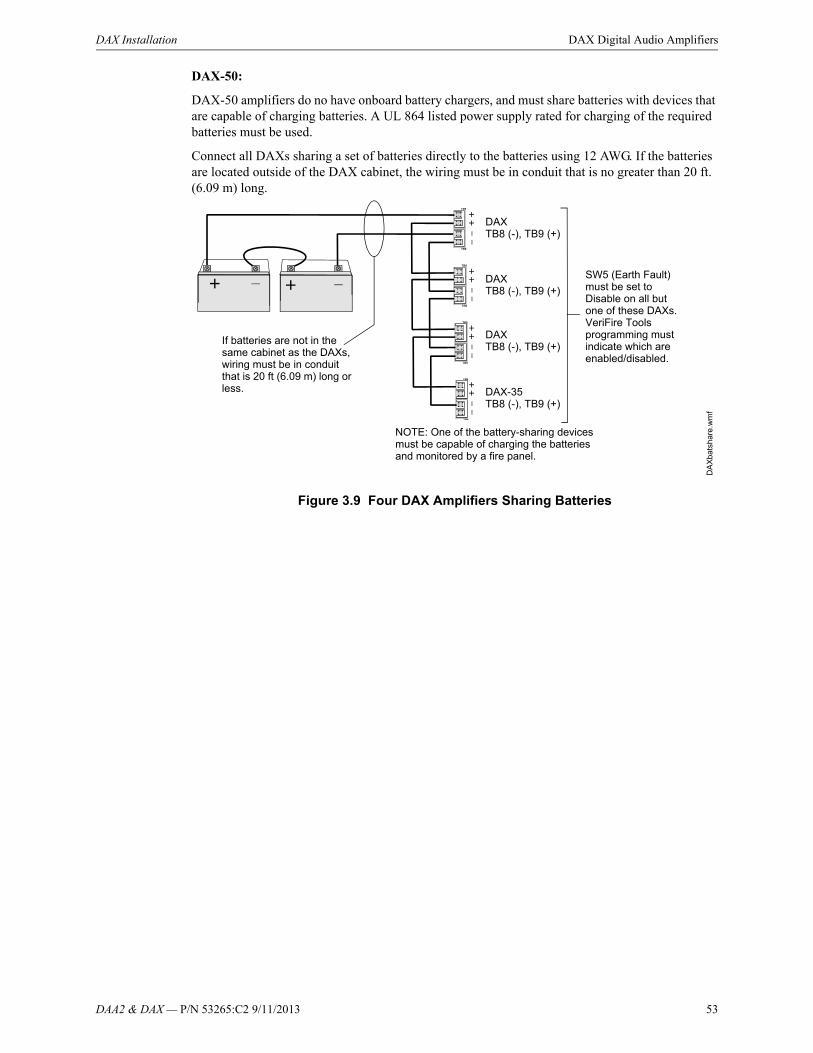
DAA2 & DAX — P/N 53265:C2 9/11/2013 53
DAX Installation DAX Digital Audio Amplifiers
DAX-50:
DAX-50 amplifiers do no have onboard battery chargers, and must share batteries with devices that are capable of charging batteries. A UL 864 listed power supply rated for charging of the required batteries must be used.
Connect all DAXs sharing a set of batteries directly to the batteries using 12 AWG. If the batteries are located outside of the DAX cabinet, the wiring must be in conduit that is no greater than 20 ft. (6.09 m) long.
Figure 3.9 Four DAX Amplifiers Sharing Batteries
DA
Xb
atsh
are.
wm
f
DAXTB8 (-), TB9 (+)
If batteries are not in the same cabinet as the DAXs, wiring must be in conduit that is 20 ft (6.09 m) long or less.
SW5 (Earth Fault) must be set to Disable on all but one of these DAXs. VeriFire Tools programming must indicate which are enabled/disabled.
DAXTB8 (-), TB9 (+)
DAXTB8 (-), TB9 (+)
DAX-35TB8 (-), TB9 (+)
NOTE: One of the battery-sharing devices must be capable of charging the batteries and monitored by a fire panel.

54 DAA2 & DAX — P/N 53265:C2 9/11/2013
DAX Digital Audio Amplifiers DAX Installation
Alarm Bus
The DAX general alarm connections are used to receive general alarm messages from an FACP via an SLC device, or via the Notification Appliance Circuit of an FACP or power supply.
The Alarm Bus can be used for local activations when the DAA2 has lost communications with the DVC. The Alarm Bus can also be used as a point in logic equations in the local DVC or network DVCs.
Figure 3.10 Alarm Bus Connections to FCM-1
Figure 3.11 Alarm Bus Connections to NAC
Refer to the SLC manual and specific panel or power supply manual for more information.
FCM-1*
ALARM Bus to next DAX ELR-47K, 1/2 watt resistor
DAX FZ
MF
CM
pH
a.w
mf
DA
XT
B3
.wm
f
14-18 AWG twisted-pair recommended
Program the control module at the FACP with an appropriate alarm Type ID per the FACP manual.
Alarm Bus requires minimum 16VDC at 20mA
across the terminals to activate. Nominal 24VDC.
DAX
To Power Supply
+- SLC
from FACP
SLC to next device
+-
+ -
+
- *If the SLC device does not match the one in this figure, refer to the SLC man-ual appendix, which contains wiring con-version charts for type V and type H mod-
NAC CircuitA -
A +
B +
B -
ALARM Bus to next DAX
DA
XT
B3
.wm
fELR per panel or power supply manual.
14-18 AWG twisted-pair recommended
Listed compatible panel or power supply with onboard NAC circuits.
Alarm Bus requires minimum of 16VDC at 20mA across the terminals to activate. Nominal 24VDC
DAX DAX
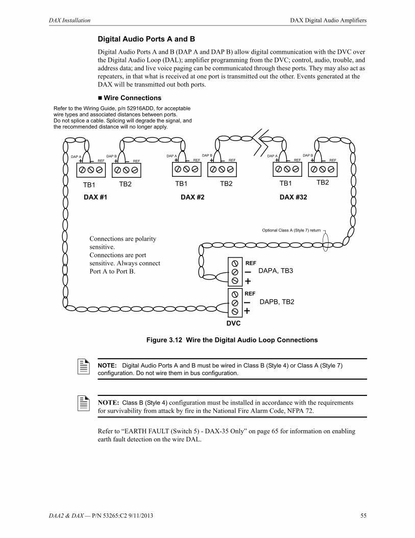
DAA2 & DAX — P/N 53265:C2 9/11/2013 55
DAX Installation DAX Digital Audio Amplifiers
Digital Audio Ports A and B
Digital Audio Ports A and B (DAP A and DAP B) allow digital communication with the DVC over the Digital Audio Loop (DAL); amplifier programming from the DVC; control, audio, trouble, and address data; and live voice paging can be communicated through these ports. They may also act as repeaters, in that what is received at one port is transmitted out the other. Events generated at the DAX will be transmitted out both ports.
Wire Connections
Figure 3.12 Wire the Digital Audio Loop Connections
Refer to “EARTH FAULT (Switch 5) - DAX-35 Only” on page 65 for information on enabling earth fault detection on the wire DAL.
TB1 TB2
DAP AREF
DAP B
REF
DAX #1
Refer to the Wiring Guide, p/n 52916ADD, for acceptable wire types and associated distances between ports.Do not splice a cable. Splicing will degrade the signal, and the recommended distance will no longer apply.
DAX #2 DAX #32
TB1 TB1TB2 TB2
DVC
DAPA, TB3
DAPB, TB2REF
Optional Class A (Style 7) return
Connections are polarity sensitive.Connections are port sensitive. Always connect Port A to Port B.
REF
DAP AREF
DAP B
REFDAP A
REFDAP B
REF
NOTE: Digital Audio Ports A and B must be wired in Class B (Style 4) or Class A (Style 7) configuration. Do not wire them in bus configuration.
NOTE: Class B (Style 4) configuration must be installed in accordance with the requirements for survivability from attack by fire in the National Fire Alarm Code, NFPA 72.
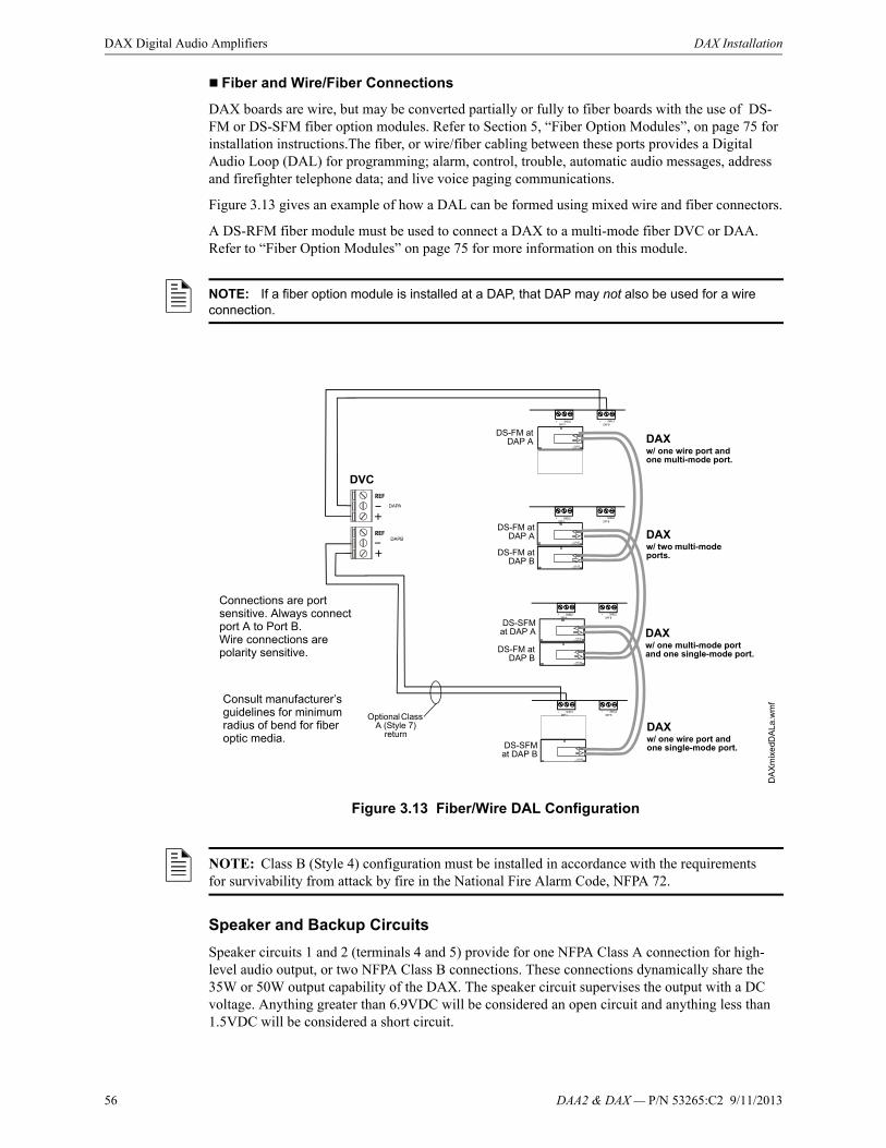
56 DAA2 & DAX — P/N 53265:C2 9/11/2013
DAX Digital Audio Amplifiers DAX Installation
Fiber and Wire/Fiber Connections
DAX boards are wire, but may be converted partially or fully to fiber boards with the use of DS-FM or DS-SFM fiber option modules. Refer to Section 5, “Fiber Option Modules”, on page 75 for installation instructions.The fiber, or wire/fiber cabling between these ports provides a Digital Audio Loop (DAL) for programming; alarm, control, trouble, automatic audio messages, address and firefighter telephone data; and live voice paging communications.
Figure 3.13 gives an example of how a DAL can be formed using mixed wire and fiber connectors.
A DS-RFM fiber module must be used to connect a DAX to a multi-mode fiber DVC or DAA. Refer to “Fiber Option Modules” on page 75 for more information on this module.
Figure 3.13 Fiber/Wire DAL Configuration
Speaker and Backup Circuits
Speaker circuits 1 and 2 (terminals 4 and 5) provide for one NFPA Class A connection for high-level audio output, or two NFPA Class B connections. These connections dynamically share the 35W or 50W output capability of the DAX. The speaker circuit supervises the output with a DC voltage. Anything greater than 6.9VDC will be considered an open circuit and anything less than 1.5VDC will be considered a short circuit.
NOTE: If a fiber option module is installed at a DAP, that DAP may not also be used for a wire connection.
DAXw/ one wire port and one multi-mode port.
DS-FM atDAP A DAX
w/ two multi-mode ports.
DAXw/ one multi-mode port and one single-mode port.
DS-FM atDAP B
DS-FM atDAP A
DS-FM atDAP B
DS-SFMat DAP A
DS-SFMat DAP B
DAXw/ one wire port and one single-mode port.
Optional Class A (Style 7)
return
DVC
Connections are port sensitive. Always connect port A to Port B.Wire connections are polarity sensitive.
Consult manufacturer’s guidelines for minimum radius of bend for fiber optic media.
DA
Xm
ixe
dDA
La.
wm
f
NOTE: Class B (Style 4) configuration must be installed in accordance with the requirements for survivability from attack by fire in the National Fire Alarm Code, NFPA 72.

DAA2 & DAX — P/N 53265:C2 9/11/2013 57
DAX Installation DAX Digital Audio Amplifiers
A DAX may be wired using TB10 and TB11, “BACKUP IN” and “BACKUP THRU” to back up an amplifier. If a DAX fails, the signal automatically switches to the backup DAX.
Each backup terminal block contains two sets of terminals. One set may be used for “backup in” applications, the other set for “backup through” applications.
Speaker and backup connections are illustrated in Figure 3.14.
In Normal (NAC) Mode
When a DAX’s Speaker Riser Mode is programmed NORMAL (refer to the DVC Digital Voice Command manual for programming description), the amplified signal from the DAX may be connected directly to speakers. Following are illustrations of Class A and Class B configurations (Figure 3.15).
Figure 3.15 Speaker Riser Mode: Normal
High-level audio Out, Ckt 1
12-18 AWG twisted-pair recommended
Figure 3.14 Speaker Circuit and Backup Connections
SHIELD
SHIELD
SHIELD
High-level audio Out, Ckt 2SHIELD
SHIELD
TB4
Backup In or Thru, Ckt 1
Backup In or Thru, Ckt 2
SHIELD
TB
10Backup In or Thru, Ckt 1
Backup In or Thru, Ckt 2
TB5
TB11
DAX
NOTE: The shield is connected at one end only.
High-Level Return
High-Level Out
R-10k
One DAX Class A Circuit
Two DAX Class B Circuits
20k ohm end-of-line resistor, p/n ELR-20k
20k ohm end-of-line resistor, p/n ELR-20k

58 DAA2 & DAX — P/N 53265:C2 9/11/2013
DAX Digital Audio Amplifiers DAX Installation
In Riser Mode to Additional Amplifiers
When a DAX’s Speaker Riser Mode is programmed RISER TO ADDITIONAL AMPLIFIERS (refer to the DVC Digital Voice Command manual for programming), the amplified signal from the DAX may be connected to an ACT-25 or ACT-70 Audio Coupling Transformer to drive additional AA-Series amplifiers. This mode provides a 200 Hz supervisory tone required by analog amplifiers.
Figure 3.16 DAX Riser Mode to Additional Amplifiers
Refer to the the ACT-25 and ACT-70 installation documents for more information.
In Riser Mode to Control Modules
When a DAX’s Speaker Riser Mode is programmed RISER TO CONTROL MODULES (refer to the DVC Digital Voice Command manual for programming), the amplified signal from the DAX may be routed to multiple speaker circuits using SLC control modules.
The control module must disable the power supply monitoring to prevent acting as a load on the supervision voltage. For V-type control modules, this requires a resistor cut under the label. For H-type modules, a jumper must be removed under the label. For XP6-C modules, a jumper must be removed for each address.
To prevent unnecessarily charging and discharging the supervision voltage of a control module and the supervision voltage of the DAA2, connect the amplifier (+) to the power supply (-) on the control module. Connect the amplifier (-) to the control module power supply (+) input.
Do not use background music in this mode. The DAX will provide speaker circuit supervision only when idle.
AA-100/AA-100Eor
AA-120/AA-120EAA-30/AA-30E
DA
X
Low-level Audio Low-level Audio
High-level AudioHigh-level AudioTo other audio coupling transformers or 20k ELR (Class B)
Optional 4-wire return from last ACT-HI
TB1
P1 P1
TB1
10k ELR (Class A)
DA
X_
AC
T_r
iser
mod
e.w
mf
Audio Coupling Transformer
AudioCoupling
Transformer
Up to 7 low-level
inputs
Up to 7 low-level
inputs
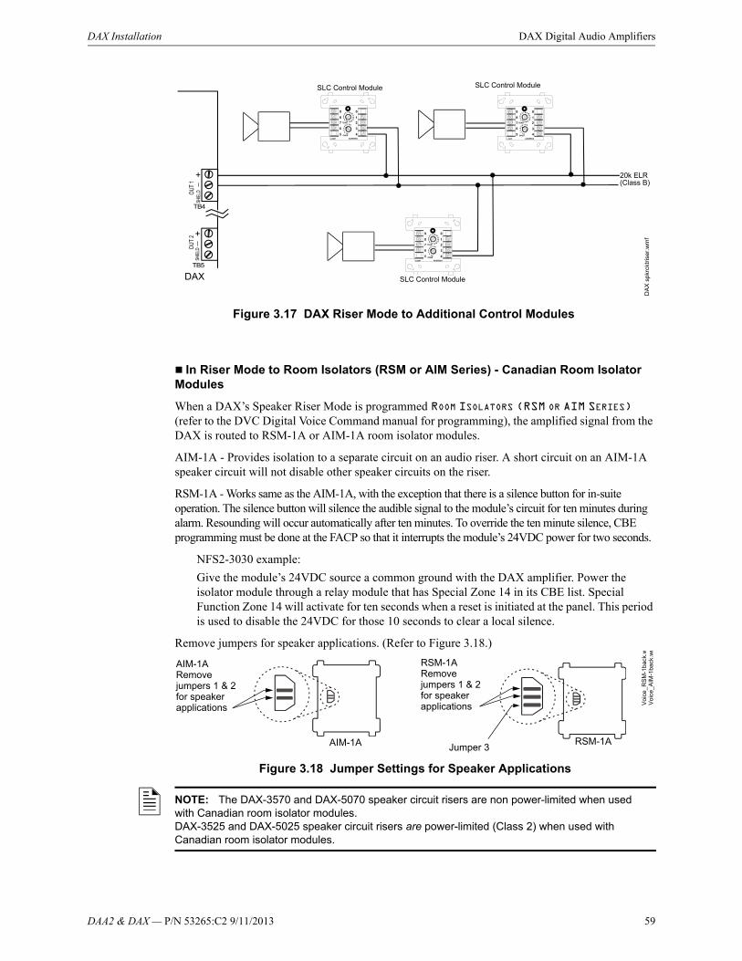
DAA2 & DAX — P/N 53265:C2 9/11/2013 59
DAX Installation DAX Digital Audio Amplifiers
In Riser Mode to Room Isolators (RSM or AIM Series) - Canadian Room Isolator Modules
When a DAX’s Speaker Riser Mode is programmed ROOM ISOLATORS (RSM OR AIM SERIES) (refer to the DVC Digital Voice Command manual for programming), the amplified signal from the DAX is routed to RSM-1A or AIM-1A room isolator modules.
AIM-1A - Provides isolation to a separate circuit on an audio riser. A short circuit on an AIM-1A speaker circuit will not disable other speaker circuits on the riser.
RSM-1A - Works same as the AIM-1A, with the exception that there is a silence button for in-suite operation. The silence button will silence the audible signal to the module’s circuit for ten minutes during alarm. Resounding will occur automatically after ten minutes. To override the ten minute silence, CBE programming must be done at the FACP so that it interrupts the module’s 24VDC power for two seconds.
NFS2-3030 example:
Give the module’s 24VDC source a common ground with the DAX amplifier. Power the isolator module through a relay module that has Special Zone 14 in its CBE list. Special Function Zone 14 will activate for ten seconds when a reset is initiated at the panel. This period is used to disable the 24VDC for those 10 seconds to clear a local silence.
Remove jumpers for speaker applications. (Refer to Figure 3.18.)
Figure 3.18 Jumper Settings for Speaker Applications
DAX
DA
X s
pkrc
ktri
ser.
wm
f
20k ELR (Class B)
SLC Control Module
SLC Control ModuleSLC Control Module
Figure 3.17 DAX Riser Mode to Additional Control Modules
AIM-1ARemove jumpers 1 & 2 for speaker applications
RSM-1ARemove jumpers 1 & 2 for speaker applications
Jumper 3
Vo
ice_
AIM
-1ba
ck.w
mV
oice
_RS
M-1
back
.w
AIM-1A RSM-1A
NOTE: The DAX-3570 and DAX-5070 speaker circuit risers are non power-limited when used with Canadian room isolator modules. DAX-3525 and DAX-5025 speaker circuit risers are power-limited (Class 2) when used with Canadian room isolator modules.

60 DAA2 & DAX — P/N 53265:C2 9/11/2013
DAX Digital Audio Amplifiers DAX Installation
In Riser Mode to Room Isolators (CIM or CSM Series) - Canadian Room Isolator Modules
When a DAX’s Speaker Riser Mode is programmed ROOM ISOLATORS (CIM OR CSM SERIES) (Refer to the DVC Digital Voice Command manual for programming), the amplified signal from the DAX is routed to a CIM-2A module, which feeds the signal to one or two CSM-1A modules.
A pre-announce tone of 800 Hz will clear a local silence.
Do not use background music in this mode. The DAX will provide speaker circuit supervision only when idle.
RSM-1A/AIM-1A
RSM-1A/AIM-1A
External 24V UL/ULC-listed power supply
DAX TB4DAX and power supply must share a common
ground.
DAX and power supply must share a common
ground.
External 24V UL/ULC-
listed power supply
Optional 4-wire return.
Supervised Speakers Unsupervised Speakers
Figure 3.19 DAX Riser Mode to RSM-1A/AIM-1A Modules
24V to next device
To next module, EOL resistor, orClass A return.
To next module, EOL resistor, or Class A return.
24V to next device
DAX TB4
DA
Xris
erm
od-R
SM
AIM
.wm
fD
AX
rise
rmo
d_R
SM
AIM
unsu
pv.w
mf
NOTE: The DAX-3570 and DAX-5070 speaker circuit risers are non power-limited when used with Canadian room isolator modules. DAX-3525 and DAX-5025 speaker circuit risers are power-limited (Class 2) when used with Canadian room isolator modules.

DAA2 & DAX — P/N 53265:C2 9/11/2013 61
DAX Installation DAX Digital Audio Amplifiers
Speaker Backup Circuits - TB10 and TB 11
The DAX supports one-to-one or one-to-many backup amplification. A BDA-25/70V backup amplifier may be used in a one-to-one backup application. Each DAX must be designated a primary or backup amplifier through VeriFire Tools programming. The speaker wiring from backup to primary is unsupervised when the backup amplifier is not active; therefore the backup and primary amplifiers must be in the same enclosure, or in conduit within the same room.
Each backup terminal block contains two sets of terminals. One set may be used for “backup in” applications, the other set for “backup through” applications.
Figure 3.20 DAX Riser Mode to Room Isolators (CIM or CSM Series)
CIM-2A
DAX TB 4
To next module, EOL resistor, orClass A return.
CSM-1A
CSM-1A
NOTE: In Style 4 wiring arrangements of the DAL (digital audio loop), it is recommended that the backup amplifier be located closer to the DVC than the primary DAX amplifiers on the DAL.
Each DAX acts as a repeater for the digital audio signal. If a primary amplifier falls off-line, the backup will not receive the signal if it is further down the DAL chain.
DVC
DVC
DAX Backup
DAX BackupDAX Primary
DAX PrimaryRecommended
Not Recommended
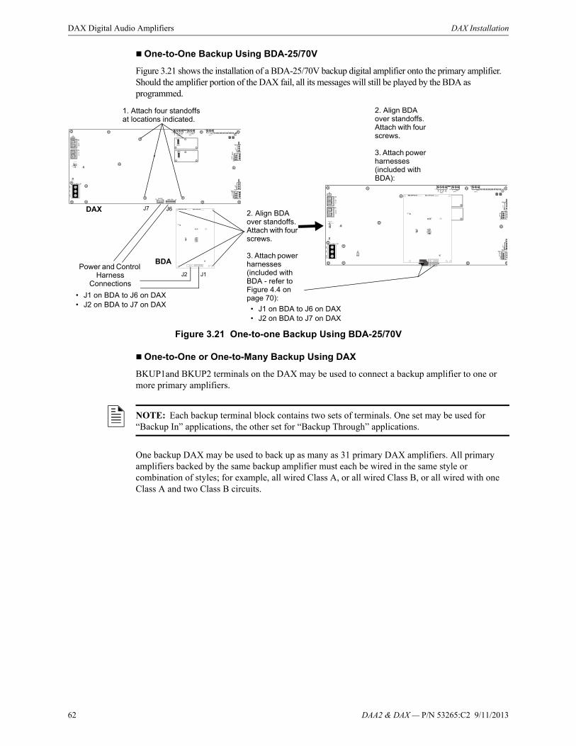
62 DAA2 & DAX — P/N 53265:C2 9/11/2013
DAX Digital Audio Amplifiers DAX Installation
One-to-One Backup Using BDA-25/70V
Figure 3.21 shows the installation of a BDA-25/70V backup digital amplifier onto the primary amplifier. Should the amplifier portion of the DAX fail, all its messages will still be played by the BDA as programmed.
Figure 3.21 One-to-one Backup Using BDA-25/70V
One-to-One or One-to-Many Backup Using DAX
BKUP1and BKUP2 terminals on the DAX may be used to connect a backup amplifier to one or more primary amplifiers.
One backup DAX may be used to back up as many as 31 primary DAX amplifiers. All primary amplifiers backed by the same backup amplifier must each be wired in the same style or combination of styles; for example, all wired Class A, or all wired Class B, or all wired with one Class A and two Class B circuits.
1. Attach four standoffs at locations indicated.
2. Align BDA over standoffs. Attach with four screws.
3. Attach power harnesses (included with BDA):
Power and Control Harness
Connections
BDA
DAX
• J1 on BDA to J6 on DAX• J2 on BDA to J7 on DAX
J2 J1
J7 J62. Align BDA over standoffs. Attach with four screws.
3. Attach power harnesses (included with BDA - refer to Figure 4.4 on page 70):
• J1 on BDA to J6 on DAX• J2 on BDA to J7 on DAX
NOTE: Each backup terminal block contains two sets of terminals. One set may be used for “Backup In” applications, the other set for “Backup Through” applications.

DAA2 & DAX — P/N 53265:C2 9/11/2013 63
DAX Installation DAX Digital Audio Amplifiers
A backup amplifier can support one failed primary amplifier at a time. Should another primary amplifier also fail, depending on load, the backup amplifier may also fail, generating an AMPLIFIER LIMIT trouble until the load is reduced or reset.
Figure 3.22 One-to-one or One-to-Many Backup Using BKUP Terminal Blocks
Wiring Fault Testing
Test wire-to-wire faults with 0 (zero) ohm impedance.
DAP A+
DAP A-
REF A
DVC
TB2
TB3
DAP B+
DAP B-
REF B
DAXPRIMARY
DAXBACKUP
Optional Class A Return
Digital Signal from DVC
DAPA DAPB+ +- SHLD - SHLD
TB4
TB10
TB5
TB11
+-S
HL
D
+-S
HL
D+-
SH
LD
+-S
HL
D
DAPA DAPB+ +- SHLD - SHLD
TB4
TB10
TB5
TB11
+-S
HL
D
+-S
HL
D
+-S
HL
D
+-S
HL
D
To next primary amplifier for one-to-many backup*
BKUP2TB 11
Speaker CircuitOUT2, TB5
To next primary amplifier for one-to-many backup*
BKUP1TB 10
Speaker CircuitOUT1, TB4
*Note: No end-of-line resistor is necessary at the last primary amplifier backup terminal.

64 DAA2 & DAX — P/N 53265:C2 9/11/2013
DAX Digital Audio Amplifiers DAX Installation
UL Power-limited (Class 2) Wiring Requirements
Power-limited and non-power-limited circuit wiring must remain separated in the cabinet. All power-limited circuit wiring must remain at least 0.25 inches (6.35 mm) from any non-power-limited circuit wiring. All power-limited and non-power-limited circuit wiring must enter and exit the cabinet through different knockouts and/or conduits.
Figure 3.23 Typical Backbox Wiring
Figure 3.24 Backbox Wiring with DAX-3570 or DAX-5070 and Canadian Room Isolator Modules
Power-limited (Class 2)circuits
Non-power-limited circuits
DA
XU
Lwiri
nga
.wm
f
Power-limited (Class 2) circuits
Non-power-limited circuits
DA
XU
Lw
irin
ga.
wm
fNon-power-
limited circuits
to Canadian room isolator
modules
to Canadian room isolator
modules
DAX-3570 or DAX-5070
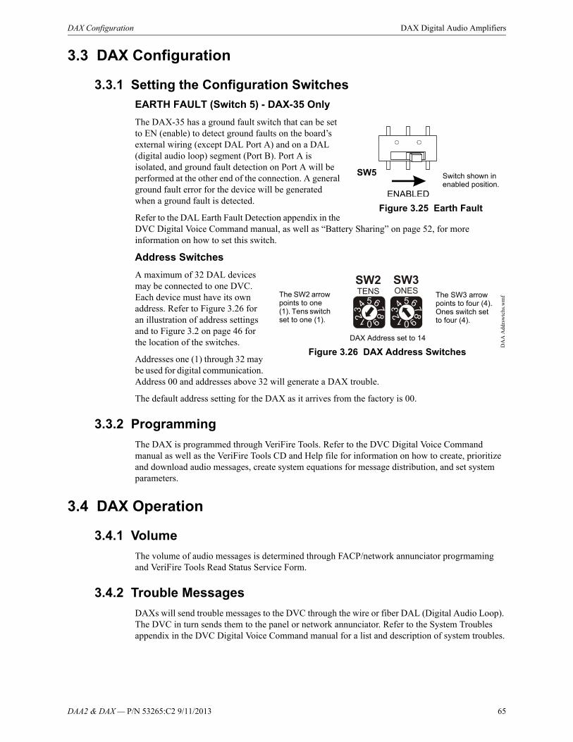
DAA2 & DAX — P/N 53265:C2 9/11/2013 65
DAX Configuration DAX Digital Audio Amplifiers
3.3 DAX Configuration
3.3.1 Setting the Configuration Switches
EARTH FAULT (Switch 5) - DAX-35 Only
The DAX-35 has a ground fault switch that can be set to EN (enable) to detect ground faults on the board’s external wiring (except DAL Port A) and on a DAL (digital audio loop) segment (Port B). Port A is isolated, and ground fault detection on Port A will be performed at the other end of the connection. A general ground fault error for the device will be generated when a ground fault is detected.
Refer to the DAL Earth Fault Detection appendix in the DVC Digital Voice Command manual, as well as “Battery Sharing” on page 52, for more information on how to set this switch.
Address Switches
A maximum of 32 DAL devices may be connected to one DVC. Each device must have its own address. Refer to Figure 3.26 for an illustration of address settings and to Figure 3.2 on page 46 for the location of the switches.
Addresses one (1) through 32 may be used for digital communication. Address 00 and addresses above 32 will generate a DAX trouble.
The default address setting for the DAX as it arrives from the factory is 00.
3.3.2 Programming
The DAX is programmed through VeriFire Tools. Refer to the DVC Digital Voice Command manual as well as the VeriFire Tools CD and Help file for information on how to create, prioritize and download audio messages, create system equations for message distribution, and set system parameters.
3.4 DAX Operation
3.4.1 Volume
The volume of audio messages is determined through FACP/network annunciator progrmaming and VeriFire Tools Read Status Service Form.
3.4.2 Trouble Messages
DAXs will send trouble messages to the DVC through the wire or fiber DAL (Digital Audio Loop). The DVC in turn sends them to the panel or network annunciator. Refer to the System Troubles appendix in the DVC Digital Voice Command manual for a list and description of system troubles.
Figure 3.25 Earth Fault
Switch shown in enabled position.
Figure 3.26 DAX Address Switches
DAX Address set to 14
The SW2 arrow points to one (1). Tens switch set to one (1).
The SW3 arrow points to four (4). Ones switch set to four (4).
DA
A A
ddrs
wtc
hs.w
mf
66 DAA2 & DAX — P/N 53265:C2 9/11/2013
DAX Digital Audio Amplifiers DAX Operation
3.4.3 Read/Alter Status
An NCA-2, NFS2-3030, NFS-3030, and network workstation, as well as a computer running VeriFire Tools, will be able to read the status of a DAX and its speaker circuits. Refer to the appropriate panel manual or the VeriFire Tools Read Status Service Form.
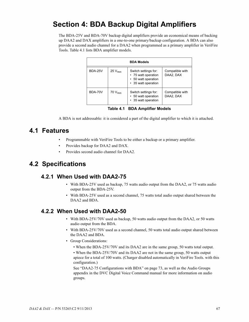
DAA2 & DAX — P/N 53265:C2 9/11/2013 67
Section 4: BDA Backup Digital AmplifiersThe BDA-25V and BDA-70V backup digital amplifiers provide an economical means of backing up DAA2 and DAX amplifiers in a one-to-one primary/backup configuration. A BDA can also provide a second audio channel for a DAA2 when programmed as a primary amplifier in VeriFire Tools. Table 4.1 lists BDA amplifier models.
A BDA is not addressable: it is considered a part of the digital amplifier to which it is attached.
4.1 Features• Programmable with VeriFire Tools to be either a backup or a primary amplifier.
• Provides backup for DAA2 and DAX.
• Provides second audio channel for DAA2.
4.2 Specifications
4.2.1 When Used with DAA2-75• With BDA-25V used as backup, 75 watts audio output from the DAA2, or 75 watts audio
output from the BDA-25V.
• With BDA-25V used as a second channel, 75 watts total audio output shared between the DAA2 and BDA.
4.2.2 When Used with DAA2-50• With BDA-25V/70V used as backup, 50 watts audio output from the DAA2, or 50 watts
audio output from the BDA.
• With BDA-25V/70V used as a second channel, 50 watts total audio output shared between the DAA2 and BDA.
• Group Considerations:
• When the BDA-25V/70V and its DAA2 are in the same group, 50 watts total output.
• When the BDA-25V/70V and its DAA2 are not in the same group, 50 watts output apiece for a total of 100 watts. (Charger disabled automatically in VeriFire Tools. with this configuration.)
See “DAA2-75 Configurations with BDA” on page 73, as well as the Audio Groups appendix in the DVC Digital Voice Command manual for more information on audio groups.
BDA Models
BDA-25V 25 VRMS Switch settings for:• 75 watt operation• 50 watt operation• 35 watt operation
Compatible with DAA2, DAX
BDA-70V 70 VRMS Switch settings for:• 50 watt operation• 35 watt operation
Compatible with DAA2, DAX
Table 4.1 BDA Amplifier Models
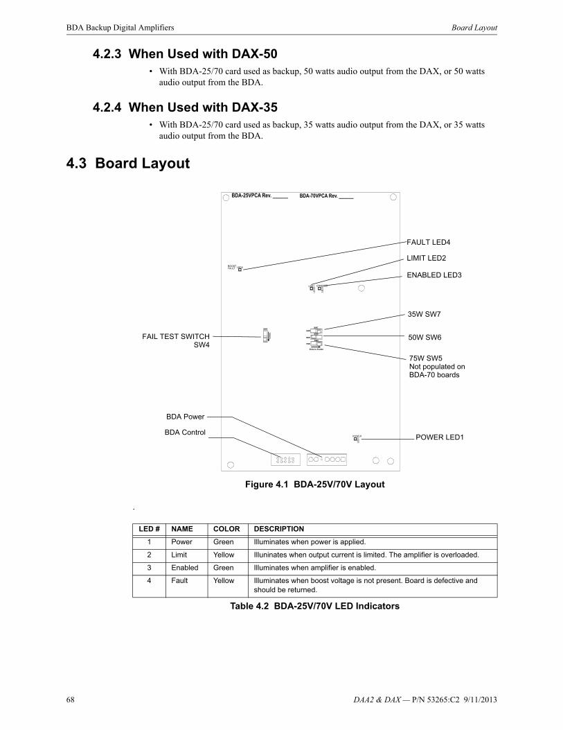
68 DAA2 & DAX — P/N 53265:C2 9/11/2013
BDA Backup Digital Amplifiers Board Layout
4.2.3 When Used with DAX-50• With BDA-25/70 card used as backup, 50 watts audio output from the DAX, or 50 watts
audio output from the BDA.
4.2.4 When Used with DAX-35• With BDA-25/70 card used as backup, 35 watts audio output from the DAX, or 35 watts
audio output from the BDA.
4.3 Board Layout
Figure 4.1 BDA-25V/70V Layout
.
LED # NAME COLOR DESCRIPTION
1 Power Green Illuminates when power is applied.
2 Limit Yellow Illuninates when output current is limited. The amplifier is overloaded.
3 Enabled Green Illuminates when amplifier is enabled.
4 Fault Yellow Illuminates when boost voltage is not present. Board is defective and should be returned.
Table 4.2 BDA-25V/70V LED Indicators
FAULT LED4
LIMIT LED2
ENABLED LED3
POWER LED1
FAIL TEST SWITCHSW4
35W SW7
50W SW6
75W SW5Not populated on BDA-70 boards
BDA Power
BDA Control

DAA2 & DAX — P/N 53265:C2 9/11/2013 69
Installation BDA Backup Digital Amplifiers
The switches described in Table 4.3 are for configuring the BDA-25/70.
Table 4.3 BDA-25V/70V Switches
4.4 Installation
4.4.1 DAA2
Figure 4.2 shows the installation of a BDA-25/70V onto a DAA2 amplifier. The BDA may be programmed and wired for backup or for providing a second audio channel.
Figure 4.2 BDA-25V/70V Installation, DAA2
Name Switch # Description Default
FAIL TEST SWITCH
SW4 Simulates an amplifier failure for testing backup amplfiers. Refer to page 71.
Normal
75W SW5 Sets the board for 75 watt operation. Not populated for BDA-70’s. Disabled
50W SW6 Sets the board for 50 watt operation. Disabled
35W SW7 Sets the board for 35 watt operation. Disabled
1. Attach four standoffs (p/n 42227) at locations indicated.
2. Align BDA over standoffs. Attach with four screws.
3. Attach power harnesses (included with BDA - refer to Figure 4.4 on page 70):
Power and Control Harness
Connections
BDA
DAA2
• J1 on BDA to J6 on DAA2• J2 on BDA to J5 on DAA2
J2 J1
J5 J6

70 DAA2 & DAX — P/N 53265:C2 9/11/2013
BDA Backup Digital Amplifiers Installation
4.4.2 DAX
Figure 4.3 shows the installation of a BDA-25/70V onto a DAX amplifier. The BDA may be programmed and wired for backup.
Figure 4.3 BDA-25V/70V Installation, DAX
4.4.3 BDA Power and Control Cables
Figure 4.4 BDA Control and Power Cables
1. Attach four standoffs at locations indicated.
2. Align BDA over standoffs. Attach with four screws.
3. Attach power harnesses (included with BDA - refer to Figure 4.4):
Power and Control Harness
Connections
BDADAX
J2 J1
J7 J6
• J1 on BDA to J6 on DAX• J2 on BDA to J7 on DAX
BDA Control cable, p/n 75690
Align tab with notch in board connector.
Tab
BDA Power cable, p/n 75689
Align cable connectors over spaces and pins.
Align where there is no pin.
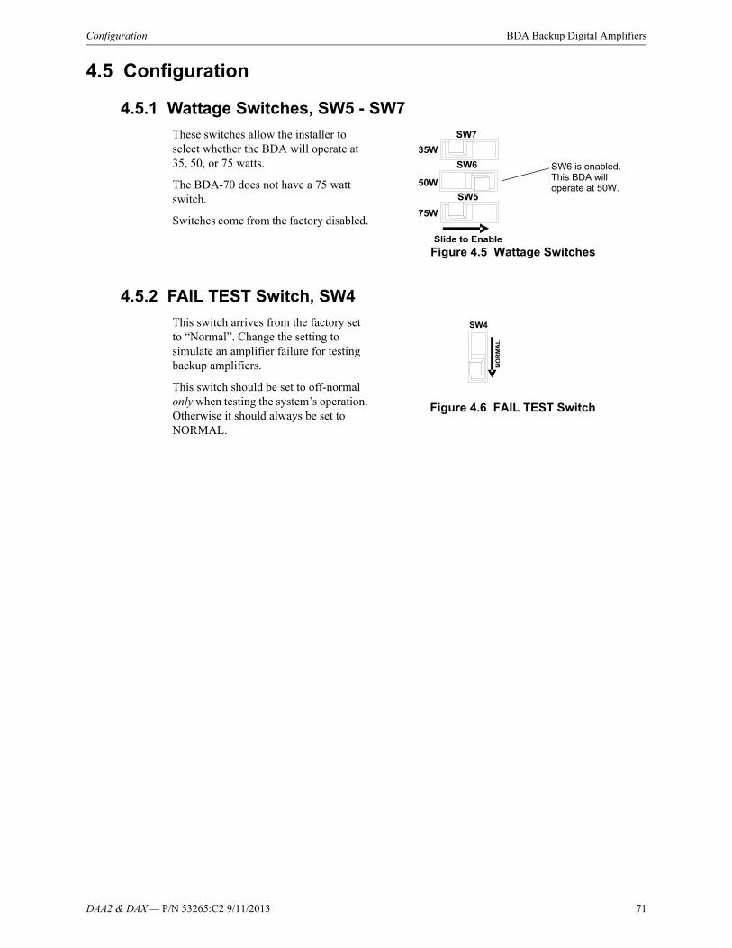
DAA2 & DAX — P/N 53265:C2 9/11/2013 71
Configuration BDA Backup Digital Amplifiers
4.5 Configuration
4.5.1 Wattage Switches, SW5 - SW7
These switches allow the installer to select whether the BDA will operate at 35, 50, or 75 watts.
The BDA-70 does not have a 75 watt switch.
Switches come from the factory disabled.
4.5.2 FAIL TEST Switch, SW4
This switch arrives from the factory set to “Normal”. Change the setting to simulate an amplifier failure for testing backup amplifiers.
This switch should be set to off-normal only when testing the system’s operation. Otherwise it should always be set to NORMAL.
Figure 4.5 Wattage Switches
SW6 is enabled. This BDA will operate at 50W.
Figure 4.6 FAIL TEST Switch
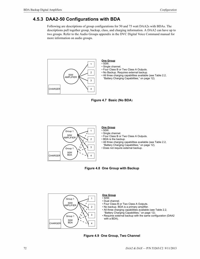
72 DAA2 & DAX — P/N 53265:C2 9/11/2013
BDA Backup Digital Amplifiers Configuration
4.5.3 DAA2-50 Configurations with BDA
Following are descriptions of group configurations for 50 and 75 watt DAA2s with BDAs. The descriptions pull together group, backup, class, and charging information. A DAA2 can have up to two groups. Refer to the Audio Groups appendix in the DVC Digital Voice Command manual for more information on audio groups.
Figure 4.7 Basic (No BDA)
Figure 4.8 One Group with Backup
Figure 4.9 One Group, Two Channel
CHARGER
50WAMPLIFIER
1
2
3
4
One Group• 50W.• Single channel.• Four Class B or Two Class A Outputs.• No Backup. Requires external backup.• All three charging capabilities available (see Table 2.2,
“Battery Charging Capabilities,” on page 12).
CHARGER
50WAMPLIFIER
1
2
3
4
One Group• 50W.• Single channel.• Four Class B or Two Class A Outputs.• BDA is the backup.• All three charging capabilities available (see Table 2.2,
“Battery Charging Capabilities,” on page 12).• Does not require external backup.
Group 1
50WBDA
Group 1
CHARGER
50WAMPLIFIER
1
2
3
4
One Group• 50W.• Dual channel.• Four Class B or Two Class A Outputs.• No backup. BDA is a primary amplifier.• All three charging capabilities available (see Table 2.2,
“Battery Charging Capabilities,” on page 12).• Requires external backup with the same configuration (DAA2
with a BDA).
Group 1
50WBDA
Group 1
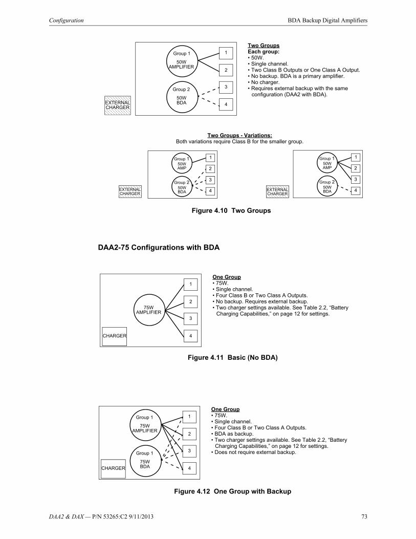
DAA2 & DAX — P/N 53265:C2 9/11/2013 73
Configuration BDA Backup Digital Amplifiers
DAA2-75 Configurations with BDA
Figure 4.11 Basic (No BDA)
Figure 4.12 One Group with Backup
50WAMPLIFIER
1
2
3
4
Two GroupsEach group:• 50W.• Single channel.• Two Class B Outputs or One Class A Output.• No backup. BDA is a primary amplifier.• No charger.• Requires external backup with the same
configuration (DAA2 with BDA).
Group 1
50WBDA
Group 2
Two Groups - Variations:Both variations require Class B for the smaller group.
EXTERNALCHARGER
50WAMP
Group 1
50WBDA
Group 2
1
3
4
250WAMP
Group 1
50WBDA
Group 2
1
3
4
2
EXTERNALCHARGER
EXTERNALCHARGER
Figure 4.10 Two Groups
CHARGER
75WAMPLIFIER
1
2
3
4
One Group• 75W.• Single channel.• Four Class B or Two Class A Outputs.• No backup. Requires external backup.• Two charger settings available. See Table 2.2, “Battery
Charging Capabilities,” on page 12 for settings.
CHARGER
75WAMPLIFIER
1
2
3
4
One Group• 75W.• Single channel.• Four Class B or Two Class A Outputs.• BDA as backup.• Two charger settings available. See Table 2.2, “Battery
Charging Capabilities,” on page 12 for settings.• Does not require external backup.
Group 1
75WBDA
Group 1

74 DAA2 & DAX — P/N 53265:C2 9/11/2013
BDA Backup Digital Amplifiers Configuration
Figure 4.13 One group, Two Channel
4.5.4 Operation
Volume
The volume of the BDA’s group can be changed using VeriFire Tools, NCA-2, ONYXWORKS, or direct-connect NFS2-3030.
75WAMPLIFIER
1
2
3
4
One Group• 75W.• Dual channel.• Four Class B or Two Class A Outputs.• No backup. BDA is extra channel.• Requires external backup.• Two charger settings available. See Table 2.2, “Battery
Charging Capabilities,” on page 12 for settings.
Group 1
75WBDA
Group 1
CHARGER
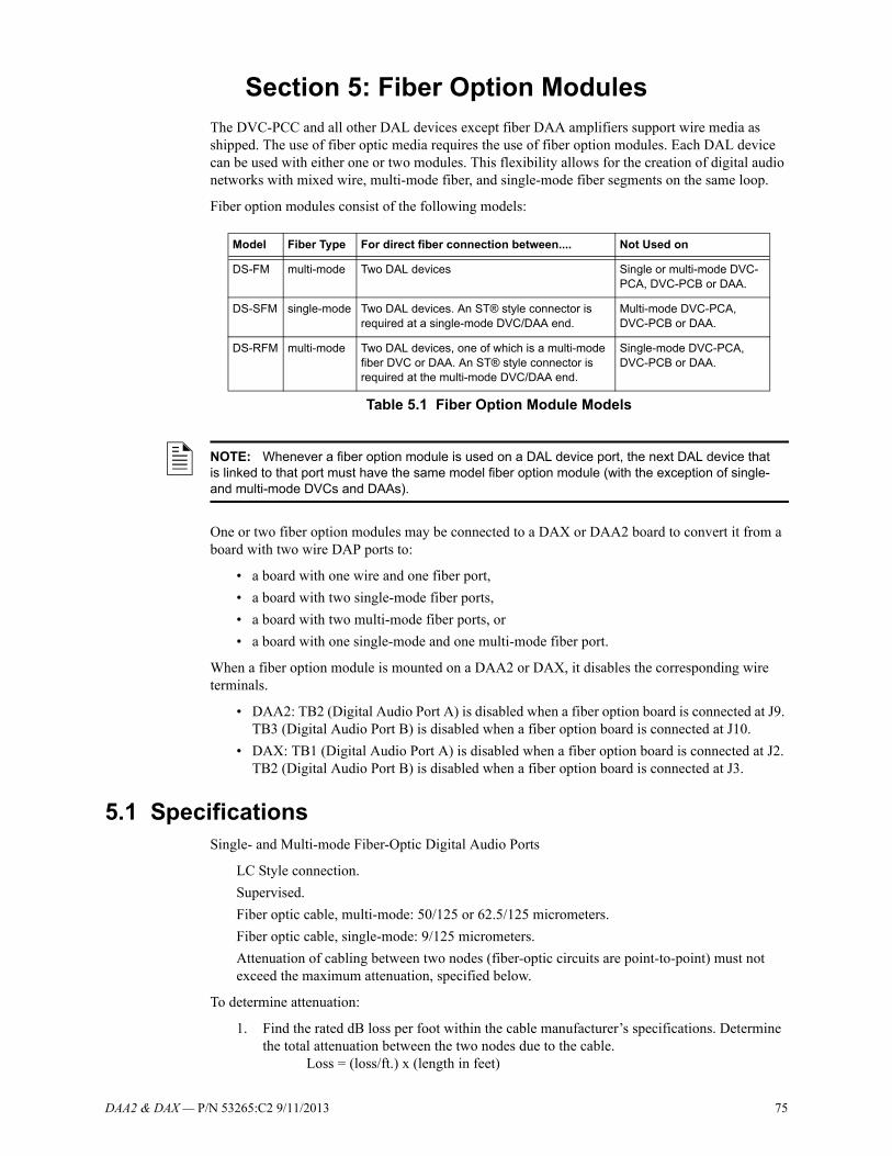
DAA2 & DAX — P/N 53265:C2 9/11/2013 75
Section 5: Fiber Option ModulesThe DVC-PCC and all other DAL devices except fiber DAA amplifiers support wire media as shipped. The use of fiber optic media requires the use of fiber option modules. Each DAL device can be used with either one or two modules. This flexibility allows for the creation of digital audio networks with mixed wire, multi-mode fiber, and single-mode fiber segments on the same loop.
Fiber option modules consist of the following models:
One or two fiber option modules may be connected to a DAX or DAA2 board to convert it from a board with two wire DAP ports to:
• a board with one wire and one fiber port,
• a board with two single-mode fiber ports,
• a board with two multi-mode fiber ports, or
• a board with one single-mode and one multi-mode fiber port.
When a fiber option module is mounted on a DAA2 or DAX, it disables the corresponding wire terminals.
• DAA2: TB2 (Digital Audio Port A) is disabled when a fiber option board is connected at J9. TB3 (Digital Audio Port B) is disabled when a fiber option board is connected at J10.
• DAX: TB1 (Digital Audio Port A) is disabled when a fiber option board is connected at J2. TB2 (Digital Audio Port B) is disabled when a fiber option board is connected at J3.
5.1 SpecificationsSingle- and Multi-mode Fiber-Optic Digital Audio Ports
LC Style connection.
Supervised.
Fiber optic cable, multi-mode: 50/125 or 62.5/125 micrometers.
Fiber optic cable, single-mode: 9/125 micrometers.
Attenuation of cabling between two nodes (fiber-optic circuits are point-to-point) must not exceed the maximum attenuation, specified below.
To determine attenuation:
1. Find the rated dB loss per foot within the cable manufacturer’s specifications. Determine the total attenuation between the two nodes due to the cable. Loss = (loss/ft.) x (length in feet)
Model Fiber Type For direct fiber connection between.... Not Used on
DS-FM multi-mode Two DAL devices Single or multi-mode DVC-PCA, DVC-PCB or DAA.
DS-SFM single-mode Two DAL devices. An ST® style connector is required at a single-mode DVC/DAA end.
Multi-mode DVC-PCA, DVC-PCB or DAA.
DS-RFM multi-mode Two DAL devices, one of which is a multi-mode fiber DVC or DAA. An ST® style connector is required at the multi-mode DVC/DAA end.
Single-mode DVC-PCA, DVC-PCB or DAA.
Table 5.1 Fiber Option Module Models
NOTE: Whenever a fiber option module is used on a DAL device port, the next DAL device that is linked to that port must have the same model fiber option module (with the exception of single- and multi-mode DVCs and DAAs).
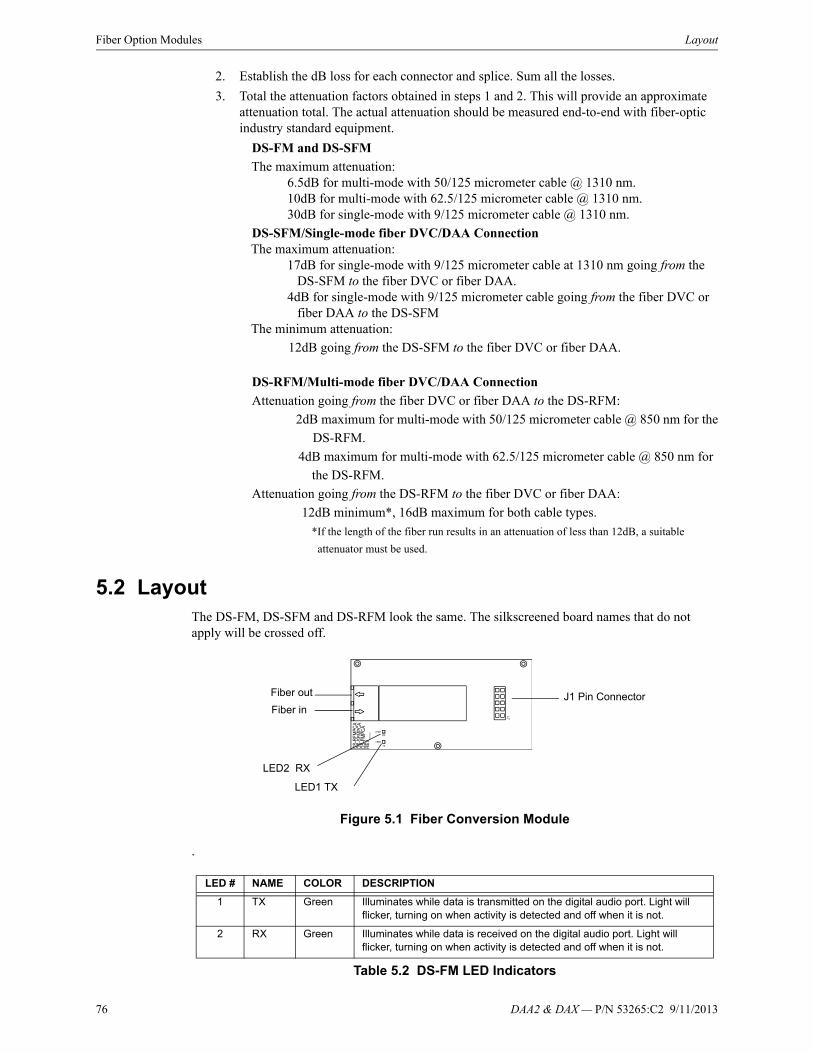
76 DAA2 & DAX — P/N 53265:C2 9/11/2013
Fiber Option Modules Layout
2. Establish the dB loss for each connector and splice. Sum all the losses.
3. Total the attenuation factors obtained in steps 1 and 2. This will provide an approximate attenuation total. The actual attenuation should be measured end-to-end with fiber-optic industry standard equipment.
DS-FM and DS-SFM
The maximum attenuation:6.5dB for multi-mode with 50/125 micrometer cable @ 1310 nm.10dB for multi-mode with 62.5/125 micrometer cable @ 1310 nm.30dB for single-mode with 9/125 micrometer cable @ 1310 nm.
DS-SFM/Single-mode fiber DVC/DAA ConnectionThe maximum attenuation:
17dB for single-mode with 9/125 micrometer cable at 1310 nm going from the DS-SFM to the fiber DVC or fiber DAA.4dB for single-mode with 9/125 micrometer cable going from the fiber DVC or fiber DAA to the DS-SFM
The minimum attenuation:
12dB going from the DS-SFM to the fiber DVC or fiber DAA.
DS-RFM/Multi-mode fiber DVC/DAA Connection
Attenuation going from the fiber DVC or fiber DAA to the DS-RFM:
2dB maximum for multi-mode with 50/125 micrometer cable @ 850 nm for the
DS-RFM.
4dB maximum for multi-mode with 62.5/125 micrometer cable @ 850 nm for
the DS-RFM.
Attenuation going from the DS-RFM to the fiber DVC or fiber DAA:
12dB minimum*, 16dB maximum for both cable types.
*If the length of the fiber run results in an attenuation of less than 12dB, a suitable
attenuator must be used.
5.2 LayoutThe DS-FM, DS-SFM and DS-RFM look the same. The silkscreened board names that do not apply will be crossed off.
Figure 5.1 Fiber Conversion Module
.
LED # NAME COLOR DESCRIPTION
1 TX Green Illuminates while data is transmitted on the digital audio port. Light will flicker, turning on when activity is detected and off when it is not.
2 RX Green Illuminates while data is received on the digital audio port. Light will flicker, turning on when activity is detected and off when it is not.
Table 5.2 DS-FM LED Indicators
Fiber out
Fiber in
LED2 RX
LED1 TX
J1 Pin Connector

DAA2 & DAX — P/N 53265:C2 9/11/2013 77
Installation Fiber Option Modules
5.3 Installation
5.3.1 DAA2 Installation
The DAA2’s power supply must be removed to install these option modules.
Figure 5.2 DAA2 Fiber Option Module Installation
5.3.2 DAX Installation
Install the fiber option modules as indicated.
Figure 5.3 DAX Fiber Option Module Installation
1. Remove power supply. Remove screws at points indicated, and put power supply aside.
2. Screw in option module standoffs at holes indicated. Each module requires three standoffs.
3. Align fiber option module(s) over standoffs and plug into DAA2 at pin connector(s). Screw modules to standoffs.
Pin connectors
4. Reposition power supply and screw to standoffs.
Fiber option modulesJ10J9
Plugging a fiber option module into J9 disables TB2 (wire DAP A).Plugging a fiber option module into J10 disables TB3 (wire DAP B).
Pin Connectors
Fiber option module
1. Attach standoffs (p/n 42206) for each card (included with option module) at the three points indicated. 2. Align option module over the standoffs and plug into DAX at pin connectors.3. Screw module to standoffs with three screws (p/n 38134) included with option module.
Pin connectorsJ3J2 Plugging a fiber option module into J2 disables TB1 (wire DAP A).
Plugging a fiber option module into J3 disables TB2 (wire DAP B).
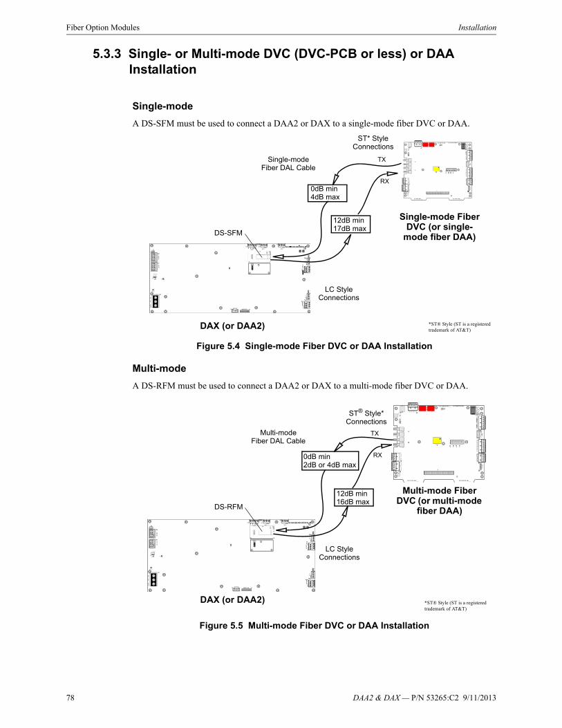
78 DAA2 & DAX — P/N 53265:C2 9/11/2013
Fiber Option Modules Installation
5.3.3 Single- or Multi-mode DVC (DVC-PCB or less) or DAA Installation
Single-mode
A DS-SFM must be used to connect a DAA2 or DAX to a single-mode fiber DVC or DAA.
Figure 5.4 Single-mode Fiber DVC or DAA Installation
Multi-mode
A DS-RFM must be used to connect a DAA2 or DAX to a multi-mode fiber DVC or DAA.
Figure 5.5 Multi-mode Fiber DVC or DAA Installation
DAX (or DAA2)
DS-SFM
Single-modeFiber DAL Cable
Single-mode Fiber DVC (or single-
mode fiber DAA)
ST* Style Connections
LC Style Connections
*ST® Style (ST is a registered trademark of AT&T)
12dB min17dB max
0dB min4dB max
RX
TX
DAX (or DAA2)
DS-RFM
Multi-modeFiber DAL Cable
Multi-mode Fiber DVC (or multi-mode
fiber DAA)
ST® Style* Connections
LC Style Connections
*ST® Style (ST is a registered trademark of AT&T)
0dB min2dB or 4dB max
12dB min16dB max
RX
TX
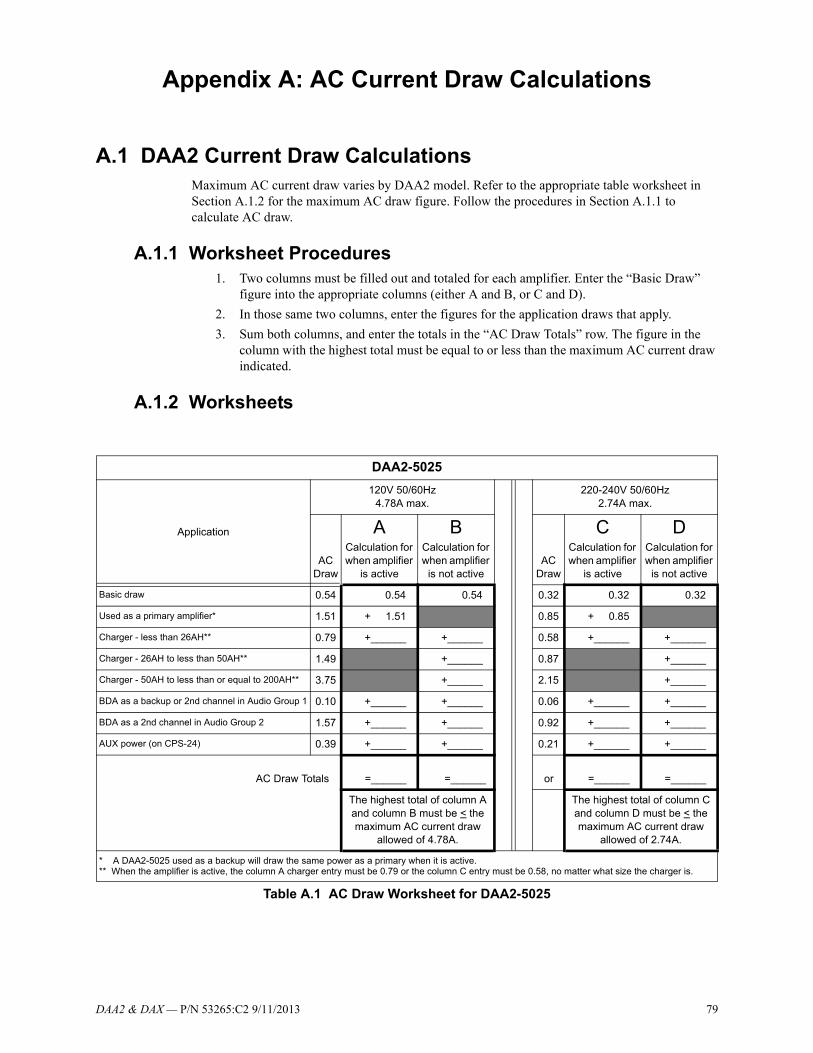
DAA2 & DAX — P/N 53265:C2 9/11/2013 79
Appendix A: AC Current Draw Calculations
A.1 DAA2 Current Draw CalculationsMaximum AC current draw varies by DAA2 model. Refer to the appropriate table worksheet in Section A.1.2 for the maximum AC draw figure. Follow the procedures in Section A.1.1 to calculate AC draw.
A.1.1 Worksheet Procedures1. Two columns must be filled out and totaled for each amplifier. Enter the “Basic Draw”
figure into the appropriate columns (either A and B, or C and D).
2. In those same two columns, enter the figures for the application draws that apply.
3. Sum both columns, and enter the totals in the “AC Draw Totals” row. The figure in the column with the highest total must be equal to or less than the maximum AC current draw indicated.
A.1.2 Worksheets
DAA2-5025
Application
120V 50/60Hz4.78A max.
220-240V 50/60Hz2.74A max.
AC Draw
ACalculation for when amplifier
is active
BCalculation for when amplifier
is not activeAC
Draw
CCalculation for when amplifier
is active
DCalculation for when amplifier
is not active
Basic draw 0.54 0.54 0.54 0.32 0.32 0.32
Used as a primary amplifier* 1.51 + 1.51 0.85 + 0.85
Charger - less than 26AH** 0.79 +______ +______ 0.58 +______ +______
Charger - 26AH to less than 50AH** 1.49 +______ 0.87 +______
Charger - 50AH to less than or equal to 200AH** 3.75 +______ 2.15 +______
BDA as a backup or 2nd channel in Audio Group 1 0.10 +______ +______ 0.06 +______ +______
BDA as a 2nd channel in Audio Group 2 1.57 +______ +______ 0.92 +______ +______
AUX power (on CPS-24) 0.39 +______ +______ 0.21 +______ +______
AC Draw Totals =______ =______ or =______ =______
The highest total of column A and column B must be < the maximum AC current draw
allowed of 4.78A.
The highest total of column C and column D must be < the maximum AC current draw
allowed of 2.74A.
* A DAA2-5025 used as a backup will draw the same power as a primary when it is active.** When the amplifier is active, the column A charger entry must be 0.79 or the column C entry must be 0.58, no matter what size the charger is.
Table A.1 AC Draw Worksheet for DAA2-5025
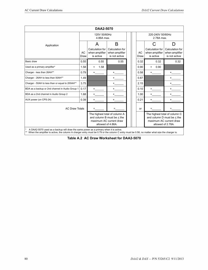
80 DAA2 & DAX — P/N 53265:C2 9/11/2013
AC Current Draw Calculations DAA2 Current Draw Calculations
DAA2-5070
Application
120V 50/60Hz4.86A max.
220-240V 50/60Hz2.78A max.
AC Draw
ACalculation for when amplifier
is active
BCalculation for when amplifier
is not activeAC
Draw
CCalculation for when amplifier
is active
DCalculation for when amplifier
is not active
Basic draw 0.55 0.55 0.55 0.32 0.32 0.32
Used as a primary amplifier* 1.58 + 1.58 0.90 + 0.90
Charger - less than 26AH** 0.79 +______ +______ 0.58 +______ +______
Charger - 26AH to less than 50AH** 1.49 +______ 0.87 +______
Charger - 50AH to less than or equal to 200AH** 3.75 +______ 2.15 +______
BDA as a backup or 2nd channel in Audio Group 1 0.17 +______ +______ 0.10 +______ +______
BDA as a 2nd channel in Audio Group 2 1.68 +______ +______ 1.00 +______ +______
AUX power (on CPS-24) 0.39 +______ +______ 0.21 +______ +______
AC Draw Totals =______ =______ or =______ =______
The highest total of column A and column B must be < the maximum AC current draw
allowed of 4.86A.
The highest total of column C and column D must be < the maximum AC current draw
allowed of 2.78A.
* A DAA2-5070 used as a backup will draw the same power as a primary when it is active.** When the amplifier is active, the column A charger entry must be 0.79 or the column C entry must be 0.58, no matter what size the charger is.
Table A.2 AC Draw Worksheet for DAA2-5070

DAA2 & DAX — P/N 53265:C2 9/11/2013 81
DAX Current Draw Calculations AC Current Draw Calculations
A.2 DAX Current Draw CalculationsMaximum AC draw varies by DAX model. Refer to the appropriate table worksheet in Section A.2.2 for the maximum AC draw figure. Follow the procedures in Section A.2.1 to calculate AC draw.
A.2.1 Worksheet Procedures1. Enter the “Basic Draw” figure into the appropriate column (either A or B).
2. In that same column, enter the figures for the application draws that apply.
3. Sum the column, and enter the total in the “Total AC Draw” row. The total must be equal or less than the maximum indicated.
A.2.2 Worksheets
DAA2-7525
Application
120V 50/60Hz4.1A max.
220-240V 50/60Hz2.51A max.
AC Draw
ACalculation for when amplifier
is active
BCalculation for when amplifier
is not activeAC
Draw
CCalculation for when amplifier
is active
DCalculation for when amplifier
is not active
Basic draw 0.54 0.54 0.54 0.32 0.32 0.32
Used as a primary amplifier* 2.28 + 2.28 1.34 + 1.34
Charger - less than 26AH** 0.79 +______ +______ 0.58 +______ +______
Charger - 26AH to less than 50AH** 1.49 +______ 0.87 +______
BDA as a backup or 2nd channel in Audio Group 1. 0.10 +______ +______ 0.06 +______ +______
AUX power (on CPS-24) 0.39 +______ +______ 0.21 +______ +______
AC Draw Totals =______ =______ or =______ =______
The highest total of column A and column B must be < the maximum AC current draw
allowed of 4.1A.
The highest total of column C and column D must be < the maximum AC current draw
allowed of 2.51A.
* A DAA2-7525 used as a backup will draw the same power as a primary when it is active.** When the amplifier is active, the column A charger entry must be 0.79 or the column C entry must be 0.58, no matter what size the charger is.
Table A.3 AC Draw Worksheet for DAA2-7525
DAX-5025
Application
120V 50/60Hz2.09A max.
220-240V 50/60Hz1.18A max.
AC Draw A AC Draw BBasic draw 0.50 0.50 0.29 0.29
Used as a primary amplifier* 1.39 +______ 0.79 +______
BDA as a backup 0.20 +______ 0.10 +______
Table A.4 AC Draw Worksheet for DAX-5025
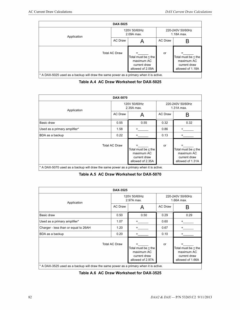
82 DAA2 & DAX — P/N 53265:C2 9/11/2013
AC Current Draw Calculations DAX Current Draw Calculations
Total AC Draw =______Total must be < the
maximum AC current draw
allowed of 2.09A
or =______Total must be < the
maximum AC current draw
allowed of 1.18A
* A DAX-5025 used as a backup will draw the same power as a primary when it is active.
DAX-5025
Application
120V 50/60Hz2.09A max.
220-240V 50/60Hz1.18A max.
AC Draw A AC Draw B
Table A.4 AC Draw Worksheet for DAX-5025
DAX-5070
Application
120V 50/60Hz2.35A max.
220-240V 50/60Hz1.31A max.
AC Draw A AC Draw BBasic draw 0.55 0.55 0.32 0.32
Used as a primary amplifier* 1.58 +______ 0.86 +______
BDA as a backup 0.22 +______ 0.13 +______
Total AC Draw =______
Total must be < the maximum AC current draw
allowed of 2.35A
or =______Total must be < the
maximum AC current draw
allowed of 1.31A
* A DAX-5070 used as a backup will draw the same power as a primary when it is active.
Table A.5 AC Draw Worksheet for DAX-5070
DAX-3525
Application
120V 50/60Hz2.97A max.
220-240V 50/60Hz1.66A max.
AC Draw A AC Draw BBasic draw 0.50 0.50 0.29 0.29
Used as a primary amplifier* 1.07 +______ 0.60 +______
Charger - less than or equal to 26AH 1.20 +______ 0.67 +______
BDA as a backup 0.20 +______ 0.10 +______
Total AC Draw =______
Total must be < the maximum AC current draw
allowed of 2.97A
or =______Total must be < the
maximum AC current draw
allowed of 1.66A
* A DAX-3525 used as a backup will draw the same power as a primary when it is active.
Table A.6 AC Draw Worksheet for DAX-3525
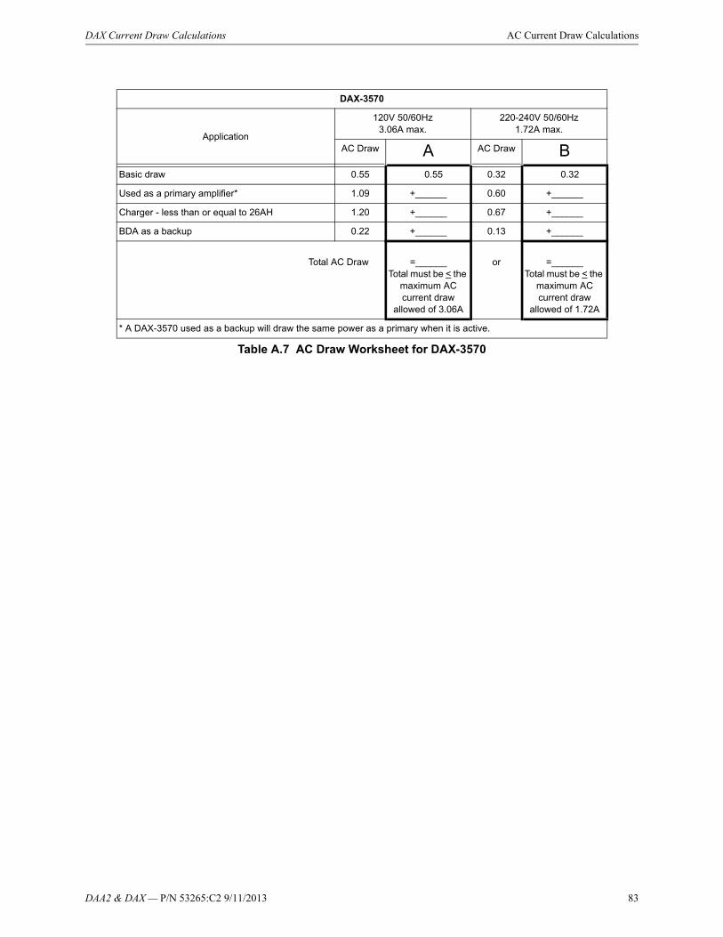
DAA2 & DAX — P/N 53265:C2 9/11/2013 83
DAX Current Draw Calculations AC Current Draw Calculations
DAX-3570
Application
120V 50/60Hz3.06A max.
220-240V 50/60Hz1.72A max.
AC Draw A AC Draw BBasic draw 0.55 0.55 0.32 0.32
Used as a primary amplifier* 1.09 +______ 0.60 +______
Charger - less than or equal to 26AH 1.20 +______ 0.67 +______
BDA as a backup 0.22 +______ 0.13 +______
Total AC Draw =______
Total must be < the maximum AC current draw
allowed of 3.06A
or =______Total must be < the
maximum AC current draw
allowed of 1.72A
* A DAX-3570 used as a backup will draw the same power as a primary when it is active.
Table A.7 AC Draw Worksheet for DAX-3570

84 DAA2 & DAX — P/N 53265:C2 9/11/2013
Appendix B: Battery Calculations
B.1 DAA2 Battery Calculations
Description Column AAmps in Standby
Column BAmps in Alarm
QTY X current draw = Total QTY X current draw = Total
DAA2-50251,2 or DAA2-75251,2
[ ] X [ 0.400A ] = [ ] X [ 0.500A ] =
DAA2-50701,2 [ ] X [ 0.400A ] = [ ] X [ 0.550A ] =
BDA-25V [ ] X [ 0.100A ] = [ ] X [ 0.225A ] =
BDA-70V [ ] X [ 0.100A ] = [ ] X [ 0.235A ] =
AUX 24V [ ] X [ 0.500A ] = [ ] X [ 0.500A ] =
RM-13 [ ] X [ 0.015A ] = [ ] X [ 0.075A ] =
DS-FM (all models) [ ] X [ 0.06A ] = [ ] X [ 0.06A ] =
Speakers:
1/4 watt [ ] X [ 0.016A ] =
1/2 watt [ ] X [ 0.032A ] =
3/4 watt [ ] X [ 0.0485A ] =
1 watt [ ] X [ 0.064A ] =
2 watt [ ] X [ 0.132A ] =
ACT-252 [ ] X [ 0.0015A ] =
ACT-702 [ ] X [ 0.002A ] =
Other _______ [ ] X[ ] = [ ] X [ ] =
Total Column A _______ Total Column B _______
1Includes FFT Riser Draw2Riser To Additional Amplifiers” mode is always active and driving the risers with a supervision tone. For this reason, it is never in standby, and the figures in Column B should be used for all calculations.3Alarm draw is for activated microphone.
Table B.1 Current Draw Calculations Per DAA2
NOTE: Battery Sharing - When batteries are shared by two or more DAA2s, Table B.1 must be completed for each DAA2. The totals for Columns A and Columns B must be summed and entered into Table B.2 where indicated.

DAA2 & DAX — P/N 53265:C2 9/11/2013 85
DAA2 Battery Calculations Battery Calculations
Table B.3 Battery Size Requirements
Load Totals Multiplied By Time Equals Secondary Amp Hour Totals
Enter total from Column A in Table B.1. (Standby Load)
[ ] XRequired Secondary Non-
fire Alarm Standby Time (24 or 60 hours)
[ ] = [ ]Non-fire Alarm
Secondary Standby Amp Hours
Enter total from Column B in Table B.1. (Alarm Load)
[ ] XRequired Fire Alarm Time
in Decimal Form*[ ] = [ ]
Secondary Fire Alarm Amp Hour Requirement
Sum column for Total Secondary Ampere Hours (AH) Calculated =
Multiply by the derating factor X 1.2 = [ ] Total Secondary Ampere Hours Required
*Following are decimal conversions for standard numbers of minutes:
5 minutes10 minutes15 minutes30 minutes60 minutes
0.0840.1670.2500.501.0
Standby operating times:• NFPA 72 Local, Proprietary, Auxiliary, Remote Station, and Central Station systems require 24 hours of standby power followed
by 5 minutes in alarm.• Some jurisdictions require 60 hours of standby power followed by 5 minutes in alarm for Auxiliary and Remote Station systems,
based on previous NFPA 72 requirements.• 24 hours of standby/supervisory condition followed by 2 hours of alarm.• The following battery derating factors must be used for Canadian installations. Derating factors are subject to local AHJ approval.
- For 12 - 26 AH capacity, use derating factor of 1.2.- For 55 AH capacity, use derating factor of 1.8.- For 100 - 200 AH capacity, use derating factor of 2.5.
Table B.2 Secondary Power Standby and Fire Alarm Load
Battery Size Voltage Rating Required Number Model Number
7 AH 12 volts Two BAT-1270
12 AH 12 volts Two BAT-12120
26 AH 12 volts Two BAT-12260
55 AH 12 volts Two BAT-12550
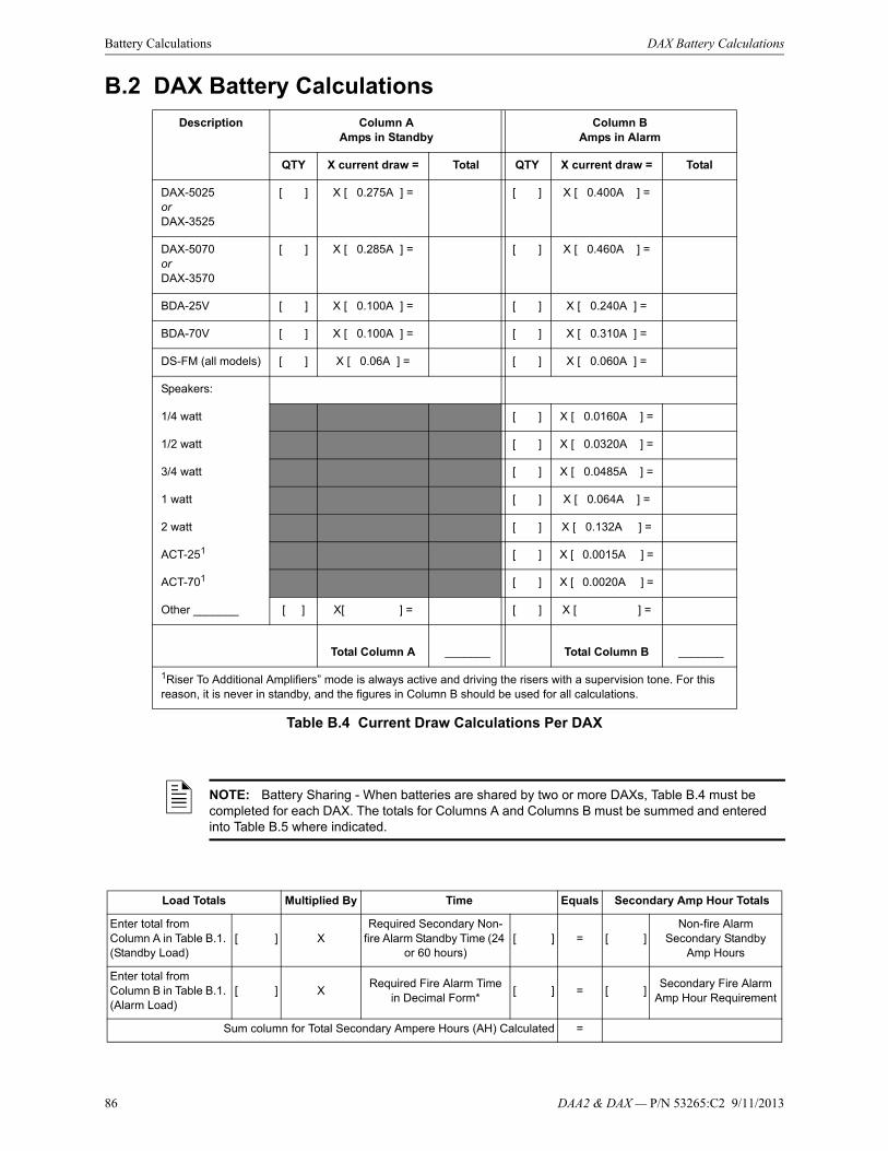
86 DAA2 & DAX — P/N 53265:C2 9/11/2013
Battery Calculations DAX Battery Calculations
B.2 DAX Battery Calculations
Description Column AAmps in Standby
Column BAmps in Alarm
QTY X current draw = Total QTY X current draw = Total
DAX-5025or DAX-3525
[ ] X [ 0.275A ] = [ ] X [ 0.400A ] =
DAX-5070or DAX-3570
[ ] X [ 0.285A ] = [ ] X [ 0.460A ] =
BDA-25V [ ] X [ 0.100A ] = [ ] X [ 0.240A ] =
BDA-70V [ ] X [ 0.100A ] = [ ] X [ 0.310A ] =
DS-FM (all models) [ ] X [ 0.06A ] = [ ] X [ 0.060A ] =
Speakers:
1/4 watt [ ] X [ 0.0160A ] =
1/2 watt [ ] X [ 0.0320A ] =
3/4 watt [ ] X [ 0.0485A ] =
1 watt [ ] X [ 0.064A ] =
2 watt [ ] X [ 0.132A ] =
ACT-251 [ ] X [ 0.0015A ] =
ACT-701 [ ] X [ 0.0020A ] =
Other _______ [ ] X[ ] = [ ] X [ ] =
Total Column A _______ Total Column B _______
1Riser To Additional Amplifiers” mode is always active and driving the risers with a supervision tone. For this reason, it is never in standby, and the figures in Column B should be used for all calculations.
Table B.4 Current Draw Calculations Per DAX
NOTE: Battery Sharing - When batteries are shared by two or more DAXs, Table B.4 must be completed for each DAX. The totals for Columns A and Columns B must be summed and entered into Table B.5 where indicated.
Load Totals Multiplied By Time Equals Secondary Amp Hour Totals
Enter total from Column A in Table B.1. (Standby Load)
[ ] XRequired Secondary Non-
fire Alarm Standby Time (24 or 60 hours)
[ ] = [ ]Non-fire Alarm
Secondary Standby Amp Hours
Enter total from Column B in Table B.1. (Alarm Load)
[ ] XRequired Fire Alarm Time
in Decimal Form*[ ] = [ ]
Secondary Fire Alarm Amp Hour Requirement
Sum column for Total Secondary Ampere Hours (AH) Calculated =
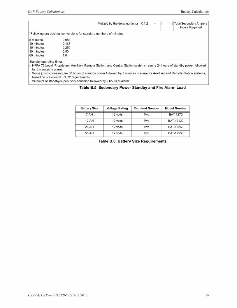
DAA2 & DAX — P/N 53265:C2 9/11/2013 87
DAX Battery Calculations Battery Calculations
Table B.5 Secondary Power Standby and Fire Alarm Load
Table B.6 Battery Size Requirements
Multiply by the derating factor X 1.2 = [ ] Total Secondary Ampere Hours Required
*Following are decimal conversions for standard numbers of minutes:
5 minutes10 minutes15 minutes30 minutes60 minutes
0.0840.1670.2500.501.0
Standby operating times:• NFPA 72 Local, Proprietary, Auxiliary, Remote Station, and Central Station systems require 24 hours of standby power followed
by 5 minutes in alarm.• Some jurisdictions require 60 hours of standby power followed by 5 minutes in alarm for Auxiliary and Remote Station systems,
based on previous NFPA 72 requirements.• 24 hours of standby/supervisory condition followed by 2 hours of alarm.
Battery Size Voltage Rating Required Number Model Number
7 AH 12 volts Two BAT-1270
12 AH 12 volts Two BAT-12120
26 AH 12 volts Two BAT-12260
55 AH 12 volts Two BAT-12550

88 DAA2 & DAX — P/N 53265:C2 9/11/2013
Appendix C: DAA Digital Audio Amplifiers
C.1 Overview
C.1.1 Description
The DAA Digital Audio Amplifiers are multi-featured amplifiers with digital audio functionality. They are designed for a networked or non-networked environment with the DVC Digital Voice Command.
DAA models are compatible with other types of DAL devices (e.g. DAA2, DAX) on a wire, fiber, or mixed wire/fiber digital audio loop. A DS-RFM (for multi-mode DAAs) or DS-SFM (for single-mode DAAs) is required for a fiber DAA used on a DAL with other types of DAL devices.
NOTE: The term DAA is used in this manual to refer to all the model versions listed in the bullets below this note. Individual part numbers are used to distinguish features or functions that differ.
50 Watt Digital Audio Amplifiers
SpeakerCircuit Output Medium
DAA-5025 (120 VAC) 25RMS Wire
DAA-5025E (220-240 VAC) 25RMS Wire
DAA-5070 (120 VAC) 70RMS Wire
DAA-5070E (220-240 VAC) 70RMS Wire
DAA-5025F (120 VAC) 25RMS Multi-mode fiber
DAA-5025EF (220-240 VAC) 25RMS Multi-mode fiber
DAA-5070F (120 VAC) 70RMS Multi-mode fiber
DAA-5070EF (220-240 VAC) 70RMS Multi-mode fiber
DAA-5025SF (120 VAC) 25RMS Single-mode fiber
DAA-5025ESF (220-240 VAC) 25RMS Single-mode fiber
DAA-5070SF (120 VAC) 70RMS Single-mode fiber
DAA-5070ESF (220-240 VAC) 70RMS Single-mode fiber
75 Watt Digital Audio Amplifiers
SpeakerCircuit Output Medium
DAA-7525 (120 VAC) 25RMS Wire
DAA-7525E (220-240 VAC) 25RMS Wire
DAA-7525F (120 VAC) 25RMS Multi-mode fiber
DAA-7525EF (220-240 VAC) 25RMS Multi-mode fiber
DAA-7525SF (120 VAC) 25RMS Single-mode fiber
DAA-7525ESF (220-240 VAC) 25RMS Single-mode fiber
Table C.1 Digital Audio Amplifier Models

DAA2 & DAX — P/N 53265:C2 9/11/2013 89
Overview DAA Digital Audio Amplifiers
Figure C.1 gives a simplified illustration of DAAs and their positions in the Digital Audio Loop (DAL) of a DVC.
Figure C.1 DAL Block Diagram
C.1.2 Features
The DAA audio amplifiers have the following features:
• 50W total output power at 25VRMS (all DAA-5025 model versions) or 70 VRMS (all DAA-5070 model versions).
• 75W total output power at 25VRMS (all DAA-7525 model versions).
• Two Class A (Style Z) connections for high-level audio output, or alternately, four Class B (Style Y) connections, which dynamically share the 50W output capability.
• Audio output activation via network control-by-event equations resident within the DVC.
• Isolated alarm bus input, to be used for backup activation of alarm messages when normal digital communication is lost.
• Amplifies one channel of digital audio and distributes it on up to four outputs (50W maximum).
• Auxiliary input for 12VP-P analog low-level AMG-1 type audio sources.
• Auxiliary input for 1.6Vp-p max. for each circuit when both AUXA L and AUXA R are used, or 3.2Vp-p max. for one when only one circuit (AUXA L or AUXR) is used, to be used for background music input, an interface with a telephone paging source, or other compatible audio sources. Includes user audio level adjustment feature.
• Uploads and downloads via the DVC.
• Up to 106 seconds of Backup Digital message storage (Emergency tone, Non-Emergency tone, and FFT busy tone) for use in the event of communication loss- either standard quality or high quality, from the VeriFire Tools message library or created by the installer.
• Battery charger (50 watt DAAs only) and power supply capable of supporting up to 55AH batteries.
• Relay contacts that will activate on a trouble condition.
• Backup amplifier function.
• Programmable through VeriFire Tools.
• Meets UL requirements for 800 Hz to 2.8 KHz bandwidth.Meets ULC requirements for 400 Hz to 4 KHz bandwidth.
DVC DAA1
DAA2
DAA32
Optional Class A (Style 7) return
To panel or network connection
Digital Audio Loop (DAL)
NOTE:Speaker placement must be given careful consideration when planning an audio system.
• Place speakers from different DALs (Digital Audio Loops) so they are not within the audible areas of other DALs.
• Carefully consider the audible range of speakers within a DAL; overlapping audio messages can be confusing.

90 DAA2 & DAX — P/N 53265:C2 9/11/2013
DAA Digital Audio Amplifiers Overview
C.1.3 Specifications
DAA-PS Power Supply Board
AC Power - TB1
115-120 VAC 60 Hz input, 4.5 A max.
220-240 VAC 50/60 Hz input, 2.3 A max. (“E” versions)
Recommended wiring: 12-14 AWG (1.6mm O.D.) with 600 VAC insulation.
Battery Connections - TB3
Supplied cable connections to batteries for CAB-4 and CHS-BH1. For battery sharing, use 12 AWG either in the same cabinet or in conduit for no more than 20 ft. (6.09 m).
Battery Charger (50 Watt Boards Only)
Current-limited sealed lead acid battery charger which charges two 12 volt 7-55 AH batteries in series.
Charger current: Up to 1.0 A or 5.5 A setting based on battery size programming.
Charger voltage: 27.6 VDC.
For battery calculation worksheet and standby operating times, refer to “Battery Calculations” on page 121.
Utilizes wire sizes 12-18 AWG.
Battery Fuse (F2) 15A, (Notifier p/n 12057).
DAA-5025/70 and DAA-7525 Boards
Digital Audio Ports A and B - TB2, TB3
Refer to Table C.2, and also to the Wiring Guide, p/n 52916ADD, for other acceptable wire types.)
EIA-485 format.
Power-limited (Class 2).
Single- and Multi-mode Fiber-Optic Digital Audio Ports - RXA,TXA, RXB and TXB (J100, J101, J102, and J103)
ST® Style (ST is a registered trademark of AT&T).
Supervised.
Fiber optic cable, multi-mode: 50/125 or 62.5/125 micrometers.
Fiber optic cable, single-mode: 9/125 micrometers.
Attenuation of cabling between two nodes (fiber-optic circuits are point-to-point) must not exceed the Maximum attenuation, specified below.
To determine attenuation:
NOTE: DAA-75 products do not have an onboard battery charger. A UL 864 listed power supply rated for the battery requirements of the specific application is suitable for charging purposes.
Cable TypeMaximum Distance
between Ports
Belden 5320UJ (18 AWG, TP) FPL 1900 ft (609.6 m)
Genesis 4050 (18 AWG, TP) FPL 1000 ft (305.8 m)
Table C.2 Recommended Digital Audio Port Cable Types
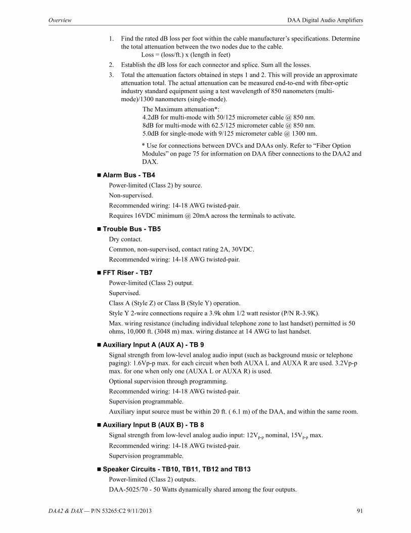
DAA2 & DAX — P/N 53265:C2 9/11/2013 91
Overview DAA Digital Audio Amplifiers
1. Find the rated dB loss per foot within the cable manufacturer’s specifications. Determine the total attenuation between the two nodes due to the cable. Loss = (loss/ft.) x (length in feet)
2. Establish the dB loss for each connector and splice. Sum all the losses.
3. Total the attenuation factors obtained in steps 1 and 2. This will provide an approximate attenuation total. The actual attenuation can be measured end-to-end with fiber-optic industry standard equipment using a test wavelength of 850 nanometers (multi-mode)/1300 nanometers (single-mode).
The Maximum attenuation*:4.2dB for multi-mode with 50/125 micrometer cable @ 850 nm.8dB for multi-mode with 62.5/125 micrometer cable @ 850 nm.5.0dB for single-mode with 9/125 micrometer cable @ 1300 nm.
* Use for connections between DVCs and DAAs only. Refer to “Fiber Option Modules” on page 75 for information on DAA fiber connections to the DAA2 and DAX.
Alarm Bus - TB4
Power-limited (Class 2) by source.
Non-supervised.
Recommended wiring: 14-18 AWG twisted-pair.
Requires 16VDC minimum @ 20mA across the terminals to activate.
Trouble Bus - TB5
Dry contact.
Common, non-supervised, contact rating 2A, 30VDC.
Recommended wiring: 14-18 AWG twisted-pair.
FFT Riser - TB7
Power-limited (Class 2) output.
Supervised.
Class A (Style Z) or Class B (Style Y) operation.
Style Y 2-wire connections require a 3.9k ohm 1/2 watt resistor (P/N R-3.9K).
Max. wiring resistance (including individual telephone zone to last handset) permitted is 50 ohms, 10,000 ft. (3048 m) max. wiring distance at 14 AWG to last handset.
Auxiliary Input A (AUX A) - TB 9
Signal strength from low-level analog audio input (such as background music or telephone paging): 1.6Vp-p max. for each circuit when both AUXA L and AUXA R are used. 3.2Vp-p max. for one when only one (AUXA L or AUXA R) is used.
Optional supervision through programming.
Recommended wiring: 14-18 AWG twisted-pair.
Supervision programmable.
Auxiliary input source must be within 20 ft. ( 6.1 m) of the DAA, and within the same room.
Auxiliary Input B (AUX B) - TB 8
Signal strength from low-level analog audio input: 12Vp-p nominal, 15Vp-p max.
Recommended wiring: 14-18 AWG twisted-pair.
Supervision programmable.
Speaker Circuits - TB10, TB11, TB12 and TB13
Power-limited (Class 2) outputs.
DAA-5025/70 - 50 Watts dynamically shared among the four outputs.
92 DAA2 & DAX — P/N 53265:C2 9/11/2013
DAA Digital Audio Amplifiers Overview
DAA-7525 - 75 Watts dynamically shared among the four outputs.
Supervision determined by programming.
25VRMS - DAA-5025/DAA-7525 speaker circuits, 70VRMS - DAA-5070 speaker circuits
Recommended wiring: 12-18 AWG twisted -pair (shielded recommended).
Class B (Style Y) or Class A (Style Z):
Class B requires 20k end-of-line resistors (included, P/N ELR-20K).
Class A requires 10k end-of-line resistors (included, P/N R-10K) on the return.

DAA2 & DAX — P/N 53265:C2 9/11/2013 93
Overview DAA Digital Audio Amplifiers
C.1.4 DAA Board Layouts
Wire Versions
Connection Locations
Wire DAAs are each comprised of two boards; a larger rear board, and a smaller front power supply board. Figure C.2 below shows the layouts for these boards.
Figure C.2 Connection Locations for Wire Version DAA Boards
RISER (+) OUT
RISER (-) OUTRISER SHIELD OUT
AUXA R +AUXA R -AUXA L +AUXA L -
ALM INREF IN
ALM OUTREF OUT
RISER (+) RTN
RISER (-) RTNRISER SHIELD RTN
OUT 1 SHLDOUT 1-OUT 1+
TROUBLE OUT NOTROUBLE OUT NC
TROUBLE OUT COM
BKIN 1+BKIN 1-BKIN 1 SHLDBKOUT 1+BKOUT 1-BKOUT 1 SHLD
TB10BACKUP
CKT 1
BKOUT 2 SHLDBKOUT 2-BKOUT 2+BKIN 2 SHLDBKIN 2-BKIN 2+
TB9Refer to page 110
TB4 - AlarmRefer to page 106
TB7 - FFT RiserRefer to page 109 TB10, TB11, TB12, TB13
Speaker CircuitsRefer to page 111
TB10SPKR CKT 1
TB5Refer to page 107
OUT 2 SHLDOUT 2-OUT 2+
BA
CK
UP
C
KT
2S
PK
R
CK
T 2
BKOUT 3 SHLDBKOUT 3-BKOUT 3+BKIN 3 SHLDBKIN 3-BKIN 3+
OUT 3 SHLDOUT 3-OUT 3+
BA
CK
UP
C
KT
3S
PK
R
CK
T 3
BKOUT 4 SHLDBKOUT 4-BKOUT 4+BKIN 4 SHLDBKIN 4-BKIN 4+
OUT 4 SHLDOUT 4-OUT 4+
BA
CK
UP
C
KT
4S
PK
R
CK
T 4
USB Connector
J2Future Use
TB11
TB13
DAPA + DAPA - DAPA REF
DAPB + DAPB - DAPB REF
AUXB +AUXB -AUXB SHLD
TB2 - Digital Audio Port ARefer to page 108
TB3 - Digital Audio Port BRefer to page 108
DAA Board
DAA-PS Power Supply Board
EARTHNEUTRAL
HOT
TB1AC INPUTRefer to page 102
TB3BATT CONNRefer to page 103 BATT+
BATT-TB8AUX BRefer to page 110
DA
Ap
wrs
upb
d.w
mf
DA
AB
oar
d1
.wm
f
TB12
TB2Future Use
Note: If TB5 is a 3--screw terminal, the DAA board is PCB or higher.
DAA board ID - DAA boards can be identified by the silkscreening on the board. This example shows a B board. It is silkscreened with PCB
Dotted rectangular area indicates case.
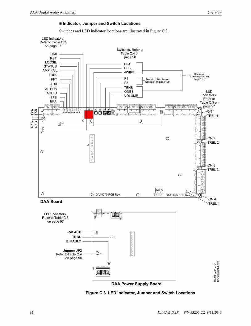
94 DAA2 & DAX — P/N 53265:C2 9/11/2013
DAA Digital Audio Amplifiers Overview
Indicator, Jumper and Switch Locations
Switches and LED indicator locations are illustrated in Figure C.3.
Figure C.3 LED Indicator, Jumper and Switch Locations
DAA Board
DAA Power Supply Board
EFAEFB
AUX
AL BUS
FFTTRBL
AMP FAIL
LED Indicators. Refer to Table C.3
on page 97Switches. Refer to
Table C.4 on page 98
ONESTENS
F2F1
VOLUME
TRBL 1ON 1
TRBL 2ON 2
TRBL 3ON 3
TRBL 4ON 4
LED Indicators. Refer to
Table C.3 on page 97
LED Indicators. Refer to Table C.3
on page 97D
AA
pwrs
upbd
.wm
fD
AA
Boa
rd1.
wm
f
See also “Pushbutton Controls” on page 120
See also “Configuration” on
page 119
EFBEFA
4WIRE
STATUSLOCSIL
RST
RX
AT
XA
RX
BT
XB
AUDIO
+5V AUX
TRBLE. FAULT
Jumper JP2Refer toTable C.4
on page 98
USB

DAA2 & DAX — P/N 53265:C2 9/11/2013 95
Overview DAA Digital Audio Amplifiers
Fiber Versions
Connection Locations
Fiber DAAs are each comprised of two boards; a larger rear board, and a smaller front power supply board. Figure C.4 below shows the layout for the larger rear board. The connections for the smaller front board, the DAA-PS, are the same for all DAAs, and are illustrated in Figure C.2, “Connection Locations for Wire Version DAA Boards”.
Figure C.4 Connection Locations for Fiber Version DAA Boards
RISER (+) OUT
RISER (-) OUTRISER SHIELD OUT
AUXA R +AUXA R -AUXA L +AUXA L -
ALM INREF IN
ALM OUTREF OUT
RISER (+) RTN
RISER (-) RTNRISER SHIELD RTN
OUT 1 SHLDOUT 1-OUT 1+
TROUBLE OUT NOTROUBLE OUT NC
TROUBLE OUT COM
BKIN 1+BKIN 1-BKIN 1 SHLDBKOUT 1+BKOUT 1-BKOUT 1 SHLD
TB10BACKUP
CKT 1
BKOUT 2 SHLDBKOUT 2-BKOUT 2+BKIN 2 SHLDBKIN 2-BKIN 2+
TB9Refer to page 110
TB4 - AlarmRefer to page 106
TB7 - FFT RiserRefer to page 109 TB10, TB11, TB12, TB13
Speaker CircuitsRefer to page 111
TB10SPKR CKT 1
TB5Refer to page 107
OUT 2 SHLDOUT 2-OUT 2+
BA
CK
UP
C
KT
2S
PK
R
CK
T 2
BKOUT 3 SHLDBKOUT 3-BKOUT 3+BKIN 3 SHLDBKIN 3-BKIN 3+
OUT 3 SHLDOUT 3-OUT 3+
BA
CK
UP
C
KT
3S
PK
R
CK
T 3
BKOUT 4 SHLDBKOUT 4-BKOUT 4+BKIN 4 SHLDBKIN 4-BKIN 4+
OUT 4 SHLDOUT 4-OUT 4+
BA
CK
UP
C
KT
4S
PK
R
CK
T 4
TB11
TB13
AUXB +AUXB -AUXB SHLD
DAA Board
TB8AUX BRefer to page 110
DA
A_
f_B
brd
1.w
mf
TB12
USB Connector J2Future Use
TXA RXA TXB RXB
DAA board ID - DAA boards can be identified by the silkscreening on the board. This example shows a B board. It is silkscreened with PCB
Note: If TB5 is a 3--screw terminal, the DAA board is PCB or higher.

96 DAA2 & DAX — P/N 53265:C2 9/11/2013
DAA Digital Audio Amplifiers Overview
Indicator and Switch Locations
Switches and LED indicator locations are illustrated in Figure C.5. The connections for the smaller front board, the DAA-PS, are the same for all DAAs, and are illustrated in Figure C.3, “LED Indicator, Jumper and Switch Locations”.
Figure C.5 LED Indicator and Switch Locations, Fiber Boards
Indicators
Diagnostic colored LEDs indicate various conditions and troubles. Table C.3 lists and describes each.
DAA Board
LED Indicators. Refer to Table C.3
on page 97
Switches. Refer to Table C.4 on
page 98
ONESTENS
F2F1
VOLUME
TRBL 1ON 1
TRBL 2ON 2
TRBL 3ON 3
TRBL 4
ON 4
LED Indicators. Refer to
Table C.3 on page 97
DA
A_
f_b
rd1.
wm
f
See also “Pushbutton Controls” on page 120
See also “Configuration” on
page 119
4WIRE
RX
AT
XA
RX
BT
XB
LINK BRX OK
LINK ARX OK
AUXAL BUS
FFT
TRBLAMP FAIL
STATUSLOCSILRSTAUDIO
USB
DAA Board
LED Name Color Description LED #
EFB Yellow Illuminates steadily when an earth fault has been detected at digital audio port DAP B. LED is on wire versions only.
1
EFA Yellow Illuminates steadily when an earth fault has been detected at digital audio port DAP A. LED is on wire versions only.
2
AMP FAIL Yellow Illuminates steadily while audio amplifier failure detected. 4
ON 4 Green Illuminates steadily while analog signal is on speaker circuit 43, or while 200Hz tone is on speaker circuit 4.
5

DAA2 & DAX — P/N 53265:C2 9/11/2013 97
Overview DAA Digital Audio Amplifiers
Table C.3 LED Indicators
ON 3 Green Illuminates steadily while analog signal is on speaker circuit 3, or while 200Hz tone is on speaker circuit 3.
6
ON 2 Green Illuminates steadily while analog signal is on speaker circuit 2, or while 200Hz tone is on speaker circuit 2.
7
ON 1 Green Illuminates steadily while analog signal is on speaker circuit 1, or while 200Hz tone is on speaker circuit 1.
8
TRBL Yellow Blinks when there is an unacknowledged trouble, illuminates steadily when a trouble is acknowledged but unresolved.
9
AL BUS Red Illuminates steadily while alarm bus input is active. 10
AUX Green Illuminates while audio detected on either AUX IN A or AUX IN B. 11
FFT Green Illuminates steadily when it has been granted a digital phone channel. Flashes when a DAA requests a phone channel.
12
AUDIO Green OFF - No audio signal is present.Fast blink - The DAA is receiving audio from the DVC.Slow blink - The DAA is playing audio from stored backup tones.Steady - The DAA is playing audio from its AUX input.
13
TRBL 1 Yellow Illuminates steadily while a short is detected on speaker circuit 1. Blinks slowly while an open is detected. Blinks fast when this speaker circuit is disabled.
14
TRBL 2 Yellow Illuminates steadily while a short is detected on speaker circuit 2. Blinks slowly while an open is detected. Blinks fast when this speaker circuit is disabled.
15
TRBL 3 Yellow Illuminates steadily while a short is detected on speaker circuit 3. Blinks slowly while an open is detected. Blinks fast when this speaker circuit is disabled.
16
TRBL 4 Yellow Illuminates steadily while a short is detected on speaker circuit 4. Blinks slowly while an open is detected. Blinks fast when this speaker circuit is disabled.
17
USB Green Illuminated while communication is established on the USB port. 18
DAP A TX Green Illuminates while data transmitted on Digital Audio Port A (wire or fiber). Illumination will flicker, turning on when activity is detected and off when it is not.
19
DAP A RX Green Illuminates while data received on Digital Audio Port A (wire or fiber). Illumination will flicker, turning on when activity is detected and off when it is not.
20
DAP B TX Green Illuminates while data transmitted on Digital Audio Port B (wire or fiber). Illumination will flicker, turning on when activity is detected and off when it is not.
21
DAP B RX Green Illuminates while data received on Digital Audio Port B (wire or fiber). Illumination will flicker, turning on when activity is detected and off when it is not.
22
RST Yellow Illuminates when the board is not operational and maintenance is required. Call the factory. 23
LOCSIL Yellow Illuminates when the Local Silence (F1) button is pressed to silence speaker outputs 1 through 4. 24
STATUS Green Blinks slowly (once a second) under normal operation, Blinks fast (4 times a second) when the DAA is in bootload or diagnostic mode. Does not blink when the board is not operational or starting up. Call the factory if this LED is off for a prolonged period of time.
25
RXA OK Green Illuminates steadily when there is a successful single- or multi-mode fiber connection on the RXA connector. LED is on fiber versions only.
100
RXB OK Green Illuminates steadily when there is a successful single- or multi-mode fiber connection on the RXB connector. LED is on fiber versions only.
101
DAA-PS Power Supply Board
LED Name Color Description LED #
+5V Green Iluminated while 5V is present. 1
E FAULT Yellow Illuminated while Earth fault is detected anywhere on the DAA except DAPs or AUX IN (A or B). 2
TRBL Yellow Software-controlled as follows:– OFF when the following system troubles are not present.– 1 blink - BROWNOUT. Priority 1, highest priority.– 2 blinks - HIGH BATTERY. Priority 2.– 3 blinks - LOW BATTERY. Priority 3.– 4 blinks - CHARGER TROUBLE. Priority 4, lowest priority.
If multiple troubles are present, the highest priority trouble will blink until cleared, then the next priority trouble will blink until cleared, etc.
3
DAA Board
LED Name Color Description LED #

98 DAA2 & DAX — P/N 53265:C2 9/11/2013
DAA Digital Audio Amplifiers Installation
Switches and Jumper
The switches described in Table C.4 are for configuring the DAA.
Table C.4 Switches and Jumper
C.2 Installation
C.2.1 Cabinet
The DAA arrives from the factory already installed on its chassis. An NCM or HS-NCM can be mounted on it. (Refer to Figure C.7). The DAA chassis mounts in a CAB-4 Series cabinet, as well as in the EQCAB Series backboxes. It is compatible with CAB-3 Series cabinets per the instructions on page 99.
Prior to installation,
• Review the installation precautions at the front of this manual.
• Installers should be familiar with the standards and codes specified in “Standards and Other Documents” on page 9.
• Ensure all wiring will comply with national and local codes.
• Review the installation instructions in this section.
Locate the cabinet backbox on a surface that is in a clean, dry, vibration-free area. The top should be located so that all operational buttons, switches, displays, etc. are easily accessible and/or viewable to the operator - usually no more than 66 inches (1.7 m) above the floor. Allow sufficient clearance around the cabinet for the door to swing freely, and for easy installation and maintenance of equipment.
Follow the instructions below.
1. Mark and pre-drill two holes for the keyhole mounting bolts. Install bolts.
DAA Board
Name Switch # Description Default
TENS SW2 BCD rotary address selection switch. Refer to page 120. 0
ONES SW3 BCD rotary address selection switch.Refer to page 120. 0
F1 SW5 Pushbutton to silence speaker circuits during communication loss with DVC.
N/A
F2 SW6 Pushbutton to reset the DAA. See page 120. N/A
VOL SW7 BCD rotary switch for local background music. 0 (low)
EFA SW9 Enable/disable Digital Audio Port A Earth fault detection. Switch is on wire versions only.
Off (disable)
EFB SW10 Enable/disable Digital Audio Port B Earth fault. Switch is on wire versions only.
Off (disable)
4 WIRE SW11 Changes FFT Riser indication to 2- or 4-wire, depending on whether the riser is wired Class B or Class A.
2-wire
DAA-PS Power Supply Board
Name Number Description
Jumper JP2 When DAAs are sharing batteries, cut this jumper for all but one of the DAAs to disable Earth Fault detection. Only the DAA intended to report Earth Faults should have this jumper intact.Note that this jumper does not enable/disable Earth Fault detection on the Digital Audio Ports. That function is determined by SW9 and SW10.
N/A
!WARNING:Wear a static discharge wrist strap to prevent equipment damage.

DAA2 & DAX — P/N 53265:C2 9/11/2013 99
Installation DAA Digital Audio Amplifiers
2. Select and punch open the appropriate cabinet knock-outs. (For selection guidelines, see “UL Power-limited (Class 2) Wiring Requirements” on page 118.)
3. Using the keyholes, mount the backbox on the two bolts.
4. Mark the location of the two lower holes, remove backbox and drill the mounting holes.
5. Mount the backbox over the top two screws, then install the remaining fasteners. Tighten all fasteners securely.
6. Feed wires through appropriate knockouts.
7. Install DAA according to the following instructions before installing the door per the CAB-4 Series Cabinet Installation Document.
The DAA fills one row of any CAB-4 series cabinet.
CAB-3 Cabinets
Figure C.6 Using Older Backboxes
NOTE: The DAA is compatible with the CAB-3 Series backboxes. However, when installing the DAA in a CAB-3 Series or gray CAB-4 Series non-ONYX backboxes, the stud indicated in Figure C.6 must be shortened to allow room for the TB12 connector. Stud height must not exceed. Gray versions of the CAB-4 Series backboxes and all CAB-3 Series backboxes have studs that require shortening.
WARNING: • Do not cut without nut in place to protect threading. • Remove all electronics from the backbox prior to cutting to avoid damage to electronics. • Wear protective eye covering.
Cut stud with metal-cutting
tool.
Verify stud height and cut if stud exceeds 0.375 in. (9.525 mm). See note and warning above.
DA
AC
AB
retr
o.ep
s
DAA row in backbox
DA
A_
CA
B3
stud
ct.w
mf
Procedure:1. Prior to DAA installation, apply nut to mounting stud to protect threading.2. Cut stud to proper length.3. Loosen nut slightly to allow DAA chassis installation, then tighten nut securely.

100 DAA2 & DAX — P/N 53265:C2 9/11/2013
DAA Digital Audio Amplifiers Installation
CAB-4 Series
Figure C.7 illustrates a typical DAA installation. A DP-1B dress panel, ordered separately, can be used to cover the row.
Figure C.7 DAA Cabinet Installation.
EQCAB Series Cabinets
The EQCAB cabinets come in CAB-4 B, C, and D sizes. The row spacing is different, allowing DAA amplifiers as well as other digital audio devices and power supplies to be mounted in any row, and the doors are equipped with ventilated panels for heat dissipation. The cabinets were designed so that all DAA boards manufactured after the DAA PCA (e.g., the DAAPCB), can be used in any or all cabinet rows. DAAPCA boards may be mounted in these cabinets if a row is skipped between each one. Refer to Figure C.2 on page 93 for how to determine board type. Batteries other than the 12 AH batteries in the DAA chassis must be accommodated in separate cabinets or battery backboxes.
The following models are available:
1. If necessary, cut right backbox stud as indicated in Figure C.6.
2. Remove the TB12 connector from the DAA to allow access to the chassis standoffs.
3. Place the DAA chassis over the chassis standoffs at the locations indicated. Secure with two 10/32 nuts.
4. Replace the TB12 connector for wiring.
DA
Acn
ctrr
em
ovd
.wm
fD
AA
mtg
CA
B4a
.ep
s
TB12 connector
Using the hardware that comes with the DP-1B dress panel, attach it at the points indicated.
DP-1B
DP
-1B
.wm
f
Optional NCM-W/F Mounting:An NCM module may be installed on the DAA.1. Fasten two 2 3/4” aluminum 4-40 male/female standoffs ( P/N 42163, included with the DAA) at the bottom of the chassis.2. Position the NCM over the 4 fastening points and secure with four 4-40 screws ( P/N 38134, included with the NCM).
NOTE: Digital amplifiers can produce significant heat during their duty cycles. Different cabinets can handle different amounts of heat. Refer to the Heat Dissipation Calculation document (53645) to determine dissipation figures for the equipment you are installing, and match it with an appropriate cabinet.
NOTE: Fiber versions of the DAA must be installed in the top row of a CAB-4 Series cabinet, or below an empty row, to allow installation of the fiber cable.

DAA2 & DAX — P/N 53265:C2 9/11/2013 101
Installation DAA Digital Audio Amplifiers
• EQCAB-D4 - Accommodates four DAAs. Consists of P/Ns EQBB-D4 (black backbox) and EQDR-D4 (black door with ventilated panels).
• EQCAB-C4 - Accommodates three DAAs. Consists of P/Ns EQBB-C4 (black backbox) and EQDR-C4 (black door with ventilated panels).
• EQCAB-B4 - Accommodates two DAAs. Consists of P/Ns EQBB-B4 (black backbox) and EQDR-B4 (black door with ventilated panels).
Figure C.8 EQCAB-D4 Cabinet
C.2.2 Batteries
The DAA works with two 7AH minimum to 55 AH maximum batteries. See “Battery Calculations” on page 121 for current draw calculations to determine the battery size required for this installation.
Batteries for the DAA may be installed in any of the following configurations:
• In a CHS-BH1 battery chassis (12AH batteries only), designed for use with the DAA chassis.
• In the bottom of a CAB-4 series cabinet that holds the DAA.
• In a cabinet adjacent to the cabinet that holds a DAA, with connections in conduit.
NOTE: Digital amplifiers can produce significant heat during their duty cycles. Different cabinets can handle different amounts of heat. Refer to the Heat Dissipation Calculation document (53645) to determine dissipation figures for the equipment you are installing, and match it with an appropriate cabinet.
DAA Mounting Locations
CA
BD
AA
_D
4.w
mf
!WARNING: Batteries contain sulfuric acid which can cause severe burns to the skin and eyes, and can destroy fabrics. If contact is made with sulfuric acid, immediately flush skin or eyes with water for 15 minutes and seek immediate medical attention.

102 DAA2 & DAX — P/N 53265:C2 9/11/2013
DAA Digital Audio Amplifiers Installation
In a CHS-BH1 Battery Chassis
This chassis will hold two 12AH batteries, and will mount on the left side of the DAA chassis, so that the DAA and batteries are contained in a single cabinet row.
To mount the CHS-BH1 onto the DAA chassis: Place battery holder against DAA chassis, resting on support as shown in Figure C.9. Align chassis standoffs with holes. Fasten with the two 8/32” hex nuts supplied.
Place the batteries on their sides in their trays before wiring. Refer to “Connecting the DAA Power Supply to the Batteries” on page 103 for wiring instructions.
Within the CAB-4 Enclosure
Place the batteries in the bottom of the cabinet, as shown in Figure C.10. Refer to “Connecting the DAA Power Supply to the Batteries” on page 103 for wiring instructions.
Outside the DAA Enclosure
Batteries may be installed outside the DAA enclosure. The battery cables must be in conduit between the enclosures for the batteries and the DAA. Refer to “Connecting the DAA Power Supply to the Batteries” on page 103 for wiring instructions.
C.2.3 Wiring
Connecting the DAA Power Supply to AC Power
The DAA power supply requires connection to a separate dedicated AC branch circuit. Follow these guidelines when connecting the AC branch circuit:
• Label the branch circuit “Fire Alarm”.
CH
S-B
Hto
DA
Ach
assi
s.w
mf
CH
S-B
Hw
bat
ts.w
mf
Place battery holder against DAA chassis, resting on support. Align chassis standoffs with holes. Fasten with the two washers (P/N 43123) and 8-32 KEPS hex nuts (P/N 36047) supplied.
Place batteries in the trays.
Support
Figure C.9 Mounting the CHS-BH1
CA
B4
Dw
DA
Ab
ats
.wm
f
DAA in top row of CAB-4D
Figure C.10 Battery Installation Within the Cabinet
Batteries for DAA
!WARNING: High Voltages Present.
Use extreme caution when working with the DAA. High voltage and AC line-connected circuits are present. Turn off and remove all power sources. To reduce the risk of electric shock, make sure to properly ground the DAA.
Close the hinged cover for TB1 after wiring but before energizing.
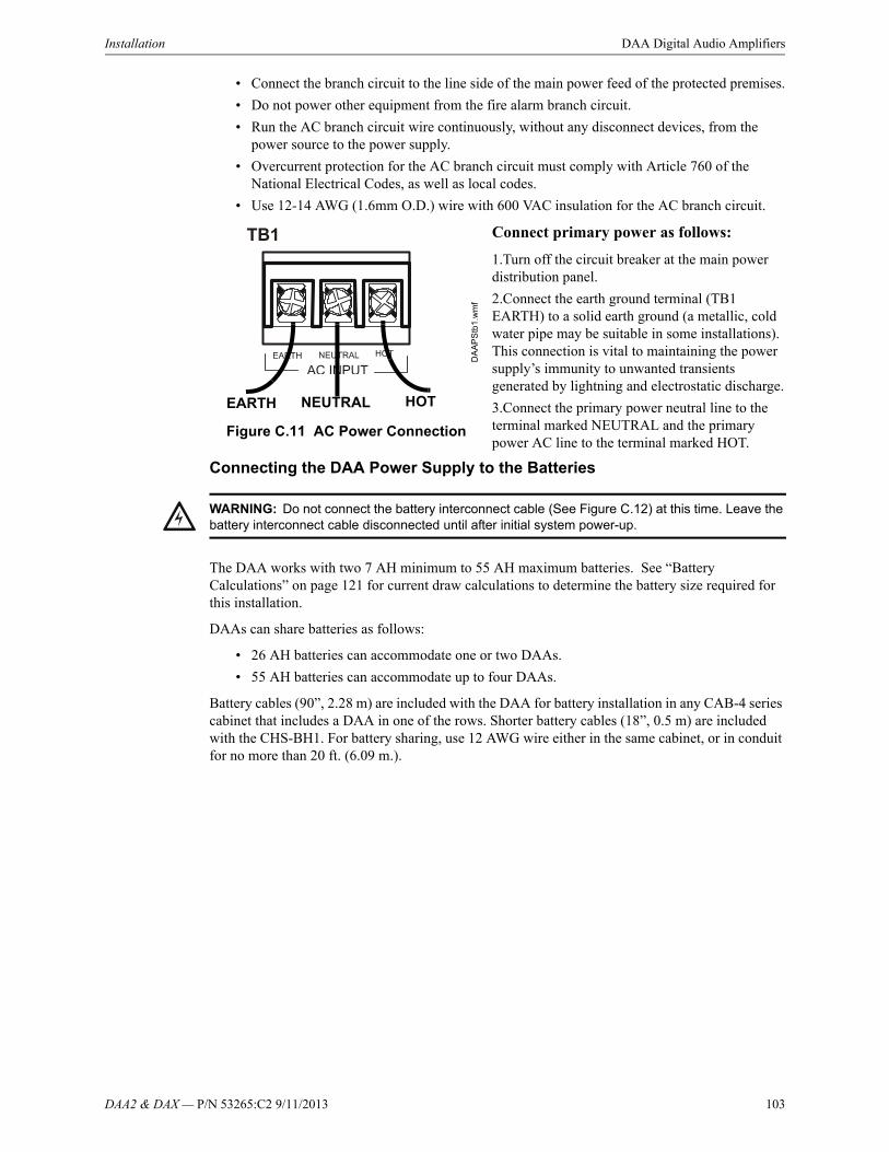
DAA2 & DAX — P/N 53265:C2 9/11/2013 103
Installation DAA Digital Audio Amplifiers
• Connect the branch circuit to the line side of the main power feed of the protected premises.
• Do not power other equipment from the fire alarm branch circuit.
• Run the AC branch circuit wire continuously, without any disconnect devices, from the power source to the power supply.
• Overcurrent protection for the AC branch circuit must comply with Article 760 of the National Electrical Codes, as well as local codes.
• Use 12-14 AWG (1.6mm O.D.) wire with 600 VAC insulation for the AC branch circuit.
Connect primary power as follows:
1.Turn off the circuit breaker at the main power distribution panel.
2.Connect the earth ground terminal (TB1 EARTH) to a solid earth ground (a metallic, cold water pipe may be suitable in some installations). This connection is vital to maintaining the power supply’s immunity to unwanted transients generated by lightning and electrostatic discharge.
3.Connect the primary power neutral line to the terminal marked NEUTRAL and the primary power AC line to the terminal marked HOT.
Connecting the DAA Power Supply to the Batteries
The DAA works with two 7 AH minimum to 55 AH maximum batteries. See “Battery Calculations” on page 121 for current draw calculations to determine the battery size required for this installation.
DAAs can share batteries as follows:
• 26 AH batteries can accommodate one or two DAAs.
• 55 AH batteries can accommodate up to four DAAs.
Battery cables (90”, 2.28 m) are included with the DAA for battery installation in any CAB-4 series cabinet that includes a DAA in one of the rows. Shorter battery cables (18”, 0.5 m) are included with the CHS-BH1. For battery sharing, use 12 AWG wire either in the same cabinet, or in conduit for no more than 20 ft. (6.09 m.).
Figure C.11 AC Power Connection
EARTH NEUTRAL HOT
DA
AP
Stb
1.w
mf
!WARNING: Do not connect the battery interconnect cable (See Figure C.12) at this time. Leave the battery interconnect cable disconnected until after initial system power-up.
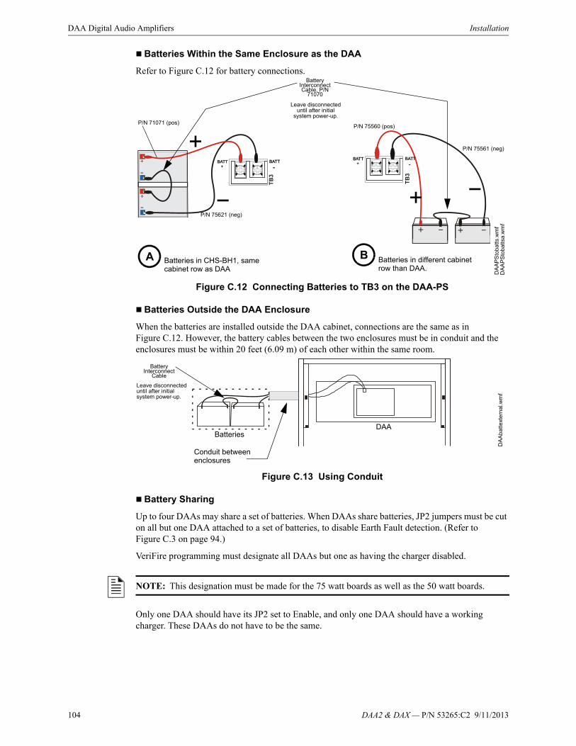
104 DAA2 & DAX — P/N 53265:C2 9/11/2013
DAA Digital Audio Amplifiers Installation
Batteries Within the Same Enclosure as the DAA
Refer to Figure C.12 for battery connections.
Figure C.12 Connecting Batteries to TB3 on the DAA-PS
Batteries Outside the DAA Enclosure
When the batteries are installed outside the DAA cabinet, connections are the same as in Figure C.12. However, the battery cables between the two enclosures must be in conduit and the enclosures must be within 20 feet (6.09 m) of each other within the same room.
Figure C.13 Using Conduit
Battery Sharing
Up to four DAAs may share a set of batteries. When DAAs share batteries, JP2 jumpers must be cut on all but one DAA attached to a set of batteries, to disable Earth Fault detection. (Refer to Figure C.3 on page 94.)
VeriFire programming must designate all DAAs but one as having the charger disabled.
Only one DAA should have its JP2 set to Enable, and only one DAA should have a working charger. These DAAs do not have to be the same.
DA
AP
Sto
ba
tts.w
mf
Battery Interconnect Cable, P/N
71070
Leave disconnected until after initial
system power-up.
Batteries in CHS-BH1, same cabinet row as DAA
Batteries in different cabinet row than DAA.
DA
AP
Sto
bat
tsa
.wm
f
A B
P/N 75560 (pos)
P/N 75561 (neg)
P/N 75621 (neg)
P/N 71071 (pos)
DA
Ab
atte
xte
rnal
.wm
f
DAABatteries
Conduit between enclosures
Battery Interconnect
Cable
Leave disconnected until after initial system power-up.
NOTE: This designation must be made for the 75 watt boards as well as the 50 watt boards.
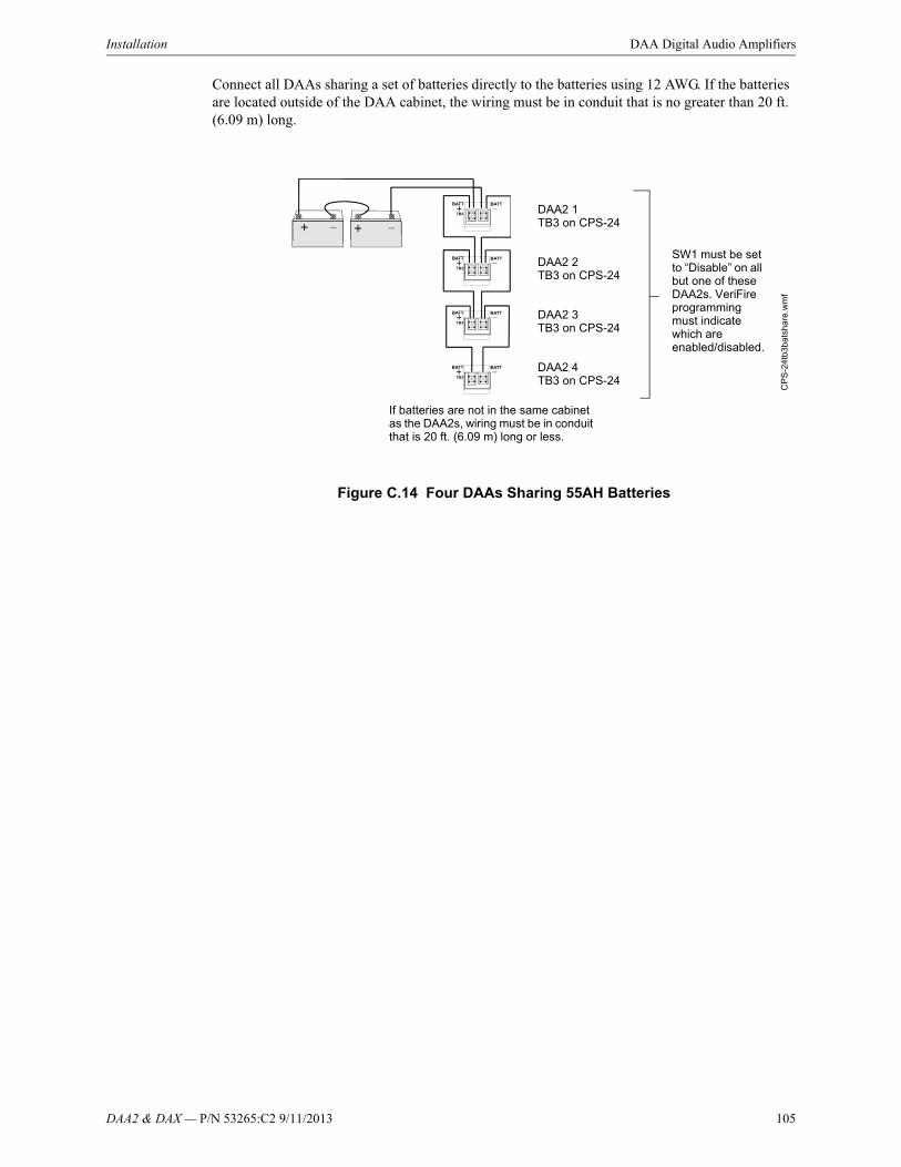
DAA2 & DAX — P/N 53265:C2 9/11/2013 105
Installation DAA Digital Audio Amplifiers
Connect all DAAs sharing a set of batteries directly to the batteries using 12 AWG. If the batteries are located outside of the DAA cabinet, the wiring must be in conduit that is no greater than 20 ft. (6.09 m) long.
Figure C.14 Four DAAs Sharing 55AH Batteries
CP
S-2
4tb
3bat
sha
re.w
mf
If batteries are not in the same cabinet as the DAA2s, wiring must be in conduit that is 20 ft. (6.09 m) long or less.
DAA2 1 TB3 on CPS-24
SW1 must be set to “Disable” on all but one of these DAA2s. VeriFire programming must indicate which are enabled/disabled.
DAA2 2 TB3 on CPS-24
DAA2 3 TB3 on CPS-24
DAA2 4 TB3 on CPS-24
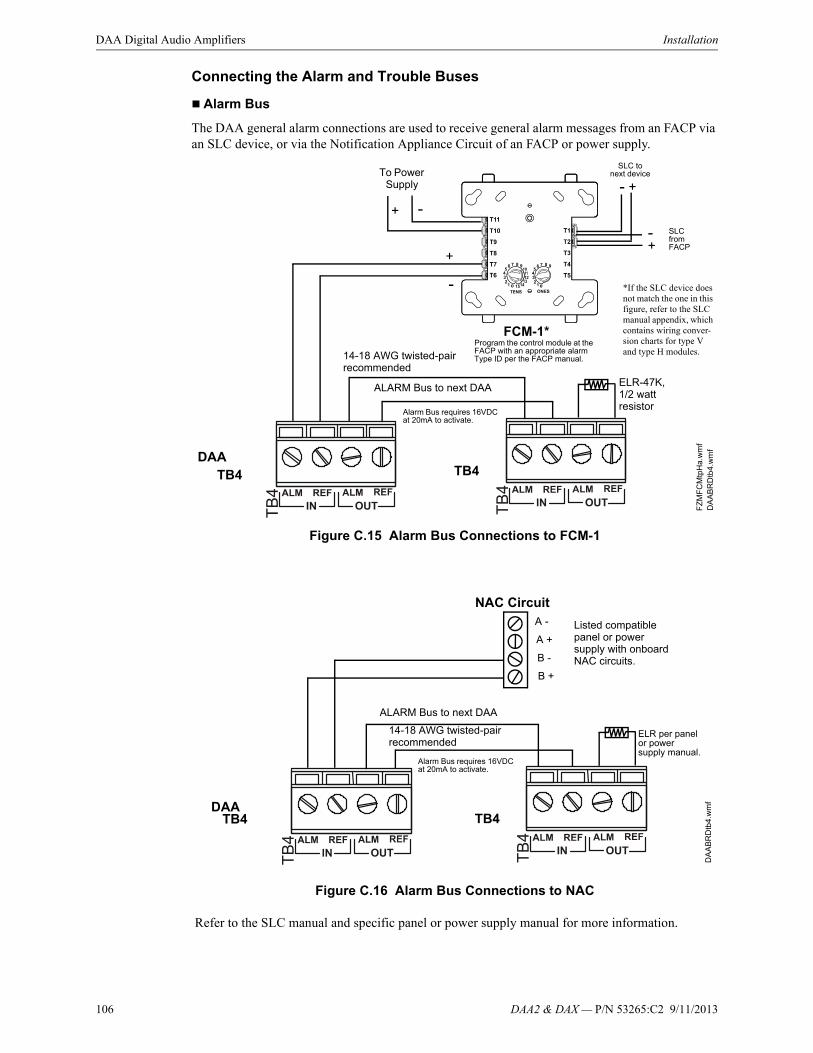
106 DAA2 & DAX — P/N 53265:C2 9/11/2013
DAA Digital Audio Amplifiers Installation
Connecting the Alarm and Trouble Buses
Alarm Bus
The DAA general alarm connections are used to receive general alarm messages from an FACP via an SLC device, or via the Notification Appliance Circuit of an FACP or power supply.
Figure C.15 Alarm Bus Connections to FCM-1
Figure C.16 Alarm Bus Connections to NAC
Refer to the SLC manual and specific panel or power supply manual for more information.
FCM-1*
ALARM Bus to next DAA ELR-47K, 1/2 watt resistor
DAA
FZ
MF
CM
tpH
a.w
mf
DA
AB
RD
tb4.
wm
f
TB4 TB4
14-18 AWG twisted-pair recommended
Program the control module at the FACP with an appropriate alarm Type ID per the FACP manual.
Alarm Bus requires 16VDC at 20mA to activate.
To Power Supply
+- SLC
from FACP
SLC to next device
+-
+ -
+
- *If the SLC device does not match the one in this figure, refer to the SLC manual appendix, which contains wiring conver-sion charts for type V and type H modules.
NAC CircuitA -
A +
B +
B -
ALARM Bus to next DAAD
AA
BR
Dtb
4.w
mf
DAATB4 TB4
ELR per panel or power supply manual.
14-18 AWG twisted-pair recommended
Listed compatible panel or power supply with onboard NAC circuits.
Alarm Bus requires 16VDC at 20mA to activate.
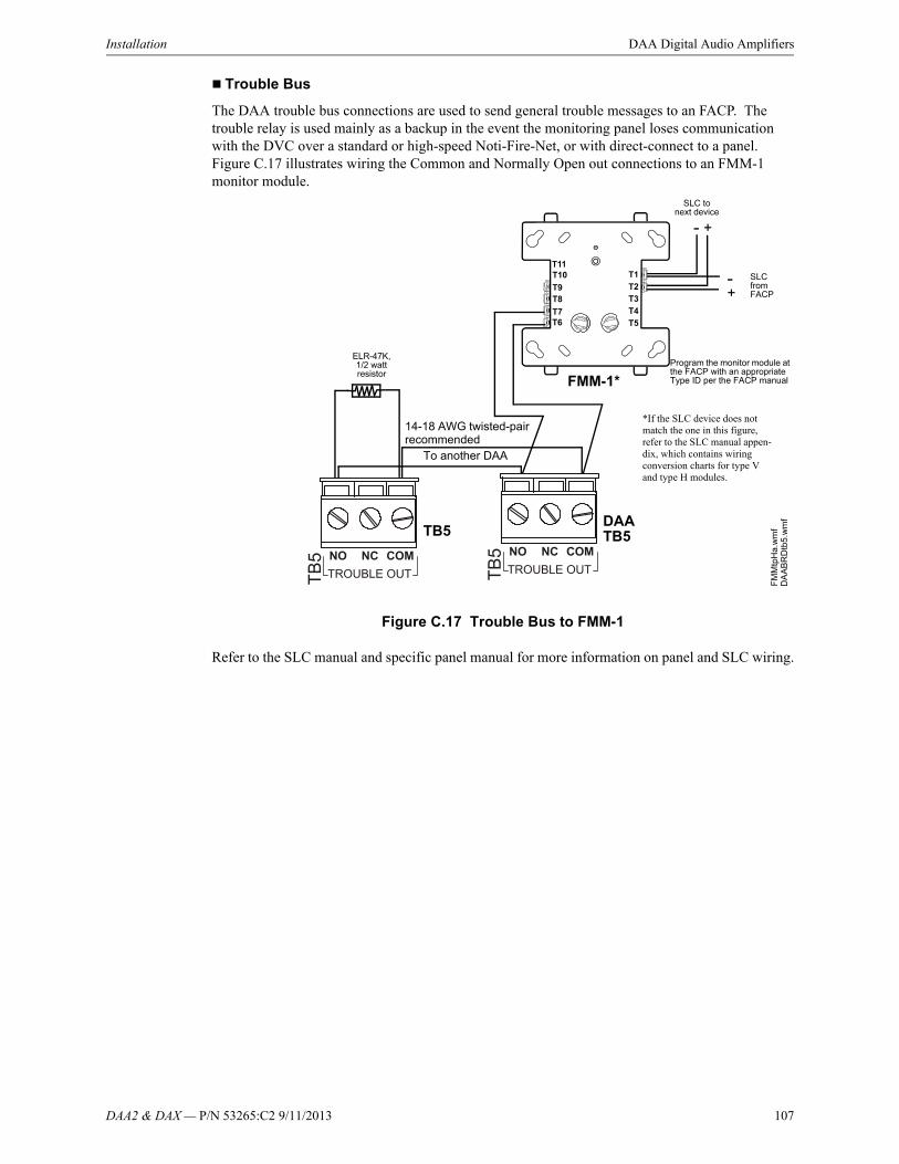
DAA2 & DAX — P/N 53265:C2 9/11/2013 107
Installation DAA Digital Audio Amplifiers
Trouble Bus
The DAA trouble bus connections are used to send general trouble messages to an FACP. The trouble relay is used mainly as a backup in the event the monitoring panel loses communication with the DVC over a standard or high-speed Noti-Fire-Net, or with direct-connect to a panel. Figure C.17 illustrates wiring the Common and Normally Open out connections to an FMM-1 monitor module.
Figure C.17 Trouble Bus to FMM-1
Refer to the SLC manual and specific panel manual for more information on panel and SLC wiring.
DAA
FMM-1*
FM
Mtp
Ha.
wm
f
To another DAA
ELR-47K, 1/2 watt resistor
DA
AB
RD
tb5
.wm
f
TB5
+- SLC
from FACP
+-
TB5
SLC to next device
14-18 AWG twisted-pair recommended
Program the monitor module at the FACP with an appropriate Type ID per the FACP manual
*If the SLC device does not match the one in this figure, refer to the SLC manual appen-dix, which contains wiring conversion charts for type V and type H modules.

108 DAA2 & DAX — P/N 53265:C2 9/11/2013
DAA Digital Audio Amplifiers Installation
Digital Audio Ports A and B on Wire Version Boards
Digital Audio Ports A and B (DAP A and DAP B) allow digital communication with the DVC over the Digital Audio Loop (DAL); amplifier programming from the DVC; control, audio, trouble, address and firefighter telephone data; and live voice paging can be communicated through these ports. They may also act as repeaters, in that what is received at one port is transmitted out the other. Events generated at the DAA will be transmitted out both ports.
Figure C.18 Wire the DAA Digital Audio Loop Connections
Refer to “EFA and EFB (Switches 9 and 10)” on page 119 for information on enabling earth fault detection on the wire DAL.
RXA, RXB, TXA, TXB Fiber Version Board Connections
Fiber ports RXA, RXB, TXA and TXB allow digital communication with DVC fiber boards. When used with other types of DAL devices (e.g. DAA2, DAX) a DS-RFM or DS-SFM fiber option module is required on the DAL device. (Refer to Section 5 on page 75.
Refer to the Wiring Guide, p/n 52916ADD, for acceptable wire types and associated distance between points.
DVC
DAP A+
DAP A-
REF A
DAP B+
DAP B-
REF B
TB
gen3
.wm
f
Optional Class A (Style 7) returnConnections are polarity sensitive.Connections are port sensitive. Always connect Port A to Port B.
DAPA DAPBREF REF
TB
3
TB
2
DAP A+
DAP A-
REF A
DAP B+
DAP B-
REF B
DAA 1 DAA 2 DAA 32
DAP A+
DAP A-
REF A
DAP B+
DAP B-
REF B
NOTE: Digital Audio Ports A and B must be wired in Class B (Style 4) or Class A (Style 7) configuration. Do not wire them in bus configuration.
NOTE: Class B (Style 4) configuration must be installed in accordance with the requirements for survivability from attack by fire in the National Fire Alarm Code, NFPA 72.
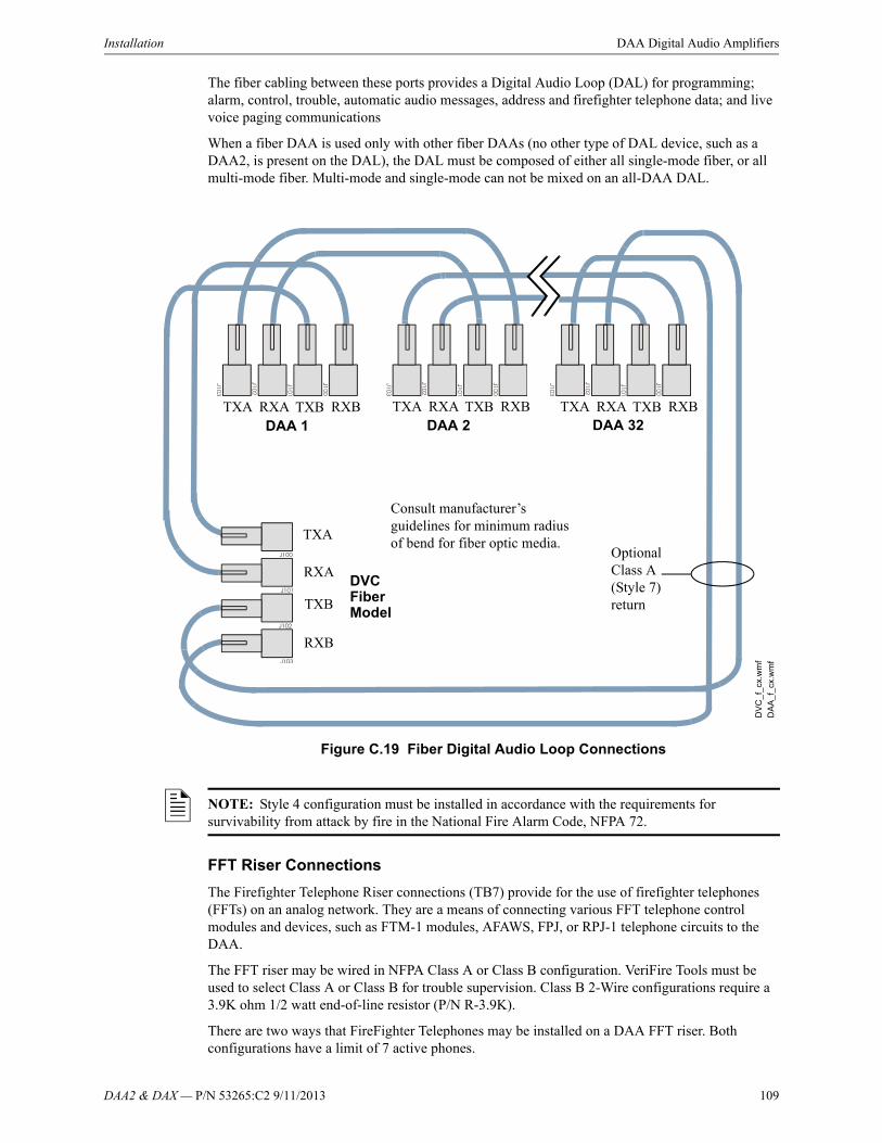
DAA2 & DAX — P/N 53265:C2 9/11/2013 109
Installation DAA Digital Audio Amplifiers
The fiber cabling between these ports provides a Digital Audio Loop (DAL) for programming; alarm, control, trouble, automatic audio messages, address and firefighter telephone data; and live voice paging communications
When a fiber DAA is used only with other fiber DAAs (no other type of DAL device, such as a DAA2, is present on the DAL), the DAL must be composed of either all single-mode fiber, or all multi-mode fiber. Multi-mode and single-mode can not be mixed on an all-DAA DAL.
Figure C.19 Fiber Digital Audio Loop Connections
FFT Riser Connections
The Firefighter Telephone Riser connections (TB7) provide for the use of firefighter telephones (FFTs) on an analog network. They are a means of connecting various FFT telephone control modules and devices, such as FTM-1 modules, AFAWS, FPJ, or RPJ-1 telephone circuits to the DAA.
The FFT riser may be wired in NFPA Class A or Class B configuration. VeriFire Tools must be used to select Class A or Class B for trouble supervision. Class B 2-Wire configurations require a 3.9K ohm 1/2 watt end-of-line resistor (P/N R-3.9K).
There are two ways that FireFighter Telephones may be installed on a DAA FFT riser. Both configurations have a limit of 7 active phones.
TXA
RXA
TXB
RXB
DV
C_
f_cx
.wm
f
DA
A_f
_cx.
wm
f
DVC Fiber Model
TXA RXA TXB RXB TXA RXA TXB RXB
Optional Class A (Style 7) return
TXA RXA TXB RXBDAA 1 DAA 2 DAA 32
Consult manufacturer’s guidelines for minimum radius of bend for fiber optic media.
NOTE: Style 4 configuration must be installed in accordance with the requirements for survivability from attack by fire in the National Fire Alarm Code, NFPA 72.

110 DAA2 & DAX — P/N 53265:C2 9/11/2013
DAA Digital Audio Amplifiers Installation
Programming must reflect whether the riser contains modules or not. Use VeriFire Tools to set these parameters.
1. “Install FTM” selected - Firefighter Telephones must be wired to the output of the FTM modules or an XPIQ. The telephone points will be SLC addresses.
2. “Install FTM” not selected - Firefighter Telephones must be wired directly to the DAA FFT riser. The telephone point will be a DAA phone point. (AxT; where x = the DAA address)
Figure C.20 FFT Riser (Class A Example)
An FHS firefighter handset may be used with the phone jacks in Figure C.20. For a description of the DVC firefighter telephone network operation, refer to the FFT appendix in the DVC Digital Voice Command manual..
Auxiliary Inputs A and B
The DAA provides two analog audio connections. One or the other may be used, not both.
TB
1T
B2
TB
3T
B4
TB
5T
B6
TB
7T
B8
J7J6
J11J12
J13
TB
10
SW
4
JP1JP2
SW
1
EARTH FAULTDETECTION
EARTHFAULT
GEN TBL
DISABLED
ENABLED
P6
P5
P4
P3
P2P1
Low
Le
vel
Bac
kup
INR
em
ote
Ou
tB
CK
GN
DM
US
IC
Rem
ote
In
High LevelBackup IN
High LevelBackup OUT
Low
Le
vel
Ba
ckup O
UT
J9
XPIQ-PS Control Cable
XPIQ-PS Power EXT TRBL IN
SW
3S
W2
PHONE1 AND 2
PHONE3 AND 4
CHGTRBL
Phone 4 TRBL
Phone 3 TRBL
Phone 2 TRBL
Phone1 TRBL
Riser TRBL
TRBL
TRBL
TRBL
TRBL
SPKR1
SPKR2
SPKR3
SPKR4
BATTRBL
A.C.Fail
J1
J2
J10
J4 J5
J8
Phone 1
Phone 2
Phone 3
Phone 4
Spkr1
Spkr2
Spkr3
Spkr4
TB9
2 X 2W
2 X 2W
1 X 4W
1 X 4W
PH
ON
E/N
AC
RIS
ER
XP
IQ-C
A O
ptio
n
SH
LD
- PH
+ S
HL
D - P
H +
+ O
UT
- SH
LD+ O
UT
- SH
LD
+ O
UT
- SH
LD+
OU
T - S
HLD
CO
NT
RO
L/C
OM
M
AU
DIO
IN
AM
PLIF
IER
#4
AM
PLIF
IER
#3
AM
PLIF
IER
#2
AM
PLIF
IER
#1
1 2
1 2
3 4
5 6
S - +
S - +
S - +
S - +
1 2
31 2
31 2
31 2
3
1 2
31 2
31 2
31 2
3
56789
0 1234
NOTIFIER XPIQ-MBPCA REV.
FIREFIGHTER’S
PHONE JACK
FIREFIGHTER’S
PHONE JACK
SHLD SHLD
RISER OUT RISER RTN
Telephone Control Module
XPIQ
FPJ or RPJ-1 Firefighter
Phone Jack
DV
CF
FT
rise
r.w
mf
DAA
AFAWS Fire Alarm Warden
Station
TB7
Max wiring resistance (including individual telephone zone to last
handset) permitted is 50 ohms. 10,000 ft. (3048 m) max. wiring distance at 14
AWG to last handset.
14-18 AWG twisted-pair recommended
Telephone Control Module
Telephone Control Module
FPJ or RPJ-1 Firefighter
Phone Jack
NOTE: If an FFT riser is not programmed for modules, telephone modules, as well as the XPIQ, are not options.
NOTE: Digital audio software Version 2.0 and above does not support FFT risers on DVC or DAA PCA boards. Refer to Figure C.2 on page 93 for how to determine DAA board type. Refer to the DVC Digital Voice Command manual for how to distinguish PCA from PCB board types. Check VeriFire or an appropriate network display to determine the software version.
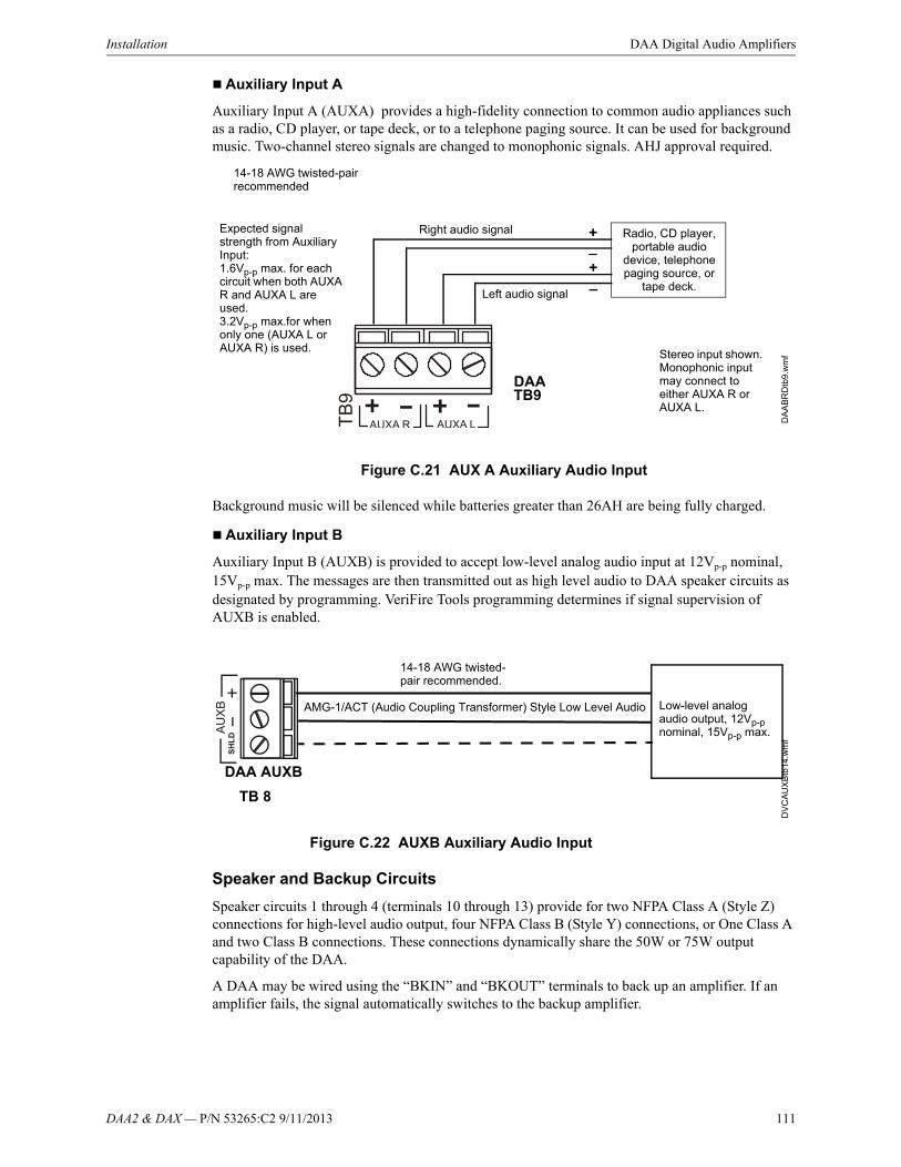
DAA2 & DAX — P/N 53265:C2 9/11/2013 111
Installation DAA Digital Audio Amplifiers
Auxiliary Input A
Auxiliary Input A (AUXA) provides a high-fidelity connection to common audio appliances such as a radio, CD player, or tape deck, or to a telephone paging source. It can be used for background music. Two-channel stereo signals are changed to monophonic signals. AHJ approval required.
Figure C.21 AUX A Auxiliary Audio Input
Background music will be silenced while batteries greater than 26AH are being fully charged.
Auxiliary Input B
Auxiliary Input B (AUXB) is provided to accept low-level analog audio input at 12Vp-p nominal, 15Vp-p max. The messages are then transmitted out as high level audio to DAA speaker circuits as designated by programming. VeriFire Tools programming determines if signal supervision of AUXB is enabled.
Figure C.22 AUXB Auxiliary Audio Input
Speaker and Backup Circuits
Speaker circuits 1 through 4 (terminals 10 through 13) provide for two NFPA Class A (Style Z) connections for high-level audio output, four NFPA Class B (Style Y) connections, or One Class A and two Class B connections. These connections dynamically share the 50W or 75W output capability of the DAA.
A DAA may be wired using the “BKIN” and “BKOUT” terminals to back up an amplifier. If an amplifier fails, the signal automatically switches to the backup amplifier.
Radio, CD player, portable audio
device, telephone paging source, or
tape deck.
_+
_+
Left audio signal
Right audio signal
DAA
DA
AB
RD
tb9
.wm
f
TB9
Stereo input shown. Monophonic input may connect to either AUXA R or AUXA L.
14-18 AWG twisted-pair recommended
Expected signal strength from Auxiliary Input:1.6Vp-p max. for each circuit when both AUXA R and AUXA L are used.3.2Vp-p max.for when only one (AUXA L or AUXA R) is used.
DAA AUXB
AMG-1/ACT (Audio Coupling Transformer) Style Low Level Audio
TB 8D
VC
AU
XB
tb1
4.w
mf
14-18 AWG twisted-pair recommended.
Low-level analog audio output, 12Vp-p nominal, 15Vp-p max.
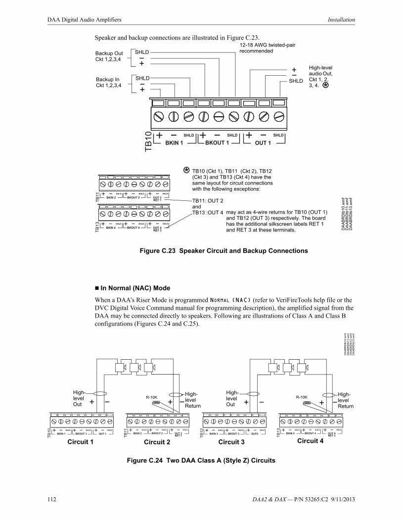
112 DAA2 & DAX — P/N 53265:C2 9/11/2013
DAA Digital Audio Amplifiers Installation
Speaker and backup connections are illustrated in Figure C.23.
In Normal (NAC) Mode
When a DAA’s Riser Mode is programmed NORMAL (NAC) (refer to VeriFireTools help file or the DVC Digital Voice Command manual for programming description), the amplified signal from the DAA may be connected directly to speakers. Following are illustrations of Class A and Class B configurations (Figures C.24 and C.25).
Figure C.24 Two DAA Class A (Style Z) Circuits
TB10 (Ckt 1), TB11 (Ckt 2), TB12 (Ckt 3) and TB13 (Ckt 4) have the same layout for circuit connections with the following exceptions:
TB11: OUT 2andTB13 :OUT 4
DA
AB
RD
tb10
.wm
f
Backup InCkt 1,2,3,4
SHLD
Backup OutCkt 1,2,3,4
SHLD
High-level audio Out, Ckt 1, 2, 3, 4.
SHLD
may act as 4-wire returns for TB10 (OUT 1) and TB12 (OUT 3) respectively. The board has the additional silkscreen labels RET 1 and RET 3 at these terminals. D
AA
BR
Dtb
11.w
mf
DA
AB
RD
tb13
.wm
f
*
*
12-18 AWG twisted-pair recommended
Figure C.23 Speaker Circuit and Backup Connections
Circuit 1 Circuit 2 Circuit 3 Circuit 4
High- level Return
High- level Out
R-10KHigh- level Return
High- level Out
R-10K
DA
AB
RD
tb1
0.w
mf
DA
AB
RD
tb1
1.w
mf
DA
AB
RD
tb1
3.w
mf
DA
AB
RD
tb1
2.w
mf

DAA2 & DAX — P/N 53265:C2 9/11/2013 113
Installation DAA Digital Audio Amplifiers
In Riser Mode to Additional Amplifiers
When a DAA’s Riser Mode is programmed RISER MODE TO ADDITIONAL AMPLIFIERS (refer to VeriFireTools help file or the DVC Digital Voice Command manual for programming description), the amplified signal from the DAA may be connected to an audio coupling transformer (ACT-25 for 25V amplifiers, ACT-70 for 70V amplifiers) to drive additional AA-Series amplifiers. This mode provides a 200 Hz aupervisory tone required by analog amplifiers.
Figure C.26 DAA Riser Mode to Additional Amplifiers
Refer to the ACT-25 or ACT-70 installation document for more information.
In Riser Mode to Control Modules
When a DAA’s Riser Mode is programmed RISER MODE TO CONTROL MODULES (refer to VeriFireTools help file or the DVC Digital Voice Command manual for programming description), the amplified signal from the DAA may be routed to multiple speaker circuits using SLC control modules.
High- level Return
High- level Out
R-10K
Circuit 1 Circuit 2 Circuit 3 Circuit 4
20k ohm end-of-line resistor, p/n ELR-20K
20k ohm end-of-line resistor, p/n ELR-20K
Figure C.25 One DAA Class A (Style Z) Circuit, Two Class B (Style Y) Circuits
AA-100/AA-100Eor
AA-120/AA-120EAA-30/AA-30E
Audio Coupling Transformer
DAA
Low-level Audio Low-level Audio
High-level AudioHigh-level AudioTo other audio coupling transformers or 20k ELR (Class B)
Optional 4-wire return from last audio coupling transformer
TB1
P1 P1
TB1
TB10
TB11
10k ELR (Class A)
DA
A_A
CT
HI_
riser
mod
e.w
mf
AudioCoupling
Transformer
Up to 7 low-level
inputs
Up to 7 low-level
inputs

114 DAA2 & DAX — P/N 53265:C2 9/11/2013
DAA Digital Audio Amplifiers Installation
Only one Class A or Class B DAA speaker circuit may be installed when operating in this mode.
Do not use background music in this mode. The DAA will provide speaker circuit supervision only when idle.
In Riser Mode to RSM/AIM Series Canadian Room Isolator Modules
When a DAA’s Riser Mode is programmed RISER MODE TO RSM/AIM SERIES MODULES (refer to VeriFireTools help file or the DVC Digital Voice Command manual for programming description), the amplified signal from the DAA is routed to RSM-1A or AIM-1A room isolator modules.
Only one Class A or Class B DAA speaker circuit may be installed when operating in this mode.
AIM-1A - Provides isolation to a separate circuit on an audio riser. A short circuit on an AIM-1A speaker circuit will not disable other speaker circuits on the riser.
RSM-1A - Works same as the AIM-1A, with the exception that there is a silence button for in-suite operation. The silence button will silence the audible signal to the module’s circuit for ten minutes during alarm. Resounding will occur automatically after ten minutes. To override the ten minute silence, CBE programming must be done at the FACP so that it interrupts the module’s 24VDC power for two seconds.
NFS2-3030 example:
Give the isolator module’s 24VDC source a common ground with the DAA2 amplifier. Power the isolator module through a relay module that has Special Zone 14 in its CBE list. Special Zone 14 will activate for ten seconds when a reset is initiated at the panel.This period is used to disable the 24VDC for those 10 seconds to clear a local silence.
DAATB10
DA
A_
AC
TH
I_ri
serm
ode
.wm
f
20k ELR (Class B)
SLC Control Module
SLC Control Module
SLC Control Module
Figure C.27 DAA Riser Mode to Control Modules

DAA2 & DAX — P/N 53265:C2 9/11/2013 115
Installation DAA Digital Audio Amplifiers
Remove jumpers for speaker applications. (Refer to Figure C.28.)
Figure C.28 Jumper Settings for Speaker Applications
In Riser Mode to CIM/CSM Series Canadian Room Isolator Modules
When a DAA’s Riser Mode is programmed RISER MODE TO CIM/CSM SERIES MODULES (Refer to VeriFireTools help file or the DVC Digital Voice Command manual for programming description), the amplified signal from the DAA is routed to a CIM-2A module, which feeds the signal to one or two CSM-1A modules.
A pre-announce tone of 800 Hz will clear a local silence.
Only one Class A or Class B DAA speaker circuit may be installed when operating in this mode.
AIM-1ARemove jumpers 1 & 2 for speaker applications
RSM-1ARemove jumpers 1 & 2 for speaker applications
Jumper 3
Voi
ce_A
IM-1
back
.wm
fV
oic
e_R
SM
-1ba
ck.w
mf
AIM- RSM-
RSM-1A/AIM-1A
RSM-1A/AIM-1A
External 24V UL/ULC-listed power supply
DAA TB10
DAA and power supply must share a common
ground.
DAA and power supply must share a common
ground.
External 24V UL/ULC-listed power supply
Optional 4-wire return.
Supervised Speakers Unsupervised Speakers
Figure C.29 DAA Riser Mode to RSM-1A/AIM-1A Modules
24V to next device
To next module, EOL resistor, orClass A return.
To next module, EOL resistor, or Class A return.
24V to next device
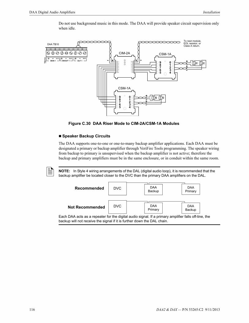
116 DAA2 & DAX — P/N 53265:C2 9/11/2013
DAA Digital Audio Amplifiers Installation
Do not use background music in this mode. The DAA will provide speaker circuit supervision only when idle.
Speaker Backup Circuits
The DAA supports one-to-one or one-to-many backup amplifier applications. Each DAA must be designated a primary or backup amplifier through VeriFire Tools programming. The speaker wiring from backup to primary is unsupervised when the backup amplifier is not active; therefore the backup and primary amplifiers must be in the same enclosure, or in conduit within the same room.
Figure C.30 DAA Riser Mode to CIM-2A/CSM-1A Modules
CIM-2A
DAA TB10To next module, EOL resistor, orClass A return.
CSM-1A
CSM-1A
NOTE: In Style 4 wiring arrangements of the DAL (digital audio loop), it is recommended that the backup amplifier be located closer to the DVC than the primary DAA amplifiers on the DAL.
Each DAA acts as a repeater for the digital audio signal. If a primary amplifier falls off-line, the backup will not receive the signal if it is further down the DAL chain.
DVC
DVC
DAA Backup
DAA Backup
DAA Primary
DAA Primary
Recommended
Not Recommended

DAA2 & DAX — P/N 53265:C2 9/11/2013 117
Installation DAA Digital Audio Amplifiers
• One-to-One Backup
Figure C.31 illustrates output sources 1, 2, 3 and 4 on the primary amplifier backed up by the backup amplifier. Should the primary amplifier fail, all its messages will still be played as programmed.
Figure C.31 One-to-one, All Sources Backed Up
• One-to-Many Backup
One amplifier may be used to back up as many as 31 primary DAA amplifiers. All primary amplifiers backed by the same backup amplifier must each be wired in the same style or combination of styles; for example, all wired Class A (Style Z), or all wired Class B (Style Y), or all wired with one Class A and two Class B circuits.
VeriFire Tools Programming
Backup DAA Address 1
Primary DAA Address 2
DAP A+
DAP A-
REF A
DVC
TB2
TB3
DAP B+
DAP B-
REF B
Primary DAA Backup DAA
Digital Signal from DVC
20k ohm end-of-line resistor,
p/n ELR-20K
ELR-20k
ELR-20k
ELR-20k
Optional Class A Return

118 DAA2 & DAX — P/N 53265:C2 9/11/2013
DAA Digital Audio Amplifiers Installation
A backup amplifier can support one failed primary amplifier at a time. Should another primary amplifier also fail, the backup amplifier may also fail, generating an AMPLIFIER LIMIT trouble until the load is reduced or reset.
Figure C.32 One-to-Many Backup
UL Power-limited (Class 2) Wiring Requirements
Power-limited and non-power-limited circuit wiring must remain separated in the cabinet. All power-limited circuit wiring must remain at least 0.25 inches (6.35 mm) from any non-power-limited circuit wiring. All power-limited and non-power-limited circuit wiring must enter and exit the cabinet through different knockouts and/or conduits.
Figure C.33 Typical Backbox Wiring
Primary DAA 1 Primary DAA 2 Primary DAA 32
DA
AB
RD
tb1
0.w
mf
From “Out” terminals on backup amplifier
ToSpeakers
ToSpeakers
ToSpeakers
Power-limited (Class 2) circuits
Non-power-limited circuits
DA
AU
Lwir
ing.
wm
f

DAA2 & DAX — P/N 53265:C2 9/11/2013 119
Configuration DAA Digital Audio Amplifiers
C.3 Configuration
C.3.1 Setting the Configuration Switches
EFA and EFB (Switches 9 and 10)
The wire versions of the DAA boards have two earth fault detection switches for use with Digital Audio Ports (DAPs) A and B. The switches arrive from the factory disabled, and may require resetting if earth fault detection is desired.
Each DAP on a DAA or DVC is electrically isolated from the other DAP and all other circuitry on the DAA or DVC.
A DAP with its associated earth fault switch enabled must be connected to a DAP with its associated earth fault switch disabled for detection to occur. Otherwise, either
• no detection will occur (when two connected DAPs have their associated switches disabled), or
• an earth fault will be generated (when two connected DAPs have their associated switches enabled).
Refer to Figure C.35.
Figure C.35 Earth Fault Switch Settings for a Wire Digital Audio Loop (DAL)
DAAs may be used on a DAL with other devices that have different earth fault detection (e.g., DAA2, DAX). Refer to the DAL Earth Fault Detection appendix in the DVC Digital Voice Command manual for examples of how to mix devices with different earth fault detection.
4WIRE (Switch 11)
The FFT riser may be wired in a Class A four-wire or a Class B two-wire configuration. For Class A installations, enable the switch. For Class B, disable the switch.
VeriFire Tools programming must be set the same as this switch.
Figure C.34 EFA/EFB Enable/Disable
SW9 and SW10 in DISABLE position
To enable, push the switch towards EN.
DIS
EN
EF
A DISEF
B
EN
SW
ge
n.w
mf
SW
ge
na.w
mf
DVC
EFA ENDAPA
DAPB
DAA DAA
DAPA DAPB DAPA DAPB
DAA
DAPA DAPB
Optional Class A (Style 7) return
For specific DAP wiring instructions refer to “Digital Audio Ports A and B on Wire Version Boards” on page 108.
Twisted-pair wire.
EFB DIS
EF
B D
ISE
FA
EN
EF
B D
ISE
FA
EN
EF
B D
ISE
FA
EN
Figure C.36 4WIRE Enable/Disable
SW11 in enabled position.
To disable, push the switch towards DIS.
DIS
EN
4W
IRE

120 DAA2 & DAX — P/N 53265:C2 9/11/2013
DAA Digital Audio Amplifiers Programming
Address Switches
A maximum of 32 DAAs may be connected to one DVC. Each DAA (or other DAL device) must have its own address so the events it generates can be distinguished from those of other DAL devices, for unique routing of messages and sounds, and for speaker circuit control. Address switches SW2 (tens) and SW3 (ones) are used to address the DAA. Refer to Figure C.37 for an illustration of addess settings and to Figure C.3 on page 94 for the location of the switches.
Addresses one (1) through 32 may be used for digital communication. Address 00 and addresses above 32 will generate a DAA trouble.
The default address setting for the DAA as it arrives from the factory is 00.
Volume Control
A rotary switch (SW7) is supplied to adjust the volume for local background music from the AUXA input.The default volume setting for the DAA as it arrives from the factory is 0 (Low). Turning the arrow counter-clockwise to increase the volume.Refer to Figure C.3 on page 94 for the location of this control.
C.4 ProgrammingThe DAA is programmed through VeriFire Tools. Refer to the programming section in the DVC Digital Voice Command manual as well as the VeriFire Tools CD and Help file for information on how to create, prioritize and download audio messages, create system equations for message distribution, and set system parameters.
C.5 Operation
C.5.1 Pushbutton Controls
Table C.5 summarizes the functions of each pushbutton control.
Table C.5 Pushbutton Controls
Figure C.37 DAA Address Switches
DAA Address set to 14
The SW2 arrow points to one (1). Tens switch set to one (1).
The SW3 arrow points to four (4). Ones switch set to four (4).
DA
A A
ddrs
wtc
hs.w
mf
Figure C.38 DAA Volume Control
DA
A v
olct
lSW
7.w
mf
Pushbutton Function When to use
F1 Silences speaker circuits 1 through 4. This pushbutton is enabled by the DAA when there is a communication loss with the DVC.
To turn off speaker outputs on speaker circuits 1 through 4.
F2 Clears local signal silences and reinitializes the amplifier if it turned off due to overcurrent protection.
After causes of DAA trouble messages have been cleared.

DAA2 & DAX — P/N 53265:C2 9/11/2013 121
Battery Calculations DAA Digital Audio Amplifiers
C.5.2 Volume Control
The DAA provides a volume control for background music from auxiliary port A or B (See “Volume Control” on page 120). The volume of other audio messages is determined through the VeriFire Tools Read Status Service Form and FACP/network annunciator programming.
C.5.3 Read/Alter Status
An NCA-2, NFS2-3030 and network workstation, as well as a computer running VeriFire Tools and connected to the NUP port of the DVC, will be able to read the status of a DAA and its speaker circuits. Refer to the appropriate panel manual or the VeriFire Tools Read Status Service Form.
A DAA speaker circuit may be disabled though NCA-2 and NFS2-3030 Alter Status panel programming and ACS programming.
C.5.4 FFT Communication
Refer to the FFT appendix in the DVC Digital Voice Command manual for information on Firefighter Telephone system communication.
C.5.5 Trouble Messages
Refer to the System Troubles appendix in the DVC Digital Voice Command manual for a description of system troubles.
C.6 Battery Calculations
Table C.6 Current Draw Calculations Per DAA
Description Column AAmps in Standby
Column BAmps in Alarm
QTY X current draw = Total QTY X current draw = Total
DAA* 1 X [ 0.350A ] = 0.350A 1 X [ 0.600A ] = 0.600A
Speakers:
1/4 watt [ ] X [ 0.016A ] =
1/2 watt [ ] X [ 0.032A ] =
3/4 watt [ ] X [ 0.0485A ] =
1 watt [ ] X [ 0.064A ] =
2 watt [ ] X [ 0.132A ] =
Other _______ [ ] X[ ] = [ ] X [ ] =
Total Column A _______ Total Column B _______
* Includes FFT Riser Draw
NOTE: Battery Sharing - When batteries are shared by two or more DAAs, Table C.6 must be completed for each DAA. The totals for Columns A and Columns B must be summed and entered into Table C.7 where indicated.
Load Totals Multiplied By Time Equals Secondary Amp Hour Totals

122 DAA2 & DAX — P/N 53265:C2 9/11/2013
DAA Digital Audio Amplifiers Battery Calculations
Table C.7 Secondary Power Standby and Fire Alarm Load
Table C.8 Battery Size Requirements
Enter total from Column A in Table C.6. (Standby Load)
[ ] XRequired Secondary Non-
fire Alarm Standby Time (24 or 60 hours)
[ ] = [ ]Non-fire Alarm
Secondary Standby Amp Hours
Enter total from Column B in Table C.6. (Alarm Load)
[ ] XRequired Fire Alarm Time
in Decimal Form*[ ] = [ ]
Secondary Fire Alarm Amp Hour Requirement
Sum column for Total Secondary Ampere Hours (AH) Calculated =
Multiply by the derating factor X 1.2 = [ ] Total Secondary Ampere Hours Required
*Following are decimal conversions for standard numbers of minutes:
5 minutes10 minutes15 minutes30 minutes60 minutes
0.0840.1670.2500.501.0
Standby operating times:• NFPA 72 Local, Proprietary, Auxiliary, Remote Station, and Central Station systems require 24 hours of standby power followed
by 5 minutes in alarm.• Some jurisdictions require 60 hours of standby power followed by 5 minutes in alarm for Auxiliary and Remote Station systems,
based on previous NFPA 72 requirements.• 24 hours of standby/supervisory condition followed by 2 hours of alarm.
Battery Size Voltage Rating Required Number Model Number
7 AH 12 volts Two BAT-1270
12 AH 12 volts Two BAT-12120
26 AH 12 volts Two BAT-12260
55 AH 12 volts Two BAT-12550

DAA2 & DAX — P/N 53265:C2 9/11/2013 123
Notes
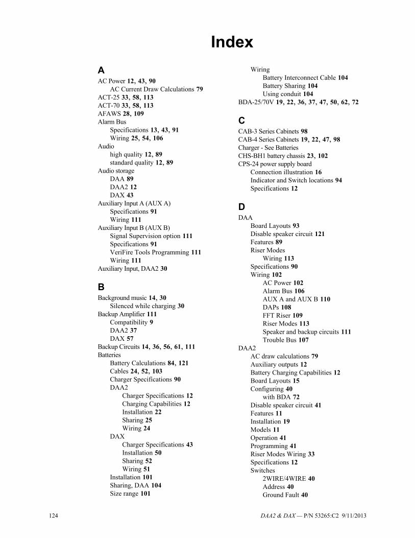
124 DAA2 & DAX — P/N 53265:C2 9/11/2013
Index
AAC Power 12, 43, 90
AC Current Draw Calculations 79ACT-25 33, 58, 113ACT-70 33, 58, 113AFAWS 28, 109Alarm Bus
Specifications 13, 43, 91Wiring 25, 54, 106
Audiohigh quality 12, 89standard quality 12, 89
Audio storageDAA 89DAA2 12DAX 43
Auxiliary Input A (AUX A)Specifications 91Wiring 111
Auxiliary Input B (AUX B)Signal Supervision option 111Specifications 91VeriFire Tools Programming 111Wiring 111
Auxiliary Input, DAA2 30
BBackground music 14, 30
Silenced while charging 30Backup Amplifier 111
Compatibility 9DAA2 37DAX 57
Backup Circuits 14, 36, 56, 61, 111Batteries
Battery Calculations 84, 121Cables 24, 52, 103Charger Specifications 90DAA2
Charger Specifications 12Charging Capabilities 12Installation 22Sharing 25Wiring 24
DAXCharger Specifications 43Installation 50Sharing 52Wiring 51
Installation 101Sharing, DAA 104Size range 101
WiringBattery Interconnect Cable 104Battery Sharing 104Using conduit 104
BDA-25/70V 19, 22, 36, 37, 47, 50, 62, 72
CCAB-3 Series Cabinets 98CAB-4 Series Cabinets 19, 22, 47, 98Charger - See BatteriesCHS-BH1 battery chassis 23, 102CPS-24 power supply board
Connection illustration 16Indicator and Switch locations 94Specifications 12
DDAA
Board Layouts 93Disable speaker circuit 121Features 89Riser Modes
Wiring 113Specifications 90Wiring 102
AC Power 102Alarm Bus 106AUX A and AUX B 110DAPs 108FFT Riser 109Riser Modes 113Speaker and backup circuits 111Trouble Bus 107
DAA2AC draw calculations 79Auxiliary outputs 12Battery Charging Capabilities 12Board Layouts 15Configuring 40
with BDA 72Disable speaker circuit 41Features 11Installation 19Models 11Operation 41Programming 41Riser Modes Wiring 33Specifications 12Switches
2WIRE/4WIRE 40Address 40Ground Fault 40

DAA2 & DAX — P/N 53265:C2 9/11/2013 125
Index E–P
Primary Amp 41SIG SIL 41
Troubles - see Troubles appendixVolume Control 41Wiring 23
AC Power 23Alarm Bus 25AUX A 30Batteries 24DAPs 27FFT Riser 28Riser Modes 33RMI 30Speaker circuits 30
DAAPCA boards 100DAAPCB boards 100DAA-PS power supply board
Connection Ilustration 93Specifications 90
DAL 27, 55, 108, 109Block Diagram 89Earth Fault Detection 119
DAPsSpecifications 13, 43, 90Style 4, Style 7 27, 55, 108Wiring 27, 55, 108
DAXAC draw calculations 81Battery Charger 43Board Layouts 45Configuring 65Features 42Installation 47Models 42Operation 65Riser Modes Wiring 58Specifications 43Wiring 51
AC Power 51Alarm Bus 54Batteries 51DAPs 55Riser Modes 58Speaker and backup circuits 56
DCL, see SLC 35, 115Digital Audio Ports, see DAPsDisable DAA speaker circuit 41, 121DP-1B Dress Panel 22, 50, 100DS-RFM 76
EEarth fault
DAA2 19Earth fault switch
DAX-35 65ELR-20k 14, 32, 57, 92, 113, 117
EQ Series backboxes and doors 19, 47EQCAB backboxes and doors 98EQCAB-X4 cabinets and part numbers 101
FFCM-1 26, 54, 106FFT Riser
Specifications 13, 91Wiring 28, 109
Fiber option modules 75Disabling corresponding wire connections
13, 43FMM-1 107FPJ 29FPJ-1 110FTM-1 28, 109
GGround fault
DAA2 40Group Configurations, DAA2 with BDA 72
HHigh quality audio storage 12, 89
IInstallation 19, 47
LLED Indicator
Descriptions 96DAA2 18DAX 46
Locations 94, 96DAA2 17DAX 46
NNCA-2 41, 66, 121NCM-W/F 50, 100NFS2-3030 41, 66, 121
OOperation 41, 65
PPower Supply Board specs 12Power-limited Requirements 39, 64, 118Programming 41, 65, 120

126 DAA2 & DAX — P/N 53265:C2 9/11/2013
R–W Index
RR-10k 14, 32, 57, 92, 112, 113R-3.9k 13, 28, 91, 109Read Status 41, 66Read status 121Riser Modes
DAA2Normal 32to Additional Amplifiers 33to CIM/CSM Series 35to Control Modules 33to RSM/AIM Series 34
DAXNormal 57to Additional Amplifiers 58to CIM/CSM Series 60to Control Modules 58to RSM/AIM Series 59
RM-1 Series microphone 30RMI Remote Microphone Interface
Specification 13Wiring 30
Room Isolator Modules 34, 60, 114RPJ-1 29
SSIG SIL Pushbutton Switch 41Speaker Circuits
Backup Wiring 111, 116DAA2
Backup Wiring 36Specifications 14Wiring 30
DAXBackup Wiring 61Specifications 44Wiring 56
Specifications 91Wiring 111
SpecificationsDAA 90DAA2 13DAA-PS power supply board 90Power supply board on DAA2 12
Standard quality audio storage 12, 89Switches
DAA2Description 19Location 17Setting 2/4 Wire 40Setting Address 40
DAXDescription 47Earth Fault 65Location 46Setting Address 65
Description 98Location 94, 96Setting
4WIRE 119Addresses 120EFA and EFB 119Volume Control 120
TTelephone Control Modules 28Trouble Bus
Specifications 91Wiring 107
Trouble messages 41
WWARNING
Batteries contain sulfuric acid.... 22, 50,101
Do not connect battery interconnect cableuntil after initial system power-up. 24, 51, 103
High Voltages Present.... 23, 51, 102Protect threading, electronics, eyes while
cutting stud. 99Wear a static discharge wrist strap... 20,
48, 98Wiring
Alarm Bus 54, 106Auxiliary Input A 30Auxiliary Inputs A and B 110DAA power supply to AC Power 102DAA2 power supply to AC Power 23DAX to AC Power 51Digital Audio Ports A and B 27, 55, 108FFT Riser 28, 109Speaker and Backup Circuits 56, 111Speaker Circuits 30Trouble Bus 107
Manufacturer Warranties and Limitation of LiabilityManufacturer Warranties. Subject to the limitations set forth herein,Manufacturer warrants that the Products manufactured by it in itsNorthford, Connecticut facility and sold by it to its authorizedDistributors shall be free, under normal use and service, from defectsin material and workmanship for a period of thirty six months (36)months from the date of manufacture (effective Jan. 1, 2009). TheProducts manufactured and sold by Manufacturer are date stamped atthe time of production. Manufacturer does not warrant Products thatare not manufactured by it in its Northford, Connecticut facility butassigns to its Distributor, to the extent possible, any warranty offeredby the manufacturer of such product. This warranty shall be void if aProduct is altered, serviced or repaired by anyone other thanManufacturer or its authorized Distributors. This warranty shall alsobe void if there is a failure to maintain the Products and the systems inwhich they operate in proper working conditions.
MANUFACTURER MAKES NO FURTHER WARRANTIES, ANDDISCLAIMS ANY AND ALL OTHER WARRANTIES, EITHEREXPRESSED OR IMPLIED, WITH RESPECT TO THE PRODUCTS,TRADEMARKS, PROGRAMS AND SERVICES RENDERED BYMANUFACTURER INCLUDING WITHOUT LIMITATION,INFRINGEMENT, TITLE, MERCHANTABILITY, OR FITNESS FORANY PARTICULAR PURPOSE. MANUFACTURER SHALL NOT BELIABLE FOR ANY PERSONAL INJURY OR DEATH WHICH MAYARISE IN THE COURSE OF, OR AS A RESULT OF, PERSONAL,COMMERCIAL OR INDUSTRIAL USES OF ITS PRODUCTS.
This document constitutes the only warranty made by Manufacturerwith respect to its products and replaces all previous warranties and isthe only warranty made by Manufacturer. No increase or alteration,written or verbal, of the obligation of this warranty is authorized.Manufacturer does not represent that its products will prevent any lossby fire or otherwise.
Warranty Claims. Manufacturer shall replace or repair, atManufacturer's discretion, each part returned by its authorizedDistributor and acknowledged by Manufacturer to be defective,provided that such part shall have been returned to Manufacturer withall charges prepaid and the authorized Distributor has completedManufacturer's Return Material Authorization form. The replacementpart shall come from Manufacturer's stock and may be new orrefurbished. THE FOREGOING IS DISTRIBUTOR'S SOLE ANDEXCLUSIVE REMEDY IN THE EVENT OF A WARRANTY CLAIM.
Warn-HL-08-2009.fm
DAA2 & DAX — P/N 53265:C2 9/11/2013 127

World Headquarters12 Clintonville Road
Northford, CT 06472-1610 USA203-484-7161
fax 203-484-7118
www.notifier.com