for seasonal thermal energy storage systems in …...thermal energy store was used in conjunction...
TRANSCRIPT

Guideline for Seasonal Thermal Energy Storage Systemsin the Built Environment

| 2
| G u i d e l i n e f o r S e s o n a l T h e r m a l E n e r g y S t o r a g e S y s t e m s i n t h e B u i l t E n v i r o n m e n t

Content
1. BASIC PRINCIPLES 61.1 Introduction 61.2 Basic idea 71.3 History 81.4 Principle of operation 111.5 Application possibilities 13
2. TYPES OF STORES 142.1 Overview 142.2 Tanks 152.3 Pits 172.4 Borehole thermal energy stores 202.5 Aquifer thermal energy store 242.6 Modular Construction Principals 262.7 Adaptability for integration in existing building structures 30
3. SYSTEM TECHNOLOGY 343.1 System properties 343.3 system components 38
4. PLANNING AND REALIZATION 404.1 Planing Process 404.2 Basic rules for integration in existing building structures 424.3 Financing and Funding 454.4 Technical planning requirements 46
5. OPERATION 54
Glossary 58Imprint: 62
3 |
G u i d e l i n e f o r S e s o n a l T h e r m a l E n e r g y S t o r a g e S y s t e m s i n t h e B u i l t E n v i r o n m e n t |

1. BASIC PRINCIPLES
1.1 INTRODUCTION
The seasonal storage of solar heat from the summer months for use in the winter was first carried out in Sweden more than 30 years ago. In Germany, re-search into seasonal thermal storage has been fun-ded since the mid-90s. Since then, German scientists and companies have become technological leaders in this field in Germany.Since 1996, eleven pilot plants have been built. In the process, four kinds of storage technologies have been developed, each with at least one pilot plant in operation. These thermal reservoirs can supply heat to large buildings or entire settlements. They are …
• at least 1,000m³ large so as to minimize the heat lost through the surface compared to the amount of energy stored in the volume. The minimum sto-rage volume is roughly the water content of a ty-pical 25 m long swimming pool.
• often integrated into the ground, because this of-fers extra heat insulation. Due to their size, these thermal energy stores cannot be installed above ground in, for example, residential areas, and, at the same time, underground tanks are much less visible.
• cheaper compared to stores in family homes – thanks to their size in relation to the storage vo-lume.
• exposed to strong demands: hot water that can be as hot as 95° C needs to be stored for several months, and the thermal energy stores should last for at least 40 years.
The latest developments deal with the principle of multi-functional thermal energy stores that can also be charged by other sources (e.g. industrial waste heat). In this case, it is less a matter of seasonal thermal energy storage than a large-volume, underground heat store, as storage is no longer seasonally limited. System efficiency can thus be increased further.
| 4
| G u i d e l i n e f o r S e s o n a l T h e r m a l E n e r g y S t o r a g e S y s t e m s i n t h e B u i l t E n v i r o n m e n t

1.2 BASIC IDEA
PRINCIPLEThe storage of heat over long periods – this may be several weeks to months – is known as seaso-nal thermal energy storage.
ORIGINSFrom May to September, the sun supplies appro-ximately 65% of the incoming solar energy in Cen-tral Europe and this could cover 100% of the heat demand during this time. In contrast, 65% of the main heat consumption of residential buildings is from October to April, with the sun only covering 7% of this requirement.The excess heat not utilised during the solar season must, therefore, be stored for the months with less solar radiation. To this end, seasonal ther-mal energy stores are used. They are charged, over the summer months, by solar heat from large solar collector fields in order to heat, in winter, the buil-dings connected to it via a heating network.
FURTHER DEVELOPMENTSince 2010, Denmark and Germany have been de-veloping complex energy-supply systems for po-wer and heat, which require large thermal energy stores. Multifunctional use is made of them in or-der, for example, to optimise the combined heat and power production of CHP plants as thermal buffer stores and to seasonally store additional so-lar heat.The first multifunction thermal energy store inte-grated into a district heating network was put into operation in Hamburg in October 2011.Current research projects focus, therefore, on the following three priorities:Expanding the basic knowledge required to carry out seasonal thermal energy storage.Implementing further pilot projects for solar ther-mal energy storage and the associated dissemina-tion of the technology.Optimising the systems based on experience gai-ned with the pilot projects with the aim of achie-ving an optimum cost-benefit ratio, while taking into account all the economic and overall energy aspects.
OBJECTIVEThe future energy supply of the European Union will in-creasingly need to make use of seasonal thermal energy storage if the targets to reduce CO₂ emissions are to be achieved. With greater efficiency of these systems and lower im-plementation costs, the cost of solar heat from seasonal thermal energy stores will fall. The aim of the strategic development of the technologies for seasonal thermal energy storage is to achieve market readiness for the first technologies by 2020.
IMPLEMENTATIONThroughout Germany, numerous systems using seaso-nal thermal energy stores have already been realised in various projects. In addition, some very large stores have been realized in Denmark.
The following diagrams explain the link between the so-lar heat supply in the summer and the heating demand in the winter.
Fig. 02: Heating demand in the winter (source: solites)
Fig. 01: Solar heat supply in the summer (source: solites)
5 |
G u i d e l i n e f o r S e s o n a l T h e r m a l E n e r g y S t o r a g e S y s t e m s i n t h e B u i l t E n v i r o n m e n t |

1.3 HISTORY
ORIGINSThe storage of solar heat from summer to winter has been a field of research for nearly 40 years. Provoked by the oil crisis in 1973, most European governments enacted comprehensive energy saving programmes and initiated an intensive search for alternative sour-ces of energy. It was quickly recognized that large thermal energy stores will play an important role in future energy supply concepts.The national research activities led to seasonal thermal energy storage pro-jects first being carried out in Sweden in 1978-79. In Germany, initial research projects ended in unecono-mic building concepts, which were, therefore, not im-plemented. Research work was subsequently intensi-fied to bring about further developments of thermal energy store construction concepts with the aim of increasing efficiency and reducing costs.
STARTA major step forward came in 1979 with the introduc-tion of IEA S4C, a programme which focused on „solar heating and cooling“. The feasibility and the econo-mics of Central Solar Heating Plants with Seasonal Storage (CSHPSS), the „solar-assisted district heating supply systems with long-term thermal energy sto-rage systems“, were examined cross-nationally. Bet-ween 1980 and 1985, this led to some systems which are still in existence today. In 1982, the Federal Minis-try for Research and Technology (now the Federal Mi-nistry of Education and Research; BMBF) charged the Institute of Thermodynamics and Thermal Enginee-ring (ITW) at Stuttgart University with the implemen-tation of a project, which saw the construction of the first seasonal thermal energy store in Germany, a gravel-water thermal energy store at the ITW, Uni-versity of Stuttgart. Until a couple of years ago, the thermal energy store was used in conjunction with a solar thermal energy system to heat and cool an of-fice wing of the University of Stuttgart.
Fig. 03: Historical development of sesonal thermal energy storages (source solites)
| 6
| G u i d e l i n e f o r S e s o n a l T h e r m a l E n e r g y S t o r a g e S y s t e m s i n t h e B u i l t E n v i r o n m e n t

DEVELOPMENTThe development of storage technologies for seaso-nal thermal energy storages was carried out on the basis of the test store at the ITW, University of Stutt-gart, for the first time ever in 1996, with thermal ener-gy stores in Hamburg and Friedrichshafen. The development of storage technologies can be di-vided into four generations:
1st GENERATION• The first generation primarily demonstrated that
seasonal thermal energy storage of solar heat is feasible at moderate costs and works.
2nd GENERATION• With the second generation, technical alternatives
such as the HPC (high performance concrete) sto-rage facility in Hanover were realised.
3rd GENERATION• The not always convincing results of these al-
ternatives have been reviewed by the research project for the development of pit thermal ener-gy storage technology at the ITW and the basic principles of the coupled heat and mass transport through the store wall and roof systems clarified. On this basis, the combined technological and material development was systematically pursu-ed for third generation stores to simultaneously increase the efficiency and safety of the respecti-ve storage technology and, in addition, to reduce construction costs.
4th GENERATION• Until then, solar district heating plants with seaso-
nal thermal energy stores used the stores solely for the storage of solar heat. From the perspecti-ve of the operators, the component of the store was only being charged with relatively expensive – compared to other sources of heat – solar heat. However, depending on the system integration of the store, more flexible use of the storage vo-lume can be made for other applications (e.g. for storing waste heat from CHP‘s). These new stores for the economical overall system optimisation of sun, heat and power are called multifunctional thermal energy storage systems.
Fig. 04: 1st Generation - Friedrichshafen (1996); (source: solites)
Fig. 05: 2nd Generation - Hannover (2000); (source: solites)
Fig. 06: 3rd Generation - Crailsheim (2007); (source: solites)
Fig. 07: 4th Generation - Hamburg (2010); (source: Vincent Boulanger)
7 |
G u i d e l i n e f o r S e s o n a l T h e r m a l E n e r g y S t o r a g e S y s t e m s i n t h e B u i l t E n v i r o n m e n t |

OUTLOOKBesides industry associations such as the EHI, Euro-head and Power etc., expert groups such as the RHC-TP and the IEA/OECD have stressed the key signifi-cance of thermal energy storage technologies for the sustainable development of the energy supply. The table below shows the evaluation of the various ther-mal storage technologies by the IEA/OECD Expert Group „Thermal Energy Storage“, and thus the central importance of sensible heat storage technologies, even with an observation period until 2050.
TERMINOLOGY
The procedure of injecting energy into a seaso-nal thermal energy storage system is called CHARGING; the extraction of the stored heat is accordingly known as DISCHARGING.
Fig. 08: Source: IEA/ OECD Expert Group "Thermal Energy Storage“ (2006) with additions by Solites (2012)
Thermal store type Capacity[kWh/t]
Efficiency[%]
Storageduration
Heat costs[€/MWh]
Hot waterstorage
20 - 80 50 - 90 Day -Year 8 - 10
Cold waterstorage
10 - 20 70 - 90 Hour - Week 8 - 10
Aquiferheat storage
5 - 10 50 - 90 Months 5 - 60
Boreholeheat storage
5 - 30 50 - 90 Months 10 - 140
Phase changematerials
50 - 150 75 - 90 Hour - Week 1,000 - 5,000
Ice storage 100 80 - 90 Hour - Week 500 - 1,500
Thermo-chemicalheat storage
120 - 150 75 - 100 Hour - Day 800 - 1,400
| 8
| G u i d e l i n e f o r S e s o n a l T h e r m a l E n e r g y S t o r a g e S y s t e m s i n t h e B u i l t E n v i r o n m e n t

1.4 PRINCIPLE OF OPERATION
Depending on their design, seasonal thermal energy stores use either water or a gravel-water/ground-wa-ter mixture or the subsurface to store heat seasonally. The water heated by, for example, solar collectors, flows directly – or through a heat exchanger – into the storage medium and charges the thermalenergy store, provided that its temperatures are
colder than the heated water. When heat is required, the storage medium, in turn, transfers the heat to col-der water flowing through the store until the store is only 3° to 5° C warmer than the water to be heated. Further heat extraction from the store is then possib-le with the use, for example, of a heat pump.
Fig. 10: Schematic cycle of a seasonal thermal energy storage (source: solites)
Fig. 09: Schematic diagram of a seasonal thermal energy storage system (source: solites)
9 |
G u i d e l i n e f o r S e s o n a l T h e r m a l E n e r g y S t o r a g e S y s t e m s i n t h e B u i l t E n v i r o n m e n t |
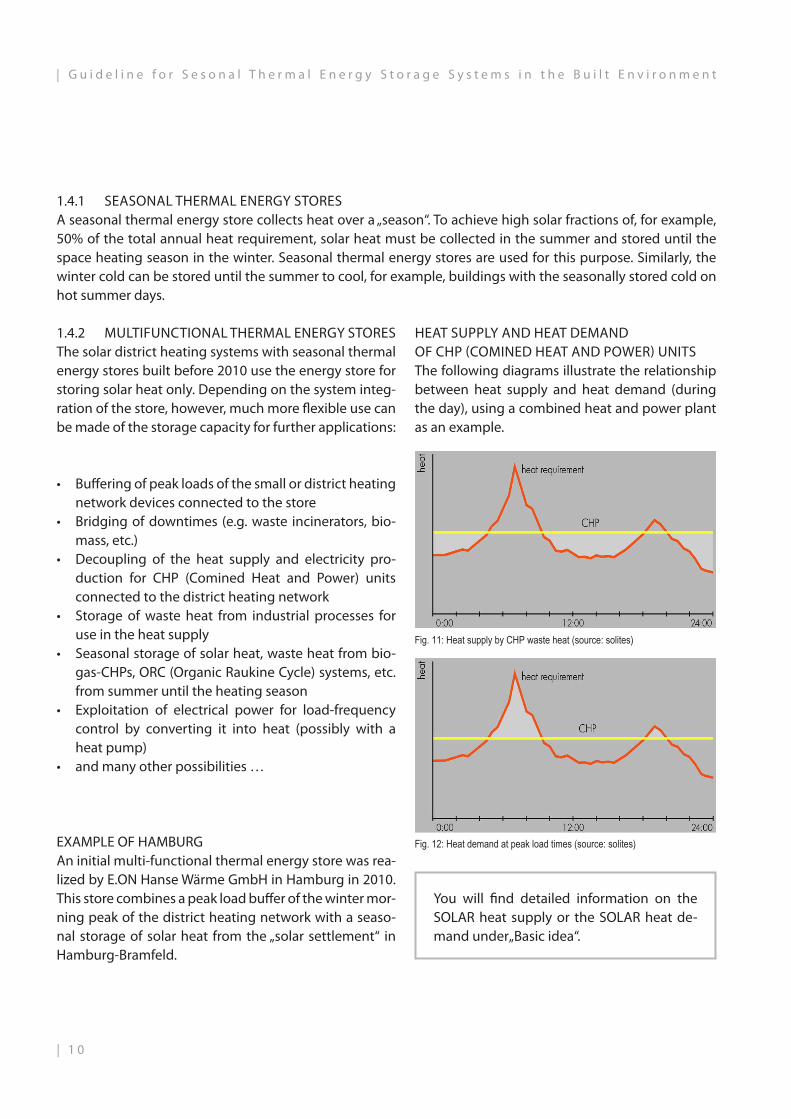
1.4.1 SEASONAL THERMAL ENERGY STORESA seasonal thermal energy store collects heat over a „season“. To achieve high solar fractions of, for example, 50% of the total annual heat requirement, solar heat must be collected in the summer and stored until the space heating season in the winter. Seasonal thermal energy stores are used for this purpose. Similarly, the winter cold can be stored until the summer to cool, for example, buildings with the seasonally stored cold on hot summer days.
HEAT SUPPLY AND HEAT DEMAND OF CHP (COMINED HEAT AND POWER) UNITSThe following diagrams illustrate the relationship between heat supply and heat demand (during the day), using a combined heat and power plant as an example.
You will find detailed information on the SOLAR heat supply or the SOLAR heat de-mand under„Basic idea“.
• Buffering of peak loads of the small or district heating network devices connected to the store
• Bridging of downtimes (e.g. waste incinerators, bio-mass, etc.)
• Decoupling of the heat supply and electricity pro-duction for CHP (Comined Heat and Power) units connected to the district heating network
• Storage of waste heat from industrial processes for use in the heat supply
• Seasonal storage of solar heat, waste heat from bio-gas-CHPs, ORC (Organic Raukine Cycle) systems, etc. from summer until the heating season
• Exploitation of electrical power for load-frequency control by converting it into heat (possibly with a heat pump)
• and many other possibilities …
EXAMPLE OF HAMBURGAn initial multi-functional thermal energy store was rea-lized by E.ON Hanse Wärme GmbH in Hamburg in 2010. This store combines a peak load buffer of the winter mor-ning peak of the district heating network with a seaso-nal storage of solar heat from the „solar settlement“ in Hamburg-Bramfeld.
Fig. 11: Heat supply by CHP waste heat (source: solites)
Fig. 12: Heat demand at peak load times (source: solites)
1.4.2 MULTIFUNCTIONAL THERMAL ENERGY STORESThe solar district heating systems with seasonal thermal energy stores built before 2010 use the energy store for storing solar heat only. Depending on the system integ-ration of the store, however, much more flexible use can be made of the storage capacity for further applications:
| 1 0
| G u i d e l i n e f o r S e s o n a l T h e r m a l E n e r g y S t o r a g e S y s t e m s i n t h e B u i l t E n v i r o n m e n t

1.4.3 BUFFER STORAGEA buffer storage device stores heat or cold for short periods, usually only a few hours or days.
DIMENSIONINGCharging and discharging are usually dictated by the heat generator and heat consumption and determi-ne the dimensioning of the thermal energy store as well as the charging and discharging devices. Like-wise, the total amount of heat to be stored must be taken into account when dimensioning the thermal energy store.
1.5 APPLICATION POSSIBILITIES
Except for the seasonal storage of solar thermal ener-gy, there are yet more ways of using seasonal ther-mal energy storage. Advanced technologies that necessarily require high-volume seasonal thermal storage are being developed and disseminated. The following examples are noteworthy…
CHARGING AND DISCHARGING + CONSTRUCTION METHODIf the buffer storage device is often charged and discharged, its storage cycle number is high. The higher this is, the lower is the heat loss relative to the amount of stored heat. That is why, for many buffers, the type and thickness of the insulation is not as crucial for storage efficiency as with seasonal thermal energy storage.For large amounts of heat to be stored, construction methods normally used for seasonal thermal energy sto-rage can be applied. Due to the obligatory charging and discharging, however, water-filled constructions of tank and pit thermal energy stores are usually preferable to those that make direct use of the ground.
Fig. 13: The diagram shows a cross-sectional view of a buffer storage system (source: solites)
• Increased use of biomass to generate electricity• Expansion of the use of geothermal energy and
the like• Increased use of waste heat in industry• Increased use of the waste heat produced during
the generation of electricity in power plants.• In this case, heat stores can compensate for fluc-
tuations in the demand for thermal power and de-couple the power supply from the heat supply by means of heat storage.
PREREQUISITESThese thermal energy stores usually require a lar-ge volume, since large amounts of heat have to be stored. They also need to operate reliably, be built at a reasonable price and to be usually (partly) inte-grated into the subsoil. Such thermal energy stores also have lower construction costs, because the sub-surface also helps to bear the static load of the water filling them, thus making construction of such stores more cost-effective.There are also large aboveground thermal energy stores, such as steel tanks more than 30 m high. How-ever, due to their height they can only be used in in-dustrial zones, next to large power plants and the like.
1 1 |
G u i d e l i n e f o r S e s o n a l T h e r m a l E n e r g y S t o r a g e S y s t e m s i n t h e B u i l t E n v i r o n m e n t |

2. TYPES OF STORES
2.1 OVERVIEW
The following four storage technologies are currently being investigated in pilot projects:
TANK thermal energy stores usually consist of an underground concrete tank filled with water.
PIT thermal energy stores come about by creating an artificial „pond“, filling it with storage material and then sealing it with a lid.
BOREHOLE thermal energy stores use – with the aid of geothermal probes through which water flows – the bedrock to store heat.
AQUIFER thermal energy stores use underground water-bearing strata for storing heat that can be accessed by wells.
| 1 2
| G u i d e l i n e f o r S e s o n a l T h e r m a l E n e r g y S t o r a g e S y s t e m s i n t h e B u i l t E n v i r o n m e n t

2.2 TANKS
Tank thermal energy storage systems consist of a large water tank connected to a charging and discharging circuit. If heat is available for charging, this is usually conducted into the tank through the heat transfer medi-um of water and extracted when needed. The body is made of concrete, steel or plastic and is usually insulated.
2.2.1 STRUCTURETank thermal energy stores are largely reinforced concrete containers built into the ground, the tanks being cast using in-situ concrete. Recent research projects work with precast concrete structures that are pretensioned on site and so can transfer higher loads or even stand under internal pressure.Inside, the tank is sealed with stainless steel or black steel. As substitutes for the liner and the concrete
structures, new GRP or steel structures are now a pos-sibility. In Hamburg, a novel design of a stainless steel vessel that was wound directly from the sheet metal coil and welded was carried out in 2010.The floor, walls and roof of tank thermal energy stores are insulated to prevent heat loss. Depending on the load situation, foam glass gravel is used to insulate the floor and expanded glass granulate in a membra-ne formwork is used for the walls and roof.
2.2.2 STORAGE MATERIALTank thermal energy stores designed for temperatures up to 120° C are filled with water, since water offers ex-cellent heat storage capacity. It is highly suitable as a heat transfer medium, because it is chemically harmless, easy to handle and can be easily integrated into the hydraulic system.With unpressurised tanks, the storage medium can be heated up to 95° C. At higher temperatures, the water would boil and evaporate. However, since steam has an about 1,600-fold greater volume than water, such a store would no longer be able to withstand the internal pressure (caused by the vapour).If the tank is under internal pressure due to its construction and is steam-tight, significantly higher tempera-tures can be fed into it.
Fig. 14: Construction method of a thank thermal energy store (source: solites)
1 3 |
G u i d e l i n e f o r S e s o n a l T h e r m a l E n e r g y S t o r a g e S y s t e m s i n t h e B u i l t E n v i r o n m e n t |

2.2.3 CHARGING AND DISCHARGINGThe tank thermal energy storage unit is charged and discharged by means of pipelines.The temperature stratification of the water is carried out automatically via the density of the medium: hot water is less dense and therefore rises; cold water, on the other hand, collects at the bottom.For charging, a stratification device is used, which feeds the heated water into the tank during charging phase, in accordance with its temperature. This is ne-cessary to prevent any mixing of the layers and thus any cooling of temperature inside the store. Using this device, the hot water can be directly (i.e. without any additional use of heat pumps or top-up heating) used when the heat has to be discharged.To discharge or extract the heat during the heating season, the water is withdrawn from the top, i.e. the hottest part of the heat store.Seasonal thermal energy stores with a pure or high water content are high-performance systems that have low inertia: the stored heat can be discharged with high volume flows and short access times.
2.2.5 SIZEOnly as of a water volume of 1,000 m³ does seasonal thermal energy storage start to become energy ef-ficient; below that size, the volume-related heat loss of the store is too high. The sizes of constructed tank thermal energy stores range from 2,750 m³ to 12,000 m³. Tank thermal energy stores with GRP construc-tion seem to be suitable for a storage volume of up to roughly 6,000 m³. Tank thermal energy stores have a thermal storage capacity of 60-80 kWh/m³.
2.2.4 REQUIREMENTSTank thermal energy stores are mostly situated un-derground and can be integrated as a hill that people in the settlement supplied by it can walk on. The con-dition of the subsurface should be stable and, if pos-sible, have no groundwater at a depth of 5 m to 15 m.
SPECIAL FEATUREOf all storage types, tank thermal energy sto-rage systems exhibit the most favourable con-ditions for optimising the A/V ratio and thus minimising storage heat losses.
Fig. 16: Integration of a thermal storage hill into the landscape(source: raum+)
Fig. 15: Schematic size and proportions of a thank thermal energy store (source: solites)
| 1 4
| G u i d e l i n e f o r S e s o n a l T h e r m a l E n e r g y S t o r a g e S y s t e m s i n t h e B u i l t E n v i r o n m e n t

2.3 PITS
Pit thermal energy storage systems consist of a large, enclosed and (partially) insulated pit in the ground, which can be filled with various storage media. By means of wells or pipelines, heat is directly or indirectly conducted into the store, and extracted when needed. The roof usually only lies on the store filling.
2.3.1 STRUCTUREPit thermal energy stores are dug into the ground to a depth of 5 m to 15 m. The side walls are supported by shotcrete or its equivalent using a Berlin type pit lining or they are naturally sloped i.e. inclined. The angle of slope depends on the soil conditions. The thermal energy store is usually insulated all round against the ground by means of expanded glass gra-nulate in fabric bags or by membrane formwork – very large storage volumes were realised in Denmark without any thermal insulation in walls and bottom. At the top, the basin is sealed by a floating, cantile-vered or fixed lid, which is likewise insulated.
SPECIAL FEATURESIn contrast to tank thermal energy stores, pit thermal energy stores are rather flat and have a large surface area. The angle of slope and the maximum installation depth are limited by the nature and density of the supporting soil.
Fig. 18: German design with usable roof (source: solites)
Fig. 19: Danish design with NON-usable roof (source: solites)
Fig. 17: Construction method of a pit thermal energy store (source: solites)
1 5 |
G u i d e l i n e f o r S e s o n a l T h e r m a l E n e r g y S t o r a g e S y s t e m s i n t h e B u i l t E n v i r o n m e n t |

HEAT CAPACITY
Water: 4190 kJ/m³KGravel: 2800 kJ/m³K
2.3.2 CHARGING AND DISCHARGINGThe pit thermal energy store is charged and dischar-ged by means of water-filled pipes. To discharge the heat during the heating season, water is extracted from the hottest part of the store. A distinction is made between direct and indirect charging.
DIRECT CHARGING AND DISCHARGINGWith direct charging, the heated water is conducted directly into the store and likewise extracted from it. Possible contamination by the storage material (e.g. earth and gravel) could cause clogging of the discharge pipes (feed), which must be prevented by means of filters.
INDIRECT CHARGING AND DISCHARGINGIndirectly charged stores are crisscrossed by water-proof plastic pipelines which supply heat to the sto-rage material – i.e. the load water circuit does not come into contact with the storage material. Indirect discharge is also carried out via the water-carrying pipes, with the difference that the storage material transfers the heat to the heat transfer medi-um (opposite heat flow).With indirect charging and discharging, additional heat losses can be expected through the heat trans-fer process.
SPECIAL FEATUREIf the pit thermal store is filled exclusively with water, a stratification device can be used for charging in or-der to achieve an advantageous temperature stratifi-cation in the storage device.
TERMINOLOGY
The heat transfer material is usually water.
The plastic pipe through which the heat is released into the store is refer-red to as a heat exchanger
Fig. 20: Direct charging and discharging (source: solites) Fig. 21: Indirect charging and discharging (source: solites)
Fig. 22: Pipes for indirect charging and discharging (source: solites)
| 1 6
| G u i d e l i n e f o r S e s o n a l T h e r m a l E n e r g y S t o r a g e S y s t e m s i n t h e B u i l t E n v i r o n m e n t
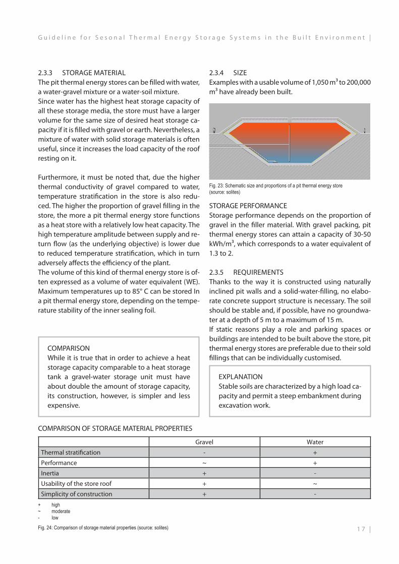
2.3.4 SIZEExamples with a usable volume of 1,050 m³ to 200,000 m³ have already been built.
Fig. 23: Schematic size and proportions of a pit thermal energy store (source: solites)
STORAGE PERFORMANCEStorage performance depends on the proportion of gravel in the filler material. With gravel packing, pit thermal energy stores can attain a capacity of 30-50 kWh/m³, which corresponds to a water equivalent of 1.3 to 2.
2.3.5 REQUIREMENTSThanks to the way it is constructed using naturally inclined pit walls and a solid-water-filling, no elabo-rate concrete support structure is necessary. The soil should be stable and, if possible, have no groundwa-ter at a depth of 5 m to a maximum of 15 m.If static reasons play a role and parking spaces or buildings are intended to be built above the store, pit thermal energy stores are preferable due to their sold fillings that can be individually customised.
COMPARISON OF STORAGE MATERIAL PROPERTIES
EXPLANATIONStable soils are characterized by a high load ca-pacity and permit a steep embankment during excavation work.
COMPARISONWhile it is true that in order to achieve a heat storage capacity comparable to a heat storage tank a gravel-water storage unit must have about double the amount of storage capacity, its construction, however, is simpler and less expensive.
2.3.3 STORAGE MATERIALThe pit thermal energy stores can be filled with water, a water-gravel mixture or a water-soil mixture.Since water has the highest heat storage capacity of all these storage media, the store must have a larger volume for the same size of desired heat storage ca-pacity if it is filled with gravel or earth. Nevertheless, a mixture of water with solid storage materials is often useful, since it increases the load capacity of the roof resting on it.
Furthermore, it must be noted that, due the higher thermal conductivity of gravel compared to water, temperature stratification in the store is also redu-ced. The higher the proportion of gravel filling in the store, the more a pit thermal energy store functions as a heat store with a relatively low heat capacity. The high temperature amplitude between supply and re-turn flow (as the underlying objective) is lower due to reduced temperature stratification, which in turn adversely affects the efficiency of the plant.The volume of this kind of thermal energy store is of-ten expressed as a volume of water equivalent (WE). Maximum temperatures up to 85° C can be stored In a pit thermal energy store, depending on the tempe-rature stability of the inner sealing foil.
+ high~ moderate- low
Fig. 24: Comparison of storage material properties (source: solites)
Gravel Water
Thermal stratification - +
Performance ~ +
Inertia + -
Usability of the store roof + ~
Simplicity of construction + -
1 7 |
G u i d e l i n e f o r S e s o n a l T h e r m a l E n e r g y S t o r a g e S y s t e m s i n t h e B u i l t E n v i r o n m e n t |
2.4 BOREHOLE THERMAL ENERGY STORES
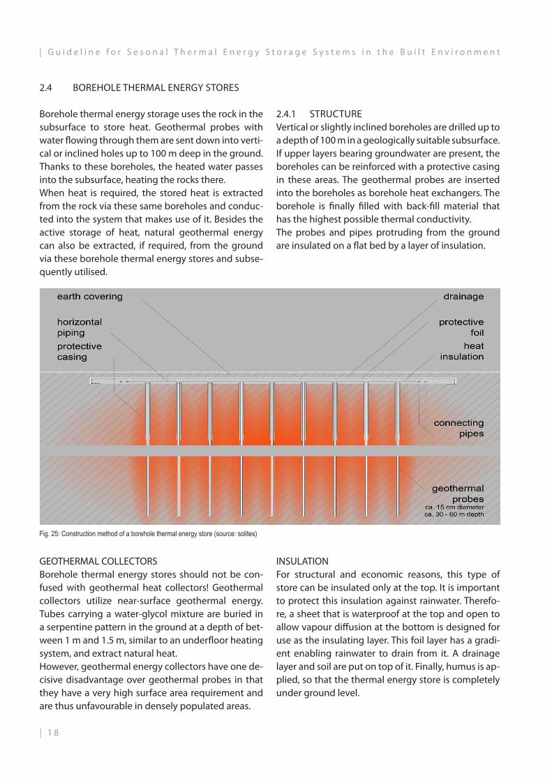
Borehole thermal energy storage uses the rock in the subsurface to store heat. Geothermal probes with water flowing through them are sent down into verti-cal or inclined holes up to 100 m deep in the ground. Thanks to these boreholes, the heated water passes into the subsurface, heating the rocks there.When heat is required, the stored heat is extracted from the rock via these same boreholes and conduc-ted into the system that makes use of it. Besides the active storage of heat, natural geothermal energy can also be extracted, if required, from the ground via these borehole thermal energy stores and subse-quently utilised.
Fig. 25: Construction method of a borehole thermal energy store (source: solites)
GEOTHERMAL COLLECTORSBorehole thermal energy stores should not be con-fused with geothermal heat collectors! Geothermal collectors utilize near-surface geothermal energy. Tubes carrying a water-glycol mixture are buried in a serpentine pattern in the ground at a depth of bet-ween 1 m and 1.5 m, similar to an underfloor heating system, and extract natural heat.However, geothermal energy collectors have one de-cisive disadvantage over geothermal probes in that they have a very high surface area requirement and are thus unfavourable in densely populated areas.
2.4.1 STRUCTUREVertical or slightly inclined boreholes are drilled up to a depth of 100 m in a geologically suitable subsurface. If upper layers bearing groundwater are present, the boreholes can be reinforced with a protective casing in these areas. The geothermal probes are inserted into the boreholes as borehole heat exchangers. The borehole is finally filled with back-fill material that has the highest possible thermal conductivity.The probes and pipes protruding from the ground are insulated on a flat bed by a layer of insulation.
INSULATIONFor structural and economic reasons, this type of store can be insulated only at the top. It is important to protect this insulation against rainwater. Therefo-re, a sheet that is waterproof at the top and open to allow vapour diffusion at the bottom is designed for use as the insulating layer. This foil layer has a gradi-ent enabling rainwater to drain from it. A drainage layer and soil are put on top of it. Finally, humus is ap-plied, so that the thermal energy store is completely under ground level.
| 1 8
| G u i d e l i n e f o r S e s o n a l T h e r m a l E n e r g y S t o r a g e S y s t e m s i n t h e B u i l t E n v i r o n m e n t

Fig. 26: Insulation of geothermal probe pipes (source: solites)
2.4.2 STORAGE MATERIALBorehole heat storage systems feed heat into the na-tural subsurface, which, depending on its compositi-on, has different heat capacities and can be heated up to about 80° C. Geothermal probes are especially useful in a subsurface with a high heat capacity and impermeability, e.g. in water-saturated clays and rock strata. These are favourable because they are rarely subjected to groundwater movements that would cause heat losses.
INERTIASince heat conduction in soil is relatively slow com-pared to water, these solid state stores have a longer access time than tank thermal energy storage units; this is called "inertia". Thus, borehole thermal energy stores cannot buffer power peaks of heat suppliers and are often used in conjunction with less sluggish buffers and heat pumps.
2.4.3 CHARGING AND DISCHARGINGThe heat gained is conducted into the probes, in which water circulates as the heat carrier. When the store is charged during the solar season, the water transfers the solar heat to the filling material in the borehole, and this, in turn, transfers the heat to the subsurface.In the heating phase, the borehole heat exchangers are fed with cooler water and extract the stored heat from the subsurface. In general, when the store is charged, the water passes through it from the inside to the outside, and when the heat is discharged, the direction of flow is reversed.
GEOTHERMAL PROBESVertical or inclined underground heat pipe-lines that make thermal use of the subsurface;(Drilling depths: 20 m to more than 100 m)
Fig. 28: Geothermal probe head, source: REHAU Fig. 29: Charging and discharging scheme of a borehole thermal energy store (source: solites)
Fig. 27: Diagrammatic cross-section of a geothermal probe (source: solites)
1 9 |
G u i d e l i n e f o r S e s o n a l T h e r m a l E n e r g y S t o r a g e S y s t e m s i n t h e B u i l t E n v i r o n m e n t |

Fig. 30: Schematic size and proportions of a borehole thermal energy store (source: solites)
2.4.4 SIZEBorehole thermal energy stores are accessed via a geothermal probe field. The probe field should have the best possible A/V ratio with nevertheless minimal drilling.The boreholes for the geothermal probes have a dia-meter of about 0.1 m – 0.2 m and require a horizontal gap of 1.5 m – 3 m between each of them. Usually, numerous boreholes are combined to form a probe field – e.g. 80 units in the first phase of construction in Crailsheim. Such kinds of storage volumes range from 9,350 m³ in Attenkirchen to 37,500 m³ in Crails-heim and even up to 63,300 m³ in Neckarsulm.
COST-EFFECTIVENESSWhat make energetic and financial sense are storage volumes larger than 20,000 m³, because only the top of the storage unit can be insulated, which is why high heat losses result. This disadvantage is com-pensated by a sufficiently good A/V ratio. Borehole thermal energy storage systems can achieve heat densities of 15-30 kWh/m³, corresponding to a water equivalent of 3 – 6.
CALCULATION OF THE STORAGE VOLUMEA rough estimate can be done by comparing the heat capacity of soil and water. As a storage material, soil has an average of only 20% – 25% of the storage ca-pacity of water, thus resulting in borehole heat sto-rage systems of a volume four to five times larger if one wishes to store the same amount of heat.An exact calculation must be done by means of a sys-tem comparison, in which the system integration and the system components – such as heat pumps or buf-fers – are taken into account. This, however, is a very complicated and complex procedure.Nevertheless, the volume of borehole thermal ener-gy stores cannot be precisely determined due to a lack of a boundary and the different thermal conduc-tivities of the adjacent rock strata.
Fig. 31: Diagrammatic section through a geothermal probe thermal energy store (source: solites)| 2 0
| G u i d e l i n e f o r S e s o n a l T h e r m a l E n e r g y S t o r a g e S y s t e m s i n t h e B u i l t E n v i r o n m e n t

VARIABLES FOR A SYSTEMS COMPARISON
• System components• System integration• Storage capacities• Heat capacities• Type of thermal energy store
2.4.5 REQUIREMENTS
Borehole thermal energy stores should be installed for economic reasons only in well drillable subsur-faces. It should be ensured that no groundwater leaks out due to heat losses in the ground drilled through. In this case, the active storage depth may have to be limited. Extensive geological preliminary investiga-tions must be carried out in any event; any existing drinking water must on no account be adversely af-fected.Geothermal probe fields are protected by the co-vering layer, which can be used as an open space wi-thout restriction. Plants with strong roots may not be planted.
Fig. 32: Example of the open space design of borehole thermal energy store (source: solites)
2 1 |
G u i d e l i n e f o r S e s o n a l T h e r m a l E n e r g y S t o r a g e S y s t e m s i n t h e B u i l t E n v i r o n m e n t |
2.5 AQUIFER THERMAL ENERGY STORE
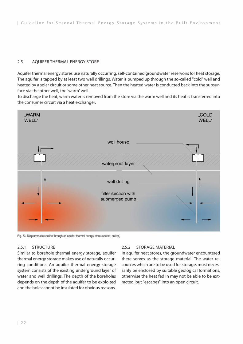
Aquifer thermal energy stores use naturally occurring, self-contained groundwater reservoirs for heat storage. The aquifer is tapped by at least two well drillings. Water is pumped up through the so-called "cold" well and heated by a solar circuit or some other heat source. Then the heated water is conducted back into the subsur-face via the other well, the 'warm' well.To discharge the heat, warm water is removed from the store via the warm well and its heat is transferred into the consumer circuit via a heat exchanger.
2.5.1 STRUCTURESimilar to borehole thermal energy storage, aquifer thermal energy storage makes use of naturally occur-ring conditions. An aquifer thermal energy storage system consists of the existing underground layer of water and well drillings. The depth of the boreholes depends on the depth of the aquifer to be exploited and the hole cannot be insulated for obvious reasons.
2.5.2 STORAGE MATERIALIn aquifer heat stores, the groundwater encountered there serves as the storage material. The water re-sources which are to be used for storage, must neces-sarily be enclosed by suitable geological formations, otherwise the heat fed in may not be able to be ext-racted, but "escapes" into an open circuit.
Fig. 33: Diagrammatic section through an aquifer thermal energy store (source: solites)
| 2 2
| G u i d e l i n e f o r S e s o n a l T h e r m a l E n e r g y S t o r a g e S y s t e m s i n t h e B u i l t E n v i r o n m e n t

2.5.3 CHARGING AND DISCHARGINGWith aquifer thermal energy storage, heat transfer is effected by a direct exchange of the groundwater. When the store is charged, it is taken from the "cold" well (or group of wells), heated by the heat sour-ce (e.g. solar collectors, heat, etc.) and reintroduced into the subsurface via a "hot" well (or well group). In this case, two temperature levels, completely se-parate from each other, arise around the respective wells on (or well groups), which depend primarily on the charging and discharging conditions. During operation, horizontal temperature stratification ari-ses in individual wells, starting from the well centre outwards. It also has, however, a vertical component due to thermal losses into the overlying stratum and soil stratum.
Fig. 35: Wellhead in the well house (source: solites)
Fig. 34: Installation of the well pipe (source: solites)
2.5.5 SIZEThe volume of the aquifer thermal energy store de-pends on the naturally occurring aquifer and the quantity of heat to be stored. In Rostock, an aquifer of 20,000 m³ was developed for storing solar heat. The well drillings are the only visible part of the store above ground.
Fig. 36 Schematic size and proportions of an aquifer thermal energy store (source: solites)
CALCULATION OF THE STORAGE VOLUMEEstimating the storage size of aquifers is more com-plex than estimating the size of borehole thermal energy stores because, in this case, water is not only heat exchanger, but also the storage material at the same time. Due to any lack of a boundary, the way the water is distributed in the rock layers depends on their properties, and they also have different heat ca-pacities. This means that the storage capacity of aqui-fer thermal energy stores can be estimated with an accuracy of only 20 - 30%.
2.5.4 REQUIREMENTSAquifer thermal energy stores cannot be constructed but are only developed when they are already pre-sent in the planning area anyway. The on-site water resources have to be accompanied by suitably dense geological formations. Not every self-contained aqui-fer is suitable for seasonal thermal energy storage – a minimum volume and, above all, a minimum layer thickness must be present.
SPECIAL FEATURESDue to their minimal design requirements compared to other heat storage systems, aquifer thermal ener-gy storage systems are among the most cost-effec-tive heat storage systems when based on volume. However, complex preliminary geological studies and constant monitoring of the subsurface and wa-ter during operation are strictly necessary in order to protect any existing drinking water resources and to avoid any hydrogeological changes.
2 3 |
G u i d e l i n e f o r S e s o n a l T h e r m a l E n e r g y S t o r a g e S y s t e m s i n t h e B u i l t E n v i r o n m e n t |

2.6 MODULAR CONSTRUCTION PRINCIPALS
Sesonal Thermal Energy Stores (STES) have to store thermal energy for one season. Thus the storage vo-lume is still unfamiliar big compared to the building, settlement area or equal for that the STES is realized. Due to this big size there is the general impression that it might be difficult to find space for realizing the storage especially in existing applications. Regarding multi family buildings in urban areas it is obvious that there is only little space inside the building. On the other hand, one might compare the space that is needed for STES with the space that is kept at hand for parking all the individual cars of the residents of the building.If the freedom in project development allows to take the surrounding into account or to develop the pro-ject into regarding the district, most studies and pro-jects have shown that it was not difficult to find an appropriate place for realization of the STES. When STES should be integrated in urban areas, im-portant is that the STES can be integrated into the townscape by placing it underground or at least built it partly ground buried. A second important advan-tage is that most of the STES technologies can provi-de a STES surface that is usable in a familiar way. Thus a STES can be placed under a car-park, in the garden, in the district green, combined with a children play-ground, in a schoolyard, in the city park etc.
MODULAR STORAGE CONCEPTSModular storage concepts concern two main approaches:• Developing a storage volume over years by
growing it up in few steps.• Building a certain storage volume out of
single modules.
2.6.1 STES CONCEPTS FOR ENLARGING THE VOLUME STEPWISEIf the system the STES has to be integrated in is in de-velopment for a lot of years it might be of advantage to start with a smaller storage volume and increase the volume stepwise according to the heating needs of the growing heating system.Since the first years of STES development in the late 1970s in STUDSVIK laboratories in Sweden, through the first years of international research within IEA SHC Task 7 and further on, scientists showed high crea-tivity in developing ideas how STES can be built in several building stages. Although a lot of ideas were theoretically developed, all closer analyses together with building industries came to the same result: it is too expensive to invest in a lot of material, to prepare the building stage several times etc., if you use the storage you build only once or twice a year – as it is characteristic for STES.If a multifunctional heat storage is used also as buffer storage resulting in that the entire storage volume is used typically between 300 to 600 times per year, the economics of investing more money to realize the fi-nal storage volume might be very promising, but for STES it can only be looked on storage technologies that easily can be build in modules.This advantage is only offered by BTES as shown in one of the first BTES pilot plants that was realized in Neckarsulm, Germany over some years. Figure 37 gi-ves a top view on the storage ground showing the building stages.
All modular storage concepts show the charac-teristic that building up a storage out of mo-dules is cost-intensive due to the effect that it needs a lot of working hours at the building site. Thus these technologies show unconvin-cing economics if applied for STES.
| 2 4
| G u i d e l i n e f o r S e s o n a l T h e r m a l E n e r g y S t o r a g e S y s t e m s i n t h e B u i l t E n v i r o n m e n t
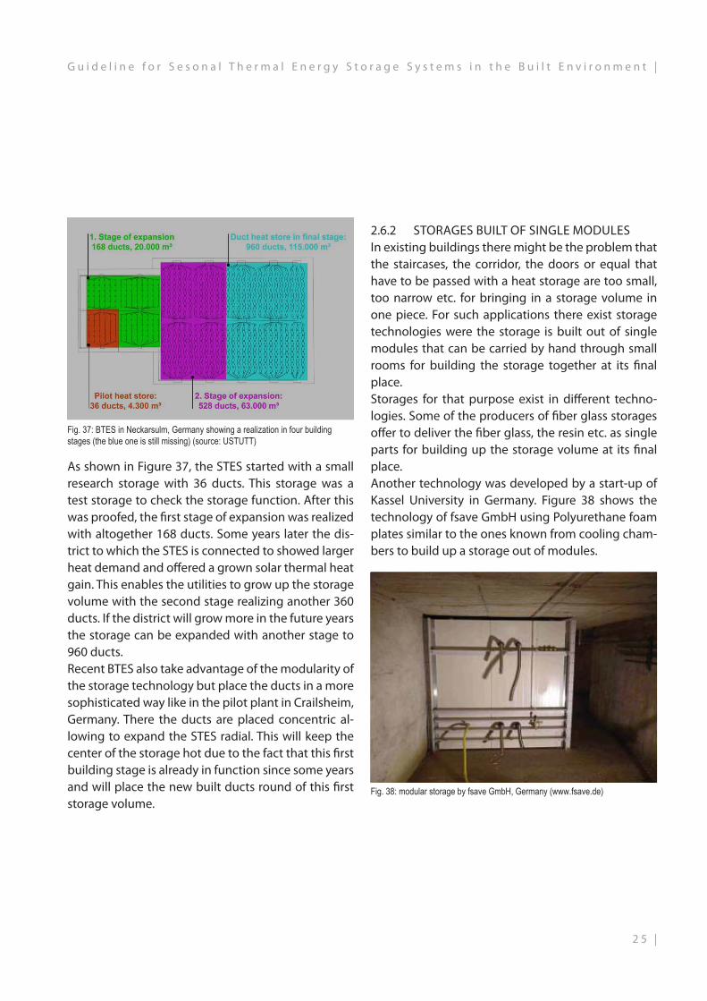
Fig. 37: BTES in Neckarsulm, Germany showing a realization in four building stages (the blue one is still missing) (source: USTUTT)
As shown in Figure 37, the STES started with a small research storage with 36 ducts. This storage was a test storage to check the storage function. After this was proofed, the first stage of expansion was realized with altogether 168 ducts. Some years later the dis-trict to which the STES is connected to showed larger heat demand and offered a grown solar thermal heat gain. This enables the utilities to grow up the storage volume with the second stage realizing another 360 ducts. If the district will grow more in the future years the storage can be expanded with another stage to 960 ducts.Recent BTES also take advantage of the modularity of the storage technology but place the ducts in a more sophisticated way like in the pilot plant in Crailsheim, Germany. There the ducts are placed concentric al-lowing to expand the STES radial. This will keep the center of the storage hot due to the fact that this first building stage is already in function since some years and will place the new built ducts round of this first storage volume.
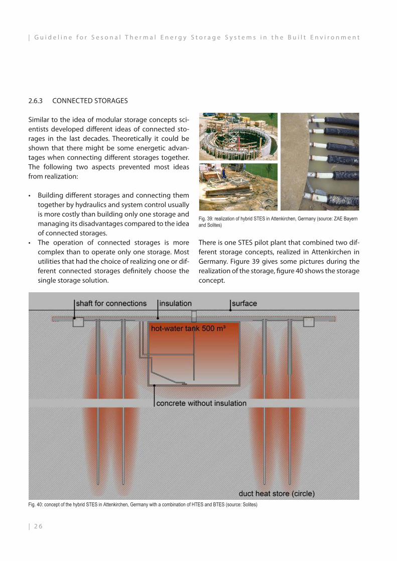
2.6.2 STORAGES BUILT OF SINGLE MODULESIn existing buildings there might be the problem that the staircases, the corridor, the doors or equal that have to be passed with a heat storage are too small, too narrow etc. for bringing in a storage volume in one piece. For such applications there exist storage technologies were the storage is built out of single modules that can be carried by hand through small rooms for building the storage together at its final place. Storages for that purpose exist in different techno-logies. Some of the producers of fiber glass storages offer to deliver the fiber glass, the resin etc. as single parts for building up the storage volume at its final place. Another technology was developed by a start-up of Kassel University in Germany. Figure 38 shows the technology of fsave GmbH using Polyurethane foam plates similar to the ones known from cooling cham-bers to build up a storage out of modules.
Fig. 38: modular storage by fsave GmbH, Germany (www.fsave.de)
2 5 |
G u i d e l i n e f o r S e s o n a l T h e r m a l E n e r g y S t o r a g e S y s t e m s i n t h e B u i l t E n v i r o n m e n t |
2.6.3 CONNECTED STORAGES
Similar to the idea of modular storage concepts sci-entists developed different ideas of connected sto-rages in the last decades. Theoretically it could be shown that there might be some energetic advan-tages when connecting different storages together. The following two aspects prevented most ideas from realization:
• Building different storages and connecting them together by hydraulics and system control usually is more costly than building only one storage and managing its disadvantages compared to the idea of connected storages.
• The operation of connected storages is more complex than to operate only one storage. Most utilities that had the choice of realizing one or dif-ferent connected storages definitely choose the single storage solution.
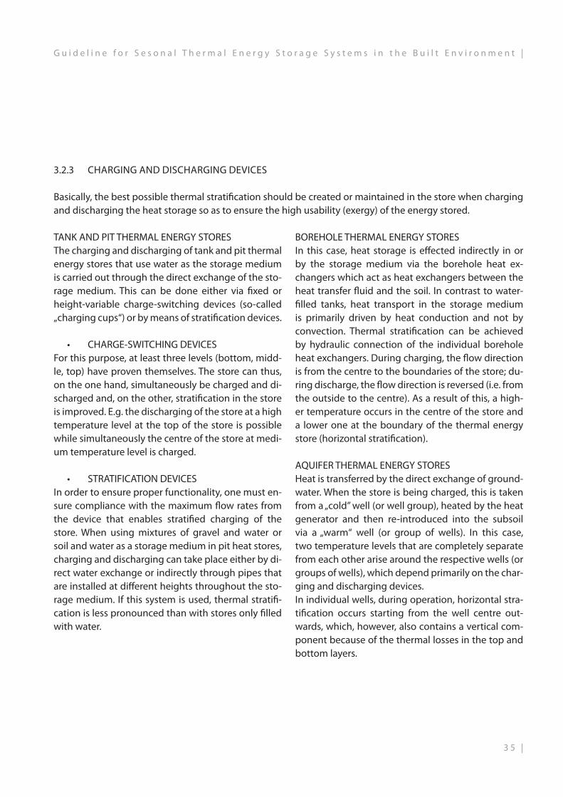
There is one STES pilot plant that combined two dif-ferent storage concepts, realized in Attenkirchen in Germany. Figure 39 gives some pictures during the realization of the storage, figure 40 shows the storage concept.
Fig. 39: realization of hybrid STES in Attenkirchen, Germany (source: ZAE Bayern and Solites)
Fig. 40: concept of the hybrid STES in Attenkirchen, Germany with a combination of HTES and BTES (source: Solites)
| 2 6
| G u i d e l i n e f o r S e s o n a l T h e r m a l E n e r g y S t o r a g e S y s t e m s i n t h e B u i l t E n v i r o n m e n t

As shown in Figure 40 the idea of the hybrid STES is to build a medium sized HTES giving a water volu-me that easily can be loaded and unloaded with high peak loads. To keep it on favorable cost no heat in-sulation is adapted to the storage volume realized as concrete cylinder. The heat losses flow to a concentri-cal BTES with ducts taking up the heat loss from the HTES and, in addition, some geothermal energy from the deeper surrounding.The technical system delivers a heat pump for coll-ecting the heat losses of the HTES through BTES and “pump it back” into the HTES. A second heat pump delivers heat to the connected district heating net if the temperature delivered by the HTES is lower than the needed supply temperature.Due to the two heat pumps the entire system shows high electric power consumption. The practical ope-ration of the complex system showed some challen-ges for the operator that was not used to operate such complex systems.
2.6.4 VIRTUAL DECENTRALIZED LARGE SCALE STORAGES
If it might be difficult to realize a large STES it seems to be a smart idea to build smaller, but also large sca-le storages decentralized, e.g. in every building of a district heating system for which a STES is in conside-ration. Since the mid of the 1990s this idea raised in several pilot plants and in (very) few of the first solar assisted district heating systems, that are located in rural areas in Austria and that are mainly based on woodchip burners, this concept was realized (see e.g. www.solid.at).These systems show similar outcomes like several energy concepts that were realized within central European countries: The realization of a lot of smaller storage volumes, the more complex heat transfer in the single houses, the realization of the entire system control and the practical operation show impressive cost that easily are higher compared to a technical alternative with centralized STES. Thus until today all pilot plants with a seasonal storing of heat use cen-tralized STES although often a decentralized variant was studied.
2 7 |
G u i d e l i n e f o r S e s o n a l T h e r m a l E n e r g y S t o r a g e S y s t e m s i n t h e B u i l t E n v i r o n m e n t |

2.7 ADAPTABILITY FOR INTEGRATION IN EXISTING BUILDING STRUCTURES
2.7.1 STATE-OF-THE-ARTEspecially in retrofitting applications possible limi-tations in space for STES might lead to the necessity for investigation of small scale TES. The typical small scale storage is a buffer storage made of standard steel. If new, even larger buffer storages are needed in retrofitting applications, there occur often obsta-cles like:
• The buffer storage is too wide for the staircase it should pass on its way into the technical room
• The buffer storage is enough slim to pass the stair-case, but the door into the technical room is too narrow.
• The buffer storage is too high for the technical room.
• The technical room offers no place for integrating the buffer storage.
•In cases where some of the first three points apply a often used solution is to devide the needed buffer volume up in some smaller buffer storages and to realize a “buffer storage collection” in the technical room. An example is shown in figure 41.
This “collection” of buffer storages raise the challenge to connect and operate the different volumes in an energy efficient way.If the retrofitting work comprises some structural work in the building itself, it might be applicable to integrate the needed buffer volume in one big sto-rage that goes over two floors, e.g. through the for-mer ceiling of the technical room. An example for this solution is shown in figure 42.
Fig. 41: “Collection” of buffer storages in retrofitting application where a larger sto-rage could not pass the way into the technical room (source: Solites)
Fig. 42: Integration of a large buffer storage in retrofitting application by using two floors and removing the floor in between (source: Solites)
2.7.2 NEW CONCEPTS FOR SMALL SCALE TES IN RETROFITTING APPLICATIONS
The two examples in figures 41 and 42 show that it is worth to regard alternatives to the conventional buf-fer storage, made of standard steel:A steel tank as TES must not always be the most suita-ble solution although its technical properties such as high temperature resistance, water and water vapor tightness or pressure resistance are of high quality.
| 2 8
| G u i d e l i n e f o r S e s o n a l T h e r m a l E n e r g y S t o r a g e S y s t e m s i n t h e B u i l t E n v i r o n m e n t

Fig. 43: Glass fiber reinforced plastic (GRP) tanks of company Haase (source: Haase GFK-Technik GmbH)
Another concept has been developed by the company fsave Solartechnik GmbH. They are also using plastics and other composite materials such as PUR-sandwich panels and a steel frame for their stores but in a cubical shape as shown in Fig. 44. This shape has the advantage to use the availa-ble space in buildings very efficient. Same as the stores of the company Haase their stores can be delivered in prefabricated parts, are easy to trans-port and will be assembled on site. Both described concepts mostly use the stores non-pressurized. That means they need internal or external heat exchangers for separating the different pressu-re levels of the system. For the internal heat ex-changers corrugated pipes are used.
Fig. 44: Cubical shaped store of company fsave Solartechnik GmbH (source: fsave Solartechnik GmbH)
Nevertheless, for short and medium term pur-poses and smaller scale applications, for which usually volumes of many hundred liters to seve-ral cubic meters are required, the steel tanks are most likely prefabricated. Consequently they have already their final shape before installation on site. Especially for retrofitting applications this can be a large disadvantage because they might not fit into the available space or can’t be transported to their final destination, as explained above. There-fore modular and easy transportable solutions are required. There are already some different solu-tions on the market, which will be presented in the following.The first concept is glass fiber reinforced plastic (GRP) tanks (see Fig. 43). They have a cylindrical shape and can be delivered in pieces. The cur-ved casing can be delivered in a coil and thus fits through narrow aisles and doors. All parts are then assembled on site.
Those first two concepts are mainly for indoor pur-poses. The company Mall is offering a product calling Thermosol for outdoor underground purposes (Fig. 45 and 46). Within a type of water cistern a steel tank or a steel coated shell will be installed and the gap between concrete tank and steel tank will be well insulated. This concept combines standard compo-nents for outdoor and underground applications. This has the advantage that only small space is requi-red. The stores are available as pressurized as well as non-pressurized types.
Fig. 45 and 46: Thermosol store of company Mall (source. Mall Umweltsysteme)
2 9 |
G u i d e l i n e f o r S e s o n a l T h e r m a l E n e r g y S t o r a g e S y s t e m s i n t h e B u i l t E n v i r o n m e n t |
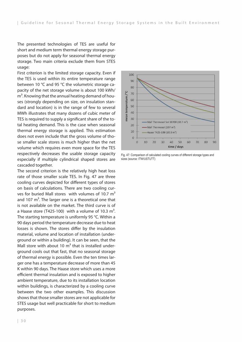
The presented technologies of TES are useful for short and medium term thermal energy storage pur-poses but do not apply for seasonal thermal energy storage. Two main criteria exclude them from STES usage:First criterion is the limited storage capacity. Even if the TES is used within its entire temperature range between 10 °C and 95 °C the volumetric storage ca-pacity of the net storage volume is about 100 kWh/m³. Knowing that the annual heating demand of hou-ses (strongly depending on size, on insulation stan-dard and location) is in the range of few to several MWh illustrates that many dozens of cubic meter of TES is required to supply a significant share of the to-tal heating demand. This is the case when seasonal thermal energy storage is applied. This estimation does not even include that the gross volume of tho-se smaller scale stores is much higher than the net volume which requires even more space for the TES respectively decreases the usable storage capacity especially if multiple cylindrical shaped stores are cascaded together. The second criterion is the relatively high heat loss rate of those smaller scale TES. In Fig. 47 are three cooling curves depicted for different types of stores on basis of calculations. There are two cooling cur-ves for buried Mall stores with volumes of 10.7 m³ and 107 m³. The larger one is a theoretical one that is not available on the market. The third curve is of a Haase store (T425-100) with a volume of 10.3 m³. The starting temperature is uniformly 95 °C. Within a 90 days period the temperature decrease due to heat losses is shown. The stores differ by the insulation material, volume and location of installation (under-ground or within a building). It can be seen, that the Mall store with about 10 m³ that is installed under-ground cools out that fast, that no seasonal storage of thermal energy is possible. Even the ten times lar-ger one has a temperature decrease of more than 45 K within 90 days. The Haase store which uses a more efficient thermal insulation and is exposed to higher ambient temperature, due to its installation location within buildings, is characterized by a cooling curve between the two other examples. This discussion shows that those smaller stores are not applicable for STES usage but well practicable for short to medium purposes.
Fig. 47: Comparison of calculated cooling curves of different storage types and sizes (source: ITW/USTUTT)
| 3 0
| G u i d e l i n e f o r S e s o n a l T h e r m a l E n e r g y S t o r a g e S y s t e m s i n t h e B u i l t E n v i r o n m e n t

3 1 |
G u i d e l i n e f o r S e s o n a l T h e r m a l E n e r g y S t o r a g e S y s t e m s i n t h e B u i l t E n v i r o n m e n t |

3.1 SYSTEM PROPERTIES
In a heat supply system, a seasonal thermal energy store is just one component of many and exhibits some properties that must be fully understood as they are crucial for plant design and operation.
3. SYSTEM TECHNOLOGY
MULTIPLE USESHeat storage economy can be improved if the ther-mal energy store is not only available to a solar ener-gy plant as a source of heat for example, but if – in parallel or at times when it is not used – other sour-ces of heat can be used, for example, for peak load buffering (e.g. storage of CHP waste heat, operatio-nal optimisation of biomass boilers, etc.). However, it is important to ensure that the multiple uses of the heat store do not lead to unfair disadvantages for the main heat source(s) (e.g. solar energy plant).
MASS FLOW AND TEMPERATURE VARIANCESDepending on the heat source, different mass flows and temperatures can occur when the store is char-ged and discharged. They can also be constant or fluctuating, depending on the generator. The type of heat store and the remaining plant technology must be modified to cope with this.
INTEGRAL PLANNINGOptimisations should basically take place at the sys-tem level, i.e. the planning of the thermal energy store must not ignore the rest of supply system. This integrated planning approach includes the early in-volvement of all stakeholders in the planning process relating to the entire heat supply system in order to define and harmonise interfaces and boundary con-ditions.
PASSIVITYIn contrast to, for example, solar thermal collectors, thermal energy stores are always a passive compo-nent: their mode of action is based on the charging and discharging by heat supplied or extracted via pipes and other technical components. The assess-ment of the functionality of a thermal store depends, therefore, on a very specific system configuration and system control.
THERMAL CAPACITYThe thermal capacity required by the system to char-ge and discharge the store must be reconciled with the constraints of the storage concepts that come into question. Some types, such as a borehole ther-mal energy storage system, can store large amounts of heat, but only transfer comparatively low heat po-wer. Instead of increasing the transferable output of a storage concept by, for example increasing – in the case of geothermal probes – the entire geothermal probe length, the integration of an additional buffer store may be more economical.
FLEXIBILITY AND DURABILITYStorage constructions are large, often underground and thus not easily accessible when carrying out modification work. They are designed for generally long (up to 40 years) lifetimes, which contrasts with many other components: should the heat source, the heat demand of the consumers or something simi-lar change, it must be possible to operate the system with the same storage device. That is why careful pl-anning is necessary so that various use scenarios can be considered, resulting in a recommendation for the store that is optimally designed for the entire store life.
Fig. 48: Factors of influence on a sesonal thermal energy storage system (source: solites)
| 3 2
| G u i d e l i n e f o r S e s o n a l T h e r m a l E n e r g y S t o r a g e S y s t e m s i n t h e B u i l t E n v i r o n m e n t

3.2 SYSTEM COMPONENTS
A seasonal thermal energy store does not generate any energy itself. Its function and benefits are ultimately determined by the system that charges and discharges it. This, in turn, is influenced by the selection and com-bination of the system components. They – as well as their control and regulation – can play a decisive role in determining the functionality of the seasonal thermal energy store!
Fig. 49: The illustrated example of a heat distributor as part of the heat supply shows the interplay of various system components (source: solites)
3.2.1 HEAT PUMPSHeat pumps are used in connection with a seasonal thermal energy store in order to discharge it more efficiently. Without a heat pump, the store can be discharged only to the lowest system temperature that is available to it. In a district heating system, this is usually the network return tempera-ture.
DEFINITIONA heat pump is a device that uses energy (heat or usually electricity) to "pump" heat from a low temperature level to a higher one. This process is also reversible.
Fig. 51: Diagram of energy flows and use of a heat pump (source: solites)
Fig. 50: One example of the successful integration of a heat pump is the pilot project Sunstore 4 in Marstal, Denmark (source: solites)
ADVANTAGESIf a heat pump to discharge the store is now integrated, the store can be discharged to lower temperatures. This increases, on the one hand, the usable amount of heat and, on the other, decreases the storage temperatures and thus the store's heat loss. Thus the integration of a heat pump can improve the ove-rall efficiency of the heat coming from the store being used, even if the other boundary conditions of the system – such as solar fraction, system control etc. – are maintained.
3 3 |
G u i d e l i n e f o r S e s o n a l T h e r m a l E n e r g y S t o r a g e S y s t e m s i n t h e B u i l t E n v i r o n m e n t |

3.2.2 BUFFER STORAGE
Buffer storage devices are steel, concrete or fiberglass containers – usually filled with water – that store heat just like seasonal thermal energy stores. Unlike seaso-nal thermal energy stores, their volumes are much lo-wer. In the system, they „buffer“ quantities of heat that oc-cur for a short time for a few hours or days. Due to this function in the system, therefore, they have many more store cycles than a seasonal thermal energy store, which is generally charged and discharged once a year in each case.
Buffer storages are very usual and required in a lot of thermal systems. Their objective is usually to decoup-le energy production from the use, that is why they are essential in solar thermal plants for example, but they are also used for other reasons. In STES plants they are mainly required for a specific reason: the limited charging and discharging power of STES systems. There are two parameters that are important in STES systems regarding this issue: on the one hand, the amount of energy (kWh) that the STES is able to store is important but on the other hand the thermal power (kW) has to be taken into ac-count too. It can happen that there is a lot of energy stored in the STES system (higher than the required kWh from the load side), but it cannot deliver it in the required period of time (not enough unloading power). Or thermal power of the solar collectors can exceed the loading power of those STES easily.Concerning the different STES technologies buffer storages are required for BTES, ATES and PTES sys-tems (in the last case only if the storage material is not only water). The reason, as mentioned above, is that the loading and unloading thermal power might not be enough in these STES technologies. In case of HTES the thermal power is high enough.
BUFFER STORE + SEASONAL THERMAL ENERGY STORESome seasonal storage types, such as bore-hole, aquifer or gravel-water thermal energy stores, exhibit limited charging power due to sluggish storage materials. In these cases, the buffer store can be connected upstream of the seasonal thermal energy storage systems in or-der to „buffer“ the peak power of, for example, solar collector fields and to store the heat more slowly. With the addition of a buffer store, some seasonal thermal energy stores can be loaded more efficiently.
Fig. 52: Buffer storage, baths Koll (source: solites)
| 3 4
| G u i d e l i n e f o r S e s o n a l T h e r m a l E n e r g y S t o r a g e S y s t e m s i n t h e B u i l t E n v i r o n m e n t
3.2.3 CHARGING AND DISCHARGING DEVICES
Basically, the best possible thermal stratification should be created or maintained in the store when charging and discharging the heat storage so as to ensure the high usability (exergy) of the energy stored.
BOREHOLE THERMAL ENERGY STORESIn this case, heat storage is effected indirectly in or by the storage medium via the borehole heat ex-changers which act as heat exchangers between the heat transfer fluid and the soil. In contrast to water-filled tanks, heat transport in the storage medium is primarily driven by heat conduction and not by convection. Thermal stratification can be achieved by hydraulic connection of the individual borehole heat exchangers. During charging, the flow direction is from the centre to the boundaries of the store; du-ring discharge, the flow direction is reversed (i.e. from the outside to the centre). As a result of this, a high-er temperature occurs in the centre of the store and a lower one at the boundary of the thermal energy store (horizontal stratification).
AQUIFER THERMAL ENERGY STORESHeat is transferred by the direct exchange of ground-water. When the store is being charged, this is taken from a „cold” well (or well group), heated by the heat generator and then re-introduced into the subsoil via a „warm“ well (or group of wells). In this case, two temperature levels that are completely separate from each other arise around the respective wells (or groups of wells), which depend primarily on the char-ging and discharging devices. In individual wells, during operation, horizontal stra-tification occurs starting from the well centre out-wards, which, however, also contains a vertical com-ponent because of the thermal losses in the top and bottom layers.
TANK AND PIT THERMAL ENERGY STORESThe charging and discharging of tank and pit thermal energy stores that use water as the storage medium is carried out through the direct exchange of the sto-rage medium. This can be done either via fixed or height-variable charge-switching devices (so-called „charging cups“) or by means of stratification devices.
• CHARGE-SWITCHINGDEVICESFor this purpose, at least three levels (bottom, midd-le, top) have proven themselves. The store can thus, on the one hand, simultaneously be charged and di-scharged and, on the other, stratification in the store is improved. E.g. the discharging of the store at a high temperature level at the top of the store is possible while simultaneously the centre of the store at medi-um temperature level is charged.
• STRATIFICATIONDEVICESIn order to ensure proper functionality, one must en-sure compliance with the maximum flow rates from the device that enables stratified charging of the store. When using mixtures of gravel and water or soil and water as a storage medium in pit heat stores, charging and discharging can take place either by di-rect water exchange or indirectly through pipes that are installed at different heights throughout the sto-rage medium. If this system is used, thermal stratifi-cation is less pronounced than with stores only filled with water.
3 5 |
G u i d e l i n e f o r S e s o n a l T h e r m a l E n e r g y S t o r a g e S y s t e m s i n t h e B u i l t E n v i r o n m e n t |

3.3 SYSTEM COMPONENTSStandard inlets are used with or without external stratification options. In any case they should avoid any mixing and convection effects inside and around the inlet as far as possible.References for the following section are standard pipe connections to the storage walls as shown in Fig. 10. A well known problem with this kind of pipe con-nections is the risk of natural convection in standstill conditions. This can be induced by hot water entering the top section of the horizontal or upwards directed pipe, moving upwards driven by buoyancy, cooling down by thermal pipe losses and flowing back to the tank in the lower part of the connecting pipe. Ther-mal losses and mixing caused by this can be nameab-le. This effect can be avoided by simple measures, e.g. by special anti-convection devices, non-return valves or by connecting the pipes in the way of a thermosi-phon, see Fig. 53.
Fig. 54: Charging diffusor (source: Solites)
Fig. 53: Natural convection in standard pipe connection to a storage wall (left), pipe connection with thermosiphon (right) (source: Solites)
In larger storage volumes often charging diffusors as can be seen in Fig. 54 are used. The scope of these is to allow for a reduction of the inlet flow speed by an enlargement of the cross-sectional area of the inlet.
Best results were found for diffusors with dT/hT = 20 and 1 ≤ Ri ≤ 10 (Ri = Richardson number). Under these conditions the incoming flow can enter the sto-rage volume with only minor mixing effects when the temperature of the incoming flow is the same as the one in the layer around the diffusor. When there is a temperature difference, the volume range between the diffusor and the storage layer with the tempera-ture corresponding to the inlet temperature is affec-ted by strong mixing effects.
g: gravitation (m/s²), Δp: density difference (kg/m³), ρTES: density of storage fluid (kg/m³), vout: mean outlet velocity (m/s)
3.3.1 INTERNAL STRATIFICATION DEVICESThere are many different concepts for internal stratification devices available on the market. All of them are working on the basis of a self-controlled selection of the insertion layer based on a buoyancy flow that is dri-ven by the density difference between the entering fluid flow and the water in the different storage layers. In the height of layer with the same temperature as the incoming flow the density difference is zero and in theory the flow enters the storage at this level. No additional driving energy or control effort is necessary for the function. Almost all market available products are designed for small storages applications. Most prefabricated pro-ducts are designed for storage volumes up to about 2 m³. In addition, designs are available with broader practical experience up to some 100 m³ of storage volume. For large scale applications there is not much experience available so far.
| 3 6
| G u i d e l i n e f o r S e s o n a l T h e r m a l E n e r g y S t o r a g e S y s t e m s i n t h e B u i l t E n v i r o n m e n t
3.3.2 HEAT EXCHANGERS
Heat exchangers separate different hydraulic circuits. Separation is necessary if, for example, different li-quids flow through the two circuits. Thus a collector circuit filled with antifreeze is separated from the pipes in the heating system – through which only wa-ter flows – by a heat exchanger. Heat exchangers are likewise, for example, used between the pressurized pipes in the heating system and the unpressurized thermal energy stores.
Plate heat exchangers are usually used to connect seasonal thermal energy stores. They consist of many metallic plates that are close to each other and which, in total, offer the largest possible area to transfer heat from the hotter fluid to the colder fluid flowing on the other side of the metal plates. The smaller the tempe-rature difference between the hot and cold fluid, the greater the heat-transfer surface must be in order to be able to transfer the same thermal capacity.
With the temperature difference required for the transfer of heat, the heat exchanger influences the lowest temperature to which a seasonal thermal energy store can be discharged. In newer pilot plants, it has been demonstrated that a temperature diffe-rence between the hot and cold side of only 3 Kel-vin – rather than the often usual 5 Kelvin on which the design of the heat exchanger is based – is more economical for the entire storage system, since this way the store‘s heat content can be discharged by a further 2 Kelvin.
3.3.4 MEASUREMENT AND CONTROL TECHNOLOGYThe components of heat generators and stores that are hydraulically connected to each other via pipe-lines have to be controlled and regulated in order to work together as efficiently as possible. For this pur-pose, sensors and data transmitters which transmit their measurement data to a now mostly electronic controller are installed in the hydraulic circuits. With the aid of its control program, the electronic control-ler calculates the manipulated and controlled varia-bles for pumps, valves, butterfly valves, etc., so as to influence the flow of the individual hydraulic circuits. The goal is to operate the plant with as much ener-gy efficiency as possible and to avoid damage to the system.
For the pilot plants with seasonal thermal energy sto-rage, there was no standard control program availa-ble, which meant that a new control program had to be developed for each installation. What was very helpful in all this was to explain to the programmers the functions of a seasonal heat store, the energetic constraints of its system integration, and the existing operational goals and to discuss all this in detail with them before the start of programming.
3.2.6. HEATING PLANTA seasonal thermal energy store needs – even if it is installed underground – to be integrated into the heat supply system. For this purpose, several pipes are generally connected from the seasonal thermal energy store to the heat station. Sufficient space should be provided there to include – besides the hydraulic integration of the heat store via, for examp-le, heat exchangers – any possible additional com-ponents. These may be the pumps and valves of the storage circuit, the safety equipment, a heat pump for discharging the thermal energy store, etc. In ad-dition, these components must be integrated in the measurement and control technology system.
3 7 |
G u i d e l i n e f o r S e s o n a l T h e r m a l E n e r g y S t o r a g e S y s t e m s i n t h e B u i l t E n v i r o n m e n t |

4.1 PLANING PROCESSThe realisation of a seasonal thermal energy store is a comprehensive process that begins before the actual project development.
MOTIVATIONThe planning and construction of a seasonal thermal energy store require the will to support the objecti-ves of reducing CO2 emissions and increased use of renewable energies as passed by the government. With the latest storage technologies, it is possible to provide seasonally stored heat for a similar price as conventional fossil energy. However, greater invest-ment over longer investment periods is necessary. In addition, the technologies presented here are inno-vative to the extent that only a fraction of the storage system is governed by standards and regulations. Most of the seasonal thermal energy storage systems already implemented correspond to a „state of sci-ence“.
ENERGY CONCEPTBefore starting to plan a seasonal thermal energy store, the drawing up of an energy concept is highly recommended. Existing and planned system compo-nents (heat source, heat consumer, technical compo-nents) must be taken into consideration in scenarios – with forecasts regarding energy price increases and possible changes to the system (such as the additi-on of further consumers, a change of the heat sour-ce). Only if – even after considering other alternati-ve technologies (combined heat and power [CHP], biomass etc.) – the targeted CO2 reduction with the lowest costs can be achieved through the use of a seasonal thermal energy store is the construction of a store recommended.
With existing systems, there are also other ways to primarily minimize energy demand, such as thermal insulation measures, since incorporating a seasonal thermal energy store only makes sense in a system that has been refurbished first to make it more ener-gy efficient.
INTEGRAL PLANNINGThe early inclusion of all those involved in the plan-ning task is essential for the success of the project. With new builds, project development should take place prior to the adoption of a development plan and with existing systems before the start of any refurbishment measures to enable an integral plan-ning process. All system components must be coor-dinated; the regulation of this system as a whole has a considerable influence on its economic operation.
4.1.1 ANALYSIS OF POTENTIALA seasonal thermal energy store is a structure that is generally designed to have a lifetime of 30 to 50 years. The technical and economic potentials of investing in a seasonal thermal energy store can be worked out at the start of the project development. If such an analysis of potential based on simulations of the storage system is drawn up, the expected operating conditions or those that could be anticipated in an extreme case scenario with regard to the store could be calculated and then virtually tested in the virtual model. The fields of application listed and their eco-nomic constraints can form the basis of the decision to implement a seasonal thermal energy store and the subsequent planning activities.
4. PLANNING AND REALIZATION
| 3 8
| G u i d e l i n e f o r S e s o n a l T h e r m a l E n e r g y S t o r a g e S y s t e m s i n t h e B u i l t E n v i r o n m e n t

IMPLEMENTATION STEPSTypical sequence of a project development for seasonal thermal energy storage
4.1.2 PROJECT DEVELOPMENTProject development includes all the important aspects up to the start of the implementation of a seasonal thermal energy store. Below is a breakdown of the project development into implementation steps, funding and finance and planning application and approval, which will be explained in detail.
1. WORK OUT AND SPECIFY THE DEMANDS OF THE SYS-TEM WITH REGARD TO THE THERMAL ENERGY STORE (CHARGING AND DISCHARGING SIDE)• Capacities (values and time distribution)• Quantities of heat (values and time distribution)• Temperature levels
2. POSSIBLE STORE LOCATION(S)• Above ground/underground• Take possible contaminated sites into consideration• Estimate costs of the subsoil and the storage con-
nection
3. WITH UNDERGROUND THERMAL ENERGY STORES• Clarification of the geology at the storage site (se-
quence of strata, groundwater)• Initial concept development of the store• Need of approval of authorities?
4. ROUGH DIMENSIONING, COST ESTIMATE AND DECISION-MAKING• Rough dimensioning, based on the possible heat
stores according to points 2 and point 3 with bench-marks or initial design programs
• Cost estimate of the store and the necessary peri-pherals
• Initial calculation of profitability taking possible fun-ding into consideration
• Make a decision on the further project development
5. START OF THE PLANNING• System simulation for the dimensioning of the store,
charging, discharging and system integration• Clarification of the necessary authorisations• Clarification of funding opportunities
3 9 |
G u i d e l i n e f o r S e s o n a l T h e r m a l E n e r g y S t o r a g e S y s t e m s i n t h e B u i l t E n v i r o n m e n t |

4.2 BASIC RULES FOR INTEGRATION IN EXISTING BUILDING STRUCTURES
The experiences gained during development and realization of the STES pilot plants within Europe are com-prehensive. Especially the first discussions for the development of the two demonstrators within the EINSTEIN project showed that it might be helpful to summarize some “basic rules” as described as follows.
4.2.1 COMPREHENSIVE ENERGY CONCEPTBefore applying a STES to an existing building, sett-lement area, district heating network etc., it should be cleared if spending the money for STES is the most energy and cost effective way for energy saving measures. Basically an energy efficient or renewable energy technology like STES should be adapted on systems that already checked and performed energy saving measures, if applicable. Of course there are as-pects like historical heritage or equal, that preclude a lot of energy saving measures but as a rule of thumb a STES only should be applied to thermal energy sys-tems that are already optimized to energy efficiency – at least to a certain level.Especially for existing buildings there is the possibi-lity to combine energy saving measures and the ap-plication of e.g. a solar thermal collector area. Figure 55 shows an example of the German pilot plant in Crailsheim where former army buildings were ener-getically renovated with new windows, heat insulati-on on the outer surface etc.. The roof was retrofitted with a collector field as watertight layer saving the instead necessary roof tiles and thus enhancing the economics of the solar thermal energy system.The energy efficiency of the STES especially depends on the temperature range it has to map. As lower the temperatures are for which the connected buildings, district heating area or equal ask for, as better the storage can meet the necessary system temperatures and as lower the storage heat losses can get
Fig. 55: Realization of a comprehensive energy concept applied on former army buildings in the STES pilot system in Crailsheim, Germany: with the realization of a solar assisted district heating net with STES the existing buildings were energeti-cally retrofitted. (source: Solites)
In consequence, improving the heating system of the connected buildings to lower the demanded supply and return temperatures is evident for reaching a high energy efficient STES system that shows good economics. In practice a change of the heating sys-tem including piping, radiators etc. often shows high cost and high impact on the building. A smart way can be to leave the heating system as it is but to put effort in enhancing the heat insulation of the buil-ding. This enables lower temperatures (supply and return!) even for the existing heating system and con-sequently increases the efficiency of the STES. Besides that, a hydraulic adjustment of the heating system for adjusting the best mass flow through each heater, radiator or equal to reach lowest return tem-peratures and best comfort in the rooms is always advisable.
| 4 0
| G u i d e l i n e f o r S e s o n a l T h e r m a l E n e r g y S t o r a g e S y s t e m s i n t h e B u i l t E n v i r o n m e n t
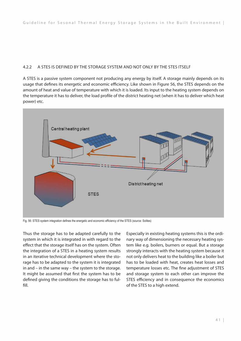
4.2.2 A STES IS DEFINED BY THE STORAGE SYSTEM AND NOT ONLY BY THE STES ITSELF
A STES is a passive system component not producing any energy by itself. A storage mainly depends on its usage that defines its energetic and economic efficiency. Like shown in Figure 56, the STES depends on the amount of heat and value of temperature with which it is loaded. Its input to the heating system depends on the temperature it has to deliver, the load profile of the district heating net (when it has to deliver which heat power) etc.
Fig. 56: STES system integration defines the energetic and economic efficiency of the STES (source: Solites)
Thus the storage has to be adapted carefully to the system in which it is integrated in with regard to the effect that the storage itself has on the system. Often the integration of a STES in a heating system results in an iterative technical development where the sto-rage has to be adapted to the system it is integrated in and – in the same way – the system to the storage. It might be assumed that first the system has to be defined giving the conditions the storage has to ful-fill.
Especially in existing heating systems this is the ordi-nary way of dimensioning the necessary heating sys-tem like e.g. boilers, burners or equal. But a storage strongly interacts with the heating system because it not only delivers heat to the building like a boiler but has to be loaded with heat, creates heat losses and temperature losses etc. The fine adjustment of STES and storage system to each other can improve the STES efficiency and in consequence the economics of the STES to a high extend.
4 1 |
G u i d e l i n e f o r S e s o n a l T h e r m a l E n e r g y S t o r a g e S y s t e m s i n t h e B u i l t E n v i r o n m e n t |

4.2.3 A STES NEEDS DIMENSIONING BY SYSTEM SIMULATION
Based on the necessity of optimizing the STES to the system it is integrated in and vice versa as it might be obvious that only transient system simulation taking into account the variation of heat flux, temperatures, thermal system behavior, control strategy etc. can lead to a sophisticated system layout.There is no technical standard or equal available that enables the technical consultant to dimension a STES “over the thumb”. For first pre-dimensioning first calculation programs are available (e.g. check www.solar-district-heating.eu). But for detailed technical dimensioning only the described transient system simulation enables to regard the important para-meters of the comprehensive system that interact with the STES as shown in Fig. 56. For the STES alrea-dy realized it is shown that even regarding only the most influencing parameters the task is to optimize a multi-dimension parameters field of several tens of parameters that depend on each other. Since some years, pilot plants with STES went through a detailed system simulation with easily over one thousand pa-rameter variations that were regarded in the simula-tion program. Thus simulating a STES system takes months and not only weeks. One of the most evalua-ted simulation programs for that purpose is TRNSYS.
4.2.4 THE DIMENSIONING CAN ONLY BE AS ACCURATE AS THE AVAILABLE DATA
When doing simulations for some months and opti-mizing a lot of depended parameters one might lose track of the input data on which all simulations base on. But these input data can mainly influence the si-mulation outcome and the deviation of parameters. Especially in retrofitting applications it is an advan-tage that the heating system, the STES has to be optimized to, is already known. Best benefit can be obtained if the existing system is monitored in detail concerning load profiles (heat power and amounts), temperature levels of supply and return, ambient temperature, solar irradiation etc. in transient data that allow simulation in short time steps. Experiences show that an appropriate time step for monitoring data is data for every 10 min to every hour over one typical year of operation.
4.2.5 A STES CONCERNS A LOT OF WORK SECTIONS
While typical storages for heating centrals like steel tank buffer storages of small volumes mostly concern only the consultant and the installer of the heating system, the situation changes enormously when in-tegrating a STES. Regarding the previous chapters it is obvious that the energetic and economic efficiency of a STES is affected also by the results of the ener-getic retrofitting of the connected buildings, of the operation strategy of the district heating net if exis-ting, of the capability of the construction engineers that are involved in the project concerning STES, of the kind the project manager can adjust all interfaces between the work sections etc.In the majority of cases the STES is to be realized out-side of a building integrated into the underground, partly buried or equal. Due to the thermal and static loads a STES expose to the underground it is impor-tant that the underground is checked for usability at an early stage. A geological survey can clear the pos-sibilities for STES at the building site.
4.2.6A STES HAS TO BE INTEGRATED INTO THE PROJECT DEVELOPMENT BY THE BEGINNING
As stated in the chapters before, a STES in-teracts with a lot of different subsystems and work sections and, even more important, de-pends on these influences regarding its own energetic and economic efficiency. Thus an overall efficient STES system integration only can be reached when STES prerequisites and interactions are regarded and well thought over the whole project development, starting from the beginning!
4.2.7BUILDING PERMITS/PLANNING PERMISSION
In order to construct a thermal energy store, a building permit may be required, depending on the building laws of each state.A preliminary inquiry at the competent buil-ding authority is recommended in order to cla-rify whether a building permit is necessary.
| 4 2
| G u i d e l i n e f o r S e s o n a l T h e r m a l E n e r g y S t o r a g e S y s t e m s i n t h e B u i l t E n v i r o n m e n t

4.3 FINANCING AND FUNDING
The planning and construction of seasonal thermal energy stores and other components for the use of re-newable energy – such as district heating networks, solar collectors, etc. – are eligible for funding through various national or EU-programmes under certain circumstances.
4.3.1 COSTSSeasonal thermal energy stores already established generally originated within the context of pilot or research projects. They did indeed support the con-struction of the thermal energy store, but also im-posed conditions – such as innovative design, solar thermal charging or something else.
Fig. 57: Specific costs of seasonal thermal energy storage systems (details do not include planning costs and VAT, source: Solites) TTES: Tank Thermal Energy StoragePTES: Pit Thermal Energy Storage
BTES: Borehole Thermal Energy StorageATES: Aquifer Thermal Energy Storage
DK: DenmarkHLB: High performance concrete (HPC)
GfK: Fibre-reinforced plastic (FRP)
The construction costs of the seasonal thermal energy stores already realised were scientifically evaluated and are shown in the diagram above. This illustrates the fundamental cost trends and differences for each indivi-dual type of thermal energy store by quoting the store size in cubic metres of water equivalent. Construction costs vary depending on project constraints. It is assumed that the implementation costs of seasonal storage facilities will fall if these stores are repeatedly built.
4 3 |
G u i d e l i n e f o r S e s o n a l T h e r m a l E n e r g y S t o r a g e S y s t e m s i n t h e B u i l t E n v i r o n m e n t |

4.4 TECHNICAL PLANNING REQUIREMENTS
The following technical factors have to be considered when planning seasonal thermal energy stores:
HYDROGEOLOGYWhether and what type of store can be established at a specific location largely depends on the hydrogeo-logical conditions at the respective site.
STORAGE TYPESelection of the appropriate store type according to hydrogeological conditions, system-side requi-rements (temperature levels, heat capacities), local conditions and cost-effectiveness.
SIZE OF STORESeasonal thermal energy storage only becomes ef-ficient from an energy and economic point of view as of a certain minimum size of about 1,000 m³ (water equivalent). For thermal energy stores that are not operated on a purely seasonal basis, but buffer the heat for weeks or a few months or can be used multi-functionally, smaller sizes may also be of interest.
DESIGNSuitable wall and insulation systems have to with-stand high thermal loads, possibly coupled with hu-midity and pressure loads. It is recommended that the structures are able to withstand any technical hazards (e.g. the possibility of drying out of the heat insulation if it should be penetrated by moisture).
CHARGING AND DISCHARGINGWith tank and pit heat stores, charging and dischar-ging has an effect on thermal stratification, the trans-ferable heat output and possible operating modes of the store (e.g. simultaneous loading and unloading, etc.).
HEAT CAPACITYThe heat supply may require high thermal capaci-ty when the store is being charged and discharged. Some types of stores, such as borehole thermal ener-gy stores, cannot provide high thermal capacities. This may necessitate additional buffer stores.
TEMPERATURE LEVELThe usable temperature differences between the ma-ximum charging and discharging of the store define (besides the specific heat capacity of the storage me-dium) the required size of the storage volume. The use of a heat pump when discharging the store can increase the usable temperature difference.
SYSTEM INTEGRATIONThe integration of the store in the whole system with regard to hydraulics and system control engineering defines the possible modes of operation, the effici-ency of the store and thus its cost effectiveness. „In-tegrated planning“ to optimise system integration is generally recommended.
APPROVALThe cost of a building and water permit depends greatly on the selected storage type and location. For building permits for tank and pit thermal energy stores, the site of the building area and the allowable height of the structure above the surrounding terrain are decisively relevant. With regard to underground heat storage, its location in water protection zones, the depth of the rock layers used and the thermal in-fluence of the surrounding soil may also need to be considered.
OPERATION AND MAINTENANCEThe costs of operating and maintaining thermal ener-gy stores are usually very low due to the seclusion of the systems. In aquifer thermal energy stores, conti-nuous water treatment during operation may be ne-cessary to avoid any scaling.After commissioning, a measuring and optimisation time of at least one year can maximize the benefits of store integration.
INTEGRATION IN EXISTING BUILDINGSIt has to be taken into consideration if the sesonal thermal energy storage system has to be implemen-ted into an existing building structure. If so, the requi-rements e.g. for space, geological conditions, use of several system components and layout of the whole system can differ from the system prerequisites and specifications needed for a sesonal thermal energy storage system implemented in a new site develop-ment.
| 4 4
| G u i d e l i n e f o r S e s o n a l T h e r m a l E n e r g y S t o r a g e S y s t e m s i n t h e B u i l t E n v i r o n m e n t

4.4.1 A/V RATIOBesides numerous other requirements, a certain mi-nimum size is an important condition for seasonal thermal storage that makes technical and economic sense.
The diagram shows the surface area to volume ratio (A/V) – which governs the thermal losses of a stores – for cylindrical containers of 1 to 10,000 m³ with a height-to-diameter ratio (H/D) of 1. The heat losses are proportional to the surface area, i.e. large volu-mes display significantly better efficiency due to bet-ter (i.e. smaller) A/V ratios, irrespective of the thick-ness of the thermal insulation.Furthermore, the thermal losses over a period of 6 months are displayed on the y-axis. Mean values gre-ater than 1 mean that more heat is lost in this period than the maximum that can be stored there.Only with stores with a volume larger than 1,000 m³ can seasonal thermal energy storage be achieved with moderate insulation thickness.
Fig. 58: Volumetric heat losses (A/V ratio) (source:solites)
The interdependence of heat loss and store size is even greater with underground heat storage systems (borehole and aquifer thermal energy stores) due to the partial or complete lack of insulation.
4 5 |
G u i d e l i n e f o r S e s o n a l T h e r m a l E n e r g y S t o r a g e S y s t e m s i n t h e B u i l t E n v i r o n m e n t |

4.4.2 BUILDING PHYSICSHigh demands are made on materials and compo-nent constructions of the thermal energy store, resul-ting primarily from the usually coupled requirement of high temperature stress and constant contact with moisture. The materials and structures used must also be guaranteed to function for 30 to 50 years.
Inside the store, water temperatures are between about 10-95° C. Thermal insulation is, therefore, in-tended to protect the thermal energy store against excessive thermal losses. For this purpose, they must be adequately dimensioned and permanently pro-tected from humidity. In unsuitable structures, mois-ture may penetrate – either from the inside through the diffusion processes described above, or from the outside through moist soil or surface water. In order to remove incipient wetness or moisture that has pe-netrated through cracks, a construction that allows diffusion outwards is necessary. This has to work per-manently even when in damp ground.
Fig. 59: Wall construction of a long-term thermal energy store (source: solites)
What you see in the figure below is the wall structure of a concrete vessel. The inner steel liner firstly en-sures the watertightness of the vessel, and second-ly, it serves as a vapour barrier to prevent the water vapour transport driven by the partial pressure from the inside outwards.
The following example is intended to illustrate the complexity:
| 4 6
| G u i d e l i n e f o r S e s o n a l T h e r m a l E n e r g y S t o r a g e S y s t e m s i n t h e B u i l t E n v i r o n m e n t

4.4.3 WATER PROTECTION
DRINKING WATER PROTECTIONThe most important aspect with the approval of a long-term thermal energy store is compliance with the laws and regulations for drinking water protec-tion.
TANK THERMAL ENERGY STORESTanks and pit heat storage units are relatively unprob-lematic when it comes to obtaining a permit because no water exchange takes place with the environment and these stores are, as a rule, so well insulated that, despite high operating temperatures, no significant impact on the adjacent ground is exerted.
BOREHOLE THERMAL ENERGY STORESIn a borehole thermal energy store, a geological and hydrogeological report providing information about the occurrence and flow conditions of the various water layers may be required for approval. Since de-tailed studies are required for the planning of the heat store in any case, this generally does not mean any significant additional effort. Furthermore, de-tailed calculations on the long-term warming of the surrounding ground should be submitted.
AQUIFER THERMAL ENERGY STORESThe use of an aquifer to store heat through direct water exchange naturally represents the greatest in-fluence on the subsoil and often entails a complica-ted authorisation procedure. In particular, a safe and permanent separation of the groundwater horizons used for heat storage from other layers that conduct water must be ensured. Furthermore, chemical and biological analyses of the groundwater currently available should be carried out in order to be able to make predictions about possible changes caused by the temperature increase.
CONSTRUCTION PERIOD AND CLOSUREBesides observing the above points mainly concer-ning the operation of the thermal energy store, any damage to the environment during construction or after closure of the system must also be taken into account. After the possible closure of a storage facili-ty, proper disposal is frequently required. This means that with all kinds of stores for which boreholes were drilled, it must be ensured that the pipes are filled in with well-sealing material. Likewise, only safe materi-als may be introduced into the soil.
APPROVAL PROCESSAt present, no universal approval procedures exist. Due to the individual circumstances of a long-term thermal energy store, it makes sense to contact the competent authorities early on and to discuss with them the necessary application and approval proce-dures.
For all types of stores, especially with regard to underground thermal energy stores (aquifer and borehole thermal energy stores), a preliminary hydrogeological investigation of the storage site is essential. What needs to be addressed, among other things, are the layer sequence, the position and slope of the water table, the hydraulic permeability of the subsoil, and the current speed and direction of groundwater. Furthermore, a water authorization procedure must be initiated at an early stage.The geological requirements of the storage site are listed according to the four storage technologies below.
INFLUENCE ON STORE SIZEWhen calculating storage volumes, geology plays an important role – particularly with underground ther-mal energy stores. In the case of borehole and aquifer thermal energy stores, the soil is the storage material. Depending on the properties of the activated layers of rock, the heat...• can be stored at different speeds or for different
lengths of time• can radiate heat to different distances into the sur-
rounding soil and• spread in different vertical and horizontal direc-
tions.This results in a complex distribution of heat in the rock, which varies according to the specific rock pro-perties and the thickness of the layers.The heat capacity of the geology also influences the storage properties of tank thermal energy stores, but to a much lesser extent. This is due to the construc-tion of the store structure.
4 7 |
G u i d e l i n e f o r S e s o n a l T h e r m a l E n e r g y S t o r a g e S y s t e m s i n t h e B u i l t E n v i r o n m e n t |

TANK THERMAL ENERGY STORES• Stable ground condition• Soil class II-III• At least 2 m above the groundwater horizon; 5-15 m depth
PIT THERMAL ENERGY STORES• Stable ground condition• Soil class II-III• At least 2 m above the groundwater horizon• A depth of 5 to 15 m
BOREHOLE THERMAL ENERGY STORES• Drillable ground• Soil class I-III and …• Either groundwater, low permeability (kf <10-10 m/s) and flow
rate (<1m/a)• Or NO groundwater, then high permeability also possible • 30-100 m deep
AQUIFER THERMAL ENERGY STORES• Aquifer with high porosity• Groundwater and high permeability (kf> 10-4 m/s) necessary• Low flow rate of groundwater• With an impermeable layer at the top and bottom• 20 – 50 m of Aquifer height
4.4.4 GEOLOGY
Important conditions and characteristics of the particular thermal energy store types that have to be taken into consideration:
| 4 8
| G u i d e l i n e f o r S e s o n a l T h e r m a l E n e r g y S t o r a g e S y s t e m s i n t h e B u i l t E n v i r o n m e n t

4.4.5 BUILDING CONSTRUCTION
Important key points that must be observed during the construction of the various thermal energy stores...
TANK THERMAL ENERGY STORES
STORE CONSTRUCTION• Cast-in-place concrete vessels or prestressed pre-
cast construction• possibly under internal pressure• Floor, wall and roof insulated
SEALING• Stainless or black sheet steel, possibly pre-moun-
ted on prefabricated parts and welded
HEAT INSULATION• Floor: foam glass gravel• Wall and roof: expanded glass granulate in memb-
rane formwork or equal
PROTECTION OF HEAT INSULATION• A „wall insulation system“ that is open to vapour
diffusion, able to withstand technical hazards
CHARGING/DISCHARGING• Stratification system
BOREHOLE THERMAL ENERGY STORES
STORE CONSTRUCTION• Double U-pipe borehole heat exchangers (heat-
resistant, pressure-resistant) in a circular layout• Concentrically expandable
HEAT INSULATION• Foam glass gravel• Shells (DK)
PROTECTION OF HEAT INSULATION• A sealant foil that is open to vapour diffusion
HYDRAULIC CONNECTION• Minimised connections (welding joints or com-
pression connectors)
PIT THERMAL ENERGY STORES
STORE CONSTRUCTION• Water-filled pit with a floating or cantilevered roof
or one resting on a gravel filling
SEALING• Aluminium-plastic composite or simple plastic
sheet, welded
HEAT INSULATION• Expanded glass granulate in membrane formwork
or equal
PROTECTION OF HEAT INSULATION• Vacuum control of the sealing web, hazard-safe
„wall insulation system“
CHARGING/DISCHARGING• Stratification system with charging cups• indirect charging and discharging through coils
AQUIFER THERMAL ENERGY STORES
STORE CONSTRUCTION• Two or more wells with winding wire filter• Use of highly corrosion-resistant materials in the
storage circuit• Prevent entry of oxygen
HEAT INSULATION• None
WATER TREATMENT• Depends on hydrochemistry• Regular water sampling
4 9 |
G u i d e l i n e f o r S e s o n a l T h e r m a l E n e r g y S t o r a g e S y s t e m s i n t h e B u i l t E n v i r o n m e n t |

5. OPERATION
The proper operation of a Sesonal Thermal Energy Store (STES) always should be checked and follo-wed by detailed monitoring. Therefore a monito-ring equipment has to be designed and installed during the building process of the STES. It has to be considered that a STES needs typically one year of operation to reach all planned system condi-tions. If the first year of operation offers some un-balanced system behavior due to a not optimized control strategy or equal, it is obvious that it might take two years of operation or even more until a STES could reach all system conditions for it was designed for. The monitoring of a STES should focus on the fol-lowing three main observations:
• Thermodynamic behavior of the STES itself, e.g. by checking the temperature development in the STES
• Interaction of the STES with the system e.g. by checking the charging and discharging of energies and the yearly energy balance.
• Interaction of the STES with the surrounding underground.
To illustrate the operation of a STES and the possi-ble monitoring data, the example of the pit ther-mal energy storage of the Sunstore 4-project1 is chosen and shown in the following.
(1) SUNSTORE 4 - DELIVERABLE D 4.4Project: SUNSTORE 4 - Innovative, multi-applicable and cost efficient hybrid solar (55%) and biomass energy (45%) large scale (district) heating system with long term heat storage and organic Rankine cycle electricity production; Grant agreement No°: ENER/FP7/249800/"SUNSTORE 4; FP7 - Theme 5 – Energy – Collaborative Project; European Commission – DG TREN
| 5 0
| G u i d e l i n e f o r S e s o n a l T h e r m a l E n e r g y S t o r a g e S y s t e m s i n t h e B u i l t E n v i r o n m e n t

Figure 60 shows the heat balance of the 75 000 m³ PTES for 2013. The presented internal ener-gy change is calculated based on the values of 33 temperature sensors distributed in different heights inside the storage volume.With the numbers of the heat balance and the measured maximum and minimum temperatures inside the storage in 2013 (77 °C and 13 °C respec-tively) the following characteristic figures can be identified:
• Storage efficiency: 65 %• No. of storage cycles: 0.8• Heat capacity: 5 500 MWh
Fig. 60: Sunstore 4 PTES energy flow diagram for 2013 (source solites)
Figure 61 illustrates the monthly heat balance of the PTES. The main charging of the storage takes place du-ring the summer months, discharging in the winter pe-riod. Besides some single months in spring and autumn, where almost the same amount of heat is charged and discharged, a clearly seasonal operation of the storage can be seen. This was already indicated above by the sto-rage cycle number of 0.8 for 2013.
Fig. 61: Sunstore 4 PTES monthly energy balance (no complete data available until February 2013 due to finalisation of component installations and data acquisition system; data gap in April 2014) (source: solites)
5 1 |
G u i d e l i n e f o r S e s o n a l T h e r m a l E n e r g y S t o r a g e S y s t e m s i n t h e B u i l t E n v i r o n m e n t |
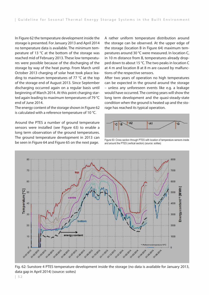
Around the PTES a number of ground temperature sensors were installed (see Figure 63) to enable a long term observation of the ground temperatures. The ground temperature development in 2013 can be seen in Figure 64 and Figure 65 on the next page.
Figure 63: Cross section through PTES with location of temperature sensors inside and around the PTES (vertical section) (source: solites)
In Figure 62 the temperature development inside the storage is presented. For January 2013 and April 2014 no temperature data is available. The minimum tem-perature of 13 °C at the bottom of the storage was reached mid of February 2013. These low temperatu-res were possible because of the discharging of the storage by way of the heat pump. From March until October 2013 charging of solar heat took place lea-ding to maximum temperatures of 77 °C at the top of the storage end of August 2013. Since September discharging occurred again on a regular basis until beginning of March 2014. At this point charging star-ted again leading to maximum temperatures of 79 °C end of June 2014.The energy content of the storage shown in Figure 62 is calculated with a reference temperature of 10 °C.
Fig. 62: Sunstore 4 PTES temperature development inside the storage (no data is available for January 2013, data gap in April 2014) (source: soites)
A rather uniform temperature distribution around the storage can be observed. At the upper edge of the storage (location B in Figure 64) maximum tem-peratures around 30 °C were measured. In location C, in 10 m distance from B, temperatures already drop-ped down to about 15 °C. The two peaks in location C at 4 m and location B at 8 m are caused by malfunc-tions of the respective sensors.After two years of operation no high temperatures can be expected in the ground around the storage – unless any unforeseen events like e.g. a leakage would have occurred. The coming years will show the long term development and the quasi-steady-state condition when the ground is heated up and the sto-rage has reached its typical operation.
| 5 2
| G u i d e l i n e f o r S e s o n a l T h e r m a l E n e r g y S t o r a g e S y s t e m s i n t h e B u i l t E n v i r o n m e n t

Figure 64: Temperature development inside and around the S4 PTES in 2013 (A1: inside the storage volume, C+B: west of the storage, G: east of the storage, see also Figure 63) (source: solites)
Figure 65: Temperature development inside and around the S4 PTES in 2013 (A1: inside the storage volume, D: south of the storage, F: north of the storage, see also Figure 63) (source: solites)
5 3 |
G u i d e l i n e f o r S e s o n a l T h e r m a l E n e r g y S t o r a g e S y s t e m s i n t h e B u i l t E n v i r o n m e n t |

Glossary
Key word Explanation
absorber Component with coated surface (usually in a collector) that absorbs solar radiation, converts it into heat and conducts it to a heat transfer medium
absorber area Total solar effective absorber surface in a collector (field).
initial moisture Moisture that enters into the construction during the building phase (e.g. rain, dew, etc.)
initial investment The necessary amount of heat to heat a store in the commissioning phase from the filling temperature to the minimum operating temperature (about 40° C)
aperture area The surface of a solar collector through which the solar radiation enters (proportion of glass) less than the collector surface (frame size)
aquifer (geol. definition) Geological formation with naturally occurring confined underground layer of water
STES ATES PTES BTES TTES HTES
Seasonal Thermal Energy Storage Aquifer Thermal Energy Storage Pit Thermal Energy Storage Borehole Thermal Energy Storage Thank Thermal Energy Storage Hot Thermal Energy Storage
charging cups Specific charging and discharging system, which greatly enlarges the diameter of the pipes to reduce the flow rate at the charging and discharging points in the store (> a shallow "cup" forms)
bentonite Rock mixture of various clay materials with increased hygroscopicity and swellability
Berlin type pit lining Pile wall, secures the pit during the construction phase and prevents soil slippage.
expanded glass granulate Highly insulating insulation material made from recycled glass shredded recycled glass is inflated in the oven; (chemically resistant, pressure-resistant, pourable, pneumatically conveyable)
sheet metal coil Sheet metal that has been rolled thin and is wound on so-called "coils" for transportation coil: technical term for a strip steel coil;
soil class Soil and rock classes
gross heat yield Heat yield (e.g. a collector circuit without deduction of line losses)
coil Technical term for strip steel coil
Concerto European Union initiative on smart energy solutions for cities and towns http://concerto.eu/concerto/
CoP Coefficient of performance [(electric power supplied)/(useful heat output)]
steady state State of the thermal energy store after the initial charging phase and initial heating of the surrounding soil
Glossary
| 5 4
| G u i d e l i n e f o r S e s o n a l T h e r m a l E n e r g y S t o r a g e S y s t e m s i n t h e B u i l t E n v i r o n m e n t

settling time Initial charging phase of the seasonal thermal energy store including initial heating of the surrounding soil
ground heat collector Heat exchangers that are installed horizontally or diagonally in the upper 5 metres of the subsurface and which extract heat energy from the subsurface and inject heat into it
EU European Union
Exergy Part of the total energy that can be converted into work once the system has been brought into equilibrium Exergy thus has a high level of usability
R&E programme Research and development programme
FEM Finite element method Calculation program that subdivides complex geometries into many smaller parts (finite elements)
total heat demand Sum of all heat requirements mostly domestic hot water and space heating
GRP Glass-fibre reinforced plastic (GRP) Lightweight and durable construction material made of glass fibres bonded with synthetic resins; also known as GFK (from German: glasfaserverstärkter Kunststoff)
global radiation Total incoming solar radiation on the surface (direct and diffuse) as a local constant dependent on the weather, cloud cover, altitude above sea level and distance from the equator; (in Germany every year usually 900-1100 kWh/m² x a)
glycol A dihydric alcohol (is added to the water in the collector circuit as an antifreeze)
GL Abbr.: ground level
degree day Heating degree day (dimension of the thermal energy demand of a building during the heating season – a location-dependent parameter reflecting local weather) [K x d]
foundation Base of a building that takes the loads.
able to withstand technical hazards
Not adversely affected by disasters (= major events of damage or loss)
HPC Abbr.: high performance concrete
hydraulic Hydraulics = the flow behaviour of fluids for energy transfer
hydraulic separator An element in water pipe systems for the hydraulic decoupling of two circuits to compensate for fluctuations in pressure and flow
hydrochemistry Synonym: water chemistry This is a part of hydrogeology and describes the substances in water and their responsiveness
5 5 |
G u i d e l i n e f o r S e s o n a l T h e r m a l E n e r g y S t o r a g e S y s t e m s i n t h e B u i l t E n v i r o n m e n t |
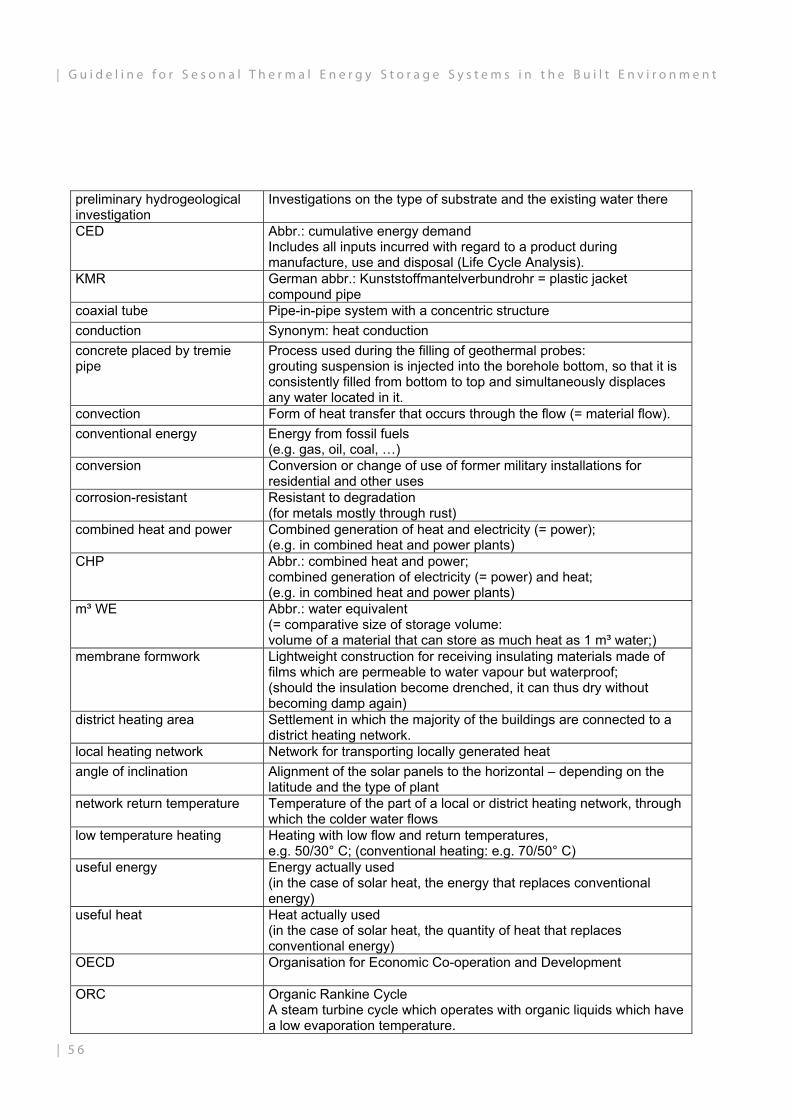
preliminary hydrogeological investigation
Investigations on the type of substrate and the existing water there
CED Abbr.: cumulative energy demand Includes all inputs incurred with regard to a product during manufacture, use and disposal (Life Cycle Analysis).
KMR German abbr.: Kunststoffmantelverbundrohr = plastic jacket compound pipe
coaxial tube Pipe-in-pipe system with a concentric structure conduction Synonym: heat conduction concrete placed by tremie pipe
Process used during the filling of geothermal probes: grouting suspension is injected into the borehole bottom, so that it is consistently filled from bottom to top and simultaneously displaces any water located in it.
convection Form of heat transfer that occurs through the flow (= material flow). conventional energy Energy from fossil fuels
(e.g. gas, oil, coal, …) conversion Conversion or change of use of former military installations for
residential and other uses corrosion-resistant Resistant to degradation
(for metals mostly through rust) combined heat and power Combined generation of heat and electricity (= power);
(e.g. in combined heat and power plants) CHP Abbr.: combined heat and power;
combined generation of electricity (= power) and heat; (e.g. in combined heat and power plants)
m³ WE Abbr.: water equivalent (= comparative size of storage volume: volume of a material that can store as much heat as 1 m³ water;)
membrane formwork Lightweight construction for receiving insulating materials made of films which are permeable to water vapour but waterproof; (should the insulation become drenched, it can thus dry without becoming damp again)
district heating area Settlement in which the majority of the buildings are connected to a district heating network.
local heating network Network for transporting locally generated heat angle of inclination Alignment of the solar panels to the horizontal – depending on the
latitude and the type of plant network return temperature Temperature of the part of a local or district heating network, through
which the colder water flows low temperature heating Heating with low flow and return temperatures,
e.g. 50/30° C; (conventional heating: e.g. 70/50° C) useful energy Energy actually used
(in the case of solar heat, the energy that replaces conventional energy)
useful heat Heat actually used (in the case of solar heat, the quantity of heat that replaces conventional energy)
OECD Organisation for Economic Co-operation and Development
ORC Organic Rankine Cycle A steam turbine cycle which operates with organic liquids which have a low evaporation temperature.
| 5 6
| G u i d e l i n e f o r S e s o n a l T h e r m a l E n e r g y S t o r a g e S y s t e m s i n t h e B u i l t E n v i r o n m e n t

cast-in-place concrete Concrete that is poured into formwork and sets on site cast-in-place construction method
Method of construction using cast-in-place concrete (= concrete poured into formwork on site where it then sets)
partial pressure gradient Partial pressure is the pressure which may be associated with a particular gas in a gas mixture; if there are different partial pressures within a system (pressure differential between the gases), they are always striving to find a balance
PCM Phase Change Material PE-RT Abbr.: polyethylene of raised temperature
non-cross-linked polyethylene of elevated temperature resistance PEX Cross-linked polyethylene
(pipes made from this can be operated in continuous operation with up to 6 bar pressure and a fluid temperature of up to 90° C)
PE-X Cross-linked polyethylene (pipes made from this can be operated in continuous operation with up to 6 bar pressure and a fluid temperature of up to 90° C)
PIMES Play it more efficient, Sam A CONCERTO project: towns on the way to the thermal and electrical efficiency of buildings and districts, based on MICROGRIDS
plane Synonym: level, flat polybutene A synthetic material press fitting A permanently connecting piece of pipelines that is pressed so that it
is form-fitting; press fittings Permanently connecting pieces of pipelines that are pressed so that
they are form-fitting primary circuit The heat-supplying circuit on one side of the heat exchanger. primary side The heat-supplying side in the circuit of a heat exchanger. RHC-TP Renewable Heating & Cooling - European Technology Platform;
pipe coils Plastic pipes laid in loops that are installed in, for example, seasonal
thermal energy stores for indirect heat transfer return flow Part of the heat circuit that carries the colder water foam glass gravel Insulation made from recycled glass or natural materials (sand,
dolomite, lime) during combustion with carbon the ground waste glass "foams", forming heat insulating bubbles (dimensionally stable, water-resistant, resistant to high pressure)
leg lengths The parts of pipelines of a geothermal probe are called "legs" This is measured from the lowest point to the top end of the pipeline
stratification device Component of a water--filled thermal energy store enables charging at different levels, without the temperature layers mixing with each other
auger drilling This is carried out by vibration-free boring of a hollow continuous flight auger into the ground
secondary circuit Circuit on one side of the heat exchanger that the heat is transferred to
secondary side The side in the circulation of a heat exchanger that the heat is transferred to
SHC Solar Heating & Cooling Programme of the IEA
5 7 |
G u i d e l i n e f o r S e s o n a l T h e r m a l E n e r g y S t o r a g e S y s t e m s i n t h e B u i l t E n v i r o n m e n t |

costs of solar-generated useful heat
The costs of heat gained from solar energy in the system being considered
solar heat Heat generated by solar energy [Wh, kWh, Wh/a, kWh/a]
solar fraction The proportion of the energy used, which is covered by solar energy solar grid Supply network from the solar component (e.g., collector) to the
heating plant solar season The sunnier months with a high level of solar radiation
(in Europe: May to September) solar transfer station Assembly with a heat exchanger and control technology for
transferring solar heat, e.g. to the heat store solar heat Heat generated by solar energy
[Wh, kWh, Wh/a, kWh/a] probe leg Individual pipes of a U-shaped geothermal probe store charging system Domestic hot water system
the heating of the water in a drinking water reservoir opposite: continuous flow heating systems
cups specific charging and discharging system, which greatly enlarges the diameter of the pipes to reduce the flow rate at the charging and discharging points in the store (> a shallow "cup" forms)
TES Thermal Energy Storage
inertia Reaction rate of a thermal energy store (e.g.: tank thermal energy stores can be more quickly charged and discharged than borehole thermal energy storage systems, since heat transport in water takes place faster than in the subsurface)
domestic hot water Domestic hot water of drinking water quality TRNSYS TRaNsient SYstem Simulation Programme
underground thermal energy store
Storage unit that stores the heat in the subsoil i.e. aquifer or borehole thermal energy storage
UTES Underground Thermal Energy Storage
U-value Heat transfer coefficient This insulation value designates the heat transfer through a building material or construction [W/m2*K]
lost formwork Formwork that is left in place and remains in the part and is, therefore, "lost"
circuitry Connection of pipelines, aggregates, valves, etc. to a system through which liquid flows
volume flow Quantities of water or water-glycol mixture flowing through the system [m3/h, l/s]
flow Part of the heating circuit, which conducts the heated water wall insulation system Complete system necessary for the lasting function of the insulation
of a seasonal thermal energy store. (among others PE films, insulation material, gravel beds, etc.)
heat transfer coefficient U-value this insulation value designates the heat transfer through a building material or construction [W/m2 x K]
overall heat transfer coefficient
U-value; this insulation value designates the heat transfer through a building material or construction [W/m2 x K]
heat capacity Material property that indicates how much heat a material can store [J/(kg x K)]
| 5 8
| G u i d e l i n e f o r S e s o n a l T h e r m a l E n e r g y S t o r a g e S y s t e m s i n t h e B u i l t E n v i r o n m e n t

heat output The fraction of power produced during energy conversion processes that can be used as heat;
thermal conductivity Material constant, which indicates how well or badly a material conducts heat; [W/(m*K)]
quantity of heat Quantitative description of heat; [kWh]
heat storage ability Material property that indicates how much heat a material can store; [J/(kg x K)] DIN 4108
heat storage capacity Material property that indicates how much heat a material can store; [J/(kg x K)] DIN 4108
heat transfer medium Medium that transports heat in a system circuit (often water)
heat transfer station Interface between local heating network and installations in the home; direct or indirect heat transfer (by means of a heat exchanger) is possible;
water equivalent Comparative figure of storage volume: Volume of a material that can store as much heat as 1 m3 of water
water sampling Microbiological tests of water WHG Abbr.: Wasserhaushaltsgesetz – Water Resources Act;
contains provisions on the protection and use of surface water and groundwater, as well as on the development of waters, water planning and flood protection
wire wrapped screens Wire mesh in the fountain of an aquifer, which effectively and permanently prevents the ingress of fines from the aquifer
woven fibre fabrics Geotextile Source: http://ais.online.de
WI concrete Water-impermeable concrete
5 9 |
G u i d e l i n e f o r S e s o n a l T h e r m a l E n e r g y S t o r a g e S y s t e m s i n t h e B u i l t E n v i r o n m e n t |

| 6 0
| G u i d e l i n e f o r S e s o n a l T h e r m a l E n e r g y S t o r a g e S y s t e m s i n t h e B u i l t E n v i r o n m e n t

6 1 |
G u i d e l i n e f o r S e s o n a l T h e r m a l E n e r g y S t o r a g e S y s t e m s i n t h e B u i l t E n v i r o n m e n t |
This guideline is the outcome of the EU-FP7 project „EINSTEIN“ (Effective integration of seasonal thermal energy storage systems in existing buildings), grant agreement no. 284932.For additional information please check the other deliverables of the project and www.einstein-project.eu.
Disclaimer: The sole responsibility for the content of this publication lies with the authors. It does not necessarily reflect the opinion of the European Union.Neither the European Commission nor the authors are responsible for any use that may be made of the informa-tion contained therein.
IMPRINT:Authors and Editors:
Dipl.-Ing. Dirk Mangold
Dipl.-Ing. Thomas Schmidt
Antonia DohnaDipl.-Ing. Architecture
Daniel SpähB.A. Architecture

SolitesSteinbeis Research Institute for Solar and Sustainable Thermal Energy SystemsMeitnerstr. 8, 70563 Stuttgart, Germany
Tel.: +49 (0)711 673 2000-0, Fax.: +49 (0)711 673 2000-99Email: [email protected], Internet: www.solites.de
Enterprise within the Steinbeis network (www.steinbeis.de):
Zentrale/ Central Office: Steinbeis Innovation gGmbHHaus der Wirtschaft, Willi-Bleicher-Strasse 19, 70174 Stuttgart, GermanySitz der Gesellschaft/ Registered Office: Stuttgart, Registergericht/ Register Court: Stuttg-art HRB 720289Geschäftsführer/ Managing Director: Dipl.-Ing. (FH), M. Eng. Erik Burchardt
published: January 2016Copyright 2016 by Solites