for recurdyn (2003.5) - functionbay, inc. · pdf filehic displacement mm ... design...
TRANSCRIPT

1
Center of
Center of Innovative Design Optimization Technology
발표 순서
최적설계신기술
적용 예
Probabilistic Optimization (DFSS)

3Center of Innovative Design Optimization Technology
설계비용은 제품원가의 5%이지만
설계가 제품원가에 미치는 영향은 70%
70%20%
5%5%
5% PRODUCTDESIGN
50% MATERIAL
15% LABOR
30% OVERHEAD
COST(%)
INFL
UE
NC
E(%
)
설계의 중요성최적설계신기술
4Center of Innovative Design Optimization Technology
Durability Safety
Vehicle Dynamics NVH
설계요구의 다양성최적설계신기술

5Center of Innovative Design Optimization Technology
설계절차의 자동화
설계조건의 통합화 설계해의 최적화
제품원가 절감
제품성능 향상개발기간 단축
컴퓨팅기술의 발전 최적화기술의 발달다분야통합최적설계
(MDO) 기술
최적설계 신기술최적설계신기술
6Center of Innovative Design Optimization Technology
회전시의 소음
공진
와류
유동장
원심력
압력분포
유동해석 구조해석
소음해석
유동장 및압력분포
압력분포
변형
고유진동수
설계요구: •요구되는 유량과 정압을 발생
•효율최대화
•소음최소화
설계변수: 블레이드의 형상, 두께, 개수
자동차 COOLING FAN의 설계최적설계신기술

7Center of Innovative Design Optimization Technology
Time into design process
Conceptual Preliminary Detailed
Knowledge about design
Design Freedom
AerodynamicsStructuresPropulsionsControlsManufacturingSupportabilityCost
100%
Traditional Design Practice최적설계신기술
8Center of Innovative Design Optimization Technology
Cost
Time into design process
Conceptual Preliminary Detailed
Knowledge about design
Design Freedom
AerodynamicsStructuresPropulsionsControlsManufacturingSupportability
100%
Design Vision최적설계신기술
9Center of Innovative Design Optimization Technology
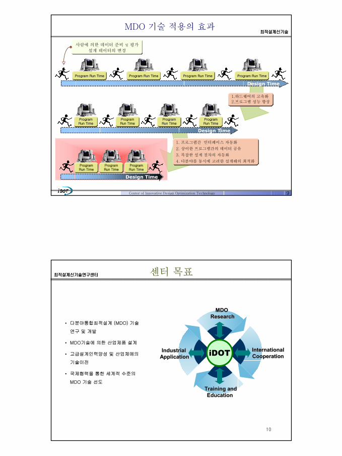
Design Time
1.하드웨어의 고속화
2.프로그램 성능 향상
1. 프로그램간 인터페이스 자동화
2. 상이한 프로그램간의 데이터 공유
3. 복잡한 설계 절차의 자동화
4. 다분야를 동시에 고려한 설계해의 최적화
Design Time
Design Time
Program Run Time
Program Run Time
Program Run TimeProgram Run Time
사람에 의한 데이터 준비 및 평가
설계 데이터의 변경
Program Run Time
Program Run Time
Program Run Time
Program Run Time
Program Run Time
Program Run Time
Program Run Time
MDO 기술 적용의 효과최적설계신기술
10
• 다분야통합최적설계 (MDO) 기술
연구 및 개발
• MDO기술에 의한 산업제품 설계
• 고급설계인력양성 및 산업체에의
기술이전
• 국제협력을 통한 세계적 수준의
MDO 기술 선도
MDO MDO ResearchResearch
Industrial Industrial ApplicationApplication
Training andTraining andEducation Education
iDOT InternationalInternationalCooperationCooperation
센터 목표최적설계신기술연구센터

11
총괄과제
1.최적화기술 개발(Optimization Technology)
2.기반구조 구축(Computing Infrastructure)
3.통합설계 구현(Integrated Design)
산업 제품
적용 기법
설계
관리 기법
최적화 문제
구성 기법
MDO
방법론근사 최적화
기법
전역 최적화
기법
MDOKernel
MDO 프레임웍
“The Ultimate Design Machine”
통합설계
모듈 분산
컴퓨팅
화모듈최적
DB
CAD
구조해석
유동해석
동역학해석
전자기장해석
사용자
연구과제의 구성 및 유기성최적설계신기술연구센터
12
제1총괄과제
최적화기술 개발
최 동 훈한양대학교
이 병 채한국과학기술원
임 오 강부산대학교
왕 세 명광주과학기술원
이 종 수연세대학교
이 태 희한양대학교
민 승 재한양대학교
제2총괄과제
기반구조 구축
정 재 일한양대학교
이 세 정서울시립대학교
이 재 호서울시립대학교
제3총괄과제
통합설계 구현
박 경 진한양대학교
이 동 호서울대학교
이 관 수한양대학교
하 성 규한양대학교
유 홍 희한양대학교
홍 은 지성공회대학교
김 태 권강남대학교
연구 집단최적설계신기술연구센터

13Center of Innovative Design Optimization Technology
TemplatesTemplates
User InputsUser Inputs
Library DataLibrary Data
VehicleDatabaseVehicle
Database
CrashworthinessLPM, DYNA3DCrashworthinessLPM, DYNA3D
External AerodynamicsGM Program
External AerodynamicsGM Program
Heat LoadGM ProgramHeat Load
GM Program
Occupant DynamicsCAL3D
Occupant DynamicsCAL3D
Suspension LoadsADAMS
Suspension LoadsADAMS
Other AnalysesOther Analyses
Elastic StructuresODYSSEY, NASTRAN
Elastic StructuresODYSSEY, NASTRAN
AutomaticModeler
Parameter
Model
DesignProgram
Automatic Modeler & Analyzers
GM의 경우 (1995년도)최적설계신기술
14Center of Innovative Design Optimization Technology
TemplatesTemplates
User InputsUser Inputs
Library DataLibrary Data
VehicleDatabaseVehicle
Database
CrashworthinessLPM, DYNA3DCrashworthinessLPM, DYNA3D
External AerodynamicsGM Program
External AerodynamicsGM Program
Solar LoadGM ProgramSolar Load
GM Program
Occupant DynamicsCAL3D
Occupant DynamicsCAL3D
Suspension LoadsADAMS
Suspension LoadsADAMS
Fuel EconomyGM Program
Fuel EconomyGM Program
Other AnalysesOther Analyses
Elastic StructuresODYSSEY, NASTRAN
Elastic StructuresODYSSEY, NASTRAN
ResultsDatabaseResults
Database MDO
Parametric
Modeler
Discipline
Modeler
Discipline A
nalysis &Sensitivity C
alculations
Integrated Vehicle Design Analysis : MDO
GM의 경우 (1998년도)최적설계신기술

StructuralAnalysis
(NASTRAN)
DesignRepresentation(Unigraphics)
AerodynamicsInterior
Roominess(Excel)
Fuel Economy
Database(MS Access)
Business(Excel)
MultidisciplinaryDesign
Summary ofResults(Excel)
Architecture Configuration & Parameterization
RockerCenterline
DesignedRocker Section
Exterior Width Shoulder Room Gauges, Areas, Section Sizes, Overall Width
Frontal Area
Bo
dy S
tru
ctu
re M
ass
Fuel Economy,Performance
Value ofRoominess
Net Income
What is an archietecture?
1. Common component shared by products2. Common manufacturing processes used
to build the products
MDO System for Vehicle Architectures on the early design phase in ‘GMGM’2002
15Center of Innovative Design Optimization Technology
최적설계신기술
16Center of Innovative Design Optimization Technology
Panther Program
Durability Safety
Vehicle Dynamics NVH
Simultaneous Analysis
Improve NVH responseswithout penalties on weight or vehicle handling performancewhile including durability and safety as side constraints
Ford Panther Program (1996년도)최적설계신기술

17Center of Innovative Design Optimization Technology
MDO기술을 이용하여 NVH, 차량동역학, 차체내구성, 차체안전성을 고려하여 동시해석 (Simultaneous Analysis)을 수행
Panther Program
초기 20-25%설계단계에서 제품가격의 60% 결정
CAE검증 후 시작품을 제작으로 설계기간 및 비용 절감
Experimental-based 개발시간의 10%로 Analysis-based 개발 수행
9,100만불의 엔지니어링 비용 절감
자동차 단종시까지 10억불의 자동차 유동비(variable cost) 절감
Ford 자동차의 경우 (1996년도)최적설계신기술
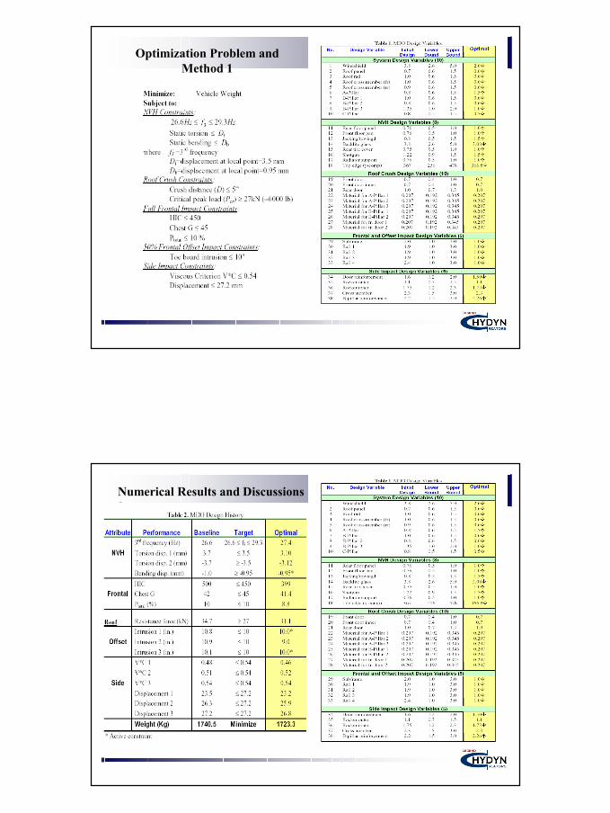
Minimize : Vehicle weight
Subject to :
– NVH Constraints
– Roof Crush Constraints
– Full frontal impact Constraints
– 50% frontal offset impact Constraints
– Side impact Constraints
b
t
DbendingStaticDtorsionStatic
HzfHz
≤≤≤≤ 3.296.26 3
( )( ) ( )lbkNPloadpeakCritical
DancedistCrush
cr 600027"5
≈≥≤
"10≤trusioninboardToe
%1045
450
≤≤
≤
totalPGChest
HIC
mmntDisplacemeCVCriterionViscous
2.2754.0*
≤≤
MSC.NasranGlobal Response SurfaceDOE : Optimul Latin Hyper Cube
RADIOSS codeMADYMO
MDO of Vehicle Structure in ‘FORDFORD’ 2002
Center of Innovative Design Optimization Technology
최적설계신기술
Optimization Problem and Method 1
Numerical Results and Discussions 2

Center of Innovative Design Optimization Technology
발표 순서
최적설계신기술
적용 예
Probabilistic Optimization (DFSS)
22Center of Innovative Design Optimization Technology
1
z' z y'
y
1t
2t3t
1SV
θ=2SV
BAR(362), ELAS1(507), QUAD4(2357), ROD(47), DAMP1(4), HEXA(344), CONM2(169), PENTA(92), TRIA3(616)
f) Rockerc) B Pillar
b) A Pillar
a) Front Roof Raile) Side Roof Rail
d) C Pillar
OPTIMIZERUsing TDQA
MSC/NASTRANINTERFACE
MSC/NASTRAN
DesignVariables
Analysis &DSA Data
Input File Output files
EXP-SECT Mode-TrackDesign variables
1st bendingfreq.
Hz
2nd bendingfreq.
1st torsionalfreq.
Frequency Constraints
Minimize Weight
Objective
Section Thicknesses (36)Section Shape Variables (112)
Intermediate Variables
Section Properties (A, I, J)Joint Stiffness (K)
차체구조 최적설계 (1)적용 예
23Center of Innovative Design Optimization Technology
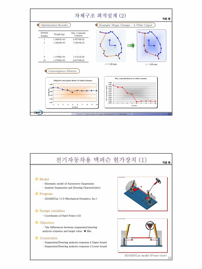
차체구조 최적설계 (2)적용 예
1.51321E-041.37998E+0396.03774E-051.37999E+0310
.
.
.
.
.
.
.
.
.
3.78819E-021.38829E+0324.30770E-021.38883E+031
Max. Constraint ViolationWeight (kg)
IterationNumber
Max. constraint history of vehicle structure
-0.0050.0000.0050.0100.0150.0200.0250.0300.0350.0400.0450.050
1 2 3 4 5 6 7 8 9 10
IterationM
ax. C
onst
rain
t Vio
latio
n
t = 1.80 mm t = 1.00 mm
x
y
x
y
Convergence History
Optimization Results Example Shape Change – A Pillar Upper
•Objective convergence history of vehicle structure
•1350
•1360
•1370
•1380
•1390
•1400
•1 •2 •3 •4 •5 •6 •7 •8 •9 •10
•Iteration
•Wei
ght (
kg)
24
전기자동차용 맥퍼슨 현가장치 (1)
Model
Program
Design variables
- Kinematic model of Automotive Suspension
- Analyze Suspension and Steering Characteristics
- ADAMS/Car 11.0 (Mechanical Dynamics, Inc.)
- Coordinates of Hard Points (15)
ADAMS/Car model (Front view)
Constraints
Objective
- The Differences between suspension/steering
analysis response and target value Min.
- Suspension/Steering analysis response ≤ Upper bound
- Suspension/Steering analysis response ≥ Lower bound
적용 예

25
전기자동차용 맥퍼슨 현가장치 (2)
Target
Initial
Wheel travel
Performance
Target
Initial
Wheel travel
Performance
Bound
Initial
Performance
Wheel travel
Bound
Initial
Performance
Wheel travel
Design requirements
Camber Angle
Toe Angle
Anti-Dive
Roll Center Height
Caster Angle
SuspensionCharacteristics
Performance Design variables
적용 예
26
전기자동차용 맥퍼슨 현가장치 (3)
WindowScripting
Host
ADAMS/Car
EMDIOS
실행명령
Performance
GUI를 통한실행명령
Designvariable
적용 예

27
전기자동차용 맥퍼슨 현가장치 (4)
Toe angle
-100 -50 0 50 100
-0.5
-0.4
-0.3
-0.2
-0.1
0.0
0.1
0.2
0.3
0.4
0.5
0.6 Lower Target Initial Upper FinalSQP
Wheel travel (mm)
Toe
angl
e (D
eg)
Caster angle
-100 -50 0 50 100
1.0
1.5
2.0
2.5
3.0
3.5
4.0 Lower Target Inital Upper FinalSQP
Wheel travel (mm)
Cas
ter a
ngle
(Deg
)
Anti-dive
-100 -50 0 50 100
0
5
10
15
20
25
30 Lower Target Initial Upper FinalSQP
Wheel travel (mm)
Ant
i-div
e (%
)
Roll center height
-100 -50 0 50 100-300
-200
-100
0
100
200
300
400 Lower Target Initial Upper FinalSQP
Wheel travel (mm)
Rol
l cen
ter h
eigh
t (m
m)
Camber angle
-100 -50 0 50 100
-3.0-2.5-2.0-1.5-1.0-0.50.00.51.01.52.02.53.03.54.04.5
Lower Target Initial Upper FinalSQP
Wheel travel (mm)
Cam
ber a
ngle
(Deg
)
적용 예
28
Design Requirements
Design Variables
Design Objective
•Wheel travels of six wheels (6)•Equal load sharing among six wheels in steady state (6)
•Track tension (1)•Initial charge pressures of the third and forth HSU’s (2)
•Side Constraints
•Initial charge pressures for the first, second, fifth, and sixth HSU’s (4)
•Static track tension (1)•Length of a gas chamber (1)•Preload on Beleville springs (1)•Inside radius of an orifice (1)•Flow rate at choking point (1)
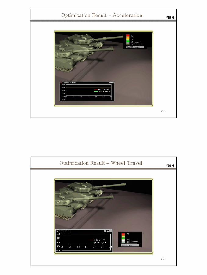
Minimize the maximum acceleration of the hull of a tracked vehicle when it runs over a semi-circular bump of 0.36m radius with a velocity of 40 km/h
Problem Formulation 적용 예
29
Optimization Result - Acceleration적용 예
30
Optimization Result – Wheel Travel적용 예

31Center of Innovative Design Optimization Technology
Inflow
Tubes
Y
S
P
Outflow
x
y
X
D2
Z
x
z
D1
(a) Top view
(b) Front view
Computational Domain
31.00 mm12.12 mm0.98 mm7.00 mm6.06 mm1.40 mm3.80 mm
X ( width of the channel )Y ( length of the channel )Z ( height of the channel )S ( pin spacing )P ( pin pitch )D1 ( pin diameter at z = Z )D2 ( pin diameter at z = 0 )
valuesParameters
Baseline geometry
Plate-Fin and Tube Heat Exchanger적용 예
32Center of Innovative Design Optimization Technology
Objective
- Minimize the pressure drop, - Maximize the overall heat transfer rate, Nu
p∆
Constraints and Side constraints
23S D X+ ≤2P D Y+ ≤
( )1/ 222
2 / 2D P S ≤ +
2D S≤2D P≤
1 2D D≤
0 10S≤ ≤0 12P≤ ≤
10 8D≤ ≤
20 8D≤ ≤
Side constraints [mm]Constraints
Y
Inflow
Outflow
y
x
S
P
D2
D1
Z
X
x
z
Layout of the heat exchanger
, , , , Design Variables
- Tube spacing (S), Tube pitching (P), - Upper and lower diameters of tube (D1, D2)
Multi-Objective Problem 적용 예
33Center of Innovative Design Optimization Technology
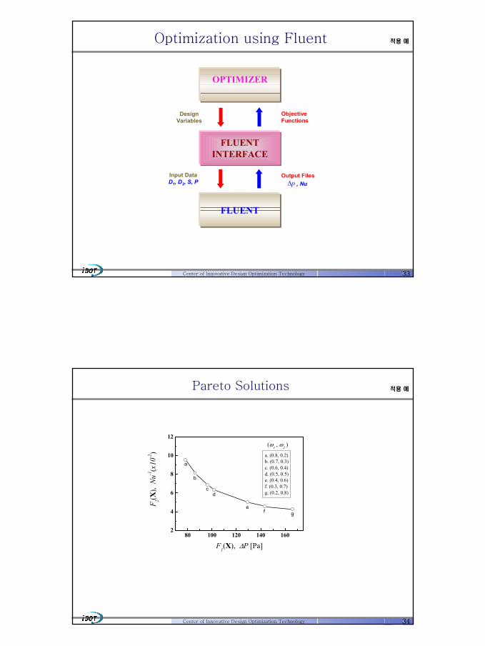
Optimization using Fluent
OPTIMIZER
FLUENTINTERFACE
FLUENT
DesignVariables
ObjectiveFunctions
Input DataD1, D2, S, P
Output Filesp∆ , Nu
적용 예
34Center of Innovative Design Optimization Technology
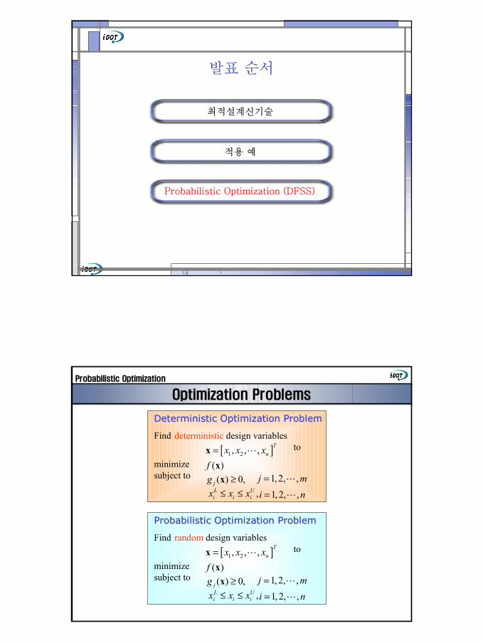
80 100 120 140 1602
4
6
8
10
12
gfe
dc
b
a
a. (0.8, 0.2)b. (0.7, 0.3)c. (0.6, 0.4)d. (0.5, 0.5)e. (0.4, 0.6)f. (0.3, 0.7)g. (0.2, 0.8)
(ω1 , ω
2 )
F 2(X),
Nu-1
(x10
-2)
F1(X), ∆P [Pa]
Pareto Solutions 적용 예
Center of Innovative Design Optimization Technology
발표 순서
최적설계신기술
적용 예
Probabilistic Optimization (DFSS)
..
Optimization ProblemsOptimization Problems
Deterministic Optimization ProblemDeterministic Optimization Problem
Find deterministic design variablesto
minimizesubject to
[ ]1 2, , , Tnx x x=x L
( )f x( ) 0,jg ≥x
,L Ui i ix x x≤ ≤
1, 2, ,j m= L
1, 2, ,i n= L
Probabilistic Optimization ProblemProbabilistic Optimization Problem
Find random design variablesto
minimizesubject to
[ ]1 2, , , Tnx x x=x L
( )f x( ) 0,jg ≥x
,L Ui i ix x x≤ ≤
1, 2, ,j m= L
1, 2, ,i n= L
Probabilistic OptimizationProbabilistic Optimization

..
Random Variable Random Variable ΧΧ
확률밀도함수
누적확률밀도함수
확률밀도함수확률밀도함수((PDF)PDF)
[ ] ( )( )( )
( ) 1
X
XX
X
P x X x dx f xdF xf x
dx
f x dx∞
−∞
≤ ≤ + =
=
=∫
누적확률분포함수누적확률분포함수((CDF)CDF)
[ ]( )XF x P X x= ≤
21 1( ) exp
22X
XXX
xf x µσπσ
− = −
정규분포:
Probabilistic OptimizationProbabilistic Optimization
..
Characterizing Probability Distributions Characterizing Probability Distributions
'1 ( )x Xxf x dxµ µ
∞
−∞= = ∫
( )22 22 ( ) ( )x x x XE x x f x dxσ µ µ µ
∞
−∞= = − = −∫
Mean
Variance
Describe a distribution in terms of
• Average - mean
• Spread - variance
• Symmetry - skewness
• Peakedness - kurtosis
Skewness
Kurtosis
( )3 33 ( ) ( )x x XE x x f x dxµ µ µ
∞
−∞= − = −∫
( )4 44 ( ) ( )x x XE x x f x dxµ µ µ
∞
−∞= − = −∫
Probabilistic OptimizationProbabilistic Optimization

..
SixSix--SigmaSigma
For Normal DistributionsFor Normal Distributions
•• 68.3% of values will fall ±1σ around mean
• 95.5% of values will fall ±2σ around mean
• 99.73% of values will fall ±3σ around mean
• 99.9999998% of values will fall ±6σ around mean
Probabilistic OptimizationProbabilistic Optimization
..
SixSix--SigmaSigma
3.40.00299.99999986
2330.5799.9999435
62006399.99374
66,8032,70099.733
308,73345,40095.462
697,700317,40068.261
Defects per million(with 1.5σ shift)
Defectsper million
PercentVariation
Sigma ±σ
FormerEngineering
Target
NewPhilosophy
' 1.5µ µ σ= + 1.5 Sigma Shift
Probabilistic OptimizationProbabilistic Optimization

Probabilistic Optimization Problems Probabilistic Optimization Problems
Robust Optimization ProblemRobust Optimization Problem
Find
min. s.t.
(1 )f fαµ α σ+ −0,
j jg j gkµ σ+ ≥
Reliability Based Design Reliability Based Design Optimization ProblemOptimization Problem
Find
min. s.t.
,i i i
L Ux x xµ µ µ≤ ≤
( )xf µ[ ( ) 0] ,U
f jP g P≤ ≤x
1 2, , ,
n
T
x x xµ µ µ = xµ L
1, 2, ,j m= L
1,2, ,i n= L1, 2, ,j m= L
1 2, , ,
n
T
x x xµ µ µ = xµ L
Recent RBDO ProblemRecent RBDO Problem
Find
min. s.t.
(1 )f fαµ α σ+ −
[ ( ) 0] ,Uf jP g P≤ ≤x 1, 2, ,j m= L
1 2, , ,
n
T
x x xµ µ µ = xµ L
1,2, ,i n= L,i i i
L Ux x xµ µ µ≤ ≤
1, 2, ,i n= L,i i i
L Ux x xµ µ µ≤ ≤
2x
1x
1x∆
2x∆
cfδfδ
*cx xδ±
rx xδ∗ ±
Robustness of ObjectiveRobustness of Feasibility
Probabilistic OptimizationProbabilistic Optimization
Pfj=P( gj(X) > 0) ≤ Pju, j=1,…,mPfj=P( gj(X) > 0) ≤ Pj
u, j=1,…,m
Minimize
subject to
, 1, 2,...,L Ui i ix x x i n≤ ≤ =
( )f x
Tools Suite
Monte Carlo Simulation
MVFO Method
FORM
, 1, 2,...,L Ui i ix x x i n≤ ≤ =
Probabilistic OptimizationProbabilistic Optimization
Formulation for Reliability Based OptimizationFormulation for Reliability Based Optimization

43
Center of
44Center of Innovative Design Optimization Technology
F.E.Model of Automotive Door and Loading andBoundary Conditions
Model
Program
Design variables
- 자동차 프론트 도어의 유한요소모델
- 테일러드 블랭크를 적용하기 위해 각 파트의 두께와 그 분포를 결정
-FEMB/GENESIS 6.0 (VMA)
- 위상 최적설계 : 각 요소의 정규화된 밀도
- 치수 최적설계 및 이산 설계 : 각 파트의 두께
- 형상 최적설계 : 각 파트의 경계 위치
Constraints
Objective- 위상 최적설계 :
- 치수, 형상 최적설계 및 이산 설계
: 자동차 프론트 도어의 질량 최소화
- 위상 최적설계 : 초기 구조물 질량의 30%- 치수, 형상 최적설계 및 이산 설계 :
초기 모델 대비 변형량과 1차 고유 진동수의 성능 향상
임의의 파트 두께는 이웃하는 파트 두께 대비 2배 이하
단, Φ: 구조물의 굴성, ψ: 고유 진동수
첨자 o : 초기 모델
Example of Tailored Blank Door
ΨΨ
+ΦΦ 0
0
Minimize
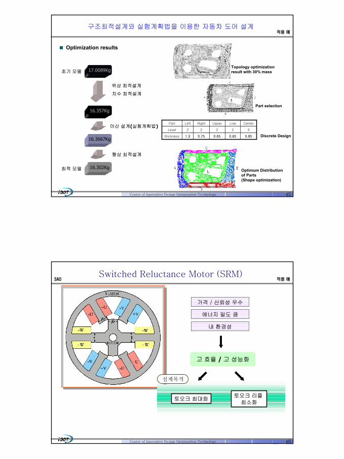
구조최적설계와 실험계획법을 이용한 자동차 도어 설계적용 예
45Center of Innovative Design Optimization Technology
Optimization results
0.850.650.650.751.3thickness
32222Level
CenterLowUpperRightLeftPart
초기 모델
이산 설계(실험계획법)
형상 최적설계
치수 최적설계
16.3667Kg
16.302Kg
17.0089Kg
16.357Kg
위상 최적설계
Topology optimizationresult with 30% mass
Part selection
Discrete Design
Optimum Distributionof Parts (Shape optimization)
최적 모델
구조최적설계와 실험계획법을 이용한 자동차 도어 설계적용 예
46Center of Innovative Design Optimization Technology
가격 / 신뢰성 우수
에너지 밀도 큼
내 환경성
토오크 최대화토오크 리플
최소화
고 효율 / 고 성능화
설계목적
Switched Reluctance Motor (SRM)SAO 적용 예
47Center of Innovative Design Optimization Technology
Objective
Maximize Average Torque
Constraints
Torque ripple
Maximum Current Phase
( )aveT
( ) %20≤ripT
( ) ( )A6max ≤I
Design Variables
Switching on Angle
Switching off Angle
Rotor Pole Arc
( )onθ
( )offθ
( )rβ
Optimization Problem of SRMSAO 적용 예
48Center of Innovative Design Optimization Technology
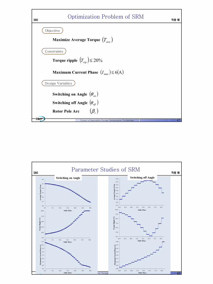
0.0
0.1
0.2
0.3
0.4
0.5
0.6
0.0 5.0 10.0 15.0 20.0 25.0 30.0
Angle (deg.)
Ave
rage
Tor
que
(N-m
)
75.0
80.0
85.0
90.0
95.0
100.0
0.0 5.0 10.0 15.0 20.0 25.0 30.0Angle (deg.)
Tor
que
Rip
ple
(%)
3.0
4.0
5.0
6.0
7.0
8.0
9.0
10.0
11.0
0.0 5.0 10.0 15.0 20.0 25.0 30.0Angle (deg.)
Max
imum
Cur
rent
Pha
se (A
)
0.15
0.16
0.17
0.18
0.19
0.20
0.21
0.22
0.23
0.24
45.0 47.0 49.0 51.0 53.0 55.0 57.0 59.0
Angle (deg.)
Ave
rage
Tor
que
(N-m
)
45.0
55.0
65.0
75.0
85.0
95.0
105.0
45.0 47.0 49.0 51.0 53.0 55.0 57.0 59.0Angle (deg.)
Tor
que
Rip
ple
(%)
4.00
4.05
4.10
4.15
4.20
4.25
4.30
4.35
4.40
45.0 47.0 49.0 51.0 53.0 55.0 57.0 59.0Angle (deg.)
Max
imum
Cur
rent
Pha
se (A
)
Switching on Angle Switching off Angle
Parameter Studies of SRMSAO 적용 예

49Center of Innovative Design Optimization Technology
Convergence History Torque
0
0.1
0.2
0.3
0.4
0.5
0.6
0 1 2 3 4 5 6 7 8 9Iteration
Ave
rage
Tor
que
-1.0
0.0
1.0
2.0
3.0
4.0
5.0
0 1 2 3 4 5 6 7 8 9Iteration
Max
imum
Con
stra
int V
iola
tion
0
0.1
0.2
0.3
0.4
0 10 20 30 40 50 60 70 80 90
Rotation Angle (deg.)
Tor
que
(N-m
)
Initial DesignOptimum Design
Initial
Optimum
onθ offθ rβ aveT ripT maxI
22.4 55.7 38.0 0.30 19.98 4.91
25.2 45.1 30.0 0.17 98.60 4.02
Optimization Results of SRMSAO 적용 예
50
Design Framework
- legacy software and commercial tools
- graphical user interface, window-style menu system
Visual Modeling
Software Integration
Automation of the Design Processes
분산객체 (Distributed Object) 시스템의 지원
The design framework is intended to link together disciplinary analyses in a
distributed, heterogeneous computing environment, and automate data
exchange for the purpose of collaborative design
-Java RMI (Remote Method Invocation)
최적화(Optimization) - MDO
설계 프레임웍다분야통합최적설계

51
Design Philosophy
편의성: 지능형 사용자 인터페이스를 통한 편리한 시스템 사용
Script를 이용한 명령(SC), GUI를 이용한 명령(GC),
SC와 GC는 기능적 동치
다양성: MDO의 특징인 분산컴퓨팅 환경과 다양한 플랫폼을 지원
(Java RMI, Agent)
호환성: CAD/CAE 간 이질적 데이터의 호환성 제공을 위한 표준 데이터
양식에 산업체 국제표준 수용 (STEP, XML)
효율성: 소프트웨어 공학적 시스템 개발을 통한 개발 효율 및 사용 효율
추구 , 객체지향 시스템 개발 방법론(UML)
확장성: 새로운 CAD/CAE 또는 데이터 양식을 수용
(Agent, 객체지향 방법론)
확대성: 대규모 및 소규모 MDO 수요를 모두 만족
잘 정의된 API
설계 프레임웍다분야통합최적설계
52
Framework 개발 환경
Java RMI 을 이용한 분산 환경 구현
Visibroker4.0 Java 및 C++
Windows 관련 개발 환경
Microsoft Visual Studio 6.x
Java 관련 개발 환경
JDK1.3
JBuilder3.5,Visual J++: GUI 구현
Javacc: script 구현
Studio.J: 데이터 입출력 및 분석
UML 시스템 설계 환경
Rational Rose 2000
Configuration Management
ClearCase
C++, Fortran 프로그램 지원
설계 프레임웍다분야통합최적설계

53
EMDIOS
EMDIOSEExtendable xtendable MMultidisciplinary ultidisciplinary DDesign esign IIntegrationntegration& & OOptimization ptimization SSystemystem
Resource Wrapping AutomationPost Process & Monitoring
Database
Various Optimizers &MDO Kernel
Process Integration
EMDIO-L Visual Modeling
설계 프레임웍다분야통합최적설계
54
EMDIOS Architecture
DOE Modules
GlobalOptimizer(s)
Driver Resource
Visual Modeling
EMDIO-L Manager
Unknown Resource
PROCESS Manager
EDOM Manager
Optimization Schedule Template Manager
DATABASE Manager
USER INTERFACE
EMDIO-L Parser
CO MDF IDF STANDARD
MDO Kernel
Message Manager
I/O Manager
EDO
M A
bstract Layer
EDO
M A
bstract Layer
LocalOptimizer(s)
Driver Resource
Non Linear Analysis
Crash Analysis
Experimental Results
ApproximationModules
설계 프레임웍다분야통합최적설계

55
Process Integration
해석 시스템간에는 File Wrapper 가 존재하여 각각 해석 시스템에대해서 투명성을 제공( 인터넷과 레거시 환경을 구분하지 않는다).
자바 RMI를 이용하여 이기종간의 해석 시스템을 호출.
RMI (Remote Method Invocation)
인터넷/인트라넷
Client Server
Optimizer CAE S/WeDOM Server (Mac G4 based)
eDOM Server (Win NT/9X)
eDOM Server (UNIX based)
설계 프레임웍다분야통합최적설계
56
Automation
PROGRAM1.EXEFor Suspension
PROGRAM2.EXEFor Suspension
PROGRAM3.EXEFor Suspension
Design Framework provides to organizations a complete solutionfor the automation of the product design process
설계 프레임웍다분야통합최적설계

57
Various Optimizers
DIRECT Method
Genetic Algorithm
Global Optimizer
ADS (Automated Design Synthesis)
DOT (Design Optimization Tools)
NUOPT iDOT (도입예정)
Local Optimizer
Typical Local Approximation Methods
- One-Point Approximation
- Two-Point Approximation
- Multi-Point Approximation
New Two-Point Approximation Method
- Two-Point Diagonal Quadratic Approximation
Gradient Based Approximation
Typical RSM based on Experimental Design
- Quadratic Approximation Modeling
- Alphabetic Optimality Criteria
New RSM based on Experimental Design
- Subspace CCD/SCD
- Progressive Quadratic Approximation
- Augmented D-optimality
Function Based Approximation
Virtual Analysis
설계 프레임웍다분야통합최적설계
Gradient Based Approximation
Typical RSM based on Experimental Design
- Quadratic Approximation Modeling
- Alphabetic Optimality Criteria
New RSM based on Experimental Design
- Subspace CCD/SCD
- Progressive Quadratic Approximation
- Augmented D-optimality
Function Based Approximation
58
EMDIOS Capabilities
MDO MethodsMDO Methods
다양한 MDO 방법론의 도입
More EfficiencyMore EfficiencyFor ModelingFor Modeling
Windows계열의 인터페이스를이용한 최적화 문제 설정
Parallel ProcessingParallel Processing
MDO문제를 병렬로 처리
Distributed Design SystemDistributed Design System
이기종간의 분산환경 지원
EMDIOEMDIO--LanguageLanguage
NASTRAN 문법의 자체언어를 장착
설계 프레임웍다분야통합최적설계

59
Customization
산업체에서 제공하는해석 관련 컴포넌트 EMDIOS의 서브 컴포넌트
iDOT EMDIOS 산업체 Design Framework
iDOT EMDIOS provides iDOT EMDIOS provides Various Optimization Components Various Optimization Components
and GUI Componentsand GUI Components
설계 프레임웍다분야통합최적설계
60
Rear Multi Link Suspension
Model
Program
Design variables
- Rear Multi Link Suspension
- Analyze Suspension and Steering Characteristics
- In-House Program (developed by Hyundai Motors)
- Coordinates of Hard Points (9)
Rear Multi Link Suspension
Constraints
Objective
- The Sum of Linkage forces Min.
- Assist arm ball joint force ≤ Upper bound
- Upper arm ball joint force ≤ Upper bound
Simple Model
설계 프레임웍다분야통합최적설계