for electrical cash drawers … 1 introduction 1.1 general please read the instructions before...
TRANSCRIPT

INSTRUCTIONSFOR ELECTRICAL CASH DRAWERS
INTEGRATED CASH DRAWERSUNDER-THE-COUNTER CASH DRAWERS
TABLE TOP CASH DRAWERS

Copyright – 2002 Mogler-Kassen GmbH, RappenauPrinted in GermanyAll rights reserved
This document may not be reproduced in any form, either in part or in whole, translated into other languages or distributed to third-parties without the prior written consent of Mogler-Kassen GmbH.
Mogler-Kassen GmbHObere Mühle 17D-74906 Bad Rappenau-Bonfeld, GermanyPhone +49 (0) 70 66 99 44-10Fax +49 (0) 70 66 99 44-11
Internet: http://www.mogler.deE-mail: [email protected]
Edition 1.003/2002
Page
Contents 1
T
I 1
G . . . . . . . . . . . . . . . . . . . . . . . . . . . . . . . . . 1G . . . . . . . . . . . . . . . . . . . . . . . . . . . . . . . . . 1S . . . . . . . . . . . . . . . . . . . . . . . . . . . . . . . . . 1I . . . . . . . . . . . . . . . . . . . . . . . . . . . . . . . . . 2
. . . . . . . . . . . . . . . . . . . . . . . . . . . . . . . . . 2 . . . . . . . . . . . . . . . . . . . . . . . . . . . . . . . . . 3 . . . . . . . . . . . . . . . . . . . . . . . . . . . . . . . . . 3 . . . . . . . . . . . . . . . . . . . . . . . . . . . . . . . . . 3 . . . . . . . . . . . . . . . . . . . . . . . . . . . . . . . . . 4 . . . . . . . . . . . . . . . . . . . . . . . . . . . . . . . . . 4Counter Model) . . . . . . . . . . . . . . . . . . . . 4 . . . . . . . . . . . . . . . . . . . . . . . . . . . . . . . . . 5 . . . . . . . . . . . . . . . . . . . . . . . . . . . . . . . . . 5 . . . . . . . . . . . . . . . . . . . . . . . . . . . . . . . . . 5
able of Contents
ntroductioneneral . . . . . . . . . . . . . . . . . . . . . . . . . . . . . . . . . . . . . . . . . . . . . . . . . . . . . . . .uarantee . . . . . . . . . . . . . . . . . . . . . . . . . . . . . . . . . . . . . . . . . . . . . . . . . . . . . .afety Instructions . . . . . . . . . . . . . . . . . . . . . . . . . . . . . . . . . . . . . . . . . . . . . . . .nstallation . . . . . . . . . . . . . . . . . . . . . . . . . . . . . . . . . . . . . . . . . . . . . . . . . . . . . .
Opening the Cash Drawer for the First Time . . . . . . . . . . . . . . . . . . . . . .Removing the Cash Drawer. . . . . . . . . . . . . . . . . . . . . . . . . . . . . . . . . . . . .
Table Top/Under-The-Counter Cash Drawers . . . . . . . . . . . . . . . . . .Reduced-Depth Cash Drawers . . . . . . . . . . . . . . . . . . . . . . . . . . . . . . .
Installing the Cash Drawer . . . . . . . . . . . . . . . . . . . . . . . . . . . . . . . . . . . . . .Under-The-Counter Cash Drawers. . . . . . . . . . . . . . . . . . . . . . . . . . . .Reduced-Depth Cash Drawers with Mounting Frames (Under-The-
Inserting the Cash Drawer . . . . . . . . . . . . . . . . . . . . . . . . . . . . . . . . . . . . . .Table Top/Under-The-Counter Cash Drawer . . . . . . . . . . . . . . . . . . .Reduced-Depth Cash Drawers . . . . . . . . . . . . . . . . . . . . . . . . . . . . . . .

2
Page
O 6
C . . . . . . . . . . . . . . . . . . . . . . . . . . . . . . . . . 6 . . . . . . . . . . . . . . . . . . . . . . . . . . . . . . . . . 7 . . . . . . . . . . . . . . . . . . . . . . . . . . . . . . . . . 8 . . . . . . . . . . . . . . . . . . . . . . . . . . . . . . . . . 8
O . . . . . . . . . . . . . . . . . . . . . . . . . . . . . . . . 10 . . . . . . . . . . . . . . . . . . . . . . . . . . . . . . . . 10 . . . . . . . . . . . . . . . . . . . . . . . . . . . . . . . . 11
C . . . . . . . . . . . . . . . . . . . . . . . . . . . . . . . . 12M . . . . . . . . . . . . . . . . . . . . . . . . . . . . . . . . 12
M 13
Contents
perationonnecting the Cash Drawer . . . . . . . . . . . . . . . . . . . . . . . . . . . . . . . . . . . . . .
Cash Register Module Type PC-St5 for Parallel Ports (LPT) . . . . . . .Cash Register Module Type PC-St4 for Serial Ports (COM) . . . . . . .Serial Port (COM) Power BLOC – Mains Independent . . . . . . . . . . .
pening the Cash Drawer . . . . . . . . . . . . . . . . . . . . . . . . . . . . . . . . . . . . . . . .Status Request . . . . . . . . . . . . . . . . . . . . . . . . . . . . . . . . . . . . . . . . . . . . . . . .Configuring the Distance that the Cash Drawer Extends . . . . . . . . . . . .
ylinder Lock . . . . . . . . . . . . . . . . . . . . . . . . . . . . . . . . . . . . . . . . . . . . . . . . . . .odels With Lockable Drawer Inserts (DI) . . . . . . . . . . . . . . . . . . . . . . . . . .
aintenance
3
Page
T 14
T . . . . . . . . . . . . . . . . . . . . . . . . . . . . . . . . 14 . . . . . . . . . . . . . . . . . . . . . . . . . . . . . . . . 14 . . . . . . . . . . . . . . . . . . . . . . . . . . . . . . . . 14 . . . . . . . . . . . . . . . . . . . . . . . . . . . . . . . . 14 . . . . . . . . . . . . . . . . . . . . . . . . . . . . . . . . 15
P . . . . . . . . . . . . . . . . . . . . . . . . . . . . . . . . 15T . . . . . . . . . . . . . . . . . . . . . . . . . . . . . . . . 16
. . . . . . . . . . . . . . . . . . . . . . . . . . . . . . . . 17 . . . . . . . . . . . . . . . . . . . . . . . . . . . . . . . . 18
T . . . . . . . . . . . . . . . . . . . . . . . . . . . . . . . . 19O . . . . . . . . . . . . . . . . . . . . . . . . . . . . . . . . 20
. . . . . . . . . . . . . . . . . . . . . . . . . . . . . . . . 20 . . . . . . . . . . . . . . . . . . . . . . . . . . . . . . . . 20
Contents
rouble Shootinghe drawer will not enter the housing . . . . . . . . . . . . . . . . . . . . . . . . . . . . . .
After installation in the housing . . . . . . . . . . . . . . . . . . . . . . . . . . . . . . .After installation in the housing . . . . . . . . . . . . . . . . . . . . . . . . . . . . . . .Cash Drawer With Insert . . . . . . . . . . . . . . . . . . . . . . . . . . . . . . . . . . . .Other Causes . . . . . . . . . . . . . . . . . . . . . . . . . . . . . . . . . . . . . . . . . . . . . .
ower Failure . . . . . . . . . . . . . . . . . . . . . . . . . . . . . . . . . . . . . . . . . . . . . . . . . . .he drawer will no longer open . . . . . . . . . . . . . . . . . . . . . . . . . . . . . . . . . . . .
Replacing the Control Cable. . . . . . . . . . . . . . . . . . . . . . . . . . . . . . . . . .Replacing the Trigger Magnet . . . . . . . . . . . . . . . . . . . . . . . . . . . . . . . . .
he status is no longer displayed . . . . . . . . . . . . . . . . . . . . . . . . . . . . . . . . . . .ther . . . . . . . . . . . . . . . . . . . . . . . . . . . . . . . . . . . . . . . . . . . . . . . . . . . . . . . . . .
The key is broken. . . . . . . . . . . . . . . . . . . . . . . . . . . . . . . . . . . . . . . . . . .The cash drawer pops open after closing . . . . . . . . . . . . . . . . . . . . . . .

4
Page
A 21
R . . . . . . . . . . . . . . . . . . . . . . . . . . . . . . . . 21A . . . . . . . . . . . . . . . . . . . . . . . . . . . . . . . . 22S . . . . . . . . . . . . . . . . . . . . . . . . . . . . . . . . 22
. . . . . . . . . . . . . . . . . . . . . . . . . . . . . . . . 22 . . . . . . . . . . . . . . . . . . . . . . . . . . . . . . . . 22 . . . . . . . . . . . . . . . . . . . . . . . . . . . . . . . . 23 . . . . . . . . . . . . . . . . . . . . . . . . . . . . . . . . 23 . . . . . . . . . . . . . . . . . . . . . . . . . . . . . . . . 24 . . . . . . . . . . . . . . . . . . . . . . . . . . . . . . . . 24 . . . . . . . . . . . . . . . . . . . . . . . . . . . . . . . . 24
C . . . . . . . . . . . . . . . . . . . . . . . . . . . . . . . . 25S . . . . . . . . . . . . . . . . . . . . . . . . . . . . . . . . 32
. . . . . . . . . . . . . . . . . . . . . . . . . . . . . . . . 33 . . . . . . . . . . . . . . . . . . . . . . . . . . . . . . . . 33 . . . . . . . . . . . . . . . . . . . . . . . . . . . . . . . . 34 . . . . . . . . . . . . . . . . . . . . . . . . . . . . . . . . 35 . . . . . . . . . . . . . . . . . . . . . . . . . . . . . . . . 36
Contents
ppendixeplacement Parts . . . . . . . . . . . . . . . . . . . . . . . . . . . . . . . . . . . . . . . . . . . . . . .ccessories . . . . . . . . . . . . . . . . . . . . . . . . . . . . . . . . . . . . . . . . . . . . . . . . . . . . .pecifications . . . . . . . . . . . . . . . . . . . . . . . . . . . . . . . . . . . . . . . . . . . . . . . . . . . .
Cash Register Module Type PC-St5 for Parallel Ports . . . . . . . . . . . . . . .Electrical Specifications . . . . . . . . . . . . . . . . . . . . . . . . . . . . . . . . . . . . . .
Cash Register Module Type PC-St4 for Serial Ports . . . . . . . . . . . . . . . . .Electrical Specifications and Pin Layout . . . . . . . . . . . . . . . . . . . . . . . . .
Serial Port Power BLOC . . . . . . . . . . . . . . . . . . . . . . . . . . . . . . . . . . . . . . . Electrical Specifications and Pin Layout . . . . . . . . . . . . . . . . . . . . . . . .Integrated Power BLOC Connection . . . . . . . . . . . . . . . . . . . . . . . . . .
haracter Set . . . . . . . . . . . . . . . . . . . . . . . . . . . . . . . . . . . . . . . . . . . . . . . . . . .oftware. . . . . . . . . . . . . . . . . . . . . . . . . . . . . . . . . . . . . . . . . . . . . . . . . . . . . . . .
Control Conditions . . . . . . . . . . . . . . . . . . . . . . . . . . . . . . . . . . . . . . . . . . . .Cash Register Module Type PC-St5 for Parallel Ports. . . . . . . . . . . . .Cash Register Module Type PC-St4 for Serial Ports . . . . . . . . . . . . . .Serial Port Power BLOC . . . . . . . . . . . . . . . . . . . . . . . . . . . . . . . . . . . . .
Status Request . . . . . . . . . . . . . . . . . . . . . . . . . . . . . . . . . . . . . . . . . . . . . . . .
1
1
1
before
installing or using the cash drawer for the
ance instructions (see Section 3).
the cylinder lock as well before leaving it
1
vered by a 24 month guarantee.
dling or failure to observe the instructions will ogler is not liable for damages or losses due to
1
that they cannot be damaged by being caught or
d computer off before removing the mains plug!
plug before opening electrical devices (for arts or configuring the interface)!
Introduction
.1 General Please read the instructions
first time. Kindly observe the mainten Lock the cash drawer with
unattended.
.2 GuaranteeAll Mogler cash drawers are co
Please note that improper hanrender warranty claims void. Mimproper operation.
.3 Safety Instructions! Lay and secure all cables so
pulled!
! Always turn the printer an
! Always remove the mains example, when replacing p

C
2
1
n delivery.
drawer type, you must first remove the drawer
1
in the envelope with the instruction manual.
r locked
r unlocked (operating state)
r opens (emergency open as well)
ash Drawers with Electromagnetic Releases
.4 InstallationThe cash drawer is locked upo
Before assembling any cash(see Section 1.4.2).
.4.1 Opening the Cash Drawer for the First Time
The cash drawer key is located
Unlock the cylinder lock. Key position 1 = drawe Key position 2 = drawe Key position 3 = drawe
Open the cash drawer.
3
2
1

ers with Electromagnetic Releases
3
1
nter Cash Drawers
s possible.
s it will go (down on the right and up on the left n pull the drawer out.
e removed from the rails.
wers
s it will go.
o bypass the incorporated spring blocking
ut as far as it will go again.
the top edges of the drawer and pull the drawer
lastic Lever (a)
s it will go.
he rails with a firm tug.
Cash Draw
.4.2 Removing the Cash Drawer
Table Top/Under-The-Cou Pull the drawer out as far a Press plastic lever a as far a
side of the drawer) and the The drawer can now b
Reduced-Depth Cash Dra Pull the drawer out as far a
Pull the drawer gently tmechanism.
Now pull the drawer o Press both lock knobs b on
towards you.
Telescopic Rails Without P Pull the drawer out as far a
Free the drawer from t
a
b

C
4
1
nit, use screws with heads that are as flat as movement of the sliding drawer.
Drawers
ter cash drawer unit to the base plate using drill
wers with Mounting Framesodel)
it to the base plate using keyholes
e
on mounting
r with mounting bracket.
ash Drawers with Electromagnetic Releases
.4.3 Installing the Cash Drawer
! To install the cash drawer upossible to ensure smooth
Under-The-Counter Cash Fasten the under-the-coun
holes c and keyholes d .
Reduced-Depth Cash Dra(Under-The-Counter M
Mount the cash drawer unframe f.
Optional: Table top cash drawe
d
c
e
f
ers with Electromagnetic Releases
5
1
a cash drawer.
nter Cash Drawer
o the cash drawer housing as far as they will go.
side of the drawer into openings
h
on the
ilt the drawer.
rails are automatically blocked.
wers
r as they will go.
ils.
i
and insert tongue
k
into the supports labelled
l
.
utomatically latch into the holes in the drawer.
overcome the incorporated spring blocking
lastic Lever (a)
o the cash drawer housing as far as they will go.
rails with a firm push.
Cash Draw
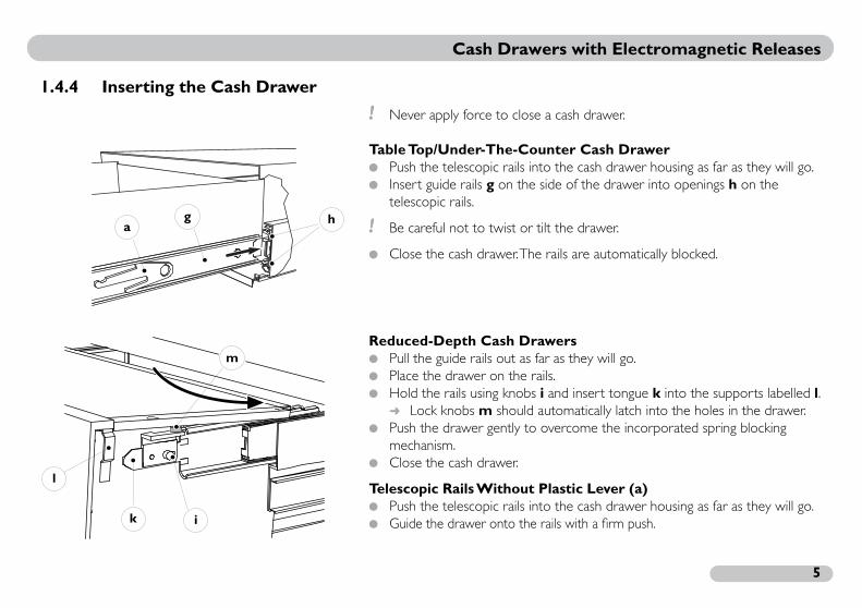
.4.4 Inserting the Cash Drawer
! Never apply force to close
Table Top/Under-The-Cou Push the telescopic rails int Insert guide rails g on the
telescopic rails.
! Be careful not to twist or t
Close the cash drawer. The
Reduced-Depth Cash Dra Pull the guide rails out as fa Place the drawer on the ra Hold the rails using knobs
Lock knobs m should a Push the drawer gently to
mechanism. Close the cash drawer.
Telescopic Rails Without P Push the telescopic rails int Guide the drawer onto the
hga
i
m
k
l
6
2
modules, your cash drawer can be operated with ams used on PCs, cash registers, scales and sales
, the cash drawer is connected to the computer’s are is used to open the cash drawer via the
egister modules for parallel ports, the cash drawer mitted character corresponds to the code set on ister module.
2
be connected if the voltage specified on the data cides with the actual voltage of the power supply.
ents are only available on request.
for pulse operation only.
d on the solenoids, such as from a continuously xample.
Operation
Using the Mogler cash register all standard cash register progrslip printers.
Depending on the module typeserial or parallel port. The softwelectronic controller. On cash rcan only be opened if the transthe DIP switch of the cash reg
.1 Connecting the Cash Drawer! Cash drawers should only
plate or test protocol coin
Special voltage requirem
! The solenoids are designed
Avoid a continuous loapressed signal key, for e

ers with Electromagnetic Releases
7
e PC-St5 for Parallel Ports (LPT)
d computer off before making any connections.
ctor to the parallel port (LPT) on the computer ws.
this cable to the module and fasten it with both
he printer.
rews.
the cash drawer to the cash register module.
nter on again.
Cash Draw
Cash Register Module Typ
! Always turn the printer an
Connect the 25 pin conneand fasten it with both scre
Connect the other end of screws.
Connect the module and t Fasten the plug with the sc Connect the cinch cable on Connect the mains plug. Turn the computer and pri
computer(LPT, parallel)
printer
cashdrawer
mains

C
8
e PC-St4 for Serial Ports (COM)
off before making any connections.
serial port (COM) on the computer (with a 9 or
crews. the cash drawer to the cash register module.
nter back on.
BLOC – Mains Independent
or opened with the Power BLOC module. Unlike St4, this module is not connected to the main BLOC is integrated in the cash drawer housing e Power BLOC can be supplied in a separate onnectors.
off before making any connections.
ash Drawers with Electromagnetic Releases
Cash Register Module Typ
! Always turn the computer
Connect the module to the25 pin D-Sub connector).
Fasten the plug with both s Connect the cinch cable on Connect the mains plug. Turn the computer and pri
Serial Port (COM) Power
The cash drawer is controlled cash register module type PC-electrical network. The Power during production. If desired, thhousing with the appropriate c
! Always turn the computer
computer(COM, serial)
cashdrawer
mains

ers with Electromagnetic Releases
9
LOCconnector to the serial port (COM) on the h both screws.nter on again.
OCe serial port (COM) on the computerconnector).crews. the cash drawer to the cash register module.
nter on again.
Cash Draw
Integrated Power B Connect the (9 or 25 pin)
computer and fasten it wit Turn the computer and pri
External Power BL Connect the module to th
(with a 9 or 25 pin D-Sub Fasten the plug with both s Connect the cinch cable on Turn the computer and pri
computer(COM, serial)
computer(COM, serial)
cashdrawer
C
1
2h drawers are opened by outputting special terface.
d in the cash register software. The cash register r and sends the open signal (see Section 5.5).
cters and their associated switch settings can be
with all established cash register programs, cash rinters. Special programming instructions mple programs) are available on request.
2
e whether a cash drawer is open or closed, takes back of the cash drawer housing. The limit switch
out, see Section 5.3.
ash Drawers with Electromagnetic Releases
0
.2 Opening the Cash DrawerWith all module types, the cascharacters over the selected in
This character is usually definemodule interprets the characte
A table of the permitted charafound in Section 5.4 or 5.5.1.
Mogler cash drawers function registers, scales and sales slip p(software requirements and sa
.2.1 Status Request
The status request, to determinplace using a limit switch on thecan be installed on request.
See Section 5.5.2
For more details on the pin lay

ers with Electromagnetic Releases
11
2 s
extends (travel) is variable on all models:
m of the drawer. front position o = shortest drawer travel when
rear position p = longest extension of drawer
Cash Draw
.2.2 Configuring the Distance that the Cash Drawer Extend
The distance the cash drawer
Attach stop n to the botto Inserting the stop in the
open Inserting the stop in the
when open
o
p n

C
1
2t 28E) can be locked or unlocked using a cylinder
r lockedr unlocked (operating state)r opens (emergency open as well)
cking the cash drawer. This will prevent the cash ked if the key is accidentally turned and avoid key.
sh drawer!
2 I)re placing the insert into the cash drawer.
er of the insert.= cover locked 2 = cover unlocked lock and then remove it.awer.
ash Drawers with Electromagnetic Releases
2
.3 Cylinder LockAll cash drawer models (exceplock:
Unlock the cylinder lock. Key position 1 = drawe Key position 2 = drawe Key position 3 = drawe
! Remove the key after unlodrawer from becoming locaccidental breakage of the
! Never leave a key in the ca
.4 Models With Lockable Drawer Inserts (DAlways remove the cover befo
Unlock the lock on the cov Vertical key position 1 Horizontal key position
Raise the cover to clear the Place the insert into the dr
3
2
1
2
1
ers with Electromagnetic Releases
13
over can be stored in a special storage area under n.gain, remove the insert from the cash drawer.sting on the edge of the insert before shutting it.
3ll bearings clean.
peration of the cash drawer:
see Section 1.4.2).
ings with a non-hardening ball bearing grease.
Cash Draw
With certain models, the cthe drawer during operatio
To close the insert cover a Ensure that the cover is re Turn the lock.
Maintenance! Keep the guide rails and ba
If dirt should hinder smooth o
Remove the cash drawer ( Clean the telescopic rails. Coat the rails and ball bear
1
44
ousing
is in the incorrect position (a1)l position (a2).anchor b to the left and press the lever towards
ousing
been twisted or tilted
t placed correctly on the drawer insert.insert in the cash drawer, you must make sure that d on the insert.rt again.
placed in the drawer correctly..jects below the drawer insert.
s in reverse order.see Section 1.4.4).
4
Trouble Shooting
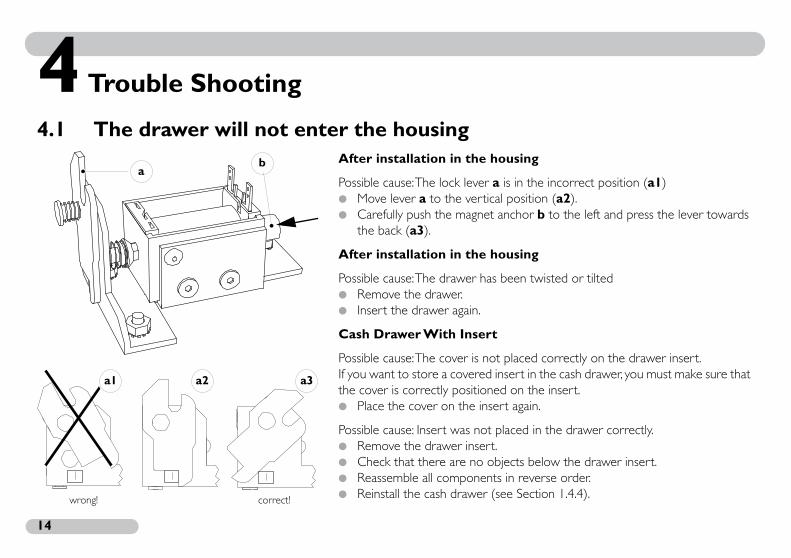
.1 The drawer will not enter the housingAfter installation in the h
Possible cause: The lock lever a Move lever a to the vertica Carefully push the magnet
the back (a3).
After installation in the h
Possible cause: The drawer has Remove the drawer. Insert the drawer again.
Cash Drawer With Insert
Possible cause: The cover is noIf you want to store a covered the cover is correctly positione Place the cover on the inse
Possible cause: Insert was not Remove the drawer insert Check that there are no ob Reassemble all component Reinstall the cash drawer (
ba
wrong! correct!
a3a1 a2
ers with Electromagnetic Releases
15
is in the unlocked position.
cking the drawer.o objects behind the cash drawer.
r ball bearings are dirty.3)
4ental unplugging, you must open the cash drawer
ency Open
d power is available or that the mains plug is
Cash Draw
Other Causes
Possible cause: Lock is closed. Make certain that the lock
Possible cause: Objects are blo Make sure that there are n
Possible cause: The guide rails o See Maintenance (Section
.2 Power FailureDuring a power failure or accidusing the cylinder lock.
See Section 2.3: Emerg
Make sure that the requireconnected.

C
1
4
r cords are connected. the printer is connected and ready for operation.s.
rigger character has been selected. then restart it again.
problem:nal devices and unplug the mains cord.see Section 1.4.2).the trigger magnet. cash drawer housing (see Section 1.4.3).
or visible damage. magnet he Trigger Magnet).le has not been caught or damaged. control cable he Control Cable).
ash Drawers with Electromagnetic Releases
6
.3 The drawer will no longer open
Proceed as follows: Make certain that all powe If necessary, check whether Check all cable connection
See Section 2.1 Make certain the correct t Turn the computer off and
If you still cannot solve the Unplug the cables to exter Remove the cash drawer ( Check the connections to
If necessary, remove the Check the trigger magnet f
If necessary, replace the(see below: Replacing t
Ensure that the control cab If necessary, replace the
(see below: Replacing t
ers with Electromagnetic Releases
17
blenal devices and unplug the mains cord.ection 1.4.2).ousing (see Section 1.4.3).
e-Counter Cash Drawer the base plate of the cash drawer housing.m the housing.
s and connections of the cables!
d solder connections!
guard f.
s in reverse order.see Section 1.4.4).
sh Drawers with Mounting Frames
s and connections of the cables!
d solder connections!
guard f.
s in reverse order.see Section 1.4.4).
Cash Draw
Replacing the Control Ca Unplug the cables to exter Remove the drawer (see S Remove the cash drawer h
Table Top/Under-Th Remove the six nuts under Remove the base plate fro
! Make a note of the colour
! Remove all cable, screw an
Remove nut e from cable Replace the control cable. Reassemble all component Reinstall the cash drawer (
Reduced-Depth Ca
! Make a note of the colour
! Remove all cable, screw an
Remove nut e from cable Replace the control cable. Reassemble all component Reinstall the cash drawer (
d
f
c
e

C
1
gnetnal devices and unplug the mains cord.see Section 1.4.2).ousing (see Section 1.4.3).
e-Counter Cash Drawer the base plate of the cash drawer housing.m the housing.
s and connections of the cables!
o the trigger magnet g.belled h..s in reverse order.see Section 1.4.4).
sh Drawers with Mounting Frames
s and connections of the cables!
o the trigger magnet.belled h..s in reverse order.see Section 1.4.4).
ash Drawers with Electromagnetic Releases
8
Replacing the Trigger Ma Unplug the cables to exter Remove the cash drawer ( Remove the cash drawer h
Table Top/Under-Th Remove the six nuts under Remove the base plate fro
! Make a note of the colour
Remove the connections t Remove the two screws la Replace the electromagnet Reassemble all component Reinstall the cash drawer (
Reduced-Depth Ca
! Make a note of the colour
Remove the connections t Remove the two screws la Replace the electromagnet Reassemble all component Reinstall the cash drawer (
g
h

ers with Electromagnetic Releases
19
4ransmission.
nnected correctly. on the limit switch in the cash drawer housing are
hooting information, see Section 4.3: able
le has not been caught or broken.ntrol cable.ing the Control Cable
is defective.
nal devices and unplug the mains cord!
see Section 1.4.2).ousing (see Section 1.4.3).
e-Counter Cash Drawer the base plate of the cash drawer housing.m the housing.
s and connections of the cables!
Cash Draw
.4 The status is no longer displayedPossible cause: Incorrect data t
Check that all cables are co Ensure that the connectors
not disconnected. For additional trouble s
Replacing the Control C Ensure that the control cab If necessary, replace the co
See Section 4.3: Replac
Possible cause: The limit switch
! Unplug the cables to exter
Remove the cash drawer ( Remove the cash drawer h
Table Top/Under-Th Remove the six nuts under Remove the base plate fro
! Make a note of the colour! Remove all connectors!
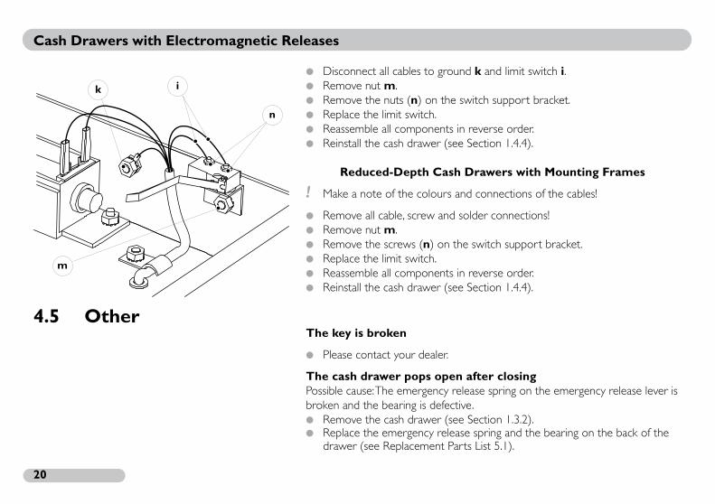
C
2
und k and limit switch i.
e switch support bracket.
s in reverse order.see Section 1.4.4).
sh Drawers with Mounting Frames
s and connections of the cables!
d solder connections!
the switch support bracket.
s in reverse order.see Section 1.4.4).
4
en after closing release spring on the emergency release lever is ctive.see Section 1.3.2).ease spring and the bearing on the back of the Parts List 5.1).
ash Drawers with Electromagnetic Releases
0
Disconnect all cables to gro Remove nut m. Remove the nuts (n) on th Replace the limit switch. Reassemble all component Reinstall the cash drawer (
Reduced-Depth Ca
! Make a note of the colour
Remove all cable, screw an Remove nut m. Remove the screws (n) on Replace the limit switch. Reassemble all component Reinstall the cash drawer (
.5 OtherThe key is broken
Please contact your dealer.
The cash drawer pops opPossible cause: The emergencybroken and the bearing is defe Remove the cash drawer ( Replace the emergency rel
drawer (see Replacement
m
i
n
k

21
55
1
Wi
6
8
5
2
7
9
Appendix
.1 Replacement Partshen ordering replacement parts, please specify the
tem number, cash or drawer type and the serial number.
Fig. Item No. Description1 900-001 Cylinder Lock with Lock Spring
2 900-010 Emergency Release Lever
3 900-002 Emergency Release Spring
4 900-003 Stop Spring
5 900-004 Micro Switch
6 900-005 Magnet
7 900-007 Lock Mechanism
900-008 Bearing (Back of Drawer)
8 900-100 Control Cable (Specify interface type!)
9 900-009 Rail Set (Pair): Guide Rails and Telescopic Rails (complete set)
10 910-011 Spring Blocking Mechanism (Reduced-Depth Cash Drawer)
910-012 Drawer Blocking Mechanism (Reduced-Depth Cash Drawer)(Bottom of Drawer)
910-001 Cash Register Module Type PC-St5
910-002 Cash Register Module Type PC-St4
910-003 Power BLOC
910-090 Print Simulator
4
3
10

C
2
5tional accessories such as drawer equipment and ns and banknotes.
ee operation of your product, we recommend nserts provided by Mogler GmbH.
5
5
230 V10 mA2.3 W
24 V300 mA
60 ms< t <200 ms3 N
ash Drawers with Electromagnetic Releases
2
.2 AccessoriesConsult our catalogue for addistorage compartments for coi
To ensure optimum, trouble frthat you only use the drawer i
.3 Specifications
.3.1 Cash Register Module Type PC-St5 for Parallel Ports
Electrical Specifications
Supply VoltageSupply CurrentPowerPulse VoltagePulse CurrentPulse DurationMagnet (with Lift of 5 mm)

23
5
nd Pin Layout
230 V10 mA2.3 W
24 V300 mA
60 ms< t <200 ms3 N
.3.2 Cash Register Module Type PC-St4 for Serial Ports
Electrical Specifications a
Supply VoltageSupply CurrentPowerPulse VoltagePulse CurrentPulse DurationMagnet (with Lift of 5 mm)
2513
141
25-pin conn. to theserial pc interface
123 45 678
TXD RTSCTSDSRRTS
DTR
white
brown
1011 1213 14151617
9
1819 202122232425
95
61
9-pin conn. to theserial pc interface
123 45 6789
TXD DTRGNDDSRRTSCTS
white
brown
C
2
5
and Pin Layout
Connection
15 V1A
35 ms3 N
r
rcontrol cablewhite
(DTR)
– trigger magnet
brown(RTS)
ash Drawers with Electromagnetic Releases
4
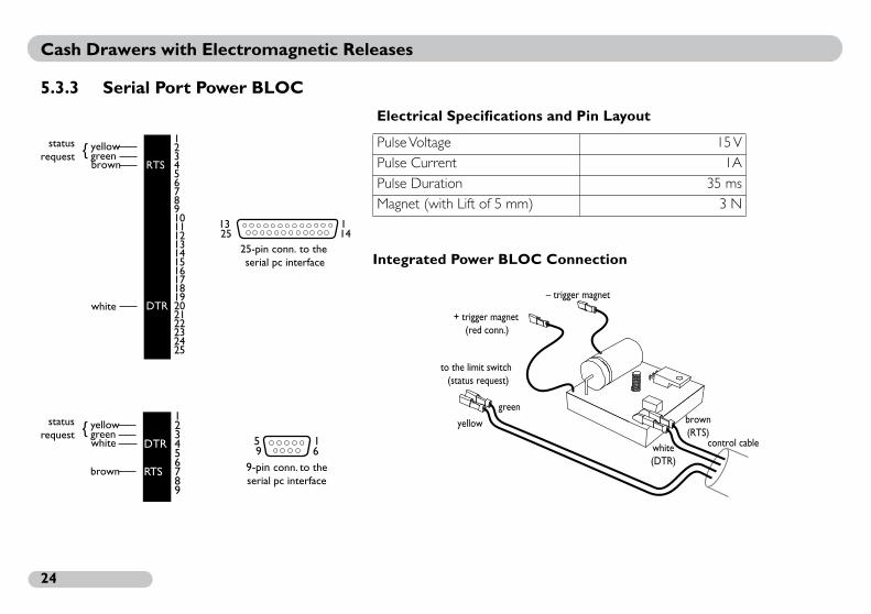
.3.3 Serial Port Power BLOC
Electrical Specifications
Integrated Power BLOC
Pulse VoltagePulse CurrentPulse DurationMagnet (with Lift of 5 mm)
2513
141
25-pin conn. to theserial pc interface
brown
white
123 45 678
RTS
DTR
1011 1213 14151617
9
1819 202122232425
yellowgreenstatus
equest
95
61
9-pin conn. to theserial pc interface
123 45 6789
DTR
RTS
white
brown
yellowgreenstatus
equest
green
to the limit switch(status request)
yellow
+ trigger magnet(red conn.)
ers with Electromagnetic Releases
25
5
Bin. Char. Comment0001 01000001 01010001 01100001 01110001 10000001 10010001 10100001 10110001 11000001 11010001 11100001 11110010 00000010 0001 !
0010 0010 ‘‘
0010 0011 #
0010 0100 $
0010 0101 %
0010 0110 &
0010 0111 ‘
Cash Draw
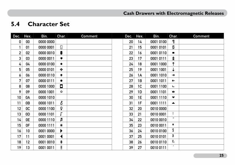
.4 Character Set
Dec. Hex. Bin. Char. Comment Dec. Hex.0 00 0000 0000 20 141 01 0000 0001 21 152 02 0000 0010 22 163 03 0000 0011 23 174 04 0000 0100 24 185 05 0000 0101 25 196 06 0000 0110 26 1A 7 07 0000 0111 27 1B 8 08 0000 1000 28 1C9 09 0000 1001 29 1D
10 0A 0000 1010 30 1E11 0B 0000 1011 31 1F12 0C 0000 1100 32 2013 0D 0000 1101 33 2114 0E 0000 1110 34 2215 0F 0000 1111 35 2316 10 0001 0000 36 2417 11 0001 0001 37 2518 12 0001 0010 38 2619 13 0001 0011 39 27

C
2
Bin. Char. Comment0011 1100 <
0011 1101 =
0011 1110 >
0011 1111 ?
0100 0000 @
0100 0001 A
0100 0010 B
0100 0011 C
0100 0100 D
0100 0101 E
0100 0110 F
0100 0111 G
0100 1000 H
0100 1001 I
0100 1010 J
0100 1011 K
0100 1100 L
0100 1101 M
0100 1110 N
0100 1111 O
ash Drawers with Electromagnetic Releases
6
Dec. Hex. Bin. Char. Comment Dec. Hex.40 28 0010 1000 ( 60 3C41 29 0010 1001 ) 61 3D42 2A 0010 1010 * 62 3E43 2B 0010 1011 + 63 3F44 2C 0010 1100 , 64 4045 2D 0010 1101 - 65 4146 2E 0010 1110 . 66 4247 2F 0010 1111 / 67 4348 30 0011 0000 0 68 4449 31 0011 0001 1 69 4550 32 0011 0010 2 70 4651 33 0011 0011 3 71 4752 34 0011 0100 4 72 4853 35 0011 0101 5 73 4954 36 0011 0110 6 74 4A 55 37 0011 0111 7 75 4B 56 38 0011 1000 8 76 4C57 39 0011 1001 9 77 4D58 3A 0011 1010 : 78 4E59 3B 0011 1011 ; 79 4F

ers with Electromagnetic Releases
27
Bin. Char. Comment0110 0100 d
0110 0101 e
0110 0110 f
0110 0111 g
0110 1000 h
0110 1001 i
0110 1010 j
0110 1011 k
0110 1100 l
0110 1101 m
0110 1110 n
0110 1111 o
0111 0000 p
0111 0001 q
0111 0010 r
0111 0011 s
0111 0100 t
0111 0101 u
01110110 v
0111 0111 w
Cash Draw
Dec. Hex. Bin. Char. Comment Dec. Hex.80 50 0101 0000 P 100 6481 51 0101 0001 Q 101 6582 52 0101 0010 R 102 6683 53 0101 0011 S 103 6784 54 0101 0100 T 104 6885 55 0101 0101 U 105 6986 56 0101 0110 V 106 6A 87 57 0101 0111 W 107 6B 88 58 0101 1000 X 108 6C89 59 0101 1001 Y 109 6D90 5A 0101 1010 Z 110 6E91 5B 0101 1011 [ 111 6F92 5C 0101 1100 \ 112 7093 5D 0101 1101 ] 113 7194 5E 0101 1110 ^ 114 7295 5F 0101 1111 _ 115 7396 60 0110 0000 116 7497 61 0110 0001 a 117 7598 62 0110 0010 b 118 7699 63 0110 0011 c 119 77
C
2
Bin. Char. Comment1000 1100 å
1000 1101 ç
1000 1110 ƒ1000 1111 ≈1001 0000 …1001 00011001 0010 ∆1001 0011 Ù1001 0100 ˆ1001 01011001 0110 ˚1001 0111 ˙1001 1000 ˝1001 1001 ÷1001 1010 ‹1001 1011 ¢1001 1100 £1001 1101 •1001 11101001 1111 ƒ
ash Drawers with Electromagnetic Releases
8
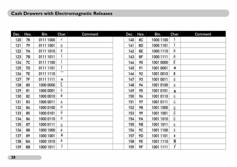
Dec. Hex. Bin. Char. Comment Dec. Hex.120 78 0111 1000 x 140 8C121 79 0111 1001 y 141 8D122 7A 0111 1010 z 142 8E123 7B 0111 1011 143 8F124 7C 0111 1100 | 144 90125 7D 0111 1101 145 91126 7E 0111 1110 ~ 146 92127 7F 0111 1111 147 93128 80 1000 0000 Ä 148 94129 81 1000 0001 Å 149 95130 82 1000 0010 Ç 150 96131 83 1000 0011 ‚ 151 97132 84 1000 0100 ‰ 152 98133 85 1000 0101 Ö 153 99134 86 1000 0110 Ü 154 9A 135 87 1000 0111 Á 155 9B 136 88 1000 1000 Í 156 9C137 89 1000 1001 ë 157 9D138 8A 1000 1010 Ç 158 9E139 8B 1000 1011 ï 159 9F
ers with Electromagnetic Releases
29
Bin. Char. Comment1011 0100 ¥
1011 0101 µ
1011 0110 ∂
1011 0111 ∑
1011 1000 ∏
1011 1001 π
1011 1010 ∫
1011 1011 ª
1011 1100 º
1011 1101 Ω
1011 1110 æ
1011 1111 ø
1100 0000 ¿
1100 0001 ¡
1100 0010 ¬
1100 0011 √
1100 0100 ƒ
1100 0101 ≈
1100 0110 ∆
1100 0111 «
Cash Draw
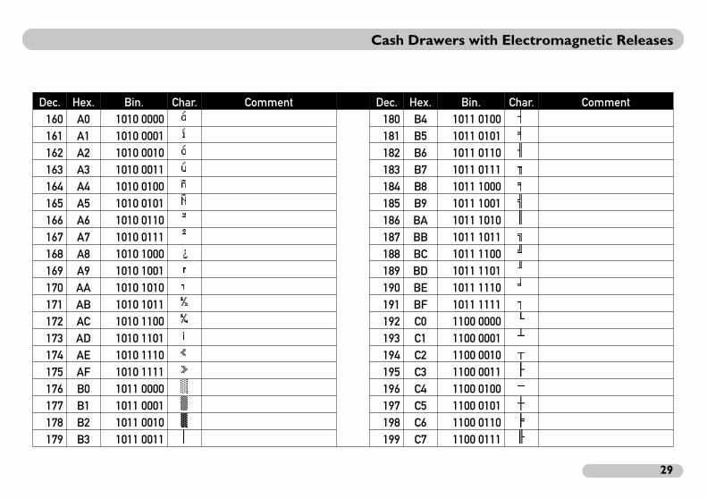
Dec. Hex. Bin. Char. Comment Dec. Hex.160 A0 1010 0000 † 180 B4161 A1 1010 0001 ° 181 B5162 A2 1010 0010 ¢ 182 B6163 A3 1010 0011 £ 183 B7164 A4 1010 0100 § 184 B8165 A5 1010 0101 • 185 B9166 A6 1010 0110 ¶ 186 BA167 A7 1010 0111 ß 187 BB168 A8 1010 1000
?188 BC
169 A9 1010 1001 © 189 BD170 AA 1010 1010 ™ 190 BE171 AB 1010 1011 ´ 191 BF172 AC 1010 1100 ¨ 192 C0173 AD 1010 1101 ≠ 193 C1174 AE 1010 1110 Æ 194 C2175 AF 1010 1111 Ø 195 C3176 B0 1011 0000 ∞ 196 C4177 B1 1011 0001 ± 197 C5178 B2 1011 0010 ≤ 198 C6179 B3 1011 0011 ≥ 199 C7

C
3
Bin. Char. Comment1101 1100 ‹
1101 1101 ›
1101 1110 fi
1101 1111 fl
1110 0000 ‡
1110 0001 ·
1110 0010 ‚
1110 0011 „
1110 0100 ‰
1110 0101 σ1110 0110 µ1110 0111 Á
1110 10001110 1001 θ1110 1010 Í
1110 1011 δ1110 1100 Ï
1110 1101 Ì
1110 1110 Ó
1110 1111
ash Drawers with Electromagnetic Releases
0
Dec. Hex. Bin. Char. Comment Dec. Hex.200 C8 1100 1000 » 220 DC201 C9 1100 1001 … 221 DD202 CA 1100 1010 222 DE203 CB 1100 1011 223 DF204 CC 1100 1100 224 E0205 CD 1100 1101 225 E1206 CE 1100 1110 Œ 226 E2207 CF 1100 1111 œ 227 E3208 D0 1101 0000 – 228 E4209 D1 1101 0001 — 229 E5210 D2 1101 0010 “ 230 E6211 D3 1101 0011 ” 231 E7212 D4 1101 0100 ‘ 232 E8213 D5 1101 0101 ’ 233 E9214 D6 1101 0110 ÷ 234 EA215 D7 1101 0111 ÷ 235 EB216 D8 1101 1000 236 EC217 D9 1101 1001 ä 237 ED218 DA 1101 1010 ⁄ 238 EE219 DB 1101 1011 € 239 EF

ers with Electromagnetic Releases
31
har. Comment±≥≤Ùıˆ˜¯˘˙˚¸˝˛
Cash Draw
Dec. Hex. Bin. C240 F0 1111 0000241 F1 1111 0001242 F2 1111 0010243 F3 1111 0011244 F4 1111 0100245 F5 1111 0101246 F6 1111 0110247 F7 1111 0111248 F8 1111 1000249 F9 1111 1001250 FA 1111 1010251 FB 1111 1011252 FC 1111 1100253 FD 1111 1101254 FE 1111 1110255 FF 1111 1111

C
3
5ith all established cash register programs. Special
tware requirements and sample programs) are
h drawer, the software for the Power BLOC must tions:
.ndshake cables with the prescribed frequency. ch status query.
ms (source code available), two routines differ r the interface component.
ge supports direct port access, the Turbo Pascal this language.
lowing functions:
ddress the interface component connected to
n of the first interface (COM1)of Power BLOC on COM1atus of a switch connected to COM1
ash Drawers with Electromagnetic Releases
2
.5 SoftwareMogler cash drawers function wprogramming instructions (sofavailable on request.
In addition to operating the casalso support the following func
Initialization of the interface Polarity reversal of both ha Implementation of the swit
Of the six Turbo Pascal prograbecause of the base address fo
If another programming languaprograms can be converted to
The programs perform the fol
Similarly, the programs would aCOM2 using Index “2”.
Program FunctionINI1.PAS InitializatioOEFFNEN1.PAS Opening STATUS1.PAS Query st
ers with Electromagnetic Releases
33
s EXE files. The menu-based RS232.EXE program e aforementioned programs. If required, the OM4) can be determined as well.
5
e PC-St5 for Parallel Ports
cash drawer is entered on the computer and sent d character coincides with the code on the DIP ned via the control module.
cter for opening the cash drawer:nter off.nal devices and unplug the mains cable.n the bottom of the cash register module.
itch..ing is binary value 0101 1111. This corresponds to er (_).es (Bin.) and the corresponding character (Char.) 5.4.
ly work when a printer is connected and ready imulator (item no. 910-090) is attached.
Cash Draw
These programs are available aperforms all the functions of thinterface number (COM1 to C
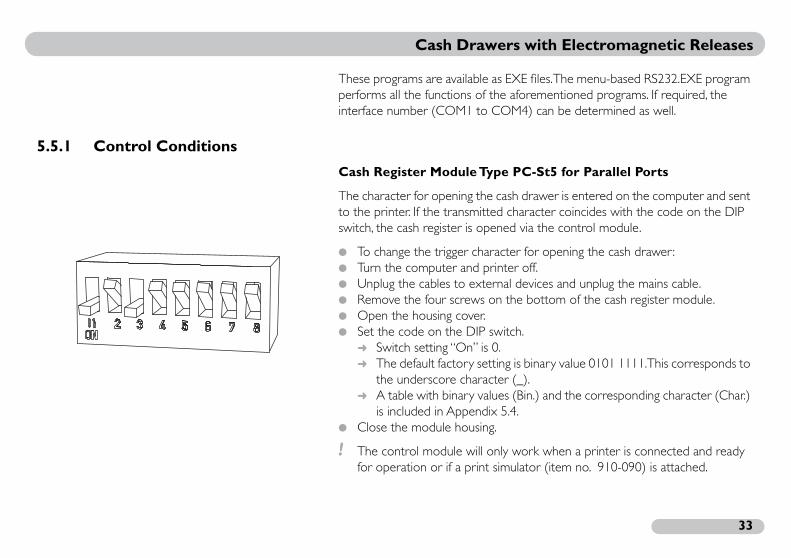
.5.1 Control Conditions
Cash Register Module Typ
The character for opening the to the printer. If the transmitteswitch, the cash register is ope
To change the trigger chara Turn the computer and pri Unplug the cables to exter Remove the four screws o Open the housing cover. Set the code on the DIP sw
Switch setting “On” is 0 The default factory sett
the underscore charact A table with binary valu
is included in Appendix Close the module housing.
! The control module will onfor operation or if a print s

C
3
e PC-St4 for Serial Ports
ree signal variations from logical 1 (-3 V...-12 V) to ccur within 200 ms. Voltage peaks (for example, of the PC) are distinguished from valid ASCII rect opening of the cash drawer.
ash Drawers with Electromagnetic Releases
4
Cash Register Module Typ
To open the drawer, at least thlogical 0 (+3 V...+12 V) must oduring shut down and startup characters. This prevents incor
12V
3V0V
-3V
-12V
opt. level min. levelrequired
logical 0
logical 1
t
> 20µs
> 20µs
t<200ms

ers with Electromagnetic Releases
35
, the signal from Bit 0 and Bit 1 is changed via the In the closed state (drawer closed), the DTR and RTS at -12V.
ting State):
polarity of both levels are reversed approx. ten t.
to the resting state levels again.
for the next trigger event only when the voltage er the cash drawer has been triggered.
it 1 Bit 01
TS approx. -12V DTR approx. +12V
Cash Draw
Serial Port Power BLOC
For interface component 8250MCR modem control register. connection is at approx. +12V
Modem Control Register (Res
To trigger the cash drawer, thetimes for ten ms and then rese
The outputs must then return
! The capacitor is rechargedlevel returns to logical 1 aft
BLogical State 0Level R
t
t
12V
0V
-12V
12V
0V
-12V
10ms
DTR
RTS
triggering thecash drawer resting stateresting state
10ms

C
3
5
over the TXD (output) and RXD (input) data whether data transmission from output to input
ible = switch closed (drawer extended)ossible = switch open (drawer in housing)
ash Drawers with Electromagnetic Releases
6
.5.2 Status Request
The status request takes placelines. The software determinescan take place.
Data transmission poss Data transmission not p

We would be happy to advise you. Give us a call!
Mogler-Kassen GmbHObere Mühle 17D-74906 Bad Rappenau-Bonfeld, GermanyPhone +49 (0) 70 66 99 44-10 Fax +49 (0) 70 66 99 44-11
Internet: http://www.mogler.deE-mail: [email protected]
Printed in Germany03/2002