for brushless motors over 5 - hobbicomanuals.hobbico.com/dtx/dtxm1300-manual-v2.pdf · for...
TRANSCRIPT

Brushless Programmable ESCFor Brushless Motors Over 5.5T
DTXM1300 Mnl 2.0© 2010 Hobbico,® Inc.
DuraTrax’s DE10 ESC is great for many 1/10th scale applications, regardless of motor type. Very smooth and precise control results in no cogging - even at low speeds! A huge set of adjustable features further broadens the number of useful applications, including on and off-road cars & trucks, as well as crawlers. A powerful BEC circuit allows for the use of high-torque/digital steering servos. An optional digital handheld programmer is great for quick, easy setup changes while at the track, and for downloading various types of performance data for post-race analysis.
It is strongly recommended to completely read this manual before use! Damage resulting from misuse or modifi cation will void your warranty.
Features and Specifi cations● The DE10 ESC is designed to be used with
brushless motors having as few as 5.5 turns - great for intermediate to racing applications.
● Includes sensored brushless, sensorless brushless, and brushed motor modes for great versatility.
● Powerful 6 volt, 3 amp linear BEC.● Multi-color LEDs and audible tones allow for easy
manual setup.● 19 manually programmable features. ● On/off power switch.● Sensored brushless mode is great for optimum
precision and control at any speed – great for 2
crawling and racing on challenging courses with low cogging and smooth control even at low speeds.
● Optional Digital Programmer (DTXM1350) is great for quick setup changes at the track, and also for downloading ESC speed, temperature, and current readings from the ESC.
Important Precautions● Disconnect the battery from the ESC
immediately if the ESC or battery becomes hot!! Allow the ESC or battery to cool down before reconnecting.
● NEVER use more than the specifi ed voltage on the ESC’s input.
● ALWAYS mount the ESC in a position where free air can fl ow across it during operation.
● ALWAYS turn on the transmitter before connecting the battery to the ESC.
● ALWAYS disconnect the battery from the ESC when not in use.
● Make sure the input battery is fully charged before connecting to the ESC, so the low voltage cutoff feature can function properly.
● Do not attempt to use with brushed motors while in brushless mode, and vice-versa.
● Use heat-shrink tubing to insulate any bare wires between the motor battery and ESC, and from the ESC to the motor, to prevent a short circuit.
● Allow the ESC to cool before touching. 3

● Do not run the car near water! Never allow water, moisture, or any foreign material onto the ESC’s PC board.
● Do not allow metal/conductive materials to accidentally make contact across all motor/battery posts.
● Never turn on the ESC before plugging it into the Rx and switching on the transmitter (Tx).
● Keep out of reach of children.● DuraTrax is not responsible for incidental
damage or personal injury as a result of misuse of this product.
Glossary of TermsCapacity and milli-amp hours (mAh): the amount of energy a battery can store is called its capacity. A battery’s capacity is rated in “mAh” or milli-amp hours, and should be printed on the battery’s label.Amps (A): The unit of measure for charge or discharge current.Milli-amps (mA): A unit of measure for current, being amps (A) multiplied by 1000 and listed as “mA”. So 2.5A is the same as 2500mA (2.5 × 1000). Or, to convert mA to amps, divide the mA number by 1000. So 25mA is the same as 0.025A (25 divided by 1000).Nominal voltage (V): a unit of voltage that one might expect to measure on a battery pack at any given test point. This is not the minimum or maximum possible voltage. If not printed on the battery’s label, consult 4

your battery supplier or determine the proper pack voltage as shown here:
BatteryType
Number of CellsWired In Series
NominalPack Voltage
LiPo
LiFe
NiCd or NiMH
2 (“2S”)
2 (“2S”)
6
7.4V
6.6V
7.2V
Step 1 – Mounting the ESCThe following information can help the ESC perform at maximum effi ciency and minimize the chance of overheating and radio interference problems.
AirFlow
Mount the ESC to obtain maximum parallel airflow THROUGH the heat sink. This is especially important when using the maximum number of cells on the input and/or when ambient temperatures are very high. For off-road cars, or cars with a metal or graphite chassis, mount the ESC on the chassis, and the receiver and antenna on the rear shock tower to reduce radio interference. Do NOT pack the ESC with foam padding as it will not allow the ESC to properly radiate heat and likely cause a thermal shutdown.
1. Locate the ESC in a position to allow for good airfl ow, with as little obstruction from the model’s outer body or exterior dirt and debris as possible.
2. Mount the ESC using double-sided mounting tape.
IMPORTANT!
Figure 1
Table 1
5

3. Mount the ON/OFF switch in a convenient place. Ensure that it is securely mounted, using mounting tape or screws in a location where it cannot be easily turned off by objects on the track or rough terrain.
Step 2 – Motor ConnectionsCONNECTING BRUSHLESS MOTORSSensored and Sensorless
Each of the three motor leads is made of high quality 13 gauge, silicone insulated wire. These leads have no polarity and can be installed into any of the three motor connections. If the motor runs in reverse, you will have to switch any two of the leads. If a sensored motor is used, be sure to connect the sensor cable to both the motor and ESC. Once connected, make sure all connections are insulated electrically. Failure to do so could result in permanent damage to the motor/ESC, and void all warranties.
+−Battery
Re
d
Blac
k
Sensor
YellowC
B
A
CB
BRUSHLESSMOTOR
A
Orange
–
+
–
+Blue
Figure 2
6

CONNECTING BRUSHED MOTORS
There are two options for connecting brushed motors. The motors can be connected as one-way (forward only) or two-way (forward and reverse). When using a brushed DC motor, please ensure that the confi guration between the ESC and the motor must be in accordance with the selected programming in the ESC (forward or forward/reverse). See the detailed confi guration in Figure 3.
INSTALLING FILTERS
Brushed motors generate radio noise which can interfere with your Rx and cause problems. Check your motor to see if it has capacitors installed on
+−Battery
C
B
A
–BRUSHEDMOTOR
+
Yellow
Orange
2 Way
C
B
A
–BRUSHEDMOTOR
+
1 Way
+−Battery
–
+
–
+
–
+
–
+Blue
Yellow
Orange
Re
d
Blac
k
Re
d
Blac
k
Blue
Figure 3
7
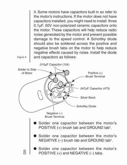
it. Some motors have capacitors built in so refer to the motor’s instructions. If the motor does not have capacitors installed, you might need to install three 0.1µF, 50V non-polarized ceramic capacitors onto the motor. These capacitors will help reduce radio noise generated by the motor and prevent possible damage to the speed control. A Schottky diode should also be soldered across the positive and negative brush tabs on the motor to help reduce negative effects caused by noise. Install the diode and capacitors as follows:
● Solder one capacitor between the motor’s POSITIVE (+) brush tab and GROUND tab†.
● Solder one capacitor between the motor’s NEGATIVE (–) brush tab and GROUND tab†.
● Solder one capacitor between the motor’s POSITIVE (+) and NEGATIVE (–) tabs.
Negative (−)Brush Terminal
Schottky Diode
Silver Band
.047µF Capacitor (473)
.010µF Capacitor (104)
Solder to Sideof Motor Positive (+)
Brush Terminal
Figure 4
8

● Solder the Schottky diode between the motor’s positive and negative brush tabs. Make sure the end of the Schottky diode with the colored band is connected to the motor’s POSITIVE (+) band.
† Solder to the can of the motor if your motor doesn’t have a ground tab.
Step 3 – Necessary Transmitter Settings
For proper ESC operation, it’s very important to set the transmitter’s throttle channel adjustments, as follows:
1. Set the throttle channel’s travel adjustment (ATV, EPA or ATL) to the MAXIMUM setting.
2. Set the throttle trim and sub-trim to neutral or zero.
3. Set the throttle channel’s reversing switch to reverse on Futaba transmitters. Other transmitters might require you to set the throttle reversing switch to normal.
Step 4 – Receiver Connector Polarities
By simply clipping off the tab on the side of the connector using wire cutters, it can be directly connected to any Futaba® J, Airtronics “Z”, Hitec “S”, or JR receiver. For proper connection refer to your radio’s manual. WARNING: This connector is NOT directly compatible with the old Airtronics 9
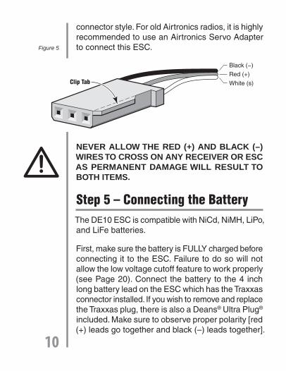
connector style. For old Airtronics radios, it is highly recommended to use an Airtronics Servo Adapter to connect this ESC.
NEVER ALLOW THE RED (+) AND BLACK (–) WIRES TO CROSS ON ANY RECEIVER OR ESC AS PERMANENT DAMAGE WILL RESULT TO BOTH ITEMS.
Step 5 – Connecting the BatteryThe DE10 ESC is compatible with NiCd, NiMH, LiPo, and LiFe batteries.
First, make sure the battery is FULLY charged before connecting it to the ESC. Failure to do so will not allow the low voltage cutoff feature to work properly (see Page 20). Connect the battery to the 4 inch long battery lead on the ESC which has the Traxxas connector installed. If you wish to remove and replace the Traxxas plug, there is also a Deans® Ultra Plug® included. Make sure to observe proper polarity [red (+) leads go together and black (–) leads together].
Black (−)
Red (+)
White (s)Clip Tab
Figure 5
10

WARNING! Never accidentally short together the positive (+) and negative (–) DC input connections when connected to 12V DC power. Failure to do so could result in permanent damage to the power source and the charger.
Step 6 - ESC Trigger Position Setup1. Turn on the transmitter.
2. Connect the battery to the ESC, and turn on the ESC’s power switch.
3. If all connections are correct, the motor should beep depending on the throttle trigger position:
Do, Re ~~ Do, Re, Mi If the trigger is at neutral
Do, Re ~~ If the trigger is at another position besides neutral
4. Press and hold the ESC’s setup button for over 1 second and the green LED will fl ash. Release the button, and the green LED should stay ON and the motor should beep (So, So, La, La, So, So…) to indicate that the neutral position has been set.
ESC
TraxxasMale Connector
Red
(+)
(−)
Black
Battery Lead
Figure 6
11

5. Squeeze the throttle trigger to the full power position. The red LED should be ON to indicate that the full power position has been set.
6. Push the throttle trigger to the full reverse or full brake position. The red and green LEDs should stay ON to indicate that the full reverse or full brake position has been set.
7. Release the throttle trigger to the neutral position. The red and green LEDs should fl ash alternatively, and the motor should beep (So, Fa, Mi, Re, Do…). Then the green LED should be ON to indicate that the ESC is now ready for use.
It’s ONLY necessary to repeat this initial throttle setup if you change transmitters, or if you change throttle channel settings in your transmitter.
Note 1: After switching on the ESC, the trigger position setup can ONLY be performed before the motor turns. If the trigger is pulled and/or the motor turns before initial setup, you will have to repeat setup.
Note 2: If full power position setting cannot be completed, please change the throttle reverse/normal setting.
12

Step 7 - Manual Setup
1. Turn on the transmitter.
2. Connect the battery to the ESC and turn on the ESC’s power switch.
3. If all connections are correct, the motor should beep depending on the throttle trigger position:
Do, Re ~~ Do, Re, Mi If the trigger is at neutral.
Do, Re ~~ If the trigger is at another position besides neutral.
4. Press and hold the setup button for over 1 second. The green LED should fl ash for 2 seconds, then the red LED should immediately fl ash. Release the pushbutton and the motor should beep (Mi, Re, Do, Re, Mi sound), and the red LED should fl ash constantly to indicate that the ESC is now in the USER MODE SETTING.
5. Nineteen different program features can be set in this ESC as follows…
13

Please refer to the glossary on Page 20 of this manual for descriptions on each function.
6. Every time the throttle trigger is moved from the neutral position to the full power position and again to the neutral position (neutral > full power > neutral is one cycle) the ESC will proceed to the next feature in sequence. The red LED will fl ash in accordance with the features as follows:
No. Function OptionsFactoryDefault
12345
6789
10111213141516171819
Motor typeBattery typeLow voltage cutoffPower curveTiming advance
AccelerationStart powerStart current limiterCurrent limiterReverse on/offReverse delayNeutral widthMotor DirectionSpeed mixing brakeABS brakeAuto brakeMinimum brakeMaximum brakeFactory reset
sensored, sensorless, brushed (3)NiCd/MH, LiPo, LiFe (3)auto, 3.0V-6.0V (8)soft, linear, hard (3)0-25 (5˚ steps)(sensorless)0-10 steps (increments of 2)(sensored)lowest - highest (5)lowest - highest (5)off, 10-100% (11)off, 10-100% (11)on, off (2)0.2, 0.5, 0.8, 1.3, 1.8, 2.5 sec. (6)narrow, normal, wide (3)Normal, Reverse0-100% (11)off, weakest – strongest (6)0-100% (11)0-100% (11)0-100% (11)return all settings to factory default values
SensoredNiCd/MHAutoLinear2510HighestLowestOffOffOff2.5sNormalNormal0%Off0%30%100%
Table 2
14

a. Red LED fl ashes once = motor type setting
b. Red LED fl ashes twice = battery type setting available
c. ….
d. Red LED fl ashes 18 times = maximum brake amount setting
e. Red LED fl ashes 19 times = factory reset
7. At the selected feature to be changed, if the throttle trigger stays at the full power position for over 4 seconds, the red and green LED should fl ash to indicate that you can now change the existing parameter to a new parameter. To do so, move the trigger to the minimum or lower position and then again to the full power position.
8. After you select the new parameter, hold the throttle trigger at the neutral position for over 4 seconds. The red LED should fl ash and the motor should beep (mi, re, do, re, mi…) to indicate that the selected parameter is stored in the ESC.
9. After changing parameters, if the button is shortly pressed the ESC is now in standby mode. At this stage, if you want to change another program parameter, repeat the above procedure.
10. To exit the manual set up mode, briefl y press and release the button. The ESC is now ready to be used.
15

The ESC’s status is displayed by the LED: If the ESC receives correct signals from the receiver, the motor should beep (do and re sound), and if the throttle trigger is at the neutral position at this time, the motor should beep (do, re, and mi sound) to indicate the ESC is now in the standby mode.
If the ESC does not receive any signals from the receiver, the red LED should fl ash.
Note: Both trigger position settings and adjustable parameter settings can ONLY be programmed right after the ESC is turned on and ONLY before the motor turns. If the trigger position is moved and the motor turns before programming is completed, you will need to reset the power and start over.
LED STATUS DURING OPERATION
Full throttle Red LED on Neutral Green LED on Full Reverse or Full Brake Both LEDs on Error Red LED fl ashes
16

ERROR DESCRIPTION
No Signal: The red LED should be off for 1 second, then fl ash. After 5 seconds, the red LED should be OFF and waiting for the proper signal.
Low Battery: The red LED should be off for 1 second, then fl ash two times repeatedly.
Sensor Error: The red LED should be off for 1 second, then fl ash three times repeatedly.
High Temperature: The red LED should be off for 1 second, then fl ash four times repeatedly.
Step 8 - Range TestIt’s always a good idea to perform a range check before operating the vehicle. With the Tx antenna collapsed and a helper watching the model, operate the transmitter controls while walking away from the model. You should be able to get approximately 75 to 100 feet away before losing control of the model. Next, check the range with the motor running at half throttle. The range should be close to the range you got with the motor off. If it is not, you may need to move the receiver, receiver antenna, servo leads or the speed control to a different location.
17
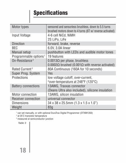
Specifi cations
Motor types
Input Voltage
DirectionBECManual setupProgrammable options1
On-Resistance 2
Rated Current 2
Super Prog. SystemProtections
Battery connections
Motor connectionReceiver connectionDimensionsWeight
sensored and sensorless brushless, down to 5.5 turnsbrushed motors down to 4 turns (6T w/ reverse activated)4-6 cell NiCd, NiMH2S LiPo, LiFeforward, brake, reverse 6.0V, 3.0A linearpushbutton with LEDs and audible motor tones19 features0.0013 per phase, brushless0.0002 brushed (0.001 with reverse activated)80A Continuous (160A for 10 seconds)Yeslow voltage cutoff, over-current,3over-temperature at 248°F (120°C)13AWG, Traxxas connector(Deans Ultra also included), silicone insulation13AWG, silicon insulationuniversal connector34 x 38 x 25.5mm (1.3 x 1.5 x 1.0”)83g
1 can set manually, or with optional DuraTrax Digital Programmer (DTXM1350)2 at 25˚C transistor temperature3 measured at semiconductor junction
Table 3
18
Optional Digital Programmer – DTXM1350*Please note that it is not necessary to have the optional programmer to use the basic features of the ESC.
The optional DTX Digital Programmer is a handheld device that allows the user to easily adjust parameters on the ESC. The programmer is small and lightweight making it highly portable, allowing the user to take it anywhere. Programming the ESC with this programmer is as easy as pushing a button. This programmer also allows the user to fi ne tune the adjustable features of the ESC and also gives the user the ability to view post-run data which is downloaded from the ESC such as average and maximum speed, maximum temperature and maximum current.
See your local retailer for details on how to get the DTX Digital Programmer.
19

Glossary1. Motor typeChanges the motor type. Sensored, Sensor-less or Brushed.
2. Battery typeChanges the battery type. NiCd/NiMH, LiPo, LiFe
3. Low Voltage CutoffThe DE10 ESC includes a low-voltage cutoff feature that stops motor rotation if the battery’s voltage drops too low. Users can have the ESC automatically set the low voltage cutoff in relation to the type of battery that is being used or the user can manually set the low voltage cutoff. Be sure that the battery is fully charged every time it is plugged into the ESC.
Note: When the battery type is changed the cutoff voltage is automatically changed. Make sure to select the correct battery type in advance prior to setting the cutoff voltage.
The automatic low voltage cutoff is displayed by both LED’s fl ashing once. When switching on the power the cutoff voltage is as follows:
LiPo: Higher voltage between 5.5V and 66% of startup voltage.
LiFe: Higher voltage between 5.0V and 67% of startup voltage.
NiMH/NiCD: higher voltage between 4.0V and 50% of startup voltage.
20

The low voltage cutoff can be manually adjusted between 3.0V~6.0V:
a. Both LEDs fl ash twice = 3.0Vb. Both LEDs fl ash three times = 3.5V c. …..d. Both LEDs fl ash eight times = 6.0V
4. Power Curve
Similar to exponential. This function makes the throttle high side operation quicker or milder.
5. Timing Advance
Zero degrees of advance is the lowest setting resulting in more torque, less rpm, least motor heat, but longest runtimes. Turning the timing up to the highest setting will do just the opposite
6. Acceleration
This is the time it takes the motor to change from the neutral position to max power. Slow reaction when setting lowest / max power when setting is the highest.
7. Start Power
This power is ONLY applied to the motor when motor starts operating from standby. Soft start when setting lowest / powerful start when setting highest.
8. Start Current Limiter
This current limitation is ONLY applied to the motor at standby when starting. If the trigger is moved to neutral then moved again to the forward position,
21
this function should be disabled. If the trigger stays at the neutral position for over 10 seconds, this current limitation should be activated. No current limitation if OFF is set.
9. Current Limiter
This current limiter is ONLY applied to the motor when motor is rotating to the forward direction. No current limitation if OFF is set.
10: Reverse
This turns the motor rotation to one-way or two-way. When Reverse is ON, the motor will operate forward and reverse. When OFF, the motor will operate in forward only.
11. Reverse Time Delay
A feature which allows the ESC to go into a fully proportional brake mode before going into reverse.
12. Neutral Width
Also known as Dead Band. Determines the amount of trigger travel between neutral and brake, and between neutral and throttle.
13. Motor Direction
This changes the direction that the motor turns.
14. Speed Mixing Brake
When speed mixing brake is 0% the brake feels like normal. As you adjust this percent up you can feel a difference in the way in which braking is applied to the motor. This speed mixing brake is only used 22

for sensored motors, and this is designed to deliver similar brake amount even if speed is changed.
15. ABS Brake
Pulse Brake. This is similar to pumping the brakes in a full size car.
16. Auto Brake
Also known as Drag Brake. This actually transforms the speed control’s dead band into brakes with a pre-determined frequency and value. This means any time the transmitter trigger is returned to the neutral position (dead-band), the brakes will be applied at the specifi ed frequency and percentage.
17. Minimum Brake
Minimum Brake is the amount of brake applied with the fi rst pulse of transmitter throttle input.
18. Maximum Brake
Maximum Brake is the total amount of brake applied when the trigger is in the full brake position.
19. Factory Setting
Returns all settings to factory defaults.
23

Troubleshooting GuideRx glitches or stutters during acceleration.
1. The required capacitors and diode are not installed or have broken on the brushed motor. Re-check the diode and all caps.
2. Rx signal is intermittent due to a large voltage drop during acceleration. Use either an external battery or a non-BEC receiver designed to be used with ESCs.
3. Rx mounted too close to ESC causing interference. Re-locate Rx away from ESC.
4. Check for faulty power connections.
5. Use of an AM radio system might be resulting in erratic signals. Use of an FM or 2.4 GHz radio system might be necessary.
Model runs slowly or has no acceleration.
1. The ESC is not set up properly. Repeat Step 6 on page 11.
2. Check for faulty battery and/or motor connections.
3. Tx is improperly adjusted. Repeat Step 3 on page 9.
Steering servo works but motor is dead.
1. For brushed motors, the brushes are hanging up, worn out, or motor is bad. Clean or replace brushes and check motor.
2. Check for faulty motor connections.
PROBLEM
PROBLEM
PROBLEM
24

Overheated motor or hot power plugs.
1. Motor is geared too high. Change to a lower gear setup.
2. Binding in the vehicle’s drive-train. Check to make sure nothing is interfering with the model’s drive-train.
3. The motor is shorted electrically. Check the motor for shorts and replace if necessary.
4. Check for faulty motor connections.
Motor runs backwards while forward LEDs are on.
1. Brushed motor is wired backwards. Re-check Step 2 on page 6.
2. A “reverse rotation” motor is being used. Replace with a forward rotation motor.
3. Brushless motor is improperly wired. Reverse any two of the connections going from the ESC to the motor.
Motor runs backwards when forward command is given, even though LEDs match the motor direction.
Move the Tx throttle reversing switch to the opposite position.
PROBLEM
PROBLEM
PROBLEM
25
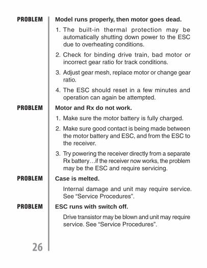
Model runs properly, then motor goes dead.
1. The built-in thermal protection may be automatically shutting down power to the ESC due to overheating conditions.
2. Check for binding drive train, bad motor or incorrect gear ratio for track conditions.
3. Adjust gear mesh, replace motor or change gear ratio.
4. The ESC should reset in a few minutes and operation can again be attempted.
Motor and Rx do not work.
1. Make sure the motor battery is fully charged.
2. Make sure good contact is being made between the motor battery and ESC, and from the ESC to the receiver.
3. Try powering the receiver directly from a separate Rx battery…if the receiver now works, the problem may be the ESC and require servicing.
Case is melted.
Internal damage and unit may require service. See “Service Procedures”.
ESC runs with switch off.
Drive transistor may be blown and unit may require service. See “Service Procedures”.
PROBLEM
PROBLEM
PROBLEM
PROBLEM
26
Service ProceduresESCs that operate normally when received by Hobby Services will be charged a minimum service fee and return shipping charges. Before sending your ESC in for service, it is important that you review the “Troubleshooting Guide” on this instruction sheet. The ESC may appear to have failed when other problems exist in the system – such as a defective transmitter, receiver or servo, or incorrect adjustments/installation.
* Hobby dealers are not authorized to replace ESCs thought to be defective.
* Do not cut the input wires of the ESC before sending it for service. A fee will be charged for cut wires which must be replaced for testing.
180 Day Limited Warranty - USA and Canada OnlyDuraTrax warrants this product to be free from defects in materials and workmanship for a period of 180 days from the date of purchase. During that period, we will repair or replace, at our option, any product that does not meet these standards. You will be required to provide proof of purchase date (receipt or invoice). If, during the warranty period, your ESC shows defects caused by abuse, misuse or accident, it will be repaired or replaced at our option, at a service charge not greater than 50% of the current retail list price. Be sure to include your daytime telephone number in case we need to contact you about your repair. This warranty does 27

not cover components worn by use, application or reverse voltage, cross connections, poor installation, subjection of components to foreign materials, any alterations to wires or tampering. In no case shall our liability exceed the original cost of the product. Your warranty is voided if:
● You apply reverse voltage to the ESC by connecting the motor battery backwards.
● You allow any wires to become frayed which could cause a short.
● You use more than the rated number of cells in the motor battery.
● You tamper with any of the electronic components.
● You allow water, moisture or any other foreign material onto the PC board.
Under no circumstances will the purchaser be entitled to consequential or incidental damages. This warranty gives you specifi c legal rights, and you may also have other rights which vary from state to state. If you attempt to disassemble or repair this unit yourself it may void the warranty.
For service to your DuraTrax ESC, either in or out of warranty, send it post paid and insured to:
Hobby Services (217) 398-00073002 N. Apollo Dr. Suite 1Champaign, IL 61822
E-Mail: [email protected] Address: www.duratrax.com
Entire Contents© 2010 Hobbico®, Inc.
Made in ChinaDTXM1300 Mnl
28