follow up cooperation study report on the project for...
TRANSCRIPT

The University of the South Pacific
The Republic of Fiji
Follow-up Cooperation Study Report
on
The Project for Upgrade of USPNet
Communication System
in
The Republic of Fiji
August 2016
Japan International Cooperation Agency
Relo Panasonic Excel International Co., Ltd
GL
JR
16-028

i
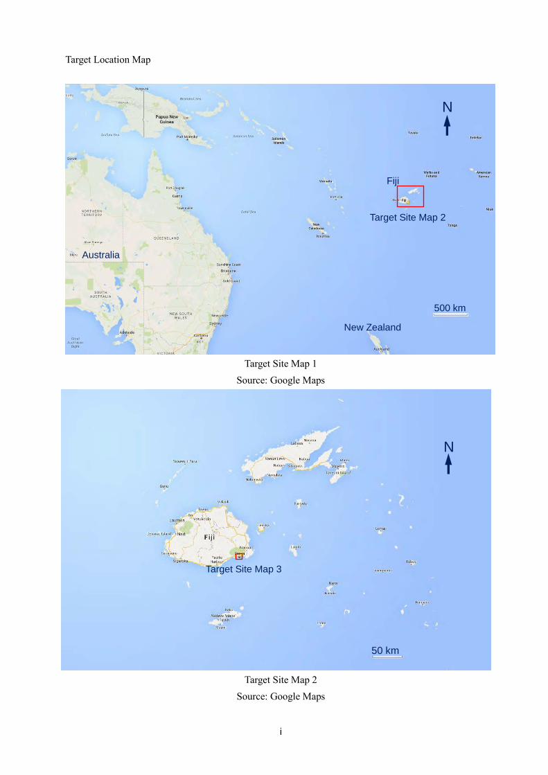
Target Location Map
Target Site Map 1 Source: Google Maps
Target Site Map 2 Source: Google Maps
Target Site Map 3
Target Site Map 2
Fiji
New Zealand
Australia
500 km
N
50 km
50 km
N

ii
Target Site Map 3 Source: Google Maps
Target Site Map 4 Source: Republic of Fiji USP ICT Center Improvement Plan,
Feasibility Study Report, December 2007
Target Site Map 4
Picture B Picture A
500 m
N

iii
USPNet Parabolic Antennae
USPNet Satellite Earth Station Photographer: Project worker (November 2015)
USPNet C Band Parabolic Antenna Photographer: Project worker (November 2015)
iv
Abbreviations ADB Asian Development Bank APT Asia-Pacific Telecommunity AARNet Australia’s Academic and Research Network ASP Application Service Provider ATH Amalgamated Telecom Holdings Limited AusAID The Australian Agency for International Development AZ Azimuth BPO Business Process Outsourcing C/P Counter Part DVC Deputy Vice Chancellor DRR Disaster Risk Reduction EL Elevation EOJ Embassy of Japan FBE Faculty of Business and Economics IC/R Inception Report ICT Information and Communication Technology ICTC Information and Communication Technology Center IT Information Technology IT/R Interim Report ITS Information Technology Services ITU International Telecommunication Union JICA Japan International Cooperation Agency NZaid New Zealand Agency for International Development TA Technical Assistance TAF Telecommunications Authority of Fiji TFL Telecom Fiji Limited USP The University of the South Pacific USPNet The University of the South Pacific Network
Table of Contents
Target Location Map ............................................................................................................................................. i
USPNet Parabolic Antennae ................................................................................................................................ iii
Abbreviations ...................................................................................................................................................... iv
1 Study Overview ............................................................................................................................................ 1
1.1 Background of the Study ...................................................................................................................... 1
1.2 Understanding of Challenges ............................................................................................................... 1
1.3 Purpose of the Study ............................................................................................................................ 1
1.4 Scope of the Study ............................................................................................................................... 1
1.5 Study Period, Team Members and Schedule ........................................................................................ 2
2 Results of the Study ..................................................................................................................................... 4
2.1 Present State of USPNet....................................................................................................................... 4
2.2 Present State of Donor Support to USP ............................................................................................... 7
2.3 Present State of USPNet Maintenance and Operation ......................................................................... 8
2.4 Present State of Target Equipment ......................................................................................................11
2.4.1 Beacon receiver .......................................................................................................................... 12
2.4.2 Antenna Control Unit (ACU) ..................................................................................................... 12
2.4.3 AZ Jack Assembly (Jack Assembly for Azimuth) ...................................................................... 13
2.4.4 EL Jack Assembly (Jack Assembly for Elevation) ..................................................................... 16
2.4.5 V-Beam (V-shaped Steel Material), Pedestal.............................................................................. 17
2.4.6 Main Reflector ............................................................................................................................ 17
2.4.7 Cable/Cable Ladder .................................................................................................................... 18
2.4.8 Present Condition of Equipment ................................................................................................ 20
2.4.9 Feasibility Study of Provisional Methods of Resolving Problems with Target Equipment, etc. 20
2.4.10 Summary of Target Equipment Malfunction Survey Results ..................................................... 21
2.4.11 Present Condition of Remote Stations ........................................................................................ 21
3 Approaches for Future Cooperation ........................................................................................................... 23
3.1 Three Options ..................................................................................................................................... 23
3.2 Considering Options .......................................................................................................................... 24
3.3 Results of Consideration .................................................................................................................... 25
3.4 Scope and Structure of New Grant Aid .............................................................................................. 25
3.5 New Grant Aid Relevance .................................................................................................................. 25
4 Recommendations for New Grant Aid ....................................................................................................... 27
4.1 Proposed Implementation Plan .......................................................................................................... 27
4.2 Implementation Details ...................................................................................................................... 29
4.3 Necessity of Engineer Dispatch ............................................................................................................... 29
4.4 Proposed Equipment Specifications ......................................................................................................... 30

4.4.1 Hub Station ................................................................................................................................. 30
4.4.2 Remote Stations .......................................................................................................................... 34
5 Recommendations to USP .......................................................................................................................... 37
5.1 Maintenance System ................................................................................................................................ 37
5.2 Budgetary Provisions ......................................................................................................................... 37
5.3 Maintenance Plan ............................................................................................................................... 37
Appendix 1: Questionnaire Responses ............................................................................................................... 40
Appendix 2: Minutes of Discussions.................................................................................................................. 41
1
1 Study Overview 1.1 Background of the Study
The University of the South Pacific (”USP”) is an international university jointly established by 12 island nations and regions (Fiji, Cook Islands, Kiribati, Marshall Islands, Nauru, Niue, Solomon Islands, Tokelau, Tonga, Tuvalu, Vanuatu and Samoa) with its main campus in the Republic of Fiji (“Fiji”). USP provides higher education services through USP Centers established in each country and region and its satellite communication-enabled distance learning network (“USPNet”). Japan implemented The Project for Upgrade of USPNet Communication System (grant aid that provided a maximum of 298 million yen) in 1998, and the project resulted in the installation of dedicated satellite communication network equipment (parabolic antennae, wireless equipment, etc.) for using VSAT small satellite earth stations in 2000 in Fiji to upgrade its conventional analog communication lines to digital.
Although a submarine cable was installed between Fiji and Tonga and went into service in 2013, satellite communication is a critical means of communication for nations in the Pacific region. The Laucala Campus of USP in Fiji is connected to USP Centers in partner countries and regions via USPNet, which uses satellite communication via C band and Ku band systems to offer satellite distance learning. Satellite communication systems are a critical element of USPNet. The Ku band systems were installed recently, but the C band systems - parabolic antennae and other satellite communication equipment in particular - were procured 15 years ago. The USP side maintains the systems and equipment, but the automatic tracking systems have malfunctioned and are unable to track satellites properly, making it difficult to provide stable communication over the systems.
1.2 Understanding of Challenges
The USP side has performed maintenance while increasing the speed of satellite communication and engaging in other efforts, and now antennae equipment and the like are the primary equipment of USPNet. However, the equipment was procured 15 years ago, and some of it has malfunctioned. Specifically, the automatic tracking system of the C band satellite communication system is broken, and the antennae must be positioned manually, presenting a challenge to the provision of a stable communication environment on USPNet. USPNet is critical to distance learning, which is a core function of USP. It is difficult for the USP side to help itself with this kind of technology; thus, urgent measures are required to extend the service life of the equipment and resolve the malfunction described above.
1.3 Purpose of the Study
The followings describe the purposes of this study.
① To study the condition of Target Equipment, etc. ② To confirm trends in information communication between island nations in the Pacific region ③ To confirm future plans, etc. for ICT in USPNet ④ To plan policies for follow-up cooperation
1.4 Scope of the Study
In this work, the following equipment is defined as the scope of the study.
2
① The scope of the study is the C band satellite communication system (including software; collectively “Target Equipment”) from among the satellite communication equipment used for USPNet and installed on USP Laucala Campus (the main campus of USP) during The Project for Upgrade of USPNet Communications System (a grant aid project).
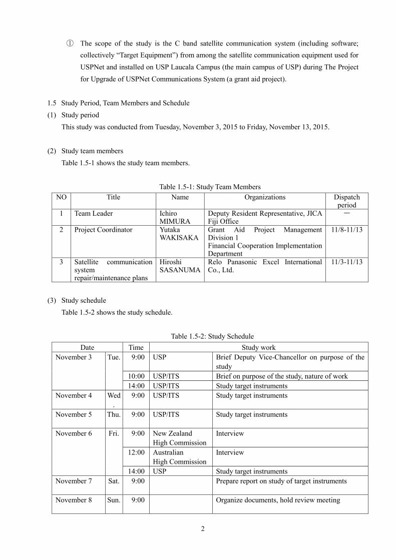
1.5 Study Period, Team Members and Schedule (1) Study period
This study was conducted from Tuesday, November 3, 2015 to Friday, November 13, 2015. (2) Study team members
Table 1.5-1 shows the study team members.
Table 1.5-1: Study Team Members NO Title Name Organizations Dispatch
period 1 Team Leader Ichiro
MIMURA Deputy Resident Representative, JICA Fiji Office
-
2 Project Coordinator Yutaka WAKISAKA
Grant Aid Project Management Division 1 Financial Cooperation Implementation Department
11/8-11/13
3 Satellite communication system repair/maintenance plans
Hiroshi SASANUMA
Relo Panasonic Excel International Co., Ltd.
11/3-11/13
(3) Study schedule
Table 1.5-2 shows the study schedule.
Table 1.5-2: Study Schedule Date Time Study work
November 3 Tue. 9:00 USP Brief Deputy Vice-Chancellor on purpose of the study
10:00 USP/ITS Brief on purpose of the study, nature of work 14:00 USP/ITS Study target instruments
November 4 Wed.
9:00
USP/ITS Study target instruments
November 5 Thu. 9:00
USP/ITS Study target instruments
November 6 Fri. 9:00
New Zealand High Commission
Interview
12:00 Australian High Commission
Interview
14:00 USP Study target instruments November 7 Sat. 9:00
Prepare report on study of target instruments
November 8 Sun. 9:00
Organize documents, hold review meeting

3
November 9 Mon.
JICA Fiji Office USP/ITS
Report on study of target instruments Discuss results of study of target instruments
November 10 Tue. 9:30
USP/ITS Discuss results of study of target instruments
November 11 Wed.
9:00
Organize documents, hold review meeting
November 12 Thu. 9:30
USP/ITS Discuss results of study of target instruments
November 13 Fri. 9:00 USP Report on the results of the study Sign minutes
14:00 JICA Fiji Office Report on the results of the study 15:00 Japanese embassy Report on the results of the study
(4) Main interviewees
Table 1.5-3 shows the main interviewees.
Table 1.5-3: List of Main Interviewees No Name Title Departments Organizations 1 Dr. Dilawar S Grewal Vice-President
(Administration) USP
2 Dr. Giulio Masasso Vice-President (Regional Campuses, Properties & Facilities)
USP
3 Prof. Derrick Armstrong Deputy Vice-Chancellor USP 4 Mr. Kisione W. Finau Director ITS USP 5 Mr. Neil Sharma Manager ITS USP 6 Mr. Ratu Marika T.T.
Qalomai Network Analyst ITS USP
7 Ms. Elizabeth C. Reade Fong Deputy University Librarian (Customer Services)
University Library
USP
8 Mr. Ian Thomson Senior Fellow e-Learning Faculty of Arts, Law & Education
USP
9 Mr Willy Morrel First Secretary Development (Fiji and Tuvalu)
New Zealand High Commission
10 Ms. Sheona McKenna Counsellor (Regional Health, Education and Gender)
Australian High Commission
11 Ms. Elizabeth Jitoko Senior Manager Regional Development
Australian High Commission
12 Takuji HANATANI Ambassador Embassy of Japan in the Republic of Fiji

4
2 Results of the Study 2.1 Present State of USPNet (1) History of USPNet development
USPNet is the network that comprises the backbone of communications between the 12 nations and regions with a stake in USP. It consists of network infrastructure, including a C Band satellite communication system, a Ku band satellite communication system and a submarine cable connection to Tonga. The C band satellite communication system went into service in 2000, and the Ku band satellite communication system was developed to build and improve the communications environment in areas the C band could not cover alone.
The Southern Cross Cable Network (SCCN), which connects Australia and New Zealand to the west coast of the United States of America via Fiji and Hawaii, went into service in 2000. Presently USPNet is connected to non-member countries by a carrier through SCCN. Within the region, the Tonga Cable, which connects Tonga and Fiji, was finished in 2013 and is used to connect a part of USPNet. Interchange Cable Network 1 (ICN1), which connects Fiji and Vanuatu, came online in 2014. Interchange Cable Network 2 (ICN2), which extends the connection from ICN1 to the Solomon Islands, is scheduled to begin service in 2016. The Solomons Oceanic Cable Network, which will connect the Solomon Islands to Australia, is also scheduled to begin operating in 2016. Unfortunately, due to high costs, the Tonga Cable is the only submarine cable USPNet currently uses for communication within the region. This means that satellite communication is a critical infrastructure for USPNet.
Table 2.1 and Figure 2.1 show the present state of submarine cables in the Pacific Island Region.
Table 2.1: Present State of Submarine Cables in the Pacific Island Region Submarine Cable Cable
Length Date of Completion
Landing Points
(1) PIPE Pacific Cable-1 (PPC-1)
6,900 km October 2009 Piti, Guam Madang, Papua New Guinea Sydney, Australia
(2) Interchange Cable Network 2 (ICN2)
3,000 km 2016 Honiara, Solomon Islands Luganville, Vanuatu Port Moresby, Papua New Guinea Port Vila, Vanuatu
(3) Interchange Cable Network 1 (ICN1)
1,238 km January 2014 Port Vila, Vanuatu Suva, Fiji
(4) Tonga Cable 827 km August 2013 Nuku'alofa, Tonga Suva, Fiji
(5) Southern Cross Cable Network (SCCN)
30,500 km November 2000 Alexandria, Australia Brookvale, Australia Hillsboro, Oregon, United States Kahe Point, Hawaii, United States Morro Bay, California, United States Spencer Beach, Hawaii, United States Suva, Fiji Takapuna, New Zealand Whenuapai, New Zealand
(6) Solomons Oceanic Cable Network
900 km Q2 2016 Auki, Solomon Islands Honiara, Solomon Islands Noro, Solomon Islands

5
Sydney, Australia (7) Australia-Papua New
Guinea-2 (APNG-2) 1,800 km 2006 Ela Beach, Papua New Guinea
Sydney, Australia Source: Submarine Cable Map (rows shaded in blue are cables in operation as of October 12, 2015)

6
Figure 2.1: Present State of Submarine Cables in the Pacific Island Region Source: Submarine Cable Map (as of October 12, 2015)
Hawaii
Guam
PNG Solomon Islands
Australia
New Caledonia
Vanuatu Fiji
Tonga French Polynesia
New Zealand
American Samoa
Samoa
(1)
(2) (3)
(4)
(5)
(5)
(6)
(7)

7
(2) Present state of USPNet USP Centers in each nation are connected to USPNet to provide online services such as distance
learning and library service. Below are overviews of each service. It is assumed, that interruptions to USPNet communications can cause major disruptions to classes, sharing of campus information, use of libraries and other university operations.
The present states of distance learning and library service are as follows.
Distance Learning Distance learning is the defining feature of USP. It began with streaming audio and packaged lectures,
and has developed to provide video streaming for teleconferencing. Presently video, audio and documents are available, and students use systems to respond by email, instant messaging and the like. Depending on the number of students and the teaching method, some courses focus on a blended mode that adds face-to-face interaction to online education.
Library Service
The main library on the Laukala Campus is digitized, with a Spydus System (a bibliographic search system) and others in operation. There are libraries on each campus throughout the region, but all students are able to access the main library from any campus through USPNet. The university is also connected to Australian academic network AARNet, providing access to the libraries of Australian universities and enabling users to perform bibliographic searches and obtain texts they need. Students can connect their PCs to Wi-Fi networks on campus to access USPNet, which enables them to connect to the main library, obtain the libraries they need and access other online environments including AAR-Net.
2.2 Present State of Donor Support to USP (1) New Zealand
New Zealand has a longstanding relationship with USP and is one of its main donors with donations in the millions of dollars. The New Zealand government has just embarked on a new three-year investment program with USP. Education, climate change and disaster risk reduction are among the 12 priority areas chosen for the project, which also include two new areas - agriculture and entrepreneurial spirit - that are the flagships of New Zealand’s cooperation with USP. ICT is also one of these priority areas.
Depending on the results of interviews, JICA will determine action methods, scopes of work, total expenses and other factors and then share information to enable the New Zealand government to confirm whether or not it can cooperate with the project.
(2) Australia
The Australian government entered a partnership agreement with USP lasting from 2014 to 2017 to provide support for USP’s Strategic Plan (2013-2018). Thus, the Australian government is of the opinion that there will be no provision of extra funding or new budgets for project-based activities.
Presently the Strategic Plan (2013-2018) includes Priority Area 4, Objective 13, which aims to “ensure that ICT provision adequately meets the University’s needs,” and 13.1 describes the goal to “review and
8
maximize the technical efficiency of the USPNet and IT infrastructure.” In terms of the budget for project-based activities, the study team was advised that, if USP is proactive
about the prioritization of projects under the Strategic Plan (2013-2018), it would be best to discuss prioritization of project-based activities within the funding range determined by Australia under the Strategic Plan (2013-2018) with the university.
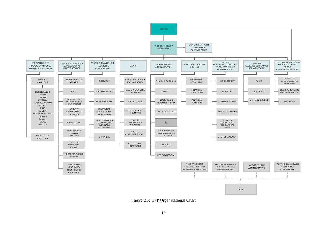
2.3 Present State of USPNet Maintenance and Operation (1) USPNet operation and maintenance implementation system
ITS, which reports directly to the USP Vice Chancellor and President, is responsible for the operation and maintenance of USPNet. Figure 2.3 is USP’s organizational chart.
USPNet operation and maintenance was performed by two people from the launch of service in 2000 to 2006 and by one person from 2006 to 2015. It has been performed by three people since 2015.
One person responsible for operation and maintenance since 2006 has an adequate understanding of satellite communication and sufficient technical capacity for operation and maintenance, but the two people added in 2015 are also working on the IP network. It is worth noting that one technician who performs operation and maintenance is assigned to each remote station.
Before the auto tracking malfunctioned in 2013, the antennae were painted once and moving parts on the antennae were lubricated regularly. However, since the auto tracking malfunctioned, neither the antennae nor their moving parts have been maintained.
(2) The state of document control
The manual and finished drawings prepared by the manufacturer (NEC) of the C band satellite communication system that went into operation in 2000 are stored together in the equipment shelter.
In addition, operation records of the transmission station and the state of each piece of equipment are kept and stored inside the shelter.
(3) State of maintenance implementation
Table 2.3 shows instruments that have been updated due to malfunction since operation began in 2000.
Table 2.3: Instruments Updated Due to Malfunction
Instrument Year updated Estimated costs High power amplifier (HPA) 2013 roughly 5,000,000 yen Low noise amplifier (LNA) 2013 roughly 1,000,000 yen
(4) USPNet-related budget
The budget related to USPNet is 2 MFJD (roughly 120 million yen for the 2015 budget) for employment costs, maintenance costs and line costs. USPNet uses 15MHz bandwidth and the line cost is 720,000USD a year (roughly 85 million yen).
(5) Present state of USPNet operation

9
In November 2013, the automatic tracking function stopped working, and the antennae have not been moved by motor since then. When the auto tracking malfunctioned, an alarm LED lit up and a beep sounded to alert technicians, who pressed down the alarm switch to turn off the beep.
Presently it is not possible to ensure as stable a connection as designed because the auto tracking function is not being used, but connections with remote stations have been established and a service environment is being provided for applications without issue.
However, the antenna cannot be moved by motor and thus must be put into “park position” (the antenna pointed at the sky, reducing its wind resistance to avoid damage) during cyclones, rendering it immobile and presenting a threat to safety.
Note that transmission is continuous and that an operation log is being kept.
10
Figure 2.3: USP Organizational Chart
DEPUTY VICE-CHANCELLOR
LEARNING, TEACHING
STUDENT SERVICES
VICE-PRESIDENT
ADMINISTRATION
PRO VICE-CHANCELLOR
RESEARCH &
INTERNATIONAL
DEANS
EXECUTIVE OFFICER
VC&P OFFICE
SUPPORT STAFF
ALUMNI RELATIONS
AUSTRALIA
AWARDS PACIFIC
SCHOLARSHIPS
(AAPS)
CROP ENGAGEMENT
COUNCIL AND
CENTRAL COMMITTEE
SECRETARIAT
CENTRAL RECORDS
AND ARCHIVES UNIT
MAIL ROOM
AUDIT
INSURANCE
RISK MANAGEMENT
DEVELOPMENT
MARKETING
COMMUNICATIONS
LIBRARIES
USP COMMERCIAL
MANAGEMENT
ACCOUNTING
FINANCIAL
OPERATIONS
FINANCIAL
PLANNING
VICE-PRESIDENT
REGIONAL CAMPUSES
PROPERTY & FACILITIES
POLICY & PLANNING
QUALITY
INSTITUTIONAL
RESEARCH & DATA
HUMAN RESOURCES
ITS
JAPAN-PACIFIC ICT
CENTRE & REGIONAL
ICT OUTREACH
FACULTY
APPOINTMENTS
COMMITTEE
FACULTY
ASSESSMENT BOARD
CENTRES AND
INSTITUTES
ASSOCIATE DEANS &
HEADS OF SCHOOL
FACULTY EXECUTIVE
COMMITTEE
FACULTY ASQC
FACULTY RESEARCH
COMMITTEE
SCHOLARSHIPS &
FINANCIAL
ASSISTANCE
COLLEGE OF
FOUNDATION
STUDIES
CENTRE FOR FLEXIBLE
LEARNING
CENTRE FOR
VOCATIONAL
&CONTINUING
EDUCATION
RESEARCH
GRADUATE AFFAIRS
USP INTERNATIONAL
INNOVATION
& KNOWLEDGE
TRANSFER/IP
PACIFIC CENTRE FOR
ENVIRONMENT &
SUSTAINABLE
DEVELOPMENT
USP PRESS
REGIONAL
CAMPUSES
COOK ISLANDS
KIRIBATI
LABASA
LAUTOKA
MARSHALL ISLANDS
NAURU
NIUE
SAMOA
SOLOMON ISLANDS
TOKELAU
TONGA
TUVALU
VANUATU
PROPERTY &
FACILITIES
UNDERGRADUATE
AFFAIRS
ASQC
STRATEGIC TOTAL
ACADEMIC REVIEW
( STAR) PROJECT
STUDENT
ADMINISTRATIVE
SERVICES
CAMPUS LIFE
VICE-PRESIDENT
ADMINISTRATION
EXECUTIVE DIRECTOR
FINANCE
DIRECTOR
DEVELOPMENT, MARKETING,
COMMUNICATIONS AND
ALUMNI RELATIONS
DIRECTOR
ASSURANCE, COMPLIANCE &
RISK MANAGEMENT
SECRETARY TO COUNCIL AND
MANAGER, COUNCIL &
CENTRAL
COMMITTEE SECRETARIAT
COUNCIL
VICE CHANCELLOR
& PRESIDENT
VICE-PRESIDENT
REGIONAL CAMPUSES
PROPERTY & FACILITIES
DEPUTY VICE-CHANCELLOR
LEARNING, TEACHING
STUDENT SERVICES
PRO VICE-CHANCELLOR
RESEARCH &
INTERNATIONAL
DEANS
11
2.4 Present State of Target Equipment Target Equipment is the C band satellite communication systems (including software) from among the
satellite communication equipment used for USPNet and installed on USP Laucala Campus (the main campus of USP) during The Project for Upgrade of USPNet Communications System (a grant aid project).
The USPNet satellite communication system comprises two parts: a C band system and a Ku band system. Both satellite systems are connected to LAN through shared baseband networks that modulate, implement line control, etc. Presently, both satellite systems are maintaining normal communications.
The C band system comprises a C band parabolic antenna, an antenna control and drive system, a receiving system and a transmitter. Since the system is maintaining a normal connection, the study team determined that there was nothing wrong with the present state of the transmitter. Therefore, the team focused its survey on the C band parabolic antenna, the antenna control and drive system and the receiving system.
Figure 2.4-1 shows the structures of the parabolic antenna, the antenna control and drive system and the receiving system. The larger the aperture of a parabolic antenna, the sharper the main beam and the higher the directivity. However, communication satellites move in figure-8 in shape orbits, mainly tracing a geostationary orbit due to the non-spherical nature of the Earth and other factors. Thus, large, high-directivity antennae must automatically track the moving communication satellites so that their beams face the satellites at all times. This is why large antennae are moved by motors to the proper elevation and azimuth angles to track satellites so that they can receive and maximize standard signals from the satellites.
Specifically, a parabolic antenna receives beacon signals from a communication satellite, and the low noise converter and frequency converter of the receiving system convert the signal to intermediate frequency L band to be received by the beacon receiver. The beacon receiver transmits the signal level it receives to the antenna control unit of the antenna control and drive system, which gives the motor control unit the amount of motor control to achieve the elevation and azimuth angles required to maximize the signal level and engages the motor of the AZ/EL jack assembly unit to move the antenna. This operation is repeated within a set amount of time, and the antenna is controlled in such a way as to maximize the level of beacon signals received. This is the tracking function. Interruptions to the tracking system likely indicate malfunctions in the parabolic antenna, receiving system or antenna control and drive system.

12
Figure 2.4-1: Structures of Parabolic Antenna, Antenna Control and Drive System, and Receiving System The study team conducted separate surveys for the receiving system and the antenna control and drive
system of the Target Equipment. The team confirmed visually whether proper lubrication, painting and grease charging were applied to the movable parts of the AZ/EL jack assembly unit of the antenna control and drive system, and also confirmed the state of corrosion and deterioration. 2.4.1 Beacon receiver
The beacon receiver does not have an alarm display; the study team confirmed normal reception when the “Lock” that indicates beacon signal reception illuminated.
The study team confirmed that, since the beacon receiver was operating normally, the low noise converter (mounted inside the center hub module on the rear surface of the antenna) at the input stage and the frequency converter mounted on the inside rack were operating normally.
2.4.2 Antenna Control Unit (ACU)
The team confirmed that the alarm LED lights up and that “AZ M Alarm” is displayed in the display area. They pressed down the alarm switch, but the display did not change, thus confirming that the AZ M Alarm was the only one the ACU was detecting.
Prior to the auto tracking malfunction in November 2013, figures on the display were recorded. The team compared these figures with display figures from the day of the study. Table 2.4-1 shows the details.
Table 2.4-1: ACU Display Angle/Level Display
November 2013 November 4, 2015 ⊿ AZ 352.1º 359.82º - 000.42º Roughly +8º EL 68.5º 318.04º Roughly +250º
Level 79 69.5 Roughly -10 A connection is established presently, so the following are likely explanations for the error in display
13
of AZ/EL angles.
① AZ/EL resolver (angle detector) is broken ② The ACU’s offset value configuration is incorrect ③ The ACU is broken and angle displays cannot be calculated correctly
According to the ACU manual, angle display X is derived from resolver reading R, that location’s
calculated value A and predetermined offset value O. The satellite is captured when skies are clear and the AZ, EL and POL (polarization) are adjusted to maximize the reception level. Once the antenna is in the optimal position,
X=A+(R-O) O=A+R-X
The offset value O is set according to the formula above. Therefore, since the display is displaying something at all, the third explanation is unlikely. The second explanation is plausible if someone doubled operations or the memory is damaged, but the state of operation is such that either of these is difficult to imagine. Doubling operations changes nothing unless the operation is in error; thus, the explanation that the resolver is broken is the most likely.
2.4.3 AZ Jack Assembly (Jack Assembly for Azimuth)
Rust has occurred on the shaft and reducer (the torque limiter coupling (decelerator) mounted between the AC motor and screw jack) of the AZ motor, which are stuck to the shaft support. The reducer is a device that transfers the appropriate amount of torque generated by the motor to the screw jack, and when it is stuck it is not transferring the torque from the motor.
Rust has also appeared on the motor terminals, and they continue to deteriorate. On the resolver (rotation angle detector)/ limit switch (position detector) module, the limit switch is disconnected, and this is likely the cause of the AZ M Alarm. The AZ jack does not have rust and is not deteriorating.
Overall, they are recognized, deterioration in parts, the sticking due to rust on the motor shaft and reducer and the disconnection on the resolver/limit switch module.
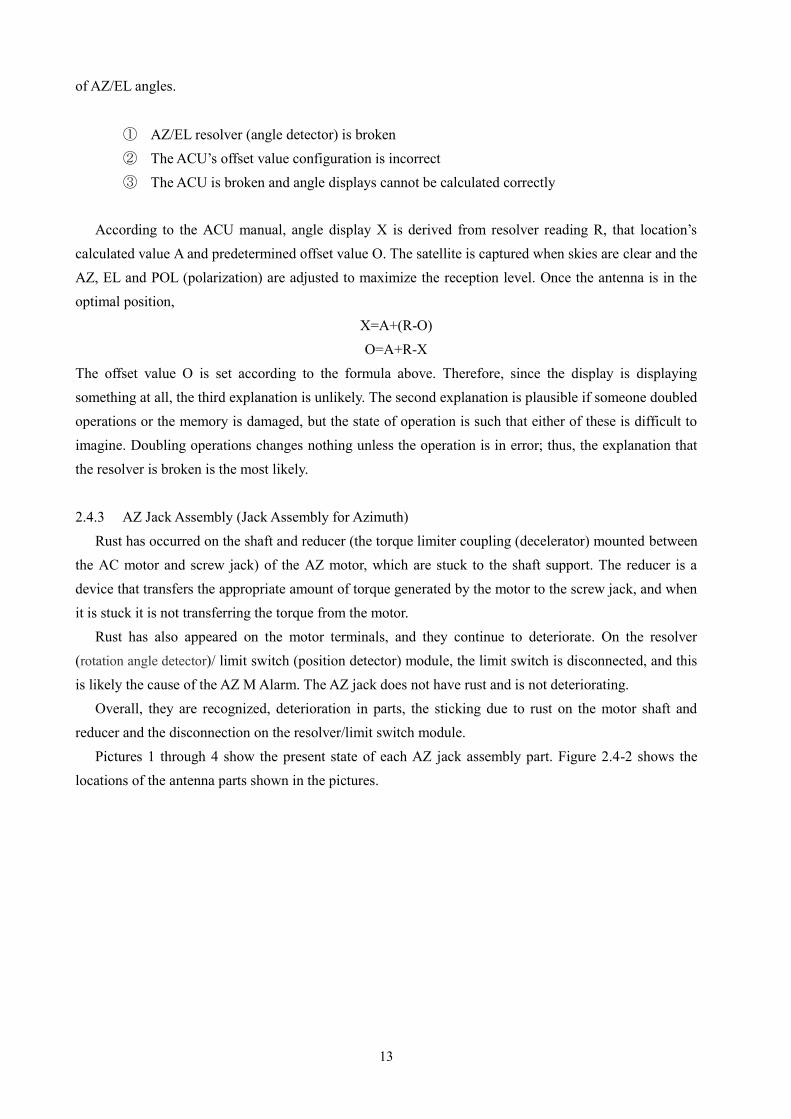
Pictures 1 through 4 show the present state of each AZ jack assembly part. Figure 2.4-2 shows the locations of the antenna parts shown in the pictures.

14
Figure 2.4-2: Locations of Pictured Antenna Parts
15
Picture 1: AZ (azimuth) Motor Shaft/Reducer (decelerator)
Picture 2: AZ Motor Terminals
Picture 3: AZ Resolver (azimuth rotation angle detector)/Limit Switch (position detector) Module (disconnected)
Picture 4: AZ Jack Shaft

16
2.4.4 EL Jack Assembly (Jack Assembly for Elevation) Rust has occurred on the EL (elevation motor reducer), and a chalky substance has made it stick in
place. The shaft and reducer sticking in place and refusing to rotate place an overload on the motor and lead to motor malfunction. If only the reducer is stuck, torque cannot be controlled, and too much torque can be transferred to the screw jack and the antenna cannot be moved with the motor. Rust has caused the material of the motor housing to curl, and its deterioration has progressed. It no longer protects the resolver (rotation angle detector)/ limit switch (position detector) module well, and an immense number of ants have invaded. The lack of protection allows humidity inside, which has caused rust damage to the resolver case. The EL jack screw had only a thin grease coating, and rust on the screw has caused it to deteriorate. In addition, the flange is rusted and has deteriorated significantly. The screw is stuck to the flange and has difficulty expanding and contracting normally.
Overall, they are recognized, the deterioration of the EL jack assembly, the motor shaft and reducer sticking due to rust and the chalky substance, damage to the resolver/limit switch module, and the screw deteriorating and sticking to the flange due to rust. It has progressed further than that of the AZ jack assembly (Jack Assembly for Azimuth).
Picture 5: EL (elevation) Motor Shaft
Picture 6: EL Motor Housing
Picture 7: Damage to EL Resolver (elevation rotation angle detector) / Limit Switch Module (position detector)

17
Picture 8: EL Jack Shaft
2.4.5 V-Beam (V-shaped Steel Material), Pedestal The pedestal that joins the V-beam (V-shaped Steel Material) that secures the EL jack assembly (Jack
Assembly for Elevation) is curling due to rusting, putting it at high risk of deteriorating strength as a supporting member.
Picture 9: V-Beam, Pedestal
Picture 10: Rust Causing Pedestal Curling
2.4.6 Main Reflector The main reflector is made of aluminum and thus has not rusted, but peeling paint and mold are
occurring throughout its surface. It has no effect on the instrument, but its location roughly 700 meters from the coast puts it as risk of salt damage and deterioration of surface materials after the salt-resistant paint peels away.

18
Picture 11: Peeling Paint on Rear of Main Reflector
Picture 12: Peeling Paint on Rear of Main Reflector/Outer Surface of Center Hub
2.4.7 Cable/Cable Ladder The cable ladder is stored in C-shaped housing that is corroded by rust and has deteriorated
significantly. The study team noted significant deterioration of the outer jackets of cables and waveguides.
Picture 13: Cable Ladder Location
Picture 14: Deterioration of Cable Ladder Housing Due to Rust

19
Picture 15: Significant Deterioration of Cable and Waveguide outer jackets

20
2.4.8 Present Condition of Equipment Table 2.4-2 shows the present condition of the Target Equipment.
Table 2.4-2: Present Condition of the Target Equipment No Name Maker Type No. Q’ty Condition Remarks
In door equipment HPA Rack
1 HPA NEC C7482J s/n5036 s/n5037
2 Not used Replaced to another unit by USP
2 HPA Path Selector NEC B4995G s/n5079
1 Not used Out of usage
3 GCE Amplifier Switchover NEC C3357A s/n6691
1 Not used Out of usage
MISC Rack 4 Motor Control NEC C5694B
s/n6029 1 Suspended Out of usage
5 Antenna Control Unit NEC D2544P
s/n6002 1 Suspended Out of usage by Alarm
6 Beacon Receiver NEC E4200B s/n6069
1 In operation 15years since installed
7 Down Converter NEC G2293B s/n5185
1 In operation 15years since installed
8 Up Converter NEC G2292B s/n5155
1 Not used Out of usage by system change
9 UIC NEC E2165E s/n5274
1 In operation 15years since installed
10 LNA Switch Control NEC Z0346B s/n145
1 Not used Out of usage by system change
GCE Bay Rack 11 GCE NEC C3357A
s/n6692 1 Not used Out of usage by system
change 12 Down Converter NEC G2293B
s/n5183 s/n5184
2 Not used Out of usage by system change
13 GCE NEC C3357A s/n6693
1 In operation 15years since installed
14 Up Converter NEC G2292B s/n5156 s/n5157
2 In operation 15years since installed
Outdoor equipment 15 AZ Screw Jack NEC 1 Damaged Rusted deeply 16 EL Screw Jack NEC 1 Damaged Rusted deeply 17 Mount Structure Assy NEC 1 In operation 15years since installed 18 Center Hub Assy NEC 1 In operation 15years since installed 19 Feed Mount Assy NEC 1 In operation 15years since installed 20 Back Up Structure NEC 1 In operation 15years since installed 21 7.6m C-band Main
Reflector Assy NEC 1 In operation 15years since installed
22 Sub Reflector Assy NEC 1 In operation 15years since installed 23 Cable Ladder wt. cable NEC 1 In operation 15years since installed
2.4.9 Feasibility Study of Provisional Methods of Resolving Problems with Target Equipment, etc.
Geostationary satellites trace a figure-8 in shape as they move in a geostationary orbit. Thus, the AZ/EL angles of large, high-directivity parabolic antennae are controlled with a function that

21
automatically tracks a satellite such that the main beam always faces the satellite. In its present state, the parabolic antenna’s angles are fixed and cannot track the satellite due to the malfunction of the automatic tracking function. The connection suffers when the satellite, which moves in figure-8 in shape orbit, move outside the focus of the main beam. The connection is worst when the satellite travels on the opposite side of the figure-8 in shape orbit and the antenna is fixed in a position furthest from the center of the orbit. To minimize the deterioration of the connection, the AZ/EL must be adjusted manually to maximize reception power at the point in time when the satellite passes through the center of the figure-8 in shape orbit. This is a provisional method of minimizing deterioration of the connection even when the satellite is furthest from the center of the orbit.
The study team determined from the results of the study that it is not possible to adjust the jack unit because it cannot be moved. Note that although the antenna’s auto tracking function does not work and the stability of the connection is below design standards, the equipment maintains a connection in its present state. The study team decided not to implement provisional adjustment as it is probably best to maintain the present state without forcing adjustments.
2.4.10 Summary of Target Equipment Malfunction Survey Results
The study revealed that the AZ jack assembly (Jack Assembly for Azimuth) and EL jack assembly (Jack Assembly for Elevation), which are outdoor instruments of the antenna control and drive system, have damaged, deteriorated components and must be replaced. In addition, other movable parts of the outdoor instruments may be stuck in place because they have not moved in two years. Overall, deterioration due to rust is progressing, and component service lives have expired in the 15 years since installation. Thus, there is no guarantee that parts that are not get replaced will continue to operate stably in the future.
Additionally, the service lives of the receiving system and the antenna control and drive system (indoor instruments) have expired in the 15 years since installation. Thus, it will be difficult to respond to malfunctions in the future. In particular, the beacon receiver, antenna control unit and other components connected to the AZ and EL jack assemblies are not standard pieces of equipment and will be difficult to use with replacement components.
2.4.11 Present Condition of Remote Stations
Eleven remote stations were built at the same time the hub stations were built. In addition, one remote station was built in 2006 and two more were built in 2015. The first 11 remote stations have been in service longer than 15 years, which is the period after which they are due for updating. In addition, the antennae installed outdoors have suffered salt damage due to the stations’ close proximity to the ocean. Table 2.4-3 shows the present condition of the remote stations.
Table 2.4-3: Present Condition of the Remote Stations
Earth station location (country/city) Antenna aperture
Power amplifier capacity
Year built Cooperating country/implementing
agency Marshall Islands Majuro 4.5 m 20W 2000 Japan
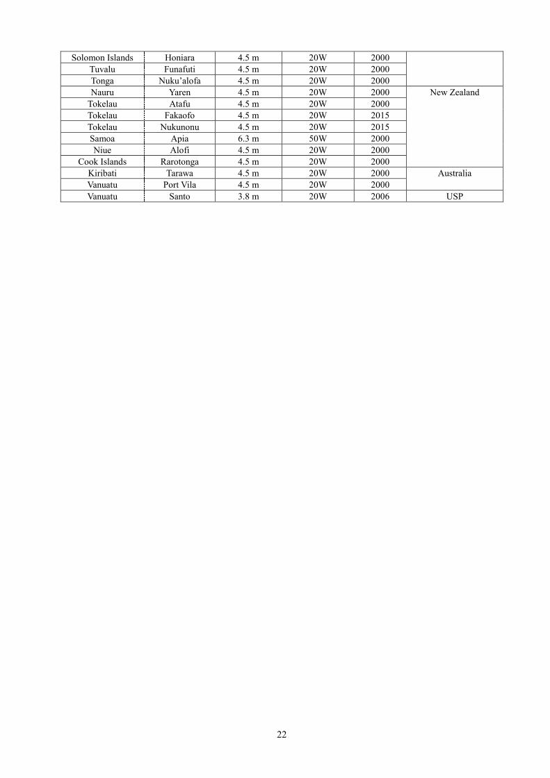
22
Solomon Islands Honiara 4.5 m 20W 2000 Tuvalu Funafuti 4.5 m 20W 2000 Tonga Nuku’alofa 4.5 m 20W 2000 Nauru Yaren 4.5 m 20W 2000 New Zealand
Tokelau Atafu 4.5 m 20W 2000 Tokelau Fakaofo 4.5 m 20W 2015 Tokelau Nukunonu 4.5 m 20W 2015 Samoa Apia 6.3 m 50W 2000 Niue Alofi 4.5 m 20W 2000
Cook Islands Rarotonga 4.5 m 20W 2000 Kiribati Tarawa 4.5 m 20W 2000 Australia Vanuatu Port Vila 4.5 m 20W 2000 Vanuatu Santo 3.8 m 20W 2006 USP

23
3 Approaches for Future Cooperation 3.1 Three Options
The study team agreed on three proposed options for repairing and updating the equipment with USP. Table 3.1 shows proposed options.
Table 3.1: Proposed Options
No. Method Outline 1 Replacement of AZ/EL jack
assembly (jack unit) with motor unit.
Replace only AZ/EL jack assembly with motor unit. Not replace other units of automatic tracking function (ACU, ADU, and Beacon Rx.).
2 Replacement of whole antenna with manual AZ/EL jack assembly without motor unit.
Operated the antenna manually. The lifetime of the system should last for 10 years with proper maintenance.
3 Replacement of whole antenna with automatic AZ/EL jack assembly with motor unit.
Replace whole antenna with motorized system with automatic tracking function. The lifetime of the system should last 10 years with proper maintenance.
The following are grounds for the selection of these options. The first option calls for the replacement of only the jack unit, which is the part that is presently
malfunctioning, and the continued use of the control unit and other existing equipment. This will restore the automatic tracking function, meaning it will be possible to ensure a stable, quality connection with no transmission and reception level deterioration even with respect to the orbital movement of the satellite. This option will also restore the power motor, enabling the antenna to be moved into the safe position (park position, pointing up at the sky) when cyclones and other disasters strike. With proper maintenance the jack unit can last another 10 years under this option, but the other equipment (the antenna unit, control unit, etc.) was installed 15 years ago and continues to deteriorate; it cannot be expected to last long because its design service life has already expired. Moreover, the USPNet C band system would have to be suspended during the work period (roughly four weeks) which, given the present state of USPNet services, renders this option unrealistic.
The second option takes into account the fact that a connection with a minimum stability has been established without the automatic tracking function, and calls for positioning the new antenna such that it can be adjusted to face the center of satellite orbit without installing the automatic tracking function. This will establish a stable connection as does the present state. The antenna unit in this option will last 10 years with proper maintenance, but it will be difficult to keep it safe during cyclones and other disasters. Thus, some uncertainty remains as to whether it can endure disasters and the like. In addition, since automatic tracking will not be engaged, the transmission and reception level will deteriorate and the quality of the connection will suffer with respect to the orbital movement of the satellite. The new antenna foundation would be built adjacent to the existing one, meaning the new system can be installed without interrupting the present system. Downtime can be minimized to roughly two weeks by moving from the present system to the new system before the adjustment and testing in the final stage of construction.
The third option calls for using the automatic tracking function with a new antenna. Thus, the antenna

24
and control unit can last for 10 years with proper maintenance, and the antenna can easily move to a safe position during cyclones and the like, so there is no worry about disasters. In addition, use of the automatic tracking function will make it possible to ensure a stable, quality connection with no transmission and reception level deterioration even with respect to the orbital movement of the satellite. The downtime would be held to a minimum as in the second option.
In addition, Severe Tropical Cyclone Winston caused major damage when it made landfall in northeastern Fiji in February 2016. Winston is the strongest cyclone on record in the southern hemisphere, with maximum wind velocity over one minute of 83 m/s (the Japan Meteorological Agency, which uses a 10-minute average, clocked winds at roughly 73 m/s). In extremely strong winds such as these, it is crucial to move parabolic antennae into safe positions (90º angle of elevation; pointing up at the sky) as quickly as possible, which requires power motor functions. Antennae with automatic tracking functions have such power motor functions.
3.2 Considering Options
The study team considered the priority of option implementation as shown on Table 3.1 in terms of the service lives of antenna units, electrical communication and control equipment, and in terms of cyclones and other meteorological conditions in Fiji.
(1) Antenna Units The jack components of antenna units become stuck in place due to rust and the like, making the
antenna units difficult to move. In addition, sensors and other components deteriorate rapidly. The strength of the supports has deteriorated because of curling of the metal parts due to rusting of the AZ Bearing-1 Assembly (the part where the AZ jack connects to the Pole Mount Assembly) of the Pole Mount Assembly (the post that supports the mirror surface of the antenna).
(2) Electrical Communication and Control Equipment
Presently there is no damage to the electrical control equipment of an antenna unit, but it is difficult for the manufacturer to provide maintenance because more than 15 years have passed since they were manufactured. As for the electrical communication equipment, one of the three low noise amplifiers that comprise the low noise amplification systems broke after this study was conducted. The low noise amplification systems comprise a 1:1 redundant system, and the broken system included this construction, but it was repaired by replacing the broken part with a spare part. There are no spare parts for the control units/low noise amplifiers that comprise the low noise amplifier systems. In addition, these systems are difficult for the manufacturer to maintain.
(3) Cyclones and Other Meteorological Conditions
In February 2016, which was after this study, the second-largest cyclone in recorded history (Severe Tropical Cyclone Winston) struck Fiji. Fortunately, the cyclone passed through northern Fiji, which meant that the earth station at the USP Laucala Campus, which is located in Suva in the southeastern part of the country, escaped direct exposure to the storm. Nonetheless, cyclones occur often here. When strong winds

25
hit, motors are used to point antennae at the sky to reduce wind pressure and increase their endurance. Motors are therefore critical for serving this function as well as for tracking satellites.
(4) Ranking of Options
Table 3.2 shows how these three options are ranked in light of the results of this study and these considerations.
Table 3.2: Ranking of Options
No. Method Overview Ranking 3 Replace entire antennae
installed on roofs. Use motorized AZ/EL Jack Assembly.
Replace whole antennae with motorized system and automatic tracking function. New systems should last 10 years with proper maintenance.
High
1 Replacement of AZ/EL jack assembly with motorized units.
Replace only motorizes AZ/EL jack assembly. Do not replace other units of automatic tracking system (ACU, ADU and Beacon Rx.).
Mid
2 Replace entire antennae installed on roofs. Use non-motorized AZ/EL Jack Assembly
Antennae will be operated manually. The systems should last for 10 years with proper maintenance.
Low
3.3 Results of Consideration In light of the importance of the hub station installed at the USP main campus to USPNet and the fact
that cyclones occur often in this part of the world, the study team chose Option 3 from Table 3.1. The study team obtained quotations for reference from several companies. This study revealed sweeping changes to the components envisioned when the follow-up cooperation was first requested, and a significant increase in their envisioned cost. Thus, the study team proposes the implementation of a new grant aid project.
3.4 Scope and Structure of New Grant Aid Over 15 years have passed since the present USPNet system was established in 2000, which is the
same amount of time as the service life for electrical equipment. In addition, antenna units may suffer salt damage due to their close proximity to the ocean. Thus, the study team proposes that the new grant aid project apply to the hub station and four remote stations built in 2000 for which Japan was responsible.
3.5 New Grant Aid Relevance
USP is dispersed across a wide area, and provides university education through USP Centers established in each of the member nations spread across the many islands of the Pacific region. USPNet is a core network that enables the distance learning, which is the defining feature of USP. In addition, USPNet which connects USP centers functions as a core communications network that provides library service and other student services. USPNet is an indispensable infrastructure for USP.
USP has helped its own cause by repairing minor issues and performing proper maintenance of USPNet, but the action required for the core of the communications system and the far-reaching implications exceed the limits of self-help and require the new grant aid project.

26
This survey revealed that the malfunctioning parts are central to USPNet and that the problems involve the satellite communication antennae at the hub station on the Laucala Campus. The antenna system was installed 15 years ago, and many parts - mainly the power motor parts but also movable parts, sensors and supports - have deteriorated and suffered damage. Both automatic tracking and manual antenna positioning have become impossible. In addition, the power amplifiers of the hub station transmission system control the remote stations, and although they are installed at the core station for transmitting distance learning content, they comprise only an active system; there is no standby system. In addition, although the low noise amplifiers of the receiving systems comprise a redundant system, over 15 years have passed since their installation, and one became damaged in February 2016 and was replaced with a cold standby system. It has become difficult to form a consistent, reliable system for sufficient communication using the USPNet hub station, which is the infrastructure for USP’s core services.
In addition, over 15 years have passed since the remote stations were installed, leaving them in the same condition as the hub station. The service lives of antennae and electrical equipment have passed, and there is a substantial risk of losing communication due to malfunctions. A communication blackout would make it impossible to take courses through distance learning, which would put both students and USP in a difficult situation.
The new grant aid is envisioned to be relevant as its scope would be the core of the communications system and have far-reaching implications, and because the action required exceeds the technical and budgetary limits of self-help.
As explained later in Section 5: Recommendations to USP, a maintenance plan focused on regular maintenance befitting a core system and plans to steadily update equipment after its design service life has expired will be critical to new grant aid.

27
4 Recommendations for New Grant Aid 4.1 Proposed Implementation Plan
Table 4.1 shows a proposed equipment procurement plan. After conducting field surveys sequentially starting from the hub station, antenna foundation will be
also constructed in order starting from the hub station. During this time, detailed designs will be created and a design review conference will be held locally. The equipment typically takes around four months to manufacture; including transportation to the sites, the equipment will arrive roughly five months after it is procured.
Assembly work and on-site coordination and testing will be performed in a series of construction work, starting at the hub station. Once the work at the hub station is complete, the system will be transferred from the active equipment. Once the communication testing at the existing remote stations is complete, assembly work and on-site coordination and testing will be performed sequentially at remote stations in a series of construction work. After installation at a given remote station is complete, the systems will be transferred from the active equipment, and communication with the hub station will be tested. Then, construction at that remote station will be complete. After the series of construction work at a given remote station is complete, the same work will be performed at the next remote station.
After construction is completed at all remote stations, general testing will be performed and the systems handed over.

28
Table 4.1: Proposed Equipment Procurement Plan
Month
Week 1st 2nd 3rd 4th 1st 2nd 3rd 4th 1st 2nd 3rd 4th 1st 2nd 3rd 4th 1st 2nd 3rd 4th 1st 2nd 3rd 4th 1st 2nd 3rd 4th 1st 2nd 3rd 4th 1st 2nd 3rd 4th 1st 2nd 3rd 4th 1st 2nd 3rd 4th 1st 2nd 3rd 4th 1st 2nd 3rd 4th 1st 2nd 3rd 4th 1st 2nd 3rd 4th 1st 2nd 3rd 4th
JICA Procurement Plan
-1 Public announcement
-2 Bidding
-3 Contract (contractor determined)
1
-1 Clearance surveys
-2 Basic installation surveys
2
-1 Detailed designs
-2 Design Review Meeting
3
-1 Equipment procurement
-2 Shipping/transportation
4
-1 Foundation work
-2 Equipment inspection H R1/2 R3/4
-3 Assembly work
-4 Laying of cables/waveguides R1 R3
R2 R4
-5 Instrument installation/mounting and wiring R1 R3
R2 R4
5
-1 System test H R1 R3
R2 R4
-2 Satellite acquisition H R1 R3
R2 R4
-3 Data measurement H R1 R3
R2 R4
-4 Satellite access test H R1 R3
R2 R4
6
-1 Joint inspection
-2 Handover/training
-3 Finished drawings
-4 Acceptance inspection/transfer
Work period H: Hub station
R1-R4: Remote Stations 1-4
Work in Japan
Field work
Other
H
Transportation (→to individual
countries)
H R1 R2 R3 R4
H
13 14 15 16
H
R1
R2
R3
R4
R4
Manufacturing
9 10 12117 85 6
R3
General tests/handover
H R1 R2
Field surveys
Design
Procurement/Transportation
Field work
Field coordination tests
Event
1 2 3 4

29
4.2 Implementation Details To ensure reliability and consistency of this critical part of network infrastructure, the electrical
equipment at the hub station will comprise an redundant system. Table 4.2 shows the target stations and their composition.
Table 4.2: Target Stations and Composition
Counterpart Station type Target facilities Fiji Hub
(1) 7.6-m parabolic antenna facilities
Antenna footing Motorized parabolic antenna with automatic tracking function Antenna control device Antenna motor Beacon receiver
(2) 1:1 redundant low noise amplifiers Low-noise amplifiers (total of three: active-standby, cold
standby) Redundant circuit Control units
(3) 1:1 redundant 80W SSPA units 80W SSPA units (total of three: active-standby with
up-converter, cold standby) Redundant circuit Control units
(4) Cable/waveguide circuit Cables to run between outdoor communication equipment and
communication equipment room Cables/waveguides to run between antennae and outdoor
communication equipment Dehydrator (Dry air supply system)
Marshall Islands Solomon Islands Tuvalu Tonga
Remote (Same for all stations) (1) 4.5-m parabolic antenna facilities
Antenna footing Manually-positioned parabolic antenna
(2) Low noise amplifier (outdoor equipment) Low noise amplifier (one active)
(3) 20W SSPA units (outdoor equipment) 20W SSPA unit (one with up-converter)
(4) Cable/waveguide circuit Cables to run between outdoor communication equipment and
communication equipment room Cables to run between antennae and outdoor communication
equipment Dehydrator (Dry air supply system)
4.3 Necessity of Engineer Dispatch
The installation of an antenna unit and foundation to improve the communication functions and execute the maintenance plans of the USPNet hub station for the new grant aid project requires high design standards. To ensure that these standards are met, the installation must be planned, assembly work

30
must occur on-site, the performance of individual equipment and whole systems must be tested, and a satellite access test must be passed. Therefore, the dispatch of engineers with advanced expertise will probably be necessary to implement these tasks.
Specifically, engineers are assumed to have the capacity to:
(1) Plan the installation of 7-m class satellite earth station parabolic antennae Plan cable system routes Measure skylines Plan antenna installation Plan antenna foundation
(2) Assemble and adjust 7-m class antennae, and conduct performance testing of satellite earth stations
Adjust main reflector mirrors Adjust sub-reflectors Measure antenna side lobe characteristics in the azimuth and elevation planes Measure high-frequency power Measure high-frequency and frequency deviation Measure high-frequency spectrum Capture satellites (target satellite: SES NSS-9)
- Installation location coordinates: 18.15º S, 178.45º E - Azimuth/elevation at installation location:
Elevation: 68.1º, Azimuth: 14.3º (east of true north) Conduct tracking performance tests
(3) Performance confirmation testing by satellite operator
Target channel settings - Transponder ID: GLL06/GLR06 - Start frequency (U/D): 6222.0/3997.0 MHz
Low-level unmodulated carrier transmission Polarization adjustment Operation level adjustment Modulated wave transmission
4.4 Proposed Equipment Specifications 4.4.1 Hub Station (1) Antenna Units
Structure These facilities comprise antenna mechanisms, feed system, motor control units and antenna
foundation. Antenna mechanisms comprise a main reflector, a sub-reflector, backup structures, a hub drum and antenna supports. Feed system comprise a feed horn device for transmitting or receiving the

31
prescribed electrical signals and converting them into the prescribed electrical signals, and waveguides for connecting to high power amplifier systems. Motor control units comprise motors for making the antennae automatically or manually track the desired satellite, and a control unit for controlling antenna steering angles. The control unit includes tracking devices for automatic tracking. Note that a dehydrator which supplies dry air into waveguides is used to dry the insides of waveguides. Antenna foundation is concrete base for mounting antenna supports.
Note that 1:1 redundant system of low noise amplifiers (LNAs) include LNAs, a power supply device and a control system. The 1:1 redundant system of LNAs with a power supply device is installed inside the hub drums. General Requirements
-1 Coating Rustproof coating; Color: White -2 Power voltage and variation Primary power voltage on the site is 200-240V.
compensation -3 Access satellite NSS-9 (183.0E) -4 Overall performance Satisfies earth station performance for SES NSS-9 satellite.
Passes SES NSS-9 performance confirmation testing. Mechanical Requirements
-1 Range of motion The antenna must have the following ranges of motion with the satellite direction at the center:
Azimuth: ±60º Elevation: 5-90º
The antennae must be able to move over the same range in cases other than AZ-EL mount.
-2 Wind resistance Antennae must be able to withstand winds of at least 55 m/s at any altitude, and winds of at least 88 m/s at altitude of 90º without breaking. In addition, during operation antennae must be able to withstand winds of at least 20 m/s, and maximum momentary wind speeds of at least 29 m/s.
Electrical Requirements -1 Frequency ranges Transmission: 5850-6425 MHz
Reception: 3625-4200 MHz -2 Antenna gain Transmission: at least 51.4 + 20 log (f/6) dBi
Reception: at least 48.5 + 20log (f/4) dBi (f is usable frequency, and the unit is GHz)
-3 Antenna noise temperature No higher than 40 K at 50º angle of elevation -4 Antenna side lobes Compliant with ITU-R S580 -5 Polarization Orthogonal circular polarization -6 Axial ratio 1.06 or lower -7 VSWR 1.3 or lower for transmission/reception -8 Transmission/reception isolation 75 dB or higher

32
-9 Number of ports Transmission: 2/Reception: 2; Total of 4 Motor Control Requirements
-1 Automatic tracking Has the capacity to automatically track SES NSS-9 satellite -2 Speed of antenna movement A speed fast enough to sufficiently track satellites even at a
steering elevation angle of 70º. -3 Locking function Has locking function -4 Remote control function Has the capacity for remote, manual movement of antennae -5 Local control function Has the capacity for power motor movement of antenna from
the area of the antenna -6 Manual operation function Has the capacity for manual movement of antenna from the area
of the antenna Other
-1 Shipping Containers Can fit inside a standard 40-ft container -2 Dehydrator system Installation of dry air supply system
Dehydrator system must have sufficient capacity for keeping the inside of waveguides dry at all times
-3 Measures against thunderstorm Antenna units must have lightning rods and be grounded damage
-4 Feed horn rain blower Installation of feed horn rain blower -5 Ladder and platform Installation of ladder and platform for maintaining rear sides of
a hub drum behind a main reflector (2) Low noise amplifier Electrical Requirements
-1 Frequency ranges Reception: 3625-4200 MHz -2 Noise temperature The noise temperature must be no higher than 40 K and satisfy
the required G/T. -3 Gain 60 dB or more -4 Dynamic range 60 dB or more -5 Gain frequency characteristics ±0.05 dB/MHz or less -6 Redundancy A 1:1 active-standby system that can be easily switched from
the equipment room next to the antenna unit. Must include one cold standby LNA.
-7 Other Alarms must be generated when abnormal situations arise. Installation must be such that it is easy to maintain the insides of hub drums on the rear sides of antennae.
(3) High Power Amplifiers Electrical Requirements
-1 Output frequency range Transmission: 5850-6425 MHz
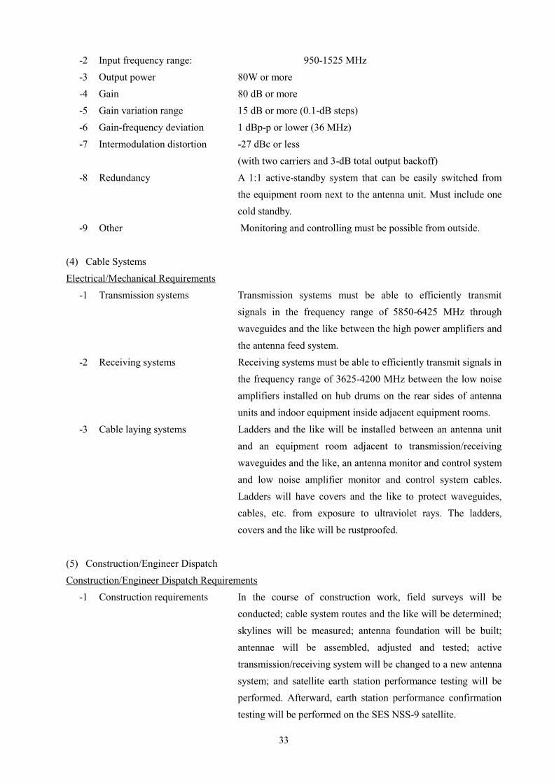
33
-2 Input frequency range: 950-1525 MHz -3 Output power 80W or more -4 Gain 80 dB or more -5 Gain variation range 15 dB or more (0.1-dB steps) -6 Gain-frequency deviation 1 dBp-p or lower (36 MHz) -7 Intermodulation distortion -27 dBc or less
(with two carriers and 3-dB total output backoff) -8 Redundancy A 1:1 active-standby system that can be easily switched from
the equipment room next to the antenna unit. Must include one cold standby.
-9 Other Monitoring and controlling must be possible from outside. (4) Cable Systems Electrical/Mechanical Requirements
-1 Transmission systems Transmission systems must be able to efficiently transmit signals in the frequency range of 5850-6425 MHz through waveguides and the like between the high power amplifiers and the antenna feed system.
-2 Receiving systems Receiving systems must be able to efficiently transmit signals in the frequency range of 3625-4200 MHz between the low noise amplifiers installed on hub drums on the rear sides of antenna units and indoor equipment inside adjacent equipment rooms.
-3 Cable laying systems Ladders and the like will be installed between an antenna unit and an equipment room adjacent to transmission/receiving waveguides and the like, an antenna monitor and control system and low noise amplifier monitor and control system cables. Ladders will have covers and the like to protect waveguides, cables, etc. from exposure to ultraviolet rays. The ladders, covers and the like will be rustproofed.
(5) Construction/Engineer Dispatch Construction/Engineer Dispatch Requirements
-1 Construction requirements In the course of construction work, field surveys will be conducted; cable system routes and the like will be determined; skylines will be measured; antenna foundation will be built; antennae will be assembled, adjusted and tested; active transmission/receiving system will be changed to a new antenna system; and satellite earth station performance testing will be performed. Afterward, earth station performance confirmation testing will be performed on the SES NSS-9 satellite.
34
Antenna foundation will be constructed with enough strength to fully support the designated wind pressure load of 7-m class parabolic antennae. After performance confirmation testing is complete, completion drawings (in English), operation manuals (in English) will be created and used to explain operation to people in charge of operation on the USP side.
-2 Engineer dispatch requirements Engineers must have experience in planning, assembling and testing 7-m class satellite earth station parabolic antennae, and implementing satellite earth station performance testing and performance confirmation testing by satellite operators.
4.4.2 Remote Stations (1) Antenna Units Structure
A remote station facilities comprise antenna mechanisms, feed system and antenna foundation. Antenna mechanisms comprise a main reflector, a sub-reflector, backup structures, hub drums and antenna supports. It must be possible to point antennae in the direction of the desired satellite. Feed system comprise a feed horn device for transmitting or receiving the prescribed electrical signals and converting them into the prescribed electrical signals, a low noise block converter, solid state power amplifier with up converter and cables for connecting to wireless facilities. A dehydrator which supplies dry air into waveguides is used to dry the insides of waveguides. Antenna foundation is concrete base for mounting antenna supports.
Note that components include a low noise block converter, a solid state amplifier and a feed system. These devices are installed on the antenna. General Requirements
-1 Coating Rustproof coating; Color: White -2 Power voltage and variation Primary power voltage on the site is 200-240V.
compensation -3 Access satellite NSS-9 (183.0E) -4 Overall performance Satisfies earth station performance for SES NSS-9 satellite.
Passes SES NSS-9 performance confirmation testing. Mechanical Requirements
-1 Range of motion The antenna must have the following ranges of motion with the satellite direction at the center:
Azimuth: ±60º Elevation: 5-90º
The antennae must be able to move over the same range in cases other than AZ-EL mount.
-2 Wind resistance Antennae must be able to withstand winds of at least 67 m/s at
35
any altitude without breaking. In addition, during operation antennae must be able to withstand winds of at least 44 m/s.
Electrical Requirements -1 Frequency ranges Transmission: 5850-6425 MHz
Reception: 3625-4200 MHz -2 Antenna gain Transmission: at least 46.6 + 20 log (f/6) dBi
Reception: at least 43.4 + 20 log (f/4) dBi (f is usable frequency, and the unit is GHz)
-3 Antenna noise temperature No higher than 30 K at 60º angle of elevation -4 Antenna sidelobes Compliant with ITU-R S580 -5 Polarization Orthogonal circular -6 Axial ratio 1.06 or lower -7 VSWR 1.3 or lower for transmission/reception -8 Transmission/reception isolation 75 dB or higher -9 Number of ports 2 transmission/receiving ports
Other -1 Shipping Containers Can fit inside a standard 20-ft container -2 Dehydrator system Installation of dry air supply system
Dehydrator system must have sufficient capacity for keeping the inside of waveguides dry at all times
-3 Measures against thunderstorm Antenna units must have lightning rods and be grounded Damage
(2) Outdoor equipment Electrical Requirements
-1 Frequency ranges Transmission: 5850-6425 MHz Reception: 3625-4200 MHz
-2 Transmitted power Transmitted power amplifier output will be at least 20W. -3 Noise temperature The noise temperature of low noise block converter will be 60
K or lower. -4 Interface with indoor equipment The equipment will be connected to transmission and receiving
systems through intermediate frequencies. -5 Length of cables connecting Cables can be extended as long as 80 m without problems.
indoor and outdoor equipment (3) Cable Systems Electrical/Mechanical Requirements
-1 Cables connecting indoor and Cables will connect to transmission and receiving systems outdoor equipment through intermediate frequencies, and cable length can be
extended up to 80 m.

36
(4) Construction/Engineer Dispatch Construction/Engineer Dispatch Requirements
-1 Construction requirements In the course of construction work, field surveys will be conducted; cable system routes and the like will be determined; skylines will be measured; an antenna foundation will be built; an antenna will be assembled, adjusted and tested; active transmission/receiving system will be changed to a new antenna system; and satellite earth station performance testing will be performed. Afterward, earth station performance confirmation testing will be performed on the SES NSS-9 satellite. An antenna foundation will be constructed with enough strength to fully support the designated wind pressure load of 4.5-m parabolic antennae. After performance confirmation testing is complete, completion drawings (in English), operation manuals (in English) will be created and used to explain operation to people in charge of operation on the USP side.
-2 Engineer dispatch requirements Engineers must have experience in planning, assembling and testing 4.5-m satellite earth station parabolic antennae, and implementing satellite earth station performance testing and performance confirmation testing by satellite operators.

37
5 Recommendations to USP 5.1 Maintenance System
Given regional characteristics, satellite communication will doubtlessly continue to be the principal communication infrastructure, underscoring the importance of a satellite communication system for USPNet. It is best to establish sufficient systems and technical levels, and for operation and maintenance to be executed faithfully under a long-term maintenance plan.
Presently at USP, there are a total of three people assigned to this task - one core engineer responsible for the hub station operation and maintenance, and two assistant engineers. USP Centers serve as remote stations, and major USP Centers have an average of three technical staff members, one of whom is responsible for operation while the other two focus on maintenance. At minor USP Centers, one person is responsible for operation and maintenance.
Training consists mainly of on-the-job training during scheduled maintenance and maintenance performed as necessary. Staff members from each USP Center gather at the hub station to receive on-the-job training during scheduled maintenance, which is performed every three to four years at the hub station. Hub station Engineers visit USP Centers once each year for on-the-job training during maintenance performed as necessary.
An overall USPNet maintenance system exists, but it focuses completely on the one core Engineer assigned to the hub station at Laucala Campus. Given the importance of satellite communication to the network, the technical levels of the two assistants should be improved in order to strengthen the system.
To improve their technical levels, they can (1) take classes on satellite communication structure and (2) measure data (RF/IF level spectrums, carrier frequencies, output level diagrams, etc.) from actual systems periodically. Having the assistants improve their skills should improve their technical capacity and familiarity with satellite communication and lead to more stable operations and faster responses to problems.
5.2 Budgetary Provisions
As of 2015, 200 million FJD (roughly 120 million yen) is allotted annually to expenses for operations and maintenance. The budget is allocated to employment costs, satellite line costs and maintenance. In these, the C-Band satellite line costs are $720 thousand USD at 15MHz a year (roughly 85 million yen). Presently, a total of 15 stations (one hub station and 14 mini hub and remotes stations) operate in USPNet’s C band system. Twelve stations were installed in 2000, one was added in 2006 and two were installed in 2015.
In addition to the hub station and four remote stations, one mini-hub station and seven remote stations built in 2000 are due for updating. The mini-hub station has a 6-m class parabolic antenna, and the seven remote stations have 4.5-m class parabolic antennae. These stations have each been in operation for 15 years, and their design service lives have expired. Thus, they require scheduled budget preparation and updating executed by USP.
5.3 Maintenance Plan
Maintenance of the antennae and other machinery must be implemented in a planned fashion. This

38
would maintain optimal system conditions and enable stable operation. In particular, automatic satellite tracking functions can be installed onto 7-meter class parabolic antennae. The antennae move to automatically track a satellite at set intervals, and only specific parts of screw jacks and gears move. Those parts can be damaged by friction if they are not properly lubricated. Thus, grease charging at regular intervals is an important maintenance task. Each USPNet satellite earth station is installed close to the ocean. Thus, periodically repainting is also important. Keeping up with these tasks can ensure the long-term operation of the equipment.
Table 5.1 shows an example of a parabolic antenna maintenance plan.

39
Table 5.1: Example of Parabolic Antenna Maintenance Plan
Year
Task Quarter 1 2 3 4 1 2 3 4 1 2 3 4 1 2 3 4 1 2 3 4 1 2 3 4 1 2 3 4 1 2 3 4 1 2 3 4 1 2 3 4 1 2 3 4 1 2 3 4 1 2 3 4 1 2 3 4 1 2 3 4
REPAINTING Repainting every seven years ● ●
LUBRICATION Grease charge every six months ● ● ● ● ● ● ● ● ● ● ● ● ● ● ● ● ● ● ● ● ● ● ● ● ● ● ● ● ●
Grease Charge (Worm Case) Gearbox grease charge every five years ● ● ●
Grease Charge (Reducer) Reducer grease charge if necessary
BEARINGS Grease charge every six months ● ● ● ● ● ● ● ● ● ● ● ● ● ● ● ● ● ● ● ● ● ● ● ● ● ● ● ● ●
AZ BEARING Grease charge every five years ● ● ●
TIGHTENING BOLTS AND NUTS Bolt tightening once a year ● ● ● ● ● ● ● ● ● ● ● ● ● ●
Protection Bellows Inspection every three months ● ● ● ● ● ● ● ● ● ● ● ● ● ● ● ● ● ● ● ● ● ● ● ● ● ● ● ● ● ● ● ● ● ● ● ● ● ● ● ● ● ● ● ● ● ● ● ● ● ● ● ● ● ● ● ● ● ● ● ●
REPAINTING Repainting every seven years ● ●
Hub Station
Remote Stations
13 14 157 8 9 10 11 1261 2 3 4 5

40
Appendix 1: Questionnaire Responses
1 Organizational System-1 Describe the USPNet operating system.
-2 Describe the USPNet personnel system.
-3 Explain the USPNet annual operating budget (costs for personnel; equipment expansion, maintenance and repair; and spare partpreparation).
2 Activity status-1 Describe year-to-year trends in class participation over USPNet from the beginning of USPNet to the present.
-2 Describe year-to-year trends in the number of students at each USP Center over USPNet from the beginning of USPNet to the present.
3 Operation status-1 Describe the state of downtime (the number of hours per day, total number of days per year) at the USPNet Fiji HUB.
-2 Describe whether or not alternative methods exist for downtime at the USPNet Fiji HUB.
-3 Describe the state of downtime (the number of hours per day, total number of days per year) at each USP Center.
-4 Describe whether or not alternative methods exist for downtime at each USP Center.
-5 Describe whether or not operation logs (records of transmission and end of transmission) are kept at the USPNet Fiji HUB.
4 Operating system-1 Number of operators at the USPNet Fiji HUB
-2 Number of operators for USPNet at each USP Center
-3 What kinds of methods are used to detect alarms, failures and other problems at the USPNet Fiji HUB?
-4 What kinds of methods are used to detect alarms, failures and other problems with USPNet at each USP Center?
5 Maintenance system-1 How many people work in maintenance (maintenance-only personnel, and people who also work as operators) at the USPNet Fiji HUB.
-2 How many people work in maintenance (maintenance-only personnel, and people who also work as operators) for USPNet at each USPCenter?
-3 Does updated documentation for the USPNet system (operation manuals, maintenance manuals, system configuration diagram) exist at theUSPNet Fiji HUB and each USP Center?
-4 Is technical training for operation and maintenance of USPNet implemented? If so, how often?
In larger campuses in the Region, we have an average of 3 tchnical staff where one is often the operator and the other 2 are often the maintenance -only persons. In smaller
campuses or centers, we normally have only 1 technical staff who both covers for Maintenance and also as an Operator
Yes Documentation and As-Builts information are available for these. In fact, we have a system where our designs, changes in design, modifications etc are well
documented and reflect the lastest changes on the ground
Yes Technical Training is done both as a planned and scheduled Annual Routine Maintenance Schedule (ARMS) and on an Ad-Hoc basis where each Regional remote
Campus site personnel gets on On-the Job hands on training. ARMS are often done every 3 - 4 years with all Operators converging in the main Campus in Laucala, Suva
whilst the Ad-Hoc schedules occur often every year anually with site visits to our regional sites
Yes Operations Logs and records on status of Equipment etc are kept in USPNet Fiji Hub
1)- Proprietry iDirect Monitoring System which is known as iMonitor (2) SNMP data monitoring platforms via PRTG (3) Nagios Alerts
At the Fiji Hub, we have 1 principal core Technical person who is the Operator with backup from 2 others. For Maintenance purposes, we have a pool of the same 3 people
from above
As with -1 above, when the Hub is affected due to Sun Interefernce in March and Sept periods, ALL other Regional Campues connected via our Satellite Network does get
affected. The number of downtimes per remote site varies as well i.e when the Sun Outage period also affects the independent countries apart from Fiji and also not
mentioning loca Power Supply issues on site if and when there is a power outage. But measures and controls are in place where we have UPS units and Power conditioners
to protect and prevent intermittent Power outages at these site unless there is a pro-longed outage which their local UPS and Generators cannot sustain over this prolonged
period. Average downtime periods for each Regional Campus or Center is therefore 15 mins per day for 10 days a year for Sun Outage and approx 30mins to 1 hour a day
for at least days a Year for Power outages
As mentioned in -3 above, alternative methods for reliable Power sources are addressed in having UPS and Generators being intalled in all regional sites. Unfortunely
there is no alternative or redundancy mechanism in place for Sun Interference Outages
We have a team and they share responsibilities.
One each
(1)- Proprietry iDirect Monitoring System which is known as iMonitor (2) SNMP data monitoring platforms via PRTG (3) Nagios Alerts
All the Satellite Hardware situated at the Hub are in full redundancy mode meaning each Primary equipment has a fail-over secondary when and if needed. UPS Power is
also provided together with a Generator so Power is not an issue or concern for downtime at the Hub
USPNet Questionnaire
The USPNet is a privately owned ICT system/network within USP which comprises mainly of a Satellite Infrastructure encompassing the vsat South Pacific Is member
countries which are part of USP. This infrastructure is essential in providing critical access to Teaching, Learning and Online data access for both Staff and Students on
demand. USPNet is the life-line of our Regional Wide Area Network (WAN) infrastructure. It comprises of the Hub which is based in Laucala Campus, Suva Fiji with
around 20 Regional Campuses and Centers using the iDirect Evolution platform. This platform is further shared by using C-Band and Ku-Band footprints across the
Pacific. The Outdoor unit and partial Indoor unit mechanisms at the Hub utilises the NEC Antenna System together with the necessary Satellite Signalling Equipment
needed in standard Earth Stations
The USPNet is operationally being managed by the IT Services under the Director's Office, who then delegates Operations and maintenance thru the Enterprise Systems &
Networks Infrustructure and the User Services Departments within IT Services
Director IT Services is responsible for the Operating and Recurrent budgets for USPNet inclusing Personnel, equipment procurement, maintencance etc..
The Operating and Recurrent budgets for USPNet inclusing Personnel, equipment procurement, maintenance are part of ITS budget. In total ITS has a total budget
2 millions per years and that include personnel, bandwidth and maintenance. Every year, we submit a proposal for capex expenditures.
Trends really have been increasing with more interactions now needed in Real Time applications like Video Conferencing and Tutorials, Submission of Moodle
assignments Online, more Wireless and BYOD usage within our Campuses thus straining more use of Bandwidth Capacity for USPNet. The University is now into Online
instruction and Learning which further increases the value and need of an efficient ICT infrustructure
USP continues to have increasing Student enrollments in each Campus and as such demands on the usage of USPNet resources has always been critically essential
(1) In March and September each year there is intermittent downtime of services due to scheduled Sun-Interference caused by Sun Outage on NSS9 and IS18 Satellites that
USP is leasing from our Satellite providers. This amounts to approx 15mins in total a day for approx 15 days (2) Important scheduled updates also are required to Update
the Hub and this equates to 30mins a day about 3 times a year
Respondent Name - Marika Qalomai Date: Friday 30th Oct 2015
Affiliation - USPNet Engineer

41
Appendix 2: Minutes of Discussions

42

43

44
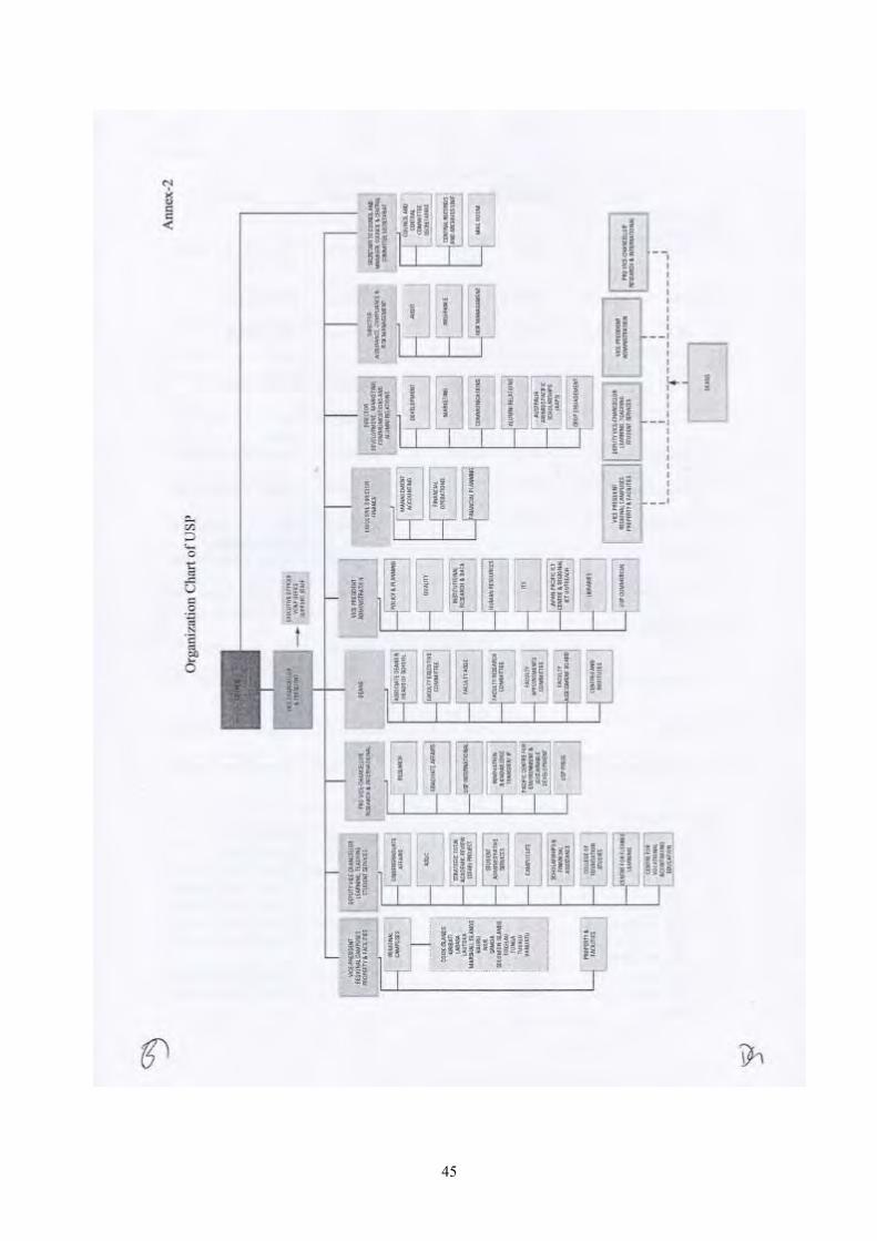
45

46

47