folded plate biography summary girder … capacity of the top plate. the cyclic test (test c1) was...
TRANSCRIPT

FOLDED PLATE GIRDER BRIDGE SYSTEM: A NEW
HORIZON FOR SHORT SPAN
BRIDGES
ATOROD AZIZINAMINI
BIOGRAPHY
Atorod Azizinamini, Ph.D., P.E. is Chair of the Department of Civil and Environmental Engineering at Florida International University’s College of Engineering and Computing. He is also director of Accelerated Bridge Construction University Transportation Center (ABC-UTC) at FIU, the first federally-funded entity focused on developing technology and methods to improve bridge building.
Azizinamini came to FIU in 2011 from the University of Nebraska-Lincoln, where he was a Distinguished College of Engineering Professor and the Director of National Bridge Research Organization. He was the principal investigator of the project SHRP2 R19A, leading to the development of “Guide for Design of Bridges for Service Life” for enhancing the service life of new and existing bridges.
He has received a number of awards, including the American Institute of Steel Construction (AISC) Special Achievement Award for his development of Folded Plate Steel Bridge Technology. He has published more than 200 technical papers covering many aspects of structural engineering. He worked as consulting engineer for six years before joining academia.
SUMMARY
Almost 45% of the bridges in U.S. bridge inventory are less than 60 ft in length. Most are simple spans located on county roads. Many of these short-span bridges are either structurally deficient or functionally obsolete and need to be replaced. This paper provides description of steel bridge alternative that provides an economical alternative for short span bridges (less than 60 ft), that is especially suited for application in the case of Accelerated bridge construction.
The Folded Plate Girder Bridge System (FPGBS), offers the same advantages as closed steel box girder, except that the opening in the bottom allows easy inspection of the system. Elimination of any bracing (internal or external or top lateral bracing), significantly enhances the service life and reduces the cost. The lowest fatigue category for the FPGBS is Category B.
Page 1 of 10
FOLDED PLATE GIRDER BRIDGE SYSTEM: A NEW HORIZON FOR SHORT SPAN BRIDGES
Introduction Almost 45% of the bridges in U.S. bridge inventory are less than 60 ft in length. Most are simple spans located on county roads. Many of these short-span bridges are either structurally deficient or functionally obsolete and need to be replaced. It is essential to develop alternatives that are economical, can be constructed using light construction equipment, and have long service life with minimal maintenance. This paper provides an overview of the work leading to development and application of the Folded Plate Girder Bridge System (FPGBS) that is providing an economical alternative for short span bridges.
Description of Folded Plate Girder Bridge System Folded Plate Girder Bridge System (FPGBS), offers an economical solution for many of the nation's bridges with maximum span lengths up to 60 ft. The system consists of a series of standard shapes that are built by bending flat plates into inverted tub sections using a press break. Figure 1 shows a fabrication process for a typical folded plate girder.
Figure 1. Fabrication of folded plate girder using a press break machine
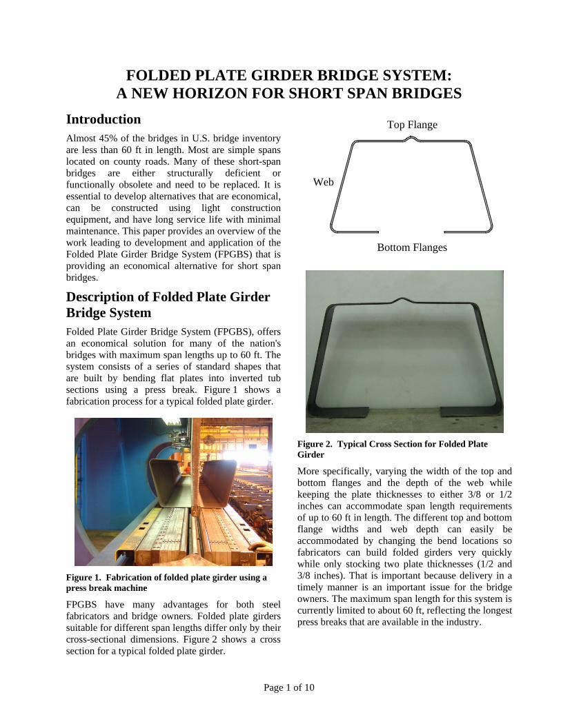
FPGBS have many advantages for both steel fabricators and bridge owners. Folded plate girders suitable for different span lengths differ only by their cross-sectional dimensions. Figure 2 shows a cross section for a typical folded plate girder.
Figure 2. Typical Cross Section for Folded Plate Girder
More specifically, varying the width of the top and bottom flanges and the depth of the web while keeping the plate thicknesses to either 3/8 or 1/2 inches can accommodate span length requirements of up to 60 ft in length. The different top and bottom flange widths and web depth can easily be accommodated by changing the bend locations so fabricators can build folded girders very quickly while only stocking two plate thicknesses (1/2 and 3/8 inches). That is important because delivery in a timely manner is an important issue for the bridge owners. The maximum span length for this system is currently limited to about 60 ft, reflecting the longest press breaks that are available in the industry.
Top Flange
Bottom Flanges
Web

Page 2 of 10
Advantages of Folded Plate Girder Bridge System The shape of the cross section for the Folded Plate Girder Bridge System has several key advantages in its design and construction. Following are brief descriptions of some of the advantages.
The inverted tub shape produces a very stable bridge girder configuration that does not require internal or external cross frames for either local or global stability. A typical box section needs top lateral bracing, during construction and during replacement of deck, while folded plate girder does not. Figure 3 shows a 46 ft. long folded plate girder.
Figure 3. 46 ft. Long Folded Plate Girder
Casting the deck on top of folded plate girder could use conventional construction equipment and practices. The top flange of the folded plate girder is wide enough (about 25 in. to 35 in.) to serve as a work platform. That alone can reduce many construction hazards associated with workers walking on girders during construction. Figure 4 shows conventional formwork that can be used to prepare for casting the concrete deck. Because of the torsional stiffness of the folded plate girder, there is no need for providing internal or external bracing during construction.
Perhaps the major advantage of folded plate girder is the opening from the bottom side that allows inspection of the girder. Experience with closed utility poles (even galvanized) and closed box sections indicates that over time debris and moisture find ways to penetrate inside the box and accumulate and can result in significant reduction in service life of the bridge as a system. For longer span bridges the depth of a closed box is large enough to enter inside and inspect and clean if needed. Folded plate
girders provide the same characteristics as that of a closed box with the advantage of being able to inspect the inside. The opening on the bottom side of the folded plate also allows passing the utility lines, if needed. Figure 5 shows the bottom view of a 46 ft. long folded plate. Several alternatives are available to prevent bird nesting inside the box.
Figure 4. Conventional formwork for casting concrete deck
Galvanizing the FPGBS is a very good option for corrosion protection. Hot dip galvanizing can provides more than 75 years of service life at a very economical cost.
Folded Plate Girder Bridge System in Modular Form Recently, the trend within the bridge construction industry has been toward reducing construction activities on the bridge site and eliminating the interruption to traffic. The FPGBS can be constructed using conventional construction techniques as well as using principles of Accelerated

Page 3 of 10
Figure 5. Bottom view of 46 ft. Long folded plate girder
Bridge Construction (ABC). In the case of conventional construction procedures, readily available construction equipment could be used to build the formwork for casting the concrete deck as shown in Figure 4.
An alternate and perhaps better approach when using the FPGBS to construct short-span bridges is to use prefabricated, pre-topped elements, where each unit consists of a folded plate girder with deck cast on the top. Several (usually four) of these units (pre-topped folded plate girder) could then be transported to the field, placed side by side and joined together to complete the bridge construction. Figure 6 shows a pre-topped folded plate girder unit ready for shipping to job site.
Figure 6. Pre-top folded plate girder
Brief Summary of Research Work Leading to Development of Folded Plate Girder Bridge System An extensive amount of experimental, numerical and analytical work was performed to comprehend performance of FPGBS and develop design aids. This section provides brief summary of experimental, numerical and analytical studies carried out.
Experimental Tests Experimental testing consisted of conducting 9 tests using 6 test specimens. Figure 7 shows the generic shape of a folded plate specimen and Table 1 gives the dimensions of the different specimens that were used in testing. Note that the Trap Width and Trap Height dimensions refer to an idealized trapezoid along the plate midline without corner radii
As indicated from Table 2, tests carried out included testing folded plate girders without any deck (constructability test) and cyclic, shear and ultimate load tests on folded plate girders with deck on the top.
.

Page 4 of 10
Figure 7. Generic Test Specimen Cross Section
Table 1. Specimen Geometry
Height Width Top
Flange Bottom Flange Thickness
Side Length Opening
Trap Height
Trap width
Ridge Height Angle
Bend Radius
Yield Stress
Units in in in in in in in in in in degree in ksi Label A B C D E F G H J K L R
Sp
ecim
en
A 24.75 45.47 30 10 0.375 20.7 20.72 24.38 46.42 0* 75 2 65 B 24.75 45.47 30 10 0.375 20.7 20.72 24.38 46.42 0* 75 2 65 C 24.75 45.47 30 10 0.375 20.7 20.72 24.38 46.42 0* 75 2 65 D 24.88 43.85 28.78 11.8 0.375 21.87 16.50 24.50 44.50 1.0 75 1.5 50 E 24.88 43.85 28.78 11.8 0.375 21.87 16.50 24.50 44.50 1.0 75 1.5 50 F 25.0 43.64 27.92 11.1 0.5 20.71 16.5 24.50 44.50 1.0 75 2.0 50
*No ridge in top flange
Table 2. Summary of Testing Program
Test ID Specimen Length* Type Stiffener @ load point Deck Comments
A1 A 41’ Constructability No No B1 B 41’ Constructability Yes No C1 C 41’ Cyclic No Yes C2 C 41’ Ultimate No Yes D1 D 46’ Constructability Yes No E1 E 46’ Ultimate No Yes Galv. E2 E 22’ Shear No Yes Galv. E3 E 22’ Shear No No Galv. E4 E 22’ Shear Yes No Galv. F F 46’ Modular Deck No Yes
*Length specifies the span length from centerline of support to centerline of support
BJ
C
AF
L R
GD
H
K
E

Page 5 of 10
The initial tests were carried out on test specimens without a ridge on the top (k dimension equal to zero). Constructability tests indicated that folded plate girders with flat top flanges demonstrated pre-mature buckling of top flange. As a result the ridge was introduced in the top flange to increase compression capacity of the top plate.
The cyclic test (Test C1) was conducted to comprehend the performance of folded plate girder with pre-topped deck, under repeated traffic loads. The test setup is shown in Figure 8. The test specimen was subjected to total of about 7.5 million load cycles, as indicated in Table 3
Figure 8. Composite Test Setup
Table 3. Cyclic Load Summary
Load Stage Cycle Numbers
Load (kips)
Cycle Rate (Hz)
1 0 to 302797 60 1.4 2 3027989 to 5115,287 60 1.2 3 5115,287 to 7179,071 72 1.0
Table 4 provides the stiffness of the systems at various cycle numbers. The stiffness of the system was calculated by dividing the applied load by the deflection. As seen, there was very little change in stiffness throughout the cyclic testing, which indicates there was no progressive softening or failure of the specimen.
Table 4. System Stiffness
Initial Cycle
#1,794,770 Cycle
#3,589,540 Cycle
#7,179,071 116.1571kip
s/in 117.0952kip
s/in 114.1837kip
s/in 114.0183kip
s/in
Ultimate Load Test Specimen E was a galvanized specimen with a stiffening ridge along the top flange as shown in Figure 9.
Figure 9. Specimen E – Cross Section
Figure 10 shows the basic load deflection plot obtained from the test. The load is the total load applied to the girder and the deflection data is obtained from midspan.
Figure 10. Test E1 – Load versus Displacement
Also shown in Figure 10, is the theoretical plastic moment capacity of the cross section for the test specimen using measured material properties. As indicated from figure 13, specimen exhibited significant amount of displacement ductility before failing.
Shear Testing Ultimate load testing of test specimen E, consisted of applying a concentrated load at the mid-span of the bridge. The failure of the test specimen E was in the form of crushing of the concrete at mid-span. Once ultimate load testing of test specimen E was
Composite Folded Plate Test E1
0
50
100
150
200
250
300
0 2 4 6 8 10 12
Deflection (in)
Lo
ad (
Kip
s)
Theoretical Plastic Capacity

Page 6 of 10
complete, the specimen was cut in half near mid-span where the failure had occurred. One half of the test specimen E was used to carry out shear test.
Figure 11 shows the test set up for shear test E2. Figure 16 shows the resulting applied load versus the deflection at the point of load application. Specimen was able to carry very high load (600 kips) before failure.
Figure 11. Test E2 – Load Configuration
Figure 12. Test E2 – Load Deflection
Development of Design Aids Significant amount of work was carried out to develop design aid for use of Folded Plate Girder Bridge System (FPGBS) in practice. This included development of standard sections, customized distribution factors and design sheet for each standard cross section.
Table 5 shows the standard shapes that were developed. The name specifies the width (W) and
height (H) of the defining trapezoid as well as the clear opening (O) between the bottom flanges. The weight (Wt), moment of inertia about the strong bending axis (Ixx), and location of neutral axis relative to the bottom of the bottom flange (NA) is given for plate thicknesses (t) of 3/8-inch and 1/2-inch.
Table 5. Standard Shapes
Name t
(in) Wt (plf)
Ixx (in4)
NA (in)
W36H16O16 3/8 99 1260 9.2 1/2 133 1485 9.3
W36H18O16 3/8 103 1615 10.2 1/2 138 1895 10.3
W36H20O16 3/8 107 2015 11.1 1/2 143 2360 11.2
W40H20O16 3/8 117 2315 11.1 1/2 157 2710 11.1
W40H24O16 3/8 125 3390 12.9 1/2 167 3945 12.9
W44H24O16 3/8 135 3825 12.9 1/2 181 4450 12.9
W40H28O16 3/8 133 4680 14.7 1/2 178 5420 14.7
W40H32O16 3/8 141 6180 16.4 1/2 188 7135 16.4
W44H32O18 3/8 149 6750 16.7 1/2 194 8080 16.7
W40H34O16 3/8 145 7015 17.2 1/2 199 7785 17.3
W44H34O20 3/8 150 7430 17.8 1/2 200 8545 17.9
In order to use conventional design procedures the amount of load distributed to each girder in a multi-girder system must be evaluated. Simplified distribution relationships exist for many common structure types, some of which could be argued are applicable to the folded plate girder system. A study was carried out to establish a more exact distribution factor for the folded plate girder system. A power fit method, similar to that used in the AASHTO LRFD Specifications approximate analysis table, was applied to the results. The resulting equations are given in
Table 6. An additional suite of analyses was performed investigating skew and found that the equations given by the current AASHTO LRFD Specifications to account for skew – both for flexure and shear – yields conservative results under all conditions.
Load Deflection
0
100
200
300
400
500
600
700
0 0.2 0.4 0.6 0.8 1 1.2
Deflection (in)
Lo
ad (
Kip
s)
P1
Solid Marker = Prior to UltimateHollow Marker = After UltimateDotted Line = Unloading

Page 7 of 10
Table 6. Distribution Factor Equations
Interior Exterior
Fle
xure
Single
35.0
3
7.06.0
0.121025.0
s
g
Lt
K
L
SSLever Rule
Multiple 2
40
36 L
SgSL
30.126
115.1
s
gSLML Lt
Kgg
Skew Adjustment
Factor
Sh
ear
Single
35.0
3
4.08.0
0.121225.0
s
g
Lt
K
L
SSLever Rule
Multiple 2
25
45 L
SgSL 07.0 SLML gg
Skew Adjustment
Factor tan
0.122.01
3.03
g
s
K
tL
Where: 2gg AeInK with
D
B
E
En
Variables and Units are consistent with the approximate distribution factor tables contained in the AASHTO LRFD Bridge Design Specifications.
S = Girder Spacing (ft)
L = Span Length (ft)
ts = Slab Thickness (in)
de = distance from the exterior web of exterior beam to the interior edge of curb or traffic barrier (ft)
Finite element analysis was also used to evaluate the transverse bending moment in the deck slab. The primary recommendation is that the slab be designed utilizing the empirical design method as specified in AASHTO LRFD 9.7.2. In lieu of empirical design, the traditional method specified in AASHTO LRFD 9.7.3 may be used. The loading values may be obtained from AASHTO LRFD Table A4-1. For the case of negative bending, the girder spacing value contained in the table shall be taken as the distance between the webs of adjacent girders, which may be calculated based on the dimensions of the defining trapezoid. For the case of positive bending, the girder spacing
value contained in the table shall be taken as the girder centerline spacing. Use of the centerline spacing accounts for the torsional flexibility of the girder since an individual web near midspan will not provide vertical restraint in the same way that it does near a support.
Design Data Sheets For each of the 11 standard sections, a design data sheet was prepared that could assist the designer to select the desired section and contains the following information:
A dimensioned drawing of the section
5.15.025.0
3tan
0.1225.01
L
S
tL
K
s
g

Page 8 of 10
Sectional Properties such as Area, Moment of Inertia, etc.
Non-Composite (Dead Load) Capacity
Nominal Ultimate Composite Moment Capacity
Composite Moment of Inertia
Composite Live Load Deflection
Non-Composite Dead Load Deflections
Kg
Eccentricity Reduction Factor
A sample data sheet is shown in Figure 16 at the end of this paper and further details are provided in the following paragraphs. The specified section parameters such as trapezoid width and height are repeated for reference. The total plate width is the un-folded width of the plate used to form the section. This value includes 0.5 inches to account for the ridge along the top flange. The listed area and weight of the section is obtained from this total plate width. The calculated section properties such as Ixx, Sx, rx, and Kg ignore any stiffening ridge along the top flange.
The predicted plastic and yield moment capacities of the non-composite section are calculated assuming a yield strength of 50 ksi. These values do not include any stiffening ridge on the top flange. The maximum moment values listed for different span lengths are the moments correspond to the maximum values obtained from the finite element analyses. Note that all of these values are unfactored
The ultimate moment capacity values are calculated based on AASHTO LRFD 6.10.7.1.2, which governs composite compact sections in positive flexure. The base strength is the plastic moment capacity of the section, which is then reduced based on the relative location of the neutral axis with respect to the total depth of the section. Sections where the neutral axis is located high in the section behave more ductile and are allowed to utilize a greater portion of their plastic moment capacity. The plastic moment capacity of the section was obtained using an idealized trapezoid shape (ignoring the radius in the corners). The plastic neutral axis was found considering a balance of forces. The
concrete stress in the compressive region was taken to be 0.85f’c. The flange pad (haunch) thickness is the distance from the top of the top flange (ignoring any ridge) to the bottom of the deck. The effective width of the slab is limited to six times the slab thickness beyond the edge of each web (i.e. beff<=TopWidth + 12ts). Combinations that violate this requirement are left blank.
The composite moment of inertia does include the radius in the corners of the section and any stiffening ridge is ignored. The composite moment of inertial values are then used to calculate the composite live load deflection due to a single HL-93 truck (without lane load) positioned for maximum effect. The truck has not been distributed, reduced, or amplified in any way.
The non-composite dead load deflection for various slab widths and thickness at different span lengths are provided. The deflection due to the bare steel is listed at the bottom of the table. To obtain the total deflection, the deflection due to the bare steel must be added to the deflection due to the slab. When the total deflection exceeds sqrt(L/1200), the value is printed in red type. This is not a hard limitation but rather a warning that excessive deflections may occur if not prevented by means such as shoring.
The eccentricity reduction value modifies the non-composite strength when the applied loading is eccentric to the centerline of the girder and is an expression fit to data obtained from finite element analysis. The eccentricity reduction value is not dependent upon the section properties and therefore identical for each sheet. However, having the table in close proximity of the non-composite capacities will be useful. Note that there is no need to use eccentricity reduction value if shored construction is used when casting the deck.
Demonstration Projects The first structure built using the folded plate bridge system was a 46 foot stream crossing in Uxbridge, Massachusetts. Figure 13 shows the second of four pre-topped units being lifted into place. A photo of a single unit during transport was seen in Figure 6.

Page 9 of 10
Figure 13. Construction of First Folded Plate Bridge
Once all units were in place, a concrete diaphragm was cast at the ends of the girders, shown in Figure 14, along with the longitudinal closure regions. Finally, a bitumous riding surface was applied.
Figure 14. Girder Ends and Closure Region
A second demonstration project is currently underway in Boone County, Nebraska. The construction details of this structure will vary slightly in that the end wall will be an integral part of the pre-topped unit, as shown in Figure 15.
Figure 15. Integral End Wall Detail
Conclusions This paper provides an overview of a new steel bridge system that is proving to be very competitive with other material types for short span bridges. The form of the system to be used in accelerated construction form is superior to concrete alternate bridges, since the total weight of one girder plus deck is much less than pre-topped concrete girders (about three times less), allowing use of light cranes on construction sites. Further, the folded plate girder bridge system in modular form does not experience creep and shrinkage, eliminating the field problems observed with side by side pre-topped concrete girders.
This paper provides a brief list of major research topics carried out to allow field application of the folded plate girder bridge system. The development of the folded plate girder bridge system is a result of research at the University of Nebraska-Lincoln. Ongoing research and development work is aimed at extending the use of the folded plate girder bridge system to longer and continuous bridge systems. Additional information on folded girder bridge systems contact Dr. Atorod Azizinamini at [email protected].

Page 10 of 10
Figure 16. Sample Data Design Sheet