fokker dvii 250 slow flyer arf - blade - #1 by design
TRANSCRIPT

SpecificationsWingspan: 34.0 in (865mm)Wing Area: 310 sq in (19.4 sq dm)Length: 26.5 in (672mm)Weight w/o Battery: 7.20–7.50 oz (204–212 g)Weight w/Battery: 8.50–9.00 oz (240–255 g)
Fokker DVII 250 Slow Flyer ARFAssembly Manual

2 E-flite Fokker DVII 250 Slow Flyer Assembly Manual
Using the Manual
This manual is divided into sections to help make assembly easier to understand, and to provide breaks between each major section. In addition, check boxes have been placed next to each step to keep track of its completion. Steps with a single circle () are performed once, while steps with two circles ( ) indicate that the step will require repeating, such as for a right or left wing panel, two servos, etc.
Remember to take your time and follow the directions.
Contents of Kit/Parts LayoutReplacement Parts
EFL1976 Wing SetEFL1977 FuselageEFL1978 Tail SetEFL1979 CowlingEFL1980 Wheel SetEFL1981 Landing GearEFL1982 Lower Gear SpreaderEFL1983 Wing StrutsEFL1984 Machine Gun SetEFL1985 Hardware pack
Introduction
Loved by the pilots who flew it and feared by those who flew against it, the Fokker DVII is regarded by many as the greatest fighter of WWI. E-flite brings this Great War legend to life with this remarkable foamy slow flyer that comes out of the box loaded with scale details. Details like molded machine guns, accurately modeled interplane struts, a dummy Mercedes engine and an intricately detailed cooling grille, just to name a few. Even the vibrant trim scheme that comes pre-printed on the foam is an authentic reproduction of the markings on the DVII flown by German ace, Ernst Udet.
When matched with E-flite’s Park 250 brushless outrunner motor, the Fokker DVII 250’s featherlight wing loading and stunning scale appearance make for a majestic slow flyer experience unlike any other.
Important Information Regarding Warranty Information
Please read our Warranty and Liability Limitations section on Page 24 before building this product. If you as the Purchaser or user are not prepared to accept the liability associated with the use of this Product, you are advised to return this Product immediately in new and unused condition to the place of purchase.
Table of ContentsSpecifications ......................................................... 1Introduction ........................................................... 2Important Information Regarding
Warranty Information ........................................ 2Using the Manual ................................................... 2Contents of Kit/Parts Layout .................................... 2Recommended Radio Equipment ............................. 3Required Tools and Adhesives ................................. 3Brushless Outrunner Setup ...................................... 3Optional Accessories .............................................. 3Note on Lithium Polymer Batteries ........................... 3Warning ................................................................ 3Motor Installation - Carbon Tube ............................. 4Motor Installation - Firewall Mount .......................... 5Speed Control Installation ....................................... 6Servo Installation .................................................... 7Stabilizer and Rudder Installation ............................ 9Connecting the Linkages ....................................... 11Cowling Installation .............................................. 13Scale Accessory Installation .................................. 14Bottom Wing ....................................................... 14Cabane Strut Installation ....................................... 14Top Wing and Outer Strut Installation .................... 15Landing Gear Installation ...................................... 16Rigging Installation ............................................... 18Center of Gravity ................................................. 22Control Throws..................................................... 22Preflight ............................................................... 23Flying Your Fokker DVII Slow Flyer ........................ 23Range Test Your Radio .......................................... 23Safety Do’s and Don’ts for Pilots ............................ 24Daily Flight Checks ............................................... 24Warranty Information ........................................... 24Compliance Information for the European Union .... 262009 Official Academy of
Model Aeronautics Safety Code ....................... 26

3E-flite Fokker DVII 250 Slow Flyer Assembly Manual
Recommended Radio Equipment
You will need a minimum 4-channel transmitter, receiver and two servos. You can choose to purchase a complete radio system. If you are using an existing transmitter, just purchase the other required equipment separately. We recommend the crystal-free, interference-free Spektrum™ DX5e 2.4GHz DSM® 5-channel system. If using your own transmitter, we recommend the E-flite® S60 Sub-Micro servos.
If you own a Spektrum radio, just add a DSM2™ receiver and two E-flite S60 Sub-Micro servos. We show the installation of the AR6110 receiver in the manual.Complete Radio System
SPM5500 DX5e DSM2 5-Channel systemOr Purchase Separately
SPMAR6110 AR6110 DSM2 6-Channel Park Flyer Receiver (for DX5e, DX6i, or DX7)
AndEFLRS60 6.0-gram Sub-Micro
Servo (2)
Required Tools and AdhesivesTools & Equipment
Pencil SquarePin drill PliersRuler Hobby scissorsDiagonal Cutters Low-tack TapeNeedle Flat blade screwdriver: 1.5mmLow-temp glue gunMedium grit sandpaperPhillips screwdriver: #0, #1Hobby knife (#11 blade)Drill bit: 1/16-inch (1.5mm)
AdhesivesThreadlock Thin CAMedium CA RTV siliconeWhite glue 30-minute epoxyFoam-safe CA (EFLA209)
Brushless Outrunner SetupEFLM1130 Park 250 Brushless Outrunner
Motor, 2200KvGWSEP7035 7x3.5 Direct Drive PropEFLA1010 10-Amp Pro Brushless ESCEFLB0990 7.4V 800mAh 2-Cell Li-Po,
JST/Balance
Optional AccessoriesEFLA110 Power MeterEFLC3005 Celectra™ 1- to 3-Cell
Li-Po ChargerEFLC505 Intelligent 1- to 5-Cell
Balancing Charger
Note on Lithium Polymer Batteries
Lithium Polymer batteries are significantly more volatile than alkaline or Ni-Cd/Ni-MH batteries used in RC applications. All manufacturer’s instructions and warnings must be followed closely. Mishandling of Li-Po batteries can result in fire. Always follow the manufacturer’s instructions when disposing of Lithium Polymer batteries.
Warning
An RC aircraft is not a toy! If misused, it can cause serious bodily harm and damage to property. Fly only in open areas, preferably at AMA (Academy of Model Aeronautics) approved flying sites, following all instructions included with your radio.
Keep loose items that can get entangled in the propeller away from the prop, including loose clothing, or other objects such as pencils and screwdrivers. Especially keep your hands away from the propeller.
During the course of building your model we suggest that you use a soft base for the building surface.
Such things as a foam stand, large piece of bedding foam or a thick bath towel will work well and help protect the model from damage during assembly. This is not shown in the assembly photographs to
display the detail of the actual building of the model.
The Spektrum trademark is used with permission of Bachmann Industries, Inc.

4 E-flite Fokker DVII 250 Slow Flyer Assembly Manual
Motor Installation - Carbon TubeRequired Parts
Fuselage assemblyMotor with mounting hardwareCarbon tube, 6mm x 42mm
Required Tools and AdhesivesMedium CA Phillips screwdriver: #1RTV Silicone RulerMedium grit sandpaper
1. Use a #1 Phillips screwdriver to remove the three screws holding the cowl to the fuselage. Set the screws and cowl aside.
You can also remove the pushrods from the tubes in the fuselage at this time to keep them from sliding out
and getting bent. Both pushrods are the same length so returning them to their proper locations is not an issue.
2. Locate the 6mm x 42mm carbon tube. Follow the instructions included with the motor to glue (using RTV silicone) the motor to the motor tube. Be careful not to get glue inside the motor bearing.
3. Use medium grit sandpaper to roughen the outside of the carbon tube so the CA used to glue it in the fuselage has a surface to attach to.
4. Slide the carbon tube into the hole in the fuselage. There are two holes that will provide the proper alignment of the motor. Using a ruler, position the motor so the front edge of the motor is a minimum of 13/8 inches (35mm) forward of the firewall as shown.
5. Apply 2–3 drops of medium CA to the joint between the carbon tube and fuselage. Allow the CA to fully cure before proceeding.

5E-flite Fokker DVII 250 Slow Flyer Assembly Manual
Motor Installation - Firewall MountRequired Parts
Fuselage assemblyMotor with mounting hardware
Required Tools and AdhesivesPhillips screwdriver: #1Flat blade screwdriver: 1.5mmRuler
1. Use a #1 Phillips screwdriver to remove the three screws holding the cowl to the fuselage. Set the screws and cowl aside.
You can also remove the pushrods from the tubes in the fuselage at this time to keep them from sliding out
and getting bent. Both pushrods are the same length so returning them to their proper locations is not an issue.
2. The motor shaft must be repositioned to accept the propeller adapter. Follow the instructions provided with the motor to reposition the motor shaft. Use care not to damage the motor.
Always use threadlock on metal-to-metal fasteners to prevent them from vibrating loose.
3. Attach the mount to the motor using the setscrew provided with the motor. Use a 1.5mm flat screwdriver to tighten the setscrew.

6 E-flite Fokker DVII 250 Slow Flyer Assembly Manual
4. Slide the propeller adapter on the motor and use a .050-inch hex wrench to tighten the setscrew that secures the adapter to the motor shaft. Make sure to position the edge where the propeller will rest at a minimum of 13/8 inches (35mm) forward of the firewall as shown.
Speed Control InstallationRequired Parts
Fuselage assemblySpeed controlTie wrap (not included)Two-sided tape
1. Mount the speed control using two-sided tape to the front of the fuselage as shown below.
2. Connect the wires from the motor to the appropriate wires of the speed control. Route the wires so they will not interfere with the operation of the motor.
Hooking up the colored wires in respect to their colors will result in the correct motor direction if using all E-flite components.

7E-flite Fokker DVII 250 Slow Flyer Assembly Manual
Servo InstallationRequired Parts
Fuselage Servo with hardware (2)ReceiverMicro pushrod connector (2)Micro pushrod connector backplate (2)
Required Tools and AdhesivesPin drill Thin CAPliers PencilPhillips screwdriver: #0, #1Drill bit: 1/16-inch (1.5mm)
1. Use a #0 Phillips screwdriver to remove the servo arms from the rudder and elevator servos.
2. Position the rudder servo in the opening at the front of the fuselage as shown. Slide the servo as far back in the opening as possible. Use a pencil to mark the position for the screws that will be used to secure the rudder servo.
3. Use a pin drill and 1/16-inch (1.5mm) drill bit to drill the holes for the two servo mounting screws.
4. Apply 2–3 drops of thin CA into each of the holes to harden the surrounding wood. This is done to strengthen the wood and provide a stronger surface for the servo mounting screws.
5. Position the rudder servo back in the opening in the front of the fuselage. Use a #1 Phillips screwdriver and the screws provided with the servo to secure the rudder servo. The lead from the servo will exit the hole in the bottom of the fuselage as shown.

8 E-flite Fokker DVII 250 Slow Flyer Assembly Manual
It is best to support the fuselage with the palm of your hand while installing the servo screws. The plywood structure is strong enough for the model and flight
loads but could fail if extreme downward pressure is placed on it during the servo mount screw installation.
6. Repeat Steps 2 through 5 to install the elevator servo. Note the direction of the output of the elevator servo.
7. Use a pin drill and 1/16-inch (1.5mm) drill bit to enlarge the outermost hole in the servo arm.
8. Insert the micro pushrod connector into the servo arm from the bottom of the horn as shown.
9. Use a micro pushrod connector backplate to secure the pushrod connector to the servo arm. Use pliers to fully push the backplate tight on the connector.
10. Repeat Steps 7 through 9 so two servo arms have been prepared for your servos.

9E-flite Fokker DVII 250 Slow Flyer Assembly Manual
11. Use a #0 Phillips screwdriver to install the servo arm on the rudder servo. The arm will be parallel to the center line of the servo as shown.
12. Use a #0 Phillips screwdriver to install the servo arm on the elevator servo. The arm will be parallel to the center line of the servo as shown.
13. Connect the rudder, elevator and throttle leads to their appropriate ports of the receiver. Leave the receiver loose at this time as it will be installed after the landing gear is installed.
Stabilizer and Rudder InstallationRequired Parts
Fuselage Stabilizer/elevatorFin/rudder Micro control horn (2)Micro control horn backplate (2)
Required Tools and AdhesivesFoam-safe CA Hobby knife with #11 bladeSquare Ruler
Before beginning the installation of the rudder and stabilizer you will want to flex the hinges of the
rudder to break them in. This will make it easier for the rudder servo to operate the control surface.
1. Use a hobby knife with a #11 blade to remove the hinge tape to fully expose the slot for the elevator control horn. You may also need to enlarge the plastic support piece slightly for the control horn to fit. You want this slot to have a snug fit, not a loose fit.

10 E-flite Fokker DVII 250 Slow Flyer Assembly Manual
2. Slide the tab on the micro control horn through the elevator from the bottom side as shown.
3. Slide the micro control horn backplate on the tab from the control horn. It will ratchet down and lock into position. Slide the backplate so it holds the control horn tightly in position.
4. Apply 2–3 drops of foam-safe CA to the joint between the backplate and control horn to keep it secure for the life of your model.
5. Repeat Steps 1 through 4 to install the control horn on the rudder. Note the direction of the horn as it must be on the opposite side of the fuselage from the elevator control horn.
6. Insert the tabs from the fin into the slots in the stabilizer. The fin will rest tightly against the stabilizer when installed.
7. Use foam-safe CA to glue the fin to the stabilizer. Make sure the fin is square to the stabilizer before the CA can cure.

11E-flite Fokker DVII 250 Slow Flyer Assembly Manual
8. Slide the tail assembly in position on the fuselage. Make sure the hinge on the rudder goes into the slot at the rear of the fuselage. The tabs on the fin will fit into the slots in the fuselage. The rudder will fit close to the fuselage as shown in the second photo when the stabilizer is positioned correctly.
9. Before using foam-safe CA to glue the tail in position you must check its alignment to the fuselage. The stabilizer must be parallel to your work surface. Lightly sand the area of the fuselage where the stabilizer rests to correct any alignment problems.
Work Surface
Parallel
10. Also check that the stabilizer is square to the fuselage by measuring from a center point on the fuselage to each stabilizer tip. Use a hobby knife to enlarge the slots in the fuselage if any adjustments are required.
A
AA=A
11. Once the alignment of the tail has been checked and set, use foam-safe CA on the stabilizer base of the fuselage and on the rudder hinge to secure the tail to the fuselage. Allow the CA to fully cure before proceeding.
Connecting the LinkagesRequired Parts
Fuselage assembly Micro pushrod keeper (2)Transmitter Motor battery1.5mm machine screw (2)Pushrod wire (2) (if removed earlier)
Required Tools and AdhesivesPliers Phillips screwdriver: #1Ruler Diagonal cutterThreadlock
1. If you have removed the pushrods from the fuselage they will need to be replaced at this time.
2. Insert the pushrod wire into the center hole of the rudder control horn.
12 E-flite Fokker DVII 250 Slow Flyer Assembly Manual
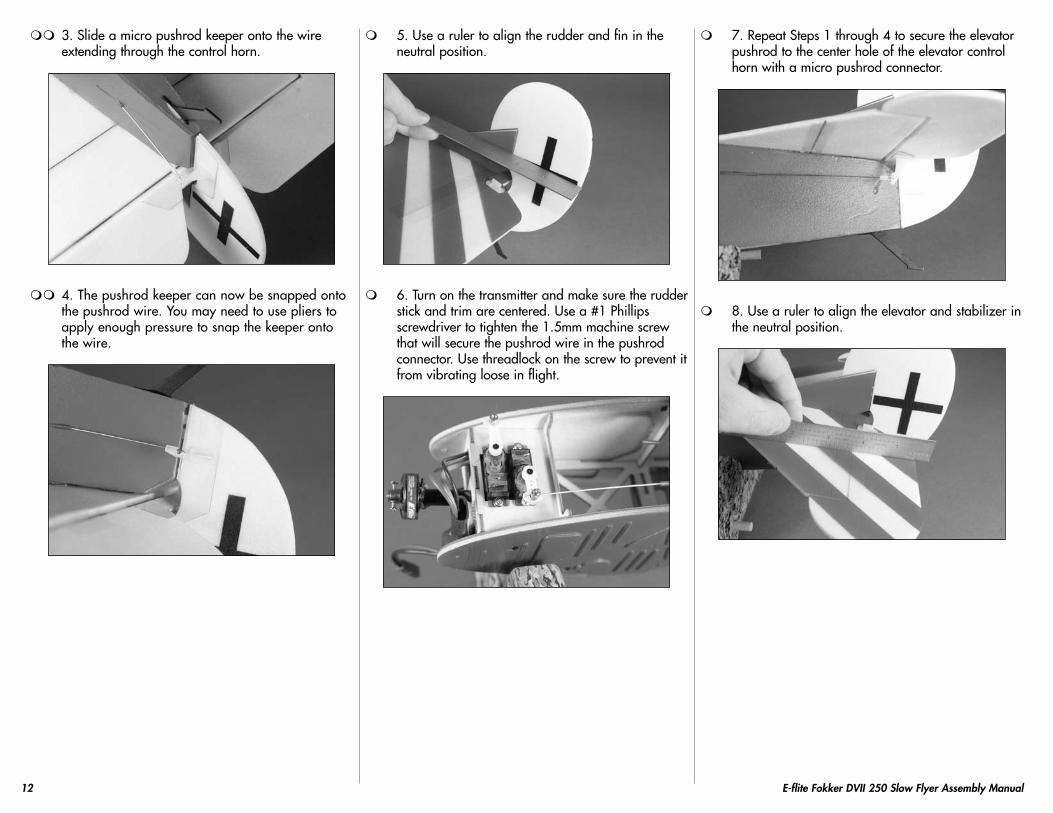
3. Slide a micro pushrod keeper onto the wire extending through the control horn.
4. The pushrod keeper can now be snapped onto the pushrod wire. You may need to use pliers to apply enough pressure to snap the keeper onto the wire.
5. Use a ruler to align the rudder and fin in the neutral position.
6. Turn on the transmitter and make sure the rudder stick and trim are centered. Use a #1 Phillips screwdriver to tighten the 1.5mm machine screw that will secure the pushrod wire in the pushrod connector. Use threadlock on the screw to prevent it from vibrating loose in flight.
7. Repeat Steps 1 through 4 to secure the elevator pushrod to the center hole of the elevator control horn with a micro pushrod connector.
8. Use a ruler to align the elevator and stabilizer in the neutral position.

13E-flite Fokker DVII 250 Slow Flyer Assembly Manual
9. Use a #1 Phillips screwdriver to tighten the 1.5mm machine screw that will secure the pushrod wire in the pushrod connector. Use threadlock on the screw to prevent it from vibrating loose in flight.
10. Use side cutters to trim the excess pushrod wire that extends forward of the pushrod connector on both the rudder and elevator servos.
Cowling InstallationRequired Parts
Fuselage assembly TransmitterPropeller Motor batteryCowling2mm x 8mm wood screw (black) (3)
Required Tools and AdhesivesPhillips screwdriver: #1
Important Information About Your Brushless ESCMake sure your ESC brake is programmed to Off. Also, be sure to use an ESC with the
proper low-voltage cutoff and be sure it is set correctly for the batteries you are using.
Never check the motor rotation on the bench with the propeller installed. The plane could
move and cause serious injury. Always check the motor without the propeller to avoid injury.
1. Slide the cowling on the fuselage. Use the three screws removed from the cowling and a #1 Phillips screwdriver to attach the cowling.
2. Turn on the transmitter and bring the throttle trim and stick to the low throttle position. Plug the battery into the speed control and check the operation of the motor. It should rotate counterclockwise when viewed from the front of the aircraft. Use the instructions provided with your ESC to make corrections to the direction of rotation of the motor if necessary.
Important Information About Your PropellerIt is very important to check to be sure
the propeller is balanced before installing onto the shaft. An unbalanced propeller
may cause poor flight characteristics.
3. Attach the propeller to the motor using the materials and instructions provided with your particular motor.
4. Unplug the battery from the speed control and turn off the transmitter before proceeding.

14 E-flite Fokker DVII 250 Slow Flyer Assembly Manual
Scale Accessory InstallationRequired Parts
Airframe Machine gun (right and left)Required Tools and Adhesives
Foam-safe CA
1. Use foam-safe CA to attach the machine gun to the top of the fuselage.
There is a right and left machine gun. Make sure the clip from each machine gun faces away from the fuselage center line as shown in the photos.
Bottom WingRequired Parts
Fuselage assembly Bottom wing2mm x 8mm wood screw (4)
Required Tools and AdhesivesPhillips screwdriver: #1
1. Use a #1 Phillips screwdriver and four 2mm x 8mm wood screws to secure the bottom wing to the fuselage. Ensure you do not overtighten the screws and crush the wing.
Cabane Strut InstallationRequired Parts
Fuselage assembly Cabane strut (right and left)Top wing
Required Tools and Adhesives30-minute epoxy
1. Locate the cabane struts. Note that they are pre-bent to fit to the fuselage.
2. You will want to test fit the strut to the fuselage as they can be tricky to install. Insert each end of the strut in the order shown when fitting the cabane strut.
15E-flite Fokker DVII 250 Slow Flyer Assembly Manual
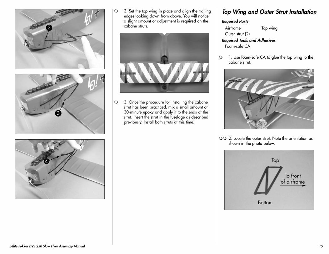
3. Set the top wing in place and align the trailing edges looking down from above. You will notice a slight amount of adjustment is required on the cabane struts.
3. Once the procedure for installing the cabane strut has been practiced, mix a small amount of 30-minute epoxy and apply it to the ends of the strut. Insert the strut in the fuselage as described previously. Install both struts at this time.
Top Wing and Outer Strut InstallationRequired Parts
Airframe Top wingOuter strut (2)
Required Tools and AdhesivesFoam-safe CA
1. Use foam-safe CA to glue the top wing to the cabane strut.
2. Locate the outer strut. Note the orientation as shown in the photo below.

16 E-flite Fokker DVII 250 Slow Flyer Assembly Manual
3. Use foam-safe CA to glue the outer strut to the top and bottom wing after checking the fit of the strut. Allow the CA to fully cure before proceeding.
4. Repeat Steps 2 and 3 to install the remaining outer strut.
Landing Gear InstallationRequired Parts
Fuselage assemblyLanding gear Wheel (2)Wheel retainer (2) Double-sided tape
Required Tools and AdhesivesHobby knife with #11 blade Foam-safe CALow-temp hot glue
1. Slide one of the wheels onto the landing gear. The wheel should rotate freely on the gear. If not, use a hobby knife and #11 blade to enlarge the hole in the wheel slightly for free rotation.
2. Slide the wheel retainer onto the landing gear wire. Use a drop of foam-safe CA on the side away from the wheel to secure the retainer. Make sure not to get CA on the wheel or axle, preventing the wheel from rotating.
3. Install the remaining wheel and secure it following the procedure described in Steps 1 and 2.

17E-flite Fokker DVII 250 Slow Flyer Assembly Manual
4. Make sure the receiver is out of the way of the landing gear area as well as the connector for the battery on the speed control.
5. Slide the landing gear in the fuselage. The rear of the gear fits into the slot in the middle of the bottom wing, while the front of the gear fits between the formers of the fuselage right behind the cowling. Press the gear in until fully seated, making sure not to damage the fuselage in the process.
6. You may find the gear is slightly loose when installed. Use foam-safe CA to glue the landing gear wire in position so it does not separate from the airframe in flight.
7. Use double-sided tape to secure the receiver in the fuselage as shown. Make sure both antenna wires are straight out of the receiver for the best reception of the radio system.
8. Use low-temp hot glue to attach the landing gear wing to the landing gear. Use three small dots of glue to glue the wing in place.
18 E-flite Fokker DVII 250 Slow Flyer Assembly Manual
Rigging InstallationRequired Parts
Airframe Rigging threadMotor battery Hook and loop tape
Required Tools and AdhesivesFoam-safe CA Thin CANeedle White glueLow-tack tape Hobby scissorsHobby knife with #11 blade
Installing the rigging will add to the appearance and strength of your airplane, but you will not be
able to remove the wings without cutting the rigging. The rigging is required on your model. DO NOT
fly your model before installing the rigging.
You may want to thread the rigging through a needle to make it easier to pass the rigging
through the holes, especially the tubes in the fuselage near the bottom wing.
Another option is to soak the last 4 inches (100mm) of the rigging line with thin CA to stiffen
it up so you can pass it through all the holes.
1. Cut the rigging thread in half. You will need two pieces of thread to accomplish the rigging on the Fokker DVII.
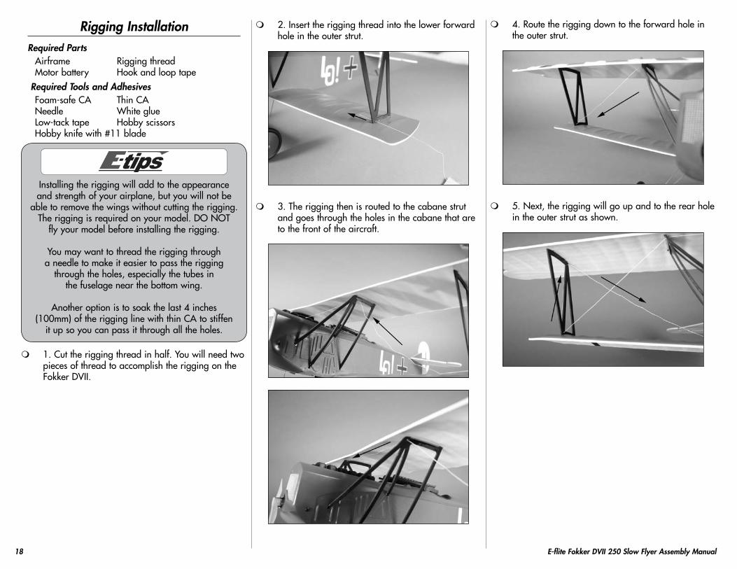
2. Insert the rigging thread into the lower forward hole in the outer strut.
3. The rigging then is routed to the cabane strut and goes through the holes in the cabane that are to the front of the aircraft.
4. Route the rigging down to the forward hole in the outer strut.
5. Next, the rigging will go up and to the rear hole in the outer strut as shown.

19E-flite Fokker DVII 250 Slow Flyer Assembly Manual
6. The rigging will now go through the rear tube in the fuselage. Note that the rigging in this step must be behind the rigging headed upward (Step 3).
7. After exiting the tube, route the rigging up and to the rear hole in the outer cabane strut as shown.
8. To complete the first stage of rigging, tie the rigging at the top of the strut as shown. Use low-tack tape to secure the tape on the underside of the bottom wing. The end taped will be secured once the rigging is ready to be tensioned.
9. The second stage of rigging is similar to the first. Start by inserting the rigging thread through the rear hole in the outer strut.
10. The rigging now heads to the cabane strut to go through the rear holes in the struts. This line will be in front of the current rigging lines.

20 E-flite Fokker DVII 250 Slow Flyer Assembly Manual
11. The rigging now heads to the rear hole in the outer strut. Again, this line will be in front of the current rigging lines.
12. Route the rigging up and to the forward hole in the outer strut.
13. The rigging now goes down and through the forward tube in the fuselage. This line will be in front of all the other rigging lines.
14. After exiting the fuselage, route the rigging up to the forward hole in the outer strut. Make sure the rigging is in front of all the previously installed rigging lines.
15. This completes the second stage of rigging. Use low-tack tape to secure the tape on the underside of the bottom wing. The end taped will be secured once the rigging is ready to be tensioned.

21E-flite Fokker DVII 250 Slow Flyer Assembly Manual
16. Use the following images to verify the rigging installation. When tensioned, the lines will all run perfectly straight and not cause others to be moved out of position.
17. Apply light tension on the rigging lines. Use a drop of foam-safe CA at each point the rigging passes through the struts. Allow the CA to fully cure before moving your model. Don’t forget to tie the ends that were taped to the bottom of the wing at this time as well.
18. Use a small amount of white glue to glue the rigging at the fuselage. This will make it easier to remove the rigging lines if you need to remove the wings from your model.
19. Use scissors to trim any excess rigging from the model at this time.
20. Use hook and loop tape to mount the battery in the fuselage as shown.

22 E-flite Fokker DVII 250 Slow Flyer Assembly Manual
Center of Gravity
An important part of preparing the aircraft for flight is properly balancing the model.
Caution: Do not inadvertently skip this step!
The recommended Center of Gravity (CG) location for the Fokker DVII 250 Slow Flyer is 13/4 to 2 inches (44 to 51mm) back from the leading edge of the top wing as shown with the battery pack installed.
When balancing your model, support the plane upright at the marks made on the wing with your fingers or a commercially available balancing stand. This is the correct balance point for your model.
Adjust the motor battery as necessary so the model is level or slightly nose down. This is the correct balance point for your model. You should find the CG to be very close with the battery installed forward in the battery area inside the cowling.
After the first flights, the CG position can be adjusted for your personal preference.
Control Throws
1. Turn on the transmitter and receiver of your Fokker DVII 250 Slow Flyer. Check the movement of the rudder using the transmitter. When the stick is moved right, the rudder should also move right. Reverse the direction of the servo at the transmitter if necessary.
2. Check the movement of the elevator with the radio system. Moving the elevator stick forward will make the airplane elevator move up.
3. Use a ruler to adjust the throw of the elevator and rudder. Adjust the position of the pushrod at the control horn to achieve the following measurements when moving the sticks to their endpoints.
Elevator Low RateUp 3/8-inch (9mm)Down 3/8-inch (9mm)Elevator High RateUp 1/2-inch (12.5mm)Down 1/2-inch (12.5mm)Rudder Low RateUp 1-inch (25.5mm)Down 1-inch (25.5mm)Rudder High RateUp 11/4-inch (31.5mm)Down 11/4-inch (31.5mm)
Measurements are taken at the inner or widest point on the control surface.
These are general guidelines measured from our own flight tests. You can experiment with higher rates to match your preferred style of flying.
Travel Adjust, Sub-Trim and Dual Rates are not listed and should be adjusted according to each individual model and preference.
23E-flite Fokker DVII 250 Slow Flyer Assembly Manual
PreflightCheck Your Radio
Before going to the field, be sure that your batteries are fully charged per the instructions included with your radio. Charge both the transmitter and receiver pack for your airplane. Use the recommended charger supplied with your particular radio system, following the instructions provided with the radio. In most cases, the radio should be charged the night before going out flying.
Before each flying session, be sure to range check your radio. See your radio manual for the recommended range and instructions for your radio system. Each radio manufacturer specifies different procedures for their radio systems. Next, start the motor. With the model securely anchored, check the range again. The range test should not be significantly affected. If it is, don’t attempt to fly! Have your radio equipment checked out by the manufacturer.
Keep loose items that can get entangled in the propeller away from the prop. These
include loose clothing, or other objects such as pencils and screwdrivers. Especially keep
your hands away from the propeller.
Double-check that all controls (aileron, elevator, rudder and throttle) move in the correct direction.
Check the radio installation and make sure all the control surfaces are moving correctly (i.e., the correct direction and with the recommended throws). Test run the motor and make sure it transitions smoothly from off to full throttle and back. Also ensure the engine is installed according to the manufacturer’s instructions, and it will operate consistently.
Check all the control horns, servo horns, and clevises to make sure they are secure and in good condition. Replace any items that would be considered questionable. Failure of any of these components in flight would mean the loss of your aircraft.
Flying Your Fokker DVII Slow Flyer
You will find the Fokker DVII Slow Flyer to be a solid, honest-flying model.
Ensure your CG is set according to the manual and power up the aircraft. Move your throttle trim up slowly until the motor just begins to spin. This will be your flight idle that will help to establish a longer glide path and to make landings easier. Before taxiing out to the runway, double-check all controls are working in the correct direction and functioning properly. You will find the rudder very effective; on the ground, tracking is very predictable. Apply power smoothly and begin the takeoff roll. Correct with rudder as necessary and apply up elevator slowly until the model lifts off.
You will find flying the Fokker DVII Slow Flyer to be very relaxing and easy. The model is not designed for high-speed flight. Most flight is accomplished below half throttle and will yield flights in excess of 20 minutes with an 800mAh 2-cell battery with a Park 250 when outfitted with the GWS 7 x 3.5 prop. Landing the Fokker DVII Slow Flyer is as easy as setting up on final approach, lowering the throttle to idle and gliding in to a soft touch-down.
You will find the Fokker DVII 250 Slow Flyer capable of basic loops and stall turns. Flying these
maneuvers is easy and fun with the Fokker DVII 250 Slow Flyer. After your first flight you will want
to check your rigging to make sure none of the locations that were glued with CA have loosened.
Check these areas on a regular basis to ensure safe and reliable operation. We hope you enjoy the experience of flying the Fokker DVII Slow Flyer.
Happy landings.
Range Test Your Radio
Before each flying session, and especially with a new model, it is important to perform a range check. It is helpful to have another person available to assist during the range check. If you are using a Spektrum transmitter, please refer to your transmitter’s manual for detailed instructions on the range check process.
1. With the model resting on the ground, stand 30 paces (approximately 90 feet) away from the model.
2. Face the model with the transmitter in your normal flying position. Be sure the throttle is in the full down position and plug the flight battery into the speed control.
3. As you move the controls, watch to be sure the airplane’s motor and controls operate smoothly. You should have total control of the model at 30 paces (90 feet).
4. If control issues exist, call the Horizon Support Team at 1 877 504 0233 or go to horizonhobby.com to find a local Spektrum distributor in your country for service if you are using a Spektrum radio system.

24 E-flite Fokker DVII 250 Slow Flyer Assembly Manual
Safety Do’s and Don’ts for Pilots
• Checkallcontrolsurfacespriortoeachtakeoff.
• Donotflyyourmodelnearspectators,parkingareas or any other area that could result in injury to people or damage of property.
• Donotflyduringadverseweatherconditions.Poorvisibility can cause disorientation and loss of control of your aircraft. Strong winds can cause similar problems.
• Donottakechances.Ifatanytimeduringflightyouobserve any erratic or abnormal operation, land immediately and do not resume flight until the cause of the problem has been ascertained and corrected. Safety can never be taken lightly.
• Donotflynearpowerlines.
Daily Flight Checks
1. Check the battery voltage of the transmitter battery. Do not fly below the manufacturer’s recommended voltage. To do so can crash your aircraft.
When you check these batteries, ensure that you have the polarities correct on your expanded scale voltmeter.
2. Check all hardware (linkages, screws, nuts, and bolts) prior to each day’s flight. Be sure that binding does not occur and that all parts are properly secured.
3. Ensure that all surfaces are moving in the proper manner.
4. Perform a ground range check before each day’s flying session.
5. Prior to starting your aircraft, turn off your transmitter, then turn it back on. Do this each time you start your aircraft. If any critical switches are on without your knowledge, the transmitter alarm will sound a warning at this time.
6. Check that all trim levers are in the proper location.
7. All servo pigtails and switch harness plugs should be secured in the receiver. Make sure that the switch harness moves freely in both directions.
Warranty Information
WARRANTY PERIOD
Exclusive Warranty- Horizon Hobby, Inc., (Horizon) warranties that the Products purchased (the “Product”) will be free from defects in materials and workmanship at the date of purchase by the Purchaser.
LIMITED WARRANTY
(a) This warranty is limited to the original Purchaser (“Purchaser”) and is not transferable. REPAIR OR REPLACEMENT AS PROVIDED UNDER THIS WARRANTY IS THE EXCLUSIVE REMEDY OF THE PURCHASER. This warranty covers only those Products purchased from an authorized Horizon dealer. Third party transactions are not covered by this warranty. Proof of purchase is required for warranty claims. Further, Horizon reserves the right to change or modify this warranty without notice and disclaims all other warranties, express or implied.
(b) Limitations- HORIZON MAKES NO WARRANTY OR REPRESENTATION, EXPRESS OR IMPLIED, ABOUT NON-INFRINGEMENT, MERCHANTABILITY OR FITNESS FOR A PARTICULAR PURPOSE OF THE PRODUCT. THE PURCHASER ACKNOWLEDGES THAT THEY ALONE HAVE DETERMINED THAT THE PRODUCT WILL SUITABLY MEET THE REQUIREMENTS OF THE PURCHASER’S INTENDED USE.
(c) Purchaser Remedy- Horizon’s sole obligation hereunder shall be that Horizon will, at its option, (i) repair or (ii) replace, any Product determined by Horizon to be defective. In the event of a defect, these are the Purchaser’s exclusive remedies. Horizon reserves the right to inspect any and all equipment involved in a warranty claim. Repair or replacement decisions are at the sole discretion of Horizon. This warranty does not cover cosmetic damage or damage due to acts of God, accident, misuse, abuse, negligence, commercial use, or modification of or to any part of the Product. This warranty does not cover damage due to improper installation, operation, maintenance, or attempted repair by anyone other than Horizon. Return of any goods by Purchaser must be approved in writing by Horizon before shipment.

25E-flite Fokker DVII 250 Slow Flyer Assembly Manual
DAMAGE LIMITS
HORIZON SHALL NOT BE LIABLE FOR SPECIAL, INDIRECT OR CONSEQUENTIAL DAMAGES, LOSS OF PROFITS OR PRODUCTION OR COMMERCIAL LOSS IN ANY WAY CONNECTED WITH THE PRODUCT, WHETHER SUCH CLAIM IS BASED IN CONTRACT, WARRANTY, NEGLIGENCE, OR STRICT LIABILITY. Further, in no event shall the liability of Horizon exceed the individual price of the Product on which liability is asserted. As Horizon has no control over use, setup, final assembly, modification or misuse, no liability shall be assumed nor accepted for any resulting damage or injury. By the act of use, setup or assembly, the user accepts all resulting liability.
If you as the Purchaser or user are not prepared to accept the liability associated with the use of this Product, you are advised to return this Product immediately in new and unused condition to the place of purchase.
Law: These Terms are governed by Illinois law (without regard to conflict of law principals).
SAFETY PRECAUTIONS
This is a sophisticated hobby Product and not a toy. It must be operated with caution and common sense and requires some basic mechanical ability. Failure to operate this Product in a safe and responsible manner could result in injury or damage to the Product or other property. This Product is not intended for use by children without direct adult supervision. The Product manual contains instructions for safety, operation and maintenance. It is essential to read and follow all the instructions and warnings in the manual, prior to assembly, setup or use, in order to operate correctly and avoid damage or injury.
QUESTIONS, ASSISTANCE, AND REPAIRS
Your local hobby store and/or place of purchase cannot provide warranty support or repair. Once assembly, setup or use of the Product has been started, you must contact Horizon directly. This will enable Horizon to better answer your questions and service you in the event that you may need any assistance. For questions or assistance, please direct your email to [email protected], or call 877.504.0233 toll free to speak to a service technician.
INSPECTION OR REPAIRS
If this Product needs to be inspected or repaired, please call for a Return Merchandise Authorization (RMA). Pack the Product securely using a shipping carton. Please note that original boxes may be included, but are not designed to withstand the rigors of shipping without additional protection. Ship via a carrier that provides tracking and insurance for lost or damaged parcels, as Horizon is not responsible for merchandise until it arrives and is accepted at our facility. A Service Repair Request is available at www.horizonhobby.com on the “Support” tab. If you do not have internet access, please include a letter with your complete name, street address, email address and phone number where you can be reached during business days, your RMA number, a list of the included items, method of payment for any non-warranty expenses and a brief summary of the problem. Your original sales receipt must also be included for warranty consideration. Be sure your name, address, and RMA number are clearly written on the outside of the shipping carton.
WARRANTY INSPECTION AND REPAIRS
To receive warranty service, you must include your original sales receipt verifying the proof-of-purchase date. Provided warranty conditions have been met, your Product will be repaired or replaced free of charge. Repair or replacement decisions are at the sole discretion of Horizon Hobby.
NON-WARRANTY REPAIRS
Should your repair not be covered by warranty the repair will be completed and payment will be required without notification or estimate of the expense unless the expense exceeds 50% of the retail purchase cost. By submitting the item for repair you are agreeing to payment of the repair without notification. Repair estimates are available upon request. You must include this request with your repair. Non-warranty repair estimates will be billed a minimum of 1/2 hour of labor. In addition you will be billed for return freight. Please advise us of your preferred method of payment. Horizon accepts money orders and cashiers checks, as well as Visa, MasterCard, American Express, and Discover cards. If you choose to pay by credit card, please include your credit card number and expiration date. Any repair left unpaid or unclaimed after 90 days will be considered abandoned and will be disposed of accordingly. Please note: non-warranty repair is only available on electronics and model engines.United States:Electronics and engines requiring inspection or repair should be shipped to the following address:
Horizon Service Center4105 Fieldstone Road
Champaign, Illinois 61822USA
All other Products requiring warranty inspection or repair should be shipped to the following address:
Horizon Product Support4105 Fieldstone Road
Champaign, Illinois 61822USA
Please call 877-504-0233 or e-mail us at [email protected] with any questions or concerns regarding this product or warranty.

26 E-flite Fokker DVII 250 Slow Flyer Assembly Manual
United Kingdom:Electronics and engines requiring inspection or repair should be shipped to the following address:
Horizon Hobby UKUnits 1-4 Ployters Rd
Staple TyeHarlow, EssexCM18 7NS
United Kingdom
Please call +44 (0) 1279 641 097 or e-mail us at [email protected] with any questions or concerns regarding this product or warranty.Germany:Electronics and engines requiring inspection or repair should be shipped to the following address:
Horizon Technischer ServiceHamburger Strasse 10
25335 ElmshornGermany
Please call +49 4121 46199 66 or e-mail us at [email protected] with any questions or concerns regarding this product or warranty.
Compliance Information for the European Union
INSTRUCTIONS FOR DISPOSAL OF WEEE BY USERS IN THE EUROPEAN UNION
This product must not be disposed of with other waste. Instead, it is the user’s responsibility to dispose of their waste equipment by handing it over to a designated collection point for the recycling of waste electrical and electronic equipment. The separate collection and recycling of your waste equipment at the time of disposal will help to conserve natural resources and ensure that it is recycled in a manner that protects human health and the environment. For more information about where you can drop off your waste equipment for recycling, please contact your local city office, your household waste disposal service or where you purchased the product.
Age Recommendation: 14 years or over. Not a toy. Not intended for use by children without direct adult supervision.
2009 Official Academy of Model Aeronautics Safety Code
GENERAL
1. A model aircraft shall be defined as a non-human-carrying device capable of sustained flight in the atmosphere. It shall not exceed limitations established in this code and is intended to be used exclusively for recreational or competition activity.
2. The maximum takeoff weight of a model aircraft, including fuel, is 55 pounds, except for those flown under the AMA Experimental Aircraft Rules.
3. I will abide by this Safety Code and all rules established for the flying site I use. I will not willfully fly my model aircraft in a reckless and/or dangerous manner.
4. I will not fly my model aircraft in sanctioned events, air shows, or model demonstrations until it has been proven airworthy.
5. I will not fly my model aircraft higher than approximately 400 feet above ground level, when within three (3) miles of an airport without notifying the airport operator. I will yield the right-of-way and avoid flying in the proximity of full-scale aircraft, utilizing a spotter when appropriate.
6. I will not fly my model aircraft unless it is identified with my name and address, or AMA number, inside or affixed to the outside of the model aircraft. This does not apply to model aircraft flown indoors.
7. I will not operate model aircraft with metal-blade propellers or with gaseous boosts (other than air), nor will I operate model aircraft with fuels containing tetranitromethane or hydrazine.

27E-flite Fokker DVII 250 Slow Flyer Assembly Manual
8. I will not operate model aircraft carrying pyrotechnic devices which explode burn, or propel a projectile of any kind. Exceptions include Free Flight fuses or devices that burn producing smoke and are securely attached to the model aircraft during flight. Rocket motors up to a G-series size may be used, provided they remain firmly attached to the model aircraft during flight. Model rockets may be flown in accordance with the National Model Rocketry Safety Code; however, they may not be launched from model aircraft. Officially designated AMA Air Show Teams (AST) are authorized to use devices and practices as defined within the Air Show Advisory Committee Document.
9. I will not operate my model aircraft while under the influence of alcohol or within eight (8) hours of having consumed alcohol.
10. I will not operate my model aircraft while using any drug which could adversely affect my ability to safely control my model aircraft.
11. Children under six (6) years old are only allowed on a flightline or in a flight area as a pilot or while under flight instruction.
12. When and where required by rule, helmets must be properly worn and fastened. They must be OSHA, DOT, ANSI, SNELL or NOCSAE approved or comply with comparable standards.
RADIO CONTROL
1. All model flying shall be conducted in a manner to avoid over flight of unprotected people.
2. I will have completed a successful radio equipment ground-range check before the first flight of a new or repaired model aircraft.
3. I will not fly my model aircraft in the presence of spectators until I become a proficient flier, unless I am assisted by an experienced pilot.
4. At all flying sites a line must be established, in front of which all flying takes place. Only personnel associated with flying the model aircraft are allowed at or in front of the line. In the case of airshows demonstrations straight line must be established. An area away from the line must be maintained for spectators. Intentional flying behind the line is prohibited.
5. I will operate my model aircraft using only radio-control frequencies currently allowed by the Federal Communications Commission (FCC). Only individuals properly licensed by the FCC are authorized to operate equipment on Amateur Band frequencies.
6. I will not knowingly operate my model aircraft within three (3) miles of any preexisting flying site without a frequency-management agreement. A frequency management agreement may be an allocation of frequencies for each site, a day-use agreement between sites, or testing which determines that no interference exists. A frequency-management agreement may exist between two or more AMA chartered clubs, AMA clubs and individual AMA members, or individual AMA members. Frequency-management agreements, including an interference test report if the agreement indicates no interference exists, will be signed by all parties and copies provided to AMA Headquarters.
7. With the exception of events flown under official AMA rules, no powered model may be flown outdoors closer than 25 feet to any individual, except for the pilot and located at the flightline.
8. Under no circumstances may a pilot or other person touch a model aircraft in flight while it is still under power, except to divert it from striking an individual.
9. Radio-controlled night flying is limited to low-performance model aircraft (less than 100 mph). The model aircraft must be equipped with a lighting system which clearly defines the aircraft’s attitude and direction at all times.
10. The operator of a radio-controlled model aircraft shall control it during the entire flight, maintaining visual contact without enhancement other than by corrective lenses that are prescribed for the pilot. No model aircraft shall be equipped with devices which allow it to be flown to a selected location which is beyond the visual range of the pilot.
Fokker DVII Safe Operating Recommendations
- Inspect your model before every flight to make certain it is airworthy.
- Be aware of any other radio frequency user who may present an interference problem.
- Always be courteous and respectful of other users of your selected flight area.
- Choose an area clear of obstacles and large enough to safely accommodate your flying activity.
- Make certain this area is clear of friends and spectators prior to launching your aircraft.
- Be aware of other activities in the vicinity of your flight path that could cause potential conflict.
- Carefully plan your flight path prior to launch.
- Abide by any and all established AMA National Model Aircraft Safety Code.

16771 Printed 10/2009
Horizon Hobby USA4105 Fieldstone Road
Champaign, Illinois 61822USA
(877) 504-0233
Horizon Hobby UKUnits 1-4 Ployters Rd
Staple TyeHarlow, EssexCM18 7NS
United Kingdom+44 (0) 1279 641 097
Horizon Hobby Deutschland GmbHHamburger Strasse 10
25335 ElmshornGermany
+49 4121 46199 60
© 2010 Horizon Hobby, Inc.horizonhobby.com www.e-fliterc.com