focused feasibility study, bullion mine ou6 jefferson ... · the remediation alternatives were...
TRANSCRIPT
F i na l Vo lume 2
Focused Feasibility Study, Bullion Mine OU6
Jefferson County, Montana
Prepared for U.S. Environmental Protection Agency
Region 8, Helena, Montana
November 2013
Prepared by


Executive Summary This report presents the draft feasibility study (FS) for the Bullion Mine Site (the Site). The FS was prepared by CH2M HILL on behalf of the U.S. Environmental Protection Agency. The FS addresses human health and environment risks identified in the November 2013 Final Focused Remedial Investigation by CH2M HILL.
The U.S. Environmental Protection Agency (EPA) has determined that Interim Records of Decision (RODs) are needed to address the acidic mine drainage from both the Bullion (OU6) and Crystal (OU5) mine sites located within the Basin Watershed Operable Unit (OU2). In accordance with Agency guidance, these interim RODs will be protective of human health and the environment in the short term and are intended to provide adequate protection until a final ROD for the Basin Watershed is signed. Therefore, the actions resulting from this focused FS process are not intended to address fully the statutory mandate for permanence and treatment to the maximum extent practicable, yet it will support those statutory mandates.
Potential Applicable or Relevant and Appropriate Requirements (ARARs) will be addressed in detail as part of the Basin Watershed OU2 ROD. The Bullion Mine OU6 cleanup will be an interim remedial action where compliance with groundwater and surface water ARARs is concerned. EPA doesn’t expect that this action will result in final compliance with surface and ground water ARARs at the Basin Mining District National Priorities List (NPL) Site. For now, EPA is invoking the interim action waiver as provided in 40 CFR § 300.430(f)(1)(ii)(C)(1) with respect to all water quality ARARs at OU6. It should be noted that EPA expects all other ARARs for the Bullion Mine OU6 action to be complied with during or at completion of the action, as appropriate.
Remediation alternatives were developed. Potentially applicable technologies were identified and screened to obtain a set of technologies feasible for use in achieving the PRAOs and PRGs. Retained technologies were assembled into remediation alternatives that cover the full range of possible response actions. The alternatives were then screened according to effectiveness, implementability, and cost to eliminate alternatives that were impractical, infeasible, or have high costs relative to other alternatives without being more effective.
A number of remediation elements (common elements) were used in multiple alternatives. To streamline the FS, the common elements were evaluated independently and then applied to each alternative. The common elements retained for all alternatives were as follows:
• Mine water removal from lower adit, treatment, and discharge. Pump and treat mine water, clear soil/debris plug from lower adit to facilitate free flow of mine water.
• Surface water and shallow groundwater control. Three of the alternatives include a collection and transport system for surface and shallow groundwater.
• Adit discharge control. Two options were evaluated for collecting and transporting adit discharge for treatment.
• Improve ground surface reclamation features. Improve surface reclamation where inadequate soil and vegetative cover have resulted in exposed mineralized material.
The following alternatives, coupled with the common elements, were retained for remediation of the Bullion Mine:
• Alternative 1—No Further Action
• Groundwater Treatment
− Alternative 2. Block acid mine drainage (AMD) by tunnel sealing through re-opened tunnel. − Alternative 3. Active treatment, control of AMD flow, and high-density sludge treatment plant or
comparable process. − Alternative 4. Semi-active treatment, control of AMD flow, and lime injection with settling ponds. − Alternative 5. Semi-passive treatment, control of AMD and sulfate reducing bioreactor.
ES110413144041BOI ES-1

EXECUTIVE SUMMARY
The remediation alternatives were evaluated using the following criteria established in the NCP (40 CFR 300.430):
• Overall Protection of Human Health and the Environment • Compliance with ARARs • Long-Term Effectiveness and Permanence • Reduction of Toxicity, Mobility, and Volume through Treatment • Short-term Effectiveness • Implementability • Cost
Table ES-1 presents a summary of the comparison of remedial alternatives by EPA criteria.
This FS, when finalized, will be used to select a preferred alternative for remediating the Site. The preferred alternative will be presented in a Proposed Plan (PP) that will be subject to public comment. The PP will briefly summarize the results of the remedial investigation (RI) and feasibility study (FS), and allow the State of Montana and the general public an opportunity to provide comments to EPA prior to finalizing a remedial approach in a Record of Decision. EPA will hold a public meeting to explain the RI/FS and proposed remedial alternatives. This will also serve as a forum for EPA to hear concerns from community members and interested stakeholders. A Responsiveness Summary will be prepared by EPA for all written and verbal comments provided on the PP, prior to finalizing a ROD. Once the ROD is issued, EPA will move forward with Remedial Design planning and development. Finally, EPA will proceed with implementing a Remedial Action at the Site in accordance with the ROD.
ES-2 ES110413144041BOI

EXECUTIVE SUMMARY
TABLE ES-1 Comparison of Remediation Alternatives
1—No Further
Action 2—Mine Plugging by
Re-opening Adit 3—Active Treatment of AMD 4—Semi-Active Treatment of
AMD 5—Semi-Passive Treatment of
AMD
Overall Protection of Human Health and the Environment
Not protective of human health and the environment.
Potentially protective of human health and the environment for AMD. High degree of uncertainty for long term protection because of potential plug failure and potential for AMD to seep out through fractures to multiple surface expressions.
Protective of human health and the environment for AMD. Long term protectiveness is more certain than with mine plugging alternatives because of less uncertainty and use of proven technology.
Less protective than active treatment because AMD is not as thoroughly and consistently treated. Treatment process application is more variable and less monitored as proposed than Alt 3.
Less protective than semi-active treatment because AMD treatment system is passive (no mechanical mixing) more reliant on naturally induced chemical reactions, subject to more variability in application. Subject to natural upset with less operational management.
Compliance with ARARs Does not meet water quality standards.
Surface and groundwater ARARs are waived for OU6; however, implementation of this remedial alternative will contribute to the overall compliance with ARARs for the Basin Watershed OU2. Degree of compliance depends on effectiveness of plugging to eliminate point discharge and containing the AMD.
Surface and groundwater ARARs are waived for OU6; however, implementation of this remedial alternative will contribute to the overall compliance with ARARs for the Basin Watershed OU2. Degree of compliance would be high because treatment can be tailored to meet most water quality standards.
Surface and groundwater ARARs are waived for OU6; however, implementation of this remedial alternative will contribute to the overall compliance with ARARs for the Basin Watershed OU2. Degree of compliance would depend on consistent process implementation and attention to operational and maintenance needs.
Surface and groundwater ARARs are waived for OU6; however, implementation of this remedial alternative will contribute to the overall compliance with ARARs for the Basin Watershed OU2. Degree of compliance would depend on initiation of natural geochemical processes, reduction of upsets, and effective monitoring and maintenance.
Long-Term Effectiveness Does not address PRGs. Not effective in long term.
Highly uncertain long-term effectiveness and permanence; dependent on proper construction and on unknown fracture conditions of bedrock. Potential for plug failure or for development of new paths of AMD leakage through fractures to surface expressions.
Expected to consistently meet water quality standards for adit discharge water. More reliable than mine plugging. Dependent on proper construction and continuous long-term operation and maintenance.
Expected to frequently meet water quality standards for adit discharge water. More reliable than mine plugging. Highly dependent on proper construction and continuous long-term operation and maintenance.
Expected to frequently meet water quality standards for adit discharge water. More reliable than mine plugging. Highly dependent on proper construction and less involved long-term maintenance.
Short-Term Effectiveness Does not create short-term construction risks.
Short-term construction risks are high because of confined space entry underground, which requires strict adherence to Mine Safety and Health Administration regulations, typical of tunneling and mining projects.
Short-term construction risk typical of light industrial building and transport of equipment and materials to the Site.
Construction risk lower than Alternative 3 because system is less complex, but potentially for 2 years.
Construction risk lower than Alternative 3 because system is less complex, but potentially for 2 years.
ES110413144041BOI ES-3

EXECUTIVE SUMMARY
TABLE ES-1 Comparison of Remediation Alternatives
1—No Further
Action 2—Mine Plugging by
Re-opening Adit 3—Active Treatment of AMD 4—Semi-Active Treatment of
AMD 5—Semi-Passive Treatment of
AMD
Reduction in Toxicity, Mobility, Volume through Treatment
No treatment provided.
Toxicity, mobility, and volume of AMD could be greatly reduced if mine is completely flooded (reduced oxygen) and plug is 100% effective.
Treats AMD. Most efficient alternative, expected to provide 99 percent reduction in volume, efficiently removes toxicity through treatment. Prevents contaminant mobility.
Treats AMD, prevents contaminant mobility. Expected to provide 85 to 95 percent reduction in volume. Less efficient than Alternative 3 at removing toxicity through treatment.
Treats AMD, greatest range of treatment variability, expected to provide 75 to 95 percent reduction in toxicity and volume. Reduces contaminant mobility through treatment.
Implementability Does not require implementation.
Readily implemented but requires specialized underground mine closure techniques.
Implementability similar to waste water plant construction, but readily accomplished with experience construction personnel. Would require development of power source and other utilities and onsite buildings for operators. May need permission from U.S. Forest Service (USFS) for placement of treatment system elements on USFS property. Permanent road to the Site would need to be constructed and daily traffic on community roads to the Site would increase risk to community.
Similar to Alternative 3 with specialized construction personnel. Almost daily traffic on community roads to the Site would increase risk to community. May need permission from the USFS for placement of treatment system elements on USFS property
Similar to Alternative 3 with specialized construction personnel. May need permission from USFS for placement of treatment system elements on USFS property. Fewer trips to the Site for operation and maintenance and lower traffic risk to community.
Cost (net present value, 30 years, 5% discount rate)
$231,000 $5,443,000 $7,072,000 $4,289,000 $3,778,000
Note: Alternatives 2 through 5 include mobile water treatment costs for mine dewatering.
ES-4 ES110413144041BOI
Contents Section Page
Acronyms and Abbreviations ............................................................................................................................... v
1. Introduction ......................................................................................................................................... 1-1 1.1 Purpose and Organization Report ................................................................................................... 1-1 1.2 Background Information .................................................................................................................. 1-2
1.2.1 Site Description ................................................................................................................... 1-2 1.2.2 Surface Features ................................................................................................................. 1-4 1.2.3 Meteorology ....................................................................................................................... 1-5 1.2.4 Surface Water Hydrology ................................................................................................... 1-5 1.2.5 Geology ............................................................................................................................... 1-6 1.2.6 Hydrogeology ...................................................................................................................... 1-9
1.3 Site History ....................................................................................................................................... 1-9 1.4 Previous Investigations .................................................................................................................... 1-9
1.4.1 Removal Actions ............................................................................................................... 1-10 1.4.2 Remedial Investigation ..................................................................................................... 1-10
1.5 Conceptual Site Model .................................................................................................................. 1-10 1.6 Summary of COPC Nature and Extent ........................................................................................... 1-16
1.6.1 Surface Water ................................................................................................................... 1-16 1.6.2 Groundwater .................................................................................................................... 1-21 1.6.3 Waste Rock and Soils ........................................................................................................ 1-22 1.6.4 Bioavailability of Arsenic and Lead in Soil ........................................................................ 1-27 1.6.5 Stream Sediments ............................................................................................................. 1-27 1.6.6 Macroinvertebrate Survey ................................................................................................ 1-27 1.6.8 Threatened and Endangered Species ............................................................................... 1-31
1.7 Summary of Human Health and Ecological Risk Evaluation .......................................................... 1-31 1.7.1 Introduction ...................................................................................................................... 1-31 1.7.2 Human Health ................................................................................................................... 1-32 1.7.3 Ecological .......................................................................................................................... 1-33 1.7.4 Contaminants of Concern ................................................................................................. 1-34
1.8 Conclusions of the RI ..................................................................................................................... 1-34
2. Remedial Action Goals and Screening of Technologies ......................................................................... 2-1 2.1 Introduction ..................................................................................................................................... 2-1
2.1.1 Remedial Action Objectives ................................................................................................ 2-1 2.1.2 Applicable or Relevant and Appropriate Requirements ..................................................... 2-1 2.1.3 Preliminary Remedial Action Objectives ............................................................................ 2-2 2.1.4 Preliminary Remediation Goals .......................................................................................... 2-3
2.2 Identification and Screening of General Response Actions, Technology Types and Process Options ........................................................................................................................ 2-7 2.2.1 Introduction ........................................................................................................................ 2-7 2.2.2 General Response Actions .................................................................................................. 2-7
3. Development and Screening of Initial Alternatives ............................................................................... 3-1 3.1 Screening of Initial Alternatives ....................................................................................................... 3-1 3.2 Common Elements .......................................................................................................................... 3-1
3.2.1 Adit Discharge—Dewatering, Collection and Conveyance ................................................. 3-2 3.2.2 Contaminated Groundwater Control ................................................................................. 3-3 3.2.3 Waste Rock Removal .......................................................................................................... 3-3
ES110413144041BOI i

CONTENTS
3.3 Description of Retained Remedial Alternatives ............................................................................. 3-13 3.3.1 No Further Action Alternative (Alternative 1) .................................................................. 3-13 3.3.2 Groundwater Media ......................................................................................................... 3-13 3.3.3 Alternative 3—Active Treatment of AMD ........................................................................ 3-18 3.3.4 Alternative 4—Semi-Active Treatment of AMD (Quicklime Injection System) ................ 3-21 3.3.5 Alternative 5—Semi-Passive Treatment of AMD (Sulfate Reducing Bioreactor) ............. 3-22
4. Detailed Analysis of Alternatives .......................................................................................................... 4-1 4.1 Introduction ..................................................................................................................................... 4-1 4.2 Criteria for Evaluation ...................................................................................................................... 4-2 4.3 Individual Analysis of Alternatives ................................................................................................... 4-2
4.3.1 Alternative 1—No Further Action ....................................................................................... 4-2 4.3.2 Alternative 2—Mine Plugging by Re-opening Adit ............................................................. 4-3 4.3.3 Alternative 3—Active Treatment of AMD .......................................................................... 4-4 4.3.4 Alternative 4—Semi-Active Treatment of AMD ................................................................. 4-5 4.3.5 Alternative 5—Semi-Passive Treatment of AMD ............................................................... 4-6
4.4 Comparative Analysis ...................................................................................................................... 4-7 4.4.1 Overall Protection of Human Health and the Environment ............................................... 4-7 4.4.2 Compliance with ARARs ...................................................................................................... 4-8 4.4.3 Long-Term Effectiveness and Permanence ........................................................................ 4-8 4.4.4 Reduction of Toxicity, Mobility, or Volume through Treatment ........................................ 4-9 4.4.5 Short-Term Effectiveness ................................................................................................... 4-9 4.4.6 Implementability .............................................................................................................. 4-10 4.4.7 Availability of Services and Materials ............................................................................... 4-10 4.4.8 Cost ................................................................................................................................... 4-10 4.4.9 State and Community Acceptance ................................................................................... 4-10 4.4.10 Summary of Comparative Analysis ................................................................................... 4-11
5. References ........................................................................................................................................... 5-1
Appendices
A Applicable or Relevant and Appropriate Requirements B Bullion Mine Estimate Adit Discharge C Technical Memorandum(s): Mine Dewatering; Existing Soil/Debris Plug Analysis D Detailed Cost Estimates
Tables Page
1-1 Discharge Summary of the Bullion Mine Lower Adit (1999 – 2011) ............................................................ 1-5 1-2 Exceedance of Human Health MCLs (Totals) and Acute and Chronic Aquatic Life Standards (Dissolved)
by Representative COPCs at Specific Sampling Locations* ........................................................................ 1-21 1-3 Jurisdictional Wetland Acres Observed on the Bullion Mine Survey Area ................................................. 1-28 2-1 Montana Water Quality Standards and National Surface Water Quality Criteria........................................ 2-4 2-2 Sediment Preliminary Remediation Goals for Benthic Infauna .................................................................... 2-5 2-3 Soil Arsenic Preliminary Remediation Goals for Human Health ................................................................... 2-6 2-4 Soil/Sediment Preliminary Remediation Goals for Wildlife.......................................................................... 2-6 2-5 General Response Actions and Technologies for Surface Water, Groundwater, and Soils ......................... 2-9 3-1 Initial Screening of Technologies and Response Actions ............................................................................ 3-14 3-2 Major Components of Alternatives ............................................................................................................ 3-15 3-3 Alternative 4 Design Parameters ................................................................................................................ 3-21 3-4 Alternative 5 Design Parameters ................................................................................................................ 3-23
ii ES110413144041BOI

CONTENTS
4-1 Comparative Analysis*................................................................................................................................ 4-11 4-2 Alternative Cost Comparison – Groundwater (in thousands) .................................................................... 4-11 4-3 Cost of Common Elements (In addition to Remedial Treatment Alternatives) .......................................... 4-12
Figures Page
1-1 Site Location ................................................................................................................................................. 1-3 1-2 Bullion Mine Site Layout ............................................................................................................................... 1-7 1-3 Bullion Mine Conceptual Site Plan .............................................................................................................. 1-11 1-4 Bullion Mine Site Profile ............................................................................................................................. 1-13 1-5 Creek and Spring Sampling Locations in Bullion Mine Site ......................................................................... 1-19 1-6 Soil Pits with Samples Analyzed by XRF ...................................................................................................... 1-23 1-7 Soil Pits with Samples Analyzed by Laboratory Methods ........................................................................... 1-25 1-8 Benthic Macro-Invertebrate Monitoring Locations .................................................................................... 1-29 1-9 Wetlands along Jill Creek and Lower Seep Area ......................................................................................... 1-31 3-1 Adit Discharge Collection Options ................................................................................................................ 3-5 3-2 Discharge Channel Diversion Structure ........................................................................................................ 3-7 3-3 Collection Basin Detail .................................................................................................................................. 3-9 3-4 Groundwater Cut-Off .................................................................................................................................. 3-11 3-5 Collection Basin Detail ................................................................................................................................ 3-19 3-6 High Density Sludge Process Treatment ..................................................................................................... 3-25 3-7 Bullion Semi-Active Treatment ................................................................................................................... 3-27 3-8 Bullion Semi-Active Treatment Section D-D ............................................................................................... 3-29 3-9 Bullion Semi-Active Treatment Section E-E ................................................................................................ 3-31 3-10 Bullion Semi-Passive Treatment ................................................................................................................. 3-33 3-11 Bullion Semi-Passive Treatment Section F-F and Section G-G.................................................................... 3-35 3-12 Bullion Semi-Passive Treatment Section H-H ............................................................................................. 3-37 3-13 Bullion Semi-Passive Treatment Section I-I ................................................................................................ 3-39 Photographs Page
1-1 Jill Creek Flowing through NW Portion of Bullion Mine Site ........................................................................ 1-6 1-2 Bullion Mine Adit Discharge Channel and Reclaimed Area ........................................................................ 1-10 1-3 Erosion Rill Formed through Former Waste Rock Dump Location ............................................................. 1-15 1-4 Aluminum and Iron Oxide Staining Representative of AMD ...................................................................... 1-15 1-5 Lower Adit AMD Entering Jill Creek ............................................................................................................ 1-16 1-6 Spring Discharging in the Slope of the Site near the Lower Adit ................................................................ 1-22 3-1 Bullion Mine lower Portal Current Condition ............................................................................................. 3-16
ES110413144041BOI iii

CONTENTS
This page intentionally left blank.
iv ES110413144041BOI

Acronyms and Abbreviations µg/L micrograms per liter AMD acid mine drainage amsl above mean sea level ARARs applicable or relevant and appropriate requirements ARD acid rock drainage BERA baseline ecological risk assessment bgs below ground surface CDM CDM Federal Programs Corporation CERCLA Comprehensive Environmental Response, Compensation, and Liability Act CFR Code of Federal Regulations COC contaminant of concern COI contaminant of interest COPC contaminant of potential concern EE/CA engineering evaluation/cost analysis ELCR excess lifetime cancer risk EPA U.S. Environmental Protection Agency ERA ecological risk assessment FS feasibility study gpm gallons per minute GRA general response action HDPE high-density polyethylene HDS high-density sludge HHRA human health risk assessment HI hazard index HQ hazard quotient LOAEL lowest observed adverse effects levels MBMG Montana Bureau of Mines and Geology MCLs maximum contaminant levels MCLG maximum contaminant level goal MDEQ Montana Department of Environmental Quality mg/kg milligrams per kilogram mg/L milligrams per liter MSU Montana State University NCP National Oil and Hazardous Substances Pollution Contingency Plan NHPA National Historic Preservation Act NOAEL no observed adverse effect level NPV net present value
ES110413144041BOI v

ACRONYMS AND ABBREVIATIONS
O&M operation and maintenance OU operable unit PEC probable effects concentrations PP Proposed Plan PRAOs preliminary remedial action objectives PRG preliminary remedial goals PVC polyvinyl chloride RI remedial investigation RME reasonable maximum exposure ROD Record of Decision SDWA Safe Drinking Water Act SME Society for Mining, Metallurgy, and Exploration, Inc. SRBR sulfate reducing bioreactor TBC to be considered TCRA time-critical removal action USDA U.S. Department of Agriculture USFS U.S. Forest Service USFWS U.S. Fish and Wildlife Service USGS United States Geological Survey WQC water quality criteria XRF x-ray fluorescence
vi ES110413144041BOI

1. Introduction This document presents the focused feasibility study (FS) for the Bullion Mine Operable Unit 6 (the Site) located within the Basin Watershed Operable Unit 2 (OU2). The FS portion (Volume 2) of the remedial investigation (RI)/FS process provides a structured means to identify, develop and evaluate remedial alternatives to eliminate, prevent, reduce, or control human health and/or environmental risks identified during the RI, and contribute to compliance with Comprehensive Environmental Response, Compensation, and Liability Act (CERCLA), including Applicable or Relevant and Appropriate Requirements (ARARs) compliance (see 40 Code of Federal Regulations (CFR) 300, 430 (a) (l) and (e) (3)(i) and (e)(9)(iii)(A)). This document has been prepared in accordance with requirements of the National Oil and Hazardous Substances Pollution Contingency Plan (NCP) (U.S. Environmental Protection Agency [EPA], 1990), EPA Guidance (EPA, 1988) and the Bullion Mine Site Statement of Work (EPA, 2010).
1.1 Purpose and Organization Report The primary purpose of the focused FS is to “ensure that appropriate remedial alternatives are developed and evaluated such that relevant information concerning the options can be presented to decision makers and an appropriate remedy or set of remedies can be selected” (EPA, 1988). Based on the descriptions and evaluations of alternatives presented in this report, and on the entire administrative record, a comprehensive site-wide alternative will be selected by EPA to address contaminants of potential concern (COPCs) characterized in the Final RI Report (CH2M HILL, 2013). The selected alternative will become the Interim Record of Decision (ROD) for the Bullion OU.
EPA has determined that Interim RODs are needed to address the acidic mine drainage from both the Bullion (OU6) and Crystal (OU5) mine sites located within the Basin Watershed Operable Unit (OU2). In accordance with Agency guidance, these interim RODs will be protective of human health and the environment in the short term and are intended to provide adequate protection until a final ROD for the Basin Watershed (OU2) is signed. Therefore, the actions resulting from this focused FS are not intended to address fully the statutory mandate for permanence and treatment to the maximum extent practicable, yet it will support those statutory mandates.
The organization of this report generally follows the suggested FS report format presented in EPA guidance (EPA, 1988). Section 1 presents Site description and historic information, outlines the conceptual site model, summarizes the nature and extent of contamination at the Site, and the findings of the human health and ecological risk assessment.
Section 2 presents the remedial action objectives, ARARs, general response actions, and identification, screening, and development of technology types, process options, and initial alternatives. Section 3 presents the delineation, description, and screening of initial alternatives. Screening is based on EPA-accepted criteria of effectiveness, implementability, and cost. Section 4 presents the detailed analysis of alternatives process, including the criteria for evaluation, individual evaluation of alternatives, and the collective comparative analysis of alternatives against NCP’s seven threshold, balancing, and modifying criteria. Evaluation against the final two NCP criteria, state and community acceptance, will be completed by EPA after receiving public comment.
Additional supporting information for FS text discussions is presented in report appendices. The information found in each appendix includes:
• Appendix A—Applicable or Relevant and Appropriate Requirements • Appendix B—Bullion Mine Estimated Adit Discharge • Appendix C—Technical Memorandum(s): Mine Dewatering; Existing Soil/Debris Plug Analysis • Appendix D—Detailed Cost Estimates
ES110413144041BOI 1-1

SECTION 1 – INTRODUCTION
1.2 Background Information The Bullion Mine is located in the upper part of Jill Creek subbasin within the Jack Creek watershed, approximately 6 miles north of the town of Basin (9 miles by road). The Bullion Mine was worked periodically from 1897 to 1955. The ore was extracted from adits constructed at three different elevations, connected by stopes and inclines. The Bullion vein consists of quartz, pyrite, tetrahedrite, galena, sphalerite, chalcopyrite, arsenopyrite, and siderite. The mine produced approximately 30,000 tons of gold, silver, copper, lead, and zinc ore between 1905 and 1955. The Site is now a significant source of acid mine drainage (AMD) impacting water quality in Jill Creek, Jack Creek, and Basin Creek. The AMD leaving the Site is laden with arsenic and heavy metals, particularly cadmium, copper, lead, and zinc. The principal source of AMD is discharge from the lower Bullion adit, plus springs and diffuse seepage from the surrounding slope in the vicinity of the lower adit. These springs, seeps and adit drainage contribute to the total metal load in Jill Creek downstream of Bullion Mine. Jill Creek flows into Jack Creek approximately 1 mile downstream of the confluence with the Bullion Mine discharge.
1.2.1 Site Description The Basin Watershed OU2 covers an area of 77 square miles within the Boulder River watershed located in the Beaverhead-Deer Lodge National Forest, in the northern portion of Jefferson County, Montana (see Figure 1-1). OU2 includes 8 miles of the Boulder River (along the southern boundary) and the entire Basin Creek and Cataract Creek watersheds. Basin Watershed OU2 is mountainous with high and sharp relief, and contains successions of distinct mountain ranges and valleys (CDM, 2005b).
The Bullion Mine was the largest and most productive mine in the Basin Mining district. The mine is located in T7N, R6W, Sections 13 and 14. The Site (hereafter “the Site”) and associated claims, comprises approximately 40 acres and is located within the Basin Creek Watershed on the northwest slope of Jack Mountain. The Site is located north of the town of Basin and is accessed by traveling north on Basin Creek Road (Forest Service Road 172) to the Jack Creek Road (Forest Service Road 660), and turning up Jack Creek Road for approximately 1 mile to Forest Service Road 8524. The Site is located approximately 1 mile up Forest Service Road 8524.
1-2 ES110413144041BOI

FIGURE 1-1SITE LOCATIONBullion Mine Feasibility StudySource: Draft RI for Basin Watershed OU2 (CDM 2005b)
LEGEND:City of TownRiver or CreekInterstate HightwayHighway
ES062911192419BOI Fig1-1_BullionSiteLocation_v1.ai
0 4 8 Miles North
LOCATION MAP
Study AreaBoulder River WatershedCounty Line

SECTION 1 – INTRODUCTION
This page intentionally left blank.
1-4 ES110413144041BOI
SECTION 1 – INTRODUCTION
1.2.2 Surface Features The Basin Creek Watershed is located in the Northern Rocky Mountains Physiographic Province, a mountainous region with elevations ranging from nearly 5400 feet above mean sea level (amsl) at the town of Basin to 8752 feet amsl at Jack Mountain, the highest peak. The watershed is divided into 2 major catchments, the western portion drained by Basin Creek, and the eastern portion drained by Cataract Creek. The Site is partially located within “unnamed” drainage, now commonly referred to as “Jill Creek drainage”, a small tributary to Jack Creek and Basin Creek (see Figure 1-2). The watershed landforms consist of predominantly steep slopes and narrow valleys. Access throughout the watershed is limited to existing, unpaved, secondary roads maintained by the U.S. Forest Service (USFS). The roads are snow covered and typically impassible from late fall to early spring (USDA NRCS, 2009).
The Bullion Mine is located on a steep, northwest-facing slope. Slopes across the Site range from less than 3 percent to as steep as 40 percent in a few localized areas. The Jill Creek floodplain slopes approximately 3 percent to the northwest. Jill Creek intercepts the northern edge of the Site near its lowest elevation. Surface runoff from the Site flows to the north, towards and into Jill Creek. Elevation at the Site ranges from approximately 7100 feet amsl along Jill Creek to 7800 feet above the upper adit portal.
1.2.3 Meteorology The Site receives an average annual precipitation of approximately 29 inches. The highest precipitation for the area generally occurs in the months of May, June, and July. Temperature extremes for the Site range from highs near 85 degrees Fahrenheit (°F) in late summer to lows near -40°F in December and January. Snowfall accumulation typically occurs between October and March (Weather Underground, 2009).
Meteorological conditions in the upper Basin Watershed OU2 are continuously monitored at three locations: Basin Creek Snow Telemetry Station (7180 feet amsl), Frohner Meadow (6480 feet amsl), and Rocker Peak (8000 feet amsl). The Rocker Peak Station is the closest to the Site, located approximately 1.7 miles to the east. The average temperatures at the Rocker Station during the coldest months of December and January are between 17° and 23°F. July and August are the warmest months with average temperature in the low 50s°F. The month with the greatest precipitation is typically June with averages around 4 inches (CDM, 2005b).
1.2.4 Surface Water Hydrology In the Basin OU2 watershed, surface water flow regimes reflect seasonal patterns with high flows occurring in the spring (May to June) in response to snowmelt. Low flows typically occur in early fall through late winter (October through February).
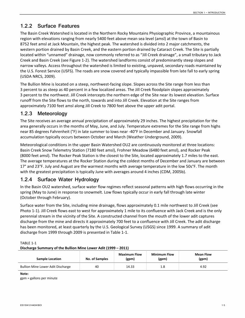
Surface water from the Site, including mine drainage, flows approximately 0.1 mile northwest to Jill Creek (see Photo 1-1). Jill Creek flows east to west for approximately 1 mile to its confluence with Jack Creek and is the only perennial stream in the vicinity of the Site. A constructed channel from the mouth of the lower adit captures discharge from the mine and directs it approximately 700 feet to a confluence with Jill Creek. The adit discharge has been monitored, at least quarterly by the U.S. Geological Survey (USGS) since 1999. A summary of adit discharge from 1999 through 2009 is presented in Table 1-1.
TABLE 1-1 Discharge Summary of the Bullion Mine Lower Adit (1999 – 2011)
Sample Location No. of Samples Maximum Flow
(gpm) Minimum Flow
(gpm) Mean Flow
(gpm)
Bullion Mine Lower Adit Discharge 40 14.33 1.8 4.92
Note: gpm = gallons per minute
ES110413144041BOI 1-5
SECTION 1 – INTRODUCTION
PHOTOGRAPH 1-1. Jill Creek Flowing through NW Portion of Bullion Mine Site
From its confluence with Jill Creek, Jack Creek flows southwest approximately 2 miles to its confluence with Basin Creek.
Jill Creek carries no specific classification, but the streams into which it flows do. The beneficial use classification for Jill Creek, Jack Creek, and Basin Creek is B-1 (in accordance with ARM 17.30.610). This classification states that the water quality of the stream must be sufficient to support recreational activities such as bathing and swimming; growth and propagation of salmonid fishes and associated aquatic life; waterfowl, furbearers, and other wildlife; agricultural and industrial water supply; and drinking, food processing, and culinary purposes (after conventional treatment). Jill Creek, by virtue of its flow contribution to Jack Creek, plays a significant role in whether Jack Creek meets its water quality criteria for achieving State B-1 classification.
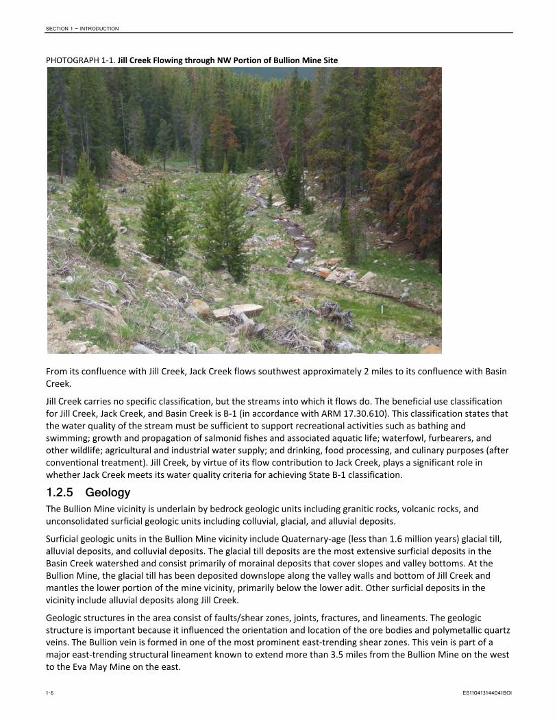
1.2.5 Geology The Bullion Mine vicinity is underlain by bedrock geologic units including granitic rocks, volcanic rocks, and unconsolidated surficial geologic units including colluvial, glacial, and alluvial deposits.
Surficial geologic units in the Bullion Mine vicinity include Quaternary-age (less than 1.6 million years) glacial till, alluvial deposits, and colluvial deposits. The glacial till deposits are the most extensive surficial deposits in the Basin Creek watershed and consist primarily of morainal deposits that cover slopes and valley bottoms. At the Bullion Mine, the glacial till has been deposited downslope along the valley walls and bottom of Jill Creek and mantles the lower portion of the mine vicinity, primarily below the lower adit. Other surficial deposits in the vicinity include alluvial deposits along Jill Creek.
Geologic structures in the area consist of faults/shear zones, joints, fractures, and lineaments. The geologic structure is important because it influenced the orientation and location of the ore bodies and polymetallic quartz veins. The Bullion vein is formed in one of the most prominent east-trending shear zones. This vein is part of a major east-trending structural lineament known to extend more than 3.5 miles from the Bullion Mine on the west to the Eva May Mine on the east.
1-6 ES110413144041BOI

CRYSTAL MINE E SITECRYSTAL MINE SITE
BULLION MINEMINEUBULLION MINE
FIGURE 1-2SITE LOCATIONBullion Mine Feasibility Study
ES062911192419BOI Fig1-2_BullionSiteLocation_v1.ai

SECTION 1 – INTRODUCTION
This page intentionally left blank.
1-8 ES110413144041BOI

SECTION 1 – INTRODUCTION
1.2.6 Hydrogeology Two general aquifers exist in the Basin Creek Watershed: a shallow, unconfined alluvial aquifer found in stream alluvium and thick colluvial deposits, and a deeper aquifer within fractured bedrock. Groundwater recharge in the vicinity of the Bullion Mine occurs from the infiltration of snowmelt and precipitation at topographic highs. Infiltration is greatest in areas with higher hydraulic conductivity, such as zones of densely fractured rock and collapsed shafts and raises. Groundwater discharge occurs as numerous springs and seeps in topographic lows, slope breaks, at geologic contacts with changes in hydraulic conductivity, and where adits daylight. Typically, crystalline bedrock aquifers have low hydraulic conductivity, except where secondary fracture permeability exists, such as along fault zones, mineralized zones, and large fractures.
In the immediate vicinity of the Bullion Mine, it appears that groundwater inflow into the tunnels and adits comes primarily from infiltration of surface water from saturated areas, fractured rocks, and old collapsed shafts and trenches above the extensive mine workings. No groundwater discharge was observed from the middle and upper Bullion adits during the 2010–2012 investigations. However, the lower Bullion adit has a pronounced perennial discharge of groundwater.
Numerous springs were observed and inventoried in the northwest part of the Site. Groundwater seeps and interflow downgradient of the Site contribute to the total metal load in Jill Creek downstream of Bullion Mine. The local hydrogeologic conditions and groundwater levels are described in more detail under “Subsurface Conditions” in the RI (CH2M HILL, 2013).
1.3 Site History Mining within the Basin Mining District began in the mid to late 1800s and continued sporadically into the 1960s. The first mining consisted of placer activities concentrated on Basin and Cataract Creeks. The first lode deposits were discovered in the 1870s with the Eva May, Crystal, Uncle Sam, Hattie Ferguson, Bullion, and the Hope/Katie mines (CDM, 2005b).
The Bullion Mine was worked periodically between 1897 and 1955, with some sporadic surface mining conducted in 1974. The smelter and a gravity concentrator were constructed in 1905. The smelter was located approximately 1 mile away, on another tributary to Jack Creek. In 1929, a flotation mill was constructed in the main development area. Approximate total production was 30,000 tons of ore containing 3,500 ounces of gold, 250,000 ounces of silver, 300 tons of copper, 1,000 tons of lead, and 1,000 tons of zinc.
Seven foundations from mining structures are scattered throughout the lower half of the Site. The majority of the foundations lie between the middle and lower adit. The Site contained several waste rock piles below the adits (these were removed in 2001), on which several buildings and ore bins were constructed. A mill with tailings and two breached tailings impoundments were also present. The upper three adits, along with most of the waste rock dumps and some of the tailings are on private land (patented mining claims).
1.4 Previous Investigations Previous sampling, RI/FSs, risk assessments, and response actions have been undertaken in the Basin Watershed OU2. Related operable units, such as the Bullion Mine (OU6), have been included in these activities; therefore, many of the results and conclusions from this previous work are pertinent to the Site. Much of the relevant information available from these studies has been incorporated into the RI report (CH2M HILL, 2011) and mentioned in this FS document. A list of relevant investigations and associated regulatory activities that have occurred at the Site can be found in Section 1.5 of the Draft Final Bullion Mine Remedial Investigation (CH2M HILL, 2013).
One of the previous investigations was a 2009 Engineering Evaluation/Cost Analysis (EE/CA) of the Bullion Mine (CH2M HILL, 2009). The purpose of the EE/CA was to evaluate various non-time-critical removal action alternatives in accordance with the National Contingency Plan in Part 40 CFR Section 300.415.
ES110413144041BOI 1-9

SECTION 1 – INTRODUCTION
The removal action alternatives for the Bullion Mine developed in the EE/CA were as follows:
• Alternative 1—No action • Alternative 2—Mine plugging and groundwater control • Alternative 3—Active treatment of AMD • Alternative 4—Semi-active treatment of AMD (quicklime injection system with Settling Ponds) • Alternative 5—Semi-passive treatment of AMD (sulfate reducing bioreactor)
No final scoring of remedial alternatives in the EECA was completed, and no final removal action was chosen or initiated for the Site. EPA decided instead to pursue a focused RI/FS and Interim ROD as a means to determine cleanup action for the Bullion Mine site.
1.4.1 Removal Actions 2001 to 2002. Time Critical Removal Action. In 2001 and 2002, a TCRA was completed at the Bullion Mine through a joint USFS–EPA initiative (Photograph 1-2). Waste was removed from approximately 8 acres (approximately 27,238 cubic yards) from the upper, middle, and lower waste rock dumps (below the three adits), and tailings from impoundments adjacent to Jill Creek. Waste materials were transported to the Luttrell Repository on the northern boundary of the watershed near the headwaters of Basin Creek. An adit discharge channel was constructed in the reclaimed area.
1.4.2 Remedial Investigation 2010-2013. Remedial Investigation, Feasibility Study, Human Health and Ecological Risk Assessment. A focused RI/FS and risk assessment of the Site was initiated by EPA in 2010 and is represented in part by this document. The RI/FS was completed in 2013.
Ongoing activities include preparation of a Proposed Plan (PP) and Record of Decision (ROD). After cleanup goals are set in the ROD, Remedial Design (RD) and Remedial Action (RA) activities will begin as the Site progresses into the remediation or clean-up phase.
1.5 Conceptual Site Model A conceptual site model was prepared for the Site to identify potential sources of metals and arsenic, and probable pathways of these contaminants from source material into soils, groundwater, and surface water (see Figures 1-3 and 1-4). The conceptual model for the Site was developed from existing data (previous investigations and Basin Watershed OU2 RI) and information obtained from 2010-2012 RI field activities. The formerly disturbed areas of the Site have been partially remediated by removal of waste rock and tailings, graded, and capped with limestone gravel and 18 to 24 inches of cover soil. Jill creek was realigned and constructed. The Site is revegetated with native grasses, forbs and seedlings. Remnant mining structures onsite include three foundations (for a mill and two unknown structures), discharging lower adit (through debris of a collapsed portal), a lined adit drainage channel, several log framed mine support structures; presence of several collapsed shafts; and several foot prints of former waste rock dumps. The model highlights the following potential contaminant source areas, site conditions, and features.
PHOTOGRAPH 1-2. Bullion Mine Adit Discharge Channel and Reclaimed Area
1-10 ES110413144041BOI

ES062911192419BOI Fig1-3_BullionMineConceptualSitePlan_v1.ai
FIGURE 1-3BULLION MINE CONCEPTUAL SITE PLAN Bullion Mine Feasibility Study
Acid mine discharge
Rock-lined adit discharge channel. Note oxidation.
Historic flotation structures
Panorama of rock-lined channel and reclaimed area.
Confluence of adit drainage channel and Jill Creek. Note deteriorated condition of creek below confluence.
Jill Creek below Bullion Mine. Note poor condition of creek and dead trees.
Sampling Jill Creek above confluence with adit drainage channel. Note clear water.
Reclaimed area and acidic
springs
Pool formed in saturated slope
Jill Creek above Bullion Mine. Note pristine conditions.
Collapsed adit cover
North
AA
A’A’
Jill Creek
Mine Adit Discharge

This page intentionally left blank.

Jill Creek
Ground water flow into Jill CreekGround water flow into Jill Creek
LEGENDGroundwater Level
Unimpacted groundwater
Acidic groundwater high in COIs
?
FIGURE 1-4BULLION MINE PROFILEBullion Mine OU6 Remedial Investigation
ES060711213019BOI Fig2-3_BullionProfile_v09.ai
Estimated water level in mine
Shallow groundwater in weathered rock
Waste rock removed in previous site action
MW-1
MW-2
MW-3
MW-4
AditInterceptBoring Historic
Tunnel No. 2(Lower)
Springs discharge acidic water high in COI’s
Blocked/collapsed adit portal
Historic Tunnel No. 4(Middle)
Historic Tunnel No. 3(Upper)
Acid mine drainage
Shallow monitoring wells
Waste rock removed in previous site action
Mined, extent of stopes and style of development unknown, mining width up to 16 feet in lower works
Water infiltrates through weathered, fractured, and mineralized host rock
Water enters mine through fractures in the bedrock, inner workings and shafts
Mineralized rock of Bullion vein
Extent of mining unknown
Waste rock removed in previous site action
A A’Precipitation and snow melt runoff infiltrate into soil and old mine tunnels and shafts
Airborne transport of soil
Residual waste rock erosion and transport
Springs discharge acidic water high in COIs
Surface erosion of sediments into Jill Creek
Through geochemical processes, ground water is converted to acidic mine drainage high in dissolved metals

This page intentionally left blank.

SECTION 1 – INTRODUCTION
1.5.1.1 Mining Waste Rock Waste rock dumps and tailings were removed from the Bullion Mine property in 2001 and 2002 as a result of a removal action performed by EPA and the USFS Northern Region. No remnants of the upper or middle adit portals are visible; although the footprint of the former waste rock dumps are still visible in spite of the applied reclamation. Residual friable rock fragments mixed in with underlying soils are present in these former dump locations. Over time, erosion and lack of a robust vegetative cover in these areas has resulted in the exposure of some of this underlying material (see Photograph 1-3). Given its sulfide and mineralized content, the potential exists for acidic leachate to form when exposed to oxygen, water, and bacteria.
1.5.1.2 Acid Mine Drainage/Acid Rock Drainage When sulfide-bearing rock is exposed to oxygen and water, the sulfide minerals undergo an oxidation reaction resulting in the creation of sulfuric acid (H2SO4). This condition occurs in underground workings as well as in waste rock and tailings. When the volume of acidic leachate exceeds the natural buffering (acid neutralizing) capacity of the host rock, AMD occurs and can result in the dissolution of metals and arsenic into surface and groundwater. Evidence of AMD can be seen in aluminum (white precipitate) and iron oxide staining (dark rust colored precipitate) commonly associated with groundwater or surface water flow paths from adit discharge or seeps, both of which are present at the Bullion Mine (see Photograph 1-4).
1.5.1.3 Contaminated Surface Water Surface water quality can be degraded by releases of contaminants from mine waste material or co-mingling with AMD. Concentration of contaminants is highly dependent on chemical release mechanisms, stream flow, and water chemistry. Degradation of surface water quality can be more severe during low flow stream condition, if the release of contaminants into the stream, from an adit for instance, remains constant. Storm events or spring runoff can erode waste rock dump material into nearby streams where sediment load and COPC dissolution contribute to water quality degradation. The Bullion Mine adversely affects Jill Creek through these mechanisms.
PHOTOGRAPH 1-3. Erosion Rill Formed through Former Waste Rock Dump Location
PHOTOGRAPH 1-4. Aluminum and Iron Oxide Staining Representative of AMD
ES110413144041BOI 1-15

SECTION 1 – INTRODUCTION
PHOTOGRAPH 1-5. Lower Adit AMD Entering Jill Creek
1.5.1.4 Contaminated Groundwater Groundwater can become contaminated through a number of physical processes. Surface water can infiltrate and migrate into underground mine workings and become degraded through its interaction with contaminant bearing host rock. Trace metal/metalloid bearing water can then migrate into adjacent bedrock aquifers, discharge as base flow into local creeks, or flow through interconnected mine workings and ground surface as an adit discharge or seeps. This represents a significant pathway at the Bullion Mine (see Figure 1-3 and Photograph 1-5). Because of its high elevation, steep slopes, and shallow soils, the Bullion Mine disturbance is more likely to influence shallow groundwater quality by snow melt or precipitation infiltrating down through the soil-bedrock interface where it flows eventually into Jill Creek.
1.5.1.5 Stream Sediments Contaminated stream sediments are often the result of direct erosion of contaminated waste rock and soils into the stream or contaminated sediment-laden runoff co-mingling with the stream. Stream sediments can also become contaminated by the precipitation of COPCs onto stream bed load and sediment in reaches where AMD intercepts the stream. Historic and recent sampling of Jill Creek demonstrated that the Bullion Mine was a source of contaminated sediment within the Jack Creek watershed (CDM, 2005a). Since completion of the removal action in 2002 and the realignment and construction of Jill Creek, direct erosion of contaminated mine waste into the creek has been mitigated; although, there does appear to be some residual contamination in overbank deposits that may re-mobilize during flooding. The formation of contaminant precipitates and biofilm on instream sediment resulting from the interaction of AMD into Jill Creek still continues.
1.6 Summary of COPC Nature and Extent Historic investigations documented contaminated soils, surface water, groundwater, and stream sediments associated with the Site. Concentrations of arsenic and other COPCs exceeded Federal and Montana Department of Environmental Quality (MDEQ) regulatory standards (for example, Circular WQB7 2004), guidelines, and published and accepted site-specific values calculated from EPA Region 8 (as needed) (CDM, 2005a). The nature and extent of contamination, as presented by historic results, is confirmed by the findings of the 2010-2012 RI.
1.6.1 Surface Water Surface water samples were collected at 5 stations including locations upstream and downstream of the Site (including the Lower Adit discharge) and 14 springs/seeps inventoried in the vicinity of the site. Springs located upgradient of the mine and in upper Jill Creek drainage (Springs 6, 8, and 9) exhibited the best water quality (less mineralization and below Human Health maximum contaminant levels (MCLs) for most constituents of interest). Spring 7 was collected from a mineralized spring and exhibits enriched arsenic, cadmium, copper, lead, and zinc concentrations. Springs 1 through 5, and 10 through 14 are topographically downgradient of the disturbed mine lands and show a more mineralized signature with COPC concentrations varying from slightly to highly elevated.
1-16 ES110413144041BOI

SECTION 1 – INTRODUCTION
Water quality in Jill Creek, above the confluence with the mine adit discharge, is significantly better than what was recorded from stations located downstream of the mine (see Figure 1-5). In general, COPC concentrations were high with a low pH in the Bullion Mine adit discharge, followed by water at Station JC-3 located immediately downstream from the confluence of the adit discharge and the creek. At the JC-3 and JC-4 stations, human health MCLs were consistently exceeded for arsenic, cadmium, lead and zinc for both sampling episodes. Aquatic life acute and chronic standards were exceeded for aluminum, arsenic, cadmium, copper, lead, and zinc.
ES110413144041BOI 1-17

SECTION 1 – INTRODUCTION
This page intentionally left blank.
1-18 ES110413144041BOI

FIGURE 1-5SURFACE AND GROUNDWATERSAMPLING LOCATIONS Bullion Mine Feasibility Study
BOI \\OWL\PROJ\EPA\408158BULLIONMINE\GIS\MAPFILES\FS_FIG1-5_WATERSAMPLING.MXD JCARR3 9/28/2011 1:11:15 PM
VICINITY MAP
Notes:1. Area of interest subject to change.2. 2009 NAIP Orthophotography
#0 #0
#0#0
#0
#0
#0#0
#0#0
#0
#0
#0
#0
#0
!.!.!.!.
!.
"/
"/ "/
"/
"/
!.
!.
!.
!.
!.
!.
JC-4
JC-3JC-2
JC-1
Adit Channel
Spring-10
Spring-8Spring-7
Spring-6
Spring-5
Spring-2
Spring-14
Spring-13
Spring-12Spring-10
Spring-11
Spring-3Spring-4
Spring-1BullionLowerAdit
MW-47455.0
MW-27537.1MW-3
7515.4
MW-17649.7
MW-57343.2
P67083.1
P57116.2
P27242.1
P47142.8
P17254.4
P37280.0
Jill Creek
U.S. Forest Service BoundaryPrivate Property
LEGEND
!. Piezometer"/ Monitoring Well#0 Adit!. Stream Sample Location#0 Spring Sample Location
Adit Discharge ChannelU.S. Forest Service BoundaryMine Claim Boundary
$0 250 500 Feet

This page intentionally left blank.
SECTION 1 – INTRODUCTION
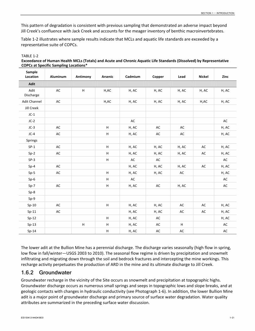
This pattern of degradation is consistent with previous sampling that demonstrated an adverse impact beyond Jill Creek’s confluence with Jack Creek and accounts for the meager inventory of benthic macroinvertebrates.
Table 1-2 illustrates where sample results indicate that MCLs and aquatic life standards are exceeded by a representative suite of COPCs.
TABLE 1-2 Exceedance of Human Health MCLs (Totals) and Acute and Chronic Aquatic Life Standards (Dissolved) by Representative COPCs at Specific Sampling Locations*
Sample Location Aluminum Antimony Arsenic Cadmium Copper Lead Nickel Zinc
Adit
Adit Discharge
AC H H,AC H, AC H, AC H, AC H, AC H, AC
Adit Channel AC H,AC H, AC H, AC H, AC H,AC H, AC
Jill Creek
JC-1
JC-2 AC AC
JC-3 AC H H, AC AC AC H, AC
JC-4 AC H H, AC AC AC H, AC
Springs
SP-1 AC H H, AC H, AC H, AC AC H, AC
Sp-2 AC H H, AC H, AC H, AC AC H, AC
SP-3 H AC AC AC
Sp-4 AC H, AC H, AC H, AC AC H, AC
Sp-5 AC H H, AC H, AC AC H, AC
Sp-6 H AC AC
Sp-7 AC H H, AC AC H, AC AC
Sp-8
Sp-9
Sp-10 AC H H, AC H, AC AC AC H, AC
Sp-11 AC H, AC H, AC AC AC H, AC
Sp-12 H H, AC AC H, AC
Sp-13 H H H, AC AC H AC
Sp-14 H H, AC AC AC AC
The lower adit at the Bullion Mine has a perennial discharge. The discharge varies seasonally (high flow in spring, low flow in fall/winter—USGS 2003 to 2010). The seasonal flow regime is driven by precipitation and snowmelt infiltrating and migrating down through the soil and bedrock fractures and intercepting the mine workings. This recharge activity perpetuates the production of ARD in the mine and its ultimate discharge to Jill Creek.
1.6.2 Groundwater Groundwater recharge in the vicinity of the Site occurs as snowmelt and precipitation at topographic highs. Groundwater discharge occurs as numerous small springs and seeps in topographic lows and slope breaks, and at geologic contacts with changes in hydraulic conductivity (see Photograph 1-6). In addition, the lower Bullion Mine adit is a major point of groundwater discharge and primary source of surface water degradation. Water quality attributes are summarized in the preceding surface water discussion.
ES110413144041BOI 1-21

SECTION 1 – INTRODUCTION
PHOTOGRAPH 1-6. Spring Discharging in the Slope of the Site near the Lower Adit
1.6.3 Waste Rock and Soils Soil samples were collected from 11 pits and 4 drilling locations within the Site. Two additional background locations were also sampled. Locations of these pits in relation to the mine workings are presented in Figures 1-6 and 1-7. Surface (0- to 2-inch depth) soil, as well as deeper soils representing the base of the reclaimed ground surface (approximately 25 to 27 inches), were obtained. A total of 73 samples were collected for elemental analysis.
As previously stated, the soils pits extended to native ground surface to document the depth of cover soils, residual waste rock, tailings or mixed soils at each location. Because the test pits were all less than 27 inches deep, soil samples were collected by hand from test pit walls. Assuming the majority of the sampling locations had an overburden of cover soil, general sampling intervals consisted of: the soil surface; two samples between the soil surface and the underlying native soil; a sample at the mine waste/top of the native soil interface; and one sample from 1 foot below the top of the native soil. In general, a total of five soil depth intervals per pit were sampled.
The interpretation of metal and arsenic concentrations in the soils took into consideration the application of clean cover soil (tested for acceptable metal concentrations) imported after removal activities were completed in 2001. Mean values of arsenic increase with sample depth, with a mean value of 860 milligrams per kilogram (mg/kg) for samples collected from the 16- to 21-inch depth. This sample increment appears to be below the imported cover soil, and thereby represents residual soil contamination remaining after the excavation of wastes and contaminated soils. Maximum concentrations of arsenic (2,290 mg/kg), copper (1,167 mg/kg), and lead (1,992 mg/kg) were also found in soils from this depth increment.
The Bullion Mine is located in a natural mineralized zone and greater concentrations of these elements are expected. Arsenic levels in soils collected from the background sites range from 16 to 107 mg/kg with a mean level of 40 mg/kg. Both the mean and maximum cover soil and the underlying wastes arsenic data exceed the background concentration not only for arsenic, but also for the other elements. This same pattern is repeated for copper, lead, manganese, nickel, and zinc concentrations. Only the minimum concentrations for cover soil are similar to the background soil levels.
1-22 ES110413144041BOI

VICINITY MAP
Notes:1. Analytical values are mg\kg2. LOD = Level of Detection
"/
"/
"/
"/
"/
"/
"/
"/
"/
"/
"/
"/
"/"/
"/
"/
"/
"/
Bullion Drill 3Depth : As : Cd : Cu : Pb : ZnNA : 657 : <LOD : 80 : 274 : 485
Bullion Drill 2Depth : As : Cd : Cu : Pb : ZnNA : 399 : <LOD : 46 : 187 : 100
Bullion Drill 5Depth : As : Cd : Cu : Pb : ZnNA : 261 : <LOD : 195 : 145 : 392
Bullion Drill 1Depth : As : Cd : Cu : Pb : ZnNA : 871 : <LOD : 195 : 512 : 324
Bullion Test Pit 10Depth : As : Cd : Cu : Pb : Zn0-2" : 15 : <LOD : <LOD : 31 : 554-6" : 26 : <LOD : 26 : 40 : 5610-12" : 98 : <LOD : 72 : 86 : 6714-16" : 15 : <LOD : <LOD : 40 : 6620-23" : <LOD : <LOD : 45 : 28 : 46
Bullion Drill 4Depth : As : Cd : Cu : Pb : ZnNA : 689 : <LOD : 138 : 397 : 273
Bullion Test Pit 4Depth : As : Cd : Cu : Pb : Zn0-2" : 61 : <LOD : 40 : 49 : 1578-10" : 21 : <LOD : 55 : 31 : 5213-15" : 10 : <LOD : 27 : 26 : 4318-20" : 11 : <LOD : 32 : 30 : 6025-27" : 260 : <LOD : 43 : 67 : 101
Bullion Test Pit 8Depth : As : Cd : Cu : Pb : Zn0-2" : 45 : <LOD : <LOD : 23 : 14424-6" : 21 : <LOD : 38 : 34 : 9927-9" : 41 : <LOD : 32 : 90 : 26010-12" : 43 : <LOD : 30 : 31 : 10417-19" : 58 : <LOD : 38 : 40 : 115
Bullion Test Pit 9Depth : As : Cd : Cu : Pb : Zn0-2" : 19 : <LOD : 50 : 46 : 1334-6" : <LOD : <LOD : 35 : 34 : 707-9" : 17 : <LOD : 34 : 28 : 6211-13" : 429 : <LOD : 90 : 185 : 38020-23" : 339 : <LOD : 91 : 131 : 309
Bullion Background 1Depth : As : Cd : Cu : Pb : Zn0-2" : 97 : <LOD : 40 : 64 : 1504-6" : 26 : <LOD : <LOD : 30 : 9510-12" : 34 : <LOD : 24 : 36 : 6716-18" : 30 : <LOD : <LOD : 29 : 4424-26" : 38 : <LOD : <LOD : 26 : 36
Bullion Test Pit 3Depth : As : Cd : Cu : Pb : Zn0-2" : 338 : <LOD : 49 : 128 : 1244-6" : 212 : <LOD : 38 : 111 : 897-9" : 475 : <LOD : 47 : 174 : 9511-13" : 968 : <LOD : 90 : 268 : 16022-24" : 364 : <LOD : 61 : 144 : 154
Bullion Test Pit 6Depth : As : Cd : Cu : Pb : Zn0-2" : 204 : <LOD : 88 : 147.0 : 2157-9" : <LOD : <LOD : 37 : 32.0 : 6314-16" : <LOD : <LOD : 29 : 31.0 : 6417-19" : <LOD : <LOD : 30 : 28.0 : 5623-25" : 59 : <LOD : 34 : 45 : 126
Bullion Test Pit 11Depth : As : Cd : Cu : Pb : Zn0-2" : 205 : <LOD : 95 : 143 : 1528-10" : 351 : <LOD : 259 : 188 : 21114-16" : 655 : <LOD : 73 : 506 : 24318-21" : 2290 : <LOD : 1167 : 1992 : 70720-23" : 255 : <LOD : 90 : 60 : 1127
Bullion Test Pit 2Depth : As : Cd : Cu : Pb : Zn0-2" : 475 : <LOD : 103 : 95 : 2278-10" : 1496 : <LOD : 223 : 192 : 46915-17" : 1655 : <LOD : 185 : 218 : 54918-19" : 554 : <LOD : 304 : 164 : 46922-24" : 2079 : <LOD : 284 : 293 : 867
Bullion Background 2Depth : As : Cd : Cu : Pb : Zn0-2" : 107 : <LOD : 37 : 38 : 954-6" : 24 : <LOD : 26 : 43 : 1098-10" : 17 : <LOD : <LOD : 32 : 7114-16" : 16 : <LOD : <LOD : 33 : 4720-22" : 21 : <LOD : 37 : 38 : 6520-22" Dup : 30 : <LOD : 39 : 32 : 61
Bullion Test Pit 1Depth : As : Cd : Cu : Pb : Zn0-2" : 58 : <LOD : 30 : 39 : 626-8" : <LOD : <LOD : 41 : 36 : 5312-13" : 835 : <LOD : 178 : 240 : 26314-15" : 1146 : <LOD : 158 : 252 : 31022-24" : 1290 : <LOD : 190 : 266 : 437
Bullion Test Pit 5Depth : As : Cd : Cu : Pb : Zn0-2" : 60 : <LOD : 110 : 49 : 2090-2" Dup : 57 : <LOD : 110 : 45 : 1914-6" : 28 : <LOD : 35 : 39.0 : 2869-11" : 25 : <LOD : 29 : 27.0 : 22912-14" : 17 : <LOD : 32 : 27.0 : 10322-24" : 131 : <LOD : 194 : 81.0 : 399
Bullion Test Pit 7Depth : As : Cd : Cu : Pb : Zn0-2" : 105 : <LOD : 42 : 94.0 : 890-2" Dup : 126 : <LOD : 47 : 111.0 : 1048-10" : 245 : <LOD : 59 : 64.0 : 11012-14" : 1616 : <LOD : 91 : 223.0 : 14816-18" : 2955 : <LOD : 78 : 318 : 12622-24" : 2198 : <LOD : 100 : 247 : 245
Jill Creek
LEGEND"/ TestPit
Adit Discharge ChannelTopographic SurveyMine Claim Boundary
0 200 400100 300
Feet
$
ES062911192419BOI Fig1-6_SoilPitsWithSamplesAnalyzedByXRF_v1.ai
FIGURE 1-6BULLION MINE SOIL PIT SAMPLINGXRF SAMPLING RESULTSBullion Mine Feasibility Study

This page intentionally left blank.

\\O
WL\
PR
OJ\
EPA
\408
158B
ULL
ION
MIN
E\G
IS\M
AP
FILE
S\A
NA
LYTI
CA
LRE
SU
LTS
SOIL
_SO
ILS
AMP
LIN
G.M
XD J
CAR
R3
1/3/
2011
14:
07:5
7
VICINITY MAP
Notes:1. Analytical values are mg\kg
"/
"/
"/
"/
"/
"/
"/
"/
"/
"/
"/
"/
"/"/
"/
"/
"/
"/
Bullion Drill 5
Bullion Drill 4
Bullion Drill 3
Bullion Drill 2
Bullion Drill 1
Bullion Test Pit 9Depth : As : Cd : Cu : Pb : Zn : pH11-13" : 324 : 5.4 : 64.6 : 135 : 274 : 7.6
Bullion Test Pit 5Depth : As : Cd : Cu : Pb : Zn : pH4-6" : 19.3 : 1.5 : 20.3 : 22.0 : 177 : 7.1
Bullion Test Pit 3Depth : As : Cd : Cu : Pb : Zn : pH7-9" : 200 : 2.4 : 32.8 : 97.7 : 65.5 : 6.8
Bullion Test Pit 8Depth : As : Cd : Cu : Pb : Zn : pH7-9" : 23.4 : 0.36 : 28.4 : 22.7 : 275 : 7.5
Bullion Test Pit 7Depth : As : Cd : Cu : Pb : Zn : pH22-23" : 2810 : 33.7 : 116 : 292 : 268 : 7.2
Bullion Test Pit 4Depth : As : Cd : Cu : Pb : Zn : pH13-15" : 5.1 : ND : 27.9 : 18.5 : 36.9 : 6.7
Bullion Test Pit 2Depth : As : Cd : Cu : Pb : Zn : pH15-17" : 1770 : 23.3 : 205 : 236 : 458 : 7.0
Bullion Test Pit 1Depth : As : Cd : Cu : Pb : Zn : pH6-8" : 2.5 : 0.062 : 26.4 : 18.5 : 42.3 : 7.5
Bullion Test Pit 11Depth : As : Cd : Cu : Pb : Zn : pH18-21" : 3090 : 45.1 : 887 : 2870 : 854 : 4.2
Bullion Test Pit 10Depth : As : Cd : Cu : Pb : Zn : pH4-6" : 15.7 : 0.28 : 27.4 : 24.7 : 39.2 : 7.7
Bullion Test Pit 6Depth : As : Cd : Cu : Pb : Zn : pH14-16" : 6.2 : 0.075 : 31.3 : 19.3 : 38.3 : 7.2
Bullion Background 1Depth : As : Cd : Cu : Pb : Zn : pH10-12" : 28.2 : 0.49 : 10.9 : 29.3 : 48.3 : 6.9
Bullion Background 2Depth : As : Cd : Cu : Pb : Zn : pH4-6" : 17.5 : 0.40 : 13.9 : 17.5 : 63.2 : 6.94-6" Dup : 18.1 : 0.40 : 18.7 : 17.0 : 63.1 : 7.1
0 200100
Feet
LEGEND"/ TestPit
Topographic SurveyMine Claim Boundary
$
FIGURE 1-7SOIL PITS WITH SAMPLES ANALYZED BY LABORATORY METHODSBullion Mine Feasibility Study
ES062911192419BOI Fig1-7_SoilPitsWithSamplesAnalyzedByLaboratoryMethods_v1.ai

This page intentionally left blank.

SECTION 1 – INTRODUCTION
Acidity in these soils and waste rock samples was determined by measuring pH. Data were transformed to hydrogen ion concentrations so that statistical calculations of mean values could be correctly determined. Mean pH levels indicate acidic soil/waste rock at a depth of 18 to 23 inches deep in the soil profile. The source of the acidity in these materials is derived from the oxidation of pyrite in the Bullion ore body.
1.6.4 Bioavailability of Arsenic and Lead in Soil As directed by EPA, a 2012 mine-specific bioavailability study was conducted to provide a better understanding of the bioavailability of arsenic and lead in selected Site soils (see Section 3.6.2 in the RI [CH2M HILL, 2013]). This information was used to more accurately assess the potential risk to human and ecological receptors. In addition, the site-specific bioavailability data are expected to support decisions on the selection of appropriate cleanup levels. A representative subset of soil samples was obtained from the larger number of soil sampling locations established during the 2010 sampling event. The chosen sampling locations were representative of the site and had previously exhibited varying concentrations of arsenic (range from 15 to 475 mg/kg) and lead (range from 23 to 147 mg/kg). A background soil sample was also selected. The range of variability for arsenic and lead bioavailability is high. The study results showed sample specific bioavailability factors below the default bioavailability value for arsenic at all selected Site soils. Lead bioavailability factors for most samples were above the default bioavailability value used for the Adult Lead Model. The Mine-specific mean bioavailability factors were approximately 22 and 19 percent for arsenic and lead, respectively. A 95 percent UCL on the mean was calculated to be 33.5 and 35.3 for arsenic and lead, respectively using the methodology described in Section 6.4.2.2 of the RI. These values were used as the site-specific bioaccessibility adjustment factors for the human health risk assessment (HHRA). The results of bioavailability studies confirm the previous assertion that the relative amount of arsenic and lead available for potential adverse effects in humans and mammals is lower than assumptions used in the risk assessment prepared for the Bullion RI. The HHRA and ecological risk assessment (ERA) account for this confirmatory information. A data summary of the bioavailability of arsenic and lead in Bullion Mine soils is provided in Appendix C of the Final RI (CH2M HILL, 2013).
1.6.5 Stream Sediments The 2001 removal action which reclaimed approximately 500 feet of Jill Creek and revegetated the area, has greatly reduced the obvious erosion issues previously associated with the Site. Barren, eroding slopes no longer intercept Jill Creek as they did prior to 2001. The current condition represents a new baseline for the Bullion Mine reach of Jill Creek. In spite of the improvements, bank erosion and over land flow remain as natural processes that contribute sediment into the creek. Stream sediment was sampled as part of the 2010-2012 RI. Six sampling sites were collocated with the previous 2010 RI macroinvertebrate survey sites. Three size fractions were differentiated and analyzed. Target analytes were aluminum, antimony, arsenic, cadmium, copper, iron, lead, manganese, nickel, selenium, silver, thallium, and zinc. The highest concentrations were generally observed in the smaller size fractions (silt/clay), which is consistent in sediment results. However, for each sample, the smallest size fraction represents the smallest percentage by weight of the sample. The sediment concentrations were highest at Station Jill-2, located immediately downstream of the confluence of Jill Creek and the Bullion adit flow. Concentrations of antimony, arsenic, cadmium, copper, iron lead, manganese, selenium, silver, and zinc all exceeded freshwater sediment screening benchmarks. The results of the sediment sampling confirm the findings from the previous Basin Watershed OU2 RI (CDM, 2005b) that enriched metalloid and trace metal concentrations occur in stream sediments from the Bullion Mine to its’ confluence with Jack Creek. Today, the primary degradation of water quality, within the Jill Creek tributary to Jack Creek is the discharge of AMD from the Bullion Mine, which is the focus of this report.
1.6.6 Macroinvertebrate Survey To perform a benthic macroinvertebrate survey, monitoring stations were established at four locations on Jill Creek bracketing the Site and two locations on Jack Creek (see Figure 1-8).
The results of the survey data clearly show impacts from AMD and toxic pollutants originating from the Bullion Mine. A sparse, but relatively diverse macroinvertebrate assemblage was present above the Site. Downstream from the mine discharge, Jill Creek was essentially devoid of life. The few macroinvertebrates collected
ES110413144041BOI 1-27

SECTION 1 – INTRODUCTION
downstream from the adit had probably recently drifted into the reach from upstream. Measurable impacts extended downstream into Jack Creek.
Both Jack and Jill Creeks are impacted streams, with poor to fair benthic habitat. Macroinvertebrates were scarce throughout the study area. Only 1,301 organisms were collected during this survey. Nevertheless, several hundred macroinvertebrates were collected at each site in upper Jill Creek and in Jack Creek above the Jill Creek confluence. These sites supported diverse assemblages dominated by stoneflies and mayflies. Taxa considered sensitive to AMD were present at each site. In contrast, only 12 macroinvertebrates were collected from Jill Creek downstream from the Bullion Mine discharge. Impacts from AMD were also evident in Jack Creek below the confluence of Jill Creek. Macroinvertebrate density and taxa richness were reduced, and community composition shifted to more tolerant species in Jack Creek below Jill Creek compared to the Site approximately 80 meters upstream.
Data from Jill-1, Jill-2, and Jack-6 can be used as references for evaluating biological recovery at downstream sites. While these sites are not pristine, they support relatively robust macroinvertebrate faunas that are characteristic of least impaired streams in the region.
1.6.7 Wetlands From the top to the bottom of its major watercourses, the Site is approximately 0.5 mile long (approximately 2,400 feet) and averages 0.1 mile wide (approximately 600 feet). The wetland areas appear in the northwest portion of the Site.
On the basis of 2010 field work, it was determined that approximately 2.6 acres of the 40-acre the Site were delineated as jurisdictional wetland (see Table 1-3). Given the degree of historic disturbance of the Site and the recent efforts at revegetation, however, the Bullion Mine is best characterized as a mixed matrix of wetlands and uplands, with wetland and upland status varying mostly because of subtle differences in elevation relative to groundwater.
Within the remediated portion of the Site are 2.1 acres of jurisdictional wetlands scattered across the reclaimed hillside.
The jurisdictional wetland acres are those regulated by the United States Army Corps of Engineers, that meet the three criteria for a wetland (hydric soils, hydrophytic vegetation and wetland hydrology), and are connected or adjacent to a water of the United States. These wetlands are also subject to the “no net loss” requirement of Executive Order 11990, and remedial actions performed at the Site must avoid impacting functional wetlands.
Figure 1-9 shows Jill Creek and the lower seep area. The purple line surrounds the jurisdictional wetland boundaries.
Thirty-one different plant species were found in the wetland transects of the Bullion Mine (see Table 5 in the original text from ESG, Bullion RI document Appendix H). Nineteen species were rated as being facultative wetland plants, nine species were rated as being upland plants, and two species were not rated. Seventeen species were woody (both overstory and understory), and 14 species were herbaceous.
TABLE 1-3 Jurisdictional Wetland Acres Observed on the Bullion Mine Survey Area
Jurisdictional Wetland Acres
Wetland along the reclaimed area 2.1
Jill Creek and lower seep area 0.5
Total 2.6
1-28 ES110413144041BOI

VICINITY MAP
Notes:1. Area of interest subject to change.2. 2009 NAIP Orthophoto
#7#7
#7
#7
#7#7
Jack-6
Jack-5
Jill-4
Jill-3
Jill-1Jill-2
Jill Creek
Jack
Cree
k
0 500250
Feet
LEGEND#7 Macro-Invertebrate Sampling Location
NHD StreamMine Claim Boundary
$
ES062911192419BOI Fig1-8_BenthicMacro-InvertebrateMonitoring Locations_v1_v1.ai
FIGURE 1-8BENTHIC MACRO-INVERTEBRATE MONITORING LOCATIONSBullion Mine Feasibility Study

This page intentionally left blank.

SECTION 1 – INTRODUCTION
FIGURE 1-9 Wetlands along Jill Creek and Lower Seep Area
1.6.8 Threatened and Endangered Species A survey of U.S. Fish and Wildlife Service (USFWS) information and Montana Natural Heritage Program data were reviewed to identify potential threatened and endangered species potentially using or living within the vicinity of the Site. Only the following currently-listed threatened and endangered species have a realistic potential of being at or near the Bullion Mine: Canada lynx (2010), wolverine, and grizzly bear (2013). As of this writing is should be noted that in 2011 Congress formally delisted the gray wolf.
1.7 Summary of Human Health and Ecological Risk Evaluation 1.7.1 Introduction An HHRA and ERA was conducted at the Bullion Mine and in accordance with applicable Montana Department of Environmental Quality (MDEQ) and EPA guidance. The resulting characterization of potential risk is expected to provide enough information for informed decisions at the Bullion Mine. The primary decision for which the results of the risk assessment provide input is whether to develop remedial alternatives for any areas and COPCs at the Site because of the potential threat of human health or ecological risk. Based on the exposure assumptions used in the Bullion RI (Section 6), the findings are presented in the following text.
ES110413144041BOI 1-31

SECTION 1 – INTRODUCTION
1.7.2 Human Health Risks were estimated for the most plausible pathways of human exposure, based on reasonably anticipated land and water uses at Bullion Mine. These exposure scenarios included current and intermittent workers, recreational users, and future excavation worker receptor groups. In addition, unrestricted use was evaluated using hypothetical future standard industrial worker exposure scenario.
1.7.2.1 Intermittent Workers Current and future intermittent workers were evaluated for potential exposure to COPCs detected in surface soil (0 to 10 inches below ground surface [bgs]). Cumulative excess lifetime cancer risk (ELCR) estimates using the reasonable maximum exposure (RME) and central tendency exposure (CTE) scenarios are within the EPA target risk range of 1 × 10⁻⁶ to 1 × 10⁻⁴, and below the MDEQ statutory risk level of 1 × 10⁻⁵. Hazard Index (HI) estimates were below the EPA and MDEQ threshold value of 1 for this exposure scenario.
No contaminants of concern (COCs) are identified for the intermittent worker RME exposure scenario based on the ELCR and HI estimates.
1.7.2.2 Recreational Users Surface Soil. Current and future adult and adolescent recreational users were evaluated for potential exposure to COPCs detected in surface soil (0 to 10 inches bgs). The recreational user scenarios assume predominant use by ATV riders. Risk estimates are driven by the dust inhalation pathway and would overestimate the risk for other recreational users (for example, hikers). Considering this, risk estimates for the intermittent worker scenario are likely more representative of most recreationalists (for example, hikers). Cumulative ELCR estimates using the RME assumptions are within the EPA target risk range of 1 × 10⁻⁶ to 1 × 10⁻⁴, and exceed the MDEQ statutory risk level of 1 × 10⁻⁵. HI estimates above the EPA and MDEQ threshold value of 1 were also identified for these exposure scenarios.
Arsenic was identified as the only COC for recreational users RME exposure scenario. No exceedances were identified using CTE assumptions.
Surface Water. Current and future adult and adolescent recreational users were also evaluated for potential exposure to COPCs detected in surface water. Cumulative ELCR estimates using the RME and CTE assumptions are within the EPA target risk range of 1 × 10⁻⁶ to 1 × 10⁻⁴, and exceed the MDEQ statutory risk level of 1 × 10⁻⁵. HI estimates were below the EPA and MDEQ threshold value of 1 for these exposure scenarios.
Arsenic was identified as the only COC for recreational users.
1.7.2.3 Excavation Workers Future excavation workers users were evaluated for potential exposure to COPCs detected in subsurface soil (0 to 10 feet bgs). Cumulative ELCR estimates using the RME and CTE scenarios are within the EPA target risk range of 1 × 10⁻⁶ to 1 × 10⁻⁴, and do not exceed the MDEQ statutory risk level of 1 × 10⁻⁵. HI estimates are below the EPA and MDEQ threshold value of 1 for this exposure scenario.
No COCs are identified for the excavation worker exposure scenario based on the ELCR and HI estimates.
1.7.2.4 Hypothetical Industrial Workers Hypothetical standard (default) industrial workers were evaluated for potential exposure to COPCs detected in surface soil (0 to 10 inches bgs). Cumulative ELCR estimates using the RME and CTE scenarios are within the EPA target risk range of 1 × 10⁻⁶ to 1 × 10⁻⁴, and the RME scenario exceeds the MDEQ statutory risk level of 1 × 10⁻⁵. HI estimates are below the EPA and MDEQ threshold value of 1 for this exposure scenario.
Arsenic is the only COC identified for the hypothetical industrial worker exposure scenarios based on the ELCR and HI estimates.
1-32 ES110413144041BOI
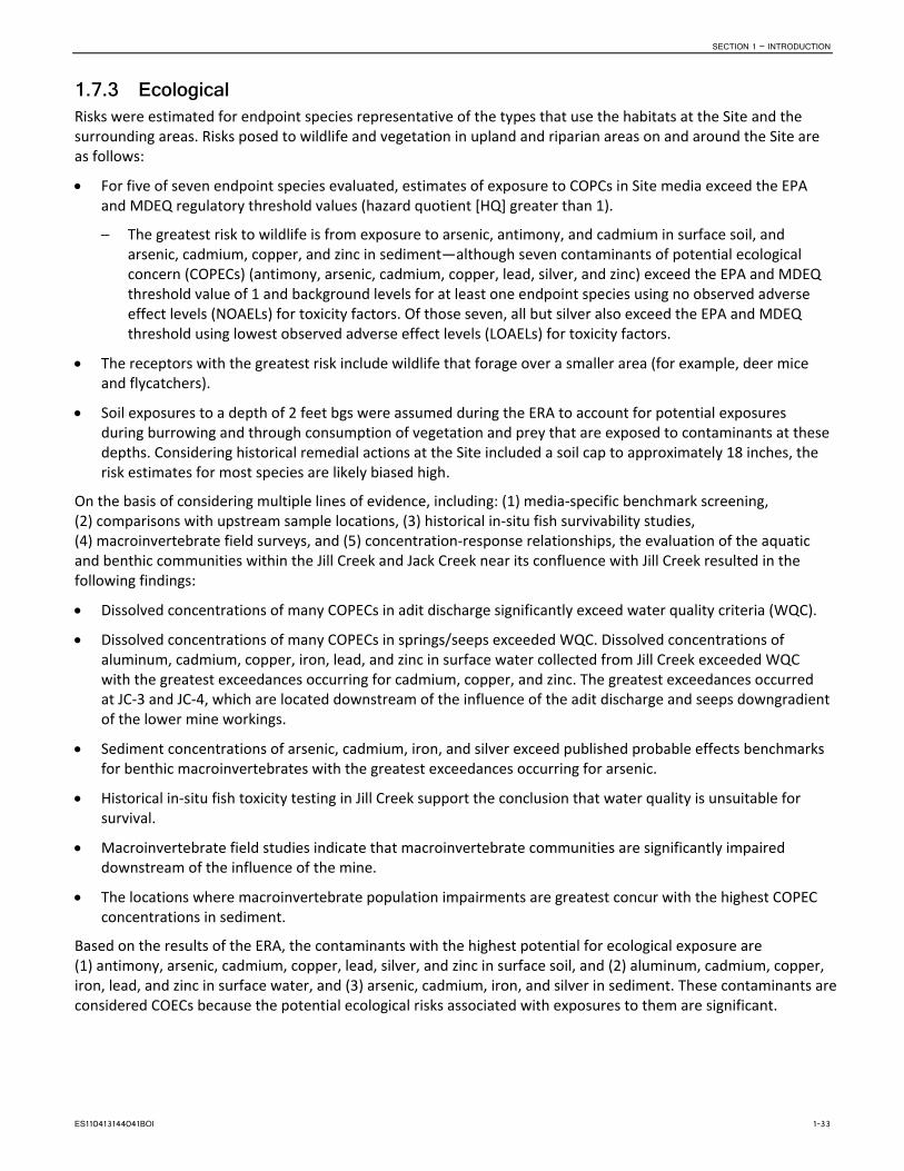
SECTION 1 – INTRODUCTION
1.7.3 Ecological Risks were estimated for endpoint species representative of the types that use the habitats at the Site and the surrounding areas. Risks posed to wildlife and vegetation in upland and riparian areas on and around the Site are as follows:
• For five of seven endpoint species evaluated, estimates of exposure to COPCs in Site media exceed the EPA and MDEQ regulatory threshold values (hazard quotient [HQ] greater than 1).
─ The greatest risk to wildlife is from exposure to arsenic, antimony, and cadmium in surface soil, and arsenic, cadmium, copper, and zinc in sediment—although seven contaminants of potential ecological concern (COPECs) (antimony, arsenic, cadmium, copper, lead, silver, and zinc) exceed the EPA and MDEQ threshold value of 1 and background levels for at least one endpoint species using no observed adverse effect levels (NOAELs) for toxicity factors. Of those seven, all but silver also exceed the EPA and MDEQ threshold using lowest observed adverse effect levels (LOAELs) for toxicity factors.
• The receptors with the greatest risk include wildlife that forage over a smaller area (for example, deer mice and flycatchers).
• Soil exposures to a depth of 2 feet bgs were assumed during the ERA to account for potential exposures during burrowing and through consumption of vegetation and prey that are exposed to contaminants at these depths. Considering historical remedial actions at the Site included a soil cap to approximately 18 inches, the risk estimates for most species are likely biased high.
On the basis of considering multiple lines of evidence, including: (1) media-specific benchmark screening, (2) comparisons with upstream sample locations, (3) historical in-situ fish survivability studies, (4) macroinvertebrate field surveys, and (5) concentration-response relationships, the evaluation of the aquatic and benthic communities within the Jill Creek and Jack Creek near its confluence with Jill Creek resulted in the following findings:
• Dissolved concentrations of many COPECs in adit discharge significantly exceed water quality criteria (WQC).
• Dissolved concentrations of many COPECs in springs/seeps exceeded WQC. Dissolved concentrations of aluminum, cadmium, copper, iron, lead, and zinc in surface water collected from Jill Creek exceeded WQC with the greatest exceedances occurring for cadmium, copper, and zinc. The greatest exceedances occurred at JC-3 and JC-4, which are located downstream of the influence of the adit discharge and seeps downgradient of the lower mine workings.
• Sediment concentrations of arsenic, cadmium, iron, and silver exceed published probable effects benchmarks for benthic macroinvertebrates with the greatest exceedances occurring for arsenic.
• Historical in-situ fish toxicity testing in Jill Creek support the conclusion that water quality is unsuitable for survival.
• Macroinvertebrate field studies indicate that macroinvertebrate communities are significantly impaired downstream of the influence of the mine.
• The locations where macroinvertebrate population impairments are greatest concur with the highest COPEC concentrations in sediment.
Based on the results of the ERA, the contaminants with the highest potential for ecological exposure are (1) antimony, arsenic, cadmium, copper, lead, silver, and zinc in surface soil, and (2) aluminum, cadmium, copper, iron, lead, and zinc in surface water, and (3) arsenic, cadmium, iron, and silver in sediment. These contaminants are considered COECs because the potential ecological risks associated with exposures to them are significant.
ES110413144041BOI 1-33

SECTION 1 – INTRODUCTION
1.7.4 Contaminants of Concern The Site was previously evaluated as part of a watershed-wide RI/FS and risk assessment process (Basin Watershed OU2). As such, COPCs were already evaluated for the Site through a baseline ecological risk assessment (BERA) for the Basin Watershed OU2 (CDM, 2002). The Basin Watershed OU2 risk assessment identified the primary COCs that drive the risk to human health and the environment at the Site as arsenic, cadmium, copper, lead, and zinc (EPA, 2000). Using the previous Basin Watershed OU2 risk assessment findings, site-specific historic investigation findings, and the knowledge that the Site has been inactive since those findings, the focused RI prepared a list of metals and metalloids (COI) to evaluate for nature and extent of contamination at the Bullion Mine.
Based on the findings of the risk assessment (CH2M HILL, 2013), which used a weight-of-evidence approach, multiple lines of evidence support the conclusion that exposure to COCs in Site media pose an unacceptable risk to human health and the environment. Arsenic in soils is the only COC identified for potential human health exposures. The contaminants with the highest potential for ecological exposure are: (1) antimony, arsenic, cadmium, copper, lead, silver, and zinc in surface soil; (2) aluminum, arsenic, cadmium, copper, iron, lead, nickel, and zinc in surface water (includes all contaminants that exceed Circular DEQ-7 Standards), and (3) arsenic, cadmium, iron, and silver in sediment. Therefore, the RI recommended that these metals be carried forward to the FS to determine whether remedial alternatives are necessary to address these risks. Other collocated contaminants, not identified in the RI for specific action, will be addressed by the eventual remedial action selected.
1.8 Conclusions of the RI The nature and extent of contamination at the Site have been adequately characterized in the 2010 through 2012 sampling activities and prior investigations. EPA’s Time Critical Removal Action in 2001 and 2002 removed contaminated soils to an approximate depth of two feet. On the basis of results from the Bullion RI report and risk assessment, the following media will be considered for potential remedial alternatives in the FS:
• Groundwater expressed as an adit discharge from the lower workings of the Bullion Mine, and shallow groundwater expressed at seeps/springs between the discharging adit and Jill Creek.
• Surface soils at the Bullion Mine
─ For human health exposure to soil—maintenance of the existing cap by placement of debris or some other method to discourage ATV use, and selective amendment of soils where such cover is inadequate.
─ For ecological exposure to soil – The ERA assumes exposures to 2 feet (below the cover) and unacceptable risk is likely only for small burrowing animals.
• Sediment in streams adjacent to and down-gradient of the Bullion Mine—For ecological exposure, sediment in the streams poses a high risk to wildlife, aquatic life, and benthic organisms.
1-34 ES110413144041BOI

2. Remedial Action Goals and Screening of Technologies
2.1 Introduction 2.1.1 Remedial Action Objectives A goal of this focused RI/FS process is to define the nature and extent of contamination at the Site and develop appropriate remedial alternatives for selection as an interim action in accordance with CERCLA criteria. Alternatives must contribute to protection of human health and the environment, ARARs compliance, and rank highly when evaluated against the following additional seven criteria: long-term effectiveness and permanence; reduction of toxicity, mobility and volume through treatment; short-term effectiveness; implementability; cost; state acceptability; and community acceptability.
Preliminary remedial action objectives (PRAOs) and preliminary remediation goals (PRGs) for the Bullion Mine are proposed in the followings sections. The general cleanup objectives and goals identified in this FS are common for cleanup actions at abandoned hard rock mine sites. As site-specific information becomes available during the RI/FS, the PRAOs and PRGs are refined. Final RAOs and final remediation action limits will be identified in the record of decision (ROD) for the Site.
2.1.2 Applicable or Relevant and Appropriate Requirements Section 121 of CERCLA, the NCP (40 CFR Part 300), and guidance and policy statements issued by the EPA require that interim remedial actions contribute to compliance with ARARs. These ARARs are threshold standards that any selected remedy must meet during and upon completion of the remedial action. A requirement under environmental laws may be either “applicable” or “relevant and appropriate” to site-specific remedial action, but not both. Identification of ARARs must be done on a site-specific basis and the FS must determine whether a given requirement is applicable, relevant and appropriate, or to be considered (TBC).
Applicable requirements refer to those cleanup standards, standards of control, and other substantive environmental protection requirements, criteria or limitations under federal or state law that specifically address hazardous substances, pollutants, contaminants, remedial actions, locations, or other circumstances found at a CERCLA site.
Relevant and appropriate requirements are those cleanup standards, standards of control, and other substantive requirements under federal environmental or state environmental citing laws that, while not “applicable” to hazardous substances, pollutants, contaminants, remedial actions, locations, or other circumstances at a CERCLA site, address problems or situations sufficiently similar to those encountered at a CERCLA site that their use is well suited to the particular site.
The NCP identifies three classifications of ARARs: chemical-specific; action-specific; and location-specific. As part of the focused RI/FS, potential federal and state ARARs are identified. A draft summary of potential ARARs is provided in Appendix A. Potential chemical-, action-, and location-specific requirements for the Site are as follows:
• Chemical-Specific ARARs. Federal and state health or risk based numeric standards that are promulgated for site-specific media. They represent the maximum allowable concentration of a chemical that may remain onsite and still protect against unacceptable risks to human health and the environment. Chemical specific ARARs exist for surface water and groundwater, but do not exist for waste rock, tailings, soils, or sediments.
• Action-Specific ARARs. Technology or activity based requirements or limitations on remedial actions taken with respect to hazardous waste. These requirements are triggered by the selection of particular remedial activities.
ES110413144041BOI 2-1

SECTION 2 – REMEDIAL ACTION GOALS AND SCREENING OF TECHNOLOGIES
• Location-Specific ARARs. Statutory or regulatory restrictions on the management of hazardous substances or on the conduct of remedial activities in specific locations. Locations of special interest include: flood plains, wetlands, historic and culturally sensitive places, and sensitive ecosystems and habitats.
It should be noted, however, that the scope of this focused FS is limited to the Site and will be used to develop an Interim ROD. As previously discussed, the Site is located within the 77-square-mile Basin Watershed OU2. Remedial alternatives retained in the focused FS are chosen for their ability to mitigate human health and ecological risk associated with the Site media. Implementation of preferred remedial alternatives will contribute to the overall compliance with ARARs for the Basin Watershed OU2. A complete assessment of ARAR compliance will be performed when a record of decision for the entire Basin Watershed (OU2) is prepared.
2.1.3 Preliminary Remedial Action Objectives PRAOs are media-specific objectives for protecting human health and the environment. They address various chemicals of concern, media of concern, exposure pathways and receptors, current and likely future land and water uses. Proposed PRAOs for the Site, as defined by the EPA, are discussed in the following text.
2.1.3.1 Groundwater Because of the limited occurrence of groundwater at this high altitude mountain Site, the nature and extent of shallow groundwater throughout the Site was evaluated with shallow monitoring wells and piezometers. Groundwater infiltrating through the bedrock fractures and into the underground workings and discharging from the lower adit as acid mine drainage was also evaluated. This discharge presently intercepts and degrades Jill Creek which flows into Jack Creek and eventually the Boulder River. Proposed PRAOs for groundwater are as follows:
• Groundwater infiltrates through the bedrock fractures into the underground mine workings. Methods for diverting source water from the mine workings will be considered, if practical.
• Prevent or minimize groundwater discharge containing COCs such that surface water standards can be met in Basin Creek.
• Minimize concentrations of COCs in Site groundwater such that state groundwater standards can be met for the Basin Watershed OU2.
• Formal groundwater quality objectives will be determined by the Basin Watershed OU2 remedy. In the interim, remedial action at the Site will strive to achieve Montana groundwater quality standards to the extent practicable.
2.1.3.2 Surface Water MDEQ classifies water quality in Basin Creek as a B1 stream. This classification states that the water quality of the stream must be sufficient to support recreational activities such as bathing and swimming; growth and propagation of salmonid fishes and associated aquatic life; waterfowl, furbearers, and other wildlife; agricultural and industrial water supply; and drinking, food processing, and culinary purposes (after conventional treatment).
From a human health standpoint, Jack Creek does not currently meet the requirements for suitable drinking, culinary and food processing use. Basin Creek appears on MDEQ’s 303(d) list for the following water quality parameters that exceeded standards aluminum, arsenic, copper, lead, mercury, and zinc. Jack Creek is not currently listed on a Montana 303(d) list but will be listed in 2014 for the same constituents. Total maximum daily loads (TMDLs) have been developed by MDEQ and approved by the EPA in December, 2012. Because of these characteristics, the surface water PRAOs proposed for Jack and Jill Creeks are as follows:
• Surface water infiltrates through the bedrock fractures into the underground mine workings. Methods for diverting source water from reaching the mine workings will be considered, if practical.
• Prevent or minimize release of COCs to surface waters that result in unacceptable dermal and incidental risks for visitors and recreationists.
2-2 ES110413144041BOI

SECTION 2 – REMEDIAL ACTION GOALS AND SCREENING OF TECHNOLOGIES
• Prevent or minimize release of COCs to surface waters that result in unacceptable risks to terrestrial and aquatic species.
2.1.3.3 Soils The nature and extent of mine waste and impacted soils at the Bullion Mine are defined by the RI and are mitigated by a previous removal action and a vegetated soil cover. Subsurface soils, below the soil cover or exposed by erosion of the cover material, remain contaminated with significant concentrations of COCs. The PRAO for these media in areas where the soil cap is compromised by erosion, are as follows:
• Prevent or minimize human exposure to soils/waste rock contaminated with COCs where incidental ingestion, dust inhalation, or direct contact would pose an unacceptable health risk.
• Prevent or minimize unacceptable risk to ecological systems (including aquatic and terrestrial) from contaminated waste rock/soils containing elevated levels of metals (antimony, arsenic, cadmium, copper, lead, silver, and zinc).
2.1.3.4 Stream Sediments The nature and extent of contaminated sediments in Jill Creek is delineated in the RI and represent considerable exposure to ecological receptors. However, since implementation of the time-critical removal action (TCRA), which remediated the hillsides adjacent to the creek and reconstructed the creek channel, remediation of stream sediments will rely on annual spring runoff and local thunderstorms to mitigate minor residual-contaminated bank deposits by natural burial and mixing after the direct mine discharge is eliminated. Annual monitoring of stream sediment deposits, prior to its confluence with Jack Creek, will track the success of this method. The PRAO for sediments is as follows:
• Prevent or minimize unacceptable risk to ecological systems (including aquatic and terrestrial) degraded by contaminated sediment containing elevated levels of metals (arsenic, cadmium, iron, and silver). Prevent or minimize further migration of mine site contaminated source materials or discharges in close proximity to the creek.
2.1.4 Preliminary Remediation Goals Preliminary remediation goals (PRGs) are media-specific contaminant concentrations that are considered protective of human health and the environment given the possibility of exposures to human or ecological receptors. Contaminant-specific PRGs also consider the available ARARs for the Site. The PRGs for human health and the environment are developed for each of the identified COCs using the same exposure assumptions as used in the baseline risk assessment for the Site. The PRGs proposed in this document serve as guidelines. Final remediation levels will be selected by EPA after review of available data and information including final risk assessment documents, anticipated effectiveness of proposed cleanup alternatives, and other remedy selection criteria such as public and state preferences. PRGs proposed for surface water, groundwater, sediment, and soils for the Site are presented in the following text.
2.1.4.1 Groundwater The PRG for groundwater are based on the MDEQ Circular DEQ-7 (2012) standards (see Table 2-1). The proposed PRG for groundwater is as follows:
• Formal groundwater quality goals will be determined by the Basin Watershed OU2 remedy. In the interim, remedial action at the Site will strive to achieve Montana groundwater quality standards to the extent practicable.
2.1.4.2 Surface Water PRGs for surface water are based on Montana’s water quality standards, defined in MDEQ Circular DEQ-7 (2012). The surface water PRGs are intended to provide for potential surface water use in compliance with State B1 classification at the confluence of Jill Creek and Jack Creek. If human health drinking water standards and aquatic life standards exist for the same contaminant, the more restrictive of the standards will be used as the State’s surface water quality cleanup standard. The PRGs for surface water are as follows:
ES110413144041BOI 2-3

SECTION 2 – REMEDIAL ACTION GOALS AND SCREENING OF TECHNOLOGIES
• MCLs or state human health standards for all COCs downstream of the confluence of Jill Creek and Jack Creek.
• Acute and chronic aquatic life criteria for all COCs in surface water downstream of the confluence of Jill Creek and Jack Creek.
Table 2-1 identifies the State of Montana Water Quality Standards for both surface and groundwater. These standards are to be the PRGs for Jill Creek downstream of the Site. Table 2-1 also identifies the National Surface Water Quality standards. The State of Montana surface water standards are to be the primary PRGs for Jill Creek downstream of the Site. The National Surface Water Quality standards are to be supplementary PRGs to the State of Montana standards.
TABLE 2-1 Montana Water Quality Standards and National Surface Water Quality Criteria
Analyte
State of Montana Standards 2
National Recommended Water Quality Criteria—
Aquatic Life3,c
EPA Surface Water1
Human Health Standards Aquatic Life
Acute Chronic Surface Water Groundwater Acute Chronic
Aluminum —- —- 0.75 0.087 0.75 0.087 0.087
Antimony 0.0056 0.006 —- —- —- —- 0.03
Arsenic 0.01 0.01 0.34 0.15 0.34 0.15 0.005
Cadmium 0.005 0.005 0.00052 0.000097 0.0008a 0.00012a 0.00025
Copper 1.3 1.3 0.00379 0.00285 0.0052a 0.0038a 0.009
Iron —- —- —- 1 —- —- 0.3
Lead 0.015 0.015 0.01398 0.000545 0.021a 0.0008a 0.0025
Manganese —- —- —- —- —- —- 0.12
Nickel 0.1 0.1 0.145 0.0161 0.20a 0.022a 0.052
Selenium 0.05 0.05 0.02 0.005 —- 0.0050b 0.001
Silver 0.1 0.1 0.000374 —- 0.0032a —- 0.0032
Thallium 0.00024 0.002 —- —- —- —- 0.0008
Zinc 2 2 0.037 0.037 0.05a 0.05a 0.12
Notes: 1 EPA Freshwater Screen Benchmarks (milligrams per liter [mg/L]) (2012). Available at
http://www.epa.gov/reg3hwmd/risk/eco/btag/sbv/fw/screenbench.htm. 2 DEQ-7 Montana Numeric Water Quality Standards (MDEQ, 2012) Freshwater standards from EPA (2009), National Recommended Water Quality Criteria for Priority Pollutants. a The freshwater criterion for this metal is expressed as a function of hardness (mg/L) in the water column. The value given here
corresponds to the minimum hardness reported in Uncle Sam Gulch of 36.6 mg/l as CaCO3 (Data source: USGS Station 461904112144401 [mouth of Uncle Sam Gulch], 1998 – 2007). Criteria values for other hardness may be calculated from the following:
CMC (dissolved) = exp(mA[ln(hardness)]+bA) (CF), or CCC (dissolved) exp (mC[ln(hardness)] + bC) (CF) b This recommended water quality criterion for selenium is expressed in terms of total recoverable metal in the water column. It is
scientifically acceptable to use the conversion factor (0.996 – CMC or 0.922 – CCC) that was used in the GLI (60 FR 15393-15399, March 23, 1995; 40 CFR 132 Appendix A) to convert this to a value that is expressed in terms of dissolved metal.
c Metals are stated as dissolved unless otherwise specified. Units are all reported in mg/L
2-4 ES110413144041BOI

SECTION 2 – REMEDIAL ACTION GOALS AND SCREENING OF TECHNOLOGIES
2.1.4.3 Stream Sediments The PRGs for COCs in stream sediments in Jill Creek address potential risks to benthic infaunal communities, and are provided in Table 2-2. These PRGs are derived from upper probable effects concentrations (PECs) from the sources listed in the table. Sediment PRGs protective of recreational users or wildlife from exposure to Site COCs are the same as those provided for soil, presented in the next subsection. No active remediation is proposed to achieve these goals. As explained under the PRAOs, stream sediment quality is expected to improve through natural recovery after remedial actions for the contaminant source (for example, mine adit discharge and shallow groundwater).
TABLE 2-2 Sediment Preliminary Remediation Goals for Benthic Infauna
Sediment COC Units
Upper Effects Concentrations/
Cleanup Screening Levels Source
Arsenic mg/kg 33.0 McDonald, et al 2000
Cadmium mg/kg 5.4 McDonald, et al 2000
Copper mg/kg 149 McDonald, et al 2000
Lead mg/kg 128 McDonald, et al 2000
Nickel mg/kg 48.6 McDonald, et al 2000
Zinc mg/kg 459 McDonald, et al 2000
2.1.4.4 Soils The PRGs for mine waste and soils address potential risks to Site workers, recreational visitors, and wildlife from exposure to Site COCs. Potential exposure is limited to small areas where erosion has compromised the soil cap placed during the TCRA and to wildlife species that may burrow or consume food items below the soil cap. The PRGs for soils at the Site are as follows:
• Achieve exposure risks to recreationist and workers in the acceptable risk range of 10-4 to 10-6 or less. • Achieve cleanup levels below which ecological risks are acceptable.
Human health PRGs for soil are derived for arsenic—the only COC identified. Details regarding the exposure assumptions for these potentially exposed populations are presented in the RI Report. Note: Current and future land use identified during the RI for the Site indicated that residential use is not practical. Children potentially using the site are expected to be old enough to use ATVs, hunt, etc. (i.e., adolescents). This was determined on the basis of considering the lack of nearby residences and the steep topography, surface obstacles, and remoteness of the site.
The approach and equations used for calculating PRGs for arsenic are consistent with EPA guidance in Risk Assessment Guidance for Superfund—Volume I: Human Health Evaluation Manual (Part B: Development of Risk-Based Preliminary Remedial Goals) (EPA, 1991). PRGs are calculated using RME assumptions and for the range of risks allowed by CERCLA regulations: ELCR = 10-6, 10-5, and 10-4, and HQ = 1. Table 2-3 presents the PRGs derived for arsenic.
ES110413144041BOI 2-5

SECTION 2 – REMEDIAL ACTION GOALS AND SCREENING OF TECHNOLOGIES
TABLE 2-3 Soil Arsenic Preliminary Remediation Goals for Human Health
Exposure Scenario
Preliminary Remediation Goal for Arsenic (mg/kg)
ELCR=1 × 10⁻⁶ ELCR=1 × 10⁻⁵ ELCR=1 × 10⁻⁴ HQ=1
RME CTE RME CTE RME CTE RME CTE
Recreational User – Adult (ATV User Scenario) 12 195 115 1,947 1,154 19,466 390 3,547
Recreational User – Adolescent (ATV User Scenario) 21 337 214 3,369 2,142 33,687 311 2,708
Recreational User – Adult (non-ATV; e.g., Hiker) 29 424 285 4,237 2,851 42,374 4.375 32,545
Recreational User – Adolescent (non-ATV; e.g., Hiker) 30 440 296 4,397 2,959 43,972 1,139 8,470
Excavation Worker 82 1,079 817 10,789 8,173 107,892 3,458 6,917
Hypothetical Industrial Worker 11 86 114 861 1,138 8,609 1,813 3,590
Notes: Arsenic Background Range = 16 to 107 mg/kg ELCR = excess lifetime cancer risk HQ = noncancer hazard quotient RME = Reasonable Maximum Exposure CTE = Central Tendency Exposure
The lowest human health PRGs are for recreational user scenarios that assume all-terrain vehicle (ATV) riding occurs regularly at the Bullion Mine. Boggy areas, steep slopes and large debris (rocks and down trees) likely reduce the ATV activities across the Bullion Mine. The risk from this scenario (described in the RI) is largely driven by exposure through inhalation. During the RI, a more conservative particulate emissions factor (PEF) for ATV users was assumed than the standard PEF since this activity has the potential to increase dust entrainment. A PEF of 8.47 x 10⁵ m3/kg for this scenario derived for EPA Region 8 (SRC, 2009) was applied for both the RME and CTE scenarios. EPA’s default PEF of 1.36 x 10⁹ m3/kg was used for all other exposure scenarios. To account for potential land use restrictions or remedial designs that would significantly reduce or prevent ATV use, PRGs were calculated for recreational users using EPA’s default PEF. These levels are intended to be protective of recreationalists that are not regularly using ATVs at the Bullion Mine (for example, hikers).
Ecological PRGs for mine waste, soil, and dust are derived for aluminum, antimony, arsenic, cadmium, copper, lead, selenium, silver, and zinc, which were the COCs identified (Table 2-4). PRGs are developed for the wildlife species determined to be most sensitive to each COC, as documented in the BERA of the RI Report, and represent toxicity levels ranging from the NOAEL to the LOAEL. Since some of the toxicity-based PRGs listed are within the range of natural levels in soil, the background levels for each of the COCs are also provided in Table 2-4.
TABLE 2-4 Soil/Sediment Preliminary Remediation Goals for Wildlife
COPEC Endpoint Species NOAEL-based PRG
(mg/kg) LOAEL-based PRG
(mg/kg) Soil Background
(mg/kg)
Antimony Deer mouse 1.05 10.5 0.35U to 125U
Arsenic Deer mouse 11 185 16 to 107
Cadmium Dusky flycatcher 1.1 2.02 0.4 to 0.49
Copper Dusky flycatcher 45.5 52 10.9 to 39
Lead Dusky flycatcher 21.5 26.5 17 to 64
Silver Dusky flycatcher 6.0 60 0.38U
Zinc Dusky flycatcher 110 114 36 to 150
NOAEL = No observed adverse effects levels LOAEL = Lowest observed adverse effects levels
2-6 ES110413144041BOI

SECTION 2 – REMEDIAL ACTION GOALS AND SCREENING OF TECHNOLOGIES
2.2 Identification and Screening of General Response Actions, Technology Types and Process Options
2.2.1 Introduction The first step in developing remedial alternatives, following or concurrent with the development of remedial action objectives, requires the identification of likely response scenarios. Using the terminology that is laid out in the EPA Guidance for Conducting Remedial Investigations and Feasibility Studies under CERCLA (EPA, 1988), these are called general response actions (GRAs). GRAs are media-specific measures that may satisfy the remedial action objectives alone or in combination.
During the development of alternatives, an initial determination is made of areas or volumes of media to which a GRA might be applied. Defining areas or volumes of media should include consideration of acceptable exposure levels and potential exposure routes, as well as site conditions and nature and extent of contamination. To account for interaction between media, response actions for areas or volumes of media are later refined after site wide alternatives are defined and considered.
Potential treatment, resource recovery, and containment technologies that will accomplish these measures are proposed subsequent to the identification of GRAs.
“In this step, the universe of potentially applicable technology types and process options is reduced by evaluating the options with respect to technical implementability.” (EPA, 1998)
Following the identification and screening of remedial technologies, representative process options are selected to represent the remedial technology through alternative development and analyses. Process options, on a medium-specific basis and relative to specific GRAs, are screened using effectiveness, implementability, and cost.
At this stage in the development of alternative, remedial technologies and process options may still be retained that would not necessarily meet effectiveness requirements for all media, the full site, or as standalone technologies (EPA, 1998).
2.2.2 General Response Actions The media to be addressed at the Bullion Mine are surface water (primarily adit discharge), and shallow groundwater. Contaminated soils and mining waste at the Bullion Mine site were the subject of a joint removal action by the USFS (Region 1) and the USEPA (Region 8). A description of activities associated with the soil removal and reclamation of this site can be found in the Final Construction report – Bullion Mine and Millsite Removal Action, Jefferson County, Montana (Maxim Technologies Inc., 2003). A total of approximately 27, 238 cubic yards of waste material were excavated and transported to the Luttrel Repository. Upon completion of soil confirmation sampling, phosphate and limestone were spread over the removal areas at rates calculated from analytical laboratory results of acid-base accounting analysis. Reconstruction of the Jill Creek stream channel (approximately 500 feet) was performed concurrently with excavation of the lower waste dump and erosion deposits.
Arsenic and lead were identified as contaminants that posed possible human health risks. Metals concentrations in waste rock and native soil were compared to Risk Based Cleanup Guidelines for Abandoned Mine Sites (Tetra Tech, 1996), which were conservative soil cleanup guidelines for recreational visitors:
Average Mine Waste Metals Concentrations and Cleanup Guidelines Bullion Mine and Millsite Investigation
Average Concentration (milligrams per kilogram)
Arsenic Cadmium Copper Lead Mercury Zinc
Human Health Guideline - Soil exposure
700 19,500 27,100 1,100 220 220,000
ES110413144041BOI 2-7
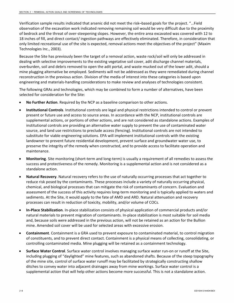
SECTION 2 – REMEDIAL ACTION GOALS AND SCREENING OF TECHNOLOGIES
Verification sample results indicated that arsenic did not meet the risk–based goals for the project. “…Field observation of the excavation work indicated removing remaining soil would be very difficult due to the proximity of bedrock and the threat of over-steepening slopes. However, the entire area excavated was covered with 12 to 18 inches of fill, and direct contact/ ingestion pathways are effectively eliminated. Therefore, in consideration that only limited recreational use of the site is expected, removal actions meet the objectives of the project” (Maxim Technologies Inc., 2003).
Because the Site has previously been the target of a removal action, waste rock/soil will only be addressed in dealing with selective improvements to the existing vegetative soil cover, adit discharge channel materials, overburden, soil and debris removed to open the adit portal, and waste mucked out of the lower adit, should a mine plugging alternative be employed. Sediments will not be addressed as they were remediated during channel reconstruction in the previous action. Division of the media of interest into these categories is based upon engineering and materials-handling considerations to make review and analyses of technologies consistent.
The following GRAs and technologies, which may be combined to form a number of alternatives, have been selected for consideration for the Site:
• No Further Action. Required by the NCP as a baseline comparison to other actions.
• Institutional Controls. Institutional controls are legal and physical restrictions intended to control or prevent present or future use and access to source areas. In accordance with the NCP, institutional controls are supplemental actions, or portions of other actions, and are not considered as standalone actions. Examples of institutional controls are providing an alternative water supply to prevent the use of contaminated water source, and land use restrictions to preclude access (fencing). Institutional controls are not intended to substitute for viable engineering solutions. EPA will implement institutional controls with the existing landowner to prevent future residential development, prevent surface and groundwater water use, to preserve the integrity of the remedy when constructed, and to provide access to facilitate operation and maintenance.
• Monitoring. Site monitoring (short-term and long-term) is usually a requirement of all remedies to assess the success and protectiveness of the remedy. Monitoring is a supplemental action and is not considered as a standalone action.
• Natural Recovery. Natural recovery refers to the use of naturally occurring processes that act together to reduce risk posed by the contaminants. These processes include a variety of naturally occurring physical, chemical, and biological processes that can mitigate the risk of contaminants of concern. Evaluation and assessment of the success of this activity requires long-term monitoring and is typically applied to waters and sediments. At the Site, it would apply to the fate of AMD and ARD. Natural attenuation and recovery processes can result in reduction of toxicity, mobility, and/or volume of COCs.
• In-Place Stabilization. In-place stabilization consists of physical application of commercial products and/or natural materials to prevent migration of contaminants. In-place stabilization is most suitable for soil media and, because soils were addressed in the previous action, will not be retained as an action for the Bullion mine. Amended soil cover will be used for selected areas with excessive erosion.
• Containment. Containment is a GRA used to prevent exposure to contaminated material, to control migration of constituents, and to prevent direct contact. Containment is a physical means of collecting, consolidating, or controlling contaminated media. Mine plugging will be retained as a containment technology.
• Surface Water Control. Surface water control involves managing surface water run-on or runoff at the Site, including plugging of “daylighted” mine features, such as abandoned shafts. Because of the steep topography of the mine site, control of surface water runoff may be facilitated by strategically constructing shallow ditches to convey water into adjacent drainages away from mine workings. Surface water control is a supplemental action that will help other actions become more successful. This is not a standalone action.
2-8 ES110413144041BOI

SECTION 2 – REMEDIAL ACTION GOALS AND SCREENING OF TECHNOLOGIES
• Groundwater Control. Groundwater control involves managing shallow groundwater near the discharging lower adit. Groundwater controls are retained as a supplementary action to several alternatives.
• Removal/Transport/Disposal and Reclamation. A complete or partial removal of source material from the Site to an approved offsite repository, with restoration or reclamation of the affected area. Because a removal action previously occurred at the Site, waste rock/soil will only be addressed in dealing with selective improvements to the existing vegetative soil cover, adit discharge channel materials, soil and debris removed to open the adit portal, and waste mucked out of the lower adit, should a mine plugging alternative be employed.
• Treatment. Treatment technologies involve the physical, chemical, or biological measures applied to source materials or contaminated media that reduce toxicity, mobility, and/or volume of contaminants present. All potential treatments would include collection of AMD currently stored within the mine behind the existing soil/debris plug, and continually discharging from the lower adit of the Bullion Mine. Potential treatment technologies to mitigate AMD would include the following:
─ Active Treatment. Employs a high density sludge treatment plant or comparable technology, a standard technology for treating AMD.
─ Semi-Active Treatment. Uses injection of quicklime to treat AMD.
─ Semi-Passive Treatment. Consists of a series of ponds to treat AMD through pH adjustment, sulfate reduction, and clarification.
The final treatment approach may include a combination of two or more treatment strategies. Treatment is retained for further consideration.
Table 2-5 presents the ten GRAs listed above with applicable site media, remedial technology, and process options.
TABLE 2-5 General Response Actions and Technologies for Surface Water, Groundwater, and Soils
Media General Response
Action Technology Process Option Retained for Evaluation
SW/GW/WR/S No further action No further action Not applicable Yes
SW/GW/WR/S Institutional controls
Access restrictions Physical barriers and signage *
Land use restrictions Deed restrictions to development of land or water
*
SW/GW/WR/S Monitoring Monitoring Short-term *
Long-term *
SW/GW Natural recovery Natural process application
Physical, chemical, and biological process
*
SW/GW Treatment Active treatment Conventional AMD treatment plant
Yes
Semi-active treatment Quick lime injection system Yes
Semi-passive treatment Sulfate-reducing bioreactor Yes
S In-place stabilization
Soil cover Amended soil cover for select areas
*
Phytostabilization Vegetation /cover supplement to former waste rock locations
*
ES110413144041BOI 2-9
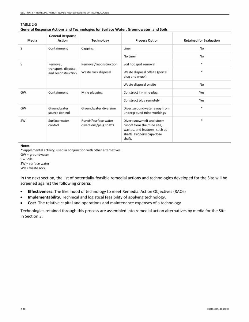
SECTION 2 – REMEDIAL ACTION GOALS AND SCREENING OF TECHNOLOGIES
TABLE 2-5 General Response Actions and Technologies for Surface Water, Groundwater, and Soils
Media General Response
Action Technology Process Option Retained for Evaluation
S Containment Capping Liner No
No Liner No
S Removal, transport, dispose, and reconstruction
Removal/reconstruction Soil hot spot removal *
Waste rock disposal Waste disposal offsite (portal plug and muck)
*
Waste disposal onsite No
GW Containment Mine plugging Construct in-mine plug Yes
Construct plug remotely Yes
GW Groundwater source control
Groundwater diversion Divert groundwater away from underground mine workings
*
SW Surface water control
Runoff/surface water diversions/plug shafts
Divert snowmelt and storm runoff from the mine site, wastes, and features, such as shafts. Properly cap/close shaft.
*
Notes: *Supplemental activity, used in conjunction with other alternatives. GW = groundwater S = Soils SW = surface water WR = waste rock
In the next section, the list of potentially-feasible remedial actions and technologies developed for the Site will be screened against the following criteria:
• Effectiveness. The likelihood of technology to meet Remedial Action Objectives (RAOs) • Implementability. Technical and logistical feasibility of applying technology. • Cost. The relative capital and operations and maintenance expenses of a technology
Technologies retained through this process are assembled into remedial action alternatives by media for the Site in Section 3.
2-10 ES110413144041BOI

3. Development and Screening of Initial Alternatives
3.1 Screening of Initial Alternatives In this section, the GRAs, remedial technologies, and process options retained after initial screening in Section 2.3 are combined into remedial alternatives. These alternatives represent viable approaches to remedial action at the Bullion Mine. As a first step, the action, technologies, and options retained from Section 2.3 are further screened for use in combinations as remedial alternatives. Then the common elements that would be incorporated into multiple alternatives (except no further action) are developed. Media-specific remedial alternatives are developed that address the individual media of concern at the Bullion Mine. Then, the media-specific techniques are assembled into combined-media remedial alternatives. Alternatives developed to span the range of categories defined by the NCP are as follows:
• No Further Action alternative. Site remains as is. No remedial action is applied to the Site.
• Groundwater source control actions. Alternatives that address the source of recharge into the mine workings or the conduit for AMD mobility through the mine.
• Groundwater response actions. Remedial alternatives that attain site-specific remediation levels within different restoration time periods utilizing one or more different technologies.
• Innovative treatment technologies. Those technologies that offer the potential for comparable or superior performance or implementability; fewer or less adverse impacts than other available approaches; or lower costs for similar levels of performance than demonstrated treatment technologies.
3.2 Common Elements In addition to institutional controls and monitoring activities, remedial actions are likely to include the following common elements:
• Removal, treatment, and discharge of existing mine water pool upstream of the blocked adit. Clear soil/debris plug to facilitate free flowing of mine water.
• Source water control will be limited spatially to activities that can be implemented within the boundaries of the operable unit (mine claims). Source water control alternatives that could be applied outside the OU6 boundaries will be considered for the Basin Watershed OU2 ROD.
During the RI for this site, source water recharge (groundwater and surface water) into the mine workings was investigated through construction of monitoring well networks, piezometers, test pits, aquifer testing, and geophysical testing. Results of these activities were incorporated into evaluations of potential interception activities (for example, horizontal drilling, new upgradient adit construction with infiltration galleries, slurry cut-off walls, and dewatering through pumping and drainage ditch arrays) with the conclusion being that a majority of the source water intercepts the mine workings through a myriad of interconnected bedrock fractures. The recharge area was determined to be extensive and impracticable to intercept given the prevalence of fractured, mineralized intrusions, and multiple faults and secondary fractures. EPA and the State of Montana recognize that complete control of source water is not technically practicable in these highly fractured bedrock systems, and long-term treatment will be required to mitigate ongoing adit discharge. Both EPA and the State share the goal of conducting a timely, efficient, and effective remedy. For these reasons, source water control efforts for this interim ROD will be limited to those which are technically practicable to implement, and represent a reasonably expected clear net benefit when compared to cost, as described below:
ES110413144041BOI 3-1

SECTION 3 – DEVELOPMENT AND SCREENING OF INITIAL ALTERNATIVES
Phase 1 • Review existing information and confirm extent of mine workings on the existing mine maps. Look for
additional information on the extent of the mine workings. Take note of specific mine features not observed during the RI that may have “daylighted” or created a surface expression that would allow water to enter the workings.
• Perform a final site reconnaissance to find, identify, and map “daylighted” mine workings that could potentially act as a conduit for surface water into the mine. Utilize information obtained during the RI process to assist with the reconnaissance.
• Identify strategic locations for drainage ditches to capture and convey snowmelt and rainfall away from areas above the underground workings.
Phase 2 • Design seals for mine features identified in Phase 1.
• Design ditches that quickly and efficiently convey snowmelt and storm runoff away from areas above the underground workings and into adjacent drainages to limit ponding and infiltration.
Phase 3 • Construct surface seals and ditches.
• Continue to monitor lower adit discharge to gage impact on flow.
Phase 4 • Design and construct an appropriate treatment system, using flow rates adjusted after source water
control actions have been implemented.
• Implement surface water controls by collecting adit discharge and contaminated surface water downgradient of the lower adit.
• Implement groundwater controls by diverting or intercepting shallow groundwater flow downgradient of the lower adit.
Most alternatives share some common elements in their development. To avoid repetition, the common elements are described in this section and then referenced in the various alternatives. Common elements are included in alternative cost estimates.
3.2.1 Adit Discharge—Dewatering, Collection and Conveyance Water is currently pooled behind the soil/debris plug forming the collapsed portal in the lower adit. This stockpile of water and the plug materials will need to be removed and disposed of before other activities can be implemented to capture the perennial adit discharge.
Water pooled within the mine will be pumped from the lower adit, treated to adjust pH, and discharged into Jill Creek (up to 2.5 million gallons). After dewatering, the soil and debris forming the portal plug will be removed and hauled to the local repository (Luttrell) for disposal. The portal will be stabilized to facilitate the free flow of water from the mine. Annual discharging mine water will be channeled into one of the following discharge collection systems. Prior to its release to Jill Creek, adit discharge would be collected and conveyed to the selected treatment system.
Two concepts for collecting the adit discharge are considered—a diversion structure at the bottom of the existing discharge channel and a collection basin at the mouth of the adit (see Figure 3-1).
3-2 ES110413144041BOI

SECTION 3 – DEVELOPMENT AND SCREENING OF INITIAL ALTERNATIVES
3.2.1.1 Diversion Structure Prior to its confluence with Jill Creek, adit discharge would be captured by a control structure at the downgradient end of the adit discharge channel (see Figure 3-2). The control structure would be wider than the adit drainage channel to control all the adit drainage and divert it to a 12-inch-diameter drain pipe inside the upstream wall of the structure. The collected adit discharge would flow to the bottom of the diversion structure where it would flow into another drain pipe on the downstream side of the diversion structure. That pipe would convey the collected adit discharge to the implemented treatment system. The diversion structure would be fitted with a locking metal lid to allow for periodic cleaning and maintenance.
3.2.1.2 Collection Basin Immediately after discharge from the adit portal AMD would be collected in a lined basin at the location of the percolation basin built as part of the previous action in 2001 (see Figure 3-3). The basin would collect AMD discharging from the adit mouth and convey it through a solid pipe into the treatment system. Although USGS records of flows from 1999 to 2008 show a very constant discharge rate, the basin would be sized to allow for some storage (approximately 24 hours of flow) to accommodate peaks in discharge flow rate. Therefore, the treatment system will be designed for constant flow. This alternative would reuse the existing discharge channel as a pipe trench after removing and disposing of the liner and riprap.
3.2.2 Contaminated Groundwater Control Contaminated shallow groundwater discharge downgradient of the Site at Jill Creek was identified and measured during the 2003 and 2004 Montana State University (MSU) investigation. Data collected from Jill Creek during the 2003 and 2004 MSU research indicate substantial discharge of shallow contaminated groundwater to surface water, in addition to contaminated flow from the adit. Therefore, implementation of several proposed Alternatives (see Section 3.3) would incorporate a shallow groundwater collection feature upgradient of Jill Creek (see Figure 3-1).
In order to keep shallow contaminated groundwater from reaching Jill Creek, an interception trench and French drain would be constructed downgradient of the Bullion Mine (see Figure 3-4). The drain would run south of, and parallel to, Jill Creek for approximately 250 feet. For cost estimating purposes, it was assumed that the French drain would be constructed at approximately 6 feet below grade with a groundwater collector pipe running at the bottom. The 6-inch-diameter polyvinyl chloride (PVC) collector pipe would be perforated along the entire length and then transition to solid-walled pipe prior to discharging into the treatment system. For estimating purposes it was assumed that the drain would be 6 feet deep and 4 feet wide with a geotextile liner, washed gravel, and a perforated collection pipe that transitions to solid at the end of the trench to convey water to treatment.
3.2.3 Waste Rock Removal As described in Section 1.2.2, during the 2002 Bullion Mine Reclamation Project, the drainage channel from the lower adit of the Bullion Mine to its confluence with Jill Creek was lined with PVC and layered with riprap (see Photograph 1-5). Since installation, no further actions have taken place and the riprap has formed an outer “iron oxide armoring” layer as a result of the AMD passing over it.
A common element included in the groundwater alternatives is the reconditioning or replacement of the drainage channel, depending on which adit discharge control alternative is used. Armored riprap from the channel will be collected and hauled to the Luttrell Repository for disposal. Under the diversion structure approach, new riprap will be placed back in the channel. Under the collection basin approach, the channel would be used as a pipe trench and backfilled.
ES110413144041BOI 3-3

SECTION 3 – DEVELOPMENT AND SCREENING OF INITIAL ALTERNATIVES
This page intentionally left blank.
3-4 ES110413144041BOI

FIGURE 3-1 ADIT DISCHARGE COLLECTION OPTIONSBullion Mine Feasibility Study
North
Adit Discharge Dam
Bullion Mine Discharge Collection Basin
12 Inch Pipe
6 Inch Perforated Pipe
0 300
Approximate scale in feet
100 200
B
B
ADIT DISCHARGE DAM
RHYOLITE + 6” HDPE PIPE
BULLION MINEC
C
A
A
ES062911192419BOI Fig3-1_BullionAditDischargeCollectionOptions_v1.ai

SECTION 3 – DEVELOPMENT AND SCREENING OF INITIAL ALTERNATIVES
This page intentionally left blank.
3-6 ES110413144041BOI

DIVERSION STRUCTURE
STEEL PLATE LID
OVERFLOW PIPE
12” DIA INLET
12” OUTLET
ES062911192419BOI Fig3-2_DischargeChannelDiversionStruct_v1.ai
FIGURE 3-2DISCHARGE CHANNEL DIVERSION STRUCTUREBullion Mine Feasibility Study
JILL CREEK
50’65’
DIVERSIONSTRUCTURE,SEE DETAIL BELOW
BULLION ADIT DISCHARGE CHANNEL
7140
7120
7100
EXISTING GRADE
SECTION A-A 0 4020
Approximate scale in feet
4’8’

SECTION 3 – DEVELOPMENT AND SCREENING OF INITIAL ALTERNATIVES
This page intentionally left blank.
3-8 ES110413144041BOI

ES062911192419BOI Fig3-3_CollectionBasinDetail_v2 .ai
FIGURE 3-3COLLECTION BASIN DETAILBullion Mine Feasibility Study
SECTION B-BNOT TO SCALE
RHYOLITE
ADIT
BULLION ADIT DISCHARGE CHANNEL
GROUNDWATER/SURFACE CUTOFF
COLLECTION BASIN
JILL CREEK
COLLECTION BASIN DETAILNOT TO SCALE
6” HDPE
ADIT
15’

SECTION 3 – DEVELOPMENT AND SCREENING OF INITIAL ALTERNATIVES
This page intentionally left blank.
3-10 ES110413144041BOI

ES062911192419BOI Fig3-4_GWCutoff_v2.ai
FIGURE 3-4GROUNDWATER CUT-OFF Bullion Mine Feasibility Study
6” PERFORATEDDRAIN PIPE
GROUNDWATER
DRAIN ROCK
6” BULLION MINE DISCHARGE PIPE
SURFACE WATER
GEOFABRIC
GROUNDWATER CUT-OFF NOT TO SCALE
SECTION C-C0 4020
Approximate scale in feet
25’42’42’
JILL CREEK
GROUNDWATER
SURFACE WATER EXISTING GRADE7120
7108
GROUNDWATER CUT-OFF, SEE DETAIL BELOW
6’

SECTION 3 – DEVELOPMENT AND SCREENING OF INITIAL ALTERNATIVES
This page intentionally left blank.
3-12 ES110413144041BOI
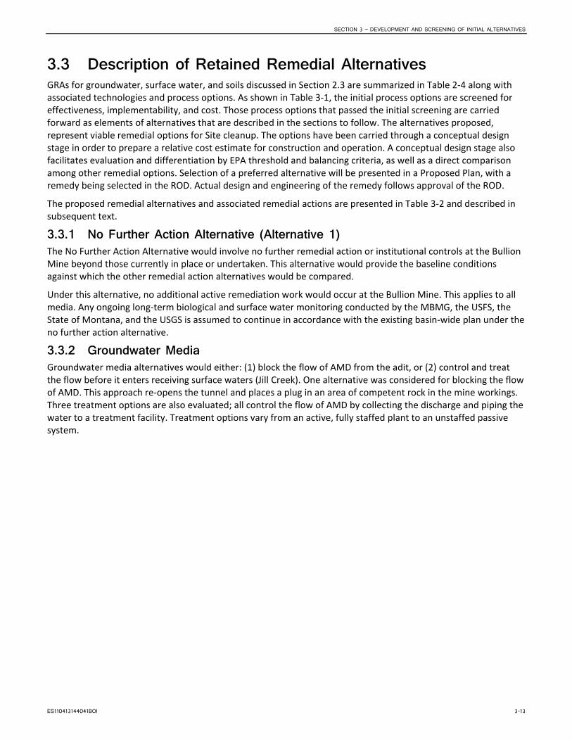
SECTION 3 – DEVELOPMENT AND SCREENING OF INITIAL ALTERNATIVES
3.3 Description of Retained Remedial Alternatives GRAs for groundwater, surface water, and soils discussed in Section 2.3 are summarized in Table 2-4 along with associated technologies and process options. As shown in Table 3-1, the initial process options are screened for effectiveness, implementability, and cost. Those process options that passed the initial screening are carried forward as elements of alternatives that are described in the sections to follow. The alternatives proposed, represent viable remedial options for Site cleanup. The options have been carried through a conceptual design stage in order to prepare a relative cost estimate for construction and operation. A conceptual design stage also facilitates evaluation and differentiation by EPA threshold and balancing criteria, as well as a direct comparison among other remedial options. Selection of a preferred alternative will be presented in a Proposed Plan, with a remedy being selected in the ROD. Actual design and engineering of the remedy follows approval of the ROD.
The proposed remedial alternatives and associated remedial actions are presented in Table 3-2 and described in subsequent text.
3.3.1 No Further Action Alternative (Alternative 1) The No Further Action Alternative would involve no further remedial action or institutional controls at the Bullion Mine beyond those currently in place or undertaken. This alternative would provide the baseline conditions against which the other remedial action alternatives would be compared.
Under this alternative, no additional active remediation work would occur at the Bullion Mine. This applies to all media. Any ongoing long-term biological and surface water monitoring conducted by the MBMG, the USFS, the State of Montana, and the USGS is assumed to continue in accordance with the existing basin-wide plan under the no further action alternative.
3.3.2 Groundwater Media Groundwater media alternatives would either: (1) block the flow of AMD from the adit, or (2) control and treat the flow before it enters receiving surface waters (Jill Creek). One alternative was considered for blocking the flow of AMD. This approach re-opens the tunnel and places a plug in an area of competent rock in the mine workings. Three treatment options are also evaluated; all control the flow of AMD by collecting the discharge and piping the water to a treatment facility. Treatment options vary from an active, fully staffed plant to an unstaffed passive system.
ES110413144041BOI 3-13

SECTION 3 – DEVELOPMENT AND SCREENING OF INITIAL ALTERNATIVES
TABLE 3-1 Initial Screening of Technologies and Response Actions
General Response Actions
Remedial Technologies Process Options Description Screening Comments
No further action No action Not applicable No Action Required by NCP
Institutional controls
Access restrictions
Physical barriers and signage Installation of security fencing Applicable only as temporary measure or as part of other remedial actions
Land use restrictions Deed restrictions on development of land or water
Retained as a measure of all other remedial actions
Monitoring Monitoring Short-term Monitor during remedy implementation Retained.
Long-term Monitor post-remedy implementation Retained.
Natural recovery Attenuation Physical, chemical, biological process
Use natural process for Site cleanup Low cost. Easy to implement. Not effective at addressing PRAOs.
In-place stabilization
Soil Cover Amended soil cover Amended top soil cover over waste rock to allow for revegetation
Moderate cost. Easy to implement. Not effective at addressing PRAOs.
Phytostabilization Phytoremediation applied to waste rock
Chemical additives added to waste rock to neutralize pH and allow for revegetation
Moderate cost. Moderate ease of implementation. Not effective because of short growing season, lack of organic materials in waste rock, lack of State acceptance
Containment Mine plugging Engineered plug in mine Re-open mine and build plug Moderate to high cost. Moderate to difficult implementation. Moderate to high effectiveness. Potentially applicable. Retained.
Engineered plug remote grouting
Inject concrete slurry through drilled borings to plug
High cost. Moderate to difficult implementation. Effectiveness uncertain.
Surface water controls
Grading Site grading to control surface water runoff Retained.
Revegetation Control soil erosion Retained.
Water Control Overland flow control
Diversion Construction of a diversion structure to control surface water drainage in the vicinity of the lower adit, including berms and check dams
Retained.
Groundwater control
Interception Construction of a groundwater cut-off wall to control shallow groundwater flows
Retained.
Treatment Active treatment Conventional AMD treatment plant
Conventional high-density sludge (HDS) treatment plant (or comparable treatment)
Moderate to high cost. Moderate implementation. Highly effective. High maintenance. Retained.
Semi-active treatment
Quicklime injection system Installation of water-wheel lime injection system and treatment ponds
Moderate to high cost. Moderate implementation. Moderate to high effectiveness. Moderate to high maintenance. Retained.
Semi-passive treatment
Sulfate reducing bioreactor (SRBR)
Installation of SRBR and settling ponds Low to moderate cost. Moderate to difficult implementation. Moderate effectiveness. Moderate to low maintenance. Retained.
Note: Gray font indicates technologies screened out.
3-14 ES110413144041BOI
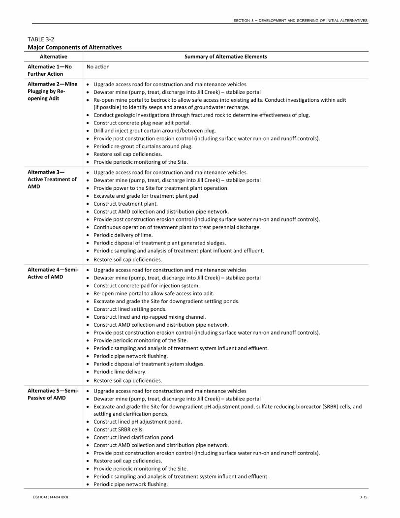
SECTION 3 – DEVELOPMENT AND SCREENING OF INITIAL ALTERNATIVES
TABLE 3-2 Major Components of Alternatives
Alternative Summary of Alternative Elements
Alternative 1—No Further Action
No action
Alternative 2—Mine Plugging by Re-opening Adit
• Upgrade access road for construction and maintenance vehicles • Dewater mine (pump, treat, discharge into Jill Creek) – stabilize portal • Re-open mine portal to bedrock to allow safe access into existing adits. Conduct investigations within adit
(if possible) to identify seeps and areas of groundwater recharge. • Conduct geologic investigations through fractured rock to determine effectiveness of plug. • Construct concrete plug near adit portal. • Drill and inject grout curtain around/between plug. • Provide post construction erosion control (including surface water run-on and runoff controls). • Periodic re-grout of curtains around plug. • Restore soil cap deficiencies. • Provide periodic monitoring of the Site.
Alternative 3—Active Treatment of AMD
• Upgrade access road for construction and maintenance vehicles. • Dewater mine (pump, treat, discharge into Jill Creek) – stabilize portal • Provide power to the Site for treatment plant operation. • Excavate and grade for treatment plant pad. • Construct treatment plant. • Construct AMD collection and distribution pipe network. • Provide post construction erosion control (including surface water run-on and runoff controls). • Continuous operation of treatment plant to treat perennial discharge. • Periodic delivery of lime. • Periodic disposal of treatment plant generated sludges. • Periodic sampling and analysis of treatment plant influent and effluent. • Restore soil cap deficiencies.
Alternative 4—Semi-Active of AMD
• Upgrade access road for construction and maintenance vehicles • Dewater mine (pump, treat, discharge into Jill Creek) – stabilize portal • Construct concrete pad for injection system. • Re-open mine portal to allow safe access into adit. • Excavate and grade the Site for downgradient settling ponds. • Construct lined settling ponds. • Construct lined and rip-rapped mixing channel. • Construct AMD collection and distribution pipe network. • Provide post construction erosion control (including surface water run-on and runoff controls). • Provide periodic monitoring of the Site. • Periodic sampling and analysis of treatment system influent and effluent. • Periodic pipe network flushing. • Periodic disposal of treatment system sludges. • Periodic lime delivery. • Restore soil cap deficiencies.
Alternative 5—Semi-Passive of AMD
• Upgrade access road for construction and maintenance vehicles • Dewater mine (pump, treat, discharge into Jill Creek) – stabilize portal • Excavate and grade the Site for downgradient pH adjustment pond, sulfate reducing bioreactor (SRBR) cells, and
settling and clarification ponds. • Construct lined pH adjustment pond. • Construct SRBR cells. • Construct lined clarification pond. • Construct AMD collection and distribution pipe network. • Provide post construction erosion control (including surface water run-on and runoff controls). • Restore soil cap deficiencies. • Provide periodic monitoring of the Site. • Periodic sampling and analysis of treatment system influent and effluent. • Periodic pipe network flushing.
ES110413144041BOI 3-15

SECTION 3 – DEVELOPMENT AND SCREENING OF INITIAL ALTERNATIVES
TABLE 3-2 Major Components of Alternatives
Alternative Summary of Alternative Elements • Rototill pH adjustment pond approximately every 2 years. • Replace pH adjustment pond approximately every 6 years. • Replace SRBR cells approximately every 15 years. • Periodic collection and disposal of treatment system sludges.
3.3.2.1 Alternative 2—Mine Plugging by Re-opening Mine Adit The three semi-permanent mine plugging techniques (SME, 1992) that were evaluated as part of this alternative are as follows:
• Dry plug—placing suitable material, such as cement block, at the portal of the mine
• Wet plug—prevents air from entering adit, but allows water to discharge through the plug, similar to a water trap in a sink
• Hydraulic plug—placing a plug within a mine to prevent water from discharging
Of these three common permanent plug types, only a hydraulic plug would be viable for Bullion Mine. A dry plug would likely fail from high hydraulic head forming on the backside of the plug. A wet plug would allow mine drainage containing high concentrations of COCs to pass through the plug without treatment prior to discharging into streams (SME, 1992). A hydraulic plug would minimize the flow of groundwater from the mine. The resulting flooding behind the plug would also prevent air from entering the mine through the adit, potentially reducing oxidation and generation of AMD. After sealing the mine adit, the surrounding area would be monitored to determine if new groundwater discharge points have developed or if significant changes to the groundwater flow regime occur.
The first step of this alternative would be to establish a safe access into the lower adit. This activity would be followed by an assessment of the competence of the adit by qualified mining engineers and geologists. The purpose of the assessment would be to evaluate the condition of the adit and determine if it is cost effective to re-open the adit beyond the portal area and look for obvious recharge points along the underground workings that could be effectively sealed off by grouting or other actions. Current conditions at the Site (collapsed portal) preclude knowing the condition of the adits without first re-opening the portal area. For the purpose of this alternative, it is presently assumed that the adit is in the same collapsed condition as the portal (see Photograph 3-1).
Therefore, Alternative 2 proposes that a concrete plug would be constructed within the lower Bullion Mine adit. The plug would be placed within competent bedrock, constructed of concrete, and surrounded by grout curtains in adjacent bedrock.
PHOTOGRAPH 3-1. Bullion Mine lower Portal Current Condition
3-16 ES110413144041BOI

SECTION 3 – DEVELOPMENT AND SCREENING OF INITIAL ALTERNATIVES
Alternative 2 would be developed in the following steps:
1. Drain and treat the AMD currently trapped behind the adit collapse. Drilling in 2010 confirmed the presence of standing water upgradient of the portal. Based on the height of water in the test hole, the estimated dimension of the workings, and the average gradient of the adit, as much as 2.5 million gallons of AMD maybe trapped in the adit upstream from the collapse.
2. Stabilize the portal and re-open the adit and tunnel. 3. Assess condition of adit and evaluate the best location for an engineered bulkhead (plug). 4. Develop bulkhead area. 5. Grout bulkhead area. 6. Install plug.
In Steps 2 and 3 the adit would be re-opened and reinforced. The targeted area for the bulkhead is approximately 250 feet from the opening based on records from core drilling the adit in 2010 and information from the supervising geologist. This location would most likely put the plug in competent rock suitable for plugging but would need to be verified during the re-opening and reinforcing of the adit. The adit would be re-opened with conventional mining techniques, with the first 50 feet as an open trench utilizing a series of trench boxes for safety. It was assumed that the next 200 feet would be advanced with no shoring, but in keeping with safe practices. This alternative anticipates reinforcing the tunnel with chain link and matting rock bolted to the walls and covered with shotcrete. A narrow gage rail system with an electric locomotive and mine cars, advanced with the tunnel, would be used for re-opening the mine and hauling out waste (muck). Investigations within the mine workings would provide information as to depth of competent bedrock, location of seeps within the workings, and information with respect to the potential effectiveness of a grout curtain through fractured rock.
Once the mine adit is re-opened, stabilized, and investigations are completed, Step 4 would begin. This would consist of excavating an area for the plug in the existing tunnel, which appears to be square in cross-section with a height and width of 6 to 8 feet. The finished dimensions of new chamber would be approximately 10 feet by 10 feet wide and 48 feet long.
Step 5 would take place in the newly excavated chamber and consist of drilling three series of radial grout holes at the start, middle, and end of the new chamber. Each set would consist of forty 30-foot long grout holes evenly spaced on the bottom, top, and sides of the excavation.
During Step 5, concrete grout would be injected under pressure into the bore holes until refusal and/or grout is observed in the adjacent bore hole. Following grouting the final step, the bulkheads would be constructed. Bulkheads would be constructed at each end of the mine plug area. The bulkhead construction would begin with damming the tunnel at the mine side (upgradient side) of the new excavation. The dam would have a pipe installed to control water level and pressure, if needed, during construction. The pipe would run through the excavation and out to the adit mouth where a valve would control flow. Both bulkheads of the excavation would then be formed and constructed. A concrete/grout pour in between them in the new excavation (see Step 6) will complete construction of the plug. Reinforcing steel would be installed throughout the chamber—tying into the rock bolts used to secure the chain link and matting.
In Step 5, with the bulkheads completed, grouting would commence through a series of six holes drilled from the surface into the newly excavated chamber. Three of the holes would be used for pumping the concrete into the chamber and the other three would serve as vents for the work (see Figure 3-5). Because of the corrosiveness of the trapped water behind the plugs, sulfate-resistant concrete would be used for the adit plugs and grouting. Finally, to prevent trespassers from entering the mine, as well as to provide security, a security fence would be constructed at the portal.
It should be noted that the concepts for the hydraulic plugs and grout curtains were developed based on very limited information because the adit is currently not accessible. Once the adit is opened and additional information is obtained concerning the physical, geologic and hydrogeologic conditions within the adit, the mine plugging concepts could change substantially. Additionally, it is possible that once the adit is plugged the standing
ES110413144041BOI 3-17

SECTION 3 – DEVELOPMENT AND SCREENING OF INITIAL ALTERNATIVES
water behind the plug would eventually rise to the elevation of the second or third adits, which could begin to leak; or the pooled water would create numerous seeps along the steep ground surface, resulting from water migrating along numerous fractures associated with the mined mineralized zone. Monitoring of the Site would be part of this alternative to check for seepage or flow of AMD from new locations. If adit discharge was discovered subsequent to plugging the first adit, it is possible that additional plugging would be required. This potential could also be mitigated by a pipe penetration through the plug secured with a valve to control future discharge, if warranted; therefore, a treatment step downstream could be introduced if necessary.
To refurbish the mine adit and construct the plugs, a construction staging area would need to be created to accommodate construction vehicles, equipment, and debris storage. The existing access roads proved accessible for construction equipment in 2010 during preliminary Site evaluation and access above the adit for a drill rig was acceptable on the existing road from the lower to upper adit. However, some road improvements and maintenance are anticipated.
Periodic reconnaissance for new seeps and groundwater monitoring downgradient of the mine would be implemented upon completion of the hydraulic plug to ensure that the plug is working and contaminated groundwater is not escaping from the mine. Several monitoring wells should be located downgradient from the mine plugs. Groundwater monitoring upgradient of the mine would provide static water levels within the mine workings, and background concentrations of COCs for comparison. Additionally, surface water both downgradient and upgradient of the Site would be routinely monitored for COC concentrations to determine effectiveness of the plug.
3.3.3 Alternative 3—Active Treatment of AMD Alternative 3 would consist of an active treatment process to treat AMD prior to reaching the receiving waters of local streams. As with other alternatives the mine would be dewatered, the portal re-opened and stabilized to allow mine water to flow freely. At the Site, Alternative 3 would use an HDS or equivalent plant, which is a standard (and representative) technology for treating AMD. If Alternative 3 were implemented, the HDS plant would use a treatment process similar to that shown in Figure 3-6. Construction of the HDS plant would require a permanent source of electrical power be provided to the Site, resulting in the installation of aboveground transmission lines running to the Site or possibly a solar and/or wind powered generator. Periodically, the sludge generated by the plant operation would require disposal at the Luttrell Repository. Lime and other additives used during the operation of the HDS plant would need to be shipped to the Site periodically and stored onsite.
Adit discharge at the Bullion mine appears to be very constant over time based on 9 years of record, 1999 to 2008, with a range from under 0.01 to 0.02 cfs with a mean of 0.01 cfs. With these fairly low and consistent flows a treatment plant can be sized to treat peak flows without the expense and inefficiencies that arise with larger flows and differences from average to peak. Therefore, no storage or regulation of adit discharge has been included in the treatment design. The total design flow for this feasibility study, as described in Appendix B, would be approximately 0.067 cfs to account for shallow groundwater and surface water contributions. It is unknown at this time whether dewatering the mine and opening the portal will result, on average, in a higher volume of water being discharged. The current estimates are based on flow from a restricted portal opening. It is assumed that some mine water is being lost to groundwater flow through interconnected fractures in the bedrock. Adjustments for this uncertainty will be made during remedial design, if necessary.
The HDS plant would require year-round operation by a part-time operator. A supervisory control and data acquisition system would also be required in the plant to allow monitoring, alarming, and limited remote operation during nonstaffed hours. Any additional maintenance, sampling, and disposal needs would require additional staff. Existing access roads to the mine sites would provide site access from late spring through the early fall until snow starts to accumulate. Once snow has blocked access to the Site for automobiles or trucks, an alternative means of winter transportation, such as snowmobiles or tracked vehicles, would be required to access the Site for ongoing operations and maintenance. Alternatively, construction of a bulkhead in the lower adit would facilitate the storage of water within the mine during the winter months, and treated once the Site becomes accessible in the spring. Because of the relative cost of this alternative and high cost of ongoing operation and maintenance, this option was not considered further.
3-18 ES110413144041BOI

DETAIL
ES062911192419BOI Fig3-5_MineSealing&DrainageControl_v3.ai
FIGURE 3-5MINE SEALING AND DRAINAGE CONTROL Bullion Mine Feasibility Study
CONSTRUCT GROUT CURTAINS
REINFORCEDCONCRETE PLUG
BULKHEAD (UPGRADIENT)
6” HDPE EMERGENCY OUTLET PIPE
VALVE
250’ 48’
REFURBISHED MINE ADIT
SECURITY FENCEAND GATE
EXISTING GRADE
xx
x
x
x
x
x
x
x
NOT TO SCALE
GROUNDWATER
BULKHEAD (DOWNGRADIENT)

SECTION 3 – DEVELOPMENT AND SCREENING OF INITIAL ALTERNATIVES
This page intentionally left blank.
3-20 ES110413144041BOI
SECTION 3 – DEVELOPMENT AND SCREENING OF INITIAL ALTERNATIVES
3.3.4 Alternative 4—Semi-Active Treatment of AMD (Quicklime Injection System) Alternative 4 would consist of a semi-active AMD treatment process. The mine would be dewatered, the portal re-opened and stabilized to allow mine water to flow freely. Contaminated groundwater and surface water would be collected downgradient of the mine via the groundwater cut-off wall discussed in Section 3.2.1. Adit discharge would be collected by a diversion structure and conveyed to the treatment alternative as discussed in Section 3.2.1. The collected groundwater and surface water from the groundwater cut-off wall and the adit discharge diversion structure would also be conveyed to the treatment alternative. A semi-active treatment process using a quicklime injection system was used in 1994 during a demonstration project conducted to treat mine AMD from the Crystal Mine. The results of the Crystal demonstration project showed promise, so Alternative 4 is proposed as a semi-active quicklime injection system similar to the Aqua-Fix system previously used on the Crystal Mine site. The treatment process would be sequenced as follows and is illustrated in Figures 3-7 through 3-9 for the Bullion Mine:
• Mine groundwater discharge, along with shallow nonpoint source groundwater, would be collected, and conveyed in 6-inch high-density polyethylene (HDPE) piping to the quicklime injection system where a nonelectrical mechanical system would inject quicklime into the stream. The mechanical injection system would be driven by a water wheel powered by the adit discharge.
• The quicklime injection system effluent stream would mix while passing through a “V” ditch lined with riprap.
• The ditch would be routed into one of two HDPE lined settling ponds where metals would coprecipitate with hydroxide and oxyhydroxide floc and settle out.
• Effluent from the primary settling ponds would drain into one of two secondary settling ponds which would allow for additional settling time.
• Effluent from the secondary settling pond would drain directly into Jill Creek.
Whenever necessary (depending on mine discharge flow and sludge production rates), the settling ponds would be drained and the hydroxide sludges on the bottom would be excavated and placed on drying beds nearby. Once dried, the sludge would be hauled to the Luttrell Repository located on the northern boundary of the watershed. The drying beds would drain into the primary settling ponds. If the Luttrell Repository were closed or could not take sludges from the treatment systems, alternative disposal locations would need to be identified. For the purpose of this FS, it is assumed that dried sludge would go to the Luttrell Repository for disposal.
As evidenced by the demonstration project, Alternative 4 would require periodic maintenance (approximately weekly) to ensure the system is operating properly. Additionally, depending on the quicklime injection system and storage capacities of the system, the quicklime would need to be resupplied once or twice per year.
Table 3-3 shows design parameters for the implementation of Alternative 4.
TABLE 3-3 Alternative 4 Design Parameters
Feature Bullion Mine
Design flow ratea 30 gallons per minute (gpm)
Groundwater collection One 250-foot groundwater cut-off wall and piping. One discharge channel diversion structure and piping.
Lime addition Semi-active treatment system similar to Aqua-Fix system.
Lime mixing 280 feet of PVC-lined “V” ditch with 1-foot-thick riprap.
Preliminary settling pondsb 184,000-gallon HDPE-lined, 6 feet deep, with additional 2 feet of freeboard.
Secondary settling pondsb 92,000-gallon HDPE lined, 6 feet deep, with additional 2 feet of freeboard.
Notes: a See Appendix B of this FS for determination of design flow rates. (see Sect. 3.3.3 for flow uncertainty) b Size of settling ponds based on available space.
ES110413144041BOI 3-21
SECTION 3 – DEVELOPMENT AND SCREENING OF INITIAL ALTERNATIVES
3.3.5 Alternative 5—Semi-Passive Treatment of AMD (Sulfate Reducing Bioreactor) Alternative 5 is a three-stage semi-passive system utilizing a pH adjustment cell, a sulfate reducing bioreactor (SRBR), and a clarification pond. The treatment system concept proposed is representative of a passive treatment process that could be employed onsite and can be assigned a cost estimate for the purpose of this FS. The specific details for this treatment process will be designed after the ROD if this alternative is selected as part of the remedy for the Site. Implementation of this alternative would consist of dewatering the mine and re-opening the portal and stabilize to allow mine water to flow freely. Contaminated groundwater and surface water downgradient of the mine would be collected via the groundwater cut-off wall discussed in Section 3.2.1. Adit discharge would be collected by a diversion structure and conveyed to the treatment alternative as discussed in Section 3.2.1. The collected groundwater and surface water from the groundwater cut-off wall and the adit discharge diversion structure would also be conveyed to the treatment alternative. Two parallel treatment trains would be installed to allow for one to be out of service for maintenance or repairs while the other served treatment needs. The three stages of the treatment process are as follows (see Figures 3-10 through 3-13).
pH Cell (Stage 1) The pH adjustment cell would consist of three layers and is designed to adjust AMD to a pH greater than 5.
The top layer would be a 3-foot-deep layer of water (mine discharge water) to act as an insulator during the winter. Below the water layer would be a 2-foot-thick layer of a mixture of limestone sand and compost or stable waste, with a mix ratio of approximately 25 percent limestone to 75 percent compost by volume.
The limestone/compost layer would be sized to provide approximately 16 hours retention time. Below the limestone/compost layer would be a 2-foot-thick layer of drain-rock with 6-inch-diameter perforated collector pipes running through the layer. The two layers would be separated by a geotextile fabric which would act as a filter keeping the limestone/compost out of the drain-rock.
The perforated collector pipes would drain into a solid 6-inch-diameter collector pipe which would drain into the SRBR cells. The entire pH adjustment cell would be lined with a HDPE liner. To break up any scaling of the limestone that may occur, the limestone/compost layer should be rototilled approximately every 2 years and replaced approximately every 6 years. Water from the pH adjustment cell then flows by gravity into the sulfate reducing bioreactor cells.
Sulfate Reducing Bioreactor (Stage 2) The SRBR consists of a series of horizontal flow-through cells. Each cell will be comprised of limestone gravel and compost or stable waste. However, unlike the pH adjustment cell, the mix ratio would be approximately 10 percent limestone gravel and 90 percent compost by volume. Each cell will be about 6 feet wide by 8 feet tall and wrapped in an impervious PVC liner. The total length of the SRBR cells would provide, at a minimum, 5 days retention time.
Effluent from the pH adjustment cell would be evenly distributed to the SRBR cells at one end of each cell. At the opposite end of each cell, treated effluent would be collected in 6-inch-diameter perforated PVC pipes which would drain into a 6-inch solid polyvinyl chloride PVC collector pipe that discharges into a clarification pond.
For insulation purposes, 5 feet of earth backfill would be placed on top of the SRBR cells. The SRBR cells would need to be replaced approximately every 15 years. Between the SRBR cells and the clarification pond, the treated effluent would pass over a series of enclosed weirs or manholes to allow for aeration prior to discharging into the clarification pond. The weirs or manholes would be enclosed to reduce icing during winter.
Clarification (Stage 3) The clarification pond would allow settling of sludges and organic materials formed in the prior two stages. Effluent from the SRBR cells would be discharged into the 6-foot-deep end of the pond which offers storage for settling sludges.
Half way through, the bottom of the pond would gradually rise. At the shallow end of the pond, native aquatic vegetation would provide biological filtering.
3-22 ES110413144041BOI

SECTION 3 – DEVELOPMENT AND SCREENING OF INITIAL ALTERNATIVES
Periodically, sludge that settles in the deep end of the clarification pond would be excavated, and dried on drying beds which would drain into the clarification pond.
The dried waste would be transported to the Luttrell Repository for disposal. If the Luttrell Repository closed or could not take sludges from the treatment systems, alternative disposal locations would need to be identified. For the purpose of this FS, it is assumed that dried sludge would go to the Luttrell Repository for disposal.
Table 3-4 shows design parameters for the implementation of Alternative 5.
TABLE 3-4 Alternative 5 Design Parameters
Feature Bullion Mine
Design flow ratea 30 gpm
Groundwater collection One 250-foot groundwater cut-off wall and piping, one discharge channel diversion structure and piping
Two pH adjustment pondsb 226,000-gallon HDPE lined, 6 feet deep, with additional 2 feet of freeboard
Two SRBR cells 2,800 cubic yards PVC wrapped cells with 5-foot-thick soil cover for insulation
Two clarification ponds 207,000-gallon HDPE lined, 6-foot-deep pond
Notes:
a See Appendix B of this FS for determination of design flow rates. (see Sect. 3.3.3 for flow uncertainty) b Size of settling ponds based on available space.
ES110413144041BOI 3-23

SECTION 3 – DEVELOPMENT AND SCREENING OF INITIAL ALTERNATIVES
This page intentionally left blank.
3-24 ES110413144041BOI

ACID MINE DRAINAGE
FROM PORTAL
M
M
WATER
FROM SYSTEM SUPPLY
M
M
M M
SLUDGE
DRYING BEDS
TREATED WATER
TO DISCHARGE
POLYMER
SUPPLY SYSTEM
M
AE
AE
FE
FE
M
M AEFELE
BIN VENT
HYDRATED LIME STORAGE SILO
VIBRATING BIN DISCHARGER
SCREWFEEDER
LIMEMIX TANK
LIMETRANSFER PUMPS
SLUDGE TANK
SLUDGE PUMPS
LE
LIMESTORAGE TANK
SLUDGE/LIMEMIX TANK
LIMESLURRY PUMPS
DRY AIR
RAPID MIX TANK
OXIDATION TANK
CLARIFIER
AIR BLOWERS
AE
SLUDGEPUMPS
SLUD
GE R
ECYC
LE
SLUD
GE R
ECYC
LE
ES062911192419BOI Fig3-6_ProcessFlowDiagram_v2.ai
FIGURE 3-6 HIGH DENSITY SLUDGE PLANTPROCESS DIAGRAMBullion Mine Feasibility Study

SECTION 3 – DEVELOPMENT AND SCREENING OF INITIAL ALTERNATIVES
This page intentionally left blank.
3-26 ES110413144041BOI

North
0 120
Approximate scale in feet
40 80
ES062911192419BOI Fig3-7_BullionSemi-Active_v1.ai
FIGURE 3-7BULLION SEMI-ACTIVE TREATMENT Bullion Mine Feasibility Study
E
E
D
D
Lime Injection System
Valve Box
Outlet Structure
6 Inch Pipe
Lined “V” Ditch
Reroute Jill Creek
Jill Creek
Backfill Fill Line

SECTION 3 – DEVELOPMENT AND SCREENING OF INITIAL ALTERNATIVES
This page intentionally left blank.
3-28 ES110413144041BOI

0 4020
Approximate scale in feet
7086
7086
48’CELL #3
65’CELL #2
270’
65’CELL #1
20’ 10’ 18’ 29’ 29’10’ 10’16’ 10’ 10’ 10’16’18’ 12’18’
EXISTINGGRADE
40-MIL HDPE LINER
6” GRAVEL SURFACING (TYP)
12” GRAVEL COVER(TYP)
LIME INJECTION MIXING DITCH
SECTION D-D
6” SAND CUSHION (TYP)
ES062911192419BOI Fig3-8_BullionSemiActiveSecD-D_v1.ai
FIGURE 3-8BULLION SEMI-ACTIVE TREATMENTSECTION D-DBullion Mine Feasibility Study

SECTION 3 – DEVELOPMENT AND SCREENING OF INITIAL ALTERNATIVES
This page intentionally left blank.
3-30 ES110413144041BOI

0 4020
Approximate scale in feet
EL 7064
EL 7069
EL 7073
54’
90’ 10’10’
12” GRAVEL COVER (TYP)
6” SAND CUSHION (TYP)
40-MIL HDPE LINER
6” GRAVEL SURFACING
ES062911192419BOI Fig3-9_BullionSemiActive_SecE-E_v1.ai
FIGURE 3-9BULLION SEMI-ACTIVE TREATMENTSECTION E-EBullion Mine Feasibility Study
SECTION E-E

SECTION 3 – DEVELOPMENT AND SCREENING OF INITIAL ALTERNATIVES
This page intentionally left blank.
3-32 ES110413144041BOI

North
Road
Enclosed Weir
6 Inch Pipe
6 Inch Perforated Pipe
Reroute Jill Creek
Jill Creek
0 120
Approximate scale in feet
40 80
I
I
H
H
G
G
F
F
ES062911192419BOI Fig3-10_BullionSemi-Passive_v1.ai
FIGURE 3-10BULLION SEMI-PASSIVE TREATMENTBullion Mine Feasibility Study

SECTION 3 – DEVELOPMENT AND SCREENING OF INITIAL ALTERNATIVES
This page intentionally left blank.
3-34 ES110413144041BOI

pH ADJUSTMENT PONDSECTION F-F
FREEBOARD
6” THICK GRAVEL SURFACING
GEOTEXTILEFABRIC
DRAIN ROCK
pH ADJUSTMENT POND DETAIL0 105
Approximate scale in feet
6” DIA PERFORATED PIPE
2’
3’
2’
2’
LIME/COMPOST
7085 7085
55’
83’ 96’
2:1 (TYP)
7085
7079
7063
LIMESTONE/COMPOST
CELL
LIMESTONE/COMPOST
CELL
6’ 6’
TYPICAL SRB CELL0 105
Approximate scale in feet
5’
8’
EARTH BACKFILL
6” PERFORATED COLLECTOR PIPE
6” SOLID PIPE TO CLARIFICATION POND
EXISTINGGRADE
SULFATE REDUCING BIO-REACTORSECTION G-G
0 4020
Approximate scale in feet
SEE DETAIL BELOW
SEE DETAIL BELOW
7074
6” THICK GRAVEL SURFACING
0 4020
Approximate scale in feet
EARTH BACKFILL
40-MILHDPE LINERINLET PIPING
12” GRAVEL PROTECTION LAYER (TYP)
6” SAND CUSHION (TYP)
6” DISTRIBUTION PIPING
30-MIL PVC LINER
ES062911192419BOI Fig3-11_BullionSemiPassiveSecF-F&G-G_v1.ai
FIGURE 3-11BULLION SEMI-PASSIVE TREATMENTSECTION F-F & SECTION G-GBullion Mine Feasibility Study

SECTION 3 – DEVELOPMENT AND SCREENING OF INITIAL ALTERNATIVES
This page intentionally left blank.
3-36 ES110413144041BOI

0 4020
Approximate scale in feet
45’
90’
AQUATICVEGETATION
OUTLETSTRUCTURE
7064
7058 7060
CLARIFICATION PONDSECTION H-H
ES062911192419BOI Fig3-12_BullionSemiPassiveSecH-H_v1.ai
FIGURE 3-12 BULLION SEMI-PASSIVE TREATMENTSECTION H-HBullion Mine Feasibility Study
HDPELINER
EXISTING GRADE
6” SANDCUSHION (TYP)
12” GRAVEL PROTECTION LAYER (TYP)
6” GRAVEL SURFACING (TYP)

SECTION 3 – DEVELOPMENT AND SCREENING OF INITIAL ALTERNATIVES
This page intentionally left blank.
3-38 ES110413144041BOI

SECTION I-I0 84
Approximate scale in feet
5’
8’
2’ 48’ 2’48’
6” THICK GRAVEL SURFACING
6” DIA SOLID DISCHARGE PIPES
8” CONCRETE WALL
GEOFABRIC
PVC LINER (TYP)
6” DIAMETERPERFORATED PIPE
BACKFILL
ES062911192419BOI Fig3-13_BullionSemiPassiveSecI-I_v1.ai
FIGURE 3-13 BULLION SEMI-PASSIVE TREATMENTSECTION I-I Bullion Mine Feasibility Study

SECTION 3 – DEVELOPMENT AND SCREENING OF INITIAL ALTERNATIVES
This page intentionally left blank.
3-40 ES110413144041BOI

4. Detailed Analysis of Alternatives
4.1 Introduction This section presents a detailed evaluation of the remedial alternatives remaining after the development and screening of alternatives, as presented in Section 3.0. The detailed analysis of alternatives consists of an assessment of individual alternatives against each of nine evaluation criteria defined by the NCP and a comparative analysis that focuses upon the relative performance of each alternative against those criteria. The analysis of alternatives under review will reflect the scope and complexity of Site problems and alternatives being evaluated and consider the relative significance of the factors within each criterion. The nine evaluation criteria are as follows:
• Overall protection of human health and the environment • Contribute to compliance with ARARs • Long-term effectiveness and permanence • Reduction in toxicity, mobility or volume through treatment • Short-term effectiveness • Implementability • Costs • State acceptance • Community acceptance
Alternatives are assessed to determine whether they can contribute to protecting human health and the environment, in both the short and long terms, from unacceptable risks posed by hazardous substances, pollutants or contaminants present at the Site by eliminating, reducing, or controlling exposures to levels established during development of remediation goals. The assessment of overall protection draws on the assessments conducted under other evaluation criteria, especially long-term effectiveness and permanence, short-term effectiveness and contribution to compliance with ARARs.
A 30-year project duration is used for net present value (NPV) analysis because all options have a similarly short design and construction phase and no option results in a complete cleanup of contaminated sources in a finite project life. However, cost evaluations for long durations of maintenance and monitoring are cumbersome and are generally not necessary for comparative evaluation between alternatives because of cost discounting under present value analysis. The period of analysis was selected to be 30 years because the increase of present value cost due to periodic expenditures for maintenance and monitoring is minimal relative to the accuracy range of the estimates. Therefore the economic life of the projects was used as the planned duration for all alternatives.
State and community acceptance are not assessed in this focused FS. Assessment of State concerns will not be completed until comments on the remedial investigation / feasibility study (RI/FS) are received, and may be discussed in the proposed plan issued for public comment. The assessment of community acceptance will not be completed until comments are received on the proposed plan. These modifying criteria are evaluated by EPA in consultation with the State during the selection of the interim remedy. Following the public comment period on the proposed plan, assessment of the modifying criteria of State and community acceptance will be completed in the Interim ROD.
The purpose of completing a detailed analysis of the interim remedial action alternatives is to provide sufficient information to allow EPA, in consultation with the State, to compare alternatives using the NCP evaluation criteria and to select a Site remedy. The criteria used in the analysis are described in Section 4.2. The results of the detailed analysis are presented in Sections 4.3 and 4.4 and summarized by overall achievement against each of the balancing and threshold criteria in Table 4-1 (see Section 4.4.10).
ES110413144041BOI 4-1
SECTION 4 – DETAILED ANALYSIS OF ALTERNATIVES
4.2 Criteria for Evaluation As stated above, nine criteria are defined in the NCP for evaluation of remedial alternatives. The nine criteria are divided into three categories (threshold, balancing, and modifying criteria) and are as follows (40 CFR 300.430):
• Threshold Criteria − Overall protection of human health and the environment − Compliance with ARARs
• Balancing Criteria − Long-term effectiveness and permanence − Reduction of toxicity, mobility, or volume through treatment − Short-term effectiveness − Implementability − Cost
• Modifying Criteria − State acceptance − Community acceptance
The selected interim remedy will reflect the scope and purpose of the actions being undertaken and how the action relates to long-term, comprehensive response at the Site. Remedial alternatives must be protective of human health and the environment until the Basin Watershed OU2 ROD is implemented and must contribute to compliance with ARARs. EPA, in consultation with the State, decides which alternative offers the best balance of tradeoffs, identified in the detailed analysis, among alternatives with respect to the (1) long-term effectiveness and permanence; (2) reduction of toxicity, mobility or volume through treatment; (3) short-term effectiveness; (4) implementability; and (5) cost. The NCP describes this analysis as the primary balancing of these five factors that follows consideration of the two threshold criteria. To facilitate the evaluation, each threshold and balancing criteria receive a score by EPA reflecting how well the alternative met each criteria. The score ranged from a low of “0” to a high of “5” and is posted after the criteria assessment, with the exception of compliance with ARARs. Because overall compliance with ARARs will be accomplished during remedial action for the Basin Watershed OU2, each interim remedial alternative was given a “+” for contributing toward compliance and a “-”if it doesn’t.
State and community acceptance are factored into a final balancing which determines the remedy, as modifying criteria. However, as explained previously, the modifying criteria will be addressed by EPA after presentation of the RI/FS and the proposed plan to the public and, therefore, are not evaluated in this FS.
4.3 Individual Analysis of Alternatives 4.3.1 Alternative 1—No Further Action 4.3.1.1 Description This alternative would leave the Bullion Mine area in its current state. Completed and ongoing actions have been and are occurring at the Site, and no further action would be taken. The completed action, the 2001 and 2002 Bullion Mine Removal Action, included the removal of 27,238 cubic yards of mine waste, reclamation/reconstruction of approximately 500 feet of Jill Creek channel, and the installation of a riprap lined adit drainage channel connecting to Jill Creek (which has not had any maintenance since installation). Ongoing activities consist of water quality monitoring performed in accordance with the existing basin-wide plan.
4.3.1.2 Assessment Overall Protection of Human Health and the Environment. As described in the previous paragraph this alternative includes an earlier action, with no further maintenance, and ongoing monitoring. This alternative would leave adit discharge flowing through the riprap channel at current levels. Without treatment or maintenance of the current riprap channel, long-term natural attenuation is not expected to improve water quality conditions over time. For the foreseeable future, Alternative 1 would continue to exceed federal Safe
4-2 ES110413144041BOI
SECTION 4 – DETAILED ANALYSIS OF ALTERNATIVES
Drinking Water Act (SDWA) MCLs for arsenic, cadmium, and copper as well as Montana Numeric Water Quality Standards chronic and acute aquatic life criteria for arsenic, cadmium, copper, lead, and zinc. Alternative 1 would not be protective of human health or the environment. Score = 1.
Compliance with ARARs.
Alternative 1 would not contribute to compliance with ARARs. Because no further action would occur, it would not contribute to meeting action-, chemical-, and location-specific ARARs. Score = ”-”.
Long-Term Effectiveness and Permanence. Because no additional actions would be taken to control the contaminants of concern, Alternative 1 would not provide an effective or permanent interim remedy. Score = 1.
Reduction in Toxicity, Mobility, and Volume through Treatment. Alternative 1 does not provide any treatment and, therefore, has no effect on toxicity, mobility, or volume of COPCs. Score = 1.
Short-Term Effectiveness. Alternative 1 would have no risks associated with Site workers performing construction activities, nor would it have short-term environmental consequences arising from implementation. Existing risks from current condition remain. Score = 5.
Implementability. No implementation difficulties would be encountered with Alternative 1. Score = 5.
Costs. No capital costs are associated with Alternative 1. Annual operation and maintenance (O&M) costs would be $231,000. Score = 5.
4.3.2 Alternative 2—Mine Plugging by Re-opening Adit 4.3.2.1 Description The major component in this alternative is sealing of the lower mine adit to block flow of AMD out of the mine. Mine sealing would be accomplished by re-opening the blocked adit using traditional tunneling approaches and shoring to access a point in competent rock, approximately 250 feet into the adit, suitable for constructing a mine plug. The designed plug would consist of concrete pumped through drilled shafts to an over excavated portion of the adit tunnel. Prior to starting bulkhead construction a dam would be built in the mine side of the tunnel to control mine drainage, which would be piped to the adit mouth during construction. With the dam in place, bulkheads would be constructed on either end of the 48-foot-long plug. Radial drilling and grouting would be done at three locations along the length of the plug to ensure a water tight seal. Rebar mats would be tied to the tunnel shoring. Following grouting, rebar installation, and construction of both bulkheads, the balance of the plug would be formed by pumping concrete through the access shafts drilled from above the mine. With the plugs completed the mine drainage pipes would be shut off and AMD would be collected and stored in the mine behind the plug.
4.3.2.2 Assessment Overall Protectiveness of Human Health and Environment. This alternative would block the current point source discharge of AMD from the mine adit, controlling a major contributor to the COCs at the Site. If the mine plugging totally captured all mine water with limited seepage through the bedrock fractures, and this condition could be sustained, then it would be protective. However, the Bullion mine workings took advantage of a near-surface mineralized zone, which is highly fractured. Therefore, because mine flooding is likely to lead to water movement through bedrock fractures to the surface (as may currently be occurring), nonpoint source shallow groundwater may be influenced by the plugging and would continue to flow toward Jill Creek. Mine flooding may also lead to a point discharge from one of the higher adits, if water losses through bedrock fractures are less than the rise in the static water level. Because of these uncertainties this alternative is not fully protective of human health and the environment. Score = 2.
Compliance with ARARs. Implementation of this alternative, if selected, will contribute to the overall compliance with ARARs for the Basin Watershed OU2. Score = ”+”.
Long-Term Effectiveness and Permanence. AMD is a major source of the COCs at the Site. This alternative would provide a break in the pathway for the COCs from this source. The long-term effectiveness and permanence of this alternative would be dependent on the effectiveness of the plug. If the plug is successful in blocking all AMD
ES110413144041BOI 4-3

SECTION 4 – DETAILED ANALYSIS OF ALTERNATIVES
discharge, the grout curtain maintains a water tight seal around the plug, and AMD does not find an alternative pathway to the surface, this alternative may provide a reliable and permanent interim remedy. Score = 2.
Reduction in Toxicity, Mobility and Volume through Treatment. This alternate would not include treatment, however toxicity may be reduced by the lack of oxygen in a flooded mine environment resulting in the retardation of acid generating reactions and solubilization of metals. Eliminating AMD, assuming it doesn’t find a pathway to the surface, would also reduce the mobility and the total volume of COCs. Score = 2.
Short-Term Effectiveness. This alternative would require a large construction effort during a short construction season at a remote site, disturbing both contaminated materials and some adjoining environment through re-opening of the collapsed adit and drilling of access holes. These activities would create potential risks to the Site workers typical of construction activities (confined space entry issues, etc.), local residents because of the increase in equipment and truck traffic on narrow secondary roads, and result in some unavoidable short-term disturbance of ecological habitat. Score = 2.
Implementability. This alternative would be technically feasible and could be implemented using standard construction and mining techniques. The most difficult technical aspects of this alternative would be treating the estimated 2.5 million gallons of AMD that may be trapped in the adit, and re-opening the collapsed portal and adit. Experienced mining contractors and workers would not likely be available locally but would be regionally. This alternative is also administratively feasible with no significant challenges. Score (Technical, Administrative, Availability of Services) = 3.
Cost. Total NPV costs for Alternative 2 are estimated to be approximately $5.44 million. Score = 2.
4.3.3 Alternative 3—Active Treatment of AMD 4.3.3.1 Description The major components in this alternative are re-open and secure the collapsed portal, control and collect AMD from the lower adit through a diversion structure, as described in Section 3.2.1; control of groundwater and seeps through a collection wall, as described in Section 3.2.2; and active treatment of AMD prior to discharge reaching the receiving waters of Jill Creek. The active treatment alternative will utilize a high density sludge plant to treat the AMD. The high density sludge plant would consist of a series of tanks for storing lime, mixing slurry, and mixing AMD with the slurry. The treated water would go through a clarifier prior to release to receiving waters. This process requires a number of pumps for transferring material, air blowers, injection systems, and drying beds for sludge. Processed and dried sludge would need to be transferred to a repository, assumed to be Luttrell for this alternative. Because this alternative requires a fairly constant supply of AMD, a mine plug would need to be constructed in the adit with piping and valves to control flow of AMD to the plant (see Figure 3-6). A permanent source of electricity and a non-AMD water source for making lime slurry would be required to run the plant. Staffing would be required year-round and access roads would need to be improved to reach the Site. In winter, when the road is blocked by snow, alternate transportation would be required to reach the Site, or water could be stored in the mine over the winter and treated once the Site is accessible in the spring.
4.3.3.2 Assessment Overall Protectiveness of Human Health and Environment. .This alternative would capture and treat the point source discharge of AMD from the mine adit and intercept nonpoint discharge of contaminated groundwater, removing a major contributor to the COCs at the Site. This alternative would be fully protective of human health and the environment. Score = 5.
Compliance with ARARs. Implementation of this remedial alternative will contribute to the overall compliance with ARARs for the Basin Watershed OU2. Score = ”+”.
Long-Term Effectiveness and Permanence. AMD is a major source of the COCs at the Site. This alternative would provide long-term treatment of the COCs from this source. HDS plants typically provide removal efficiencies greater than 99 percent. The long-term effectiveness and permanence of this alternative would be dependent on the effectiveness of the treatment plant and the successful maintenance and operation of it over time. If the
4-4 ES110413144041BOI

SECTION 4 – DETAILED ANALYSIS OF ALTERNATIVES
treatment plant is successful in eliminating the COCs in the AMD, it may provide a reliable and permanent remedy. Score = 5.
Reduction in Toxicity, Mobility, and Volume through Treatment. This alternate would treat AMD in the adit discharge and would eliminate virtually all toxicity, mobility, and total volume of COCs. Depending on the treatment utilized, care must be taken to avoid or mitigate creation of other nuisance constituents such as sulfate or TDS that would be part of the final effluent. Score = 5.
Short-Term Effectiveness. This alternative would require a large construction effort, disturbing both contaminated materials and some adjoining environment through construction of the treatment plant. These activities would create potential risks to the Site workers—typical of construction activities. They would also create potential risks to local residents because of the increase in equipment and truck traffic on narrow secondary roads, and result in some unavoidable short-term disturbance of ecological habitat. Score = 3.
Implementability. This alternative would be technically challenging requiring specialized treatment plant construction and operation in a remote location. The most difficult technical aspects of this alternative would be bringing electric service to the Site and the long-term O&M of the treatment plant. This alternative would be administratively feasible with no significant challenges. Score (Technical, Administrative, Availability of Services) = 3.
Cost. Total NPV costs for Alternative 3 are estimated to be approximately $7.07 million. Score = 1.
4.3.4 Alternative 4—Semi-Active Treatment of AMD 4.3.4.1 Description The major components in this alternative are re-open the collapsed portal, control and collect AMD from the lower adit through a diversion structure, as described in Section 3.2.1; control of groundwater and seeps through the use of a cut-off wall, as described in Section 3.2.2.1; and semi-active treatment of AMD prior to discharge reaching the receiving waters of Jill Creek. In semi-active treatment a quicklime injection system is used to treat the AMD. Under this alternative a system similar to the Aqua-Fix pilot project built at the Crystal Mine in 1994 would be used. In semi-active treatment, lime is injected into the AMD stream by a water powered mechanical system, the limed AMD is routed through a V-shaped rock armored ditch to allow mixing before discharging to a pair of HDPE lined ponds. The first pond would allow primary settling of precipitation products before the water moved to the secondary pond for additional settling. Effluent from the second pond would drain directly into Jill Creek. Periodic maintenance would be required to remove sludge from the settling ponds, which would be dried and sent to the Luttrell repository for disposal. The quicklime injection system would also need to be resupplied periodically and maintenance personnel would be required to visit the plant approximately weekly to ensure proper operation.
4.3.4.2 Assessment Overall Protectiveness of Human Health and Environment. This alternative would capture and treat the point source discharge of AMD from the mine adit and intercept nonpoint discharge of contaminated groundwater, removing a major contributor to the COCs at the Site. With proper O&M, this alternative would be fully protective of human health and the environment. Score = 4.
Compliance with ARARs. Implementation of this remedial alternative will contribute to the overall compliance with ARARs for the Basin Watershed OU2. Score = ”+”.
Long-Term Effectiveness and Permanence. AMD is a major source of the COCs at the Site. This alternative would provide long-term treatment of the COCs from this source. Semi-active lime injection systems often provide removal efficiencies up to 95 percent. The long-term effectiveness and permanence of this alternative would be dependent on the effectiveness of the treatment plant and the successful maintenance and operation of it over time. If the treatment plant is successful in eliminating the COCs in the AMD, it may provide a reliable and permanent remedy. Score = 4.
ES110413144041BOI 4-5
SECTION 4 – DETAILED ANALYSIS OF ALTERNATIVES
Reduction in Toxicity, Mobility and Volume through Treatment. This alternate would treat AMD in the adit discharge and reduces toxicity, mobility, and total volume of virtually all COCs. The method would create a sludge that would require periodic removal, drying and disposal at the Luttrell repository. Score = 4.
Short-Term Effectiveness. This alternative would require a large construction effort, disturbing both contaminated materials and some adjoining environment through construction of the treatment ponds and ditches. These activities would create potential risks to the Site workers typical of construction activities, increase equipment and truck traffic on narrow local roads, and result in some unavoidable short-term disturbance of ecological habitat. Score = 4.
Implementability. This alternative would be technically feasible using standard construction techniques. All construction could be done with local contractors and labor, except for liner systems that would require regional resources. This alternative would be administratively feasible with no significant challenges. Score (Technical, Administrative, Availability of Services) = 4.
Cost. Total NPV costs for 4 are estimated to be approximately $4.29 million. Score = 3.
4.3.5 Alternative 5—Semi-Passive Treatment of AMD 4.3.5.1 Description The major components in this alternative consist of re-opening the collapsed portal, control and collection of AMD from the lower adit through a diversion structure, as described in Section 3.2.1; control of groundwater and seeps through the use of a cut-off wall, as described in Section 3.2.2; and semi-passive treatment of AMD prior to discharge to Jill Creek. Semi-passive treatment consists of a three stage process using a pH adjustment cell, a sulfate reducing bioreactor, and a clarification pond. The pH adjustment cell is constructed by lining a pond with HDPE, a layer of drain rock with a perforated drain pipe is placed in the bottom of the pond. This layer is covered with a geotextile and then covered with a layer of mixed lime and compost in a 3:1 ratio of compost to lime. The mixture would be sized to provide a retention time for the AMD placed on top of it suitable for raising the pH to desired levels. AMD would percolate through the upper layer, collect in the lower layer and transfer via the perforated pipe to a second series of cells. The second series of cells would also contain a lime and compost mixture but with a ratio of 9:1 compost to lime. AMD would flow through these cells over a longer retention period before discharging over aeration weirs to the final stage, a clarification pond that would allow settling of sludges in the deep end and gradual discharge of treated water through a biological filter of native aquatic vegetation at the downstream end of the pond. Routine maintenance would not be required with this alternative, but it would require some long-term maintenance. The compost layers in the first stage would require rototilling approximately every 2 years and replacement approximately every 6 years, the secondary cells would have to be replaced approximately every 15 years, and the sludge from the clarification pond would need to be removed, dried, and transported to the Luttrell repository periodically.
4.3.5.2 Assessment Overall Protectiveness of Human Health and Environment. This alternative would capture and treat the point source discharge of AMD from the mine adit and intercept nonpoint discharge of contaminated groundwater, removing a major contributor to the COCs at the Site. If properly constructed and maintained, this alternative would be fully protective of human health and the environment. Score = 4.
Compliance with ARARs. Implementation of this remedial alternative will contribute to the overall compliance with ARARs for the Basin Watershed OU2. Score = ”+”.
Long-Term Effectiveness and Permanence. AMD is a major source of the COCs at the Site. This alternative would provide long-term treatment of the COCs from this source. Semi-passive treatment systems can provide removal efficiencies up to 95 percent with proper installation, operation, and maintenance. The long-term effectiveness and permanence of this alternative would be dependent on the effectiveness of the treatment process and its successful maintenance and operation over time. If the treatment process is effective in eliminating the COCs in the AMD, it may provide a reliable and permanent remedy. Score = 3.
4-6 ES110413144041BOI

SECTION 4 – DETAILED ANALYSIS OF ALTERNATIVES
Reduction in Toxicity, Mobility and Volume through Treatment. This alternate would treat AMD in the adit discharge and reduce toxicity (pH adjustment, precipitation of metals), mobility, and total volume of COCs. Score = 3.
Short-Term Effectiveness. This alternative requires a large construction effort, disturbing both contaminated materials and some adjoining environment through construction of the treatment ponds. These activities would create potential risks to the Site workers typical of construction activities, increase equipment and truck traffic on narrow secondary roads, and result in some unavoidable short-term disturbance of ecological habitat. Score = 4.
Implementability. This alternative would be technically feasible using standard construction techniques. All construction could be done with local contractors and labor, except for liner systems that would require regional resources. This alternative would be administratively feasible with no significant challenges. Score (Technical, Administrative, Availability of Services) = 4.
Cost. Total NPV costs for Alternative 5 are estimated to be approximately $3.78 million. Score = 4.
4.4 Comparative Analysis The five alternatives proposed in this FS offer varying degrees of human health and environmental protection as discussed in the following text. One alternative attempts to block the source of the groundwater from discharging to the environment while three of the alternatives strive to break the contact exposure risk pathway by capturing the AMD at the point of discharge from the mine and treating it.
In this section a comparative analysis is presented that evaluates the relative performance of each alternative in relation to each of the nine criteria. The purpose of this analysis is to identify the advantages and disadvantages of each alternative relative to one another so that key tradeoffs can be identified.
4.4.1 Overall Protection of Human Health and the Environment Alternative 1 would leave existing conditions at the Crystal Mine unchanged. This alternative would not address or mitigate the identified baseline risks to human or ecological receptors.
Alternative 2 would attempt to control the exposure risks by capturing the groundwater flow within the mine complex and preventing it from discharging. If successful, this alternative would have the potential to provide a high measure of risk reduction by breaking the exposure pathway to human and aquatic contact. The risk this alternative carries would be to allow untreated groundwater to build up behind the plug, potentially creating a large pressure head. As the pressure head grows, so does the potential for plug failure, seepage around the plug and grout curtain, as well as the creation of new springs downgradient of the mine as contaminated groundwater moves through numerous fractures within the host rock. Because of the high uncertainty of total containment, there is a high potential for plug failure, uncontrolled seeps forming downgradient of the mine adits, or uncontrolled discharge from another adit as the static water level rises within the mine workings. Alternative 2 would, therefore, provide only moderate protection of human health and the environment.
Alternative 3 would use a conventional, demonstrated treatment process which offers the greatest protection to both human health and the environment. This alternative would effectively capture and reliably treat the AMD, breaking the human health and ecological exposure pathways. However, this alternative would require full-time plant operation and the highest level of maintenance to remain effective.
Alternative 4 would be less protective than Alternative 3 because under ideal conditions it provides less reduction in COCs and the treatment process is subject to variability caused by limited pond capacities and potential treatment upsets or disruptions that would go undetected because of lack of regular operator attention. Although the degree of treatment of the effluent would be acceptable, it would be less efficient and reliable than that of Alternative 3.
Alternative 5 would be less protective than either Alternative 3 or Alternative 4 because it offers less direct control over the treatment process and consistency which influences overall COC removal efficiency. This alternative would rely on a natural chemical process for pH adjustment followed by a passive biological process to reduce sulfates and remove metals.
ES110413144041BOI 4-7

SECTION 4 – DETAILED ANALYSIS OF ALTERNATIVES
4.4.2 Compliance with ARARs Appendix A contains an analysis and discussion of potential ARARs for the Bullion Mine.
A detailed comparison of ARARs between alternatives was not performed. The Bullion Mine OU6 cleanup will be an interim remedial action where compliance with groundwater and surface water ARARs is concerned. For now, EPA is invoking the interim action waiver as provided in 40 CFR § 300.430(f)(1)(ii)(C)(1) with respect to all water quality ARARs at OU6. EPA doesn’t expect that this action will result in final compliance with surface and ground water ARARs at the Basin Mining District National Priorities List (NPL) Site. Final compliance with these water ARARs may happen after all five site-wide OUs have been addressed. If not, EPA will issue a technical impracticability waiver at the time it issues the ROD for the last of the five OUs at the Site. This will be as provided in 40 CFR § 300.430(f)(1)(ii)(C)(3). Any waiver will explain why it is technically impracticable to meet certain water quality ARARs at that time. It should be noted that EPA expects all other ARARs for the Bullion Mine OU6 action to be complied with during or at completion of the action, as appropriate. All alternatives except Alternative 1 will contribute to the overall compliance with ARARs in the Basin Watershed.
4.4.3 Long-Term Effectiveness and Permanence Alternative 1 would leave existing conditions at the Bullion Mine unchanged. This alternative would be least effective compared to the action alternatives in the long-term.
The long-term effectiveness of Alternative 2 would potentially range from as low as 25 percent to as high as 90 percent. This large potential range is because of uncertainties associated with the competence of fractured bedrock surrounding the underground workings, lack of information concerning geologic conditions and potential sources within the mine workings, and uncertainties concerning the efficiency of the grout curtain. Groundwater seeps around and through the grout curtain can occur over time as groundwater head pressure builds behind the grout curtain. The grout curtain would degrade over time because of the corrosiveness of the groundwater built up behind it. As a result the grout curtain would require replacement approximately every 10 years.
Alternative 3 would offer the greatest long-term effectiveness because of the process control that is available to the trained operator of the plant. Typical removal efficiencies at similar HDS treatment plants at other mine sites are often greater than 99 percent. Operational upsets within the treatment system would reduce the removal efficiencies at times, but could be readily diagnosed and corrected by the operator. Telemetry and system alarms allow for rapid O&M response by the operator in the event of a treatment system upset. Continuous monitoring of plant influent and effluent could help regulate chemical feed rates, and contaminants would be removed from the water prior to discharge. Alternative 3 would require the greatest level of operations and maintenance effort to ensure long-term effectiveness.
Alternative 4 would offer the potential for 85 to 95 percent effectiveness of removal of COCs. Upsets within the system could be diagnosed and corrected by trained operators. However, because of the lower level of O&M required, and no telemetry or alarms included with Alternative 4, upsets within the treatment system would take longer to discover, diagnose, and correct when compared to Alternative 3. Also, as sludge precipitates out and collects in the primary and secondary settling ponds, the retention time would drop which would affect the long-term effectiveness of the system. Proper operations and maintenance for the treatment ponds and process would contribute significantly to the long-term effectiveness and permanence of this treatment alternative.
Alternative 5 would offer 75 to 95 percent long-term effectiveness. The greater range in effectiveness of Alternative 5 is because the anaerobic biological processes are not as predictable and consistent as chemical precipitation. Upsets (such as scaling) within the treatment system could go longer without being identified and managed when compared to Alternatives 3 and 4. Scaling, which is the buildup of precipitate on limestone in the pH adjustment pond, would reduce the effectiveness of the pond over time, resulting in lower pH of effluent water, thus reducing the effectiveness of the SRBR cells. Proper operations and maintenance for the treatment ponds/cells and process would contribute significantly to the effectiveness and permanence of this treatment alternative.
4-8 ES110413144041BOI

SECTION 4 – DETAILED ANALYSIS OF ALTERNATIVES
4.4.4 Reduction of Toxicity, Mobility, or Volume through Treatment Alternatives 3, 4, and 5 would all offer treatment, while Alternatives 1 and 2 do not. However, Alternative 2 will reduce toxicity by inhibiting acid generation through mine flooding, and mobility and volume by retaining AMD within the mine workings. All treatment alternatives would also reduce the toxicity, mobility, and volume of arsenic and metal contaminants in the AMD. In the treatment process, sludge and wastes are created as a byproduct of all three treatment alternatives and must be properly disposed of in a local repository. The predicted treatment efficiency of each alternative reflects its ability to reduce toxicity, mobility, and volume of contaminants in the AMD. The potential efficiencies, and therefore the potential reduction in toxicity, mobility, and volume of COCs, for the proposed alternatives are as follows:
1. No Action—no reduction 2. Mine Plugging—25 to 90 percent reduction 3. Active Treatment—greater than 99 percent reduction 4. Semi-Active Treatment—potentially 85 to 95 percent reduction 5. Semi-Passive Treatment (sulfate reducing biological reactor)—potentially 75 to 95 percent reduction
Alternative 3 would offer the greatest amount of control of sludge by drying the sludge as part of the treatment process. Alternatives 4 and 5 would require excavation and drying of sludge prior to disposal. In addition, it is presumed that some of the excavated materials would be characterized as hazardous by synthetic precipitation leaching procedure testing prior to disposal at the Luttrell Repository. Because Alternative 5 has less control, resulting in the potential for greater mobility of COCs when compared to Alternative 4, Alternative 4 is rated higher than Alternative 5.
Because of the lack of any controlled treatment process, Alternatives 1 and 2 are rated lower than Alternatives 3, 4, and 5.
4.4.5 Short-Term Effectiveness Alternative 1 would have the least short-term impact because no construction would occur.
Alternative 2 would initially carry some short-term safety risk because of the transport and operation of construction equipment, and the transport of debris and muck to the Luttrell repository. While working around and in the mines, safety of workers is a concern. Potential exposure risk from contact of AMD is also a concern in the short-term with this alternative. Safety risks can be mitigated by proper planning and proper implementation of health and safety plans for onsite workers. Precautions to inform the residents of Basin of the construction and to keep the general public away from the Site would also be implemented to help reduce the risk to the community. Depending on the condition of the mine, construction might be completed in one field season versus the two field seasons predicted for the other alternatives. Alternative 2 is considered to have the greatest short-term impacts of the alternatives because it would require construction work within the mine, increasing potential risk to construction workers.
Alternative 3 would require improving the access road to the Site to allow for year-round Site access. Structures to house the treatment process equipment and store additives would need to be built. This alternative would carry similar short-term safety concerns as discussed for Alternative 2 because it would require some work within the mine. Precautions to inform the residents of Basin of the construction and to keep the general public away from the Site would also be implemented to help reduce the risk to the community. Construction would probably require two field seasons, but when complete the treatment process should be fully effective.
Alternatives 4 and 5 would impose the greatest amount of short-term impacts on the mine sites and the local populations. Implementation of these alternatives would carry similar safety concerns as previously described, but might need to be applied over two construction seasons. Precautions to inform the residents of Basin of the construction and to keep the general public away from the Site would also be implemented to help reduce the risk to the community. Unlike Alternative 3, when construction is complete, several months may be required before these systems meet their optimal treatment efficiencies.
ES110413144041BOI 4-9

SECTION 4 – DETAILED ANALYSIS OF ALTERNATIVES
Implementation of either Alternative 4 or 5 would have the lowest short-term effectiveness of the alternatives considered. They would result in the greatest increase in local traffic, as well as having the greatest impact on the local community.
4.4.6 Implementability 4.4.6.1 Technical Feasibility Alternative 1 would not involve construction, so no technical constraints exist with regard to its implementation.
Alternative 2 would require specialized services to dewater the mine, re-open the mine portal, and construct a safe entry point into the mines. Assessment and inspection of the adit for competence, evaluation of seepage and recharge, and strategic placement of mine plug will require special mining expertise and equipment. However, these activities are technically feasible to execute.
Technical feasibility constraints associated with Alternative 3 would be the construction and operation of the treatment plant, and providing power to the Site. Technical feasibility challenges associated with Alternatives 4 and 5 are installing the treatment ponds/cells, installation of HDPE and PVC liners, and collection of contaminated groundwater. These alternatives are considered equivalent in technical implementability.
All proposed alternatives with the exception of Alternative 1 are consistent with the long-term remedial plan for the Watershed cleanup.
4.4.6.2 Administrative Feasibility All of the groundwater alternatives would require meeting the substantive requirements of a special use permit for using USFS-maintained access roads and constructing treatment facilities on USFS property. In addition, waste sludges generated by the treatment alternatives would have to be characterized and managed in compliance with state and federal solid and hazardous waste regulations. Impacts to wetlands would need to be considered and evaluated. Alternatives 3, 4, and 5 would be equivalent and slightly harder to implement than Alternative 1 or 2.
4.4.7 Availability of Services and Materials Most of the services and materials associated with the implementation of Alternative 2 would be available regionally.
Alternative 3 would require the construction of a water treatment plant which would require specialized supply and services available regionally. Alternative 3 is ranked lowest of the four action alternatives in availability of services and materials.
Alternatives 4 and 5 would require typical construction capabilities available locally and regionally. These alternatives are equivalent and ranked above Alternatives 2 and 3.
4.4.8 Cost Table 4-2 summarizes the direct and indirect capital costs and the long-term O&M costs for the groundwater alternatives. Direct capital costs pertain to construction, materials, land, transportation, and analysis of samples. Indirect capital costs pertain to design, legal fees, and permits. Long-term O&M costs pertain to maintenance and long-term monitoring and are presented as the present worth value. Appendix D contains information and assumptions used to estimate costs. Long-term monitoring costs associated with the Alternative 1 are estimated to by $231,000 over the next 30 years. Ranked by cost, the action alternatives from most to least costly are Alternative 3 ($7.07 million), Alternative 2 ($5.44 million), Alternative 4 ($4.29 million), and Alternative 5 ($3.78 million).
4.4.9 State and Community Acceptance State and community acceptance will be evaluated through the community involvement process. As members and representatives of the state and community provide comments, removal action alternatives will be re-assessed and potentially modified. State and community concerns will be considered by EPA during preparation of the record of decision.
4-10 ES110413144041BOI
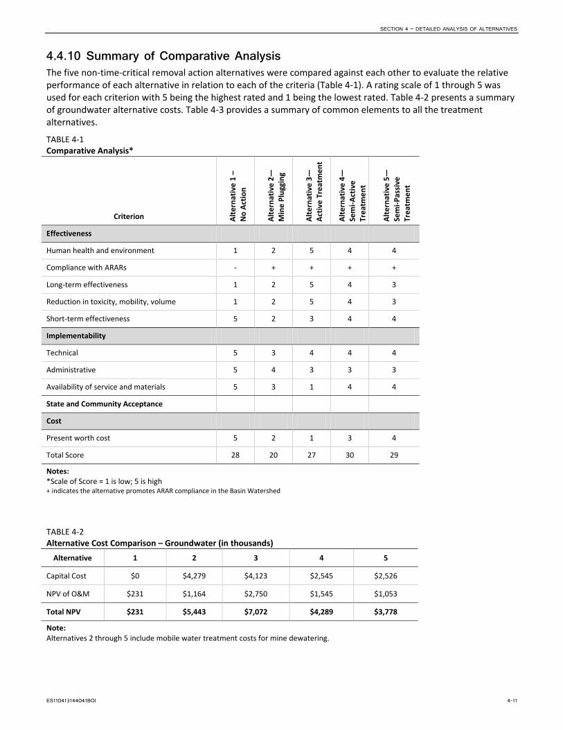
SECTION 4 – DETAILED ANALYSIS OF ALTERNATIVES
4.4.10 Summary of Comparative Analysis The five non-time-critical removal action alternatives were compared against each other to evaluate the relative performance of each alternative in relation to each of the criteria (Table 4-1). A rating scale of 1 through 5 was used for each criterion with 5 being the highest rated and 1 being the lowest rated. Table 4-2 presents a summary of groundwater alternative costs. Table 4-3 provides a summary of common elements to all the treatment alternatives.
TABLE 4-1 Comparative Analysis*
Criterion Alte
rnat
ive
1 –
N
o Ac
tion
Alte
rnat
ive
2—M
ine
Plug
ging
Alte
rnat
ive
3—Ac
tive
Trea
tmen
t
Alte
rnat
ive
4—Se
mi-A
ctiv
e Tr
eatm
ent
Alte
rnat
ive
5—
Sem
i-Pas
sive
Tr
eatm
ent
Effectiveness
Human health and environment 1 2 5 4 4
Compliance with ARARs - + + + +
Long-term effectiveness 1 2 5 4 3
Reduction in toxicity, mobility, volume 1 2 5 4 3
Short-term effectiveness 5 2 3 4 4
Implementability
Technical 5 3 4 4 4
Administrative 5 4 3 3 3
Availability of service and materials 5 3 1 4 4
State and Community Acceptance
Cost
Present worth cost 5 2 1 3 4
Total Score 28 20 27 30 29
Notes: *Scale of Score = 1 is low; 5 is high + indicates the alternative promotes ARAR compliance in the Basin Watershed
TABLE 4-2 Alternative Cost Comparison – Groundwater (in thousands)
Alternative 1 2 3 4 5
Capital Cost $0 $4,279 $4,123 $2,545 $2,526
NPV of O&M $231 $1,164 $2,750 $1,545 $1,053
Total NPV $231 $5,443 $7,072 $4,289 $3,778
Note: Alternatives 2 through 5 include mobile water treatment costs for mine dewatering.
ES110413144041BOI 4-11

SECTION 4 – DETAILED ANALYSIS OF ALTERNATIVES
TABLE 4-3 Cost of Common Elements (In addition to Remedial Treatment Alternatives)
Dewater Mine,
Treat/Discharge Adit Collection Basin AMD Channel Re-use Groundwater Cutoff
French Drain
Capital Cost $1,256,000 $97,000 $51,000 $31,000
In summary, Alternative 1 would not change existing conditions and would not offer protection of human health or the environment. The mine plugging and all three treatment alternatives would offer enhanced protection of human health and the environment through disruption of exposure pathways, or treatment of AMD discharge. No one alternative is completely protective of human health and the environment relative to the other alternatives. The criteria in Table 4-1 provide the most comprehensive evaluation of the alternatives to be considered in choosing a preferred alternative that will protect human health and the environment as an interim remedy.
4-12 ES110413144041BOI

5. References Atlantic Richfield Company. 2002. Milltown Reservoir Sediments NPL Site Clarkfork River Operable Unit, Public
Review Draft Feasibility Study Report. March.
Buchman, M.F. 2008. National Oceanic and Atmospheric Administration (NOAA) Screening Quick Reference Tables. NOAA OR&R. Report 08-1. Seattle, Washington, Office of Response and Restoration Division, 34 pp.
CDM Federal Programs Corporation. 2002. Draft Ecological Risk Evaluation, Basin Mining Area, Operable Unit 2, Jefferson County, Montana. November.
CDM Federal Programs Corporation. 2005a. Draft Feasibility Study Basin Mining Area Superfund Site, Operable Unit, Jefferson County, Montana. May.
CDM Federal Programs Corporation. 2005b. Remedial Investigation Report Addendum, Basin Mining Area Superfund Site, Operable Unit 2, Jefferson County, Montana. April 18.
CDM, See CDM Federal Programs Corporation.
CH2M HILL. 2011. Draft Focused Remedial Investigation, Bullion Mine, Operable Unit 6, Jefferson County, Montana. Prepared for U.S. Environmental Protection Agency, Region 8, Helena, Montana. July 2011 Draft.
CH2M HILL. 2013. Draft Focused Remedial Investigation, Bullion Mine, Operable Unit 6, Jefferson County, Montana. Prepared for U.S. Environmental Protection Agency, Region 8, Helena, Montana. April 2013 Draft.
DEQ. See Montana Department of Environmental Quality.
Michelsen. 2011. Development of Benthic SQCs for Freshwater Sediments in Washington, Oregon, and Idaho. Prepared for the Washington Department of Ecology. November.
Maxim Technologies, Inc. 2003. Final Construction Report – Bullion Mine and Millsite Removal Action, Jefferson County, Montana. Prepared for the USDA Forest Service Northern Region. USFS Contract No.: 53-0343-0-0014. November.
McDonald, D.D., C.G. Ingersoll, and T.A. Berger. 2000. Development and Evaluation of Consensus Based Sediment Quality Guidelines for Freshwater Ecosystems. Arch. Environ. Toxicol. 39, 20-31.
Montana Department of Environmental Quality. 2010. Montana Numeric Water Quality Standards. Circular DEQ-7. Planning, Prevention, and Assistance Division – Water Quality Standards Section. February.
Montana Department of Environmental Quality. 2012. Montana Numeric Water Quality Standards. Circular DEQ-7. Planning, Prevention, and Assistance Division – Water Quality Standards Section. October.
Montana State University. 2003. Reclaiming Hard Rock Mines: An in Depth Look at Vegetation, Soil, and Water on the Bullion Mine Site, Basin. LRES Capstone Course. Fall.
Montana State University. 2004. Hard Rock Mine Reclamation: Water, Soil, and Vegetation Issues, Bullion Mine. LRES Capstone Course. Fall.
MSU. See Montana State University.
SME. See Society for Mining, Metallurgy, and Exploration, Inc.
Society for Mining, Metallurgy, and Exploration, Inc. 1992. SME Mining Engineering Handbook. Hartman, Howard L. Senior Editor.
Tetra Tech Inc. 1996. Risk-Based Cleanup Guidelines for Abandoned Mine Sites. Prepared for Montana Department of Environmental Quality, Abandoned Mine Reclamation Bureau. December.
ES110413144041BOI 5-1

SECTION 5 – REFERENCES
U.S. Environmental Protection Agency. 1988. Guidance for Conducting Remedial Investigations and Feasibility Studies Under CERCLA. EPA 540/G-89/004. Office of Emergency and Remedial Response, U.S. Environmental Protection Agency. October.
U.S. Environmental Protection Agency. 1991. Human Health Evaluation Manual, Supplemental Guidance: Standard Default Exposure Factors. December.
U.S. Environmental Protection Agency. 1990. Promulgation of the National Oil and Hazardous Substances Pollution Contingency Plan. 55 FR 8666. March.
U.S. Environmental Protection Agency. 1998. Guidelines for Ecological Risk Assessment. U.S. Environmental Protection Agency. Washington, D.C. EPA/630/R-95/002F.
U.S. Environmental Protection Agency. 2000. “Clark Fork River Operable Unit River Reach-Specific Preliminary Remedial Action Objectives and Preliminary Remedial Goals.” Letter from Scott Brown EPA, to Barry Duff, Atlantic Richfield Company. April 25.
U.S. Environmental Protection Agency. 2009. National Recommended Water Quality Criteria. U.S. Environmental Protection Agency, Office of Water. EPA 822-R-02-047.
U.S. Environmental Protection Agency. 2010. Bullion Mine Site Statement of Work Regional Screening Levels (RSL) Summary Table. EPA Region 9. November.
USDA Natural Resources Conservation Service. 2009. Web Soil Survey 2.1, http://websoilsurvey.nrcs.usda.gov/app/HomePage.htm. Accessed March 27.
Weather Underground. 2009. http://www.wunderground.com/US/MT/Basin/KBTM.html#History. Accessed March 27.
5-2 ES110413144041BOI

Appendix A Applicable or Relevant
and Appropriate Requirements


Summary of Potential Federal and State Applicable or Relevant and Appropriate Requirements (ARARs)
Bullion Mine OU6 – Basin Mining Area NPL Site
I. INTRODUCTION
Section 121(d) of the Comprehensive Environmental Response, Compensation, and Liability Act (CERCLA), 42 U.S.C. ' 9621(d), the National Oil and Hazardous Substances Pollution Contingency Plan (NCP), 40 CFR Part 300 (1990), and guidance and policy issued by the U.S. Environmental Protection Agency (EPA) require that remedial actions under CERCLA comply with substantive provisions of applicable or relevant and appropriate standards, requirements, criteria, or limitations (ARARs) from State of Montana and federal environmental laws and state facility siting laws during and at the completion of the remedial action. These requirements are threshold standards that any selected remedy must meet, unless an ARAR waiver is granted.
This document identifies potential ARARs for possible remedial actions to be conducted at the former Bullion Mine Operable Unit 6 (OU6), of the Basin Mining Area National Priorities List Site. The following ARARs or groups of related ARARs are each identified by a statutory or regulatory citation, followed by a brief explanation of the ARAR and how and to what extent the ARAR is expected to apply to the activities to be conducted under this remedial action. EPA expects that there will be no physical remedial action except that institutional controls will be adopted. These will control any earth work on the site, building modifications, or possible removal of waste materials. Even though EPA may not implement a cleanup as part of this action, there may nevertheless be actions which need to be undertaken in compliance with certain ARARs. These ARARs are set forth below.
Substantive provisions of the requirements listed below are identified as ARARs pursuant to 40 Code of Federal Regulations (CFR) ' 300.400. ARARs must be attained during and at the completion of the remedial action.1 No Federal, State or local permit shall be required for the portion of any removal or remedial action conducted entirely on site in accordance with Section 121(e) of CERCLA.
II. TYPES OF ARARs
ARARs are either Aapplicable@ or Arelevant and appropriate.@ Both types of requirements are mandatory under CERCLA and the NCP.2 Applicable requirements are those cleanup standards, standards of control, and other substantive requirements, criteria or limitations promulgated under federal environmental or state environmental and facility siting laws that specifically address a hazardous substance, pollutant, contaminant, remedial action, location, or other circumstance found at a CERCLA site. Only those state standards that are identified by a
1 40 CFR § 300.435(b)(2); Preamble to the National Oil and Hazardous Substances Pollution Contingency Plan, 55 Federal Register (FR) 8755-8757 (March 8, 1990).
2 CERCLA ' 121(d)(2)(A), 42 U.S.C. ' 6921(d)(2)(A). See also, 40 CFR ' 300.430(f)(1)(i)(A).

state in a timely manner and that are more stringent than federal requirements may be applicable.3
Relevant and appropriate requirements are those cleanup standards, standards of control, and other substantive requirements, criteria or limitations promulgated under federal environmental or state environmental or facility siting laws that, while not Aapplicable@ to hazardous substances, pollutants, contaminants, remedial actions, locations, or other circumstances at a CERCLA site, address problems or situations sufficiently similar to those encountered at the CERCLA site that their use is well suited to the particular site. Only those state standards that are identified in a timely manner and are more stringent than federal requirements may be relevant and appropriate.4
The determination that a requirement is relevant and appropriate is a two-step process: (1) determination if a requirement is relevant and (2) determination if a requirement is appropriate. In general, this involves a comparison of a number of site-specific factors, including an examination of the purpose of the requirement and the purpose of the proposed CERCLA action; the medium and substances regulated by the requirement and the proposed action; the actions or activities regulated by the requirement and the remedial action; and the potential use of resources addressed in the requirement and the remedial action. When the analysis results in a determination that a requirement is both relevant and appropriate, such a requirement must be complied with to the same degree as if it were applicable.5
ARARs are contaminant, location, or action specific. Contaminant specific requirements address chemical or physical characteristics of compounds or substances on sites. These values establish acceptable amounts or concentrations of chemicals which may be found in or discharged to the ambient environment.
Location specific requirements are restrictions placed upon the concentrations of hazardous substances or the conduct of cleanup activities because they are in specific locations. Location specific ARARs relate to the geographical or physical positions of sites, rather than to the nature of contaminants at sites. Action specific requirements are usually technology based or activity based requirements or limitations on actions taken with respect to hazardous substances, pollutants or contaminants. A given cleanup activity will trigger an action specific requirement. Such requirements do not themselves determine the cleanup alternative, but define how chosen cleanup methods should be performed. At this time, EPA does not expect that there will be a physical cleanup at OU6 and therefore, there will be no action specific requirements for the OU6 remedial action. However, the institutional controls to be adopted as part of the action could trigger several of the ARARs listed below. If there is earthwork or excavation at OU6, if there are changes in structures of buildings, of if asbestos is discovered, several of the ARARs below could be triggered.
3 40 CFR ' 300.5.
4 40 CFR ' 300.5.
5 CERCLA Compliance with Other Laws Manual, Vol. I, OSWER Directive 9234.1-01, August 8, 1988, p. 1-11.

Many requirements listed as ARARs are promulgated as identical or near identical requirements in both federal and state law, usually pursuant to delegated environmental programs administered by EPA and the state. The Preamble to the NCP provides that such a situation results in citation to the state provision and treatment of the provision as a federal requirement.
Also contained in this list are policies, guidance or other sources of information which are Ato be considered@ in the implementation of the record of decision (ROD). Although not enforceable requirements, these documents are important sources of information which EPA and the State of Montana Department of Environmental Quality (MDEQ) may consider, especially in regard to the evaluation of public health and environmental risks; or which will be referred to, as appropriate, in developing cleanup actions.6 These final ARARs will be set forth as performance standards for any and all remedial design or remedial action work plans.
III. ARARS WAIVER
40 CFR § 300.430(f)(1)(ii)(C)(1) provides:
(C) An alternative that does not meet an ARAR under federal environmental or state environmental or facility siting laws may be selected under the following circumstances: (1) The alternative is an interim measure and will become part of a total remedial action that will attain the applicable or relevant and appropriate federal or state requirement;
***
The Bullion Mine OU6 cleanup will be an interim remedial action where compliance with groundwater and surface water ARARs is concerned. EPA doesn’t expect that this action will result in final compliance with surface and ground water ARARs at the Basin Mine Area NPL Site. Final compliance with these water ARARs may happen after all 5 OUs at the Site have been addressed. If not, EPA will issue a technical impracticability waiver at the time it issues the ROD for the last of the five OUs at the Site. This will be as provided in 40 CFR § 300.430(f)(1)(ii)(C)(3). Any waiver will explain why it is technically impracticable to meet certain water quality ARARs at that time. For now, EPA is invoking the interim action waiver as provided in 40 CFR § 300.430(f)(1)(ii)(C)(1) with respect to all water quality ARARs at OU6. It should be noted that EPA expects all other ARARs for the Bullion Mine OU6 action to be complied with during or at completion of the action, as appropriate.
6 40 CFR § 300.400(g)(3); Preamble to the NCP, 55 Fed. Reg. 8744-8746 (March 8, 1990).

APPENDIX SUMMARY OF FEDERAL AND STATE APLICABLE OR RELEVANT AND APPROPRIATE REQUIREMENTS (ARARS) AND TO BE CONSIDERED INFORMATION (TBCS), BULLION MINE SITE (OU6)
B-4
APPENDIX Summary of Federal and State Applicable or Relevant and Appropriate Requirements (ARARs) and To Be Considered Information (TBCs) Bullion Mine Site (OU6)
Statutes, Regulations, Standards, or Requirements
Citations or References
ARAR Determination Description Comment
Chemical‐Specific
Location‐Specific
Action‐Specific
Federal ARARs and TBCs
National Historic Preservation Act (NHPA) National Register of Historic Places Determinations of eligibility for inclusion in the National Register of Historic Places Protection of historic properties Requirements for environmental information documents and third‐party agreements for EPA actions subject to NEPA Historic Sites Act of 1935
16 United States Code (U.S.C.). 470 36 Code of Federal Regulations (CFR) 60 36 CFR 63 16 U.S.C. 461, et seq.
Applicable This statute and implementing regulations require federal agencies to take into account the effect of this response action upon any district, site, building, structure, or object that is included in or eligible for the National Register of Historic Places (generally, 50 years old or older).
It is not anticipated that proposed areas for remedial action at the Bullion Mine Site are eligible for the National Register of Historic Places. If cultural resources on, or eligible for, the national register are identified, it will be necessary to determine if there will be an adverse effect and, if so, how the effect may be minimized or mitigated, in consultation with the appropriate State Historic Preservation Office (SHPO). [A cultural resource inventory of the site was prepared and submitted to the Montana SHPO. Findings indicated that the site did not qualify for the National Register of Historic Places.]
Archaeological and Historic Preservation Act Requirements for environmental information documents and third‐party agreements for EPA actions subject to NEPA Protection of archaeological
16 U.S.C. 469 43 CFR 7
Applicable
This statute and implementing regulations establish requirements for the evaluation and preservation of historical and archaeological data, which may be destroyed through alteration of terrain as a result of a federal construction project or a federally licensed activity or program.
The unauthorized removal of archaeological resources from public or Indian lands is prohibited without a permit and any archaeological investigations at a site must be conducted by a professional archaeologist.
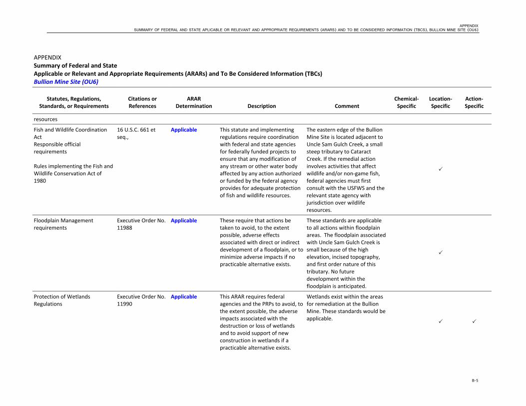
APPENDIX SUMMARY OF FEDERAL AND STATE APLICABLE OR RELEVANT AND APPROPRIATE REQUIREMENTS (ARARS) AND TO BE CONSIDERED INFORMATION (TBCS), BULLION MINE SITE (OU6)
B-5
APPENDIX Summary of Federal and State Applicable or Relevant and Appropriate Requirements (ARARs) and To Be Considered Information (TBCs) Bullion Mine Site (OU6)
Statutes, Regulations, Standards, or Requirements
Citations or References
ARAR Determination Description Comment
Chemical‐Specific
Location‐Specific
Action‐Specific
resources
Fish and Wildlife Coordination Act Responsible official requirements Rules implementing the Fish and Wildlife Conservation Act of 1980
16 U.S.C. 661 et seq.,
Applicable This statute and implementing regulations require coordination with federal and state agencies for federally funded projects to ensure that any modification of any stream or other water body affected by any action authorized or funded by the federal agency provides for adequate protection of fish and wildlife resources.
The eastern edge of the Bullion Mine Site is located adjacent to Uncle Sam Gulch Creek, a small steep tributary to Cataract Creek. If the remedial action involves activities that affect wildlife and/or non‐game fish, federal agencies must first consult with the USFWS and the relevant state agency with jurisdiction over wildlife resources.
Floodplain Management requirements
Executive Order No. 11988
Applicable These require that actions be taken to avoid, to the extent possible, adverse effects associated with direct or indirect development of a floodplain, or to minimize adverse impacts if no practicable alternative exists.
These standards are applicable to all actions within floodplain areas. The floodplain associated with Uncle Sam Gulch Creek is small because of the high elevation, incised topography, and first order nature of this tributary. No future development within the floodplain is anticipated.
Protection of Wetlands Regulations
Executive Order No. 11990
Applicable This ARAR requires federal agencies and the PRPs to avoid, to the extent possible, the adverse impacts associated with the destruction or loss of wetlands and to avoid support of new construction in wetlands if a practicable alternative exists.
Wetlands exist within the areas for remediation at the Bullion Mine. These standards would be applicable.

APPENDIX SUMMARY OF FEDERAL AND STATE APLICABLE OR RELEVANT AND APPROPRIATE REQUIREMENTS (ARARS) AND TO BE CONSIDERED INFORMATION (TBCS), BULLION MINE SITE (OU6)
B-6
APPENDIX Summary of Federal and State Applicable or Relevant and Appropriate Requirements (ARARs) and To Be Considered Information (TBCs) Bullion Mine Site (OU6)
Statutes, Regulations, Standards, or Requirements
Citations or References
ARAR Determination Description Comment
Chemical‐Specific
Location‐Specific
Action‐Specific
Endangered Species Act (ESA)
16 U.S.C. 1531
Applicable This statute and implementing regulations provide that federal activities not jeopardize the continued existence of any threatened or endangered species. ESA Section 7 requires consultation with the United States Fish and Wildlife Service (USFWS) to identify the possible presence of protected species and mitigate potential impacts on such species.
If threatened or endangered species are identified within the areas identified for remediation, activities must be designed to conserve the species and their habitat.
Migratory Bird Treaty Act List of Migratory Birds
16 U.S.C. 703, et seq. 50 CFR 10.13
Relevant and Appropriate
Makes it unlawful to “hunt, take, capture, kill,” or take various other actions adversely affecting a broad range of migratory birds, without the prior approval of the Department of the Interior.
The selected remedial actions will be carried out in a manner to avoid adversely affecting migratory bird species, including individual birds or their nests.
Bald Eagle Protection Act 16 U.S.C. 668, et seq.
Applicable This requirement establishes a federal responsibility for protection of bald and golden eagles, and requires continued consultation with the U.S. Fish and Wildlife Service during remedial design and remedial construction to ensure that any cleanup of the site does not unnecessarily adversely affect the bald and golden eagles.
If bald or golden eagles are identified within the areas identified for remediation, activities must be designed to conserve the species and their habitat.

APPENDIX SUMMARY OF FEDERAL AND STATE APLICABLE OR RELEVANT AND APPROPRIATE REQUIREMENTS (ARARS) AND TO BE CONSIDERED INFORMATION (TBCS), BULLION MINE SITE (OU6)
B-7
APPENDIX Summary of Federal and State Applicable or Relevant and Appropriate Requirements (ARARs) and To Be Considered Information (TBCs) Bullion Mine Site (OU6)
Statutes, Regulations, Standards, or Requirements
Citations or References
ARAR Determination Description Comment
Chemical‐Specific
Location‐Specific
Action‐Specific
Native American Graves Protection and Repatriation Act
25 U.S.C. 3001, et seq.
Applicable The Act prioritizes ownership or control over Native American cultural items, including human remains, funerary objects and sacred objects, excavated or discovered on federal or tribal lands. Federal agencies and museums that have possession or control over Native American human remains and associated funerary objects are required under the Act to compile an inventory of such items and, to the extent possible, identify their geographical and cultural affiliation. Once the cultural affiliation of such objects is established, the federal agency or museum must expeditiously return such items, upon request by a lineal descendent of the individual Native American or tribe identified.
No known cultural items, including human remains, funerary objects and sacred objects are located on the site. If such items are discovered during excavation activities then the provisions of this regulation will be applicable.
American Indian Religious Freedom Act
42 U.S.C. 1996 et seq.
Applicable This Act establishes a federal responsibility to protect and preserve the inherent right of American Indians to believe, express and exercise the traditional religions of American Indians. This right includes, but is not limited to, access to sites, use and possession of sacred objects,
The Act requires Federal agencies to protect Indian religious freedom by refraining from interfering with access, possession and use of religious objects, and by consulting with Indian organizations regarding proposed actions affecting their religious freedom.
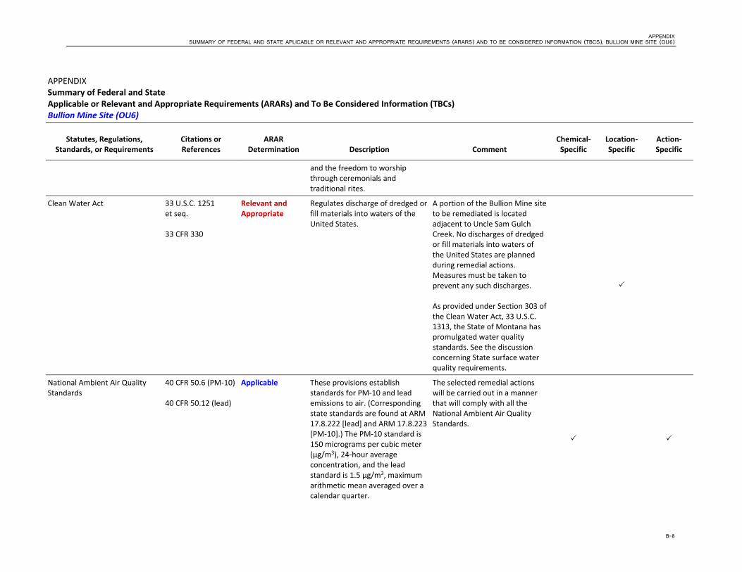
APPENDIX SUMMARY OF FEDERAL AND STATE APLICABLE OR RELEVANT AND APPROPRIATE REQUIREMENTS (ARARS) AND TO BE CONSIDERED INFORMATION (TBCS), BULLION MINE SITE (OU6)
B-8
APPENDIX Summary of Federal and State Applicable or Relevant and Appropriate Requirements (ARARs) and To Be Considered Information (TBCs) Bullion Mine Site (OU6)
Statutes, Regulations, Standards, or Requirements
Citations or References
ARAR Determination Description Comment
Chemical‐Specific
Location‐Specific
Action‐Specific
and the freedom to worship through ceremonials and traditional rites.
Clean Water Act 33 U.S.C. 1251 et seq. 33 CFR 330
Relevant and Appropriate
Regulates discharge of dredged or fill materials into waters of the United States.
A portion of the Bullion Mine site to be remediated is located adjacent to Uncle Sam Gulch Creek. No discharges of dredged or fill materials into waters of the United States are planned during remedial actions. Measures must be taken to prevent any such discharges. As provided under Section 303 of the Clean Water Act, 33 U.S.C. 1313, the State of Montana has promulgated water quality standards. See the discussion concerning State surface water quality requirements.
National Ambient Air Quality Standards
40 CFR 50.6 (PM‐10) 40 CFR 50.12 (lead)
Applicable These provisions establish standards for PM‐10 and lead emissions to air. (Corresponding state standards are found at ARM 17.8.222 [lead] and ARM 17.8.223 [PM‐10].) The PM‐10 standard is 150 micrograms per cubic meter (μg/m3), 24‐hour average concentration, and the lead standard is 1.5 μg/m3, maximum arithmetic mean averaged over a calendar quarter.
The selected remedial actions will be carried out in a manner that will comply with all the National Ambient Air Quality Standards.

APPENDIX SUMMARY OF FEDERAL AND STATE APLICABLE OR RELEVANT AND APPROPRIATE REQUIREMENTS (ARARS) AND TO BE CONSIDERED INFORMATION (TBCS), BULLION MINE SITE (OU6)
B-9
APPENDIX Summary of Federal and State Applicable or Relevant and Appropriate Requirements (ARARs) and To Be Considered Information (TBCs) Bullion Mine Site (OU6)
Statutes, Regulations, Standards, or Requirements
Citations or References
ARAR Determination Description Comment
Chemical‐Specific
Location‐Specific
Action‐Specific
Protection and Enhancement of the Cultural Environment
16 U.S.C. 470 Executive Order No. 11593
Applicable Directs federal agencies to institute procedures to ensure programs contribute to the preservation and enhancement of non‐federally owned historic resources.
Consultation with the Advisory Council on Historic Preservation is required if remedial activities should threaten cultural resources.
The Archaeological Resources Protection Act of 1979
16 U.S.C. 470aa‐47011
Relevant and Appropriate
Requires a permit for any excavation or removal of archeological resources from public lands or Indian lands.
Substantive portions of this act may be relevant and appropriate if archeological resources are encountered during onsite remedial action activity involving public lands or Indian lands.
Federal and State RCRA Subtitle D and Solid Waste Management Requirements
40 CFR 257 Applicable Establishes criteria under Subtitle D of the Resource Conservation and Recovery Act for use in determining which solid waste disposal facilities and practices pose a reasonable probability of adverse effects on health or the environment.
Solid waste requirements are listed herein because contaminated soil to be addressed in the remedial action is considered solid waste.
Federal RCRA Subtitle C Requirements
42 U.S.C. Section 9621, et seq. 40 CFR 261‐268
Relevant and Appropriate
RCRA Subtitle C and implementing regulations are designated as applicable for any hazardous wastes that are actively “generated” or that were “placed” or “disposed” after 1980.
RCRA Subtitle C requirements will generally not be relevant and appropriate for those wastes for which EPA has specifically determined that Subtitle C regulation is not warranted (i.e., wastes covered by the Bevill exclusion). Thus mining contaminated soil is assumed to not be classified as hazardous

APPENDIX SUMMARY OF FEDERAL AND STATE APLICABLE OR RELEVANT AND APPROPRIATE REQUIREMENTS (ARARS) AND TO BE CONSIDERED INFORMATION (TBCS), BULLION MINE SITE (OU6)
B-10
APPENDIX Summary of Federal and State Applicable or Relevant and Appropriate Requirements (ARARs) and To Be Considered Information (TBCs) Bullion Mine Site (OU6)
Statutes, Regulations, Standards, or Requirements
Citations or References
ARAR Determination Description Comment
Chemical‐Specific
Location‐Specific
Action‐Specific
waste. However these regulations may be relevant and appropriate to any unknown, potentially hazardous wastes encountered during excavation of contaminated soils (e.g. buried drums, etc.).
Occupational Safety and Health Act
29 CFR 1910 To Be Considered Provides standards and guidance for worker protection during conduct of construction activities.
OSHA regulations are construction standards and not environmental standards. These regulations are requirements for remedial activities as provided by law.
Federal Aviation Administration (FAA) Regulations
14 CFR 77.13, et seq. 14 CFR 139.341 14 CFR 157
To Be Considered Describes the standards used for determining obstructions to air navigation, navigational aids, or navigational facilities. Provides procedures for identifying, marking, and lighting construction and other unserviceable areas. Includes procedures for providing notice of construction, alteration, activation, and deactivation of airports.
FAA regulations are construction standards and not environmental standards. No permit is required for response actions conducted entirely on‐site.

APPENDIX SUMMARY OF FEDERAL AND STATE APLICABLE OR RELEVANT AND APPROPRIATE REQUIREMENTS (ARARS) AND TO BE CONSIDERED INFORMATION (TBCS), BULLION MINE SITE (OU6)
B-11
APPENDIX Summary of Federal and State Applicable or Relevant and Appropriate Requirements (ARARs) and To Be Considered Information (TBCs) Bullion Mine Site (OU6)
Statutes, Regulations, Standards, or Requirements
Citations or References
ARAR Determination Description Comment
Chemical‐Specific
Location‐Specific
Action‐Specific
FEMA Flood Insurance Rate Map Map ID 3001280005A, (01/05/2001)
To Be Considered The FEMA flood insurance rate map (FIRM) indicates the special flood hazard area delineated by Zone A and areas outside delineated by Zone X.
This map contains TBC information to be used when remediating property within floodplain areas. However it is unlikely that FEMA has mapped the flood plain with in Uncle Sam Gulch, because of its remote location and lack of development beyond a mine property.
State of Montana ARARs and TBCs
Groundwater Protection Administrative Rules of Montana (ARM) 17.30.1005 ARM 17.30.1006 ARM 17.30.1011
Applicable but Waived3
Explains the applicability and basis for the groundwater standards in ARM 17.30.1006, which establish the maximum allowable changes in groundwater quality and may limit discharges to groundwater. Provides that groundwater is classified I through IV based on its present and future most beneficial uses and also sets the standards for the different classes of groundwater listed in department Circular WQB‐7.1 This section provides that any groundwater whose existing quality is higher than the standard for its classification
The OU addressed in this feasibility study does address contaminated groundwater. Measures will be taken to prevent contamination of groundwater.

APPENDIX SUMMARY OF FEDERAL AND STATE APLICABLE OR RELEVANT AND APPROPRIATE REQUIREMENTS (ARARS) AND TO BE CONSIDERED INFORMATION (TBCS), BULLION MINE SITE (OU6)
B-12
APPENDIX Summary of Federal and State Applicable or Relevant and Appropriate Requirements (ARARs) and To Be Considered Information (TBCs) Bullion Mine Site (OU6)
Statutes, Regulations, Standards, or Requirements
Citations or References
ARAR Determination Description Comment
Chemical‐Specific
Location‐Specific
Action‐Specific
must be maintained at that high quality in accordance with MCA 75‐5‐303 and ARM 17.30.7.
Montana Water Quality Act and Regulations
Montana Code Annotated (MCA) 75‐5‐101, et seq. ARM 17.30.607
Applicable but Waived3
The Montana Water Quality Act establishes requirements for restoring and maintaining the quality of surface and groundwater. Montana's regulations classify State waters according to quality, place restrictions on the discharge of pollutants to State waters, and prohibit degradation of State waters. Tributaries to the Boulder River have been classified B‐1. Basin Creek and Cataract Creek and their tributaries are part of the Boulder River drainage.
The OU addressed in this feasibility study does address contaminated groundwater and surface water. Due to the proximity of remedial actions to surface waters, measures will be taken to prevent contamination of surface waters.
Montana Water Quality Act and Regulations (Continued)
ARM 17.30.623
Waters classified B‐1 are, after conventional treatment for removal of naturally present impurities, suitable for drinking, culinary and food processing purposes. These waters are also suitable for bathing, swimming and recreation, growth and propagation of salmonid fishes and associated aquatic life, waterfowl and furbearers, and use for agricultural and industrial
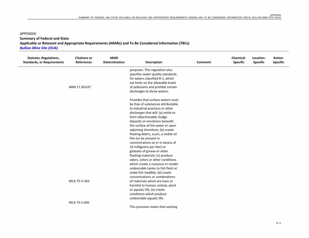
APPENDIX SUMMARY OF FEDERAL AND STATE APLICABLE OR RELEVANT AND APPROPRIATE REQUIREMENTS (ARARS) AND TO BE CONSIDERED INFORMATION (TBCS), BULLION MINE SITE (OU6)
B-13
APPENDIX Summary of Federal and State Applicable or Relevant and Appropriate Requirements (ARARs) and To Be Considered Information (TBCs) Bullion Mine Site (OU6)
Statutes, Regulations, Standards, or Requirements
Citations or References
ARAR Determination Description Comment
Chemical‐Specific
Location‐Specific
Action‐Specific
ARM 17.30.637 MCA 75‐5‐303 MCA 75‐5‐605
purposes. This regulation also specifies water quality standards for waters classified B‐1, which set limits on the allowable levels of pollutants and prohibit certain discharges to those waters. Provides that surface waters must be free of substances attributable to industrial practices or other discharges that will: (a) settle to form objectionable sludge deposits or emulsions beneath the surface of the water or upon adjoining shorelines; (b) create floating debris, scum, a visible oil film (or be present in concentrations at or in excess of 10 milligrams per liter) or globules of grease or other floating materials; (c) produce odors, colors or other conditions which create a nuisance or render undesirable tastes to fish flesh or make fish inedible; (d) create concentrations or combinations of materials which are toxic or harmful to human, animal, plant or aquatic life; (e) create conditions which produce undesirable aquatic life. This provision states that existing

APPENDIX SUMMARY OF FEDERAL AND STATE APLICABLE OR RELEVANT AND APPROPRIATE REQUIREMENTS (ARARS) AND TO BE CONSIDERED INFORMATION (TBCS), BULLION MINE SITE (OU6)
B-14
APPENDIX Summary of Federal and State Applicable or Relevant and Appropriate Requirements (ARARs) and To Be Considered Information (TBCs) Bullion Mine Site (OU6)
Statutes, Regulations, Standards, or Requirements
Citations or References
ARAR Determination Description Comment
Chemical‐Specific
Location‐Specific
Action‐Specific
ARM 17.30.705
uses of state waters and the level of water quality necessary to protect the uses must be maintained and protected. This section of the Montana Water Quality Act prohibits the causing of pollution of any state waters. Pollution is defined as contamination or other alteration of physical, chemical, or biological properties of state waters which exceeds that permitted by the water quality standards. Also, it is unlawful to place or cause to be placed any wastes where they will cause pollution of any state waters Existing and anticipated uses of surface water and water quality necessary to support those uses must be maintained and protected unless degradation is allowed under the nondegradation rules at ARM 17.30.708.
Substantive MPDES Permit Requirements
ARM 17.30.1342‐1344
Applicable These set forth the substantive requirements applicable to all MPDES and National Pollutant Discharge Elimination System
Treated discharge into waters of the State of Montana (Uncle Sam Gulch Creek) is planned as part of the final remedial

APPENDIX SUMMARY OF FEDERAL AND STATE APLICABLE OR RELEVANT AND APPROPRIATE REQUIREMENTS (ARARS) AND TO BE CONSIDERED INFORMATION (TBCS), BULLION MINE SITE (OU6)
B-15
APPENDIX Summary of Federal and State Applicable or Relevant and Appropriate Requirements (ARARs) and To Be Considered Information (TBCs) Bullion Mine Site (OU6)
Statutes, Regulations, Standards, or Requirements
Citations or References
ARAR Determination Description Comment
Chemical‐Specific
Location‐Specific
Action‐Specific
(NPDES) permits. action. This discharge will be made in consultation with the State of Montana. Measures must be taken to prevent any uncontrolled discharges.2
Stormwater Runoff Control Requirements
ARM 17.24.633 ARM 17.30.1341
Applicable All surface drainage from a disturbed area must be treated by the best technology currently available. DEQ has issued general storm water permits for certain activities. The substantive requirements of the permits are applicable for the following activities: for construction activities B General Permit for Storm Water Discharge Associated with Construction Activity, Permit No. MTR100000 (April 16, 2007).
These requirements would be applicable to disturbed remedial areas. Generally, the permits require best management practices (BMP) and all reasonable steps to minimize or prevent any discharge which has a reasonable likelihood of adversely affecting human health or the environment.
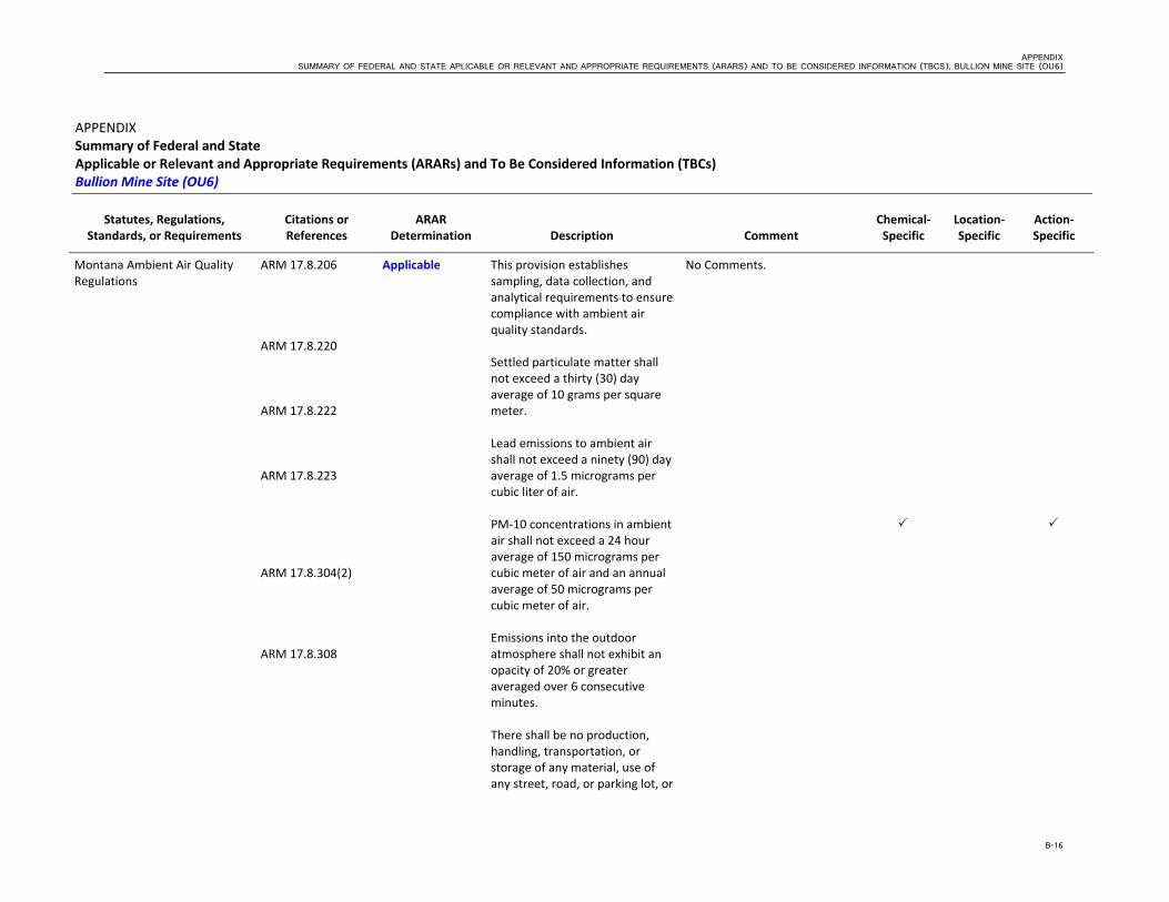
APPENDIX SUMMARY OF FEDERAL AND STATE APLICABLE OR RELEVANT AND APPROPRIATE REQUIREMENTS (ARARS) AND TO BE CONSIDERED INFORMATION (TBCS), BULLION MINE SITE (OU6)
B-16
APPENDIX Summary of Federal and State Applicable or Relevant and Appropriate Requirements (ARARs) and To Be Considered Information (TBCs) Bullion Mine Site (OU6)
Statutes, Regulations, Standards, or Requirements
Citations or References
ARAR Determination Description Comment
Chemical‐Specific
Location‐Specific
Action‐Specific
Montana Ambient Air Quality Regulations
ARM 17.8.206 ARM 17.8.220 ARM 17.8.222 ARM 17.8.223 ARM 17.8.304(2) ARM 17.8.308
Applicable
This provision establishes sampling, data collection, and analytical requirements to ensure compliance with ambient air quality standards. Settled particulate matter shall not exceed a thirty (30) day average of 10 grams per square meter. Lead emissions to ambient air shall not exceed a ninety (90) day average of 1.5 micrograms per cubic liter of air. PM‐10 concentrations in ambient air shall not exceed a 24 hour average of 150 micrograms per cubic meter of air and an annual average of 50 micrograms per cubic meter of air. Emissions into the outdoor atmosphere shall not exhibit an opacity of 20% or greater averaged over 6 consecutive minutes. There shall be no production, handling, transportation, or storage of any material, use of any street, road, or parking lot, or
No Comments.

APPENDIX SUMMARY OF FEDERAL AND STATE APLICABLE OR RELEVANT AND APPROPRIATE REQUIREMENTS (ARARS) AND TO BE CONSIDERED INFORMATION (TBCS), BULLION MINE SITE (OU6)
B-17
APPENDIX Summary of Federal and State Applicable or Relevant and Appropriate Requirements (ARARs) and To Be Considered Information (TBCs) Bullion Mine Site (OU6)
Statutes, Regulations, Standards, or Requirements
Citations or References
ARAR Determination Description Comment
Chemical‐Specific
Location‐Specific
Action‐Specific
ARM 17.8.604(2)
operation of a construction site or demolition project unless reasonable precautions are taken to control emissions of airborne particles. The 20% opacity limit described above is also specified for these activities. Lists material that may not be disposed of by open burning except as approved by the department.
Open burning may be applicable if actions addressed clearing and grubbing debris through open burning.
Montana Mine Reclamation Regulations
ARM 17.24.761 Relevant and Appropriate
Specifies measures for controlling fugitive dust emissions during reclamation activities, such as watering, chemically stabilizing, or frequently compacting and scraping roads, promptly removing rock, soil or other dust‐forming debris from roads, restricting vehicle speeds, and promptly revegetating regraded lands.
Some measures identified in this regulation could be considered relevant and appropriate to control fugitive dust emissions in connection with excavation, earth moving and transportation activities conducted as part of the remedy at the site.
Montana Antiquities Act MCA 22‐3‐421, et seq
Relevant and Appropriate
Addresses the responsibilities of State agencies regarding historic and prehistoric sites including buildings, structures, paleontological sites, archaeological sites on state owned lands. This act requires avoidance or mitigation of impacts to heritage property or
If historic or prehistoric sites are discovered during excavation activities on any state‐owned lands then the provisions of this regulation may apply. These regulations may be relevant and appropriate for lands with other types of ownership.
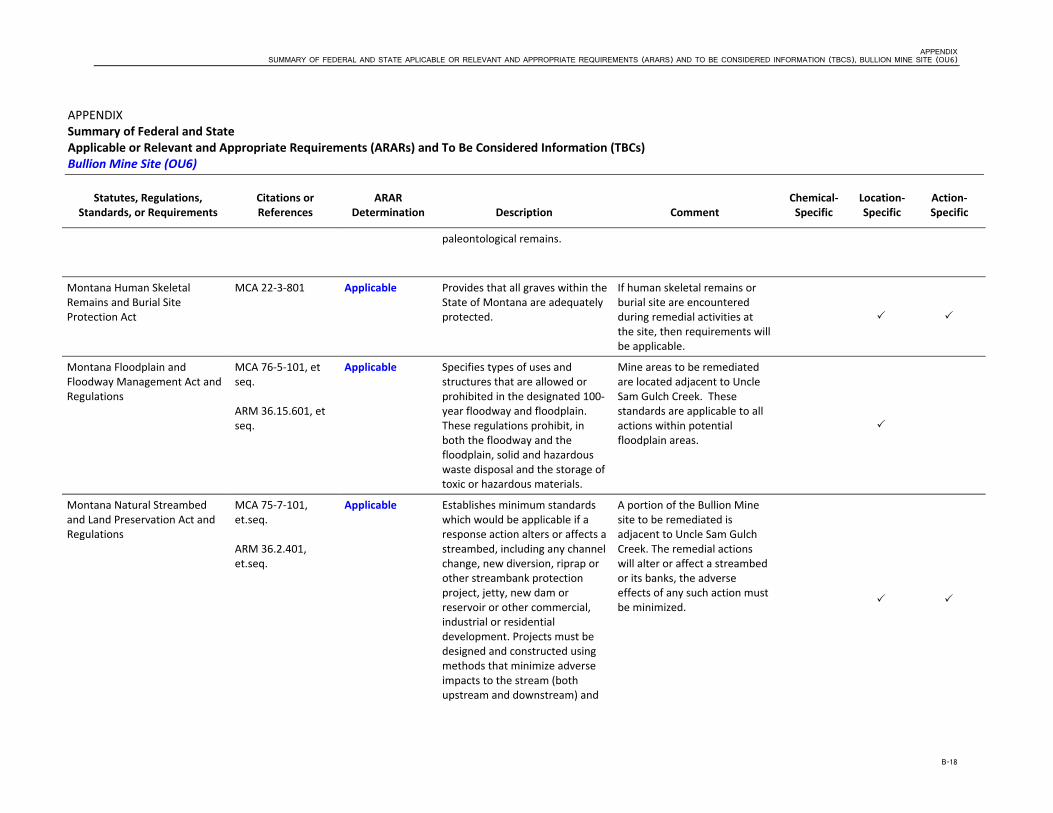
APPENDIX SUMMARY OF FEDERAL AND STATE APLICABLE OR RELEVANT AND APPROPRIATE REQUIREMENTS (ARARS) AND TO BE CONSIDERED INFORMATION (TBCS), BULLION MINE SITE (OU6)
B-18
APPENDIX Summary of Federal and State Applicable or Relevant and Appropriate Requirements (ARARs) and To Be Considered Information (TBCs) Bullion Mine Site (OU6)
Statutes, Regulations, Standards, or Requirements
Citations or References
ARAR Determination Description Comment
Chemical‐Specific
Location‐Specific
Action‐Specific
paleontological remains.
Montana Human Skeletal Remains and Burial Site Protection Act
MCA 22‐3‐801 Applicable Provides that all graves within the State of Montana are adequately protected.
If human skeletal remains or burial site are encountered during remedial activities at the site, then requirements will be applicable.
Montana Floodplain and Floodway Management Act and Regulations
MCA 76‐5‐101, et seq. ARM 36.15.601, et seq.
Applicable Specifies types of uses and structures that are allowed or prohibited in the designated 100‐year floodway and floodplain. These regulations prohibit, in both the floodway and the floodplain, solid and hazardous waste disposal and the storage of toxic or hazardous materials.
Mine areas to be remediated are located adjacent to Uncle Sam Gulch Creek. These standards are applicable to all actions within potential floodplain areas.
Montana Natural Streambed and Land Preservation Act and Regulations
MCA 75‐7‐101, et.seq. ARM 36.2.401, et.seq.
Applicable
Establishes minimum standards which would be applicable if a response action alters or affects a streambed, including any channel change, new diversion, riprap or other streambank protection project, jetty, new dam or reservoir or other commercial, industrial or residential development. Projects must be designed and constructed using methods that minimize adverse impacts to the stream (both upstream and downstream) and
A portion of the Bullion Mine site to be remediated is adjacent to Uncle Sam Gulch Creek. The remedial actions will alter or affect a streambed or its banks, the adverse effects of any such action must be minimized.

APPENDIX SUMMARY OF FEDERAL AND STATE APLICABLE OR RELEVANT AND APPROPRIATE REQUIREMENTS (ARARS) AND TO BE CONSIDERED INFORMATION (TBCS), BULLION MINE SITE (OU6)
B-19
APPENDIX Summary of Federal and State Applicable or Relevant and Appropriate Requirements (ARARs) and To Be Considered Information (TBCs) Bullion Mine Site (OU6)
Statutes, Regulations, Standards, or Requirements
Citations or References
ARAR Determination Description Comment
Chemical‐Specific
Location‐Specific
Action‐Specific
future disturbances to the stream.
Montana Natural Streambed and Land Preservation Act and Regulations (continued)
MCA 87‐5‐502 and 504
Applicable
Provides that a state agency or subdivision shall not construct, modify, operate, maintain or fail to maintain any construction project or hydraulic project which may or will obstruct, damage, diminish, destroy, change, modify, or vary the natural existing shape and form of any stream or its banks or tributaries in a manner that will adversely affect any fish or game habitat.
Montana Solid Waste Requirements
MCA 75‐10‐212
Applicable Prohibits dumping or leaving any debris or refuse upon or within 200 yards of any highway, road, street, or alley of the State or other public property, or on privately owned property where
The listed requirements apply to the offsite transportation of solid wastes to disposal facilities, should that remedial option be chosen.

APPENDIX SUMMARY OF FEDERAL AND STATE APLICABLE OR RELEVANT AND APPROPRIATE REQUIREMENTS (ARARS) AND TO BE CONSIDERED INFORMATION (TBCS), BULLION MINE SITE (OU6)
B-20
APPENDIX Summary of Federal and State Applicable or Relevant and Appropriate Requirements (ARARs) and To Be Considered Information (TBCs) Bullion Mine Site (OU6)
Statutes, Regulations, Standards, or Requirements
Citations or References
ARAR Determination Description Comment
Chemical‐Specific
Location‐Specific
Action‐Specific
ARM 17.50.523 ARM 17.50.1009(1)(c) ARM 17.50.1204 ARM 17.50.1109
hunting, fishing, or other recreation is permitted. Specifies that solid waste must be transported in such a manner as to prevent its discharge, dumping, spilling or leaking from the transport vehicle. Requires that solid waste facilities not discharge pollutants in excess of state standards. A solid waste facility must contain a leachate collection system unless there is no potential for migration of a constituent in Appendix I or II to 40 CFR 258. Solid waste facilities must either be designed to ensure that MCLs are not exceeded or the solid waste facility must contain a composite liner and leachate collection system that complies with specified criteria. Requires a run‐on control system to prevent flow onto the active portion of the solid waste facility during the peak discharge from a 25‐year storm and a run‐off control system from the active
While a repository for placement of the wastes from this OU may be obtained and developed as part of other response actions for this site, the placement of the wastes from the remedial actions must be consistent with these applicable requirements.

APPENDIX SUMMARY OF FEDERAL AND STATE APLICABLE OR RELEVANT AND APPROPRIATE REQUIREMENTS (ARARS) AND TO BE CONSIDERED INFORMATION (TBCS), BULLION MINE SITE (OU6)
B-21
APPENDIX Summary of Federal and State Applicable or Relevant and Appropriate Requirements (ARARs) and To Be Considered Information (TBCs) Bullion Mine Site (OU6)
Statutes, Regulations, Standards, or Requirements
Citations or References
ARAR Determination Description Comment
Chemical‐Specific
Location‐Specific
Action‐Specific
ARM 17.50.1403 ARM 17.50.1404
portion of the solid waste facility to collect and control at least the water volume resulting from a 24‐hour, 25‐year storm. Sets forth closure requirements for solid waste facilities. Solid waste facilities must meet the following criteria: (1) install a final cover that is designed to minimize infiltration and erosion; (2) design and construct the final cover system to minimize infiltration through the closed unit by the use of an infiltration layer that contains a minimum 18 inches of earthen material and has a permeability less than or equal to the permeability of any bottom liner, barrier layer, or natural subsoils or a permeability no greater than 1 X 10‐5 cm/sec, whichever is less; and (3) minimize erosion of the final cover by the use of a seed bed layer that contains a minimum of six inches of earthen material that is capable of sustaining native plant growth. Post closure care requires maintenance of the integrity and effectiveness of any final cover,

APPENDIX SUMMARY OF FEDERAL AND STATE APLICABLE OR RELEVANT AND APPROPRIATE REQUIREMENTS (ARARS) AND TO BE CONSIDERED INFORMATION (TBCS), BULLION MINE SITE (OU6)
B-22
APPENDIX Summary of Federal and State Applicable or Relevant and Appropriate Requirements (ARARs) and To Be Considered Information (TBCs) Bullion Mine Site (OU6)
Statutes, Regulations, Standards, or Requirements
Citations or References
ARAR Determination Description Comment
Chemical‐Specific
Location‐Specific
Action‐Specific
MCA 75‐10‐206
including making repairs to the cover as necessary to correct the effects of settlement, subsidence, erosion, or other events, and preventing run‐on and run‐off from eroding or otherwise damaging the cover and compliance with the groundwater monitoring requirements found at ARM Title 17, chapter 50, subchapter 13. Allows variances to be granted from solid waste regulations if failure to comply with the rules does not result in a danger to public health or safety or compliance with specific rules would produce hardship without producing benefits to the health and safety of the public that outweigh the hardship.

APPENDIX SUMMARY OF FEDERAL AND STATE APLICABLE OR RELEVANT AND APPROPRIATE REQUIREMENTS (ARARS) AND TO BE CONSIDERED INFORMATION (TBCS), BULLION MINE SITE (OU6)
B-23
APPENDIX Summary of Federal and State Applicable or Relevant and Appropriate Requirements (ARARs) and To Be Considered Information (TBCs) Bullion Mine Site (OU6)
Statutes, Regulations, Standards, or Requirements
Citations or References
ARAR Determination Description Comment
Chemical‐Specific
Location‐Specific
Action‐Specific
Noxious Weeds MCA 7‐22‐2101 (8)(a) ARM 4.5.201, et seq.
Applicable Defines "noxious weeds" as any exotic plant species established or that may be introduced in the state which may render land unfit for agriculture, forestry, livestock, wildlife, or other beneficial uses or that may harm native plant communities and that is designated: (I) as a statewide noxious weed by rule of the department; or (ii) as a district noxious weed by a board, following public notice of intent and a public hearing.
Applicable requirements for the alternatives which include establishment of seed during restoration.
Occupational Health Act MCA 50‐70‐101, et seq ARM 17.74.101 ARM 17.74.102
To Be Considered Addresses occupational noise. In accordance with this section, no worker shall be exposed to noise levels in excess of the levels specified in this regulation. Addresses occupational air contaminants. The purpose of this rule is to establish maximum threshold limit values for air contaminants under which it is believed that nearly all workers may be repeatedly exposed day after day without adverse health effects.
OSHA regulations are construction standards and not environmental standards. These regulations would be considered for onsite remedial activities. This regulation addresses only limited categories of workers and for most workers the similar federal standard in 29 CFR 1910.95 applies. In accordance with this rule, no worker shall be exposed to air contaminant levels in excess of the threshold limit values listed in the regulation. This
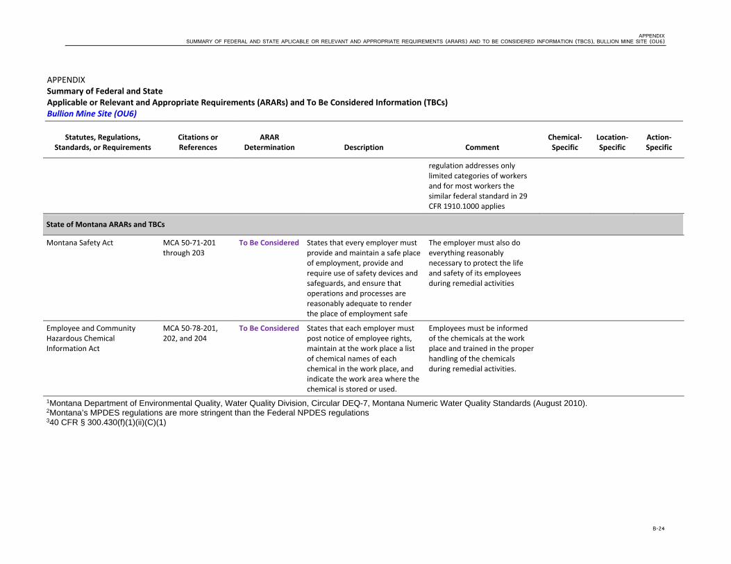
APPENDIX SUMMARY OF FEDERAL AND STATE APLICABLE OR RELEVANT AND APPROPRIATE REQUIREMENTS (ARARS) AND TO BE CONSIDERED INFORMATION (TBCS), BULLION MINE SITE (OU6)
B-24
APPENDIX Summary of Federal and State Applicable or Relevant and Appropriate Requirements (ARARs) and To Be Considered Information (TBCs) Bullion Mine Site (OU6)
Statutes, Regulations, Standards, or Requirements
Citations or References
ARAR Determination Description Comment
Chemical‐Specific
Location‐Specific
Action‐Specific
regulation addresses only limited categories of workers and for most workers the similar federal standard in 29 CFR 1910.1000 applies
State of Montana ARARs and TBCs
Montana Safety Act MCA 50‐71‐201 through 203
To Be Considered States that every employer must provide and maintain a safe place of employment, provide and require use of safety devices and safeguards, and ensure that operations and processes are reasonably adequate to render the place of employment safe
The employer must also do everything reasonably necessary to protect the life and safety of its employees during remedial activities
Employee and Community Hazardous Chemical Information Act
MCA 50‐78‐201, 202, and 204
To Be Considered States that each employer must post notice of employee rights, maintain at the work place a list of chemical names of each chemical in the work place, and indicate the work area where the chemical is stored or used.
Employees must be informed of the chemicals at the work place and trained in the proper handling of the chemicals during remedial activities.
1Montana Department of Environmental Quality, Water Quality Division, Circular DEQ-7, Montana Numeric Water Quality Standards (August 2010). 2Montana’s MPDES regulations are more stringent than the Federal NPDES regulations 340 CFR § 300.430(f)(1)(ii)(C)(1)

B-25
Acronyms ARAR Applicable or Relevant and Appropriate Requirements ARM Administrative Rules of Montana BTCA best technology currently available CFR Code of Federal Regulations EPA United States Environmental Protection Agency ESA Endangered Species Act FAA Federal Aviation Administration MCA Montana Code Annotated NEPA National Environmental Policy Act NHPA National Historic Preservation Act OU operable unit PRP potentially responsible party TBCs to be considered information U.S.C United States Code USFWS United States Fish and Wildlife Services

B-26
ARAR Determination Legend Applicable requirements refer to those cleanup standards, standards of control and other substantive environmental protection requirements, criteria or limitations under Federal or State law that specifically address hazardous substance, pollutant, contaminat, remedial action, location or other circumstances found at a CERCLA site. Only those State standards more stringent than Federal Stadards, identified in a timely manner, and applied consistently may be applicable.
Relevant and Appropriate requirements are those cleanup standards, standards of control and other substantive requirements under Federal or State environmental citing laws that, while not “applicable” to a hazardous substance, pollutant, contaminant, remedial action, location or other circumstances found at a CERCLA site address problems or situations sufficiently similar to those encountered at a CERCLA site that their use is well suited to the particular site. Only those State standards more stringent than Federal Standards, identified in a timely manner, and applied consistently may be applicable.
Regulations that are not considered environmental or facility location standards but are important regulations for remedial alternatives. These are “To Be Considered.”

Appendix B Bullion Mine Estimate Adit Discharge


BOI/5-21-09 BULLION AND CRYSTAL MINE ADIT DISCHARGE TECH MEMO.DOC 1
COPYRIGHT 2011 BY CH2M HILL, INC. • COMPANY CONFIDENTIAL
T E C H N I C A L M E M O R A N D U M
Design Flow Rates for Bullion and Crystal Mine Sites
PREPARED FOR: John Lincoln (BOI) B.T. Thomas (ATL) Gary Hickman (CVO)
PREPARED BY: CH2M HILL
DATE: February 17, 2009
The purpose of this memo is to explain the methods used to develop annual hydrographs for the mine adit discharges associated with the Bullion and Crystal Mines located in the Basin Watershed OU2, Basin, Montana. Understanding the annual variation in flow rates was essential to the development of treatment alternatives discussed in the Basin Watershed OU2 engineering evaluation and cost assessment (EE/CA).
Through an agreement with Region 8 EPA, the U.S. Geological Survey (USGS) has periodically monitored adit discharge (flow and chemical constituents) at the Bullion and Crystal mines since 1999. This information served as the basis for developing annual hydrographs. Discharge rates were plotted on a per-month basis for each mine site to create hydrographs showing annual tendencies as well as average and peak flows (Figures 1 and 2).
• Average discharge from the Bullion mine site was calculated to be approximately 0.01 CFS (4.5 GPM), with a peak flow of about 0.016 CFS (7.18 GPM) occurring during the month of July.
• Average discharge from the Crystal mine site was calculated to be approximately 0.05 CFS (22.4 GPM) with a peak flow of about 0.082 CFS (36.8 GPM) occurring during the month of July.
Annual discharge (Q) data collected by the USGS from 1929 through 2008 of the Boulder River near the town of Boulder, Montana, was reviewed and used as representative data to determine peak flow years (Figure 3). Over the past 79 years of record, it was determined that historic peak flows for the Boulder River result in approximately twice the annual flow when compared to average years. Based on this historic data, it was determined that a multiplier of two should be applied to the average adit discharge value to estimate peak discharge for high flow years for the Bullion and Crystal mines (Equation 1 and 2).
Bullion: QPeak = QAvg (4.5 gpm) x Peak Flow Multiplier (2) = 9.0 gpm…….EQ-1
Crystal: QPeak = QAvg (22.4 gpm) x Peak Flow Multiplier (2) = 44.8 gpm…...EQ-2
Application of the peak flow estimates plus associated shallow groundwater is illustrated by an independent sampling project performed by Montana State University at the Bullion Mine site. In the fall of 2004, Montana State University (MSU) measured the flow from the

DESIGN FLOW RATES FOR BULLION AND CRYSTAL MINE SITES
BOI/5-21-09 BULLION AND CRYSTAL MINE ADIT DISCHARGE TECH MEMO.DOC 2
COPYRIGHT 2011 BY CH2M HILL, INC. • COMPANY CONFIDENTIAL
upper adit of the Bullion mine during a week of heavy precipitation. Discharge from this adit plus groundwater interflow into the drainage channel between the upper adit and lower adit, as well as along Jill Creek between the Bullion mine adit discharge ditch and the confluence of Jack Creek were measured. Discharge at these locations were recorded as 13.5 gpm and 15.1 gpm, respectively (Table 1).
Table 1 Montana State University – Capstone Research Project – Bullion Mine, Basin MT Fall 2004 Measurement of total flow.
Measurement Location Total Flow (gpm)
Upper Adit 10.0
Groundwater, Upper to Middle Adit 1.6
Groundwater, Middle to Lower Adit 1.9
Subtotal 13.5
Jill Creek (Bullion Discharge to Jack Creek)
15.1
Total 28.6
Equation 3 shows the total flow rate of adit discharge and groundwater interflow that requires capture and treatment at this site.
Bullion: QTot = 10.0 gpm + 3.4 gpm + 15.1 gpm = 28.5 gpm………..EQ-3
Our previous calculations showed the need to size our treatment system by a factor of 2X to account for wet years. The adit discharge during MSU’s fall 2004 sampling was measured at 10.0 gpm which is 2.2 times the average flow (4.5 GPM) measured by the U.S. Geological Survey.
Recommendation:
Based on the measured flow during the MSU fall 2004 (Equation 3), all treatment systems for the Bullion mine are to be designed to treat up to 30 gpm.
Based on the peak flow estimate (Equation 2), all treatment systems for the Crystal mine are to be designed to treat up to 45 gpm.

0.010
0.015
0.020
0.025
Bu
llio
n M
ine D
isch
arg
e R
ate
(C
FS
)
Figure 1: Bullion Mine Discharge Rate
USGS Measured Discharge Rate
Hydrograph
Annual Average
0.000
0.005
29-Oct 18-Dec 6-Feb 28-Mar 17-May 6-Jul 25-Aug 14-Oct 3-Dec 22-Jan
Bu
llio
n M
ine D
isch
arg
e R
ate
(C
FS
)
Date
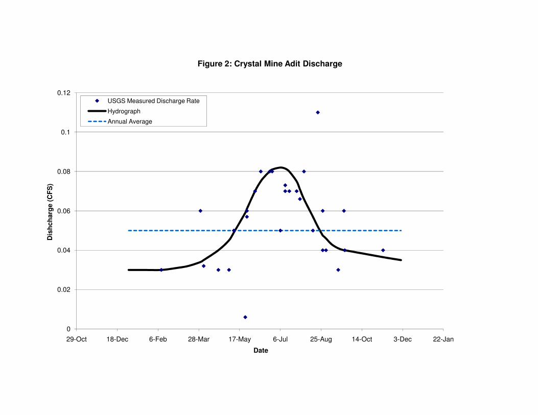
0.06
0.08
0.1
0.12
Dis
hch
arg
e (
CF
S)
Figure 2: Crystal Mine Adit Discharge
USGS Measured Discharge Rate
Hydrograph
Annual Average
0
0.02
0.04
29-Oct 18-Dec 6-Feb 28-Mar 17-May 6-Jul 25-Aug 14-Oct 3-Dec 22-Jan
Date

Appendix C Technical Memorandum(s): Mine Dewatering;
Existing Soil/Debris Plug Analysis

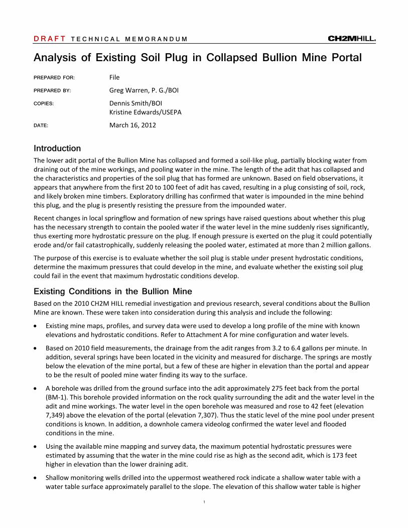
1
D R A F T T E C H N I C A L M E M O R A N D U M Analysis of Existing Soil Plug in Collapsed Bullion Mine Portal PREPARED FOR: File
PREPARED BY: Greg Warren, P. G./BOI
COPIES: Dennis Smith/BOI Kristine Edwards/USEPA
DATE: March 16, 2012
Introduction The lower adit portal of the Bullion Mine has collapsed and formed a soil‐like plug, partially blocking water from draining out of the mine workings, and pooling water in the mine. The length of the adit that has collapsed and the characteristics and properties of the soil plug that has formed are unknown. Based on field observations, it appears that anywhere from the first 20 to 100 feet of adit has caved, resulting in a plug consisting of soil, rock, and likely broken mine timbers. Exploratory drilling has confirmed that water is impounded in the mine behind this plug, and the plug is presently resisting the pressure from the impounded water.
Recent changes in local springflow and formation of new springs have raised questions about whether this plug has the necessary strength to contain the pooled water if the water level in the mine suddenly rises significantly, thus exerting more hydrostatic pressure on the plug. If enough pressure is exerted on the plug it could potentially erode and/or fail catastrophically, suddenly releasing the pooled water, estimated at more than 2 million gallons.
The purpose of this exercise is to evaluate whether the soil plug is stable under present hydrostatic conditions, determine the maximum pressures that could develop in the mine, and evaluate whether the existing soil plug could fail in the event that maximum hydrostatic conditions develop.
Existing Conditions in the Bullion Mine Based on the 2010 CH2M HILL remedial investigation and previous research, several conditions about the Bullion Mine are known. These were taken into consideration during this analysis and include the following:
Existing mine maps, profiles, and survey data were used to develop a long profile of the mine with known elevations and hydrostatic conditions. Refer to Attachment A for mine configuration and water levels.
Based on 2010 field measurements, the drainage from the adit ranges from 3.2 to 6.4 gallons per minute. In addition, several springs have been located in the vicinity and measured for discharge. The springs are mostly below the elevation of the mine portal, but a few of these are higher in elevation than the portal and appear to be the result of pooled mine water finding its way to the surface.
A borehole was drilled from the ground surface into the adit approximately 275 feet back from the portal (BM‐1). This borehole provided information on the rock quality surrounding the adit and the water level in the adit and mine workings. The water level in the open borehole was measured and rose to 42 feet (elevation 7,349) above the elevation of the portal (elevation 7,307). Thus the static level of the mine pool under present conditions is known. In addition, a downhole camera videolog confirmed the water level and flooded conditions in the mine.
Using the available mine mapping and survey data, the maximum potential hydrostatic pressures were estimated by assuming that the water in the mine could rise as high as the second adit, which is 173 feet higher in elevation than the lower draining adit.
Shallow monitoring wells drilled into the uppermost weathered rock indicate a shallow water table with a water table surface approximately parallel to the slope. The elevation of this shallow water table is higher

ANALYSIS OF EXISTING SOIL PLUG IN COLLAPSED BULLION MINE PORTAL
2
than the elevation of the water in the mine, which indicates that shallow groundwater flows downward through fractures in the rock and provides inflow into the mine.
The lower mine workings are open, rather extensive, and, based on previous estimates, it is possible that more than 2 million gallons of water are contained behind the soil plug at the present groundwater elevation. If the groundwater rises in the mine, the volume of water behind the plug could increase substantially.
Mine Plug Stability Evaluation Although the existing mine plug has remained in place with only a minor point discharge of mine water, it is important to start assessing its ability to continue without failure and potential catastrophic loss of the stored mine water. A simple way to assess the adequacy of a mine plug is to verify that the total weight of the plug exceeds the total hydraulic force exerted on it (Kirkwood and Wu, 1995). This condition is presently verified by observation, but its potential to remain in place needs to be further examined. To assess the adequacy of the plug relative to retaining the existing volume of water within the mine adit, the relationship between hydraulic head and the mine plug needs to be understood. This relationship can be expressed by the following formula:
L = PWH/WH, or P/ where:
L = Length of Plug (ft) P = hydrostatic pressure (lbs/ft2 ) W = Width of the Plug (ft) H = Height of the plug (ft) = unit weight of the plug (lbs/ft3)
Note: If the hydraulic pressures ranges are known or can be estimated, the length (and mass) of required plug can be calculated to resist the maximum anticipated hydraulic pressure. This analysis is typically used for concrete plug seals, but is applicable for use with the soil plug in the Bullion Mine.
The stability of the existing soil plug was evaluated under a variety of conditions. A stable plug length (and associated mass) was calculated for a number of anticipated hydrostatic pressures. This information was then compared to existing conditions to estimate the minimum length of the existing “soil plug”. The analysis process included the following:
1. Hydrostatic conditions were defined based on known site conditions (current state). A minimum length required for stability is calculated.
2. Various water pressure (P) conditions (height of water column) were calculated to assess the failure of variable plug lengths ranging from 20 to 100 feet.
3. Extreme hydrostatic conditions (PMAX) were calculated to determine a corresponding plug length (and associated mass) to resist those pressures. In other words, if the water rises to maximum height in the mine, would the existing plug be stable, and how long of a plug would be required for stability?
Assumptions used in this analysis include:
This analysis assumes that the plug fails catastrophically as a unit, versus slowly eroding the soil in the plug or the rock surrounding the plug.
It is assumed that the soil plug is intact; i.e. free of cracks and voids that would reduce the effective plug length, and that the plug spans the entire width and height of the adit.
This analysis neglects friction and shearing resistance between the plug and the surrounding rock, because this value is less than the internal strength of the plug, and far less than the shear strength of the surrounding rock mass.
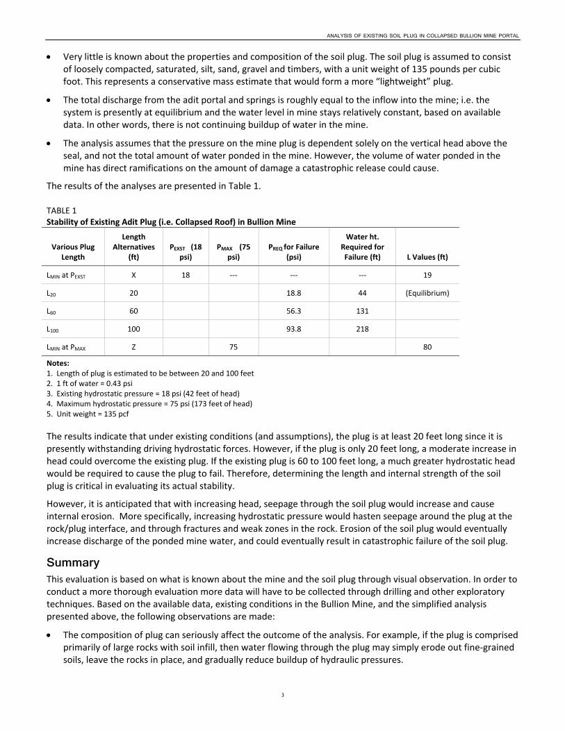
ANALYSIS OF EXISTING SOIL PLUG IN COLLAPSED BULLION MINE PORTAL
3
Very little is known about the properties and composition of the soil plug. The soil plug is assumed to consist of loosely compacted, saturated, silt, sand, gravel and timbers, with a unit weight of 135 pounds per cubic foot. This represents a conservative mass estimate that would form a more “lightweight” plug.
The total discharge from the adit portal and springs is roughly equal to the inflow into the mine; i.e. the system is presently at equilibrium and the water level in mine stays relatively constant, based on available data. In other words, there is not continuing buildup of water in the mine.
The analysis assumes that the pressure on the mine plug is dependent solely on the vertical head above the seal, and not the total amount of water ponded in the mine. However, the volume of water ponded in the mine has direct ramifications on the amount of damage a catastrophic release could cause.
The results of the analyses are presented in Table 1.
TABLE 1 Stability of Existing Adit Plug (i.e. Collapsed Roof) in Bullion Mine
Various Plug Length
Length Alternatives
(ft) PEXST (18
psi) PMAX (75
psi) PREQ for Failure
(psi)
Water ht. Required for Failure (ft) L Values (ft)
LMIN at PEXST X 18 ‐‐‐ ‐‐‐ ‐‐‐ 19
L20 20 18.8 44 (Equilibrium)
L60 60 56.3 131
L100 100 93.8 218
LMIN at PMAX Z 75 80
Notes: 1. Length of plug is estimated to be between 20 and 100 feet 2. 1 ft of water = 0.43 psi 3. Existing hydrostatic pressure = 18 psi (42 feet of head) 4. Maximum hydrostatic pressure = 75 psi (173 feet of head) 5. Unit weight = 135 pcf
The results indicate that under existing conditions (and assumptions), the plug is at least 20 feet long since it is presently withstanding driving hydrostatic forces. However, if the plug is only 20 feet long, a moderate increase in head could overcome the existing plug. If the existing plug is 60 to 100 feet long, a much greater hydrostatic head would be required to cause the plug to fail. Therefore, determining the length and internal strength of the soil plug is critical in evaluating its actual stability.
However, it is anticipated that with increasing head, seepage through the soil plug would increase and cause internal erosion. More specifically, increasing hydrostatic pressure would hasten seepage around the plug at the rock/plug interface, and through fractures and weak zones in the rock. Erosion of the soil plug would eventually increase discharge of the ponded mine water, and could eventually result in catastrophic failure of the soil plug.
Summary This evaluation is based on what is known about the mine and the soil plug through visual observation. In order to conduct a more thorough evaluation more data will have to be collected through drilling and other exploratory techniques. Based on the available data, existing conditions in the Bullion Mine, and the simplified analysis presented above, the following observations are made:
The composition of plug can seriously affect the outcome of the analysis. For example, if the plug is comprised primarily of large rocks with soil infill, then water flowing through the plug may simply erode out fine‐grained soils, leave the rocks in place, and gradually reduce buildup of hydraulic pressures.

ANALYSIS OF EXISTING SOIL PLUG IN COLLAPSED BULLION MINE PORTAL
4
The plug length is a critical component of the analysis, and this analysis assumes that the entire plug acts to retain the water. If only a portion of the plug is holding back water, then the required head to cause the plug to fail is considerably less than calculated. However, to offset this, there is a frictional/shear strength component that contributes to plug strength and is not included in this analysis.
If the existing soil plug is at least 20 feet long and free of cracks and voids, it is anticipated to be stable under the 42 feet of head measured recently. However, if the head rises higher than 42 feet it could begin to cause failure of the soil plug.
If the existing soil plug is 60 to 100 feet long, it would require approximately an additional 90 to 180 feet of head to cause failure.
At maximum head (173 feet, 75 psi), a rigid, void‐free plug a minimum of 80 feet long would be required to prevent failure, not counting increased seepage velocities through and around the plug.
Based on site observations, the plug appears to be more than 20 feet long, and thus would require more inflow into mine and an increase in hydrostatic head to cause catastrophic failure
The soil plug has been impounding water in the Bullion Mine for several years. However, if the water levels in the mine suddenly rise and the resulting hydrostatic pressures on the plug increase, seepage velocities through the soil plug, through the plug‐mine wall interface, and through fractures in the surrounding weathered granitic rock will increase. Thus, it is likely that internal erosion and piping through the soil plug could initially occur, which would begin to internally erode and de‐stabilize the plug and could potentially lead to catastrophic failure and release of a very large volume of water.
Recommendations If concerns over the integrity and stability of the existing soil plug continue, a detailed field evaluation of the existing soil plug should be conducted. Such an investigation could potentially include:
Visual observations of changes in the soil plug, adit discharge, and spring flows in the proximity
Frequent monitoring of the water levels in the adit access boring (BM‐1), especially during spring runoff and following large precipitation events
Evaluate the internal properties and estimate the length of the soil plug by drilling a series of boreholes into the soil plug and conducting Standard Penetration Testing to measure the relative density, internal strength, and obtain material samples of the plug. Analyze the actual physical properties of the plug and re‐assess its actual long‐term sustainability.
Install horizontal drains, directly measure hydrostatic pressure, and if needed, drain off the ponded water in the mine to relieve the hydrostatic pressure on the plug.
Reference Kirkwood, D. T., and Wu, K. K., 1995. Technical Considerations for the Design and Construction of Mine Seals to
Withstand Hydraulic Heads in Underground Mines.

Attachment A Subsurface Long Profile of Bullion Mine with Known
Groundwater Conditions


7,500
7,450
7,400
7,350
7,3000+00 1+00 2+00 3+00 4+00 5+00 6+00 7+00
ES062911192419BOI Attachment_A_v02.ai
ATTACHMENT A SECTION ALONG BULLION ADIT WITH KNOWN GROUNDWATER CONDITIONSBullion Mine FS
Spring Elev.
Slope = 1.5%
Rock = Weathered Granit
Open Mine Workings/Stoping
Groundwater Percolates Down to Open Workings
Dry, Collapsed
2nd Adit Controls Maximum Water Elevation
2nd Adit = 7,450’
• Plug in Adit = 20’ to 100’, Long Estmated• Consists of Saturated Soil, Rock, and Timber
Depth to Rock =10’ to 20’, 5,000 to 10,000fps
Draining Adit = 7,307, 5’x7’ Water Elevation = 7,343 - 7,349
in Mine (2010)
Boring BM-1 = 7391.7 TD-1 = 80.5’ Adit ~ 7,311
Maximum Water Level = 7,480
MW-4 Groundwater. Elevation = 7,458
NW SE
SCALE: 1” =100’ Vertical 1” = 500’ Horizontal
D R A F T


1
T E C H N I C A L M E M O R A N D U M Bullion Mine Lower Adit De-watering Concept
Kristine Edwards/USEPA
P. Dennis Smith/BOI
PREPARED BY: Rebecca Maco/SEA Jason Smesrud/PDX
DATE: May 1, 2012
Introduction The Bullion Mine, a historic underground hard rock mine, is presently the subject of a CERCLA remedial investigation and feasibility study. An interim action was taken by the USFS and EPA in 2001-02 to remove mining debris, waste rock and tailings in a joint effort. However, the site still discharges acid mine drainage (pH 2.92) from its lower workings. The lower adit portal of the Bullion Mine is collapsed and forms a soil and debris plug, which effectively blocks most water from draining out of the mine workings, resulting in water pooling back into the mine. The length of the collapsed adit and detailed characteristics and properties of the plug are unknown. Based on field observations, it appears that anywhere from the first 20 to 100 feet of adit has caved, and the resulting plug consists of soil, rock, and likely broken mine timbers. A boring drilled into the adit approximately 275 feet up gradient of the portal confirmed that a significant volume of water has pooled in the mine behind this plug (CH2M HILL 2011).
Recently, changes in flow rates of local springs and the formation of new springs have raised questions as to whether this “plug” has the necessary strength and competence to contain the pooled water. Particularly if the water in the mine rises (see CH2MHill Tech Memo dated 3/19/12), thus exerting more hydrostatic pressure on the plug, the plug could potentially erode and/or fail suddenly releasing an estimated 2 million gallons of contaminated water. EPA is considering a Time Critical Removal Action (TCRA) to prevent this potential catastrophic failure and release. The EPA Remedial Project Manager requested CH2MHill prepare a Technical Memorandum to support the need for the TCRA, and provide a concept level description of the tasks involved and estimated costs.
Therefore, the purpose of this memorandum is to present a concept level design for removing the pooled mine water, treating the water to a neutral pH, and disposing of it through a land application system. Upon completion of the mine dewatering, the collapsed portal plug debris will be removed, and the new portal will be reconstructed to facilitate the free flow of water out of the mine and into the existing discharge channel. It is anticipated that EPA will refine and implement a version of this remedial concept under a TCRA. Implementation will occur during the brief summer construction period (June through September) and be completed prior to the onset of freezing fall temperatures and winter.
Existing Conditions in the Bullion Mine Based on the 2010 CH2M HILL remedial investigation and previous research, several conditions about the Bullion Mine are known and considered during this concept approach. They include the following:
• Existing mine maps, profiles, and survey data were used to develop a long profile of the mine with known elevations and hydrostatic conditions. Refer to Figure 1 for mine profile configuration and water levels.
• Based on 2010 field measurements, drainage from the adit ranges from 3.2 to 6.4 gallons per minute (gpm). In addition, several springs have been located in the vicinity and measured for discharge. The
PREPARED FOR:
COPY TO:
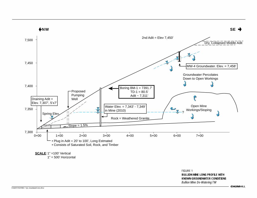
7,500
7,450
7,400
7,350
7,3000+00 1+00 2+00 3+00 4+00 5+00 6+00 7+00
ES062911192419BOI Fig1_GroundwaterCond_v04.ai
FIGURE 1 BULLION MINE LONG PROFILE WITH KNOWN GROUNDWATER CONDITIONSBullion Mine De-Watering TM
Spring Elev.
Slope = 1.5%
Rock = Weathered Granite
Open Mine Workings/Stoping
Groundwater Percolates Down to Open Workings
Dry, Collapsed Middle Adit2nd Adit = Elev 7,450’
• Plug in Adit = 20’ to 100’, Long Estmated• Consists of Saturated Soil, Rock, and Timber
Draining Adit = Elev. 7,307’, 5’x7’
Water Elev. = 7,343’ - 7,349’ in Mine (2010)
Boring BM-1 = 7391.7’ TD-1 = 80.5’ Adit ~ 7,311’
MW-4 Groundwater. Elev. = 7,458’
NW SE
SCALE: 1” =100’ Vertical 1” = 500’ Horizontal
?
Proposed Pumping Well

BULLION MINE LOWER ADIT DE-WATERING CONCEPT
3
springs are mostly below the elevation of the mine portal, but a few of these are higher in elevation than the portal and appear to be the result of ponded mine water finding its way to the surface.
• A borehole was drilled from the ground surface into the adit approximately 275 feet back from the portal (BM-1). This borehole provided information on the rock quality surrounding the adit and the water level in the adit and mine workings. The water level in the open borehole when measured, rose to 42 feet (elevation 7,349) above the elevation of the portal (elevation 7,307) indicating the static level of the mine pond under present conditions. In addition, a downhole camera videolog confirmed the water level and flooded conditions in the mine.
• Water quality at the mouth of the adit has been sampled on a quarterly basis by the USGS from 1999 to 2011. The adit discharge was also sampled independently by CH2M HILL in 2010 as part of a site remedial investigation. A summary of that data is included in Table 1.
• Shallow monitoring wells drilled into the uppermost weathered rock indicate a shallow water table. The elevation of this shallow water table is higher than the elevation of the water in the mine, which indicates that shallow groundwater flows downward through fractures in the rock and is likely a source of inflow into the mine.
• The lower mine workings are open and rather extensive, and based on previous estimates it is possible that more than 2 million gallons of water are contained behind the soil plug at the present groundwater elevation. If the groundwater rises in the mine, the volume of water behind the plug could increase substantially.
The following sections present a concept level approach for dewatering, treating, and disposal of the existing mine water which will allow removal of the existing mine plug and facilitate the free flow of mine drainage into the existing drainage trench.
Mine De-watering To access the pooled mine water, a new boring will be drilled into the lower adit between the collapsed portal plug and the existing boring BM-1 (See Figure 1) and constructed as a monitoring well. The boring will need to be relatively close to the upgradient end of the portal plug to allow as complete dewatering as possible prior to removal of the collapsed portal material.
The boring will be drilled using a 6 or 8-inch-diameter air rotary or downhole hammer. The monitoring well will be constructed in compliance with ASTM D5092 Standard Practice for design and Installation of Ground Water Monitoring Wells in Aquifers and Montana Department of Water Resources Monitoring Well Construction rules.
The monitoring well casing and screen will consist of threaded, flush-jointed, 4-inch-diameter, Schedule 40 or 80 PVC. A 20-foot section of factory-slotted screen will be installed at the bottom of the well and extend the full height of the adit. No filter pack will be needed as the screened section will extend to the floor of the adit. A packer should be placed above screen section in host rock, and bentonite chips or grout will be poured in the boring annulus above the packer to provide a seal to within 1 foot of the ground surface. No development of the monitoring well is necessary. The well will be finished with above-ground monument that consists of an 8-inch-diameter steel casing cemented into the ground with approximately 2 to 3 feet of stickup and a locking cover.
A submersible pump powered by an on-site diesel powered generator and capable of pumping at least 40 gpm will be utilized to pump mine water into the treatment system. Prior to initiating pumping, the static water level within the new well and well BM-1 will be measured and recorded. Monitoring well BM-1 provides a consisent monitoring port through which the static water level in the lower adit can be monitored throughout the dewatering process.

BULLION MINE LOWER ADIT DE-WATERING CONCEPT
4
Treatment Process and Assumptions A summary of the available water quality data is provided in Table 1. The mine water is generally characterized by low pH (in the ~2.5 – 3.0 range), relatively high iron and sulfate, and dissolved metals including cadmium (Cd), copper (Cu), lead (Pb), zinc (Zn), and arsenic (As).
TABLE 1 Summary of Mean Water Chemistry Data, Bullion Mind Adit
Parameter
Mean USGS Data
Sept 1999 - Nov 2011 Units
Air Temperature 9.9 Degrees C
pH (field) 3.0
pH (lab) 2.8
Specific Conductivity (lab) 1,916 µS/cm
Specific Conductivity (field) 1,844 µS/cm
Water Temperature 5.2 Degrees C
Ca 81.4 mg/L
Mg 30.9 mg/L
Cd (dissolved) 435 µg/L
Cd (total) 442 µg/L
Cu (dissolved) 8,121 µg/L
Cu (total) 8,647 µg/L
Pb (dissolved) 402 µg/L
Pb (total) 453 µg/L
Zn (dissolved) 47,769 µg/L
Zn (total) 50,784 µg/L
As(dissolved) 2,484 µg/L
As (total) 3,567 µg/L
TSS, 62.5 µm 99 mg/L
TSS 137 mg/L
Parameter
Average Result, Sampling Conducted in July and September,
2010 Units
Na 5.02 mg/L
K 2.955 mg/L
Ca 74.1 mg/L
Mg 29.9 mg/L
Fe 218.5 mg/L
Mn 26.6 mg/L
Cl <1 mg/L
Alkalinity <5 mg/L
SO4 1,255 mg/L
ORP 401 mV
Turbidity 7.2 NTU
DO 7.03 mg/L

BULLION MINE LOWER ADIT DE-WATERING CONCEPT
5
EPA has determined the design basis of the treatment system to be neutralization (increase in pH) to between pH 6 and pH 8. A conceptual treatment approach has been developed to achieve this design basis. A process flow diagram for this conceptual treatment approach is shown in Figure 2. In addition to neutralization within the stated pH range (6 to 8), it is expected that the system will result in precipitation of iron and, along with the iron, co-precipitation of some of the trace metals present in the water.
FIGURE 2 Conceptual Process Flow Diagram, Adit Water Treatment System
It has been estimated that approximately 2 million gallons of water may require removal to dewater the mine during the estimated 75 day window for site work during the summer of 2012. Based on these constraints, a design flow for the treatment system of 40 gallons per minute (gpm) was determined.
The treatment system will consist of a series of reaction tanks, followed by a settling pond. Each component of the system is described as follows:
• Reaction Tank 1 (Neutralization Reactor). The objective of Reaction Tank 1 is to react the mine water with powdered limestone to increase the pH. Powdered limestone will be delivered to the site as a powder and will be mixed with water in a slurry tank before injection into Reaction Tank 1. The dose of powdered limestone (as CaCO3) is estimated to be 1,560 milligrams per liter, or 13 tons over the course of treatment. Reactor Tank 1 will include a mechanical mixer, estimated at 1 horsepower (HP) in size. The reaction with limestone will evolve carbon dioxide and lead to foaming at the water surface. Reactor Tank 1 will be aerated to help strip this carbon dioxide out of solution, thus increasing the pH. To allow sufficient time for reaction, this tank has been sized for a 30 minute hydraulic retention time. Due to the foaming mentioned above, the freeboard on this tank should be approximately one third of the total tank height. Foam suppression sprays might also be needed. The total tank volume of Reaction Tank 1 is estimated to be 1,200 gallons. This volume could be split into more than one tank if that were preferable for transport and placement at the site.
• Reaction Tank 2 (Aeration Reactor). The objective of Reaction Tank 2 is to oxidize the iron in solution so that it, along with other metals, will precipitate in the settling pond. This precipitation of solids in solution is needed because the treated water will be land applied. If iron oxides and are left in solution, they would inhibit percolation of water through the soil. Reactor Tank 2 will be aerated to provide oxygen for the oxidation of iron. To allow sufficient time for iron oxidation, this tank has been sized for a 45 minute hydraulic retention time. The total tank volume of Reaction Tank 2 is estimated to be 1,800 gallons. For cost estimating purposes, it is assumed that Reaction Tank 2 will be split into two 900 gallon

BULLION MINE LOWER ADIT DE-WATERING CONCEPT
6
tanks (2A and 2B). Reactor Tanks 2A and 2B will include mechanical mixers, estimated at 1 HP in size, each.
• Reaction Tank 3 (Contingent pH Adjustment). If the pH is not within the desired range following Reaction Tank 2, a third Reaction Tank would be used to further increase the pH using a caustic (sodium hydroxide) solution at a dose of 100 parts per million. Reactor Tank 3 will also be aerated for continued oxidation of iron to the ferric state. To allow sufficient time for reaction with the caustic solution, this tank has been sized for a 20 minute hydraulic retention time. The total tank volume of Reaction Tank 3 is estimated to be 900 gallons. Costs have been included for this contingency tank, although if time allows for bench-scale testing of this treatment approach prior to implementation, it may be possible to demonstrate that this contingency step is not needed.
• Settling Pond. The settling pond will allow sufficient residence time for sedimentation of iron sludge. The pond will be constructed with baffles to elongate the flow path and prevent short circuiting. It is estimated that after settling, the settled sludge concentration in the bottom of the pond will be 5 percent solids. At this concentration, it is estimated that a total volume of just over 40,000 gallons of sludge will be generated over the course of treatment. The minimum surface area of the pond is determined by the hydraulic loading rate, assumed to be 0.1 gpm/square foot. The depth of the pond is dependent on the desired cleanout frequency and accumulated sludge volume between cleanouts. It is recommended that the minimum size for the pond be 400 square feet in surface area and 10 feet total depth. At this size, cleanout by vacuum truck would be required once per week. If it is possible to increase the size of the pond during design, the cleanout frequency can be reduced (See Figure 3 as an example of a settling pond). It is assumed that the sludge will be transported to the nearby Luttrell repository for disposal and the treated water will be conveyed to the land application system.
In addition to the system components discussed above, a compressor, or series of compressors, capable of supplying a total of 32 actual cubic feet per minute (ACFM) (8 HP) will be needed to provide aeration of the reaction tanks.
Land Application Concept and Assumptions Land application of the treated mine water is the final component of the conceptual mine de-watering process.
A viable plan for land application of the treated water will need to address the following issues:
- Land suitability for irrigation based on vegetation, slope, aspect, topographic position, and soil - Potential impacts to vegetation and soil based on treated water quality - Irrigation water budget for selected vegetation to determine land application area needs - Drainage basins and potential hydrologic discharge pathways of applied water - Land ownership of target land application areas - Potential irrigation application methods - Irrigation water pumping and conveyance needs - Order of magnitude costs and operations and maintenance requirements
The purpose of this section is to address these issues and present a conceptual plan for land application of the treated water.
As previously described, the estimated volume of water that will be removed through dewatering of the mine adit is 2 million gallons. It is assumed that this dewatering would occur during a 75-day period from July through mid-September at a pumping rate of ranging from 30 to 40 gallons per minute (gpm). The treated water would be land applied through an irrigation system located away from the underground workings.


BULLION MINE LOWER ADIT DE-WATERING CONCEPT
8
Site Description The Bullion Mine is located approximately 6 miles to the north of Basin, MT , is surrounded by U.S. Forest Service (USFS) land, and ranges in elevation from approximately 7100 to 7800 ft.
Land within the claim boundary generally slopes to the north and northwest and ranges in slope from 18 to 50 percent. However, the majority of the area within the claim boundary is at slopes of 25 percent and greater.
Climate Meteorological conditions in the upper Basin Creek Watershed are continuously monitored at three locations: Basin Creek Snow Telemetry (SNOTEL) Station (7180 feet amsl), Frohner Meadow (6480 feet amsl), and Rocker Peak (8000 feet amsl). The Rocker Peak Station is less than 3 miles to the east of the site and has been used for characterizing the climate at the Bullion Mine site.
The Bullion Mine site receives an average annual precipitation of approximately 29 inches. The highest precipitation period generally occurs in May, June, and July (see Table 2). Temperature extremes range from highs near 85 degrees Fahrenheit (°F) in late summer to lows near -40°F in December and January. The average temperatures at the Rocker Station during the coldest months of December and January are between 17° and 23°F. July and August are the warmest months with average temperature in the low 50°F range. Snow accumulation typically occurs between October and March with snow melt proceeding up through June.
TABLE 2 Average Monthly Temperature, Precipitation, and Evapotranspiration at the Rocker Peak SNOTEL Site
Location Jan Feb Mar Apr May Jun Jul Aug Sep Oct Nov Dec Annual
Average Temperature (ºF)
Rocker Peak a 19 19 23 29 37 44 53 52 44 33 23 17
Precipitation (inches)
Rocker Peak a 2.2 1.9 2.3 3.2 3.5 4.2 2.7 1.7 2.0 1.0 2.1 2.3 29.1
Reference Grass Evapotranspiration (inches)
Rocker Peak b 0.6 0.8 1.5 2.3 3.3 4.1 5.0 4.3 2.7 1.5 0.7 0.5 27.5
Sources: a Natural Resources and Conservation Service 2011 b Calculated using REF-ET software (Allen, 2012)
Reference evapotranspiration (ETo) was estimated using the REF-ET software (Allen, 2012) and using daily air temperature and site elevation and latitude data from the Rocker Peak Station over the period of 1984 through 2011. Although the annual average ETo of 27.5 inches is lower than the annual average precipitation (29.1 inches), ETo does exceed precipitation during the planned irrigation months of July through September. Average ETo during this period is 12 inches compared to average precipitation totals of 6.4 inches. Soil moisture and temperature data is not collected at the Rocker Peak Station. However, these parameters are measured at the Nevada Ridge SNOTEL station (7020 feet amsl) located approximately 35 miles to the northwest of the Bullion Mine site. Plots of soil moisture and temperature at depths of 4-, 8-, 20-, and 40-inches below ground from 2009, 2010, and 2011 are presented in Attachment A. These data show that soils generally freeze up in November and remain frozen or at near freezing temperatures until sometime in June. Soil temperatures generally warm up to 5 degrees C or above by the beginning of July, at which time soil moisture levels start declining due to evapotranspiration (ET) losses. Over the period from the beginning of July through the end of
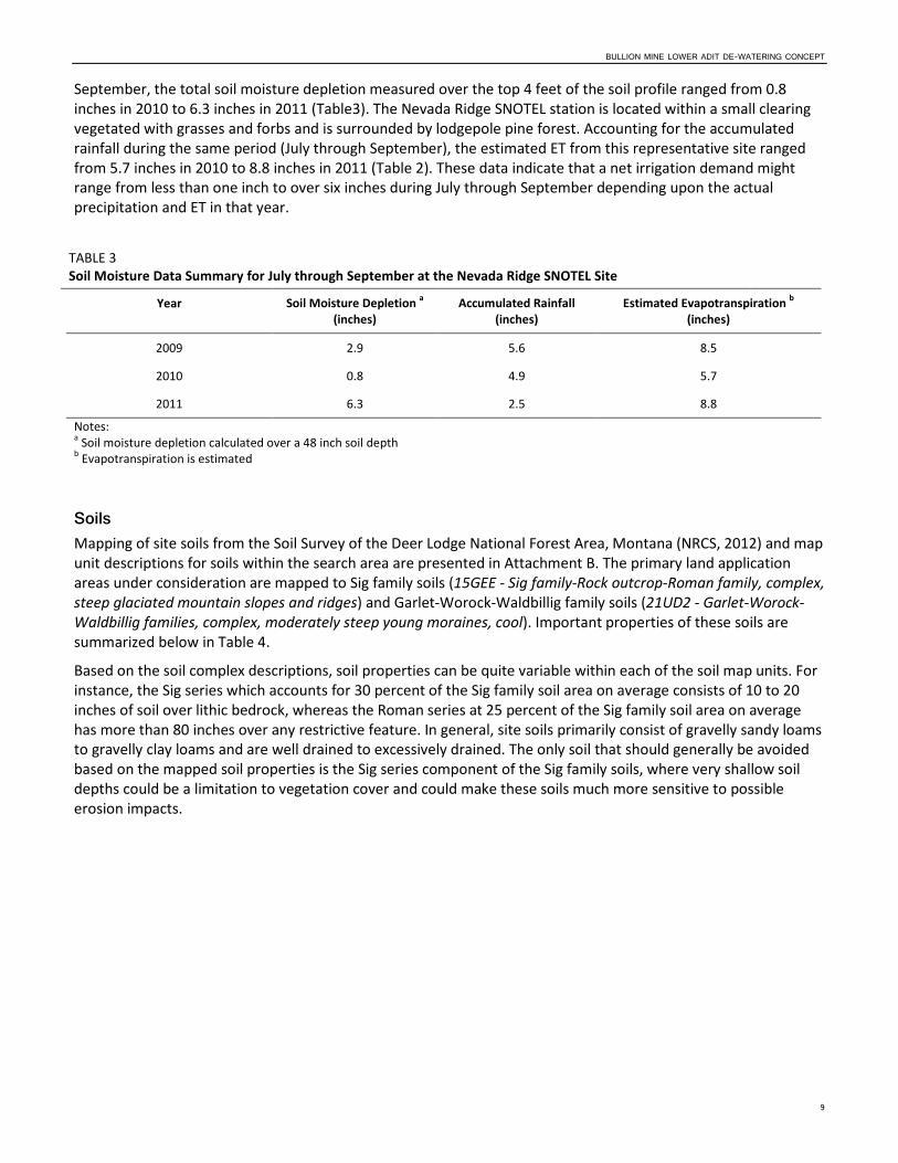
BULLION MINE LOWER ADIT DE-WATERING CONCEPT
9
September, the total soil moisture depletion measured over the top 4 feet of the soil profile ranged from 0.8 inches in 2010 to 6.3 inches in 2011 (Table3). The Nevada Ridge SNOTEL station is located within a small clearing vegetated with grasses and forbs and is surrounded by lodgepole pine forest. Accounting for the accumulated rainfall during the same period (July through September), the estimated ET from this representative site ranged from 5.7 inches in 2010 to 8.8 inches in 2011 (Table 2). These data indicate that a net irrigation demand might range from less than one inch to over six inches during July through September depending upon the actual precipitation and ET in that year.
TABLE 3 Soil Moisture Data Summary for July through September at the Nevada Ridge SNOTEL Site
Year Soil Moisture Depletion a (inches)
Accumulated Rainfall (inches)
Estimated Evapotranspiration b (inches)
2009 2.9 5.6 8.5
2010 0.8 4.9 5.7
2011 6.3 2.5 8.8
Notes: a Soil moisture depletion calculated over a 48 inch soil depth b Evapotranspiration is estimated
Soils Mapping of site soils from the Soil Survey of the Deer Lodge National Forest Area, Montana (NRCS, 2012) and map unit descriptions for soils within the search area are presented in Attachment B. The primary land application areas under consideration are mapped to Sig family soils (15GEE - Sig family-Rock outcrop-Roman family, complex, steep glaciated mountain slopes and ridges) and Garlet-Worock-Waldbillig family soils (21UD2 - Garlet-Worock-Waldbillig families, complex, moderately steep young moraines, cool). Important properties of these soils are summarized below in Table 4.
Based on the soil complex descriptions, soil properties can be quite variable within each of the soil map units. For instance, the Sig series which accounts for 30 percent of the Sig family soil area on average consists of 10 to 20 inches of soil over lithic bedrock, whereas the Roman series at 25 percent of the Sig family soil area on average has more than 80 inches over any restrictive feature. In general, site soils primarily consist of gravelly sandy loams to gravelly clay loams and are well drained to excessively drained. The only soil that should generally be avoided based on the mapped soil properties is the Sig series component of the Sig family soils, where very shallow soil depths could be a limitation to vegetation cover and could make these soils much more sensitive to possible erosion impacts.
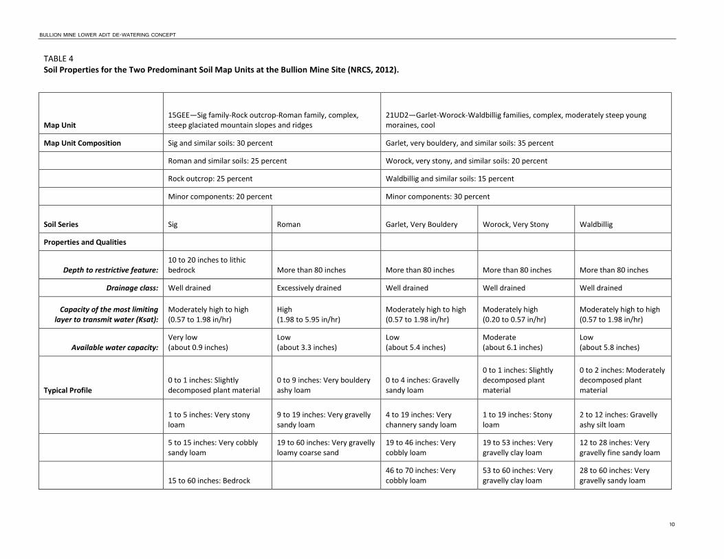
BULLION MINE LOWER ADIT DE-WATERING CONCEPT
10
TABLE 4 Soil Properties for the Two Predominant Soil Map Units at the Bullion Mine Site (NRCS, 2012).
Map Unit 15GEE—Sig family-Rock outcrop-Roman family, complex, steep glaciated mountain slopes and ridges
21UD2—Garlet-Worock-Waldbillig families, complex, moderately steep young moraines, cool
Map Unit Composition Sig and similar soils: 30 percent Garlet, very bouldery, and similar soils: 35 percent
Roman and similar soils: 25 percent Worock, very stony, and similar soils: 20 percent
Rock outcrop: 25 percent Waldbillig and similar soils: 15 percent
Minor components: 20 percent Minor components: 30 percent
Soil Series Sig Roman Garlet, Very Bouldery Worock, Very Stony Waldbillig
Properties and Qualities
Depth to restrictive feature:
10 to 20 inches to lithic bedrock More than 80 inches More than 80 inches More than 80 inches More than 80 inches
Drainage class: Well drained Excessively drained Well drained Well drained Well drained
Capacity of the most limiting layer to transmit water (Ksat):
Moderately high to high (0.57 to 1.98 in/hr)
High (1.98 to 5.95 in/hr)
Moderately high to high (0.57 to 1.98 in/hr)
Moderately high (0.20 to 0.57 in/hr)
Moderately high to high (0.57 to 1.98 in/hr)
Available water capacity: Very low (about 0.9 inches)
Low (about 3.3 inches)
Low (about 5.4 inches)
Moderate (about 6.1 inches)
Low (about 5.8 inches)
Typical Profile 0 to 1 inches: Slightly decomposed plant material
0 to 9 inches: Very bouldery ashy loam
0 to 4 inches: Gravelly sandy loam
0 to 1 inches: Slightly decomposed plant material
0 to 2 inches: Moderately decomposed plant material
1 to 5 inches: Very stony loam
9 to 19 inches: Very gravelly sandy loam
4 to 19 inches: Very channery sandy loam
1 to 19 inches: Stony loam
2 to 12 inches: Gravelly ashy silt loam
5 to 15 inches: Very cobbly sandy loam
19 to 60 inches: Very gravelly loamy coarse sand
19 to 46 inches: Very cobbly loam
19 to 53 inches: Very gravelly clay loam
12 to 28 inches: Very gravelly fine sandy loam
15 to 60 inches: Bedrock
46 to 70 inches: Very cobbly loam
53 to 60 inches: Very gravelly clay loam
28 to 60 inches: Very gravelly sandy loam

BULLION MINE LOWER ADIT DE-WATERING CONCEPT
11
Vegetation and Surface Cover Vegetation on site is typical of high altitude forest and meadows. A portion of the site is covered by lodgepole pine dominated forest of varying stand age with generally sparse understory and a fair amount of windfall (Photo 1 ). Several stands of beetle-kill lodgepole forest are present in the vicinity. Other areas that have been reclaimed consist of predominantly perennial bunchgrass and forbs (Photo 2) at approximately 50 percent aerial vegetation coverage. Some areas are also dominated by large surface boulders deposited as glacial till (Photo 3). While land application could be located within any of these cover types, final irrigation designs will need to consider the potential limitations within each area. In locations with large surface boulders for instance, spray head densities should be reduced proportional to the amount of surface area that is covered by boulders. Locations with dense windfall within forest stands may also need to be avoided to facilitate easy access for installation and maintenance of the irrigation application system.
Irrigation Water Budget and Water Quality Irrigation Water Budget An irrigation water budget was developed in order to estimate irrigation volumes and schedules and to assess the potential hydrologic impact of irrigation land application of the treated water. The irrigation water budget was conducted only for the growing season months of July through September and accounts for total and effective precipitation, reference and crop evapotranspiration (ET), and infiltration losses that will result in recharge below the crop root zone during the irrigation season months. Two plant communities were chosen in developing the water budgets:
1) lodgepole pine forest with a full canopy; and
2) native grasses with an estimated 50% ground cover
Crop coefficients for estimating ET demands were taken as 1.0 for lodgepole pine forest and 0.71 based on a 50% aerial plant cover in the native grass community (Allen et al, 1998).
Irrigation water budgets were developed for two primary scenarios:
1) minimal recharge whereby irrigation is applied at agronomic rates to satisfy ET losses during July through September; and
2) high recharge whereby irrigation is applied at approximately double the agronomic rates on half the acreage (Given the temporary nature of this activity, operating the land application system strictly within the guidelines of agronomic rates may be overly restrictive. Consequently, an approximate doubling of application rates over agronomic irrigation demands was evaluated to reduce the required land application area)
Complete water budget calculations are presented in Attachment C and results are summarized below in Table 5.
Evapotranspiration rates for native grasses in the irrigation water budget compared well with ET estimates provided by analysis of SNOTEL data (Table 2). Native grass ET over the July through September period was estimated at 8.5 inches in the irrigation water budget compared to the SNOTEL estimated ET of 5.7 to 8.8 inches. The average net irrigation water requirements in the irrigation water budgets were estimated at 5 inches for native grasses and up to 8.2 inches for lodgepole pine stands.
The irrigation water budget results suggest that a land application area of between 7 and 12 acres would be required for the minimal recharge or agronomic rate scenario. For the high recharge scenario, land application area requirements could be reduced down to 3.5 to 6 acres.
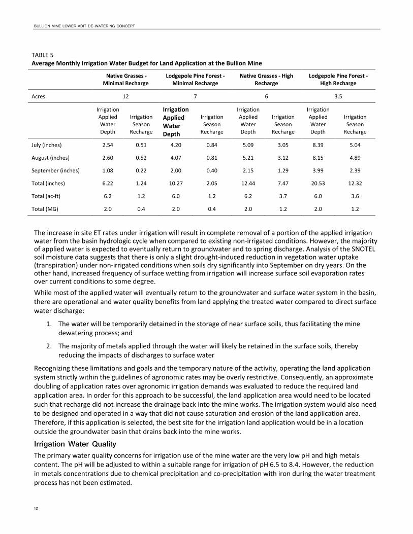
BULLION MINE LOWER ADIT DE-WATERING CONCEPT
12
TABLE 5 Average Monthly Irrigation Water Budget for Land Application at the Bullion Mine
Native Grasses - Minimal Recharge
Lodgepole Pine Forest - Minimal Recharge
Native Grasses - High Recharge
Lodgepole Pine Forest - High Recharge
Acres 12 7 6 3.5
Irrigation Applied Water Depth
Irrigation Season
Recharge
Irrigation Applied Water Depth
Irrigation Season
Recharge
Irrigation Applied Water Depth
Irrigation Season
Recharge
Irrigation Applied Water Depth
Irrigation Season
Recharge
July (inches) 2.54 0.51 4.20 0.84 5.09 3.05 8.39 5.04
August (inches) 2.60 0.52 4.07 0.81 5.21 3.12 8.15 4.89
September (inches) 1.08 0.22 2.00 0.40 2.15 1.29 3.99 2.39
Total (inches) 6.22 1.24 10.27 2.05 12.44 7.47 20.53 12.32
Total (ac-ft) 6.2 1.2 6.0 1.2 6.2 3.7 6.0 3.6
Total (MG) 2.0 0.4 2.0 0.4 2.0 1.2 2.0 1.2
The increase in site ET rates under irrigation will result in complete removal of a portion of the applied irrigation water from the basin hydrologic cycle when compared to existing non-irrigated conditions. However, the majority of applied water is expected to eventually return to groundwater and to spring discharge. Analysis of the SNOTEL soil moisture data suggests that there is only a slight drought-induced reduction in vegetation water uptake (transpiration) under non-irrigated conditions when soils dry significantly into September on dry years. On the other hand, increased frequency of surface wetting from irrigation will increase surface soil evaporation rates over current conditions to some degree. While most of the applied water will eventually return to the groundwater and surface water system in the basin, there are operational and water quality benefits from land applying the treated water compared to direct surface water discharge:
1. The water will be temporarily detained in the storage of near surface soils, thus facilitating the mine dewatering process; and
2. The majority of metals applied through the water will likely be retained in the surface soils, thereby reducing the impacts of discharges to surface water
Recognizing these limitations and goals and the temporary nature of the activity, operating the land application system strictly within the guidelines of agronomic rates may be overly restrictive. Consequently, an approximate doubling of application rates over agronomic irrigation demands was evaluated to reduce the required land application area. In order for this approach to be successful, the land application area would need to be located such that recharge did not increase the drainage back into the mine works. The irrigation system would also need to be designed and operated in a way that did not cause saturation and erosion of the land application area. Therefore, if this application is selected, the best site for the irrigation land application would be in a location outside the groundwater basin that drains back into the mine works.
Irrigation Water Quality The primary water quality concerns for irrigation use of the mine water are the very low pH and high metals content. The pH will be adjusted to within a suitable range for irrigation of pH 6.5 to 8.4. However, the reduction in metals concentrations due to chemical precipitation and co-precipitation with iron during the water treatment process has not been estimated.

BULLION MINE LOWER ADIT DE-WATERING CONCEPT
13
An in depth analysis of potential water quality impacts to vegetation was not conducted as part of this analysis. Such an analysis would require further information on background soil chemical conditions and vegetation within the proposed land application area and an estimate of the treated water metal concentrations. However, an evaluation of potential loading rates of metals from irrigation of untreated water is presented below in Table 6.
Using the cumulative metal mass loading limits employed by EPA for regulation of biosolids applications (40 CFR 503), annual mass loading rates were compared to the allowed cumulative pollutant loading rates and the site life was calculated. These limits were developed for application of biosolids to agricultural lands and are designed to maintain soil productivity without long-term limitations for continued agricultural use. Based on this analysis, the lowest site life for the metals analyzed is 4 years for application of Arsenic. Zinc is the next most limiting constituent with a site life of 18 years.
TABLE 6 Estimated Annual Mass Loading of Metals from Irrigation Land Application of Untreated Water at the Bullion Mine
Adit Water Quality -
Untreated Annual Mass
Loading Rate a
Allowed Cumulative Pollutant Loading Rate
(40 CFR 503) Site Life
mg/L lb/ac/yr [kg/ha] [lb/ac] Years
Arsenic 3.45 9.7 41 36.5 4
Cadmium 0.42 1.2 39 34.7 30
Copper 10.24 28.9 1,500 1335.5 46
Lead 0.54 1.5 300 267.1 176
Zinc 49.95 140.8 2,800 2492.8 18
Notes: a Loading rates calculated for an annual irrigation application depth of 12.44 inches.
The past history of mine tailings disposal and background metals concentrations in site soils that might be used for land application areas is unknown. Without further information, we cannot say at this time whether the planned loading rates could be detrimental to site vegetation or long-term soil productivity.
Potential Land Application Areas In order to reduce the potential erosion risk from irrigating on steep slopes, areas with slopes of less than 20 percent should be targeted. The nearest location meeting this criterion lies primarily on USFS land bordering the mine claim to the southwest. As shown in Figure 4, the proposed location is approximately 9.7 acres in area and has slopes ranging between approximately 5 to 20 percent. This area slopes away from Jill Creek but still drains to Jack Creek. Another advantage of this location over most areas inside the claim boundary is that groundwater drainage would likely be away from the mine shaft, thereby reducing the potential for irrigation recharge short-circuiting the dewatering process. Within this area, a high rate irrigation strategy could be utilized to minimize the total land application area required. This site also has a west facing aspect compared to the north to northwest facing aspect of most sites within the claim boundary, which should allow for higher ET rates.
Prior to moving forward with a final site selection and design, discussion with the USFS would be required. This area should also be investigated for soil conditions and vegetation/surface conditions to identify any potential irrigation exclusion areas.


\\O
WL\
PR
OJ\
EPA
\408
158B
ULL
ION
MIN
E\G
IS\M
AP
FILE
S\W
ATE
RS
HED
.MX
D J
CA
RR
3 6/
21/2
011
08:1
3:13
VICINITY MAP
Notes:1. Area of interest subject to change.2. 2009 NAIP Orthophotography
Jill Creek
0050 250
Feet
LEGENDDrainageAdit Discharge ChannelMajor Contour (10m)Minor Contour (2m)Mine Claim Boundary
$
FIGURE 4PROPOSED LAND APPLICATION AREABullion Mine De-Watering TM
ES062911192419BOI Fig4_ProposedLandApplicationArea_v03.ai
Adit Discharge
Proposed Settling Pond Location
Proposed Land Application Area (approx.
9.7 acres)
2300 m
2200 m

BULLION MINE LOWER ADIT DE-WATERING CONCEPT
15
Irrigation System Conceptual Design Irrigation Application System Due to the steep slopes on site, irrigation application systems would be limited to low rate sprinkler or micro-irrigation systems. The maximum sprinkler application rates recommended by NRCS for silt loam soils on 12 to 16 percent slopes (the highest slope classification considered) and less than full vegetation cover is 0.15 inches per hour (USDA NRCS, National Engineering Handbook, Section 15, Irrigation, Chapter 11, Sprinkle Irrigation). The rate should also be lower than the capacity of the most limiting soil layer to transmit water, which could be as low as 0.20 inches per hour (Table 3). Application rates this low are typically only achieved with low-flow micro-spray sprinklers.
Micro-irrigation application systems typically used in tree orchards with spray heads ranging from 0.35 to 1.5 gpm operated at 25 to 50 pounds per square inch (psi) pressure could be used for this application. Flexible polyethylene tubing ranging in diameter from 0.5 to 1.0 inches that is laid on the ground surface is a common water supply method. Spray heads are typically installed on stakes and are supplied by small diameter (0.25 inch) feed tubes that connect to the supply tube through push-in barbed connectors. Because the throw radius of these low flow spray heads is usually only 18 to 30 feet, sprinklers are typically installed on relatively close spacings.
For planning purposes and to provide a basis for costing, a conceptual design with specific irrigation hardware is described here. The basis for irrigation rates and areas will assume the native grass high rate option with a total irrigated area of 6 acres. The conceptual design involves the use of Nelson R-10 spray heads with 0.35 gpm flow control nozzles. The flow control nozzles are selected because they are pressure compensating over the range of 25 to 50 psi and non-compensated heads used on the steep site slopes may otherwise provide uneven water distribution. Spray laterals of 1.0 inch diameter would be installed on 20 foot spacing with a head to head spacing down the tubes of 20 feet. With this spray head density, the average instantaneous application rate would be 0.08 inches per hour.
In order to match field application system flows to the pumping flows, irrigation areas would be valved into several different zones. Assuming a 30 gpm design flow, 86 spray heads would be supplied within each irrigation zone covering 0.79 acres. Assuming a 6 acre land application area, a total of 8 separately valved irrigation zones would be laid out. The limits of each zone should be laid out with no more than approximately 46 feet (20 psi equivalent) of elevation change from the highest to lowest spray head and the water supply pressure should be at least 25 psi at the highest spray head in each zone.
Irrigation Pumping and Conveyance Conveyance of water from the treatment process settling pond to the land application area will involve a pump and small sump and a 2 inch diameter PVC mainline laid on the ground surface from the pumping site out to each spray lateral. For planning purposes, it is assumed that the water treatment system (settling pond) will be located at an elevation of about 2265 m (7430) ft and the irrigation area elevation will be located approximately 500 feet away at an elevation of 2230 to 2260 m (7317 to 7415 ft). Assuming an average irrigation pressure of 45 psi, the total dynamic head requirement is 180 feet. With a flow rate of 30 gpm, the brake horsepower required for the irrigation pump is 2 hp.
Irrigation Operations Scheduling of the water treatment process and irrigation operations will need to be coordinated to avoid the need for water storage. Assuming a peak month irrigation application of 5 inches and a 0.08 inch per hour application rate, each zone will be irrigated for 62.5 hours per month. Over the 8 irrigation zones, the total irrigation operational time each month will be 500 hours. Consequently, the water treatment and irrigation system only need to operate for approximately 70% of a 24/7 schedule during the peak month.

BULLION MINE LOWER ADIT DE-WATERING CONCEPT
16
Rough Order of Magnitude Costs (ROM)
A ROM cost estimate was prepared based on the conceptual dewatering approach described in this memo. A summary is provided in Table 7. Individual line items comprising the cost estimate are presented in Attachment D.
Table 7
Summary of Estimated Costs Based on Conceptual Dewatering Approach
Activities Estimated Cost1
Mob/Demob $32,000
Sitework $166,221
Treatment $171,203
Land Application $46,570
Contingency $103,998
CM/PM/Design $137,278
TOTAL CAPITAL ESTIMATE $657,270
O&M $435,567
Contingency $108,892
Admin $54,446
TOTAL O&M ESTIMATE $598,905
PROJECT ESTIMATE $1,256,175 1) The cost estimate shown has been prepared for guidance in project evaluation from the information available at the time of the ROM estimate. The final cost of the project will depend on final design, selected scope of work, actual labor and material costs, competitive market conditions, implementation schedule and other variable factors. As a result, the final project costs will vary from the ROM estimate presented herein.

CH2M HILL. 2012. ANALYSIS OF EXISTING SOIL PLUG IN COLLAPSED BULLION MINE PORTAL, BULLION MINE, OPERABLE UNIT 6, JEFFERSON COUNTY, MONTANA. PREPARED FOR U.S. ENVIRONMENTAL PROTECTION AGENCY, REGION 8, HELENA, MONTANA. MARCH.
17
References Allen, R.G., L.S. Pereira, D. Raes, and M. Smith. 1998. Crop Evapotranspiration: Guidelines for Computing Crop Water Requirements. FAO Irrigation and Drainage Paper No. 56. Food and Agriculture Organization (FAO) of the United Nations, Rome, Italy. Allen, R.G. 2012. REF-ET: Reference Evapotranspiration Calculation Software for FAO and ASCE Standardized Equations. Version 3.1.07 for Windows. University of Idaho, 2012. Ayers, R.S. and D.W. Westcot. 1989. Water Quality for Agriculture. FAO Irrigation and Drainage Paper No. 29 rev. 1. Food and Agriculture Organization of the United Nations, Rome. CH2M HILL. 2011. Draft Focused Remedial Investigation, Bullion Mine, Operable Unit 6, Jefferson County, Montana. Prepared for U.S. Environmental Protection Agency, Region 8, Helena, Montana. July.
CH2M HILL. 2012. Analysis of Existing Soil Plug in Collapsed Bullion Mine Portal, Bullion Mine, Operable Unit 6, Jefferson County, Montana. Prepared for U.S. Environmental Protection Agency, Region 8, Helena, Montana. March.
Natural Resources Conservation Service (NRCS). 2012. Data accessed from Web Soil Survey (http://websoilsurvey.nrcs.usda.gov/app/HomePage.htm) on April 18, 2012.


Photos

BULLION MINE LOWER ADIT DE-WATERING CONCEPT
Photos
Photo 1. Typical Lodgepole Pine Forest Cover at the Bullion Mine Site.
Photo 2. Typical Grass Cover at the Bullion Mine Site.

Photo 3. Area Dominated by Large Surface Boulders at the Bullion Mine Site.


Attachment A Plots of Soil Moisture Depths


Page 1 of 1
4/19/2012http://www.wcc.nrcs.usda.gov/nwcc/plot?sitenum=903&report=SOIL×eries=Daily&...
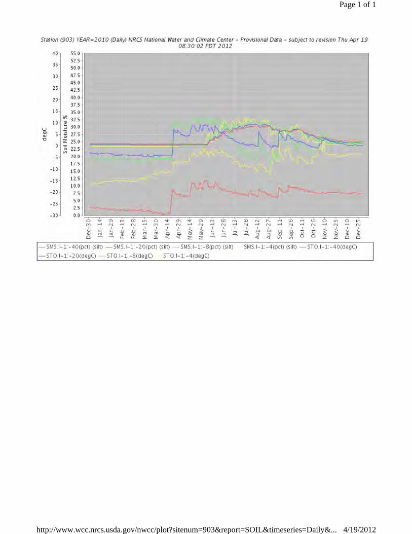
Page 1 of 1
4/19/2012http://www.wcc.nrcs.usda.gov/nwcc/plot?sitenum=903&report=SOIL×eries=Daily&...
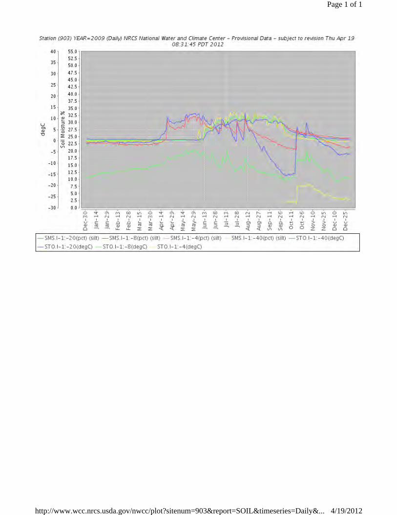
Page 1 of 1
4/19/2012http://www.wcc.nrcs.usda.gov/nwcc/plot?sitenum=903&report=SOIL×eries=Daily&...


Attachment B NRCS Soil Unit Description


15GEE
21UD2
21UD2
15GEE
71GD4
51GE3
399800
399800
400000
400000
400200
400200
400400
400400
400600
400600
400800
400800
401000
401000
401200
401200
401400
401400
5133
800
5133
800
5134
000
5134
000
5134
200
5134
200
5134
400
5134
400
5134
600
5134
600
5134
800
5134
800
5135
000
5135
000
0 1,000 2,000 3,000500Feet
0 200 400 600100Meters
±
46° 21' 41''
112°
16'
45'
'
46° 20' 59''
112°
16'
44'
'
46° 20' 58''
46° 21' 40''11
2° 1
8' 1
5''
112°
18'
16'
'
Map Scale: 1:9,260 if printed on A size (8.5" x 11") sheet.
Soil Map—Deer Lodge National Forest Area, Montana
(Bullion Mine (Basin, MT))
Natural ResourcesNatural ResourcesNatural ResourcesNatural ResourcesConservation ServiceConservation ServiceConservation ServiceConservation Service
Web Soil SurveyNational Cooperative Soil Survey
4/18/2012Page 1 of 3
MAP LEGEND MAP INFORMATION
Area of Interest (AOI)Area of Interest (AOI)
SoilsSoil Map Units
Special Point FeaturesBlowout
Borrow Pit
Clay Spot
Closed Depression
Gravel Pit
Gravelly Spot
Landfill
Lava Flow
Marsh or swamp
Mine or Quarry
Miscellaneous Water
Perennial Water
Rock Outcrop
Saline Spot
Sandy Spot
Severely Eroded Spot
Sinkhole
Slide or Slip
Sodic Spot
Spoil Area
Stony Spot
Very Stony Spot
Wet Spot
Other
Special Line FeaturesGully
Short Steep Slope
Other
Political FeaturesCities
Water FeaturesStreams and Canals
TransportationRails
Interstate Highways
US Routes
Major Roads
Local Roads
Map Scale: 1:9,260 if printed on A size (8.5" × 11") sheet.
The soil surveys that comprise your AOI were mapped at 1:24,000.
Warning: Soil Map may not be valid at this scale.
Enlargement of maps beyond the scale of mapping can causemisunderstanding of the detail of mapping and accuracy of soil lineplacement. The maps do not show the small areas of contrastingsoils that could have been shown at a more detailed scale.
Please rely on the bar scale on each map sheet for accurate mapmeasurements.
Source of Map: Natural Resources Conservation ServiceWeb Soil Survey URL: http://websoilsurvey.nrcs.usda.govCoordinate System: UTM Zone 12N NAD83
This product is generated from the USDA-NRCS certified data as ofthe version date(s) listed below.
Soil Survey Area: Deer Lodge National Forest Area, MontanaSurvey Area Data: Version 11, Jan 5, 2012
Date(s) aerial images were photographed: 8/14/2005
The orthophoto or other base map on which the soil lines werecompiled and digitized probably differs from the backgroundimagery displayed on these maps. As a result, some minor shiftingof map unit boundaries may be evident.
Soil Map–Deer Lodge National Forest Area, Montana(Bullion Mine (Basin, MT))
Natural ResourcesConservation Service
Web Soil SurveyNational Cooperative Soil Survey
4/18/2012Page 2 of 3

Map Unit Legend
Deer Lodge National Forest Area, Montana (MT635)
Map Unit Symbol Map Unit Name Acres in AOI Percent of AOI
15GEE Sig family-Rock outcrop-Roman family,complex, steep glaciated mountain slopesand ridges
257.3 58.7%
21UD2 Garlet-Worock-Waldbillig families, complex,moderately steep young moraines, cool
162.7 37.1%
51GE3 Ovando family-Rubble land-Leighcan family,complex, steep ridges and mountain slopes
4.4 1.0%
71GD4 Blackleed-Ovando-Kurrie families, complex,high relief mountain slopes and ridges
14.1 3.2%
Totals for Area of Interest 438.5 100.0%
Soil Map–Deer Lodge National Forest Area, Montana Bullion Mine (Basin, MT)
Natural ResourcesConservation Service
Web Soil SurveyNational Cooperative Soil Survey
4/18/2012Page 3 of 3


Deer Lodge National Forest Area, Montana
15GEE—Sig family-Rock outcrop-Roman family, complex,steep glaciated mountain slopes and ridges
Map Unit SettingElevation: 7,120 to 10,560 feetMean annual precipitation: 28 to 40 inchesMean annual air temperature: 34 to 37 degrees FFrost-free period: 20 to 40 days
Map Unit CompositionSig and similar soils: 30 percentRoman and similar soils: 25 percentRock outcrop: 25 percentMinor components: 20 percent
Description of Sig
SettingLandform: Ground morainesLandform position (two-dimensional): Shoulder, summitDown-slope shape: ConvexAcross-slope shape: ConvexParent material: Drift over residuum weathered from granite
Properties and qualitiesSlope: 10 to 35 percentDepth to restrictive feature: 10 to 20 inches to lithic bedrockDrainage class: Well drainedCapacity of the most limiting layer to transmit water
(Ksat): Moderately high to high (0.57 to 1.98 in/hr)Depth to water table: More than 80 inchesFrequency of flooding: NoneFrequency of ponding: NoneAvailable water capacity: Very low (about 0.9 inches)
Interpretive groupsLand capability (nonirrigated): 7sOther vegetative classification: whitebark pine-subalpine fir (PK850),
alpine larch-subalpine fir (PK860), whitebark pine (PK870)
Typical profile0 to 1 inches: Slightly decomposed plant material1 to 5 inches: Very stony loam5 to 15 inches: Very cobbly sandy loam15 to 60 inches: Bedrock
Description of Rock Outcrop
Interpretive groupsLand capability (nonirrigated): 8
Map Unit Description: Sig family-Rock outcrop-Roman family, complex, steepglaciated mountain slopes and ridges–Deer Lodge National Forest Area,Montana
Bullion Mine (Basin, MT)
Natural ResourcesConservation Service
Web Soil SurveyNational Cooperative Soil Survey
4/18/2012Page 1 of 3

Description of Roman
SettingLandform: MorainesDown-slope shape: LinearAcross-slope shape: LinearParent material: Volcanic ash over till derived from granite
Properties and qualitiesSlope: 10 to 35 percentDepth to restrictive feature: More than 80 inchesDrainage class: Excessively drainedCapacity of the most limiting layer to transmit water (Ksat): High (1.98
to 5.95 in/hr)Depth to water table: More than 80 inchesFrequency of flooding: NoneFrequency of ponding: NoneAvailable water capacity: Low (about 3.3 inches)
Interpretive groupsLand capability (nonirrigated): 7sOther vegetative classification: subalpine fir/smooth wood-rush
(PK830), whitebark pine-subalpine fir (PK850), alpine larch-subalpine fir (PK860), whitebark pine (PK870)
Typical profile0 to 9 inches: Very bouldery ashy loam9 to 19 inches: Very gravelly sandy loam19 to 60 inches: Very gravelly loamy coarse sand
Minor Components
FinnPercent of map unit: 10 percentLandform: Drainageways, depressionsDown-slope shape: ConcaveAcross-slope shape: ConcaveOther vegetative classification: subalpine fir/bluejoint (PK650)
Bata, very stonyPercent of map unit: 5 percentLandform: Ground morainesLandform position (two-dimensional): Footslope, toeslopeDown-slope shape: LinearAcross-slope shape: LinearOther vegetative classification: subalpine fir/smooth wood-rush
(PK830), whitebark pine-subalpine fir (PK850), alpine larch-subalpine fir (PK860), whitebark pine (PK870)
Jeru, extremely boulderyPercent of map unit: 5 percentLandform: Ground morainesLandform position (two-dimensional): Shoulder, backslopeDown-slope shape: LinearAcross-slope shape: Linear
Map Unit Description: Sig family-Rock outcrop-Roman family, complex, steepglaciated mountain slopes and ridges–Deer Lodge National Forest Area,Montana
Bullion Mine (Basin, MT)
Natural ResourcesConservation Service
Web Soil SurveyNational Cooperative Soil Survey
4/18/2012Page 2 of 3

Other vegetative classification: subalpine fir/smooth wood-rush(PK830), whitebark pine-subalpine fir (PK850), alpine larch-subalpine fir (PK860), whitebark pine (PK870)
Data Source Information
Soil Survey Area: Deer Lodge National Forest Area, MontanaSurvey Area Data: Version 11, Jan 5, 2012
Map Unit Description: Sig family-Rock outcrop-Roman family, complex, steepglaciated mountain slopes and ridges–Deer Lodge National Forest Area,Montana
Bullion Mine (Basin, MT)
Natural ResourcesConservation Service
Web Soil SurveyNational Cooperative Soil Survey
4/18/2012Page 3 of 3

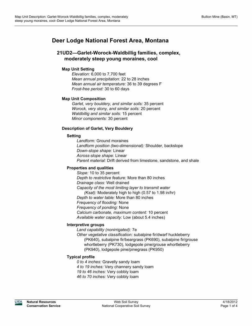
Deer Lodge National Forest Area, Montana
21UD2—Garlet-Worock-Waldbillig families, complex,moderately steep young moraines, cool
Map Unit SettingElevation: 6,000 to 7,700 feetMean annual precipitation: 22 to 28 inchesMean annual air temperature: 36 to 39 degrees FFrost-free period: 30 to 60 days
Map Unit CompositionGarlet, very bouldery, and similar soils: 35 percentWorock, very stony, and similar soils: 20 percentWaldbillig and similar soils: 15 percentMinor components: 30 percent
Description of Garlet, Very Bouldery
SettingLandform: Ground morainesLandform position (two-dimensional): Shoulder, backslopeDown-slope shape: LinearAcross-slope shape: LinearParent material: Drift derived from limestone, sandstone, and shale
Properties and qualitiesSlope: 10 to 35 percentDepth to restrictive feature: More than 80 inchesDrainage class: Well drainedCapacity of the most limiting layer to transmit water
(Ksat): Moderately high to high (0.57 to 1.98 in/hr)Depth to water table: More than 80 inchesFrequency of flooding: NoneFrequency of ponding: NoneCalcium carbonate, maximum content: 10 percentAvailable water capacity: Low (about 5.4 inches)
Interpretive groupsLand capability (nonirrigated): 7eOther vegetative classification: subalpine fir/dwarf huckleberry
(PK640), subalpine fir/beargrass (PK690), subalpine fir/grousewhortleberry (PK730), lodgepole pine/grouse whortleberry(PK940), lodgepole pine/pinegrass (PK950)
Typical profile0 to 4 inches: Gravelly sandy loam4 to 19 inches: Very channery sandy loam19 to 46 inches: Very cobbly loam46 to 70 inches: Very cobbly loam
Map Unit Description: Garlet-Worock-Waldbillig families, complex, moderatelysteep young moraines, cool–Deer Lodge National Forest Area, Montana
Bullion Mine (Basin, MT)
Natural ResourcesConservation Service
Web Soil SurveyNational Cooperative Soil Survey
4/18/2012Page 1 of 4

Description of Worock, Very Stony
SettingLandform: Ground morainesLandform position (two-dimensional): Toeslope, footslopeDown-slope shape: LinearAcross-slope shape: LinearParent material: Drift derived from sandstone and shale
Properties and qualitiesSlope: 10 to 35 percentDepth to restrictive feature: More than 80 inchesDrainage class: Well drainedCapacity of the most limiting layer to transmit water
(Ksat): Moderately high (0.20 to 0.57 in/hr)Depth to water table: More than 80 inchesFrequency of flooding: NoneFrequency of ponding: NoneAvailable water capacity: Moderate (about 6.1 inches)
Interpretive groupsLand capability (nonirrigated): 7eOther vegetative classification: subalpine fir/dwarf huckleberry
(PK640), subalpine fir/beargrass (PK690), subalpine fir/grousewhortleberry (PK730), lodgepole pine/grouse whortleberry(PK940), lodgepole pine/pinegrass (PK950)
Typical profile0 to 1 inches: Slightly decomposed plant material1 to 19 inches: Stony loam19 to 53 inches: Very gravelly clay loam53 to 60 inches: Very gravelly clay loam
Description of Waldbillig
SettingLandform: Ground morainesLandform position (two-dimensional): Footslope, toeslopeDown-slope shape: LinearAcross-slope shape: LinearParent material: Volcanic ash over drift derived from sandstone and
siltstone
Properties and qualitiesSlope: 10 to 35 percentDepth to restrictive feature: More than 80 inchesDrainage class: Well drainedCapacity of the most limiting layer to transmit water
(Ksat): Moderately high to high (0.57 to 1.98 in/hr)Depth to water table: More than 80 inchesFrequency of flooding: NoneFrequency of ponding: NoneAvailable water capacity: Low (about 5.8 inches)
Map Unit Description: Garlet-Worock-Waldbillig families, complex, moderatelysteep young moraines, cool–Deer Lodge National Forest Area, Montana
Bullion Mine (Basin, MT)
Natural ResourcesConservation Service
Web Soil SurveyNational Cooperative Soil Survey
4/18/2012Page 2 of 4

Interpretive groupsLand capability (nonirrigated): 6eOther vegetative classification: subalpine fir/dwarf huckleberry
(PK640), subalpine fir/beargrass (PK690), subalpine fir/grousewhortleberry (PK730), lodgepole pine/grouse whortleberry(PK940), lodgepole pine/pinegrass (PK950)
Typical profile0 to 2 inches: Moderately decomposed plant material2 to 12 inches: Gravelly ashy silt loam12 to 28 inches: Very gravelly fine sandy loam28 to 60 inches: Very gravelly sandy loam
Minor Components
Bata, stonyPercent of map unit: 10 percentLandform: Ground morainesLandform position (two-dimensional): Toeslope, footslopeDown-slope shape: LinearAcross-slope shape: LinearOther vegetative classification: subalpine fir/dwarf huckleberry
(PK640), subalpine fir/beargrass (PK690), subalpine fir/grousewhortleberry (PK730), lodgepole pine/grouse whortleberry(PK940), lodgepole pine/pinegrass (PK950)
Elvick, very stonyPercent of map unit: 10 percentLandform: Drainageways, ground moraines, depressionsLandform position (two-dimensional): ToeslopeDown-slope shape: LinearAcross-slope shape: ConcaveOther vegetative classification: subalpine fir/queencup beadlily
(PK620)
LowderPercent of map unit: 5 percentLandform: Drainageways, depressionsDown-slope shape: ConcaveAcross-slope shape: ConcaveOther vegetative classification: subalpine fir/bluejoint (PK650)
LobergPercent of map unit: 5 percentLandform: Ground morainesLandform position (two-dimensional): Toeslope, footslopeDown-slope shape: LinearAcross-slope shape: LinearOther vegetative classification: subalpine fir/dwarf huckleberry
(PK640), subalpine fir/beargrass (PK690), subalpine fir/grouse
Map Unit Description: Garlet-Worock-Waldbillig families, complex, moderatelysteep young moraines, cool–Deer Lodge National Forest Area, Montana
Bullion Mine (Basin, MT)
Natural ResourcesConservation Service
Web Soil SurveyNational Cooperative Soil Survey
4/18/2012Page 3 of 4

whortleberry (PK730), lodgepole pine/grouse whortleberry(PK940), lodgepole pine/pinegrass (PK950)
Data Source Information
Soil Survey Area: Deer Lodge National Forest Area, MontanaSurvey Area Data: Version 11, Jan 5, 2012
Map Unit Description: Garlet-Worock-Waldbillig families, complex, moderatelysteep young moraines, cool–Deer Lodge National Forest Area, Montana
Bullion Mine (Basin, MT)
Natural ResourcesConservation Service
Web Soil SurveyNational Cooperative Soil Survey
4/18/2012Page 4 of 4

Deer Lodge National Forest Area, Montana
51GE3—Ovando family-Rubble land-Leighcan family,complex, steep ridges and mountain slopes
Map Unit SettingElevation: 7,700 to 10,560 feetMean annual precipitation: 28 to 40 inchesMean annual air temperature: 34 to 37 degrees FFrost-free period: 20 to 40 days
Map Unit CompositionOvando and similar soils: 30 percentRubble land: 25 percentLeighcan, very stony, and similar soils: 20 percentHun and similar soils: 15 percentMinor components: 10 percent
Description of Ovando
SettingLandform: Ridges, mountain slopesLandform position (two-dimensional): Shoulder, summitDown-slope shape: LinearAcross-slope shape: LinearParent material: Colluvium derived from granite
Properties and qualitiesSlope: 25 to 50 percentDepth to restrictive feature: More than 80 inchesDrainage class: Excessively drainedCapacity of the most limiting layer to transmit water (Ksat): High (1.98
to 5.95 in/hr)Depth to water table: More than 80 inchesFrequency of flooding: NoneFrequency of ponding: NoneAvailable water capacity: Very low (about 2.6 inches)
Interpretive groupsLand capability (nonirrigated): 7sOther vegetative classification: subalpine fir/smooth wood-rush
(PK830), whitebark pine-subalpine fir (PK850), alpine larch-subalpine fir (PK860), whitebark pine (PK870)
Typical profile0 to 5 inches: Very bouldery sandy loam5 to 20 inches: Very gravelly sandy loam20 to 60 inches: Very cobbly loamy sand
Description of Leighcan, Very Stony
SettingLandform: Ridges, mountain slopes, patterned groundLandform position (two-dimensional): Shoulder, summit
Map Unit Description: Ovando family-Rubble land-Leighcan family, complex,steep ridges and mountain slopes–Deer Lodge National Forest Area, Montana
Bullion Mine (Basin, MT)
Natural ResourcesConservation Service
Web Soil SurveyNational Cooperative Soil Survey
4/18/2012Page 1 of 3

Down-slope shape: LinearAcross-slope shape: LinearParent material: Colluvium derived from granite
Properties and qualitiesSlope: 25 to 50 percentDepth to restrictive feature: More than 80 inchesDrainage class: Well drainedCapacity of the most limiting layer to transmit water (Ksat): High (1.98
to 5.95 in/hr)Depth to water table: More than 80 inchesFrequency of flooding: NoneFrequency of ponding: NoneAvailable water capacity: Very low (about 2.8 inches)
Interpretive groupsLand capability (nonirrigated): 7eOther vegetative classification: whitebark pine-subalpine fir (PK850),
alpine larch-subalpine fir (PK860), whitebark pine (PK870),subalpine fir/smooth wood-rush (PK830)
Typical profile0 to 4 inches: Gravelly sandy loam4 to 9 inches: Very gravelly sandy loam9 to 60 inches: Extremely gravelly sandy loam
Description of Hun
SettingLandform: Mountain slopes, ridgesLandform position (two-dimensional): Shoulder, summitDown-slope shape: LinearAcross-slope shape: LinearParent material: Volcanic ash over colluvium derived from granite
Properties and qualitiesSlope: 25 to 50 percentDepth to restrictive feature: More than 80 inchesDrainage class: Well drainedCapacity of the most limiting layer to transmit water (Ksat): High (1.98
to 5.95 in/hr)Depth to water table: More than 80 inchesFrequency of flooding: NoneFrequency of ponding: NoneAvailable water capacity: Low (about 3.9 inches)
Interpretive groupsLand capability (nonirrigated): 7eOther vegetative classification: subalpine fir/smooth wood-rush
(PK830), whitebark pine-subalpine fir (PK850), alpine larch-subalpine fir (PK860), whitebark pine (PK870)
Typical profile0 to 2 inches: Slightly decomposed plant material2 to 5 inches: Moderately decomposed plant material5 to 14 inches: Stony ashy very fine sandy loam
Map Unit Description: Ovando family-Rubble land-Leighcan family, complex,steep ridges and mountain slopes–Deer Lodge National Forest Area, Montana
Bullion Mine (Basin, MT)
Natural ResourcesConservation Service
Web Soil SurveyNational Cooperative Soil Survey
4/18/2012Page 2 of 3

14 to 32 inches: Very gravelly sandy loam32 to 60 inches: Extremely cobbly coarse sand
Minor Components
Rock outcropPercent of map unit: 10 percent
Data Source Information
Soil Survey Area: Deer Lodge National Forest Area, MontanaSurvey Area Data: Version 11, Jan 5, 2012
Map Unit Description: Ovando family-Rubble land-Leighcan family, complex,steep ridges and mountain slopes–Deer Lodge National Forest Area, Montana
Bullion Mine (Basin, MT)
Natural ResourcesConservation Service
Web Soil SurveyNational Cooperative Soil Survey
4/18/2012Page 3 of 3


Deer Lodge National Forest Area, Montana
71GD4—Blackleed-Ovando-Kurrie families, complex, highrelief mountain slopes and ridges
Map Unit SettingElevation: 6,000 to 7,700 feetMean annual precipitation: 22 to 28 inchesMean annual air temperature: 36 to 39 degrees FFrost-free period: 30 to 60 days
Map Unit CompositionBlackleed, very stony, and similar soils: 40 percentOvando, extremely bouldery, and similar soils: 35 percentKurrie and similar soils: 15 percentMinor components: 10 percent
Description of Blackleed, Very Stony
SettingLandform: Mountain slopesDown-slope shape: LinearAcross-slope shape: LinearParent material: Colluvium over residuum weathered from granite
Properties and qualitiesSlope: 45 to 70 percentDepth to restrictive feature: 20 to 40 inches to lithic bedrockDrainage class: Somewhat excessively drainedCapacity of the most limiting layer to transmit water (Ksat): High (1.98
to 5.95 in/hr)Depth to water table: More than 80 inchesFrequency of flooding: NoneFrequency of ponding: NoneAvailable water capacity: Very low (about 2.0 inches)
Interpretive groupsLand capability (nonirrigated): 7eOther vegetative classification: subalpine fir/dwarf huckleberry
(PK640), subalpine fir/beargrass (PK690), subalpine fir/grousewhortleberry (PK730), lodgepole pine/grouse whortleberry(PK940), lodgepole pine/pinegrass (PK950)
Typical profile0 to 3 inches: Cobbly coarse sandy loam3 to 8 inches: Very cobbly coarse sandy loam8 to 27 inches: Very stony coarse sandy loam27 to 60 inches: Bedrock
Description of Ovando, Extremely Bouldery
SettingLandform: Mountain slopesDown-slope shape: Linear
Map Unit Description: Blackleed-Ovando-Kurrie families, complex, high reliefmountain slopes and ridges–Deer Lodge National Forest Area, Montana
Bullion Mine (Basin, MT)
Natural ResourcesConservation Service
Web Soil SurveyNational Cooperative Soil Survey
4/18/2012Page 1 of 3

Across-slope shape: LinearParent material: Colluvium derived from granite
Properties and qualitiesSlope: 45 to 70 percentDepth to restrictive feature: More than 80 inchesDrainage class: Excessively drainedCapacity of the most limiting layer to transmit water (Ksat): High (1.98
to 5.95 in/hr)Depth to water table: More than 80 inchesFrequency of flooding: NoneFrequency of ponding: NoneAvailable water capacity: Very low (about 2.0 inches)
Interpretive groupsLand capability (nonirrigated): 7eOther vegetative classification: subalpine fir/dwarf huckleberry
(PK640), subalpine fir/beargrass (PK690), subalpine fir/grousewhortleberry (PK730), lodgepole pine/grouse whortleberry(PK940), lodgepole pine/pinegrass (PK950)
Typical profile0 to 1 inches: Slightly decomposed plant material1 to 6 inches: Very stony sandy loam6 to 17 inches: Very stony loamy coarse sand17 to 35 inches: Very stony loamy sand35 to 60 inches: Extremely stony loamy sand
Description of Kurrie
SettingLandform: Mountain slopesDown-slope shape: LinearAcross-slope shape: LinearParent material: Colluvium derived from granite
Properties and qualitiesSlope: 45 to 70 percentDepth to restrictive feature: 40 to 60 inches to paralithic bedrockDrainage class: Well drainedCapacity of the most limiting layer to transmit water
(Ksat): Moderately high to high (0.57 to 1.98 in/hr)Depth to water table: More than 80 inchesFrequency of flooding: NoneFrequency of ponding: NoneAvailable water capacity: Low (about 3.9 inches)
Interpretive groupsLand capability (nonirrigated): 7eOther vegetative classification: subalpine fir/dwarf huckleberry
(PK640), subalpine fir/beargrass (PK690), subalpine fir/grousewhortleberry (PK730), lodgepole pine/grouse whortleberry(PK940), lodgepole pine/pinegrass (PK950)
Typical profile0 to 4 inches: Coarse sandy loam
Map Unit Description: Blackleed-Ovando-Kurrie families, complex, high reliefmountain slopes and ridges–Deer Lodge National Forest Area, Montana
Bullion Mine (Basin, MT)
Natural ResourcesConservation Service
Web Soil SurveyNational Cooperative Soil Survey
4/18/2012Page 2 of 3

4 to 23 inches: Very cobbly sandy loam23 to 41 inches: Very cobbly sandy clay loam41 to 46 inches: Very gravelly sandy loam46 to 60 inches: Bedrock
Minor Components
ElvickPercent of map unit: 10 percentLandform: Drainageways, drawsDown-slope shape: LinearAcross-slope shape: ConcaveOther vegetative classification: subalpine fir/queencup beadlily
(PK620)
Data Source Information
Soil Survey Area: Deer Lodge National Forest Area, MontanaSurvey Area Data: Version 11, Jan 5, 2012
Map Unit Description: Blackleed-Ovando-Kurrie families, complex, high reliefmountain slopes and ridges–Deer Lodge National Forest Area, Montana
Bullion Mine (Basin, MT)
Natural ResourcesConservation Service
Web Soil SurveyNational Cooperative Soil Survey
4/18/2012Page 3 of 3


Attachment C ET Water Budget Calculations


Irrigation Water BudgetScenario: Native Grasses - Minimal Recharge
MonthETo (in) Kc
P (in) ETc (in)
Peff (in)
NIWR(in)
GIWR w/o LF
(in)
GIWR w/ LF (in)
Total Recharge
(in)Jan 0.60 0.00 2.20 0.00 0.00 0.00 0.00 0.00 0.00Feb 0.80 0.00 1.90 0.00 0.00 0.00 0.00 0.00 0.00Mar 1.50 0.00 2.30 0.00 0.00 0.00 0.00 0.00 0.00Apr 2.30 0.00 3.20 0.00 0.00 0.00 0.00 0.00 0.00May 3.30 0.00 3.50 0.00 0.00 0.00 0.00 0.00 0.00Jun 4.10 0.00 4.20 0.00 0.00 0.00 0.00 0.00 0.00Jul 5.00 0.71 2.70 3.55 1.52 2.03 2.54 2.54 0.51Aug 4.30 0.71 1.70 3.05 0.97 2.08 2.60 2.60 0.52Sep 2.70 0.71 2.00 1.92 1.06 0.86 1.08 1.08 0.22Oct 1.50 0.00 1.00 0.00 0.00 0.00 0.00 0.00 0.00Nov 0.70 0.00 2.10 0.00 0.00 0.00 0.00 0.00 0.00Dec 0.50 0.00 2.30 0.00 0.00 0.00 0.00 0.00 0.00Total 27.30 29.10 8.52 3.54 4.98 6.22 6.22 1.24
Vegetation Type
Irrigated Area
(acres) Annual Irrigation Demand12.0 6.2 ac-ft
2.0 MGNormal Depth of Soil Moisture Depletion (in) 1.34
LF 0% Irrigation Season RechargeTotal Leaching Requirement (in) 0.00 1.2 ac-ft
Combined Irrigation Efficiency 80% 0.4 MG
Grasses @ 50% Cover
Notes and Definitions:Kc - crop coefficientETo - reference grass evapotranspirationETc - crop evapotranspiration (ETo x [(Kc turf x turf fraction) + (Kc shrub x shrub fraction)] )P - average precipitationPeff - effective precipitation (calculated using SCS method w/ monthly P, ETc, and effective soil water storage)NIWR - net irrigation water requirements (ETc - Peff)GIWR w/o LF - gross irrigation water requirements without leaching fraction (NIWR / (combined irrigation efficiency) )LF - leaching fraction (fraction of total applied water intended for leaching above incidental loss due to non-uniformity)Total Leaching Requirement = GIWR w/ LF - GIWR w/o LFGIWR w/ LF = GIWR w/o LF / (1 - LF)

Irrigation Water BudgetScenario: Lodgepole Pine Forest - Minimal Recharge
MonthETo (in) Kc
P (in) ETc (in)
Peff (in)
NIWR(in)
GIWR w/o LF
(in)
GIWR w/ LF (in)
Total Recharge
(in)Jan 0.60 0.00 2.20 0.00 0.00 0.00 0.00 0.00 0.00Feb 0.80 0.00 1.90 0.00 0.00 0.00 0.00 0.00 0.00Mar 1.50 0.00 2.30 0.00 0.00 0.00 0.00 0.00 0.00Apr 2.30 0.00 3.20 0.00 0.00 0.00 0.00 0.00 0.00May 3.30 0.00 3.50 0.00 0.00 0.00 0.00 0.00 0.00Jun 4.10 0.00 4.20 0.00 0.00 0.00 0.00 0.00 0.00Jul 5.00 1.00 2.70 5.00 1.64 3.36 4.20 4.20 0.84Aug 4.30 1.00 1.70 4.30 1.04 3.26 4.07 4.07 0.81Sep 2.70 1.00 2.00 2.70 1.10 1.60 2.00 2.00 0.40Oct 1.50 0.00 1.00 0.00 0.00 0.00 0.00 0.00 0.00Nov 0.70 0.00 2.10 0.00 0.00 0.00 0.00 0.00 0.00Dec 0.50 0.00 2.30 0.00 0.00 0.00 0.00 0.00 0.00Total 27.30 29.10 12.00 3.79 8.21 10.27 10.27 2.05
Vegetation Type
Irrigated Area
(acres) Annual Irrigation Demand7.0 6.0 ac-ft
2.0 MGNormal Depth of Soil Moisture Depletion (in) 1.34
LF 0% Irrigation Season RechargeTotal Leaching Requirement (in) 0.00 1.2 ac-ft
Combined Irrigation Efficiency 80% 0.4 MG
Conifer Forest
Notes and Definitions:Kc - crop coefficientETo - reference grass evapotranspirationETc - crop evapotranspiration (ETo x [(Kc turf x turf fraction) + (Kc shrub x shrub fraction)] )P - average precipitationPeff - effective precipitation (calculated using SCS method w/ monthly P, ETc, and effective soil water storage)NIWR - net irrigation water requirements (ETc - Peff)GIWR w/o LF - gross irrigation water requirements without leaching fraction (NIWR / (combined irrigation efficiency) )LF - leaching fraction (fraction of total applied water intended for leaching above incidental loss due to non-uniformity)Total Leaching Requirement = GIWR w/ LF - GIWR w/o LFGIWR w/ LF = GIWR w/o LF / (1 - LF)Normal Depth of Soil Moisture Depletion is often 50% of AWHC over the rooting zone depth

Irrigation Water BudgetScenario: Native Grasses - High Recharge
MonthETo (in) Kc
P (in) ETc (in)
Peff (in)
NIWR(in)
GIWR w/o LF
(in)
GIWR w/ LF (in)
Total Recharge
(in)Jan 0.60 0.00 2.20 0.00 0.00 0.00 0.00 0.00 0.00Feb 0.80 0.00 1.90 0.00 0.00 0.00 0.00 0.00 0.00Mar 1.50 0.00 2.30 0.00 0.00 0.00 0.00 0.00 0.00Apr 2.30 0.00 3.20 0.00 0.00 0.00 0.00 0.00 0.00May 3.30 0.00 3.50 0.00 0.00 0.00 0.00 0.00 0.00Jun 4.10 0.00 4.20 0.00 0.00 0.00 0.00 0.00 0.00Jul 5.00 0.71 2.70 3.55 1.52 2.03 2.54 5.09 3.05Aug 4.30 0.71 1.70 3.05 0.97 2.08 2.60 5.21 3.12Sep 2.70 0.71 2.00 1.92 1.06 0.86 1.08 2.15 1.29Oct 1.50 0.00 1.00 0.00 0.00 0.00 0.00 0.00 0.00Nov 0.70 0.00 2.10 0.00 0.00 0.00 0.00 0.00 0.00Dec 0.50 0.00 2.30 0.00 0.00 0.00 0.00 0.00 0.00Total 27.30 29.10 8.52 3.54 4.98 6.22 12.44 7.47
Vegetation Type
Irrigated Area
(acres) Annual Irrigation Demand6.0 6.2 ac-ft
2.0 MGNormal Depth of Soil Moisture Depletion (in) 1.34
LF 50% Irrigation Season RechargeTotal Leaching Requirement (in) 6.22 3.7 ac-ft
Combined Irrigation Efficiency 80% 1.2 MG
Notes and Definitions:Kc - crop coefficientETo - reference grass evapotranspirationETc - crop evapotranspiration (ETo x [(Kc turf x turf fraction) + (Kc shrub x shrub fraction)] )P - average precipitationPeff - effective precipitation (calculated using SCS method w/ monthly P, ETc, and effective soil water storage)NIWR - net irrigation water requirements (ETc - Peff)GIWR w/o LF - gross irrigation water requirements without leaching fraction (NIWR / (combined irrigation efficiency) )LF - leaching fraction (fraction of total applied water intended for leaching above incidental loss due to non-uniformity)Total Leaching Requirement = GIWR w/ LF - GIWR w/o LFGIWR w/ LF = GIWR w/o LF / (1 - LF)
Grasses @ 50% Cover

Irrigation Water BudgetScenario: Lodgepole Pine Forest - High Recharge
MonthETo (in) Kc
P (in) ETc (in)
Peff (in)
NIWR(in)
GIWR w/o LF
(in)
GIWR w/ LF (in)
Total Recharge
(in)Jan 0.60 0.00 2.20 0.00 0.00 0.00 0.00 0.00 0.00Feb 0.80 0.00 1.90 0.00 0.00 0.00 0.00 0.00 0.00Mar 1.50 0.00 2.30 0.00 0.00 0.00 0.00 0.00 0.00Apr 2.30 0.00 3.20 0.00 0.00 0.00 0.00 0.00 0.00May 3.30 0.00 3.50 0.00 0.00 0.00 0.00 0.00 0.00Jun 4.10 0.00 4.20 0.00 0.00 0.00 0.00 0.00 0.00Jul 5.00 1.00 2.70 5.00 1.64 3.36 4.20 8.39 5.04Aug 4.30 1.00 1.70 4.30 1.04 3.26 4.07 8.15 4.89Sep 2.70 1.00 2.00 2.70 1.10 1.60 2.00 3.99 2.39Oct 1.50 0.00 1.00 0.00 0.00 0.00 0.00 0.00 0.00Nov 0.70 0.00 2.10 0.00 0.00 0.00 0.00 0.00 0.00Dec 0.50 0.00 2.30 0.00 0.00 0.00 0.00 0.00 0.00Total 27.30 29.10 12.00 3.79 8.21 10.27 20.53 12.32
Vegetation Type
Irrigated Area
(acres) Annual Irrigation Demand3.5 6.0 ac-ft
2.0 MGNormal Depth of Soil Moisture Depletion (in) 1.34
LF 50% Irrigation Season RechargeTotal Leaching Requirement (in) 10.27 3.6 ac-ft
Combined Irrigation Efficiency 80% 1.2 MG
Notes and Definitions:Kc - crop coefficientETo - reference grass evapotranspirationETc - crop evapotranspiration (ETo x [(Kc turf x turf fraction) + (Kc shrub x shrub fraction)] )P - average precipitationPeff - effective precipitation (calculated using SCS method w/ monthly P, ETc, and effective soil water storage)NIWR - net irrigation water requirements (ETc - Peff)GIWR w/o LF - gross irrigation water requirements without leaching fraction (NIWR / (combined irrigation efficiency) )LF - leaching fraction (fraction of total applied water intended for leaching above incidental loss due to non-uniformity)Total Leaching Requirement = GIWR w/ LF - GIWR w/o LFGIWR w/ LF = GIWR w/o LF / (1 - LF)Normal Depth of Soil Moisture Depletion is often 50% of AWHC over the rooting zone depth
Conifer Forest

Attachment D ROM Cost Estimate

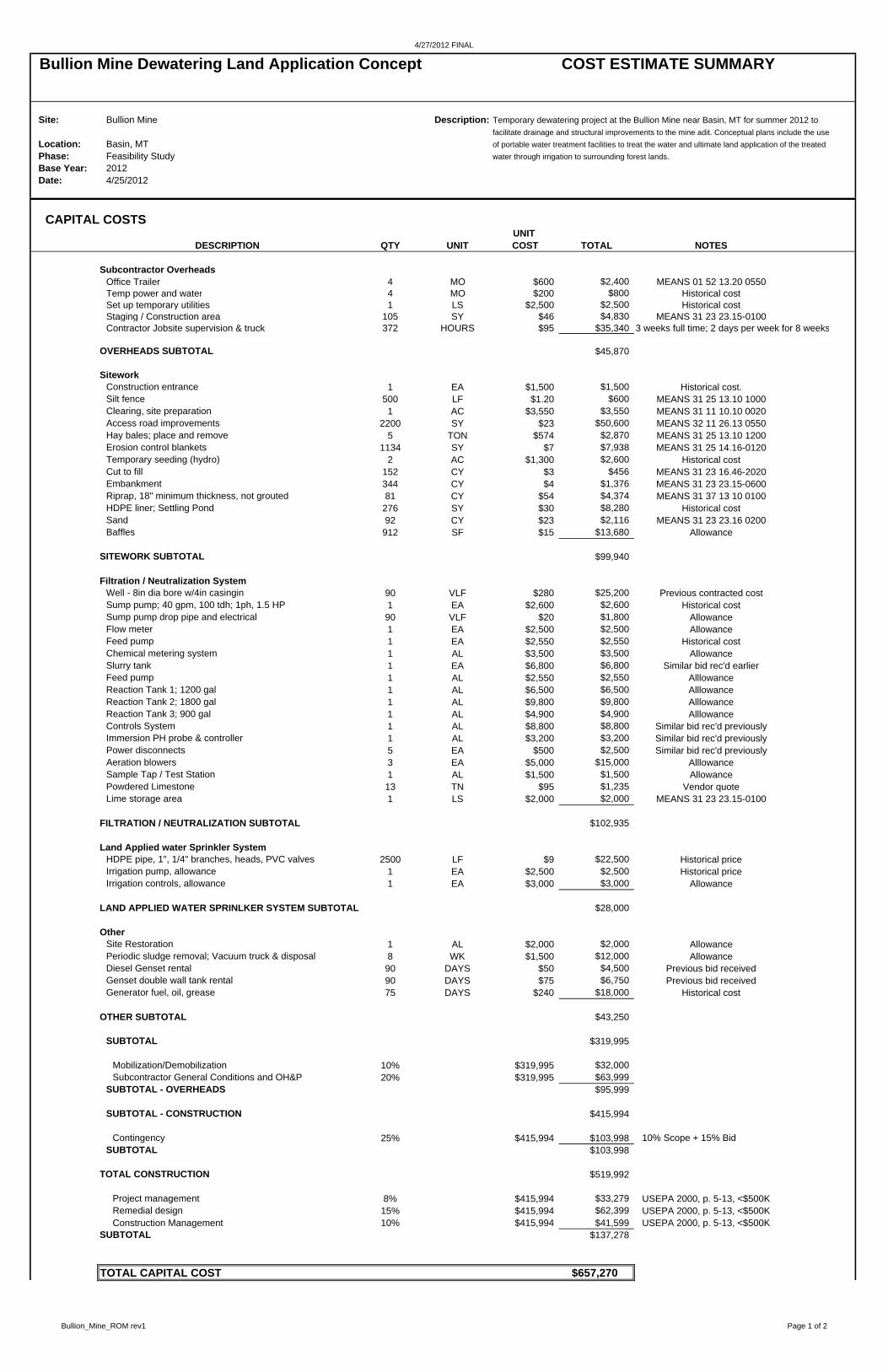
4/27/2012 FINAL
Bullion Mine Dewatering Land Application Concept COST ESTIMATE SUMMARY
Site: Bullion Mine Description: Temporary dewatering project at the Bullion Mine near Basin, MT for summer 2012 to facilitate drainage and structural improvements to the mine adit. Conceptual plans include the use
Location: Basin, MT of portable water treatment facilities to treat the water and ultimate land application of the treated Phase: Feasibility Study water through irrigation to surrounding forest lands.Base Year: 2012Date: 4/25/2012
CAPITAL COSTSUNIT
DESCRIPTION QTY UNIT COST TOTAL NOTES
Subcontractor OverheadsOffice Trailer 4 MO $600 $2,400 MEANS 01 52 13.20 0550Temp power and water 4 MO $200 $800 Historical costSet up temporary utilities 1 LS $2,500 $2,500 Historical costStaging / Construction area 105 SY $46 $4,830 MEANS 31 23 23.15-0100Contractor Jobsite supervision & truck 372 HOURS $95 $35,340 3 weeks full time; 2 days per week for 8 weeks
OVERHEADS SUBTOTAL $45,870
SiteworkConstruction entrance 1 EA $1,500 $1,500 Historical cost.Silt fence 500 LF $1.20 $600 MEANS 31 25 13.10 1000Clearing, site preparation 1 AC $3,550 $3,550 MEANS 31 11 10.10 0020Access road improvements 2200 SY $23 $50,600 MEANS 32 11 26.13 0550Hay bales; place and remove 5 TON $574 $2,870 MEANS 31 25 13.10 1200Erosion control blankets 1134 SY $7 $7,938 MEANS 31 25 14.16-0120Temporary seeding (hydro) 2 AC $1,300 $2,600 Historical costCut to fill 152 CY $3 $456 MEANS 31 23 16.46-2020Embankment 344 CY $4 $1,376 MEANS 31 23 23.15-0600Riprap, 18" minimum thickness, not grouted 81 CY $54 $4,374 MEANS 31 37 13 10 0100HDPE liner; Settling Pond 276 SY $30 $8,280 Historical costSand 92 CY $23 $2,116 MEANS 31 23 23.16 0200Baffles 912 SF $15 $13,680 Allowance
SITEWORK SUBTOTAL $99,940
Filtration / Neutralization SystemWell - 8in dia bore w/4in casingin 90 VLF $280 $25,200 Previous contracted costSump pump; 40 gpm, 100 tdh; 1ph, 1.5 HP 1 EA $2,600 $2,600 Historical costSump pump drop pipe and electrical 90 VLF $20 $1,800 AllowanceFlow meter 1 EA $2,500 $2,500 AllowanceFeed pump 1 EA $2,550 $2,550 Historical costChemical metering system 1 AL $3,500 $3,500 AllowanceSlurry tank 1 EA $6,800 $6,800 Similar bid rec'd earlierFeed pump 1 AL $2,550 $2,550 AlllowanceReaction Tank 1; 1200 gal 1 AL $6,500 $6,500 AlllowanceReaction Tank 2; 1800 gal 1 AL $9,800 $9,800 AlllowanceReaction Tank 3; 900 gal 1 AL $4,900 $4,900 AlllowanceControls System 1 AL $8,800 $8,800 Similar bid rec'd previouslyImmersion PH probe & controller 1 AL $3,200 $3,200 Similar bid rec'd previouslyPower disconnects 5 EA $500 $2,500 Similar bid rec'd previouslyAeration blowers 3 EA $5,000 $15,000 AlllowanceSample Tap / Test Station 1 AL $1,500 $1,500 AllowancePowdered Limestone 13 TN $95 $1,235 Vendor quoteLime storage area 1 LS $2,000 $2,000 MEANS 31 23 23.15-0100
FILTRATION / NEUTRALIZATION SUBTOTAL $102,935
Land Applied water Sprinkler SystemHDPE pipe, 1", 1/4" branches, heads, PVC valves 2500 LF $9 $22,500 Historical priceIrrigation pump, allowance 1 EA $2,500 $2,500 Historical priceIrrigation controls, allowance 1 EA $3,000 $3,000 Allowance
LAND APPLIED WATER SPRINLKER SYSTEM SUBTOTAL $28,000
OtherSite Restoration 1 AL $2,000 $2,000 AllowancePeriodic sludge removal; Vacuum truck & disposal 8 WK $1,500 $12,000 AllowanceDiesel Genset rental 90 DAYS $50 $4,500 Previous bid receivedGenset double wall tank rental 90 DAYS $75 $6,750 Previous bid receivedGenerator fuel, oil, grease 75 DAYS $240 $18,000 Historical cost
OTHER SUBTOTAL $43,250
SUBTOTAL $319,995
Mobilization/Demobilization 10% $319,995 $32,000Subcontractor General Conditions and OH&P 20% $319,995 $63,999
SUBTOTAL - OVERHEADS $95,999
SUBTOTAL - CONSTRUCTION $415,994
Contingency 25% $415,994 $103,998 10% Scope + 15% BidSUBTOTAL $103,998
TOTAL CONSTRUCTION $519,992
Project management 8% $415,994 $33,279 USEPA 2000, p. 5-13, <$500KRemedial design 15% $415,994 $62,399 USEPA 2000, p. 5-13, <$500KConstruction Management 10% $415,994 $41,599 USEPA 2000, p. 5-13, <$500K
SUBTOTAL $137,278
TOTAL CAPITAL COST $657,270
Bullion_Mine_ROM rev1 Page 1 of 2

4/27/2012 FINALBullion Mine Dewatering Land Application Concept COST ESTIMATE SUMMARY
Site: Bullion Mine Description: Temporary dewatering project at the Bullion Mine near Basin, MT for summer 2012 to facilitate drainage and structural improvements to the mine adit. Conceptual plans include the use
Location: Basin, MT of portable water treatment facilities to treat the water and ultimate land application of the treated Phase: Feasibility Study water through irrigation to surrounding forest lands.Base Year: 2012Date: 4/25/2012
OPERATIONS AND MAINTENANCE COSTUNIT
DESCRIPTION QTY UNIT COST TOTAL NOTESO&M LUC
Labor - E-6 1,260 HR $155 $195,300 CH2M Est.Labor - E-1 1,260 HR $62 $78,120 CH2M Est.Mileage 7,200 MI $0.56 $4,032 CH2M Est.; assume 30 mi RTLodging 240 NT $89 $21,360 CH2M HILL AllowancePer diem 240 EA $51 $12,240 CH2M HILL Allowance
0 HR $90 $0 CH2M Est.SUBTOTAL $311,052
Compliance Monitoring and Health & Safety - Ask Dennis about ComplianceAir Monitoring 0 LS $0.00 $0 Groundwater/Surface Water Monitoring 0 LS $0.00 $0 CCI Historical Lab Analysis 8 WK $400.00 $3,200 CCI HistoricalData Validation 8 HR $100.00 $800 CCI HistoricalReports 8 EA $2,500.00 $20,000 CCI HistoricalMisc 0 LS $500.00 $0 CCI Historical
SUBTOTAL $24,000SUBTOTAL - ALL TASKS - O & M $335,052
Mobilization/Demobilization 5% $16,753 General Conditions 25% $83,763
SUBTOTAL $435,568Contingency 25% $108,892 10% Scope + 15% Bid, USEPA 2000, p.5-10 & 5-11
SUBTOTAL $544,460
Escalation to Mid-Pt 0% $0Project Management 10% $54,446 USEPA 2000, p. 5-13, <$100KRemedial Design 0% $0 USEPA 2000, p. 5-13, <$100KConstruction Management 0% $0 USEPA 2000, p. 5-13, <$100K
SUBTOTAL $598,905
Taxes0.00% $598,905 $0
0% $0 $0SUBTOTAL $0
TOTAL O&M $598,905
Bullion_Mine_ROM rev1 Page 2 of 2

Appendix D Detailed Cost Estimates


Bullion Mine Site Cost EstimateAlternative 1 - No Action
Capital CostsDescription Quantity Unit Unit Cost Cost Assumptions
Subtotal Capital Costs $0Contingencies (50%) $0
Engineering and SDC (15%) $0Subtotal Capital Costs $0
Operations and MaintenanceDescription Quantity Unit Unit Cost Cost Assumptions
Monitoring 1 LS/YR $10,000 $10,000Monthly sampling of streams and quarterly sampling of monitoring wells
Subtotal O & M Costs $10,000Contingencies (50%) $5,000
Net Present Value of O& M Costs $230,587 Assumes 5% discount rate for 30 years
Alternative 1 Total Present Worth Costs $231,000

Bullion Mine Site Cost EstimateAlternative 2 - Mine Sealing through Re-opened Adit
Capital CostsDescription Quantity Unit Unit Cost Cost Assumptions
Mobilization and Demobilization 1 LS $50,000 $50,000Reopen Mine Tunnels 250 FT $1,248 $311,875 1 adit, 250 feet of tunnel and open cutMine Sealing - Grout Curtain 120 EA $2,910 $349,200 One grout curtain at each end of concrete plugMine Out Plug Area 1 LS $71,200 $71,200 Over excavate each tunnel for plugPlug 1 LS $140,200 $140,200 Bulkheads, concrete and constructionErosion Control Seeding 1 Acres $2,000 $2,000 Reseed contractor staging area6" HDPE Pipe 250 LF $20 $5,000 HDPE pipe running through concrete plugPipe Intake Grating and Valves 1 EA $5,000 $5,000
Monitoring Wells 3 EA $30,000 $90,000One upgradient and two downgradient monitoring wells for grout curtain
Geological Investigations 1 LS $200,000 $200,000 Investigate geologic suitability for mine sealingMobile Water Treatment System 1 LS $1,256,000 $1,256,000 Treat up to 2.5 million gallons
Subtotal Capital Costs $2,480,475Contingencies (50%) $1,240,238 Contingencies at 50% due to uncertainties of mine sealing
Engineering and SDC (15%) $558,107Subtotal Capital Costs $4,279,000
Operations and MaintenanceDescription Quantity Unit Unit Cost Cost Assumptions
Miscellaneous Equipment and Supplies 1 LS/YR $500 $500
Replace Grout Curtains 1 LS/YR $30,000 $30,000Replace grout curtains every ten years--yearly cost is 1/10 of replacement cost
Monitoring 1 LS/YR $20,000 $20,000Monthly sampling of streams and quarterly sampling of monitoring wells
Subtotal O & M Costs $50,500Contingencies (50%) $25,250
Net Present Value of O& M Costs $1,164,463 Assumes 5% discount rate for 30 years
Alternative 2 Total Present Worth Costs $5,443,000

Bullion Mine Site Cost EstimateAlternative 3 - Active Treatment
Capital CostsDescription Quantity Unit Unit Cost Cost Assumptions
Mobilization and Demobilization 1 LS $100,000 $100,000Extend Power 3 Miles $40,000 $100,000 Extend power up Jack Creek RoadSite Preparation and Grading 1,250 SY $2 $2,500 75' x 150'Erosion Control Seeding 1 Acres $2,000 $2,000Reinforced Concrete (slab) 420 CY $455 $191,100 75' x 150' x 12" thickPipe Intake Grating and Valves 1 LS $2,500 $2,500PVC 6" Solid Pipe 100 LF $15 $1,500 100 ft discharge pipe to Jill CreekTreatment Plant Structure 1 LS $1,000,000 $1,000,000 Construction of 30 GPM HDS treatment plantMobile Water Treatment System 1 LS $1,256,000 $1,256,000 Mine De-watering up to 2.5 M gallonsAdit Discharge Collection 1 LS $97,000 $97,000 Collect Mine discharge in portal areaGroundwater Cutoff Trench 1 LS $31,000 $31,000 Downgradient french drain to collect shallow GW
Subtotal Capital Costs $2,783,600Contingencies (35%) $974,260
Engineering and SDC (15%) $563,679Subtotal Capital Costs $4,322,000
Operations and MaintenanceDescription Quantity Unit Unit Cost Cost Assumptions
Labor (Operators) 1,230 HR/YR $50 $61,500 Assume 1/2 time operation, plus 120 hrs misc O&M/yr
Chemicals (lime) 11 TONS/YR $120 $1,26070% of Crystal Mine based on design flow. Assume lime supply from limestone quarry near Helena, MT
Power Costs 63,700 KwH/YR $0.09 $5,733 70% of Crystal Mine based on design flow.Miscellaneous Equipment and Supplies 1 LS/YR $9,000 $9,000Equipment Replacement Fund 1 LS/YR $20,000 $20,000 Replace elect and mechanical equip every 15 years
Sludge disposal 700 CY/YR $10 $7,00070% of Crystal Mine based on design flow.Dewatered, hauled 10 miles one way to Luttrell Repository
Monitoring 1 LS/YR $28,000 $28,000Monthly sampling of streams and weekly sampling of processes
Subtotal O & M Costs $132,493Contingencies (35%) $46,373
Net Present Value of O& M Costs $2,749,602 Assumes 5% discount rate for 30 years
Alternative 3 Total Present Worth Costs $7,072,000

Bullion Mine Site Cost EstimateAlternative 4 - Semi-Active Treatment
Capital CostsDescription Quantity Unit Unit Cost Cost Assumptions
Mobilization and Demobilization 1 LS $100,000 $100,000Excavation 950 CY $10 $9,500Backfill 950 CY $10 $9,500Conveyance Ditches 50 CY $50 $2,500 320 ft long, 2 ft wide, 2 ft deepAdit Collection 1 EA $0Liner Protection Gravel 460 CY $30 $13,800 12" on top of liner and 6" below linerRip Rap 30 CY $40 $1,200Erosion Control Seeding 2 Acres $2,000 $4,000Reinforced Concrete (slab) 10 CY $455 $4,550 16 ft x 16 ft by 12 in thick6" HDPE Pipe 110 LF $20 $2,200Pipe Intake Grating and Valves 1 LS $2,500 $2,500PVC 6" Solid Pipe 450 LF $15 $6,750HDPE Liner 11,100 SF $1 $11,100 4400 sq ft for pond 1 & 2, 2373 for pond 3PVC Liner 1,280 SF $0.75 $960 320' x 4' wide for "V" ditchTreatment Plant Structure 1 LS $200,000 $200,000 Estimate from AquafixOutlet Structure 3 LS $5,000 $15,000Mobile Water Treatment System 1 LS $1,256,000 $1,256,000 Mine De-watering up to 2.5 M gallonsAdit Discharge Collection 1 LS $97,000 $97,000 Collect Mine discharge in portal areaGroundwater Cutoff Trench 1 LS $31,000 $31,000 Downgradient french drain to collect shallow GW
Subtotal Capital Costs $1,767,560Contingencies (35%) $618,646
Engineering and SDC (15%) $357,931Subtotal Capital Costs $2,744,000
Operations and MaintenanceDescription Quantity Unit Unit Cost Cost Assumptions
Labor (Operators) 400 HR/YR $50 $20,000 Assume 6 hrs/wk, plus 88 hrs/yr for misc O&M
Chemicals 11 TONS/YR $120 $1,26070% of Crystal Mine based on design flow.Assume lime supply from limestone quarry near Helena, MT
Miscellaneous Equipment and Supplies 1 LS/YR $4,500 $4,500Equipment Replacement Fund 1 LS/YR $6,700 $6,700 Replace lime feed equipment every 15 years
Sludge disposal 1,400 CY/YR $10 $14,000Based on operating experience from Aquafix pilot study and 70% of design flow at Crystal Mine.
Monitoring 1 LS/YR $28,000 $28,000Monthly sampling of streams and weekly sampling of processes
Subtotal O & M Costs $74,460Contingencies (35%) $26,061
Net Present Value of O& M Costs $1,545,254 Assumes 5% discount rate for 30 years
Alternative 4 Total Present Worth Costs $4,289,000

Bullion Mine Site Cost EstimateAlternative 5 - Semi-Passive Treatment
Capital CostsDescription Quantity Unit Unit Cost Cost Assumptions
Mobilization and Demobilization 1 LS $50,000 $50,000Excavation 4,426 CY $10 $44,260Backfill 4,426 CY $10 $44,260Liner Protection Gravel 550 CY $30 $16,500 12" on top of liner and 6" below linerDrain Rock 380 CY $40 $15,200Limestone Gravel 320 CY $80 $25,600 Assume supply from limestone quarry near Helena, MTLimestone Sand 120 CY $80 $9,600 Assume supply from limestone quarry near Helena, MTCompost 3,560 CY $20 $71,200Erosion Control Seeding 2 Acres $2,000 $4,0006" HDPE Pipe 110 LF $20 $2,200Pipe Intake Grating and Valves 1 LS $2,500 $2,500PVC 6" Solid Pipe 670 LF $15 $10,050PVC 6" Perforated Pipe 690 LF $15 $10,350HDPE Liner 14,781 SF $1 $7,391 For polishing pondPVC Liner 56,000 SF $0.75 $42,000 Wrap individual SRBR cells in PVC linerGeotextile Fabric 7,296 SF $0.30 $2,189Outlet Structure 1 EA $5,000 $5,000Weir Box 3 EA $3,000 $9,000Mobile Water Treatment System 1 EA $1,256,000 $1,256,000 Mine De-watering up to 2.5 M gallonsAdit Discharge Collection 1 LS $97,000 $97,000 Collect Mine discharge in portal areaGroundwater Cutoff Trench 1 LS $31,000 $31,000 Downgradient french drain to collect shallow GW
Subtotal Capital Costs $1,755,299Contingencies (35%) $614,355
Engineering and SDC (15%) $355,448Subtotal Capital Costs $2,725,000
Operations and MaintenanceDescription Quantity Unit Unit Cost Cost Assumptions
Labor (Operators) 100 HR/YR $50 $5,000 Assume 6 hrs/mo plus 28 hrs/yr for misc O&MRototilling of pH Adjustment Cell 1 LS/YR $250 $250 Assume $500 every two years
Periodic Replacement of pH Adjustment Cell 1 LS/YR $5,500 $5,500 Assume $33,000 to replace media every 6 yrs
Periodic Replacement of SRBR Beds 1 LS/YR $13,000 $13,000 Assume $200,000 to reconstruct SRBR cells every 15 yrsMiscellaneous Equipment and Supplies 1 LS/YR $4,500 $4,500
Sludge disposal 350 CY/YR $10 $3,500Disposal of pH adjustment (1/6 per year) and SRBR (1/15 per year) media at Luttrell Repository
Monitoring 1 LS/YR $19,000 Monthly sampling of streams and processesSubtotal O & M Costs $50,750Contingencies (35%) $17,763
Net Present Value of O& M Costs $1,053,205 Assumes 5% discount rate for 30 years
Alternative 5 Total Present Worth Costs $3,778,000
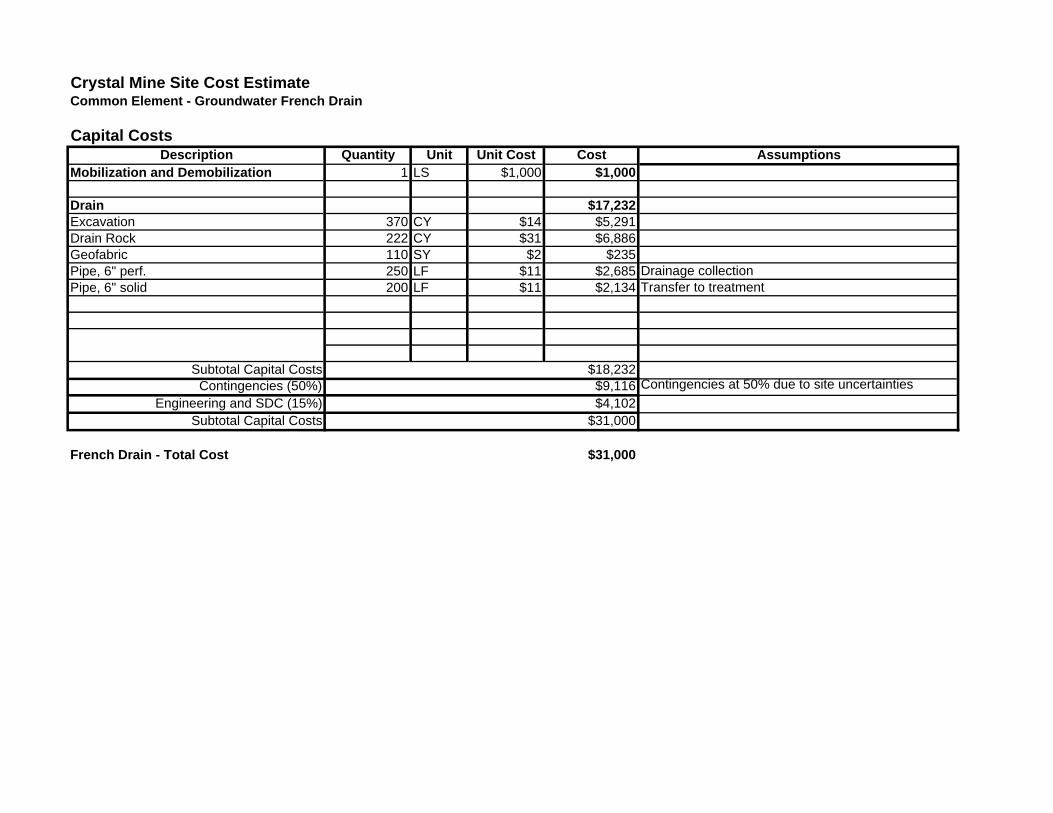
Crystal Mine Site Cost EstimateCommon Element - Groundwater French Drain
Capital CostsDescription Quantity Unit Unit Cost Cost Assumptions
Mobilization and Demobilization 1 LS $1,000 $1,000
Drain $17,232Excavation 370 CY $14 $5,291Drain Rock 222 CY $31 $6,886Geofabric 110 SY $2 $235Pipe, 6" perf. 250 LF $11 $2,685 Drainage collectionPipe, 6" solid 200 LF $11 $2,134 Transfer to treatment
Subtotal Capital Costs $18,232Contingencies (50%) $9,116 Contingencies at 50% due to site uncertainties
Engineering and SDC (15%) $4,102Subtotal Capital Costs $31,000
French Drain - Total Cost $31,000
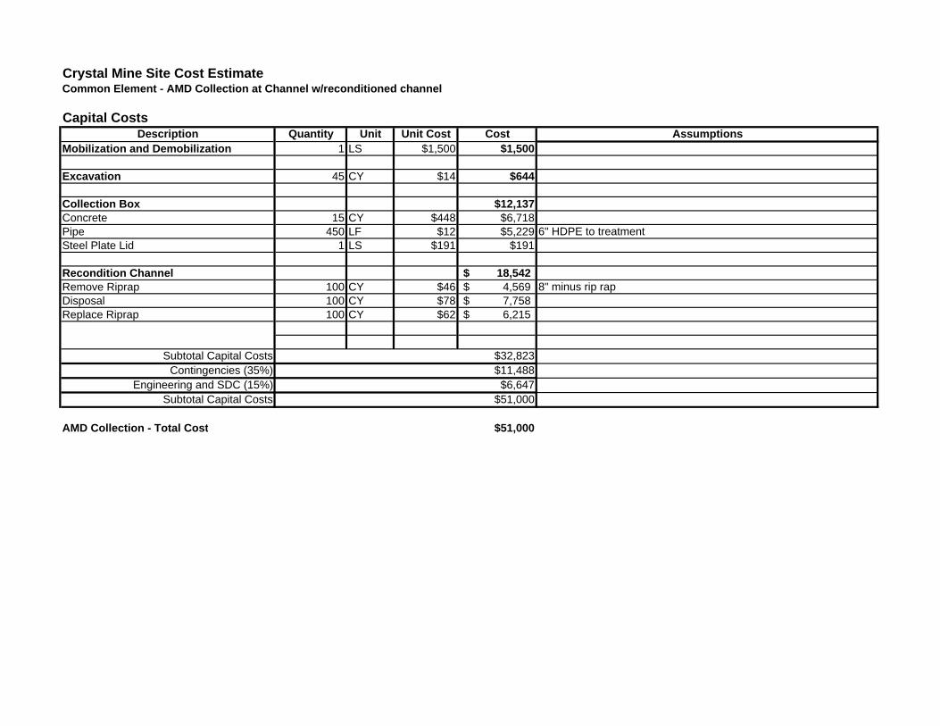
Crystal Mine Site Cost EstimateCommon Element - AMD Collection at Channel w/reconditioned channel
Capital CostsDescription Quantity Unit Unit Cost Cost Assumptions
Mobilization and Demobilization 1 LS $1,500 $1,500
Excavation 45 CY $14 $644
Collection Box $12,137Concrete 15 CY $448 $6,718Pipe 450 LF $12 $5,229 6" HDPE to treatmentSteel Plate Lid 1 LS $191 $191
Recondition Channel 18,542$ Remove Riprap 100 CY $46 4,569$ 8" minus rip rapDisposal 100 CY $78 7,758$ Replace Riprap 100 CY $62 6,215$
Subtotal Capital Costs $32,823Contingencies (35%) $11,488
Engineering and SDC (15%) $6,647Subtotal Capital Costs $51,000
AMD Collection - Total Cost $51,000

Crystal Mine Site Cost EstimateCommon Element - AMD Collection
Capital CostsDescription Quantity Unit Unit Cost Cost Assumptions
Mobilization and Demobilization 1 LS $2,500 $2,500
Adit Discharge Channel Reuse $26,015Riprap Removal 100 CY $46 $4,569 1 1/2 depth in channelDisposal 100 CY $78 $7,758 At Luttrell Bedding Material 20 CY $27 $544Pipe 1,100 LF $12 $12,782 6" HDPE Adit to cutoff wall and cutoff wall to treatmentBackfill 35 CY $10 $363
Adit Collection Basin $27,498Concrete Dam 70 CY $366 $25,631 Reinforced Gravity DamLiner 750 SF $2 $1,868 HDPE
Subtotal Capital Costs $56,013Contingencies (50%) $28,007 Allows for uncertainty in dam construction
Engineering and SDC (15%) $12,603Total Capital Costs $97,000
AMD Collection - Total Cost $97,000
