fo,, - waco, texas
TRANSCRIPT

CITY of WACO, TEXAS
ENGINEERING DEPARTMENT
City Hall
Waco, Texas
June 15, 1959
The City of Waco "Storm Dra..bage Design Manual"
prepared for fo,, City· of Waco by Foric.st and Cotton, was
officially ad·:ir•·.~·:'. by the City Cc,u:ncil en June 9, 1959, as
the stanca:cl •n:•nual for all. drai.na.ge design by and/or re-
quiring tb.e approval of the City Engineering Department.
The City Council also established a standard price
of $2.5. 00 per copy for this manual.
T. F. Collins Asst. City Engineer
TFC:mf


CITY OF WACO, TEXAS
ENGINEERING DEPARTMENT
STORM DRAINAGE DESIGN MANUAL
FORREST AND COTTON, INC. CONSULTING ENGINEERS
DALLAS, TEXAS
1959


PREFACE
By authority of the City Commission, the City Manager directed that a storm drainage design manual be prepared in conjunction with the development of the Master Storm Drainage Plan.
The principal objective in compiling the mate rial far this manual has been to present information and data on the design and construction of storm drainage systems in a readily usable form. Sections of the manual have been arranged so the reader may easily follow the descriptive material into more technical details.
Obviously, in so intensive a field as drainage engineering, no one individual or organization could claim personal authorship for all the development in the drainage engineering field which is portrayed in this manual; however, special recognition is acknowledged for the contribution of Mr. W. F. Albritton, of this firm. The technical review and assistance of Mr. I. W. Santry, Professor of Civil Engineering, Southern Methodist University, has been most helpful. Also acknowledged with special thanks is the development work of the Engineers of the U. S. Weather Bureau, U. S. Bureau of Public Roads, U.S. Army Corps of Engineers, U.S. Soil Conservation Service, Johns Hopkins University, Iowa State College, Texas Highway Department, American Concrete Pipe Association, Portland Cement Association, American Association of State Highway Officials and many others. To the engineers of these organizations and agencies goes credit for much of the research and data presented within this manual.
Dallas, Texas March 1959
FORREST AND COTTON, INC, Consulting Engineers
iii


TABLE OF CONTENTS
PREFACE LIST OF TABLES LIST OF FIGURES LIST OF COMPUTATION SHEETS LIST OF ILLUSTRATIVE DRAWINGS LIST OF STANDARD DRAWINGS
FOR STORM DRAINAGE CONSTRUCTION
SECTION I
INTRODUCTION
1, 01 1. 02 l, 03
1.04
PURPOSE SCOPE DEFINITIONS AND ABBREVIATIONS a. Definitions .12.· Abbreviations and Symbols CODE DESIGNATION OF SYSTEM ELEMENTS
SECTION II
DETERMINATION OF DESIGN DISCHARGE
2. 01 GENERAL 2.02 DETERMINATION OF RUNOFF
a. General b. Rational Method c. Unit Hydrograph Method
2,03 DRAINAGE AREA 2,04 RUNOFF COEFFICIEN'l'
.!!-.· l'{ature of Surface b. Soil
2. 05 TIME OF CONCENTRATION
v
iii x xii xiv xv
xv
1 1 1 1 4 8
11 12 12 12 13
14 14 14 14 16

SECTION II (Cont'd)
Z. 06 RAINFALL INTENSITY-DURATIONFREQUENCY
a. General b. Rainfall Intensity-Duration
Frequency Relations c. Design Storm Frequency
SECTION III
FLOW IN GUTTERS
3. 01 GENERAL 3. oz PERMISSIBLE SPREAD OF WATER
a. Expressways b. Major Thoroughfares (Divided) c. Major Thoroughfares (Not Divided) d. Secondary Streets e. Minor Streets
3.03 DESIGN METHOD
SECTION IV
STORM DRAIN INLETS
4. 01 4.0Z
GENERAL INLETS IN SUMPS a. General b. Curb Opening Inlets and Drop Inlets c. Grate Inlets d. Combination Inlets
4, 03 INLETS ON GRADE WITHOUT GUTTER DEPRESSION
a. Curb Opening Inlet (Undepressed) b. Grate Inlets (Undepressed) 5": Combination Inlets (Undepressed)
vi
17 17
17 18
23 24 24 24 24 25 25 26
33 33 33 34 41 47
47 47 53 60

SECTION IV (Cont'd)
4, 04 INLETS ON GRADE WITH GUTTER DE-PRESSION
a. Curb Opening Inlets (Depressed) b. Grate Inlets (Depressed) c. Combination Inlets (Depressed)
SECTION V
62 62 68 76
FLOW IN STORM DRAINS AND THEIR APPURTENANCES
5. 01 GENERAL 79 5, 02 VELOCITIES AND GRADES 79
a. Minimum Grades 79 b. Maximum Velocities 79
5. 03 MATERIALS 81 5. 04 FULL AND PART FULL FLOW IN STORM
DRAINS 82 a. General 82 £• Explanation of Pipe Flow Charts 82
5. 05 HYDRAULIC GRADIENT AND PROFILE OF STORM DRAIN 84
5. 06 MANHOLES 85
5.07 5. 08 5,09
a. General b. Types of Manholes c. Location PIPE CONNECTIONS MINOR HEAD LOSSES AT STRUCTURES UTILITIES a. General b. Water Lines c. Sanitary Sewers d. Gas Lines and Other Utilities
vii
85 85 86 86 86 91 91 91 91 91

SECTION VI
DESIGN OF CLOSED STORM DRAINAGE SYSTEM
6.01 6.02 6. 03 6. 04
GENERAL PRELIMINARY DESIGN CONSIDERATIONS RUNOFF COMPUTATIONS HYDRAULIC DESIGN
SECTION VII
FLOW IN DITCHES AND CHANNELS
7. 01 7. 02 7. 03 7. 04 7.05 7.06 7. 07
GENERAL CHANNEL DISCHARGE GRADIENTS SIDE SLOPE SEDIMENT AT ION BRANCHES DITCH LINING a. Turf b, Paved Lining
SECTION VIII
DESIGN OF CULVERTS
8. 01 8. 02 8. 03
GENERAL QUANTITY OF FLOW HEADWALLS AND ENDW ALLS ~· General b. Conditions at Entrance c. Installations
viii
93 93 94 96
101 101 102 103 103 103 103 103 103
105 105 106 106 106 108
SECTION VIII (Cont'd)
8.04 CULVERT DISCHARGE VELOCITIES 8. 05 CULVERT SIZE
a. General b. Culverts with Submerged Outlets-
Case I c. Culverts with Free Outlets-Case II d. Capacity of Culverts Flowing Part
Full with Outlet Control-Case III e. Culvert Flow with Inlet Control -Gase IV
SECTION IX
STRUCTURAL DESIGN OF STORM DRAINS
9.01 9.0Z
9. 03
GENERAL MINIMUM HEIGHT OF FILL !!;• Rigid Pipe !!.• Flexible Metal Pipe SUPPORTING STRENGTH OF STORM
DRAINS a. Rigid Pipe b. Flexible Pipe c. Monolithic Concrete Storm Drains
SECTION X
APPENDIX
10. 01 APPENDIX A
109 110 110
110 111
112 113
117 117 117 117
118 118 118 118
Reference Sources Used For Design Criteria 1Z3 10, OZ APPENDIX B
Tables, Figures, Charts, Nomographs and Computation Sheets 1Z5
10. 03 APPENDIX C Illustrative Drawings
10, 04 APPENDIX D Standard Drawings of Storm Drainage
Construction
ix
173
175

LIST OF TABLES
Table No. Title Page
1. Runoff Coefficient "C" 15 2. Minimum Inlet Time of Concentration 16 3. Excessive Precipitation 18 4. Design Storm Frequency 19 5. Minimum Grades for Storm Drains 80 6. Maximum Velocities in Storm Drains 80 7. Roughness Coefficients ''n" for Storm
Drains 81 8. Junction or Structure Coefficient of Loss 88 9. Roughness Coefficients and Maximum
Permissible Velocities for Channels 102 10. Values of Entrance Loss Coefficient ''Ke 11 107 11. Reduction Factors for Velocity of
Approach 108 12. Culvert Discharge-Velocity Limitations 109 13. Standard Sizes, Circular Sections and
Hydraulic Elements 126 14. Standard Sizes, Corrugated Metal Pipe-
Arches and Hydraulic Elements 127 15. Standard Sizes, Rectangular Sections
and Hydraulic Elements 128 16. Allowable Height of Fill for Various
Diameters and Gages of Corrugated Metal Pipe 129
17. Allowable Height of Fill for Various Diameters and Gages of Sectional Plate Pipe-Strutted 130
18. Allowable Height of Fill for Various Diameters and Gages of Sectional Plate Pipe-Unstrutted 131
19. Allowable Height of Fill for Various Sizes and Gages of Pipe-Arch Conduits 132
20. Height-Span-Gage for Sectional Plate Corrugated Metal Pipe Arches 133
x

LIST OF TABLES (CONT'D)
Table No, Title Page
21, Two-Thirds Powers of Numbers 134 22. Three-Eighths Powers of Numbers 135 23. Square Roots of Nmnbers 136 24. Eight-Thirds Powers of Numbers 137 25. Three Halves Powers of Numbers 13 8. 139 26. Fractional Powers of Pipe Diameters 140 27. Area, Wetted Perimeter and Hydraulic
Radius of Partially Filled Circular Pipes as Function of Diameter 141
28. The Discharge of a Circular Channel Flowing Part Full When Flow is at Critical Depth - Based on Diameter 142
29. The Discharge of a Circular Channel Flowing Part Full When Flow is at Critical Depth - Based on Critical Depth 143
30. Velocity Heads 144
xi

Figure No.
1. 2. 3.
4. 5.
6. 7.
8. 9.
10.
11. 12. 13. 14.
15. 16. 17. 18. 19. 20.
21.
22.
23.
24.
25.
26.
LIST OF FIGURES
Title Page
Code Identification of System Elements 9 Nomograph for Time of Concentration 21 Rainfall Intensity-Duration-Frequency
Curves 22 Depth-Discharge Gutter Flow Curves 28 Spread of Water-Discharge Gutter
Flow Curves 29 Velocity-Discharge Gutter Flow Curves 30 Nomograph for Flow in Triangular
Channels 31 Capacity for Curb Opening Inlet in Sump 37 Capacity for Drop Inlet in Sump 38 Capacity for Drop Inlet (Grate Covering)
in Sump 39 Capacity for Grate Inlet in Sump 44 Capacity for Combination Inlet in Sump 46 Curb Opening Inlet on Grade (Undepressed) 50 Capacity for Curb Opening Inlet on Grade
(Undepressed) 51 Grate Inlet on Grade (Undepressed) 58 Combination Inlet on Grade (Undepressed) 61 Curb Opening Inlet on Grade (Depressed) 66 Grate Inlet on Grade (Depressed) 74 Combination Inlet on Grade (Depressed) 77 Minor Head Losses Due to Turbulence
at Structures, Case I through Case IV 89 Minor Head Losses Due to Turbulence
at Structures, Case V through Case VIII 90 Culvert Flow Conditions, Case I and
Case II 115 Culvert Flow Conditions, Case III and
Case IV 116 Class "A" Embedment for Reinforced
Concrete Pipe Class 11B 11 Embedment for Reinforced
Concrete Pipe Class 11C 11 Embedment for Reinforced
Concrete Pipe
xii
120
121
122

Figure No.
27. 28.
29.
30. 31. 32. 33. 34. 35. 36. 37. 38. 39. 40. 41. 42. 43. 44. 45. 46. 47. 48.
49.
5 o.
51.
LIST OF FIGURES (CONT'D)
Title
Nomograph for Culverts Flowing Full Nomograph for Pipe Culverts with
Entrance Control Nomograph for Box Culverts with
Entrance Control Pipe Flow Chart for 12-inch Diameter Pipe Flow Chart for 15-inch Diameter Pipe Flow Chart for 18-inch Diameter Pipe Flow Chart for 21-inch Diameter Pipe Flow Chart for 24-inch Diameter Pipe Flow Chart for 27-inch Diameter Pipe Flow Chart for 30-inch Diameter Pipe Flow Chart for 33-inch Diameter Pipe Flow Chart for 3 6-inch Diameter Pipe Flow Chart for 42 -inch Diameter Pipe Flow Chart for 48-inch Diameter Pipe Flow Chart for 54-inch Diameter Pipe Flow Chart for 60-inch Diameter Pipe Flow Chart for 66-inch Diameter Pipe Flow Chart for 72-inch Diameter Pipe Flow Chart for 78-inch Diameter Pipe Flow Chart for 84-inch Diameter Pipe Flow Chart for 96-inch Diameter Cross Section Area Curves for Standard
Depression Specific Energy Curves for Gutters with
Standard Depression (1/2"/Ft. Crown Slope)
Specific Energy Curves for Gutters with Standard Depression (3/8 11 /Ft. Crown Slope)
Specific Energy Curves for Gutters with Standard Depression (1/4"/Ft. Crown Slope)
xiii
145
146
147 148 149 150 151 152 153 154 155 156 157 158 159 160 161 162 163 164 165
166
167
168
169

Figure No.
52.
53.
54.
Sheet No.
1,
2.
3.
4.
5.
6.
7.
LIST OF FIGURES (CONT'D)
Title
Specific Energy Curves for Gutters with Standard Depression (3/16"/Ft. Crown Slope)
Specific Energy Curves for Gutters with Standard Depression (1/8"/Ft. Crown Slope)
Solution for Carry-Over Flow of Inlets on Grade (Depressed)
LIST OF COMPUTATION SHEETS
Title
For Determining Depth and Width of Flow in Gutters or Roadway Ditches
For Determining Capacity of Curb Opening Inlet or Drop Inlet in Sump or on Grade (Undepressed)
For Determining Capacity of Grate Inlet in Sump
For Determining Capacity of Grate Inlet or Combination Inlet on Grade (Undepressed)
For Determining Capacity of Curb Opening Inlet on Grade (Depressed)
For Determining Capacity of Grate Inlet or Combination Inlet on Grade (Depressed)
Hydraulic Computations for Storm Drains
xiv
170
171
172
Page
32
40, 52
45
59
67
75 99

Drawing No.
LIST OF ILLUSTRATIVE DRAWINGS
Title
1. Drainage Area Map 2. Plan-Profile Line A4a 15th Ave., from
19th St. to 15th St. 3. Plan-Profile Lines A4b and A4d 15th St.,
from 15th Ave. to 14th Ave. 4. Plan-Profile Line A4b 15th St., from
14th Ave. to 12th Ave. 5, Plan-Profile Line A4c 17th St., from
Standard Drawing
No.
1. 2. 3. 4. 5. 6. 7. 8. 9.
10. 11. 12. 13. 14. 15. 16.
15th Ave. to 13th Ave.
LIST OF STANDARD DRAWINGS
FOR STORM DRAINAGE CONSTRUCTION
Title
Curb Opening Inlet Type CO Grate Inlet Type CG Combination Inlet Type COG Drop Inlet Type D Grate Inlet Type GG Details of Castings FG-1 and FG-2 Standard Manholes Type B Standard Manholes Type T Standard Manholes Type P Standard Manholes Type C Standard Storm Drain Fittings Standard Utility Crossings Details for Castings FC-1, FC-2 and FC -3 Details for Castings FC-4, FC-5 and FC-6 Parallel-Reinforced Concrete Headwall Flared-Reinforced Concrete Headwall
xv


SECTION I
INTRODUCTION
1. 01 PURPOSE
The purpose of this drainage manual is to establish standard principles and practices for the design and construction of surface drainage systems within the City of Waco, Texas. The design factors, formulas, graphs and procedures are intended for use as engineering guides in the solution of drainage problems involving determination of the quantity, method of collection, and disposal of storm water.
Methods of design other than those indicated herein may be considered in difficult cases where experience clearly indicates they are preferable. However, there should be no important variations from the practices established herein until the City Engineer has given his approval.
1. 02 SCOPE
The manual represents the application of accepted principles of surface drainage engineering and is a working supplement to basic information obtainable from standard drainage books and publications on drainage. It is presented in ten sections that give logical development to the problems of storm drainage.
1. 03 DEFINITIONS AND ABBREVIATIONS
a. Definitions. Several important terms used in this manual are defined below:
Angle of Flare
Chute
Conduit
Angle between direction of wing wall and centerline of culvert of storm drain outlet.
A high-velocity conduit for conveying water to a lower elevation; an inclined drop or fall.
Any open or closed device for conveying flowing water.
- 1 -

Control
Continuity
Critical Flow
Entrance Head
Entrance Loss
Flexible Pipe
Flume
Freeboard
Frequency Design Storm
The hydraulic characteristic which determines the stage-discharge relationship in a conduit, The control is usually critical depth, tailwater or the geometric shape of the channel.
Continuity of flow exists between two sections of a pipe or channel when the same quantity of water passes the two cross sections and all intermediate cross sections at any one instant. Therefore for continuous flow Q: A1V 1 : AzVz where A 1 and Az are cross sectional areas of the prism of water at the two points and V 1 and V 2 the respective mean velocities at the same points. Q is the quantity of water discharged.
The flow for a given discharge at which the specific energy is a minimum with respect to the bottom of the conduit.
The head required to cause flow into a conduit or other structure; it includes both entrance loss and velocity head.
The head lost in eddies or friction at the inlet to a conduit, headwall or structure.
Any corrugated metal pipe, pipe-arch, sectional plate pipe or sectional plate pipe-arch.
Any open conduit of wood, concrete, metal, etc., on a prepared grade, trestle or bridge,
The distance between the normal operating level and the top of the side of an open conduit left to allow for wave action, floating debris, or any other condition or emergency without overtopping the structureo
The design storm frequency is the rainfall duration that may be expected once every 2, 5 or 10 years, as selected - to produce maximum runoff at a given point.
- 2 -

Hydraulic Grade Line
Manning Equation
Permeability
A line representing the pressure head available at any given point within the system.
The uniform flow equation used to relate velocity, hydraulic radius and energy gradient slope.
The permeability of a soil is its ability to conduct water.
Rational The means of relating runoff with the area being Formula drained and the intensity of the storm rainfall.
Rigid Pipe Any concrete, clay or cast iron pipe.
Steady Flow Constant discharge,
Surcharge Height of water surface above the crown of a closed conduit at the upstream end.
Swale A wide shallow ditch.
Time of The estimated time in minutes required for run-Concentration off to flow from the most remote section of the
drainage area to the point at which the flow is
Total Head Line (Energy Line)
Uniform Channel
Uniform Flow (Steady Uniform Flow)
Watershed
to be determined.
A line representing the energy in flowing water, It is plotted a distance above the profiles of the flow line of the conduit equal to the normal depth plus the normal velocity head, and plus the pressure head for conduits flowing under pressure.
A channel with a constant cross section and roughness.
A condition of flow in which the discharge or quantity of water flowing per unit of time and also the velocity is constant. Flows will be at normal depth and can be computed by the Manning Equation.
The area drained by a stream or stream system.
- 3 -

b. Abbreviations and Symbols. The following abbreviations and symbols are used in the manual:
A Drainage area in acres of tributary watershed in Rational Formula. Gross-sectional area of gutter flow corresponding to y (sq. ft.). Grosssectional area of flow through conduit (sq. ft.).
Ag Area of clear opening of grate inlet (sq. ft.).
A 0 Gross-sectional area of gutter flow corresponding to y
0 (sq. ft.).
a Depth of gutter depression below gutter grade for grate or curb opening inlets, measured at face of curb in feet.
B
G
c. £. s.
D
E
FL
f. P· s.
Width of channel, battery, span of pipe or section plate or other arch or width of box culvert (ft.).
Runoff Coefficient for use in Rational Formula representing the estimated ratio of runoff to rainfall which is dependent on the slope of. the watershed, the land use and the character of soil.
Cubic feet per second (discharge).
Diameter of pipe, height of box or rise of arch (ft. ).
Normal depth of flow in conduit (ft.).
Critical depth of flow in conduit (ft. ).
Specific energy of flow (ft.).
Flow line (invert of conduit).
Feet per second (velocity).
- 4 -

g
H
HW
h
h. J
i
L
Gravitational acceleration (3Z. Z ft. per sec. per sec.).
Head required to force design discharge through a given size of conduit (ft.).
Headwater elevation or depth above invert at storm drain engrance (ft.).
Height of opening for curb inlet (ft.).
Head loss at entrance due to turbulence (ft.).
Head loss due to friction in a length of conduit, L, equal to sf L (ft.).
Head loss at junction structures, inlets, manholes due to turbulence (ft.).
Velocity head loss (ft.).
Intensity, in inches per hour, of rainfall over an entire watershed which may occur during the time of concentration, tc (see Rational Formula).
Coefficient of entrance loss.
Coefficient for head loss at junctions, inlets and manholes.
Length of conduit, channel, gutter, inlet or grate (ft.).
Length of upstream transition of gutter depression (ft. ).
Length of downstream transition of gutter depression (ft.).
Length of curb opening to capture I 00% of gutter flow or length of grate to capture 100% of all flow over the grate (ft.).
- 5 -

L'
M
n
p
q
Q
R
r
s
Length of grate required to capture outer portion of gutter flow (ft.).
Grate inlet coefficient.
Coefficient of roughness for use in the Manning Equation.
Length of portion of perimeter of opening over which water enters the inlet (ft.).
Discharge, peak runoff or peak flow inc. f. s.
Total flow in c. f. s. in a gutter.
Flow inc. f. s. that goes by an inlet (carryover).
Garry-over outside of the grate {c. f. s. ).
Garry-over across the grate (c. f. s. ).
Flow intercepted by an inlet drain or culvert, discharge inc. f. s.
Ratio of total width of clear openings between bars to width of grate.
Hydraulic Radius : Gross section area of flow in sq. ft. wetted perimeter in ft.
Slope of street, gutter or total head line-(energy gradient) (ft. per ft.).
That particular slope in feet per foot of a given uniform conduit operating as an open channel at which normal depth and velocity equal critical depth and velocity for a given discharge.
Friction slope in feet p-er foot in a conduit. This rep res en ts the rate of loss in the conduit due to friction.
- 6 -

TW
v
w
WP
Yo
y
z
g
Slope of the flow line of a conduit or gutter (ft. per ft.).
Top width of water surface in a gutter or other small triangular channel.
Time of concentration in minutes.
Tailwater elevation or depth above invert at culvert outlet.
Mean velocity of flow at upstream end of inlet opening (ft. per sec,).
Critical velocity of flow in a conduit (ft. per sec.).
Normal mean velocity of flow in a conduit or channel (ft. per sec.).
Velocity head. A measure, in feet, of the kinetic energy in flowing water.
Width of grate (ft.).
Width of depression (ft.).
Wetted perimeter. Length in feet of line of contact between flowing water and the conduit measured on a cross section.
Depth of gutter flow (ft. ).
Depth of gutter flow at upstream end of inlet opening (ft. ).
Reciprocal of crown slope, 1/11 0
Grown slope of pavement (ft. per ft.).
Gross slope of gutter depression (ft. per ft.).
- 7 -

1. 04 CODE DESIGNATION OF SYSTEM ELEMENTS
In order to facilitate the filing and identification of material concerning various elements of the storm drainage and flood control system, a system of code identification of the elements of the system has been developed. The code system used is capable of expansion to cover growth of the urban area of the City. Further, the code designation of each element of the system locates that element within the system.
Waco is divided naturally into drainage basins with outlets directly to the Brazos or Bosque Rivers. These basins, in turn, are divided into drainage areas, each area with an outlet to a major tributary to the rivers mentioned. Sub-areas are formed within the drainage areas by the construction of sewers and a sub-area being defined as an area tributary to a single inlet point on the system.
It is proposed that drainage basins be assigned a capital letter, with all elements of the system which function within this basin being identified by a code designation beginning with this letter. Drainage areas will be assigned a number, and all system elements within a given drainage area will carry the same number immediately following the capital letter which designates the drainage basin. Lines which form a part of the system serving a particular drainage area will be assigned an identifying small letter. This letter will, in the code, follow immediately the number identifying the drainage area. Points of inlet to the system along these lines will be numbered, the number to follow the small letter identifying the line. All sub-drainage areas contributing to a single point of entrance will carry the same code designation and any subdivision of this area through the use of multiple inlets will be given a hyphenated number. An example of the manner in which the code is applied to elements of the system is shown in the illustration of Figure l.
- 8 -

DRAINAGE (SUB DRAINAGE AREA A4a20 -----;-----i JI__ -) olp _____ j'\___§~S/N
/' A4a ~ ~' ' I
(, v ~I ~! ~I \~
~I A4
e Ma A4d ~~ \~ ~L, ~I ii A4b (-\_ ___ \_
I .Cl ' I V '
~ A4c ~A4a <( ~ .q'5l' - )' w ~~, ..:i.e
'-----~ A4b <:l'
4""'" , i){'\\ {; ii ,--~~
-·.. ',\ )""''?"(o<(, ~ l, /~"?"
·\.._c· '9 ''\ <:)
··.~···-
C .. ___ A_,...ia_
TYPICAL CODE IDENTIFICATION FOR VARIOUS ELEMENTS OF STORM
DRAINAGE SYSTEM
LEGEND
~ ... - MAJOR TRIBUTARY Ala -----DRAINAGE BASIN DIVIDE A4 -----DRAINAGE AREA DIVIDE A4a -------- SUB DRAINAGE AREA DIVIDE A4a20
~ oi:J STORM DRAIN IDENTIFICATION
- 9 -I FIGURE I

- 10 -

SECTION II
DETERMINATION OF DESIGN DISCHARGE
z. 01 GENERAL
In order to properly determine the design storm runoff for a given installation, consideration must be given to the design storm rainfall, the runoff coefficient as affected by the surface condition and by geometry of the watershed, plus the influence of the time of concentration.
The design of a storm drainage system should be governed by the following six conditions:
(1) The system must adequately dispose of all surface runoff, resulting from the selected design storm, without causing serious damage to physical facilities or serious interruption of normal traffic.
(2) Runoff resulting from storms exceeding the design storm must be disposed of with the least amount of damage to physical facilities and interruption of normal traffic,
(3) The storm drainage system must have a maximum reliability of operation.
(4) The construction costs of the system must be reasonable with relationship to the importance of the facilities it protects.
(5) The storm drainage system must require minimum maintenance and operation.
(6) The storm drainage system must be adaptable to future expansion with the minimum additional cost.
- 11 -

2. 02 DETERMINATION OF RUNOFF
a. General. If continuous records showing both the amounts -and rates of runoff from urban areas within small localities were as readily available as are records of precipitation, they would provide the best source of data on which to base the design of a storm drainage and flood protection system. Unfortunately, such records are available only in very few areas in sufficient quantity to permit a direct prediction of the probable frequency of occurrence of certain rates and amounts of runoff, and none are available for Waco.
The accepted practice, therefore, is to relate runoff to rainfall, thereby providing a means for predicting the rates and amounts of runoff that may be expected from urban watersheds a-t given recurrence intervals.
There are several methods of relating runoff to precipitation in more or less general use. Two methods have been accepted and developed for use in the City of Waco. The methods are (1) the use of the Rational Formula, and (2) the use of synthetic unit hydrographs developed from runoff data collected from watersheds judged similar to watersheds within the urban area of the City of Waco.
b. Rational Method. The Rational Method is based on the direct relationship between rainfall and runoff. It is expressed by the equation Q : CiA in which Q : the runoff in c. f, s. for a given area; C = a coefficient of runoff, representing the ratio of runoif to rainiaii; i = the intensity of rainfail in inches per hour for a given time of concentration; A = the drainage area in acres.
The relationship between rainfall and runoff is expressed through application of the Rational Method with satisfactory accuracy for small watersheds, but the accuracy diminishes as the watershed to which the procedure is applied increases in size. Without actual records, it is believed that the use of the synthetic unit hydrograph procedure provides the best means for estimating the relationship between rainfall and runoff for the larger watersheds.
- 12 -

The following procedure will provide satisfactorily accurate estimates of the runoff for which the storm drainage and flood control system must be designed,
The Rational Formula will be used until the watershed area reaches approximately 1, 000 acres. At that point the peak rate of runoff will be estimated by both the Rational Formula and by the unit hydro graph method, If use of the unit hydrograph produces the greater estimate, it will be used to estimate runoff discharges for all further increases in the watershed area. If the Rational Formula produces the greater estimate, the above comparison will be repeated at incremental increases of approximately 100 acres in watershed area until the unit hydrograph produces the greater result, after which it will be used for further estimates, or until the design of the system serving the watershed is complete.
c, Unit Hydrograph Method. The unit hydrograph used in determining the design runoff for watershed greater than 1, 000 acres shall be determined by Snyder's synthetic relationships as set forth in the manual prepared for the Chief of Engineers, Corps of Engineers, U. S. Army, entitled "Engineering Manual for Civil Works Construction", Part CXIV, Chapter 5, dated March 1958,
A unit period of 15 minutes should be used for the determination of the unit hydrograph. Values for watershed coefficients Ct and 640 Gp to be used in Snyder's equation should be computed from the hydrologic records of nearby watersheds having similar characteristics. This procedure shall be continued until sufficient hydrologic records become available for watersheds in the Waco area.
Design runoff may be determined for a given watershed by applying to the developed 15-minute unit hydrograph the rainfall intensity-frequency-duration relationships shown on Figure 3, modified by an estimated infiltration rate of O. 40 inches per hour.
Peak discharge (c. f. s.) versus drainage area (acres) curves may be plotted for a given watershed from the above described procedure; thus making it possible to estimate peak runoff rates for areas beyond the range of acceptable accuracy for the Rational Formula.
- 13 -

2. 03 DRAINAGE AREA
The size and shape of the watershed for each installation must be determined. The area of each watershed may be determined through the use of planimetric-topographic maps of the area, supplemented by field surveys in areas where topographic data has changed or where the contour interval is such that direction of flow is questionable.
A drainage area map shall be provided for each installation on a scale no smaller than l" : 200 1
•
The outline of the drainage area is to be determined so that all water falling within a given area will enter the proposed storm sewer system at a given inlet and water falling on any point beyond the outline will enter some other inlet. Therefore, the outline must follow actual drainage lines rather than the artificial land divisions used in locating the drainage lines in the design of sanitary sewers. The drainage lines are determined by the pavement slopes, location of downspouts, paved and unpaved yards, grading of lawns and many other features that are altered by the development of a city.
2.04 RUNOFF COEFFICIENT
a. Nature of Surface. The proportion of the total rainfall that-will reach the storm drains depends on the relative porosity or imperviousness of the soil, and the slope of the surface. Impervious surface, such as asphaltic pavements or roofs of buildings, will give nearly 100 per cent runoff, regardless of the slope, after the surface has become thoroughly wet.
Future improvements which tend to increase the impervious area, such as sidewalks, pavements and buildings, must be estimated and included in the percentage of impervious surface. Zoning maps and master plans for the City may be used as an aid in establishing the future development and supplemented by on-the-site determinations.
b. Soil. The runoff coefficient "C 11 in the Formula is also dependent on the character of the soil.
- 14 -
Rational The

\
ability of soil to absorb precipitation generally decreases, as the duration of the rainfall increases, until a constant rate is reached. The soil absorption capacities are influenced by existing soil moisture content before a rain, the degree of compaction of the soil, the porosity of the subsoil, and the elevation of the ground water table.
Other factors that affect the soil absorption capacities are the vegetation, depression, storage and temporary retention of water in the topsoil. The infiltration rate for most soils, in the Waco area, vary between O. 20 inches per hour to O. 80 inches per hour.depending upon the surface condition.
All of the preceding factors must be considered in determining the runoff coefficient 11 C 11 for any given area. Table l gives values for the runoff coefficient pertaining to land uses to be used in the determination of storm runoff. Whenever field conditions indicate to the designer that the runoff coefficients for a particular watershed are different from those sho\Vn in Table 1, the designer shall submit a report of his findings, investigations and reasons for adjusting the adopted value to the City Engineer. Approval must be obtained from the City Engineer for the particular area in question before proceeding with design. Approval for adjusting the design criteria for a particular area shall apply only to that given area and does not give approval to other areas with similar land use, slopes and soil cover.
TABLE l
RUNOFF COEFFICIENT 11C 11
Runoff Coefficient 11C 11
Limits of Coefficient to Type of Area or Land Use Coefficient "C 11 Be Used
Residential 0. 30. - o. 60 0.40 Suburban Business 0.70 - o. 90 0.70 Park and Large Estates 0.20 - o. 40 0.30 Commercial 0.80 - o. 90 0.85 Industrial 0.40 - o. 70 o. 65
- 15 -
2.05 TIME OF CONCENTRATION
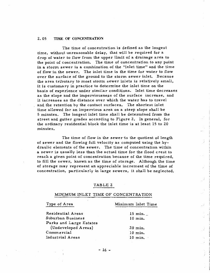
The time of concentration is defined as the longest time, without unreasonable delay, that will be required for a drop of water to flow from the upper limit of a drainage area to the point of concentration. The time of concentration to any point in a storm sewer is a combination of the "inlet time" and the time of flow in the sewer. The inlet time is the time for water to flow over the surface of the ground to the storm sewer inlet. Because the area tributary to most storm sewer inlets is relatively small, it is customary in practice to determine the inlet time on the basis of experience under similar conditions. Inlet time decreases as the slope and the imperviousne~s of the surface increase, and it increases as the distance over which the water has to travel and the retention by the contact surfaces. The shortest inlet time allowed for an impervious area on a steep slope shall be 5 minutes. The longest inlet time shall be determined from the street and gutter grades according to Figure 2. In general, for the ordinary residential block the inlet time is at least 15 to 20 minutes.
The time of flow in the sewer 'is the quotient of length of sewer and the flowing full velocity as computed using the hydraulic elements of the sewer. The time of concentration within a sewer is usually less than the actual time for the flood crest to reach a given point of concentration because of the time required, to fill the sewer, known as the time of storage. Although the time of storage may represent an appreciable increment of the time of concentration, particularly in large sewers, it shall be neglected.
TABLE 2
MINIMUM INLET TIME OF CONCENTRATION
Type of Area
Residential Areas Suburban Business Parks and Large Estates
(Undeveloped Areas) Commercial Industrial Areas
- 16 -
Minimum Inlet Time
15 min. 10 min.
20 min. 10 min. 10 min.

Table 2 gives minimum values for inlet time of concentration. All "inlet time" should be verified by direct overland flow computation.
2.06 RAINFALL INTENSITY- DURATION - FREQUENCY
a, General. It is seldom economical to design storm sewers, drains and certain types of culverts to handle the maximum runoff that may be expected to occur. Rather, storm drainage improvements are designed with the expectation that they will be overcharged once in 2, 5, 10 or 25 years on the average, an economic balance being struck between the average annual damages resulting from these occasion~l floods, on the one hand, and the cost of providing greater capacity on the other.
b. Rainfall Intensity-Duration-Frequency Relations. The relationship between rainfall intensity, storm duration and frequency vary widely from place to place, The "Rainfall lntensityDuration-Frequency" curves shown on Figure 3 have been developed by the procedures as outlined in Hydrology Handbook, A. S. C. E. , 1949, and Technical Paper No. 25, "Rainfall lntensity-DurationFrequency Curves", U. S. Department of Com_merce, Weather Bureau, December 1955.
The curves presented have been determined for durations of 5 minutes to 3-hours and return periods of 2, 5, 10, 25, 50 and 100 years.
The data analyzed for the development of these curves was abstracted from the weighing recording rain gage charts at the U. S. Weather Station at Waco, Texas. Excessive amounts of precipitation were tabulated for each period where the minimum depth of rainfall equaled or exceeded the amount considered excessive by the U. S. Weather Bureau as shown in Table 3,
The curves shown: were developed_ by the annual series method and were compared and adjusted by surrounding weather stations of longer record periods.
- 17 - f c;\

TABLE 3
EXCESSIVE PRECIPITATION
Duration in Minutes Rainfall Depth in Inches
5 0.25
10 0.30
15 0.35
20 0.40
30 0.50
45 0.65
60 o. 80
80 1. 00
100 1. 20
120 1. 40
150 1. 70
180 2.00
;:_. Design Storm Frequency. In the design of storm drainage systems, culverts, bridges, creeks, channels, etc., the relationship between the type of facility to be provided, the type of area to be drained, the time of concentration, the size of sewer and the design storm frequency, as shown in Table 4, shall govern. When any of the three conditions listed are exceeded, the design shall be based on the next more severe design frequency,
- 18 -

TABLE 4
DESIGN STORM FREQUENCY
Recom-Time of Size mendation
Description of Concen- of Design Type of Area to be tration Sewer Frequency Facility Drained (Minutes) (Inches) (Years)
Storm Residential with 30 1 84" 2 Sewers some scattered
business or commercial
Storm All areas not 30 1 84" 5 Sewers covered by 2
year frequency
Culverts, Any type of area 30' 84 11 5 Bridges, less than 100 Channels acres & Creeks
Culverts, Any type of area 45' 84" 10' Bridges, greater than: l 00 Channels acres but less than & Creeks 1, 000 acres
Culverts, Any type of area 60' 84" 25 Bridges, greater than 1, 000 Channels acres & Creeks
In connection with the design of facilities described under "Culverts, Bridges, Channels and Creeks" shown in Table 4 for areas greater than 1, 000 acres, discharges for a fifty-year frequency shall also be determined and the possible damages resulting therefrom evaluated to determine if such damages would be sufficient to warrant enlargement of the planned facilities. In any
- 19 -

area where storm runoff concentrates at low points of grade or where flow is across private property, the designer shall (1) determine discharges greater than the design discharge for all the frequencies listed in Table 4, (2) determine the depth of inundation for these discharges, and (3) evaluate the possible damages resulting therefrom, A report of these investigations shall be presented to the City Engineer for the areas in question and approval must be obtained before proceeding with design.
- 20 -

_J
I 1-w w LL
z w u z ~ en 0
3:: 0 _J LL
1000 900
BOO
700
-600
500
400
100 90
BO
70
60
50
40
30
20
0 w N ::::; w z z <1 :I: u
= c -I-z w u Li:
3: "-OW -'O "- u 0 CJ) z CJ)
= <1 w c -'z = a:: :I: I- w~ z > ::J w 00 Q a:: "-"-w 0 u
0.01
0.02(PVMT.)
0.03
0.04
0.05
w ~ _J
I-0 2: ii.
"' I
I
a z <1 _J
. a:: w
; > .o . a:: 3: Oo
v "- _J ,- _o LL
I _J
.w z z 1~
·u --' a:: "o a "- w uN - -
40 4
30 3
2.5
1-z w u II:: w a.
/ /
/ / • .--20
0;06
0.10
OJO (BARE PACKED SOIL)
0.20
0.30 (POOR GRASS)
' .Q·~ (AV. GRASS)
0.5~---
' --1.00
z
0.10 / ~ / _,..I
/ / /_,..,,.. en
l:;,o ~ ::>
1.00 z
5.0
1,0.0
20.0
::!!! ~ z 0
~ II:: I-z w u z 0 u LL 0 w ::!!!
OVERLAND FLOW GUTTER FLOW I-L' 200' L ,400' n '0.40 (AV. GRASS) n '0.02 5;: 1.0°/o 5::: l.0°/o tc' 20 MIN. le' 2.4 MIN.
TOTAL TIME OF CONCENTRATION,20.0t2.4,22.4 MIN.
NO MO GRAPH
15 1.5
10 1.0
9 0.9
8 0.8
7 0.7
6 0.6
5 0.5
4 0.4
3 0.3
FOR TIME OF CONCENTRATION
- 21 -FIGURE 2

!13d S3H:JNI NI AllSN3lNI
- 22 -
ll'i1.:INl'i1!1
FIGURE
z 0 1-<I a: => 0
...J
...J <I LL z <I a:
3
SECTION III
FLOW IN GUTTERS
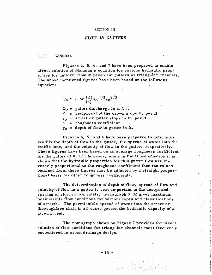
3. 01 GENERAL
Figures 4, 5, 6, and 7 have been prepared to enable direct solution of Manning's equation for various hydraulic properties for uniform flow in pavement gutters or triangular channels. The above mentioned figures have been based on the following equation:
Oo
Oo z So n
Yo
•
= = = = =
O 56 (Z) s l/2y 8/3 · (Ii)o o
gutter discharge in c. £. s. reciprocal of the crown slope ft. per £t. street or gutter slope in ft. per ft. roughness coefficient depth of flow in gutter in ft.
Figures 4, 5, and 6 have been prepared to determin" readily the depth of flow in the gutter, the spread of water into the traffic lane, and the velocity of flow in the gutter, respectively. These figures have been based on an average roughness coefficient for the gutter of O. 015; however, since in the above equation it is shown that the hydraulic properties for t;b.is gutter flow are inversely proportional to the roughness coefficient then the values obtained from these figures may be a.djusted by a straight proportional basis for other rou'ghness coefficients.
The determination of depth of flow, spread of flow and velocity of flow in a gutter is very important to the design and spacing of storm drain inlets. Paragraph 3. 02 gives maximum permissible flow conditions for various types and classifications of street's. The permissible spread of water into the street or thoroughfare shall in all cases govern the hydraulic capacity of a given street.
The nomograph shown on Figure 7 provides for direct solution of flow conditions for triangular channels most frequently encountered in urban drainage design.
- 23 -

3. 02 PERMISSIBLE SPREAD OF WATER
a, Expressways
(1) Permissible Spread of Water. The permissible spread of water in gutter of expressways shall be 8 feet measured from the outside face of curb. Gutter flow shall be based on a maximum storm duration of 15 minutes.
(2) Conditions. The maximum allowable spacing between inlets, regardless of street grade and gutter flows, shall be 500 feet. No depressed inlets shall be used unless they are clearly outside all traffic lanes.
b. Major Thoroughfares (Divided)
(1) Permissible Spread of Water. The permissible spread of water in gutters of major thoroughfares shall be limited so that one traffic lane on each side will remain clear during the design storm. Gutter flow shall be based on a maximum storm duration of 15 minutes.
(2) Conditions, Inlets shall preferably be located at street intersections or at low points of grade. Inlets shall be located, when at all possible, on off side streets or alleys when grades permit. The standard gutter depression (2-1/2 inches at inlets) shall be used so long as the depression does not fall within a traffic lane. In no case shall the gutter depression at inlets exceed 2-1/2 inches. In superelevated sections, inlets placed against the center medians shall have no gutter depression.
c. Major Thoroughfares (Not Divided)
(1) Permissible Spread of Water. The permissible spread of water in gutters of major thoroughfares (not divided) shall be limited so that two traffic lanes will remain clear during the design storm. Example: Street width 48 feet, permissible spread of water in each gutter shall be
48 1 -24 1
2 12 feet in each gutter
{assume 2 - 12' traffic lanes clear)
- 24 -

(2) Conditions. Inlets shall preferably be located at street intersections, low points of grades, or where the gutter flow exceeds the permissible spread of water criteria, Inlets shall be located, when at all possible, on the off side streets or alleys when grades permit. The standard gutter depression (2-1/2 inches) shall be used so long as the depression does not fall within a traffic lane. In no case shall the gutter depression at inlets exceed 2-1/2 inches. Depressed inlets will be permitted in a standard parking lane, Where inlets are required in traffic lanes, inlets with no depression shall be used. In superelevated sections, intercept gutter flow at P. V, C. or P. V. T. to prevent flow from crossing thoroughfare,
d. Secondary Streets.
(1) Permissible Spread of Water. The permissible spread of water in gutter of secondary streets shall be limited so that one standard lane of traffic will remain clear during the design storm. Example: Street width 36 feet, permissible spread of water in each gutter shall be:
36'-12' = 12 feet in each gutter 2
(assume l - 12 1 traffic lane clear)
(2) Conditions. Inlets shall preferably be located at street intersectionS, low points of grade or where the gutter flow exceeds the permissible spread of water criteria. Inlets shall be located, when at all possible, on off side streets or alleys when grade permits. Inlets with the standard gutter depression (2-1/2 inches) shall be used. In no case shall the gutter depression at inlets exceed 2-1/2 inches.
e. Minor Streets (Residential).
(1) Permissible Spread of Water. The permissible spread of water in gutters for minor streets shall be limited to either a 4-inch depth of flow at the face of curb or when the street is just covered. Whichever procedure produces the least depth shall be used.
- 25 -

Example: Street width 30 feet, pavement crown slope 1/4 inch per foot.
30 1
Permissible spread of water=-z- =15 feet
1 Depth of flow at curb= 15' x 4 = 3, 75"
(2) Conditions. Inlets shall be located at street intersections, low points of grade or where the gutter flow exce.eds the permissible spread of water criteria. Inlets with depressed standard gutter depression shall be used in all cases unless special grading problems are involved. In no case shall the gutter depression at inlets exceed 2-1/2 inches,
3. 03 DESIGN METHOD
In order to facilitate the computations required in determining the various hydraulic properties for gutters and roadway ditches, Computation Sheet No. 1 has been prepared and is shown in the Appendix of this manual.
The following example is given to illustrate the use of Computation Sheet No. land is shown at the end of this subparagraph.
Exarn,ple: Peak discharge for contributing drainage area 3.52 c.f.s.
q Carry-over flow from upstream inlet O. 57 c. f. s. s 0 Gutter slope O. 0050 ft. per ft. Q0 Crown slope of pavement O. 25 in. per ft. n Pavement roughness coefficient O. 015
Column 1 Inlet number or designation.
Column 2 Inlet location.
Column 3 Type of inlet.
Column 4 Contributing drainage area to inlet in acres.
- 26 -

Column 5
Column 6
Column 7
Column 8
Column 9
Column 10
Column 11
Column lZ
Column 13
Column 14
Coefficient of runoff for contributing area shown in Column 4 from Table 1.
Inlet time of concentration in minutes from Figure Z and Table z.
Intensity of rainfall in in. per hr. corresponding to the inlet time shown in Column 6 (obtained from Figure No. 3 ).
Peak runoff in c. f. s. Column 4 times Column 5 times Column 7.
Carry-over flow in c. 1. s.
Total gutter flow in c. f. s. Column 8 plus Column 9,
Gutter slope in ft. per ft,
Crown slope of pavement in ft. per ft.
Maximum depth of flow in gutter y 0 in ft.
Spread or width of gutter flow from face of curb in ft.
- 27 -

0.4
-IL
c
3: 0 0.3
IL .... Q) --:::J -
<..')
0 0,2
~ -a. Q)
0 II 0 0.1
>.
o.o 10
9
8 en u.: u c
Q) O'I .... 0 ~ (.)
5 (/)
0
.... 4 Q) --:::J
<..') 3 II
0
0 2
I
0
+
" ' '
T
..
So= Gutter Slope in Ft./Ft.
!'? "' o· o ,,.., o· 0 [()
o· o 1\1'-. o·O llJ
o· o ' o·
o<v. :!f:J
1i
I
o· o o·
Example: Oo= 4.5 C.F.S. Gutter Flow so= 0.040 Ft./Ft. Gutter Slope
0o= 1;49 or-1/4"/Ft. Crown Slope
Find: Y• = 0.195Ft,Depth of Flow in Gutter.
DEPTH DISCHARGE GUTTER FLOW
CURVES
TRAIGHT CROWN SLOPE~
n=o.015
- 28 - I FIGURE 4

24
'22
2
...: LL. c I ... CD -- 16 :J
C> c
): 14
0 LL. - 12
0
"C c CD ... Cl. en 8 II 10
ur-6 9
4 8
2 7
en 6
LL i u
5 c . CD C' .... c ..c. 0 II)
Cl
... ; CD --:J C> I II
0 0
So=~ Slope. in Ft./Ft.
o"' o· <:> cl' o·
Example : 0. • 4.5 C.F.S. Gutter Flow
o.001
•o= 0.040 Ft. Fl. Gutter Slope
9o= 1:48or114"/Ft. Crown Slope
SPREAD OF WATER DISCHARGE·
GUTTER FLOW CURVES
STRAIGHT CROWN SLOPES n=o.015
Find: Sp= 9.2 F.t. of Spread of Flow in Gutter - 2 9 - I FIGURE 5

(J)
a.: U..: c . >--u 0 Q)
> ~
Q) --::J C> II 0
>
CJ)
u..: u c ·-Q) Cl ~
c .s:::. u en . 0 ~
Q) --::J C> II
0 0
4
3
2
I
0 I
7
4
3
0
~
So= Gutter Slope m Ft./Ft.
!2 Cb co o· 0 o"> o o· o t;1-o· o
0">
o· o· o"' o·
Example: Oo = 4.5 C.F.S. Gutter Flow 1o• 0.040 Ft.IF!. Gutter Slape e.= I: 48 or 114"/Ft. Crown Slope
Find: v. = 2.55 F.P.S. Gutter Velocity
VELOCITY..-DISCHARGE
GUTTER FLOW
CURVES
I t<AJGHT CROWN SLOPES n=0.015
- 30 - I FIGURE 6

10000 9000 8000 7000 6000
5000
4000
3000
2000
----1000 900 800 700 600
500
400
300
200
100 90 BO 70 60
50
40
30
20
10
----
"' z ::; ,_ ~ ;:
EQUATION: ~;0.56(*)s}'zy!3 n IS ROUGHNESS COEFFICIENT IN MANNING FORMULA APPROPRIATE TO MATERIAL IN BOTTOM OF CHANNEL.
i! IS RECIPROCAL OF CROSS SLOPE.
REFEREJilCE H.R.B. PROCEEDINGS 1946 PAGE 150, EQUATION (14)
EXAMPLE {SEE DASHED LINES)
GIVEN: \= 0.03
i!; 241 n '" .oz l:/n : 1200
y" 0.22
100 70 ,0 30
20 FIND: Q
0-::. 2.0 C.F.S. ----To--------------------
------ z --- -- -~ -- --7
' 3 2 __
Cl' .'1 -INSTRUCTIONS
I. CONNECT i!/n RATIO WITH SLOPE (~ ANO CONNECT OISCHARGE(Ql WITi:f DEPTH{~. THESE TWO LINE~ MUST INTERSECT AT PIVOT LINE FOR
COMPLETE SOLUTION.
2. FOR SHALLOW VSHAPEO CHANNEL AS SHOWN USE HOMOGRAPH WITH
l =~
3. TO OETERMllllE
s
UJ <!> a:: <l ::c (.) Cf)
0
O!SCHARGE i<,IN ~ PORTlort OF CHANNE! 0 Y HAYING WIDTH X; ! DETERMINE DEPTH ' ,!. ~FORTOTALOIS- i.t-X l CHARGE IN ENTIRE SECTION 0. THEN USE NOMOGRAPH TO
DETERMINE Ct, JN SECTION b FOR DEPTH
(·Y~)
.5
.3
.2
.I .07 .0, .03
.02
.01
--
4. TO DETERMINE DIS- ~' CHARGE 1N COMPOSITE
SECTION: FOLLOW ! ~ I INSTRUCTION 3. • .X TO OBTAIN DISCHARGE IN ~ SECTION 0 AT ASSUMED DEPTH~ OBTAIN Q1oFOR "'~DJ)k~ SLOPE RATIO i! b ANO DEPTH y1 THEN": Qo. +-c., .
(DEVELOPED BY U.S. BUREAU OF PUBLIC ROADS.)
z
--
...J UJ z z <l ::C. (.)
LL. 0
UJ a.. 0 ...J Cf)
.10
.08
.07
.06
.05
.04
.03
.02
--
z
-----1-z
.01 0
.008
.007
.006
.005
.004
.003
.002
.DOI
a..
IC/)
UJ a.. UJ UJ 0
a:: 0
CD a:: ::> (.)
1-<l
::c la.. UJ 0
2.0
1.0
.80
.70
.60
.50
.40
.30
.20
.ID
.08
.07
.06
.05
.04
.03
.02
.01
NOMOGRAPH FOR FLOW IN TRIANGULAR GUTTERS
- 31 -FIGURE 7

BY Desi,i_ner SHEET ,......,
OF ....-._,
COMPUTATION SHEET NO. I STREET As Assiined (l7t!?st) DATE DETERMINING DEPTH AND WIDTH OF FLOW CK'D~J't£.:3r~. FOR MAJOR WATERSHED As /lssi:zped{4A)
DATE n=l7.0l5 IN GUTTERS OR ROADWAY DITCHES JOB OR FILE NO. -Is Assigned
""""' - OVER TOTAL LONGITOOINAL CROSS M.11.X. SPREAD
TYPE DRAINAGE
··-Fr~· PEAK FROM UP DEPTH OR
INLET I LOCATION I GUTTER GUTTER SLOPE OF OF WIDTH AREA STREAM OF COEFF. :r' I DISCHARGE FLOW SLOPE PVM'T. OF
NO. A INLET So eo FLOW FLOW Qo
Sp INLET ACRES C le IN./HR. Qp q FT./FT.
Yo C.F.S. FT./FT. FT. C.F.S. FT.
I I 2 3 4 5 I 6 I 7 I 8 I 9 10 II 12 13 I 14
I-C4 11?' li't Sfa. '?~()8
co-3(5') ?. .38 0.¢0 I 15' I ,g_ ?O l .3. 52 I 0. 5? 4.0~ 0.0050 //#8 0..?8 I i.s. 5
Line A#C NOTE:
fxsn>pkl Shown oj? /llustrfit-/ve .Or4'w1n9sNo.jl /No.§
REMARKS, SKETCHES AND COMPUTATIONS
I
"' N
I

SECTION IV
STORM DRAIN INLETS
4.01 GENERAL
Inlets have been classified into three major groups, namely, inlets in sumps, inlets on grade without gutter depression, and inlets on grade with gutter depression. Each of the three major classes includes many varieties. The following are presented herein and are likely to find reasonably wide use,
4.02
a. Inlets in Sumps
(1) Curb Opening (2) Grate (3) Combination (Grate and Curb Opening) (4) Drop
b. Inlets on Grade with no Gutter Depression
( 1) Grate (2) Curb Opening (3) Combination (Grate and Curb Opening)
£• Inlets on Grade with Gutter Depression
(1) Grate (2) Curb Opening (3) Combination (Grate and Curb Opening)
INLETS IN SUMPS
!: General. Inlets in sumps are inlets in low points of surface drainage to relieve ponding. The capacity of inlets in sumps must be known in order to determine the depth and width of ponding for a given discharge. Inlets on street grades less than 1 per cent shall be considered to function as inlets in sumps.
- 33 -

b. Curb Opening Inlets and Drop Inlets.
(1) General. The capacity of unclogged curb opening inlets Type CO-S and drop inlets Type D-S and Type GG-S in a sunip or low point can be considered a rectangular weir with a coefficient of discharge of 3, 0, The capacity shall be based on the following equation:
3/2 Q = 3. 0 y L
3 /2 Q/L or Q/P=3, 0 y
Q = Capacity. inc. f, s. of curb opening inlet or capacity inc. f, s. of drop inlet.
y ;= Head at the inlet in feet.
L = Length of curb opening inlet in feet.
P = Length of portion of perimeter of opening which water enters the drop inlet in feet.
The curves shown on Figures 8., 9, and 10 provide for direct solution of the above equation,
Curb opening inlets and drop inlets in sunips have a tendency to collect debris at their entrances. For this reason, the calculated inlet capacity shall be reduced by 10 per cent to allow for this clogging.
(2) Example and Explanation of Computation Sheet. In order to facilitate the computations required in determining the various hydraulic properties for curb opening inlets Type CO-S and drop inlets Type D-S and Type GG-S in sunip, Computation Sheet. No. 2 has been prepared and is shown in the Appendix of this manual.
The following example is given to illustrate the use of Computation Sheet No. 2 for both a curb opening inlet and drop inlet in a sunip and is shown at the end of this sub-paragraph.
- 34 -

Q 0 = Gutter flow= 4. 0 c. f, s.
s 0 = Gutter slope = 0, 0050 ft. per ft.
9 0 = Crown slope of pavement = 0, 25 in. per ft,
n = Pavement roughness coefficient = 0, 015
Column 1
Column 2
Column 3
Column 4
Column 5
Column 6
Column 7
Column 8
Inlet number and designation
Slope of gutter in ft, per ft.
Crown slope of pavement in ft. per ft,
Total gutter flow in c. f. s. For inlets other than the first inlet in a system, gutter flow is the sum of runoff from contributing area plus car·ry-over flow from inlet or inlets upstream.
Depth of gutter flow in feet from Figure 4 or from direct solution of Manning's equation.
3/8 3/8 3/8 Yo: 1.245 Qo n3/l6 ( l )
s tan 90 0
Depth of gutter depression in ft.
Depth of water at inlet opening in ft, Column 5 plus Column 6.
Capacity of curb opening inlet or drop inlet in c. f. s. per ft. of length of opening or perimeter around inlet from Figures 8, 9 or 10 or by direct solution.
Q or Q L p
- 35 -

Column 9
Column 10
Column 11
Column 12
Length of inlet opening or perimeter in feet.
Capacity of inlet in c. f. s. Column 8 times Column 9.
Carry-Over flow passing inlet in c. f. s. Column 4 minus Column 10.
Per cent of flow captured by inlet, Column 10 divided by Column 4 times 100,
- 36 -

~ I
to be Located a Min. of 151 from P.r.. of <!;_ of Inlet
Corner Radius ,---- --rrp 10'-o" I
l 10'-o" ' Upstream I
<:'Foce of Curb I I 'Face of Curb
" )-- - -----t
" ~
~""
~ c--- ~
0 "- ' -0 --a Slopes U . -;~ -c\, {!) SIO~ :;: ~rn/y
~ ~ ~ - -J> w I ,-Yo
--- ~????? PLAN ~ " •.. ··.r.:~. :·;: :: ///,));;~i!o ·:··:·····... ., ~ ~- ··. • • 'IJ "
·····•···.:.," .. ~ ~ o=0.20! ·.o; • .,.q: · .:i· '··. Std · .. :
SECTION A-A ···· ........ : .. ·.:~ . ::6· :: y= YrJO . ·'··.~: ::~: .... < .. ·
~ --"i3) SECTION B-B 0
' I>:. .~. : ~ .. ::::~: .. ::.:<!·. :-:: -~- ·. · .. : :~', ·_.;_;;, ~ :: '._.._ ·. ·. ,,,. ';: ;".: ·_. .~i.' :·:.l·Y.:~: ~-.:. ·1·." :.; ·,-.
I -'~~~ ·:: ·:~: :.:: ·:~.:~. ·~:> ::~ ·.:: ~- :: :. ~-:-: :~: ::·:.e.:: :: f. o.:·:. :·:.; .. t --~1.- :-. -·r,:··:~ ::-:· 4:
-J> ' .,, I
-@SECTION c-c 4.0
3.0
- -Q) 2.0 Q)
,_ I
LL. -
c 1.5
·- 11f .... I Q) I -
1.0. c - 0,9 -0.8 ~'?l'l-ll!I 0 0.7
3 0.6 -:,0 "\ 0 1-
LL. 0.5 ~o\'v .... 0 0.4_ -.c -0.3 a. Q)
CAPAC ITY FOR 0
>- 0.2 CURB OPENING 0.15 INLET IN SUMP
; TYPE co-s 0.1
0.1 0.15 0.2 0.3 0.4 05 0.6 0.7 0.8Q9 l.O 1.5 2.0
Q/L Ratio of Discharge to Curb Opening Length (C.F.S./FT)
' - 37 - FIGURE 8

li I I __ ! ______ L_
I a !
J, ' I
~ I Slope I .c I Slope
I I I I I I I I ,---- '--r-
Perimeter of Opening = 2a +2b in Feet I I
~ Mox. Water Su foe/ PLAN
'"' ''
;~ ... <::: ",:-·.·:::er::·; ... ;:·.:(!•'.•:,;;;· ,'.P .'.· -~ --,_ -' v
,~y ~N ·4:·~
" // t"'::: (.0 '--y
0 ::;.. :·.:.
·• .',q• .. .. .:-'•· :-- ".#'.
y: Ya+ o _:: ~~ ::.~ :4· .;
:~::: - :::.; w:i -Vories ~ , 18"1
SECTION A-A 4.0
3.0 - I Q) Q)
LL ' 2.0 -c ·-·-Cl 1.5 """" I. c I
·-c Q) ~j a. 0 I.~~
0.9 ~ -Q) 0.8 • -1:>\'l.--c 0.7
~9 "\ ~ -- 0.6
c
'()1~·1 -0,5 3
II 0 0.4~ - -LL . ~-
.... - -~ ~
0 0.3
.r. CAPACITY FOR -a. Q) 0.2 DROP INLETS 0
>. 0.15 IN SUMPS
I TYPE D-S 0.1
0.1 0.15 0.2 0.3 0.4 0.5 0.6 0.7 0.8 0.9 1.0 1.5 .0
Q/P Ratio of Discharge to Perimeter of Opening (C.F.S./FT.) I - 38 - FIGURE 9

.~ Slope ,, 00000000000 00000000000
Slope ~ 0 Perimeter of Opening ;;2.at2.b in Feet
Max. Water Surface PLAN
SECTION A-A
4.0
3.0
-Q) Q) 2.0
LL. c
1.5 Cl c c Q)
a. 0 0.9 - 0.8 Q)
0.7 c -0 0.5
3: 0 0.4
LL. -0.3 0
.s:::. -a. Q) 0.2
0
>- 0.15
CAPACITY FOR DROP INLET
(GRATE COVERING) IN SUMPS TYPE GG-S
0.1 .................................................. u.u. 0.1 0.15 0.2 0.3 0.4 0.5 06 0.7 0.80.9 1.0 1.5 20
Q/P Ratio of Discharge to Perimeter of Opening (C.F.S./FT).------t - 39 - FIGURE IO

BY L>~,,9ner COMPUTATION SHEET NO. 2 SHEET ,-..___
OF ~
DATE FOR DETERMINING CAPACITY OF STREET #.T .4s.r/g,..,ed
CK'D. ~'if~..{ .i; n=-- CURB OPENING INLETS AND DROP INLETS MAJOR WATERSHED As A.ss,Qned
DATE IN SUMPS OR ON GRADE {UNDEPRESSED) JOB OR FILE NO. As Assigned
DEPTH DEPTH DEPTH OF CAPACITY LENGTH CAPACITY CARRY-OVER GUTTER CROWN GUTTER OF INLET FLOW PERCENT
INLET SLOPE SLOPE FLOW OF GUTTER OF FLOW AT PER FOOT
OF INLET OF Of PVMT. FLOW DEPRESSION OPENING OPENING INLET
PASSING CAPTURED NOTES
NO. .., 0o Qo OF LENGTH
INLET Yo 0 y Q/LorP Lor P Q
BY INLET FT/FT. FT./FT. C.F.S. FT. FT. FT. C.F.S./FT. FT. C.F.S.
q
C.FS.
I 2 3 4 5 6 7 8 9 10 II 12 13
79,,,, .. co-s A:J •
./.tS/,1.fMd' 0.0050 '/-NI -<'.oo o.cs O.cl 0.¢9 /.00 4"-0,, 4.00 0.00 /00% {/.re ef!O"C0-5
79~ GG-S j/~,(/"74<1.. 1----" See Srd. .0J¥g."' I
0.0050 '/<!8 4'.00 0 . .?8 O.?I 0.4!1 1.00 7"-;,/u 7.33 o.oo 100% {/.se Tfl'l"'-GG-1
Tt,'Pe 0-5 #
See Std Dwq. o 0.0050 1/#4 400 0.?8 O.?/ 0.49 1.00 8'-0" 8.00 0.00 /00% tlse ?'-<.?' D-S
the 2 1-0'1 xC' O"_/ See Std Dwg. 111i
REMARKS, SKETCHES AND COMPUTATIONS .
I
II>-0
I

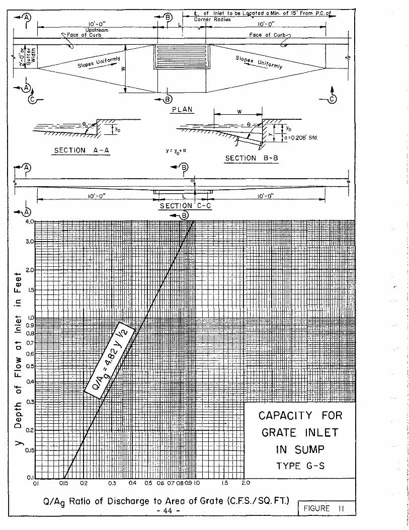
c. Grate Inlets.
( 1) General. The capacity of an unclogged grate inlet Type CG-S in a sump can be considered an orifice with a coefficient of discharge of O. 60. The capacity shall be based on the following equation:
1/2 Q : 4. 82 Ag y or
Q =Capacity in c. f, s.
Q Ag
1/2 = 4. 82 y
Ag= Area of clear opening in sq. ft.
g =Gravitational acceleration in ft. per sec. per se Co
y =Depth of flow at inlet or head at sump in feet.
The curve shown on Figure 11 provides-for dire ct solution of the above equation.
Grate inlets in sumps have a tendency to clog when flqws carry debris such as leaves and papers. For this reason, the calculated inlet capacity of a grate inlet should be reduced by 25 per cent to allow for clogging. The efficiency of grate inlets in sumps is not affected by the bar arrangement of the grating, however; gratings with bars transverse to the gutter allow for simple and economical construction.
(2) Example and Explanation of Computation Sheet. In order to facilitate the computations required in de.~ermining the various hydraulic properties for Grate Inlets Type CG-S in sumps, Computation Sheet No. 3 has been prepared and is shown in the Appendix of this manual.
The following example is given to illustrate the use.of Computation Sheet No. 3 and is shown at the end of this sub-paragraph.
- 41 -

Example:
Q 0 =Gutter flow =3. 0 c.f. s.
s 0 = Gutter slope = 0, 0050 ft. per ft,
9 0 = Crown slope of pavement = 0, 25 in. per ft.
n = Pavement roughness coefficient= O. 015,
Column 1
Column 2
Column 3
Column 4
Column 5
Column 6
Column 7
Column 8
Inlet number or designation.
Slope of gutter in ft. per ft,
Crown slope of pavement in ft, per ft.
Total gutter flow in c, f, s. For inlets other than the first inlet in a system, gutter flow is the sum of runoff from contributing area plus carry-over flow from inlet or inlets upstream.
Depth of gutter flow in feet from Figure 4, or from direct solution of Manning's equation.
3/8 Yo : 1. 245 Q 0
3/8 ( 1 )3/8 n3/16 \tan Q
0 so
Depth of gutter depression in ft,
Depth of flow at grate in ft, Column 5 plus Column 6.
Capacity of grate inlet inc. f, s. per sq. ft. of area of grate from Figure 11 or by direct solution,
Q -482 312 p;;;- . y
g
- 42 -

Column 9
Column 10
Column 11
Column 12
Area of grate in sq. ft.
Capacity of inlet in c. f, s. Column 8 times Colum:ci 9.
Carry-over flow passing inlet in c. f. s. Column 10 minus Column 4.
Per cent of flow captured by inlet. Column 10 divided by Column 4 times 100.
- 43 -
A 'r-~-----.i:'S-::":=-----;1>1--~-J,+-_• __ or-f~l-nle_t_t_o_b•_L __ a_co-te~d~o~M-in_._of_l_5'-F-ro-m-P4.C~.of Corner Radius 10'-011 10'-o" 1
Upstream .. '\:"Face of Curb
SECTION A-A
3.0
>--·-2.0 -Q) l-+-+-!-+--~4-1-++++H-l·.
Q) l--·-:j_:::j=t=1:tl=l::l::1t1:1:t1:J+1:tt11:m
- ·+-+-+++++++++++++H-i
~ l.5~f-:W:t1::ttttlttm:lttt1:Jtttlti
c 0.9 0.8
- 0.7 0
0.6 ~ 0 0.5
LL.
...... 0
0.4
~ 0.3 -0. Q)
"-..... - '"
0
~ :::lllltE:i1lmmttmllllttmR. ·-- ..
Face of Curb..., /
SECTION 8-8
I
..
CAPACITY FOR
GRATE INLET
IN SUMP TYPE G-S
t
'
'" I·
I
I I[ " 1· I I •
I 1-++-<-t-+-w+++++H+1-H++<+m++HH-HH+'4l-l-l-WI
1
~• 0.1 .............. u... ...... ...1.J..u.J..~LW.LWJ.J.WJ.L.1..J..l..l.LLW.LI.il J.JJ.lllllllL...l-l-J....l...LJ..Lll.1------------1
0.1 0.15 0.2 0.3 0.4 0.5 0.6 010.80.9 l.O 1.5 2.0
Q/Ag Ratio of Discharge to Area of Grate (C.F.S./SQ. FT.) - 44 - I FIGURE II

10'-o" 1 t.l
l,I , ~ of Inlet to Loc;QJ•d a Min. of 15' from P.C.~f Corner Radius
I 101-011
Upstream 1 1 1
1--~--t~~-~~~-ac_e_o_f_C_ur_b~~~~~ r----J--~-i\'--~~~'~,F~ac~e~o.;.;f~Cu~r~b~~~~-r---1
[ , , 0 -.-
1--.;.;~.Lg~~__.<:: s~ :;
I ..J)
PLAN
SECTION A-A Y =Yo+ a
0
(~ ; ··.'<>' :.'.·.''.>!-:.':·.'·~·~::·:.:·:~.: .::~·::·.:q:. · ....... , , I ..... . ·:_"'i·:::::.t:.: .. <·:'1: :c.~·.:::J: .. :
4.0I" -
3.0
...... 2.0 ·f- - -· Q) -··
1;:0:, -
-,_B) SECTION C--C
Slopes U .
w
' I ······· .·.·..;·· :,;::::·:~··:_:.;;::::q:·:.:~:·:·< ~-: .-_ :~::::.",4::
-~·-!·:;~·- ... A• : •...
. ·i.t
Q)
LL. 1.5 ·-
~' c
+-Q)
+- 0.8 0 0.7
3: 0.6. 0
LL. 0.5
.... 04 0
..c +- 0.3 c. Q)
0
0.2
0.15
-~
m
Ql5 0.2
'I
1.j~ :
~~~ ~ 1111
'I:>. -ol"'"' -
-
,T
-
-· -+-+-++++-H
-
- I ••. ·1-.. ---~ , H-
CAPACITY FOR
COMBINATION INLET
IN SUMP TYPE COG-S
0.3 0.4 0.5 0.6 0.7 0.8 0.9 1.0 1.5 2.0
Q/L Ratio of Discharge to Curb Opening Length (C.F.S./FT.) - 45 -
Q/Ag Ratio 'of Discharge to Area of Grate (C_F.S./SQ. FT.) FIGURE 12

BY i/2.1!'.Vf:.1"''" COMPUTATION SHEET NO. 3 SHEET ---"'-- OF ~
MTE FOR DETERMINING CAPACITY OF STREET .As AuiJ;f!L1.<"d CK'o.c~ ~r!. n=.e..e!L. MAJOR WATERSHED ,4,, As:s/9'ned
MTE GRATE INLETS IN SUMPS JOB OR FILE NO. 4;1. .!t.'5$ i;tr>...d
DEPTH DEPTH DEPTH OF CAPACITY AREA CAPACITY CARRY-OVER GUTTER CROWN GUTTER OF INLET FLO.V PERCENT
INLET SlOPE FLOW OF GUTTER OF FLOW AT PER SQ. FT
OF OF SLOPE Of PVMT. PASSING
FLOW DEPRESSION GRATE OF GRATE GRATE INLET CAPTURED NOTES NO. •• e. Oo
Aa Q INLET
Yo a y Q/AQ FT./FT. q BY INLET FT/FT. C.F.S. FT. FT. FT. C.F.S/SQ.FT SQ.FT C.F.S. C.F.S.
I 2 3 4 5 6 7 8 9 10 II 12 13
~,,, ... CG-S Att Aa111-,./ aoo4o 1/48 3.0 0.2.5 0.21 0.4~ 0.44 .J~7 /.21 /. 7P 4(}.~ /,.&,.,,,,, ... p ... ,..lh
o/ fl<>N Ft>r
i;.,.,.,,t..,.,. S/hcit!'nGff
•
REMARKS, SKETCHES AND COMPUTATIONS
I
"" a-I

Q• Combination Inlets (Type COG-S). The capacity of a combination inlet Type COG-S consisting of a grate and curb opening inlet in a sump can be considered as the sum of the capacities of an orifice and a weir and shall be determined by the two equations shown in sub-paragraphs 4. 02(,!?_.) and (,£• ). The curves shown on Figure 12 provide for direct solution of the two equations. When the capacity of the gutter is not exceeded, the grate inlet accepts the major portion of the flow. Under severe flooding conditions, however, the curb inlet will accept most of the flow since its capacity varies with y 1• 5 whereas the capacity of the grate inlet varies as yo• 5, Combination inlets in sumps have a tendency to clog and collect debris at their entrances. For this reason, the calculated inlet capacity should be reduced by 20 per cent to allow for this clogging.
4. 03 INLETS ON GRADE WITHOUT GUTTER DEPRESSION
a. Curb Opening Inlets (Undepressed) Type CO-U.
(1) General. The capacity of a curb inlet, like any weir, depends upon the head and length of overfall. In the case of an undepressed curb opening inlet (See Figure 13), the head at the upstream end of the opening is the depth of flow in the gutter. In streets where grades are greater than 1 per cent the velocities are high and the depths of flow are usually small as there is little time to develop cross flow into the curb openings; therefore, undepressed inlets are inefficient when used in streets of appreciable slope, but may be used satisfactorily where the grade is low and the crown slope high or the gutter channelized. Undepressed inlets do not interfere with traffic and usually are free from clogging with water-borne debris. Design and space inlets so that 5 to 15 per cent of gutter flow reaching each inlet will pass on to the next inlet downstream, provided the carryover is not objectionable to pedestrian or vehicular traffic.
The capacity of an undepressed curb inlet will be based on the following rectangular weir equation:
- 47 -

Q = 1. 13 5 L y 3 /2
L = Length of curb opening inlet in feet,
y = Depth of gutter flow in feet.
The curve shown on Figure 14 provides for direct solution of the above equation.
(2) Example and Explanation of Computation Sheet. In order to facilitate the computations required to determine the various hydraulic properties for Curb Opening Inlets, Type CO-U, on grade (undepres sed), Computation Sheet No. 2 has been prepared and is shown in the Appendix of this manual.
The following example is given to.illustrate the use of Computation Sheet No. 2 and is shown at .the end of this sub-paragraph.
Example:
Q 0 =Gutter flow = 2 c. f, s.
s 0 =Gutter slope = 0, 010 ft. per ft.
9 0 =Crown slope of p.;_vement = 0, 25 in. per ft.
n =Pavement roughness coefficient = 0, 015.
Column 1
Column 2
Column 3
Column 4
Inlet number or designation.
Slope of gutter in ft. per ft.
Crown slope of pavement ft. per ft.
Total gutter flow inc. f. s. For inlets other than the first inlet in a sys tern, gutter flow is the sum of runoff from contributing area plus carry-over flow from inlet or inlets upstream.
- 48 -

Column 5
Column 6
Column 7
Column 8
Column 9
Column 10
Column 11
Column 12
Depth of gutter flow in feet from Figure 4 or from direct solution of Manning's equation.
3 /8 y 0 = 1. 245 Q 0
Not required.
Column 5.
3/8 n (. l )3/8
\tan 90
Capacity of curb opening inc, f, s. per ft. of length of opening from Figure 14 or by direct solution:
3/2 Q = l. 135 y y;
Length of inlet opening in feet.
Capacity of inlet inc, f, s. Column 8 times Column 9.
Carry-over flow passing inlet inc, f, s. Column 10 minus Column 4.
Per cent of flow captured by inlet. Column 10 divided by Column 4 times 100.
The calculated capacity shall be reduced py 10 per cent to allow for clogging.
- 49 -

-r
e lJl 0
., Gi c ::u rr1
UJ
Oo,va ---
-'-Qo 1110
Yn_:,
t_ of lnle! to be Located 10' Up-grade of PC.
4> of Corner Radius
I I '-, r---,--\
-q ____,/ ~q
~ ~ PLAN
,. J. i .J. . -; ~ I I
I I r'-q
SECTION 8-8
UNDEPRESSED CURB - OPENING INLET ON GRADE TYPE CO-U
t~··.···. :·· .. , ....... ,.~ ... idf~y··r~ e~-c·~-r•·.··.
'· •,' .. ' . ' . ' ... ·"· ...... , ... '·· -: •.,
·~
: ... : ~··· .::.
SECTION A-A
-- hh ~~ )~tr0 ~77777
//));,. ~
SECTION C-C
Y =Yo

4 ' L of Inlet to be Located 10'-0° Up-grade of P.C.
of Corner Radius ,---+-4 i LI (-1
/L ____ ____ _J\
/ I -ir-' ~ Oo,vo /q
~ ~ ~~-OE'.'.19~0 PLAN
SECTION C-C Y' Yo
SECTION A:A
-~~;;===-i=I;! ~:::::-r---=~~ -.~·>. · ...... ,.· ."'~·.· .. · .· '."·.· .. ,;.· ..... .
3.0
..... Q) 2.0
~ c
-Q) -c
..... 0
3: 0
LL 0.5 -0 0.4
..c a. 0.3 Q)
Cl
>. 0.2
0.15
: ·.•a'. i : :._.: : ·: :•
'
' ·.· .. ,' ·: ..... '. :. •· .. ·::: ~· ..... : .;.• .. · ;':•·.; ..... q
CAPACITY FOR CURB OPENING
INLET ON GRADE UNDEPRESSED
TYPE CO-U 0.1 L.J...J..J-.U..U.J..U..u.J..UJ.l..W.1.1
0.1 0.15 0.2 0.3 0.4 0.5 06 0.7 OB 0.9 1.0 1.5 2.0
Q/L Ratio of Discharge to Curb Opening Length {C.F.S./FT.) -·------i - 51 - FIGURE 14

BY Oe:n2n~.r COMPUTATION SHEET NO. 2 SHEET ,..,___
OF ~
DATE FOR DETERMINING CAPACITY OF STREET ,4.s -4.rs/'il.nea' • c,~.En,,.r'.:>. n= MAJOR WATERSHED As 4s.s/2ned CK D. e ,1;,:; -- CURB OPENING INLETS AND DROP INLETS
DATE IN SUMPS OR ON GRADE (UNDEPRESSED) JOB OR FILE NO. As 4.>S/gn«:d
DEPTH DEPTH DEPTH OF CAPACITY LENGTH CAPACITY CARRY-OVER GUTTER CROWN GUTTER OF ll'LET FLOW PERCENT
INLET SLOPE SLOPE FLOW OF GUTTER OF FLOW AT
PER FOOT OF INLET OF
OF PVMT. PASSING FLOW DEPRESSION OPENING OF LENGTH . OPENING INLET CAPTUREO NOTES
NO. "o 00 Oo INLET Yo a y Q/LorP Lor P Q
BY INLET FT/FT. FT/FT. C.F.S. FT. FT. FT. C.F.S./FT. FT. C.F.S.
q
C.FS.
I 2 3 4 5 6 7 8 9 10 II 12 13 ,,,., /lss1gnea' cJ.010 '/4d c..o o.1g r'-- 0. /9 0. 0.98 10:-0" O.:J8 /.O? -If.(;. 5 '% Use 10 '-cJ• "?""'-
4SSG -n~a' L •ngl-h _/
or £'~V/V.g/enl mg
REMARKS, SKETCHES AND COMPUTATIONS
I
U1 N
I

b, Grate Inlet on Grade (Undepressed} Type CG-U
(1) General. Undepressed grate inlets (See Figure 15) on grade basically have a greater hydraulic capacity than curb inlets of the same length so long as they remain unclogged. Grate inlets on grades of one per cent and less shall be considered as inlets in sumps and shall be determined by the procedure for 'inlets in Sumps"; however, grate inlets on grades steeper than one per cent propose a more complex problem. Generally speaking, undepressed grate inlets on grade are inefficient in comparison to other types of inlets; however, they do not interfere with traffic. Grate inlets should be so designed and spaced so that 5 to 15 per cent of the gutter flow reaching each inlet will pass on to the next downstream inlet, provided the carry-over is not objectionable to pedestrian or vehicular traffic.
Grates with bars parallel to the curb should always be used for the above described installations because transverse framing bars create splash which causes the water to jump or ride over the grate. For flows on streets with grades less than one per cent, little or no splashing occurs regardless of the direction of bars.
The calculated capacity for a grate inlet shall be reduced by 25 per cent to allow for clogging.
(2) Example and Explanation of Computation Sheet. In order to facilitate the computations required to determine the various hydraulic properties for Grate Inlets, Type CG-U, on grade (undepressed}, Computation Sheet No. 4 has been prepared and is shown in the Appendix of this manual.
The following example is given to illustrate the use of Computation Sheet No. 4 and is shown at the end of this sub-paragraph.
- 53 -

Example:
Q 0 = Gutter flow= 2. 0 c. f. s.
s 0 =:Gutter slope= O. 010 ft. per ft.
9 0 =Crown slope of pavement = O. 25 in. per ft.
n =Pavement roughness coefficient = O. 015.
Column 1
Column 2
Column 3
Column 4
Column 5
Column 6
Column 7
Column 8
Inlet number or designation,
Slope of gutter in ft. per ft.
Crown slope of pavement in ft. per ft,
Total gutter flow inc. f. s. For inlets other than the first inlet in the system, gutter flow is the s urn of runoff fr om contributing area plus the carry-over flow from the inlet or inlets upstream.
Depth of gutter flow in feet from Figure 4 or from direct solution of Manning's Equation.
3/8 y
0: 1.245 Q 0
n3 /8
3f16 So
( 1 )318
tan 90
Gutter velocity in feet per second from Figure 5 or from direct solution of continuity equation v 0 = Qof A where A is the cross-sectional area of flow in gutter or by Manning's Equation.
1/4 1/4
Length of grate in feet.
Column 5 divided by (g) and the quotient raised to the 1 /2 power.
- 54 -

Column 9
Column 10
Column 11
Column 12
Column 13
Column 14
Column 15
Length of grate required to capture 100 per cent of all flow over grate in ft.
or
L 0 = M times Column 6 times Column 8
M = Grate coefficient where: M • 4. 0 for grate inlets if no large transverse bars are flush with the grate surface; and M = 8, 0 for grate inlets if flush transverse bars are us ed.
Width of grate in feet. Distance from face of curb to outside openings in grate.
Tangent of crown slope.
Column 10 divided by Column 11.
Column 5 minus Column 12.
Column 13 divided by (g) and the quotient raised to the 1/2 power.
Length of grate required to capture the outer portion of gutter flow in feet.
- 55 -

Column 16
Column 17
Column 18
Column 19
Column 20
Column 21
w 1/2
L 1 = 1, 2 -~o) or
L' = 1, 2 times Column 6 times Column 11 times Column 14.
Column 15 minus Column 7.
Column 13 raised to the 3 /2 power.
Carry-over flow in c. f. s, outside of the grate.
q 2 :1,42(L1-L) (y W ) 3 / 2 0 - tan G
0
or
q2 = 1, 42 times Column 16 times Column 17,
Column 7 divided by Column 9 raised to the 2 power. Computation not required for combination inlets.
Carry-over flow inc. f, s. between the curb and grate. Computation not required for combination inlets.
or
q3 : Column 4 times (1 minus Column 19) raised to the 2 power.
Total carry-over flow inc. f. s. passing grate. Same as Column 18 for combination inlets. q2 + q 3 : Column 18 plus Column 20.
- 56 -

Column 22
Column 23
Capacity of inlet in c. f. s. Column4 minus Column 21.
Per cent of flow captured by inlet. Column 22 divided by Column 4 times 100,
- 57 -

~ I
-r t. of Inlet to be Located 10' Up-grade of
P.C. of Corner Radius-.
L
! I 0- .. I I · Q3 -er- '-../' I ' ·:·•:::. :~":.:e:: :-.~.:~:.·.:~11: .. y
I I ... QO,'IJO '7 ' ;;: -~.
I I I ------- ..
' "' , .•
·.· -.
~ ~ SECTION A-A
ct- PLAN ~ I
lJ' 6SJJJJJ 00
I } -,, ,, ,, ; ;; ; , : ,, n
' c Yo Oa,vo
/,
• ' , ~q SECTION C-C
SECTION 8-8
FYo
,__ UN DEPRESSED Tl Gl c GATE INLET ::u ON GRADE TYPE CG-U [Tl
(}1

BY Oes1£ner COMPUTATION SHEET NO. 4 SHEET ~ OF ~
DATE STREET As 4ss1gne:d
CK'o. c1J.,..fs"c''}n:t:l.015 FOR DETERMINING CAPACITY OF GRATE OR MAJOR WATERSHED As Assi9n,..c1
DATE COMBINATION INLET ON GRADE (UNDEPRESSED) JOB OR FILE NO. As Ass1~nea'
GUTTER CROWN GUTTER DEPTH GUTTER LENGTH WIDTH
INLET SLDPE DF GUTTER OF GRATE Yo r Lo= DF y,
SLDPE FLOW VELOCITY •• DF PVr.IT (~t· w w w FLDW DR CURB (-g GRATE TAN 0 TANB0
Yo-TANBo 'Yo-TANB0)
ND. •o Bo Co •o DPENING M •o g 0
Yo w FT/FT. C.F.S. F.P.S.
L FT/FT. FT. FT. SEC. FT. ;If FT. FT. FT. \ s:c.
I 2 3 4 5 6 7 B 9 10 11 12 13 14
0.010 1/48 .?. 0 0.19 2.00 4 1-0'' 0.0?7 o. ?7 1..J.J 48 0.0?7? 0.10 0.07/
I.! = q. = q = 3
ND TES Q: * When
1.2 •Col.6 t-L (Col.13)~ l42 • Col.16 (~)· ~ I!)' g (IDD) L < L
0 or L1 Compute q3 q.+q, co-q.+q, •Col.llaCol.14 • Cot.17 Lo c,, I- 7T L > L
0or L1 q,=O LO 0
FT. FT. (FT.)~ C.F.S. • CF.S. lf C.F.S. C.F.S . % q3 Not Required For Combination Inlet
15 16 17 18 19 20 21 22 23 24
10.? G. ?' 0.0G4 0.56 '""'-' ~ 0.56 1.44 ??% Use I, Tqpe CG-U', Spaee Further
ApBrt f'or Greafer Ef'f'1ciencJ1.
- I
- "' "' -·'

c. Combination Inlet on Grade Undepressed (Type COG-U.
( 1) General. Undepres sed combination (curb opening and grate) inlets on grade have greater hydraulic capacity than curb inlets or grate inlets of the same length (See Figure 16). Generally speaking, combination inlets are the most efficient of the three types of undepressed inlets presented in this manual. Grates with bars parallel to the curb should always be used. The basic difference between a combination inl_et and a grate inlet is that the curb opening receives the carry•over flow that falls between the curb and the first grate opening. The calculated capacity of a combination inlet should be reduced by ZO per cent to allow for clogging.
(Z) Example and Explanation of Computation Sheet (Combination Inlet) (Type COG-U). The example of calculating the capacity of an undepressed combination inlet is essentially the case of the undepressed grate inlet and is also shown on Computation Sheet No. 4 in the Appendix of this manual. However, the coefficient "M" used to determine L 0 is different for the combination inlet and are as follows:
M = 3. 3 for inlets if no large transverse bars are flush with the grate surface.
M = 6. 6 for inlets if flush transverse bars are used.
- 60 -

t. of Inlet to be Located 10' Up~grade of P.C. of
~ Corner Radius "
-J I L I I I
'
Oo,vo L _______ ~
~ ~ ~ PLAN
~ f ca • «d l.c - 1 i ' j 0 1vo ' y --'I I:;'.
!--,, G) c :u fTl
(J)
0 ·«.1
:~::
SECTION
I·'' ~·.: '::~
8-8
'( q
UNDEPRESSED
COMBINATION INLET
ON GRADE TYPE COG-U
::..':: .. '';.":;·~'.: ~·: ~-.:,;,1 \
~: .;·~:
,:·':' 4,.:
90~ ~.;;:
\ f.: :.~ <i/1 it;. ·'
SECTION A-A
- ; / ; ; -; ;---;-;--- !\~-.Yo ~7777/
/ ; ? ; ·___t_:_: , /
SECTION C-C
Y =Yo
y

4,04 INLETS ON GRADE WITH GUTTER DEPRESSION
.!!:.• Curb Opening Inlets on Grade (Depressed) Type co-D.
(1) General. The depression of the gutter at a curb opening inlet (See Figure 17) below the normal level of the gutter increases the cross-flo:w towards the opening, thereby increasing the inlet capacity. Also, the downstream transition out of the depression causes backwater which further increases the amount of water captured. Depressed inlets should be used on continuous grades that exceed one per cent although the use in traffic lanes should be avoided whenever possible.
The depression depth, width, length and shape all have significant effects on the capacity of an inlet; therefore, to simplify the design of all new depressed inlets, the following standard depression shall be used:
a = 0, 208 1 or 2-1/2 11 =Standard depression below standard gutter grade,
w0 =4 1.-0 11 : Standard width of depression, measured from face of curb.
L 1 =10 1-0 11 : Standard upstream curb and gutter transition.
L 2 = 5 1-0 11 = Standard downstream curb and gutter transition.
The capacity of a depressed curb inlet . will be based on the following equation:
3 /2 Q = (C+O, 2) 5. 68 L y
Q =Capacity of inlet inc. f, s,
C =Constant
L = Length of curb opening in ft.
y = Depth of flow at inlet in ft.
- 62 -

(2) Example and Explanation of Computation Sheet for Curb Opening Inlet (Depressed), In order to facilitate the computations required in determining the various hydraulic properties for Curb Opening Inlets Type CO-Don grade (Depressed), Computation Sheet No. 5 has been prepared and is shown in the Appendix of this manual.
The following example is given to illustrate the use of Computation Sheet No. 5 and is shown at the end of this sub-paragraph.
Example:
Oo =
Bo =
llo = n =
Column 1
Column 2
Column 3
Column 4
Column 5
Gutter flow : 4, 0 c, f, s,
Gutter slope = o. 020 ft. per ft,
Crown slope of pavement = 0, 25 in. per ft,
Pavement roughness coefficient • o. 015.
Inlet number or designation.
Slope of gutter in ft, per ft.
Crown slo.pe of pavement in ft. per ft.
Gutter flow in c, f, s. For inlets other than the first inlet in the system, gutter flow is the sum of the runoff from contributing area plus carry-over flow from the inlet or inlets upstream.
Depth of gutter flow at upstream end of gutter transition in feet from Figure 4 or from direct solution of Manning's Equation:
- 63 -
n3/8 ( 1 )3/8 s 3716 tan 90 0 .

Column 6
Column 7
Gutter velocity inf, P• s. from Figure 'i: or direct solution of continuity <;'quation v 0 : Q 0 I A where A is the cross-sectional area of flow in gutter at the upstream end of gutter transition or by Manning 1s Equation.
1/4 v
0 = 1.288 Q 0
3/8 1/4
:~ /4 (ta; e0 )
Gutter velocity head in ft. from Table 30.
Column 8 'Cross slope of gutter depression in ft. per ft.
Column 9
Column 10
Column 11
Column 12
Column 13
Column 14
Column 15
Column 16
Depth of depression at face of curb in feet.
Width of depression in feet measured from face of curb out.
Total specific energy of flow in ft. measured at the upstream end of gutter transition,
2 , VO
E:y +-+a 0 2g
Depth of flow at curb opening in feet. (See Figure 49 to 53)
Length of inlet opening in feet.
Length of upstream gutter transition in feet.
Length of downstream gutter transition in feet.
Tangent of depression cross slope.
- 64 -

Column 17
Column 18
Column 19
Column 20
Column 21
Column 22
Column .23
2(E - l) = 2 (Col. 11 - l) = F Y Col. 12
Column l3 divided by the product of Column 9 and Column 16.
Column 17 times Column 18: Coefficient M
0.45 : c (l.l2 ) Col. 19
5, 68 times Column 12 raised to the 3 /2 power
(O. 20+C) = O. 20 + Column 20,
Capacity of inlet inc. f, s. per ft, of length of curb opening.
~: (0.20+C) 5. 68 y3 /
2
or
Q = Column 22 times Column 21. L
Column 24 Capacity of inlet inc. f. s. Column 23 times Colmnn 13,
Column 25 Carry-over flow in c. f, s. passing inlet. Column 4 minus Colmnn 24.
Column 26 Percentage of flow captured by inlet. Column 25 divided by Colmnn 4 times 100.
The calculated capacity shall be reduced by 10 per cent to allow for clogging.
- 65 -

L of Inlet to be Located 10' Up-grade of P.C.
~ of Corner Radius
-rp ,, I· : · \~·.;- : _ I I '----- ~ , • ==-::.}- I
I I I I l So -
L
~
~ Jr--
0
0 '"'
::' {)
v gt"' ·u; " ~ ~ ~
c. 0
~~
~ -J PLAN
~ t_ ~ -=- !t J. Ii-===·~ • I I y a : \ q
" Gl c ;o fTI
--J
SECTION 8-8
DEPRESSED CURB - OPENING INLET ON GRADE TYPE CO-D
v 2 E=~+=+a a 2g
'&
'•.-v:• .. ,\,.I_. P';-C." - ~.d·~::• ;··~~·:·.:· ~::.:~. . , ,y I
.. 'G··. ~??· 1··· ·!I. ... :.-~!'".:.·.·~:;;-.... a:.:.
----·'. ·~~.~ -~
SECTION A-A
IL :: ·~1
~:
·•.
a ~---~- Yo
:e/7777 -=;-.,l)/J;;;;; ~
SECTION C-C
Sid. Depression
Lt = 10'-o" L2 = s'-o" L = Varies W= 4
1-0
11
a ' a = 0.208 9 = Varies 9
0= Vories

BY Des/!l.ner COMPUTATION SHEET NO. 5 SHEET ,...__.
OF ,...._,
DATE FOR DETERMINING CAPACITY OF STREET 4.r 4.rs/<;:.ne d I C/i £,.,.r•.n: a 0/:5 MAJOR WATERSHED ,b ,b-.S/izned CK D. P e,;;;c;.
DATE CURB OPENING INLET ON GRADE (DEPRESSED) JOB OR FILE NO. 4,- .4.rs,g/7eal
GUTTER CROWN GUTTER DEPTH GUTTER GUTTER DEPRESSION DEPTH WIDTH SPECIFIC DEPTH LENGTH LENGTH LENGTH
INLET SLOPE $LOP6 FLOW OF GUTTER VELOCITY VELOCITY
CROSS OF. OF ENERGY OF FLOW OF INLET OF UP-ST. OF DN.-ST
OF PVMT FLOW HEAD ~PRES SI ON DEPRESSIO~ OF FL9W AT OPENING OPENING l"RANSITION rRANSITION NO. .... e., Qo Vo ~ SLOPE
Yo 0 ~ E=~+~ y L L1 L, 2g 9
FT/FT. FT/FT. C.F.S. FT. F.PS. FT. FT/FT. FT. FT. FT. FT FT. FT. FT.
I 2 3 4 5 6 7 8 9 10 II 12 13 14 15
0.0/?0 1/48 4.oo 0.21 ;?. ?o 0.11 0..Y.8 0.ZI ?'-0"" 0.:53 0.40 4 1-0"' /O~O" 6'-0''
As .4.s.5<- '??"'d :fl
.
CAPACITY CMRY-OVEF
' ~= OF FLOW PERCENT
F= M= c= TAN 9
L 5.68Y "2 (0.20+Cl Col.21 l Col 22 INLET PASSING CAPTURED NOTES z (f-1) a TAN9 -'=.L 0.45
1.12" INLET
a TAN9 Q 9Y INLET C.F.S.
q
C.F.5./FT. C.F.S. Q/Oo
16 17 18 19 20 21 22 23 24 25 26 27 \ 13. a 0.,;;; GO /. 81!! 0.9/ 0. 41 /. 44 O.~I 0.88 8.5.!!" 0.4-8 88.0% (/.re 4 '-o" lnler T§tpe Ct::?-o
See S~d. Dwg. No. I
-, ,_a-_, ,_.

b. Grate Inlets on Grade (Depressed) Type CG-D.
(1) General. The depression of the gutter at a grate inlet decreases the flow past the outside of a grate. The effect is the same as that when a curb inlet is depressed, namely the cross slope of the street directs the outer portion of flow towards the grate (See Figure 18),
The bar arrangements for depressed grate inlets on streets with grades greater than one per cent greatly affect the efficiency of the inlet. Grates with longitudinal bars eliminate splash which causes the water to jump and ride over the cross bar grates, and it is recommended that grates have a minim= of transverse or cross-bars for strength only.
For low flows or for streets with grades less than one per cent, little or no splashing occurs regardless of the direction of bars. However, if the flow or street grade increases, the grate with longitudinal bars becomes progressively more superior to the cross bar grate. A few small rounded cross-bars, installed at the bottom of the longitudinal bars as stiffeners or a safety stop for bicycle wheels, do not materially affect the hydraulic capacity of longitudinal bar grates.
Grate inlets in depressions have a tendency to clog when gutter flows carry debris such as leaves and papers. For this reason the calculated inlet capacity of a grate inlet shall be reduced by ZS per cent to allow for clogging.
The depression depth, width, length and shape all have significant effect on the capacity of any inlet; therefore, to simplify the design of all new depressed grate inlets, the standard depression shown in paragraph 4, 04 shall be used.
(Z) Example and Explanation of Computation Sheet for Grate Inlet on Grade (Depressed) (Type CG-D). In order to facilitate the computation required in determining the various hydraulic properties for grate inlet on grade, Type CG-D (Depressed), Computation Sheet No. 6 has been prepared and is shown in the Appendix of this manual.
- 68 -

The following example is given to illustrate the use of Computation Sheet No. 6 and is shown at the end of this sub-paragraph.
Example:
Q 0 =Gutter flow = 4. 0 c. £. s,
s 0 =Gutter slope = O. 020 ft, per ft.
90 =Crown slope of pavement = O. 25 in. per ft.
n =Pavement roughness coefficient ::; O. 015.
Column l
Column 2
Column 3
Column. 4
Column 5
Column 6
Inlet number or designation.
Slope of gutter in ft, per ft.
Crown slope of pavement in ft. per ft.
Total gutter flow in c. f, s. For inlets other than the first in system, gutter flow is the sum of runoff from the contributing area plus the carry-over flow from the inlet or inlets upstream.
Depth of gutter flow in feet from Figure 4 or from direct solution of Manning's Equation.
3/8 ~ l )3/8 Yo= l.245 Qo R~3/Y6\tan 90
So
Gutter velocity in feet per second from Figure 5 or from direct solution of continuity equation v 0 : Q 0 /A, where A is the cross-sectional area of flow in the gutter or by Manning's Equation.
1/4
- 69 -
s 3 /8 0
n3/4

Coltunn 7
Coltunn 8
Column 9
Column ,10
Coltunn 11
Coltunn 12
Coltunn l3
Coltunn 14
Coltunn 15
Coltunn 16
Coltunn 17
Depth of depression at face of curb in feet.
Width of depression measured from face of curb.
Cross. slope of gutter depression in ft. per ft.
Length of grate in feet.
Width of grate in feet.
R = ratio of total width of clear openings to the width of grate, usually about 0, 50 to 0, 60 for cast iron or steel grates.
Total specific energy of flow in feet measured at the upstream end of gutter transition.
v 2 0
E =Yo+ - +a 2g
Depth of flow at upstream edge of grate in feet (See Figure 49 to 53),
Gros a-sectional areas of gutter flow at grate in sq. ft. (See Figure 48).
Mean velocity of flow at upstream edge of grate inf. p. s. Column 4 divided by Column 16.
(Column 14 divided by 32, 2) all raised to the 1/2 power.
- 70 -

Column 18
Column 19
Column 20
Column 21
Column 22
Column 23
Column 24
Length of grate required to capture 100 per cent of all flow over grate in ft.
L 0 = M times Column 6 times Column 8.
M : Grate coefficient where: M = 4. 0 for grate inlets if no large transverse bars are flush with the grate surface; and M = 8. 0 for grate inlets if flush transverse bars are used.
Tangent of depression cross slope.
Column 11 divided by Column 19.
Column 14 minus Column 20.
Column 21 divided by 32, 2 all raised to the l/2 power.
Length of grate required to capture the outer pcrtion of gutter flow in feet.
w ~1/2 Yo - taiitl
L' : l, 2 Vo tan eo( g 0
or
L' = 1. 2 times Column 16 times Column 19 times Column 22,
Column 23 minus Column 10,
- 71 -

Column 25
Column 26
Column 27
Column 28
Column 29
Column 21 raised to the 3 /2 power.
Carry-over flow inc. f, s. outside of the grate.
or
w 3/2 : 1,42 (L'-L) (y0 -t Q ) an 0
q2
: 1, 42 times Column 23 times Column 25.
Column 10 divided by Column 18 raised to the 2 power. Computation not required for combination inlets.
Carry-over flow inc. f, s. between the curb and grate. Computation not required for combination inlets.
or
q3 : Column 4 times (l minus Column 2 7) raised to the 2 power,
Total carry-over flow in c. f. s. passing grate. Same as Column 2 6 for combination inlets.
q 2 + q3 = Column 26 plus Column 28.
- 72 -

Column 30 5, 68 times Column 10 divided by Column 29.
Column 31 Column 30 raised to the 2 /5 power.
Column 32 Column 7 minus L2 times Column 2 L2 = Length of downstream gutter transition.
Column 33 Value for abscissa on Figure 54. Column 31 times Column 32,
Column 34 Tan 9 divided tan 90
used to interpolate from Figure 54,
Column 35 Value for ordinate from Figure 54.
Column 36
Column 37
Column 38
Interpolate for R (Column 12) and tan 9 divided by tan 9 0 (Column 34)
q divided by sum of q 2 and q3
Carry-over flow inc. f. s. passing the inlet. Column 29 times Column 35,
Capacity of inlet inc. f. s, Column 4 minus Column 36.
Percentage of flow captured by inlet. Column 37 divided by Column 4 times 100,
The calculated capacity should be reduced by 20 per cent to allow for clogging.
- 73 -

-rr ~ L L2 L,
q
Qo,vo
~
~ PLAN ~
f ----..) If I . ' - "• "• '" ··_1 ''-y
"TJ G> c ::a ITl
00
SECTION B-B
DEPRESSED GRATE INLET
ON GRADE TYPE CG-0
v 2 E=yo + 2~ +a
,z~·~·:··:· ~ ·::.=:~~;:~:;;~: ··~; .. """"' . '"'13:···
;o·~,
1.' .:
Wo
w
" y 1·.;.
fl.., I t·9:
,. ·.~·
SECTION A-A
'.,,,,"'
y a
w/7 ~~~ : SECTION C-C
Std. Depression
L = 10'-o" I Lz = 51-0" L = Varies W= 41 -0
11
0 ' a= 0.208 9 = Varies 9
0= Varies

BY .Oe$'2.her COMPUTATION SHEET NO. 6 SHEET ~
OF ....___...
~~:E ~~,!:;r'fi=_ FOR DETERMINING CAPACITY OF GRATE OR STREET A:s ,l/5s;9ned
MAJOR WATERSHED .45 ,1J5s1£ned
DATE COMBINATION INLET ON GRADE ( DEPRESSED} JOB OR FILE NO. .4s .4ss1jnec/
GUTTER CROWN GUTTER DEPTH GUTTER DEPTH WIDTH DEPRESSION LENGTH WIDTH R=RATIO OF SPECIFIC DEPTH
SLOPE OF GUTTER OF OF CROSS OF GRATE OF CLEAR ENERGY OF FLOW INLET SLOPE OF PVMT FLOW VELOCITY OR CURB OPENING
FLOW DEPRESSION DEPRESSION SLOPE OPENING GRATE WIDTH OF FLOW AT GRATE NO. •o a., Qo
Yo Yo
0 Yob e L w TO WIDTH E=y0+f/-+a y
FT/FT FT./FT . C.F.S. FT. F.P.S. FT. FT. FT/FT. FT. FT. OF GRATE FT. FT
I 2 3 4 5 6 7 8 9 10 II 12 13 14
o. o.?o '/48 4.00 0. i?I ?. 70 0.i?I 4 1-0N I/ 1.3..!J t/ 1-0 JI 1.3.3 CJ.GO 0.53 0.4tJ
CROSS SECTIONAL VELOCITY w ~ AREA OF OF FLOW (+lr. t,,= t-~ANB) L1=1.2xCol.16x r. 'l21.42xCol.24
( _!,_ )'
q,= w w
(Y- TA~B) L' 2 FLOW AT INLET
Mv(f)~ TAN 9
TANB y - 'i'liN9 Col.19xCol. 22 t!-L xCol. 25 aa(1- ;:zl y La A 0
<FT1 F.P.S. SEC. FT FT. SEC. FT. FT. {FT.j/2 • FT. Ii C.F.S. C.F.S.il
15 16 17 18 19 20 21 22 23 24 25 26 27 28
1.35 i?.9G 0. llJ /. ,?,? 13. 8 0.09G 0..30 O.O!Tt;i44 4. 7?' 0. 7.?' 0. IG4.J' 0.17 ,...., ~
NOTES
{g)~B Ii WMn
L<L0orl1 Compute q 3
{Col 30~~ TAN B _q_ Q= Q qlq. q,+q,
(a - '!}-,l Col.31 xCol32 TANB0 q,+q,
q Qo-q Qo
L >L0or L1 q
3 =O
q3Not Required For Combination Inlet
C.F.S. {FT.)~' (FT.f"' FT. Ii CF.S. C.F.S. · ~:Upstream Gutter Transition.
1 -"' Do.nstream Gutter Transition.
29 30 31 32 33 34 35 36 37 38 39
0.17 4Gc 1170 0.1/ I. ,? .:J 0.?9 0. .?5 0.04 3 . .:JG .99 04' Use 4'-0" Tf!pe CG-D
- ' See Std Dwg. No.? ...,
-"' '

c. Combination Inlet on Grade (Depressed) Type COG-D.
(1) General. Depressed combination inlets (curb opening plus grate) have greater hydraulic capacity than curb opening inlets or grate inlets of the same length. Generally speaking, combination inlets (See Figure 19) are the most efficient of the three types of depressed inlets presented in this manual. Grate with bars parallel to the curb should always be used for maximum efficiency. The basic difference between a combination inlet and a grate inlet is that the curb opening receives the carry-over flow that passes between the curb and the grating. The calculated capacity of a combination inlet should be reduced by 20 per cent to allow for clogging.
The depression depth, width, length and shape all ha;ve significant effect on the capacity of any inlet; therefore, to simplify the design of all new depressed combination inlets, the standard depression shown in Paragraph 4. 04 shall be used.
(2) Example and Explanation of Computation Sheet for Combination Inlet on Grade (Depressed) (Type COG-D). The example of calculating the capacity of a depressed combination inlet is essentially the case of the depressed grate inlet and is also shown on Computation Sheet No. 6 in the Appendix. However, the coefficient "M" used to determine L
0 are different for combina
tion inlets and are as follows:
M = 3. 3 for inlets if no large transverse bars are flush with the grate surface,
M = 6. 6 for inlets if flush transverse bars are used.
- 76 -

-r L,
4) ~
G. of Inlet to be 10' Up-grade of P.C. of .----,-------"\a .. Corner Radius
L2
1--+---------__J, r----;----1 1-, -----1-----1
Oo,vo
--J> J;=
....,
....,
" G)
c ;:o fTI
(.0
• )
'-y 0
PLAN
I :;..:::> I
-y 'o 1
SECTION 8-8
DEPRESSED COMBINATION INLET
ON GRADE TYPE COG-D
Q ~
~
i~ •
2 :!2: +a E =y + 2g
Wo I
w I r.:~~~·:.·, a.·:;'
f->:·.-:.:~4.·W~:l ty ···~,·· ~·· a :.~ ··: _· ... '·.:c:, .,_ ... :, - .•.
SECTION A-A
eg1;777 - /))/~;~)) 1::0 SECTION C-C
Std. Depression
L - 10-0" L~: 5'-0" L = Varies Wr;= 4'-011
a = 0.208' 9 = Varies 9 = Varies
0

- 78 -

5. 01 GENERAL
SECTION V
FLOW JN STORM DRAINS AND THEIR APPURTENANCES
Since a general description of storm drainage systems and the quantities of storm runoff has been discussed in Section II of this manual, it is the purpose of this section of the manual to consider the significance of the hydraulic elements of storm drains and their appurtenances to storm drainage system.
Hydraulically, storm drainage systems are conduits (open or closed) in which unsteady and non-uniform free flow exists. Storm drains accordingly are designed for open-channel flow to satisfy as well as possible the requirements for unsteady and nonuniform flow. In many instances steady flow conditions may be either uniform o·r non-uniform.
5.02 VELOCITIES AND GRADES
a. Minimum Grades. Storm drains should operate with velocities of flow sufficient to prevent excessive deposits of solid materials; otherwise objectionable clogging may result. The controlling velocity is near the bottom of the conduit and considerably less than the mean velocity of the sewer. Storm drains shall be designed to have a minimum mean velocity flowing full of 2. 5 f. p. s. Table 5 indicates, the minimum grades for both concrete pipe (n = O. 013) and for corrugated metal pipe (n = O. 024), flowing at2.Sf.p.s.
b. Maximum Velocities. Maximum velocities in sewers are important mainly because of the possibilities of excessive erosion on the storm drain inverts. Table 6 shows the limiting conditions of maximum velocity for most storm drainage design •.
- 79 -

TABLE 5
MINIMUM GRADES FOR STORM DRAINS
Pipe Size Concrete Pipe Corrugated Metal Pipe (Inches) Slope Ft, /Ft. Slope Ft. /Ft,
I5 0.0023 0.0076
18 o. 0018 0.0060
21 0.0015 0.0049
24 o. 0013 0.0041
27 o. 001-l 0.0035·
30 0.0009 0.0031
33 0.0008 0.0027
36 o. 0007. o. 0024·
39 0.0006 0.0022
42 0.0006 0.0020 45 0.0005 0.0018 48 o. 0005 o. 0016 54 0.0004 0,0014
60 0.0004 0.0012 66 0.0004 o. 0011 72 0.0003 0.0010 78 0.0003 0.0009 84 0.0003 0.0008 96 0.0002 0,0007
TABLE 6
MAXIMUM VELOCITY IN STORM DRAINS
Description
Culverts (all types) Storm Drains (inlet laterals) Storm Drains (Collectors) Storm Drains (Mains)
Maximum Permissible Velocity
15£.p.s. No Limit 15 £. p, S.'
12 £. p. s.
- 80 -

5. 03 MATERIALS
In selecting roughness coefficient for concrete pipe, between O. 013 and O. 015, consideration will be given to the average conditions at the site during the useful life of the structure. The "n" value of O. 017 for concrete pipe shall be used primarily in analyzing old sewers where alignment is poor and joints have become rough. If, for example, concrete pipe is being designed at a location where it is considered suitable, and there is reason to believe that the roughness would increase through erosion or corrosion of the interior surface, slight displacement of joints, or entrance of foreign materials, a roughness coefficient will be selected which, in the judgment of the designer, will represent the average condition. Any selection of "n" values below the minimum or above the maximum, either for monolithic concrete structures, concrete pipe or corrugated metal pipe, will have to have the written approval of the City Engineer.
The following recommended coefficients of roughness are listed in Table 7 and are for use in the nomographs contained herein, or by ·direct solution of Manning's Equation.
TABLE 7
ROUGHNESS COEFFICIENTS 11 n 11 FOR STORM DRAINS
Materials of Construction
Monolithic .Concrete Structure
Concrete Pipe Good alignment, smooth joints Fair alignment, ordinary joints Poor alignment, poor joints
Corrugated Metal Pipe Standard, unpaved with or without
bitimini:>us coating Paved invert, 25% of periphery paved Paved invert, 50% of periphery paved 100% paved and bituminous coated
- 81 -
Manning Coefficient
9 o. 013 0.015 0.017
0.024 0.021 0.018 o. 013
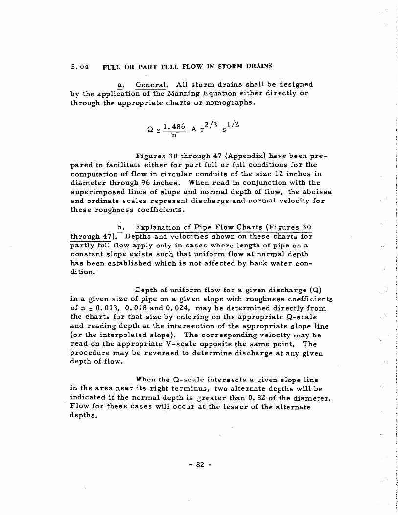
5.04 FULL OR PART FULL FLOW IN STORM DRAINS
a. General. All storm drains shall be designed by the application of the Manning Equation either directly or through the appropriate charts or nomographs.
Q: 1.486 A r2/3 sl/2 n
Figures 30 through 47 (Appendix) have been prepared to facilitate either for part full or full conditions for the computation of flow in circular conduits of the size 12 inches in diameter through 96 inches. When read in conjunction with the superimposed lines of slope and normal depth of flow, the abcissa and ordinate scales represent discharge and normal velocity for these roughness coefficients.
b. Explanation of Pipe Flow Charts (Figures 30 through 4 7). Depths and velocities shown on these charts for partly full flow apply only in cases where length of pipe on a constant slope exists such that uniform flow at normal depth has been established which is not affected by back water condition.
Depth of uniform flow for a given discharge (Q) in a given size of pipe on a given slope with roughness coefficients of n = O. 013, O. 018 and O. 024, may be determined directly from the charts for that size by entering on the appropriate Q-scale and reading depth at the intersection of the appropriate slope line (or the interpolated slope). The corresponding velocity may be read on the appropriate V-scale opposite the same point. The procedure may be reversed to determine discharge at any given depth of flow.
When the Q-scale intersects a given slope line in the area near its right terminus, two alternate depths will be indicated if the normal depth is greater than O. 82 of the diameter. Flow for these cases will occur at the lesser of the alternate depths.
- 82 -

For pipe roughness coefficients other than those shown on the charts, enter the chart on the inner scale n : O. 013 with a value of design (Q) times proposed (n} divided by O. 013 to determine depth and velocity. Read directly from the chart at the pipe slope line and obtain velocity by dividing the value read on the V-scale for n: O. 013 by the same ratio (n) divided by O. 013,
The maximum rate of uniform flow discharge of a:ny circular conduit on a given slope, not flowing under pres sure, will occur with 'the depth of flow of O. 94 diameter. Therefore, to determine the maximum capacity of a pipe on a given slope not flowing under pressure, read the Q-scale for the appropriate value of "n" at the maximum value reached by the sharply curved slope line. Interpolated slope lines follow the same pattern as the designated lines.
When the Q-scale passes to the right of the sharply curved slope line for a given pipe slope, the pipe will flow full and under pressure. For this case, the charts may be used to determine the slope qf the hydraulic gradient and energy lines which are parallel when the pipe flows full. The slope is the frictional slope, or the rate at which energy is lost by resistance to flow. Enter the chart with rate of flow or an adjusted rate of flow for the appropriate "n" value, and intersect the line at full depth equal to the pipe diameter, reading the frictional slope by interpolation on the slope scale. The discharge capacity for a pipe flowing full with a given frictional gradient may be found by reading the discharge at the proper slope point along the line for depth equal to the pipe diameter. Regardless of the roughness value the critical depth for a given discharge is obtained by interpolation from the depth lines at the point where the Q-scale for n = O. 013 and the critical depth curve intersect. Critical velocity is the reading on the V-scale for n = O. 013 for this same point. Critical depths greater than that represented by the last depth line of the charts just less than a diameter have little significance since wave action may intermittently fill the pipe.
Critic_al slopes will ·vary with the roughness of the pipe. When n : O. 013, the critical slope is read corresponding to the critical depth point as described above. To determine the critical slope for values of roughness coefficient other than O. 013, it is first necessary to determine the critical depth. The critical
- 83 -

slope is then interpolated from the slope lines at the intersection of this depth with the Q-scale value for the appropriate "n", or with an adjusted value of Q-scale value for "n" values other than shown on the charts.
5. 05 HYDRAULIC GHADIENT AND PROFILE OF STOUM DRAIN
In storm drain systems flowing full, all losses of energy through resistance of flow in pipes, by changes of momentum or by interference with flow patterns at junctions, must be accounted for by the accumulative head losses along the system from its initial upstream inlet to its outlet. The purpose of accurate determinations of head losses at junctions is to include these values in a progressive calculation of the hydraulic gradient along the storm drain system, In this way, it is possible to determine the water surface elevation which will exist at each structure. The rate of loss of energy through the storm drain system shall be represented by the hydraulic grade line, since the hydraulic grade line measures the pressure head available at any given point within the system.
The hydraulic grade line shall be established for all storm drainage design. In open channels, the water surface itself is the hydraulic grade line, Th.e hydraulic grade line is often controlled by the conditions of the sewer outfall; therefore, the elevation of the tailwater pool must be known. The hydraulic gradient is constructed upstream from the outlet, taking into account all of the head losses .that may occur along the line,
The friction head loss shall be determined by direct application of Manning's Equation or by appropriate nomographs as discussed in Paragraph 5. 03. Minor losses due to turbulence at structures shall be determined by the procedure of Paragraph 5. 08.
The hydraulic grade line shall in no case be closer to the surface of the ground or street than 2 feet. Allowance of head must be provided for at some future date if the proposed storm drainage system is to be ·extended.
- 84 -

5. 06 MANHOLES
a. General. All manholes shall be constructed in accordance with the Standard Details unless otherwise instructed by the City Engineer. The following conditions shall govern the use of the various types of manholes.
b. Types of Manholes
(1) Standard Manhole Types B-1, B-2, B-3 andB-4
(a) Maximum permissible depth - 12 1 (from ground to top of pipe).
(b) Minimum permissible depth ~ 4 1 (from ground to top of pipe).
(c) For pipes 36 inches in diameter and smaller use 4'-0" diameter manhole (straight run). Where manhole is used for junction of three or more lines (36" and smaller) use 5'-0" diameter manhole.
(d) For pipes 39" - 48" in diameter use ' 5' -0" diameter manhole (straight run). Where manhole is used for junction of three or more lines (48" and smaller) use 6 1 -0 11 diameter manhole.
(2) Standard Manhole Types T-1, T-2, T-3 and T-4
Sarne provisions as for Type B manholes.
(3) Standard Manhole Types P-1 and P-2
(a) Minimum permissible depth 12 1 (from ground to top of box) unless pipe size exceeds 48" in diameter.
(b) For pipes 54" in diameter and larger,
- 85 -

(4) Standard Manhole Type C
For any manhole condition where depth is less than 4'-0" (from ground surface to outside top of pipe).
c. Location. Manholes shall be located at intervals not to exceed 600 feet for pipe 24 inches in diameter or smaller. Manholes shall preferably be located at street intersections, sewer junctions, changes of grade and changes of alignment.
Manholes for sewers greater than 24 inches in diameter shall be located at points where design indicates entrance into the sewer is desirable; however, in no case should the distance between openings or entrances be greater than 1, ZOO feet.
5. 07 PIPE CONNECTIONS
Prefabricated wye and tee connections are usually available up to and including 24 11 x 24". Connections larger than 24-inches will be made by field connections. This recommendation is based primarily on the fact that field connections are more easily fitted to a given alignment than are precast connections. Regardless of the amount of care exercised by the Contractor in laying the pipe, gainage in footage invariably throws precast connections slightly out of alignment - this error increases in magnitude as the size of pipe increases ..
5. 08 MINOR HEAD LOSSES AT STRUCTURES
The following head losses at structures shall be determined for inlets, manholes, wye branches or bends in the design of closed conduits. See Figures 20 and Zl for details of each case. Minimum head loss used at any structure shall be O. 10 foot.
The basic equation for most cases, where there is both upstream and downstream velocity, takes the form as set forth below with the various conditions of the coefficient "K·" shown in Table 8. J
- 86 -

v 2 2
h· = J zg
hj = Junction or structure head loss in feet.
v 1 = Velocity in upstream pipe inf. p. s.
v 2 = Velocity in downstream pipe inf. p. s,
Kj : Junction or structure coefficient of loss.
In the case where the inlet or manhole is at the very beginning of a line or the line is laid with bends or on a curve, the equation becomes the following without any velocity of approach.
v 2 hJ.: K
1- _z_
Zg
- 87 -

Case No.
I
II
III
IV
v
VI
VII
VIII
Reference Figure
20
20
20
20
21
21
21
21
TABLE 8
JUNCTION OR STRUCTURE
COEFFICIENT OF LOSS
Description of Condition
Inlet on Main Line
Inlet on Main Line with Branch Lateral
Manhole on Main Line with 45° Branch Lateral
Manhole on Main Line with 90° Branch L<1;teral
45° Wye Connection or cut-in
Inlet or. Manhole at Beginning of line
Conduit on Curves for 90° * Curve radius = diameter Curve radius : (2 to 8) diameter Curve radius : (8 to 20) diameter
Bends where radius is equal to diameter
90° Bend 60° Bend 45° Bend 22-1/2° Bend
Manhole on line with· 60° Lateral
Manhole on line with 22-1/2° Lateral
Coefficient
Kj
o. 50
0.25
0.50
0.25
0.75
I. 25
0.50 0.25 o. 40
0.50 0.43 0.35 0.20
0.35
o. 75
*Where bends other than 90° are used, the 90° bend ·Coefficient can be used with the following percentage factor applied:
60° Bend - 85%; 45° Bend - 70%; 22-1/2° Bend - 40%
- 88 -

..
t------t•J--=---~ ~ __ ' " -
------ ----------- -- =-------
o.~/ / PLAN
o,
SECTION
CASE I
NOTE: For Any Type of Inlet.
2 2 v2 · 0.5v1
h· ' -- -J 2 g 2 g
a.;/ PLAN
v22 0.25\11
2
h- '----) 2g 2g
SECTION
CASE Il
INLET ON MAIN LINE INLET ON MAIN LINE WITH BRANCH LATERAL
NOTE: v 2 035v 2 60° Lateral h· = - 2- - -
2 - 1
• J 2g g PLAN
v 2 0.75v 2 22Y2°Lateral h· = - 2
-----1
J 2 g 2g
SECTION
CASE m
"' 0
PLAN
SECTION
CASE Ill: MANHOLE ON MAIN LINE
WITH 45° BRANCH LATERAL MANHOLE ON MAIN LINE
WITH 90° BRANCH LATERAL
MINOR HEAD LOSSES DUE TO TURBULENCE AT STRUCTURES
- 89 - FIGURE 20

'{.;.:;,...;~=F=='I o ,.v2 -PLAN --- v
22 0.75v1
2 hi (ct t. Conn.)'· 2 - -2-__ hJL g g
SECTION
CASE Y.
45° WYE CONNECTION
OR CUT IN
' I I
14='F''I- _f.L_ -I I
I ' : rn I '
I .J
~I I
CASE JZll
Qz,vz -
CONDUIT ON 90° CURVES*
NOTE: Head loss applied at P.C. for length of curve.
2
Radius= Dia. of Pipe hj= 0.50 * 2
Radius' (2-8) Dia. of Pipe hi' 0,25 fg 2
Rodiuso(B-20) Dia. of Pipe hj'0.40 ;~ Rodi us= Gre.oter than 20 Dia. of Pipe hf:O
twhen curves other than 90°ore used, apply the following factors to 90°cur"v,s. · 60°curve 85°/0
45°curve 70°/0
~,J mt:::::r::::~ ~ PLAN
SECTION
CASE~
INLET OR MANHOLE AT
BEGINNING OF LINE
CASE :mII
BENDS WHERE RADIUS IS
EQUAL TO DIAMETER OF PIPE
NOTE: Head loss applied at beglning of bend v,Z
90° Bend h· oO 50 -J • 2g
v 2 60°Bend hj'0.43 ~
v,Z 45°Bend hj'0.35
29 2
22 V2° Bend hj'0.20 ;~
22 Y2°curve 40°/0 MINOR HEAD LOSSES DUE TO
TURBULENCE AT STRUCTURES
- 90 - FIGURE 21
I

I
5, 09 UTILITIES
a. General, In the design of a storm drainage system, the -engineer is frequently confronted with the problem of intersections between the proposed storm drain and existing utilities such as water, gas and sanitary sewer lines,
b. Water Lines, All existing water lines in the immediate vicinity of the proposed storm drains shall be clearly indicated on both the plan and profile sheets. When design clearly indicates that an intersection of the storm drain line and the water main exists and the proposed storm drain cannot be economically relocated, then the existing water line shall be adjusted, The existing water main may be adjusted in alignment and elevation depending upon the size! type of pipe, and other factors. The City Engineer shall be notified before the final storm sewer grade is'laid where adjustments of water lines 12-inches and larger are required,
c. Sanitary Sewers. All existing or proposed sanitary sewers in the immediate vicinity of the proposed storm drains shall be clearly indicated on both plan and profile sheets. When design clearly indicates that an intersection of the storm drain line and the sanitary sewer exist and the proposed storm drain cannot be economically relocated, then the existing sanitary sewer shall be adjusted by relocation, Inverted siphons shall be used only when authorized by the City Engineer and the siphons shall be constructed of cast iron pipe in accordance with standard detail. All trench crossings for sanitary sewers shall be replaced with cast iron pipe in accordance with the standard detail.
d, Gas Lines and Other Utilities. All existing gas lines and other utilities in the immediate vicinity of the proposed storm drain shall be clearly indicated on both the plan and profile sheets.
Gas lines and other utilities, not controlled by elevation, shall be adjusted when the design clearly indicates that an intersection of the storm drain line and the utility exists and the proposed storm drain cannot be economically relocated. The City Engineer shall be notified when such design is contemplated and approval secured before proceeding with design.
- 91 -

- 92 -

SECTION VI
DESIGN OF CLOSED STORM DRAINAGE SYSTEM
6.01 GENERAL
All storm drains shall be designed by the application of the Manning Equation either directly or through appropriate charts or nomographs. In the preparation of hydraulic designs, a thorough investigation shall be made of all existing structures and their performance on the waterway in question.
An example of the use of the method used in the manual for the design of a storm drainage system is outlined in Paragraphs 6. 03 and 6. 04 and shown on Computation Sheet No. 7 and Drawings 1 to 5 in the Appendix of this manual. The design theory has been presented in the preceding sections with their corresponding tables and graphs of information,
6. 02 PRELIMINARY DESIGN CONSIDERATIONS
.!!:.· Prepare a drainage map of the entire area to be drained by proposed improvements. Contour maps serve as excellent drainage area maps, when supplemented by field reconnaissance. (Scale 1" - 200 1). See Drawing No. 1 in the Appendix of this manual.
b. Make a tentative layout of the proposed storm drainage system, locating all inlets, manholes, mains, laterals, ditches, culverts, etc.
c. Outline the drainage area for each inlet in accordance with present and future street development.
d. Indicate on each drainage area the code identification number, the amount of area, the direction of surface runoff by small arrows, and the coefficient of runoff for the area.
e. Show all existing underground utilities.
- 93 -

f.. Establish design rainfall frequency.
&.• Establish minimmn inlet time of concentration.
:J!• Establish the typical cross section of each street.
i. Establish permissible spread of water on all streets within the drainage area,
6. 03 RUNOFF COMPUTATIONS
The runoffs are shown on the Storm Drain Computation Sheet No. 7 at the end of this section. The first 15 columns of the computation sheet cover the tabulation for runoff computations.
Colmnn l
Colmnn 2
Colmnn 3
Enter the storm drain inlet point nmnber. Design should start at the farthest upstream point.
Enter the storm drain inlet point nmnber of inl.et point immediately downstream. In nmnbering inlets and manholes, it is customary to start numbering inlets and manholes at the beginning of the storm drainage system, proceeding upstream. In order to facilitate the filing and identification of material covering various elements of the storm drainage system, the code identification procedure shown in Section 1. 04 shall be used.
Enter the distance (in feet) between storm drain inlet point shown in Column l and 2. Column l stationing minus Column 2 stationing.
- 94 -

Column 4
Column 5
Column 6
Column 7
Column 8
Column 9
Column 10
Column 11
Column 12
Column 13
Record the identification code number of each different drainage area to correspond to the numbers shown on the drainage area map.
Record the area in acres for each of the individual areas of Column 4.
Record the total drainage area in acres within the system corresponding to storm drain inlet point shown in Column 1.
Record the coefficient of runoff "C 11
for each drainage area shown in Column S.
Multiply Column 5 by Column 7 for each area.
Determine the total "CA 11 for the drainage system corresponding to the inlet or manhole shown in Column 1.
Determine inlet time of concentration (See Figure 2 and Table 2).
Determine flow time in sewer in minutes. The flow time in sewer is equal to the length from Column 3 divided by 60 times the velocity of flow through the sewer.
Total time of concentration in minutes. Column 10 plus Column 11.
De~ign frequency established by Design Criteria from Table 4.
- 95 -

6,04
Column 14
Column 15
Intensity of rainfall in inches per hour corresponding to time of concentration shown in Column 12. Use Figure 3, Rainfall Intensity-Duration-Frequency Curves.
D.esign Discharge or Runoff inc. f. s. Column 9 times Column 14,
HYDRAULIC DESIGN
After the computation of the quantity of storm runoff entering each inlet, the sfae and gradient of pipe required to carry off the design storm are determined. It should be bor·ne in mind that the quantity of flow to be carried by any particular section of storm drain is not the sum of the inlet design quantities of all inlets above that section of pipe, but is less than the straight total. This situation is due to the fact that as the time of concentration increases the rainfall intensity decreases. Columns 16 through 29 of the computation sheet cover the minimum necessary hydraulic requirements to establish the hydraulic grade line for a storm drain and is shown at the end of this section,
Column 16
Column 17
I
The size of pipe is chosen in such a manner that the pipe when, flowing full, will carry an amount of flow equal to or greater than the computed discharge with a desirable velocity.
The slope of the frictional gradient (hydraulic gradient) is chosen so that the pipe when flowing full, will carry an amount of flow equal to or greater than the computed discharge, The pipe shall be constructed on a grade such that the inside crown of the pipe coincides with hydraulic gradient or is below the developed hydraulic gradient when flowing full.
- 96 -

Column 18 and 19
Column 20
Column 21
Column 22
Column 23
Column 24
Column 25
Column 26
Column 27
Record the hydraulic gradient elevations at the upstream end and downstream end of pipe section in question. The elevation of the hydraulic gradient of the upstream end of pipe is equal to the elevation of the downstream (hydraulic gradient) plus the product of Column 3 and Column 17.
Velocity of flow in incoming pipe (main line) at junction, inlet or manhole at design point. (Column 1).
Velocity of flow in outgoing pipe (main line) at junction, inlet or manhole at design point. (Column 1).
Velocity head loss for outgoing velocity (main line) at junction, inlet or manhole at design point (Column l) from Table 30.
Velocity head loss for incoming velocity (main line) at junction, inlet or manhole at design point
·(Column 1) from Table 30,
Head loss coefficient "Kj"• at junction, inlet or manhole at design point from Table 8 or Figure 20 and 21.
Multiply Column 23 by Column 24.
Column 22 minus Column 25.
Column 18 plus Column 26.
- 97 -

Column 28
Column 29
Invert elevation at design point for incoming pipe.
Invert elevation at design poi~ for outgoing pipe.
- 98 -

BY 11u:;1. COMPUTATION SHEET NO. 7 LOCATION 17"-,,s1: FROM /5,th..4Y<'!T0 /7".;, Av~
OATE /Vo;: 1958
HYDRAULIC COMPUTATIONS FOR STORM DRAINS MAJOR WATERSHED AA
CK'D. CONTRACT OR FILE NO. ,4,. ,44~/r.~c1
DATE 'A4!• .. n" LINE = 0.013
.... ELEV. OF INVERT MANHOLE
c~ ...J~ HYDRAULIC ;;r; "' DRAINAGE
§ !· ...J ,..
~ GRADIENT HEAD LOSS AT CHANGE IN SECTION "' ir ~ AT DESIGN POINT NOTES OR ~ ~ TIME OF CONCENTRATION ,.. 15 .. AREA zU .... a: "' Q. ELEVATIONS :r z IS (COL. I) INLET Zo ...J - (!) z in .... It' ~ !z "' .. ~ ~c( - "' ... u "- G: (!) <..> "' - u "' ::> fi ~p 1±: : :IE u "' 0 01-W -+ ~ g,_ INCfalENT AREA ~:
o _u WO ...J "' ~ ::C_ K1v1
2 -' "'m INCOMI ... ---FROM TO TOTAL ~ 15 .... - INLET FLOW TIME TOTAL ow ~ WN ...J ~$1 UP DOWN v, v, ~ ~-: u a: i5 "' - "' "- $ Kj hj
Ii g DE"•GN I! z w AREA u ~ TIME IN SEWER TIME "- "' STREAM STREAM INFLOW OUTFLOW 2g 2g 29 PIPE PIPE ill "' ...J NQ AREA
POINT :IE~
FT. ACRES ACRES MIN. MIN. MIN. YEARS IN/HR. C.F.S. INCHES Fi:/FT. FT. M.S.L FT. M.S.L. FT./SEC. FT/SEC. FT. FT. FT. FT. FT. M.S.L. FT.M.S.L . FT.M.S.L
I 2 3 4 5 6 7 8 9 10 II 12 13 14 15 16 17 18 19 20 21 22 23 24 25 26 27 28 29
I-cG MH.-c2 24' A4c7 2.54 0.35 0.1!9 /5 "'--' /5 2 3. 7t:J .5 .' •. /2. Lo/<-"ra/
I-a 7 tYH-c2 24' A4cb 4.03 tJ..!J§ ~ /5 ~ 15 z 3 ?t:J 5£ IZ La 1-ero/
Mlt-c2 .r-c~
650' tii.57 6.57 2.30 230 ./\_; 15 2 3.70 8.50 21 tJ.OtJZ ..... .%7.Jt:. S~~I -"---- 3.S 0.19 ~ '/.25 0.24 a,E>4 3<.7.60 ..-,__, 3G4,<:.0 Mt7/·n r-a.5 .--._,
I-c4 ,y,,,,,, 24' A4c4 z. 38 0.40 0.95 /5' /""\.._., 15 .? 3. 70 .•. . /Z 36.?.ZS Loi-era/ . .
.
I-as Moin 24' A4c5 L!f_ 0.40 I.lo /5' > ....,__ /5 2 3.70 . IC' 3<:.2.2.5 Laferol
I-c4 lfH-cl _,5 5.13 //.?O E'.05 .¢.3.5 ...,__. !§5o'-f-6ox 8. G • 3.1 /8.1 2 3.4-0 /.f,8 ?4- tJ.0043 ~i;-S.4G %5.3/ .!l.5 4.7 0.34- a;~ 0.5& 0./0 0.15 ~C5,c;/ ·Jr;.?. 00 ~6{.0,0 ,ff,.f/N r-c5 I-c3 MH-d 5t.:i' A4c!I ~ 0.40 !:!!§.. ,?o'
...,, 20 z. 325 ;Z X?.10 La.l~ro/
Mii-ci I-cl ..,. __ ·9 (;/2' P,<;;,5 /4.35 I. Or;; .5.41 .......... 35'.f,:0,,-4 7 :a/ 18.&' .? 3.40 IS.4 .?4 0.00~2 $<:.4. '13 3i:.o.e1 4.7 .5.9 a.s4 ".:$'1 o..so "-17 "·-'? .1i;s. 'I !1'1.60 $<:.!.c;o M,,,;., •. '
I·a/ Mo/n 24 A4cl 3.69 0.35 /.29 /5 /"'....- /5 2 3.70 /,/? 3-5418 Lal,,.ra/
J"·c2 Ma.1n 24" A.fc2 2.43 0.4.5 /. 10 /5 ....--__.. 15 2 3.70 /Z }58./f, Laf'",,..,..,.; I-cl MH-.,3 t;;!J' G.12 20.47 2.39 7.80 G12 ~c;o,.-sr:/. 7 /.9 'f 2 .3?5 ..?.5.4 30 tJ.t?tJ.53 3t:.0.74 3t:.1150 5.9 S.2 a42 t:J.54 tl 50 OZ7 0.15 .!J(;/1d9 $57.93 -'5743 /'4'4/;, r.,.z ------
REMARKS, SKETCHES AN!:> C0MPUTATl0NS
/\/./,:
-99-

SECTION VII
FLOW IN DITCHES AND CHANNELS
• 7. 0 l GENERAL
Open ditches and channels shall be used for collecting or concentrating storm runoff and drainage outlets where pipe lines or conduits cannot be justified on the basis of such factors as initial cost, maintenance cost, serviceability, health and safety. There should be nounprotected deep ditches or channels and steep side slopes adjacent to roads, streets, schools, parks, or other areas subje.ct to frequent use, In urban development, only enough ditches to supplement the pipe system should be provided. The City Engineer should be consulted when extensive ditch or channel work is planned.
7.02 CHANNEL DISCHARGE
Careful attention must be given t6 the design of drainage ditches to assure adequate capacity and minimum maintenance to overcome the result of erosion, silting, sloughing of banks or similar occurrences. The hydraulic characteristics of the ditches and channels shall be determined by the Manning formula.
Q= 1.486 'A r2/3 ll ,_I
1/2 s
Q =Total discharge inc. f, s.
n =Coefficient of roughness
A= Cross-section area of channel in sq. ft,
r =Hydraulic radius of channel in feet.
s =Slope of the frictional gradient in feet.
- 101 -

7.03 GRADIENTS
Ditches should have trapezoidal sections and adequate waterway areas to taR:e care of uncertainties in runoff estimates, changes in channel coefficients, channel obstructions and silt accumulations.
Where practicable, unpaved ditches should have sufficient gradient, depending upon the type of soil, to provide velocities that will be self-cleaning but will not be so great as to create erosion. Manning roughness factors and maximum permissible velocities are shown in Table 9. A minimum of horizontal curves or changes in alignment is desirable. Paved ditches, drop structures, ditch checks or paved spillways may be required to control erosion that results from the high velocities of large volumes of water on steep grades.
TABLE 9
MINIMUM ROUGHNESS COEFFICIENTS AND MAXIMUM PERMISSIBLE VELOCITIES
FOR CHANNELS
Coefficient of Max. Permissible Channel Description Roughness ''n II Mean Velocity fps
Vegetated Channels
Clays (Bermuda Grass) 0.035 5 to 8 Sandy and Silty Soils
(Bermuda Grass) 0.035 3 to 5
Non-vegetated Channels
Concrete lined channels o. 015 15 Riprap (broken concrete) o. 030 15 Natural earth channels
without vegetation: Sandy Soils o. 030 l.5to2.5 Silts o. 030 0, 7 to 1. 5 Sandy Silts o. 030 2, 5 to 3. 0 Clays o. 030 3,0 to 5,0 Coarse gravels o. 030 5. 0 to s.o Shale o. 030 6.0 to 10,0 Rock 0,025 15
- 102 -

7.04 SIDE SLOPES
Also to prevent erosion, ditches and channels should have smooth sloping sides, Where it is economically feasible to develop and maintain turfed side slopes, these slopes should not be steeper than three horizontal to one vertical.
7.05 SEDIMENTATION
To prevent sedimentation in wide ditches or channels with flat side slopes and low velocities, a secondary or pilot channel may be required to increase the channel velocity during low flows.
7. 06 BRANCHES
Branches should join .the main ditch or channel at an acute angle to avoid de position of debris at the junction and erosion of the opposite bank.
7. 07 DITCH LINING
.e_. Turf, Earth channels normally require some type of lining, such as strong turf which is not susceptible to rank growth. Bermuda grass is ideally suited for turfing and should be used unless otherwise instructed. In particularly erosive soils, special methods may be necessary to establish the turf quickly or to provide supplemental protection, by mulching or similar rneanso
Erosion frequently becomes a problem involving ditches, especially on steep slopes, prior to the establishment of a vigorous turf. Should erosion be so rapid as to render turf establishment impossible, other erosion control measures should be taken.
b. Paved Lining. Lining or partial lining may be required where erosion may be caused by soil conditions or by high velocities from comparatively steep gradients, excessive
- 103 -

flow of water, steep side slopes, changes in direction of channel, etc. Ditch lining should be utilized only where clearly justified for health and safety or to prevent excessive maintenance costs. The ditch lining may be of plain or reinforced concrete, bituminous materials, or plain or grouted riprap.
- 104 -
SECTION VIII
DESIGN OF CULVERTS
8. 01 GENERAL
The function of.a drainage culvert is to pass storm flow from the upstream side of a highway, road or railroad to the downstream side without causing excessive backwater head and without creating excessive downstream velocities. The designer shall keep the losses of head and discharge velocities within safe limits while selecting the most economical structure that will provide the satisfactory service.
8. 02 QUANTITY OF FLOW
The quantity of flow shall be determined by the Rational Method as set forth in Section II of this manual. Culverts in size up to and including an 84-inch diameter pipe shall be designed on a frequency of 10 years while structures larger shall be designed on a 25-year frequency. All culverts shall be checked for a 50-year frequency to determine the upstream backwqter conditions as well as downstream velocities and flooding conditions. (See Section II).
For areas where the proposed culvert or culverts will eventually become part of the\palrni.ed" storm drainage system, the alignment, location and grade ··must be predetermined to insure the most economical development of the planned drainage system. The designer shall consult the "Master Drainage Plan" before proceeding with the design of any storm drainage improvement. In the event the particular watershed or waterway is not covered by the "Master Storm Drainage Plan", then the designer shall proceed with the design from the nearest downstream control, as instructed by the City Engineer, keeping in mind the future expansion of the drainage improvements.
- 105 -

8. 03 HEADWALLS AND ENDW ALLS
a. General. The normal functions of properly designed deadwalls and endwalls are to anchor the storm drain or culvert pipe, to prevent disjointing due to lateral pressures, to control erosion and scour resulting from excessive velocities and turbulence and to prevent adjacent soil from sloughing in to the waterway opening. All headwalls shall be constructed of reinforced concrete and may be of either straight parallel headwalls, flared headwalls or warped headwalls with or without aprons and cutoff walls as may be required by local conditions. Definite design criteria applicable to all conditions cannot be formulated, but the following conditions should dictate the requirements for most headwall and endwall installations.
b. Conditions at Entrance. In considering the designs for entrance-conditions for culverts, it is important to remember
·that the operating characteristics of a culvert may· be completely changed by the shape or condition at the inlet or entrance. Therefore, all culverts _shall be provided with headwalls of either standard or special design as instructed by the City Engineer. The entrance head losses marbe determined in terms of the following equation.
he: Ke(~-~) 2g 2g
he : Entrance head loss in feet.
v 2 : Velocity of flow in culvert.
vl : Velocity of approach inf. p.·s.
Ke : Entrance loss coefficient as shown in Table 1 o.
- 106 -

TABLE 10
VALUES OF ENTRANCE LOSS COEFFICIENTS "Ke"
Type of Structure and Entrance Design Value of Ke
Concrete Pipe {with Concrete Headwall)
Groove End Upstream o. 3
Square End. Upstream 0.5
Round Entrance 0. 2 {4" Radius)
Corrugated Metal Pipe
Square End Upstream 0.5
Round Entrance o. 2 {4" Radius)
Concrete Box Culvert
Square End Upstream 0.5
Round Entrance O. 2 '(4 11 Radius)
In order to compensate for the retarding effect on the velocity of approach in channels produced by the creation of the headwater pools at culvert entrances, the velocity of approach shall be reduced by the factors as shown in Table 11.
- 107 -

TABLE 11
REDUCTION FACTORS FOR VELOCITY OF APPROACH
Limits of Velocity of Approach
"v1 JI
(f.p.s.)
0 - 6
Above 6
Above 6
Description of Conditions
For all culverts
For culverts where the alignment of the approach channel is good and where a headwater pool is permissible within the rightof-way
For culverts where the alignment of the approach channel is good, where the channel slopes have been lined and where a limited backwater pool is permissible within the right-of-way
c. Installations.
Reduction Factor for
Velocity of Approach
0
o. 5
1. 0
(1) Parallel Headwall and End wall. Parallel or straight headwalls and endwalls should be used where approach velocities are low (below 6 f.p. s. ), where backwater pools may be formed, where approach channels are undefined, where.unlimited right-of-way is available, and where no downstream channel protection is required.
(2) Flared Headwalls and Endwalls. Flared head• walls and end walls should be used for a well defined channel, where moderate approach velocities ( 6 to 10 f, P• s.) and medium amounts of debris exist. The wings of flared walls should be located with respect to the axis of the approach channel velocity instead of the culvert axis
- 108 -

(3) Warped Headwalls and Endwalls. Warped headwalls should be used for a well defined channel to obtain a gradual transition with minimum head loss (concrete lined), where moderate to high approach velocities (B to 20 f. p. s.) and medium amounts of debris exist. These headwalls are effective with drop down aprons to accelerate flow through culvert, and are effective endwalls for transition flow from closed conduit flow to open channel flow. This type of headwall should only be used for large drainage installations with limited right-of-way.
B.04 CULVERT DISCHARGE VELOCITIES
The velocity of discharge from culverts should be limited as shown in Table 12. Consideration must be given to the effect of high velocities, eddies or other turbulence on the natural channel., downstream property and roadway embankment.
TABLE 12
CULVERT DISCHARGE - VELOCITY LIMITATIONS
Culvert Discharging
On To
Earth
Sod Earth
Paved or Riprap Apron
Shale
Rock
- 109 -
Maximum Allowable
Velocity (f. p. s.)
6 f.p.s.
B f.p. s.
lSf.p.s.
10 f. p. s.
15f.p.s.
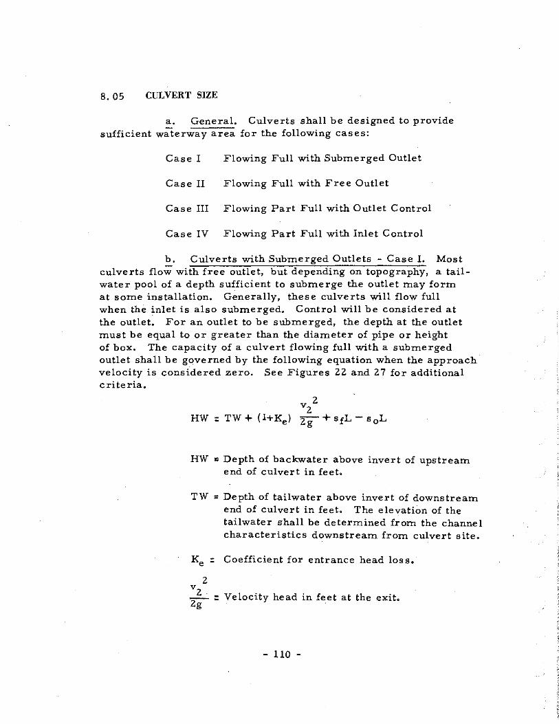
8. 05 CULVERT SIZE
a. General. Culverts shall be designed to provide sufficient waterway area for the following cases:
Case I Flowing Full with Submerged Outlet
Case II Flowing Full with Free Outlet
Case III Flowing Part Full with Outlet Control
Case IV Flowing Part Full with Inlet Control
b. Culverts with Submerged Outlets - Case I. Most culverts flo;; with free outlet, but depending on topography, a tailwater pool of a depth sufficient to submerge the outlet may form at some installation. Generally, these culverts will flow full when the inlet is also submerged. Control will be considered at the outlet. For an outlet to be submerged, the depth at the outlet must be equal to or greater than the diameter of pipe or height of box. The capacity of a culvert flowing full with a submerged outlet shall be governed by the following equation when the approach· velocity is considered zero. See Figures 22 and 2 7 for additional criteria.
HW : TW + (l+Ke)
v 2 2
2g +sfL-s 0 L
HW = Depth of backwater above invert of upstream end of culvert in feet.
TW = Depth of tailwater above invert of downstream end of culvert in feet. The elevation of the tailwater shall be determined from the channel characteristics downstream from culvert site.
Ke : Coefficient for entrance head loss.
2 v2 zg- : Velocity head in feet at the exit,
- 110 -

sf : Slope of frictional gradient in feet per foot,
s 0 : Slope of culvert grade in feet per foot.
L = Length of culvert in feet.
Submergence of the outlet does not necessarily insure full flow. Culverts on steep grades may flow partly full to a point inside the pipe. Here, a hyqraulic jump forms because of the submerged outlet. Such type installations provide an excellent way of controlling the downstream velocities as well as keeping the backwater pool to a minimU1ll.
When the approach velocity is greater than zero for submerged outlet culverts, the following equation shall be used:
HW
v 2 l
2g
,,
O'
_v_t) +sfL -2g
Velocity head of approach in feet.
c. Culverts with Free Outlets - Case II. A culvert with a free outfall will flow full when the normal depth of flow through the pipe or box is equal to the diameter of the pipe or height of box, respectively, and the slope of the frictional gradient is equal to the slope of the culvert grade.
The capacity of a culvert flowing full with a free outlet shall be governed by the following equation when the approach velocity is considered zero. For additional criteria see Figures 22 and 27.
HW : D + (l +Ke)
- lil -

HW = Depth of backwater above the invert of upstream end of culvert in feet.
D : Diameter of pipe or height of box in feet.
Ke = Coefficient of entrance head loss.
2 v2 zg-= Velocity head at exit in feet.
When the approach velocity is greater than zero, the following equation shall be used:
2 vl -zg- Velocity head of approach in feet.
d. Capacity of Culvert Flowing Part Full with Outlet Control - Case III. In culvert design, it is generally considered that the head water pool maintains a constant level during the design storm. 1£ this level does not submerge the culvert inlet, the culvert flows part full. To determine the discharge through this culvert, the location of the channel cross section at which critical flow 'occurs must be known. In culvert design, two possibilities for this location are considered, one at or near the outlet and the other near the inlet.
1£ critical flow occurs at the outlet the culvert is said to have "Outlet Control". A culvert flowing part full with outlet control will require the depth of flow in the barrel of the culvert to be greater than critical depth while passing through critical depth at the outlet.
The capacity of a culvert flowing part full with outlet control shall be gover.ned by the following equation when the approach velocity is considered zero. For additional criteria see Figure 23.
- 112 -

HW = Depth of backwater above the invert of the upstream end of culvert in feet.
de = Critical depth of flow in feet.
Ke : Coefficient of entrance head loss.
2 vz 2g" = Velocity head of exit in feet.
Sf " Slope of frictional head loss in ft. per ft.
s 0 = Slope of culvert grade in ft. per ft.
L : Length of culvert in feet.
When approach velocity is greater than zero, the following equation shall be used.
2 vl zg-= Velocity head of approach in feet.
e. Culvert Flow with Inlet Control - Case IV. If critical flow occurs near the inlet, the culvert is said to have 'inlet Control". The maximum discharge through a culvert flowing part full occurs when flow is at critical depth for a given energy head. To assure that flo_w passes through critical depth near the inlet, the culvert must be laid on a slope equal to or greater than critical slope for the design discharge, Placing
- 113 -

culverts which are to flow part full on slopes greater than critical slope will increase the outlet velocities but will not increase the discharge. The discharge is limited by the section near the inlet at which critical flow occurs.
The capacity of a culvert flowing part full with control at the inlet shall be governed by the following equation when the approach velocity is considered zero. For additional criteria, see Figures 23, 28, and 29.
HW : Depth of backwater above the invert of upstream end of culvert in feet.
de : Critical depth of flow in feet.
Ke : Coefficient of entrance head loss.
2 vz Zg : Velocity head at exit in feet.
When approach velocity is greater than zero, the following equation shall be used: ,.
vzz , (vzz viz\
HW: de+ zg-+Ke ~ -"lg) 2
v1 Zg : Velocity head of approach in feet.
- 114 -

v,
3: .... 1
3: J:
v,
"2-----~·· •o D
___..,,__ -- -- -- -- --
L
HW=TWt(ltK0 ) ~~ + 51L-s0 L(Eq.I) When TW>D
v 2.·,. (·v z v2) HW=TW+-'..·+K
8.L-..L tSfL-s
0L (Eq.2)
29,... 2g 2g
sf'.:! so ::sc
dn~D>dc
--
CASE I ~ = o (Eq. J)(lllustroted)
FULL FLOW SUBMERGED OUTLET
L
v 2 HW=Dt(l+K0lfg (Eq.3)
I.; HW=Ot:'..i+KI~_::'.{) (Eq.4)
When Sf::: s0 :5 sc
dn::: D >de
2g s\2g· 29
CASE ll FULL FLOW
Fl'IEE OUTLET
v1 = D ( Eq. 3 )(11 lustrated)
~>O ( Eq.4)
CULVERT FLOW CONDITIONS
- 115 -
FIGURE 22

"' v :r: I
L
CASE m PART FULL FLOW
OUTLET CONTROL
L
, HW' de t(I +Ke)~ (Eq. 7)
y2 y2y2) HW'dc+fg-+i<J.~-fg (Eq.8)
CASE 17
PART FULL FLOW
IN LET CONTROL
sf =:- so!: Sc
v,,o (Eq.5)(111ustrated)
'-'1>0 (Eq.6)
Sf~ So~ Sc v, 'O ( Eq. 7) (Illustrated)
Vr~· 0 {Eq.8)
CULVERT FLOW CONDITIONS
- llfu -
d
-
FIGURE 23
SECTION IX
STRUCTURAL DESIGN OF STORM DRAINS
9. 01 GENERAL
The following criteria for the structural design of storm drains, are based on the assumption that the storm drains will be buried in trenches entirely below the natural ground surface, that the sides of the trench will be virtually vertical below the top of the pipe and will have no flatter slopes than one horizontal to two vertical above the top of the pipe, and that the trench width at the top of the pipe will be relatively narrow. Under these conditions the following trench widths should be used for pipe installations:
12" to 33" diameter pipe, outside diameter of pipe plus 16"
36" diameter pipe and larger, outside diameter of pipe plus 24 11
In the cases where storm drains would be laid in fills that have not become thoroughly compacted, the supporting strength of the pipe shall be determined by the methods outlined in the Iowa State College Bulletin 112, 'The Supporting Strength of Rigid Pipe Culvert"•
9.02 MINIMUM HEIGHT OF FILL
a. Rigid Pipe. The minimum height of fill between the top of a rigid pipe storm drain and the finished grade of any type roadway shall be 2. 00 feet.
b. Flexible Metal Pipe. The minimum height of fill between the top of a flexible metal pipe storm drain and the finished grade of any type of roadway shall be 2. 00 feet.
- 117 -

9. 03 SUPPORTING STRENGTH OF STORM DRAINS
!!:.· Rigid Pipe. The supporting strength of a pipe storm drain depends primarily upon the strength of the pipe itself and the manner in which it is laid in the trench. The following classes of embedment shall be used to yield the factors of safety used in design to provide for uncertainties:
Class "A" Embedment (Figure 24) Load factor 3. 0 Class "B" Embedment (Figure 25) Load factor 1. 9 Class "C" Embedment (Figure 26) Load factor 1. 5
Pipe laid in Class "A" Embedment, illustrated in Figure 24, would support approximately 100 per cent more load than if laid in Class "C" Embedment as illustrated in Figure 26; however, Class "A 11 Embedment shall primarily be used when rock foundations are encountered. Normally, Class "C" Embedment is satisfactory for most foundations. The designer shall thoroughly investigate the soil conditions before selecting the type and class of pipe material.
Figures 24, 25 and 26 set forth the conditions for the use of Reinforced Concrete Pipe (C 76-57) Class II and III. When trench depths exceed those shown on the figures, pipe strength shall then be determined by the methods outlined in the Iowa State College Bulletin 112, "Supporting Strength of Rigid Pipe Culverts"·
b. Flexible Metal Pipe. The supporting strengths for various types and shapes of corrugated metal pipes are shown in Figures 24, 25 and 26, When the depth of cover exceeds that shown in the above mentioned tables, then the supporting strength for flexible pipes shall be determined by the methods outlined in the Iowa College Bulletin 153, "The Structural Design of Flexible Pipe Culverts"· Trench widths shall be the same for flexible pipes as those for rigid pipes.
!:..· Monolithic Concrete Storm Drains. The design of all reinforced concrete culverts, boxes, structures, sewers and appurtenances shall be designed in accordance with the latest addition of American Association of State Highway Officials, "Standard Specifications for Highway Bridges"·
- 118 -

Concrete shall have a minimum compressive strength of 3, 000 p. s. i, at 28 days. The modular ratio used in flexural calculations shall be 10,
All reinforcing steel shall be deformed, new billet, intermediate grade, conforming to the latest American Society of Testing Materials Specifications A-15 and A-305.
Reinforcing steel shall have allowable working stresses of 20, 000 P• s. i. for bars of intermediate and hard grades, 18,000 P• s. i. for bars of structural grade.
- 119 -
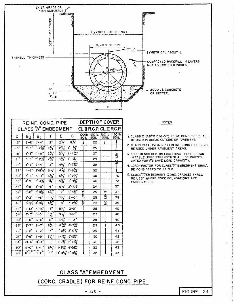
EXIST. GRADE OR _/7 FINISH SUBGRADE/
"' "' > 0 u LL 0
J: ... fl_
"' 0 Be 0 0.D. OF PIPE
'~~~-~"---/~-+ ---::;;;o-.I~,,-,,._ SYMETRICAL ABOUT l
. A ... ,, T<SHELL THICKNESS-------+---+--. .·· .. ·. · ·· ... ~-· ... _ .. ", .
. ·.·
c
REINF. CONG. PIPE DEPTH OF COVER NOTES
CLASS "A" EMBEDMENT CL.II R.C.P. CL.filRC.P.
D Bct Be T E c IOOlb. 1301b. IOOlb. 130 lb. I. CLASS II (ASTM C76-57) REINF. CONC. PIPE SHALL SOIL SOIL SOIL SOIL
12" 2'-s" 1'-4" 2" 27'8 1 11ra" 4 BE USED IN AREAS OUTSIDE OF PAVEMENT.
22
1'-?l'~t 2Y4" 2)18' 1'-17'~' I 2. CLASS m (ASTM C76-57) REINF. CONC. PIPE SHALL 15" 3'-0° 25 BE USED UNDER PAVEMENT AREAS.
IB" 3'-3" 1'-11" 2Y~' 37'~' 1'-4Y4"1 27 ~ 3. FOR TRENCH DEPTHS EXCEEDING THOSE SHOWN
21 11 3'-6" 2'-2Y2 2o/~' 3)/8' 1'-67'4' 29 ~ IN TABLE; PIPE STRENGTH SHALL BE INVEST!-n GATED FOR ITS SAFE LOAD CAPACITY.
24' 3'-s" 21-411 3" 47's" 1'-77'4' 29 'f 4. LOAD-FACTOR FOR CLASS ''A" EMBEDMENT SHALL
27" 4'-2" 2'-9Yi 3 Y4' 4Y8' 1' -117'4' 30 1. BE CONSIDERED TO BE 3.0.
30" 41-6" 3'-1" 3YA" 57'8' 2'-2Y2' 30 76 5. CLASS"A"EMBEDMENT (CONC. CRADLE) SHALL
33" 4'-9" 3'-4Y21 37'4" 5"ta" i-47'~'
BE USED WHERE ROCK FOUNDATIONS ARE 30 72 ENCOUNTERED.
36" 5'-s" 3'-s" 4" sY2' 21-778' 24 37
391t s'-o" 3'-11YZ' 4}'4" 7" 2'-9}4' t: 25 ... 37 = 42
11 6-3" 41-311 4 Y2" 7Y2" 3'-0" - 25 39 _J _J
4511
6'-6Y,' 4'-eY~' 4}~' B" 3!..zYi' 0 25 0 39 z z
49" s'-10" 4 1-1011 5" eY2' 3'-5" 25 40
54" 71-5" s'-s" 5~" g~" 3!..10" 27 40
60° a'-o" s'-o" 6" 10Y201 4 1-3" 2B 40
66'' e'-7" 6 1-711 sY211 11 5/~' 4'-1Y~' 29 40
72" 9'-2" 1'-2" 7" 1'-o!i'S' 5'-01'8' 29 41
78 11 fi-9 11 71-911 7Y2" 1'-17'~' 5'-53'.' 30 42
84" !d-4" s'-4" B" 1'-2o/~' s'-107:; 31 42
90" 11'-o" a'-11" 8 1/21
1':..35''
61-31'8' 32 43
96" 11'-6" 91-611 9" 1'-434 s'-s!f'~' 32 43
CLASS"A"EMBEDMENT
(CONG. CRADLE) FOR REINF. CONG. PIPE
- 120 - I FIGURE 24

EXIST. GROUND OR FINISH SUBGRAOE.
tr w i) (..)
l'; :l: IQ. w 0
Bd' WIDTH OF TRENCH
SYMETRICAL ABOUT t_
T• SHELL THICKNESS ------!----+-..,,. -:::::=-11- COMPACTED BACKFILL IN LAYERS NOT TO EXCEED B INCHES.
D
12"
15"
tB"
21"
24"
27"
30"
33"
36"
39"
42"
45"
48"
54"
so" 66"
12"
74"
84"
90"
96°
REINF. CONC. PIPE
c'
DEPTH OF COVER
SANO CUSHION OR I PART CEMENT TO 12 PARTS AGGREGATE, CONTRACTORS OPTION.
NOTES
CLASS 118 11 EMBEDMENT CL.ll R.C.P. CL.m R.C.P. I. CLASS II (ASTM C 76-57) REINF.
Bd Be 2'-0" 1'-4"
3'-0" 1'-7Y2"
3'-3" 1'-11"
~6" 2'-2Y2'
3'-e" 2'-4"
4'-2" 2'-9Y2'
4'-6" 3'-1"
4-9" 3'-4!f'
5'-0" 3'-s"
e'-o" 3'-11Y2' 61-3" 4'-3"
s'-s" 4'-6)2'
s'-10" 4'-10"
7'-5" 5'-5"
e'-o" s'-011
e'-1" s'-1"
9'-2" 7'-2"
9'-9" 7'-9"
10'-4" a'-4"
11'-o" s'-11"
11'-s" 9'-s"
T E E' c c' IOOlb. 1301b. IOOlb. 1301b. SOIL SOIL SOIL SOIL
2" 2fa" 4fa" I lo/a" 1'-4Y2' t 8 12
21/4" 2Y~' 4°Y8' 1'-1o/~ 1'-7" I- 10 15 = 2Y,:· 3o/8' 5}~' l'-4¥.; 1'-9}'~' .J II 17
2t4" 3~a" 518' 1'-6% 2'-0" z 12 f- 17 ::=
3" 4o/8' s~e· 1 1-7o/~' 2·-2rs· I 13 :::; 18
3!f4" 4y~· 6 /'a" 1'-11,.~· 2'-5" 40 13 z 19
3Y2" 5o/a" 17'~' 2'-2Y~· 2'-7}'~' 35 14 19
33" 518' 17!8' 2'-4"/,; 2'-10" 30 14 f 20
4" 6Y2' BY2' 2'-7Ys' 3'-0'}4' 21 13 41 17
4y~· 7" 9" 2'-Sf~' 31-311
21 13 41 17
4Y2" 1Y2" 9Yi' 31-0" 3'-57'0' 21 14 39 18
4:;4" 8" 10" 3'-2Y~ 3'-a" 21 14 39 18
5" sY2" 10~2· 3'-5" 3'-1072 21 15 38 19
sY211 9 Y2" 11Y2' 3'-10" 4'-3¥2' 23 16 38 20
6" IOY2' 1'-0/'2 4 1-3" 4'-87'8' 23 17 37 21
sY~' 11 o/8" 1'-1o/g" 4'-7~~ 5'-1Y~' 24 17 37 22
7" 1'-05/a" f-21'~' 5-or.· 5~6y~· 24 18 37 23
7Y2" 1'-1 ')'8' 1'-31'.; 5'-53/.i' 5'-11~8' 25 19 37 24
8" 1'-27'~' 1'-4o/8' 5'-1or~ 6'-?o/8' 26 19 37 24
a Yi' l'-31'.;' i'-5o/8" s'-3o/8' 6'-9Ya" 26 20 37 25
9" 1'-47'~' 11-6\" s'-a519· 1!..2y~· 27 21 37 25
CLASS"B''EMBEDMENT
FOR REINFORCED CONCRETE PIPE
- 121 -
CONC. PIPE SHALL BE USED IN AREAS OUTSIDE OF PAVEMENT.
2. CLAssm (ASTM C76-57) REINF. CONC. PIPE SHALL BE USED UNDER PAVEMENT AREAS.
3. FOR TRENCH DEPTHS EXCEEDING THOSE SHOWN IN TABLE; PIPE STRENGTH SHALL BE INVESTIGATED FOR ITS SAFE LOAD CAPACITY.
4. LOAD-FACTOR FOR CLASS"B" EMBEOMENT SHALL BE CONSIDERED TO BE 1.9
5. CLASS"B"EMBEDMENT TO BE USED FOR HARO UNYIELDING FOUNDATION MATERIALS.
FIGURE 25

EXIST. GROUND OR _/ FINISH SUBGRADE. 7 -""!I er
w > 0
" lL 0 r .... a_
~
Bd•WIDTH OF TRENCH
~
T •SHELL THICKNES;:s-------+.----f-.::·:/~:>" ·: ~ ·::.: ·~
j; .... -· p\P~ ·::~
SYMETRICAL ABOUT t.
~ 1-- COMPACTED BACKFILL IN LAYERS \ - NOT TO EXCEED B INCHES.
.. ,.,,,.. /~ ' ··.
DEPT OF EMBEDM-;E~;;i,;..TL-/ ___ ~~~>;ov,~·:: .. :',~ .. ~~~f.j~"J"5."IP.!!i'~!l"lllJef
C - WIDTH OF EMBEDMENT
REINF. CONC. PIPE DEPTH OF COVER NOTES
CLASS"C" EMBEDMENT CL.Il R.C.P. CL.filRC.P. ·~·
D Bct Be T E c 100\b. 130\b. IOOlb. 1301b. SOIL SOIL SOIL SOIL
12" 2'-s" 1'-4" 2" 27'0' 11~8' I. CLASS Il (ASTM C76-57) REINF. CONC. PIPE
13 7 9 SHALL BE USED IN AREAS OUTSIDE OF PAVMT.
15" 3'-0" l'-77'2' 2}'4" 2-r.;· lf-17'4" 15 8 II 2. CLASS m (ASTM C76-57) REINF. CONC. PIPE
!Su 3'-3" 1'-11° 2 Y2" 3ra" 1'-47'~' 17 9 ::;; 12 SHALL BE USED IN UNDER PAVEMENT AREAS.
21" 3'-6fl 2'-2Yr!' 23" 3}911 1'-s34" 18 9 - 13 3. FOR TRENCH DEPTHS EXCEEDING THOSE SHOWN
IN TABLE; PIPE STRENGTH SHALL BE INVEST\-2411 3'-au 2'-411 3" 4o/e" 1'-7o/~' 18 10 z 14 GATED FOR ITS SAFE LOAD CAPACITY.
27'' 4'-211 2'-9Yz' 3y~· 4}'9· 1'-1174' 19 II i4 4. LOAD-FACTOR FOR CLAss"c"EMBEDMENT SHALL BE CONSIDERED TO BE 1.50.
30" 4'-s" 3'-1" 3!;2" s7'a" 2'-2Y2'1 19 II 15 5. CLASS C EM8EDMENT TO BE USED FOR ORDINARY
3311 4'-9" 3
1-4¥2 37'4' sYS' 2'-4"/8' 19 12 45 15 FOUNDATION MATERIALS.
361< s-s" 3'-s" 4" sY2" 2'-7}'8' 15 II 23 14
39" 6'-d' 3'-1tY2 47'4' 7" 2'-91'4' 15 II 23 14
42" 6'-311 4 1-3" 4Y2' 1Y211 3'-011
16 II 24 15
4511 s'-s~· 4-sYi' 43/~' a" 3'-2Y:t 16 II 24 15
48 11 s'-10" 4'-1d' 5" aY£ 31-511 17 12 25 16
5411 7
1-5
11 5'-5" sY2' 9}'2' 3'-1011 18 13 25 17
so" s'-o" s'-011 6" IOYi' 4 1-311 19 14 26 17
66" a'-1 11 61
-711 sY2" t lo/8' 4'-77'8' 19 15 26 18
7211 9~211 7'-2" 7" 1'-0!8' s'-oYS' 20 15 26 19
78" 91-9
11 7'-9° 1Y2" 1'-17'8' 5'-574 21 16 27 19
84" 10'4" a'-4" a" 1·-2~~· s'-1~ 21 17 28 20
90" 11'-o" s' -11" eY~' l'-37'8' 6'·3o/e' 22 17 29 21
96° 11'-6" 9 1-6" 9" 1'-4%; s'-a7'81 23 18 29 21
CLASS"C''EMBEDMENT
FOR REINFORCED CONCRETE PIPE
- lZZ - I FIGURE 26

SECTION X
APPENDIX A
10, 01 REFERENCE SOURCES USED FOR DESIGN CRITERIA
1. Davis, C. V. , Handbook of Applied Hydraulics, McGraw-Hill Book Company, New York, 1952, 2nd Ed.
2. King, H. W. , Handbook of Hydraulics, McGrawHill Book Company, New York, 1954, 4th Ed.
3, Corps of Engineers, ''Drainage and Erosion Control, 11 Civil Works Construction, Part XIII, Chapter 1-4, Supt. of Doc,, Washington, D. C.
4. Corps of Engineers, 11Hydrologic and Hydraulic Analysis, 11 Civil Works Construction, Part CXIV, Chapter 5, Supt. of Doc. , Washington, D. C.
5. U. S. Navy, Storm Drainage Systems, Technical Publication TT-Pw-1, Bureau of Yards and Docks, Washington, D. C. , 1952.
6. U. S. Weather Bureau, Rainfall Intensity-DurationFreguency Curves, Technical Paper No. 25, Supt. of Doc. , Washington, D. C. , Dec., 1955.
7. Texas Highway Department, Rational Design of Culverts and Bridges, Austin, Texas.
8. Texas Highway Department, Storm Sewer Design Manual, Austin, Texas, 1951.
9. Texas Highway Department, Plan Preparation, Book III, Bridge Division, Austin, Texas, December 1952.
10, Johns Hopkins University, The Design of Storm Water Inlets, Department of Sanitary Engineering and Water Resources, Baltimore, Maryland, June 1956.
- 123 -

11, Mavis, F. T., The Hydraulics of Culverts, Engineering Experiment Station Series, Bulletin No. 56, Penn. State College, 193 6.
12, Spangler, M. G., Soil Engineering, International Textbook Company, Scranton, Pa. , 1951.
13, Rational Design Procedure, City of Dallas, Texas.
14. Hydrology Handbook, A.S. C.E., New York, 1949.
- 124 -

SECTION X
APPENDIX B
10. OZ TABLES, FIGURES, CHARTS, NOMOGRAPHS AND COMPUTATION SHEETS
- 125 -

TABLE 13
STANDARD SIZES CIRCULAR SECTIONS (FLOWING FULL)
AND HYDRAULIC ELEMENTS
Shell Wetted Hydraulic R2/3 R4/3 AR2/3 Inside Thickness Perimeter Radius
Diameter (For Cone. Pipe) Area (Feet) (Feet) (Inches) (Inches) (Square Feet) W. P. R
D A rn,L <OQ "t · 5 -5!:.~ 76-, &o 12 -::ioo t,.·rr. 2.00 '), ') ::.) rr o. 79 3. 14 0.250 0.397 0. 158 0. 312
23 7, 15 3 15' ('r.v"t"'\ 2.25 '.J. '.l: . i " 1. 23 3.93 0.313 0.461 0.212 0.566 • • I \) 7, 18 45'0 0'•T. 2.50 Q.003S,,, 1. 77 4.71 0.375 0.520 0.270 b.. 919 ~ ' :::.? ''> i) 21 3 '2.5 rr.r-v-. 2. 75 n.~1~1'~ ~·· 2.41 5.50 0.438 0.576 0.332 1. 385 '\3~!1 24 k,CJO lf'"T"\fY"\ 3.00 1 ' "1· ,'. ,. ' 3. 1:1 6. 28 o. 500 0.630 0.397 1. ~79
I "~ . 27 ~ ~ 5 'fr,('r, 3.25 ;.ae~c: , .. 3.97 7. 07 0.563 0.681 0.465 2. 708 .... = 30 -f 50 ,..,..r, 3.50 4. 9.1 7. 85 0.625 0.731 0.534 3.588 N .\J9 fo (].O!j~~ C' 0-- 0 ~! 33 ?i ~:. s ()-, (('. 3. 75 'J: 1 /)~ . .:.. (1 5. 94 8. 63 0.688 o. 781 0.607 4. 639 1
,DO-'"
.(')17. 36 9.00 ,.,-.,,,, 4.00 'l ' \ ") ( (., 0- 7. 07 9.43 o. 750 0.825 0.681 5. 832
,O<'.o 7. 39 4.25 0.'0I}• 8. 30 10.21 o. 812 0.869 0. 755 7.204 . O(o1o 42 l,OS() ('f_rr. 4.50 (). ! 14· l'r, 9. 62 11. 00 ·o. 875 0.915 0.837 8. 803 .os'?. 45 4. 75 1J, it: I"-" I.l. 04 11. 78 0.937 0.960 0. 911 10. 59 , G57• 48 '0,.0 0 (1-:f-,"'. 5. 00 r'), :i-z rr 12.57 12.57 1.000 1. 000 1. 000 12. 566
5I 5.25 0.; 33 .,, 14. 19 13. 3 5 1. 062 1. 040 1. 074 14. 75 , i::i 4-'I, 54 '. ~ 5 0 p-_ r·· 5.50 0,\3'JOo 15~ 90 14. 14 1. 125 1. 082 1. 170 17.208
60 1500 f,Y K. 6.00 1.:.S'r. 19. 64 15. 71 1. 250 1. 160 1. 347 22. 777 ,Q4.!7· '04:1. 66 :toSO rr :r 6.50 Q.\.~S"f\· 23,76 17.28 1. 375 1. 236 1. 536 29.365
.o:o1· 72 : 860 rn("r~ 7.00 1~i76rr 28.27 18. 85 1.500 1. 310 1. 717 37. 039 .O~~lr 78 1'150 f"'" 7.50 (). ·- c.: ' :11 33. 18 20. 42 1. 625 1. 382 1. 918 45. 859 .<!)37. 84 :_-_100 'f"r """' 8.00 ·).?.'.33 f, 38. 49 21. 99 1. 750 1. 452 2. 109 55. 880
90 L~_So rrrr, 8. 50 '), ('_ : ;. \T 44.18 23.56 1. 875 1. 521 2.320 67. 196 • o?...7 96 '2.A<311 1''' (\", 9. 00 (j. :::. ,._: C"': 50.27 25. 13 2.000 1. 587 2.520 79. 772

TABLE I4
STANDARD SIZES OF CORRUGATED METAL PIPE ARCHES
AND HYDRAULIC ELEMENTS
Hydraulic R4/3 Span Rise Area Perimeter Radius
Inches Inches Sq. Ft. Feet Feet
I8 II 1. I 3.93 o. 280 o. I83
22 13 I. 6 4.7I 0.339 o. 236
25 I6 " 2.2 5. 50 0.400 0.295
29 I8 2. 8 6.28 0.446 0.34I
36 22 4.4 7. 85 0.560 0.462
43 27 6.4 9.43 0.679 0.597
50 3I 8. 7 I I. 00 0.792 0.733
58 36 I I. 4 I2.57 0.908 0.879
65 40 I4.3 I4. I4 I. Oll I. OI4
72 44 I 7. 6 I5.7I I. I20 I. I63
,
- 127 -

TABLE 15
STANDARD SlZES OF RECTANGULAR SECTIONS
AND HYDRA ULlC ELEMENTS
Size Area Wetted Hydraulic R2/3 AR2/3 R4/3 Perimeter Radius
Span x Height A W. P. R
2 x 2 4. 0 8. 0 0.50 o. 630 2.520 0. 3969 3 x 2 6. 0 10. 0 0.60 o. 711 4.266 0.5061 4x 2 8. 0 12. 0 0.67 0.765 6. 120 0.5863
3 x 3 9. 0 12. 0 0.75 0.825 7.425 0.6814 4x 3 12. 0 14. 0 0. 86 o. 904 10.848 o. 8178 5 x 3 15.0 16.0 0.94 0.960 14.400 0.9208 6x 3 18. 0 18. 0 1. 00 1. 000 18. 00 1. 000 4x 4 16. 0 16. 0 1. 00 1. 000 16. 000 1. 000 5 x 4 20.0 18. 0 1. 11 1. 072 21. 440 1. 149 6 x 4 24.0 20.0 1. 20 1. 129 2 7. 096 1. 275 7 x 4 28. 0 22. 0 1. 23 1. 149 32. 172 1. 318 8 x 4 32. 0 24. 0 1. 33 1. 209 38. 688 1. 463
5 x 5 25. 0 20.0 1. 25 1. 160 29.000 1. 347 6 x 5 30. 0 22. 0 1. 36 1. 227 36.810 1. 507 7 x 5 35.0 24.0 1. 46 1. 287 45.045 1. 656 8 x 5 40.0 26.0 1. 54 1. 334 53. 360 1. 778 9 x 5 45.0 28. 0 1. 61 1. 374 61. 830 1. 887
10 x 5 so. 0 30. 0 1. 67 1. 408 ' 70. 400 1. 981
6 x 6 36. 0 24.0 1. 50 1. 310 47. 160 1. 717 7 x 6 42.0 26.0 1. 62 1. 379 57.918 1. 903 8 x 6 48.0 28.0 1. 71 1. 43 0 68.640 2.045 9 x 6 54.0 30.0 1. 80 1. 480 79.920 2. 190
10 x 6 60. 0 32.0 1. 88 1. 523 91. 3 80 2.320
7x 7 49.0 28.0 1. 75 1. 452 71. 148 2. 109 8 x 7 56.0 30.0 1. 87 1. 518 85. 008 2.304 9 x 7 63. 0 32. 0 1. 97 1. 571 98.973 2.470
10 x 7 - 70. 0 34.0 2. 06 1. 619 113. 190 2. 621
8 x 8 64.0 32. 0 2. 00 1. 587 101.568 2 .. 520 9 x 8 72.0 34.0 2. 12 1. 650 118.800 2. 723
10 x 8 80.0 36.0 2.22 1. 702 136. 160 2. 896
9 x 9 81. 0 36.0 2.25 1. 717 139.077 2.948 10 x 9 90.0 3 8. 0 2.37 1. 777 159.930 3. 160
10 x 10 100. 0 40. 0 2.. 5 0 1. 842 184.200 3.393
- 128 -

TABLE 16
ALLOWANCE HEIGHT OF FILL
FOR VARIOUS DIAMETERS AND GAGES OF
CORRUGATED METAL PIPE
Fills 15 to 20 to 25 to 30 to 35 to 40 to 45 to 50 to 60 to 70 to 80 to Diam. Up to 20 ft. 25 ft. 30 ft. 35 ft. 40 ft. 45 ft. 50 ft. 60 ft. 70 ft. 80 ft. I 00 ft. Inches 15 ft. Fill Fill Fill Fill Fill Fill Fill Fill Fill Fill Fill
15 14 14 14 14 14 14 14 14 14 14 12 12
18 14 14 14 14 14 14 14 14 14 12 12 12
21 14 14 14 14 14 14 14 14 12 12 12 10
24 14 14 14 14 14 14 14 12 12 12 10 10
30 14 14 14 14 12 12 12 10 10 I 0 -, 8 8
36 12 12 12 12 10 10 10 8 8 8 8 8
42 12 12 12 10 10 8 8 8 8 8 8 8
48 12 12 12 10 10 8 8 8 8 8 8 8
54 12 12 10 10 10 8 8 8 8 8 8
60 10 10 10 8 8 8
66 10 10 8 8
72 10 ? & Use Structural Plate Pipe Culverts
78 8 8 8
84 8 8
90 8 (Culverts below the upper heavy line above shall be shop strutted before installation.)
96 8
- 129 -

TABLE 17
ALLOWABLE HEIGHT OF FILL FOR VARIOUS DIAMETERS AND GAGES
SECTIONAL PLATE PIPE - STRUTTED
HeiJht of Cover - Feet Diameter
lnche9 1-5 6-10 11-15 16-20 21-25 26-30 31-35 36-40 41-45 46-50 51-55 56-60 61-70 71-80 81-90 91-100
60 !Z !Z IZ IZ !Z !Z !Z !Z !Z !Z IO IO 8 7 5 5 66 !Z !Z IZ !Z !Z JZ !Z JZ !Z JO JO 8 8 7 5 3
7Z JZ JZ !Z !Z IZ !Z IZ !Z 10 IO 8 8 7 5 3 I 78 !Z !Z IZ !Z IZ IZ !Z JO 10 8 8 8 5 3 I -84 !Z !Z IZ IZ IZ IZ IZ 10 IO 8 8 7 5 3 I 90 !Z !Z IZ !Z !Z !Z Io 10 8 8 7 5 3 I -96 IZ IZ lZ !Z JZ JO IO 10 8 7 7 5 3 I
!OZ IZ IZ !Z !Z 10 IO IO 8 8 7 5 5 I -J08 IZ !Z IZ IO 10 IO JO 8 7 5 5 3 I !!4 IO IZ 10 IO IO IO 8 8 7 5 5 3 I
IZO IO !Z 10 IO 10 10 8 7 5 5 3 I -!Z6 IO !Z IO 10 IO IO 8 7 5 3 3 I
13Z JO IO IO IO IO 8 8 7 5 3 I I 138 IO IO IO IO l-0 8 7 5 3 3 I -144 IO IO IO 10 8 8 7 5 3 I I 150 IO IO 10 8 8 8 7 5 3 I - For structures in this zone use 1
gage with six bolts per foot of 156 10 JO IO 8 8 8 5 3 I I longitudinal seam with height of ! 6Z IO IO IO 8 8 7 5 3 I - cover limits as shown in column
at right. 168 IO 10 10 8 8 7 5 3 I 174 8 JO 8 8 8 7 5 3 I
180 8 10 8 8 8 5 3 I -The gages shown are the minimum strnctural requirements for use with adequate backfill. Bottom plates are frequently designed of heavier gage to resist wear. Gages are for finished construction; during construction adequate cover must be provided to protect the
sfructure from damage.
The last column under "Strutted" shows the greatest height of cover that can be placed on pipes spei;:ially fabricated to have six bolts per foot in each longitudinal seam in 1 gage metal.
Pipe diameters are to inside crests and 11.re subject to manufacturing tolerances.
- 130 -
Height of Cover Limit
l Gage -6 Bolts
zoo J 80
165 JSO
140 130
!ZS !lS
110 105
100 95
90 85
80 80
75 70
70 65
65

TABLE 18
ALLOWABLE HEIGHT OF FILL FOR VARIOUS DIAMETERS AND GAGES
SECTIONAL PLATE PIPE - UNSTRUTTED
Height of Cover - Feet
Inches 1-5 6-10 11-15 16-ZO Zl-Z5 Z6-30 31-35 36-40 41.-45 46-50 51-55 56-60 61-70 71-80 81-90 91-100
60 66
7Z 78
84 90
96 !OZ
IDB 114
IZO IZ6
13Z 138
144 150
156 16Z
168 174
180
IZ IZ IZ IZ
IZ !Z l Z IZ
l D IZ l D IZ
I 0 !Z ID ID
ID ID
ID ID
8 ID 8 10
8 ID 8
8 7
7 7
5 5
5
ID
8 8
8 8
8 7
7
IZ IZ
IZ !Z
10 ID
ID ID
ID ID
8 8
8 8
8 7
7 7
5 5
5
IZ iZ
ID ID
ID ID
ID 8
8 8
8 7
7 7
7
5
5 5
5 3
3
IZ ID
ID ID
ID 8
8 8
8 8
7 7
5 5
5 5
5 3
3 3
3
ID ID
ID 10
8 8
8 8
7 7
5 5
5 5
5 3
3 3
I
I
ID 10
10 8
8 8
8 7
7 5
5 5
5 3
3 3
3 I
I l
ID ID
8 8
8 7
7 7
5 5
5 3
3 3
3 I
l I
ID 8
8 8
8 7
7 5
5 5
3 3
3 3
I I
I I
ID 8
8 8
7 7
5 5
5 3
3 3
3 I
I I
8 8
8 7
7 5
5 3
3 I
l
8 8
7 7
5 5
5 J'
3 3
I
I
The gages shown are the minimum structural requirements for use with adequate backfill. Bottom plates are frequently designed of heavier gage to resist wear.
8 8
7 5
5 3
:l l
I l
7 7
5 3
3 I
I
Gages are for finished construction; during construction adequate cover must be provided to protect the structure from damage,
Pipe diameters are to inside crests and are subject to manufacturing tolerances.
- 131 -
5 5
3 I
5 3

..... "' N
Size
Span in Inches
18 22 25 29 36 43 50 58 65 72
TABLE 19
ALLOWABLE HEIGHT OF FILL FOR VARIOUS SIZES AND GAGES
PIPE-ARCH CONDUITS-
Height of Fill in Feet
Rise in Inches 1 2-4 5-9
.
11 14 14 14 13 14 14 14 16 14 14 14 18 14 14 14 22 14 14 14 27 12 12 12 31 12 12 12 36 10 12 12 40 10 12 12 44 8 IO 10
10-15 16-20
14 14 14 14 14 14 14 14 14 14 12 12 12 10 10 10 10 8
8 -

TABLE 20
HEIGHT-SPAN-GAGE
FOR SECTIONAL PLATE CORRUGATED METAL PIPE ARCHES
{Side and Top Plates and Gages)
Span of Pipe-Arch in Inches* Height of Cover in Feet 60 72 84 96 108 120 132 144 156 168 180 192
..... 1 12 12 10 10 10 B 8 7 5 5 3 1 ..., 2 12 12 I2 10 10 8 8 8 7 5 5 3 ..., 3 12 12 12 10 10 10 8 8 8 7 5 5 4 12 12 12 12 10 10 10 8 8 7 7 5 5 12 12 12 12 10 10 10 8 8 8 7 7 6 12 12 12 12 10 10 10 8 8 8 7 7 7 12 12 12 12 10 10 10 8 8 8 7 7 8 12 12 12 12 10 10 10 8 8 7 7 5 9 12 12 12 12 10 10 10 8 8 7 5 3
10 12 12 12 12 10 10 8 8 7 5 3 3 11 12 12 12 12 10 10 8 8 7 5 3 1 12 12 12 12 10 10 8 8 7 5 3 1 1 13 12 12 12 10 10 8 7 5 5 3 1 14 12 12 10 10 8 8 7 5 3 1 15 12 12 10 10 8 7 5 3 1 1
*Pipe-Arches are available in a range of spans, rises and areas. Tabular values are for gage determination.

No.
. 0
. l
. z
.3
.4
• 5 . 6 • 7 • B . 9
1. 0 1. I 1. z 1. 3 1.4
1. 5 1. 6 1. 7 1. B 1. 9
z.o z. l z. z Z.3 Z.4
z. 5 Z.6 Z.7 z. B Z.9
3. 0 3. l 3. z 3. 3 3.4
3. 5 3. 6 3.7 3. B 3.9
4.0 4. l 4.Z 4.3 4.4
4. 5 4.6 4. 7 4. B 4.9
• 00
. 000 • Zl5 .34Z • 44B . 543
.630
. 711 • 7BB . B6Z . 93Z
1. 000 1. 065 1. 1Z9 I. 191 I. ZS!
1. 310 1. 36B 1. 4Z4 1. 4BO I. 534
I. 5B7 l. 639 1. 691 1. 74Z 1. 79Z
I. B4Z 1. B91 1. 939 1. 9B7 Z.034
z. oao z. IZ6 z. 172 Z.Zl7 Z.Z61
Z.305 Z.349 Z.39Z Z.435 Z.47B
Z.SZO Z.56Z Z.603 Z.644 Z.6B5
z. 726 Z.766 Z.B06 Z.B46 z. BBS
• 01
. 046 • ZZ9 ;353 .45B • 55Z
. 63B • 719 .796 • a69 .939
I. 007 1. on I. 136 1. 197 I. Z57
I. 316 1. 374 1. 430 1. 4B5 1. 539
1. 593 1. 645 I. 697 1. 747 I. 797
I. B47 1. B96 1. 944 I. 99Z z. 03B
Z.OB5 z. 131 z. 176 Z.ZZl Z.Z65
Z.310 Z.353 Z.397 Z.439 z. 4BZ
z. 5Z4 Z.566 Z.607 Z.64B Z.6B9
z. 730 Z.770 z. BlO Z.BSO Z.BB9
. oz
. 074
. Z43 ,364 .46B . 561
. 647
. 7'l. 7 • B03 • B76 . 946
1. 013 1. 07B I. !4Z I. Z03 I. Z63
I. 3ZZ 1. 379 1. 436 1. 491 1. 545
1. 59B 1. 650 1. 70Z I. 75Z I. BOZ
I. B5Z 1. 900 1. 949 I. 996 Z.043
z. OB9 z. 135 Z. IBO Z.ZZ6 Z.Z70
Z.314 Z.35B Z.401 Z,444 Z.4B6
Z.SZB z. 570 z. 611 Z.653 Z.693
Z,734 z. 774 Z.Bl4 Z.B54 Z.B93
TABLE Zl
TWO-TlflRDS POWERS OF NUMBERS
FOR Rz/3 IN MANNING'S FORMULA
. 03
. 097
. Z56
.375 • 477 • 570
• 655 . 735 • Bil • BB3 • 953
1. ozo 1. OBS I. 14B I. Z09 I.Z69
1. 3ZB 1. 3B5 I. 441 I. 496 1. 550
I. 603 1. 655 1. 707 I. 757 1. B07
I. B57 1. 905 1. 953 Z.001 Z.04a
Z.094 z. 140 z. 1B5 Z.Z30 z. Z74
z. 31B Z.36Z Z.405 Z.44B Z.490
z. 53Z z. 574 Z.616 z. 657 Z.69B
z. 73B z. 77B z. BIB z. B5a. z. B97
. 04
. 117 • Z69 .3B6 .4B7 . 57B
• 663 . 743 • BlB • B90 .960
l. OZ7 1.091 1. 154 I. Zl5 I. Z75
1. 334 I. 391 1. 447 1. 50Z 1.556
1. 60B 1. 660 I. 7 IZ 1. 76Z I. BIZ
I. B6Z I. 910 1. 95B z. 010 Z.OSZ
Z.099 z. 144 z. 190 Z.Z34 Z.Z79
Z.3Z3 Z.366 Z.409 Z.45Z Z.495
z. 537 z. 579 z. 6ZO Z.661 z. 70Z
Z.74Z z. 7BZ Z.BZZ z. B6Z z.901
- 134 -
. 05
• 136 • ZBZ .397 • 497 • 5B7
• 671 • 750 • BZS • B97 .966
I. 033 1. 097 1. 160 1. ZZI I. ZBI
1. 339 I. 396 1. 45Z 1. 507 1. 561
1. 613 1. 665 1. 717 1. 767 1. Bl 7
I. B67 1. 915 1. 963 z. 010 Z.057
z. 103 z. 149 z. 194 Z.Z39 z. ZB3
Z.3Z7 z. 371 z. 414 Z.457 Z.499
z. 541 Z.5B3 Z.6Z4 z. 665 Z.706
z. 746 z. 71l6 Z.BZ6 Z.B65 Z.904
• 06
. 153 • Z95 . 407 . 506 . 596
• 679 • 75B • B3Z • 904 • 973
1. 040 I. 104 I. 167 I. ZZ7 1. ZB7
1. 345 I. 40Z 1. 45B I. 513 I. 566
I. 619 1. 671 1. 7ZZ 1. 772 1. BZZ
I. B71 1. 9ZO 1. 96B Z,015 Z.06Z
z. lOB z. 153 z. 199 Z.Z43 Z.ZBB
Z.331 Z.375 Z.41B Z.461 z. 503
Z.545 Z.5B7 Z,6ZB z. 669 Z.710
Z.750 z. 790 Z.B30 Z.B69 2, 908
• 07
. 170
.307
.41B
.515
.604
• 6B7 .765 • B40 . 911 .9BO
I. 046 1. 110 I. 173 1. Z33 1. Z93
I. 351 1. 40B 1. 463 1. 5 lB 1. 571
1. 6Z4 1. 676 1. 727 I. 777 I. BZ7
1. B76 1. 9Z5 I. 972 z.ozo Z.066
z. llZ Z.ISB z. Z03 z. Z4B Z.Z9Z
Z,336 Z.379 Z.4ZZ Z.465 Z.507
Z.549 Z.591 Z.63Z z. 673 Z.714
Z.754 Z.794 z. B34 z. B73 Z.91~
• OB
• 1B6 • 319 .4ZB • 5Z5 • 613
. 695 • 773 • B47 .91B • 9B7
1. 053 I. 117 1. 179 1. Z39 l, Z99
1. 357 1. 413 1. 469 1. 5Z3 1. 577
1. 6Z9 I. 6Bl 1. 73Z l. 7BZ I. B3Z
1. BBl 1. 9Z9 I. 977 Z.OZ4 Z.071
z. 117 z. 163 Z.ZOB z.zsz Z.Z96
Z.340 Z.3B4 Z.4Z7 Z,469 z. 511
z. 553 Z.595 z. 636 Z.677 Z.71B
z. 75B z. 79B Z.B3B z. B77 Z.916
• 09
• ZOl .331 .43B • 534 • 6ZZ
. 703
. 7Bl • B55 • 9Z5 .993
1. 059 1. 1Z3 !. ! BS 1. Z45 1. 305
1. 36Z I. 419 I. 474 1. 5Z9 1. SBZ
1. 634 1. 6B6 1. 737 1. 7B7 I. B37
I. BB6 1. 934 I. 9BZ z. OZ9 Z.075
Z. IZZ z. 167 z. z lZ Z,Z57 Z.301
Z,345 z.3Ba z. 431 Z.474 Z.516
z. 55B Z.599 Z.640 Z.6Bl z. 7ZZ
z .. 76Z Z.BOZ Z.B4Z z. BBi z.9zo

No.
. 0
. I
. z • 3 .4
. s
. 6 .7 • B . 9
I. 0 I. I I. z 1. 3 I. 4
I. 5 I. 6 I. 7 I. B I. 9
z. 0 Z. I z.z Z.3 Z.4
Z.5 Z.6 Z.7 Z.B
Z.9
3.0 3. l 3. z 3. 3 3.4
3. 5 3. 6 3.7 3. B 3. 9
4.0 4. I 4.Z 4. 3 4.4
4.5 4.6 4. 7 4.B 4.9
. 00
.oo • iZ . 5S • 64 . 71
• 77 • B3 • B7 . 9Z .96
I. 00 1..04 I. 07 I. 10 I. 13
I. 16 I. 19 I. zz I. ZS
I. Z7
I. 30 I: 3Z 1.34 I. 37 I. 39
I. 41 l. 43 l. 45 I. 47 I. 49
l. SI I. S3 I. SS l. S6 I. SB
l. 60 I. 6Z l. 63 l. 6S I. 67
I. 6B I. 70 I. 71 I. 73 I. 74
l. 76 l. 77 I. 79 l. BO l. Bl
• 01
• IB .44 .56 • 6S • 7Z
.7B • B3
. BB
. 9Z • 97
I. OD I. 04 I. 07 I. II 1. 14
I. 17 I. zo I. zz I. ZS
l. z 7
I. 30 I. 3Z !..:is I. 37 1. 39
I. 41 I. 43 I. 4S I. 47 I. 49
!. 51 I. S3 I. SS I. S7 I. SB
1.60 I. 6Z I. 63 I. 6S I. 67
I. 6B I. 70 I. 71 I. 73 I. 74
I. 76 I. 77 I. 79 I. BO I. BZ
. oz
.Z3
. 45
. S7
.6S • 7Z
• 7B • B4 • BB
. 93 • 97
I. DI I. 04 I. OB I. 11 I. 14
I. 17 I. zo I. Z3 I. ZS
I. ZB
I. 30 I. 33 I. 3S I. 37 I. 39
I. 41 I. 44 I. 46 I. 4B I. 49
I. SI I. S3 I. SS I. S7 I. S9
I. 60 I. 6Z I. 64 I. 6S I. 67
I. 6B I. 70 I. 7Z I. 73 I. 7S
I. 76 I. 78 l. 79 I. BO !. BZ
TABLE ZZ
THREE-EIGHTHS POWERS OF NUMBERS
FOR INLET CALCULATIONS
• 03
.Z7
.47
.SB
.66
. 73
• 79 • B4 . B9 . 93 • 97
I. DI I. OS l. OB I. 11 I. 14
I. 17 I. zo I. Z3 I. ZS
J.·ZB
l. 30 l. 33 I. 35 I. 3 7 I. 40
I. 4Z I. 44 I. 46 I. 4B I. so
I. sz I. 53 I. SS I. 57 I. 59
l. 6I I. 6Z l. 64 I. 6S I. 67
I. 69 I. 70 I. 7Z I. 73 I. 7S
1.76 I. 7B
I. 79 l. Bl I. BZ
• 04
.30 • 4B • S9 .67 . 74
• 79 • BS
• B9 .94 .9B
I. 01 I. OS I. OB I. IZ I. 15
I. I B I. zo I. Z3 I. Z6 I. ZB
I. 31 I. 33 I. 3S I. 3B I. 40
I. 4Z 1.44 I. 46 I. 4B I. so
I. sz I. S4 I. SS
I. S7 I. s9
I. 61 I. 6Z I. 64 I. 66 I. 67
I. 69 I. 70 I. 7Z I. 73 I. 75
I. 76 I. 7B I. 79 I. Bl I. BZ
- 13S -
• 05
• 33 .49 • S9 .67 • 74
• BO • BS
.90
.94 • 9B
I. oz I. OS
I. 09 I. IZ I. IS
I. IB I. ZI I. Z3 I. Z6 I. ZB
I. 31 I. 33 I. 36 I. 3B I. 40
I. 4Z !. 44 I. 46 I. 4B I. 50
I. sz l.S4 I. S6 I. 57 I. S9
I. 61 I. 63 I. 64. I. 66 I. 67
I. 69 I. 71 I. 7Z I. 74 I. 7S
I. 77 I. 7B
I. 79 I. Bl I. BZ
. 06
• 35 .so .60 .6B • 7S
• BO • B6 . 90 .94 • 9B
I. oz I. 06 I. 09 !. IZ I. IS
I. lB !. Z I !. Z4 !. Z6 I. Z9
I. 31 I. 33 I. 36 I. 3B !. 40
!. 4Z I. 44 I. 46 I. 4B I. so
!. 5Z I. S4 I. S6 I. SB
!. 59
I. 61 I. 63 I. 64 l. 66 I. 6B
!. 69 I. 71 I. 7Z I. 74 I. 7S
I. 77 I. 7B I. BO I. Bl I. BZ
• 07
• 37 • SI • 61 .69 • 7S
• Bl • B6 .91 • 9S • 99
I. 03 I. 06 I. 09 I. 13 I. 16
I. I B I. ZI I. Z4 I. Z6 I. Z9
I. 31 I. 34 I. 36 I. 3B I. 40
I. 4Z I. 4S 1.47 I. 4B I. so
I. sz I. S4 I. S6 I. SB
I. S9
I. 61 I. 63 I. 64 I. 66 I. 6B
I. 69 I. 71 I. 7Z I. 74 I. 7S
I. 77 I. 7B I. BO I.BI I. BZ
• OB
. 39 • S3 • 6Z • 70 . 76
• BZ
• B7
• 91 . 95 .99
l. 03 I. 06 I. 10 I. 13 I. 16
I. 19 I. z l I. Z4 I. Z7 1. Z9
I. 3Z I. 34 I. 36 I. 3 B I. 41
I. 43 I. 45 I. 47 I. 49 I. SI
I. sz I. S4 I. S6 I. SB
1.60
I. 61 I. 63 I. 6S I. 66 I. 6B
I. 69 I. 7I I. 73 I. 74 I. 7S
I. 77 I. 7B I. BO I. Bl I. B3
. 09
.41
. S4 • 63 • 70 • 77
• BZ
• B7
• 9Z . 96
I. DO
I. 03 I. 07 I. 10 I. 13 I. 16
I. 19 I. zz I. Z4 I. Z7 I. Z9
I. 3Z I. 34 I. 36 1. 39 I. 41
I. 43 I. 45
·1. 47 I. 49 I. 51
I. S3 1. S4 I. S6 I. SB
I. 60
I. 6Z I. 63 l.6S I. 66 I. 6B
I. 70 I. 71 I. 73 I. 74 I. 76
I. 77 I. 79 I. BO l. Bl I. B3

TABLE 23
SQUARE ROOTS OF DECIMAL NUMBERS
. FOR.s 1f 2 IN MANNING'S FORMULA
N·o. . - - -0 • -- -I • - --2 • ---3 • - - -4 • -- -5 • - --6 • ---7 • -- -B • - - -9 ---. 0000 l .003162 •. 003317 • 003464 • 003606 • 003742 .003B73 • 004000 • 004123 • 004243 . 004359 • 00002 .004472 • 0045B3 . 004690 • 004796 • 004B99 • 005000 • 005099 • 005196 • 005292 . 0053 BS • 00003 .005477 • 00556B • 005657 • 005745 .005B31 • 005916 • 006000 • 0060B3 • 006164 . 006245 • 00004 • 006325 . 006'\103 . 0064BI • 006557 . 006633 . 00670B . 0067B2 • 006B56 . 00692B . 007000 . 00005 • 007071 • 007141 • 007211 • 0072BO • 00734B • 007416 . 0074B3 . 007550 . OQ.7616 . 0076Bl
• 00006 • 007746 .007Bl0 • 007B74 .007937 • OOBOOO • OOB062 . OOB124 • OOBlBS • OOB246 . OOB307 .00007 . OOB367 • OOB426 • OOB4B5 . OOB544 • OOB602 • OOB660 .OOB71B . OOB775 • OOBB32 • OOBBBB .OOOOB • OOB944 • 009000 • 009055 .009110 .009165 • 009220 • 0092 74 . 009327 . 0093Bl . 009434 • 00009 .0094B7 .009539 • 009592 . 009644 • 009695 • 00974 7 . 00979B • 009B49 .009B99 . 009950 .00010 .010000 .010050 . 010100 .010149 • 01019B • 010247. • 010296 • 010344 • 010392 • 010440
• 0001 . 01000 • 0 l 049 • 01095 • 01140 • OllB3 • 01225 . 01265 • 01304 • 01342 . 0137B • 0002 . 01414 • 01449 . 014B3 • 01517 • 01549 .Ol5Bl . 01612 . 01643 • 01673 • 01703 . 0003 • 0 l 732 • 01761 .017B9 • OlBl 7 • OlB44 • 01B71 • 01B97 . 01924 .01949 . 01975 • 0004 • 02000 • 02025 • 02049 • 02074 • 0209B . 02121 • 02145 • 0216B . 02191 • 02214 • 0005 . 02236 • 0225B .022BO • 02302 • 02324 • 02345 • 02366 . 023B7 • 0240B • 02429
.0006 • 02449 • 024 70 . 02490 • 02510 • 02530 • 02550 • 02569 • 025BB • 0260B • 02627 • 0007 .02646 • 02665 • 026B3 • 02702 • 02 720 .02739 .02757 • 0277 5 • 02793 • 02Bll • OOOB . 02B2B • 02B46 . 02B64 • 02BB1 • 02B9B . 02915 • 02933 . 02950 • 02966 • 029B3 .0009 • 03000 . 03017 • 03033 • 03050 • 03 066 . 030B2 • 0·309B • 03114 • 03130 . 03146 • 0010 • 03162 • 03 l 7B • 03194 . 03209 . 03225 • 03240 . 03256 • 032 71 • 032B6 • 03302
• 001 • 03162 • 03317 • 03464 • 03606 • 03742 • Q3 B73 • 04000 • 04123 . 04243 • 04359 .002 • 04472. • 045B3 .04690 • 047i6 • Q4B99 • 05000' .05099 .. os19&. • 05292 • 053B5 • 003 .05477 .0556B • 05657 • 05745 • 05B3 l • 05916 • 06000 • 060B3 • 06164 • 06245 • 004• • 06325 . .06403 • 064Bl • 06557 • 06633 . 0670B • 067B2 • 06B56 • 0692B • 07000 .DOS • 07071 .07141 • 07211 . 07280 • 0734B . 07416 • 074B3 • 07550 .07616 . 076Bl
• 006 • 07746· • 07BIO • 07B74 .07937 • OBOOO • OB062 • OB124 .OB18S • OB246 • OB307 .007 • OB36.7 • OB426 • OB4B5 • OB544 • OB602 • OB660 .OB71B . OB775 . OBB32 . OBBBB • OOB • OB944. • 09000 • 09055 • 09110 • 09165 • 09220 • 09274 • 09327 • 093 Bl . 09434 • 009 • 094B7 • 09539 • 09592 .09644 ~ 09695 • 09747 • 0979B • 09B49 • 09B99 • 09950 • 010 • 10000 • 10050 • 10100 • 10149 • 1019B • 10247 • 10296 .10344 • 10392 • 10440
• or • 1000 .1049 • 1095 • l 140 • 11B3 • 1225 • 1265 • 1304 • 1342 • 13 7B • 02 • 1414 .1449 • l4B3 • 1517 • 1549 . • l5Bl • 1612 • 1643 • 1673 • 1703 • 03 • 1732 • 1761 • l 7B9 • l Bl 7 .1B44 • 1B7 I .1B97 • 1924 • 1949 • 1975 • 04 • 2000 • 2025 .2049 • 2074 • 209B • 2121 • 2145 • 216B • 2191 • 2214 • 05 • 2236 • 225B . 22BO • 2302 • 2324 • 2345 .2366 • 23B7 • 240B • 2429
• 06 • 2449 • 2470 • 2490 • 2510 • 2530 • 2550 • 2569 • 25BB . 260B . 2627 • 07 • 2646 • 2665 • 26B3 • 2702 • 2720 • 2739 .2757 . 2775 • 2793 • 2Bll .OB • 2B2B .2B46 • 2B64 • 2BB1 • 2B9B • 2915 • 2933 .2950 • 2966 . 29B3 .09 ,3000 .3017 .3033 .3050 .3066 .30B2 .309B • 3114 .3130 .3146
• 10 .3162 .317B .3194 • 3209 .3225 • 3240 .3256 .3271 .32B6 .3302
- 136 -

No. . 00
• I . 002 • 2 . 014 • 3 • 040 • 4 . 087 . s . lS7
• 6 . 2S6 • 7 • 3 86 • 8 • SS2 .9 .7SS
!.O l.000
!. l i. 29 !.2 l.63 !.3 2.01 1.4 2.4S !.S 2.9S
!.6 3.50 1.7 4.12 1.8 4.79 1.9 5.54 2.0 6.35
2.1 7.23 2.2 8.19 2.3 9.22 2.4 10.33 2.s ,11.s1,
2.6 12.8 2.7 14.l 2.8 15.6 2.9 17.l 3.0 18.7
3.1 20.4 3. 2 22. 2 3.3 24.l 3.4 26. l 3.S 28.2
3.6 30.4 3.7 32.7 3.8 35.2 3.9 37.7 4.0 40. 3
4.1 43.l 4.2 45. 9 4. 3 48. 9 4.4 S2.0 4. s ss.2
. 4. 6 S8. s 4. 7 62. 0 4. 8 65. 6 4.9 69.3 s.o 73.1
. 01
. 003 • 016 .044 • 093 .166
.268 • 401 .S70 .778
l. 027
!. 32 !. 66 2. 05 2.SO 3. oo
3. S6 4. 18 4. 87 5. 62 6.43
7. 32 8.29 9. 32
10.44 !l. 64
12.9 14. 3 15. 7 l 7. 3 18. 9
20.6 22.4 24. 3 26.;} 28. s
30. 7 33.0 3S.4 37.9 40. 6
43. 3 46.2 49.2 52.3 ss.s
S8. 9 62,3 6S.9 69.6 73,5
TABLE 24
ElGHT-TH!RDS POWERS OF NUMBERS
• 02
• 004 • 018 . 048 • 099 . l 7S
• 279 . 416 • 589 • 801
l. OS4
!. 3 5 l, 70 2.10 2.5S 3. 05
3. 62 4.2S 4. 94 s. 69 6.52
7.42 8. 39 9.43
10.56 11. 76
13. 0 14.4 15. 9 17. 4 19. l
20.8 22.6 24.5 26.6 28. 7
30.9 33.2 35,7 38.2 40.9
43, 6 46.5 49.S 52.6 S5.9
s9,2 62.7 66. 3 70. 0 73. 9
FOR INLET CALCULA T!ONS
• 03 --·-. 004 • 020 • 052 . l OS .184
• 292 • 432 • 608 • 824
1.082
l. 39 !. 74 2.14 'l. 60 3. !l
3.68 4.31 s. 01 s. 77 6.61
7. SI 8.49 9.S4
10. 67 11. 88
13. 2 14. 6 16. 0 17. 6 19. 2
21. 0 22, 8 24. 7 26.8 28. 9
31. l 33. s 3S.9 38,S 41. l
43.9 46.8 49.8 52. 9 S6.2
S9. 5 63.0 66. 7 70. 4 ·11. 3
• 04
. oos
.022 • OS6 • 112 • 193
• 304 • 448 • 628 • 848
l. 110
l. 42 !. 77 2. 18 2.64 3. 16
3. 74 4. 38 s. 08 5. 8S 6. 69
7,60 8. S9 9. 65
10. 79 12. 01
13. 3 14. 7 16. 2 17. 7 19.4
21. l 23. 0 24.9 27. 0 29. l
31. 4 33.7 36. 2 38. 7 41. 4
44.2 47. l so. l S3,3 S6.S
59.9 63. 4 67.0 70. 8 74, 7
- 137 -
• OS
• 006 .02S
• 061 .119 . 203
• 317 • 464 • 648 • 872
!. 139
l, 4S !. 81 2.23 2.69 3.22
3. 80 4.4S s. 16 S.93 6.78
7.70 8. 69 9.76
lo. 91 12. 14
13.4 14.8 16. 3 17. 9· 19. 6
21. 3 23.2 25. l 27.2 29.3
31. 6 33.9 36.4 39.0 41.7
44,S 47.4 S0.4 S3. 6 S6,8
60. 2 63.8 67.4 71. 2 7S, l
. 06
• 008 .028 . 066 • 126 • 213
.330 • 481 • 669 • 897
l. 168
!. 49 l. 8S 2.27 2. 74 3.27
3, 86 4.51 s. 23 6.02 6, 87
7. 80 8. 80 9. 87
11. 03 12.26
13. 6 lS. 0 16. s 18. l 19. 7
21. 5 23.4 2S, 3 27.4 29.S
31. 8 34.2 30. 7 39.3 42.·0
44. 8 47. 7 so. 7 S3. 9 S7.2
60.6 64. l 67.8 71. 6 75.5
• 07
• 009 ,030 • 071 • 134 • 223
.344
.498
. 690
.922 I. 198
l. S2
I. 89 2. 32 2. 79 3,33
3. 93 4.58 s. 31 6.10 6,96
7.89 8. 90 9.98
11. lS 12.39
13. 7 lS. l 16.6 18. 2 19.9
21. 7 23. 6 2s.s 27. 6 29.8
32.0 34.4 36. 9 39.5 42.2
4S. l 48. 0 SI. 0 S4.2 S7.S
60.9 64.S 68. l 71. 9 75.9
. 08
• 010 . 034 • 076 • 141 . 234
.3S8 • ·s16 • 711 .948
!. 228
!. S5 l. 93 2. 36 2.84 3.39
3.99 4.6S s. 39 6. l 8 7, OS
7.99 9.00
lo. l 0 11. 27 12.S2
13. 9 l S. 3 16.8 18. 4 20. l
21. 9 23.7 2S,7 27. 8 30.0
32.3 34. 7 37.2 39. 8 42,S
4S. 3 48. 3 Sl. 4 54.S S7. 9
61. 3 64. 8 68.S 72. 3 76.3
. 09
. 012
. 03 7 • 081 . 149 • 245
. 372 • S33 . 733 .973
l. 2S8
l. s9 !. 97 2.41 2. 90 3. 44
4.0S 4. 72 S.46 6.26 7. 14
8. 09 9. 11
lo. 21 11. 39 12. 6S
14. 0 lS.4 16.9 18. 6 20. 3
22. I 23. 9 2S. 9 28. 0 30. 2
32.S
34. 9 37, 4 40,0 42.8
45. 6 48. 6 S l. 7 54.9 58. 2
61. 0
6 65.2 68. 9 72. 7 76. 7

No.
• 00 . 01 • oz .03 .04
• 05 • 06 • 07 .OB • 09
• I 0 • JI • JZ • 13 • 14
. 15 • 16 • 17 • J 8 • 19
. zo • ZI .zz . Z3 • Z4
• Z5 .Z6 .Z7 • ZS • Z9
.30 • 31 . 3Z • 33 .34
.35
.36 • 37 • 3 8
.• 39
• 40 • 41 • 4Z • 43 .44
.45
.46 • 4 7
.48 • 49
• 000
. 0000 • 0010 • OOZ8 • 005Z . 0080
• 011 Z . 0147 . 0185 . OZZ6 • OZ70
. 0316 • 0365 .0416 . 0469 . 05Z4
• 0581 . 0640 • 0701 . 0764 . 08Z8
. 0894
.096Z • 103Z . 1103 • 1176
• 1Z50 • l3Z6 . 1403 • !48Z • 156Z
• !643 • 1726 • 1810 • 1896 • 1983
• Z071 . Z!60 • ZZ5! . Z34Z • Z436
• Z530 • Z6Z5 • Z72Z . Z8ZO • Z919
.3019
.31ZO
.3222 • 33Z5 • 3430
• 001
• 0000 . 0012 • 0030 • 0055 . 0083
• 0115 .O!S! • 0189 . OZ3 l .OZ7S
. 03Zl
.0370
.04ZI
. 0474
. OSZ9
• 0587 . 0646 • 0707 . 0770 . 083S
• 0901 • 0969 • I 039 .1110 • 1183
.IZ58 • 1333 • 1411 .1490 • !S70
.16SZ • 1734 • 1819 .1904 .1991
.Z080 • Z!69 • ZZ60 . Z3SZ . Z44S
.ZS39
.Z63S • Z73Z • Z830 • Z9Z9
.30Z9
.3130 • 3Z3Z .3336 .3441
• ooz
. 0001 • 0013 • 0033 • OOS7 . 0086
. 0119
. 0154 • 0193 . OZ35 .OZ79
• 03Z6 • 0375 .04Z6 .0480 • 0535
. 0593
.065Z
. 0713 • 0776 • 0841
• 0908 .0976 • 1046 • 1118 • 11 91
. !Z65
. 1341
. 1419 • 1498 . 1578
.1660
. 1743
. ! 8Z 7
• 1913 . zooo
• Z089 . Zl 78 . ZZ69 . Z361 . 2454
• Z549 • Z645 .Z741 • Z840 . Z939
.3039
. 3140
.3243
.3346
.3451
TABLE Z5
THREE-HALVES POWERS OF NUMBERS
FOR INLET CALCULATIONS
. 003
. oooz • OOIS . 0035 • 0060 . 0089
.OlZZ
. 0'158 • 0197 . OZ39 • OZ84
. 0331
. 0380 • 0431 . 0485 • 0541
. 0598
. 0658 • 0720 • 0783 . 0848
• 0915 • 0983 . 1053 . l!Z5
.• 1198
. !Z73
.1349 • 14Z6 . 1506 . 1586
• 1668 • 1751 • 1836 . 19ZZ .Z009
• Z097 • Zl87 .ZZ78 . 2370 .Z464
• Z558 . Z654 • Z751 • Z849 . Z949
.3049
. 3150 • 3Z53 . 3357 . 346Z
. 004 .
• 0003 • 0017 • 0037 • 0063 . 009Z
. O!Z5 • OJ6Z . OZOI . 0243 • OZ88
• 0335 . 0385 . 0436 . 0491 • 0546
. 0604 • 0664 • 0726 • 0789 • 0854
• 0921 . 0990 . l 060 • l 13Z • lZOS
.!Z80
. 1356
.1434 • IS 14 . 1594
• 1676 • 1760 .1844 . 1930 .Z018
. Z!06
. z196
.ZZ87
. 2380
. Z473
• Z568 • Z664 • Z761 • Z859 .Z959
.3059
.3161 • 3Z63 .3367 • 3472
- 13 8 -
• 005
• 0004 • 0018 • 0040 . 0065 • 0095
• OIZ9 .0166 .OZ05 . OZ48 . OZ93
• 034.0 • 0390 .044Z • 0496 • 055Z
• 0610 . 0670 • (}73Z • 0796 . 0861
• 09Z8 • 0997 • 1067 . 1139 .IZl3
• IZ88 • 1364 .144Z • 15ZZ • !60Z
• 1684 • 1768 . 1853 • 1939 • ZOZ6
. Z 115 • ZZ05 • ZZ96 . Z389 . Z483
. Z578 • Z674 . Z771 . Z869 • Z969
.3069
. 3171
.3274 ,3378 • 3483
. 006
• 0005 . oozo • 004Z .0068 • 0099
• 0! 3Z • 0170 .OZlO • OZ5Z . OZ97
• 0345 . 0395 . 0447 • 050Z . 05S8
.0616 • 0676 . 0738 • 080Z • 0868
• 0935 . 1004 • 1074 . 1146 • IZZO
. IZ95 • 1372 . !4SO • 1530 .1611
• 1693 • 1776 • 1861 • 1948 . Z03S
• Z!Z4 . 2214 • Z306 • Z398 . Z49Z
.Z587 • Z683 • Z78! . Z879 • Z979
.3079
.3181
. 3Z84
. 3388 • 3493
. 007
. 0006
. oozz • 0044 • 0071 .OIOZ
• 0136 . 0173 .OZ!4 • OZ57 • 030Z
• 0350 • 0400 . 045Z • 0507 • 0564
• 06ZZ • 068Z • 0745 .0809 • 0874
• 094Z • IOI! . 1081 • 1154 .JZZ8
• 1303 • 1380 • 1458 • 153 8 • 1619
• I 701 . 17 85 • J 870 • 1956 .Z044
• Zl33 • ZZZ3 • Z3!5 • Z408 .ZSO!
.Z597 • Z693 • Z790 . Z889 • Z989
• 3089 .3191 .3Z94 • 3399 .3504
• 008
. 0007
. OOZ4
. 0047
. 0074 • 0 I 05
. 0140 • 0177 • OZ! 8 .OZ6! • 0307
. 03SS • 040S • 04S8 • OS13 . OS69
. 06Z8
. 0688 • 07S! . 08! s • 0881
• 0949 • I 018 . 1089 . 1161 • IZ3S
• 1311 . 1387 .1466 • IS46 • !6Z7
• 1709 • 1793 • 1879 • 1965 • ZOS3
. Z!4Z
.ZZ3Z
. 2324
. Z417
.ZS!!
• Z606 • Z703 . Z800 • Z899 • Z999
• 3100 .3ZOZ . 33 05 • 3409 .3S!4
. 009
. 0009 • OOZ6 • 0049 • 0077 . 0 l 08
• 0143 . 0181 • ozzz . OZ6S • 031Z
. 0360
.0411 • 0463 • OS 18 • OS7S
• 063'4 .069S • 07S7 • 08ZZ • 0888
. 09SS • !OZ5 • !096 • 1168 • !Z43
• 1318 • 139S .1474 .ISS4 . !63S
• I 718 • !80Z . 1887 • 1974 . Z06Z
• Z!Sl .ZZ4Z . Z333 • Z4Z6 • zszo
• Z6!6 • Z71Z . Z810 • Z909 .3009
.3110
.3ZlZ
.3315
.34ZO • 3SZS

No.
. 50 • 51 .5Z . 53 • 54
• 55 • 56 • 57 .58 • 59
.60 • 61 • 6Z • 63 • 64
• 65 .66 • 67 • 6B • 69
. 70
.71 • 72 • 73 .74
.75
.76
.77
.7B • 79
• BO • BI • BZ • B3 • B4
• B5 .B6 .B7 • BB • B9
.90 • 91 • 92 • 93 • 94
.95
.96 • 97 • 9B • 99
. ODO
• 3536 • 364Z .3750 • 385B .396B
• 4079 . 4191 • 4JOJ • 4417 . 453Z
• 464B • 4764 .48BZ . 5000 . 51ZO
• 5Z40 . 536Z . 54B4 .5607 . 573Z
. 5857
.59B3 • 6109 . 6Z37 . 6366
• 6495 .66Z6 .6757 • 6BB9 .70ZZ
.7155
. 7290
.74Z5 • 756Z .7699
• 7B37 .7975 . B 115 .BZ55 .BJ96
• B53B .B6BI • BBZ4 • B969 • 9114
.9Z59
.9406 • 9553 • 970Z .9B50
. DOI
.3546
.3653
. 3761 ,3B69 .3979
• 4090 .4ZOZ • 4315 • 44Z9 .4544
.4659
.4776
.4B94
. 501Z
. 513Z
• 5Z53 ,5374 • 5496 .56ZO .5744
.5B69 • 5995 • 61ZZ • 6Z50 .6J79
. 65DB • 6639 • 6770 • 69DZ • 7035
.7169 • 7303 • 7439 .7575 .771Z
. 7B50 • 79B9 • BIZ9 . BZ69 • B410
• B55Z • B695 • BB39 • B9B3 .91ZB
. 9Z74 • 94ZI . 956B • 9716 .9B65
• DOZ
.3557
.3664 • 3 771 .3BBO .3990
• 4101 • 4Zl3 .43Z6 • 4440 .4555
.4671 • 47BB . 4906 • 50Z4 • 5144
. 5Z65
. 53B6 • 5509 . 563Z • 5757
• 5BBZ • 600B . 6135 • 6Z63 • 639Z
• 65i1 . 665Z • 67B3 • 6915 • 704B
• 71BZ . 7317 • 7453 . 75B9 • 7726
. 7B64
. B003
. Bl43 • BZB3 • B4Z5
. B567
. B709
. BB53 • B99B .9143
• 9ZB9 • 9435 • 95B3 • 973 l .9BBO
TABLE 25 (Continued)
THREE-HALVES POWERS OF NUMBERS
FOR INLET CALCULATIONS
. 003
.3567
.3674 • 378Z • 3B91 • 4001
• 4!IZ . 4ZZ4 • 4337 • 4451 • 4566
. 46BZ
.4799
. 4917 • 5036 • 5156
• 5Z77 • 5399 .55ZI . 5645 . 5769
• 5B94 .60ZO '• 614B • 6Z76 • 6404
• 6534 • 6665 • 6796 • 69Z9 . 706Z
• 7196 • 7331 • 7466 • 7603 • 7740
.7B7B • BOl 7 . Bl 57 • BZ97 • 8439
• B5Bl • B724 • BB68 • 90IZ • 9157
.9JDJ
.9450 • 959B • 9746 .9B95
• 004
.J57B • J6B5 • J 79J .J90Z . 401Z
• 41ZJ • 4ZJ6 • 4349 .446J .457B
. 4694 • 4Bll • 4929 . 504B . 516B
• 5ZB9 . 5411 • 55JJ . 5657 • 57BZ
. 5907 • 60JJ . 6160 • 6ZBB • 6417
• 6547 • 667B • 6B;9 • 694Z • 7075
• 7.Z09 • 7J44 • 74BO • 7616 . 7754
.7B9i • BOJ l • Bl 71 • BJ 11 . B453
• B595 • B7JB • BBBZ • 9DZ6 • 9172
• 93 IB • 9465 • 9613 . 9761 • 9910
- 139 -
• 005
• J5B9 .J696 .JB04 • J913 • 40ZJ
• 4!35 . 4Z47 • 4J60 . 4474 • 4590
. 4706
. 4BZ3
. 4941 • 5060 .51BO
.5301 • 54ZJ • 5546 .5669 .5794
. 5919 • 6046 • 6173 . 6301 . 6430
• 6560 • 6691 • 6BZ3 • 6955 .70BB
• 72Z3 . 7J5B .749J • 76JO • 776B
• 7906 .B045 • BlB5 • B3Z6 • B467
• B609 • B75Z • BB96 • 9041 • 91B6
• 93J3 . 94BO • 96Z7 . 9776 .99Z5
. 006
• J599 . 3707 .JBl5 .39Z4 • 4035
• 4146 • 4Z5B . 4372 . 44B6 .4601
. 47 IB
.4B35
.495J • 5072 . 519Z
. 5313
. 5435
. 555B
.56BZ
.5B06
. 593Z • 6059 • 61B6 . 6JI4 • 6443
• 657J • 6704 .6BJ6 . 696B • 71 oz
. 7236 • 73 71 • 7507 .7644 . 77Bl
• 7920 . BD59 • Bl 99 • B340 • B4Bl
• B6Z4 • B767 • B911 • 9056 .9Z01
. 9347
.9494
.964Z
.9791 • 9940
• 007
.J610
.J717 • 38Z6 .39J5 .4046
• 4157 .4Z69 • 4JBJ • 4497 • 46!3
. 4729
.4B47
. 4965 • 50B4 • 5Z04
. 53Z5 • 5447 . 5570 . 5694 • 5819
.5945 • 6071 • 6199 • 63Z7 • 6456
• 65B6 • 6717 .6B49 • 69BZ . 7115
• 7250 • 73B5 • 75Zl .765B .7795
• 7914 . B073 . BZIJ • B354 • B495
. B63B • B7B I • B9Z5 • 9070 • 9Z16
• 9362 • 9509 .9657 . 9BD6 . 9955
• DOB
. J6ZI
. 372B
. J BJ 7
.J946
. 4057
• 416B .4ZBI • 4394 . 4509 .46Z4
. 4741
.4B5B
.4977
. 5096 • 5Zl6
• 533B • 5460 . 55BJ .5707 • 5B3Z
• 5957 • 6DB4 • 6ZIZ • 6340 • 6469
• 6599 • 6730 • 6B6Z • 6995 • 71Z9
• 7263 • 739B .7534 .7671 • 7B09
• 7947 • BDB7 • BZZ 7 . B36B • B5 l 0
• B65Z • B796 . B940 • 9DB5 • 9ZJO
• 9377 .95Z4 .9672 • 9BZI • 9970
. 009
.J6Jl • J739 • JB47 . 3957 . 406B
• 4179 • 4Z9Z .4406 .45ZO . 4636
. 475Z
.4B70
.49BB • 510B . 5Z2B
• 5J50 • 5472 . 5595 .5719 .5B44
• 5970 . 6097 • 6224 • 6353 . 64BZ
.6612 • 6744 • 6B76 • 70DB . 714Z
• 7276 • 7412 • 754B .76B5 • 7B2J
• 7961 .BlDI .BZ41 • B3B2 • B524
• B667 • BBIO • B954 • 9099 .9245
• 9J9 I • 95J9 • 96B7 • 9B35 • 99B5

TABLE 26
FRACTIONAL POWERS OF PIPE DIAMETERS
Pipe Diameter 0 1/3 0 2/3 0
4/3 0
8/3 5/2 Inches Feet (D) D
6 o. 50 o. 794 o. 630 D.397 o. 157 o. 177 8 o. 67 o. 874 o. 763 0.582 o. 339 o. 363
9 0. 75 o. 909 o. 825 o. 681 0.464 o. 487 ID o. 83 o. 941 o. 885 o. 784 o. 615 o. 634
12 I. 00 I. ODO I. DOD I. ODO I. ODO I. DOD 15 I. 25 I. 077 I. I 60 I. 347 I. 813 I. 747 16 I. 33 I. I 0 I I. 212 I. 468 2. 154 2·. 053 18 I. 5 0 I. 145 I. 310 I. 71 7 2.948 2. 756 21 I. 75 I. 205 I. 452 2. 109 4.447 4. 051
24 2.00 I. 260 I. 587 2,520 6. 35 5. 657 27 2. 25 I. 310 I. 71 7 2.948 8. 69 7.594 30 2.50 I. 357 I. 842 3. 393 11. 51 9. 882 33 2. 75 I. 401 I. 963 3.853 14.85 12.54
36 3.00 I. 442 2.080 4, 327 18. 72 15. 59 39 3.25 I. 4BI 2. 194 4. Bl4 23. 17 19.04 42 3.50 I. 518 2. 305 5. 314 28.24 22.92 45 3.75 I. 554 2. 414 5. B26 33.94 27. 23
4B 4.0 I. 587 2.520 6. 35 40.32 32. 00 54 4.5 I. 651 2. 726 7.43 55. 20 42. 96 60 5. 0 I. 710 2.924 8. 55 73. l_D 55.90 66 5.5 I. 765 3. 116 9.71 94.25 70.94
72 6. 0 I. 817 3.302 lo. 90 118. 8 B8.2 78 6.5 I. 866 3. 483 12. 13 147, 1 107. 7 84 7. 0 I. 913 3.659 13.39 179.3 129.6 90 7. 5 I. 957 3. 832 14. 68 215.5 154. 0
96 B. 0 2.000 4.00 16. 00 256. I Bl. 0 102 8. 5 2. 041 4. 17 17.35 30.1. 210. 6 108 9.0 2.0BO 4. 33 lB. 72 350. 243.0 114 9. 5 2.118 4.49 20. 12 405. 2 7B. 2
120 10.0 2. 155 4. 64 21.54 464. 316. 132 11. 0 2.224 4.95 24.46 598. 401. 144 12.0 2. 290 5.24 27.47 755. 499.
156 13. 0 2.351 5. 53 30.57 934. 609. 168 14. 0 2.410 5. 81 33. 74 1140. 733. IBO 15. 0 2.466 6. 08 36.99 13 70. 871.
- 140 -

d D
D. DI o. oz 0,03 D. 04 D.05
D. 06 D.07 D.DB D.09 D. ID
0. 11 o. 12 D. 13 D. 14 o. 15
0. 16 D. 17 o. 18 o. 19 0.20
o.t1 o.zz 0.23 0.24 D.25
D.26 0.27 o. 28 o. 29 D.30
o. 31 0.32 D.33 D.34 o. 35
D.36 D.37 D. 38 0.39 D.40
D.41 0.42 0.43 D.44 0.45
0.46 D.47 D.48 0.49 D. 50
o. 0013 D. 0037 D. 0069 D.0105 0.0147
0.0192 0. 0242 D.0294 D.0350 0.0409
D. 0470 D. 0534 0.0600 D.0688 0.0739
D. OBI I 0.0885 D. 0961 o. 1039 o. 1118
D. 1199 0. 1281 0. 1365 o. 1449 o. 1535
D. !623 D. I 711 o. 1800 D. I 890 o. 1982
0.2074 0. 2167 D. 2260 D. 2355 D.2450
D. 2546 o. 2642 o. 2739 D. 2836 D. 2934
D. 3032 D.3130 o. 3229 0. 33 28 0.3428
o. 3527 o. 3627 o. 3727 0.3827 0.3927
TABLE 27
AREA, WETTED PERIMETER AND HYDRAULIC
RADIUS OF PARTIALLY FILLED CIRCULAR PIPE
wet. per. D
o. 2003 0.2838 D.3482 0,4027 D.4510
D.4949 D.5355 o. 5735 o. 6094 o.6435
o.67.61 D. 7075 D. 7377 D. 7670 D. 7954
0.8230 0. 8500 D. 8763 D.9020 0, 9273
o. 952! D.9764 !. 0003 I. 0239 I. 04 72
I. 0701 I. 0928 I. 1152 I. 1373 I. 1593
I. 1810 I. 2025 1.2239 I. 2451 1.2661
I. 2870 I. 3078 I. 3 284 I. 3490 I. 3694
I. 3 898 1.4101 !. 4303 I. 4505 !. 4 706
J. 4907 !.5108 I. 5308 I. 5508 !. 5708
AS A FUNCTION OF DIAMETER
hyd. rad. D
0. 0066 0. 0132 0. 0197 0.0262 0. 0326
0.0389 o. 0451 0.0513 0.0574 o. 0635
0.0695 0.0754 0.0813 0. 0871 0.0929
0. 0986 0. 1042 0. 1097 o. 1152 o. 1206
o. 1259 0.1312 0. 1364 0. 1416 0. 1466
0. 1516 o. 1566 o. 1614 0. ! 662 0. 1709
0.1755 0.1801 o. 1848 o. 1891 0. 1935
o. 1978 0.2020 0.2061 0.2102 0.2142
0.2181 o. 2220 0. 2.257 0.2294 0.2331
o. 2366 o. 2400 0.2434 0.2467 0.2500
- 141 -
d n
o. 51 0.52 D. 53 0.54 D. 55
0. 56 D. 57 0.58 D. 59 0.60
0.61 0.62 D. 63 o. 64 o. 65
o.66 o.67 o.68 D. 69 o. 70
o. 71 D. 72 0. 73 o. 74 0. 75
o. 76 o. 77 o. 78 o. 79 0.80
o. 81 0. 82 D. 83 D. 84 D.85
D.86 o. 87 o. 88 o .. 89 0.90
D.91 D.92 D. 93 0.94 D.95
o. 96 0.97 D.98 D.99 I. DD
o. 402 7 D.4127 0.4227 D.4327 D. 4426
0,4526 0.4625 D. 4723 D.4822 0. 4920
D. 5018 o. 5115 D. 5212 O. 53 OB
0.5404
0.5499 D.5594 o. 5687 0.5780 D. 5872
0.5964 0. 6054 o. 6143 o. 6231 0. 6318
0,6404 o. 6489 D. 6573 D.6655 o.6736
o. 6815 0.6893 D. 6969 D. 7043 D. 7115
D. 7186 D. 7254 0. 73 20 D. 73 84 0.7445
D. 7504 0. 7560 0.7612 D. 7662 o. 7707
D. 7749 0. 77 85 D.7816 o. 7841 D.7854
wet. per. D
!. 5908 1.6108 I. 63 08 !. 6509 I. 6710
!. 6911 I. 7113 I. 7315 I. 7518 I. 7722
I. 7926 I. 8132 1.8338 I. 8546 I. 8755
I. 8965 1.9177 1.9391 !. 9606 !. 9823
2.0042 2.0264 2. 0488 z. 0714 2.0944
z. 1176 z. 1412 2. 1652 2. 1895 2.2143
2.2395 2.2653 2. 2916 z. 3186 2. 3462
z. 3746 Z.4038 2.4341 2.4655 2.4981
2. 5322 2.5681 z. 6061 2. 6467 2. 6906
2. 73 89 2. 7934 2,8578 2.9412 3.1416'
hyd. rad, D
0. 2531 0. 2 561 0.2591 D. 2 620 0.2649
0.2676 0. 2703 0.2728 o. 2753 0,2776
0.2797 0.2818 0. 2839 0.2860 0.2881
0.2899 0.2917 D.2935 D.2950 D. 2962
o. 2973 D. 2984 D.2995 o. 3006 0.3017
0.3025 D. 3032 o. 3037 D.3040 0.3042
D.3044 D.3043 0.304! D. 3038 0.3033
o. 3026 D. 3017 0.3008 0.2996 0. 2980
o. 2963 D. 2944 D. 2922 D. 2896 0.2864
0.2830 o. 2787 0.2735 D. 2665 0.2500

TABLE 28
THE DISCHARGE OF A CIRCULAR CHANNEL
FLOWING PART FULL WHEN FLOW IS AT CRITICAL DEPTH
BASED ON DIAMETER
deEth of water - de Let diameter of channel - ']j and let c = tabulated value.
- /2 Then Q = cD'='
d c • 06
D • 00. • 0 I . 02 • 03 • 04 • 05 • 07 • 08 • 09 ...
ii> -·-N
. 0 • 0006 • 0025 • 0055 . 0098 • 0153 . 0220 • 029 8 • 03 89 • 0491 • I • 0605 • 0731 • 0868 • I 0 16 . 11 76 • 134 7 . 1530 . l 724 • 1928 • 2144 • 2 . 23 71 • 2609 . 2857 • 3116 • 33 86 . 3666 • 3957 • 4259 . 4571 • 4893 • 3 . 523 • 557 • 592 • 628 • 666 • 704 • 743 • 784 • 825 • 867 • 4 • 910 • 955 I. 000 I. 046 I. 093 I. 141 I. 190 I. 240 I. 291 1. 343
• 5 I. 396 1.449 I. 504 1. 560 1. 616 I. 674 1. 733 1. 792 1. 853 1. 915 • 6 I. 977 2.041 2. 106 2. 172 2.239 2. 307 2.376 2.446 2. 518 2. 591 • 7 2. 666 2.741 2. 819 2. 898 2.978 3. 061 3. 145 3. 231 3,320 3. 411 • 8 3', 50,5 3. 602 3. 702 3. 806 3. 914 4.028 4. 147 4.272 4.406 4.549 • 9 4. 70 4.87 5.06 5.27 5. 52 5. 81 6. 18 6.67 7.41 8. 83

TABLE 29 -THE DISCHARGE OF A CIRCULAR CHANNEL
Fl,OWING PART FULL WHEN FLOW IS AT CRITICAL DEPTH
BASED ON CRITICAL DEPTH
L depth of water = ~ and c the tabulated value. Then Q : cdc 5 / 2 ..... et diame.ter of channel D
"'" "' -I
de • 00 • 01 • 02 • 03 .04 • 05 • 06 • 07 • 08 • 09
D - --• 0 61. 59 43.49 35.43 30.62 27.33 24.90 22.98 21. 48 20.21 • 1 19. 13 18.20 17.39 16. 68 16.04 15.46 14.94 14.46 14.03 13. 63 • 2 13.25 12. 91 12. 59 12. 2B 12.00 1 I. 73 1I.48 11. 24 11. 02 10. 80 • 3 1 o. 60 10.41 1 O. 22 10.05 9. 88 9. 71 9.56 9.41 9.27 9. 13 .4 9. 00 8. B7 8.74 8. 63 8. 51 8.40 8.29 8. 19 8. 09 7. 99
• 5 7. 89 7. BO 7. 71 7. 63 7.54 7.46 7. 3 8 7.31 7.23 7. 16 • 6 7. 09 7.02 6. 96 6. 89 6. 83 6. 77 6. 71 6. 66 6. 60 6. 55 • 7 6. 50 6.45 6.41 6,36 6, 32 6. 2B 6. 25 6. 21 6. 18 6. 15 • 8 6, 12 6. 10 6. OB 6.06 6.05 6. 05 6. 05 6. 05 6. 06 6. 09 • 9 6. 12 6. 17 6.23 6. 32 6.44 6. 61 6, 84 7. 20 7. 79 9.0S

TABLE 30
VELOCITY HEADS
yZ/2g
Velocity Velocity Head Velocity Velocity Head Velocity Velocity Head (f.p.s.) (ft. ) (f.p.s.) (ft. ) (f.p.s.) (ft. )
1. 0 o. 016 7 . .0 O. 76Z 13. 0 2.627 I. I o. 019 7. I 0. 784 13. I 2.668 I. 2 o.ozz 7.2 0. 806 13. 2 2. 709 I. 3 0. OZ6 7. 3 o. 828 13. 3 2. 750 I. 4 D.030 7.4 0. 851 13. 4 2. 792 I. 5 o. 035 7. 5 o. 874 13. 5 2. 834 I. 6 0.040 7. 6 o. 898 13. 6 2. 876 I. 7 0.045 7. 7 0. 922 13. 7 2.918 I. 8 0, 050 7. 8 0.946 13. 8 2. 961 I. 9 0.056 7. 9 0.970 13.9 3.004
2.0 o. 062 8. 0 o. 995 14.0 3.047 2. I 0. 069 8. I 1. 020 14. l 3.091 2.2 0.075 8.2 1. 045 14.2 3. 135 2. 3 0.082 8. 3 1. 071 14.3 3. 179 2.4 0. 090 8. 4 1. 097 14.4 3.224
2. 5 0.097 8. 5 1. 123 14. 5 3.269
Z.6 0. 105 8. 6 1. 150 14.6 3. 314
z. 7 0. 113 8. 7 1. 177 14. 7 3.360 2.8 0.122 8. 8 I. 204 14. 8 3.406
2.9 0. 131 8. 9 I. 231 14.9 3.452
3. 0 o. 140 9.0 I. 259 15. 0 3. 498
3. I o. 149 9. I I. 287 15. I ·3. 545
3. 2 o. 1s9· 9.2 I. 316 15.2 3.592
3. 3 0. 169 9.3 I. 345 IS. 3 3.639
3. 4 0. 180 9.4 1. 374 15.4 3.687 3. 5 o. 190 9. 5 I. 403 15. 5 3. 735 3. 6 0.202 9. 6 I. 433 15. 6 3. 784 3. 7 0.213 9. 7 I. 463 15. 7 3. 832 3. 8 0.224 9. 8 I. 494 15. 8 3. 881
3.9 0.236 9. 9 I. 524 15. 9 3. 931
4. 0 0.249 ID. 0 I. 555 16. 0 3.980 4. I o. 261. I 0. I 1. 586 16. I 4.030 4.2 0. 274 10. 2 1. 618 16, 2 4. 080 4.3 0.288 1 o. 3 I. 650 16. 3 4. !'31 4.4 0.301 10. 4 1. 682 16.4 4. 182 4.5 0.315 10.5 1. 714 16. 5 4.233 4.6 0.329 10. 6 1. 747 16. 6 4.284 4. 7 0.343 ID. 7 1. 780 16. 7 4.336 4.8 o. 358 I 0. 8 1. 813 16. B 4.388 4.9 0. 373 10. 9 I. B4~t 16. 9 4.440
5. 0 0. 389 11. 0 1. 881 17. 0 4.493 5. I 0.404 11. I 1. 916 17. I 4.546 5. 2 0.420 11. 2 1. 9:::0 17.2 4.600 5. 3 o. 437 11. 3 1. 985 17.3 4. 653 5. 4 0.453 11. 4 2. 021 17. 4 4.707 5.5 0.470 11. 5 2.056 17. 5 4. 761 5.6 0.487 11. 6 2.092 17. 6 4. 816 s. 7 o. 505 11. 7 2. 128 17. 7 4. 871 5. 8 0.523 11. 8 2. 165 17.8 4.926 5.9 0.541 11. 9 2.202 17. 9 4. 982
6.0 0.560 12. 0 2.239 18. 0 5. 037 6. I 0.579 12. I 2.276 18. I 5. 093 6. 2 0.598 12.2 2. 314 18. 2 5. 150 6. 3 0.617 12. 3 2.352 18. 3 5. 207 6.4 0.637 12.4 2. 391 18.4 5.264 6.5 0.657 12. 5 2.429 18. 5 5.321 6.6 0. 677 12. 6 2.468 18. 6 5. 379 6. 7 0.698 12. 7 2. 508 18. 7 s. 43~, 6. 8 o. 719 12. 8 2'. 547 18. 8 5.495 6.9 0. 740 12. 9 2.587 18. 9 5. 554

(600
1400
1200
1000
800
600
500
400
0 I 300
0 z 0 (.) 200 w U)
a:: w a.. I-w 100 w .....
BO (.)
ID ::::> 60 (.)
z 50
w 40 <.!> a:: <( 30 :c (.) U)
0 20
10
8
6
5
4
EQUATION
t- :t.-2 "- H=(l+l(e+Ktt) zg
(:i zf-----~-i(rwv <: MANNING'S n. 0.01~
Vl ::> c'(f "¥ i5 -" SEE INSTRUCTIONS BELOW a: u H •HEAD IN FEET
:::; KEf ENTRANCE LOSS COEFFICIENT ::> )(f• FR!CT!ON FACTOR 29n2fRl/ 3 C[ a: w l ; LENGTH OF CULVERT IN FEET 0 z R: HYDRAULIC RADIUS !N FEET >- :::; J:
V 2; zg : VELOCITY HEAD IN FEET t-
12xl2 3.00 0 ;o: Z.80
ll.
0.2 2.60
IOxlO ·, 2.40 <ti ,,,o
Sx9 00 ~ 0.3
I- + Wsxs OO 61 '' w x 0 ..... ·/ 0.4
4'0 Z7x
0.5 72 0 ~oO w 1.60 N
66 I u; 6x6 U) 0.6
I 1.40 60 w I- :c 0:: (.)
0.8 w 5x5 54 z :'.i 1.20 z ::> 48 1.0 (.) 0:: X4,4 UJ ~(;.\,\\.."'· 100 42 I-0 c\ S\tt. \... .
---1IL. UJ coN~E. • o~'3-15 '
w CONNEC'._T DISCHARGE AND a:: Q;;ao·cFs HEAo
<( . " · H;;2.0' - -
0.80 LINES MUST INTERSECT 2.0 ::> ON PIVOT LINE
03x3 I-U) 30 a:: 0.70 w INSTRUCTIONS
> I.DIAGRAM APPLIES Ol(LY TO CULVERTS FLOWING FULL AT OUTLET. __J
2.USE NOMOGRAPH AS INO!CATED BY DASHED LINES. 3.0 ::> PIVOT UNE MUST BE USED FOR ALL SOLUTIONS. 0.60 (.)
3.HE AO (H) IS MEASURED FROM WATER SURFACE AT 0tOQ 24 INLET (HW) TO WATER SURFACE ATOUTLET(TW) w OR TO CROWN OF CULVERT AT OUTLET {POINT C) 4.0 a.. WHICHEVER IS HIGHER.
a.. 4. FOR RECTANGULAR CULVERT COMPUTE HYDRAULIC RADIUS ANO USE R-SCALE FOR SIZE; THEN: 2x2 0.00
A.COMPUTE FACTOR {~ct& 12 wHERE a ab ARE 5.0 0 z HEIGHT ANO WJOTH OF BARREL.
B. IF C IS )(NOWN DIVIDE Q BY THE FACTOR FOUND IN {A) ANO 6.0 18 ::::> ENTER Q-SCALE WITH THE NEW VALUE. 0 C. IF H IS KNOWN OBTAIN A VALUE OF C FROM THE NOMOGRAPH a:: AND MULTIPLY THAT 0 BY THE FACTOR FOUND IN {A) TO OBTAI~
THE DESIRED VALUE OF Q, 5. FOR ROUGHNESS COEFFICIENT, n2 (OTHER THAN 0,015) ENTER 8.0
15 NOMOGRAPH WITH LENGTH =(o.;I~ ) 3 TIMES ACTUAL LENGTH.
FOR CORRUGATED METAL PIPE THIS BECOMES APPROX. 2.5 L 6. TO USE NOMOGRAPH FOR VALUES BEYDNO THE LIMITS OF THE Q OR 10.0
l"I SCALES PROCEED AS FOLLOWS'.
A. GIVEN LENGTH ANO SIZE OF CULVERT ANO EITHER Q OR H, DETERMINE FROM NOMOGRAPH THE DISCHARGE, Q, FOR THAT 12.0
12 CULVERT WHEN H; I. 0. SUBSTtTUTE Q ANO THE GIVEN VALUE OF Q OR H,1N THE EOUA- 14.4
T!ON a.:: al/H AND SOLVE FOR THE DESIRED VALUE OF a OR H
NOMOGRAPH FOR CULVERTS FLOWING FULL
(DEVELOPED B'r' U.S. BUREAU OF PUBLIC ROADS.)
:c I
I-w w ..... z 0 <( w :c
- 145 -FIGURE 27

-156
0 H
144 D 4.0
132
120 2000 3.0
1500 108 2.5
1000 96
2.0
90 700
en 84
500 a:: w
78 400 I-w
72 1.5 ::!; 3o0 <( en 0 w 66 :I: 200 ..... I
(.) ..... I-z 60
"?> "?> --.......... a:: -- w
I ~'~~';.----- > I- 54 cri z a:: .....
100 u.: ..... w ..... -- w ~ 48
(.) ..... ~ I ..... ...-
:::> ..... ID (.) _..-tlJ
1.0 <( --sc; (!) LL 42 \\ / a:: z 0 "?>'i:i _......- <( 0
'\)" ----- ~ ~· 40 :I: !:( a:: ...----o c. (.)
w ...... -a~'=> 30 en 0.9 > 36 I- 0 w w
II ....J :::!: 20 w
0 <( a:: 0 30 0.8 w II I-0 <(
10 31:: 0 <(
24 w 0.7 :I:
II 5 0
21 ...... 4 :I:
3
18 0.6
2
15
Ke= 0.4 0.5
12
NOMOGRAPH FOR PIPE CULVERTS WITH ENTRANCE CONTROL
- 146 - FIGURE 28

12
II
~ 10 f..- b--.i . f DI 400 •H
9 j a ·L t
300 =:
8 5
200
7 4
3
6 100 90
.D 80
' 0 0 70 ' 2
0 5 I 60 :i: I I I- ::c 50 I-w w I- ::c lJ.. Cl 40 (!)
z ~ w ::c w 4 lJ.. 30
I- 0 lJ.. (.)
a: 0 z I- <{ w 0 /ci a:
3 0 20 LO I-::> lJ.. / ~ z (.) a: w lJ.. w / a: 0.9 Cl
~ 3 Cl. w w 0 Cl. (!)
I- w 0.8 Cl
::c z w (!)
::J w w 2.5 z a: ::c 3: 0.7 <{
w 0 ::> _J 0 - (!) lJ.. (/) a:
<{ I- 0.6 a: 2 :i: w 0
(.) _J lJ.. (/) z Cl z
0 0.5
Cl <{ w
1.5 EXAMPLE ::c GIVEN: 4'.z' BOX CULVERT CARRYING 40 C.F.S. {Q/bolO) 0.4
READ: H/o FOR SQUARE EDGED
ENTRANCE' 110, H o2,2
Ke= 0.4
l.O 0.3
NOMOGRAPH FOR BOX CULVERTS WITH ENTRANCE CONTROL - 147 - FIGURE 29

""O N-
""O fTI
z () "Tl
• :c: r .... 0 "' 00 S2 ~
.,, Q c ;Q rTI
t>J 0
l> ii:: () fTI :c: -f l> fTI ::u ::u -f
(
~ <:) <:) • c::
...; Cl.: i..:
2. I ::.. I
I. z )... i... i:;
I <:) I \;] a ::.; a, a 06'
Q5
a O.•
a>
0. "" 0.
'° I I 111111 io-o -1 :rr• - fl 1,,'Po ~o1-n'fl JO F.fL.OW, I/;",
prH O o• __,. ,/-/ b/'' fl/llAL. or:: ~o / . , , "
20 NO l/0 1.-'-~~ r, , / 'y ~o
'i0 J.---t: t7' i_...t-b~}, l0 ''°o ~~.__. ,_
l_.tLl- L . ~ -\ .""
15 .
-~ v .v v L--' - JY<-'6 ~ ~ ' [---- J:::::: !:;; t-1/
·o -- "'o I ·o:~~ J5
"° JO ·q, 0 ,
' .~ ·o ., , ~ .od'c' ,
/ , ·o D50 v __ - "
'°o " ~- .o<tO..._o ----- /
/ ,__, /. ,, .%- I
p,O /', .,,_. / - / " '"'-W0 4. 1--' ,_J.- I~~ -/ ~ ' 0 .
'b ··~ J--~ ~ "'- , /}'.oL {~·
~ .Ol5 1.-
i / __..:. -r/ V" o+-q,. ' ~ v c- -~ ·o o..,.. I~ · -oi0--- l-- C- ['.. o,..r ~ c-- ~
? ~ ' / , 'y .<fl ~;;:;.:: -J--l--1.- ·oo., ~~ CRITICAL ---- ""-/, z_
t: e-- l-- L-- .)..;,- l- L.. J~/ ,/ 'o'<o c;"o o~ v
--•- '-.... [;? I-- _1,.il-L-1, 'fb 1.5 .. / ~ 1.- . "'
~ [:=::: ~ v- I/
,, --e-- L- CJ ~ I\ ·q, 12" 1..--' -7
,_ "b "' .oO'
------1..--' 0 " I
.,,, "' .0015 . o~
a , o.; f- I- , - > ·- v
O.• -~5 ~ -,
/ , , , J:? "' o, ·o - , 'h.,.
0. . I I
·°' .05 J)6 .OT .08 f)9. .15 .20 .JO •.-10 .50 ,60 .TO .80 !JO f.0 1.5 zo ~o 4.0 · 5.{) 6.0 7.0 8JJ 9.0 IQO 15.0 2QO
. DISCHARGE - () - C.F.S n=0.01.J I •.. L __ ,_ .L .. -....L ...... l~~~---~ , I I , ! , ! , ! , I , I , I , I l_~__,,~_._.._.,__,_,_,_,_,_._,_ __ ~-
.20 .3~ .«J 50 .60 fo.80901.0 15 2.0 3.0 <1.0 5.0 6.0 7.0BO!KJIQO 15.0
nz00/8 .OJ .04 05 .06 u 08.09}0 .IS
"' • /$; '~ ·zj, zl,.•zl·z81Jb j :;{, j, ' -i<J '-Jo I 11;-J;jj I I I I I . I , I I I I . . . ~ ) . . • .60 . _ J.0 f.5 2.0 3.0 4.0 50 6.0 7.0 8.0!/!0IQO
nz0024

"Tl
Cl c ::0 ITI
VJ
Q6i
a5
o ..
a
QT'
a• a>
11111
5011111111 I I I I I I I I I I 111111 I I 11111 •
I I I ill ,Tff[OW - fT:-t-f----+IJ
I ~ck",AtFflT1f111~
JO
:Jll!llll I I 1111~~~ Prn1$
.,,, !--
~ I _o
""" I_.!-
J
, I ·'°
/ -
~A ''°o
~'""' ~ ~ .. ~
-., I
"' - ~· o~ ~~
"}~>(,· '? • __J'-" /
::1i,. ~ , r I I I I 1111 CRITICAL---
;c,"o
IP' - ~--; -- ~ / v 1Q.. ,,,,~:::--7v , ·-I--_ --? / . I-..., ,,-__.-- L'.--- - '7 c.. '; ___,... / ) . .,,
1
,o03':--~ t::::= /i:'.':v tit'. :~t:~ ~ , / ~""!IP . C:) I I I I 1
I I ~,-:::::;: ~ l--: -:,.-L--12 c-i::; :::: J )' ~~ m ~ o Qo '"f}'J_I -~
0' 0008 ' t, .. .J.:J.ni; ..- - ----- /
06 µv-...n(f!) i.-- ...... ~ · I 3 f :..r.'J- _i--
TT J I t .or..;- .0001 .~ 05
:o7.0BtJ9Ql .t5 02 0.3 o.4 os QG d7o.aa91:0 1.5 z.o io 4.o 5.0 J·o 7.0S.09.010 15 20
1. i 1.1.1.1 , 1D/5iC,~A,Ff~f.1'7°1Q-C.F°:S. f?zQ10/~'"-/1. 1 1.1.1.1
"' .05"" ]56""""PT-jfiijJ§(j)-- JS ---az QJ 0.4 0.5"l)fi 0.TO.BOJi!Jf t.S 2,0 .IO --41?.( 5P 6.0 lO 8.0!iQitr 15 20
n-aOIB , I I , I , ~· I, I I ~ I I , I , I , ill' I I 'd:J I 'J l I ;? I \, I ~· ~ ~ ~ J ~ .d4 p5 {)6.0IJBP90J .I 02 d.J' Q4 0.3' aiQBl.0 f. J) J.0; '11.o 3" 6.0f.6. r1 t'.0
n•ao24

.,, a> -.,,
l'T1 z (') 'Tl :x: r ....
1.11 0 a 0 :E I -
...., C) c ::u rT'I
(JJ
N
l> s::: (') l'T1 :x: --i l> l'T1 :lJ :lJ --i
15
~7. <:s C!:5,'
~oJ
_,,
2,
l.5i
a. a• Q5
3
5, I ·q~~~~~~~~~~~~~~~~~~~~~~~+tll1llll===~ I I I I I I I I I I 11111111 I I I I I I I I I I I 1111111 I O"'/ - ~4- Hij·
of:PiH oft :Jct?rfui4A I I
Jv
I I I 1111111111111111 1 I l=tII l:tUI Ifft"(J1liotffi!A~ ~~ ~j~-++ /51
I<) -<:> t <:s • I c:: •. ~
' ' "'t
; ~~~. ~~~·o.-,-t-+-+-++HI
,) . . . . ·o., ·o:~ ·o~
8•
/) .·o-~ ·~
"' ~ A
I
,3'%! 'l-_,.
I lO l>
n•aots 'ck"'$'~ !!' ;iJ, 'w ~ b·~·,j,;il,Jb' 3 t; ' ~' ''!' ~·,i·!zj'~~ iii ], Qj ?i9.J ./ . . .CJ 3 . . . J.0 I. j 4j) (j 6. :d8 §. I , 15
n•a024

"Tl G') c ;:u f'T1
(JJ (JJ
.~ .. -·- --+++-++++++H--f--+H-H-j !1 !1 !1 !1 !1 lifHH-- I I f I I -1 1 ~ f-r,++J++bl.t-
1 1 1 1 1 1 1 1 1 1 1 11!111 IT It ti i - - - - -·ttttt= · ~iH of FLO"!--- /IL ofP __ 11 bl4K,\--
11011" ro!---+--+--+--H-++++4c++i+++-----1~-i---+---+--+-+-+-+-t+,++-1+H++-;~
VI ~o
"o
J...-U-+- ~/ LL VLV ·~
. '''~~111111111~~fllll!lll1 l I --T-ff-.--:.o,..,,-
:::::-1.::;; ~
~-
~~~~" l~i1' ··= - ~-~~ ~
~'· o.:,. ,.. ~~ - ICR{T!fAf 1 1 r 1
c,vO I I I I I I I I I l I I I 11 ! I
I I I li211111111111 \
00 / "o-+-~-oq..j-
I
a• Q6 QT QBQ9l0 ao.2 I I
1.5 /5 20 <O 2.0 J.O "-0 5jj trO 7.0 s.o 9.0 10 JO 50 60 1D 8090100 OJ
DISCHARGE - Q- C.F. S n•0.013 .13 a.!? dJ di re i.& dr dsa~ /]! !) i!o io ·':o di> &o t.o ilz>dOJb 13 }o iv Jo !o !lo *' it> §d
n•aote I ! , I l, I. I , l. I. J, l I , I, I
.15 az OJ a.., as 0.01;.ro.s~ r.~ zo ----J.o ----4_~-61>-m8.l'f!IJ57lJ -- 15 zo JtJ·-------.0-50 &0 10
n•Q024

N <:I ~-
<:I fT1
z (') "Tl
..... :::i:: r en 0 N 0 :E
"Tl
G> c Al f'T1
(JJ
~
l> :s::: (') fT1 :::i:: --i l> IT1 ::0 ::0 --i
5,
,, ·1_j__j_/__j_U_+J-W-W+W-+---l----t--f-+-+-H+t++++-H#f--+= ,, ·~*-"~-1-:?~=t:'J;+FR+f-:Hlfr'
I
/
"
~ ~ " ~ ~~ ~ c::s. c::s. Cl c::s c::s c::s
11 5. 11 7 11 /i
c:: c:: c:: .f:.
~' ...; .f..d-Cl:
I<.; I
zot- J.17 ~
"'" 2ot-U Cl
~ ::.;
0.91
a
ot O.r·'
a• 0.
asl
a3
~10~ ,,,, ~J-
• .I 'O~
~
~' .. ;ma r • ?;, +-+ 61
l
r ' ' ' r 1 ---; -1- j I~ l·o ' ' c - "' •
r I
' L-~ - ; v; 0
I
p2 -. -. • ~<>.,. ~ "'" .. ~ ' ,,,, ' - ·- ,_ , ' •• < e-+- ' ,_ ' ' ~ V/' ' '< " ' " " " " ,J ,~, • ' " K '>- • ,<1 I "'
,,,__¢ ~ _' ' b _ , - ' • ( " II II 1111 11 Ii •'' ,_,, - , " - ' • I , ~---"'' ,_ ',_ ' ' ,,,- -0~ I I I CRITICAL
' ' ,_ . ~ '
.
0
02 , e-- " ' q. ., , - • - e- 11" ·
0
I 'o/, •·i::"' : ' ·~ z-- -, . cf. ' " " "'"" '"t::agg. _ 1- ' ' I - ,_ L • / (, "' '°o .,,, I I I --: • , , / l'l' "" VO • =# • i,J • I ~ 24""' ' " "," ~.,,. % ' '
"°""-' • . -00
Q6f- 0002 0 ' ., L::..... QI o as' , .oo":"-1-+--o0'2' ' . ""'
. 0.2 •",· ~~·· ·- -"
s,
OB O.t0.80.9l0 7.5 lO 40 50 60 70 80 90700 2.0 4.0 ~.V O.V f., J 20 30 w
DISCHARGE -O-CF.S. nr0.013--' , I,!, I . I , I , I , I , I I o f <I, I 1 .. - ...... L .... I , J ' I ...______l__,__-'--
.15 0.2 Qj 0.4 as 0.6 O.T QB0.9 tP 1.5 zo J.O 4/). 51) 6.0 7.0 8-0!l.O JO 15 20 ~o 40 50 GO 70 80 90
nrQ0/8 I ! I ! , I 1 I, l 1 I, I l I ! , I ,l__._J, I. J,! _· __ __,_____ _ ___J_ __ ~-~~-~~~~~
,~02 OJ- -- --o.4 ~-0.6 o.raeo:91.o J,5 -2.tJ J.O 4.tJ .w 6.o r.o ao!iolO 15 20 30 ..,o :;o 60 ro
nr0.024

N -0 --J -
-0 ITI
z () "'Tl :::c r .....
L1' 0 VJ 0 =E
,, (;)
c ::0 ,,, OJ Ul
l> s::: (') ITI :::C -I l> ITI :::0 ::a -I
"
~ l
"
' 0.
aal a Q6
Q5
a•
Q3
"
,l !::! c:::i c::; • 0:::: --
Iii II: i..: I ~
I ).. .._
2 -I.> c:::i
£5~ ~
I.• 0.
OB
a Q6'
Q,.i
0.
I ·tt I '-' (f. I )[;
I ·,Ft.;Yi ~ / / ~ ~ I EPfH 0 -- //, ,iofll".AL ~ - - p / ,Y ·"""~
_...- L --- i---7 V' '-:;, ,_ - r
~ ~ -- v t2 ~ -- "-., -- -- ... - ~ -- v- -?
·~ - - I/ v ~ V" ... .- - L-::::? -- / c- 7 vv __.v ..->-- ,__.
"'~ I
i= -- - .... -'"" _ ... _, :..---- /- -- ...- /~ ~.
. . z<Y""" --........ / ~o -- -I.-- -b' :::::::= -::; ~ :::::: - -- /
., .• ~ i..-- - / .. - - / ~~ I
10 "" / - ~ ' 7. - 1--·g.. '
"" i-- / ' - - - / ' .OJ - - - /v:.::i.:J~~-~ - - ..., -- - / -- - /)(/ ' ,j'~ ~~
0 -- ...-; - ~ ~ / /L %.,. ,__~ .. ,Cf;J _...- /~V· ·o0"'_J' ~"\-......,... -- ""' --01- --_...- .-,::::: ~ L-- --- //Y ·o .+. ~ 'R/TICAL----
l . 8 V"" Io,, ~ ·.Go'!' ...-----::/ L---' /.--- -...... / ~ 0 v . "'· "" ... :...---.b;I ... ~ ~ I/ ---'; ...... - / ~'!,.
zo ,oo~... -- 0 e::--... v -- - ,,. - /
%El~ 2711
0o2 ... -- ~ ~ -7 ~ .. 15 f-- -- - -v I,.
'I ' ~ t:---~ -- 7 /v N o~
,$~ ... / , I; ' ... ~ V "'bo ·o1m· ... ... c:.---- v- / _, I/ . .... / I;
., I. a_
0 / 0. 2 0. ·1
0.6 I
0.5 .-IO -'"' fiO ., .80. /.u ,, 21) "" 4.0 £0 61) 7.t:I 8.0 9.0 KJ 15 20 50 0 50 60 ..,, 80 90/00 150 2-
DISCHARGE - 0-C.F.S. n-O.Ol:J 1 , I , ! , J, 1,J _L_ I l •.I• I, C, 1, I J I • 1 . 1.' !
.JO .40 JJO '60 .70 JJO !JO 1.0 13---- 2P ~ 40"-----:!0 60 '!!) Sf:F~O JO 15 20 JO 40 30 60 7010 90 tOO 1'5lf
n•O.OIB c....li...J,J,[,!.I ---'----···--1 I l.. .. 1... .. J.,l>L>lol,J I !,1,1,!.1.J.I
.20 .30 ·.40 ,,.0 .60 .l'O .60.90 l.O l5' 2.D J.6--------.C 5.JJ fiJ) 7.0 ll.09.010 15 20 30 "° 50 60 70 iiO ~ !00
nt0.024

(>I .,,
o-.,, fT1
z 0 .,,
I I r .....
ln 0 """ ~ =E
"Tl
G"l c ::0 fT1
(>J
en
]>
s:: 0 fT1 I -i ]> fT1 ::u ::u -i
•.
~7.1 <::> •. c:; " <::
.....
Jot- ., I ,
2.0
I 1.5
" o. a a
,, a
Q6 a
a a Q6!
O.• Q5'
o.
\ \ - , ~ ~' .-+-Co
.,.,.
l~I L,, e~ ~ .. J.--r1 I .J--+-T v
151 ~ C) J5~ c:; II /I
»11/J):1t.t: to~ <:::
&
?.v
"l-+.00 a71t.ooOI'
~
..-....-
4=
~
-~ I/
~
"' <>.,.
o.61 I I I I I I 11111 I I I I I I a51)> I I I! I I! I I l
.60 .10 .80.901.0 {5 2.0 -31J 4.o s:o 6,o 7.o s.o
.,.. '.""'' .,, I/
"bc:P
CR/TICA
'5 'v >V •V'7V/VV
DISCHARGE - Q -C.F.$. n=0.01.J I , \ , I . l , I , I ' ! ' I , 1 < l , I ' ! ' I J I , l o I ' l • t , I .I
/;;1v vv
116 .so ;60·7o·ao.90tfl 1.5 zo J/J ~JJ 5JJ 6JJ lo 8.09010- 15 zo -~o--- -40 50 60 10 80!JOtoo - -- 150
nrQOfB , ! , I ! , I. I I ! . ! • I, l, I ,I , ! , l , I, 1, I, 1
JO llO .50 fiO .TO ,80 .90 IP --- ---1.5 Z.0 3f) ~.O !iO ~--7:6 ifiJ§jj/iJ 15 20 30 40 SJ 60 10 8(F90 /{Xi
n=0024
~00

(>I -u (>I
z -u l'TI
() .,, Ir
::;; 0 <.n 0 ~
j;
,, G'l c ::u l"TJ
(JJ -..J
~ () l'TI I -I l> l'TI :::0 :::0 -I
2!
15
91
a, "'t- 7.ol
~"" ()' t: 501
4.
3.DI
2
151
:1 a71 o.5! Q5
"41
,,
,,
151
~llOI C::::SB.O
11 T.Oi c::: ~o
50
5-
--+--
15 I E:---::r--'7f::--f'.'.i-- ['.: L : ~ _... ].... __.-- t2=- L.--1 __.L--1' ·o ..., v 1- ...-- r,:_~ "' 0 V~'-'v'-- L- ~ ~L---' L--- ]/'.- , ·op I I 1 \ I \
~ , p-L--:'v;: v=:-::::c- 1:'-~ ~ v ,.--[:::::1--/1-__.1--b , ·:o_, I I ! I I 1 C::: QO ~ -~ ~V- __ , ' !/r, -<o
1
-~ / , ~r~ ~
ao 5 ~ '°o-
r.o -"' 10/ ' -. q. -~ .. ' 6. ~ .L--
N'~o"' l ~IL
.u-"
~- '" _,. ~ 0 "": -~ _,,.. __.c- £-- ,_- o"' "-: 50L o6 v--7"/ I__. - ·o i 1
S" __.- V ' ' "of~; ~ ,· aof-:::.. 4/J 'Sf, __. ,_ _,,.. 1~ c-- _ , , , _,
1 01(,~ _ 1 , ,
I '" / ' I 1--1-- .O« V' V-__. ~ - - ~ / -, / o 1.i- II )... oi5 _..-:: ,_,_ -/ " l ! I
!::: -~o'i -:;:--- ~ ?- l? . _,_ ~ / / - l/ ~o- I , , I I' n
4
2.
~ -~~ ~ __.. ~ / - , / \, "' O~'i,1 l j , fCf'l1i7:i!CAL --/ ~ if65 ,_;_. L-- , , . £ "'---r~ o.V I I -.J 00' t----- ---- - & L-- / / I/'- , -,
Bf~ 20L oo:i· ~ ~ -7 -L--::1-:::b' -V ~ ·o'< phi- [__--- _,. --- v~ ,_ / -o ''bo"' I I I
15
1-+ -~ 1 1 ~----v---------::::-__,[::::::-r ,_ l)'.'-o0 'i'0~ I I I 1111111 [33"\ 1
1 1 1 ' ,
WI 0. asl 0.11
0.6
0,5;
1.ot= 0.
oar ~- ~ •Qo
.ifq' -:------£ r::::::--- L--- r~ L-t= [7 , o_ ' ,,
"'o o.,. I
-:;?-----~ '-/ I ~n 1-1' ~ I/ ~ 1 - r- ([ 1111 l_Jl;.,
1,
" ~
O.lfO'll ~ :;JJl'l 111111 I .111111111111 I 11111111111111111 I 111 I I 1
OJ'J- O.• QSI ! I I I I! I I I ! I I ! I ! I I I I I! I I I! 3 I I I I I I J I ~I*'!~ I I I~ 3 ~ Jh 1 I
.fiO .?o ..so.9o LO 1.s 2.0 .Jo 4..0 s.o 60 7.0 s.02010 1 20 JO 40 sOO 96 17> 45
DISCHARGE - Q -C.F. S n=0.0/3 ;Jo .do Jo.Bo.io!.o 1.5 )f) W ' Ji,' t.o i.o'lo'io'.4z1Jo /3 :!eJ ' Jo 4'o' So' to ;\)Jo'§Oli>o /~ .!oo
n=Q0/8 . ! . l • l I , I , l , I , I .-1' I. I , I , ! ! , I,!. I
!fo --_,o .60 .to.eo.90l0 1.s zo 3.0 4.0 ~-&a lo 8..09.070 --15 20 ----x; 40 !io 60 TOID90100 1so--~
n=ao24

'-
(.Joi ""O O'> -
""O ITI
z 0 ,, I r
..... 0 ~2 ~ I )>
"Tl C'i c ::0 ,,, ()J CD
3:: 0 ITI :I: -i )> ITI ::0 ::0 -i
3,
i.1
•ol
3., "
201 ).. ....
1.51- 2.ol-i:) C) ....
""~
aBj a. Q6i
Q5!
~~ ~~
,1 1 1 J:l±tml~llllf~:;-r I I I I I 11111 to.,
·g..,_,.; ~
~ --
:j I I I I I 1111111111111 I I I I 11111111111111 I I I I 1111111
0.-)b 1.'!i :i;J . ,, /3 Av :B ~ , to, Ji>'m'id§.zrn ' ~ ! 400 'b'' ~ ibo Jo I 15 !mlmla09 kJb ':Jb'4oo I 3ii;,' wd . DISCHARGE - Q-C.FS. n=0.0/3
'''''!a "t!! ' 'l5 ~ !o'ili>'l.b'.ii!i1h 3 -Jo, -Jo,' -So'w'~~~-re b ~ '"' .80.90 I. 2.0 ~o 5. 9. I 40 -Od cJ t~O 20 JlJO
/?"Q0/8 I ~o)o'k'ft'o' /p 1.5 Ao lo I Ji> I to tf!. *' Jzjt;}o is a, ill I Jo ' 3o' Jo I Jo'kt1dfoo i3b 2bo I Joo I
n:0.024 n

~ ,, "' -,, ITI
z I (') .,,
.... :I: r ~ 0 •2 ~
"Tl
C'l c :ti ITI
OJ <D
l> 3: (') ITI :I: -f l> ITI ::0 ::0 -f
·r ,, 60'
4,
• r • z,
~1 ·r () C) g ~I C) 11 I II c::.o c:: c::
&
7. Iii • Q;
7. lo.: " I
• ::.. • I
~ ).. I..
~ • i:> C)
ij ~
" Q
a a
a61- QB!
'0
8
?O
6 ff of fLOVi - ~
~'-" . 'I'_~ 50 0£PTH ;. - /
~AL · . / / ''°o NO ""~ - / /
/ /1
~
., --~ /~ 7_ /A
·~ v- - :..---.fa ~ /. . 0 -- ~- A 'o-
~ ~ ~ I/ _,...
~ - ')A 'o~ -- / ---"' r----7 // .
/'~- .0
..,. ",... .... v -- -,
~~~ -/ / ;7' -~ [:::-? -:::::: :; • p - ... -------= -- - ..... '-" / / ,,.,.
15 JO-
? ,,,.. i---~ :::::::-- I---' -- / -b"
c-- ~
~' o., .?JY c-- -~ I---' v --,..t'- -""1 -..... ........ r£ ~ - v . a - v-; - .. ~ / "" / - ...... ..... - / I
0 a a ~-<, - - - / ~ fl"--,~~ ))<j, - ~ -7. ,_ - / ., ~ o• - - - - .· . ~-<. n3 - oP , ' - - - ...... .'
; o?r. CRITICAL -- ..... / - / ~ / ' ~
015 / / /, ' 'I - - - "a., c,V -- / / JO~-- - --- ~- / / " - ~ le'.'.-~ /--
, ~- ~ -/ .-, / '
,,,.-, - v :!.. )/' "' 42") 004.,-~ - ~ f--r-: /_ ' ~
pa3 - :::" ... ),<_ ' ' ~ pa,_...-- / -- -- ~ // - - ~ ~-~ zo
Ja:,.;z:::: - / L.. 0, i---- - °a -::::: --"" - ,. / / •
.a • v- _,... / ~
-88§~::::: ::......-- --:; ?' , - ' :iJDO• o<>"v r;:IJ'-
.. I . I I '° 1.5 2.0 ~ 4.0 ~ 60 7.0 81) Sk1 10 15 20 so 40 50 60 70 IJO 90/00 150 200 SOD 400 500 600
1'____ DISCHARGE - Q -C.F.S. nz0.013 / 'o~~, · i , , i · :ti'illl'ib'e';i;li 3 -k , -JJ , ~ • !ci'w'::fi'il!~b 3 -i · , ·-Joo· )~ jo 1'.$ ~ .JO W ~I / fry} 1()00 XJO
'l nz0.018 'fio'.fo:tlo'.9ot1
0 1.s 2.o J.o Jo· Jo' 6.o' Ad8.d9.0)o i's ~ l .Jo · 4o' k 'Jo· k J09o10o 150 Zoo ,,Oo nz0.024
"'

~ -0 CX>
z I ()
..... :I:
"' 00
,0
,, C> c ::0 ITI
..,. 0
l> :!:::: IT1 -i IT1 :ti
-0 IT1
"Tl r 0 :E:
() :I: l> :ti -i
5,
I ... ~ <::) If 10;
<::"" • T.•
•• •• •· ...
2 ..
a•
~ 0 <::) l • <::
•• ,, • ••
a
•• .tcl-J4..J.• - ff
:~ I • 1 11111111111111 1 I I I 111111111111 llL oE~ of
1
F~0~ fl~. ' ' --:::::: ...-:::: JJ
G L- ·e 7>- 7 T7 ..
J.-1-1' ."I I lJ-l.+/' i / I -' -,
~i--"' ~ ~ 17 -- = '-" / -, ~I ~
0
1111111111 !.'.:> JO Ai..--- i--i-- I/' ---L-- f--:;C ~ 7 VJ :<L i I 0 L---- t:---- ..- It'. ~ ~ :.r-- ~ , ,/,>( 'O ..
<::) · L i---1-/ <- t-v b ~ 7' !/ ' 'Y low I I I I I I 11111111 ~ 2. • _c- ~ [/~ 1 --C--:--[.?'.c--t: . -/, / /.h,0
. , ]..i- L-- L- ---~ __........i--- .--: vi...- -f--:: _i.-- / , ..,.
.-"' _t- ___..- I--- L.---' ~ i...--1-- ~ ,,.- I I ! ! I I I I I ! I ! ! ! I 15 .:JV '-"""" L.-- ~ I-" , . ~~
. c:,_ i,.L ~ ----c:.---1--7 --i-- it -'- 'v · / / //.-. "' ·rr/ -~ - t::::--::::: L-----v i--tz - '- ~ L.../ v .......
~:. · f - · -~ -~ec " ' :"~~,) 1111111111111111
·-· • .o• . - ~ ~'\- I ..... ,,...J l . >.,.f -14' 44..llt ·:O..
17 <::. <::; ~
~
0 •Ol--l-- "~~ I I fRTC1'1111 lllllllll ] ,
2i/j;- J;VI/ ·:;::::;----~ .::.,; <Of--+-. /-I-- "' // I - / ,_.-/
~t---t-~+1~rt'ftH-±tlJHt::::7't:;~~~/'N;:ff-tttttt+tt-~t-+--H
2.011---1-~
<"10---+-
I I. ,0 .3.0 4..0 5.0 6.0 7.0 8.09:010 15 20 30 -10 50 60 70 8090100 «XI !JOO 700 900
DISCHARGE - Q- C. F.S. n•0.013 < , I , I , l , ! , ! , I , I , J , I ] , I , l 1 j , I , I j l i... ..... 1.. .... -'- . .l >....L .. L.1
/3 2.0 lO '1-i> M &~ t.o 11,0I/ 10 - - - - - - 7$- 20 .J7 40 $() 60 ro ao .ilO JOO 150 200 J'JO fro 500 600 TOO
n•O.OIB
.t0:ik>·11 L5 JD JD J.o do'k'T.o'.B_o~,O ,5 .Jo ,,0 Jo· Jo·-Jo·Toklto)oo 1$0 zbo .JJo h·.Jo fT•0.024

I
J I
I ~~ ., 0
t ' ,o ' ~
' I'.
' ' .._ ,, " [-)
' N ~ ~ h '\. it. " ',\ \ .._
0
" :\. "l:
' \\ I-
'G:i [\" I\ 0
-' ' .. "'· ~ Cl; 1\ I'--2.
'
\
I \
- "' 6'l'6 ' ~ ~ ' .. "' .,
l' ~ ' ~ ~ .,
~
" " S?
I I I - " y- • ~ ~ .Q <t I
' o' ;::: . I() a ~ '\' '\. ~-..
I'\ ·'-' oi ..:-,.... " N ·" "'" I .9\'J 't> "' ,\ <>-
I'\ ' "-' ~..... ,9' 1f' ..... 1 !?
-~ ~\ ~- ' .. ~ ' t• J '" ~ 001 rt0 ' 0 b
\\ ~ ~ ''\~ l. ~· ~ ~
~, ~ 9-
,\ ' ~ . ~ " ~
' ll '' ' R ' ' ' Oct_ \ " \ \ " \ " Iii \ ' \ \ ,· l:fl'; ' \\ \ \ \ \
~ \ \ \ 'l \ ' , ~ \ ' I I \ '" ~{ f...' ~' :':!
~ I I "\ \ I \ "' \ '(' ' 1ocfl c.:::i· ·-I \ \-\ \ \ \ ' 'l < oi
,\ \ \-.\ 90 lil I\
·' ,\I\ " '-'-0 \ \ \ \ \~ I\
" '\ '\' I I\ ' i;i
-~ 1\\ ' ~ " \ I\ I -\ I\ \
'!!
~~ \\' \ ' ,, ~ \\ ' I\
,, I\ \ ' I\ I 1" \ l\ .\ S? " °' 0
·' ~ ~
" ' ,,
~
' ' ' ' ' ' ,,, ' I\ \ \\ ' \ \ \ \ \
' I\ ' 'I \ \ \ \ " '2, \I') -~1,.....,1 \ ~-~~\\\\ 'i-~- ~ ca1c-0
· ~%i: % 0. i. . . "
:;l
~
"
- ~ .. :a ., • ., £/OO•U s d ::J-,., - ),J./:J073t1
~ 6'~'6'6'6'6 ..... Q:j' I>..'. i.c: It)
8/00zU ~ ~ ~
ltl - ,. ~ ~-~ 6 ~ ~ ~ ~
P~OO=U
Pl PE FLOW CHART 54 INCH DIAMETER
- 159 -
n
- !<
~ ~·~'Ii' -" " <S ~'<I> 'K ...... cy O" ~'
FIGURE 41·

m -u 0
z "1J fT1
(") ..,., ::r:: r
..... 0 ~o~
l>
,, G)
c ::0 ITI
_.,, I\)
3: (") fT1 ::r:: -; l> fT1 ::0 ::0 -;
5,
•
~ IOI
c::i . " ~" .,
,, •O 5 , ,,
2.01
1,5
/{)
Q9
a• a 0,6
,,
Jf~~ •• ,, 1 I I 1111111 I . -
110Rf<A.AI- 0tpr1 5, ,_
··~
- f1. .0---l-
, s---1-C7U
5, _.-r---/ I _!...-
~
L-+- w-,, w-J..-20 __.1.----f- ]'o,,. Q) ...,
~ 15 ? 11 .,O-- ]_,?-l----b ' -- ,__ t:rt:~ ~~~Pb v 17'~1 r 111 11111 I I
~ ~ .zo~ / 1-----l:::::::J::.- ' - c-l--J:> b i--------/ ~ I , ~ ~ " I I / --- --- 1-- : :: t.--t: l.-- i..-1-- '- L ~ L---:/" l.--t?'"/ I 0 t5 " I I I I I I I I I I I i i
10
'- ·"' "'__;-z:----------1-:::::---t:::-L-- L.--- _.J...- L,.tvL- 1- v ,, / . - ! I I l ·1 I I ! l r I I I
~ r::=---- L----L---- ~ ~ f-:; ,_. ~~ 1--'4..: to I ' ~ L-1 :::=----: L---- -- L.- -: j?-V i..- - I l..A'.-7.1 i- L--7"' ~/"'i K <o, I ·n · I 1 1 ! 1 1 I ~ o5 • <s> £:~
6: :::.. 8. 1--t-- 04 h]...........J q'-' 1 • 1--t-- o.3 --- :o_-t- 1.\.
5,
4,,
,,
Zo
Q9
a
l • -~· )... • L.._~ .o -- 1...- - ,, / ;;:i,,..__ / 1-..._ 6. 015 _..- __. ,, u
0o-f-""'_ CRITICAL ., --- L-- / ':(~ g ~' '-- i- oo'ii -- A -o c,vo
~ '----- l--- ~ '- --- ..--: .--,, i--- o~ ~ 4.C , _______ ,_Joos -1.- r::.- " --- I/ f'7 ~ . jp04· 1-1- --- 1_.1...,
1-- t--:po3 .--/ _..r t- ?' It: •9i, ' I 11
,o~H ', ~~ / L--- ___,, c.-- tw' i 6 o '4 ~~ ~ ~ L----- ".----:-::::_ ~ /). ' 1°9.l iii , Jdort ~ 'bj I I I ! I I I I I I I.! I I I I 1 111 ! I I
poo•J.-~ ~ -~i-7 / ~ L,,: xv ' ~~ "' , , , , ,
:=@~~~ c-/'~ 7 -.J111l:lllll I 11111111111111111 I I
I I 150 206 300 400 500 4JJ SiJ 6.1I 7.0 s .. -w ~o 50 60- 70 8090100 7lJ 315 1500 "20(x) 1000
DISCHARGE - 0 - C.F. S. n-0.0/3 io Ji; '51> do Jo'Jow/o 13 )8 Jb ' Jo' to·&,; ?b Jo§!!/oo 1'5!! ~Bo ,bo .loo 300 ' ''' '1boo 1/Jo
n-o.01s f,, ~ ' ~· t ~·..!,,,,\) ,j, :il ,i, .,/,•;/;,•,/,I :./di,., ~ W :£;o h I, I I t i)OO j; :r 4/j .A; ,;h Y 4 I] 1a; 801 r r ~ 4 (.I 3n6Q
n•0024

·I LI I ,.
9 ~ - . ' . • \ \ \ ' • p ' \ \ \ \ \ -" -\ \ \ " \ \ ' \ I \'\ \ ' .,
\ I \ \ I 1' ' ~ '
\ \ \ \ \ \ " ~ . \ \ \ \ \ ' \ " \ '
~I\ \ ,\ \ I~ ~ "' ! \ \ \ \ '\ I\ •
~ I\ I\ ~ \\I I \ ,_
['\ ' \ ' '\ \ "'
, .. [\I\ i'I \ ~ \ I\
I'
•j\ ~ '~ ,\\ ~ ~
I\ ~ I\ " \ .
~- N l\ \
;
~ ' • ~· < Q l. . ,,;) ', 't!...n -c·-G:>~9 ~ -~ - <:D '-'llO .. '¥- <N - a
~1++.1-J.-++-+-+-++-+-+--+--+------4+H-T°'+-,"" . ,%: .q-'1- ~?, ~~\.._ 'i.-1 I I ( ~,
I I I n .. £/OO•U ·g:ad-A-A.J./:J07ill
~ ' d'-~'t'.S•ls' 6' ~ .
PIPE FLOW CHART 66 INCH DIAMETER
- 161 -
..
., ..
.,
... :;: C:)
~
FIGURE 43

I 0 I I I I 0 0
·.~ I "' ' I 0
" I ~ ' I ,, ~ I' 1 •0 I 8 ·---
I' ~ t'< o• "" v=;) '
f'f'l'i...--if' ~ ""' r-" \'I'< "'- p'> ;:::
~ \ , . ~ .. o' ~
~ g ~
0 0
"' 0
~
@
I \ I I I Ill I I" I I I 1---~-l+J-!+H-J-H+-l-+-+--IHr+-+li>+l-1++-\-\-'ld-f\Hrhl'iW-t\-h:+-lfTir+li"rrt-+-t~~~ \ .'\I I I \ \' I "
PIPE FLOW CHART 72 INCH DIAMETER
- 162 -
~ ...
~ ~ Ci
I!: I!:
FIGURE 44

-.J ""'O CD -
""'O !Tl
z () ..,, :i: r
..... 0 "' 0 ::E w_
I
.,, G> c ::0 l"'1
~ (Jl
l> :s::: () !Tl :I: -i l> !Tl :ti :ti -i
lo
9<
9,
T< 1ioRtiP.L t)Ei>fJIO~.
•• ..
~1 ~1~ .. "' - .... C) C) C) cs cs cs .. 11 .. 31
C::: I C::: C:::
.... p • ___..
__r--.---+"' I ~
_..,. I l .£r-
-¥Ltt
I/
... L-_A-
..... 1--
111111111 I . mf~~_LJJ
M'.:0
1 I Ill ·o~
.,, Cl; I<; I. I
• ~ I
' :.... 10 ..... 91 -\.) 8.0 C) ~ 7,.1
~ lO
• '.or <
20l JN
1.5 2f)
1.5 2.C
a'l I.
.o
·.v~~I
-~
150 200 300
-'JI!'-
!f-r
-
y~,r ~¢111 ___.+--7_.J.--;f .. I ~~·
~ ~ o'fo~t~~llillll I 11111
CRITICAL
™'\q;~1 ~)> :+=+jTij Jffll J l+thl I lt±±ill II I I I I~ I I I I I I
111 'J!O 30 40 ;; lt580-SQ /00 400 500 1000 ISOO NJOO 3000
«JO 500 1000 1500 2000
n=OOl8 I I , I , ! I I , I , I I ! , I , I I ! I ! I I I I ! I I \, I , I
¥,o 5JJ 6tJ 7.D a.a 9.0 10 15 20 i> "° 5o 60 10 BO 90 100 150 200 i?O 400 500 1000 1500 2000
n~o024

8• ,,
4
"'t '~" .... ""-· ~ -Cl C) C) cs cs cs
11 f. 11 II c:: c:: c::
CD "'O ~ - ,.
\) I <ti ,.,, 9. ~
z • "' ,... ' I ... ,..,, '9.:>.
,_Ir • •I
~ 0 ~ 't:
.,, G'l c Al fT1
~
o~ •i:; l>
• ~ ~ ....
s:: () ~ ,.,, ::i: 40 4.0
-i l> 1'11 ::0 I ~· ::0 -i ' z.,
L5~ 2.01
" a
.. I
I
. I ff IA h
·- ' fLO'li - ' ' ~
- ~· ~ ·-~· Ep[H oc . ...,,. . '
' " ' - ~ ' . ~AL 0 ' [ ,L ,
7 110 " , ·- ··-~. -j- ' , _,, ,L 0 --~
'"
, m ' ' , L
I ·~
~ j~
A~ ,_.. I/ ~ "'"' "o
-/ ----- / ., u ·odl- -~ 40
.--7 - ),.- ,__ "" '/I, ' I ·o.
-::17\ . . ~,,. ' ' L ,_ ..... " / -----= .,,.- 1--~ - -~ , ~T
~· -·- v-: ~ :.--- L-- .,.:- v -~ I ' - l---- - ·o, '
,YJ' [,?-,_...,
~ ?--"' .----~ It'. -1--" / ~
- ,_ " ---- f-? _,,,~~v~ o. -
•/ ,__. ---
c-"' tz-: -;::;. tz ~L- ? " L--- c-'- " I---' -v vV ~~fl t:::--' -:: -L--- L- '? 1-- t2 /----::; -- - -· " -15 -r~ ~ [::::::
r_.- -'; b ~ ~ l,?-~ ~ I (', ~ -- L-" 1--
~S:::: 1-- '-- L- -~ L--- -- .,.. ,_1--" __. - f/'":. ~ 'J 1' '°o [ q"' ·.~/-' L-- ·-,_
---- __,.- ::.- ,, 0.1;-0 r - " <>--+": • ~. /
,0 / / ' ·~ CRITICAL • ~ / / "+--o
' ,OI ,_ - ~ / - - , c;V "' / • - - ., L- / _, 1/ - /
, -~ ~o~-- ~ '/ ~ ~ ~ .< "" ( 84") - -- '-~,--/ - / - --- .,.. . .,, ~
• ()(!2,.. - -L.-- ~ o~
r7 ,,,
1_-tz.. - ,_ L-,_ 17L, !/'(,;\ 'bo • '
~ ,,.
~::---- t:'.1"' t.-- t::- ,_ ~ 1 .... ._L- ;A_ ~
~ L---~ L L- '-~ I -.,
.gggf ..--7 --,_
20J-1- ~ ' r"? o<P .... ,_.. ..
,. '· . u~ I 40 50 60 70 60 st> IOO 150 200 JOO 400 !JOO 1000 1500 2000 3000 <1000
oicHAf.GE - r; - c.F.s. n~o13 , , , -,.m, ~b't.hi15~k> 1~ fl> Jb .e, io ~!111bo 1W il>15 <liio !li>o '!boo 1$lJ1> 2boo
n=O.OIB ! I ! lh';i; ! I I I I I l , I I ! I ! ! I ! ! I I ! I I !
4.o $.0 6.P ~ 9..0 D /$ 20 .JO 40 50 60 70 80 90100 150 2CV JJO 400 ~ 1000 1500 a:xJO
n:o.024
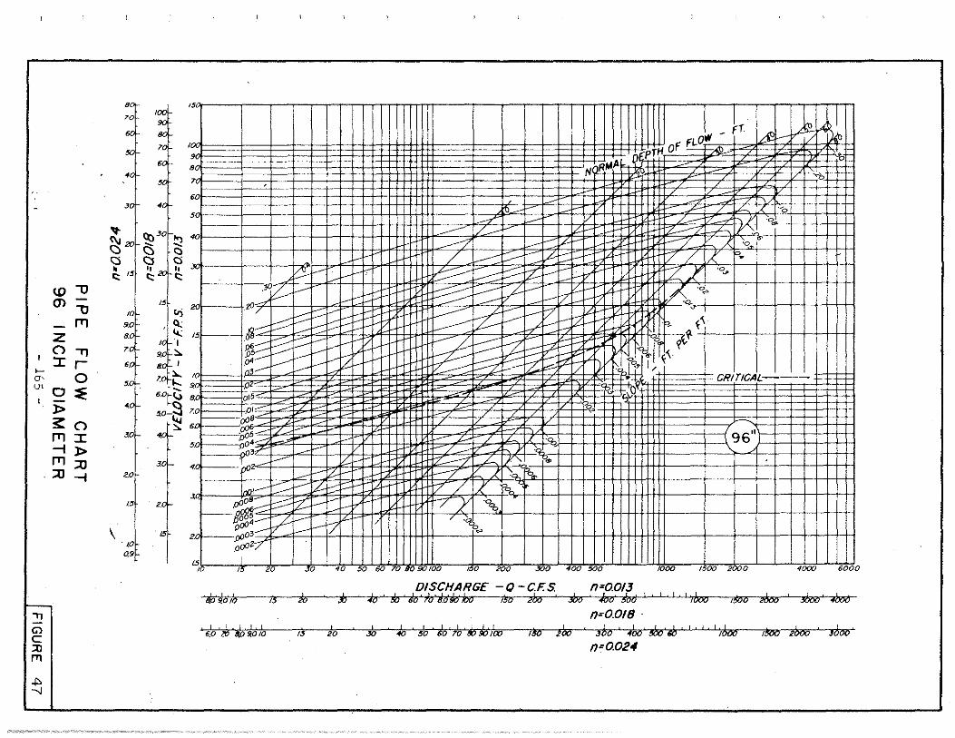
<.D ""O CJ) ""O
ITI z () .,, :r r
;; 0 "' 0 :::E
l>
,, G)
c ::0 fTI
.p. --J
s:: () ITI :r --i l> ITI ::0 ::0 --i
9,
;-oi .,
• ,,
..,. ~ Ci • c::: 15_
\
/Oi ' 9.0
9, ,, ,, ,,
··' •o
2.0
1.51
,o 09
_:i' ..., - -Cl c::. c:i C)
11 h c:; c:;
8 ,, >--
,._ 60' ,_, 5,
-+~-·-+--
t
11nRIAA
~ ,___ I/
---- 1--~ /~ [L.V u-
TL-____,--~ ----
I FlQ'll
I - Ff ~
o{pTH oF
:r }lf / /
/ / I/ ___.
I-+-~
~ -)'f.:++-
v ~:f1ttttt1 p? i.-+ I I I I 1-l
/ h J,
•o"
:~~ tj1i:::t::::t:::tfi:::FlbttrntttJJS~St~f'S~w~~fllf I I I I I I II II
~ J In, ?. .....
-- st<
15:
,0
015~
"•-ti
~t£tl~lllll I I Fl llll Ill CRITICAL·
6.0r(..) B.• -- v
4;
3.0I
-- ,.L / -01::::
·s·~::::: '· pos..c-1./ 5. o4..-- . 3C:
. .J i'° >--4..1 1 .... vf/:--- b-',,. ~ 7 ) \... o.;_
/ / / ,___
v- / I/ ,,~i 1111111111111 I ~62 I 111 tffi / /
- zf: r /
e-.j.- / 7
2.
I !_,,___.~ -------- £-1-;::'.i-e- ~ V -/ J' 0o~ •
, I .o00~----:::::::::::: Z: i---C-:: ~,,.. -~ / y ''lt, -t---~----- L-~ _,,_.. I' , ·~
p(j) i--V- __ v1/ p"'" 2.oJ.--aoo"
ooOi;/ I
"'b k I I I I I I I I I I I l~Lst} I I I I J I I I I • I I I I " I I I I I I I I I I I I I I I I 20 JO 40 50 60 70 8 100 !50 200 0 400 500 1000 1500 2000 4()(XJ 6000
DISCHARGE -O -CF.S. n=0.013 ii ~'oh 13 Si ii JiJ w tio 'lo 80 #o ha !30 2"o :iho i/bo !oo ' ' ' ' ' dw 1!00 m ' :J\oo · ?boiJ
n=0.018 I I 'ia I I S I I I I I ii; ;f;Jb I ~ W , b ' W ~ m I I I ~ ~ liro • ~ 6.0 m 9.010 1 20 30 "° $0 so 1ro , 1 3 o r 1 oo 1 ~ J oo
n=0.024

-Cl) Cl)
LL
c:
c: 0 fJ) fJ)
Cl) .... a. Cl)
0
-0
~ .... 0 ·"' -"' LL
,, G> c ::0 [Tl
"" CP
-0
.s::; -a. Cl)
0
" >-
0.03 0.04
Std. Depression I I II a= 0.208 or 2 Y2
W= 4'-o" 0
n = 0.015
0.05 0.06 0.07 0.08 0.09 0.1 0.15 0.2 0.3 0.4 0.5 0.6 0.7 0.8 0.9 LO 1.5
A= Cross Sectional Area of Flow at Depression in Sq. Ft. Note: When y< WcfTone A=y 2 Tan ~
When y>WcfTon8 A= V2 aw+ 112 (y-a)2 Tan80
Where Tan 8 = ~ ~+a Tan8
0

...... Q)
LO
0.9
0.8
0.7
~ 0.6
c:
c: 0 '(ij
"' Q) .... a. Q)
,o ......... a- 0 _., ,3
0
.,, Gl c ;:o rn
_p, lD
LL
..... 0
..c: ...... a. Q)
Cl II
>.
0.5
0.4
0.3
0.2
0.15
0.
0.09
0.08 0.25 0.3 0.4
Oo= l.o c.f.s.
0.5 06 0.7 0.8 0.9 l.O 1.5 2.0 3.0
Specific Energy of Flow in Feet \l 2
E=Yo+ 20 +a g
4.0 5.0 6.0 7.0 8.0 9.0 10.0 15.0
Std. Depression
a= 0.208'or 2V2" W=4'-o"
0 " Crown Slope= 1:24or1/2 /ft. n=0.015 Tan 90= 24 Ton 9=10.7

-Q) Q)
LL
c::
c:: 0 en en Q) ... 0. Q)
Cl ..... c 3 0 .... -
"''LL 00 ,-
0
.,, G1 c ::0 rT1
Ul 0
.c -0. Q)
Cl II
>-
.0
0.9 Hl±l!!llll I I I I I LltWJE]
0.8
0.7
0.6
0.5
0.4
0.2
015•11111111111111111111
0.1
0.09
0.08 0.25 0.3 0.4 0.5 0.6 0.7 0.8 0.9 1.0 1.5
Oo -~Ocr
. 09~-a.·~s Q~?.cf. .2~-~·S. ~c.f: ~::s~· Q~~s.
Q0~s - a . ·0 Cf •
- .s.
Oo.::2c)'1_" .· C,f.s .
1~:flfr•• _1 --=ij
Oo, l.Q c "Clllllllllllll I I I I I IH+t-1·· -f.s.
'"'i
2.0 3.0 4.0
Specific Energy of Flow in Feet
E =Yo+ Vo2 2g ta
I
•
5.0 6.0 7.0 8.0 9.0 10.0 15.0
Std. Depression
a= 0.208' or 2 Y2" W=4
1-0 11
0 '' Crown Slope=!: 32 or 3/9/ft. n = 0.015 Tan9o=32 Tan9=12

-Q) Q) IL
c: -c: 0 If) If) Q) ..... c. Q)
0 -0 ,_. O' 3: "' 0
.,, Gl c ;;o rn
(JI
IL ._ 0
~ -c. Q)
0 II
>-
Specific Energy
E =Yo+
of Flow in' Feet v. 2
_Q_ ta 2g
Std. Depression l'.
l ' I II o = 0.208 or 2V2 \
W=41-0 11 ~· .
0 • Crown Slope= 1:48 or Y4 !ft. n=0.015 Tan 90=48 Tan e =13.8

1.0
0.9
0.8
0.7 +-(].) (].)
LL c -c 0 VJ VJ (].) .... c. (].)
0 +-
I 0
~ :: co I LL -0
.s::. +-c. (].)
0 II
>.
0.1
0.09
0.08 0.25 0.3 0.4
-, Tl
Gl c ::0 [Tl
(JI I\)
0.5 0.6 0.7 0.8 0.9 1.0 1.5
~·Octs. "-ll 9o~ J;!..o c.fs
Oo,6'~·
o'::'f'o~ Q~~'~· Q~·
3.o c. f.s.··,
0()::: 2.n c_ f.s .
Oo::: I. 0 c· '·"-1!4f+f+Hff-H-++f+-1 . f.s.
2.0 3.0
Specific Energy of Flow in Feet ~ 2
E =Yo+ _g_ +a 2g
4.0 5.0 6.0 7.0 8.0 9.0 10.0 15.0
Std. Depression
a= 0.208'or 2 1'2" W=4
1-0
11
0 tt
Crown Slope= 1:64 or 3/16/ft. n= 0.015 Tan eo= 64 Tan 9=14.7

-Q) Q)
LL
c:
c: 0 U) U) Q) ... a. Q)
0 -a
~ .... 0 ....,_ ,_.LL
,, Gl c ::0 fTI
(Jl (J.J
-0
..c: -a. Q)
0 II
>,
0.3 0.4 0.5 Q6 0.7 0.8 0.9 1.0 1.5
Oo~iooc.f.5 Oo~ao ~"·'-s. Oo~s~~ Q~uc.f.s ~~
•o.c,~·
c . s Q" .
De.rs .... ,
.. Of\:: :!.o c.f.s.
i;j~ .. ·f'l- f.Oc.fs.
2.0 3.0
Specific Energy of Flow in Feet \l 2
E =Yo+ _Q_ +a 2g
4.0 5.0 6.0 7.0 8.0 9.0 10.0 15.0
Std. Depression I I II a =0.208 or 2Yz
W=41-0 11
0
Crown Slope= 1: 96 or Vs'Yft. n = 0.015 Tan 60=96 Tan e =16

1.0
0.8
0.6
q -q2
0.4
0.2
0
~ ~~ ~ l~ \~\ ~ ~ ~ ~ ~ ~ ~~ ~1'
\ ~ N -~ ,, 0 ~q, ''\. . 9
~ ~ ~ ~ "" ~ ~ ~ ~ ~ !"'-. "-..
~ ~ ~ ~'
0 0.4 0.8 1.2 1.6
2~
( vg ~:n e) 5
SOLUTION FOR CARRY-OVER FLOW q
FOR INLETS ON GRADE (DEPRESSED)
From Figure 22 1 Page 107, uThe Design of Storm Water Inlets'; John Hopkins University, 1956
- 172 -
'
~ ~ :--...
2.0 2.4
I FIGURE 54