fmv product manual - frigokimo.com · this product manual includes the following important...
TRANSCRIPT

PMM-FMV.2-1508 1117.122-002_02
Product Manual
MotorMaster
Fully digital
Frequency Inverter
with integrated Vector
control
MM 0.37...1.5FMV/S230-EMC
MM 0.75...7.5FMCV-emc Software Version 4.x
This Product Manual includes the following important information in connection with the CE marking: - Validity - Planning the installation, mounting
and wiring, commissioning, servicing
P
rod
uct
Man
ua
l
Mo
torM
aste
r F
MV
P
MM
FM
V.2
-15
08

WARNINGS, RISKS AND IMPORTANT INFORMATION
0-2 KIMO MotorMaster FMV Frequency Inverter
Software version
This Product Manual is compatible with MM FMV Frequency Inverters with software version
4.X. Please contact your supplier should MM FMV Frequency Inverter indicate a different
software version on power-up.
Installation details
Serial number:
(see product label or name plate)
Where installed:
(for your own information)
MM FMV Frequency Inverter as in Component Relevant Apparatus
EMC DIRECTIVE used as:
Mounting: Enclosure
Copyright KIMO 2015
All rights strictly reserved. No part of this document may be stored in a retrieval system, or transmitted in any form or by any means without written permission from the copyright holder. None observance of this copyright will result in liability for damages.
Although every effort has been taken to ensure the accuracy of this document it may be necessary, without notice, to make amendments or correct omissions, the manufacturer cannot accept responsibility for damage, injury, or expenses resulting therefrom.
KIMO RHVAC Controls Ltd Hüttendorfer Weg 60, D-90768 Fürth Tel. +49 911-8018778 Fax +49 911-9976118 E-Mail: [email protected] http://www.frigokimo.com
Issue 4.X/02
24.08.15

WARNINGS, RISKS AND IMPORTANT INFORMATION
MotorMaster FMV Frequency Inverter KIMO 0-3
Available product documentation MM FMV Frequency Inverters use a revolutionary software concept which provides for: • Easy use and programming for normal applications • High level of flexibility and sophistication for complex volume applications To cater for the needs of these two user groups the product documentation is structured as follows: Documentation Contents Chapters Status
Product Manual PMM-FMV.2-0605
• Technical data, installation, CE, EMC, LVD and UL issues, options
• Setting-up and commissioning for all normal applications
0...12 Supplied with every MM FMV Frequency Inverter

CONTENTS ...................................................................................................................... PAGE
0-4 KIMO MotorMaster FMV Frequency Inverter
WARNINGS, RISKS AND impoRtant information Software Version .........................................................................................0-2 WARNINGS, RISKS ..................................................................................0-9
Read before proceeding
SPECIAL INSTRUCTIONS ......................................................................0-11 SCOPE OF THIS PRODUCT MANUAL..................................................0-12 TECHNICAL CHANGES..........................................................................0-12 WARRANTY .............................................................................................0-12 Chapter 1 - PRODUCT OVERVIEW GENERAL DESCRIPTION .....................................................................................................1-2 TECHNICAL OVERVIEW......................................................................................................1-3
Component Overview...................................................................................1-3 TECHNICAL DATA ................................................................................................................1-4
General .........................................................................................................1-4 Environmental requirements.........................................................................1-4 Safety............................................................................................................1-5 EC-Directives ...............................................................................................1-5 Power circuit 230 V types ............................................................................1-6 Power circuit 400 V types ............................................................................1-7 Voltage supply..............................................................................................1-8 Control circuit...............................................................................................1-8 Special considerations for installation in compliance with UL ....................1-9
ORDERING INFORMATION ...............................................................................................1-10 Ordering information for 230 V types ........................................................1-10 Ordering information for 400 V types ........................................................1-10 Ordering information for Accessories ........................................................1-10
CHAPTER 2 - PRE-INSTALLATION PLANNING FUNCTIONAL OVERVIEW...................................................................................................2-2 BASIC WIRING AND BLOCK DIAGRAMS.........................................................................2-4
Fig. 2.1: General wiring diagram of power sections.....................................2-4 Fig. 2.2: General wiring diagram of control circuit ......................................2-5 Fig. 2.3: Control wiring for MACROs .........................................................2-5
TERMINAL DESCRIPTIONS.................................................................................................2-6 Power terminals ............................................................................................2-6 Control terminals ..........................................................................................2-7 Serial Interface P3 ........................................................................................2-8 Encoder Connection .....................................................................................2-8

CONTENTS ...................................................................................................................... PAGE
MotorMaster FMV Frequency Inverter KIMO 0-5
Chapter 3 - MOUNTING AND INSTALLATION PRECAUTIONS .......................................................................................................................3-2 EQUIPMENT INSPECTION....................................................................................................3-2 MOUNTING .............................................................................................................................3-2 INSTALLATION......................................................................................................................3-4
Using screwless cage-clamp terminals .........................................................3-4 Power wiring.................................................................................................3-6 Overload and short-circuit protection ...........................................................3-6 Earthing ........................................................................................................3-7 Control wiring...............................................................................................3-8
EMC INSTALLATION INSTRUCTIONS ..............................................................................3-9 Introduction ..................................................................................................3-9 EMC filters to reduce line-conducted noise..................................................3-9 Interaction and safety considerations with earth-fault monitoring systems 3-11 Minimising radiated emission.....................................................................3-11 Screening and earthing when mounted in an enclosure..............................3-13 Motor cable-length limitations....................................................................3-15 Other layout considerations ........................................................................3-16
Chapter 4 - SETTING-UP AND COMMISSIONING PROGRAMMING PAD ...........................................................................................................4-2
Introduction ..................................................................................................4-2 LCD Display.................................................................................................4-3 Drive Status Indications................................................................................4-3 Function keys for operating and programming the MM FMV .....................4-4 Selecting (LOcAL / REMOTE mode) ..........................................................4-5
IMPORTANT OPERATIONS WITH THE PROGRAMMING PAD ....................................4-6 Resetting to Factory Defaults .......................................................................4-6 Password protection......................................................................................4-6 Quick Application selection (MACRO selection) ........................................4-7
SETTING-UP AND ENERGIZING THE DRIVE ...................................................................4-8 First-time check of electrical system ............................................................4-8 Safety considerations ....................................................................................4-8 Setting up the drive before energizing..........................................................4-9 Energizing the drive....................................................................................4-10

CONTENTS ...................................................................................................................... PAGE
0-6 KIMO MotorMaster FMV Frequency Inverter
Chapter 5 - PROGRAMMING THE APPLICATION GENERAL ................................................................................................................................5-2
Programming ................................................................................................5-2 Menu structure..............................................................................................5-3
MENU PARAMETER..............................................................................................................5-4 Application macros.......................................................................................5-4 Maximum and minimum speed ....................................................................5-5 Ramps ...........................................................................................................5-5 Motor current................................................................................................5-5 Base frequency .............................................................................................5-5 Jog setpoint ...................................................................................................5-6 Run Stop selection ........................................................................................5-6 V/F shape......................................................................................................5-6 Current Limit ................................................................................................5-7 Fixed boost ...................................................................................................5-7 Password.......................................................................................................5-7 Speed preset..................................................................................................5-8 Ramp function with preset speed..................................................................5-8 PID controller ...............................................................................................5-9
MENU DIAGNOSTICS .........................................................................................................5-12 MENU CTRL..........................................................................................................................5-12 MENU SETUP........................................................................................................................5-17
Input Menu - Digital Inputs...................................................................5-17 - Analog Inputs .................................................................5-18 Output-Menu - Analog Output .................................................................5-19 - Digital Outputs ................................................................5-20 - Relay Output....................................................................5-21 Trip Menu...................................................................................................5-21 SERL Menu ................................................................................................5-22 Diverse Setup Menu ...................................................................................5-24 Auto restart .................................................................................................5-25 Skip frequencies .........................................................................................5-27
MENU ENCODER .................................................................................................................5-28 Chapter 6 - TRIPS, DIAGNOSTICS AND FAULT FINDING INTRODUCTION.....................................................................................................................6-2
Trip warning message...................................................................................6-2 When a trip occurs........................................................................................6-2 Resetting a trip..............................................................................................6-2 Using the Operator Station to manage trips..................................................6-2
TRIPS........................................................................................................................................6-3 MAIN MENU - DIAGNOSTICS .............................................................................................6-7 OTHER FAULT FINDING ......................................................................................................6-8

CONTENTS ...................................................................................................................... PAGE
MotorMaster FMV Frequency Inverter KIMO 0-7
Chapter 7 - SERVICING MAINTENANCE......................................................................................................................7-2 REPAIR.....................................................................................................................................7-2 SAVING APPLICATION DATA BEFORE RETURNING EQUIPMENT ............................7-2 RETURNED EQUIPMENT......................................................................................................7-3 DISPOSAL................................................................................................................................7-3 Kapitel 8 - EEC DIRECTIVES, THE CE MARKING, UL, CSA BASICS OF 'CE' MARKING ...................................................................................................8-2 EMC DIRECTIVE ....................................................................................................................8-3
Responsibility for EMC and 'CE' marking....................................................8-3 Consideration of EMC environment.............................................................8-6 'CE' marking with external EMC filter .........................................................8-8 Specification of achievable EMC emission and immunity ...........................8-9 EMC responsibility of installers and users of MM FMV Frequency Inverters in installations .................................................................................................8-10 EMC responsibility of manufacturers of apparatus and machines sold as complete functional units............................................................................8-10 EC Declaration of Conformity for EMC ....................................................8-11 Manufacturer's EMC declaration ................................................................8-12
LOW VOLTAGE DIRECTIVE..............................................................................................8-13 MACHINERY DIRECTIVE...................................................................................................8-14 UL FOR USA AND CANADA ..............................................................................................8-15 Chapter 9 - POWER INDEPENDENT OPTIONS
RS232/485 interface .....................................................................................9-2 Chapter 10 - POWER RELATED OPTIONS
Summary of available options ....................................................................10-2 EMC filters for 3AC 400 V types...............................................................10-3 Line and motor chokes................................................................................10-4 Motor filters for 3AC 400V types...............................................................10-5 External braking resistors ...........................................................................10-6
CONTENTS ...................................................................................................................... PAGE
0-8 KIMO MotorMaster FMV Frequency Inverter
Chapter 11 - APPLICATION NOTES
General .......................................................................................................11-2 EMC considerations ...................................................................................11-2 Minimum connection requirements ............................................................11-2 Brake motors...............................................................................................11-4 Synchronous motors with reluctance or permanent magnet rotors.............11-4 Slip-ring induction motors..........................................................................11-5 High-speed motors......................................................................................11-5 Pole-change motors ....................................................................................11-5 Using line chokes........................................................................................11-5 Using motor chokes ....................................................................................11-6 Using multiple motors on a single MM FMV Frequency Inverter .............11-6 Switching at the inverter output..................................................................11-7 High starting torque ....................................................................................11-7
Chapter 12 - APPLICATION MACROS GENERAL ABOUT APPLICATION MACROS ..................................................................12-2 MACRO 1 - Basic speed control ...........................................................................................12-3 MACRO 2 - Auto / Manual Control.....................................................................................12-4 MACRO 3 - Preset speeds .....................................................................................................12-5 MACRO 4 - Raise / Lower ....................................................................................................12-6 MACRO 5 - PID controller ...................................................................................................12-7

WARNINGS, RISKS AND IMPORTANT INFORMATION
MotorMaster FMV Frequency Inverter KIMO 0-9
WARNINGS, RISKS The following warnings and risks are included to enable the user to obtain the maximum effectiveness and to alert the user to safety issues.
WARNING
Installation, operation, programming and maintenance of the equipment should be carried out by qualified personnel. A qualified person is someone who is technically competent and familiar with all safety information and established safety practices; with the installation process, operation and maintenance of this equipment; and with all the hazards involved. Non-compliance with this warning may result in lethal personal injury and/or equipment damage. Never work on any control equipment without first isolating all power supplies from the equipment. The capacitors in the d.c. link carry high voltages also after switching off. Wait at least 3 min before removing the protective cover, otherwise there is a high risk of electric shock. Measure the DC+ and DC- terminal voltage to confirm that the voltage is less than 50 V. The drive motor must be connected to an appropriate safety earth. Failure to do so presents an electrical shock hazard. The heat sink can reach a temperature of up to 90 °C.
CAUTION
These MM FMV inverters were tested before they left our factory. However, before installation and start-up, inspect all equipment for transit damage, loose parts, packing materials etc. Never perform high voltage resistance checks on the wiring without first disconnecting the MM FMV Frequency Inverter from the circuit being tested.
ELECTROSTATIC SENSITIVE COMPONENTS
This equipment contains electrostatic discharge (ESD) sensitive components. Observe static control precautions when handling, installing and servicing this product.
REPLACING EQUIPMENT
When replacing a MM FMV Frequency Inverter it is essential that all user defined parameters that determine drive operation are correctly installed before putting back into service. Failure to do so may create a hazard or risk of lethal injury.

WARNINGS, RISKS AND IMPORTANT INFORMATION
0-10 KIMO MotorMaster FMV Frequency Inverter
INSTALLATION
This product conforms to IP20 protection. Due consideration should be given to the appropriate regulations of safety and protection in accordance with the environmental conditions of installation. To maintain compliance with the European LOW-VOLTAGE DIRECTIVE as in EN50178, the MM FMV Frequency Inverter should preferably be mounted in a suitable enclosure requiring a tool for opening. Ensure that - mechanically secure fixings are used as recommended - cooling and air flow around the product are as recommended. - cables and wire terminations are as recommended and clamped to required torque. - the installation and commissioning of this product are carried out by a qualified competent person. - the product rating is not exceeded. This equipment must be permanently earthed due to the relatively high leakage current.
APPLICATION RISK
The integration of this product into other system is not the responsibility of the supplier or manufacturer as to its applicability, effectiveness or safety of operation or of other apparatus or systems. Where appropriate the user should consider the relevant aspects of the following risk assessment.
RISK ASSESSMENT
Under fault conditions or conditions not intended: - The motor speed may be incorrect. - The motor speed may be excessive. - The direction of rotation may be incorrect. - The motor may be energized (unless suitable precautions are taken in the installation). In all situations the user should provide sufficient guarding to prevent risk of injury and/or install suitable monitoring and safety systems in accordance with safety regulations.

WARNINGS, RISKS AND IMPORTANT INFORMATION
MotorMaster FMV Frequency Inverter KIMO 0-11
SPECIAL INSTRUCTIONS APPLICATION AREA:
Speed control of three-phase induction or synchronous motors in industrial applications (non consumer)
APPLICATIONS ADVICE:
Applications advice and training is available from your supplier.
POWER LOSS: During power loss the MM FMV inverter will not operate as specified.
The power should not be reapplied for a period of 30 s to allow the inverter limit circuit to operate correctly.
MAINTENANCE: Maintenance should only be performed by trained competent persons
in accordance with the manufacturer's instructions using only the recommended spares (or return to supplier for repair). Use of unapproved spare parts may create a hazard and risk of injury. Refer to MAINTENANCE, page 7-2 for more details.
REPAIRS The supplier should be contacted if a MM FMV Frequency Inverter is
defect. A repair can be arranged at the manufacturers , authorized agent. Repair reports can only be given if a sufficient and accurate defect report is returned with the defect inverter.
PACKAGING: The packaging is combustible and if disposed of in this manner
incorrectly may lead to the generation of toxic fumes which are lethal. WEIGHT: Consideration should be given to the weight of the product when
handling. PROTECTIVE INSULATION:
All exposed metal parts are protected by basic insulation and bonding to earth i.e. Class I. Earth bonding is the responsibility of the installer. All signal terminals are protected by double insulation, i.e. Class II insulation. The purpose of this protection is to allow safe connection to other low voltage equipment.
RISK OF ELECTRIC SHOCK OR INJURY:
MM FMV Frequency Inverter used without the required precautions can represent an electrical hazard and risk of severe personal injury. Rotating or moving parts or structures powered by the inverter also represent a mechanical hazard with risk of severe personal injury or damage to machinery or property.

WARNINGS, RISKS AND IMPORTANT INFORMATION
0-12 KIMO MotorMaster FMV Frequency Inverter
SCOPE OF THIS PRODUCT MANUAL This Product Manual describes the operation of MM FMV Frequency Inverters. It is not intended that this Product Manual describes the function of the apparatus or system into which the MM FMV Frequency Inverter is installed. This Product Manual is to be made available to all persons who are required to design an installation using the MM FMV Frequency Inverter or to install, set up, commissioning, service operate or are in any way involved with the MM FMV Frequency Inverter itself. These persons who must be suitably qualified must read this Product Manual thoroughly and completely before beginning with the installation and commissioning.
TECHNICAL CHANGES The manufacturer reserves the right to change the content and product specification without notice.
WARRANTY This piece of equipment is warranted against defects in design materials and workmanship for a period of 12 month from the date of delivery as detailed in the general terms of supply and payment of the ZVEI (Federation of the German Electrical Industry).

Chapter 1 - PRODUCT OVERVIEW
MotorMaster FMV Frequency Inverter KIMO 1-1
Chapter 1 - PRODUCT OVERVIEW Page GENERAL DESCRIPTION .....................................................................................................1-2 TECHNICAL OVERVIEW......................................................................................................1-3
Component Overview...................................................................................1-3 TECHNICAL DATA ................................................................................................................1-4
General..........................................................................................................1-4 Environmental requirements.........................................................................1-4 Safety ............................................................................................................1-5 EC-Directives ...............................................................................................1-5 Power circuit 230 V types.............................................................................1-6 Power circuit 400 V types.............................................................................1-7 Voltage supply ..............................................................................................1-8 Control circuit ...............................................................................................1-8 Special considerations for installation in compliance with UL ....................1-9
ORDERING INFORMATION ...............................................................................................1-10 Ordering information for 230 V types ........................................................1-10 Ordering information for 400 V types ........................................................1-10 Ordering information for Accessories ........................................................1-10

Chapter 1 - PRODUCT OVERVIEW
1-2 KIMO MotorMaster FMV Frequency Inverter
GENERAL DESCRIPTION MM FMV Frequency Inverters:
♦ Suitable for the speed control of standard 3-phase induction motors (squirrel-cage motors with fixed or variable speed)
♦ Universally suitable for general industry applications with a constant torque requirement as well as for fans and pumps with a quadratic load characteristic
♦ Can be supplied for the following supply voltages: for motors up to
1AC: 220...240 V ±10 % 1.5 kW 3AC: 380...460 V ±10 % 7.5 kW
♦ Universally suitable for nearly all drive applications ♦ Optimum cost/performance
Powerful microprocessor control and software:
♦ Simple programming and diagnostics with an operating panel consisting of 4 character LCD display and 6 keys to allow basic operation control in LOCAL MODE.
♦ Sine-wave PWM modulation in the full speed range ♦ Special low-noise quiet-pattern PWM ♦ Advanced protection functions
EMC: ♦ All 1AC MM FMV Frequency Inverters are supplied with a built-in EMC filter to class B interference protection. All 3AC MM FMV Frequency Inverters are supplied with a built-in EMC filter to class A interference protection. Please refer to supplier for difficult applications (e.g. long cable runs).
MM FMV Options:
♦ RS232 serial link ♦ Braking resistors ♦ KimoVis software for operating and programming (WINDOWS)
Parts supplied: ♦ MM FMV Frequency Inverter incl. Programming Pad ♦ Product Manual PMM-FMV.2 including parameter list
Further documentation:
♦ EMC Compendium AF-MM-02 ♦ Product information CE marking of electronic drive equipment PI-LKTM-005

Chapter 1 - PRODUCT OVERVIEW
MotorMaster FMV Frequency Inverter KIMO 1-3
TECHNICAL OVERVIEW Component Overview
5 6 7
4
1
8
3
2
10
11
12
Fig. 1.1: Frequency Inverter MM 3.0...7.5FMCV-emc
MM 1.5FMV/S230-emc MM0.75...2.2FMCV-emc MM0.37...0.75FMV/S230-EMC
1 Frequency Inverter – housing 2 Programming pad 3 DIN clip /fixing bracket 4 Terminal cover 5 Power terminals 6 Clamp for screened motor
cable 7 Control terminals 8 Volt free relay contacts 9 Product rating label 10 Motor thermistor terminals 11 RS232 Interface P3 12 Digital inputs / encoder
connection
Baugröße 2 B augröße 1 B augröße 3
9
MM0.37...0.75FMV/ S230-EMC MM 1.5FMV/S230-emc, MM0.75...2.2FMCV-emc MM 3.0...7.5FMCV-emc

Chapter 1 - PRODUCT OVERVIEW
1-4 KIMO MotorMaster FMV Frequency Inverter
TECHNICAL DATA General Control; Full local control via the operating panel or with external analog and
digital control inputs Output frequency: 0...240 Hz Switching frequency: 4 kHz Stopping modes: Ramp, Ramp with d.c. holding pulse, d.c. injection braking , coast,
FRAMP (fast ramp) Ramps: Ramp up, ramp down, fast stop and S-Ramps PID-Controller: Universally programmable PID controller Link: Serial link RS232/485 (Option), RS232 integrated Hoisting and travel drives:
Integrated ramp functions and brake control
Password: Integrated password protection for customer-set parameters Jog: Adjustable jog speed
Programming pad:
Removable, 4 character LCD display (illuminated), 6 function keys
Protection; Trip conditions:
Short circuit line - line, heat sink overtemperature, overvoltage, undervoltage, input for external trips (e.g. for connection of an external thermistor relay)
Current limit: 0...150 % rated current for 30s V/f characteristic: Linear: for constant torque
Quadratic: pumps and fans Adjustments: base frequency and voltage
Diagnostics: Trips are displayed
Inputs/outputs; Analog inputs: 2 Analog output: 1 Digital inputs: 6 Digital outputs: 1 x Relay Digital I/O: 1 Thermistor input: 1
Environmental requirements Permissible temperature:
0 ...+45 °C Operation 2 %/°C derating, e.g. 80 % with 50 °C
-25 ...+55 °C Storage -25 ...+70 °C Transport (short term)

Chapter 1 - PRODUCT OVERVIEW
MotorMaster FMV Frequency Inverter KIMO 1-5
Climatic condition: Class 3K3 (EN60721-3-3) 5...85 % relative humidity Other requirements: Dust free (see pollution) non-
corrosive and non-flammable Pollution; Degree 2 pollution
(IEC 664-1): Dry non-conducting dust or particles, infrequent light condensation when switched off permissible
Altitude: ≥1000 m above sea level 1 % / 100 m power derating Safety Relevant standards: Europe:
North America, Canada:
EN50178 (1998) valid for - Enclosure mounting UL508C valid for: - Enclosure mounting as"Open-type Drive"
Overvoltage category (IEC664-1 (1992)):
III
Only for use with TT/TN voltage supplies with an earthed neutral
Rated insulation voltage to PE:
AC 460 V
Protective class: (IEC 536 (1976))
I Basic insulation with PE connection (protective earth). The user is responsible for the PE connection
IP Protection: (EN 60529 (1991))
Enclosure mounted:
All surfaces IP20
UL (c-UL): Enclosure rating
Enclosure mounted:
Open type
Prospective short circuit current:
≤ 5 kA ≤10 kA
(220...240 V) (380...460 V)
Earthing: Permanent earthing is mandatory. The following method can be used: - Use two independent earth conductors each connected parallel to a
separate earth terminal of the MM FMV Frequency Inverter. NOTE: Each conductor itself must meet the local requirements
for protective earth conductors.
EC-Directives EMC-DIRECTIVE: The requirements of the European EMC-DIRECTIVE are met with
approved external EMC filters. The EMC Installation Instructions (page 3-9...18) and information on applying the EMC DIRECTIVE (page 8-3...12) must be observed.
LOW VOLTAGE DIRECTIVE:
The requirements of the European LOW VOLTAGE DIRECTIVE for CE marking are adhered to, refer to pages 8-13.

Chapter 1 - PRODUCT OVERVIEW
1-6 KIMO MotorMaster FMV Frequency Inverter
Power circuit 230 V types Product code
MotorMaster 0.37FMV/
S230 -EMC
0.75FMV/ S230 -EMC
1.5FMV/ S230 -EMC
Supply voltage: 1AC 220...240 V, ±10 %, 50... 60 Hz, ±10 Hz
Normal operation with 50 % overload / 30 sec Rated motor power kW 0,37 0,75 1,5 Motor current A 2,2 4 7 Motor cable Europe 5) mm2 1 1 1 Motor cable North America 6) AWG 12 12 12 Switching frequency kHz 4 4 4 Max. losses 4 kHz W 32 52 82 Supply current A 6,2 10,5 16,0 Supply fuse/Circuit breaker 1) A 10 16 20 Supply cable Europe 5) mm2 1/1,5 1,5/2,5 2,5/4 Supply cable North America 6) AWG 12 12 12 Earth leakage current mA >10 >10 >10 Fuse for UL compliance2) A 10 15 20
Integrated braking chopper: Data braking chopper: - ED % - - - - Duty cycle s - - - - Max. current (peak) A - - - - Continuous current A - - - - Minimum value Ω - - - Ext. braking resistor - Type - - -
Installation, Mounting: Cooling Fan Fan Fan Weight approx.: - MotorMaster Frequency Inverter kg 0,85 0,85 1,4 - Programming Pad (Option) kg 0,06 0,06 0,06 Dimensions: - Height mm 145 145 205 - Height with top cover mm - - Width mm 73 73 73 - Depth mm 142 142 172 Air flow clearance: - Above / below mm 100 100 100 - Left / right mm 0 0 0 - Front with wall mounting mm 15 15 15 Power terminals: - Max. conductor size mm2 2,5 2,5 2,5 - Max. torque Nm Terminals for braking - Max. conductor size mm2 - - - chopper: - Max. torque Nm - - - Thermistor/ - Max. conductor size mm2 2,5 2,5 2,5 Control terminals - Min. conductor size mm2 0,08 0,08 0,08 Outline drawing: Refer to page 3-3 3.1a 3.1a 3.1b
1) Fuse or circuit breaker with delayed release 2) UL Listed JDDZ, class K5 or H;
UL Listed JDRX, class H
3) For operation to UL Size of cables in accordance with: 5) EN60204-1 / E DIN VDE 0298-4 (see page 3-7) 6) NEC/NEPA-70

Chapter 1 - PRODUCT OVERVIEW
MotorMaster FMV Frequency Inverter KIMO 1-7
Power circuit 400 V types 0.75FMCV
-emc 1.5FMCV-emc
2.2FMCV-emc
3.0FMCV/-emc
4.0FMCV/-emc
5.5FMCV/ -emc
7.5FMCV/ -emc
3A C380...460 V, ±10 %, 50... 60 Hz, ±110 Hz
Operation with 50 % overload / 30 s kW 0,75 1,5 2,2 3,0 4,0 5,5 7,5 kW A 2,5 4,5 5,5 6,8 9 12 16 A mm2 1 1 1 1 1/1,5 1,5 2,5 mm2 AWG 12 12 12 10 10 10 10 AWGkHz 4 4 4 4 4 4 4 kHz W 40 61 70 80 100 136 180 W A 4,1 7,5 9,4 11,1 13,9 18 23,6 A A 10 10 10 16 16 20 25 A mm2 1/1,5 1/1,5 1/1,5 1,5/2,5 1,5/2,5 2,5/4 4/6 mm2 AWG 12 12 12 10 10 10 10 AWGmA >10 >10 >10 >10 >10 >10 >10 mA A 10 10 15 15 20 25 30 A
Integrated braking chopper: % 100 100 100 30 30 30 30 % s 120 120 120 120 120 120 120 s A 1,5 3,75 3,75 7,5 7,5 13,5 13,5 A A 1,5 3,75 3,75 2,3 2,3 4,0 4,0 A Ω 500 200 200 100 100 56 56 Ω A0.08RE500 A0.43RE220 A0.43RE220 A1.2RE100 A1.2RE100 A1.2RE56 A1.2RE56
Installation, Mounting: Fan Fan Fan Fan Fan Fan Fan kg 1,4 1,4 1,4 2,7 2,7 2,7 2,7 kg kg 0,06 0,06 0,06 0,06 0,06 0,06 0,06 kg mm 205 205 205 262 262 262 262 mm mm - - - - - - - mm mm 73 73 73 96 96 96 96 mm mm 172 172 172 202 202 202 202 mm mm 100 100 100 100 100 100 100 mm mm 0 0 0 0 0 0 0 mm mm 15 15 15 15 15 15 15 mm2 mm2 2,5 2,5 2,5 6 6 6 6 mm Nm Nm mm2 2,5 2,5 2,5 6 6 6 6 mm2 Nm Nm mm2 2,5 2,5 2,5 2,5 2,5 2,5 2,5 mm2 mm2 0,08 0,08 0,08 0,08 0,08 0,08 0,08 mm2 3.1b 3.1b 3.1b 3.1c 3.1c 3.1c 3.1c

Chapter 1 - PRODUCT OVERVIEW
1-8 KIMO MotorMaster FMV Frequency Inverter
Voltage supply Frequency Inverters MM.FMV are only for TT/TN supplies with an earthed neutral, for use with IT-supplies please refer to manufacturer. Control circuit
Reference and
Reference supply for analog inputs +10 V ± 5 %, 10 mA max. load
auxiliary supplies
Auxiliary supply for digital inputs +24 V ±15 %, 50 mA max. load
Analogue I/O Inputs Outputs
Range 0...5 V/0...+10V 0/4...20 mA 0...+10 V
Impedance 20 kΩ 230 Ω 20 kΩ
Limit value +24 V 6 V max. 10 mA*
Resolution 10 bit (1 in 1024) 10 bit (1 in 1024)
Sample rate 5 ms 5 ms * Short-circuit protection
Digital I/O Inputs Outputs (Relay) Outputs
Logic system DC 24 V Industry logic
Isolated relay contacts
Switching '0' <+5 V open open (up to +30 V)
levels '1' >+15 V closed controlled (approx. +1V)
Absolute max. voltage range
-30...+30 V 250 V AC 24 V DC
23 V (min. 19 V)
Impedance 3,2 kΩ 33 Ω
Max. current 7,5 mA 6 A - res. load 50 mA
Sample rate 5 ms 5 ms
Thermistor motor protection
An input for connecting to an external motor thermistor device is available with the MM FMV Frequency Inverter. Conductors of up to 2.5 mm2 (12 AWG) may be connected. The use of 1...2.5 mm2 as in EN 60204-1 is recommended.
Control terminals
Cage-clamp terminals without screws for 0.08...2.5 mm2 conductors (ferrules not required). The use of 0.2...0.75 mm2 as in EN 60204-1 is recommended.

Chapter 1 - PRODUCT OVERVIEW
MotorMaster FMV Frequency Inverter KIMO 1-9
Special considerations for installation in compliance with UL
Solid state motor overload protection:
♦ These MM FMV Frequency Inverters provide Class 10 motor overload protection. The maximum internal overload protection level (current limit) is 150 % for 30 s. Refer to Chapter 4 - SETTING UP AND COMMISSIONING.
An external motor overload protective device must be provided by the installer where the motor has a full load ampere rating of less than 50 % of the Inverter output rating.
Short circuit rating of supply:
♦ All MM FMV Frequency Inverters are suitable for use on a circuit capable of delivering not more than 10,000 A rms symmetrical, 240 V / 460 V.
Solid state short-circuit protection:
♦ These MM FMV Frequency Inverters are provided with Solid-State Short-Circuit (output) Protection. Branch circuit fusing requirements must be in accordance with the latest edition of the National Electric Code NEC/NFPA 70.
Recommended branch circuit protection:
♦ It is recommended that UL Listed (JDDZ) non-renewable cartridge fuses, Class K5 or H; or UL Listed (JDRX) renewable cartridge, Class H, are installed upstream of the Inverter. Refer to page 1-8/9 for recommended fuse ratings.
Motor base frequency: ♦ The maximum settable base frequency is 240 Hz. Field wiring temperature rating:
♦ Use copper conductors only: min. 60/75 °C ambient temperature
Field wiring terminal markings:
♦ For correct field wiring connections that are to be made to each terminal refer to Power terminals, page 2-8/9, and Control terminals, page 2-9...12.
Power wiring terminals: ♦ Refer to the table on page 1-8…13 for maximum conductor sizes. Terminal tightening torque:
♦ Refer to the table on page 1-8…13 for maximum tightening torques.
Field grounding terminals:
♦ The field grounding terminals are identified with the International Grounding Symbol (IEC Publication 417, Symbol 5019). Refer to page 2-4/8 and 3-5/6 for further information.
Operating ambient temperature:
♦ The maximum operating ambient temperature rating is 45 °.

Chapter 1 - PRODUCT OVERVIEW
1-10 KIMO MotorMaster FMV Frequency Inverter
ORDERING INFORMATION Ordering information for 230 V types Function Product code Technical data Order no.
MM 0.37FMV/S230-EMC 0.37 kW, 1AC 220-240 V, 2,2 A 08679.204-110/01.4X
MM 0.75FMV/S230-EMC 0.75 kW, 1AC 220-240 V, 4,0 A 08679.206-110/01.4X
Digital Frequency Inverter with integrated EMC filter for operation with 1AC 220...240 V MM 1.5FMV/S230-EMC 1.5 kW, 1AC 220-240 V, 7,0 A 08679.211-110/01.4X
Ordering information for 400 V types Function Product code Technical data Order no.
MM 0.75FMCV-emc 0.75 kW, 3AC 380-460 V, 2,5 A 08679.306-110/01.4X
MM 1.5FMCV-emc 1.5 kW, 3AC 380-460 V, 4,5 A 08679.311-110/01.4X
Digital Frequency Inverter with integrated EMC filter for operation with 3AC 380...460 V MM 2.2FMCV-emc 2.2 kW, 3AC 380-460 V, 5,5 A 08679.312-110/01.4X
MM 3.0FMCV-emc 3.0 kW, 3AC 380-460 V, 6,8 A 08679.313-110/01.4X
MM 4.0FMCV-emc 4,0 kW, 3AC 380-460 V, 9,0 A 08679.314-110/01.4X
MM 5.5FMCV-emc 5,5 kW, 3AC 380-460 V, 12 A 08679.315-110/01.4X
MM 7.5FMCV-emc 7,5 kW, 3AC 380-460 V, 16 A 08679.316-110/01.4X
Ordering information for Accessories Function Product code Technical data Order no. Removable Programming Pad
MM O-FM-PROG-TTL Programming pad 08620.003
Programming pad for remote mounting
MM O-FM-PROG-RS232 Programming pad with RS232 Interface
08620.004
RS232/485 interface for programming the MM FMV Frequency Inverter
MM O-FM-RS232/485 RS232/485 Interface 08620.005
Clone Module MM O-FM-CLONE Clone module 08620.006 Connection Cable MM A-PROG-CC-3m Connection cable 3 m 08629.004 RS232 Connection cable for PC
MM O-FM-CON-RS232 Connection cable 08620.007/00
Blind Cover MM O-FM-COVER Blind Cover 08620.008

Chapter 2 -PRE-INSTALLATION PLANNING
MotorMaster FMV Frequency Inverter KIMO 2-1
Chapter 2 - PRE-INSTALLATION PLANNING Page FUNCTIONAL OVERVIEW ...................................................................................................2-2 BASIC WIRING AND BLOCK DIAGRAMS.........................................................................2-4
Fig. 2.1: General wiring diagram of power sections.....................................2-4 Fig. 2.2: General wiring diagram of control circuit ......................................2-5 Fig. 2.3: Control wiring for MACROs .........................................................2-5
TERMINAL DESCRIPTIONS .................................................................................................2-6 Power terminals ............................................................................................2-6 Control terminals ..........................................................................................2-7 Serial Interface P3.........................................................................................2-8 Encoder Connection......................................................................................2-8

Chapter 2 - PRE-INSTALLATION PLANNING
2-2 KIMO MotorMaster FMV Frequency Inverter
FUNCTIONAL OVERVIEW MM FMV Frequency Inverters are microprocessor based d.c.-link 3-phase inverters used to control the speed of standard 3-phase induction motors (standard squirrel-cage). A removable programming pad based on an illuminated 4 character LED display with operating keys allows easy access to operating function and adjustable parameters. The hierarchal menu allows parameters to be directly changed and provides access to many configurable functions. Fig. 2.1 is a general wiring diagram. The functional block diagram of Fig. 2.2 explains the control circuit in more detail in the basic configuration as supplied (default setting). The basic functions of the MM FMV Frequency Inverters are described in the following: Power input circuit and d.c. link:
The two-phase or three-phase supply voltage on terminals L1, N or L1, L2 and L3 is rectified to provide a d.c. output voltage. The connection between the rectifier and inverter is called the d.c. link and comprises a charging circuit and a d.c. link capacitor. The d.c. capacitors smooth the d.c. voltage fed to input to the inverter power stage
Inverter output circuit:
The inverter circuits convert the d.c. input from the d.c. link to the 3-phase output required to supply the motor with variable frequency. The gate drive signals generated by the control circuits control the IGBT output transistors to produce the required 3-phase output. The frequency and amplitude are determined by the control inputs and by the parameters set up via the programming pad.
Dynamic braking with external braking resistors:
During motor deceleration or at other times when the motor acts as a generator, energy flows from the motor into the d.c. link capacitors and causes the d.c. link voltage to rise. Small amounts of regenerative energy can be absorbed by the d.c. link. The MM FMV Frequency Inverter trips with "dCH/" (Overvoltage) if the d.c. link voltage exceeds the over-voltage trip level in order to protect the inverter. Most standard industrial motors when operated below the rated speed can provide a significant torque on braking due to the higher terminal voltage (i.e. overfluxing). Higher braking powers can be catered for using an external braking resistor. The external braking resistor is switched to be in parallel with the link capacitors when the d.c. link voltage exceeds the brake threshold level (with 400 V types only).

Chapter 2 -PRE-INSTALLATION PLANNING
MotorMaster FMV Frequency Inverter KIMO 2-3
Control circuits and software:
The function of the control circuits and software as supplied (function default condition) is shown in the functional block diagram Figure 2.2.
Inputs to the control circuit are provided by connections to the control board terminals (identified on the left hand side of the block diagram) and by parameters set via the operating panel.
Parameters: Parameters are values or options that are programmed via the operating panel. These are usually set up during installation and commissioning and are not changed during normal operation.
Refer to Chapter 4 for further information on the programming pad and parameter descriptions.
Diagnostics: Diagnostic parameters are values that can be displayed in the diagnostic menu within the operating panel. These values are read-only and are provided for the user to determine operating or fault conditions. Refer to Chapter 5 for further information and descriptions of the diagnostics.
Analog inputs/outputs:
The analog inputs and outputs are freely configurable.
Digital inputs/outputs:
Digital inputs to the control circuit are usually provided by externally switched contacts. An +24 V auxiliary supply is available between terminals 6 and 1 for this purpose. The maximum loading is 150 mA.
With MM FMV Frequency Inverters an isolated contact is available as an output relay.

Chapter 2 - PRE-INSTALLATION PLANNING
2-4 KIMO MotorMaster FMV Frequency Inverter
BASIC WIRING AND BLOCK DIAGRAMS
M3
3
3
PE PE L1 L2/N
EMV/EMCFilter
L3L2L1
M1 M2 M3U V W
FM-EMC
M
3
3
3
+
DC+
PE PE L1 L2 L3
L3L2L1
M1 M2 M3U V W
FMC-emc
DBR–
MM 0.37...1.50FMV/S230-EMC MM 0.75…2.2FMCV-emc
M3
3
3
+
*
DC–
DC+
PE PE L1 L2 L3
L3L2L1
M1 M2 M3U V W
FMC-emc
DBR–
oder/or
MM 3.0…7.5FMCV-emc Fig. 2.1: General wiring diagram of power sections of MM FMV Frequency Inverters

Chapter 2 -PRE-INSTALLATION PLANNING
MotorMaster FMV Frequency Inverter KIMO 2-5
1 2 43 87 9 10 12 1311
MM O-FM-PROG-RS232
10 kΩ
5
6
Output frequency Ready
Fig. 2.2: General wiring diagram of control circuit of MM FMV Frequency Inverters with
MACRO 1 MACRO 1 MACRO 2 MACRO 3 MACRO 4 MACRO 5
Basic Speed Control
Manual/ Auto
Presets Raise/ Lowerr
PID
Reverse start = = = = DIN7 (ENC B) Not used Jog Jog Jog Release PID DIN6 (ENC AI Coast = = = = DIN5 Stop** Direction Preset Select Reset Stop** DIN4/DOUT2 Jog Select Preset Select Lower Jog DIN3 Direction Auto Run Preset Select Raise Direction DIN2 Run Manual Run Run Run Run DIN1 +24V +24V +24V +24V +24V +24V AOUT1 AOUT1 AOUT1 AOUT1 AOUT1 AOUT1 +10V REF +10V REF +10V REF +10V REF +10V REF +10V REF Feedback Auto Setpoint Preset 0 not used Feedback AIN2 Setpoint Manual Setpoint Preset 0 not used Feedback AIN1 0V 0V 0V 0V 0V 0V
Health Health Health Health Health RL1A RL1B
** Stop is activated with Low-Signal Fig. 2.3: Software links of the MACRO's
*
Steuer-klemmen
13121110
987654321
RL1ARL1B
K’spez. Reilais
Quelle (Vorein-stellung) = A
10 k Drehz.-Sollwert AV

Chapter 2 - PRE-INSTALLATION PLANNING
2-6 KIMO MotorMaster FMV Frequency Inverter
TERMINAL DESCRIPTIONS
WARNINGS ! - Frequency Inverters with integrated or external EMC filters may only be used
with TT/TN voltage supplies with an earthed neutral. The use with IT supplies is not permissible.
- The power terminals carry high voltages which can be lethal. - Never work on any control equipment or motors without first removing all
power supplies from the equipment and waiting for the drive to be stationary. - Always wait until the link capacitors are discharged (at least 3 min).
Power terminals Terminal Designation Function Explanation
Two connections for protective earth of voltage supply, see Fig. 3.2, page 3-5/6 (must be used)
Observe all safety and EMC requirements as described in Chapter 3.
L1 L2/N L3
Connection for single-phase voltage supply with MM FMV (depends on type)
1AC 220...240 V ±10 % 3AC 380...460 V ±10 %
DC+ Positive connection to d.c. link Connection for external resistor (with MM0.75...7.5 FMCV-emc only)
Applications: - D.C. supply - Parallel connection of d.c. links
DC- Negative connection to d.c. link (with MM3.0...7.5 FMCV-emc only)
of two or more inverters (only after referring to supplier)
- Connection of an additional external braking chopper
M1/U Motor connection (three-phase) 3-phase supply voltage: M2/V - 3AC 0... supply voltage M3/W - 0...fmax
Connection for protective earth of motor
Observe all safety and EMC requirements as described in Chapter 3.
DBR Connection for external braking resistor (with MM0.75...7.5 FMCV-emc only)
Connection for external braking resistor between DC+ and DBR)
MOT/ TEMP
Inputs for motor thermistor, >3 kΩ =Fault <1.8 kΩ =Fault reset
If not required these terminals must be bridged.
Refer to the General wiring diagram of power section, Fig. 2.1 (page 2-4) for further information on connections to the power terminals.

Chapter 2 -PRE-INSTALLATION PLANNING
MotorMaster FMV Frequency Inverter KIMO 2-7
Control terminals All MM FMV Frequency Inverters have the identical control terminals. The functions of the control terminals as supplied (factory default condition) are described in the following table. Refer to "Control Terminals" for details on cable sizes on page 1-10. NOTE: In the following table, parameters are indicated by a special bold type, e.g. MAX SPEED.
These parameters can be changed using the programming pad (refer to Chapter 4).
Terminal Designation Signal, function Explanation 1 0V Zero volt reference for analog signals
or 20 mA current-loop connection - Do not use for other purposes
!! 2 AIN1 Configurable analog input in the range
0..+10 V, used as speed setpoint. - 0…10 V - Input impedance = 94 kΩ.
3 AIN2 Configurable analog -input in the range 0...+10 V or 4...20 mA, used as a trim set-value.
- 0... 10 V / 4...20 mA
4 10 V REF Internal -10 V reference voltage for analog inputs
- 10 mA max. load - Tolerance approx. ±3 %
5 AOUT1 0 V = 0 Hz +10 V = MAX SPEED
- Accuracy ± 3 % - 10 mA max. load
6 +24V 24 V supply for digital I/O - 50 mA max 7 DIN1 Configurable digital input, used as "Run",
for starting and stopping the drive: 0 V = Stop +24 V = "Run forewards"
- 0…24 V
8 DIN2 Configurable digital input, usually used as command "Run reverse ": 0 V = Stop +24 V = Run reverse
- 0…24 V
9 DIN3 As DIN2 10 DIN4/
DOUT2 Configurable digital I/O usually used to select the jog speed +24 V = Jog 0 V = normal
- 0…24 V source open collector 50 mA max
11 DIN5 Configurable digital input: 0 V = Stop, 24V = Coast
0…24 V
12 DIN6 (ENC A)
Configurable digital input
- 0…24 V
13 DIN7 (ENC B)
Reverse start – Configurable digital input:0 V = Stop, 24 V = Reverse
0…24 V
RL1A Relay Customer specified relay – Isolated relay contacts
0...250 V AC / 24 V DC, 6A
RL1B Relay 0...250 V AC / 24V DC Isolated contact 0...250 V AC / 24 V DC, 6A P3 P3 RS232 interface for separate mounting of
programming pad or PC connection

Chapter 2 - PRE-INSTALLATION PLANNING
2-8 KIMO MotorMaster FMV Frequency Inverter
Serial Interface P3 Connection to the P3 interface The serial interface P3 is located under the terminal cover and not isolated. It has a maximum speed of 19200 Baud and is based on standard EI bisynch ASCII protocols. P3 Port Pin 1 2 3 4 Wire Black Red Green Yellow Signal 0 V 5 V T X R X 9-pole Pin 1 2 3 4 Sub-D Wire Black Red Green Yellow plug Socket of 9-pole plug 5 Not connected 3 2 Socket of 25-pole plug* 7 Not connected 2 3
* With use of a 25 to 9 pole adapter
Pin 2 of Port P3 carries 5 V, this could lead to PC damage. Please avoid direct connection to PC. The frequency inverter must be earthed. Noncompliance may lead to destruction of communication interface.
Encoder Connection The MM FMV Frequency Inverter is only to be used with "Single Encoders". Due to low signal, wiring between encoder and frequency inverter has to be carried out with utmost care. All cables should be screened. The connection must be screened completely, a disruption of screening is only permissible on beginning and end of cable. Parallel run of screened cables should be achieved. To ensure EMC conformity, the screen mustbe completely connected to earth of housing. The MM FMV Frequency Inverter works with encoders of 5-24 V. Please use encoder supply. Do not use 10 V or 24 V supply voltage of frequency inverter.
Maximum input frequency for terminals 12 and 13 (ENC A and ENC B) is 100 kHz.
Supply Envoder
MM FMV Earth Frequency-inverter
Encoder Supply

Chapter 3 - MOUNTING AND INSTALLATION
MotorMaster FMV Frequency Inverter KIMO 3-1
Chapter 3 - MOUNTING AND INSTALLATION Page PRECAUTIONS .......................................................................................................................3-2 EQUIPMENT INSPECTION....................................................................................................3-2 MOUNTING .............................................................................................................................3-2 INSTALLATION......................................................................................................................3-4
Using screwless cage-clamp terminals .........................................................3-4 Power wiring.................................................................................................3-6 Overload and short-circuit protection ...........................................................3-6 Earthing ........................................................................................................3-7 Control wiring...............................................................................................3-8
EMC INSTALLATION INSTRUCTIONS ..............................................................................3-9 Introduction ..................................................................................................3-9 EMC filters to reduce line-conducted noise..................................................3-9 Interaction and safety considerations with earth-fault monitoring systems 3-11 Minimising radiated emission.....................................................................3-11 Screening and earthing when mounted in an enclosure..............................3-13 Motor cable-length limitations....................................................................3-15 Other layout considerations ........................................................................3-16

Chapter 3 - MOUNTING AND INSTALLATION
3-2 KIMO MotorMaster FMV Frequency Inverter
PRECAUTIONS
CAUTION! This product conforms to IP20 protection. Due consideration should be given to environmental conditions of installation for safe and reliable operation.
♦ The installation and commissioning of the MM FMV Frequency Inverter is carried out only by competent personnel in accordance with safe working practices.
♦ The enclosure into which the MM FMV Frequency Inverter is mounted must be suitable for the working environment.
♦ Use of mechanically secure fixings as recommended in the following ♦ The cooling and airflow are as recommended in the following outline and mounting drawings ♦ The cables and wire terminations are as recommended and securely clamped. The power
connections should be tightened to the recommended torque.
EQUIPMENT INSPECTION Check the following before mounting or storing the MM FMV Frequency Inverter: • Signs of transit damage • The type code and ratings on the name plate conform to the requirement (refer to Chapter 2 -
PRODUCT OVERVIEW for more information). If the unit is not being installed immediately, store the unit in a well-ventilated place away form high temperatures, humidity, dust, or metal particles. Refer to Chapter 7 - SERVICING for information on returning damaged equipment.
MOUNTING MM FMV Frequency Inverters should be mounted vertically. The following mounting is suitable. - Mounting on a 35 mm DIN rail (Side-by-side mounting) - Mounting on a mounting plate The overall dimensions of the MM FMV Frequency Inverter and the positions of the fixing points are given in Figure 3.1 (page 3-3). MM FMV Frequency Inverters must be mounted to allow the free flow of air vertically through the inverter. Care should also be taken to ensure that the mounting surface is cool and that any heat generated by adjacent equipment is not transmitted to the MM FMV Frequency Inverter. For adequate natural ventilation of the MM FMV Frequency Inverter, minimum clearance for cooling as defined in the table on page 1-6…, must be maintained. Side-by-side mounting of two or more MM FMV Frequency Inverters or other power electronic equipment is permissible provided the vertical clearance for cooling with each Frequency Inverter is adhered to and the ambient operating temperature is not exceeded (page 1-6).

Chapter 3 - MOUNTING AND INSTALLATION
MotorMaster FMV Frequency Inverter KIMO 3-3
OUTLINE AND MOUNTING DRAWINGS
73
DINMittellinie
36,5
Fig. 3.1a: Outline drawing and mounting MM 0.37...0.75FMV/S230-EMC
73
DINMittellinie
36,5
Fig. 3.1b: Outline drawing and mounting MM 1.5FMV/S230-EMC MM 0.75...2.2FMCV-emc

Chapter 3 - MOUNTING AND INSTALLATION
3-4 KIMO MotorMaster FMV Frequency Inverter
96
DINMittellinie
48
DINMittellinie
Fig. 3.1c: Outline drawing and mounting MM 3.0...7.5FMCV-emc
INSTALLATION Using screwless cage-clamp terminals The control terminals are equipped. with screwless cage-clamp terminals. Connections to these terminals are to be made as follows: ♦ Prepare wire ends: - strip to 5...6 mm
- ferrules are not required but can be used ♦ Insert a flat-bladed (size 3.5 mm max.) screwdriver inside the smaller hole of the cage-clamp
terminal ♦ Lever screwdriver keeping it firmly pressed into the hole. The cage will open ♦ Insert wire into cage keeping the screwdriver in position ♦ Remove screwdriver. The terminal will now provide the correct clamping force for a secure
connection.

Chapter 3 - MOUNTING AND INSTALLATION
MotorMaster FMV Frequency Inverter KIMO 3-5
Fig. 3.2 Wiring with instruction for using screwless cage-clamp terminals
and for connection of protective earth and screening of motor cables

Chapter 3 - MOUNTING AND INSTALLATION
3-6 KIMO MotorMaster FMV Frequency Inverter
Power wiring
CAUTION! Never perform high-voltage insulation measurements on the wiring without first disconnecting the MM FMV Frequency Inverter from the circuit being tested.
All relevant national standards and local electricity board regulations must be observed at the installation. Power cables must have a minimum rating of 1.1 x full load current. Power cables (particularly 3-phase motor cables) must be routed well away from cables carrying setpoints or feedback signals, screened motor feedback cables, and cables from other electronic equipment in the same plant. The single-phase or three-phase main power supply should be within the voltage tolerances specified in Chapter 1, POWER CIRCUIT (page 1-6). Connect the voltage supply to terminals (L1, L2/N or L1, L2 and L3). The protective earth must be connected to the protective earth connections of the inverter. Refer to page 3-9 and following and also to Chapter 8, EMC, THE 'CE'-MARK, UL, CSA for information on EMC wiring requirements.
Overload and short-circuit protection The incoming voltage supply should be wired and protected to the appropriate regulations such as are shown in the following table in accordance with the European regulations (EN60204-1 / E DIN VDE0298-4). 1) Standard slow-blow fuses should be used 2) Circuit breakers with a delayed release overload suitable for use as motor protection should be
used
The listed cable sizes are taken from "Electrical equipment of machines", EN 60204-1 for continuous operation in air up to 40 °C ambient temperature and are valid in accordance with the indicated type of installation as defined in the following
B1 Round conduit or rectangular cable channel trunking with three separate single-core current-carrying conductors
B2 Round conduit or rectangular cable channel trunking with three current-carrying conductors in a single or multi-core cable
C Wall mount of three current-carrying conductors (single or multi core) E Free-air mount e.g. on cable bridges (single or multi core) F Free-air mount with contact (single core) G Free-air mount without contact (single core)
Other ambient temperatures, methods of installation, customer, national or EMC regulations may require other cable sizes. It is the installers whole responsibility to verify in all cases. NOTE: For compliance with UL standards other requirements may apply, refer to Special
considerations for compliance with UL (see page 1-11).

Chapter 3 - MOUNTING AND INSTALLATION
MotorMaster FMV Frequency Inverter KIMO 3-7
MotorMaster Power cable Motor cable Frequency Inverter MM FMV
Supply fuse 1) / Circuit breaker)
Size of power cables
Type of installation
Size of power cables
Type of installation
230 V Types
MM 0.37FMV/S230-EMC 10 A 1 mm2 B1,--,C,E 1 mm2 B1,B2,C,E 1,5 mm2 B1,B2,C,E MM 0.75FMV/S230-EMC 16 A 1,5 mm2 --,--,-,E 1 mm2 B1,B2,C,E 2,5 mm2 B1,B2,C,E MM 1.5FMV/S230-EMC 20 A 2,5 mm2 --,--,C,E 1 mm2 B1,B2,C,E 4 mm2 B1,B2,C,E
400 V Types
MM 0.75FMCV-emc 10 A 1 mm2 B1,--,C,E 1 mm2 B1,B2,C,E 1,5 mm2 B1,B2,C,E MM 1.5FMCV-emc 10 A 1 mm2 B1,--,C,E 1 mm2 B1,B2,C,E 1,5 mm2 B1,B2,C,E MM 2.2FMCV-emc 10 A 1 mm2 B1,--,C,E 1 mm2 B1,B2,C,E 1,5 mm2 B1,B2,C,E MM 3.0FMCV-emc 16 A 1,5 mm2 --,--,-,E 1 mm2 B1,B2,C,E 2,5 mm2 B1,B2,C,E MM 4.0FMCV-emc 16 A 1,5 mm2 --,--,-,E 1 mm2 B1,--,C,E 2,5 mm2 B1,B2,C,E 1,5 mm2 B1,B2,C,E MM 5.5FMCV-emc 20 A 2,5 mm2 --,--,C,E 1,5 mm2 B1,B2,C,E 4 mm2 B1,B2,C,E MM 7.5FMCV-emc 25 A 4 mm2 B1,--,C,E 2,5 mm2 B1,B2,C,E 6 mm2 B1,B2,C,E
1) Standard slow-blow fuses should be used
2) Circuit breakers with a delayed release overload suitable for use as motor protection should be used (minimum C-Auslöse-Caracteristic or motor …………………………
Earthing
WARNING! The motor must be connected to an appropriate protective earth. Failure to do so constitutes a potentially lethal electrical shock hazard.
All Frequency Inverters must be permanently earthed. In accordance with the European LOW-VOLTAGE DIRECTIVE as in EN50178 permanent earthing requires either: 1. The cross section of the protective conductor should be at least 10 mm2 (copper). This
minimum cross section was determined with regard to mechanical strength. 2. Laying of a second protective earth conductor through separate terminals and electrically
parallel to the protective conductor, see Fig. 3.2 on page 3-5. Each protective earth conductor shall individually satisfy the requirements for a protective earth conductor (note this ensures the equipment is still protectively earthed if one conductor is damaged).

Chapter 3 - MOUNTING AND INSTALLATION
3-8 KIMO MotorMaster FMV Frequency Inverter
Control wiring A general wiring diagram for the MM FMV Inverter is provided as Fig. 2.1 on page 2-4. For normal speed control operation, the speed demand signals are connected to the analog input AIN1 referenced to 0 V. The maximum speed, and other associated parameters, are set from the programming pad. The command "Run" is provided by connecting a DC 24 V control voltage e.g. single holding contact between DIN1 (Run) and +24V - close contact to run, open to stop. The other inputs are to be connected as described in Chapter 2. A control output "fault-free" is available at output "User Relay" (terminals: RL1A, RL2A). This output is normally activated, i.e. closed. Any trip which causes the healthy output to deactivate is internally latched by the MM FMV Frequency Inverter and the cause of the trip displayed on the display of the programming pad. Once latched, such an alarm can be cleared only by removing and re-applying the supply voltage to the drive by removing and reapplying the Run input DIN1. The function of all inputs and outputs may change if the configuration of the software is altered.
0.2...0.75 mm2 (18 AWG) wire should be used for control cables. It is recommended that screened cable be used, with the screen connected at the MM FMV Frequency Inverter end. In some installation it may be necessary to connect the screen of digital control inputs at both ends. Control wiring should be kept separate from power cables.
Chapter 3 - MOUNTING AND INSTALLATION
MotorMaster FMV Frequency Inverter KIMO 3-9
EMC INSTALLATION INSTRUCTIONS Introduction This section provides installation guidelines for MM FMV Frequency Inverters and drive systems to maximise their 'Electro Magnetic Compatibility' (EMC) in their intended operating environment. All installers must read this section and apply the advice which is relevant to their application. Pass on this information to others as is appropriate.
All inverter-fed drive systems have the potential to produce electrical emissions, both radiated and conducted back into the AC supply. This is due to the inherent operation of all drives by switching large voltages and currents rapidly in order to control the motor. Because the MM FMV Frequency Inverters internal controlling electronics operates continuously in very close proximity to electrically-noisy power-switching components, MM FMV Frequency Inverters are inherently immune to most external sources of electrical noise.
Great care has been taken in the selection of suitable EMC filters for the voltage supply to provide the correct level of interface suppression, ease of installation and to ensure that electrical safety is not compromised.
MM FMV Frequency Inverters 3AC 400 V require an external EMC filter. Use the specified EMC filters only to ensure that the required EMC performance is achieved.
The EMC performance can only be guaranteed to be within the limits specified when the MM FMV Frequency Inverters are installed together with the EMC filters in accordance with the following installation instructions.
The subject of EMC is explored in more detail in a separate Application Note entitled "EMC Does and Don’ts" , available from your supplier. Also a Product Information PI-LKTM-005 describing the requirements of the EMC DIRECTIVE of the EU is available. EMC filters to reduce line-conducted noise 1AC 230 V Frequency Inverters MotorMaster FMV have integrated EMC filters to reduce mains-bourne interference. The installation requirements to meet interference suppression level B and the Thermal Limitations are described in the following table.
The external EMC filter required by 3AC 400 V Frequency Inverters should be mounted as close to the inverter as possible. The connection between the MM FMV Frequency Inverter and the EMC filter must always be as short as possible taking care not to obstruct any ventilation openings and be segregated from all other cables. If this cable exceeds 0.3 m in length then a screened/ armoured cable, with the screen/armour earthed at both the filter and inverter ends with large-area contact surfaces must be used. The connection between MM FMV Frequency Inverter and the motor must be installed away from other cables or wires and be preferably also be screened.

Chapter 3 - MOUNTING AND INSTALLATION
3-10 KIMO MotorMaster FMV Frequency Inverter
Ideally the filter will be mounted onto the same metallic panel as the MM FMV Frequency Inverter. The RF connection between the MM FMV Frequency Inverter and filter and panel should be enhanced as follows: - Galvanized mounting panels should be preferably used otherwise remove any paint/insulation
between the mounting points of the EMC filter, MM FMV Frequency Inverter and panel. - Liberally apply petroleum jelly over the mounting points and securing threads to prevent
corrosion. Alternatively conducting paint could be used on mounting panels. - If the proceeding is not possible then the RF earth bond between the EMC filter and MM FMV
Frequency Inverter is usefully improved by making an additional RF earth connection using wire braid of at least 10 mm2 cross sectional area (due to skin effect).
Care should be taken to ensure that the protective earth conductor exiting from the filter is connected to the protective earth conditions of the MM FMV Frequency Inverter. Any additional RF earth such as a cable screen is not a protective earth. The MM FMV Frequency Inverter must be permanently connected to a protective earth to prevent the risk of electric shock under abnormal operating instances (such as the loss of one phase of the AC supply). Permanent earthing can be achieved installing a second conductor in parallel connection with the first protective conductor to separate protective earth terminals. Each conductor shall on its own meet the requirements for a protective earth conductor. NOTE: Metal surfaces such as eloxized or yellow chromed e.g. with cable mounting or 35 mm
DIN rails, screws and bolts have a high RF impedance which can be very detrimental for EMC performance.
On some specific customer sites the supply may not be balanced with respect to earth (non-earth referenced supplies). The earth leakage currents would increase and interfere with the operation of any earth-fault monitoring equipment on such installations. In addition the EMC performance of the filter would be degraded. For these reasons the MM FMV Frequency Inverter must not be used on none earth-referenced supplies. With all frequency inverters conducted and radiated interference increases with the inverter switching frequency. The emissions can therefore be reduced by selecting the lowest acceptable switching frequency which also reduces the losses in the EMC filter. As with all power electronic drives the conducted emissions increase with motor cable length. The following relationship between switching frequency, cable length to motor, and thermal limitation of EMC filter losses should be considered. Product Code EMC Filter Placement Switching
frequency Permissible maximum length of screened cable
Type A B Interference suppression to limit B
Thermal limitation of EMC filter
MM 0.37...1.5FMV/S230-EMC
A-FM-2.2EE intern intern 4 kHz 25 m 25 m
MM 0.75...2.2FMCV-emc intern extern 4 kHz 25 m 150 m
MM 3.0...7.5FMCV-emc A-FM-7.5EE intern extern 4 kHz 25 m 150 m
If one EMC filter is to be used in a metal enclosure for several MM FMV or other frequency inverters, then this filter should be mounted as close to the incoming AC supply to the enclosure as possible.

Chapter 3 - MOUNTING AND INSTALLATION
MotorMaster FMV Frequency Inverter KIMO 3-11
IMPORTANT WARNINGS! - MM FMV Frequency Inverters with integrated or external EMC filters are only
suitable for use with TT/TN voltage supplies with an to earthed neutral. The use with isolated supply systems (IT systems) is not permissible.
- The EMC filters contain capacitors phase-to-phase and phase-to-earth. Discharge resistors are fitted, but the filters, terminals and wiring must not be touched for a period of 3 min after the removal of the AC supply. Not adhering to this warning can result in potentially lethal electric shock.
- The MM FMV Frequency Inverter must only be used with a permanent protective earth connection making use of a second conductor in parallel with the protective conductor to a separate protective earth terminal on the MM FMV Frequency Inverter. The conductor on its own shall meet the requirements for a protective earth conductor.
- Thermal performance of the EMC filter is influenced by switching frequency and cable length. Take note of limits summarized in the table above.
- Give important consideration to the following section regarding safety considerations when using earth-fault detection systems.
Interaction and safety considerations with earth-fault monitoring systems Due to the internal phase-to-earth capacitors in the EMC filter, on initial connection of the supply voltage a pulse of current will flow in the earth. This has been minimised in the recommended EMC filters, but may still trip out any RCD (Resident Current Detector) in the earth system. In addition high frequency and DC components of earth leakage currents will flow under normal operating conditions.. Under certain fault conditions, larger DC protective earth currents may flow. The protective function of some RCDs cannot be guaranteed under such operating conditions. For these reasons the manufacturer does not recommend the use of RCDs, but where their use is mandatory, they should be capable of correct operation with DC and AC protective earth currents (e.g. type B RCDs as in amendment 2 of IEC755) and preferably have adjustable trip amplitude and time characteristics, to prevent tripping on initial power connection. RCDs used with MM FMV Frequency Inverters and other similar equipment are not suitable for personnel protection. Another means of providing personal safety must be provided for, see EN50178. Minimising radiated emission All MM FMV Frequency Inverters will comply with the most stringent radiated emission limits of EN55011 Class B by mounting inside an enclosure with 10 dB attenuation between 30 and 100 MHz (which would typically be the attenuation provided by a metal enclosure with no aperture greater than 0.15 m) and screening any control and signal cabling outside of the enclosure in addition to the motor cables. The control and signal cables, if screened should be terminated at the entrance to the metal enclosure.

Chapter 3 - MOUNTING AND INSTALLATION
3-12 KIMO MotorMaster FMV Frequency Inverter
Inside the enclosure the radiated magnetic and electric fields will be high, due to proximity, and any components fitted inside the cubicle must be sufficiently immune. Remember that the EN55011 radiated emission measurements are made between 30 MHz and 1 GHz in the far field, at a distance of between 10 m and 30 m. No limits are specified lower than 30 MHz, or in close proximity. Emissions from individual components tend to be additive. The cable between the enclosure and the motor must be screened or armoured and also contain the motor protective earth connection. When using screened cable only use high quality cable with a copper screen with a covering factor of at least 85 %. The screen/armour must be earthed at both ends by connecting it to both the entrance to the enclosure (or gland box for wallmount), and to the motor frame ideally in 360° termination's via cable glands (to meet the most stringent emission requirements). Screen-to-earth connections via 360° bonding is 75 % more effective than earthing via pigtails from the screen). Some motor terminal boxes and conduit glands are made of plastic, if this is the case then copper braid must be connected between the screen and the motor frame. This also applies to metal terminal boxes which are insulated from the frame with a gasket or paint. At the enclosure end often the screens are terminated on a special power-screen rail at the entrance to the enclosure. The integrity of the screen must be maintained over the entire length of the cable between the enclosure and motor. If the cable is interrupted to insert terminals, contactors, chokes, fuses etc., then the screen must be connected over the shortest possible distance with a suitable connection with a good H.F. characteristic. Note that some hazardous area installations may preclude direct earthing at both ends of the screen, in this case earth the none direct end via a 1 µF, 50 VAC capacitor. If a shielded cable is not available, lay unshielded motor cables in a metal conduit which will act as a shield. The conduit must be continuous with a direct electrical contact to the drive module and motor housing. If links are necessary, use braid with a minimum cross sectional area of 10 mm2.
Safety earthing considerations always takes precedence over EMC earthing
The use of screened cable to the motor without an EMC filter in the voltage supply is not recommended, as line-conducted interference will increase substantially and the capacitive coupling of the output cable to earth will result in high earth-leakage currents. To ensure the correct operation of the MM FMV Frequency Inverter, some control and signal cables such as for a tacho, encoders or serial interface have to be screened back to the inverter terminals. The screen integrity must be continuous right back to the MM FMV Frequency Inverter. Always minimise the length of screen stripped back to make this connection. The screen should only be connected at the MM FMV Frequency Inverter. If high frequency noise is still a problem, earth at the non drive end via a 0,1 µF capacitor.

Chapter 3 - MOUNTING AND INSTALLATION
MotorMaster FMV Frequency Inverter KIMO 3-13
Screening and earthing when mounted in an enclosure Make sure the requirements of EN60204-1 are adhered to with electrical equipment for machines. Satisfactory EMC performance is only achievable when the MM FMV Frequency Inverter with associated equipment is mounted on a conducting metal mounting panel. Beware of constructions using insulating mounting panels or for EMC undefined mounting structures. A single-point earthing strategy should be followed for a single MM FMV Frequency Inverter mounted in an enclosure. Fig. 3-2a shows a typical arrangement of single-point earthing of screens and earth connections. The protective earth connection (PE) to the motor must run inside the screened cable between the motor and the inverter where it is to be connected to the protective-earth terminal of the inverter. In accordance with EN60204-1, only one protective earth conductor is permitted at each earth terminal. Local wiring regulations may require the protective-earth connection of the motor to be connected locally but this will not cause earth-loop problems due to the relatively high RF impedance of the local earth connection.
a 0.25 m spacing from "EMC hot area" to adjoining equipment, especially important with field-sensitive equipment (see page 3-12)
b Contact areas between metallic mounting panel and the MM FMV Frequency Inverter, EMC filter, PE earthing bar, screens etc. to be free of paint and prepared as described on page 3-9/10
e Cable screen clamped to contact area on mounting panel.
P Protective-earth cables: 2 separate parallel earth cables each to wiring regulations
H EMC hot area: Avoid installing sensitive equipment in this area
Fig. 3.3: Screening and earthing when a MM FMV Frequency Inverter is mounted in an enclosure

Chapter 3 - MOUNTING AND INSTALLATION
3-14 KIMO MotorMaster FMV Frequency Inverter
When more than one MM FMV Frequency Inverter or piece of electrical equipment is fitted inside an enclosure, care must be taken to ensure that noise flowing in the earth connections does not couple into other equipment. A star-point earthing policy separating noisy from quiet earths is highly recommended. Five separate earth branches should be provided for: 1. Clean earth bus bar
(CEBB) The Clean earth bus bar used as a reference point for all signal and control cabling. This may the further subdivided into an analogue and a digital reference busbar, each separately connected to the star earthing point. The digital reference is also used for any 24 V controls.
2. Dirty earth bus bar (DEBB)
The dirty earth busbar is provided for the earth connection to MM FMV Frequency Inverters and other power electronic equipment (i.e. protective earth connections).
3. Enclosure metalwork bus bar (EMBB)
The enclosure metalwork bus bar is used for connecting all parts of the enclosure including panels, doors and the back plate. It is also used as a reference for any 110 or 220 V control used and for the control transformer screen.
4. Power screen bus bar(PSBB)
The power screen bus bar is only for the connection of screens of power cables which do not have to go directly to the MM FMV Frequency Inverter (such as motor cables, braking choppers and their resistors) or to other drive modules (refer to appropriate Product Manual to identify these). Noise coupled onto the incoming screens must flow to earth directly so as not to contaminate the rest of the enclosure. Hence the power screen busbar should be placed as close to the point of cable entry as possible.
5. Signal/control screen bus bar (SCBB)
The signal/control screen bus bar is to be used for external signal/ control screened cables which do not have to go directly to the MM FMV Frequency Inverter. This bus bar should also be placed as close as to the point of cable entry as possible.
For optimum EMC, copper rails with a substantial cross-section should be used for the bus bars. Screened cables are best 'u' clamped (remove any plastic spacers) to ensure an optimum HF connection. The five separate earth bus bars should be isolated from the mounting panel and connected to a central earth busbar (star point) near the PE or PEN terminal of the main supply. Flexible large cross-section cable with short lengths to ensure a low HF impedance should be used. The arrangement of the bus bars should be such that the connection to the single earth point are as short as possible. Fig. 3.4 shows an implementation of a star-point earthing policy described above.

Chapter 3 - MOUNTING AND INSTALLATION
MotorMaster FMV Frequency Inverter KIMO 3-15
Fig. 3.4: Implementation of star-point earthing policy for multi-drive installation Motor cable-length limitations Screened/armoured cable has significant capacitance between the conductors and the screen which increases linearly with cable length. Typically this is 200 pF per metre but this will vary with cable type and current rating. Long cable lengths may have the following undesirable effects: - Tripping on "over current" as the cable capacitance is charged and discharged at the switching
frequency. - Producing increased conducted emissions which degrade the performance of the EMC filter
due to saturation. EMC compliance is only guaranteed up to the cable lengths shown in the table on page 3-10.
- Causes RCDs (Residential Current Detection) to trip out due to increased high frequency earth current.
- Cause excessive thermal losses in the EMC filter. The table on page 3-10 summarises cable length limitations due to thermal considerations.
b Contact areas between metallic mounting panel and between the Frequency Inverter MM FMV, EMC filter, PE earthing bar, screens etc. to be free of paint and prepared as described on page 3-9/10
H EMC hot area: Avoid installing sensitive equipment in this area
e Cable screen clamped to contact area on mounting panel.
P Protective-earth cables: 2 separate parallel earth cables each to wiring regulations

Chapter 3 - MOUNTING AND INSTALLATION
3-16 KIMO MotorMaster FMV Frequency Inverter
These effects can be overcome by adding motor chokes at the output of the MM FMV Frequency Inverter. In applications where multiple motors are connected to a single MM FMV Frequency Inverter, minimise the length of screened/armoured cable connected to the MM FMV Frequency Inverter by using a single length of cable to a star junction point, from where all the other motor cables are attached. Maintain the integrity of the shield. If the cable is interrupted (e.g. to insert terminals, contactors or other components), the screen must be connected over the shortest possible route with a suitable connection with a good H.F. characteristic. The section POWER RELATED COMPONENTS, page 9-2, gives information on the recommended motor chokes for use with long cables, cables connected in parallel, or when EMC output filters are used with cables longer than those specified for EMC compliance. Output filters can also be used to achieve EMC and filter thermal conformance with longer cable lengths than specified. These output (motor) filters also ensure a long motor life by reducing the high dV/dt and over voltage stresses applied to the motor windings by inverters. These filters should be mounted as close to the MM FMV Frequency Inverter as possible. Refer to your supplier for advice in the selection of suitable filters. Other layout considerations The proximity between the source and victim circuit has a large effect on radiated coupling. The electromagnetic fields produced by inverters fall off rapidly with distance from the cabling/ enclosure. It should be remembered that the radiated fields from EMC compliant drive systems are measured at least 10m from the equipment over the frequency band 30 to 1000 MHz (as required by EN55011, referenced by the generics and the drive product specific standard). Any equipment placed closer to the drive system than this will see larger magnitude fields, particularly very close to the drive. No magnetic/electric field sensitive equipment should be placed within 0.25 m of the following parts of a drive system using power electronics:
- EMC supply filters
- Output (motor) filters
- Input or output chokes/transformers
- Cable between MM FMV Frequency Inverter and motor (even when screened/armoured)
- Connections to external braking chopper and resistor (even when screened/armoured)
- C/DC brushed motors (and to their cooling fans)
- DC link connections (even when screened/armoured)
- Relays and contactors (even if they are suppressed) Often the coupling between electrically 'noisy' and 'sensitive' cables is a problem. This can be minimised by separating parallel runs by at least 0.25m, and minimising the length of parallel runs. For long parallel runs (>10 m) the separation should be increased proportionally. For example if the parallel runs were 50 m then the separation would be (50/10) × 0.25 m = 1.25 m.

Chapter 3 - MOUNTING AND INSTALLATION
MotorMaster FMV Frequency Inverter KIMO 3-17
In addition the coupling between two cables which must cross is minimised if they cross over at 90°. Hence sensitive cables should cross the cables to the motor at 90°, and should never be run close to them or in parallel for any great length. Never run supply, DC link or motor cables in the same bundle as the signal/control and feedback cables, even if they are screened. From experience the following equipment is defined as particularly sensitive and care must be taken in the installation:
- Any transducers which produce low level analogue outputs (<1 volt) e.g. load cells, strain gauges, torque measuring devices, thermocouples, thermistor temperature transducers, piezoelectric transducers, anometers, LVDT's
- A.M. radios (long and medium wave only)
- Video cameras and closed circuit TV
- Personal computers
- Capacitive devices such as proximity sensors and level transducers
- Mains borne communication systems
- Equipment not suitable for operation in the intended EMC environment i.e. with insufficient immunity to new EMC standards

Chapter 3 - MOUNTING AND INSTALLATION
3-18 KIMO MotorMaster FMV Frequency Inverter
Chapter 4 - SETTING-UP AND COMMISSIONING
MotorMaster FM Frequenzumrichter KIMO 4-1
Chapter 4 - SETTING-UP AND COMMISSIONING Page PROGRAMMING PAD ...........................................................................................................4-2
Introduction ..................................................................................................4-2 LCD Display.................................................................................................4-3 Drive Status Indications................................................................................4-3 Function keys for operating and programming the MM FMV .....................4-4 Selecting (LOCAL / REMOTE mode) .........................................................4-5
IMPORTANT OPERATIONS WITH THE PROGRAMMING PAD ....................................4-6 Resetting to Factory Defaults .......................................................................4-6 Password protection......................................................................................4-6 Quick Application selection (MACRO selection) ........................................4-7
SETTING-UP AND ENERGIZING THE DRIVE ...................................................................4-8 First-time check of electrical system ............................................................4-8 Safety considerations ....................................................................................4-8 Setting up the drive before energizing..........................................................4-9 Energizing the drive....................................................................................4-10

Chapter 4 - SETTING-UP AND COMMISSIONING
4-2 KIMO MotorMaster FMV Frequency Inverter
PROGRAMMING PAD Introduction Every MM FMV Frequency Inverter is fitted with a Programming Pad as standard, see Fig. 4.1, page.
Fig. 4.1: Programming pad MM O-FMV-PROG-TTL Since the setting up and commissioning procedures rely on the use of the programming pad, its operation is described in the following. Users familiar with the programming pad may proceed directly to SETTING-UP ENERGIZING THE DRIVE, page 4-10.

Chapter 4 - SETTING-UP AND COMMISSIONING
MotorMaster FMV Frequency Inverter KIMO 4-3
LCD Display The following figure explains display indications. P when in parameter menu S when in the Setup menu R when displaying an Alarm code - a negative Parameters value
Displays the units for the value: S for time in seconds A for current in Amps V for voltage in volts % for percentage Hz for frequency in Hertz
.8 .8 .8 .8
SAVHz
RxTx
8
Represents a rotating shaft: cw = drive running forward cce = drive running in reverse Indicates Parameter-numbers or values, trip information, error codes etc. See "Drive Status Indications" below
Indicates the drive is in LOCAL control; Drive is in REMOTE control when not visible.
Indicates control via fieldbus communication
Drive Status Indications The Frequency Inverter displays the following drive status indications: Display Status Indication and Meaning Possible Cause
READY/HEALTH - No alarms Remote mode selected
Pass PASSWORD - Current password must be entered before this parameter may be altered.
Enter password to change the parameter. Refer to page 5-7.
LOC LOCAL - Local mode selected Added or removed from the display letter-by-letter to indicate entering or leaving Local mode.

Chapter 4 - SETTING-UP AND COMMISSIONING
4-4 KIMO MotorMaster FMV Frequency Inverter
Function keys for operating and programming the MM FMV The following six function keys allow the user to move around the menu structure on the display and alter parameters: Function Description Navigation Parameter Trip Reset
ESCAPE
Displays the previous level's menu
Returns to the parameter list
Acknowledges displayed Trip or Error message
MENU
Displays the next menu level, or the first parameter of the current Menu
Moves cursor to the left when the parameter is adjustable
Navigation Parameter LOCAL-Mode
UP
Move upwards through the menu system
Increase value of the displayed parameter
Increase value of the local setpoint
DOWN
Move down through the menu system
Decrease value of the displayed parameter
- Decrease value of the local setpoint
- Reversing
(green) RUN
Run the drive
(red) STOP
Press and hold to toggle between LOCAL and REMOTE control modes (only possible with stopped drive), refer to page 4-5
- Stops the drive - Trip Reset in all
modes (in both modes of operation)

Chapter 4 - SETTING-UP AND COMMISSIONING
MotorMaster FMV Frequency Inverter KIMO 4-5
Selecting (LOCAL / REMOTE mode) The drive can operate in one of the following two ways: REMOTE Mode: Allowing access for application programming using digital and analog
inputs and outputs. LOCAL Mode: Providing local control and monitorin g of the drive using the Programming
Pad. Local control keys are inactive when REMOTE mode is selected. In REMOTE mode the drive uses a remote setpoint. In LOCAL mode, it uses the local setpoint parameter whose value is adjusted on the MMI. NOTE: Changing between LOCAL and REMOTE mode is only available when the Inverter
is stopped and either or the local setpoint is displayed. Changing REMOTE to LOCAL:
Press this key and hold until the display shows
REMOTE
Press this key and hold until display shows LOC
LOCAL
Changing LOCAL to REMOTE: The local setpoint is displayed LOCAL
Press this key and hold until LOC is removed from display
REMOTE
NOTE: For safety reasons, the drive will not return to REMOTE mode if this will cause the
drive to start. Check RUN and JOG inputs are low.

Chapter 4 - SETTING-UP AND COMMISSIONING
4-6 KIMO MotorMaster FMV Frequency Inverter
IMPORTANT OPERATIONS WITH THE PROGRAMMING PAD Resetting to Factory Defaults To return all parameters of the FMV Frequency Inverter to factory default settings power-up the drive whilst holding the keys and and continue for at least 1 second. This loads Application 1. Then press the key. Password protection When activated, the password prevents unauthorised parameter modification by making all parameters "read-only". Password protection is set-up using the P 99 parameter. Actions Display Explanation Activate 1. Select P 99 and press the key 0000
2. Enter new password using the and keys 0001 for example
3. Press key repeatedly until top of menu is reached Remote Setpoint or LOCAL Setpoint
4. Press key to activate password Remote Setpoint or LOCAL Setpoint
Default = 0000, de-activated. Any other value is a password
Temporary De-activation 1. Try to edit any parameter with password activated PASS→
0000
2. Enter current password using the and keys 0001 for example
3. Press the key Original-parameter displayed, password de-activated.
A drive will power-up with the last password status. Temporary de-activation is lost on power-down
Remove Password 1. Select P 99 and press key PASS→
0000
2. Enter current password using the and keys 0001 for example
3. Press the key. Reset to 0000 using and 0000
4. Press to remove password P 99

Chapter 4 - SETTING-UP AND COMMISSIONING
MotorMaster FMV Frequency Inverter KIMO 4-7
Quick Application selection (MACRO selection) To navigate immediately to the APPLICATION parameter (P1) form power-up press the key whilst power-up the drive, continue to hold for at least 1 second. Then press the key to display the current application. Use the and keys to select the appropriate Application by number. press the key to load the Application. Refer to Chapter 12 - Application Macros for further information.

Chapter 4 - SETTING-UP AND COMMISSIONING
4-8 KIMO MotorMaster FMV Frequency Inverter
SETTING-UP AND ENERGIZING THE DRIVE
WARNING! Working on any part of the drive system or removing terminal covers is only allowed when the following is adhered to: - complete and full isolation of the power and control voltage supplies - waiting until the d.c. link and the EMC filter is discharged (at least 3 min) - verification that all conducting parts are free of voltage before touching these
parts - taking measures to ensure that voltage supplies cannot be reapplied Potentially lethal injury can occur if the above is not observed !
First-time check of electrical system Before power is applied to the system the following items should be checked: 1. Single-phase voltage supply is correct and within the specification. 2. Motor is of correct voltage rating and is connected to the MM FMV Frequency Inverter in
either star or delta as is appropriate. 3. All external wiring circuits; such as power connections, control connections, motor
connections and in particular protective earth connections have been wired correctly. NOTE: Completely disconnect the MM FMV Frequency Inverter before point-to-point
checking with a buzzer or when checking insulation with a Megger. 4. Check for visual damage to MM FMV Frequency Inverter or associated equipment. 5. Check for loose ends, clippings, drilling swarf, etc., lodged in the MM FMV Frequency
Inverter or ancillary equipment. 6. If possible check that the motor can be turned freely and that the cooling fan is intact and free
of obstructions. Safety considerations Ensure the safety of the complete system when the drive is energized. In particular ensure: 1. That rotation of the motor in either direction will not cause damage. 2. That nobody else is working on another part of the equipment which will be affected by
powering up or drive movements. 3. That other equipment will not be adversely affected before energizing by powering up or
drive movements.

Chapter 4 - SETTING-UP AND COMMISSIONING
MotorMaster FMV Frequency Inverter KIMO 4-9
Setting up the drive before energizing
1. Prevent application of the supply voltage to the MM FMV Frequency Inverter by removal of the input fuses or isolate via a suitable circuit breaker.
2. Disconnect the load from the motor shaft, if possible. 3. If any of the drive control terminals are not being used then refer to Fig. 2.1, on page 2-4 to
check whether these unused terminals need to be connected. In particular make sure the terminal connection MOT/TEMP (Thermistor) is made.
4. Check that the external contact to input DIN 1, Run is open: Terminal 6-7 5. Check that the external speed setpoints are all zero. 6. Following careful adherence to 1... 5 above, connect main power supply to MM FMV
Frequency Inverter. 7. Make sure that important parameters such as min/max speed, ramp times etc. all have factory
default values (see Table 5.1 in chapter 5). These values should be adequate for many applications, however it may be necessary to change some of the parameters to suit individual applications.
8. Disconnect power to MM FMV Frequency Inverter. NOTE: Terminals indicated are valid for factory default setting as in MACRO 1.

Chapter 4 - SETTING-UP AND COMMISSIONING
4-10 KIMO MotorMaster FMV Frequency Inverter
Energizing the drive The following alternative methods of energizing the MM FMV Frequency Inverter are available: - Energizing in the LOCAL mode with local control from the optional programming pad (useful
for first drive tests or fault finding). - Energizing in the REMOTE Mode i.e. with control via terminals.
After completing and understanding of all proceeding steps in this chapter the drive may be powered up as follows (preferably with the load disconnected):
1. Reconnect power. The following should be displayed:
in LOCAL Mode
in REMOTE Mode (if DIN1 = 0)
Should the above not displayed then locate the cause of the fault (see page 6-6). 2. If any of the basic drive parameters need to be changed then this should be done now. Refer to
PROGRAMMING PAD page 4-2 for a full explanation of how to use the Programming Pad, and Chapter 5 - PROGRAMMING THE APPLICATION for an explanation of specific parameters which can be changed (see page 5-4).
3. Energizing in LOCAL Mode
- Press key - Adjust local set value as required with
and keys.
- From zero, release and press key again for a negative setpoint.
Energizing in REMOTE mode with terminal control - Apply a small set value to AIN1:
Between terminals 2 - 1
- Activate digital input by linking the following terminals: Terminals 6 - 7
Selecting LOCAL/REMOTE mode, refer to page 4-5 4. The shaft at the motor should rotate slowly. 5. If the motor rotates in the wrong direction exchange two of the output phases M1/U, M2/V,
M3/W. 6. In applications where a high starting torque is required an increase in the parameter FIXED
BOOST (see page 5-6) may be necessary. Excessive FIXED BOOST may cause the drive to trip on STLL.
7. If the motor current rating is smaller than the drive current rating then the P6parameter (see page 5-5) should be reduced to match the motor rating.

Chapter 5 - PROGRAMMING THE APPLICATION
MotorMaster FMV Frequency Inverter KIMO 5-1
Chapter 5 - PROGRAMMING THE APPLICATION Page GENERAL ................................................................................................................................5-2
Programming ................................................................................................5-2 Menu structure ..............................................................................................5-3
MENU PARAMETER..............................................................................................................5-4 Application macros .......................................................................................5-4 Maximum and minimum speed.....................................................................5-5 Ramps ...........................................................................................................5-5 Motor current ................................................................................................5-5 Base frequency..............................................................................................5-5 Jog setpoint ...................................................................................................5-6 Run Stop selection ........................................................................................5-6 V/F shape......................................................................................................5-6 Current Limit ................................................................................................5-7 Fixed boost ...................................................................................................5-7 Password.......................................................................................................5-7 Speed preset ..................................................................................................5-8 Ramp function with preset speed..................................................................5-8 PID controller ...............................................................................................5-9
MENU DIAGNOSTICS .........................................................................................................5-12 MENU CTRL............................................................................................................................5-12 MENU SETUP..........................................................................................................................5-17
Input Menu - Digital Inputs ...................................................................5-17 - Analog Inputs .................................................................5-18 Output-Menu - Analog Output .................................................................5-19 - Digital Outputs ................................................................5-20 - Relay Output....................................................................5-21 Trip Menu ...................................................................................................5-21 SERL Menu ................................................................................................5-22 Diverse Setup Menu ...................................................................................5-24 Auto restart .................................................................................................5-25 Skip frequencies..........................................................................................5-27
MENU ENCODER....................................................................................................................5-28

Chapter 5 - PROGRAMMING THE APPLICATION
5-2 KIMO MotorMaster FMV Frequency Inverter
GENERAL Programming The FMV Frequency Inverter can be programmed for customer specified applications. The Frequency Inverter is supplied with applications (MACROS) which can be used as starting points for application-specific programming. This programming simply involves changing parameter values. Each application internally re-wires the drive for a different use when it is loaded. Refer to Chapter 12 - APPLICATION MACROS for further Information. Saving modifications When parameter values are modified or an application is loaded, the new settings are saved automatically. The Inverter will retain the new settings during power-down. Changing the parameter value Stored parameter values can be changed in the Menus Par and Set. 1. Select the parameter to be changed and press . The set value of the parameter is displayed. 2. Press the key again to move the cursor from right to left. 3. Use the and keys to adjust the value. Hold the key momentarily to adjust the value
marginally, or hold the key to make rapid changes, the rate of change varies with the time held.
4. Press to return to the parameter display. The new value is stored.

Chapter 5 - PROGRAMMING THE APPLICATION
MotorMaster FMV Frequency Inverter KIMO 5-3
PARAMETER MENU
DIAGNOSTIC MENU
Menu Level 1 Menu Level 2 Parameter Level
HOLD FOR 2 SECONDS
HOLD FOR 1 SECOND
SETUP MENU
INPUTS MENU
OUTPUTS MENU
SERIAL COMMS MENU
MISCELLANEOUS SETUP MENU
Menu Level 3
When visiting a new menu, the first parameterin the parameter list will be displayed.The keypad will then return you to thepreviously-displayed parameter in each menu.
CONTROL MENU
TRIPS MENU
LOCAL CONTROL
REMOTE CONTROL
(showing LOCAL SETPOINT)
ENCODER MENU
Software Version NumberThis is displayed on power-up, for up to
It can also be displayed by pressing the E keyfor 2 seconds when at the top of the MMI tree,
8 seconds. For example, version 4.7:
Menu Level 1.
Menu structure The menu system is divided into a "tree structure" with 3 menu levels :
Fig. 5.1: Menu structure
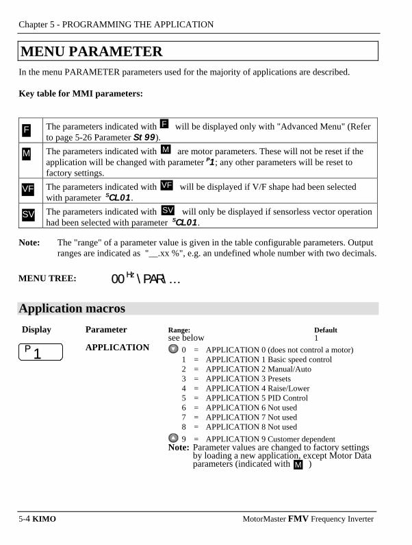
Chapter 5 - PROGRAMMING THE APPLICATION
5-4 KIMO MotorMaster FMV Frequency Inverter
MENU PARAMETER In the menu PARAMETER parameters used for the majority of applications are described. Key table for MMI parameters:
The parameters indicated with will be displayed only with "Advanced Menu" (Refer to page 5-26 Parameter St99).
The parameters indicated with are motor parameters. These will not be reset if the application will be changed with parameter P1; any other parameters will be reset to factory settings.
The parameters indicated with will be displayed if V/F shape had been selected with parameter SCL01.
The parameters indicated with will only be displayed if sensorless vector operation had been selected with parameter SCL01.
Note: The "range" of a parameter value is given in the table configurable parameters. Output
ranges are indicated as "__.xx %", e.g. an undefined whole number with two decimals. MENU TREE: 00 Hz \PAR\… Application macros
Display Parameter Range: Default see below 1 P 1
APPLICATION 0 = APPLICATION 0 (does not control a motor) 1 = APPLICATION 1 Basic speed control 2 = APPLICATION 2 Manual/Auto 3 = APPLICATION 3 Presets 4 = APPLICATION 4 Raise/Lower 5 = APPLICATION 5 PID Control 6 = APPLICATION 6 Not used 7 = APPLICATION 7 Not used 8 = APPLICATION 8 Not used
9 = APPLICATION 9 Customer dependent Note: Parameter values are changed to factory settings
by loading a new application, except Motor Data parameters (indicated with )
F
M
VF
SV
M
F
VF
SV
M

Chapter 5 - PROGRAMMING THE APPLICATION
MotorMaster FMV Frequency Inverter KIMO 5-5
Maximum and minimum speed
Display Parameter Range from: to: Default 7,5 Hz 240,0 Hz 50,0 Hz P 2 MAX SPEED Speed/frequency at maximum setpoint input (100.0 %).
Range from: to: Default -100,0 100,0 % 0,0 % P 3 MIN SPEED Speed/frequency at minimum setpoint input.
A percentage of the MAX SPEED parameter
Ramps
Display Parameter Range from: to: Default 0,0 3000,0 s 10,0 s P 4 ACCEL TIME Time taken to ramp the frequency from 0 Hz to Max
speed Range from: to: Default 0,0 3000,0 s 10,0 s P 5 DECEL TIME Time taken to ramp from max. speed to 0 Hz
Motor current Display Parameter Range from: to: Default see below P 6 MOTOR CURRENT Power range Frequency Inverter set to
0,37 kW 230 V 2,2 A 0,75 kW 230 V 4,0 A 1,5 kW 230 V 7,0 A 0,75 kW 400 V 2,5 A 1,5 kW 400 V 4,5 A 2,2 kW 400 V 5,5 A 3,0 kW 400 V 6,8 A 4,0 kW 400 V 9,0 A 5,5 kW 400 V 12,0 A 7,5 kW 400 V 16,0 A
Base frequency Display Parameter Range from: to: Default 7,5 240,0 Hz 50,0 Hz/60 Hz P 7 BASE FREQUENCY The output frequency at which maximum voltage is
reached. The default depends on Product Code.
M
M
M

Chapter 5 - PROGRAMMING THE APPLICATION
5-6 KIMO MotorMaster FMV Frequency Inverter
Jog setpoint Display Parameter Range from: to: Default -100,0 100,0 % 0,0 % P 8 JOG SETPOINT Speed the Inverter will run at if the Jog input is activated.
A percentage of the MAX SPEED parameter P2
Run Stop selection Display Parameter Range from: to: Default see below 0 P 9 RUN STOP MODE 0 = RAMP
The motor speed is reduced to zero at a rate set by DECEL TIME (P5). A 2 sec pulse is applied at end of ramp
1 = COAST The motor is allowed to freewheel to a stillstand.
2 = INJECTION On a stop command , the motor volts are rapidly
reduced at constant frequency to deflux the motor. A low frequency braking current is then applied until the motor speed is almost zero. This is followed by a timed DC pulse to hold the motor shaft (P5).
V/F shape Display Parameter Range from: to: Default see below 0 P II V/F SHAPE 0 = LINEAR (Linear shape)
Gives a constant flux characteristic up to max. BASE FREQUENCY
1 = QUADRATIC (Quadratic shape)
f
U
100[%]
0
0[Hz] fB
Q
L
Gives a quadratic flux characteristic up to max. BASE FREQUENCY. This matches the load requirements for fan and most pump applications. Refer to P12.

Chapter 5 - PROGRAMMING THE APPLICATION
MotorMaster FMV Frequency Inverter KIMO 5-7
Current Limit Display Parameter Range from: to: Default see below 0 P I2 HEAVY/NORMAL
DUTY 0 = CONSTANT
Current limit is set to = 150 % for 30 sec or 127,5 % for 60 s
1 = QUADRATIC Current limit is set to = 110 % for 10 sec When P 11 is changed from FAN to LINEAR, P 12 is set to 0 (HEAVY). When P 11 is changed from LINEAR to FAN, P 12 is set to 1 (NORMAL). P 12 can be changed independently..
Fixed boost Used to correctly flux the motor at low speeds. This allows the drive to produce greater starting torque for high friction loads. It increases the motor volts above the selected V/F characteristic at the lower end of the speed range. Display Parameter Range from: to: Default 0,00 25,00 % 0,00 % P I3 FIXED BOOST OUTPUT VOLTS
Frequenz f B
25%
100%
BOOST
f B = Eckfrequenz
0% INCREASING
Increased Fluxing torque
CONSTANT POWER RANGE
NORMAL FLUXING
Password Display Parameter Range from: to: Default 0000 FFFF 0000 P 99 PASSWORD A password may be set to prohibit unauthorised adjust-
ment of parameters. When P99 is set to non-zero you will be required to match this value before parameters can be adjusted.
M VF

Chapter 5 - PROGRAMMING THE APPLICATION
5-8 KIMO MotorMaster FMV Frequency Inverter
Speed preset NOTE: These parameters are only displayed if the MACRO 3 is selected with parameter P1. Display Parameter Range from: to: Default -100,00 100,00 0 P 30I PRESET 0 A user-adjustable speed preset set by potentiometer.
-300,00 300,00 20,00 P 302 PRESET 1 Adjustable speed preset
-100,00 100,00 50,00 P 303 PRESET 2 Adjustable speed preset
-100,00 100,00 100,00 P 304 PRESET 3 Adjustable speed preset
-100,00 100,00 -10,00 P 305 PRESET 4 Adjustable speed preset
-100,00 100,00 -20,00 P 306 PRESET 5 Adjustable speed preset
-100,00 100,00 -50,00 P 307 PRESET 6 Adjustable speed preset
-100,00 100,00 -100,00 P 308 PRESET 7 Adjustable speed preset
Ramp function with preset speed This parameters are only visible in the menu when the macro APPLICATION 4 is selected. Display Parameter Range from: to: Default 0,0 600,0 10,0 s P 401 R/L RAMP TIME The time taken to ramp the Raise/Lower output from 0.00
% to 100.00 % of its value. -100,0 100,0 100,0 % P 402 R/L MAX VALUE Maximum value for the ramp output

Chapter 5 - PROGRAMMING THE APPLICATION
MotorMaster FMV Frequency Inverter KIMO 5-9
Display Parameter Range from: to: Default -100,0 100,0 0,0 % P 403 R/L MIN VALUE Minimum value for the ramp output
-100,0 100,0 0,00 % P 404 R/L RESET VALUE The preset speed is reset to the set value of R/L RESET
VALUE when DIN4 (terminal 10) is activated (=24 V)
PID controller PI is used to control the response of any closed loop systems. It is used specifically in systems applications involving the control of drives to provide zero steady state error between setpoint and feedback, together with good transient performance. This parameters are only visible in the menu when the macro APPLICATION 5 is selected in parameter PI. Display Parameter Range from: to: Default 0,00 100,00 1,00 P 50I PI P GAIN Proportional Gain
This is used to adjust the basic response of the closed loop control system. The PI error is multiplied by the Proportional Gain to produce an output.
0,00 100,00 0,00 P 502 PI I GAIN Integral Gain
The Integral term is used to reduce steady state error between the setpoint and feedback values of the PI. If the integral is set to zero, then there will always be steady state error.
P Gain
I Gain
P Gain
d t
d d t
+ Er ror − + +
Out pu t +
Setpoint(AIN1 ) Feed back(AIN2 )
Functions as P, PI controller Single symmetric limit on output

Chapter 5 - PROGRAMMING THE APPLICATION
5-10 KIMO MotorMaster FMV Frequency Inverter
Display Parameter Range from: to: Default 0,00 100,00 0,00 P 503 F
PID D GAIN The PID derivative gain
0,05 s 10,00 s 0,05 s P 504 F
PID D FILTER TC In order to help attenuate high frequency noise on the derivative term, a first order lag has been provided. This parameter determines the filter time constant.
-10,00 10,00 1,00 P 505 F
PID FEEDBACK GAIN
A multiplier applied to the feedback signal of the PID
0,00 % 300,00 % 300,00 % P 506 F
PID LIMIT Determines the maximum positive and negative excursion (Limit) of the PID output.
-3.0000 3.0000 1.0000 P 507
PID SCALING This parameter represents an overall scaling factor which is applied after the PID positive and negative limit clamps.
⎯.xx % ⎯.xx % P 508
PID ERROR The result of SETPOINT − FEEDBACK x FEEDBACK GAIN
⎯.xx % ⎯.xx % P 509
PID OUTPUT The output of the PID function block
F
F
F
F
F
F
F

Chapter 5 - PROGRAMMING THE APPLICATION
MotorMaster FMV Frequency Inverter KIMO 5-11
Method for Setting-up the PI Gains The gains should be set-up so that a critically damped response is achieved for a step change in setpoint. An underdamped or oscillatory system can be thought of as having too much gain, and an overdamped system has too little.
Output Setpoint
Underdamped (oscillatory) Crit ically damped Overdamped
• •
•
To set up the P gain, set the I gain to zero. Apply a step change in setpoint that is typical for the System, and observe the response. Increase the gain and repeat the test until the system becomes oscillatory.
At this point, reduce the P gain until the oscillations disappear. This is the maximum value of P gain achievable. If a steady state error is present, i.e. the feedback never reaches the setpoint value, the I gain needs to be increased. As before, increase the I gain and apply the step change. Monitor the output. If the output becomes oscillatory, reduce the P gain slightly. This should reduce the steady state error. Increasing the I gain further may reduce the time to achieve zero steady state error.

Chapter 5 - PROGRAMMING THE APPLICATION
5-12 KIMO MotorMaster FMV Frequency Inverter
MENU DIAGNOSTICS
MENU TREE: 0.0 Hz \diA9\… The menu DIAGNOSTICS customs useful parameters for diagnostics. Refer to Chapter 6 for more details.
MENU CTRL
MENU TREE: 0.0 Hz \SEt\CtRL\… Display Parameter Range from: to: Default 0 1 0 SCL0I
CONTROL MODE 0 = VOLTS/HZ 1 = SENSORLESS VEC This parameter contains the main method of motor control used by the drive.
0.1 30000.0 RPM see below SCL02
NAMEPLATE RPM This parameter contains the motor nameplate full-load rated speed. This is the motor speed in rpm at base frequency minus full load slip (product code dependent)
0 1 0 SCL03
FLY-CATCH ENABLE
0 = FALSE 1 = TRUE - Enables flycatching in Sensorless Vector control mode when TRUE. Allows the drive to catch a spinning load.
0 1 0 SCL04
SLIP COMP ENABLE
0 = FALSE 1 = TRUE - Slip compensation is operational when TRUE. Eliminates motor speed variations under load conditions in V/F Fluxing Mode when the correct value for MAG CURRENT is entered into SCL14
0 1 1 SCL05
STABILISATION ENABLE
0 = FALSE 1 = TRUE - Enables the stabilisation function when TRUE. Eliminates light load speed variations in V/F Fluxing Mode.
M
SV
VF
VF

Chapter 5 - PROGRAMMING THE APPLICATION
MotorMaster FMV Frequency Inverter KIMO 5-13
Display Parameter Range from: to: Default 0 2 0 SCL06
VOLTAGE CONTROL MODE
Control of output voltage independent of d.c. link voltage. 0 = NONE No attempt is made to control the PWM
modulation depth for variations in dc link voltage.
1 = FIXED The drive's output volts are maintained, regardless of variations in the dc link voltage. The drive's product code sets the default value for demanded maximum output voltage (see MOTOR VOLTAGE below).
2 = AUTOMATIC- The drive performs controlled over-fluxing during motor deceleration.
Range from: to: Default 0 1 0 SCL07
BOOST MODE Determines the relationship between fixed boost and terminal volts. 0 = FALSE Standard mode.
Produces the terminal volts profile shown below (with Auto Boost set to 0.0 %). In this mode AUTO BOOST (CL08) should also be set to provide optimum low speed performance..
1 = TRUE Advanced mode. Emulates the terminal volts profile provided by the MM1/2 inverter. This allows drop in replacement of the MM1/2 by the MM FMV. AUTO BOOST (SCL08) has no effect in this mode.
100%
BASE
Simple Mode (CL07 = 1)
Advanced Mode (CL07 = 0)Output Frequency
MotorTerminal
Volts
BOOST %FIXED
FREQUENCY
VF
F VF

Chapter 5 - PROGRAMMING THE APPLICATION
5-14 KIMO MotorMaster FMV Frequency Inverter
Display Parameter Range from: to: Default 0.00 % 25.00 % 0.00 % SCL08
AUTO BOOST This parameter allows for load dependent, stator resistance voltage-drop compensation. This correctly fluxes the motor (under load conditions) at low output frequencies, thereby increasing available motor torque.. AUTO BOOST is only used when BOOST MODE is set to 0. The value of the AUTO BOOST parameter determines the level of additional volts supplied to the motor for 100% load. Setting the value of AUTO BOOST too high can cause the drive to enter current limit. If this occurs, the time taken for the drive to reach operating speed will be extended. Reducing the value of AUTO BOOST will eliminate this problem..
Range from: to: Default 0 1 0 SCL09
ENERGY SAVING 0 = FALSE 1 = TRUE The demanded volts are reduced to
minimise energy consumption if the drive is operating in a steady state at light load
Range from: to: Default 0.01 A 999.99 A see below SCLI0
MOTOR CURRENT Motor nameplate full-load line current (product code dependent)
Range from: to: Default siehe unten 4 SCLII
MOTOR POLES 2 = 2 pole Number of motor poles, as supplied 4 = 4 pole on the motor nameplate 6 = 6 pole 8 = 8 pole 10 = 10 pole 12 = 12 pole
Range from: to: Default 0.0 V 575.0 V see below SCLI2
MOTOR VOLTAGE Motor nameplate voltage at base frequency
Range from: to: Default 0.01 A 999.99 A see below SCLI4
MAG CURRENT Motor model no-load line current as determined by the Autotune, or taken from the motor nameplate
MF VF
F VF
M SV
M SV
M
M

Chapter 5 - PROGRAMMING THE APPLICATION
MotorMaster FMV Frequency Inverter KIMO 5-15
Display Parameter Range from: to: Default 0.00 kW 355.00 kW see below SCLI5
POWER Motor nameplate power
Range from: to: Default 0 1 1 SCLI6
MOTOR CONNECTION
0 = DELTA 1 = STAR Motor nameplate connection.
Range from: to: Default 0.0000 Ω 250.0000 Ω see below SCLI7
STATOR RES Motor model per-phase stator resistance as determined by Autotune
Range from: to: Default 0.00 mH 300.00 mH see below SCLI8
LEAKAGE INDUC Motor model per-phase leakage inductance as determined by Autotune
Range from: to: Default 0.00 mH 300.00 mH see below SCLI9
MUTUAL INDUC Motor model per-phase mutual inductance as determined by Autotune
Range from: to: Default 10.00 ms 3000.00 ms see below SCLIA
ROTOR TIME CONST
Motor model rotor time constant as determined by Autotune
Range from: to: Default 0 1 0 SCL20
AUTOTUNE MODE Selects the Autotune operating mode: 0 = STATIONARY 1 = ROTATING
Range from: to: Default 0 1 0 SCL2I
AUTOTUNE ENABLE
Determines whether the Autotune sequence is operational or not: 0 = FALSE 1 = TRUE - The Autotune sequence is operational
when the drive is run
M SV
M SV
M SV F
M SV F
M SV F
M SV F
SV
SV

Chapter 5 - PROGRAMMING THE APPLICATION
5-16 KIMO MotorMaster FMV Frequency Inverter
Display Parameter Range from: to: Default 0.00 % 300.00 % 300.00 % SCL8I
CURRENT LIMIT This parameter sets the level of motor current, as a % of MOTOR CURRENT (SCL10) at which the drive begins to take current limit action.
Range from: to: Default -500.0 % 500.0 % 200.0 % SCL82
POS TORQUE LIMIT
This parameter sets the maximum allowed level of positive motor torque.
Range from: to: Default -500.0 % 500.0 % 200.0 % SCL83
NEG TORQUE LIMIT
This parameter sets the maximum allowed level of negative motor torque.
Range from: to: Default 0 1 1 SCL84
STALL TRIP TYPE This parameter determines whether the stall trip operates on motor torque or motor current: 0 = FALSE TORQUE 1 = TRUE CURRENT
Range from: to: Default 0.00 300.00 see below SCL9I
SPEED PROP GAIN Sets the proportional gain of the loop. Speed error (revolutions per second) x proportional gain = torque percent.
Range from: to: Default 1 ms 15000 ms see below SCL92
SPEED INT TIME This is the integral time constant of the speed loop. A speed error which causes the proportional term to produce a torque demand T, will cause the integral term to also ramp up to a torque demand T after a time equal to “speed int time”.
Range from: to: Default -110.00 % 110.00 % 110.00 % SCL93
SPEED POS LIMIT This sets the upper limit of the speed demand.
Range from: to: Default -110.00 % 110.00 % -110.00 % SCL94
SPEED NEG LIMIT This sets the lower limit of the speed demand.
F
F
F
F
M SV F
SV F
SV F
M SV F

Chapter 5 - PROGRAMMING THE APPLICATION
MotorMaster FMV Frequency Inverter KIMO 5-17
MENU SETUP NOTE: Control terminal 10 DIN4 / DOUT2 can be used as Digital Input DIN4 or Digital Output
DOUT2.
Input Menu
MENU TREE: 00 Hz \SEt\In\…… Digital Inputs Display Parameter Range from: to: Default 0 1 0 S iP0i DIN 1 INVERT Inverts the value of the signal, TRUE or FALSE
0 = not inverted 1 = inverted
0 1 0 S iP02 DIN 2 INVERT as S iP01
0 1 0 S iP03 DIN 3 INVERT as S iP01 0 1 0 S iP04 DIN 4 INVERT as S iP01 0 1 0 S iP05 DIN 5 INVERT as S IP0I 0 1 0 S iP06 DIN 6 INVERT as S IP0I 0 1 0 S iP07 DIN 7 INVERT as S IP0I
To use the terminal 10 as Digital Input the parameters S OP2i and S OP22 must be set to "0". To invert the logic of the Digital Input the parameter S IP04 must be set to "1".

Chapter 5 - PROGRAMMING THE APPLICATION
5-18 KIMO MotorMaster FMV Frequency Inverter
Analog Inputs Display Parameter Range from: to: Default -300,00 % 300,00 % 100,00 % S IPii AIN1 SCALE
VALUE+SCALE OFFSET
XINPUT
TYPE
UNPROCESSED
0 to 100% of selected TYPE Range from: to: Default -300,00 % 300,00 % 0,00 % S IPi2 AIN 1 OFFSET Display Parameter Range from: to: Default 0 1 0 S IPi3 AIN 1 TYPE 0 = 0-10 V
1 = 0-5 V Range from: to: Default -300,00 % 300,00 % 100,00 % S IP2i AIN 2 SCALE
Range from: to: Default -300,00 % 300,00 % 0,00 % S IP22 AIN 2 OFFSET
Range from: to: Default 0 3 3 S IP23 AIN 2 TYPE 0 = 0-10 V
1 = 0-5 V 2 = 0-20 mA
3 = 4-20 mA Range from: to: Default 0 = FALSE 1 = TRUE 0 = FALSE S IPdi DIN1 VALUE Displays the status of the digital input 1
F Range from: to: Default 0 = FALSE 1 = TRUE 0 = FALSE S
IPd2 DIN2 VALUE Displays the status of the digital input 2
F Range from: to: Default 0 = FALSE 1 = TRUE 0 = FALSE S
IPd3 DIN3 VALUE Displays the status of the digital input 3
F

Chapter 5 - PROGRAMMING THE APPLICATION
MotorMaster FMV Frequency Inverter KIMO 5-19
Display Parameter Range from: to: Default 0 = FALSE 1 = TRUE 0 = FALSE S
IPd4 DIN4 VALUE Displays the status of the digital input 4
F Range from: to: Default 0 = FALSE 1 = TRUE 0 = FALSE S
IPd5 DIN5 WERT Displays the status of the digital input 5
F Range from: to: Default
0 = FALSE 1 = TRUE 0 = FALSE S
IPd6 DIN6 WERT Displays the status of the digital input 6
F Range from: to: Default
0 = FALSE 1 = TRUE 0 = FALSE S
IPd7 DIN7 WERT Displays the status of the digital input 7
F Range from: to: Default
–.x % –.x % S
IPAi AIN1 VALUE Displays the status of the digital output AIN1 with offset and scaling applied.
F Range from: to: Default –.x % –.x % S
IPA2 AIN2 VALUE Displays the status of the digital output AIN2 with offset and scaling applied.
F
Output-Menu
MENU TREE: 00 Hz \SEt\0ut\…… Analog Output Display Parameter Range from: to: Default 0 4 1 S OP0i AOUT 1 SOURCE ANALOG OUTPUT
0 = NONE 1 = DEMAND %
2 = CURRENT % 3 = PI ERROR %
4 = RAISE/LOWER OUTPUT %

Chapter 5 - PROGRAMMING THE APPLICATION
5-20 KIMO MotorMaster FMV Frequency Inverter
Display Parameter Range from: to: Default -300,00 % 300,00 % 100,00 % S 0P02 AOUT 1 SCALE
+SCALE OFFSET
XVALUE
ABS
X
OUTPUT
100%
0%
CLAMP
Range from: to: Default -300,00 % 300,00 % 0,00 % S 0P03 AOUT 1 OFFSET
Range from: to: Default 0 1 0 S 0P04 AOUT 1 TYPE 0 = not absolute
1 = absolute Bereich von: bis: Werkseinstellung -300.0 % 300.0 % 0.0 % S 0P05 AOUT 1 VALUE
Digital Outputs Display Parameter Range from: to: Default 0 5 0 S 0P2i DIN4/
DOUT 2 SOURCE DIN4/DOUT2
0 = NONE 1 = HEALTH
2 = TRIPPED 3 = RUNNING 4 = AT ZERO 5 = AT SPEED
6 = AT LOAD as S 0P31 Range from: to: Default 0 1 0 S 0P22 DIN4/
DOUT 2 INVERT 0 = not inverted 1 = inverted
as S iP0i Set to 0 in APPLICATION MACROS 1 & 5 Bereich von: bis: Werkseinstellung 0 FALSE 1 TRUE 0 FALSE S 0P23 DOUT 2 VALUE The TRUE or FALSE output demand.
To use the terminal 10 as Digital Output the parameter S OP2i must be set to "1, 2, 3, 4, 5 or 6". To invert the logic of the Digital Output the parameter S OP22 must be set to "1".
F
F

Chapter 5 - PROGRAMMING THE APPLICATION
MotorMaster FMV Frequency Inverter KIMO 5-21
Relay Output Display Parameter Range from: to: Default 0 5 1 S 0P3I RELAY SOURCE Relay
0 = NONE Relay is open 1 = HEALTH
The run signal is not present, or no trip is active 2 = TRIPPED Relay is closed A trip is present 3 = RUNNING Motor is running 4 = AT ZERO The output frequency is below 1 % of max. speed (P2), with 1 % hysteresis
5 = AT SPEED The output frequency is within 1 % of max speed (P2), with 1 % hysteresis
6 = AT LOAD The magnitude of the output torque is greater than or equal to the torque level set in S St42
Range from: to: Default 0 1 0 S 0P32 RELAY INVERT as S iP01
Range from: to: Default 0 1 S 0P33 RELAIS VALUE Shows whether the relay is activated.
Trip Menu
MENU TREE: 0.0 Hz \SEt\trip\…… Display Parameter Range from: to: Default 0 1 1 S loop DISABLE LOOP 0 = Trip enabled
1 = Trip disabled Range from: to: Default 0 1 0 S t 3 AIN2 OVERLOAD
0 = enabled Disables the overload trip1 = Alarm disabled (Terminal 3)
Range from: to: Default 0 1 0 S stll DISABLE STALL 0 = enabled
1 = disabled
F

Chapter 5 - PROGRAMMING THE APPLICATION
5-22 KIMO MotorMaster FMV Frequency Inverter
Display Parameter Range from: to: Default 0 1 0 S 0t DISABLE MOTOR
OVERTEMP 0 = enabled 1 = disabled
Range from: to: Default 0 1 0 S It I*T INVERSE TIME 0 = enabled
1 = disabled Range from: to: Default 0 1 1 S db r DYNAMIK BRAKE
RESISTOR as S loop
Range from: to: Default 0 1 1 S db S DYNAMIK BRAKE
SWITCH as S loop
Range from: to: Default 0 1 0 S SPd SPEED FEEDBACK as S loop
Range from: to: Default 0 1 0 S OSPd OVERSPEED 0 as S loop
Range from: to: Default 0 1 0 S dIsP DISPLAY (KEYPAD) 0 = enabled
1 = disabled SERL Menu
MENU TREE: 0.0 Hz \SEt\serl\…… The SERL Menu is only visible if the parameter ST99 is set to "1". Display Parameter Range from: to: Default 0 1 0 S SE0I REMOTE COMMS
SEL 0 = FALSE Control is from the terminals 1 = TRUE Control is from the communications
F Type of control if REMOTE MODE is selected Range from: to: Default 0.0 600.0 s 0.0 s S SE02 COMMS-TIMEOUT Sets the maximum time allowed between refreshing the
COMMS COMMAND parameter. F The drive will trip if this time is exceeded. Set the time to
0.00 seconds to disable this feature.

Chapter 5 - PROGRAMMING THE APPLICATION
MotorMaster FMV Frequency Inverter KIMO 5-23
Display Parameter Range from: to: Default 0 255 0 S SE03 COMMS ADDRESS The drives identity address.
Note: If set to 0, it will only respond to broadcast F messages
Display Parameter Range from: to: Default 0 8 0 S SE04 BAUD RATE 0 = 1200
1 = 240 5 = 14400 6 = 19200
F 2 = 4800 7 = 38400 3 = 7200
4 = 9600 8 = 57600
Selects the Baud Rate for the MODBUS protocol Range from: to: Default 0 2 0 S SE05 PARITY 0 = NONE
1 = ODD F 2 = EVEN
Selects the Parity for the MODBUS protocol. Range from: to: Default 0 200 5 ms S SE06 REPLY DELAY ms The time in milliseconds between the drive receiving the
complete request from the communications master F (PLC/PC) and replying to this request.
Range from: to: Default 0 4 0 S SE07 OP PORT
PROTOCOL 0 = AUTOMATIC
1 = KEYPAD F 2 = EIBISYNC ASCII
3 = MODBUS 4 = FIELDBUS
FIELDBUS is reserved for future use. Selects the protocol to be used by the keypad port on the front of the drive. When EIBISYNC ASCII is selected, BAUD RATE is 19200 and PARITY is EVEN.
Range from: to: Default 0 4 0 S SE08 P3 PORT PROTOCOL 0 = AUTOMATIC
1 = KEYPAD F 2 = EIBISYNC ASCII
3 = MODBUS 4 = FIELDBUS
Selects the protocol to be used by the RS232 programming port on the drive's control board. When EIBISYNC ASCII is selected, BAUD RATE is 19200 and PARITY is EVEN. FIELDBUS is reserved for future use. NOTE: These parameter is only suitable, if the
Frequency Inverter is delivered with an integrated RS232 programming port.

Chapter 5 - PROGRAMMING THE APPLICATION
5-24 KIMO MotorMaster FMV Frequency Inverter
Diverse Setup Menu
MENU TREE: 0.0 Hz \SEt\setp\…… Display Parameter Range from: to: Default 0,0 s 3000,0 s 1,0 s S st0I JOG ACCEL TIME as P4, for jog
Range from: to: Default 0,0 s 3000,0 s 1,0 s S st02 JOG DECEL TIME as P5, for jog
Range from: to: Default 0 = LINEAR 1 = S 0 S st03 RAMP TYPE Selects the ramp type
Range from: to: Default 0,01 s3 100,00 s3 10,0 sec3 S st04 S RAMP JERK Rate of change of acceleration of the curve in units per
sec3 Range from: to: Default
0 = FALSE 1 = TRUE 1 S st05 S RAMP
CONTINOUS When TRUE and the S ramp is selected, forces a smooth transition if the speed setpoint is changed when ramping.
The curve is controlled by the S RAMP JERK parameter. When FALSE, there is an immediate transition from the
old curve to the new curve. Range from: to: Default 0 = PROP.W/MIN 1= LINEAR 0 S st06 MIN SPEED MODE Processing of setpoint:
0 = PROP.W/MIN 1 = LINEAR MAX
0
Ausgang
100 %
MINEingang
MAX
0
Ausgang
100 %MIN
Eingang
Range from: to: Default 0,0 Hz 240,0 Hz 0,0 Hz S stII SKIP FREQUENCY 1 Centre frequency of skip band 1
Range from: to: Default 0,0 Hz 60,0 Hz 0,0 Hz S stI2 SKIP FREQUENCY
BAND 1 Width of skip band 1
Range from: to: Default 0,0 Hz 240,0 Hz 0,0 Hz S stI3 SKIP FREQUENCY 2 Centre frequency of skip band 2
Range from: to: Default 0,0 Hz 60,0 Hz 0,0 Hz S stI4 SKIP FREQUENCY
BAND 2 Width of skip band 2

Chapter 5 - PROGRAMMING THE APPLICATION
MotorMaster FMV Frequency Inverter KIMO 5-25
Auto restart Display Parameter Range from: to: Default 0 10 0 S st2I AUTO RESTART
ATTEMPTS Determines the number of restarts that will be permitted before requiring an external fault reset
Range from: to: Default 0,0 600,0 s 10,0 s S st22 AUTO RESTART
DELAY Determines the delay between restart attempts for a trip included in AUTO RESTART TRIGGERS and AUTO RESTART TRIGGERS+. The delay is measured from all error conditions clearing.
Range from: to: Default 0x000 0xFFFF 0x0000 S st23 AUTO RESTART
TRIGGERS Allows AUTO RESTART to be enabled for a selection of trip conditions. Refer to page 6-5 - Hexadecimal representations of trips.
Range from: to: Default 0x000 0xFFFF 0x0000 S st24 AUTO RESTART
TRIGGERS+ Allows AUTO RESTART to be enabled for a selection of trip conditions. Refer to page 6-5 - Hexadecimal
representations of trips. Range from: to: Default 0 = FALSE 1 = TRUE 1 S st3I DB ENABLE Enables operation of the dynamic braking.
Range from: to: Default S st32 DB RESISTANCE 1 1000 Ω see below
The value of the load resistance (product code dependent) Range from: to: Default 0.1 kW 510.0 kW see below S st33 DB POWER Product code dependent
Range from: to: Default S st34 DB OVERRATING 1 40 25
Power overloads lasting no more than 1 s Range from: to: Default ⎯.xx % ⎯.xx % ⎯.xx % S st4I TORQUE FEEDBACK Shows the estimated motor torque, as a percentage of
rated motor torque. Range from: to: Default -300.0 % 300.0 % 100.0 % S st42 TORQUE LEVEL Sets the value of load at which AT LOAD becomes
TRUE. See S OP2I and S OP3I.

Chapter 5 - PROGRAMMING THE APPLICATION
5-26 KIMO MotorMaster FMV Frequency Inverter
Display Parameter Range from: to: Default 0 = FALSE 1 = TRUE 0 S st43 USE ABS TORQUE 0 = FALSE The direction of rotation is not ignored.
Driving a load in the reverse direction gives a negative value for torque. In this case, the comparison level may be positive or negative.
1 = TRUE The direction of rotation is ignored. In this case, the comparison level should always be positive.
Range from: to: Default 0.0 100.0 % 0.0 % S st51 LOCAL MIN SPEED The magnitude of the minimum setpoint that will be used
when running in Local Mode. Range from: to: Default 0000 FFFF FFFF S st52 ENABLED KEYS The following keys on the MM O-FeP-PROG1 keypad
can be enabled or disabled separately. The combination produces the parameter setting as in the table below. The default of FFFF enables all keys.
Parameter Setting
RUN L/R JOG DIR
0000 0010 0020 0030 0040 0050 0060 0070 0080 0090 00A0 00B0 00C0 00D0 00E0 00F0
- - - - - - - - ENABLED ENABLED ENABLED ENABLED ENABLED ENABLED ENABLED ENABLED
- - - - ENABLED ENABLED ENABLED ENABLED - - - - ENABLED ENABLED ENABLED ENABLED
- - ENABLED ENABLED - - ENABLED ENABLED - - ENABLED ENABLED - - ENABLED ENABLED
- ENABLED - ENABLED - ENABLED - ENABLED - ENABLED - ENABLED - ENABLED - ENABLED
When using the standard MM O-FM-PROG-TTL and MM O-FEV-PROG keypad, disabling the DIR key prevents the local setpoint going negative (for reverse). Similarly, disabling the L/R key prevents the drive being changed from Local to Remote, or Remote to Local modes.
Range from: to: Default 0 = FALSE 1 = TRUE 0 S st98 APPLICATION
LOCK Setting this parameter to TRUE prevents editing of parameter P1. Set this parameter to FALSE to edit parameter P1
Range from: to: Default 0 = PARTIAL 1 = FULL 0 S st99 MENU DETAIL Selects FULL or PARTIAL menu detail. The additional
parameters in the FULL menus are indicated with F .
F
F
F
F

Chapter 5 - PROGRAMMING THE APPLICATION
MotorMaster FMV Frequency Inverter KIMO 5-27
Skip frequencies Two programmable skip frequencies are available to avoid resonances within the mechanical system. Enter the value of frequency that causes the resonance using the FREQUENCY parameter and then programme the width of the skip band using its BAND parameter. The Inverter will then avoid sustained operation within the forbidden band as shown in the diagram.
Drive Frequency
Skip band
Skip Frequency Setpoint
Drive Frequency
SetpointFrequency 1 Frequency 2
Drive Frequency
SetpointFrequency 1 Frequency 2

Chapter 5 - PROGRAMMING THE APPLICATION
5-28 KIMO MotorMaster FMV Frequency Inverter
MENU ENCODER Display Parameter Range from: to: Default 0 2 0 S EN0I ENC MODE Set this parameter to the requirements for your encoder:
0 = QUADRATURE (Digital inputs 6 & 7,ENCA and ENCB respectively).
1 = CLOCK/DIR (Digital inputs 6 & 7, ENCA and ENCB respectively).
2 = CLOCK (Digital input 6, ENCA) Range from: to: Default 0 = FALSE 1 = TRUE 0 S EN02 ENC RESET 1 = TRUE POSITION and SPEED outputs are set (and
held) at zero Range from: to: Default 0 = FALSE 1 = TRUE 0 S EN03 ENC INVERT 1 = TRUE Changes the sign of the measured speed and the
direction of the position count Range from: to: Default 100 1000 100 S EN04 ENC LINES The number of lines must be set to match the type of
encoder being used. Incorrect setting of this parameter will result in an erroneous speed measurement.
Range from: to: Default 0.00 300.00 1.00 S EN05 ENC SPEED SCALE This parameter allows the output "speed" to be scaled to
any value the user requires. With setting: 1.00 output is in revs per second 60.00 output is in revs per minute To provide an output in percent of the motor maximum speed, where maximum speed is the maximum speed your motor will run in rpm, the ENC SPEED SCALE parameter should be set to the result of:
ENC SPEED SCALE = 6000 maximum speed (rpm)
Range from: to: Default ⎯.x ⎯.x S EN06 ENC SPEED Speed feedback, in units defined by S EN05 .
F
F
F
F
F
F
Chapter 6 - TRIPS, DIAGNOSTICS AND FAULT FINDING
MotorMaster FMV Frequency Inverter KIMO 6-1
Chapter 6 - TRIPS, DIAGNOSTICS AND FAULT FINDING
Page INTRODUCTION.....................................................................................................................6-2
Trip warning message...................................................................................6-2 When a trip occurs ........................................................................................6-2 Resetting a trip ..............................................................................................6-2 Using the Operator Station to manage trips..................................................6-2
TRIPS........................................................................................................................................6-3 MAIN MENU - DIAGNOSTICS..............................................................................................6-7 OTHER FAULT FINDING ......................................................................................................6-8

Chapter 6 - TRIPS, DIAGNOSTICS AND FAULT FINDING
6-2 KIMO MotorMaster FMV Frequency Inverter
INTRODUCTION The MM FMV Frequency Inverters provide comprehensive diagnostic, alarm and trip facilities. These facilities minimise the possibility of damage to the frequency inverter, motor and associated components under unusual or fault conditions. The diagnostics information, available at the operating panel, enables ready identification of these conditions. In the event that a fault is traced to the Frequency Inverter, then the inverter should be returned to the supplier - no corrective maintenance should be attempted (see Chapter 7, SERVICING). The following diagnostic information is available with MM FMV Frequency Inverters: Trip warning message The trip display message is flashed repeatedly on the screen to warn of an imminent trip. Some trip conditions need time to take effect. The warning can allow you time to rectify the situation. The message will clear when the Operator Station is used, but after a short time will reappear until the problem is resolved, or the drive trips. When a trip occurs When a trip occurs, the Inverter's power stage is immediately disabled causing the motor and load to coast to a stop. The trip is latched until action is taken to reset it. This ensures that trips due to transient conditions are captured and the Inverter is disabled, even when the original cause of the trip is no longer present. Resetting a trip All trips must be reset before the Inverter can be re-enabled. A trip can only be reset once the trip condition is no longer active, i.e. a trip due to a heatsink over-temperature will not reset until the temperature is below the trip level. A trip can be reset as follows: 1. Press the key to reset the trip and clear the alarm form the display. 2. Remove and then re-apply the RUN command and the drive will run normally.
Success is indicated by either rdy or the Local Setpoint being displayed. Using the Operator Station to manage trips Trip Messages If the Inverter trips, then the display immediately shows a message indicating the reason for the trip. The possible trip messages are given in the table below.

Chapter 6 - TRIPS, DIAGNOSTICS AND FAULT FINDING
MotorMaster FMV Frequency Inverter KIMO 6-3
TRIPS Display Trip Message Meaning - Possible Cause for trip AdCHI DCLINKHIGH The Inverter internal dc link voltage is too high
- The supply voltage is too high - Trying to decelerate a large inertia load too quickly,
DECEL TIME time too short. - The brake resistor is open circuit (400 V unit only)
AdCL0 DCLINK LOW - DC LINK low trip.
- Supply is too low/power down A 0C
OVERCURRENT The motor current being drawn from the Inverter is too high - Trying to accelerate a large inertia load too quickly;
ACCEL TIME time is too short - Trying to decelerate a large inertia load too quickly;
DECEL TIME time too short. - Application of shock load to motor. - Short circuit between motor phases. - Short circuit between motor phases and earth. - Motor output cables too long or too many parallel
motors connected to the Inverter. - FIXED BOOST level set too high.
AHOt HEATSINK OVER TEMPERATURE
Drive heatsink temperature >10 °C - The ambient air temperature is too high - Poor ventilation or spacing between Inverters
AEt EXTERNAL TRIP External trip input is high. Check configuration to identify the source of the signal (non-standard configuration
ALOOP
LOST LOOP (Disable: S LOOP)
- A current of less than 1 mA is preset when 4-20 mA setpoint is selected - look for a wire break.
AStLL STALL
(Disable: S StLL) The motor has stalled (not rotating). Drive in current limit >200 sec. - Motor loading too great - FIXED BOOST level set too high
At 3 TERMINAL 3
OVERLOAD AIN2 overload - overcurrent applied in Current mode.

Chapter 6 - TRIPS, DIAGNOSTICS AND FAULT FINDING
6-4 KIMO MotorMaster FMV Frequency Inverter
Display Trip Message Meaning - Possible Cause for trip AdISP DISPLAY (keypad) Keypad disconnected from drive whilest drive is running
in Local mode. (Check from second keypad) ASCI
SERIELLE COMMS - Motor failed - Wiring disconnected - Incorrect comms setup
ACNtC CONTACTOR
FEEDBACK - Check wiring - Check terminal wired to "contactor closed" parameter
A Ot MOTOR OVERTEMPERATURE
Motor temperature too high - Excessive load - Incorrect motor voltage rating - Fixed Boost level set too high - Prolonged operation at low speed - Break in motor thermistor connection
AI HI
CURRENT LIMIT Software overcurrent trip - see OVERCURRENT above
ALSPd OVERCURRENT F=0 Motor current >100 % at zero output frequency
FIXED BOOST level set too high At 4 TERMINAL 4
OVERLOAD -10 V REF overload warning -10 mA maximum
AShRt DESTURATION Instantaneous overcurrent, refer to OVERCURRENT
AdCRP DC LINK RIPPLE A dc link ripple alert
- Supply imbalance in a 3-phase system - Poor supply regulation an a 1-phase system
AdbSC DYNAMIC BRAKE
SHORT - Brake resistor overcurrent - Brake resistor value is greater than minimum allowed
At 5 TERMINAL 5
OVERLOAD AOUT1 overload-10 mA maximum
At 9 TERMINAL 9
OVERLOAD DIN3 overload -20 mA maximum
At I0 TERMINAL 10
OVERLOAD DIN4/DOUT2 overload -50 mA maximum

Chapter 6 - TRIPS, DIAGNOSTICS AND FAULT FINDING
MotorMaster FMV Frequency Inverter KIMO 6-5
Display Trip Message Meaning - Possible Cause for trip AtRIP UNKNOWN TRIP Unknown trip
AtR32 OTHER Other trip is active (Trip ID33)
AICAL
ZERO I CURRENT CALIBRATION
Current sensor calibration fault. Switch inverter off/on. If persistent, return inverter to supplier
ACOdE PRODUCT CODE ERROR
Switch inverter off/on. If persistent, return inverter to supplier
ACal
CALIBRATION DATA ERROR
Switch inverter off/on. If persistent, return inverter to supplier
AdAtA CONFIGURAT DATA
ERROR Switch inverter off/on. If persistent, return inverter to supplier
Hexadecimal Representation of Trips The tables below show the possible parameter values for the AUTOMATIC RESTART TRIGGERS and the AUTOMATIC RESTART TRIGGERS+ (Parameter SST23 and SST24)
ID Display Trip Name Mask Disable Description 0 NO ALARM 0x0000 N/A No trip present 1 DCHI OVERVOLTAGE 0x0001 Over voltage 2 DCLO UNDERVOLTAGE 0x0002 Under voltage 3 OC OVERCURRENT 0x0004 Over current 4 HOT HEATSINK 0x0008 x Heatsink over-temperature 5 ET EXTERNAL TRIP 0x0010 x External trip 7 LOOP LOOP 0x0080 x AIN2 current input signal >1 mA 8 STLL MOTOR STALLED 0x0100 x Motor stalled 9 T3 AIN2 FAULT (T3) 0x8000 x Terminal 3: AIN2 overload (>22 mA) 13 SCI DISPLAY / KEYPAD 0x1000 x Comms watchdog timeout when in
remote comms mode 14 CNTC CONTACTOR FBK 0x2000 x Contactor feedback (external contactor
not closed within allowed time)

Chapter 6 - TRIPS, DIAGNOSTICS AND FAULT FINDING
6-6 KIMO MotorMaster FMV Frequency Inverter
ID Display Trip Name Mask Disable Description 17 0T MOTOR OVERTEMP 0x0001 x Motor over temperature 18 IHI CURRENT LIMIT 0x0002 x High current >180 % for 1 second 21 LSPD LOW SPEED OVER I 0x0010 x Motor current >100 % with
frequency = 0 22 T4 10VREF (T4) 0x0020 x Terminal 4: 10 V output overload
WARNING ONLY! 24 SHRT SHORT CIRCUIT 0x0080 x Short circuit on motor output 25 DCRP VDC RIPPLE 0x0100 x DC ripple 26 DBSC BRAKE SHORT
CIRCUIT 0x0200 x Short circuit across dynamic brake
resistor 28 T5 AOUT1 0x0800 x Terminal 5: Analog output overload
WARNING ONLY! 29 T9 DIN3 0x1000 x Terminal 9: Digital output overload 30 T10 DIN4/DOUT2 0x2000 x Terminal 10: Digital output
overload 31 TRIP UNKNOWN 0x4000 Unknown trip 33 ICAL CURRENT CALIB 0x8000 Zero current calibration
When more than one trip is to be represented at the same time then the trip codes are simply added together to form the value displayed. Within each digit, values between 10 and 15 are displayed as letter A to F (e.g. 11 = the letter B). Example: In parameter AUTOMATIC RESTART TRIGGERS 00C3 is displayed: 2 1 Value of correcting variable 0 0 C 3 No 3 = added from: 1 = Over voltage *
2 = Under voltage * Letter C = Value 12, added from: 8 = Motor stalled *
4 = Loop * * refer to table Hexadecimal Representation of Trips

Chapter 6 - TRIPS, DIAGNOSTICS AND FAULT FINDING
MotorMaster FMV Frequency Inverter KIMO 6-7
MAIN MENU - DIAGNOSTICS Display Trip Message Meaning - Possible Cause for trip
0.0Hz FREQUENCY Output frequency in Hz
0.0% SPEED SPT The set point as a percentage MAX SPEED (Max. speed)
0.0 V DC LINK VOLTS Vac √2 = DC link volts
0.0 A MTR CURRENT The current load value in Amps

Chapter 6 - TRIPS, DIAGNOSTICS AND FAULT FINDING
6-8 KIMO MotorMaster FMV Frequency Inverter
OTHER FAULT FINDING Problem Possible Cause Cure Inverter will not power up ♦ Fuse blown
♦ Faulty cabling
- Check supply details, replace with correct fuse
- Check all connections are correct and secure
- Check cable continuity
Inverter fuse keeps blowing
♦ Faulty cabling or connections wrong
♦ Faulty inverter
- Check for problem and rectify before replacing with correct fuse
- Contact your supplier
Cannot obtain HEALTH state
♦ Incorrect or no supply available - Check supply details
Motor will not run at switch-on
♦ Motor jammed - Stop the inverter and clear the jam
Motor runs and stops ♦ Motor becomes jammed - Stop the inverter and clear the jam
Motor runs at full speed only
♦ Reversed tachogenerator or open circuit tachogenerator
♦ Open circuit speed reference potentiometer
- Check tachogenerator connections
- Check connections
Motor runs in wrong direction
♦ Motor connection incorrect - Reverse two phases

Chapter 7 -SERVICING
MotorMaster FMV Frequency Inverter KIMO 7-1
Chapter 7 - SERVICING Page MAINTENANCE......................................................................................................................7-2 REPAIR.....................................................................................................................................7-2 SAVING APPLICATION DATA BEFORE RETURNING EQUIPMENT ............................7-2 RETURNED EQUIPMENT......................................................................................................7-3 DISPOSAL................................................................................................................................7-3

Chapter 7 - SERVICING
7-2 KIMO MotorMaster FMV Frequency Inverter
MAINTENANCE MM FMV Frequency Inverters are practically free of maintenance. However the following should be periodically inspected: Cooling system: - Is the fan in operation? - Make sure cooling inlets of the enclosure are free from obstructions and dust
build-up? - As previous for cooling outlets - Verify that cooling air can circulate freely and that adequate enclosure cooling
is available Mounting: - Make sure the MM FMV Frequency Inverter is securely mounted Terminals: - Make sure all wires are securely clamped
REPAIR The MM FMV Frequency Inverters must not be repaired by the user. If repair is necessary return the unit to your supplier.
WARNINGS! Before disconnecting the MM FMV Frequency Inverter, ensure isolation of the main supply to terminals L1, L2, L3 and L1, N. Wait for at least 3 minutes for the d.c. link terminals (DC+ & DC-) to discharge to safe voltage levels (<50 V), failure to do so constitutes a potentially lethal electrical shock hazard.
SAVING APPLICATION DATA BEFORE RETURNING EQUIPMENT Although the MM FMV Frequency Inverter retains parameter settings during power down, it is recommended that the Programming Pad is also used to record the valid settings and is not returned with the inverter. This is however possible if the inverter's microprocessor control is still functional. Use the PARAMETER SAVESAVE TO OP function (see page 5-14) to perform the parameter save to Programming Pad. The parameter settings should be noticed before the Inverter will be returned.

Chapter 7 -SERVICING
MotorMaster FMV Frequency Inverter KIMO 7-3
RETURNED EQUIPMENT The following procedures are recommended in the unlikely event of a fault which necessitates return of a MM FMV Frequency Inverter to your supplier:
♦ Contact your supplier to arrange return of the controller, if necessary. Your supplier will request the following information: - Type of MM FMV Frequency Inverter - Serial number
♦ The return, repair or replacement procedure must be agreed with your supplier before returning equipment.
♦ Package and despatch the controller taking care that the packaging is environmentally suitable, recyclable and provide ample transport protection.
♦ Make sure to include a detailed fault report. This will help shorten the repair time and reduce the repair cost.
♦ If polystyrene chips, or equivalent, are being used as a packing material then the MM FMV Frequency Inverter must first be sealed in a polythene bag or similar, to prevent ingress of the packing material.
DISPOSAL During transport, our products are protected by suitable packaging as far as necessary. The packaging consists entirely of environmentally compatible material that should be taken for central disposal as valuable secondary raw materials. Contact the relevant Local Authority Department to obtain information on disposal facilities including disposal of old equipment.

Chapter 7 - SERVICING
7-4 KIMO MotorMaster FMV Frequency Inverter

Chapter 8 - EEC DIRECTIVES, THE 'CE' MARKING, UL, CSA
MotorMaster FMV Frequency Inverter KIMO 8-1
Chapter 8 - EEC DIRECTIVES, THE 'CE' MARKING, UL, CSA
Page BASICS OF 'CE' MARKING ...................................................................................................8-2 EMC DIRECTIVE ....................................................................................................................8-3
Responsibility for EMC and 'CE' marking....................................................8-3 Consideration of EMC environment.............................................................8-6 'CE' marking with external EMC filter .........................................................8-8 Specification of achievable EMC emission and immunity ...........................8-9 EMC responsibility of installers and users of MM FMV Frequency Inverters in installations .................................................................................................8-10 EMC responsibility of manufacturers of apparatus and machines sold as complete functional units............................................................................8-10 EC Declaration of Conformity for EMC ....................................................8-11 Manufacturer's EMC declaration ................................................................8-12
LOW VOLTAGE DIRECTIVE..............................................................................................8-13 MACHINERY DIRECTIVE...................................................................................................8-14 UL FOR USA AND CANADA ..............................................................................................8-15

Chapter 8 - EEC DIRECTIVES, THE 'CE' MARKING, UL, CSA
8-2 KIMO MotorMaster FMV Frequency Inverter
BASICS OF 'CE' MARKING The European Economic Community (EEC) has been created by the merger of the EC and EFTA countries. EEC represents one third of the world's electronic market. Unrestricted exchange of goods and products is ensured by having product specifications unified throughout Europe in the form of the EC Directives. In addition to the MACHINERY DIRECTIVE, which has been in force since 1.1.1995, the EMC DIRECTIVE which has been obligatory since 1.1.1996, the LOW-VOLTAGE DIRECTIVE from 1.1.1997 is especially interesting when using AC drive converters. Several basic comments are now explained which are the prerequisites for applying the 'CE' Mark. • The 'CE' Mark is used as passport for products in the European Economic Community, and is
only intended to secure unrestricted movement of products and goods. It is sufficient for the supervisory authorities as proof that the product was manufactured, with a high probability that all of the directives for a certificate of conformance, were fulfilled. This is certified using an EEC Declaration of Conformance, which refers to all of the applicable directives. The 'CE' Mark is only an administrative symbol which exclusively addresses the relevant supervisory authorities and demonstrates that all of the applicable legislation has been observed. Advertising with the CE Mark is considered as advertising with resource which is self-evident and is therefore not permissible (unfair competition).
• This means that the 'CE' Mark does not represent a symbol of quality to support product advertising.
• There is only one 'CE' Mark independent of the number of different Directives which are maintained (for instance, the extreme case involving toys which also have the 'CE' Mark due to the product standard which is valid for toys).
• Manufacturers or plant manufacturers may not subsequently withdraw a 'CE' Mark (e.g. if additional directives are not fulfilled) (this step is for the exclusive use of the relevant authorities within the scope of sanctions)
• Manufacturers, distributors and users are responsible for observing the legislation directives regarding the selection of the associated regulation and standards with respect to the legislation.
• The product- and system/plant manufacturers are responsible for maintaining the EMC and additional specifications. These legal responsibilities cannot be transferred to suppliers, in this case business agreements apply.
• To support the system/plant manufacturer, appropriate declarations of conformance have been made available for the MM FMV.
• The product liability is exactly the same both with and without 'CE' Mark • MM FMV Frequency Inverters have been designed and manufactured so that the EMC
DIRECTIVE and other regulations are fulfilled. This is guaranteed using type tests and measurements which represent those typical for plants and systems.

Chapter 8 - EEC DIRECTIVES, THE 'CE' MARKING, UL, CSA
MotorMaster FMV Frequency Inverter KIMO 8-3
EMC DIRECTIVE Responsibility for EMC and 'CE' marking The manufacturer is adhering to the CEMEP recommendations on 'CE' marking to the EMC DIRECTIVE with variable-speed power drive systems. CEMEP is the "European Committee of Manufacturers of Electrical Machines and Power Electronics" and is the representative of the manufacturers of variable speed drives to the European Commission. A copy of these recommendations for the application of 'CE' marking to Power Drive Systems (PDS) including MM FMV Frequency Inverters is available on request. These CEMEP recommendations interpret the EEC DIRECTIVE 89/336/EWG for EMC (EMC-DIRECTIVE) in the application to Power Drive Systems are shown in Fig. 8.1. Group definition with examples EC Conformity, CE Marking, responsibility Components
Unrestricted distribution: e.g. Trade and retail outlets
including DIY stores
Supply exclusive to EMC competent professional assemblers: e.g. manufacturers of machines, installers of industrial installations
CEMEP-1 CEMEP-2 Intrinsic function * required not required
Components or spare parts which cannot be operated alone Electronic drive equipment such as MM FM Frequency Inverters
EC Declaration of Conformity CE mark Responsibility: - Manufacturer/supplier of
MMFMV Frequency Inverter
- User
required required - EMC responsibility of MM
FMV Frequency Inverter - Must stock and supply
required EMC filters - EMC installation instruc-
tions must be easily under-stood and suitable for im-plementation by a laymen
- Implementation of the EMC installation instructions (Chapter 3)
- Final responsibility for EMC
not required not required - Providing suitable EMC
installation instructions
- Final responsibility for
EMC
Installation CEMEP-3
Installations which are assembled on site such as pump stations, chemical plants, steel mills using MM FMV Frequency Inverters
EC Declaration of Conformity CE mark Responsibility: - Manufacturer/supplier of
MM FMV Frequency Inverter
- Installation installer (and operating company)
not required not required - Not a mandatory requirement, but a suitable contribution
to EMC is expected - The protection requirements of the EMC directive must be
adhered to (EMC planning is recommended) - Final responsibility for EMC, in particular for preventing
interference with neighbouring installations

Chapter 8 - EEC DIRECTIVES, THE 'CE' MARKING, UL, CSA
8-4 KIMO MotorMaster FMV Frequency Inverter
Group definition with examples EC Conformity, CE Marking, responsibility Apparatus, Machines CEMEP-4
Apparatus and machines which are sold as a complete functional unit such as vacuum cleaners, lathes, palletising machines using MM FMV Inverters
EC Declaration of Conformity CE mark Responsibility: - Manufacturer/supplier of
MM FMV Frequency Inverter
- Manufacturer of apparatus or machine
required required - Not a mandatory requirement, but a suitable contribution
to EMC is expected - Final responsibility for EMC including issuing a
Declaration of Conformity and 'CE' marking
* The term "intrinsic function" is being interpreted by the European Commission to mean components (such as MM FMV Frequency Inverters) which have a function "directly usable" to the final user.
Fig. 8.11: Applying the EMC Directive according to the recommendations of CEMEP According to the terminology of CEMEP, MM FMV Frequency Inverters are "components". A clear distinction between the following two classes of components is required: MM FMV frequency inverters for exclusive supply to EMC competent professional assemblers, e.g. manufacturers of machines and apparatus and installers of industrial installations (CEMEP-2). The majority of MM FMV Frequency Inverters will be incorporated into a higher system consisting of a motor, cable, drive load and other drive or automation equipment by EMC competent professional assemblers. The EMC DIRECTIVE does not require MM FMV Frequency Inverters to be issued with an EMC Declaration of Conformity or 'CE' marked for supply to this type of user. To assist EMC competent professional assembler using MM FMV Frequency Inverters, the manufacturer confirms that a power drive system (PDS) using a MM FMV Frequency Inverter 1AC 230 V with integrated EMC filter or 3AC 400 V with approved external EMC filter is EMC compliant to EN50081-1/2 and EN50082-1/2 (see tables on page 8-8 for more details) when installed in accordance with the EMC INSTALLATION INSTRUCTIONS on pages 3-9...18. A Manufacturer's EMC Declaration is included in the middle of this Product Manual. Professional assemblers may use this statement of compliance as the basis for their own justifical of overall compliance with the EMC DIRECTIVE. MM FMV Frequency Inverter available to the general public e.g. through retail outlets, DIY stores, wholesales etc. (CEMEP-1) For classification to CEMEP-1 for sale to end users, the MM FMV Frequency Inverter must have an "intrinsic function". An example of such an intrinsic function could be an existing fixed-speed

Chapter 8 - EEC DIRECTIVES, THE 'CE' MARKING, UL, CSA
MotorMaster FMV Frequency Inverter KIMO 8-5
motor application (such as a fan or a pump) which is converted to variable speed drive by using a MM FMV Frequency Inverter. In such an application the end user would not necessarily be expected to have EMC expertise. The MM FMV Frequency Inverter with integrated EMC filter or MM FMV 3AC 400 V with approved external EMC filter must be used. The 'CE' marking is valid provided the installation instructions on pages 3-9...18 are adhered to. The validity chart (Fig. 8.2) confirms the validity of the 'CE' mark for EMC (page 8-10). 'CE' mark on MM FMV Frequency Inverter The 'CE' mark for the LOW VOLTAGE DIRECTIVE is now mandatory, MM FMV Frequency Inverters are corresponding 'CE' marked on the product rating label. This 'CE' mark only applies for EMC if the validity chart (Fig. 8.2) confirms validity (only possible with CEMEP-1 classification). Validity of 'CE' mark for EMC The validity chart in Fig. 8.2 provides the following EMC relevant information: - Validity of EC Declaration of Conformity and 'CE' mark to EMC DIRECTIVE (page 8-9). - Applying a 'CE' mark to the MM FMV Frequency Inverter in accordance with the EMC
DIRECTIVE in 1996. - Requirements for obtaining 'CE' approval for apparatus or machines using MM FMV
Frequency Inverters It must be clearly understood by the customer before installation commences who is legally responsible for 'CE' marking and conformance with the EMC DIRECTIVE. Misappropriation of the 'CE' mark is a criminal offence.

Chapter 8 - EEC DIRECTIVES, THE 'CE' MARKING, UL, CSA
8-6 KIMO MotorMaster FMV Frequency Inverter
START
Does the MM FMV Frequency Inverter have an "intrinsic function" (CEMEP-1)?
NO Installation by EMC knowledgeable professional assemblers required (CEMEP-2)
YES Has the MM FMV Frequency Inverter been installed according to the EMC installation instructions including all wiring recommendations?
NO Use the EMC INSTALLATION INSTRUCIONS, page 3-9, to plan and install the installation. Optional addition EMC filters are available to assist users with special application. A central filtering policy may be advantageous.
YES MM FMV Frequency Inverter: Has the specified EMC filter been installed to the EMC installation instructions including all wiring recommendations?
NO Other relevant electrical/electronic equipment should be provided with suitable EMC filters if required and installed to manufacturers' instructions.
YES The EC-Declaration of Conformity for EMC for the MM FMV Frequency Inverter is valid
Take the Specification of achievable EMC emission and immunity, page 8-8, into consideration.
Option A 'CE' mark for EMC may be applied to the MM FMV Frequency Inverter in accordance with the Generic Standards EN50081-1, EN50081-2 and EN50082-1, EN50082-2
No 'CE' mark for EMC may be applied to the MM FMV Frequency Inverter. Manufacturer's confirmation of conformity (see CEMEP-2 on page 8-3) may be used as the basis of overall justification of the drive's EMC performance. Installer and user have responsibility to confirm conformity to the EMC DIRECTIVE if this is required.
Classification of application?
Installation (CEMEP-3) 'CE' marking of installation not required (see Fig. 8.1)
Apparatus or machine sold as functional unit(CEMEP-4) 'CE' marking and issue of EC Declaration of Conformity by the manufacturer of the apparatus or machine is required.
Please enquire for validity of wall mounted MM FMV Frequency Inverters. Fig. 8.2: Validity chart of the 'CE' mark for EMC with MM FMV Frequency Inverter Consideration of EMC environment When considering the relevant EMC interference and immunity standards it is important to distinguish between the following classes of EMC environments:

Chapter 8 - EEC DIRECTIVES, THE 'CE' MARKING, UL, CSA
MotorMaster FMV Frequency Inverter KIMO 8-7
Residential (including public buildings, banks, hospitals etc.)
Industrial installation
RF interference Immunity RF interference Immunity RF interference Immunity Basic and Generic Standards
EN55011 or EN50081-1 (Class B)
EN50082-1 see below for referenced standards
EN55011 or EN50081-1 (Class B)
EN50082-1 see below for referenced standards
EN55011 or EN50081-2 (Class A)
EN50082-2
EMC Product Standard for Power Drive Systems EN61800-3
Unrestricted distribution (CEMEP-1): < 25 A Class B > 25 A Class A Restricted distribution i.e. when installed by EMC competent professional assemblers (CEMEP-2): Class A permissible
see below for referenced standards
EMC measures do not have to be implemented If interference in a neighbouring installation occurs, the operator is responsible for taking measures to prevent interference. In this case the required interference levels must be adhered to at the point of supply to the effected neighbouring installation.
see below for referenced standards
Standards for immunity:
IEC1000-4-2: Electrostatic discharge (e.g. from electrostatically charged persons) IEC1000-4-3/6: Electromagnetic fields (e.g. from portable telephones) IEC1000-4-4: Fast electrical transients (burst) (e.g. from opening contacts in inductive circuits) IEC1000-4-5: Voltage surges (e.g. on local lightning strikes, tripping large motor loads)
NOTE: The EMC product drive standard is under review. More stringent limits for RF interference are expected soon. Fig. 8.3: EMC Interference and Immunity Standards applicable to MM FMV Frequency
Inverters and similar equipment The "Residential" and "commercial and light industry" emission limits (Class B) are more stringent than the "Industrial installation with a separate transformer station" limits, so equipment which meets EN50081-1 automatically meets EN50081-2. The "Industrial" immunity requirements are more stringent than the "Residential" and "commercial and light industry" requirements, and equipment which meets EN50082-2 automatically meets EN50082-1.
Supplied directly from the public electricity supply Supplied from separate transformer station Commercial and
light industry where no residential users are connected to same supply

Chapter 8 - EEC DIRECTIVES, THE 'CE' MARKING, UL, CSA
8-8 KIMO MotorMaster FMV Frequency Inverter
More and more product specific standards are being released with less onerous EMC requirements than the Basic or Generic Standards. In accordance with EMC Drive Product Standard for Power Drive System EN61800-3 EMC filters are only mandatory in ‘residential’ type EMC environments. The EMC Drive Product Standard and the CEMEP recommendations are discussed in more detail in the booklet MotorMaster "EMC Does and Don’ts" AF-MM-02 and in the Product Information PI-LKTM-005 available on request.
It is important for the customer to identify what EMC standards are to be applied to the final machine/system and in what EMC environment it will operate, so that any additional compliance costs can be minimised. It should be remembered that when two or more EMC compliant components are combined to form the final machine/system, the resulting machine/system may not be compliant. Emissions from combined components tend to be additive, while the immunity remains constant. 'CE' marking with external EMC filter MM FMV Frequency Inverters can be 'CE' marked (as in CEMEP-1) when used with the specified matching EMC filters to comply with the mains terminal limits of EN55011 Class B (or EN50081-1) as indicated previously and when installed in accordance with the EMC INSTALLATION INSTRUCTIONS on pages 3-9...18. The Class B limit is the most stringent limit applied in Europe to date, and allows product to be used in either the"'residential" and "commercial and light industrial" or "industrial" EMC environments. Refer to Consideration of EMC environments, page 8-5 for more details. Recommended matching EMC filters for MM FMV Frequency Inverters are summarised in the table on page 8-2 and described in more detail on page 8-3. The fitment of the recommended matching EMC filter is mandatory where 'CE' marking is to be applied for EMC. If the customer is treating the MM FMV Frequency Inverter as a Component for supply to EMC competent professional assemblers (CEMEP-2) and is taking the EMC responsibility, then the EMC filters are optional and may assist the customer in achieving EMC compliance. Suitable filters are summarised in the table on page 8-2 and in more detail on page 8-3. In this situation the customer may also achieve compliance by less expensive more global measures depending on the limits to be achieved, such as the use of a combination of global or local filtering and screening methods, natural mitigation through distance or use of distributed parasitic elements of the existing installation.
The required EMC RF interference suppression and immunity for 'CE' marking of MM FMV Frequency Inverter is only obtained when the EMC INSTALLATIONS INSTRUCTIONS on pages 3-9...18 are all carefully adhered to.

Chapter 8 - EEC DIRECTIVES, THE 'CE' MARKING, UL, CSA
MotorMaster FMV Frequency Inverter KIMO 8-9
Specification of achievable EMC emission and immunity MM FMV Frequency Inverters with the option to be 'CE' marked meet the following EMC emission limits provided they are installed with the internal or recommended matching EMC filters for 'CE' marking in accordance with EMC INSTALLATION INSTRUCTIONS, page 3-9...18. Take note of the permissible cable length and restrictions on switching frequency as described on page 3-8.
Port Phenomenon Basic standard Mounting Level Generic standard Enclosure Port Radiated EN55011 Suitable Metal
enclosure+ Class B EN50081-1
Wall mounting Class A EN50081-2 Power Port Conducted EN55011 all Class B EN50081-1
EN50081-2 + Ask your supplier for further information
All MM FMV Frequency Inverters meet the following EMC immunity performance criteria as defined in EN50082-2 (1992) when installed and used as recommended. Port Phenomenon Test standard Test with
stand level Acceptance Criterion
Generic standard
Enclosure Port ESD IEC 1000-4-2 6 kV CD, 8 kV AD
Self recovery EN50082-2
RF Field IEC 1000-4-3 10 V/m, 1 kHz AM
No change
ENV 50140 ENV 50141 Voltage deviations
and interruptions ENV 50140
Low frequency magnetic field
IEC 1000-4-8
Power Ports (supply voltage)
Fast Transient Burst IEC 1000-4-4 2 kV Self recovery
Surge IEC 1000-4-5 1 kV (P-P), 2 kV (P-E)
Self recovery
Signal & Control Fast Transient Burst IEC 1000-4-4 2 kV Self recovery Power Interfaces Fast Transient Burst IEC 1000-4-4 2 kV Self recovery
Internal or recommended matching EMC filters for MM FMV Frequency Inverters may be flash tested in circuit up to d.c. 2850 V for 1 min. Ensure all other equipment that may be damaged by such flash testing has been suitably isolated/removed/short circuited as applicable. Due to the internal capacitors between phase and earth, the d.c. voltage should be wound up slowly, to prevent excessive earth current. For similar reasons a.c. flash testing cannot be performed due to the excessive earth leakage current. The repeated flash testing is not recommended as it may degrade the insulation.

Chapter 8 - EEC DIRECTIVES, THE 'CE' MARKING, UL, CSA
8-10 KIMO MotorMaster FMV Frequency Inverter
EMC responsibility of installers and users of MM FMV Frequency Inverters in installations This section summarises the previous considerations for installers and users of MM FMV Frequency Inverters in installations which are assembled on site (CEMEP-3). For end users of MM FMV Frequency Inverters, a correctly installed power drive system (PDS) created from the supplied MM FMV Frequency Inverter together with integrated EMC filter will be compliant to the generic emission and immunity as previously indicated when installed in accordance to EMC INSTALLATION INSTRUCTIONS (see page 3-6).
EMC responsibility of manufacturers of apparatus and machines sold as complete functional units This section summarises the previous considerations for manufacturers of apparatus and machines sold as complete functional units (CEMEP-4 The manufacturer's confirmation that a correctly installed power drive system (PDS) consisting of a MM FMV Frequency Inverter and recommended EMC filter will be compliant to the relevant EMC standards (see page 8-8) can be used as the basis for justification of the overall compliance with the EMC DIRECTIVE. For this purpose a Manufacturer's EMC Declaration is included on page 8-11. If the relevant apparatus or machine contains other electrical components than the PDS, then the complete apparatus or machine must be assessed against an appropriate EMC standard, since when two compliant pieces of electrical/electronic equipment are brought together, the whole may not be compliant. It is the responsibility of the manufacturer of the apparatus or machine sold as a functional unit to establish EMC conformity and to 'CE' mark. There are three methods of demonstrating EMC conformity: - Self certification to a relevant standard - Third party testing to a relevant standard - Writing a technical construction file stating the technical rationale as to why the relevant
apparatus is compliant. An EMC "competent body" must then assess this and issue a technical report or certificate to demonstrate compliance
Upon demonstrating EMC compliance an EC-Declaration of Conformity for the apparatus or machine may be issued and a 'CE' mark applied. Professional end users with EMC expertise who are using MM FMV Frequency Inverters and other equipment defined as components who supply, place on the market or install the relevant apparatus must take responsibility for demonstrating EMC conformance, applying the 'CE' mark and issuing an EC Declaration of Conformity.

Chapter 8 - EEC DIRECTIVES, THE 'CE' MARKING, UL, CSA
MotorMaster FMV Frequency Inverter KIMO 8-11
EC Declaration of Conformity for EMC

Chapter 8 - EEC DIRECTIVES, THE 'CE' MARKING, UL, CSA
8-12 KIMO MotorMaster FMV Frequency Inverter
Manufacturer's EMC declaration Not to be confused with a "Declaration of Conformity"..

Chapter 8 - EEC DIRECTIVES, THE 'CE' MARKING, UL, CSA
MotorMaster FMV Frequency Inverter KIMO 8-13
LOW VOLTAGE DIRECTIVE The LOW VOLTAGE DIRECTIVE requires 'CE' marking of all electrical equipment that is brought into service in the European Community. All MM FMV Frequency Inverters are 'CE' marked on the name plate to indicate compliance with the LOW VOLTAGE DIRECTIVE.

Chapter 8 - EEC DIRECTIVES, THE 'CE' MARKING, UL, CSA
8-14 KIMO MotorMaster FMV Frequency Inverter
MACHINERY DIRECTIVE The MACHINERY DIRECTIVE requires 'CE' marking of the complete machine. MM FMV Frequency Inverters are classified as components and therefore 'CE' marking to the MACHINERY DIRECTIVE is not applicable.
However a Manufacturer's Declaration (not to be confused with a "Declaration of Conformity") defining safety consideration may be required by some machine builders

Chapter 8 - EEC DIRECTIVES, THE 'CE' MARKING, UL, CSA
MotorMaster FMV Frequency Inverter KIMO 8-15
UL FOR USA AND CANADA UL listing for the USA and c-UL lisiting for Canada in accordance with UL508C have been applied for. Without the top cover fitted MotorMaster MM FMV Frequency Inverters meet the requirement of an "Open-Type" piece of equipment. With the top cover fitted, the requirements of "Type 1 Enclosed" for direct wall mounting are fulfilled. These listings are only valid if the Special considerations for installation in compliance with UL, page 1-11 are adhered to.
UL:
UL:

Chapter 8 - EEC DIRECTIVES, THE 'CE' MARKING, UL, CSA
8-16 KIMO MotorMaster FMV Frequency Inverter

Chapter 9 -POWER INDEPENDENT OPTIONS
MotorMaster FMV Frequency Inverter KIMO 9-1
Chapter 9 - POWER INDEPENDENT OPTIONS Page
RS232/485 interface .....................................................................................9-2

Chapter 9 - POWER INDEPENDENT OPTIONS
9-2 KIMO MotorMaster FMV Frequency Inverter
RS232/485 interface Equipment Code Electrical data Order no. MM O-FMV-RS232/485 RS232/485 interface 08620.005 MM O-FMV-CON-RS232 RS232 Comm. cable 08620.007/00
LED Indications The module has three LEDs providing diagnostic information about the MM FMV host drive's ‘Health’, ‘Receive’ and ‘Transmit’ activity. HEALTH = Green, Rx = Red, Tx =Red
LED Name LED Duty Drive State
HEALTH SHORT FLASH Re-configuration, or corrupted non-volatile memory at power-up
EQUAL FLASH Tripped
ON Healthy
LONG FLASH Braking
OFF No drive power, or serious hardware fault
Rx INTERMITTENT Indicates activity on the ‘receive’ line carrying data from the Master
Tx INTERMITTENT Indicates activity on the ‘transmit’ line carrying data to the Master
For further information refer to Product Manual Communications Interface RS 232/485 for MotorMaster FMV.

Chapter 10 - POWER RELATED OPTIONS
MotorMaster FMV Frequency Inverter KIMO 10-1
Chapter 10 - POWER RELATED OPTIONS Page
Summary of available options ....................................................................10-2 EMC filters for 3AC 400 V types...............................................................10-3 Line and motor chokes................................................................................10-4 Motor filters for 3AC 400V types...............................................................10-5 External braking resistors ...........................................................................10-6

Chapter 10 - POWER RELATED OPTIONS
10-2 KIMO MotorMaster FMV Frequency Inverter
Summary of available options 230 V Types MotorMaster EMC Filter Chokes Motor- Braking Frequency Inverter Limit A Limit B Line Motor Filter resistor
MM 0.37FMV/S230-EMC integrated integrated A 1.5LE2+16 - A 0.75OE+3.5 - MM 0.75FMV/S230-EMC A 1.5OE+4,5 - MM 1.50FMV/S230-EMC A 2.2OE+8 -
400 V Types MotorMaster EMC Filter Chokes Motor- Braking Frequency Inverter Limit A Limit B Line Motor Filter resistor
MM 0.75FMCV-emc integrated MM A-FMV- A 2.2NE3+12 A 2.2NE3+12 A 0.75OE+3.5 A 0.08RE500
MM 1.50FMCV-emc 2.2EE A 1.5OE+4.5 A 0.43RE220
MM 2.2FMCV-emc A 2.2OE+8 A 0.43RE220
MM 3.0FMCV-emc integrated MM A-FMV- A 2.2NE3+12 A 2.2NE3+12 A 4.0OE+13 A 1.2RE100
MM 4.0FMCV-emc 7.5EE
MM 5.5FMCV-emc A 5.5NE3+15 A 5.5NE3+15 A 7.5OE+24 A 1.2RE56
MM 7.5FMCV-emc For further information refer to page 10-3.
Refer to EMC INSTALLATION INSTRUCTIONS (pages 3-9...18) and EMC DIRECTIVE (pages 9-2...9) for important information on adhering to the EMC DIRECTIVE

Chapter 10 - POWER RELATED OPTIONS
MotorMaster FMV Frequency Inverter KIMO 10-3
EMC filters for 3AC 400 V types The EMC filters described in the following are external filters. This filters can be mounted on the side of the Frequency Inverter or below. Equipment code Electrical data Order no.
MM A-FMV-2.2EE 0,75 - 2,2 kW, -480V, 8 A 08613.312-200 MM A-FMV-7.5EE 3 - 7,5 kW, -480V, 22 A 08613.316-200
Refer to EMC INSTALLATION INSTRUCTIONS (pages 3-6...13) and to EMC DIRECTIVE (pages 8-2...9) for important information on adhering to the EMC-DIRECTIVE
60
476,5
4 x M4
to inverter input
Fig. 10.1: MM A-FMV 2.2EE, MM A-FMV 7.5EE

Chapter 10 - POWER RELATED OPTIONS
10-4 KIMO MotorMaster FMV Frequency Inverter
Line and motor chokes Equipment code Electrical data Order no. For 1AC 230 V Units A 1.5LE3+16 1,5 - 2,2 kW choke 08614.211-100 For 3AC 400 V Units A 2.2NE3+12 2,2- 3,0 kW, choke 08614.312-100 A 5.5NE3+15 4,0- 7,5 kW, choke 08614.315-100
Fig. 10.2a: Outline drawings and mounting A 1.5LE3+16
Fig. 10.2a: Outline drawings and mounting A 2.2NE3+12 and A 5.5NE3+15
A 2.2NE3+12: 83 A 5.5NE3+15: 97

Chapter 10 - POWER RELATED OPTIONS
MotorMaster FMV Frequency Inverter KIMO 10-5
Motor filters for 3AC 400V types Motor filters can help with EMC consideration with long cable runs. Another advantage is that the working life of motor winding is considerably increased due to reduced dv/dt and peak voltage stressing. Motor filters should be mounted as near as possible to the MM FMV Frequency Inverter. Note: Motor filters when used with vector operation can cause problems with the false
identification of motor parameters in the equivalent circuit diagram used for vector control. Equipment code Electrical data Order no. A 0.75OE+3.5 SF5001-8 0.75 kW, -460 V, 3.5 A, OP/Ausg-fil 08615.307 A 1.5OE+4.5 SF5001-8 1.5 kW, -460 V, 4.5 A, OP/Ausg-fil 08615.311 A 2.2OE+8 SF5001-8 1.5- 3.0 kW, -460 V, 8 A, OP/Ausg-fil 08615.312 A 4.0OE+13 SF5004-13 4.0- 5.5 kW, -460 V, 13 A, OP/Ausg-fil 08615.314 A 7.5OE+24 SF5001-24 5.5- 11 kW, -460 V, 24 A, OP/Ausg-fil 08615.316
Type B T T1 H L1 L3 d1 d2 Earthing A 0.75OE+3.5 125 65 110 180 100 45 5x8 2.5 AMP A 1.5OE+4.5 125 75 110 180 100 55 5x8 2.5 AMP A 2.2OE+8 155 95 118 205 130 70 8x12 2.5 M5 A 4.0OE+13 190 100 125 230 170 58 8x12 4.0 M5
Fig. 10.3: Outline drawing A 7.5OE+24 210 125 135 260 175 85 8x12 10.0 M5

Chapter 10 - POWER RELATED OPTIONS
10-6 KIMO MotorMaster FMV Frequency Inverter
External braking resistors Equipment code Electrical data Order no.
A 0.08RE500 0,08 kW, 500 Ohm, Res./ Wid. 08381.501-800 A 0.43RE220 0,43 kW, 220 Ohm, Res./ Wid. 08381.221-431 A 1.2RE100 1,2 kW, 100 Ohm, Res./ Wid. 08381.101-122 A 1.2RE56 1.2 kW, 56 Ohm, Res./ Wid. 08381.560-122
Fig. 10.4a: Outline drawing and mounting A 0.43RE220

Chapter 10 - POWER RELATED OPTIONS
MotorMaster FMV Frequency Inverter KIMO 10-7
Fig. 10.4b: Outline drawing and mounting 1.2RE100/56
Fig. 10.4c: Outline drawing and mounting 0.08RE500

Chapter 10 - POWER RELATED OPTIONS
10-8 KIMO MotorMaster FMV Frequency Inverter

Chapter 11 - APPLICATION NOTES
MotorMaster FMV Frequency Inverter KIMO 11-1
Chapter 11 - APPLICATION NOTES Page
General........................................................................................................11-2 EMC considerations....................................................................................11-2 Minimum connection requirements ............................................................11-2 Brake motors...............................................................................................11-4 Synchronous motors with reluctance or permanent magnet rotors.............11-4 Slip-ring induction motors ..........................................................................11-5 High-speed motors......................................................................................11-5 Pole-change motors ....................................................................................11-5 Using line chokes........................................................................................11-5 Using motor chokes ....................................................................................11-6 Using multiple motors on a single MM FMV Frequency Inverter .............11-6 Switching at the inverter output..................................................................11-7 High starting torque ....................................................................................11-7

Chapter 11 - APPLICATION NOTES
11-2 KIMO MotorMaster FMV Frequency Inverter
General Relays: Always use gold flash relays, or others designed for low current
operation (5 mA), on all control wiring.
Analog inputs Screened control cable should be used for analog inputs and and outputs: outputs. The screen should be connected to earth in the immediate
vicinity of the inverter.
Digital inputs: The control cable for digital inputs and outputs should be preferably and outputs: screened. The screen should be connected to earth at the near vicinity
of the inverter and also to earth at the far end.
Cable layout: Make sure control cables are run separate from power cables.
Service isolator: With some applications it is necessary or established practice to install an isolator between the inverter and the motor. This isolation should only be switched when the inverter is inhibited.
RECOMMENDATION: Make use of an isolator with an advanced-timed auxiliary contact connected in the Ext. Trip Circuit. This will interrupt the current before the main isolator contacts open.
Power-factor correction All power factor correction equipment must be removed from the equipment: motor before the MM FMV Frequency Inverter can be used.
Suitable motors: Motors suitable for inverter use should be used. Motors with a low efficiency or cos ø (power factor) should be avoided since they require a larger kVA rated inverter to produce the required shaft power. Motors with an installation class F or above are recommended.
EMC considerations Pay careful attention to the recommendations in Chapter 3 and 7 concerning EMC. Further information is available in the booklet MotorMaster EMC "Does and Don’ts" AF-MM-02. Minimum connection requirements The diagram below shows the minimum connection requirements in order to operate the MM FMV Frequency Inverter.

Chapter 11 - APPLICATION NOTES
MotorMaster FMV Frequency Inverter KIMO 11-3
1 2 43 87 9 10 12 1311
10 kΩ
5
6
Ready
Fig. 11-1a: Minimum connection requirements without Programming Pad with switch and
potentiometer
1 2 43 87 9 10 12 1311
E
M
.8.8.8.88
5
6
Ready MM O-FMV-PROG (supplied as standard) Fig. 11-1b: Minimum connection requirements with Programming Pad if LOCAL mode is
selected

Chapter 11 - APPLICATION NOTES
11-4 KIMO MotorMaster FMV Frequency Inverter
Brake motors Brake motors are used in many applications requiring a mechanical brake for safety or other operational reasons. MM FMV Frequency Inverters are suitable for use with one of the following types: ♦ Standard induction motor fitted with an externally-fed electromechanical brake. ♦ Conical brake motors utilize a brake activated by the axial displacement of the squired-cage
rotor. With this type of motor, the starting current is relatively high due to the large air gap. Make sure the maximum inverter current is sufficient to pull-in the conical rotor. If in doubt refer to your supplier. It is important to set the SETUP PARAMETERSQUICK SETUP FIXED BOOST parameter, see page 5-6, to ensure reliable brake release with conical-rotor brake motors.
Synchronous motors with reluctance or permanent magnet rotors Although intended primarily for use with induction (asynchronous) motors, MM FMV Frequency Inverters can also be used for speed control of synchronous motors. Synchronous motors can offer economic solutions in applications where tight control of speed is required together with the low maintenance characteristics of an AC.
Typical applications are in the glass, textile and man-made fibre industry or for simple positioning applications.
In contrast to induction motors, synchronous motors run at synchronous speed whether on no load or full load. Synchronous speed is set by the frequency of the supply applied to the stator. The stator flux can be kept constant by keeping the stator volts/frequency ratio constant as with an induction motor (similar to asynchronous motors).
Torque is produced in the motor by a increase in load angle between the stator and rotor fluxes. Maximum torque occurs when the load angle approaches 90°. If the load angle exceeds this value then torque drops and the motor will stall. Systems involving synchronous motors need careful design to ensure that the motor can accelerate the load and handle transient load changes without stalling. NOTE: Set QUICK SETUPBASE FREQUENCY to data on motor ratings plate, see page 5-5.
Chapter 11 - APPLICATION NOTES
MotorMaster FMV Frequency Inverter KIMO 11-5
Slip-ring induction motors There is no particular problem using a MM FMV Frequency Inverter with a slip-ring induction motor provided the starting resistors are bridged. High-speed motors High speed motors with speed often greater than 15,000 min-1 are often used in the wood making and other industries. Special high-frequency motors are required. These high-frequency motors usually have a very low inductance leakage and therefore require a motor choke installed between the inverter and the motor. Please refer to your supplier for advice with such applications Pole-change motors Pole changing during operation is not permissible as high-energy voltage surges occur which can damage the MM FMV Frequency Inverter. If pole-changing is required, control circuit to inhibit the inverter for at least 1 s during and following pole-changing must be provided for. Using line chokes MM FMV frequency inverters are fitted with DC link chokes to limit the ripple current seen by the DC link capacitors and thus increase their working life. Line chokes are therefore not essential. However line chokes may be used to further reduce the harmonic content of the supply current where this a particular requirement of the application or where greater protection from mains borne transients is required. This and other advantages are: - High energy voltage transients such as can be caused by switching the steps of capacitor
compensation equipment are reduced at the inverter input. - With short-duration supply interruptions, the charging circuit for the link capacitors of the
MM FMV Frequency Inverter is not active. A very high charging current can flow with low supply impedance. An excessive charging current can overstress the input rectifier and link capacitors.
- The current harmonics in the d.c. link are reduced which can result in a longer working life of the link capacitors.
See page 8-4 for details on available line chokes.

Chapter 11 - APPLICATION NOTES
11-6 KIMO MotorMaster FMV Frequency Inverter
Using motor chokes Installations with motor cable runs in excess of 50 m may suffer from nuisance overcurrent trips. This is due to the capacitance of the cable causing current spikes to be drawn from the inverter output. A choke may be fitted in the inverter output which limits the capacitive current. Screened cable has a higher capacitance and may cause problems in shorter runs (typically in excess of 30 m). See page 8-4 for details on available motor chokes. Using multiple motors on a single MM FMV Frequency Inverter It is possible to use a single large inverter to supply several smaller motors provided the following is taken into consideration:
M3
3
3
PE L1 L2 L3
L3L2L1
M1 M2 M3U V W
MMFM
M3
F1 F2
M1 M2
Fig. 11-3: Multiple motors on a single
MM FMV Frequency Inverter
- The drive must be rated to supply the total current of all motors. It is not sufficient to simply sum the power ratings of the motors, since the drive has also to supply the magnetising current for each motor.
Sensorless vector control is not suitable for multi-motor drives. Make sure that control mode, see page 5-12, is V/HZ mode.
- Each motor must be overload protected e.g. with thermal overcurrent relays connected in series (EXT. TRIP, TERMINAL 23).
- With installation using motor powers of significally different powers (e.g. 1:3), the smallest motor may have difficulty starting or running at low speed. This due to the relatively high stator resistance which would require a high boost level. Too high boost could cause the larger motor to saturate with a resulting loss in starting torque. A solution to this problem is to increase the frame size of the smaller motors.
- A current-based overload device will not prevent the motor overheating due to inadequate cooling at low speed. Force vented motors may be required. Consult your motor supplier.

Chapter 11 - APPLICATION NOTES
MotorMaster FMV Frequency Inverter KIMO 11-7
- Individual motors may be switched and/or reversed using contactors provided that the peak
transient currents do not exceed the maximum inverter current.
CAUTION! With multiple motor installations the total cable length should not exceed the values given in EMC INSTALLATION INSTRUCTIONS, page 3-9...11. If in doubt refer to your supplier.
Switching at the inverter output The use of contactors to disconnect a motor from an inverter operating under load is in principle possible. This method of disconnecting the load should however only be used for infrequent emergency purposes. The use of this method for normal operation would stress the power electronic components and reduce the working life.
The use of contactors in connection with an arrangement to inhibit the inverter at least 50 ms before closing or opening the contractor is permissible. High starting torque In development

Chapter 11 - APPLICATION NOTES
11-8 KIMO MotorMaster FMV Frequency Inverter

Chapter 12 - APPLICATION MACROS
MM FMV MotorMaster Frequency Inverter KIMO 12-1
Chapter 12 - APPLICATION MACROS Page GENERAL ABOUT APPLICATION MACROS...................................................................12-2 MACRO 1 - Basic speed control............................................................................................12-3 MACRO 2 - Auto / Manual Control.....................................................................................12-4 MACRO 3 - Preset speeds .....................................................................................................12-5 MACRO 4 - Raise / Lower ....................................................................................................12-6 MACRO 5 - PID controller ...................................................................................................12-7

Chapter 12 - APPLICATION MACROS
12-2 KIMO MotorMaster Frequency Inverter MM FMV
GENERAL ABOUT APPLICATION MACROS The MM FMV Frequency Inverter is supplied for integrated application Macros which preset (load the default values and software links) the MM FMV Frequency Inverter for a particular function when loaded: • MACRO 1 corresponds to the factory default setting providing for basic speed control. All
descriptions in this Product Manual are based on this setting. • MACRO 2 loads the software links. • MACRO 3 loads the software links for preset speeds. • MACRO 4 loads the software links for a motor potentiometer function with "Raise", "Lower"
and "Preset" function used as a ± 10 % trimm which is added to the sum of the analog inputs.
• MACRO 5 loads the software links for a PID controller operation

Chapter 12 - APPLICATION MACROS
MM FMV MotorMaster Frequency Inverter KIMO 12-3
MACRO 1 - Basic speed control Parameter P1 = 1 Application: For general purpose applications, constant torque and variable torque.
Appl
icat
ion
1:
Ital
ic te
xt in
dica
tes
Def
ault
ID
EAL
FOR
GEN
ERA
L PU
RPO
SE A
PPLI
CA
TIO
NS,
NO
RM
AL
DU
TY A
ND
HEA
VY D
UTY
= 1
Freq
uenc
y
Hz
Spee
d Se
tpoi
nt
%D
C L
ink
Volts
VM
otor
Cur
rent
A
DIA
GN
OST
ICS
p1A
pplic
atio
np2
Max
spe
edp3
Min
spe
edp4
Acc
el ti
me
p5D
ecel
tim
ep6
Mot
or c
urre
ntp7
Bas
e fr
eque
ncy
p8Jo
g se
tpoi
ntp9
Run
sto
p m
ode
p11
V/F
shap
ep1
2N
orm
al d
uty
p13
Fixe
d bo
ost,
(VF
only
)p9
9Pa
ssw
ord
STA
ND
AR
D P
AR
AM
ETER
S
Basi
c Sp
eed
Con
trol
Spe
ed
0V
AIN
1
AIN
2
+10V
REF
AO
UT
SP
EE
D T
RIM
4-2
0mA
SP
EE
D
MIN
/MA
X S
PE
ED
RA
MP
P2 M
AX
SPEE
D
P3 M
IN S
PEED
CU
RR
EN
T LI
MIT
RE
FER
EN
CE
SE
LEC
T
P8 J
OG
SPD
P4 A
CC
EL T
IME
P5 D
ECEL
TIM
E
PW
M C
ON
TRO
LV/
F SH
APIN
G
CT
VT
V
FVF
I FD
BK
VF
SP
EE
D D
EM
AN
D
FWD
/RE
V
P9 S
TOP
MO
DE
IP13
AIN
1 TY
PE
SE
QU
EN
CIN
G L
OG
IC
OP2
1D
IGIO
2
0 =
CO
NST
AN
T TO
RQ
UE
1 =
VA
RIA
BLE
TO
RQ
UE
P7B
ASE
FR
EQ
P13
V B
OO
ST
P11
V/F
SHA
PE
50/6
0Hz
bas
e fr
eque
ncy
0 0
-10V
1 0
-5V
IP23
AIN
2 TY
PE
0 0
-10V
1 0
-5V
2 0
-20m
A3
4-2
0mA
0 N
ON
E1
DEM
AN
D%
2 C
UR
RE
NT%
3 P
ID E
RR
OR
%4
RA
ISE
/LO
WE
R%
OP0
1A
NO
UT
0 N
ON
E1
HE
ALT
H2
TRIP
PE
D3
RU
NN
ING
4 A
T ZE
RO
5 A
T S
PE
ED
P6 I
NO
MIN
AL
+24V
DIN
1
DIN
2
DIN
3
RU
N F
OR
WA
RD
JOG
DIR
EC
TIO
N
NO
T ST
OP
DIN
4/D
OU
T2
PUSH
-BU
TTO
NST
AR
TIN
G
Use
r Rel
ay
RL1
AR
L1B
R0
NO
NE
1 H
EALT
H2
TRIP
PE
D3
RU
NN
ING
4 A
T ZE
RO
5 A
T S
PE
ED
OP3
1R
ELA
Y
12345678910111213
DIN
5N
OT
CO
AST
STO
P
DIN
7R
UN
RE
VE
RS
E
Spe
ed M
eter
= 1
RA
MP
OU
TPU
T
= 3
SE
TPO
INT
= 1
= 0

Chapter 12 - APPLICATION MACROS
12-4 KIMO MotorMaster Frequency Inverter MM FMV
MACRO 2 - Auto / Manual Control Parameter P1 = 2 Application: For automatic control applications with limit switches or proximity transducers.
AU
TO S
ETP
OIN
T 4-
20m
A=
3
Ital
ic te
xt in
dica
tes
Def
ault
Auto
/Man
ual
ID
EAL
FOR
AU
TOM
ATI
C C
ON
TRO
L A
PPLI
CA
TIO
NS
WIT
H L
IMIT
SW
ITC
HES
OR
PR
OXI
MIT
Y TR
AN
SDU
CER
S
= 2
p1A
pplic
atio
np2
Max
spe
edp3
Min
spe
edp4
Acc
el ti
me
p5D
ecel
tim
ep6
Mot
or c
urre
ntp7
Bas
e fr
eque
ncy
p8Jo
g se
tpoi
ntp9
Run
sto
p m
ode
p11
V/F
shap
ep1
2N
orm
al d
uty
p13
Fixe
d bo
ost,
(VF
only
)p9
9Pa
ssw
ord
STA
ND
AR
D P
AR
AM
ETER
SAp
plic
atio
n 2:
AU
TOM
ATIC
Pum
p
Aut
o / M
anua
l Sel
ecto
rA
uto
Spe
edR
efer
ence
Leve
lLi
mit
Sw
itch
Leve
l Sen
sor
LEVE
L C
ON
TRO
L
Freq
uenc
y
Hz
Spee
d Se
tpoi
nt
%D
C L
ink
Volts
VM
otor
Cur
rent
A
DIA
GN
OST
ICS
MIN
/MA
X S
PE
ED
RA
MP
P2 M
AX
SPEE
D
P3 M
IN S
PEED
CU
RR
EN
T LI
MIT
P4 A
CC
EL T
IME
P5 D
ECEL
TIM
E
PW
M C
ON
TRO
LV
/F S
HA
PIN
G
CT
VT
V
FVF
I FD
BK
VF
SP
EE
D D
EM
AN
D
FWD
/RE
V
SE
QU
EN
CIN
G L
OG
IC
OP2
1D
IGIO
2
0 =
CO
NST
AN
T TO
RQ
UE
1 =
VA
RIA
BLE
TO
RQ
UE
P7B
ASE
FR
EQ
P13
V B
OO
ST
P11
V/F
SHA
PE
50/6
0Hz
bas
e fr
eque
ncy
0 N
ON
E1
HE
ALT
H2
TRIP
PE
D3
RU
NN
ING
4 A
T ZE
RO
5 A
T S
PE
ED
0V
AIN
1
AIN
2
+10V
REF
AO
UT
+24V
DIN
1
DIN
2
DIN
3
DIN
4/
MA
NU
AL
RE
F S
ELE
CT
AU
TO R
UN
MA
NU
AL
RU
N
SE
LEC
T
RE
MO
TE R
EV
ER
SE
RU
N S
ELE
CT
IP23
AIN
2 TY
PE
0 0
-10V
1 0
-5V
2 0
-20m
A3
4-2
0mA
0 0
-10V
1 0
-5V
IP13
AIN
1 TY
PE
P6 I
RA
TED
12345678910111213
PUSH
-BU
TTO
NST
AR
TIN
G
Use
r Rel
ay
RL1
AR
L1B
R0
NO
NE
1 H
EALT
H2
TRIP
PE
D3
RU
NN
ING
4 A
T ZE
RO
5 A
T S
PE
ED
OP3
1R
ELA
Y
DIN
5N
OT
CO
AS
T S
TOP
DIN
6JO
G
DO
UT2
Spee
d M
eter
= 1
RA
MP
OU
TPU
T
SE
TPO
INT
= 1
= 0

Chapter 12 - APPLICATION MACROS
MM FMV MotorMaster Frequency Inverter KIMO 12-5
MACRO 3 - Preset speeds Parameter: P1 = 3 Application: For applications requiring multiple discrete speed levels.
Pres
et S
peed
s I
DEA
L FO
R A
PPLI
CA
TIO
NS
REQ
UIR
ING
MU
LTIP
LE D
ISC
RET
E SP
EED
LEV
ELS
p1A
pplic
atio
np2
Max
spe
edp3
Min
spe
edp4
Acc
el ti
me
p5D
ecel
tim
ep6
Mot
or c
urre
ntp7
Bas
e fr
eque
ncy
p8Jo
g se
tpoi
ntp9
Run
sto
p m
ode
p11
V/F
shap
ep1
2N
orm
al d
uty
p13
Fixe
d bo
ost,
(VF
only
)p9
9Pa
ssw
ord
STA
ND
AR
D P
AR
AM
ETER
S
Italic
text
indi
cate
s D
efau
lt
(SC
ALA
BLE
)
Appl
icat
ion
3:Sp
eeds
Pres
et1
Set
up2
Cle
an3
Ope
rate
14
Ope
rate
2
Freq
uenc
y
Hz
Spee
d Se
tpoi
nt
%D
C L
ink
Volts
VM
otor
Cur
rent
A
DIA
GN
OST
ICS S
PE
ED
DE
MA
ND
SE
QU
EN
CIN
G L
OG
IC
RA
MP
CU
RR
EN
T LI
MIT
P6 I
NO
MIN
AL
P4 A
CC
EL T
IME
P5 D
ECEL
TIM
E
PW
M C
ON
TRO
LV
/F S
HA
PIN
G
CT
VT
V
FVF
I FD
BK
VF
SP
EE
D D
EM
AN
DFW
D/R
EV
MIN
/MA
X S
PE
ED
P9 S
TOP
MO
DE
P9 S
TOP
MO
DE
RL1
A
RL1
B
Use
r Rel
ayR
0 N
ON
E1
HEA
LTH
2 TR
IPP
ED
3 R
UN
NIN
G4
AT
ZER
O5
AT
SP
EE
D
OP3
1R
ELA
Y0
= C
ON
STA
NT
TOR
QU
E1
= V
AR
IAB
LE T
OR
QU
E
P7B
ASE
FR
EQ
P13
V B
OO
ST
P11
V/F
SH
APE
50/6
0Hz
bas
e fr
eque
ncy
P2 M
AX
SPEE
D
P3 M
IN S
PEED
P301
PR
ESET
0P3
02 P
RES
ET 1
P303
PR
ESET
2
P307
PR
ESET
6P3
06 P
RES
ET 5
P305
PR
ESET
4P3
04 P
RES
ET 3
P308
PR
ESET
70V
AIN
1
AIN
2
+10V
REF
AO
UT
+24V
DIN
1
DIN
2
DIN
3
DIN
4/
SP
EE
DS
ETP
OIN
T
PR
ES
ET
SE
LEC
T 1
RU
N F
OR
WA
RD
PR
ES
ET
SE
LEC
T 2
PR
ES
ET
SE
LEC
T 3
12345678910111213
DIN
5N
OT
CO
AS
T S
TOP
DIN
7R
UN
RE
VE
RS
ED
IN6
JOG
DO
UT2
STA
RTI
NG
PUSH
-BU
TTO
N
SP
EE
D T
RIM
4-2
0mA
= 3
= 3
Spee
d M
eter
= 1
RA
MP
OU
TPU
T
DIN
4/D
IN3
DIN
2PR
ESET
DO
UT2
0V0V
0V0V
0V24
V0V
24V
0V0V
24V
24V
24V
0V0V
24V
0V24
V24
V24
V0V
24V
24V
24V
0 1 2 3 4 5 6 7
= 1
= 0

Chapter 12 - APPLICATION MACROS
12-6 KIMO MotorMaster Frequency Inverter MM FMV
MACRO 4 - Raise / Lower Parameter: P1 = 4 Application: For applications requiring speed control from multiple locations.
Italic
text
indi
cate
s D
efau
lt
Rai
se/L
ower
Trim
ID
EAL
FOR
APP
LIC
ATI
ON
S R
EQU
IRIN
GSP
EED
CO
NTR
OL
FRO
M M
ULT
IPLE
LO
CA
TIO
NS
Freq
uenc
y
Hz
Spee
d Se
tpoi
nt
%D
C L
ink
Volts
VM
otor
Cur
rent
A
DIA
GN
OST
ICS
p1A
pplic
atio
np2
Max
spe
edp3
Min
spe
edp4
Acc
el ti
me
p5D
ecel
tim
ep6
Mot
or c
urre
ntp7
Bas
e fr
eque
ncy
p8Jo
g se
tpoi
ntp9
Run
sto
p m
ode
p11
V/F
shap
ep1
2N
orm
al d
uty
p13
Fixe
d bo
ost,
(VF
only
)p9
9Pa
ssw
ord
STA
ND
AR
D P
AR
AM
ETER
SAp
plic
atio
n 4:
CU
RR
EN
T LI
MIT
P6 I
NO
MIN
AL
PW
M C
ON
TRO
LV
/F S
HA
PIN
G
CT
VT
V
FVF
I FD
BK
VF
0 =
CO
NST
AN
T TO
RQ
UE
1 =
VA
RIA
BLE
TO
RQ
UE
P7B
ASE
FR
EQ
P13
V B
OO
ST
P11
V/F
SHA
PE
50/6
0Hz
bas
e fr
eque
ncy
RA
MP
P4 A
CC
EL T
IME
P5 D
ECEL
TIM
E
SP
EE
D D
EM
AFW
D/R
EV
MIN
/MA
X S
PE
ED
0V
AIN
1
AIN
2
+10V
REF
AO
UT
+24V
DIN
1
DIN
2
DIN
3
DIN
4/
RU
N F
OR
WA
RD
RA
ISE
INP
UT
LOW
ER IN
PUT
RE
SE
T
P9 S
TOP
MO
DE
RA
ISE
/ LO
WER
SE
QU
EN
CIN
G L
OG
IC
P401
RA
MP
TIM
E
P402
MA
X VA
LUE
P403
MIN
VA
LUE
P404
RES
ET V
ALU
E
P2 M
AX
SPEE
D
P3 M
IN S
PEED
Spee
d
PUSH
-BU
TTO
NST
AR
TIN
G
Use
r Rel
ay
RL1
AR
L1B
R0
NO
NE
1 H
EALT
H2
TRIP
PE
D3
RU
NN
ING
4 A
T ZE
RO
5 A
T S
PE
ED
OP3
1R
ELA
Y
12345678910111213
DIN
5N
OT
CO
AS
T S
TOP
DIN
7R
UN
RE
VE
RS
ED
IN6
JOG
DO
UT2
Spee
d M
eter
= 1
RA
MP
OU
TPU
T
= 4
= 1

Chapter 12 - APPLICATION MACROS
MM FMV MotorMaster Frequency Inverter KIMO 12-7
MACRO 5 - PID controller Parameter: P1 = 5 Application: Easy tuning for setpoint / feedback control applications regulating volume or
pressure, such as air handling or pumping.
PR
OC
ES
S F
EE
DB
AC
K 4
-20m
A=
3
= 5
Spee
d M
eter
= 1
RAM
P O
UTP
UT
Freq
uenc
y
Hz
Spee
d Se
tpoi
nt
%D
C L
ink
Volts
VM
otor
Cur
rent
A
DIA
GN
OST
ICS
Ital
ic te
xt in
dica
tes
Def
ault
PI C
ontro
l E
ASY
TU
NIN
G F
OR
SET
POIN
T/FE
EDB
AC
K C
ON
TRO
L
p1A
pplic
atio
np2
Max
spe
edp3
Min
spe
edp4
Acc
el ti
me
p5D
ecel
tim
ep6
Mot
or c
urre
ntp7
Bas
e fr
eque
ncy
p8Jo
g se
tpoi
ntp9
Run
sto
p m
ode
p11
V/F
shap
ep1
2N
orm
al d
uty
p13
Fixe
d bo
ost,
(VF
only
)p9
9Pa
ssw
ord
STA
ND
AR
D P
AR
AM
ETER
S
APP
LIC
ATI
ON
S R
EGU
LATI
NG
VO
LUM
E O
R P
RES
SUR
E,
App
licat
ion
5:
SUC
H A
S A
IR H
AN
DLI
NG
OR
PU
MPI
NG
Spe
edS
etpo
int
Pre
ssur
e or
Vol
ume
Feed
back
Tran
sduc
er
CU
RR
ENT
LIM
IT
P6 I
NO
MIN
AL
PWM
CO
NTR
OL
V/F
SHAP
ING
CT
VT
V
FVF
I FD
BK
VF
0 =
CO
NST
AN
T TO
RQ
UE
1 =
VA
RIA
BLE
TO
RQ
UE
P7B
ASE
FR
EQ
P13
V B
OO
ST
P11
V/F
SHA
PE
50/6
0Hz
bas
e fr
eque
ncy
0V
AIN
1
AIN
2
+10V
REF
AO
UT
PR
OC
ES
S
MIN
/MA
X S
PE
ED
SE
QU
EN
CIN
G L
OG
IC
RA
MP
P2 M
AX
SPEE
D
P3 M
IN S
PEED
RE
FER
EN
CE
SE
LEC
T
P8 J
OG
SPD
P4 A
CC
EL T
IME
P5 D
ECEL
TIM
E
P9 S
TOP
MO
DE
SP
EE
D D
EM
AN
DFW
D/R
EV
PID
CO
NTR
OL
OP0
1A
NO
UT
0 N
ON
E1
DEM
AN
D%
2 C
UR
RE
NT%
3 P
ID E
RR
OR
%4
RA
ISE
/LO
WE
R%
+24V
DIN
1
DIN
2
DIN
3
RU
N F
OR
WAR
D
JOG
REM
OTE
REV
ERSE
NO
T ST
OP
DIN
4/D
OU
T2
PUSH
-BU
TTO
NST
AR
TIN
G
Use
r Rel
ay
RL1
AR
L1B
R0
NO
NE
1 H
EALT
H2
TRIP
PE
D3
RU
NN
ING
4 A
T ZE
RO
5 A
T S
PE
ED
OP3
1R
ELA
Y
12345678910111213
DIN
5N
OT
CO
AST
STO
P
DIN
7R
UN
REV
ERSE
* *
DIN
6PI
D E
NAB
LE
P501
P502
I GA
INP
GA
IN
SE
TPO
INT
= 1
= 3

Chapter 12 - APPLICATION MACROS
12-8 KIMO MotorMaster Frequency Inverter MM FMV

Die optimale Antriebslösung von 0,25 bis 1300 kW und 690 V von
The optimum drive solution from 0,25 to 1300 kW and 690 V from
PIKTO\a fkim
SoftCompact bisher/previous
LEKTROMIK K
Elektronische Motor-Anlaufgeräte Electronic soft starters und Steller in Modultechnik and phase control modules 1,1...5,5 kW, 230/400 V 1.1...5.5 kW, 230/400 V
LEKTROMIK
S
Elektronische Motor-Anlaufgeräte Electronic soft starters and phase und Steller, vollgesteuert control, fully controlled 4...1300 kW, 110...500/690 V 4...1300 kW, 110...500/690 V
STANDARD OPTIONEN STANDARD-OPTIONS - I Pumpen-Anlaufoptimierung, - I Optimised start for pumps Leistungsüberwachung, Power monitoring, current Strom- und cos -Regelung and cos control - N Drehzahlregelung - N Speed control
LEKTROMIK
B
Elektronische Bremsgeräte Electronic braking controllers LEKTROMIK B1 LEKTROMIK B1 2,2...7,5 kW, 230/400 V 2.2...7.5 kW, 230/400 V LEKTROMIK B4 LEKTROMIK B4 15...200 kW, 220...500 V 15...200 kW, 220...500 V
MotorMaster
Digitale Frequenzumrichter Digital frequency inverters 0,37...1,5 kW, 1AC 230 V 0.37...1.5 kW, 1AC 230 V 0,75...315 kW, 3AC 400 V 0,75...315 kW, 3AC 400 V 2,2...90 kW, 3AC 500 V 2.2...90 kW, 3AC 500 V
TRANSOMIK
B, BC
Elektronische Bremschopper für Electronic braking choppers for Frequenzumrichter bis 90 kW, frequency inverters up to 90 kW, kaskadierbar für höhere Leistungen can be cascaded for higher powers
Diverse Vertretungen Various representatives
mit Branchenspezialisierung, wie: specialized in market sectors such as: Klimatechnik, Kältetechnik, refrigeration and air conditioning, Ventilation, Schaltschrankbau, ventilation, control-cabinet manufacture, Maschinenbau mechanical engineering
Kooperationspartner in Europa, Cooperation partners in Europe, Nordamerika, Indien, Asien North America, India, Asia
KIMO RHVAC Controls Ltd Hüttendorfer Weg 60, D-90768 Fürth Tel. +49 911-8018778 Fax +49 911-9976118 E-Mail: [email protected] http://www.frigokimo.com
24.08.2015