fmu622ca - fmsystems-inc.com · transponders, such as fine arts radio wfmt on satcom 3, transponder...
TRANSCRIPT
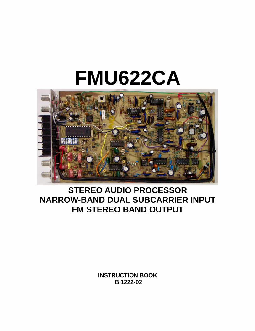
FMU622CA
STEREO AUDIO PROCESSOR
NARROW-BAND DUAL SUBCARRIER INPUT FM STEREO BAND OUTPUT
INSTRUCTION BOOK IB 1222-02

TABLE OF CONTENTS
SECTION 1.0 INTRODUCTION 2.0 INSTALLATION & OPERATING INSTRUCTIONS 3.0 SPECIFICATIONS 4.0 FUNCTIONAL DESCRIPTION 5.0 MAINTENANCE 6.0 TUNING PROCEDURES COMPONENET LOCATOR APPENDIX B
1.0 INTRODUCTION: GENERAL DESCRIPTION The FMU622CA is designed to receive and process into the FM stereo broadcast band any one of the stereo audio programs delivered by satellite as narrow-band frequency modulated sub carriers, normally above video, on selected transponders, such as fine arts radio WFMT on Satcom 3, transponder 3, along with TV Super station WGN in Chicago. This system incorporates complimentary dynamic range expansion to optimize the signal to noise ratio by a sliding frequency cut-off (variable de-emphasis process).
The RF output frequency of these units, like other FM SYSTEMS, INC. products, is adjustable in the field without changing crystals. This state of the art design uses a master crystal oscillator and a programmable phase-lock-loop (PLL) system to precisely set the output to any standard frequency in the FM Broadcast Band. Other frequencies outside the 88-108 MHz Band are available upon special request. The program output is also available as Base-band Audio, with separate balanced outputs for left and right channels. 2.0 INSTALLATION AND OPERATING INSTRUCTIONS: NOTE: This section assumes that the FMU622CA is tuned to the desired sub-carrier frequency and FM channel output frequency. If not, proceed to section 6.5, Tuning Procedures. Remove the unit from its shipping container and inspect for shipping damage. The FMU622CA is usually shipped already mounted in a PMS610 panel (1-¾” high x 19” standard rack width). The FMU622CA is mounted in a PMS610 mainframe power supply, if you have purchased a separate FMU622CA module to be installed in an existing PMS610, refer to Appendix B of this instruction set for the installation procedure. When power is applied, observe that the red “OFF FREQ” LED illuminates and flickers off, indicating that the RF output is locked on frequency.
Connect an RG59U cable between the “COMPOSITE” output of the satellite receiver and the “SUBCARRIER INPUT-IN” on the rear of the FMU622CA. Terminate the “SUBCARIER INPUT-OUT” with 75 ohms, either a resistor, or looped through into another unit with 75 ohms resistive termination.
FMU622CAisb page 1 of 19

Rotate the sub carrier “SQ” (Squelch) control (at the front panel on the left side) fully clockwise with a small flat-blade screwdriver. When the satellite receiver is tuned to a channel that contains sub-carriers at the frequencies the FMU622CA is set for, the green “SUBCARRIER-ON” LED on the front panel will come on. This indicates that the sub carriers are being received. In order to block noise on carrier loss, rotate the “SQ” control counter clockwise until the sub carrier “ON” LED is fully illuminated. Connect an RG59U cable between “FM CHAN OUTPUT-OUT” and the cable head-end combiner input. Terminate the “FM CHAN OUTPUT-IN” with 75 Ohms, or loop-thru from another unit with 75 Ohms resistive termination. Adjust the RF output level on the front panel right side to co-ordinate with the RF Band levels standard for your cable system. NOTE: Reversal of the RF channel output “IN” & “OUT” connections will result in a 20dB reduction of the output, due to the directional coupler. To connect he separate base-band audio left and right output, connect the low impedance output to any load of 600 Ohms (resistive) or higher, preferably balanced, although unbalanced loads will perform satisfactorily. The output level is 0 dBm at average program level, +10 dBm at 100% modulation. 3.0 SPECIFICAITONS: SUBCARRIER INPUT (DUAL): SPECIFICATION Frequency Range 4.5-8.5 MHz Fixed (specify) Deviation +/- 50 KHz or +/- 25 KHz (specify) Impedance Loop Through on 75 Ohm Line Level 20-300 mV pp Squelch Adjustable (front panel) Carrier Indicator Green LED (front panel) AUDIO OUTPUT : Processing Sliding De-Emphasis Frequency Response 40Hz - 15 KHz +/-1 dB Harmonic Distortion Less than 1% (0.2 % Typical) Audio Output Level 0 dBm APL (Balanced) FMU622CAisb page 2 of 19

FM STEREO BAND OUTPUT: Frequency (Agile) 88.1-107.9 MHz (100 KHz Steps) Frequency Stability +/-10 PPM (+/- 100 Hz) Maximum RF Level +25 to +50 dBmV (Adjustable) RF Impedance 75 Ohm Thru (Directional Coupler) Modulation (L+R) +/- 75 KHz Modulation (L-R) 38 KHz DBSC Pre-Emphasis 75 uS MECHANICAL Power -24 VDC @ 200 mA SIZE & MOUNTING: Requires 1/3 FM Systems, PMS610 mainframe power supply, which fits into a standard 19” wide rack with 17 13/16” between mounting rails, 1 ¾” high, 10 ¼” deep. The other 2 spaces in the PMS610 will accommodate additional FM Systems 600 series modules. The compact power supply in the PMS610 does not require a separate module location, as it is beside the three module locations. 4.0 FUNCTIONAL DESCRIPTION: INPUT: Where the subsections are dual, the description will be of the left channel only, except where the right channel differs, Adjustment of the controls is covered in Section 6 Tuning Procedures. INPUT Q1: The sub carrier input band pass filter consists of C101-107 and L101-104, which may be tuned to any sub-carrier frequency. Transistor Q1 couples the output of the filter to the relatively low input impedance of the limiter in U1. LIMITER AND DEMODULATOR, U1: U1, with associated external components, is a complete signal limiter and demodulator, with automatic fine tuning and adjustable squelch with indicator LED. FMU622CAisb page 3 of 19
LPF, U3: U3, with C126-128, L108 and R125-127, is a 15 KHz low pass filter with low output impedance to drive the following section. SLIDING DE-EMPHASIS, U4, U5, U6, AND Q5: U4 is a precision rectifier, used to control the output drive impedance of U5 into C141 such that the variable de-emphasis curve tracks the signal level appropriately. Adjustments for through level and de-emphasis provide precise tracking to accommodate production component tolerances. W5 provides a low impedance drive for negative feedback to stabilize the gain and operating point of U5 at low frequencies. U6 provides 10 dB of gain and buffers the high output impedance of U5 and C141 to feed the following stages. AUDIO OUTPUT, ½ U7 & U8: One half of U8 provides the 75 microsecond de-emphasis for the base-band audio output, and is used to set the drive level to U8, a semi-floating fully balanced audio output stage. U8 provides approximately 10dB of voltage gain, and is capable of driving loads of 600 Ohms or more, either balanced or unbalanced. When running unbalanced loads, the unused output terminal must e grounded, just as with a floating transformer coupled output. STEREO PILOT & CARRIER, U9 & U10: The stereo pilot and carrier frequencies (19 and 38 KHz) are digitally synthesized with U10, which is driven by U9, and crystal-controlled oscillator with multiple frequency dividers. This provides stable frequency, amplitude, and phase relationships. The synthesized sine-wave output are filtered to very low distortion by C473-C475, R476, & VR471 (19 KHz) and C483-C486, R485, & VR472. STEREO MATRIX & MODULATOR, ½ U7 and U12: The second half of U7 is driven by U6 in a matrix to produce L+R and L-R channels. The L+R channel is applied to the FM oscillator, via level control VR401. The L-R channel is applied, via level control VR402, to one input of the stereo multiplex modulator U12. The other input is driven by the 38 KHz carrier generator, U10. The output of U12 is a conventional double sideband, suppressed carrier amplitude modulated signal centered on 38 KHz. This signal is added to the L+R signal at the input to the FM oscillator, along with the 19 KHz pilot signal, also from U10. FMU622CAisb page 4 of 19
FREQUENCY MODULATED OSCILLATOR, Q6 Q7 & Q8:
Q6, Q7, and Q8, with associated components, comprise a voltage controlled FM oscillator operating in the 88-108 MHz FM stereo band. The frequency deviation is set by VR501, the master modulation control, which varies the drive to D501, a voltage controlled capacitor. This, with L501, controls the resonant frequency of oscillator Q6. Q7 buffers the output of Q6 and drives Q8, the RF output transistor. The RF output level is adjusted by VR503, accessible through a front panel hole with a small screwdriver. The output of Q8 is tuned to peak the desired frequency and reduce harmonics by C515-517 and L502-504. L504 is also the output directional coupling, in conjunction with R529. PHASE-LOCK-LOOP, Q9, Q10, U13, & U14: The FM oscillator center frequency is set by comparing its output with a precision frequency derived from a crystal oscillator. Q9 taps a portion of the FM oscillator output from Q7 and applies it to U13 a frequency divide by ten circuit, then to U14, which divides by the number programmed on frequency set switch SW501. The total division is down to 10 KHz, which is also the frequency generated by the reference crystal oscillator after it is separately divided. The two 10 KHz signals are applied to a phase comparator in U14. The output of the phase comparator is a control voltage proportional to any phase and frequency difference between the reference and the FM oscillator center frequency. Whenever the FM oscillator free-running frequency is outside the control range, the red unlock LED on the front panel lights, indicating that the RF output frequency is not controlled by the reference crystal. (See Section 6, Tuning Procedures, FM Channel Frequency Change, to correct this condition, which normally occurs only when switching to a new RF output frequency. VOLTAGE REGULATORS, U15, Q2, Q12, & Q16: U15 is a three terminal voltage regulator, set to -18 VDC. All power used In the FMU622CA passes through U15, essentially eliminating any fluctuations due to variations of the -24 VDC supply. Most of the unit operates directly from -18 VDC, although U1 & U11 operate from -12 VDC, regulated by a zener diode D101 and buffered by Q2 & Q12, and U13 & U14 operate from -5 VDC, regulated by emitter-follower Q16. FMU622CAisb page 5 of 19

5.0 MAINTENANCE: No routine maintenance is required. However, you may wish to check the audio output amplitude periodically to verify that the FMU622CA output is normal. It is recommended that the FMU622CA not be re-adjusted in the field. All other adjustments require specialized test equipment. In order to avoid degrading the overall performance, do not adjust any control in the FMU622CA “By ear”. In the event of a malfunction of the unit, please contact the factory. We will generally recommend that the unit be sent to the factory for repair and recalibration. However, if repair in the field must be accomplished, basic re-adjustment procedures follow in Section 6. 6.0 TUNING PROCEDURES: SUBCARRIER TUNING There is no requirement it “touch-up” the tuning of the sub carrier input circuitry and the factory strongly suggest that no adjustments be made except when there is a need to tune new sub carrier input channel frequencies. In this case, we recommend that the unit be returned to the factory for retuning. If circumstances require that the retuning be done in the field, the following procedure may be used: TEST EQUIPMENT REQUIRED: A. Deviation Meter. B. FM Generator. C. Oscilloscope. D. Distortion Analyzer. E. Audio Sine-wave Generator. TUNING OF THE BANDPASS FILTER: Connect the FM generator, set the approximately 1 V pp at the required sub carrier frequency to J2 (sub carrier input). Connect the scope probe to J1 (sub carrier out) and terminate with 75 Ohms. Adjust C101 (left channel, C201 for right channel) for best null at center frequency. Adjust the FM to +/- 300 KHz deviation at 50 Hz. FMU622CAisb page 6 of 19

Calibrate the scope to 50 KHz per horizontal division (deviation and horizontal deflection derived from audio generator). Adjust the horizontal position so that the desired sub carrier center frequency aligns with the center line of the oscilloscope. Connect the scope probe to C109 at the junction to R105 (C209 & R205 if right instead of left channel). Adjust C104 and C105 (left, C204 & C205 if right channel) for maximum amplitude and peak flatness throughout the range encompassed by the desired center frequency +/-65 KHz. 130 KHz “flat” pass band.
THIS COMPLETES THE BANDPASS FILTER ALIGNMENT. TUNING OF THE DISCRIMINATOR: The discriminator is automatically fine tuned to the sub carrier frequency. However, if the sub carrier frequency has been changed more than 1 MHz, it may be advantageous to optimize the THD (Total Harmonic Distortion) by adjusting C115 & C215. Connect the audio generator, set to 1000Hz, to the external input of the FM generator. Connect the RF output of the FM generator, set the desired sub carrier frequency, to the RF input of the modulation meter. Connect the demodulated audio output of the modulation meter to the audio input of the distortion analyzer. Connect the output of the distortion analyzer to the vertical input of the oscilloscope. Connect the auxiliary output of the signal generator to the external trigger input of the oscilloscope. Adjust the 1000Hz level to cause a sub-carrier deviation of +/- 50 KHz as measured on the 100 KHz scale with a 3 KHz band pass selected. Measure the THD of the audio oscillator FM generator combination. It should be less than 0.5%, if not, do not attempt to reduce the FMU622CA demodulator distortion, as the adjustment may add distortion in an attempt to cancel that of the test equipment. If the THD of the test equipment measures better than 0.5%, connect the RF output of the FM generator, set to 30mV, to the sub carrier input of the FMU622CA. Terminate the sub-carrier output with 75 Ohms. Connect the input to the distortion analyzer to the wiper of VR131 (Left), (VR231), if right channel. The audio level should measure within 3 dB of 0 dBm (1.5 to 3 V pp. Adjust C115 for minimum THD, it should be better than 0.7% FMU622CAisb page 7 of 19
TUNING THE DE-EMPHASIS: The de-emphasis tracking adjustments must be done on both channels if either is adjusted, to assure that the two are identical. These adjustments can be satisfactorily accomplished only with sufficient instrumentation, please attempt them only if you must. The FMU622CA utilizes a sliding de-emphasis circuit which complements that at the modulator. At 100% modulation the circuit frequency response is essentially flat. The circuit responds to program level by increasing the de-emphasis as the program level drops. There are two tracking adjustments in each channel of the FMU622CA, the first is to set the low frequency through level to a standard, the second is to set the high frequency through level to the same level at 100% modulation. The standard through levels must be identical on each channel for optimum stereo separation and frequency response, these levels will change if the sub-carrier frequency is changed, necessitating retuning the de-emphasis as follows. Modulate the sub-carrier 100% (+/-50 KHz) with 50 Hz. Measure signal level at U6 (7). Adjust VR131 for + 10 dBm output. Switch the modulating frequency to 15 KHz, verify that sub carrier deviation remains +/- 50 KHz. Adjust VR133 for +10 dBm output from U6. Verify that the circuit is functional by switching the modulating frequency to 2 KHz at 10% sub carrier deviation (+/-5 KHz). The output of U6 should drop to -21 dBm (a 31 dB drop from 100% modulation). AUDIO OUTPUT LEVEL AND BALANCE: There are two output adjustments. The first is to balance the tip and ring (T&R) levels, the second is to set the output level to a standard, generally +10 dBm into a balanced 600 Ohm load at 100% modulation. A convenient way to balance the T&R levels is to connect two precision 1% 300 Ohm resistors in series to make a center tapped 600 Ohm lead. Modulate the sub-carrier 100% with 1 KHz. Monitor the signal level at the junction of the two load resistors and adjust VR156 for the vest null. Check levels at T&R, then should be identical. Connecting either T or R to ground should increase the level of the opposite terminal by 6 dB +/- 1 dB. Connecting the center tap of the load to ground should have no effect on the level. FMU622CAisb page 8 of 19

STEREO MULTIPLEX ALIGNMENT: The stereo multiplex circuitry is best aligned with two matched FM sub-carrier generators, one for the left channel and another for the right. However, it is possible to accomplish the alignment with just one, that procedure will be described here, as most service people have only one FM generator available. Remove U7. Connect the scope probe to the junction of R463 and U12. Adjust VR451 for best 38 KHz carrier null. Continue as above, but also remove U10 and connect a lead from the audio generator, set the 1000 Hz, +10 dBm, to the positive lead of C402 at the L-R level adjustment, VR402. Adjust VR452 for best null. Check that the Master Modulation control, VR501, is near mid-position. Adjust VR472 for a pilot deviation of +/-7.5 KHz as measured on the modulation meter connected to the FM band output. Re-install U10, adjust VR402 (L-R) for a total deviation of +/-75 KHz. Connect the lead from the audio generator, still set to 1000Hz, +10 dBm, to the positive lead of C401 at the L+R level adjustment, VR401. Adjust VR401 for a total deviation of +/-75 KHz. Disconnect the signal generator and re-install U7. The stereo carrier (and pilot) frequencies are crystal controlled to better than +/-1 Hz accuracy. The crystal frequency may be trimmed over a narrow range by adjusting C472. As this is an extremely stable circuit, re-adjustment is unnecessary unless the crystal is replaced by one not tuned for a 30 pf load. In order to provide optimum stereo separation, the 19 KHz pilot phase zero crossings must coincide in time with the 38 KHz carrier zero crossings. Connect one probe of a dual trace scope to 19 KHz at the junction of C476 and VR472. Trigger the scope on this signal only. Adjust the vertical for precisely center scale with the input shorted and for full scale deflection with the signal AC coupled. Adjust the time base for one full cycle visible and the triggering to position the negative to positive zero crossing at center scale. Connect the second probe to 38 KHz at the junction of R486 and R459. Adjust the vertical for precisely center scale with the input shorted, and for approximately half scale deflection with the signal AC coupled. Adjust the19 KHz phase, VR471, relative to the 38 KHz phase, to align the negative to positive zero crossings. The horizontal scale may be expanded with the time base multiplier to facilitate accuracy. FMU622CAisb page 9 of 19
FM CHANNEL FREQUENCY CHANGE: The FMU622CA RF output is controlled by a phase lock loop (PLL) automatic frequency control system. As long as the average frequency of the FM carrier is equal to the reference frequency, the red “OFF FREQ” LED on the front panel will not light. To change the frequency, complete steps 6.5.2-6.5.4. Look up the binary equivalent of the desired operating frequency in Appendix A of this instruction book, set switch SW1, sections 1-10 (Located inside the top cover) in accordance with the binary code for the desired frequency. The “OFF FREQ” LED may illuminate, whether it does or not, continue through these steps. With a non-metallic flat blade screw driver tune L501, accessible inside the top cover, until the red “OFF FREQ” LED just extinguishes, then press the pushbutton switch next to L501 and continue to tune L501 until the red LED again extinguish the red LED, then release the button. This sets the PLL system to the center of its control range. Small changes of L501 tuning may cause the red LED to light momentarily, but is must be out when L501 is correctly set, when illuminated, the output frequency is not locked to the reference crystal frequency. Connect a field strength meter to the FM channel output “OUT” and terminate the “IN” connector with 75 Ohms. Tune C515 and C516 Multi-turn piston capacitors for maximum output. The output with RF output level control at maximum should be at least +50 dBmV. Note: Reversing connections to the FM channel “IN” and “OUT” on the rear panel will reduce readings about 20 dB due to the directional coupler being reversed. APPENDIX A: To change the RF output frequency of FM SYSTEMS 600 series modulators, two quick steps are essential:
1. Set the new frequency for the PLL (Phase Lock Loop) with the DIP switches on the circuit board, SW501. See the following tables for the switch positions.
2. Center the AFC (Automatic Frequency Control) range with the variable inductor
(coil) after setting the switches . If either of these steps is skipped, the frequency will be incorrect and/or will drift. FMU622CAisb page 10 of 19
SET FREQUENCY SWITCHES: Look up the settings for the Frequency Switches (SW501) in the accompanying table and carefully set each of the ten or fourteen switches. If the new frequency is outside the range of this table, it may be set as detailed in Section 4.0.0. CENTER AFC RANGE: After the switches are set to the new frequency, press pushbutton SW516 “AFC TEST” with a non-metallic tuning tool, adjust L501, “AFC CENTER” the variable inductor to center the oscillator range on the new output frequency. The OFF FREQ light will flicker off. Release the pushbutton, the OFF FREQ LED will remain off. The output frequency will be stable, phase-locked to the crystal reference oscillator. OUTPUT FILTER TUNING: If the frequency was changed considerably, retune the output filter by adjusting C516 & C515, the two variable capacitors nearest the output connectors, for peak output level. SWITCH SETTING FOR ANY FREQUENCY: NOTE: Although the frequency setting switches may be programmed over a very wide range, the oscillator will only work within the range of frequencies originally specified, attempts to operate far outside the specified range will be without success unless other components are changed. The sum of the open switch frequency increments is the output frequency. Refer to TABLE A-2 to determine the increments applicable. Begin with all switches = 0 (closed, rocker depressed). Starting with the most significant (largest) number, check to see if adding that frequency increment, (see Table A-2) to the total will exceed the desired frequency. If so, leave that switch closed. If not, open the switch and add its frequency to the total. FMU622CAisb page 11 of 19
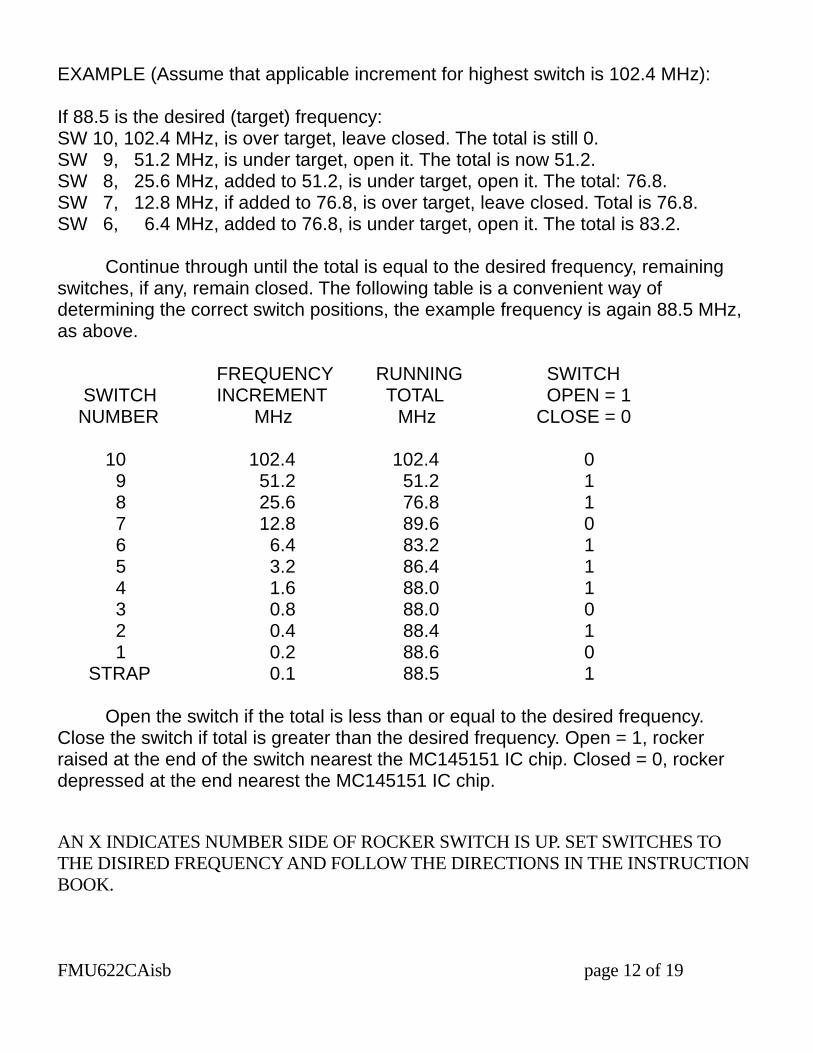
EXAMPLE (Assume that applicable increment for highest switch is 102.4 MHz): If 88.5 is the desired (target) frequency: SW 10, 102.4 MHz, is over target, leave closed. The total is still 0. SW 9, 51.2 MHz, is under target, open it. The total is now 51.2. SW 8, 25.6 MHz, added to 51.2, is under target, open it. The total: 76.8. SW 7, 12.8 MHz, if added to 76.8, is over target, leave closed. Total is 76.8. SW 6, 6.4 MHz, added to 76.8, is under target, open it. The total is 83.2. Continue through until the total is equal to the desired frequency, remaining switches, if any, remain closed. The following table is a convenient way of determining the correct switch positions, the example frequency is again 88.5 MHz, as above. FREQUENCY RUNNING SWITCH SWITCH INCREMENT TOTAL OPEN = 1 NUMBER MHz MHz CLOSE = 0 10 102.4 102.4 0 9 51.2 51.2 1 8 25.6 76.8 1 7 12.8 89.6 0 6 6.4 83.2 1 5 3.2 86.4 1 4 1.6 88.0 1 3 0.8 88.0 0 2 0.4 88.4 1 1 0.2 88.6 0 STRAP 0.1 88.5 1 Open the switch if the total is less than or equal to the desired frequency. Close the switch if total is greater than the desired frequency. Open = 1, rocker raised at the end of the switch nearest the MC145151 IC chip. Closed = 0, rocker depressed at the end nearest the MC145151 IC chip. AN X INDICATES NUMBER SIDE OF ROCKER SWITCH IS UP. SET SWITCHES TO THE DISIRED FREQUENCY AND FOLLOW THE DIRECTIONS IN THE INSTRUCTION BOOK. FMU622CAisb page 12 of 19
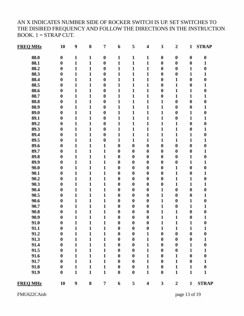
AN X INDICATES NUMBER SIDE OF ROCKER SWITCH IS UP. SET SWITCHES TO THE DISIRED FREQUENCY AND FOLLOW THE DIRECTIONS IN THE INSTRUCTION BOOK. 1 = STRAP CUT. FREQ MHz 10 9 8 7 6 5 4 3 2 1 STRAP 88.0 0 1 1 0 1 1 1 0 0 0 0 88.1 0 1 1 0 1 1 1 0 0 0 1 88.2 0 1 1 0 1 1 1 0 0 1 0 88.3 0 1 1 0 1 1 1 0 0 1 1 88.4 0 1 1 0 1 1 1 0 1 0 0 88.5 0 1 1 0 1 1 1 0 1 0 1 88.6 0 1 1 0 1 1 1 0 1 1 0 88.7 0 1 1 0 1 1 1 0 1 1 1 88.8 0 1 1 0 1 1 1 1 0 0 0 88.9 0 1 1 0 1 1 1 1 0 0 1 89.0 0 1 1 0 1 1 1 1 0 1 0 89.1 0 1 1 0 1 1 1 1 0 1 1 89.2 0 1 1 0 1 1 1 1 1 0 0 89.3 0 1 1 0 1 1 1 1 1 0 1 89.4 0 1 1 0 1 1 1 1 1 1 0 89.5 0 1 1 0 1 1 1 1 1 1 1 89.6 0 1 1 1 0 0 0 0 0 0 0 89.7 0 1 1 1 0 0 0 0 0 0 1 89.8 0 1 1 1 0 0 0 0 0 1 0 89.9 0 1 1 1 0 0 0 0 0 1 1 90.0 0 1 1 1 0 0 0 0 1 0 0 90.1 0 1 1 1 0 0 0 0 1 0 1 90.2 0 1 1 1 0 0 0 0 1 1 0 90.3 0 1 1 1 0 0 0 0 1 1 1 90.4 0 1 1 1 0 0 0 1 0 0 0 90.5 0 1 1 1 0 0 0 1 0 0 1 90.6 0 1 1 1 0 0 0 1 0 1 0 90.7 0 1 1 1 0 0 0 1 0 1 1 90.8 0 1 1 1 0 0 0 1 1 0 0 90.9 0 1 1 1 0 0 0 1 1 0 1 91.0 0 1 1 1 0 0 0 1 1 1 0 91.1 0 1 1 1 0 0 0 1 1 1 1 91.2 0 1 1 1 0 0 1 0 0 0 0 91.3 0 1 1 1 0 0 1 0 0 0 1 91.4 0 1 1 1 0 0 1 0 0 1 0 91.5 0 1 1 1 0 0 1 0 0 1 1 91.6 0 1 1 1 0 0 1 0 1 0 0 91.7 0 1 1 1 0 0 1 0 1 0 1 91.8 0 1 1 1 0 0 1 0 1 1 0 91.9 0 1 1 1 0 0 1 0 1 1 1 FREQ MHz 10 9 8 7 6 5 4 3 2 1 STRAP FMU622CAisb page 13 of 19

AN X INDICATES NUMBER SIDE OF ROCKER SWITCH IS UP. SET SWITCHES TO THE DISIRED FREQUENCY AND FOLLOW THE DIRECTIONS IN THE INSTRUCTION BOOK. 1 = STRAP CUT. FREQ MHz 10 9 8 7 6 5 4 3 2 1 STRAP 92.0 0 1 1 1 0 0 1 1 0 0 0 92.1 0 1 1 1 0 0 1 1 0 0 1 92.2 0 1 1 1 0 0 1 1 0 1 0 92.3 0 1 1 1 0 0 1 1 0 1 1 92.4 0 1 1 1 0 0 1 1 1 0 0 92.5 0 1 1 1 0 0 1 1 1 0 1 92.6 0 1 1 1 0 0 1 1 1 1 0 92.7 0 1 1 1 0 0 1 1 1 1 1 92.8 0 1 1 1 0 1 0 0 0 0 0 92.9 0 1 1 1 0 1 0 0 0 0 1 93.0 0 1 1 1 0 1 0 0 0 1 0 93.1 0 1 1 1 0 1 0 0 0 1 1 93.2 0 1 1 1 0 1 0 0 1 0 0 93.3 0 1 1 1 0 1 0 0 1 0 1 93.4 0 1 1 1 0 1 0 0 1 1 0 93.5 0 1 1 1 0 1 0 0 1 1 1 93.6 0 1 1 1 0 1 0 1 0 0 0 93.7 0 1 1 1 0 1 0 1 0 0 1 93.8 0 1 1 1 0 1 0 1 0 1 0 93.9 0 1 1 1 0 1 0 1 0 1 1 94.0 0 1 1 1 0 1 0 1 1 0 0 94.1 0 1 1 1 0 1 0 1 1 0 1 94.2 0 1 1 1 0 1 0 1 1 1 0 94.3 0 1 1 1 0 1 0 1 1 1 1 94.4 0 1 1 1 0 1 1 0 0 0 0 94.5 0 1 1 1 0 1 1 0 0 0 1 94.6 0 1 1 1 0 1 1 0 0 1 0 94.7 0 1 1 1 0 1 1 0 0 1 1 94.8 0 1 1 1 0 1 1 0 1 0 0 94.9 0 1 1 1 0 1 1 0 1 0 1 95.0 0 1 1 1 0 1 1 0 1 1 0 95.1 0 1 1 1 0 1 1 0 1 1 1 95.2 0 1 1 1 0 1 1 1 0 0 0 95.3 0 1 1 1 0 1 1 1 0 0 1 95.4 0 1 1 1 0 1 1 1 0 1 0 95.5 0 1 1 1 0 1 1 1 0 1 1 95.6 0 1 1 1 0 1 1 1 1 0 0 95.7 0 1 1 1 0 1 1 1 1 0 1 95.8 0 1 1 1 0 1 1 1 1 1 0 95.9 0 1 1 1 0 1 1 1 1 1 1 FREQ MHz 10 9 8 7 6 5 4 3 2 1 STRAP FMU622CAisb page 14 of 19
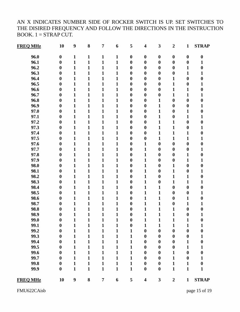
AN X INDICATES NUMBER SIDE OF ROCKER SWITCH IS UP. SET SWITCHES TO THE DISIRED FREQUENCY AND FOLLOW THE DIRECTIONS IN THE INSTRUCTION BOOK. 1 = STRAP CUT. FREQ MHz 10 9 8 7 6 5 4 3 2 1 STRAP 96.0 0 1 1 1 1 0 0 0 0 0 0 96.1 0 1 1 1 1 0 0 0 0 0 1 96.2 0 1 1 1 1 0 0 0 0 1 0 96.3 0 1 1 1 1 0 0 0 0 1 1 96.4 0 1 1 1 1 0 0 0 1 0 0 96.5 0 1 1 1 1 0 0 0 1 0 1 96.6 0 1 1 1 1 0 0 0 1 1 0 96.7 0 1 1 1 1 0 0 0 1 1 1 96.8 0 1 1 1 1 0 0 1 0 0 0 96.9 0 1 1 1 1 0 0 1 0 0 1 97.0 0 1 1 1 1 0 0 1 0 1 0 97.1 0 1 1 1 1 0 0 1 0 1 1 97.2 0 1 1 1 1 0 0 1 1 0 0 97.3 0 1 1 1 1 0 0 1 1 0 1 97.4 0 1 1 1 1 0 0 1 1 1 0 97.5 0 1 1 1 1 0 0 1 1 1 1 97.6 0 1 1 1 1 0 1 0 0 0 0 97.7 0 1 1 1 1 0 1 0 0 0 1 97.8 0 1 1 1 1 0 1 0 0 1 0 97.9 0 1 1 1 1 0 1 0 0 1 1 98.0 0 1 1 1 1 0 1 0 1 0 0 98.1 0 1 1 1 1 0 1 0 1 0 1 98.2 0 1 1 1 1 0 1 0 1 1 0 98.3 0 1 1 1 1 0 1 0 1 1 1 98.4 0 1 1 1 1 0 1 1 0 0 0 98.5 0 1 1 1 1 0 1 1 0 0 1 98.6 0 1 1 1 1 0 1 1 0 1 0 98.7 0 1 1 1 1 0 1 1 0 1 1 98.8 0 1 1 1 1 0 1 1 1 0 0 98.9 0 1 1 1 1 0 1 1 1 0 1 99.0 0 1 1 1 1 0 1 1 1 1 0 99.1 0 1 1 1 1 0 1 1 1 1 1 99.2 0 1 1 1 1 1 0 0 0 0 0 99.3 0 1 1 1 1 1 0 0 0 0 1 99.4 0 1 1 1 1 1 0 0 0 1 0 99.5 0 1 1 1 1 1 0 0 0 1 1 99.6 0 1 1 1 1 1 0 0 1 0 0 99.7 0 1 1 1 1 1 0 0 1 0 1 99.8 0 1 1 1 1 1 0 0 1 1 0 99.9 0 1 1 1 1 1 0 0 1 1 1 FREQ MHz 10 9 8 7 6 5 4 3 2 1 STRAP FMU622CAisb page 15 of 19
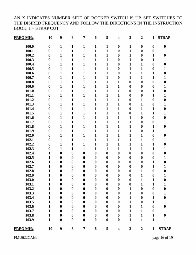
AN X INDICATES NUMBER SIDE OF ROCKER SWITCH IS UP. SET SWITCHES TO THE DISIRED FREQUENCY AND FOLLOW THE DIRECTIONS IN THE INSTRUCTION BOOK. 1 = STRAP CUT. FREQ MHz 10 9 8 7 6 5 4 3 2 1 STRAP 100.0 0 1 1 1 1 1 0 1 0 0 0 100.1 0 1 1 1 1 1 0 1 0 0 1 100.2 0 1 1 1 1 1 0 1 0 1 0 100.3 0 1 1 1 1 1 0 1 0 1 1 100.4 0 1 1 1 1 1 0 1 1 0 0 100.5 0 1 1 1 1 1 0 1 1 0 1 100.6 0 1 1 1 1 1 0 1 1 1 0 100.7 0 1 1 1 1 1 0 1 1 1 1 100.8 0 1 1 1 1 1 1 0 0 0 0 100.9 0 1 1 1 1 1 1 0 0 0 1 101.0 0 1 1 1 1 1 1 0 0 1 0 101.1 0 1 1 1 1 1 1 0 0 1 1 101.2 0 1 1 1 1 1 1 0 1 0 0 101.3 0 1 1 1 1 1 1 0 1 0 1 101.4 0 1 1 1 1 1 1 0 1 1 0 101.5 0 1 1 1 1 1 1 0 1 1 1 101.6 0 1 1 1 1 1 1 1 0 0 0 101.7 0 1 1 1 1 1 1 1 0 0 1 101.8 0 1 1 1 1 1 1 1 0 1 0 101.9 0 1 1 1 1 1 1 1 0 1 1 102.0 0 1 1 1 1 1 1 1 1 0 0 102.1 0 1 1 1 1 1 1 1 1 0 1 102.2 0 1 1 1 1 1 1 1 1 1 0 102.3 0 1 1 1 1 1 1 1 1 1 1 102.4 1 0 0 0 0 0 0 0 0 0 0 102.5 1 0 0 0 0 0 0 0 0 0 1 102.6 1 0 0 0 0 0 0 0 0 1 0 102.7 1 0 0 0 0 0 0 0 0 1 1 102.8 1 0 0 0 0 0 0 0 1 0 0 102.9 1 0 0 0 0 0 0 0 1 0 1 103.0 1 0 0 0 0 0 0 0 1 1 0 103.1 1 0 0 0 0 0 0 0 1 1 1 103.2 1 0 0 0 0 0 0 1 0 0 0 103.3 1 0 0 0 0 0 0 1 0 0 1 103.4 1 0 0 0 0 0 0 1 0 1 0 103.5 1 0 0 0 0 0 0 1 0 1 1 103.6 1 0 0 0 0 0 0 1 1 0 0 103.7 1 0 0 0 0 0 0 1 1 0 1 103.8 1 0 0 0 0 0 0 1 1 1 0 103.9 1 0 0 0 0 0 0 1 1 1 1 FREQ MHz 10 9 8 7 6 5 4 3 2 1 STRAP FMU622CAisb page 16 of 19
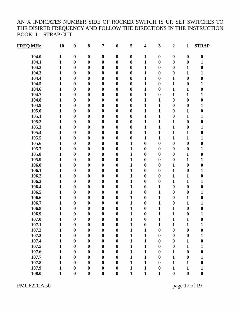
AN X INDICATES NUMBER SIDE OF ROCKER SWITCH IS UP. SET SWITCHES TO THE DISIRED FREQUENCY AND FOLLOW THE DIRECTIONS IN THE INSTRUCTION BOOK. 1 = STRAP CUT. FREQ MHz 10 9 8 7 6 5 4 3 2 1 STRAP 104.0 1 0 0 0 0 0 1 0 0 0 0 104.1 1 0 0 0 0 0 1 0 0 0 1 104.2 1 0 0 0 0 0 1 0 0 1 0 104.3 1 0 0 0 0 0 1 0 0 1 1 104.4 1 0 0 0 0 0 1 0 1 0 0 104.5 1 0 0 0 0 0 1 0 1 0 1 104.6 1 0 0 0 0 0 1 0 1 1 0 104.7 1 0 0 0 0 0 1 0 1 1 1 104.8 1 0 0 0 0 0 1 1 0 0 0 104.9 1 0 0 0 0 0 1 1 0 0 1 105.0 1 0 0 0 0 0 1 1 0 1 0 105.1 1 0 0 0 0 0 1 1 0 1 1 105.2 1 0 0 0 0 0 1 1 1 0 0 105.3 1 0 0 0 0 0 1 1 1 0 1 105.4 1 0 0 0 0 0 1 1 1 1 0 105.5 1 0 0 0 0 0 1 1 1 1 1 105.6 1 0 0 0 0 1 0 0 0 0 0 105.7 1 0 0 0 0 1 0 0 0 0 1 105.8 1 0 0 0 0 1 0 0 0 1 0 105.9 1 0 0 0 0 1 0 0 0 1 1 106.0 1 0 0 0 0 1 0 0 1 0 0 106.1 1 0 0 0 0 1 0 0 1 0 1 106.2 1 0 0 0 0 1 0 0 1 1 0 106.3 1 0 0 0 0 1 0 0 1 1 1 106.4 1 0 0 0 0 1 0 1 0 0 0 106.5 1 0 0 0 0 1 0 1 0 0 1 106.6 1 0 0 0 0 1 0 1 0 1 0 106.7 1 0 0 0 0 1 0 1 0 1 1 106.8 1 0 0 0 0 1 0 1 1 0 0 106.9 1 0 0 0 0 1 0 1 1 0 1 107.0 1 0 0 0 0 1 0 1 1 1 0 107.1 1 0 0 0 0 1 0 1 1 1 1 107.2 1 0 0 0 0 1 1 0 0 0 0 107.3 1 0 0 0 0 1 1 0 0 0 1 107.4 1 0 0 0 0 1 1 0 0 1 0 107.5 1 0 0 0 0 1 1 0 0 1 1 107.6 1 0 0 0 0 1 1 0 1 0 0 107.7 1 0 0 0 0 1 1 0 1 0 1 107.8 1 0 0 0 0 1 1 0 1 1 0 107.9 1 0 0 0 0 1 1 0 1 1 1 108.0 1 0 0 0 0 1 1 1 0 0 0 FMU622CAisb page 17 of 19
APPENDIX B PMS610 MAINFRAME AND POWER SUPPLY INSTRUCTIONS The PMS610 is a mainframe power supply for mounting FM SYSTEMS 600 series equipment. Up to three circuit board modules may be accommodated. These modules may be readily installed in the field with common hand tools, no soldering is required. MOUNTING AND SIZE: Fits Standard 19” wide rack. 1-¾” H x 10-¼” D. CAPACITY: Up to three FM SYSTEMS 600 series modules. POWER: 105-125 VAC 50/60 Hz 0.4 A input, 3 way Plug. CONNECTORS: Through hole access on the rear panel. WEIGHT: 4 lbs. minimum, 9 lbs. fully loaded. TO INSTALL AN ADDITIONAL MODULE: Select which of the three positions will be occupied by the new circuit board module. Remove the mainframe from the rack and disconnect the power. Remove the bottom cover, and the #4-40 x ¼” mounting studs adjacent to the new modules location from the mainframe. Remove the appropriate rear panel connector cover (blank) from the mainframe. Then remove the appropriate front panel “nameplate” blank from the mainframe. Install the new circuit board module with the components toward the top cover. Take care to avoid moving any of the pre-set controls (just a slight change can cause the unit to malfunction). Slip the connectors through the holes in the rear panel and drop the front edge of the circuit board onto the brackets attached to the front panel. Install two 3/8” lock washers and two 3/8-32 nuts on the outermost “F” connector barrels. Gently tighten the nuts while holding the circuit board against the front mounting brackets. Next install two #4-40 x ¼” studs (less lock washers) to secure the front of the board to the mounting brackets. Remove the top over from the mainframe. Connect the negative DC supply to the new circuit board from the PMS610 power distribution wire. 0.025” square connector pins are used, usually connected to a multiple jumper (provided) with mating female connectors which connect from one circuit board to the next. Power supply return is through the chassis. FMU622CAisb page 18 of 19
Push any LEDs (Light Emitting Diodes) straight into the appropriate mounting holes. (See instructions for the particular module being installed). Insert only until the dark collar around the colored LED is flush with the front panel, the collar must not protrude, in order to avoid interfering with the new nameplate. Mount the new front panel nameplate (Furnished with the circuit board module being installed). Temporarily set the new nameplate in place and check that all necessary cutouts are clear. Remove the paper peel coat from the adhesive baking of the nameplate, then slide the nameplate down around the LEDs onto the panel. Press gently to set the adhesive. Mount any additional panel components (switches, meters, potentiometer, etc.) with the hardware supplied. Gently tighten the fastener to secure the components, do not over tighten the hardware. Mount the new rear panel connector identification strips as illustrated in the instruction book for the particular module being installed. Connect input, output, and power cables. The green “POWER ON” indicator should be illuminated. Set any internal controls as required. CAUTION: Most circuit board modules have several adjustments which are carefully factory set with precision instruments for optimum performance. Change only those which must be adjusted, some control when misadjusted produce little change under normal operating conditions, but can seriously reduce the ability of the unit to function correctly under other conditions which may be encountered. Therefore, if you must adjust a control, place a mark on it before moving it, so that it may e returned to its original setting with reasonable accuracy. Disconnect power. Replace top and bottom covers and mount mainframe to rack. Reconnect power and check for normal operation of each module. FMU622CAisb page 19 of 19