fm spring grove timber sale fs haul roads
TRANSCRIPT


6026
6031
6378
104A
¬«127
¬«730
¬«126
¬«447
C19
C24
C22
C23
C21
Fox Swamp
Wadboo CreekGravel
HillSwamp
Browns
Branch
0.5 0 0.50.25 Miles
FM Spring Grove Timber SaleFS Haul Roads
Ü
LegendFS Haul RoadUS/State Highway
Other RoadSURFACE_TYPE, OPER_MAINT_LEVEL
Paved Road, Suitable for Passenger Cars
Gravel Road, Suitable for Passenger CarsDirt Road, Suitable for Passenger CarsPrimitive Road, Road not Maintained for Passenger CarsClosed RoadUnknown RoadStands
Surface Ownership (white FS, gray non-FS)FS_OWN_CODE
Francis Marion and Sumter National ForestPrivate/Other LandPrivate/Other Land (outside forest boundary)

ESTIMATE OF QUANTITIES Sheet 1 Of 10
ROAD NUMBER 104A 6031 6378 - -MILE POST (MILES) 0.85 0.1 0.75 - -
ITEM NO. DESCRIPTION
METHOD OF MEASURE UNIT
REVISION DATE QUANTITIES REMARKS
20110 Road Heavy Brushing CQ Miles 2006 0.85 0.75
20112 Road Mowing CQ Miles 2006 0.44
24901 Composite Ramp Construction, Slach Method C CQ LS 2006 1.00
30109 Aggregate Surface course,gradingFLBC,compaction method,A CQ Ton 2006 150.00 150.00 150.00
60201 18" Reinforced Concrete pipe, Class 111 CQ Foot 2006 54.00
60708 Cleaning culvert in place CQ Each 2006 1.00
62501 Seeding and Mulching,Dry method CQ Ac 2006 0.50
63311 Removing and install new gate sign system CQ LS 2006 1.00

2
FRANCIS MARION NATIONAL FOREST FM PONDBERRY TS
FSR 104A
SPRING GROVE A MP DESCRIPTION 0.00 BEGIN PROJECT AT INTERSECTION WITH S-447 0.00 – 0.85 SPOT SURFACE WITH 200 TONS OF AGGREGATE, GRADE FLBC, WHERE DIRECTED BY THE ENGINEER
• HEAVY BRUSHING
0.032 EXISTING GATE NEW GATE SIGNS REQUIRED. 0.414 EXISTING CULVERT CLEAN INLET AND OUTLET REPAIR INLET END 0.733 EXISTING CULVERT 0.85 END OF PROJECT AND TURNAROUND

3
FSR 6031
STATION DESCRIPTION
0+00 BEGIN PROJECT AT INTERSECTION WITH S 126 0+00 – 1+00 CONSTRUCT INTERSECTION A = 90DEG R = 30 DEG r L = 100’ W = 14’ 0+00 – 2+50 SPOT SURFACE WITH 150 TONS OF AGGREGATE, GRADE FLBC,
WHERE DIRECTED BY THE ENGINEER CONSTRUCT RAMP SEED AND MULCH ALL DISTURBED AREAS 0+05 INSTALL NEW 18” X 54’ RCP 1+00 BEGIN TRANSITION TURN AROUND 1+50 OBTAIN FULL 100’ WIDE TURN AROUND 2+50 END OF PROJECT AND TURNAROUND GENERAL NOTES:
1. SLASH DISPOSAL SHOULD BE SCATTERED 2. CONSTRUCT 12’ SINGLE LANE ROAD 3. USE 249 SPEC 4. MOTOR GRADE FINISH REQUIRED 5. SEE GATE DRAWING DETAILS FOR A ACCESSIBILITY REQUIREMENTS
4
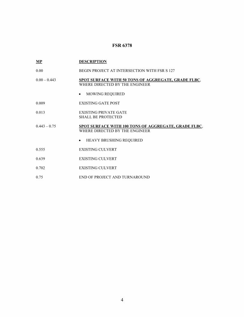
FSR 6378
MP DESCRIPTION 0.00 BEGIN PROJECT AT INTERSECTION WITH FSR S 127 0.00 – 0.443 SPOT SURFACE WITH 50 TONS OF AGGREGATE, GRADE FLBC,
WHERE DIRECTED BY THE ENGINEER • MOWING REQUIRED
0.009 EXISTING GATE POST 0.013 EXISTING PRIVATE GATE SHALL BE PROTECTED 0.443 – 0.75 SPOT SURFACE WITH 100 TONS OF AGGREGATE, GRADE FLBC,
WHERE DIRECTED BY THE ENGINEER • HEAVY BRUSHING REQUIRED
0.555 EXISTING CULVERT 0.639 EXISTING CULVERT 0.702 EXISTING CULVERT 0.75 END OF PROJECT AND TURNAROUND

Native Seeding Trails Developed by Jason Jennings and Robin Mackie 01/19/2012 All sites used for trials shall be dry, level or only slightly sloping (<10%), and sunny
1. MATERIALS AND APPLICATION RATES A. Fertilizer rate shall not exceed 400 lbs per acre 10-10-10 B. Lime to 1000 lbs per acre (May be less, desired soil pH is between 5.5 and 6) C. To prepare, apply fertilizer and lime, rake to form a crumbly seed bed, apply seed with a drill seeder,
hydroseeder, or broadcast spreader, then roll or cultipac to firm the seed bed and lightly cover seed with soil (1/4 inch to ½ inch soil optimal). Apply PAM-12 at a rate of 400 lbs/acre to increase soil/seed contact and to stabilize soil. Lightly mulch.
D. The following weed-free seed mixtures shall be used:
E. From Sept.1 to April 1 is the optimal window for seeding native species: 1). Nurse Crops
Wheat/Oats/Grain Rye 80 lb/acre Crimson Clover 10 lb /acre
2). Native Perennial Grasses – Seed source SC, NC, or GA Preferred; KY (Sumter only), Fl (FM only) Big Bluestem 2 lb/acre Indiangrass 3 lb/acre Little Bluestem 5 lb/acre 3). Native Forbs/Legumes – Seed source SC, NC, or GA Preferred, KY (Sumter only), Fl (FM only) Blackeyed Susan 1.0 lb/acre False Sunflower 1.0 lb/acre Lance Leaved Tickseed (Coreopsis) 1.0 lb /acre Partridge Pea 1.0 lb/acre Roundheaded Lespedeza 0.5 lb/acre Spiked Blazing Star 0.5 lb /acre If seeding from April 2 to August 31: 1). Nurse Crop Brown Top Millet 30 lb/acre 2). and 3). Native Perennial Grasses/Forbs/Legumes – Same as above
F. Apply weed-free hay, straw, or wood cellulose fiber mulch immediately after seeding at a rate of 1000 lbs/acre.
2. SOURCES OF NATIVE ECOTYPE SEED Roundstone Native Seed 1-888-531-2352 or 1-270-531-3032, roundstoneseed.com Ernst Conservation Seeds 1-800-873-3321 or 1-814-336-2404, ernstseed.com National Wild Turkey Federation, Conservation Seed Program, outdoordealhound.com/c-179-warm-season-grasses-forbs, Southeast Coastal Plains or Southeast Upland Mix, respectively, 1-800-THE-NWTF Mellow Marsh Farm 1-919-742-1200, mellowmashfarm.com

FM&S 201.1 PART 1 – SECTION C - DESCRIPTION/SPECIFICATIONS/WORK STATEMENT C.01 – DESCRIPTION – Heavy Brushing or Mowing
A. SCOPE OF CONTRACT- Contractor shall furnish all labor, equipment, materials, tools, transportation, supplies (including safety), supervision, and perform all work necessary for heavy brushing, and or mowing in accordance with these specifications and drawings. The work consists of mechanical and hand heavy brushing on road right-of-ways as designated in the plan and figure 102-1.
C.02 - GENERAL SPECIFICATIONS
A. ROAD STRUCTURE DEFINITIONS – Graphic definitions of road structural terms are shown in THE DRAWINGS.
C. PUBLIC SAFETY AND TRAFFIC CONTROL – The Contractor shall exercise caution and care while pursuing the work to prevent unnecessary conflict with, or potential hazard to road users.
The Contractor shall post warning signs with flags on each end of the section of road being worked. Signs shall be of the size, quantity and colors as required in the current edition of the “Manual of Uniform Traffic Control Devices”, (MUTCD). A copy of MUTCD is located in each District Rangers office and may be available to the Contractor for in-office reference on request. These signs shall be moved as needed to properly delineate and identify the section of road being maintained. At no time shall these signs be more than 2 miles from operating equipment and shall be in place only when equipment or personnel are actually performing operations. All slow-moving equipment shall have a reflectorized “slow moving” vehicle emblem properly attached.
All work shall be scheduled so that at the end of the workday, the road is passable for the type of traffic normally using the road. If, for any reason, traffic hazards are left adjacent to the road after normal work period, they shall be properly signed as hazards and visibly illuminated at night. Segments of unfinished work, which may present a hazard to road users, shall not be left in the roadway overnight, during weekends or holidays.

C.03 - TECHNICAL SPECIFICATIONS
A. HEAVY BRUSHING - Heavy brushing shall consist of machine and hand cutting of all brush and trees from road shoulder for a distance of 12 feet or to the original clearing limits (see 102-1) on both sides of the road. Either method shall include brushing of all plant growth around signs, culverts, and bridges within designated cutting areas. Brush and trees shall be cut to within 3 inches of ground level, mower height or mower height above standing water in ditches. Trees within clearing limits that exceed 5 inches in diameter at breast height are merchantable and shall be treated as such by the contractor if salvageable. Trees over 10 inches in diameter at breast height can be left on back slope of ditch if they do not present a sight or safety problem. Trees leaning into the roadway shall be cut at the base with disposal handled according to size. All merchantable trees within the clearing limits shall be removed according to the provisions of the timber sale contract. Overhanging branches or limbs shall be trimmed to give a clear height of 14 feet in traveled way and clearing limits. Work includes any additional brushing needed beyond 12 feet for safe sight distance at road intersections and blind curves, as determined by the Engineer. Contractor can dispose of all cut material by other means than removing cut material out of the clearing limits.
MOWING – Mowing shall consist of cutting grass and woody plat growth three inches diameter or less, four inches above ground as specified to the existing clearing limits. Maximum mowing height shall be four inches above ground or standing water. Routine operations shall consist of mowing all growth out from centerline to a point at least eight feet beyond shoulder on each side of the road with heavy duty rotary mower. Roads with ditches will require mowing the front slope and at least one four foot strip on the back slope of the ditch opposite the traveled way, to a maximum width of fourteen feet from shoulder. All mowing heavy equipment shall operate only within the travel way. Any additional mowing for safe sight distance at road intersections or blind curves is considered a part of this activity. This activity also includes brushing around road signs, culverts, culvert markers, barrier post, gates bridges, and other appurtenances. Brushing shall be to a point one foot beyond appurtenance and then tapered back to the normal mowing width. Contractor shall perform plumbing (vertical alignment) of all culvert marker post.
All heavy brush and trees shall be cut to fall away from the roadway as much as possible. Debris cut or thrown by machinery into road ditches shall be removed to outside of ditch and placed in such a way as not to fall or wash back into ditch.

All rock larger than 3 inches in diameter that are thrown onto the riding surface through the Contractor’s operations shall be removed. All woody material larger than 1 inch in diameter or 2 feet in length and any other debris, which could cause tire damage, shall be removed from the riding surface.
B. EQUIPMENT SPECIFICATIONS
1. General - All Equipment proposed to be used for performance of the work shall be of the size, type, in satisfactory operating condition and capable of producing at the manufacturer’s rated horsepower. Contractor shall furnish all fuel, oil, grease, repairs, and pay any other expenses incidental to operation of the equipment.
To reduce the chance of invasive plants being spread into the National Forest, any mechanical equipment shall be pressure washed prior to beginning work on the National Forest. It applies to any mechanical equipment that could harbor clumps of vegetative material; such as bush hogs. This pertains particularly to any equipment coming in from Florida, Louisiana, Mississippi, south Georgia, or Alabama.
Any movement or transportation of equipment to or from the work areas required to pursue the work, to repair or replace the equipment, or for Contractor’s convenience, shall be at the Contractor’s expense.
Any equipment removed from the forest shall require cleaning as stated above before being moved back onto the forest.
2. Tractor and Rotary Mower – Equipment furnished may be heavy-duty farm tractor or motor grader equipment with an operable articulated or telescopic boom mower. The vehicle shall have a minimum of 60 PTO horsepower and a minimum weight of 5000 pounds capable of cutting to clearing limits while being within the traveled way. The mower shall be a rotary type that has a minimum reach of 12 feet, and can efficiently cut grass, brush, and trees with diameters up to 3 inches.

3. Inspection of Equipment – The Contractor’s proposed equipment shall be made available to the Contracting Officer for inspection prior to award of the contract. If, at any time, during the course of the contract any equipment is deemed unsatisfactory, the Contracting Officer may order removal of the unsatisfactory equipment and may require that satisfactory replacement equipment be provided at Contractor’s expense.
All equipment shall be inspected on site by the COR or inspector prior to starting work to verify equipment has been properly cleaned to meet specifications.
4. Replacement Equipment – If a unit of equipment breaks down or otherwise becomes inoperative, and is not restored to operating condition within three (3) days, the Contractor will be notified in writing to correct the deficiencies or furnish replacement equipment meeting specifications within four (4) calendar day.
C.04 - INSPECTION AND ACCEPTANCE
Inspection of the work performed under this contract shall be made by the ER or the designated Inspector as the work progresses. Inspections shall be conducted at intervals necessary to ensure compliance with the contract specifications and provisions.
C.05 - MEASUREMENT AND PAYMENT
A. BASIS OF PAYMENT - The accepted quantities will be paid at the unit price shown in the Schedule of items.
Pay Item Description Pay Unit
201(10)
Road Heavy Brushing
MILES
201(11)
Road Heavy Brushing
LS
201(12)
Road Mowing
MILES
201(13)
Road Mowing
LS


LEAD-OFF DITCH
NOT TO SCALE
TYPICAL SECTION
CLOSE ROAD LEVEL 1
HORIZONTAL CLEARING & GRUBBING
20'
VERTICAL CLEARING LIMITS
14' HIGH
NOT TO SCALE


FS SUPPLEMENTS SPECIFICATION FP03
FM SPRING GROVE TS
Table of Contents
Table of Contents ............................................................................................................................ 1
Preface............................................................................................................................................. 3
101 - Terms, Format, and Definitions ............................................................................................. 3
101.01 Meaning of Terms ........................................................................................................... 3
101.01 Meaning of Terms ........................................................................................................... 3
101.03 Abbreviations. ................................................................................................................. 3
101.04 Definitions....................................................................................................................... 4
101.04 Definitions....................................................................................................................... 7
102 - Bid, Award, and Execution of Contract ................................................................................ 8
102 Bid, Award, and Execution of Contract ............................................................................... 8
103 - Scope of Work ....................................................................................................................... 8
Deletions ..................................................................................................................................... 8
104 - Control of Work..................................................................................................................... 8
Deletions ..................................................................................................................................... 8
104.06 Use of Roads by Contractor ............................................................................................ 8
105 - Control of Material ................................................................................................................ 9
105.02 Material Sources. ............................................................................................................ 9
105.02(a) Government-provided sources. ................................................................................... 9
105.05 Use of Material Found in the Work. ............................................................................... 9
106 - Acceptance of Work .............................................................................................................. 9
106.07 Delete .............................................................................................................................. 9
107 - Legal Relations and Responsibility to the Public ................................................................ 10
107.05 Responsibility for Damage Claims. .............................................................................. 10
107.06 Contractor’s Responsibility for Work. .......................................................................... 10
107.08 Sanitation, Health, and Safety ....................................................................................... 10

107.09 Legal Relationship of the Parties. ................................................................................. 10
107.10 Environmental Protection. ............................................................................................ 10
108 - Prosecution and Progress ..................................................................................................... 11
108 Delete. ................................................................................................................................ 11
109 - Measurement and Payment .................................................................................................. 12
109 Deletions ............................................................................................................................ 12
109.02 Measurement Terms and Definitions. ........................................................................... 12
151 - Mobilization......................................................................................................................... 13
155 - Schedules for Construction Contracts ................................................................................. 13
155 Delete. ................................................................................................................................ 13
204 - Excavation and Embankment .............................................................................................. 13
204.11 Compaction. .................................................................................................................. 26
249 - Composite Road Construction ............................................................................................. 27
301 - Untreated Aggregate Courses .............................................................................................. 31
301 Title Change. ...................................................................................................................... 32
301.05 Compacting ................................................................................................................... 32
602 - Culverts and Drains ............................................................................................................. 33
602.03 General. ......................................................................................................................... 33
625 - Turf Establishment .............................................................................................................. 33
625.05 Watering. ....................................................................................................................... 33
625.07 Seeding. (a) Dry method. .............................................................................................. 33
625.07 Seeding. (b) Hydraulic method. .................................................................................... 33
Table 625-1. Fertilizer Application Rate. ................................................................................. 33
633 - Permanent Traffic Control ................................................................................................... 34
633.03 General. ......................................................................................................................... 34
718 - Traffic Signing and Marking Material ................................................................................. 34
718.05 Aluminum Panels .......................................................................................................... 34

Preface Preface_wo_03_15_2004_m
Delete all but the first paragraph and add the following:
The Forest Service, US Department of Agriculture has adopted FP-03 for construction of National Forest System Roads.
101 - Terms, Format, and Definitions 101.00_nat_us_07_25_2005
101.01_nat_us_01_22_2009
101.01 Meaning of Terms Delete all references to the TAR (Transportation Acquisition Regulations) in the specifications.
101.01_nat_us_01_22_2009
101.01 Meaning of Terms Delete all references to the FAR (Federal Acquisition Regulations) in the specifications.
101.03_nat_us_06_16_2006
101.03 Abbreviations.
Add the following to (a) Acronyms:
AFPA MSHA NIST NESC WCLIB
American Forest and Paper Association Mine Safety and Health Administration National Institute of Standards and Technology National Electrical Safety Code West Coast Lumber Inspection Bureau
.
Add the following to (b) SI symbols:

mp Milepost
ppm Part Per Million
101.04_nat_us_03_29_2007
101.04 Definitions.
Delete the following definitions and substitute the following:
Bid Schedule--The Schedule of Items.
Bridge--No definition. Contractor--The individual or legal entity contracting with the Government for performance of prescribed work. In a timber sale contract, the contractor is the “purchaser”. Culvert--No definition. Right-of-Way--A general term denoting (1) the privilege to pass over land in some particular line (including easement, lease, permit, or license to occupy, use, or traverse public or private lands), or (2) Real property necessary for the project, including roadway, buffer areas, access, and drainage areas.
Add the following: Adjustment in Contract Price--“Equitable adjustment,” as used in the Federal Acquisition Regulations, or “construction cost adjustment,” as used in the Timber Sale Contract, as applicable. Change--“Change” means “change order” as used in the Federal Acquisition Regulations, or “design change” as used in the Timber Sale Contract. Design Quantity--“Design quantity” is a Forest Service method of measurement from the FS-96 Forest Service Specifications for the Construction of Roads and Bridges. Under these FP specifications this term is replaced by the term “Contract Quantities”. Forest Service--The United States of America, acting through the Forest Service, U.S. Department of Agriculture. Neat Line--A line defining the proposed or specified limits of an excavation or structure. Pioneer Road--Temporary construction access built along the route of the project. Purchaser--The individual, partnership, joint venture, or corporation contracting with the Government under the terms of a Timber Sale Contract and acting independently or through agents, employees, or subcontractors.

Protected Streamcourse--A drainage shown on the plans or timber sale area map that requires designated mitigation measures. Road Order--An order affecting and controlling traffic on roads under Forest Service jurisdiction. Road Orders are issued by a designated Forest Officer under the authorities of 36 CFR, part 260.
Schedule of Items--A schedule in the contract that contains a listing and description of construction items, quantities, units of measure, unit price, and amount.
Utilization Standards--The minimum size and percent soundness of trees described in the specifications to determine merchantable timber.
Add Figure 101-1—Illustration of road structure terms:

Figure 101-1—Illustration of road structure terms.
101.04_nat_us_11_06_2007

101.04 Definitions. Delete the following definitions:
Contract Modification
Day
Notice to Proceed
Solicitation

102 - Bid, Award, and Execution of Contract 102.00_nat_us_02_16_2005
102 Bid, Award, and Execution of Contract
Delete Section 102 in its entirety.
103 - Scope of Work 103.00_nat_us_02_16_2005
Deletions
Delete all but subsection 103.01 Intent of Contract.
104 - Control of Work 104.00_nat_us_06_16_2006
Deletions
Delete Sections 104.01, 104.02, and 104.04.
104.06_nat_us_02_17_2005
Add the following subsection:
104.06 Use of Roads by Contractor
The Contractor is authorized to use roads under the jurisdiction of the Forest Service for all activities necessary to complete this contract, subject to the limitations and authorizations designated in the Road Order(s) or described in the contract, when such use will not damage the roads or national forest resources, and when traffic can be accommodated safely.

105 - Control of Material 105.02_nat_us_01_18_2007
105.02 Material Sources.
105.02(a) Government-provided sources.
Add the following: Comply with the requirements of 30 CFR 56, subparts B and H. Use all suitable material for aggregate regardless of size unless otherwise designated. When required, re-establish vegetation in disturbed areas according to section 625.
105.05_nat_us_05_12_2004
105.05 Use of Material Found in the Work.
Delete 105.05 (a) and (b) and the last sentence of the second paragraph and substitute the following: Materials produced or processed from Government lands in excess of the quantities required for performance of this contract are the property of the Government. The Government is not obligated to make reimbursement for the cost of producing these materials.
106 - Acceptance of Work 106.07_nat_us_05_11_2004
106.07 Delete Delete subsection 106.07.

107 - Legal Relations and Responsibility to the Public 107.05_nat_us_05_11_2004
107.05 Responsibility for Damage Claims.
Delete the entire subsection.
107.06_nat_us_06_16_2006
107.06 Contractor’s Responsibility for Work. Delete the following from the first paragraph.
“except as provided in Subsection 106.07”.
107.08_nat_us_03_29_2005
107.08 Sanitation, Health, and Safety
Delete the entire subsection.
107.09_nat_us_06_16_2006
107.09 Legal Relationship of the Parties.
Delete the entire subsection.
107.10_nat_us_06_16_2006
107.10 Environmental Protection.
Add the following: Design and locate equipment repair shops, stationary refueling sites, or other facilities to minimize the potential and impacts of hazardous material spills on Government land. Before beginning any work, submit a Hazardous Spill Plan. List actions to be taken in the event of a spill. Incorporate preventive measures to be taken, such as the location of mobile refueling facilities, storage and handling of hazardous materials, and similar information. Immediately notify the CO of all hazardous material spills. Provide a written narrative report form no later than 24 hours after the initial report and include the following:
• Description of the item spilled (including identity, quantity, manifest number, and other identifying information).
• Whether amount spilled is EPA or state reportable, and if so whether it was reported, and to whom.

• Exact time and location of spill including a description of the area involved.
• Containment procedures.
• Summary of any communications the Contractor had with news media, Federal, state and local regulatory agencies and officials, or Forest Service officials.
• Description of clean-up procedures employed or to be employed at the site including final disposition and disposal location of spill residue.
When available provide copies of all spill related clean up and closure documentation and correspondence from regulatory agencies. The Contractor is solely responsible for all spills or leaks that occur during the performance of this contract. Clean up spills or leaks to the satisfaction of the CO and in a manner that complies with Federal, state, and local laws and regulations.
108 - Prosecution and Progress 108.00_nat_us_02_16_2005
108 Delete.
Delete Section 108 in its entirety.

109 - Measurement and Payment 109.00_nat_us_02_17_2005
109 Deletions
Delete the following entire subsections:
109.06 Pricing of Adjustments.
109.07 Eliminated Work.
109.08 Progress Payments.
109.09 Final Payment.
109.02_nat_us_06_16_2006
109.02 Measurement Terms and Definitions.
(b) Contract quantity. Add the following: Contract quantities will be adjusted only when there are errors in the original design of 15% or more. Change the following: “(b) Cubic yard” to “(c) Cubic yard”. Add the following definition: (p) Thousand Board Feet (Mbf). 1,000 board feet based on nominal widths, thickness, and extreme usable length of each piece of lumber or timber actually incorporated in the job. For glued laminated timber, 1,000 board feet based on actual width, thickness, and length of each piece actually incorporated in the job.

151 - Mobilization 151.03_nat_us_08_05_2005
151.03 Payment
Delete the entire subsection and add the following:
151.03 Payment
Mobilization is considered an indirect cost of this contract and will not be compensated as a separate work item.
155 - Schedules for Construction Contracts 155.00_nat_us_05_11_2004
155 Delete.
Delete Section 155 in its entirety.
204 - Excavation and Embankment 204.00_nat_us_03_26_2009
Replace Section 204 in its entirety with the following:
Description
204.01 This work consists of excavating material and constructing embankments. This includes furnishing, hauling, stockpiling, placing, disposing, sloping, shaping, compacting, and finishing earthen and rocky material. 204.02 Definitions.
(a) Excavation. Excavation consists of the following:
(1) Roadway excavation. All material excavated from within the right-of-way or easement areas, except subexcavation covered in (2) below and structure excavation covered in Sections 208 and 209. Roadway excavation includes all material encountered regardless of its nature or characteristics.

(2) Subexcavation. Material excavated from below subgrade elevation in cut sections or from below the original groundline in embankment sections. Subexcavation does not include the work required by Subsections 204.05, 204.06(b), and 204.06(c). (3) Borrow excavation. Material used for embankment construction that is obtained from outside the roadway prism. Borrow excavation includes unclassified borrow, select borrow, and select topping.
(b) Embankment construction. Embankment construction consists of placing and compacting roadway or borrow excavation. This work includes:
(1) Preparing foundation for embankment; (2) Constructing roadway embankments; (3) Benching for side-hill embankments; (4) Constructing dikes, ramps, mounds, and berms; and (5) Backfilling subexcavated areas, holes, pits, and other depressions.
(c) Conserved topsoil. Excavated material conserved from the roadway excavation and embankment foundation areas that is suitable for growth of grass, cover crops, or native vegetation. (d) Waste. Excess and unsuitable roadway excavation and subexcavation that cannot be used.

Material
204.03 Conform to the following Subsections: Backfill material 704.03 Select borrow 704.07 Select topping 704.08 Topping 704.05 Unclassified borrow 704.06 Water 725.01
Construction Requirements
204.04 Preparation for Roadway Excavation and Embankment Construction. Clear the area of vegetation and obstructions according to Sections 201 and 203. 204.05 Reserved. 204.06 Roadway Excavation. Excavate as follows:
(a) General. Do not disturb material and vegetation outside the construction limits. Incorporate only suitable material into embankments. Replace any shortage of suitable material caused by premature disposal of roadway excavation. Dispose of unsuitable or excess excavation material according to Subsection 204.14. At the end of each day's operations, shape to drain and compact the work area to a uniform cross-section. Eliminate all ruts and low spots that could hold water. Retrieve material deposited outside of the clearing limits as directed by the CO. Place unsuitable material in designated areas. (b) Rock cuts. Blast rock according to Section 205. Excavate rock cuts to 6 inches below subgrade within the roadbed limits. Backfill to subgrade with topping or with other suitable material. Compact the material according to Subsection 204.11 (c) Earth cuts. Scarify earth cuts to 6 inches below subgrade within the roadbed limits. Compact the scarified material according to Subsection 204.11. (d) Pioneer Roads. Road pioneering, slash disposal, and grubbing of stumps may proceed concurrently with excavation. Conduct excavation and placement operations so material to be treated under Section 201 will not be incorporated into the roadway unless specified in the slash treatment method. Maintain drainage during pioneering operations. Remove snow and ice in advance of the work and deposit beyond the roadway limits in a manner that will not waste material or generate sediment. Do not incorporate snow and ice into embankments. Place snow or ice in a manner to prevent resource damage.

204.07 Subexcavation. Excavate material to the limits designated by the CO. Take cross-sections according to Section 152. Prevent unsuitable material from becoming mixed with the backfill. Dispose of unsuitable material according to Subsection 204.14. Backfill the subexcavation with topping, or other suitable material. Compact the material according to Subsection 204.11. 204.08 Borrow Excavation. Use all suitable roadway excavation in embankment construction. Do not use borrow excavation when it results in excess roadway excavation. Deduct excess borrow excavation from the appropriate borrow excavation quantity. Obtain borrow source acceptance according to Subsection 105.02. Develop and restore borrow sources according to Subsection 105.03. Do not excavate beyond the established limits. When applicable, shape the borrow source to permit accurate measurements when excavation is complete. 204.09 Preparing Foundation for Embankment Construction. Prepare foundation for embankment construction as follows:
(a) Embankment less than 4 feet high over natural ground. When designated, remove topsoil and break up the ground surface to a minimum depth of 6 inches by plowing or scarifying. Compact the ground surface according to Subsection 204.11. (b) Embankments over an existing asphalt, concrete, or gravel road surface. Scarify gravel roads to a minimum depth of 6 inches. Scarify or pulverize asphalt and concrete roads to 6 inches below the pavement. Reduce all particles to a maximum size of 6 inches and produce a uniform material. Compact the surface according to Subsection 204.11. (c) Embankment across ground not capable of supporting equipment. Dump successive loads of embankment material in a uniformly distributed layer to construct the lower portion of the embankment. Limit the layer thickness to the minimum depth necessary to support the equipment. (d) Embankment on an existing slope steeper than 1V:3H. Cut horizontal benches in the existing slope to a sufficient width to accommodate placement and compaction operations and equipment. Bench the slope as the embankment is placed and compacted in layers. Begin each bench at the intersection of the original ground and the vertical cut of the previous bench.
204.10 Embankment Construction. Incorporate only suitable roadway excavation material into the embankment. When the supply of suitable roadway excavation is exhausted, furnish unclassified borrow to complete the embankment. Obtain written approval before beginning construction of embankments over 6 feet high at subgrade centerline. Construct embankments as follows:
(a) General. At the end of each day's operations, shape to drain and compact the embankment surface to a uniform cross-section. Eliminate all ruts and low spots that could hold water.

During all stages of construction, route and distribute hauling and leveling equipment over the width and length of each layer of material. Compact embankment side slopes flatter than 1V:1.75H with a tamping type roller or by walking with a dozer. For slopes 1V:1.75H or steeper, compact the slopes as construction of the embankment progresses. Where placing embankment on one side of abutments, wing walls, piers, or culvert headwalls, compact the material using methods that prevent excessive pressure against the structure. Where placing embankment material on both sides of a concrete wall or box structure, conduct operations so compacted embankment material is at the same elevation on both sides of the structure. Where structural pilings are placed in embankment locations, limit the maximum particle size to 4 inches. (b) Embankment within the roadway prism. Place embankment material in horizontal layers not exceeding 12 inches in compacted thickness. Incorporate oversize boulders or rock fragments into the 12-inch layers by reducing them in size or placing them individually as required by (c) below. Compact each layer according to Subsection 204.11 before placing the next layer. Material composed predominately of boulders or rock fragments too large for 12-inch layers may be placed in layers up to 24 inches thick. Incorporate oversize boulders or rock fragments into the 24-inch layer by reducing them in size or placing them individually according to (c) below. Place sufficient earth and smaller rocks to fill the voids. Compact each layer according to Subsection 204.11 before placing the next layer. (c) Individual rock fragments and boulders. Place individual rock fragments and boulders greater than 24 inches in diameter as follows:
(1) Reduce rock to less than 48 inches in the largest dimension. (2) Distribute rock within the embankment to prevent nesting. (3) Place layers of embankment material around each rock to a depth not greater than that permitted by (b) above. Fill all the voids between rocks. (4) Compact each layer according to Subsection 204.11 before placing the next layer.
(d) Embankment outside of roadway prism. Where placing embankment outside the staked roadway prism, place material in horizontal layers not exceeding 24 inches in compacted thickness. Compact each layer according to Subsection 204.11.
204.11 Compaction. Compact the embankment using one of the following methods as specified:
(a) Compaction A. Use AASHTO T 27 to determine the amount of material retained on a Number 4 sieve. If there is more than 80 percent retained on the No. 4 sieve use procedure (1).

If there is 50 to 80 percent retained on the No. 4 sieve use procedure (2). If there is less than 50 percent retained on the No. 4 sieve use procedure (3).
(1) Adjust the moisture content to a level suitable for compaction. Fill the interstices around rock with earth or other fine material as practical. Use compression-type rollers at speeds less than 6feet per second and vibratory rollers at speeds less than 3 feet per second. Compact each layer of material full width with one of the following and until there is no visible evidence of further consolidation.
(a) Four roller passes of a vibratory roller having a minimum dynamic force of 40,000 pounds impact per vibration and a minimum frequency of 1000 vibrations per minute. (b) Eight roller passes of a 20-ton compression-type roller. (c) Eight roller passes of a vibratory roller having a minimum dynamic force of 30,000 pounds impact per vibration and a minimum frequency of 1000 vibrations per minute.
Increase the compactive effort for layers deeper than 12 inches as follows:
• For each additional 6 inches or fraction thereof, increase the number of roller passes in (a) above by four passes. • For each additional 6 inches or fraction thereof, increase the number of roller passes in (b) and (c) above, by eight passes.
(2) Use AASHTO T 99 to determine the optimum moisture content of the portion of the material passing a No. 4 sieve. Multiply this number by the percentage of material passing a No. 4 sieve, and add 2 percent to determine the optimum moisture content of the material. Adjust the moisture content of material classified A-1 through A-5 to a moisture content suitable for compaction. Adjust the moisture content of material classified A-6 and A-7 to within 2 percent of the optimum moisture content. Use compression-type rollers at speeds less than 6 feet per second and vibratory rollers at speeds less than 3 feet per second. Compact each layer of material full width according to (1) above.
(3) Classify the material according to AASHTO M 145. For material classified A-1 or A-2-4, determine the maximum density according to AASHTO T 180, method D. For other material classifications, determine the optimum moisture content and maximum density according to AASHTO T 99, method C. Adjust the moisture content of material classified A-1 through A-5 to a moisture content suitable for compaction. Adjust the moisture content of material classified A-6 and A-7 to within 2 percent of the optimum moisture content. Use compression-type or vibratory rollers. Compact each layer of material full width to at least 95 percent of the maximum density. Determine the in-place density and moisture content according to AASHTO T 310 or other approved test procedures. When required, use AASHTO T 224 to correct for coarse particles.

(b) Compaction B. Place material by end dumping to the minimum depth needed for operation of spreading equipment. Adjust the moisture content of the material to obtain a mass that will not visibly deflect under the load of the hauling and spreading equipment. Operate compaction equipment over the full width of each layer until there is no visible evidence of further consolidation or, if when a sheepsfoot roller is used, the roller “walks out” of the layer. Make at least three complete passes. (c) Compaction C. Place material by end dumping to the minimum depth needed for operation of spreading equipment. Level and smooth each embankment layer before placing the next layers. Operate hauling and spreading equipment uniformly over the full width of each layer. Construct a solid embankment with adequate compaction by working smaller rock and fines in with the larger rocks to fill the voids, and by operating hauling and spreading equipment uniformly over the full width of each layer as the embankment is constructed.
204.12 Ditches. Slope, grade, and shape ditches. Remove all projecting roots, stumps, rock, or similar matter. Maintain all ditches in an open condition and free from leaves, sticks, and other debris. Form furrow ditches by plowing or using other acceptable methods to produce a continuous furrow. Place all excavated material on the downhill side so the bottom of the ditch is approximately 18 inches below the crest of the loose material. Clean the ditch using a hand shovel, ditcher, or other suitable method. Shape to provide drainage without overflow. 204.13 Sloping, Shaping, and Finishing. Complete slopes, ditches, culverts, riprap, and other underground minor structures before placing aggregate courses. Slope, shape, and finish as follows:
(a) Sloping. Leave all earth slopes with uniform roughened surfaces, except as described in (b) below, with no noticeable break as viewed from the road. Except in solid rock, round tops and bottoms of all slopes including the slopes of drainage ditches. Round material overlaying solid rock to the extent practical. Scale all rock slopes. Slope rounding is not required on tolerance class D though M roads. If a slide or slipout occurs on a cut or embankment slope, remove or replace the material, and repair or restore all damage to the work. Bench or key the slope to stabilize the slide. Reshape the cut or embankment slope to an acceptable condition. (b) Stepped slopes. Where required by the contract, construct steps on slopes of 1⅓V:1H to 1V:2H. Construct the steps approximately 18 inches high. Blend the steps into natural ground at the end of the cut. If the slope contains nonrippable rock outcrops, blend steps into the rock. Remove loose material found in transitional area. Except for removing large rocks that may fall, scaling stepped slopes is not required. (c) Shaping. Shape the subgrade to a smooth surface and to the cross-section required. Shape slopes to gradually transition into slope adjustments without noticeable breaks. At the ends of

cuts and at intersections of cuts and embankments, adjust slopes in the horizontal and vertical planes to blend into each other or into the natural ground. (d) Finishing. Finish the roadbed to be smooth and uniform, and shaped to conform to the typical sections. Remove unsuitable material from the roadbed and replace it with suitable material. Finish roadbeds to the tolerance class shown in table 204-2.Ensure that the subgrade is visibly moist during shaping and dressing. Scarify to 6 inches below the bottom of low sections, holes, cracks, or depressions and bring back to grade with suitable material. Maintain proper ditch drainage. For surfaced roads, remove all material larger than 6 inches from the top 6 inches of the roadbed. For unsurfaced roads, use one of the following methods to finish the roadbed:
(1) Method A. Remove all material larger than 6 inches from the top 6 inches of the roadbed and replace with suitable material. (2) Method B. Use a vibratory grid roller or approved equal with a minimum weight of 10 tons. Roll at least 5 full-width passes or until there is no visible evidence of further consolidation. (3) Method C. For roads designated as Construction Tolerance Class K, L, or M, finish the roadbed by spreading the excavation. Eliminate rock berms.
204.14 Disposal of Unsuitable or Excess Material. Dispose of unsuitable or excess material at designated sites or legally off of the project. When there is a pay item for waste, shape and compact the waste material in its final location. Do not mix clearing or other material not subject to payment with the waste material. 204.15 Acceptance. See Table 204-1 for sampling and testing requirements. Material for embankment and conserved topsoil will be evaluated under Subsections 106.02 and 106.04. Excavation and embankment construction will be evaluated under Subsections 106.02 and 106.04. Clearing and removal of obstructions will be evaluated under Sections 201 and 203.
Measurement
204.16 Measure the Section 204 items listed in the bid schedule according to Subsection 109.02 and the following as applicable.
(a) Roadway excavation. Measure roadway excavation in its original position as follows:
(1) Include the following volumes in roadway excavation:

(a) Roadway prism excavation; (b) Rock material excavated and removed from below subgrade in cut sections; (c) Unsuitable material below subgrade and unsuitable material beneath embankment areas when a pay item for subexcavation is not shown in the bid schedule; (d) Ditches, except furrow ditches measured under a separate bid item; (eTopsoil; (f) Borrow material used in the work when a pay item for borrow is not shown in the bid schedule; (g) Loose scattered rocks removed and placed as required within the roadway; (h) Conserved material taken from stockpiles and used in Section 204 work; and (i) Slide and slipout material not attributable to the Contractor's method of operation.
(2) Do not include the following in roadway excavation: (a) Overburden and other spoil material from borrow sources; (b) Overbreakage from the backslope in rock excavation; (c) Water or other liquid material; (d) Material used for purposes other than required; (e) Roadbed material scarified in place and not removed; (f) Material excavated when stepping cut slopes; (g) Material excavated when rounding cut slopes; (h) Preparing foundations for embankment construction; (i) Material excavated when benching for embankments; (j) Slide or slipout material attributable to the Contractor's method of operation; (k) Conserved material taken from stockpiles constructed at the option of the Contractor; and (l) Material excavated outside the established slope limits.
(3) When both roadway excavation and embankment construction pay items are shown in the bid schedule, measure the following as roadway excavation only:
(a) Unsuitable material below subgrade in cuts and unsuitable material beneath embankment areas when a pay item for subexcavation is not shown in the bid schedule; (b) Slide and slipout material not attributable to the Contractor’s method of operations; and (c) Drainage ditches, channel changes, and diversion ditches.
(b) Unclassified borrow, select borrow, and select topping. When measuring by the cubic yard measure in its original position. If borrow excavation is measured by the cubic yard in place, take initial cross-sections of the ground surface after stripping overburden. Upon completion of excavation and after the borrow source waste material is returned to the source, retake cross-sections before replacing the overburden. Do not measure borrow excavation used in place of excess roadway excavation. (c) Embankment construction. Measure embankment construction in its final position. Do not make deductions from the embankment construction quantity for the volume of minor structures.

(1) Include the following volumes in embankment construction:
(a) Roadway embankments; (b) Material used to backfill subexcavated areas, holes, pits, and other depressions; (c) Material used to restore obliterated roadbeds to original contours; and (d) Material used for dikes, ramps, mounds, and berms.
(2) Do not include the following in embankment construction: (a) Preparing foundations for embankment construction; (b) Adjustments for subsidence or settlement of the embankment or of the foundation on which the embankment is placed; and (c) Material used to round fill slopes.
(d) Rounding cut slopes. Measure rounding cut slopes horizontally along the centerline of the roadway if a pay item for slope rounding is included in the bid schedule. If a pay item for slope rounding is not included in the bid schedule slope rounding will be considered subsidiary to excavation. (e) Waste. Measure waste by the cubic yard in its final position. Take initial cross-sections of the ground surface after stripping over burden. Upon completion of the waste placement, retake cross-sections before replacing overburden. (f) Slope scaling. Measure slope scaling by the cubic yard in the hauling vehicle.
Payment
204.17 The accepted quantities will be paid at the contract price per unit of measurement for the Section 204 pay items listed in the bid schedule. Payment will be full compensation for the work prescribed in this Section. See Subsection 109.05.

Tab
le 2
04-1
Sa
mpl
ing
and
Test
ing
Req
uire
men
ts
Rep
ortin
g T
ime
Bef
ore
usin
g in
wor
k
“
Bef
ore
plac
ing
next
la
yer
Bef
ore
usin
g in
wor
k
“ “ “
Bef
ore
plac
ing
next
la
yer
(1)
Min
imum
of 5
poi
nts p
er p
roct
or
Split
Sa
mpl
e
Yes
, whe
n re
ques
ted
“ —
Yes
, whe
n re
ques
ted
“ “ “ —
Poin
t of
Sam
plin
g
Proc
esse
d m
ater
ial
befo
re
inco
rpor
atin
g in
wor
k
“
In-p
lace
Proc
esse
d m
ater
ial
befo
re
inco
rpor
atin
g i
k
“ “ “
In-p
lace
Sam
plin
g
Freq
uenc
y
1 pe
r soi
l typ
e
1 pe
r soi
l typ
e bu
t no
t les
s tha
n 1
per
1300
0 d3
1 pe
r 600
0 yd
2 bu
t no
t les
s tha
n 1
per
laye
r
1 pe
r soi
l typ
e bu
t no
t les
s tha
n 1
for
each
day
of
prod
uctio
n
“ “
1 pe
r soi
l typ
e bu
t no
t les
s tha
n 1
per
3
1 pe
r 600
0 yd
2 bu
t no
t les
s tha
n 1
per
laye
r
Tes
t Met
hods
Sp
ecifi
catio
ns
AA
SHTO
M 1
45
AA
SHTO
T 1
80,
met
hod
D(1
) or T
99,
m
etho
d C
(1)
AA
SHTO
T 3
10 o
r ot
her a
ppro
ved
proc
edur
es
AA
SHTO
M 1
45
AA
SHTO
T 2
7
& T
11
AA
SHTO
T 8
9
AA
SHTO
T 1
80,
met
hod
D(1
) or T
99,
m
etho
d C
(1)
AA
SHTO
T 3
10 o
r ot
her a
ppro
ved
proc
edur
es
Cat
egor
y
—
—
—
—
—
—
—
—
Cha
ract
eris
tic
Cla
ssifi
catio
n
Moi
sture
-de
nsity
Com
pact
ion
Cla
ssifi
catio
n
Gra
datio
n
Liqu
id li
mit
Moi
sture
-de
nsity
Com
pact
ion
Typ
e of
Acc
epta
nce
(Sub
sect
ion)
Mea
sure
d an
d te
sted
for c
onfo
rman
ce
(106
.04)
Mea
sure
d an
d te
sted
for c
onfo
rman
ce
(106
.04)
Mat
eria
l or
Prod
uct
Topp
ing
(704
.05)
&
uncl
assi
fied
bo
rrow
(704
.06)
Sele
ct b
orro
w
(704
.07
& S
elec
t to
ppin
g (7
04.0
8)

Tab
le 2
04-1
(con
tinue
d)
Sam
plin
g an
d Te
stin
g R
equi
rem
ents
Rep
ortin
g T
ime
Bef
ore
usin
g
in w
ork
“
Bef
ore
plac
ing
next
laye
r
Bef
ore
plac
ing
next
laye
r
(1)
Min
imum
of 5
poi
nts p
er p
roct
or.
Split
Sa
mpl
e
Yes
, whe
n re
ques
ted
“ —
—
Poin
t of
Sam
plin
g
Sour
ce o
f M
ater
ial
“
In-p
lace
In-p
lace
Sam
plin
g
Freq
uenc
y
1 pe
r soi
l typ
e
1 pe
r soi
l typ
e bu
t not
le
ss th
an 1
per
13
,000
yd3
1 pe
r 350
0 yd
2 but
not
le
ss th
an 1
per
laye
r
1 pe
r 250
0 yd
2
Tes
t Met
hods
Sp
ecifi
catio
ns
AA
SHTO
M 1
45
AA
SHTO
T 1
80,
met
hod
D(1
) or T
99,
m
etho
d C
(1)
AA
SHTO
T 3
10 o
r ot
her a
ppro
ved
proc
edur
es
AA
SHTO
T 3
10 o
r ot
her a
ppro
ved
proc
edur
es
Cat
egor
y
—
—
—
—
Cha
ract
eris
tic
Cla
ssifi
catio
n
Moi
sture
- de
nsity
Com
pact
ion
Com
pact
ion
Typ
e of
Acc
epta
nce
(Sub
sect
ion)
Mea
sure
d an
d te
sted
fo
r con
form
ance
(1
06.0
4)
Mea
sure
d an
d te
sted
fo
r con
form
ance
(1
06.0
4)
Mat
eria
l or
Prod
uct
Earth
em
bank
men
t (2
04.1
1,
Com
pact
ion
A)
Top
of su
bgra
de
(204
.11
Com
pact
ion
A)

Tab
le 2
04-2
C
onst
ruct
ion
Tol
eran
ces
Tol
eran
ce C
lass
(a)
M
+2.0
(c)
(c)
+20
(a) M
axim
um a
llow
able
dev
iatio
n fro
m c
onstr
uctio
n sta
kes a
nd d
raw
ings
. (b
) Max
imum
allo
wab
le d
evia
tion
from
stak
ed sl
ope m
easu
red
from
slop
e sta
kes o
r hin
ge p
oint
s. (c
) Unl
ess
othe
rwise
sho
wn
the
cent
erlin
e al
ignm
ent a
nd su
bgra
de e
leva
tion,
as
built
, hav
e no
hor
izon
tal c
urve
s w
ith a
radi
us o
f les
s tha
n 80
feet
, and
no
verti
cal c
urve
s w
ith a
cur
ve
leng
th o
f les
s th
an 8
0 fe
et w
hen
the
alge
brai
c di
ffere
nce
in th
e gr
ade
chan
ge is
less
than
10
perc
ent,
or a
cur
ve le
ngth
of l
ess
than
100
feet
whe
n th
e al
gebr
aic
diffe
renc
e of
the
grad
e ch
ange
is g
reat
er th
an o
r equ
al to
10
perc
ent.
The c
ente
rline
gra
de is
not
to ex
ceed
20
perc
ent i
n 10
0 fe
et o
f len
gth.
L
+2.0
+3.0
+5.0
+20
K
+2.0
+2.0
+3.0
+20
J +2.0
+3.0
+3.0
+10
I
+2.0
+2.0
+2.0
+10
H
+1.0
+1.5
+1.5
+10
G
+1.5
+1.0
+1.5
+10
F +1.0
+1.0
+1.0
+5
E
+1.0
+0.5
+1.0
+5
D
+1.0
+0.5
+0.5
+5
C
+1.0
+0.2
+0.5
+5
B
+0.5
+0.2
+0.2
+5
A
+0.5
+0.1
+0.2
+3
Roa
dbed
wid
th
(ft)
Subg
rade
el
evat
ion
(ft)
Cen
terli
ne
alig
nmen
t (ft)
Slop
es,
exca
vatio
n, a
nd
emba
nkm
ent
(% sl
ope(b
) )
204.11_nat_us_04_11_2005

204.11 Compaction.
Delete the first paragraph and replace it with the following: For compaction according to method (a), (b), or (c), use AASHTO T 27 to determine the amount of material retained on a Number. 4 sieve. For compaction methods (d) or (e) no sieve test is required. Add the following compaction methods: (d) Layer Placement Method (Hauling and Spreading Equipment). Place material by end dumping to the minimum depth needed for operation of spreading equipment. Level and smooth each embankment layer before placing the next layers. Operate hauling and spreading equipment uniformly over the full width of each layer. Construct a solid embankment with adequate compaction by working smaller rock and fines in with the larger rocks to fill the voids, and by operating hauling and spreading equipment uniformly over the full width of each layer as the embankment is constructed.
(e) Layer Placement (Roller Compaction) Method. Place material by end dumping to the minimum depth needed for operation of spreading equipment. Adjust the moisture content of the material to obtain a mass that will not visibly deflect under the load of the hauling and spreading equipment. Operate compaction equipment over the full width of each layer until visible deformation of the layer ceases or, in when a sheepsfoot roller is used, the roller “walks out” of the layer. Make at least three complete passes.

249 - Composite Road Construction 249.00_0116_us_03_31_2005
Description
249.01 This work consists of clearing and grubbing, excavation and embankment, and removal of all construction slash including designated trees. During excavation and embankment, excavate and use borrow material; excavate drainage; shape the roadway, including approaches, turnarounds, ditches, and drainage dips; and place all excavated material, regardless of nature. Perform erosion control by furnishing and placing seed, fertilizer, mulch, and tackifer. Construct the roadway in conformance with the dimensions shown on the plans or designated by the CO.
Materials
249.02 Ensure that materials meet the requirements specified in the following section and subsection:
Seeding and Mulching 625
Stabilizing Emulsion Tackifers 713.02
Construction Requirements 249.03Clearing and Disposal. Protect construction stakes and construction control markers. Remove or treat all trees, snags, downed timber, brush, and stumps within the clearing limits according to the following specifications:
(a) Merchantable Timber. Treat according to Subsection 201.06
(b) Unmerchantable Timber. Treat according to Subsection 203.05 Method (i)

(c) Large Construction Slash. Treat construction slash larger than 3 inches in diameter and longer than 3 feet by one or more of the following methods, as shown on the plans:
(1) Method A. Incorporate construction slash in the embankment.
(2) Method B. Windrow construction slash inside the clearing limits. When slash is windrowed, place it approximately parallel to the roadway outside the toe of the fill slope.
(3) Method C. Scatter construction slash outside the roadway without damaging trees. Limb all logs. Place logs and stumps away from trees, positioned so they will remain in place and are not on top of one another.
(4) Method D. Construct piles that are free of soil, with smaller slash well mixed with larger slash. Buck unmerchantable logs into lengths less than 18 feet prior to placement in piles.
(5) Method E. Sidecast construction slash into the area below the roadway. Slash my be sidecast beyond the lower clearing limit not to exceed 10 feet.
(6) Method F. Bury construction slash within the roadway limits. Construct mats in layers and cover the mats with at least 18 inches of rock and soil.
(7) Method G. Construct piles of construction slash in the areas designated on the ground. Construct the piles so that burning does not damage standing trees. Burn the piles until all the material remaining in the pile is charred or ash.
(8) Method H. Bury the construction slash outside the roadway the locations designated on the ground. Construct mats in layers, and cover the mats with at least 18 inches of rock and soil. Slope the final surface to drain.
(9) Method J. Construct a debris mat of construction slash under the road subgrade. Use tree limbs, tops cull logs, split stumps, wood chunks, and other debris to form a mat. Place stumps upside down and blended into the mat.
Small Construction Slash. Construction slash less than 3 inches in diameter and less than 3 feet long may be incorporated into embankments so long as the material is distributed so that it does not result in concentrations or matting.
Immediately remove slash deposited in stream courses.

Fell all dead trees outside the clearing limits that lean toward the road and are sufficiently tall to reach the roadbed. Fell hazard or unstable live trees designated on the ground outside the clearing limits before felling timber in the immediate clearing vicinity.
Leave stump heights less than 1 foot or one-third of the stump diameter whichever is greater, measured on the side adjacent to the highest ground. Leave felled trees outside the clearing limits in place.
249.04 Pioneering. Do not undercut the final back slope during pioneer operations. Deposit material inside the roadway limits. Do not restrict drainage.
249.05 Grubbing. Grub within the specified limits. Stumps outside the grubbing limits remain if cut no higher than 1 foot or one-third of the stump diameter, whichever is greater, above the original ground, measured on the uphill side, unless otherwise designated. Grub stumps that will protrude through the subgrade or have less than 6 inches of cover.
249.06 Excavation and Embankment. Construct the roadway to conform to the typical sections shown on the plans. Protect backslopes from being undercut. Embankment may be placed by side casting and end dumping.
Locate and use borrow material, and remove and treat unsuitable or excess material, as designated.
Place rocks that are too large to be incorporated in the embankment outside the traveled way on the downhill side such that they will not roll, obstruct drainage, or hinder roadbed use and maintenance.
Leave slopes that are to be seeded in a roughened condition.

Shape and finish the roadbed to the condition ordinarily accomplished by a crawler tractor with dozer blade to provide drainage of surface water. Do not permit individual rocks to protrude more than 4 inches above the subgrade of the roadbed. A motor grader finish is not required.
Observe a width tolerance of (+) 18 inches f or the traveled way.
249.07 Erosion Control. Perform erosion control measures, including seeding. Use methods and applications rates, and types of seed, fertilizer, mulch, and tackifer, as specified in Section 625. Apply materials uniformly to the areas to be treated..
Measurement
249.08 Measure the Section 249 items listed in the bid schedule according to Subsection 109.02.
Payment
249.09 The accepted quantities will be paid at the contract price per unit of measurement for the Section 249 pay items listed in the bid schedule. Payment will be full compensation for the work prescribed in this Section. See Subsection 109.05.
301 - Untreated Aggregate Courses 301.00_nat_us_03_03_2005
301 Title Change.
Change the title to: Section 301 Aggregate Courses
301.05_nat_us_05_17_2005
301.05 Compacting
Delete and replace with the following:

Compact each layer full width. Roll from the sides to the center, parallel to the centerline of the road. Along curbs, headers, walls, and all places not accessible to the roller, compact the material with approved tampers or compactors. Compact the aggregate using one of the following methods as specified:
Compaction A. Operating spreading and hauling equipment over the full width of the travelway. Compaction B. Operate rollers and compact as specified in Subsection 204.11(a)(1). Compaction C. Moisten or dry the aggregate to a uniform moisture content between 5 and 7 percent based on total dry weight of the mixture. Operate rollers and compact as specified in Subsection 204.11(a)(1). Compaction D. Compact to a density of at least 95 percent of the maximum density, as determined by AASHTO T 99, method C or D. Compaction E. Compact to a density of at least 96 percent of the maximum density, as determined by the Modified Marshall Hammer Compaction Method (available upon request from USDA Forest Service, Regional Materials Engineering Center, P.O. Box 7669, Missoula, MT 59807). Compaction F. Compact to a density of at least 95 per-cent of the maximum density, as determined by AASHTO T 180, method C or D. Compaction G. Compact to a density of at least 100 percent of the maximum density as determined by the Modified Marshall Hammer Compaction Method (available upon request from USDA Forest Service, Regional Materials Engineering Center, P.O. Box 7669, Missoula, MT 59807).
For all compaction methods, blade the surface of each layer during the compaction operations to remove irregularities and produce a smooth, even surface. When a density requirement is specified, determine the in place density and moisture content according to AASHTO T 310 or other approved test procedures.
301 - Untreated Aggregate Courses 301.00_nat_us_03_03_2005

301 Title Change.
Change the title to: Section 301 Aggregate Courses
301.05_nat_us_05_17_2005
301.05 Compacting
Delete and replace with the following: Compact each layer full width. Roll from the sides to the center, parallel to the centerline of the road. Along curbs, headers, walls, and all places not accessible to the roller, compact the material with approved tampers or compactors. Compact the aggregate using one of the following methods as specified:
Compaction A. Operating spreading and hauling equipment over the full width of the travelway. Compaction B. Operate rollers and compact as specified in Subsection 204.11(a)(1). Compaction C. Moisten or dry the aggregate to a uniform moisture content between 5 and 7 percent based on total dry weight of the mixture. Operate rollers and compact as specified in Subsection 204.11(a)(1). Compaction D. Compact to a density of at least 95 percent of the maximum density, as determined by AASHTO T 99, method C or D. Compaction E. Compact to a density of at least 96 percent of the maximum density, as determined by the Modified Marshall Hammer Compaction Method (available upon request from USDA Forest Service, Regional Materials Engineering Center, P.O. Box 7669, Missoula, MT 59807). Compaction F. Compact to a density of at least 95 per-cent of the maximum density, as determined by AASHTO T 180, method C or D. Compaction G. Compact to a density of at least 100 percent of the maximum density as determined by the Modified Marshall Hammer Compaction Method (available upon request from USDA Forest Service, Regional Materials Engineering Center, P.O. Box 7669, Missoula, MT 59807).
For all compaction methods, blade the surface of each layer during the compaction operations to remove irregularities and produce a smooth, even surface. When a density requirement is specified, determine the in place density and moisture content according to AASHTO T 310 or other approved test procedures.
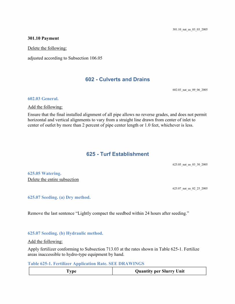
301.10_nat_us_03_03_2005
301.10 Payment
Delete the following:
adjusted according to Subsection 106.05
602 - Culverts and Drains 602.03_nat_us_09_06_2005
602.03 General.
Add the following: Ensure that the final installed alignment of all pipe allows no reverse grades, and does not permit horizontal and vertical alignments to vary from a straight line drawn from center of inlet to center of outlet by more than 2 percent of pipe center length or 1.0 feet, whichever is less.
625 - Turf Establishment 625.05_nat_us_03_30_2005
625.05 Watering. Delete the entire subsection
625.07_nat_us_02_25_2005
625.07 Seeding. (a) Dry method.
Remove the last sentence “Lightly compact the seedbed within 24 hours after seeding.”
625.07 Seeding. (b) Hydraulic method.
Add the following: Apply fertilizer conforming to Subsection 713.03 at the rates shown in Table 625-1. Fertilize areas inaccessible to hydro-type equipment by hand.
Table 625-1. Fertilizer Application Rate. SEE DRAWINGS Type Quantity per Slurry Unit

: : __lbs
: : __lbs
Apply the seed mixture at the rate of __________ kilograms of live seed per __________ (hectare/slurry unit). Include a tracer material consisting of either wood fiber mulch or grass cellulose fiber mulch to provide visible evidence of uniform application. Add the tracer to the slurry at a rate of __________ (400 pound per acre or 100 pound per slurry unit). Seed areas inaccessible to hydro-type equipment by hand.
633 - Permanent Traffic Control 633.03_nat_us_03_03_2005
633.03 General.
Delete the subsection and add the following: Furnish traffic control devices and guide signs according to the MUTCD, approved USDA-FS and state supplements, the current edition of USDA-FS EM-7100-15 Sign and Poster Guidelines for the Forest Service, and Standard Highway Signs published by FHWA. Submit the sign list for approval before ordering.
718 - Traffic Signing and Marking Material 718.05_nat_us_08_05_2009
718.05 Aluminum Panels Delete the third paragraph and replace with the following:
Clean, degrease and properly prepare the panels according to methods recommended by the sheeting manufacturer. Conversion coatings will conform to ASTM B-921 or ASTM B-449.